

Page 1

SERVICE MANUAL
SERVICE MANUAL
DV-SP406
Ref. No. 4063
062008
DVD PLAYER
MODEL DV-SP406
Europe & Others only
Black and Silver models
BTDD, STDD
BTPP, STPP
BTUA, STUA
120V AC, 60Hz
220-240V AC, 50/60Hz
110-240V AC, 50/60Hz
ON/STANDBY
OPEN/CLOSE
CLEAR
MUTING
TOP MENU
ENTER
SETUP
AUDIO SUBTITLE ANGLE DISPLAY
ZOOM
RESOLUTION
PROGRAM
MARKER
SEARCH
REPEAT
RC-725DV
RC-725DV
RECEIVER
ON/STANDBY
INPUT
VOL
MENU
RETURN
RANDOM
A-B
SAFETY-RELATED COMPONENT
WARNING!!
COMPONENTS IDENTIFIED BY MARK ON THE
SCHEMATIC DIAGRAM AND IN THE PARTS LIST ARE
CRITICAL FOR RISK OF FIRE AND ELECTRIC SHOCK.
REPLACE THESE COMPONENTS WITH ONKYO
PAR TS WHOSE PAR T NUMBERS APPEAR AS SHOWN
IN THIS MANUAL.
MAKE LEAKAGE-CURRENT OR RESISTANCE
MEASUREMENTS TO DETERMINE THAT EXPOSED
PARTS ARE ACCEPTABLY INSULATED FROM THE
SUPPLY CIRCUIT BEFORE RETURNING THE
APPLIANCE TO THE CUSTOMER.
Page 2
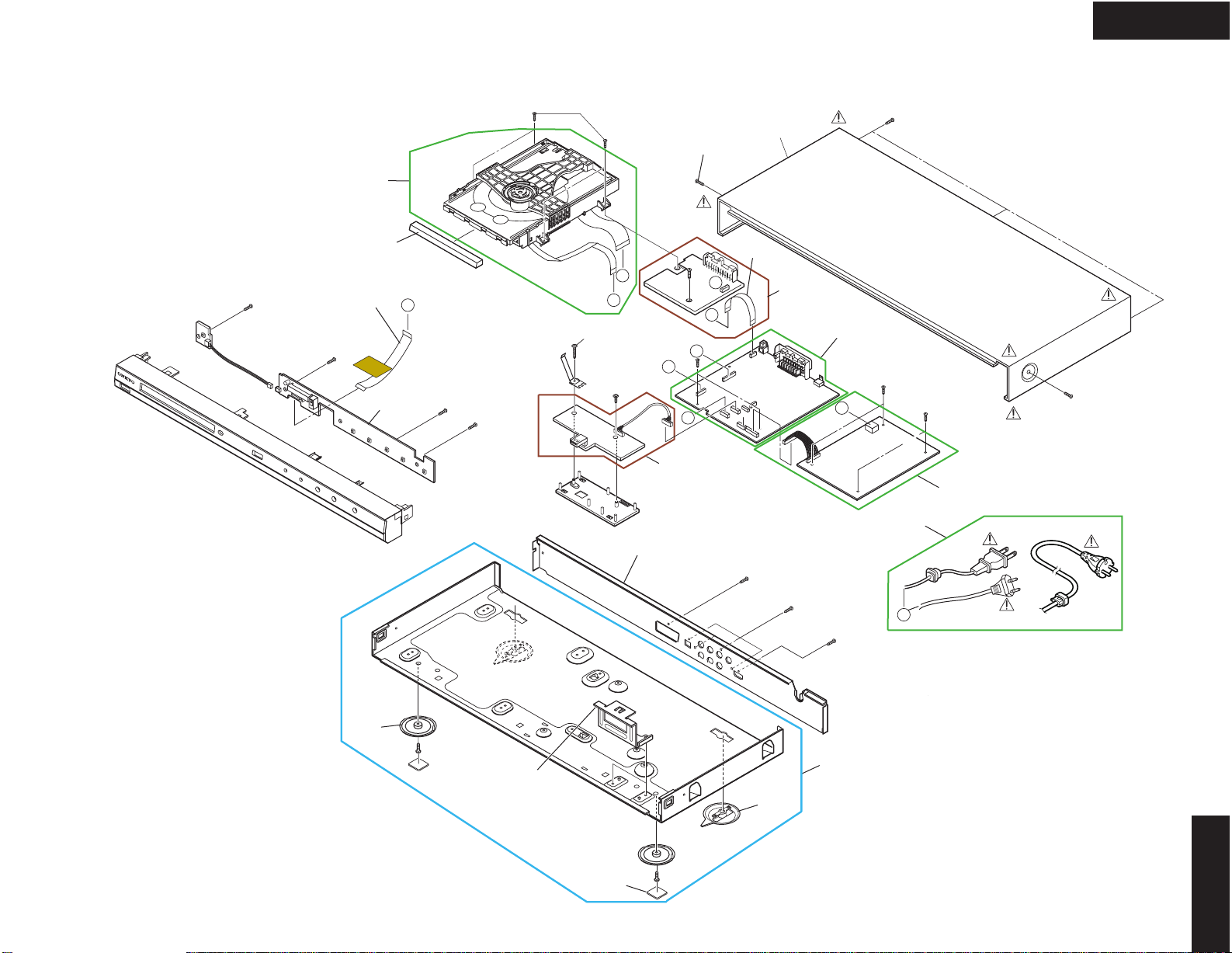
EXPLODED VIEW
CABINET AND MAIN FRAME SECTION
See mecha.
exploded view
283
Cable-1
EK
Y
D
Tape
1SZZR-0098J
4
C
461
B
460
Only used
Europe
B
C
x5
E
E
DV-SP406
250
Cable-2
A48
A43
TIMER
261A
x2
A50
Except used U.S.A.
262
320
A41
NIAM
D
261B
x2
A44
A
S
SPM
A47
300
A
DV-SP406
261
Page 3

EXPLODED VIEW-2
DECK MECHANISM SECTION (DP-12V)
A26
DV-SP406
026
016
010
Page 4
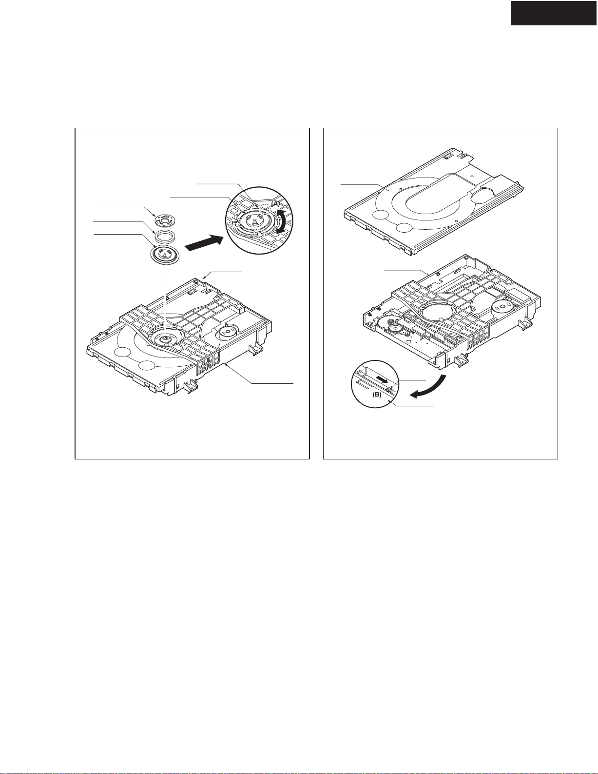
DECK MECHANISM DISASSEMBLY
DV-SP406
PLATE CLAMP
MAGNET CLAMP
CLAMP UPPER
MAIN BASE
DISC CLAMP ASSEMBLY
HOLDER
(Fig. A)
BASE MAIN
TRAY DISC
BASE MAIN
LEVER
BASE MAIN
BOTTOM SIDE VIEW
1-2 .GIF1-1 .GIF
1.MAIN BASE (FIG. 1-1)
1-1. Clamp Assembly Disc
1) Place the Clamp Assembly Disc as Fig. (A)
2) Lift up the Clamp Assembly Disc in direction of
arrow(A).
3) Separate the Clamp Assembly Disc from the
Holder Clamp.
1-1-1. Plate Clamp
1) Turn the Plate Clamp to counterclockwise
direction and then lift up the Plate Clamp.
1-1-2. Magnet Clamp
1-1-3. Clamp Upper
2.TRAY DISC (FIG. 2-1)
1) Insert and push a Driver in the emergency eject
hole(A) at the right side, or put the Driver on the
Lever(B) of the Gear Emergency and pull the
Lever(B) in direction of arrow so that the Tray
Disc is ejected about 15~20mm.
2) Pull the Tray Disc until it is separated from the
Base Main completely.
Page 5

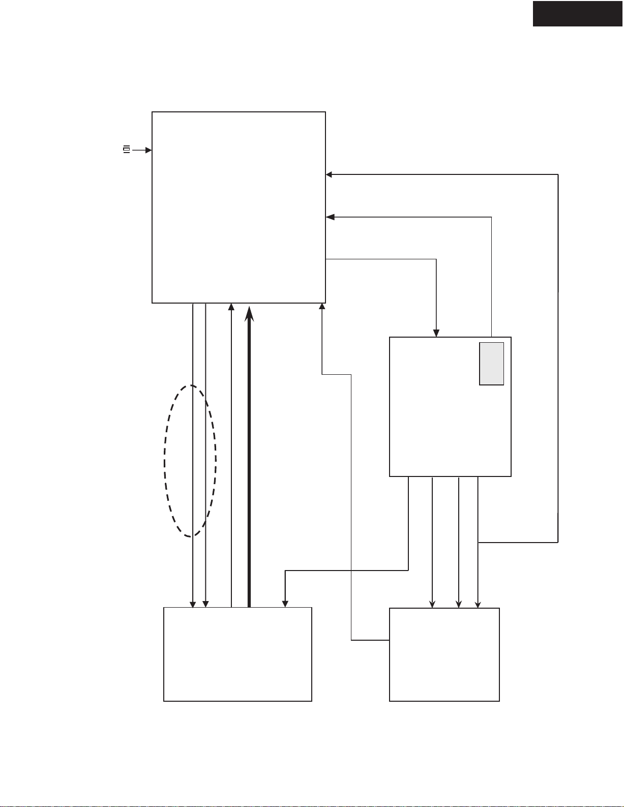
BLOCK DIAGRAMS-1
I
C
IR
Receive
ive
IC201
DP11
HDMI
JACK
H.P.D
TX[
TXC
OVERALL BLOCK DIAGRAM
DV-SP406
LOADING
MOTOR
DECK MECHANISM
5.6VA(M)
AC 90V~240V
50HZ/60Hz
DISC
SPINDLE
MOTOR
SLED
(FEEDING)
MOTOR
M
M
LOAD[+,-]
SLED[+,-]
IC201
AM5890S(5Ch)
Motor Drive
Voltage
detection
PICK
M
UP
DP11
SP[+,-]
FOCUS[+,-]
TRACK[+,-]
POWER
BOARD
A,B,C,D,RF
DVD :
CD : A,B,C,D,E,F,RF
MDI
CDLD,DVDLD,VC20
Pick-up
TRIN, TROUT
OP(+,-)
FMSO, DMSO,TRSO,FO
EN, TRCL
TROP
STBY,
PWR_CT
5V
3.3VA
5.6VA(M)
+12V
3.3V
OSE
L_H
IC201
3.3VA
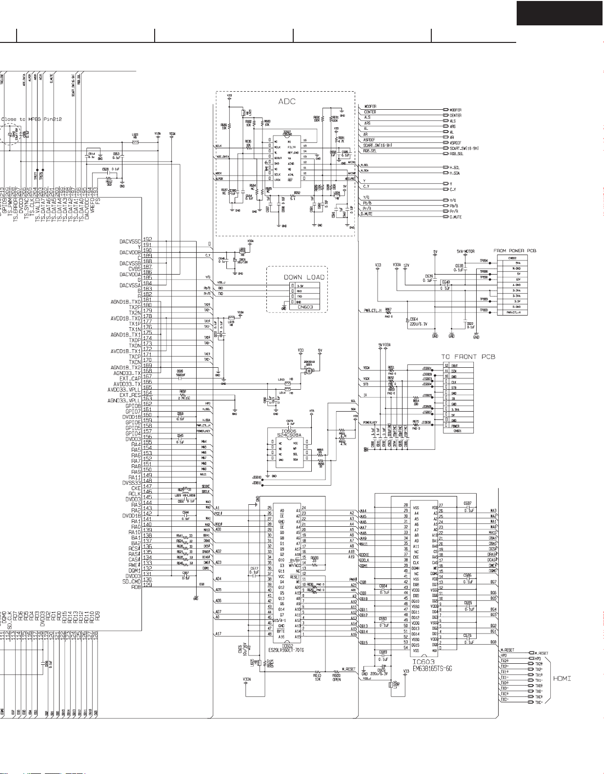
IC604
FLASH ROM
(1
6M)
MEMADD[0:19]
1.8VA
3.3VA
3.3V
IC603
64M bit
SDRAM
ROMADD[0:11]
RAMCAS
RAMRAS
RAMCS1
RAMCS0
RAMBA
MEMRD
MEMWR
ROMDATA[0:15]
RAMWE
RAMCKE
PC
ROMDAT[00:15]
LK
ACLK
ABCK
ALRCK
ADC_RST
30MH
z
IC607
CS6340
ADC
ADC_DATA
IC601
MT1389S
SO
IC604
KA741
OP-AMP
USBP,USB N
AT
I2CD
K
I2CCL
APWM_L +/=
APWM_R +/=
3.3VA
IC605
AT24C08A
EEPROM
12V
IC702
MC4580
OP-AMP
USB
JACK
L
R
RF+DSP+HDMI Tx + MPEG IC
RESET
1.8VA
FP DATA
FP STB
FP CL
K
ToTo FFroront IC
IR RCV
IR
Rece
RESET
Circuit
r
TX[
TXC
27MH
0-2 ]
R/Pr
CVBS
z
H.
±
±
HDMI
JA
SPDIF
OPTICAL
COAXIAL
G/Y
S-VIDEO OPTION
S-Video YC
B/Pb
scart(16:9)
5V
5V
IC701
VIDEO
BUFFER
RCG_SEL
EU only
DV-SP406
Page 6

BLOCK DIAGRAMS-2
POWER (SMPS) BLOCK DIAGRAM
DV-SP406
12V
OP AMP
LPF
5V
Video Buffer
LPF
Motor Drive IC 1.8V
5.6VA(M)
3.3VA
MPEG
Flash Memory
Remocon Receiver
LPF
3.3V
SDRAM
LED Clock,Driver
PWR CTL
RECTIFIER(14V)
RECTIFIER(5.6V)
TRANS
SWITCHING IC
RECTIFIER(3.3V)
FEED B.
AC100~240V
RECTIFIER
Page 7

BLOCK DIAGRAMS-3
D
DRI
IC(
C
9
0
1)
X
60
27MH
VID
OIn
terf
ace
MPEG & MEMORY BLOCK DIAGRAM
AUDIO
Interface
5.1CH
Option
IC605
EEPROM
IC603
64M bit
DV-SP406
SDRAM
Y_G_OUT
CVBS
R_SY_OUT
B_SC_OUT
VIDEO Interface
D_MUTE
AR
AUDIO Interface
AL
)
ASPDIF(Optica l
ASPDIF(COAXIAL)
Not used
CENTER
AR_R
AL_R
]
CLK
RAMCAS -
RAMRAS -
RAMADD[0:11]
I2Cdata I2
WOOFER
RAMDAT[00:15
RAMCS1 -
RESE T,WR-, CS0 -
MT1389S
IC601 (MPEG + DSP + RF)
RAMCS0 -
RAMCKE
RAMWE -
RAMBA
DA[0:15
AD[0:19 ]
1
X60
PCLK
]
USBP,USBN
z
27MH
IC604
FLASH MEMORY
CK
USB
JA
: EXCEL, SST, MX
(16 M )
ace
terf
EO In
VID
5V
Y_G_OUT
CVBS
R_SY_OUT
B_SC_OUT
IC701
VIDEO
VE
DRI
D
LE
IC901)
IC(
DIN ,DOUT
POWER, IR
ER
BUFF
H.P.D
TXC
TX [0-2 ] ,
HDMI
RESET
IC201
AM5890S(5Ch)
Motor Driver
Page 8
BLOCK DIAGRAMS-4
SERVO BLOCK DIAGRAM
L
X601
27MHz
X-TA
DV-SP406
IC601
ALPC
CDLD(LD01),DVDLD(LD02),V20
IOA
MTK1389S
ONE CHIP
DVDPLAYER
MDI1
SEL1
PICK
DVD : A,B,C,D,RF
CD : A,B,C,D,E,F,RF
,
TRIN,TROUT
FMSO,DMSO
TROPEN,
FOSO, TRSO
TRCLOSE,
STBY
RESET
Voltage
IC201
Motor Driver
AM5890S(5Ch)
-
P-
detection
OP+, OP-
UP
PICK
(IM)
T+, T-
F+, F-,
SL+, SL-
LOAD+,LOAD
M/D
SP+,S
(DP11)
Page 9
BLOCK DIAGRAMS-5
Pb
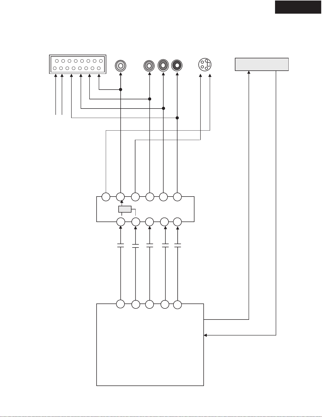
VIDEO & HDMI BLOCK DIAGRAM
DV-SP406
RGB_H
(EU only)
16_9_H
S-VIDEO
(Not used EU)
V.OUT
Y
Pb
Pr
HDMI JACK
R
CVBS
B
G
Pb
Y
Pr
SC
SY
±
±
H.P.D
TX[0- 2] , TXC
Y
Y
CVBS
C
Y_G
Pb_B_SC
Pr_R_S
Y
Y_C MIX
C
Y(G)
Mpeg IC
MT1389S
Pr(R)
Pb(B)
IC601
Page 10

DV-SP406
BLOCK DIAGRAMS-6
AUDIO BLOCK DIAGRAM
JACK
"
Not used
S/W
MUTE
AL_R
AR_R
CENTER
WOOFER
5.1ch
Connector
A Out "L"
A_L
A out "R
AMP
IC702
MC4580M
A_R
MUTEC
Audio
8DAC
DIF
COAXl_SP
Coaxial
Opti cal
Optical _SPDIF
IC601
MT1389S
MPEG
Serial Stereo
Digital Out
Page 11
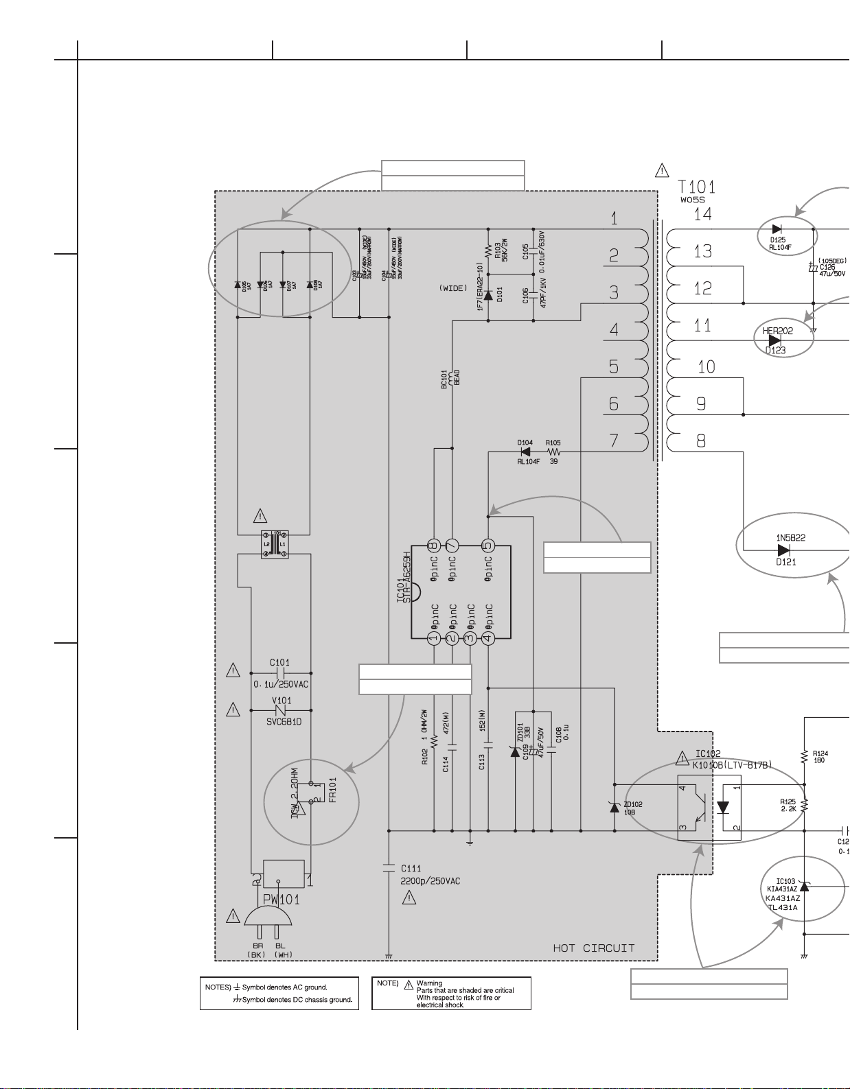
CIRCUIT DIAGRAMS-1
POWER (SMPS) CIRCUIT DIAGRAM
A
1
2
3
4
5
BCDEFGH
No Power
D105~D108 is Defective
3.3VA No Power
D121 or D122 are Defective
Switching Error
IC101is Defective
Switching Error
IC102,IC103 are Defective
No Power
FR101 is Defective
Page 12

DV-SP406
14VA No Power
D125 is Defective
5.6VA No Power
D123 is Defective
12V No Power
Q123 is Defective
5.0V No Power
Q126 is Defective
3.3V No Power
Q121 is Defective
WHEN SERVICING THIS CHASSIS, UNDER NO CIRCUMSTANCES SHOULD THE ORIGINAL DESIGN BE
MODIFIED OR ALTERED WITHOUT PERMISSION
FROM THE LG CORPORATION. ALL COMPONENTS
SHOULD BE REPLACED ONLY WITH TYPES IDENTICAL TO THOSE IN THE ORIGINAL CIRCUIT. SPECIAL
COMPONENTS ARE SHADED ON THE SCHEMATIC
FOR EASY IDENTIFICATION. THIS CIRCUIT DIAGRAM
MAY OCCASIONALLY DIFFER FROM THE ACTUAL
CIRCUIT USED. THIS WAY, IMPLEMENTATION OF THE
LATEST SAFETY AND PERFORMANCE IMPROVEMENT CHANGES INTO THE SET IS NOT DELAYED
UNTIL THE NEW SERVICE LITERATURE IS PRINTED.
1. Shaded( ) parts are critical for safety. Replace only
with specified part number.
2. Voltages are DC-measured with a digital voltmeter during Play mode.
IMPORTANT SAFETY NOTE :
Page 13
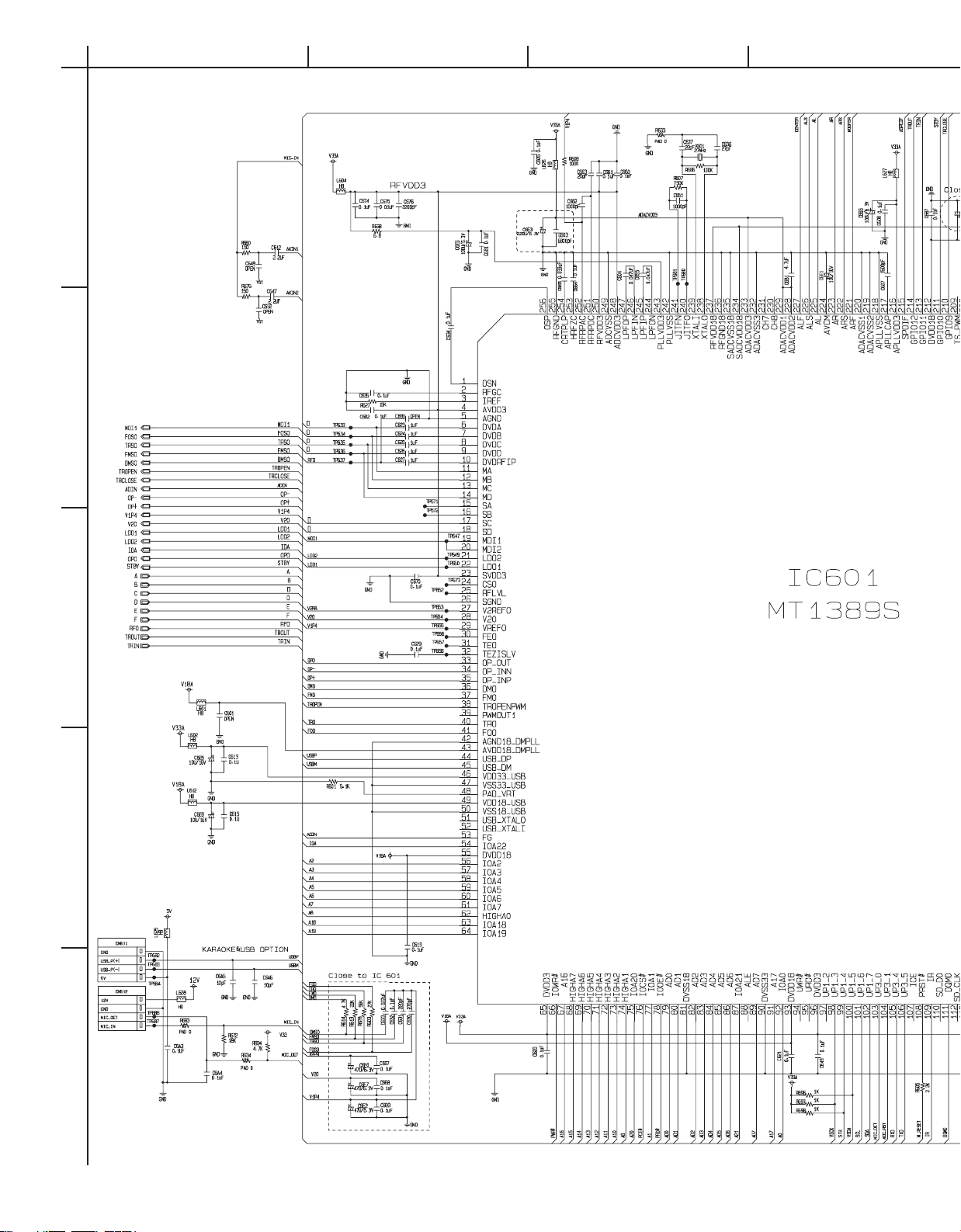
CIRCUIT DIAGRAM-2
MPEG CIRCUIT DIAGRAM
A
1
2
3
4
5
BCDEFGH
Page 14
DV-SP406
1
2
3
4
5
6
7
8
9
10
Page 15
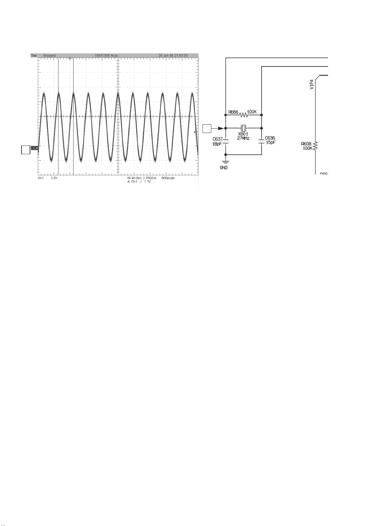
FIG 1-1
1
1
Page 16

FIG 3-1
10
11
12
13
11
IC601
10
12
13
TRIN
TROUT
TRCLOSE
TROPEN
Page 17

CIRCUIT DIAGRAMS-3
SERVO CIRCUIT DIAGRAM
A
1
2
3
4
5
BCDEFGH
Page 18

DV-SP406
Page 19

CIRCUIT DIAGRAMS-4
AV CIRCUIT DIAGRAM
A
1
2
3
4
5
BCDEFGH
Optical
Page 20

DV-SP406
Up coverter option
HDMI option
5.1CH option
Not Used
Page 21

DV-SP406
A
CIRCUIT DIAGRAMS-5
USB CIRCUIT DIAGRAM
1
Not Used
2
BCDE
Not Used
3
DV-SP406
4
Page 22

DV-SP406
A
CIRCUIT DIAGRAMS-6
KEY/TIMER CIRCUIT DIAGRAM
1
TIMER/ KEY CIRCUIT DIAGRAM
2
BCDE
POWER KEY CIRCUIT DIAGRAM
3
DV-SP406
4
Page 23

DV-SP406
A
SCHEMATIC DIAGRAM-7
SCART SECTION
1
2
BCDE
EU only
3
DV-SP406
4
Page 24

CIRCUIT V OL T AGE CHART -1
DV-SP406
MODE
PIN NO.
STOP PLAY
IC201(AM5869S)
1 1.392 1.397
2 1.705 1.637
3 1.375 1.436
4 1.393 1.396
5 1.243 1.238
6 0.01 0.01
7 0.02 0.02
8 5.589 5.53
9 0.001 0
10 0.001 0
11 2.729 2.771
12 2.729 2.687
13 2.733 2.686
14 2.733 2.757
15 2.739 2.701
16 2.739 2.725
17 2.734 3.725
18 2.734 1.656
19 5.598 5.55
20 3.277 3.253
21 5.598 5.54
22 0.001 0
23 1.395 1.734
24 3.275 3.251
25 5.574 5.51
26 1.392 1.391
27 1.392 1.391
28 0.019 3.197
29 0 0
30 0 0
IC601(MT1389S)
1 1.728 1.694
2 1.146 1.826
3 0.874 0.883
4 3.259 3.243
5 0.002 0.002
6 0.381 0.381
7 0.391 0.361
8 0.376 0.353
9 0.382 0.346
10 1.741 1.708
11 2.004 2.048
12 2.001 2.045
13 2.003 2.056
14 2.004 2.043
15 0.769 0.439
16 0.769 0.439
17 1.996 1.982
18 1.996 2.241
19 0 0.179
20 0 0.179
21 3.213 2.352
22 3.213 2.352
23 3.237 3.242
24 2.241 2.799
25 0.773 1.367
26 0.002 0.002
27 2.516 2.764
28 1.995 2.003
29 1.389 1.388
30 1.374 1.489
31 1.579 1.364
MODE
PIN NO.
32 1.578 1.359
33 2.431 1.824
34 2.593 1.828
35 2.196 1.684
36 1.391 1.834
37 1.391 1.466
38 0.008 0.009
39 1.391 1.391
40 1.388 1.382
41 1.387 1.422
42 0.002 0.001
43 1.859 1.856
44 0.011 0.008
45 0.011 0.008
46 3.281 3.272
47 0.002 0.002
48 0.819 0.794
49 1.859 1.854
50 0.002 0.002
51 0.971 0.864
52 0.971 0.717
53 3.261 0.017
54 3.241 0.022
55 1.848 1.851
56 1.954 2.257
57 1.884 2.054
58 1.947 2.239
59 1.694 1.604
60 1.785 1.783
61 1.816 2.346
62 1.997 1.652
63 0.127 0.125
64 0.012 0.015
65 3.285 3.277
66 3.285 3.276
67 1.393 1.093
68 1.759 1.806
69 1.251 3.043
70 2.245 3.006
71 1.249 3.131
72 0.305 0.712
73 2.466 1.706
74 2.759 1.332
75 0.011 0.013
76 0.011 0.013
77 2.079 1.895
78 0.011 0.012
79 1.369 1.523
80 1.705 1.803
81 0.002 0.002
82 0.585 0.854
83 0.971 0.956
84 1.561 1.616
85 1.547 1.469
86 1.683 0.974
87 0.021 0.024
88 1.171 1.127
89 1.368 1.117
90 0.002 0.002
91 0.025 0.024
92 1.998 1.846
93 1.876 1.828
94 3.254 3.257
STOP PLAY
MODE
PIN NO.
95 3.256 3.252
96 3.286 3.276
97 0.021 0.078
98 3.227 3.232
99 3.159 3.151
100 0.128 0.127
101 3.276 3.275
102 3.276 0
103 3.276 3.277
104 3.276 3.278
105 3.251 3.278
106 3.264 3.276
107 0.023 0.024
108 3.295 3.293
109 2.991 3.011
110 0.021 0.024
111 2.293 1.965
112 0.024 0.081
113 0.972 0.659
114 0.859 0.643
115 0.982 0.648
116 1.032 0.667
117 1.507 0.945
118 3.286 3.277
119 1.129 0.876
120 1.119 0.813
121 1.251 1.317
122 0.814 0.547
123 1.731 1.323
124 1.686 1.234
125 1.414 1.245
126 1.229 0.751
127 1.175 0.727
128 1.095 0.775
129 1.326 0.739
130 0.055 0.046
131 3.286 3.276
132 2.296 1.916
133 3.001 2.834
134 3.159 3.093
135 3.065 3.066
136 2.815 2.669
137 1.473 1.532
138 1.667 1.572
139 0.038 0.093
140 0.041 0.612
141 2.061 1.647
142 1.842 1.825
143 2.304 1.994
144 1.372 1.534
145 3.286 3.277
146 1.479 1.431
147 3.261 3.276
148 0.002 0.002
149 0.032 0.039
150 0.079 0.081
151 0.051 0.054
152 1.444 1.529
153 1.489 1.561
154 1.459 1.521
155 1.516 1.503
156 3.288 3.275
157 3.127 3.125
STOP PLAY
MODE
PIN NO.
158 3.266 3.258
159 4.82 4.82
160 1.842 1.829
161 4.84 4.84
162 0.021 0.017
163 0.002 0.002
164 1.331 1.33
165 3.099 3.086
166 3.099 3.086
167 0.345 0.208
168 0.001 0.001
169 0.001 0.001
170 0.001 0.001
171 0.003 0.004
172 1.842 1.831
173 0.002 0.001
174 0.002 0.002
175 0.001 0.001
176 0.002 0.003
177 0.002 0.002
178 1.845 1.832
179 0.002 0.002
180 0.002 0.002
181 0.002 0.002
182 0.637 0.032
183 0.701 0.034
184 0.003 0.003
185 0.496 0.127
186 3.251 3.237
187 2.614 2.567
188 0.003 0.002
189 0.676 0.659
190 3.251 3.238
191 0.498 0.281
192 0.002 0.002
193 1.212 1.207
194 1.289 1.203
195 3.251 3.239
196 0.016 0.018
197 0.016 0.018
198 0.024 0.022
199 0.024 0.022
200 0.024 0.023
201 0.128 3.248
202 0.027 0.023
203 0.024 1.523
204 0.023 1.608
205 0.023 1.635
206 2.915 1.321
207 3.266 3.256
208 0.023 0.024
209 0.023 0.024
210 0.018 0.021
211 0.019 3.218
212 1.831 1.829
213 0 0
214 2.945 2.936
215 1.539 1.533
216 3.241 3.251
217 1.892 1.698
218 0.002 0.002
219 0.002 0.002
220 0.002 0.002
STOP PLAY
Page 25

CIRCUIT V OL T AGE CHART -2
DV-SP406
MODE
PIN NO.
221 1.617 1.615
222 2.261 2.249
223 1.617 1.613
224 0 0
225 1.619 1.611
226 1.617 1.611
227 1.616 1.61
228 3.286 3.249
229 3.286 3.248
230 1.618 1.614
231 1.616 1.611
232 0.003 0.003
233 3.286 3.249
234 1.841 1.827
235 0.002 0.002
236 0.003 0.003
237 1.841 1.827
238 0.871 0.868
239 0.887 0.868
240 1.071 0.864
241 1.035 0.822
242 0.002 0.002
243 3.202 3.179
244 1.636 1.641
245 0.321 1.549
246 1.986 1.543
247 0.221 1.517
248 3.259 3.244
249 0.002 0.002
250 3.259 2.243
251 0.691 1.711
252 1.375 1.366
253 3.236 1.424
254 1.368 1.788
255 0.002 0.002
256 1.723 1.718
STOP PLAY
IC602(ES29LV160ET)
1 1.392 0.118
2 2.326 0.339
3 0.883 3.065
4 1.468 0.338
5 1.247 3.163
6 0.299 0.619
7 2.478 1.645
8 2.767 1.648
9 0.012 0.014
10 0.021 0.014
11 3.274 3.242
12 3.266 3.239
13 3.268 3.244
14 3.268 3.244
15 1.204 0.776
16 0.014 0.015
17 0.102 3.085
18 2.006 1.765
19 1.114 1.354
20 2.285 2.265
21 1.698 2.084
22 1.953 2.118
23 1.891 1.945
24 1.964 2.175
25 2.087 1.869
26 0.012 0.014
MODE
PIN NO.
27 0.002 0.001
28 0.012 0.013
29 1.376 1.561
30 0.528 0.202
31 1.706 1.766
32 0.436 0.775
33 0.961 1.188
34 0.441 0.587
35 0.588 1.134
36 0.365 0.729
37 3.267 3.241
38 1.383 1.442
39 0.432 1.291
40 1.505 1.536
41 0.413 0.847
42 1.637 1.527
43 0.447 1.028
44 1.339 1.142
45 2.012 1.846
46 0.001 0.001
47 0.001 0.001
48 0.014 0.026
STOP PLAY
IC603(HY57V64)
1 3.281 3.239
2 1.264 1.141
3 3.281 3.239
4 1.154 1.055
5 1.145 1.077
6 0.002 0
7 1.504 1.021
8 1.005 1.241
9 3.281 3.241
10 1.003 1.069
11 0.843 0.633
12 0.002 0
13 0.968 0.782
14 3.284 3.241
15 2.316 1.389
16 3.181 3.001
17 3.022 2.748
18 3.098 2.934
19 2.856 3.239
20 1.485 1.233
21 1.679 1.229
22 0.039 0.097
23 0.411 0.715
24 2.076 1.238
25 2.318 1.775
26 1.384 1.507
27 3.279 3.241
28 0.002 0.001
29 1.511 1.381
30 1.543 1.649
31 1.651 1.539
32 1.705 1.508
33 0.054 0.084
34 0.087 0.083
35 0.033 0.036
36 0 0
37 3.271 3.246
38 1.518 1.462
39 2.316 1.538
40 0 0
MODE
PIN NO.
41 0.002 0.001
42 1.339 0.796
43 3.278 3.267
44 1.117 0.885
45 1.217 1.009
46 0.002 0
47 1.231 1.144
48 1.473 0.745
49 3.279 3.267
50 1.742 1.127
51 1.786 1.281
52 0.002 0.001
53 0.828 1.051
54 0.002 0.001
STOP PLAY
IC606(S524C80D80-SCB1)
1 0.002 0
2 0.002 0
3 0.002 0
4 0.002 0
5 3.285 3.252
6 3.285 3.251
7 0.002 0
8 3.289 3.252
IC607(CS5340)
1 3.283 3.247
2 0.026 0.024
3 3.287 3.251
4 2.929 2.909
5 0.001 0.001
6 4.911 4.88
7 0.022 0.025
8 0.022 0.025
9 3.286 3.253
10 2.448 2.439
11 2.448 2.437
12 2.442 2.434
13 4.89 4.89
14 0.002 0
15 0.346 0.346
16 3.283 3.246
IC701(MM1692XVBE)
1 4.859 4.83
2 2.284 2.276
3 2.436 2.427
4 1.851 1.786
5 4.861 4.84
6 1.847 1.691
7 0.014 0.013
8 2.282 2.271
9 2.255 2.271
10 0.003 0.003
11 2.245 2.252
12 2.229 2.239
13 1.961 1.729
14 1.945 1.727
15 1.901 1.701
16 2.231 2.242
IC703(MC4580)
1 5.57 5.54
2 5.57 5.54
3 5.57 5.54
4 0.001 0.001
5 5.57 5.54
MODE
PIN NO.
STOP PLAY
6 5.57 5.54
7 5.57 5.54
8 12.21 12.13
Q201
Emitter 3.297 3.266
Collector 0.384 0.034
Base 3.237 3.221
Q202
Emitter 3.301 3.039
Collector 0.385 2.328
Base 3.242 2.305
Q205
Emitter 0 0.002
Collector 0.008 4.887
Base 0.651 0.019
Q206
Emitter 0 0.001
Collector 0 0.179
Base 3.234 0.022
Q207
Emitter 0 0.001
Collector 0 0.001
Base 0.008 4.839
Q208
Emitter 1.751 1.705
Collector 1.885 1.886
Base 2.482 2.461
Q601
Drain 3.296 3.271
Gate 3.107 3.093
Source 4.912 4.912
Q702
Emitter 0.001 0.001
Collector 0.005 0.002
Base 0.716 0.667
Q703
Emitter 3.269 3.257
Collector 3.239 3.115
Base 2.558 3.247
Q705
Emitter 0.001 0.001
Collector 0.005 0.003
Base 0.726 0.671
Q706
Emitter 0.002 0.002
Collector 0.082 0.083
Base 0.729 0.727
Q707
Emitter 0.001 0.001
Collector 0.085 0.081
Base 0.728 0.728
Q708
Emitter 0.001 0.001
Collector 0.034 0.035
Base 0.728 0.727
Q709
Emitter 2.271 2.254
Collector 4.86 4.86
Base 2.921 2.902
Page 26

CIRCUIT V OL T AGE CHART -3
DV-SP406
LOCATION SPEC
C642 33µ F/16V 1.858 0.002
C666 100µ F/6.3V 3.244 0.003
C6C1 10µ F/16V 12.251 0
C6C2 10µ F/16V 11.556 0
C6C6 10µ F/16V 3.257 0.001
C6C9 220µ F/16V 3.259 0.001
C6E0 47µ F/6.3V 2.758 0.001
C6E1 10µ F/16V 1.372 0.002
C6E2 47µ F/6.3V 1.396 0.002
C6E3 220µ F/6.3V 3.239 0.003
C6E4 220µ F/6.3V 3.268 0
C6E5 10µ F/16V 3.261 0.002
C6E6 100µ F/6.3V 3.165 0.003
C6E7 47µ F/6.3V 2.012 0.002
C6E8 10µ F/16V 1.852 0.002
C6E9 10µ F/16V 3.227 0.002
C202 220µ F/6.3V 3.257 0.001
C205 47µ F/6.3V 3.252 3.209
C206 47µ F/6.3V 3.252 2.254
C217 100µ F/6.3V 4.884 0.002
C220 220µ F/16V 5.515 0.016
C240 220µ F/6.3V 1.888 0.001
C242 10µ F/16V 3.266 0.002
C703 22µ F/16V 2.438 0.002
C704 47µ F/6.3V 4.859 0.002
C706 10µ F/16V 4.817 0.002
C728 47µ F/16V 12.256 0.145
C730 22µ F/16V 5.595 1.609
C731 47µ F/16V 5.599 0.002
C732 22µ F/16V 5.595 1.611
C734 22µ F/16V 5.595 0.006
C735 22µ F/16V 5.595 0.006
PLAY
+
-
Page 27

PRINTED CIRCUIT BOARD DIAGRAMS-1
MAIN P.C. BOARD
A
1
2
3
4
5
BCDEFGH
(TOP VIEW) (BOTTOM VIEW)
Page 28

DV-SP406
Page 29

DV-SP406
A
BCD
PRINTED CIRCUIT BOARD DIAGRAMS-2
POWER (SMPS) P.C.BOARD
1
2
NOTE)
Warning
Parts that are shaded are critical
with respect to risk of fire or
electrical shock.
3
(TOP VIEW)
4
5
(BOTTOM VIEW)
Page 30

DV-SP406
A
PRINTED CIRCUIT BOARD VIEW-3
1
CN902
1. POWER
2. GND
2
KEY BOARD
CN901
1. POWER
2. GND
3. +5V
4. 3.3VA
5. GND
6. IR
7. GND
8. STB
9. CLK
10. GND
11. DIN
12. DOUT
CN902
CN901
Component side view
BCDE
IC901
STANDBY/ON SWITCH BOARD
3
Component side view
DV-SP406
4
Page 31

DV-SP406
A
PRINTED CIRCUIT BOARD VIEW-4
1
USB TERMINAL BOARD
2
BCD
Except U.S.A. model
3
Component side view
4
5
Page 32

PRINTED CIRCUIT BOARD VIEW-5
DV-SP406
SCART TERMINAL PC BOARD
EU ONLY
Component side view
Page 33

IC BLOCK DIAGRAM/ TERMINAL DESCRIPTION
IC601 DVD IC MT1389S-1
PIN ASSIGNMENT
DV-SP406
Page 34

IC BLOCK DIAGRAM/ TERMINAL DESCRIPTION
IC601 DVD IC MT1389S-2
BLOCK DIAGRAM
DV-SP406
Page 35

IC BLOCK DIAGRAM/ TERMINAL DESCRIPTION
IC601 DVD IC MT1389S-3
PIN DESCRIPTION
Pin Definitions
DV-SP406
Page 36

IC BLOCK DIAGRAM/ TERMINAL DESCRIPTION
IC601 DVD IC MT1389S-4
PIN DESCRIPTION
DV-SP406
Page 37

IC BLOCK DIAGRAM/ TERMINAL DESCRIPTION
IC601 DVD IC MT1389S-5
PIN DESCRIPTION
DV-SP406
Page 38

IC BLOCK DIAGRAM/ TERMINAL DESCRIPTION
IC601 DVD IC MT1389S-6
PIN DESCRIPTION
DV-SP406
Page 39

IC BLOCK DIAGRAM/ TERMINAL DESCRIPTION
IC601 DVD IC MT1389S-7
PIN DESCRIPTION
DV-SP406
Page 40

IC BLOCK DIAGRAM/ TERMINAL DESCRIPTION
IC601 DVD IC MT1389S-8
PIN DESCRIPTION
DV-SP406
Page 41

IC BLOCK DIAGRAM/ TERMINAL DESCRIPTION
IC601 DVD IC MT1389S-9
PIN DESCRIPTION
DV-SP406
Page 42

IC BLOCK DIAGRAM/ TERMINAL DESCRIPTION
IC601 DVD IC MT1389S-10
PIN DESCRIPTION
DV-SP406
Page 43

IC BLOCK DIAGRAM/ TERMINAL DESCRIPTION
IC601 DVD IC MT1389S-11
PIN DESCRIPTION
DV-SP406
Page 44

IC BLOCK DIAGRAM/ TERMINAL DESCRIPTION
IC601 DVD IC MT1389S-12
PIN DESCRIPTION
DV-SP406
Page 45

IC BLOCK DIAGRAM/ TERMINAL DESCRIPTION
IC601 DVD IC MT1389S-13
PIN DESCRIPTION
DV-SP406
Page 46

IC BLOCK DIAGRAM/ TERMINAL DESCRIPTION
IC601 DVD IC MT1389S-14
PIN DESCRIPTION
DV-SP406
Page 47

IC BLOCK DIAGRAM/ TERMINAL DESCRIPTION
IC601 DVD IC MT1389S-15
PIN DESCRIPTION
DV-SP406
Page 48

DV-SP406
SERVICE PROCEDURES-1
PRODUCT SAFETY SERVICING GUIDELINES FOR DVD PRODUCTS
IMPORTANT SAFETY NOTICE
This manual was prepared for use only by properly trained audio-video service
technicians.
When servicing this product, under no circumstances should the original design be
modified or altered without permission from LG Corporation. All components should be
replaced only with types identical to those in the original circuit and their physical
location, wiring and lead dress must conform to original layout upon completion of
repairs.
Special components are also used to prevent x-radiation, shock and fire hazard.
These components are indicated by the letter “x” included in their component
designators and are required to maintain safe performance. No deviations are allowed
without prior approval by LG Corporation.
Circuit diagrams may occasionally differ from the actual circuit used. This way,
implementation of the latest safety and performance improvement changes into the set
are not delayed until the new service literature is printed.
CAUTION
customized installations without manufacturer’s approval. Unauthorized modifications
will not only void the warranty, but may lead to property damage or user injury.
Service work should be performed only after you are thoroughly familiar with these
safety checks and servicing guidelines.
: Do not attempt to modify this product in any way. Never perform
GRAPHIC SYMBOLS
The exclamation point within an equilateral triangle is intended to alert
the service personnel to important safety information in the service
literature.
The lightning flash with arrowhead symbol within an equilateral triangle
is intended to alert the service personnel to the presence of noninsulated
“dangerous voltage” that may be of sufficient magnitude to constitute a
risk of electric shock.
The pictorial representation of a fuse and its rating within an equilateral
triangle is intended to convey to the service personnel the following fuse
replacement caution notice:
CAUTION: FOR CONTINUED PROTECTION AGAINST RISK OF
FIRE, REPLACE ALL FUSES WITH THE SAME TYPE AND RATING
AS MARKED NEAR EACH FUSE.
SERVICE INFORMATION
While servicing, use an isolation transformer for protection from AC line shock. After the
original service problem has been corrected, make a check of the following:
FIRE AND SHOCK HAZARD
1. Be sure that all components are positioned to avoid a possibility of adjacent
component shorts. This is especially important on items trans-ported to and from the
repair shop.
2. Verify that all protective devices such as insulators, barriers, covers, shields, strain
reliefs, power supply cords, and other hardware have been reinstalled per the
original design. Be sure that the safety purpose of the polarized line plug has not
been defeated.
3. Soldering must be inspected to discover possible cold solder joints, solder splashes,
or sharp solder points. Be certain to remove all loose foreign particles.
4. Check for physical evidence of damage or deterioration to parts and components,
for frayed leads or damaged insulation (including the AC cord), and replace if
necessary.
5. No lead or component should touch a high current device or a resistor rated at 1 watt
or more. Lead tension around protruding metal surfaces must be avoided.
6. After reassembly of the set, always perform an AC leakage test on all exposed
metallic parts of the cabinet (the channel selector knobs, antenna terminals, handle
and screws) to be sure that set is safe to operate without danger of electrical shock.
DO NOT USE ALINE ISOLATION TRANSFORMER DURING THIS TEST. Use an
AC voltmeter having 5000 ohms per volt or more sensitivity in the following manner:
Connect a 1500 ohm, 10 watt resistor, paralleled by a .15 mfd 150V AC type
capacitor between a known good earth ground water pipe, conduit, etc.) and the
exposed metallic parts, one at a time. Measure the AC voltage across the
combination of 1500 ohm resistor and .15 mfd capacitor. Reverse the AC plug by
using a non-polarized adaptor and repeat AC voltage measurements for each
exposed metallic part. Voltage measured must not exceed 0.75 volts RMS. This
corresponds to 0.5 milliamp AC. Any value exceeding this limit constitutes a potential
shock hazard and must be corrected immediately.
Good Earth Ground
such as Water
Pipe, Conduit, eyc.
TIPS ON PROPER INSTALLATION
1. Never install any receiver in a closed-in recess, cubbyhole, or closely fitting shelf
space over, or close to, a heat duct, or in the path of heated air flow.
2. Avoid conditions of high humidity such as: outdoor patio installations where dew is a
factor, near steam radiators where steam leakage is a factor, etc.
3. Avoid placement where draperies may obstruct venting. The customer should also
avoid the use of decorative scarves or other coverings that might obstruct ventilation.
4. Wall- and shelf-mounted installations using a commercial mounting kit must follow
the factory-approved mounting instructions. A product mounted to a shelf or platform
must retain its original feet (or the equivalent thickness in spacers) to provide
adequate air flow across the bottom. Bolts or screws used for fasteners must not
touch any parts or wiring. Perform leakage tests on customized installations.
5. Caution customers against mounting a product on a sloping shelf or in a tilted
position, unless the receiver is properly secured.
6. A product on a roll-about cart should be stable in its mounting to the cart.
Caution the customer on the hazards of trying to roll a cart with small casters across
thresholds or deep pile carpets.
7. Caution customers against using extension cords. Explain that a forest of
extensions, sprouting from a single outlet, can lead to disastrous consequences to
home and family.
Place this probe
on each exposed
metal part.
Page 49

SERVICE PROCEDURE-2
SERVICING PRECAUTIONS
DV-SP406
CAUTION: Before servicing the DVD covered by this service
data and its supplements and addends, read and follow the
SAFETY PRECAUTIONS. NOTE: if unforeseen circumstances
create conflict between the following servicing precautions
and any of the safety precautions in this publication, always
follow the safety precautions.
Remember Safety First :
General Servicing Precautions
1. Always unplug the DVD AC power cord from the AC power
source before:
(1) Removing or reinstalling any component, circuit board,
module, or any other assembly.
(2) Disconnecting or reconnecting any internal electrical
plug or other electrical connection.
(3) Connecting a test substitute in parallel with an
electrolytic capacitor.
Caution: A wrong part substitution or incorrect polarity
installation of electrolytic capacitors may result in an
explosion hazard.
2. Do not spray chemicals on or near this DVD or any of its
assemblies.
3. Unless specified otherwise in this service data, clean
electrical contacts by applying an appropriate contact
cleaning solution to the contacts with a pipe cleaner, cottontipped swab, or comparable soft applicator.
Unless specified otherwise in this service data, lubrication of
contacts is not required.
4. Do not defeat any plug/socket B+ voltage interlocks with
which instruments covered by this service manual might be
equipped.
5. Do not apply AC power to this DVD and / or any of its
electrical assemblies unless all solid state device heat sinks
are correctly installed.
6. Always connect the test instrument ground lead to an
appropriate ground before connecting the test instrument
positive lead. Always remove the test instrument ground
lead last.
Insulation Checking Procedure
Disconnect the attachment plug from the AC outlet and turn
the power on. Connect an insulation resistance meter (500V)
to the blades of the attachment plug. The insulation resistance
between each blade of the attachment plug and accessible
conductive parts (Note 1) should be more than 1Mohm.
Note 1: Accessible Conductive Parts include Metal panels,
Input terminals, Earphone jacks,etc.
Electrostatically Sensitive (ES) Devices
Some semiconductor (solid state) devices can be damaged
easily by static electricity. Such components commonly are
called Electrostatically Sensitive (ES) Devices. Examples of
typical ES devices are integrated circuits and some field effect
transistors and semiconductor chip components.
The following techniques should be used to help reduce the
incidence of component damage caused by static electricity.
1. Immediately before handling any semiconductor component
or semiconductor-equipped assembly, drain off any
electrostatic charge on your body by touching a known earth
ground. Alternatively, obtain and wear a commercially
available discharging wrist strap device, which should be
removed for potential shock reasons prior to applying power
to the unit under test.
2. After removing an electrical assembly equipped with ES
devices, place the assembly on a conductive surface such
as aluminum foil, to prevent electrostatic charge buildup or
exposure of the assembly.
3. Use only a grounded-tip soldering iron to solder or unsolder
ES devices.
4. Use only an anti-static solder removal device. Some solder
removal devices not classified as “anti-static” can generate
electrical charges sufficient to damage ES devices.
5. Do not use freon-propelled chemicals. These can generate
an electrical charge sufficient to damage ES devices.
6. Do not remove a replacement ES device from its protective
package until immediately before you are ready to install it.
(Most replacement ES devices are packaged with leads
electrically shorted together by conductive foam, aluminum
foil, or comparable conductive material).
7. Immediately before removing the protective material from
the leads of a replacement ES device, touch the protective
material to the chassis or circuit assembly into which the
device will be installed.
Caution: Be sure no power is applied to the chassis or
circuit, and observe all other safety precautions.
8.Minimize bodily motions when handling unpackaged
replacement ES devices. (Normally harmless motion such
as the brushing together of your clothes fabric or the lifting
of your foot from a carpeted floor can generate static
electricity sufficient to damage an ES device.)
Page 50

THE PROCESS OF DISC DOWNLOAD-1
LANGUAGE
TV Aspect
Display mode
TV Output Select
16 : 9
Widescreen
YPbPr
Move
Select
Prev.
Please follow the below process to download a program with disc
1. Turn on the DVD-player.
(Note. Be sure that there is no disc in DVD-player)
2. Press “SETUP” button on Remote control.
3. Choose a “display” menu by using the cursor button and then choose a “TV Aspect” menu. And choose “16:9”
menu.
LANGUAGE
TV Aspect
Display mode
TV Output Select
16 : 9
Widescreen
YPbPr
DV-SP406
Prev.
Select
Move
4. Press the 1 --> 3 --> 9 --> 7 --> 1 --> 3 --> 9 (numerical button) --> Enter key on remote control to confirm the
system information.
5. Remember or write the model name.
SYSTEM INFORMATION
MODEL : ONKYO_DV_0V80F72E402MS
CHIP I.D : MT1389 S
SERVO VER. : Od66
MICOM VER. : V2.03
ChecSum :93e7
HDCP Key is Vaild : YES
Factory Reset.. Done. Plz Power Down!
6. Change the program file name of new version to the model name
Ex> New ver. program file->LG_DV_LV80F7FC10EMSMIS_V014.ROM
Model name -> LG_DV_LV81F7FC00EMS
Change New ver. program file like this --> LG_DV_LV81F7FC00EMSMIS.ROM
(NOTICE) You must add “MIS” at the end of model name
If you don”t change the file name like that, Disc download isn”t be worked.
Page 51

THE PROCESS OF DISC DOWNLOAD-2
6. Copy the changed file to a disc. (see page 3)
7. Insert the copied disc to DVD-player.
8. If the below picture appears on the screen.
9. After the below picture appears on the screen, Disc will emerge from DVD-player automatically.
Take the disc out of the DVD-player.
Firmware update Mode
Current Version : 2.03
Take off the disc and press PLAY key to upgrade
DV-SP406
Firmware update Mode
Current Version : 2.03
Upgrading : 0 to 100%
10. After Disc download is completed, DVD-player turns off and then turns on automatically.
11. Do it again the process 1, 2, 3, 4 to confirm the version.
Page 52

THE PROCESS OF DISC DOWNLOAD-3
1. Make the folder named RMTM0000.
2. Make the folder of the name of SCArLet into RMTM0000 folder.
3. Make the Firmware data in the SCArLet folder.
4. CD-R is made. (Writing new FW)
5. Setting the CD-R on the tray.
Region Managenent Test Mode
Current EEPROM_REGION_CODE 1
Press new region number(0-6) : _
Press PAUSE key to exist
DV-SP406
TV monitor
6. When the region code is changed, the figure from 0 to 6 is input by remote controller.
And PAUSE key is pushed.
7. Push the OPEN/CLOSE key, and pull out the CD-R.
8. Push STANDBY/ON key. After about 2 second, pull out a AC cord.
(The TV monitor screen becomes TOP menu display, and LCD display is disappear.)
Page 53

PARTS LIST DV-SP406
N
O
N
O
HIT-110/NI SPT-2X18AWG HIT UL/CSA 1800MM GP390 PVC TYBE 95MM
NSP: Not service part
<S>: Silver color
<B>: Black color
U.S. : North American
AUS : Australia
EU : Europe
MECHANICAL SECTION
DESTINATIO
LOCA.N
010 EAD34861101 Cable,FFC
016 EBR34880104 PCB Assembly
026 MJS31956302 Tray
A26 EAZ38311314 Deck Assembly,DVD
PART NO DESCRIPTION SPECIFICATION
AT10023270D01 270MM 1.00MM 23P WHITE AWM 2896 EUN SUNG
INDUSTRIAL CO.,LTD.
DP-12 FEEDING/LOADING -430mm
MOLD ABS XR-401 DVD dp-12 MOLD MD
DECK/MECHA DP-12V player (IN) IM Sled -430mm
DV-SP406
REMARKS
CABINET & MAIN FRAME SECTION
ASSEMBLY PARTS SECTION
DESTINATIO
<S>
<B>
EU, AUS only
EU, AUS only
<S> U.S.
<B> U.S.
<B> AUS
<B> EU
<S> EU
<S> AUS
<S> U.S.
<B> U.S.
AUS
EU
U.S.
AUS
EU
<S>
<B>
EU, AUS only
EU, AUS only
EU, AUS only
<S> U.S.
LOCA.N
PART NO DESCRIPTION SPECIFICATION
250 MBN42944901 Case, Top cover
250 MBN42944902 Case, Top cover
260 Chassis
261 MCQ32325001 Damper
261A MDP42944201 Foot
261B MDP42944501 Foot
262 MAZ32047801 Bracket
275 Plate,Ground
276 Holder
280 Panel Assembly,Front
280 Panel Assembly,Front
280 Panel Assembly,Front
280 Panel Assembly,Front
280 Panel Assembly,Front
280 Panel Assembly,Front
283 MJS42943101 Tray
300 6410RAHP03A Power Cord
300 6410RAHP01A Power Cord Assembly
300 6410RKHV03A Power Cord Assembly
300 6410RCHP04A Power Cord Assembly
320 MGC42944701 Panel,Rear
320 MGC42944703 Panel,Rear
320 MGC42944702 Panel,Rear
452 Screw,Customized
460 1SZZR-0098G Screw,Customized
460 1SZZR-0098H Screw,Customized
461 1SZZR-0098L Screw,Customized
462 Screw,Customized
463 Screw,Customized
465 Screw,Customized
467 Screw,Customized
470 Screw,Customized
A41 EBR50545802 PCB Assembly
A43 AAX59311403 Board Assembly
PRESS PCM 0.525 DV300_ONKYO PRESS TOP CASE
PRESS PCM 0.525 DV300_ONKYO PRESS TOP CASE
PRESS SECC 0.6 DV30-ON(ONKYO) PRESS MAIN(430mm)_WITH HDMI
CUTTING RUBBER DVD 07 DVD PLAYER OTHER FOOT(13*13*2t)
MOLD ABS HF-380 DVD DV300_ONKYO MOLD FRONT_FOOT_DECO
MOLD ABS HF-380 DVD DV300_ONKYO MOLD REAR_FOOT_DECO
PRESS SECC 1.0 DVD DV290 PRESS FRONT
PRESS STS 301 0.2mm MDD102 USB GROUND
MOLD HIPS 60HR DVD DV300 MOLD KARAOKE
DVD DV300H-ON ONKYO
DVD DV300-ON ONKYO
DVD DV300H-ON ONKYO
DVD DV300H-ON ONKYO
DVD DV302H-OE ONKYO
DVD DV302H-OE ONKYO
MOLD ABS TR558 DVD DV300_ONKYO MOLD DOOR_TRAY
SPT-2/18AWG/BLK/NM/1.8M/BLK A122 GP390-3S-CS 1.8M 120MM 125V 15A
SPT-2 2XAWG18 BLACK UL CSA N HARNESSINDO TUNGGAL / HIT , PT
AU10S3+H03VVH2-F 2X0.75MM2 NM to PS PVC LEAD FREE/1.8M/BLK (with
tube) AU10S2 GP390-3S-CS 1.8M 95MM 250V 10A H03VVH2-F 2X0.75MM2
BLACK SAA N VOLEX (ASIA) PTE LTD.
HIT-101/H03VVH2-F/2X0.75MM2/70℃/BK/GP-390-3S HIT-101 GP-390-3S-CS
1.8M 95MM 250V 2.5A H03VVH2-F 2X0.75MM2 BLACK CEU N HIT
ELECTRONICS INDONESIA PT
PRESS SECC 0.6 DVD DV300_ONKYO PRESS REAR_PANEL
PRESS SECC 0.6 DVD DV300H_ON(ONKYO_ASIA) PRESS REAR_PANEL
PRESS SECC 0.6 DVD DV300H_ON(ONKYO_EUROPE) PRESS REAR_PANEL
1SZZR-0098A BH + 3MM 10MM MSWR FZY SIN JIN BOLT IND CO.
1SZZR-0098G FH + 3MM 8MM MSWR FZW SIN JIN BOLT IND CO.
- + 3MM 8MM MSWR FZW SIN JIN BOLT IND CO.
- + 3MM 16MM MSWR NI PLT SIN JIN BOLT IND CO.
1SZZ0098J BH + 3MM 6.5MM MSWR FZY SIN JIN BOLT IND CO.
1SZZR-0098G FH + 3MM 8MM MSWR FZW SIN JIN BOLT IND CO.
1SZZR-0097K BH + 3MM 10MM MSWR FZB SIN JIN BOLT IND CO.
- + 3MM 8MM MSWR FZB SIN JIN BOLT IND CO.
BZN BK (CR +3) SPECIAL + 3MM 6MM SWRCH FZB
DV300 ONKYO USB _
DVD DV300H-ON ONKYO
DV-SP406
REMARKS
NSP
NSP
NSP
NSP
NSP
NSP
NSP
NSP
NSP
NSP
NSP
NSP
NSP
NSP
NSP
Page 54

<B> U.S.
N
O
N
O
EU, AUS only
EU, AUS only
U.S.
AUS
EU
U.S.
EU, AUS only
EU only
A43 AAX59311401 Board Assembly
A43 AAX59311404 Board Assembly
A43 AAX59311402 Board Assembly
A44 ADV59279101 Frame Assembly
A44 ADV59279103 Frame Assembly
A44 ADV59279102 Frame Assembly
A47 EBR42200722 PCB Assembly,Power
A47 EBR42200721 PCB Assembly,Power
A48 EBR42778911 PCB Assembly
A50 EBR50460302 PCB Assembly
DVD DV302H-OE ONKYO
DVD DV302H-OE ONKYO
DVD DV300H-ON ONKYO
DVD DV300H-ON(ONKYO) DVD DV300H-ON(ONKYO) DVD DV300H-ON(ONKYO) DV300'S SMPS IN Narrow Total Ass'y
DV300'S SMPS IN WIDE Total Ass'y
DV300'S Scart PCB ASSY IN .
08 DVD-P ONKYO TIMER IN
PACKING SECTION
DESTINATIO
U.S.
AUS
EU
U.S.
EU, AUS only
U.S.
EU, AUS only
U.S.
EU, AUS only
U.S.
AUS
EU
LOCA.N
801 AFN52750428 Manual Assembly,Owners
801 AFN52750430 Manual Assembly,Owners
801 AFN52750429 Manual Assembly,Owners
802 MAY46749483 Box,Master
803 MFZ47272603 Packing
804 Bag,Vinyl
806 6850R-PAA2E Cable,Assembly
808 Dry Cell Battery
810 6851R-0081B Accessory Assembly
810 6851R-0074B Accessory Assembly
811 6850R-PAA8F Cable,Assembly
811 6850R-PAA2F Cable,Assembly
812 6850R-PBA8H Cable,Assembly
812 6850R-PBA2H Cable,Assembly
900 AKB57498901 Remote Controller Assembly
A46 EBR42880773 Option Code Assembly
A46 EBR42880775 Option Code Assembly
A46 EBR42880774 Option Code Assembly
ELECTRICAL SECTION
DESTINATIO
EU only
EU, AUS only
EU only
EU, AUS only
LOCA.N
CABLE1 EAD42078701 Cable,FFC
CABLE2 EAD35665101 Cable,FFC
CN201 6630XE00123 Connector,FFC/FPC/PIC
CN202 6630XE00109 Connector,FFC/FPC/PIC
CN601 6630R-FB10L Connector,FFC/FPC/PIC
CN602 561-711J Connector,Wafer
CN611 561-711D Connector,Wafer
CN705 6630XE00112 Connector,FFC/FPC/PIC
CN801 EAD42070202 Harness,Single
CN901 6630R-FB10L Connector,FFC/FPC/PIC
CN902 EAD36507207 Harness,Single
PART NO DESCRIPTION SPECIFICATION
DVD DV300H-ON.BUSAOOK/S ASS'Y
DVD DV300H-OP.BAUSOOK/S ASS'Y
DVD DV302H-OE.BDEUOOK/S ASS'Y
BOX SW3 515 119 293 2 COLOR DV302H-OP BAUSOOS SWW3-A ONKYO
CUTTING EPS DVD DV300_ONKYO 45 .
CUTTING HDPE 430 500 0.5 DVD9000
RCA PLUG RCA PLUG 1.2M 1P BLACK PVC AWG26X1C+S N SE IL
ELECTRONICS
AAA(R03) 1PAIR 1.5V 50MAH AAA STC CORPORATION
VCR LGEIN 1WAY YELLOW 1.8M +2WAY RED_WHITE 1.8M
HIT_HY_SEIL_DT FREE OF HAZARDOS
VCR LGEIN 1WAY YELLOW 1.2M + 2WAY R/W 1.2M FREE OF CD_PB_HG
HY_HIT_DT_SEIL
HAV-10001-01 RCA PLUG(3.2) RCA PLUG(3.2) 1.8M 1P BLACK PVC
AWG26X1C+S N HYO SUNG ELECT.CO.,LTD
RCA PLUG RCA PLUG 1.2M 1P YELLOW PVC AWG26X1C+S N SE IL
ELECTRONICS
HAV-10004-01 RCA PLUG(3.2) RCA PLUG(3.2) 1.8M 2P BLACK PVC
AWG26X1C+SX2P N HYO SUNG ELECT.CO.,LTD
RCA PLUG RCA PLUG 1.2M 2P RED/WHITE PVC AWG26X1C+S N SE IL
ELECTRONICS
U2 DV3 ONKYO BLACK
DV300H-ON.BUSAOOK . .
DV302H-OP.BAUSOOK . .
DV302H-OE.BDEUOOK . .
PART NO DESCRIPTION SPECIFICATION
AT10012180D02 180MM 1.00MM 12P WHITE UL2896 (DV398) EUN SUNG
INDUSTRIAL CO.,LTD.
AT10012060C03 60MM 1.00MM 12P WHITE UL 2896 DV286K-EM EUN SUNG
INDUSTRIAL CO.,LTD.
04-6232-023-010-000 23P 1.00MM FFC/FPC STRAIGHT TOP SMD TP
NON_LOCKING - KYOCERA ELCO
04-6232-009-010-000 9P 1.00MM FFC/FPC STRAIGHT TOP SMD TP
NON_LOCKING - KYOCERA ELCO
00-6232-012-006-800 12P 1.00MM FFC/FPC STRAIGHT TOP SMD TP
NON_LOCKING - KYOCERA ELCO
GIL-S-10P-S2T2-EF 10P 2.00MM 1R STRAIGHT DIP ST LIGHT BROWN - LS
CABLE
GIL-S-04P-S2T2-EF 4P 2.00MM 1R STRAIGHT DIP ST LIGHT BROWN JE500-B1.0-T12 12P 1.00MM FFC STRAIGHT TOP SMD TP NON_LOCKING -
JAE EUN ELECTRONIC CO., LTD
4P-70MM SHIELD (DV398) GIL-S 9073-ST 70MM 2.00MM 4P UL1061 AWG26 N
SHIELD HYUN SEUNG ELECTRONICS (TAI CHANG) CO.LTD.
00-6232-012-006-800 12P 1.00MM FFC/FPC STRAIGHT TOP SMD TP
NON_LOCKING - KYOCERA ELCO
2P-150MM (DV200) TJC19-02Y/GIL-S-02 SANW-02Y 150MM 2.00MM 2P AWG24
(BLUE,GRAY) N - HIT ELECTRO MECHANICS INDONESIA PT
DV-SP406
REMARKS
NSP
NSP
DV-SP406
REMARKS
Page 55

TL431 MAX12V 3.3V 600MW TO92 TP 3P UNISONIC TECHNOLOGIES CO
EU only
U.S., AUS only
EU only
EU, AUS only
EU only
CN903 561-712B Connector,Wafer
D104, D125 0DR104009BA Diode,Rectifier
D105, D106, D107,
D108
0DRRE00203A Diode,Rectifier
D121 0DR158220AA Diode,Schottky
D123 0DR202000AB Diode,Rectifier
DIG901 6301R2U017Q LED Assembly
FR101 0RM0221K634 Resistor,Cement
IC101 EAN34789801 IC,PWM Controller
IC102 6500RDB011B Sensor,Position
IC103 0IPMGUC004B IC,LDO Voltage Regulator
JK301 6612M00003B Jack,Scart
JK701 6612K00003D Jack,Fiber Optic
JK702 EAG40564001 Jack,Complex
JK702 EAG41396501 Jack,RCA
JK705 EAG40562101 Connector,DSUB
JK803 EAG35130502 Connector,USB
P101 6631R-E078Q Harness,Single
P3701 6630R-FB10L Connector,FFC/FPC/PIC
PW101 6630V90108A Connector,Wafer
Q121 0TR127109AA TR,Bipolar
Q123 0TR320309AA TR,Bipolar
Q126 0TR320509AB Transistor Assembly
GIL-S-02P-S2L2-EF 2P 2.00MM 1R ANGLE DIP ST LIGHT BROWN RL104F 400V 1.3V 5UA 30A 150NSEC A405 TP 2P 1 RECTRON CO. LTD
1A7 600V 1.1V 5UA 25A - R1 TP 2P 1 RECTRON CO. LTD
1N5822 950MV 40V 3A 1NSEC 250pF 1.1W DO201 TP 2P 1 RECTRON CO. LTD
HER202 100V 1V 5UA 60A 50NSEC DO15 TP 2P 1 RECTRON CO. LTD
GYXS-2511CG LED CLOCK BRIGHT LED UNIVERSAL 8m GUO JIAN (QING
DAO) JIN SU ZHI PIN CO.,LTD
ICW02M22R20J 2.2OHM 5% 2W 27X10X9.5MM 5MM RADIAL BK SMART
ELECTRONICS INC.
STR-A6259H 12.9V TO 15.7V 10V 1.35W DIP ST 8P SANKEN ELECTRIC
CO.,LTD.
K1010B 5V DIP BK 4P 4PIN PHOTOCOUPLER COSMO CORPORATION
RGB-16B 21P 21P/1C 3.81MM ANGLE DIP TR - ZHEJIANG YUQIU
ELECTRONIC CO.,LTD
JST1164 3P TX 2.54MM ANGLE 13.2MBPS DIP ST BRASS 7V - JST
MANUFACTURING CO., LTD.
RCA/DIN-709A-00-01. 16P RCA/DIN, BK/RE/WH/YL, DIN/GN/BL/RD 15MM
ANGLE DIP TR BK/RE/WH/YL, DIN/GN/BL/RD ZHEJIANG YUQIU
ELECTRONIC CO.,LTD
RCA-707A-00-01 15.0MM 2RX4C ANGLE TR BK/RD/WH/YL, None/GN/BL/RD
ZHEJIANG YUQIU ELECTRONIC CO.,LTD
HMR24-AK5210 HDMI 19P 1.5MM ANGLE FEMALE DIP TR NON_LOCKING -
ADVANCED - CONNECTEK,INC.
U250FD004S113BY A 1P 2.00/2.50MM ANGLE DIP TR 2P Normal Type YUQIU
MACHINERY & ELECTRONIC
GIL-S10/9073 10ST 60mm GIL-S-10 9073-10 ST 60mm 2.00MM 10P UL1061
AWG26 N . DONGJI ELECTRONICS
00-6232-012-006-800 12P 1.00MM FFC/FPC STRAIGHT TOP SMD TP
NON_LOCKING - KYOCERA ELCO
JE202-2L-03 2P 3.96MM 1R ANGLE DIP ST WHITE - JAE EUN ELECTRONIC
CO., LTD
KTA1271Y PNP -5V -35V -30V -0.8A -0.0000001A 160TO320 625MW TO92 TP 3P
KEC CORPERATION
KTC3203 NPN 5V 35V 30V 800MA 100NA 100TO320 625MW TO92 TP 3P KEC
CORPERATION
KTC3205-Y(KTC2236A) KTC3205-Y(KTC2236A) TP KEC TO92L NPN KEC
CORPERATION
.,
Page 56

DV-SP406
ONKYO CORPORATION
Sales & Product Planning Div. : 2-1, Nisshin-cho, Neyagawa-shi, OSAKA 572-8540, JAPAN
Tel: 072-831-8023 Fax: 072-831-8163
ONKYO U.S.A. CORPORATION
18 Park Way, Upper Saddle River, N.J. 07458, U.S.A.
Tel: 201-785-2600 Fax: 201-785-2650 http://www.us.onkyo.com/
ONKYO EUROPE ELECTRONICS GmbH
Liegnitzerstrasse 6, 82194 Groebenzell, GERMANY
Tel: +49-8142-4401-0 Fax: +49-8142-4401-555 http://www.eu.onkyo.com/
ONKYO EUROPE UK Office
Suite 1, Gregories Court, Gregories Road, Beaconsfield, Buckinghamshire, HP9 1HQ
UNITED KINGDOM Tel: +44-(0)1494-681515 Fax: +44(0)-1494-680452
ONKYO CHINA LIMITED
Units 2102-2107, Metroplaza Tower I, 223 Hing Fong Road, Kwai Chung,
N.T., HONG KONG Tel: 852-2429-3118 Fax: 852-2428-9039
http://www.ch.onkyo.com/
HOMEPAGE
http://www.onkyo.com/
 Loading...