

Page 1

DLV-100
Ref. No. 3701
SERVICE MANUAL
Digital Light Processing Projector
MODEL
E
L
C
N
A
C
R
E
T
CT
N
LE
E
SE
U
N
E
M
ADJUST
AUTO
DLV-100
CESS
PC CARD AC
CE
OUR
S
BY
STAND
ON/
OWER
P
TUS
STA
Nov, 2001
INPUT
100 - 120 / 200 - 240 V AC, 50 / 60 HzUUD
SAFETY-RELATED COMPONENT
WARNING!!
COMPONENTS IDENTIFIED BY MARK ON THE
SCHEMATIC DIAGRAM AND IN THE PARTS LIST ARE
CRITICAL FOR RISK OF FIRE AND ELECTRIC SHOCK.
REPLACE THESE COMPONENTS WITH ONKYO
PARTS WHOSE PART NUMBERS APPEAR AS SHOWN
IN THIS MANUAL.
MAKE LEAKAGE-CURRENT OR RESISTANCE
MEASUREMENTS TO DETERMINE THAT EXPOSED
PARTS ARE ACCEPTABLY INSULATED FROM THE
SUPPLY CIRCUIT BEFORE RETURNING THE
APPLIANCE TO THE CUSTOMER.
Page 2

1. Application
This specification sheet applies for DLV-100.
Model DLV-100
NEC Model code 01152009
2. General
2. General
2. General2. General
2.1 Operation temperature range
+5 ~ +35 degree C (Humidity 20-80%RH, not in the dewfall.)
2.2 Storage temperature range
-10 ~ +50 degree C
2.3 Power source
100 ~ 120 VAC / 200 ~ 240 VAC +/-10%, 50 / 60 Hz
2.4 Input Current
2.2/1.1A (MAX.)
2.5 Inspection condition
Inspection shall be done by AC120V / 60 Hz unless no rule is specified.
As for the projection condition, t h e screen is perpendicularly installed to the set and the
projection screen is in WIDE condition of 60 inches. When test, inspector shall be 2 +/- 0.3 m
away from the screen.
DLV-100
Screen
Inspector
2±0.3 m
Fig. 1 Condition
3. Main parts specifications
3. Main parts specifications
3. Main parts specifications3. Main parts specifications
3.1 DMD panel
Single Chip Digital Micromirror Device(DMD)
1024
3.2 Lens
x 768 pixels
Manual zoom and focus
F-no.=2.61~2.84, f=28.35~34.02mm
3.3 Lamp
135W DC Lamp
Average lifetime 1,000H
The definition of average lifetime is the time that light becomes half with the continuous
lighting-up.
(Notes)
The lamp bulb can be ruptured, while using a projector.
When the lamp bulb is ruptured, there is a small crack and pieces of glass, which may be
scattered in the lamp case.
Page 3

4. Electric specifications
4. Electric specifications
4. Electric specifications4. Electric specifications
4.1 Input signal band width
RGB 80MHz
Video 6.5MHz
4.2 Graduation
256 grade full color (16,777,216 color)
4.3 Display resolution
NTSC/PAL/YCbCr 550TV lines
SECAM 300TV lines
RGB 1024dots(H)×768dots(V)
4.4 Input terminal
RGB 1 input: Mini D-SUB 15pin
VIDEO 1 input: RCA
S-VIDEO 1 input: DIN 4pin
Audio 1 input: Stereo mini jack
PC Control 1 input: DIN 8pin
USB 1 input: Type A
PC Card 1 input: CompactFlash
4.5 PC Card Viewer
This Viewer can disp lay t he JP EG/BM P ima ge whic h is pres erved i n Compa ctF las h (CF ).
CF correspond to SanDisk CF 128Mbytes media.
4.6 Y/C Separation
NTSC/PAL
4.7 Input signal (RGB)
Horizontal Freq. 15 ~ 100KHz(RGB: 24KHz or over)
Vertical freq. 50 ~ 120Hz
Pixel clock freq. Less than 100MHz
Capable resolution UXGA 1600dot(H)×1200dot(V) Max.
Sync system Separate Sync/Composite Sync/Sync on G
4.8 Input signal level
RGBHV Input R,G,B 0.7Vp-p / 75ohm positive
VIDEO 1.0Vp-p / 75 ohm
S-VIDEO Y: 1.0Vp-p / 75 ohm
C: 0.283Vp-p / 75 ohm
AUDIO 0.5Vrms / 22 K ohm
4.9 Audio output
1W monaural Speaker
DLV-100
YCbCr:shares with the RGB terminal
Y 1.0Vp-p / 75ohm positive
Cb,Cr(Pb,Pr) 0.7Vp-p / 75ohm
H/V Sync 4.0Vp-p / TTL posi./nega
Composite Sync 4.0Vp-p / TTL posi./nega
Sync on G 0.3Vp-p / 75 ohm negative
Page 4

4.10 On Screen Display
1. Pull down menu
Basic/Custom menu <> Advanced menu
2. Multilingual menu
English / French /German / Italian / Japanese / Spanish / Swedish
4.11 Remote
Palm type remote unit
4.12 Input current
2.2A 100 ~ 120VAC/1.1A 200 ~ 240VAC
4.13 Plug & Play data
Tab.1 EDID data
00001
12
23
11
22
00
00
0000
00 FF FF FF FF FF FF 00 38 A3 D3 00 01 00 00 00
10
10
1010
27 0B 01 02 0E 00 00 78 0A 34 70 95 59 4F 88 26
20
20
2020
15 4A 53 FF FF 80 31 59 45 59 61 59 71 59 81 4F
30
30
3030
81 99 A9 4F 01 01 EA 24 00 60 41 00 28 30 30 60
40
40
4040
13 00 00 00 00 00 00 1E F9 15 20 F8 30 58 1F 20
50
50
5050
20 40 13 00 00 00 00 00 00 1E 00 00 00 FD 00 32
60
60
6060
78 0F 64 0A 00 0A 20 20 20 20 20 20 00 00 00 FC
70
70
7070
00 4F 4E 4B 59 4F 20 44 4C 56 31 30 30 0A 00 E2
34
45
33
44
56
67
55
66
78
89
77
88
9A
AB
99
AA
BC
CD
BB
CC
DE
EF
DD
EE
DLV-100
F
FF
4.14 Safety test
(1)Dielectric strength test
By the test vessel, under the condition of main power supply ON,
Apply AC voltage of 1500V(+50/-0) ,at 50Hz or 60Hz for 1.5~2 second between power supply
circuit part(AC) and exposure metal part.
No insulation destruction, catching fire, and so on is allowed.
(2) Insulation resist ance test
Measure insulation resistance between power supply circuit part(AC) and exposure metal
part (FG) under the condition of main power ON(Stand By mode) by using 500V insulate
ohmmeter.
Insulation resistance shall be more than 50M ohm.
(3)Leakage electric current test
Measure leakage electric current by the leakage ammeter under the condition of main power
supply ON (Standby condition). The measurement impedance should be measured by
the build in resistor of 1.5KΩ, with the bypass capacitor of 0.15μF.
The leakage electric current should be less than 2mA each.
4.15 Signal table
Refer to Tab.2.
Page 5
5. Optical specifications
5. Optical specifications
5. Optical specifications5. Optical specifications
5.1 Brightness
Normal : 630 ANSI lumens minimum
High Brightness : 750 ANSI lumens minimum
(It contains 5 % of measurement tolerance.)
5.2 Contrast ratio
700 : 1 typical
(It contains 20 % of measurement tolerance.)
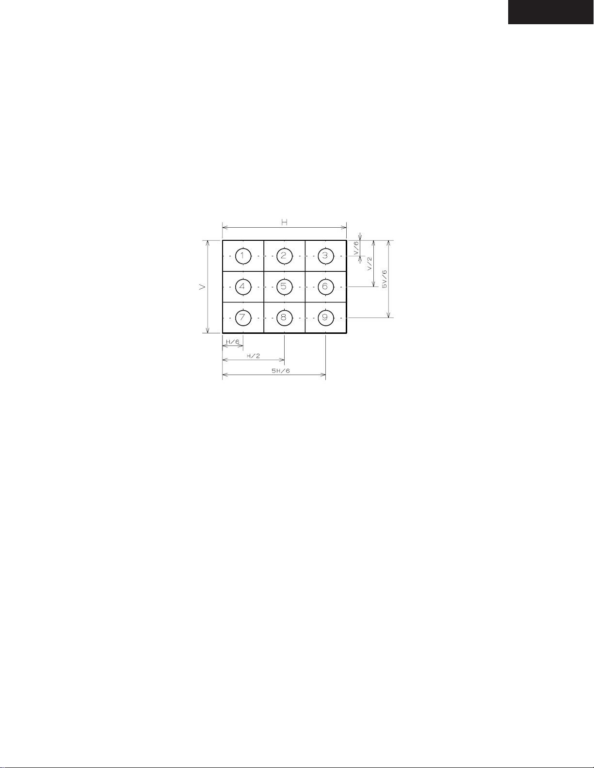
5.3 Relative illumination
More than 70%
On the screen which is shown in figure 2, apply following formula with condition of
Aj as the illumination of point j.
Relative illumination = ( A1 + A3 + A7 + A9 ) / ( 4 x A5 ) x 100 [%]
DLV-100
Fig.2 The measurement point
5.4 Chromaticity
x=0.234 – 0.344(0.289 +/- 0.055)
y=0.269 – 0.379(0.324 +/- 0.055)
5.5 Throwing angle
14.3 degree(+/- 5%)
5.6 Projection size
Min. 30 inch / 1.16 m (wide)
Max. 200 inch / 9.67 m (tele)
(For the details, refers to Tab.3.)
5.7 Geometry distortion
Less than 1.11%
5.8 Pixel defects and blemishes
1. No adjacent dark pixels.
2. No bright pixels.
3. No unstable pixels.
4. ≦ 5 dark pixels.
5. ≦ 7 blemishes
6. No dark blemishes.(Using the blue 180 screen)
7. No bright blemishes.(Using the gray 35 screen)
Note) Blue 180 screen
All areas of the screen are colored a Microsoft paintbrush blue 180(green and red set at 0).
Note) Gray 35 screen
All areas of the screen are colored a Microsoft paintbrush gray 35(green, red, and blue set
at 91).
5.9 Stray light
In all the black signals , a thing with no stray light in the inside of the display area.
Page 6

6. Mechanical specifications
6. Mechanical specifications
6. Mechanical specifications6. Mechanical specifications
6.1 Dimensions
243 (w) x 196 (D) x 53 (H)
Not including lens, feet and prominence.
6.2 Weight
1.5 Kg / 3.3 Lbs
6.3 Outside figure
Refer to the separate sheet (drawing number 2410447_)
There shall be no scratch and dirt, which becomes a problem for actual use.
6.4 Tilt foot
5 degree adjustable (Front foot)
6.5 Fan noise
39dB (Normal) / 43 dB (High)
The way of measuring and the measurement condition is based on the following.
“Guidelines for LCD Projector Measuring Procedures and Measuring Conditions”
Established in June 1999
Issued by Japan Business Machine Makers Association
Data Projector Committee
URL http://www.jbma.or.jp
6.6 After cooling
90 sec, approx.
DLV-100
7. Safety and EMC regulations
7. Safety and EMC regulations
7. Safety and EMC regulations7. Safety and EMC regulations
7.1 Safety regulations
UL1950, CSA950
7.2 EMC regulations
FCC Class B
8. Accessories
8. Accessories
8. Accessories8. Accessories
Power Cable, RGB Signal Cable, Remote Control, Batteries AAx2, Lens Cap, String & Rivet,
Soft Carrying Case, Manual, Quick Connect Guide, Warranty Card (Refer to PA_DLV100.pdf)
Page 7

9. Packing specifications
9. Packing specifications
9. Packing specifications9. Packing specifications
9.1 Packing dimensions
366 (W) x 465 (D) x 197 (H)
9.2 Packing weight
5.0 Kg
9.3 Packing method
Refer to Fig.5.
10. Doubtful point
10. Doubtful point
10. Doubtful point10. Doubtful point
When doubtful point occurred to this specification and when changes will become necessary,
ONKYO and NEC Viewtechnology, Ltd. shall discuss each other and shall
issue a revised spec.
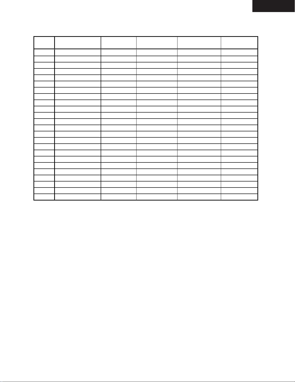
Tab.2 Signal table
No. Signal
1 NTSC 15.734 60 2 PAL 15.625 50 3 PAL60 15.734 60 4 SECAM 15.625 50 5 VESA 640 x 350 37.86 85.08 31.5
6 NEC 640 x 400 24.83 56.43 21.053
7 MAC 640 x 400 35 66 30.24
8 NEC 640 x 400 31.47 70 25.175
9 IBM 640 x 400 31.47 70 25.175
10 VESA 640 x 400 37.86 85.08 31.5
11 VESA 640 x 480 31.47 59.94 25.175
12 IBM 640 x 480 31.47 60 25.175
13 MAC 640 x 480 31.47 60 25.175
14 NEC 640 x 480 31.47 60 25.175
15 MAC 640 x 480 34.97 66.67 31.334
16 MAC 13" 640 x 480 35 66.67 30.24
17 VESA 640 x 480 37.86 72.81 31.5
18 VESA 640 x 480 37.5 75 31.5
19 IBM 640 x 480 39.375 75 31.49
20 VESA 640 x 480 43.269 85.01 36
21 IBM 720 x 350 31.469 70.09 28.322
22 VESA 720 x 400 37.927 85.04 35.5
23 IBM 720 x 350 39.44 87.85 35.5
24 IBM 720 x 400 39.44 87.85 35.5
25 VESA 800 x 600 35.16 56.25 36
26 VESA 800 x 600 37.879 60.32 40
27 VESA 800 x 600 48.077 72.19 50
28 VESA 800 x 600 46.88 75 49.5
29 VESA 800 x 600 53.674 85.06 56.25
30 MAC 16" 832 x 624 49.725 74.55 57.283
31 VESA 1024 x 768 35.5 43 INT 44.9
32 VESA 1024 x 768 48.363 60 65
Resolution
(dots)
H Frequency
(KHz)
V Refresh Rate
(Hz)
DLV-100
Dot Clock
(MHz)
Page 8
DLV-100
No. Signal
33 VESA 1024 x 768 57.476 70.07 75
34 MAC 19" 1024 x 768 60.241 74.93 80
35 VESA 1024 x 768 60.023 75.03 78.75
36 VESA 1024 x 768 68.677 85 94.5
#37 VESA 1152 x 864 67.5 75 108
#38 MAC 21" 1152 x 870 68.681 75.06 100
#39 SUN 1152 x 900 61.796 65.95 92.94
#40 SGI 1152 x 900 71.736 76.05 105.6
#41 VESA 1280 x 960 60 60 108
#42 VESA 1280 x 960 85.94 85 148.5
#43 VESA 1280 x 1024 63.981 60.02 108
#44 MAC(1280EG) 1280 x 1024 69.87 65.18 118.5
#45 NEC(EWS4800) 1280 x 1024 75.12 71.2 125
#46 VESA 1280 x 1024 79.976 75.03 135
#47 VESA 1280 x 1024 91.146 85.02 157.5
#48 VESA 1600 x 1200 75 60.0 162
#49 VESA 1600 x 1200 81.25 65.0 175.5
#50 VESA 1600 x 1200 87.5 70.0 189
#51 VESA 1600 x 1200 93.75 75.0 202.5
#52 HDTV (1080i) 1920 x 1080 33.75 60 Interlace 74.25
#53 HDTV (720p) 1280 x 720 45 60Progressive 74.25
54 SDTV (480p) 720 x 483 31.47 59.94 Progressive 27
55 DVD YCbCr 15.734 59.94 Interlace 56 DVD YCbCr 15.625 50 Interlace -
# Images are compressed by Advanced AccuBlend
Only separate sync is available for UXGA signals.
Resolution
(dots)
H Frequency
(KHz)
V Refresh Rate
(Hz)
Dot Clock
(MHz)
Page 9
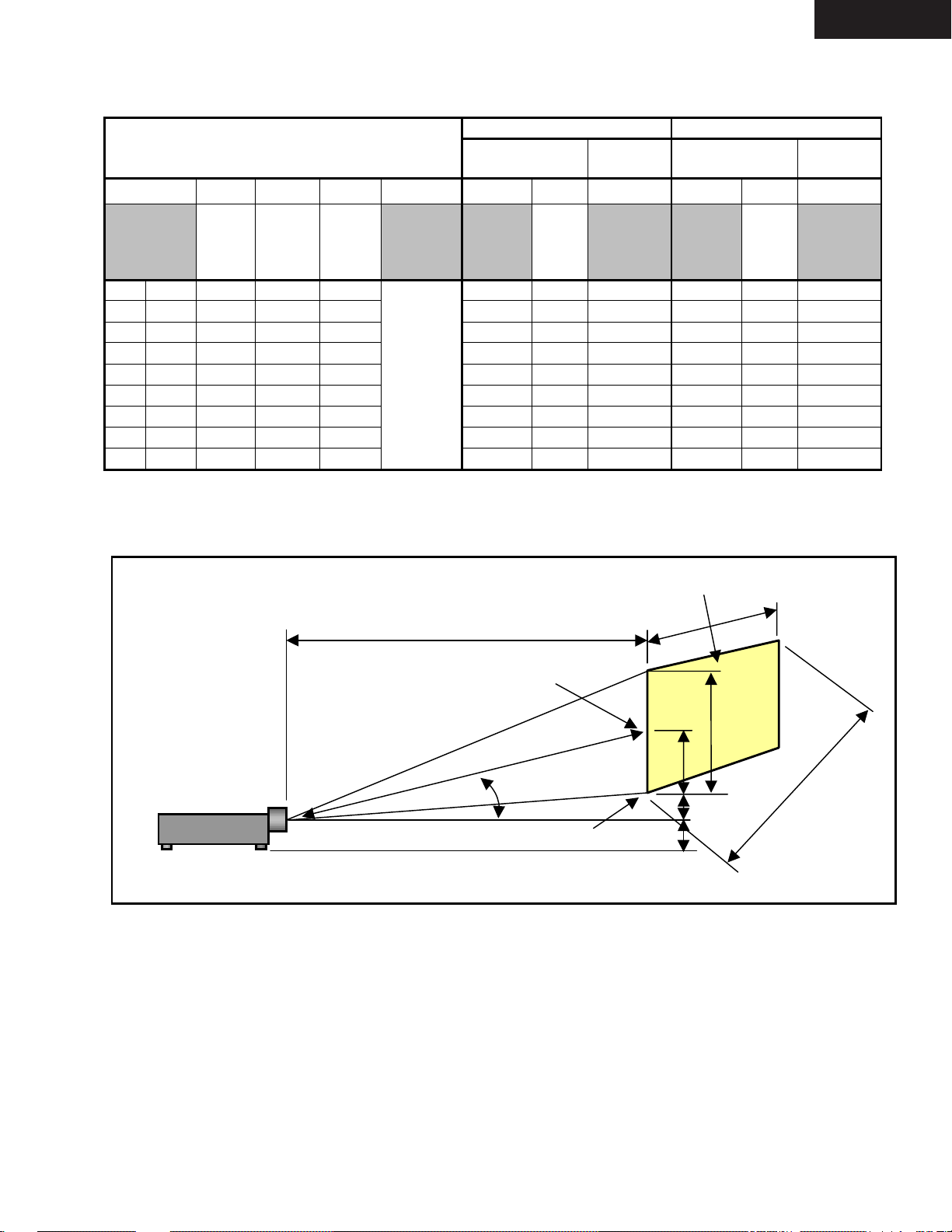
Tab.3 Projection size and throwing angle
C
D
H
Screen Size
a
Diagonal
(inch) (mm)
Projection
Distance
HED g C
Width
(mm)
a/5*4
Height
(mm)
a/5*3
Half
height
(mm)
E/2
Projector
base to
lens center
(mm)
Distance
(mm)
Wide Tele
α
Degree
tan
1
(D+B/
C)
-
Screen
bottom
BC
Height of
Screen
Bottom
(mm)
Projection
Distance
Distance
(mm)
α
Degree
tan
1
(D+B/
C)
-
Screen
bottom
B
Height of
Screen
Bottom
(mm)
30 762 610 457 229 1158 14.7 77 1411 12.2 78
40 1016 813 610 305 1560 14.6 103 1897 12.1 104
60 1524 1219 914 457 2363 14.4 154 2869 12 155
80 2032 1626 1219 610 3167 14.4 206 3841 12 207
100 2540 2032 1524 762 3971 14.3 257 4813 12 259
38
120 3048 2438 1829 914 4775 14.3 309 5785 11.9 311
150 3810 3048 2286 1143 5981 14.3 386 7243 11.9 389
180 4572 3658 2743 1372 7186. 14.3 463 8701 11.9 466
200 5080 4064 3048 1524
7990 14.3 515 9673 11.9 518
( Note )
The value in the table is a design value including +/- 5 % tolerance
DLV-100
Screen center
A
α
Screen bottom
Ground line
Fig.4 Projection figure
Projection Screen
E
a
B
g
Page 10

SAFETY PRECAUTIONS
CAUTION
DLV-100
RISK OF ELECTRIC SHOCK
CAUTION: TO REDUCE THE RISK OF ELECTRIC SHOCK, DO NOT REMOVE
COVER. NO USER-SERVICEABLE PARTS INSIDE. REFER SERVICING
TO QUALIFIED SERVICE PERSONNEL.
This symbol warns the user that uninsulated voltage within the unit may
have sufficient magnitude to cause electric shock. Therefore, it is dangerous
to make any kind of contact with any part inside of this unit.
This symbol alerts the user that important literature concerning the
operation and maintenance of this unit has been included.
Therefore, it should be read carefully in order to avoid any problems.
DO NOT OPEN
ATTENTION
RISQUE D'ELECTROCUTION
NE PAS OUVRIR
MISE EN GARDE: AFIN DE REDUIRE LES RISQUES D' ELECTROCUTION, NE PAS
DEPOSER LE COUVERCLE, IL N'Y A AUCUNE PIECE
UTILISABLE A L'INTERIEUR DE CET APPAREIL. NE CONFIER
LES TRAVAUX D'ENTRETIEN QU'A UN PERSONNEL QUALIFIE.
Ce symbole a pour but de prévenir I' utilisateur de la présence d'
une tension dangereuse, non isolée se trouvant à l' intérieur de l'
appareil. Elle est d' une intensité suffisante pour constituer un risque
d' électrocution. Eviter le contact avec les pièces à l' intérieur de
cet appareil.
Ce symbole a pour but de prévenir l' utilisateur de la présence d'
importantes instructions concernant l' entretien et le fonctionnement
de cet appareil. Par conséquent, elles doivent être lues
attentivement afin d' éviter des problèmes.
Page 11

SAFETY PRECAUTIONS
DLV-100
During servicing carefully observe the following.
1. OBSERVE ALL PRECAUTIONS
Items and locations that require special care during servicing, such as the cabinet, chassis, and parts are labelled
with individual safety instructions. Carefully comply with
these instructions and all precautions in the instruction
manual.
2. BE CAREFUL OF ELECTRIC SHOCK
The chassis carries an AC voltage. If you touch the
chassis while it is still alive, you will get a severe shock.
If you think the chassis is alive, use an isolating
transformer or gloves, or pull out the plug before
replacing any parts.
3. USE SPECIFIED PARTS
The components have been chosen for minimum
flammability and for specific levels of resistance value
and withstand voltage. Replacement parts must match
these original specifications. Parts whose specifications
are particularly vital to safe use and maintenance of the
set are marked on the circuit diagrams and parts list.
Substitution of these parts can be dangerous for you
and the customer, so use only specified parts.
4. REMOUNT ALL PARTS AND RECONNECT ALL
WIRES AS ORIGINALLY INSTALLED
For safety, insulating tape and tubes are used
throughout, but some lift-off parts on the printed wiring
board require special attention.
All wires are positioned away from high-temperature and
high-voltage parts, and, if removed for servicing, they
must be retuned precisely to their original positions.
5. LAMP
Be very careful of the lamp because it generates high
heat while it is used at high voltage. When replacing
the bulb, make sure it is cool enough.
6. LENS
Do not look into the lens during projection. This important
to avoid damage to the eyes.
7. SERVICING
At the time of repair or inspection services, use an earth
band (wrist band), without fail.
8. RUN A COMPLETE SAFETY CHECK AT THE
COMPLETION OF SERVICING
After completion of servicing, confirm that all screws,
parts, and wiring, removed or disconnected for servicing,
have been returned to their original positions. Also
examine if the serviced sections and peripheral areas
have suffered from any deterioration as a result of
servicing. In addition, check insulation between external
metallic parts and blades of wall-outlet plugs. This
examination is indispensable in confirming complete
establishment of safety.
(Insulation check)
Pull out a plug from a wall outlet to disconnect the
connection cable. Then turn on the POWER switch.
Use a 500V megger (Note 2) and confirm that the
insulation resistance is 1MΩ or more between each
terminal of the plug and exposed external metal (Note
1). If the measured value is below the specified level,
then it is necessary to inspect and fix the set.
(Note 1)
Exposed external metal....RGB input terminals, control
terminals, etc.
(Note 2)
If a 500V megger is not available for an unavoidable
reason, then use a circuit tester or the like for inspection.
Page 12
TROUBLESHOOTING
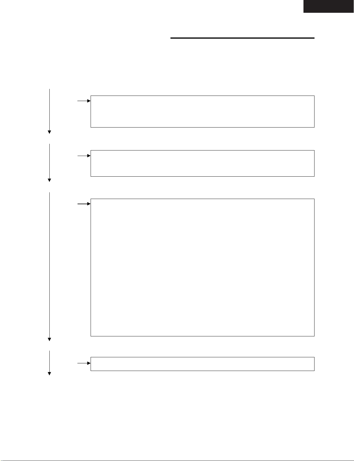
1. Operation check
A certain degree of diagnosis can be carried out by examining the equipment operation in the state of ordinary
usage.
Prior to the removal of the top cover, check the points shown below.
• Is the POWER indicator lit in orange when in standby?
No • The POWER cord is not correctly inserted.
• A connector (POPA, POPB, POSW) is pulled out.
• The POWER unit is defective.
• The MAIN PWB, SUB PWB, or the membrane switch is defective.
Yes
• Is the POWER indicator lit in green when POWER is ON?
No • The lamp’s life has expired. (The STATUS indicator is lit.)
• The connector (POSW) is pulled out.
• The optical engine is defective.
Yes
DLV-100
• Is the STATUS indicator flashing?
Yes • The lamp fails to light. (Flash in a 12-second cycle. ON for 6 seconds and OFF for
6 seconds)
• The lamp is broken. (Flash in a 12-second cycle. ON for 6 seconds and OFF for 6
seconds)
• Connector (PODB or DC) is pulled out. (Flash in a 12-second cycle. ON for 6 seconds and OFF for 6 seconds)
• Connector (POFA or POFB) is pulled out. (Flash in an 8-second cycle. ON for 4
seconds and OFF for 4 seconds)
• The fan stops due to failure or intrusion of foreign substance. (Flash in an 8-second
cycle. ON for 4 seconds and OFF for 4 seconds)
• Deviation from the range of normal operating ambient temperature conditions. (Flash
in a 4-second cycle. ON for 2 seconds and OFF for 2 seconds)
• The connector (POLA) is pulled out. (Flash in a 4-second cycle. ON for 2 seconds
and OFF for 2 seconds)
• The lamp house is dislodged. (Flash in a 1-second cycle. ON for 0.5 seconds and
OFF for 0.5 seconds)
• The connector (POLB) is pulled out. (Flash in a 1-second cycle. ON for 0.5 seconds
and OFF for 0.5 seconds)
• The POWER unit or peripheral circuits of the CPU are defective.
No
• Is the STATUS indicator lit?
Yes • Lamp timer has reached 1000 hours.
No
• CPU’s peripheral circuit malfunction. Breakage of programs and data.
Page 13

TROUBLESHOOTING
2. MAIN PWB, SUB PWB (PWC-4448A)
• Are the following voltage inputs available at POPA (connection between POWER unit and POPA)?
Pin No. Related circuits
1 +12V AUDIO circuit
2 GND GND
3 +5V RGB, VIDEO signal processing system
4 +5V RGB, VIDEO signal processing system
5 GND GND
6 GND GND
7 +5V CPU, FLASHROM, DRAM, G/A
8 +5V CPU, FLASHROM, DRAM, G/A
9 GND GND
10 GND GND
11 —
No → Connections of the POPA connector are defective. The POWER unit is defective.
Yes
DLV-100
• Are the following voltage inputs available at POPB (connection between POWER unit and POPB)?
Pin No. Related circuits
1 +12V Fan and formatter board
2 GND FANGND
3 +3.3V Formatter board
4 +3.3V Formatter board
5 +3.3V Formatter board
6 GND GND
7 GND GND
8 GND GND
No → Connections of the POPB connector are defective. The POWER unit is defective.
Yes
• Are the following signal outputs available at PODA (connection between Optical Engine unit and PODA)?
Pin No.
6, 8, 10, 12, 14, 16, 18 +3.3V
61, 63, 65 +12V
67, 69, 71 +5V
92 Horizontal sync signal (TTL)
31 Vertical sync signal (TTL)
33 Enable signal (TTL)
35 Clock sync signal (TTL)
37, 39, 41, 43, 96, 98, 100, 102 B-ch signal (TTL)
45, 47, 49, 51, 104, 106, 108, 110 R-ch signal (TTL)
53, 55, 57, 59, 114, 116, 118, 120 G-ch signal (TTL)
No → Connections of the PODA connector are defective. The MAIN or SUB PWB is defective.
Yes
• Optical engine unit out of order
• Miscellaneous. Problem in the MAIN and SUB PWBs.
Poor contact in the connector (POMA1–POMA2, POMB1–POMB2) between MAIN PWB and SUB PWB.
Inadequate soldering or cracks in PWB.
Page 14

Getting to Know Your Projector DLV-100
DLV-100
Front/ Side Features
Adjustable Tilt Foot
Zoom Ring
Focus Ring
Lens
Controls
L
E
C
N
A
C
R
E
T
N
E
SELECT
U
N
E
M
AUTO
ADJUST
PC CARD ACCESS
SOURCE
STAND BY
ON/
POWER
STATUS
Ventilation (inlet)
Adjustable Tilt Foot Button
Remote Sensor
Lens Cap
Attaching the lens cap to the lens hood with the supplied string and rivet
1. Thread the string through the hole on the lens cap and then tie a knot in the string.
2. Use the rivet to attach the string to the bottom of the lens hood.
○○○○○○○○○○○○○○○○○○○○○○○○
○○○○○○○○○○○○○○○○○○○○○○○○
Attaching the lens cap
Page 15
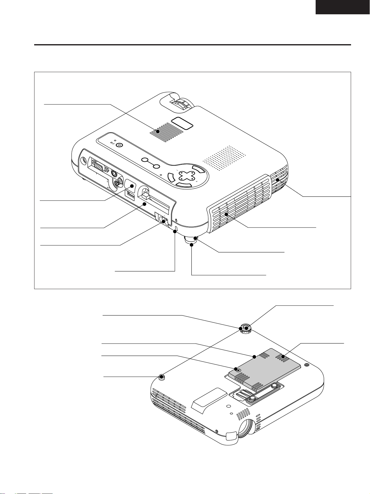
Rear/ Side Features
Monaural Speaker (1W)
POWER
STATUS
ON/
STAND BY
DLV-100
SOURCE
AUDIO
Remote Sensor
Terminals and PC card
AC Input
Bottom
PC CARD ACCESS
RGB
S-VIDEO
PC CONTROL
VIDEO
USB
PC CARD
Slot for Kensington
MicroSaver
Security System
Rear Foot
Rotate to fine-adjust horizontally
position
Lamp cover
AUTO
ADJUST
AC IN
M
E
N
U
SELECT
E
N
T
E
R
C
A
N
C
E
L
Ventilation (inlet)
Ventilation (outlet)
Heated air is exhausted from here
Rear Foot
Spacer (black rubber)
Spacer (black rubber)
To fine-adjust the height of the rear foot, remove
the spacer and rotate the rear foot to the desired
height.
Ventilation (inlet)
Lamp cover screw
Rear Foot
(not adjustable)
NOTE: The projector has an internal temperature sensor. The sensor controls the speed of the fan to keep
constant temperature in the inside.
When the internal temperature rises, the built-in fan automatically runs at a high speed (high-speed mode).
During this time, the sound of exhaust may be heard.
This is not a malfunction.
Page 16

DLV-100
STATUS
2
ON/
STAND BY
Top Features
POWER
3
1
AUDIO
RGB
S-VIDEO
PC CONTROL
VIDEO
USB
1. Power Button (ON / STAND BY)
Use this button to turn the power on and off when the power is
supplied and the projector is in standby mode.
2. Status Indicator
When this is lit red continually, it's warning you that the projection
lamp has exceeded 1500 hours (1000 hours in High-Bright mode)
of service. After this light appears, it is advisable to replace the
projection lamp as soon as possible. (See page 44). In addition the
message "The lamp has reached the end of its usable life. Please
replace the lamp!!." appears continually until the lamp is replaced.
If this light blinks red rapidly, it indicates that the lamp cover is not
attached properly or the projector is overheated.
See the Power/Status Light Messages on page 45 for more details.
3. Power Indicator ( )
When this indicator is green, the projector is on; when the indicator is orange, it is in standby mode.
4. Source Button
Use this button to select a video source such as a PC, VCR, DVD
player or PC Card Viewer (CompactFlash card).
Each time this button is pressed, the input source will change as
follows:
→ RGB → Video → S-Video → PC Card Viewer
If no input signal is present, the input will be skipped.
SOURCE
PC CARD
4
5
10
9
PC CARD ACCESS
AUTO
ADJUST
M
E
N
U
C
A
SELECT
N
C
E
L
E
N
T
E
R
6
7
8
5. Auto Adjust Button (RGB only)
Use this button to adjust Position-H/V and Pixel Clock/Phase for
an optimal picture. Some signals may not be displayed correctly or
take time to switch between sources.
6. PC Card Access Indicator
Lights while accessing a CompactFlash memory card.
7. Enter Button
Executes your menu selection and activates items selected from
the menu.
8. Cancel Button
Press this button to exit "Menus". Press this button to return the
adjustments to the last condition while you are in the adjustment
or setting menu.
9. Select (▲▼ ) / Volume (+) (–) Buttons
▲▼: Use these buttons to select the menu of the item you wish
to adjust.
When no menus appear, these buttons work as a volume
control.
: Use these buttons to change the level of a selected menu
item.
A press of the button executes the selection.
When the menus or the Viewer tool bar is not displayed,
these buttons can be used to select a slide, or to move the
cursor in Folder List or Slide List.
When the magnifying glass is displayed, these ▲▼
buttons move the magnifying glass.
10. Menu Button
Displays the menu.
Page 17

Terminal Panel Features
TU
PO
1
AUDIO
RGB
WER
2
S-VIDEO
PC CONTROL
DLV-100
S
ON/
STAND BY
3
SOURCE
4
PC CARD ACCESS
5
VIDEO
AUTO
ADJUST
6
M
E
N
U
C
A
SELECT
N
C
E
L
E
N
T
E
R
USB
7
8
1. Audio Input Mini Jack (3.5 mm ∅)
This is where you connect audio output from your computer, VCR,
DVD player or laser disc player.
A commercially available audio cable is required.
2.
RGB Input/ Component Input Connector (Mini D-Sub 15 pin)
Connect your PC or other RGB equipment such as IBM or compatible computers. Use the supplied RGB cable to connect to a PC.
Or connect a Macintosh computer here using the supplied RGB
cable. This also serves as a component input connector that allows
you to connect a component video output of component equipment such as a DVD player.
3. S-Video Input (Mini DIN 4 Pin)
Here is where you connect the S-Video input from an external source
like a VCR.
NOTE: S-Video provides more vivid color and higher resolution than the
traditional composite video format.
4. Video Input (RCA)
Connect a VCR, DVD player, laser disc player, or document camera here to project video.
5. PC Card Eject Button
Press to eject a CompactFlash memory card.
6. PC Card Slot
Insert a CompactFlash memory card here.
7. PC Control Port (Mini DIN 8 Pin)
Use this port to connect your PC to control your projector via a
serial cable. This enables you to use your PC and serial communication protocol to control the projector.
PC CARD
AC IN
9
If you are writing your own program, typical PC control codes are
on the back cover page.
A cap is put on the port at the factory. Remove the cap when using
the port.
8. USB Terminal
Connect a commercially available mouse that supports USB. You
can operate the menu or PC Card Viewer with the USB mouse via
this terminal.
Note that this terminal is not used with a computer and that there
may be some brands of USB mouse that the projector does not
support.
9. AC Input
Connect the supplied power cable's three-pin plug here. When you
plug the other end into an active wall outlet, the POWER indicator
turns orange and the projector is in standby mode.
10. Built-in Security Slot (
This security slot supports the MicroSaver® Security System.
MicroSaver® is a registered trademark of Kensington Microware
Inc.
The logo is trademarked and owned by Kensington Microware Inc.
10
)
Page 18

5
6
4
0
DLV-100
Remote Control Features
1. Infrared Transmitter
Direct the remote control toward the remote sensor on the projector cabinet.
2. Standby/On Button
If the main power is applied, you can use this button to turn your
projector on or put it in standby.
3. S-Video Button
Press this button to select an S-Video source from a VCR.
4. Video Button
Press this button to select an NTSC, PAL, SECAM or NTSC4.43
compatible video source from a VCR, DVD player, laser disc player
or document camera.
5. RGB Button
Press this button to select a video source from computer or component equipment connected to your RGB port.
6. Auto Adjust Button
Use this button to adjust an RGB source for an optimal picture.
Some signals may not be displayed correctly or take time to switch
between sources.
Supplied Remote Control
5
6
7
11
12
13
17
INPUT
1
2
3
4
8
9
1
1
1
1
7. Magnify + - Buttons
Use this button to adjust the image size up to 400%.
To change the position of the magnified screen, press one of the
▲▼
8. Volume + - Buttons
Press + button to increase the volume and - button to decrease
it.
9. ASPECT Button
Press this button to select the screen size.
10. Mute Button
This button turns off an image and sound for a short period of time.
Press again to restore the image and sound.
NOTE: When the menu is displayed, a press of this button mutes an image
and sound without turning off the menu.
11. PICTURE Button
Press this button to recall and display the screen-related menu.
12. Freeze Button
This button will freeze a picture. Press again to resume motion.
13. Menu Button
Displays the menu for various settings and adjustments.
14. LAMP RESET Button
If the lamp has been turned on for more than 1,600 hours (Normal
mode), the power to the unit will be cut off and no messages will
be displayed. Press and hold down this button for 10 seconds or
more while the unit is in stand-by mode to clear the lamp available
time and the lamp usage time.
buttons to recall the magnifying glass, then use the ▲▼
buttons to move the screen.
15. ▲▼
▲,▼: Use these buttons to select the menu of the item you wish
16. Cancel Button
Press this button to exit "Menus". Press this button to return to the
previous menu without storing the current settings or adjustments
when you are in the submenu or adjustment screen.
17. Enter Button
Press this button to execute the selected item. When this is pressed,
the adjustments and settings are saved, and the display is returned
to the menu.
(Select) Buttons
to adjust.
, : Use these buttons to change the level of a selected menu
item.
A press of the button executes the selection.
When the magnifying glass is displayed, these ▲▼
buttons move the magnifying glass.
Page 19

DISASSEMBLY
• In regard to the part name and the part number of each symbol,
DLV-100
M08
E02
M01
M07
M03
S05
S07
M13
M14
E04
S05
S05
E06
M22
M11
M21
S05
E05
S05
M19
M11
M20
S05
M12
A02
E11
E10
S05
S05
S01
E08
S13
S08
S08
M17
S14
M23
S12
S08
S08
M16
M46
S11
M18
S08
E07
E09
please refer to the parts table.
S15
S05
S10
M15
E12
S16
S09
S08
M04
S16
M28
M29
M30
M34
E14
M33
A03
E13
S05
M10
S05
M32
S17
M36
S18
M05
M06
S06
S02
A01
M09
S03
S04
M27
E01
M26
S01
M26
M25
S01
M24
S01
M26
S08
E03
M47
M31
S05
M37
M48
S05
M45
M38
S05
M43
S05
M42
S05
M35
M40
M44
M39
M41
Page 20

DLV-100
BLOCK DIAGRAMS
Page 21

DLV-100
Page 22

DLV-100
Page 23

DLV-100
Page 24

DLV-100
Page 25

DLV-100
Page 26

DLV-100
Page 27

DLV-100
Page 28

DLV-100
Page 29

DLV-100
Page 30

DLV-100
CONNECTION DIAGRAMS
Page 31

REPLACEMENT PART LIST
DLV-100
C-No Description Part number
PWB ASSYS
E08 MAIN PWB ASSY 81E94FA1
E07 SUB PWB ASSY 81E94FB1
E03 REM PWB ASSY 81E94FC1
ELECTRICAL PARTS & MISCELLANOUS PARTS
4 POWER SUPPLY(BALLAST) 3N100131
5 POWER SUPPLY(DC) 3N100002
E05 FAN (LAMP) 3N170021
E06 FAN (PSU) 3N170022
SW5501 POWER SWITCH LM3525MX-H 3N7J0001
SPEAKER 20*35MM 8H 1W 6N300004
CN3P(RM)105W,1685-26 7NW3W005
CN8P(PB)175W,1685-26 7NW8W001
CN11P(PA)65W,1685-26 7NWAW001
M37 ZOOM LENS(01 DLP) 12JS2691
M24 BOTTOM COVER BK ASSY 24PS2901
COVER(LENS Z) 24F35271
M47 FILTER(F) 24F32641
CAP(PC CONTROL) 24F32691
M03 PANEL(FAN B) 24F34621
M09 HOLDER(BALLAST B) 24F34641
21 HOLDER(FAN 20) 24F34651
M48 LENS CAP ZK 24F35641
TERMINAL PANEL B ASSY 24FT8071
FILTER(B) 24F32651
M04 TERMINAL PANEL B 24F35331
COVER(VIEWER B) 24F35341
SPRING(VIEWER) 24H35091
BRACKET(I/O) 24H37602
BRACKET(I/O) 24H37611
BRACKET(TOP) 24H39781
M15 PLATE(I/O B) 24H41781
M16 SHEET,INSULATOR(TOP) 24J16122
M17 SHEET,INSULATOR(CPU-PWB) 24J16133
M46 SHEET,INSULATOR(POWER) 24J16143
SPACER(7*7*3.5) 24J16401
SPACER(210*10*5) 24J16411
SPACER(70*10*5) 24J16421
SPACER(50*10*5) 24J16431
SPACER(REAR FOOT) 24J16451
SHEET(LENS CAP Z) 24J18241
41 CUSHION(T1*5*28) 24J19401
CAUTION LABEL(SERVICE U) 24L45241
CAUTION LABEL(SERVICE J) 24L45251
NAME PLATE 24L47221
CAUTION LABEL(LENS K) 24L47231
CAUTION LABEL(HOT K) 24L47241
CAUTION LABEL(ELEC SHOCK K) 24L47251
M01 TOP COVER ASSY K(XGA-Z) 24PS2891
BUTTON(TILT FOOT A) 24G07911
BRACKET(TOP) 24H37401
SPRING(TILT BUTTON) 24H37421
CUSHION(T8*7*4) 24J19391
SW PANEL(PA14) 7N900221
54 LABEL(1*10) 25765841
S09 SCREW(D-SUB) 24N03112
56 CBIPS*2.6*6*15BF 24N04011
S11 STAD(M2.5,H23.7,M/FM) 24N04861
S13 STAD(M2.5,H13,FM/FM) 24N04871
S01 SPECIAL SCREW(M2.5*6*3KF) 24N04881
S12 SPECIAL SCREW(P2*6*15BF) 24N04891
PUSH NUT(1.5) 24N04901
S08 SPECIAL SCREW(2.5*4*3GF) 24N04911
SPECIAL SCREW(2.5*4*3GF) 24N04921
SPECIAL SCREW(4*4*3KF) 24N04931
SCREW,SL-CPIMS*2*6*15BF 910D2031
NUT,AHEXIN*2*15BF 91430201
M11 FAN RUBBER 79T08867
M14 FAN GUARD 79T08870
C-No Description Part number
A02 LAMP HOUSE ASSY
(M20+M19+M22+M21+M23) 79T09114
E11 THERMISTOR ASSY 79T08873
M10 LENS BASE POLYURETHANE FOAM 79T08877
E10 LIMIT SW BOARD ASSY 79T08878
M18 BRACKET"(I/O) 79T08879
M07 BALLAST LOCK BASE 79T08880
M08 INSULATE SHEET L/D-N 79T08881
E04 BALLAST CONNECTOR 79T08884
M26 REAR FOOT RUBBER 79T08886
M27 REAR FOOT 79T08887
M25 FRONT FOOT 79T08888
A01 LAMP COVER ASSY
(M05+M06+S03+S04) 79T09113
S02 POLYSLIDER CUT W 79T08930
S15 WHEEL SCREW 79T08893
E12 WHEEL SENSOR BOARD ASSY 79T08894
M28 WHEEL COVER 79T08895
M29 COLOR WHEEL UNIT 79T09112
M30 RUBBER SHEET 79T08896
M32 FORMATTER BRACKET 79T08933
A03 DMD SET(XGA)
(E13+M33+M34+E14) 79T09115
M33 ELASTOMER HOLDER 79T08900
M34 ELASTOMER 79T08901
1M35 HEAT SINK A 79T08934
1M36 HEAT SINK B 79T08935
1M39 LENS BASE ASSY
(M31+M40+M41+M42) 79T09111
M43 LENS BASE COVER 79T08906
M44 APERTURE 79T08907
M45 INSULATE SHEET LB-U 79T08908
S18 SCREW No.6-12 79T08918
S14 SCREW φ2.6-5 79T08922
S07 SCREW φ3-6 79T08923
S06 SCREW M3-6 79T08924
PRINTED & PACKING MATERIALS
BAND (L=100) 24280701
SOFT CASE(DLV-100) 24BS6971
SPACER 24M16321
PROTECTION BOX(300*460) 24M16531
CARTON BOX 24MU6831
BATTERY LR6GRSP2A 6N800005
POWER CODE UC3 L3.0 M K 7N080201
RC-473E 7N900271
STRAP 24C05051
PUSH RIVET 24C04531
CABLE,RGB 7N520001
Page 32

METHOD OF DISASSEMBLY
2. TOP COVER ASSY
(1) Remove the five screws 1, and take out the TOP
COVER ASSY.
Note) This action must be taken carefully because the
FFC of SW PANEL and SPEAKER CABLE is
connected to the MAIN PWB ASSY.
TOP COVER ASSY
DLV-100
SW PANEL
1
1
1
1
Page 33

3. PANEL (FAN)/TERMINAL PANEL/FILTER (F)
(1) Take out the PANEL (FAN) and the TERMINAL
PANEL, FILTER (F).
PANEL (FAN)
DLV-100
METHOD OF DISASSEMBLY
TERMINAL PANEL
FILTER (F)
Page 34

3. PANEL (FAN)/TERMINAL PANEL/FILTER (F)
(1) Take out the PANEL (FAN) and the TERMINAL
PANEL, FILTER (F).
PANEL (FAN)
DLV-100
METHOD OF DISASSEMBLY
TERMINAL PANEL
FILTER (F)
Page 35

METHOD OF DISASSEMBLY
4. REPAIR LAMP/LAMP COVER/LAMP COVER GUARD
(1) Loosen the one screw 1 and remove the LAMP
COVER. Then take out the LAMP COVER GUARD
and REPAIR LAMP successively.
DLV-100
REPAIR LAMP
LAMP COVER GUARD
LAMP COVER
POLYSLIDER CUT W
LAMP COVER SCREW SP
1
Page 36

DLV-100
METHOD OF DISASSEMBLY
5. LAMP DRIVER/BALLAST HOLDER N/BALLAST LOCK BASE/BALLAST CONNECTOR/
INSULATE SHEET L/D-N/REM PWB ASSY
(1) Remove the one screw 1, and disconnect the
CONNECTOR of the LAMP DRIVER.
(2) Remove the one screw 2 and another screw 4,
and take out the LAMP DRIVER.
(3) Remove the one screw 5 and take out the REM
PWB ASSY.
BALLAST LOCK BASE
INSULATE SHEET
L/D-N
4
1
LAMP DRIVER
CONNECTOR
3
BALLAST HOLDER N
LAMP DRIVER
2
BALLAST CONNECTOR
5
REM PWB ASSY
Page 37

METHOD OF DISASSEMBLY
6. OPTICAL ENGINE ASSY
(1) Remove the four screws 1, and take out the OP-
TICAL ENGINE ASSY.
DLV-100
1
LENS BASE POLYURETHANE FOAM
1
OPTICAL ENGINE ASSY
Page 38

7. 40 FAN ASSY (L-F)/40 FAN ASSY (DC)/FAN BASE
(1) Remove the two screws 1, and take out the FAN
BASE.
(2) Remove the 40 FAN ASSYs (L-F) and the 40 FAN
ASSYs (DC).
40 FAN ASSY (L-F)
DLV-100
METHOD OF DISASSEMBLY
FAN CUSHION
FAN GUARD
40 FAN ASSY (DC)
FAN RUBBER
FAN RUBBER
1
1
FAN BASE
Page 39

METHOD OF DISASSEMBLY
8. MAIN PWB ASSY/SUB PWB ASSY/POWER SUPPLY/LIMIT SW BOARD ASSY/
SHEET INSULATOR/PLATE (I/O)
(1) Remove the one screw 1.
(2) Remove the one screw 2and one screw 7, and
take out the SHEET INSULATOR.
(3) Remove the three screws 3, and take out the
MAIN PWB ASSY and the SUB PWB ASSY.
2
SHEET INSULATOR
(4) Remove the two screws 4, and take out the PLATE
(I/O).
(5) Remove the one screw 5 and the three STAD 1,
and take out the POWER SUPPLY.
(6) Remove the one screw 6, and take out the LIMIT
SW BOARD ASSY.
7
DLV-100
SPACER
SHEET INSULATOR
6
LIMIT SW BOARD ASSY
MAIN PWB ASSY
2
STAD
3
1
STAD
5
SPACER
3
7
1
STAD
POWER SUPPLY
INSULATING SHEET (D-SUB)
SUB PWB ASSY
4
1
PLATE (I/O)
BRACKET (I/O)
SHEET, INSULATOR
Page 40

METHOD OF DISASSEMBLY
9. LAMP HOUSE/THERMISTOR ASSY/FRONT FOOT/REAR FOOT
(1) Remove the one screw 2, and take out the THER-
MISTOR ASSY.
(2) Remove the three screws 1, and take out the
LAMP HOUSE.
LAMP HOUSE GUARD
1
LAMP HOUSE
THERMISTOR ASSY
DLV-100
1
LAMP HOUSE
MESH TEPE
REAR FOOT
LAMP HOUSE
MESH
LAMP HOUSE
MESH
TEPE
BOTTOM COVER ASSY
2
1
LAMP HOUSE
GUARD F
REAR FOOT RUBBER
REAR FOOT RUBBER
FRONT FOOT
REAR FOOT RUBBER
Page 41

METHOD OF DISASSEMBLY
10. OPTICAL ENGINE ASSY
(1) Remove the one screw 1 and the two screws 2,
and take out the WHEEL SENSOR BOARD ASSY
and WHEEL COVER.
(2) Remove the one screw 3, and take out the
COLOR WHEEL and RUBBER SHEET.
(3) Remove the three screws 4 and take out the
LIGHT TUNNEL ASSY.
(4) Remove the three screws 5 and take out the LENS
UNIT.
(5) Remove the one screw 6 and take out the MIR-
ROR ASSY.
WHEEL SENSOR BOARD ASSY
(6) Remove the one screw 7 and take out the APER-
TURE/LENS BASE COVER.
(7) Remove the one screw 8 and take out the CYL-
INDER MIRROR ASSY.
(8) Remove the two screws 9, and take out the HEAT
SINK A and HEAT SINK B.
0
(9) Remove the four screws
1
, and take out the
FORMATTER BOARD, FORMATTER BRACKET,
ELASTOMER HOLDER, ELASTOMER, and DMD.
DLV-100
1
2
4
LIGHT TUNNEL
ASSY
4
INSULATE
SHEET
LB-U
5
LENS UNIT
POINT RING COVER
2
5
WHEEL COVER
COLOR WHEEL
3
MIRROR
ASSY
6
RUBBER SHEET
ELASTOMER
HOLDER
ELASTOMER
LENS BASE
COVER
8
DMD
LENS
BASE
CYLINDER
MIRROR ASSY
FORMATTER BOARD
FORMATTER BRACKET
APERTURE
7
HEAT SINK B
10
9
HEAT SINK A
Page 42

HD15RCA5
HD15 pin to RCA Cabl
Shipped Separetly
e
Page 43

DLV-100
Integra Division of
ONKYO U.S.A. CORPORATION
18 Park Way, Upper Saddle River, N.J. 07458, U.S.A.
Tel: 201-785-2600 Fax: 201-785-2650 http://www.integrahometheater.com
Integra Division of
ONKYO CORPORATION
Sales & Product Planning Div. : 2-1, Nisshin-cho, Neyagawa-shi, OSAKA 572-8540, JAPAN
Tel: 072-831-8111 Fax: 072-833-5222
Page 44

METHOD OF ADJUSTMENTS
PC Control Software :
The completely adjusted servicing PWB ASSY are in stock.
Therefore, it is unnecessary to use the adjusting software.
For this model, adjustments are carried out only for the opticaln system.
DLV-100
Page 45

METHOD OF ADJUSTMENTS
Control of Optical System
The description below covers the control program for the color wheel sensor of the optical engine unit.
1. Preliminary arrangements for adjustment
i Appropriate spanner (across 5.0mm) Part No. : 9N000002
i Signal generator (with signals of all white, all black, all red, all green, all blue)
i Card remote control (set accessory)
2. Preliminary work for adjustment
i Remove the top cabinet. Remove the membrane switch and the speaker cables from the main unit.
i Actuate the set while a signal input is fed from the signal generator.
* Caution points during work (white area)
DLV-100
Page 46

METHOD OF ADJUSTMENTS
3. Adjustment steps
1. Check the color wheel sensor position.
DLV-100
2. Loosen the sensor lock nut. (About 1/4 turns counterclockwise)
Page 47

METHOD OF ADJUSTMENTS
3. Adjust the sensor by means of tweezers, using only a green image and viewing the screen.
DLV-100
4. Tighten the nut to its original position. (About 1/4 turns clockwise)
(Note: Never tighten it too much.)
Page 48

METHOD OF ADJUSTMENTS
5. When the nut has been completely tightened, check each screen of all white, all red, all blue, all green, and
all black in order to confirm the freedom from any abnormality (chromaticity).
If any abnormality is perceived, adjust the sensor again (in the state of that screen) and check the resultant
conditions again.
6. Apply a screw lock agent to the area of the sensor and the nut.
DLV-100
Note) At the time of adjustments and operation check under the condition that the top cover is open, use a
small-sized cooling fan or the like to avoid excessive temperature rise inside the set.
(The effect of cooling will be lowered if the top cover is removed. In case when the thermal protector
should operate as a result of temperature rise inside the set, pull out the power cord and wait until the
inside is cooled down. Restart is possible after confirming that the inside temperature has been sufficiently low.)
 Loading...