

Page 1
S P E C T R O P H O T O M E T E R
UV-20
USER’S MANUAL
P/N: 435103
REV. 1.0.0
Page 2

Page 3

I
Contents
Safety ............................................................. 1
Package Contents ................................................... 1
Unpacking .......................................................... 1
Installation ....................................................... 2
1. Environment Required .................................................................................................. 2
2. Install Spectrophotometer ...................................................................................... 2
Overview ........................................................... 2
Symbols ............................................................ 3
Main Specifications ................................................ 3
Description of Appearance and Keys ................................. 4
1. Appearance ......................................................................................................................... 4
2. Keypad ................................................................................................................................... 5
3. Description of Keys .................................................................................................... 5
Functions .......................................................... 6
Getting Started .................................................... 6
Important Guidelines ............................................... 7
General Operating .................................................. 7
Measuring .......................................................... 8
1. Photometry ......................................................................................................................... 8
2. Quantitation ..................................................................................................................... 9
3. Utility............................................................................................................................... 13
Troubleshooting ................................................... 15
Repair and Maintenance ............................................ 16
1. Daily Maintain .............................................................................................................. 16
2. Spare Parts Replacement ........................................................................................ 16
Page 4

II
Warranty .......................................................... 20
Equipment Disposal ................................................ 21
Page 5
1
Safety
Please follow the guidelines below, and read this manual in its entirety
to ensure safe operation of the unit.
We recommends against the use of UV-20 Spectrophotometer.
Do not open the device.
Disconnect the device from the mains supply before
carrying out maintenance work or changing the fuses.
The inside of the device is a high-voltage area Danger!
Do not use the device if it is damaged, especially if the
main power cable is in any way damaged or defective.
Repairs may only be carried out by the service technicians
from us and authorized contractual partners.
The device must be connected to a power outlet that has
a protective ground connection.
If the equipment is used in a manner not specified by the
manufacturer, the protection provided by the equipment
may be impaired.
Do not allow any liquid to enter into the device.
Do not operate the device in a hazardous location or
potentially explosive environment.
Package Contents
Description
Quantity
Spectrophotometer
1PC
10mm Glass Cuvette
4PCS
10mm Quartz Cuvette
2PCS
Power Cord
1PC
User’s Manual
1PC
Dust Cover
1PC
Unpacking
Open the package, according to carefully check the packaging packing list
items, if found inside the packaging are missing or damaged items please
Page 6

2
contact us and authorized contractual partners.
Installation
1. Environment Required
To ensure the best performance, the following conditions are required:
The best working temperature range is 16—35℃ and the humidity
is 45—80%.
Keep it as far as possible away from the strong magnetic or
electrical fields or any electrical device that may generate
high-frequency fields.
Set the unit up in an area that is free of dust, corrosive gases
and strong vibrations.
Remove any obstructions or materials that could hinder the flow
of air under and around the instrument.
The power requirement is 110±11V/60±1Hz or 220±22V/50±1Hz.
Use the appropriate power cord and plug into a grounded outlet.
If the local voltage is not stable, a voltage regulator is required.
Be away from direct sunlight.
2. Install Spectrophotometer
Placement
Place the instrument on the stable table carefully.
Install Printer (Printer is Optional Accessories)
Check to confirm instrument power switch is turned off, connect the
printer’s data cable to the instrument’s parallel port.
Link the Power Cord
Check to confirm instrument power switch is turned off, the power cord
plug into two separate power interface and power supply socket apparatus.
Overview
UV-20 Spectrophotometer is an electrical measure instrument which is
widely used in the laboratories.
Use Frequency: Intermittence
Excessive Voltage(Current): No
Pollution Class: Class 1
Page 7
3
Symbols
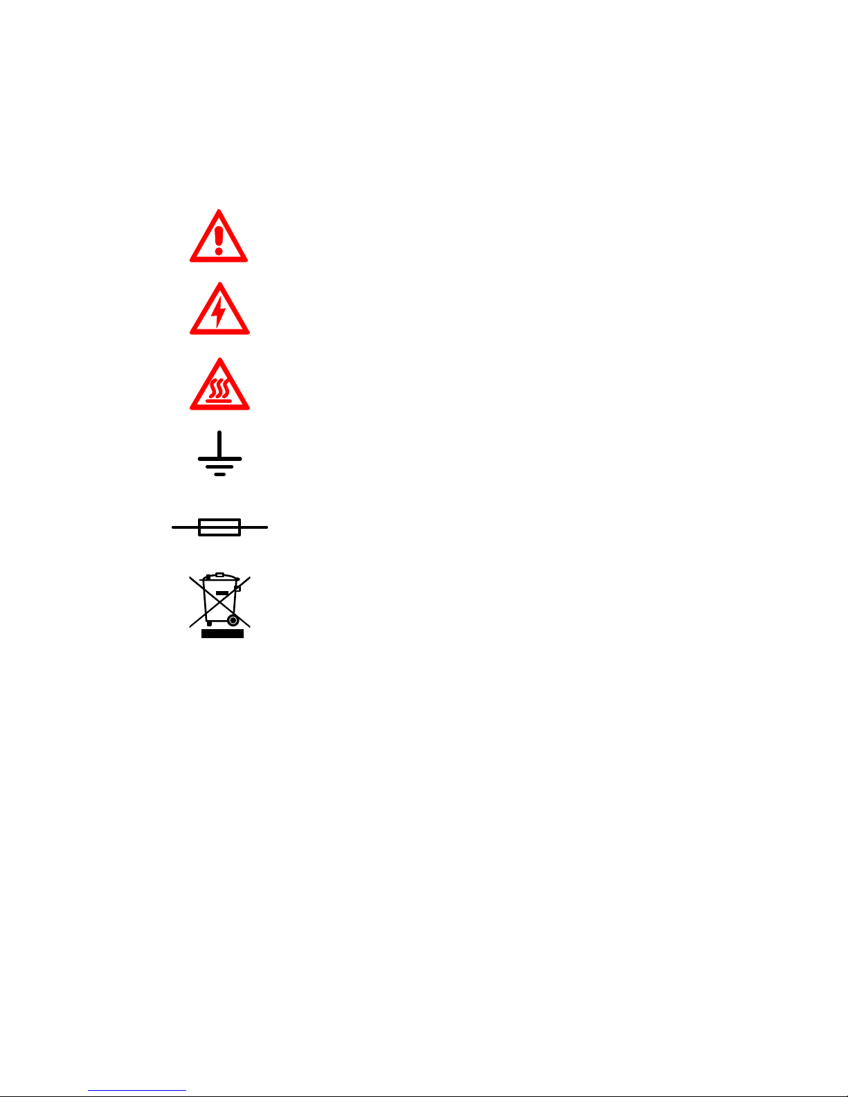
The following chart is an illustrated glossary of the symbols that are
used in this manual.
Caution, Danger!
Caution, High Voltage!
Caution, Hot!
Ground
Fuse
Recycle, this instrument will be called back by the
appointed Electrical Treatment Department or by the
original Manufacturer when wasted.
Main Specifications
Optical System Single beam
Wavelength Range 200—1000nm
Wavelength Accuracy ±2nm
Wavelength Repeatability 0.8nm
Photometric Range -0.3—3A, 0—200%T
Photometric Accuracy ±0.5%T
Photometric Repeatability 0.3%T
Spectral Bandwidth 4nm
Stray Light 0.3%T@220nm&360nm
Stability ±0.002A/h@500nm
Work Mode Photometry, Quantitation
Interface USB, Parallel(printer)
Power Requirement AC 110/220V, 50/60Hz
Page 8
4
Dimensions 490x360x210
Weight 14kg
Work Environment 15—35℃, 15—70% relative humidity
Store Environment -10—50℃, 15—70% relative humidity
Description of Appearance and Keys
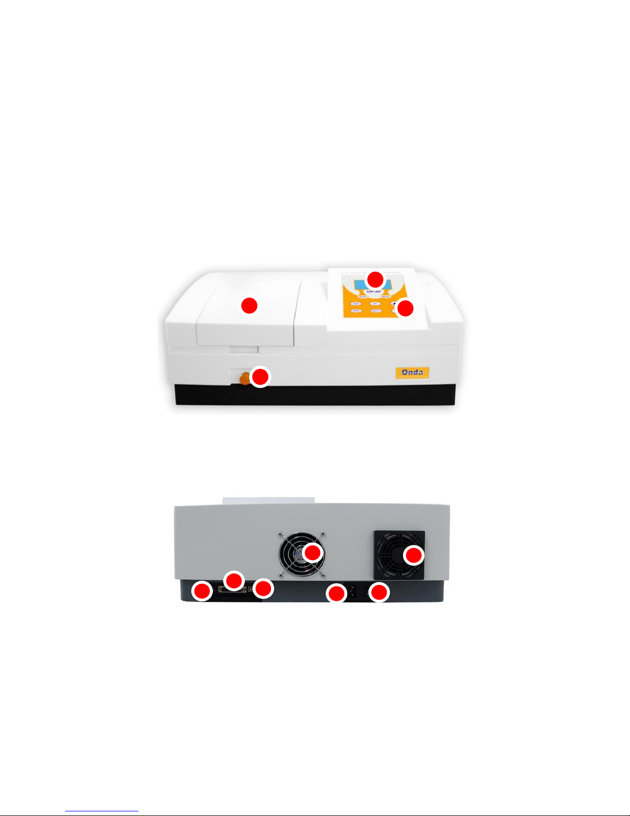
1. Appearance
Front View
1
2
3
4
Back View
5
10
9
8
7
6
11
1 LCD Display
2 Keypad
3 Lid of Sample Room
4 Rod
5 LCD Contrast Adjust
6 Printer port
7 USB port
8 Cover of Fan
9 Power Socket
10 Power Switch
11 Cover of Cooling Vents
Page 9
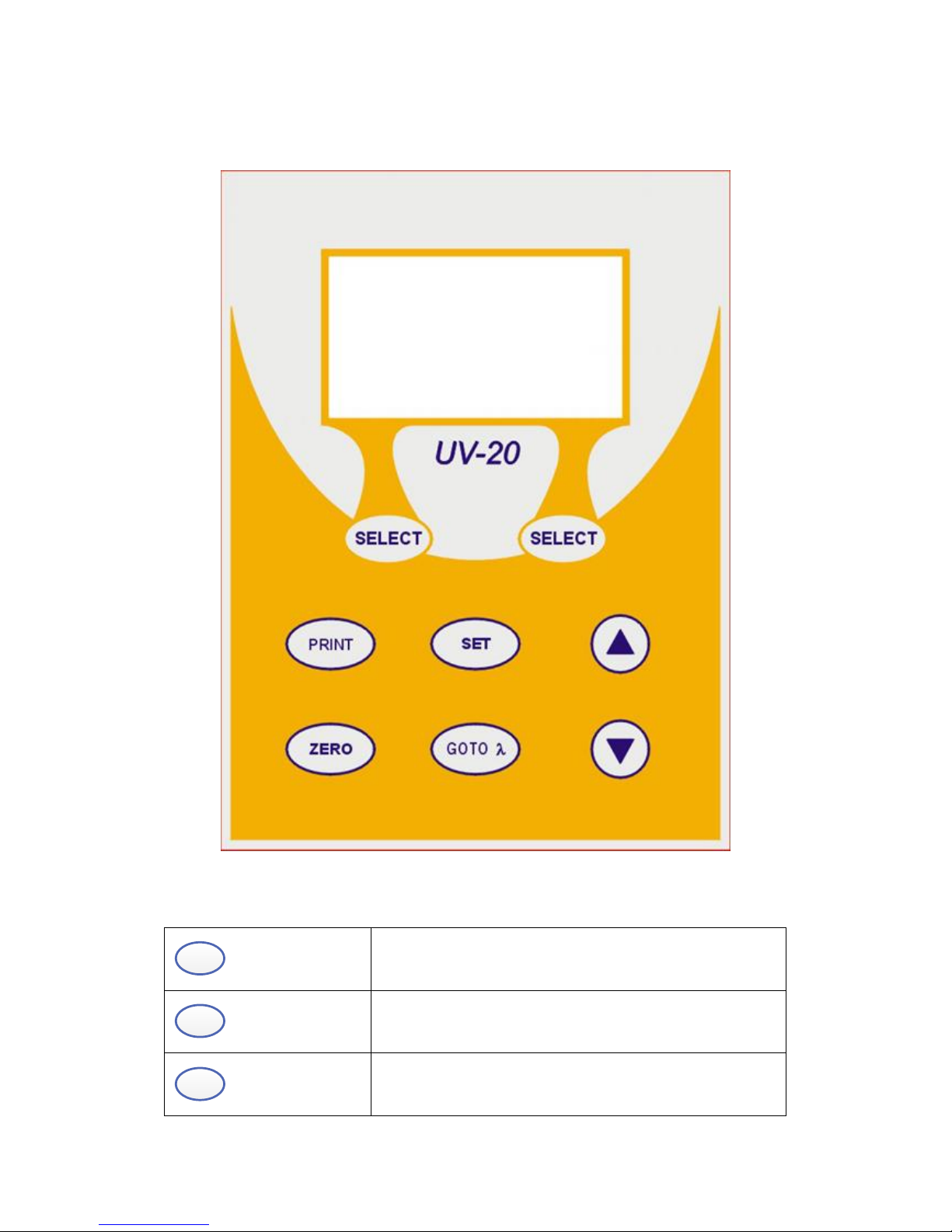
5
2. Keypad
3. Description of Keys
SET
SET Key: Set Parameters
GOTO λ
GOTO ʎ Key: Set Wavelength
ZERO
ZERO Key: Blank
Page 10
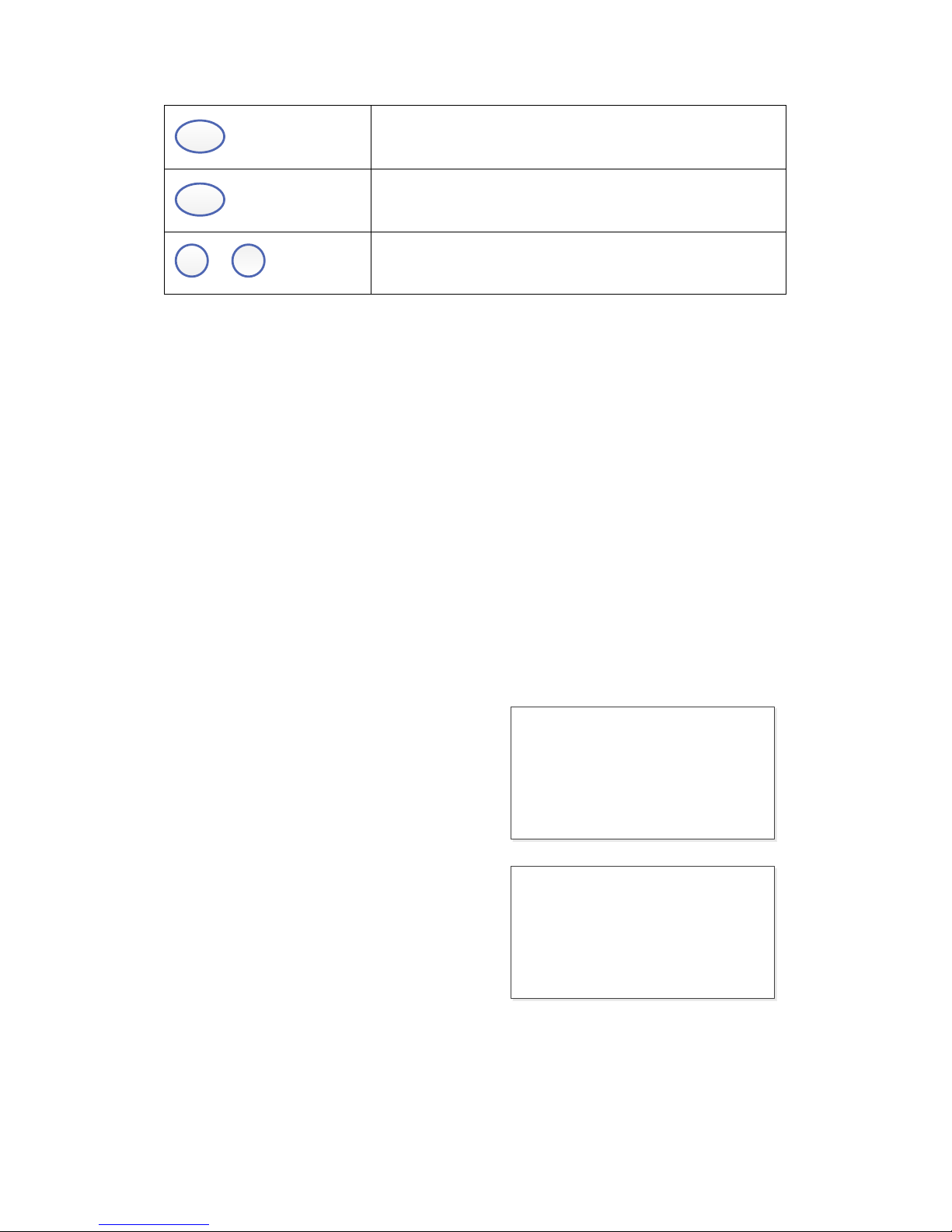
6
PRINT
PRINT Key: Print measuring result
SELECT
Function Key: Functions according to the screen
▲
,
▲
UP, DOWN Keys: Scroll menu/data and set Y scale
Functions
Photometry
Display results as Abs, %T or Energy.
Quantitation
Use a Standard Sample to establish Standard Curve.
Getting Started
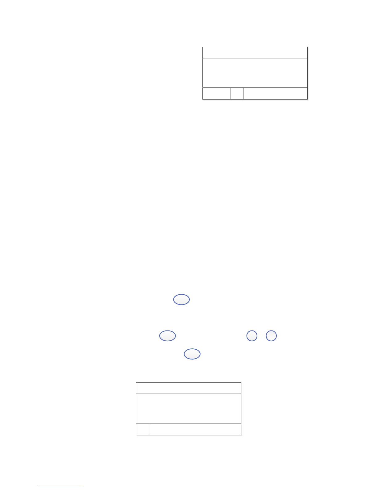
The following chart describes the basic operation of the instrument.
Turn On and Self-check
Switch on the power. Then the
instrument begins to self-check and 20
minutes’ warm up. Self-check includes
the following steps: Turn on lamps →
Check Sensor → Initialize AD → System
position → Get Dark Current → Warm up.
Sel f - t est . . .
War m up 20 mi nut es,
Any key t o ski p
Page 11
7
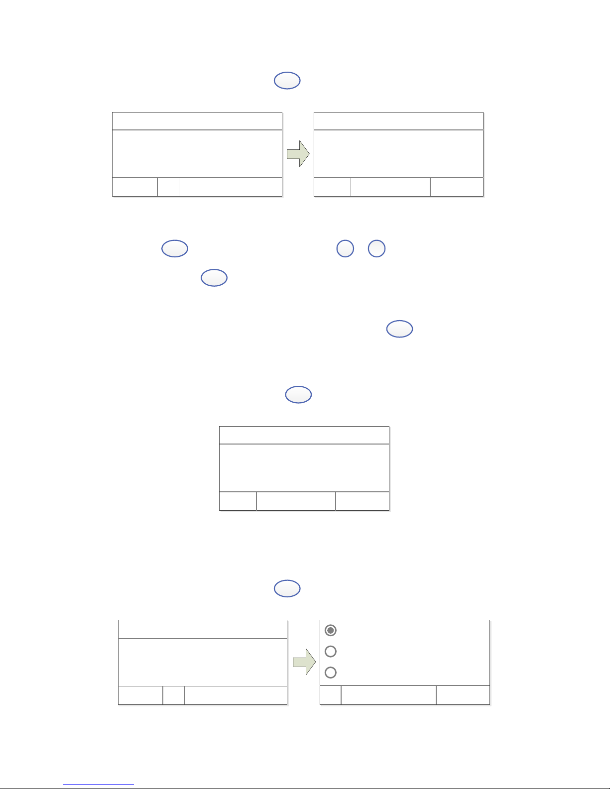
After warm up, instrument displays Main
Interface.
WL: 500. 0nm 0. 000A
100. 0%T
Basi c Quant i t at i ve
Important Guidelines
Reagents and dilution buffers can cause cauterization and other damage
to health.
Samples (nucleic acids, proteins, bacteria cultures) can be infectious
and cause serious damage to health.
During sample preparation, measuring procedures and maintenance and
cleaning work, observe all local laboratory safety precautions (e.g.
wear protective clothing and gloves, use of disinfectant) regarding
the handling of sample material.
Dispose of measuring solutions and cleaning and disinfectant materials
in accordance with the relevant local laboratory regulations.
General Operating
Select Application
Main interface, press the key
SELECT
(left) to enter into.
Set Wavelength
Test interface, press key
GOTO λ
to set wavelength,
▲
,
▲
to modify
wavelength value, then press key
SELECT
(left) to go to wavelength and
blank.
WL: 500. 0nm
Pl ease ent er WL. :
500. 0 nm
OK
Page 12

8
Set Parameters
Press
SET
enter into setup interface,
▲
,
▲
to select items or
input parameters,
SELECT
(left) to confirm.
Delete the test result and stored data
Test Interface, press the key
PRINT
, then press key
▲
,
▲
to select
“Clear Data, not Print ”,
SELECT
(left) to delete.
Blank
Put the Reference in the light path, press
ZERO
to do blank.
Measure Samples
Put the samples in the light path, press
SELECT
(left) to measure.
Print the test results
Test Interface, press the key
PRINT
,
▲
,
▲
select “Print, clear data”,
press the key
SELECT
(left) to print.
Store the Standard Curve
After got the Standard Curve by Marked, press
▲
,
▲
input the file
name and press
SELECT
(left) to save.
Load the Standard Curve
“Quantitative” interface, press
▲
,
▲
to select “Load Curve”, press
▲
,
▲
to choose the curve you want, press
SELECT
(left) to open.
Measuring
1. Photometry
Step 1. Start Photometry
Page 13
9
Main Interface, press key
SELECT
(left) to choose “Basic”.
WL: 500. 0nm 0. 000A
100. 0%T
Basi c Quant i t at i ve
WL: 500. 0nm 0. 000A
No. WL %T Abs.
Test Cancel
Step 2. Set Wavelength
Press
GOTO λ
to set wavelength, press
▲
,
▲
to input wavelength
value, press
SELECT
(left) to go to wavelength.
Step 3. Blank
Put the Reference in the light path and press
ZERO
to do blank.
Step 4. Measure samples
Put the sample in the light path, and then the result displays on the
screen automatically, press
SELECT
(left) to record.
WL: 500. 0nm 0. 000A
No. WL %T Abs.
1 500. 0 100. 0 0. 000
2 500. 0 100. 0 0. 000
Test Cancel
2. Quantitation
Step 1. Start Quantitation
Main Interface, press key
SELECT
(left) to choose “Quantitative”.
Cr eat e Cur ve
Load Cur ve
Cl ear Cur ve
OK Cancel
WL: 500. 0nm 0. 000A
100. 0%T
Basi c Quant i t at i ve
Page 14
10
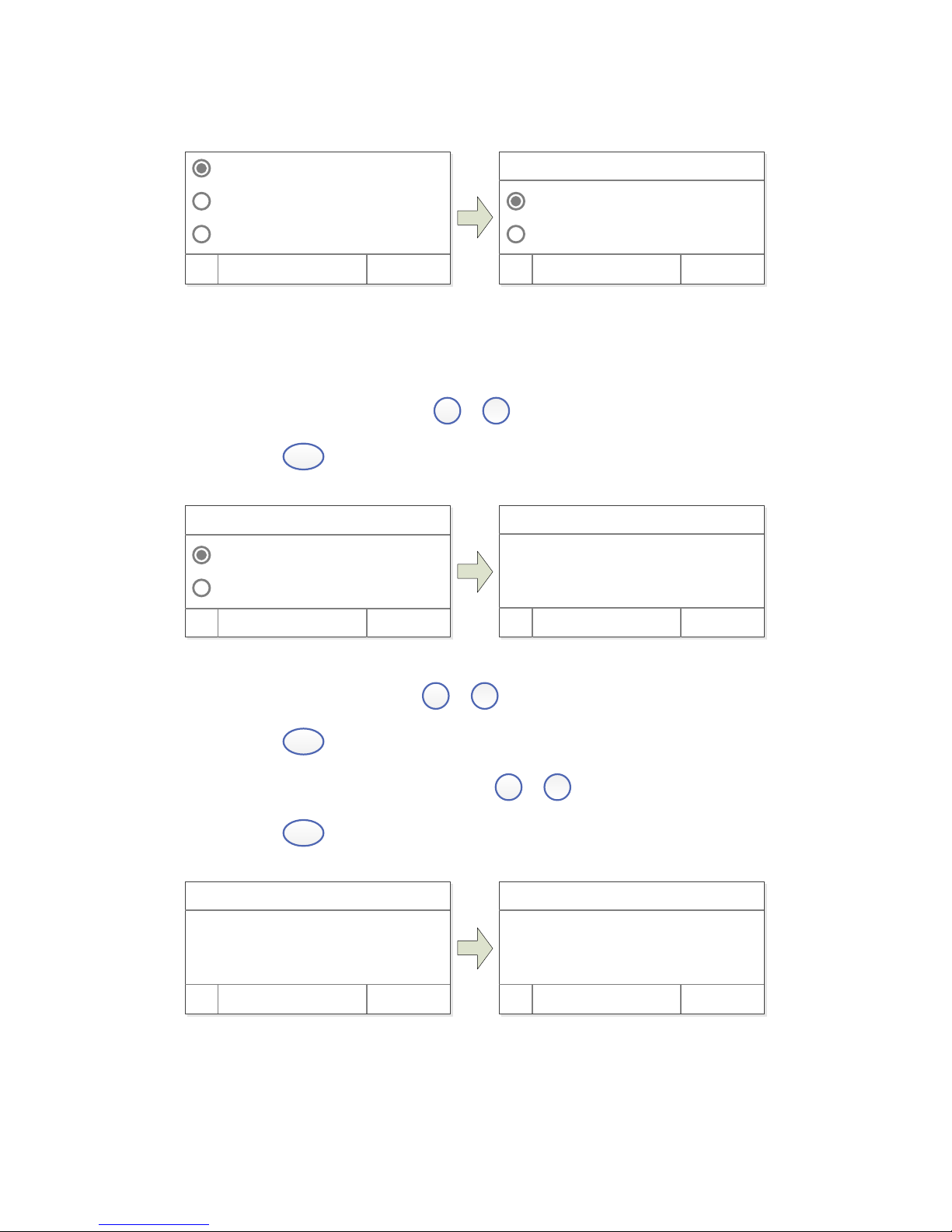
Step 2. Establish or call Standard Curve
Cr eat e Cur ve
Load Cur ve
Cl ear Cur ve
OK Cancel
Coef f i ci ent
St andar d Cur ve
OK Cancel
WL: 500. 0nm
2 methods to establish Standard Curve:
Method 1: Establish Standard Curve by inputting coefficients
1) Starts establish. Press
▲
,
▲
to select “Coefficient” , then
press
SELECT
(left) to confirm.
Coef f i ci ent
St andar d Cur ve
OK Cancel
WL: 500. 0nm
WL: 500. 0nm
Wor k WL. :
500. 0 nm
OK Cancel
2) Set wavelength. Press
▲
, ▲ to input test wavelength value,
press
SELECT
(left) to confirm.
3) Set coefficient K and B. Press
▲
,
▲
to input coefficient K,
press
SELECT
(left), same way set B.
WL: 500. 0nm
Wor k WL. :
500. 0 nm
OK Cancel
WL: 500. 0nm
Coef f i ci ent K:
00000
OK Cancel
Method 2: Establish Standard Curve by using Standard Samples
Page 15
11
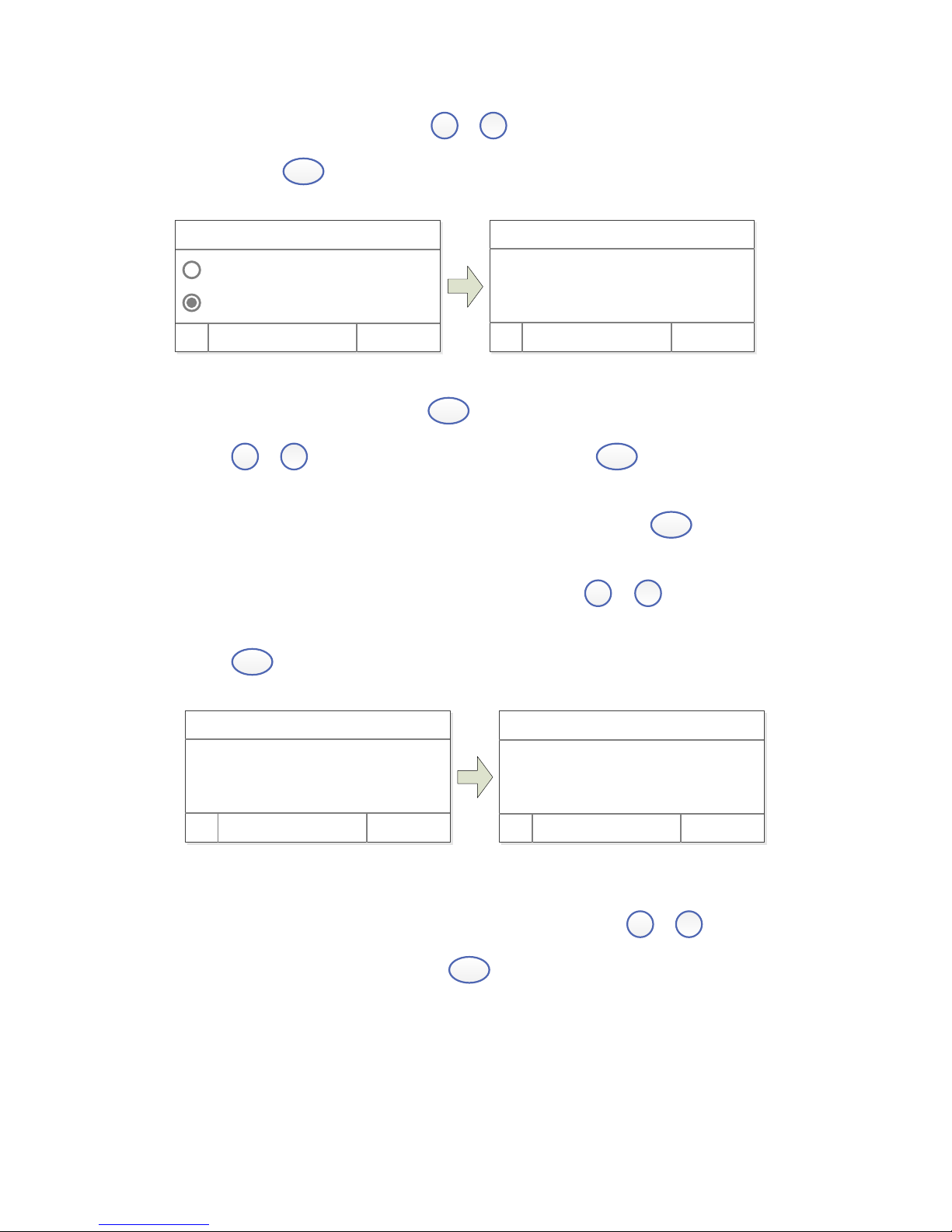
1) Starts establish. Press
▲
,
▲
to select “Standard Curve”, then
press
SELECT
(left).
Coef f i ci ent
St andar d Cur ve
OK Cancel
WL: 500. 0nm
WL: 500. 0nm 0. 000A
Pl ease i nser t Bl ank:
OK Cancel
2) Set Wavelength. Press
GOTO λ
to enter to set wavelength, Press
▲
,
▲
to input wavelength value, press
SELECT
(left) to go the
setting value.
3) Blank. Put the Reference in the light path, press
SELECT
(left) to
do blank.
4) Setup number of Standard Samples. Press
▲
,
▲
to input the
quantity of standard sample(No more than 9 standard curve.), press
SELECT
(left) to confirm.
WL: 500. 0nm
Coef f i ci ent K:
00000
OK Cancel
WL: 500. 0nm
Number : 3
OK Cancel
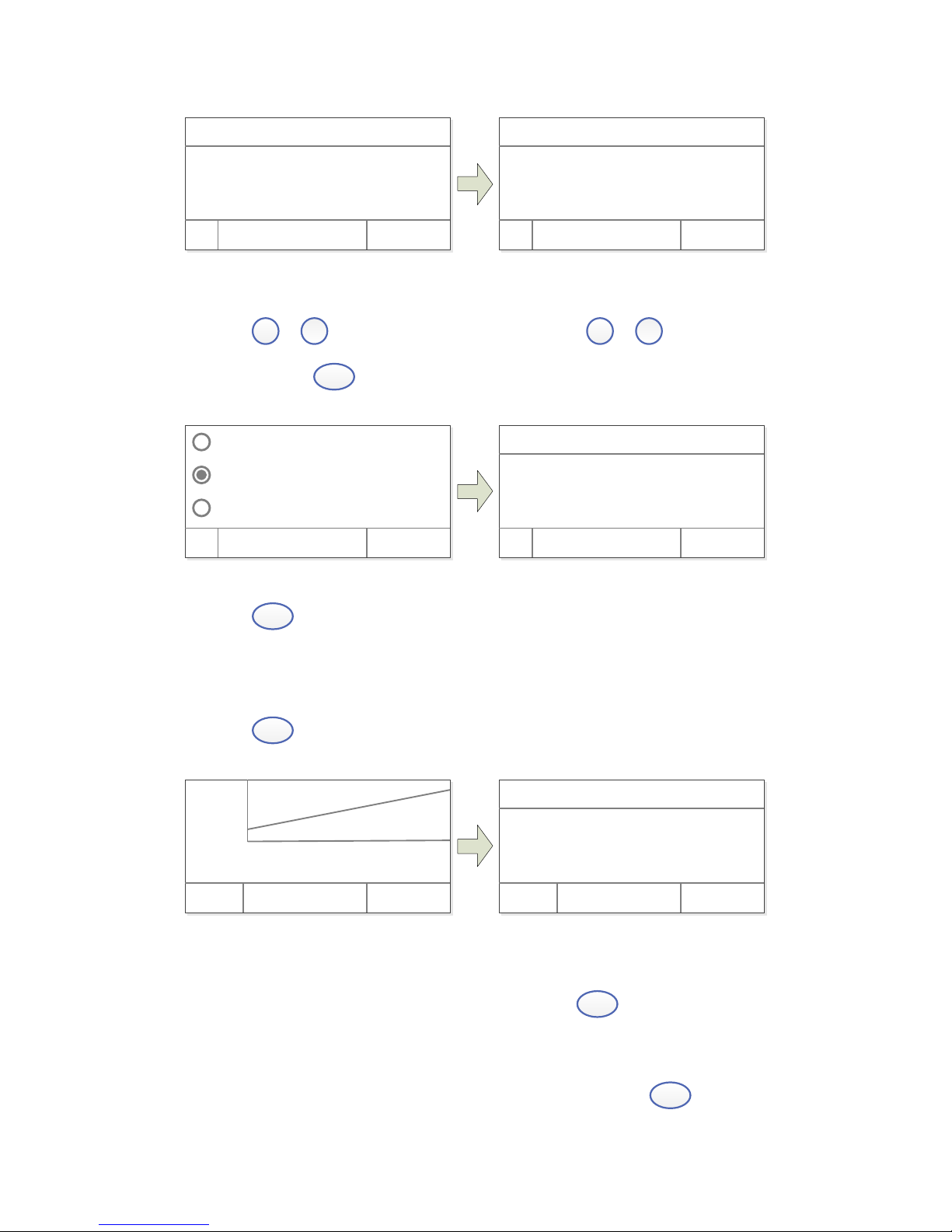
5) Calibrate Standard Samples. Put the corresponding standard samples
in the light path as the screen indicates, press
▲
,
▲
to input
the concentration, press
SELECT
(left) to confirm, to finish all
the standard samples.
Page 16
12
WL: 500. 0nm
Number : 3
OK Cancel
WL: 500. 0nm
I nser t 1# St andar d.
I nput 1# Conc: 00000
OK Cancel
Load the Stored Curve
Press
▲
,
▲
to choose “Load Curve”, press ▲,
▲
to choose the
curve, press
SELECT
(left) to confirm.
Cr eat e Cur ve
Load Cur ve
Cl ear Cur ve
OK Cancel
C=1. 000xA+0. 2 500. 0 <
C=0. 02xA+0. 32 470. 0
OK Cancel
C=KxA+B WL.
Press
SELECT
(left) to enter the test mode after building or loading
standard curve.
Step 3. Enter into Measuring Interface
Press
SELECT
(left) to enter into the Quantitation Measuring Interface.
r =0. 996, C=2. 267+1. 211
- 0. 100 0. 900
4. 000
0. 000
Test Cancel
+
+
+
WL: 500. 0nm 0. 000A
No. WL Abs. Conc.
Test Cancel
Step 4. Blank
Put the Reference in the light path, press
ZERO
to do blank.
Step 5. Measure Samples
Put the sample to be tested in the light path, press
SELECT
(left) to
Page 17
13
measure. Then the test result will display in the data sheet. Repeat
this step to finish measuring all the samples.
500. 0nm 0. 000A
No. WL Abs Conc.
1 500. 0 0. 039 0. 078
2 500. 0 0. 042 0. 084
3 500. 0 0. 041 0. 082
3. Utility
Main Interface, press
SET
to go into utility setting.
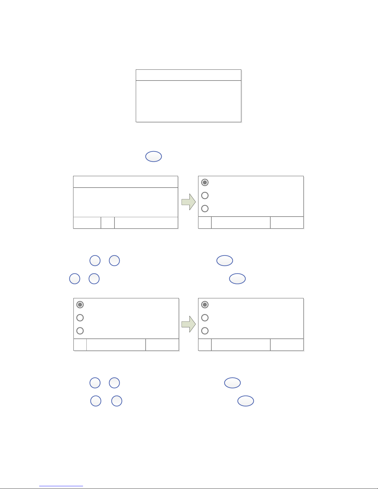
Test Mode
D2 Lamp On
W Lamp On
OK Cancel
WL: 500. 0nm 0. 000A
100. 0%T
Basi c Quant i t at i ve
Test Mode
Press
▲
,
▲
to choose “Test Mode”, press
SELECT
(left) to enter, press
▲
,
▲
to choose “Abs”, “%T”, “Energy”, press
SELECT
(left) to confirm.
Test Mode
D2 Lamp On
W Lamp On
OK Cancel
Abs
%T
Ener gy
OK Cancel
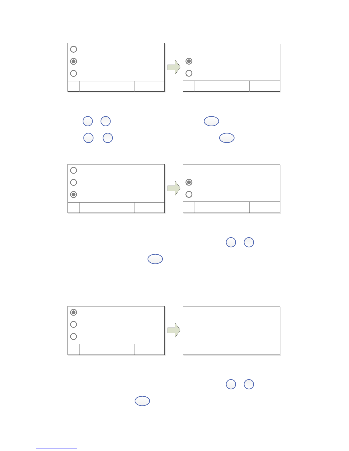
Turn On/Off D2 Lamp
Press
▲
,
▲
to choose “D2 Lamp”, then press
SELECT
(left) to enter into.
Press
▲
,
▲
to choose “On” or “Off”, press
SELECT
(left) to turn
on/off.
Page 18
14
√D2 Lamp On
On √
Of f
Test Mode
D2 Lamp On
W Lamp On
OK Cancel
OK Cancel
Turn On/Off W Lamp
Press
▲
,
▲
to choose “W Lamp”, then press
SELECT
(left) to enter into.
Press
▲
,
▲
to choose “On” or “Off”, press
SELECT
(left) to turn
on/off.
√W Lamp On
On √
Of f
Test Mode
D2 Lamp On
W Lamp On
OK Cancel
OK Cancel
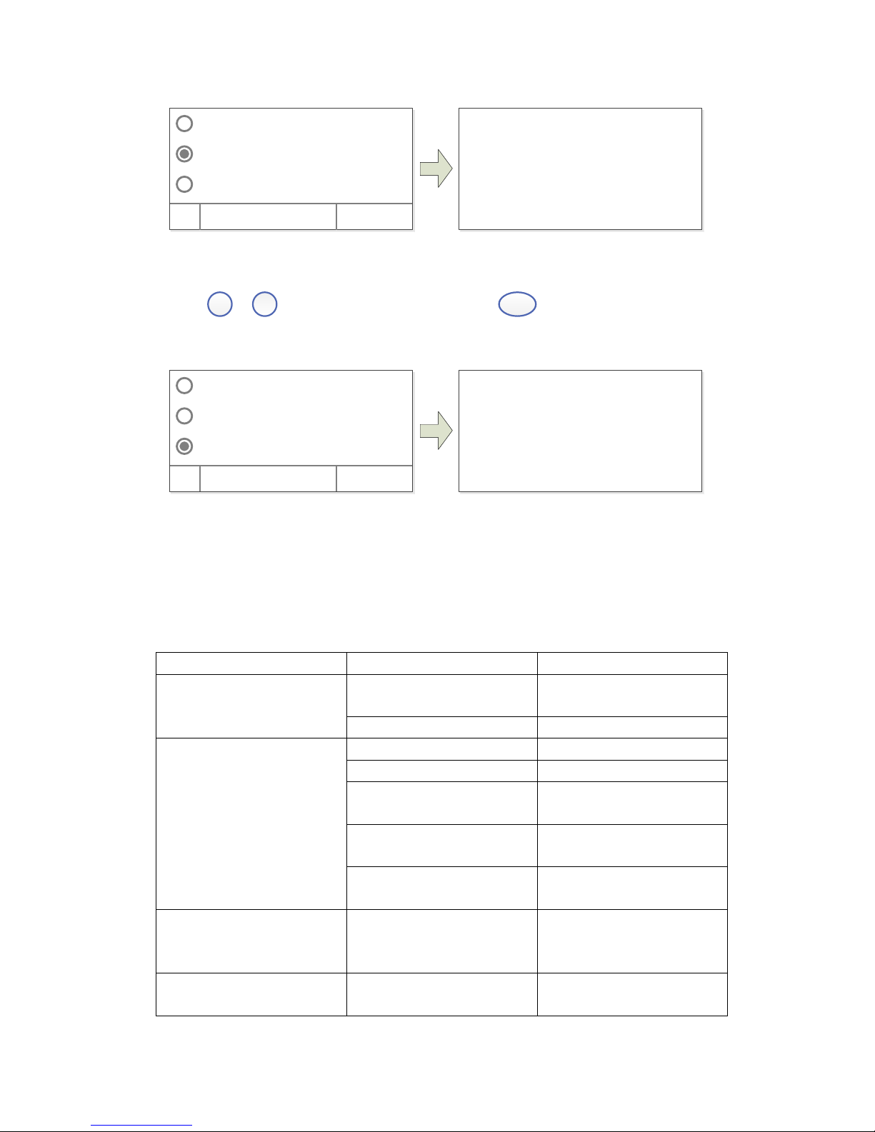
Get Dark Current
Keep the light path without anything blocking, press ▲,
▲
to choose
“Dark Current”, then press
SELECT
(left) to resample Dark Current.
Note: During the course, open the lid of the compartment is prohibited.
Get Dar k Cur r ent !
Dar k Cur r ent
Reset WL
Ver si on
OK Cancel
Reset Wavelength
Keep the light path without anything blocking, press ▲,
▲
to choose
“Reset WL”, then press
SELECT
(left) to reset wavelength.
Page 19
15
Cal i br at i ng WL!
Dar k Cur r ent
Reset WL
Ver si on
OK Cancel
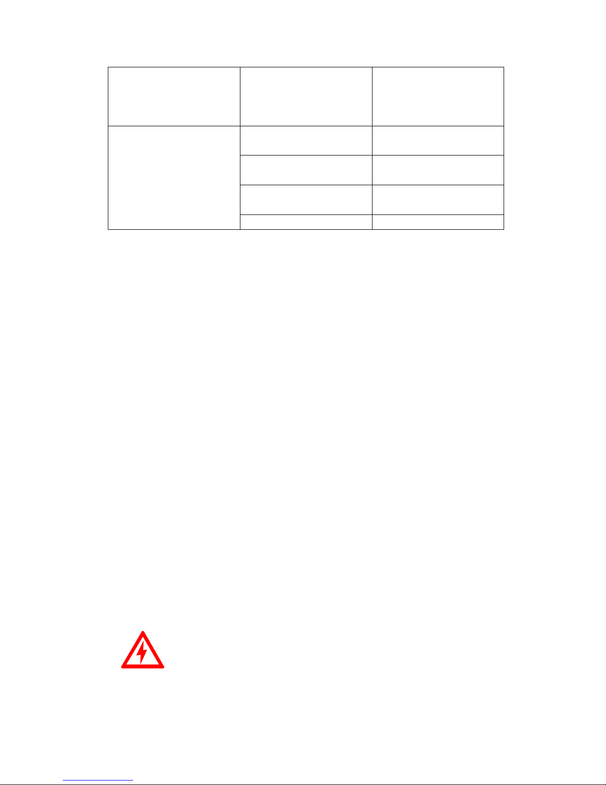
About Version
Press
▲
,
▲
to choose “Version”, press
SELECT
(left) to view version
information, press any key to return.
Sof t war e: V2. 4. 2
Har dwar e: V1. 2
Dar k Cur r ent
Reset WL
Ver si on
OK Cancel
Troubleshooting
Review the information in the table below to troubleshoot operating
problems.
Problem
Cause
Solution
Power on, no response
Power cord connection is
not reliable
Improve connectivity
Fuse burning
Replace fuse
Measurement uncertainty
Warm up is not enough
Warm up more time
Sample is not Stable
Improve the sample
The concentration of
sample is too high
Diluted sample
Power Supply Voltage Low
or not Stable
Improve the Power Supply
Lamp damage or lamp life
maturity
Replace lamp
Dark Current Error when
self-check
The lid of the
compartment is open
during self-check
Close the lid, restart
System Calibrate Failed
Something block the
Light path
Remove it, calibrate
again
Page 20
16
Power on, back light is
OK, but nothing display
on the screen or display
is not clear
Display Contrast problem
Adjust the contrast
potentiometer
Measurements inaccurate
Cuvettes were
contaminated
Clean cuvettes
Samples were
contaminated
Improve samples
Worse matching of the
cuvettes
Improve the matching of
the cuvettes
Dark current error
Resample dark current
Repair and Maintenance
1. Daily Maintain
Check the Compartment
After measurement, the cuvettes with sample solutions should be taken out
of the compartment in time. Or the volatilization of the solution would
make the mirror go moldy. Users must pay more attention to the corrosive
sample and liquid easy to volatilize. Any solution remains in the
compartment should be wiped off immediately.
Surface Clean
The cover of the instrument is with paint. Please use wet towel to wipe
off the drips on the surface immediately. Organic solution is forbidden
to be used to clean the cover. Please wipe off the dirt on the cover timely.
Clean the Cuvettes
After every test or after a solution change, the cuvettes should be cleaned
carefully, or the remains on the surface would cause measuring error.
2. Spare Parts Replacement
Replace the Fuse
Danger! Be sure to switch off the power and unplug the socket
before replacement!
Step 1. Tools preparation
Prepare a 3×75 Flat Blade screwdriver.
Page 21
17
Step 2. Switch Off the power supply
Switch off the power supply, and unplug the socket.
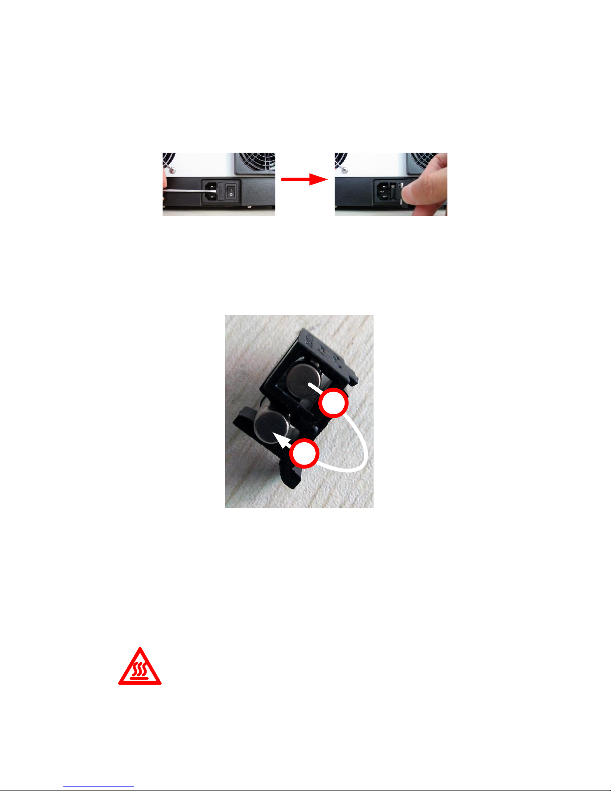
Step 3. Take out the Fuse Seat
Take out the fuse seat by the screwdriver.
Step 4. Replace a new fuse
Pick out the spare fuse (3.15A/250V) and replace it to the working
position.
1
2
Step 5. Reset the fuse seat
Replace the fuse seat in the power socket.
Step 6. Switch on the power
Plug the socket and switch on the power.
Replace Lamps
Hot! Wait 20 minutes before open the lamp chamber after power
off to avoid scald!
Step 1. Tools preparation
Prepare a 6×150mm Cross Blade screwdriver and a pair of glove.
Page 22
18
Step 2. Power Off
Switch off the power supply and unplug the socket.
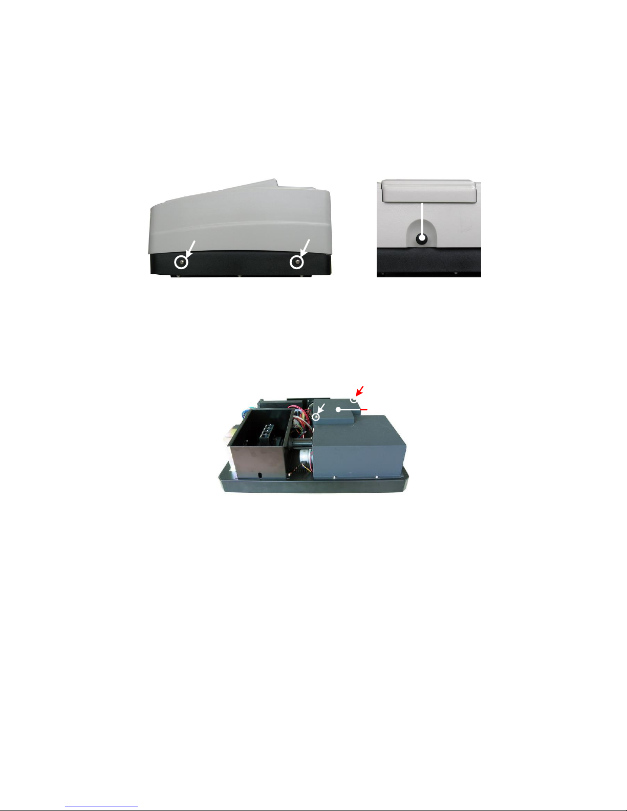
Step 3. Open the cover
Unscrew the 4 screws indicated(Each side with 2 screws) and remove
the cover.
Rod
Step 4. Open the cover of the light chamber
Unscrew the 2 screws on the light chamber cover and remove it.
Li ght
chamber
Step 5. Replace the D2 lamp
Unscrew the 2 screws on the D2 Flange (No.1), unplug the connector
in the Power Board (No. 2) and remove the D2 lamp. Draw on the cotton
glove and replace a new lamp. Fix the 2 screws and plug the connector
again.
Page 23
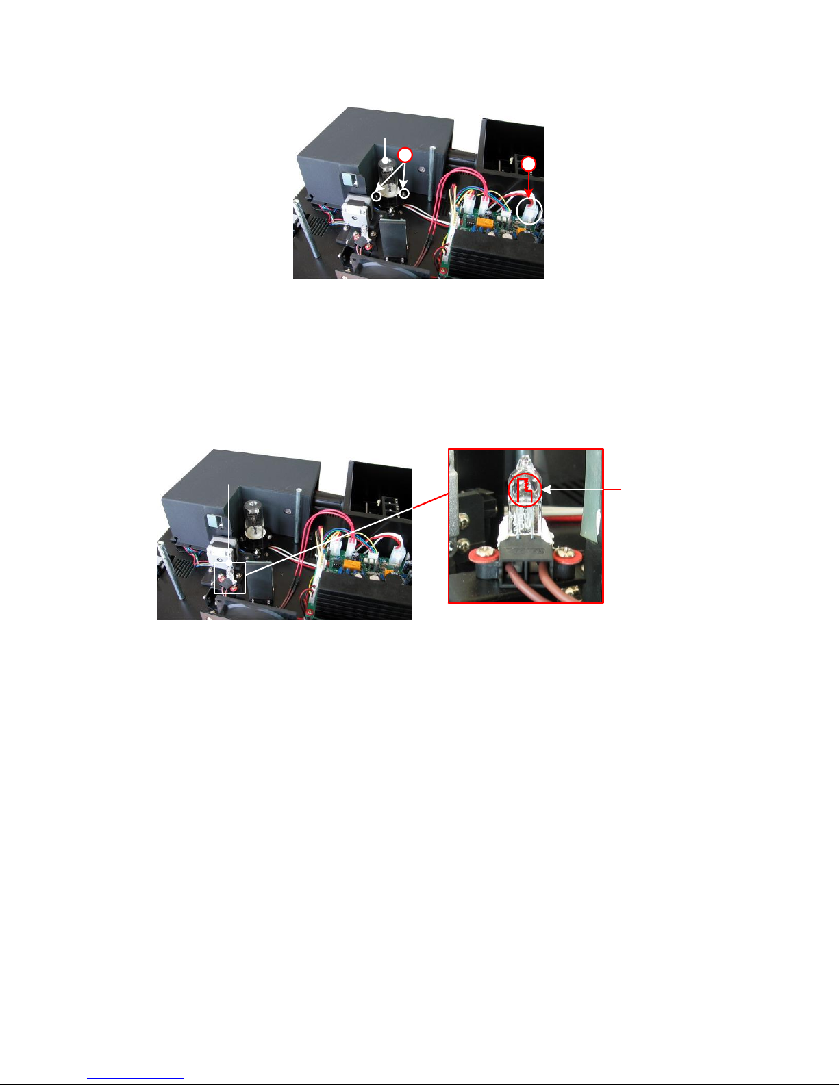
19
D2
Lamp
1
2
Step 6. Replace W lamp
Pull out the defected W lamp and draw on the cotton glove. Insert the
new W lamp as deep as possible on the lamp seat. Be sure to keep the
filament in the same direction as the old one face.
W
Lamp
Fi l ament
Adjust the position of the W lamp
Switch on the power(the Switch Mirror should be placed to the position
as indicates). Observe the entrance facular, and it should in the center
of the entrance hole. If the facular deviate to Left or Right, then
loosen the No.1 screws in Fig. 5-8 and move the lamp seat to Left or
Right until it focus on the center of the slot. Then fix the screws.
If the facular deviate to Up and Down, then loosen the No.2 screws
and move the lamp seat Up and Down until the facular focus on the center
of the slot. Then fix the No. 2 screws again.
Page 24
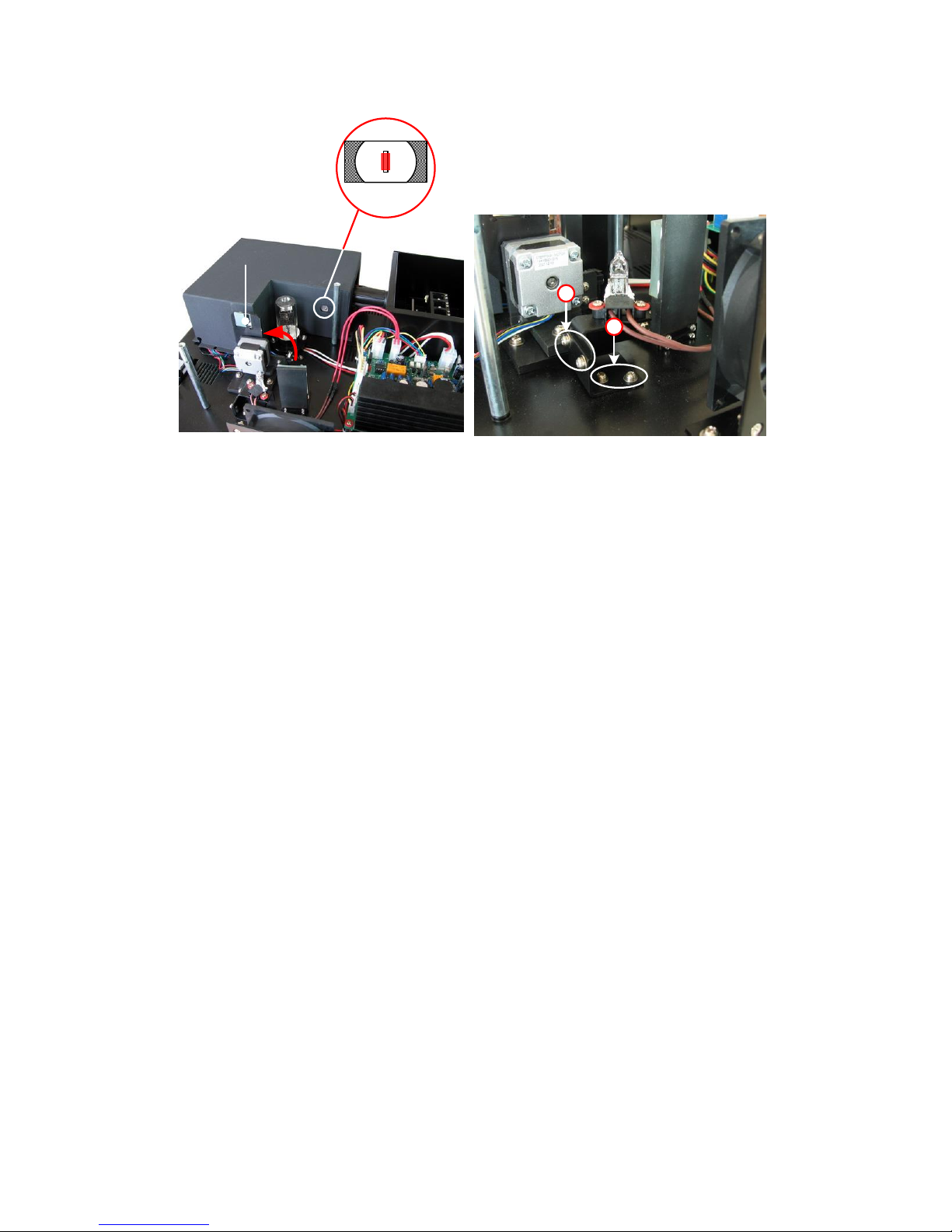
20
Swi t ch
Mi rr or
Ri ght Posi t i on
2
1
Step 7. Finish
Reset the cover of the light chamber and fix the screws. Reset the
cover of the instrument and fix the screws. Recover the Pole in the
compartment, then the course finished.
Warranty
We warrant that this product will be free from defects in material and
workmanship for a period of one (1) year from date of purchase. If a defect
is present, we will, at its option, repair, replace, or refund the purchase
price of this product at no charge to you, provided it is returned during
the warranty period. This warranty does not apply if the product has been
damaged by accident, abuse, misuse, or misapplication, or from ordinary
wear and tear.
For your protection, items being returned must be insured against possible
damage or loss. This warranty shall be limited to the replacement of
defective products. IT IS EXPRESSLY AGREED THAT THIS WARRANTY WILL BE IN
LIEU OF ALL WARRANTIES OF FITNESS AND IN LIEU OF THE WARRANTY OF
MERCHANTABILITY.
Page 25
21
Equipment Disposal
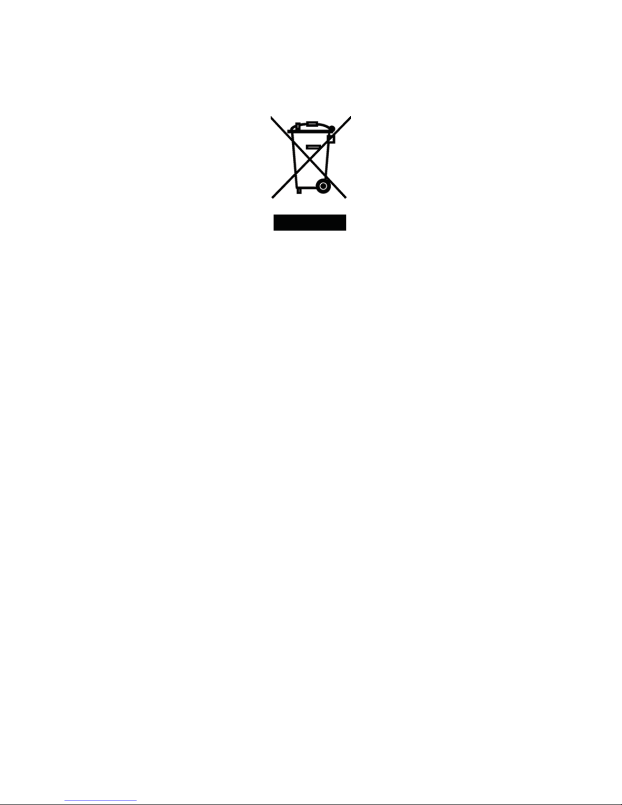
This equipment is marked with the crossed out wheeled bin symbol to indicate
that this equipment must not be disposed of with unsorted waste.
Instead it's your responsibility to correctly dispose of your equipment
at lifecycle -end by handling it over to an authorized facility for separate
collection and recycling. It's also your responsibility to decontaminate
the equipment in case of biological, chemical and/or radiological
contamination, so as to protect from health hazards the persons involved
in the disposal and recycling of the equipment.
For more information about where you can drop off your waste of equipment,
please contact your local dealer from whom you originally purchased this
equipment.
By doing so, you will help to conserve natural and environmental resources
and you will ensure that your equipment is recycled in a manner that
protects human health.
Thank you!
Page 26

Page 27

Page 28

Giorgio Bormac S.r.l.
Add.: VIA DELLA MECCANICA, 25
41012 CARPI (MO) ITALY
Tel.: +39 059 653 274
Fax: +39 059 653 282
 Loading...