

Page 1
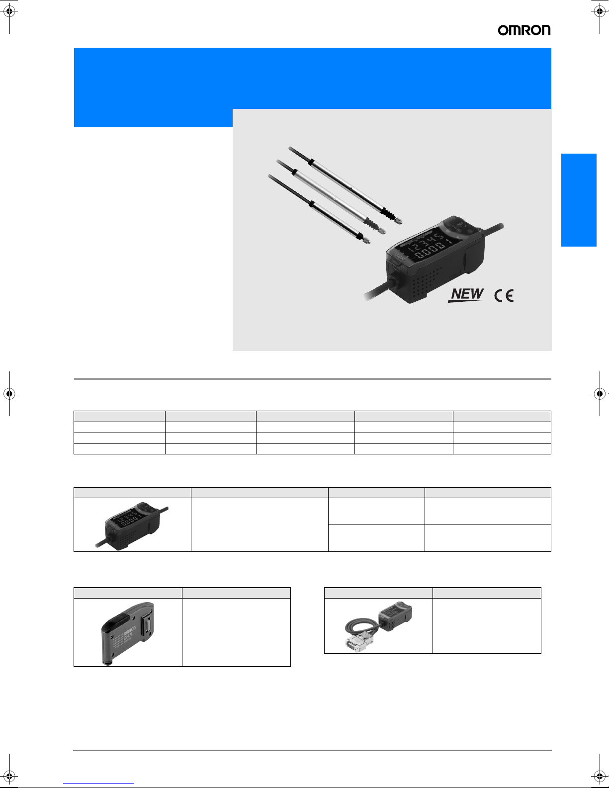
Smart Sensor High precision contact type ZX-T Series
ZX-T Series
ZX-T Series
Ordering Information
Sensors
Sensor Heads
Size Typ e Sensing distance Resolution (See note.) Model
6 dia. Short type 1 mm 0.1 µm ZX-TDS01T
6 dia. Standard type 4 mm 0.1 µm ZX-TDS04T
6 dia. Low measurement type 4 mm 0.1 µm ZX-TDS04T-L
Note:The resolution refers to the minimum value that can be read when a ZX-TDA@1 Amplifier Unit is connected.
Amplifier Units
Appearance Power supply Output type Model
DC NPN ZX-TDA11
PNP ZX-TDA41
Accessories (Order Separately)
Calculating Unit ZX-series Communicationys Interface Unit
Appearance Model
ZX-CAL2
Appearance Model
ZX-SF11
B-77ZX-T Series
Page 2
SmartMonitor Sensor Setup Tool for Personal Computer
Connection
Appearance Name Model
ZX-series
ZX-SF11
Communications
Interface Unit
Cables with Connectors on Both Ends (for Extension)*
Cable length Model Quantity
1 m ZX-XC1A
14 m ZX-XC4A
8 m ZX-XC8A
Note: *Robot Cable models are also available.
The model numbers are ZX-XC@R.
Preamplifier Mounting Brackets
ZX-series Communications Interface
Unit + ZX-series
+
CD-ROM
Sensor Setup Software Basic
CD-ROM ZX-series Sensor
Setup Software
Note: *1. When using the ZX-TDA11/41 with the SmartMonitor, either the
ZX-SFW11EV3 or the ZX-SW11EV3 SmartMonitor must be used.
Earlier versions cannot be used.
Note: *2. The ZX-SFW11EV3 SmartMonitor can be used for parameter setting,
data logging and waveform monitoring.
ZX-
SFW11EV3
*1, *2
ZX-SW11EV3
*2
Appearance Model Remarks
ZX-XBT1 Attached to each
ZX-XBT2 For DIN track mount-
Sensor Head
ing
Cables with Connectors on Both Ends (for Extension)
Cable length Model Quantity
1 m ZX-XC1A 1
4 m ZX-XC4A
8 m ZX-XC8A
Specifications
Sensor Heads
Item ZX-TDS01T ZX-TDS04T ZX-TDS04T-L
Measurement range 1 mm 4 mm
Maximum actuator travel distance Approx. 1.5 mm Approx. 5 mm
Resolution (See note 1.) 0.1 µm
Linearity (See note 2.) 0.3% F.S.
Operating force (See note 3.) Approx. 0.7 N Approx. 0.25 N
Degree of protection (Sensor
Head)
Mechanical durability 10,000,000 operations min.
Ambient temperature Operating: 0° C to 50° C (with no icing or condensation)
Ambient humidity Operating and storage: 35% to 85% (with no icing or condensation)
Temperature
characteristic
(See note 4.)
Weight (packed state) Approx. 100 g
Materials Sensor Head Stainless steel
Accessories Instruction manual, Preamplifier Mounting Brackets (ZX-XBT1)
Note 1. The resolution is given as the minimum value that can be read when a ZX-TDA@1 Amplifier Unit is connected. This value is taken 15 min-
utes after turning ON the power with the average number of operations set to 256.
2. The linearity is given as the error in an ideal straight line displacement output.
3. These figures are representative values that apply for the measurement mid-point, and are for when the provided actuator is used, with
the actuator moving downwards. If the actuator moves horizontally or upwards, the operating force will be reduced. Also, if an actuator
other than the standard one is used, the operating force will vary with the weight of the actuator itself.
4. These figures are representative values that apply for the mid-point of the measurement range.
Sensor Head 0.03% F.S./° C
Preamplifier 0.01% F.S./° C
Preamplifier Polycarbonate
IEC60529, IP67 IEC60529, IP54
Storage: −15° C to 60° C (with no icing or condensation)
B-78 Displacement sensors / Width-measuring Sensors
Page 3
Amplifier Units
Item ZX-TDA11 ZX-TDA41
Measurement period 1 ms
Possible average count set-
tings (See note 1.)
Linear output (See note 2.) Current output: 4 to 20 mA/F.S., Max. load resistance: 300 Ω
Judgement outputs
(3 outputs: HIGH/PASS/
LOW)
Zero reset input, timing input, reset input, judgement
output hold input
Function - Measurement value display- Present value/set value/output value display
Indicators Judgement indicators: High (orange), pass (green), low (yellow), 7-segment main digital display (red), 7-segment
Power supply voltage 12 to 24 VDC ±10%, Ripple (p-p): 10% max.
Current consumption 140 mA max. (with Sensor connected), For 24-VDC power supply voltage: 140 mA max. (with Sensor connected)
Ambient temperature Operating and storage: 0 to 50° C (with no icing or condensation)
Temperature characteristic 0.03% F.S./° C
Connection method Prewired (standard cable length: 2 m)
Weight (packed state) Approx. 350 g
Materials Case: PBT (polybutylene terephthalate), Cover: Polycarbonate
Note 1. The response speed of the linear output is calculated as the measurement period × (average count setting + 1).
The response speed of the judgement outputs is calculated as the measurement period
2. The output can be switched between a current output and voltage output using a switch on the bottom of the Amplifier Unit.
3. Setting is possible via the monitor focus function.
4. A Calculating Unit (ZX-CAL2) is required.
1, 16, 32, 64, 128, 256, 512, or 1,024
Voltage output: ±4 V (±5 V, 1 to 5 V (See note 3.)), Output impedance: 100 Ω
NPN open-collector outputs, 30 VDC, 30 mA max.
Residual voltage: 1.2 V max.
ON: Short-circuited with 0-V terminal or 1.5 V or less
OFF: Open (leakage current: 0.1 mA max.)
PNP open-collector outputs, 30 VDC, 30 mA max.
Residual voltage: 2 V max.
ON: Supply voltage short-circuited or supply voltage of
1.5 V or less
OFF: Open (leakage current: 0.1 mA max.)
- Display reverse- ECO mode - Number of display digit changes
- Sample hold- Peak hold- Bottom hold, peak-to-peak hold
- Self-peak hold - Self-bottom hold- Zero reset
- Initial reset- Direct threshold value setting- Position teaching
- Hysteresis width setting- Timing inputs- Reset input
- Judgement output hold input - Monitor focus- (A-B) calculations (See note 4.)
- (A+B) calculations (See note 4.) - Sensor disconnection detection
- Zero reset memory- Function lock- Non-measurement setting
- Clamp value setting- Scale inversion- Zero reset indicator
- Span adjustment- Warming-up display- Pressing force alarm
sub-digital display (yellow), power ON (green), zero reset (green), enable (green)
× (average count setting + 1).
ZX-T Series
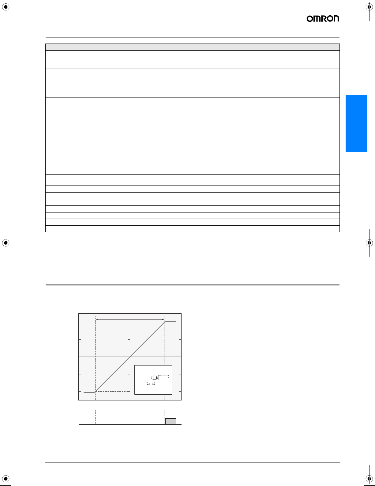
Characteristic Data
Output Characteristics
Voltage/Current Output
ZX-TDS01T/-S04T/-S04T-L
4 V
Voltage output
0 V
−4 V
(−2 mm)
High/Low output
Note:To prevent destroying the Sensor Head, both the high and low judgment outputs will light if 101% of the upper limit of the measurement
ON
OFF
distance is reached.
Measurement distance (F.S)
Analog output
Voltage/current
Displacement direction
Center
+−
(Pushed)(Released)
(+2 mm)
20 mA
Current output
12 mA
4 mA
Displacement 0 mm +0.5 mm
−0.5 mm
B-79ZX-T Series
Page 4

I/O Circuit Diagrams
p
t
r
NPN Amplifier Unit: ZX-TDA11 PNP Amplifier Unit: ZX-TDA41
Internal circuit
Current/voltage
output selector
Connectors
Amplifier Unit
100 Ω
Current
output
(4 to 20mA)
Voltage
output
±4V
Brown 12 to 24 V DC
HIGH
judgement
White
output
PASS judgement
output
Green
LOW
Gray
output
GND (0V)
Blue
Judgement output
hold input
Pink
Purple
Timing input
Orange
Zero reset input
Red Reset input
Black Linear output
Shield Linear ground
Brown
12 to 24 VDC
Blue
GND (0 V)
White
HIGH judgement output
Green
PASS judgement output
Gray
LOW judgement output
Black
Linear output
Shield
Linear output GND
Pink
Judgement output hold inpu
Orange
Zero reset input
Purple
Timing input
Red
Reset in
Load
judgement
ut
Load
Load
Current output:
Load
300 Ω max.
Voltage output:
10 kΩ min.
12 to
24 V DC
Brown 12 to 24 V DC
HIGH
judgement
White
Internal circuit
Current/voltage
output selector
100 Ω
Current
output
(4 to 20mA)
Voltage
output
±4V
output
PASS judgement
output
Green
LOW
Gray
Blue
Pink
Purple
Orange
Red Reset input
Black Linear output
Shield Linear ground
judgement
output
GND (0V)
Judgement output
hold input
Timing input
Zero reset input
Load
Load
Load
Current output:
300 Ω max.
Voltage output:
10 kΩ min.
Load
12 to
24 V DC
Note 1. Use a stabilized power supply separate from other devices
and power systems for the Amplifier Unit, particularly when
high resolution is required.
2. Always wire correctly. Incorrect wiring may damage the Unit.
Use a different ground for the linear output from the normal
ground.
3. The blue line (0 V) is the 0 V power supply line. The shield
wire (linear output GND) is used together with the black line
(linear output) to connect the linear output. Wire these lines
correctly. Always ground the linear output terminal even when
the linear output is not used.
Part Names
Sensor Heads
ZX-TDS01T
ZX-TDS04T
ZX-TDS04T-L
Sensor head
Amplifier Unit
ZX-TDA11
ZX-TDA41
Input cable
(with connector)
Display area
Preamplifier
Output cable
(with connector)
Controls
Output cable
Connector
(Cover opens and closes)
Calculating Unit
ZX-CAL2
Display area
Connecto
B-80 Displacement sensors / Width-measuring Sensors
Page 5

Options (Actuators)
Model Type (material) Screw section Appearance Application Applicable
D5SN- TB1 Ball type (steel) Female screw
M2.5 x 0.45
TB2 Ball type (
carbide steel)
Female screw
M2.5 x 0.45
TB3 Ball type (ruby) Female screw
M2.5 x 0.45
TN1 Needle type
(carbide steel)
Male screw
M2.5 x 0.45
TF1 Flat (carbide steel) Male screw
Measuring ordinary flat surfaces (standard actuator supplied with the ZX-TDS
Series)
Measurements where abrasion resistance is critical
Measured objects: Carbide (HR90) or
lower.
Measurements where abrasion resistance is critical
Measured objects: Carbide (HR90) or
higher.
Measuring the bottom of grooves and
holes
Measuring spherical objects
M2.5 x 0.45
TA Conversion Adapt-
er (stainless steel)
Through-hole female screw
M2.5 x 0.45
Mounting D5SN-TN1/-TF1 or commercially available actuators on ZX-TDSseries Sensors
Note: Replacement possible Conversion Adapter required
Dimensions
D5SN-TB1/TB2/TB3 D5SN-TN1 D5SN-TF1 D5SN-TA
3.5 dia.
SR1.5
6.5±0.2
3.5
Crisscross pattern m0.2
C0.3
5.5
4.5 dia.
M2.5
1 dia.
37
Carbide steel
(15)
10
5
M2.5 × 0.45
5 dia.
5.2 dia.
4.3 dia.
Carbide steel
(10)
55
3.3
M2.5 × 0.45
Two, C0.2
Grooves
12
Sensor
(See note.)
ZX-TDS@T
m0.2
5 dia.
M2.5
(Through-hole)
ZX-T Series
Mounting Jigs
Recommended Mounting Jigs
for ZX-TDS Sensors
10
6H7 dia.
1.5
4
20
26
Tightening torque: 0.6 to 0.8 N·m (M3 screws)
Material: Aluminum
A
6.5 dia.
8
32
A
8
3.5 dia.
A-A
Mounting Jigs for an 8-diameter Stand
+0.01
6 dia.
Base jig
60°
0
0
8 dia.
−0.03
Supported at
3 points
Tightening force:
100 N max.
15
5
1
12 dia.
Mounting width:
8 mm min.
1
3.5
M3
Material: Brass
Two, 3.5 dia.
18
Mounting with 3-point Support
Mounting jig
Sensor Head
cross-section
B-81ZX-T Series
Page 6

Replacing Actuators
Be careful not to damage the rubber boot with pliers or other tools
when replacing the actuator.
1. Remove the standard actuator.
• Hold the plunger’s D-cut section with radio pliers or a similar tool
while removing the actuator.
• If the replacement must be performed by holding the Sensor Head
itself, ensure that a torque exceeding 0.15 N·m is not applied.
Applying excessive torque may have an adverse affect on plunger
operation.
Width: 1 mm
Rubber boot
2. Mount the commercial actuator to the Conversion Adapter.
• Tighten the actuator securely, and ensure that there is no loose-
ness.
• If necessary, apply a screw-locking agent.
(Recommended: Three-Bond 1401B)
D-cut section
Radio pliers or
a similar tool
Conversion Adapter
(D5SN-TA)
Screw-locking agent required
Commercially available
actuator
(e.g., one with a flat end)
3. Mount the Conversion Adapter to the plunger.
• Hold the plunger’s D-cut section with radio pliers or a similar tool
while mounting and securing the Conversion Adapter.
• If the replacement must be performed by holding the Sensor Head
itself, ensure that a torque exceeding 0.15 N·m is not applied.
Applying excessive torque may have an adverse affect on plunger
operation.
Precautions
Design Precautions
• Conform to the specified ratings and performance. Refer to Specifi-
cations on page B-78 for details.
• Measurements may not be possible or may not be accurate for
some materials and shapes.
• The Sensor will be destroyed if the Actuator is pressed too far. Do
not use the Actuator past the point where a pressing force alarm
(OVER) is displayed.
• Do not remove the rubber boot. Without the rubber boot, foreign
matter may enter the Sensor Head, possibly causing the Sensor
Head to malfunction.
• Use suitable torque and force when mounting the Sensor. Refer to
page B-81 for details.
• The Sensor may be destroyed if excessive force is applied.
Environment
• Do not operate the product in locations subject to flammable or
explosive gases.
• In order to ensure safe operation and maintenance, do not install
the product in the vicinity of high-voltage devices or power equipment.
Wiring
• Do not use the product at voltages exceeding the rated values.
Doing so may result in damage.
• Do not connect the product to an AC power supply or connect the
power supply in reverse.
• Do not short-circuit the load for open-collector output.
Correct Use
• System Design
Warming Up
After turning ON the power, allow the Smart Sensor to warm up for
15 minutes minimum prior to use.
Measurements
Do not expose the plunger to forces exceeding the limits in the following diagram. Doing so may damage the plunger.
ZX-TDS-Series Sensors
30 N 30 N 1 N 0.15 N·m
• Adjustments
Settings
When setting the threshold value with the Smart Sensor connected
to an external device, turn ON the Amplifier Unit's judgement output
hold input to prevent the judgement from being output to the external
device.
• Compatibility
Sensors and Amplifier Units are mutually compatible. Sensors can
be added or replaced individually.
• Influence of High-frequency Electromagnetic Fields
Using the product in the vicinity of devices that generate high-frequency electromagnetic fields, such as ultrasonic cleaning equipment, high-frequency generators, transceivers, mobile phones, and
inverters, may result in malfunction.
Other Precautions
Do not attempt to disassemble, repair, or modify the product.
Dispose of the product using standard procedures for industrial
waste.
These Sensors are not compatible with the ZX-L@@ Smart Sensors
(laser type). Do not connect combinations of ZX-E@@ Smart Sensors and ZX-T@@ Smart Sensors.
B-82 Displacement sensors / Width-measuring Sensors
Page 7

Wiring
• Wiring Check
After wiring is completed, before turning ON the power, confirm that
the power supply is connected correctly, that there are no faulty connections, such as load short-circuits, and that the load current is correct. Incorrect wiring may result in failure.
Dimensions
Sensors
ZX-TDS01T
Vinyl-insulated round cable
3.7 dia., standard length: 2 m
* Measurement range: 11.2 to 12.2 (TYP)
Vinyl-insulated round cable
0
6
−0.1
3.7 dia., standard length: 2 m
dia.
* Measurement range: 14.9 to 18.9 (TYP)
ZX-TDS04T
ZX-TDS04T-L
4.5 dia.
SR1.5
5.95
4.5 dia.
SR1.5
Measurement
range*
57.1
13.1
0
6
−0.1
41.6 ±0.4
44.6 ±0.8
±
1
Measurement
range*
dia.
63.4 ±0.4
66.4 ±0.8
86 ±1.5
• Cable Extension
Do not extend the cable for the Sensor and the Amplifier Unit to a
length exceeding 10 m. Use a ZX-XC@A Extension Cable (sold separately) to extend the Sensor’s cable. Extend the Amplifier Unit’s
cable using a shielded cable of the same type.
• Power Supply
When using a commercially available switching regulator, ground the
FG (frame ground) terminal.
If the power supply line is subject to surges, connect a surge
absorber that meets the conditions of the operating environment.
Vinyl-insulated round cable
5.2 dia., standard length: 200 mm
15 dia.
Connector
16
46
Vinyl-insulated round cable
5.2 dia., standard length: 200 mm
15 dia.
Connector
16
46
ZX-T Series
Amplifier Unit
ZX-TDA11
ZX-TDA41
30
15.5 dia.
13.2
44
133
3
Vinyl-insulated round cable
5.1 dia., standard length: 100 mm
11.7
64.3
13 36.8
29
4.24.2
15.8
Vinyl-insulated round cable
5.2 dia., 10 conductors,
(conductor cross-section:
0.09 mm
standard length: 2 m
Current/voltage switch
2.2
(Factory-set to voltage output)
2
, insulator diameter: 0.7-mm dia.),
11.7
Voltage output
31.5
B-83ZX-T Series
Page 8

Accessories (Order Separately)
0.1
3
Preamplifier Mounting Bracket (Supplied with Each Sensor)
ZX-XBT1
ZX-XBT2 (For DIN Track Mounting)
4.8
3.2
Four, 1.6R
27
(91.1)
Material: Stainless steel
(16.4)
(28.1)
Mounting Hole Cutout Dimensions
Two, M
(38)
M3 x 8 pan-head screw (with M3 spring washer)
(91.1)
75
29
11.8
6.210
1.81.8
58
84.8
Material: Stainless steel
9.4
11.435.3
(28.1)
(16.4)
10
ALL DIMENSIONS SHOWN ARE IN MILLIMETERS.
To convert millimeters into inches, multiply by 0.03937. To convert grams into ounces, multiply by 0.03527.
Cat. No. E345-E2-02-X
In the interest of product improvement, specifications are subject to change without notice.
B-84 Displacement sensors / Width-measuring Sensors
 Loading...