

Omron ZX-LD40, ZX-LD100, ZX-LD300, ZX-LD40L, ZX-LD100L Datasheet
...
ZX Series (ZX-L-N) Smart Sensors (Laser T ype) 1
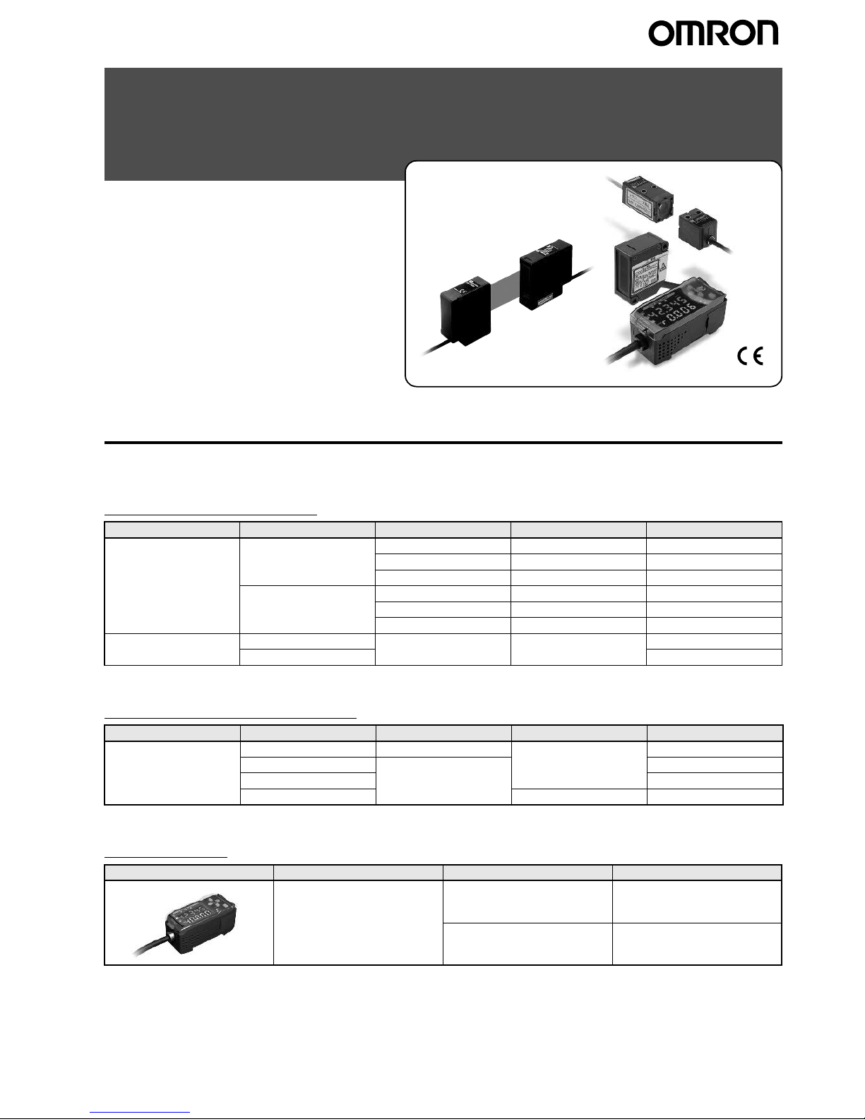
Smart Sensors (Laser Type)
ZX Series (ZX-L-N)
.
Ordering Information
■Sensors
Sensor Heads (Reflective)
Sensor Heads (Through-beam)
Amplifier Units
Note: Compatible connection with the Sensor Head.
Optical system Beam shape Sensing distance Resolution*1 Model
Diffuse reflective Spot beam 40
±10 mm 2 µm ZX-LD40
100
±40 mm 16 µm ZX-LD100
300
±200 mm 300 µm ZX-LD300
Line beam 40
±10 mm 2 µm ZX-LD40L
100
±40 mm 16 µm ZX-LD100L
300
±200 mm 300 µm ZX-LD300L
Regular reflective Spot beam 30
±2 mm 0.25 µm ZX-LD30V
Line beam ZX-LD30VL
*1.F or an average count of 4,096.
Optical system Measuring width Sensing distance Resolution*1 Model
Through-beam 1-mm dia. 0 to 2000 mm 4
µm ZX-LT001
5 mm 0 to 500 mm ZX-LT005
10 mm ZX-LT010
30 mm 12
µm ZX-LT030
*1.For an average count of 64.
Appearance Power supply Output type Model
DC NPN ZX-LDA11-N
PNP ZX-LDA41-N

2 ZX Series (ZX-L-N) Smart Sensors (Laser Type)
Accessories (Order Separately)
Calculat ing Unit
Side-view Attachments
SmartMonitor Sens or Setup Tool for
Personal Computer Connection
*1. When using the ZX-LDA11-N/41-N with the SmartMonitor, either the ZX-
SFW11EV3 or the ZX-SW11EV3 SmartMonitor must be used. Earlier versions cannot be used.
*2. The ZX-SFW11EV3 SmartMonitor can be used only to set functions and
monit o r wave forms.
Cables with C onnectors on Both Ends (for
Extension)*1
*1. Robot Cable models are also available. The model numbers are ZX-XC@R.
*2.For use only with Reflective Sensors.
Appearance Model
ZX-CAL2
Appearance Applicable
Sensor Head
Model
ZX-LT1001/
LT005
ZX-XF12
ZX-LT010 ZX-XF22
Appearance Name Model
ZX-series Communications Interface
Unit
ZX-SF11
ZX-series Communications Interface
Unit + ZX-series
Sensor Setup Software Basic
ZX-SFW11EV3
*1*2
CD-ROM ZX-series Sensor
Setup Software
ZX-SW11EV3
*1
Cable length Model Quantity
1 m ZX-XC1A 1
4 m ZX-XC4A
8 m ZX-XC8A
9 m *2 ZX-XC9A
+
CD-ROM
ZX Series (ZX-L-N) Smart Sensors (Laser T ype) 3
Specifications
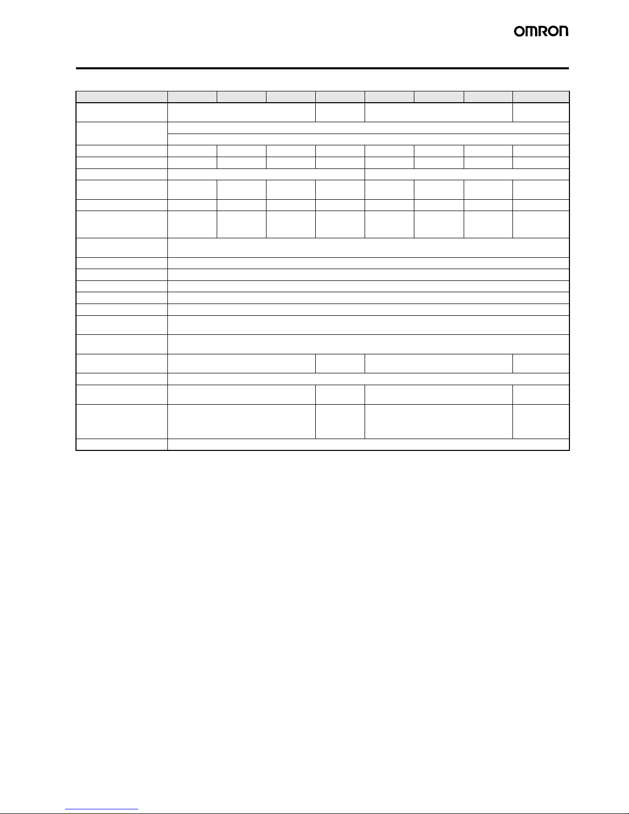
■Sensor Heads (Reflective)
Note: Highly reflective objects can result in incorrec t detection by causing out-of-range measurements.
Item Model ZX-LD40 ZX-LD100 ZX-LD300 ZX-LD30V ZX-LD40L ZX-LD100L ZX-LD300L Z3X-LD30VL
Optical system Diffuse reflective Regular re-
flective
Diffuse reflective Regular reflec-
tive
Light source (wave
length)
Visible-light semiconductor laser with a wavelength of 650 nm and an output of 1 mW max.
EN class 2, FDA class II
Measurement point 40 mm 100 mm 300 mm 30 mm 40 mm 100 mm 300 mm 30 mm
Measurement range
±10 mm ±40 mm ±200 mm ±2 mm ±10 mm ±40 mm ±200 mm ±2 mm
Beam shape Spot Line
Beam size*1
*1.Beam size: The beam size is defined by 1/e
2
(13.5%) of the strength of the beam at the beam center (measured value). Incorrect detection may
occur if there is light leakage outside the defined spot and the material around the sensing object is more reflective than the sensing object.
50-
µm dia. 100-µm dia. 300-µm dia. 75-µm dia. 75 µm x 2
mm
150 µm x 2 mm450 µm x 2 mm100 µm x 1.8
mm
Resolution*2
*2.Resolution: The resolution is the deviation (
±3σ) in the linear output when connected to the ZX-LDA Amplifier Unit. (The resolution is measured
with the standard reference object (white ceramic), at the measurement point with the ZX-LDA set for an average count of 4,096 per period.)
The resolution is given at the repeat accuracy for a stationary workpiece, and is not an indication of the distance accuracy. The resolution may
be adversely affected under strong electromagnetic fields.
2
µm16 µm 300 µm 0.25 µm2 µm 16 µm300 µm 0.25 µm
Linearity*3
*3.Linearity: The linearity is given as the error in an ideal straight line displacement output when measuring the standard reference object. The
linearity and measurement values vary with the object being measured.
±0.2% FS
(entire
range)
±0.2% FS
(80 to 120
mm)
±2% FS
(200 to 400
mm)
±0.2% FS
(entire
range)
±0.2% FS
(32 to 48
mm)
±0.2% FS
(80 to 120
mm)
±2% FS
(200 to 400
mm)
±0.2% FS
(entire range)
Temperature
characteristic*4
*4.Temperature characteristic: The temperature characteristic is measured at the measurement point with the Sensor and reference object
(OMRON’s standard reference object) secured with an aluminum jig.
±0.03% FS/°C (Except for ZX-LD300 and ZX-LD300L, which are ±0.1% FS /°C.)
Ambient illumination Incandescent lamp: 3,000 l
× max. (on light receiving side)
Ambient temperature Operating: 0 to 50
°C, Storage: −15 to 60°C (with no icing or condensation)
Ambient humidity Operating and storage: 35% to 85% (with no condensation)
Insulation resistance 20 M
Ω min. at 500 VDC
Dielectric strength 1,000 VAC, 50/60 Hz for 1 min
Vibration resistance
(destruction)
10 to 150 Hz, 0.7-mm double amplitude 80 min each in X, Y, and Z directions
Shock resistance
(destruction)
300 m/s
2
3 times each in six directions (up/down, left/right, forward/backward)
Degree of protection IEC60529, IP50 IEC60529,
IP40
IEC60529, IP50 IEC60529,
IP40
Connection method Connector relay (standard cable length: 500 mm)
Weight (packed state) Approx. 150 g Approx. 250 gApprox. 150 g Approx. 250 g
Materials Case: PBT (polybutylene terephthalate),
Cover: Aluminum, Lens: Glass
Case and
cover: Aluminum, Lens:
Glass
Case: PBT (polybutylene terephthalate),
Cover: Aluminum, Lens: Glass
Case and cover: Aluminum,
Lens: Glass
Accessories Instruction sheet, Laser warning label (English)
4 ZX Series (ZX-L-N) Smart Sensors (Laser Type)
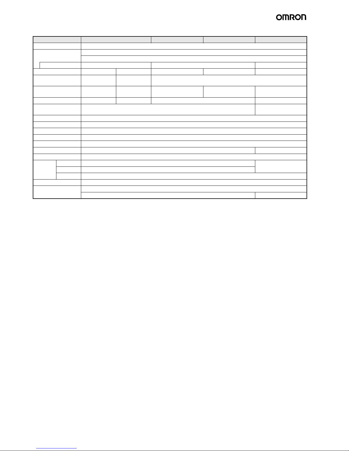
■Sensor Heads (Through-beam)
Item Model ZX-LT001 ZX-LT005 ZX-LT010 ZX-LT030
Optical system Through-beam
Light source
(wave length)
Visible-light semiconductor laser with a wavelength of 650 nm
EN class 1, FDA class II
Maximum output 0.2 mW max. 0.35 mW max. 0.2 mW max.
Measurement width 1-mm dia. 1- to 2.5-mm dia. 5 mm 10 mm 30 mm
Measurement
distance
0 to 500 mm 500 to 2,000 mm 0 to 500 mm
Minimum sensing
object
8-
µm dia.
(opaque)
8- to 50-µm dia.
(opaque)
0.05-mm dia. (opaque) 0.1-mm dia. (opaque) 0.3-mm dia. (opaque)
Resolution*1
*1.This value is obtained by converting the deviation (
±3σ) in the linear output that results when the sensor head is connected to the amplifier unit,
into the measurement width.
4
µm *2
*2.For an average count of 64. The value is 5
µm for an average count of 32.
This is the value that results when a minimum sensing object blocks the light near the center of the 1-mm measurement width.
--- 4
µm *3
*3.For an average count of 64. The value is 5
µm for an average count of 32.
12
µm *4
*4.For an average count of 64. The value is 15
µm for an average count of 32.
Temperature
characteristic
±0.2% FS/°C ±0.3% FS/°C
Ambient illumination Incandescent lamp: 10,000 l
× max. (on light-receiving side)
Ambient temperature Operating: 0 to 50
°C, Storage: −25 to 70°C (with no icing or condensation)
Ambient humidity Operating: 35% to 85% (with no condensation)
Degree of protection IEC60529, IP40
Connectio n m e t h od Connector relay (standard cable length: 500 mm)
Weight (packed state) Approx. 220 g Approx. 450 g
Cable length Extendable up to 10 m with special extension cable.
Materials Case Polyether imide Zinc die-cast
Cover Polycarbonate
Front filter Glass
Tightening torque 0.3 N
⋅m max.
Accessories Instruction sheet, Sensor Head-Amplifier Connection Cable
Optical axis adjustment seal Mounting Bracket
ZX Series (ZX-L-N) Smart Sensors (Laser T ype) 5
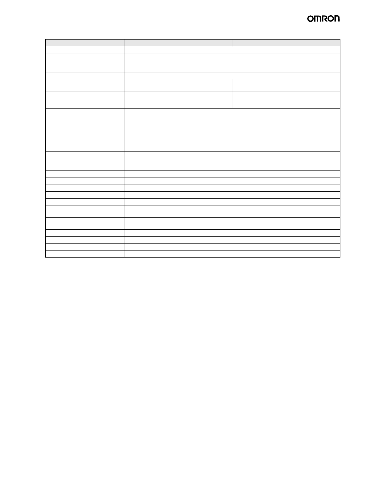
■Amplifier Units
Item Model ZX-LDA11-N ZX-LDA41-N
Measurement period 150
µs
Possible average count settings*1
*1.The response speed of the linear output is calculated as the measurement period
× (average count setting + 1) (with fixed sensitivity).
The response speed of the judgement outputs is calculated as the measurement period
× (average count setting + 1) (with fixed sensitivity).
1, 2, 4, 8, 16, 32, 64, 128, 256, 512, 1,024, 2,048, or 4,096
Temperature characteristic When connected to a Reflective Sensor Head: 0.01% FS/
°C, When connected to a Through-beam Sensor
Head: 0.1% FS/
°C
Linear output*2
*2.T he outpu t can be switched between a current output and voltage output using a switch on the bottom of the Amplifier Unit.
4 to 20 mA/FS, Max. load resistance: 300
Ω, ±4 V (± 5 V, 1 to 5 V *3), Output impedance: 100 Ω
*3.Setting is possible via the monitor focus function.
Judgement outputs
(3 outputs: HIGH/PASS/LOW)*1
NPN open-collector outputs, 30 VDC, 50 mA max.
Residual voltage: 1.2 V max.
PNP open-collector outputs, 30 VDC, 50 mA max.
Residual voltage: 2 V max.
Laser OFF input, zero reset input,
timing input, reset input
ON: Short-circuited with 0-V terminal or 1.5 V or less
OFF: Open (leakage current: 0.1 mA max.)
ON: Supply voltage short-circuited or supply voltage
within 1.5 V
OFF: Open (leakage current: 0.1 mA max.)
Functions Measurement value display, present value/set value/light lev el/resolution displa y, scaling, display re verse ,
display OFF mode, ECO mode, number of display digit changes, sample hold, peak hold, bottom hold,
peak-to-peak hold, self-peak hold, self-bottom hold, average hold, delay hold, intensity mode, zero reset,
initial reset, ON-delay timer, OFF-delay timer, one-shot timer, deviation, previous value comparison,
sensitivity adjustment, keep/clamp switch, direct threshold value setting, position teaching, 2-point
teaching, automatic teaching, hysteresis width setting, timing inputs, reset input, monitor focus, linear
output compensation, (A-B) calculations*4, (A+B) calculations*4, mutual interference*4, laser
deterioration detection, zero reset memory, zero reset display, key loc k
*4.A Calculating Unit (ZX-CAL2) is required.
Indications Operation indicators: High (orange), pass (green), low (yellow), 7-segment main display (red), 7-segment
subdisplay (yellow), laser ON (green), zero reset (green), enable (green)
Power supply voltage 12 to 24 VDC
±10%, Ripple (p-p): 10% max.
Current consumption 140 mA max. with power supply voltage of 24 VDC (with Sensor connected)
Ambient temperature Operating: 0
to 50°C, Storage: −15 to 60°C (with no icing or condensation)
Ambient humidity Operating and storage: 35% to 85% (with no condensation)
Insulation resistance 20 M
Ω min. at 500 VDC
Dielectric strength 1,000 VAC, 50/60 Hz for 1 min
Vibration resistance
(destruction)
10 to 150 Hz, 0.7-mm double amplitude 80 min each in X, Y, and Z directions
Shock resistance
(destruction)
300 m/s
2
3 times each in six directions (up/down, left/right, forward/backward)
Connection method Prewired (standard cable length: 2 m)
Weight (packed state) Approx. 350 g
Materials Case: PBT (polybutylene terephthalate), Cover: Polycarbonate
Accessories Instruction sheet
6 ZX Series (ZX-L-N) Smart Sensors (Laser Type)
■Calculating Unit
■ZX-series Communications Interface Unit
* Contact your OMRON representative for CompoWay/F communications specifications.
Item ZX-CAL2
Applicable Amplifier Units ZX-LDA11-N/41-N/ZX-EDA11/41/ZX-TDA11/41
Current consumption 12 mA max. (supplied from the Smart Sensor Amplifier Unit)
Ambient temperature Operating: 0 to 50
°C, Storage: −15 to 60°C (with no icing or condensation)
Ambient humidity Operating and storage: 35% to 85% (with no condensation)
Connectio n m e t h od Connector
Dielectric strength 1,000 VA C, 50/60 Hz for 1 min
Insulation resistance 100 M
Ω (at 500 VDC)
Vibration resistance (destructive) 10 to 150 Hz, 0.7-mm double amplitude 80 min each in X, Y, and Z directions
Shock resistance (destructive) 300 m/s
2
3 times each in six directions (up/down, left/right, forward/backward)
Materials Display: Acrylic, Case: ABS resin
Weight (packed state) Approx. 50 g
Item ZX-SF11
Current consumption 60 mA max. (supplied by the Amplifier Unit)
Applicable Amplifier Units ZX Series
Applicable A m p l i f i e r Unit versions ZX-LDA@1-N Ver. 1.000 or higher
ZX-EDA@1 Ver. 1.100 or higher
ZX-TDA@1 Ver. 1.000 or higher
Max. No. of Amplifier Units 5
Communications
functions
Communications
port
RS-232C port (9-pin D-Sub Connector)
Communications
protocol
CompoWay/F*
Baud rate 38,400 bps
Data configuration Data bits: 8, Parity: none, Start bits: 1, Stop bits: 1, Flow control: none
Indicators Power supply: green, Sensor communications: green, Sensor communications error: red, External
terminal communications: green, External terminal communications error: red
Protective circuits Reverse polarity protection
Ambient temperature Operating: 0 to 50
°C, storage: −15 to 60°C (with no icing or condensation)
Ambient humidity Operating and storage: 35% to 85% (with no condensation)
Insulation resistance 20 M
Ω min. (at 500 VDC)
Dielectric strength 1,000 VAC, 50/60 Hz for 1 min, Leakage current: 10 mA max.
Materials Case: PBT (polybutylene terephthalate), Cover: Polycarbonate
Accessories Instruction sheet, 2 clamps
ZX Series (ZX-L-N) Smart Sensors (Laser T ype) 7
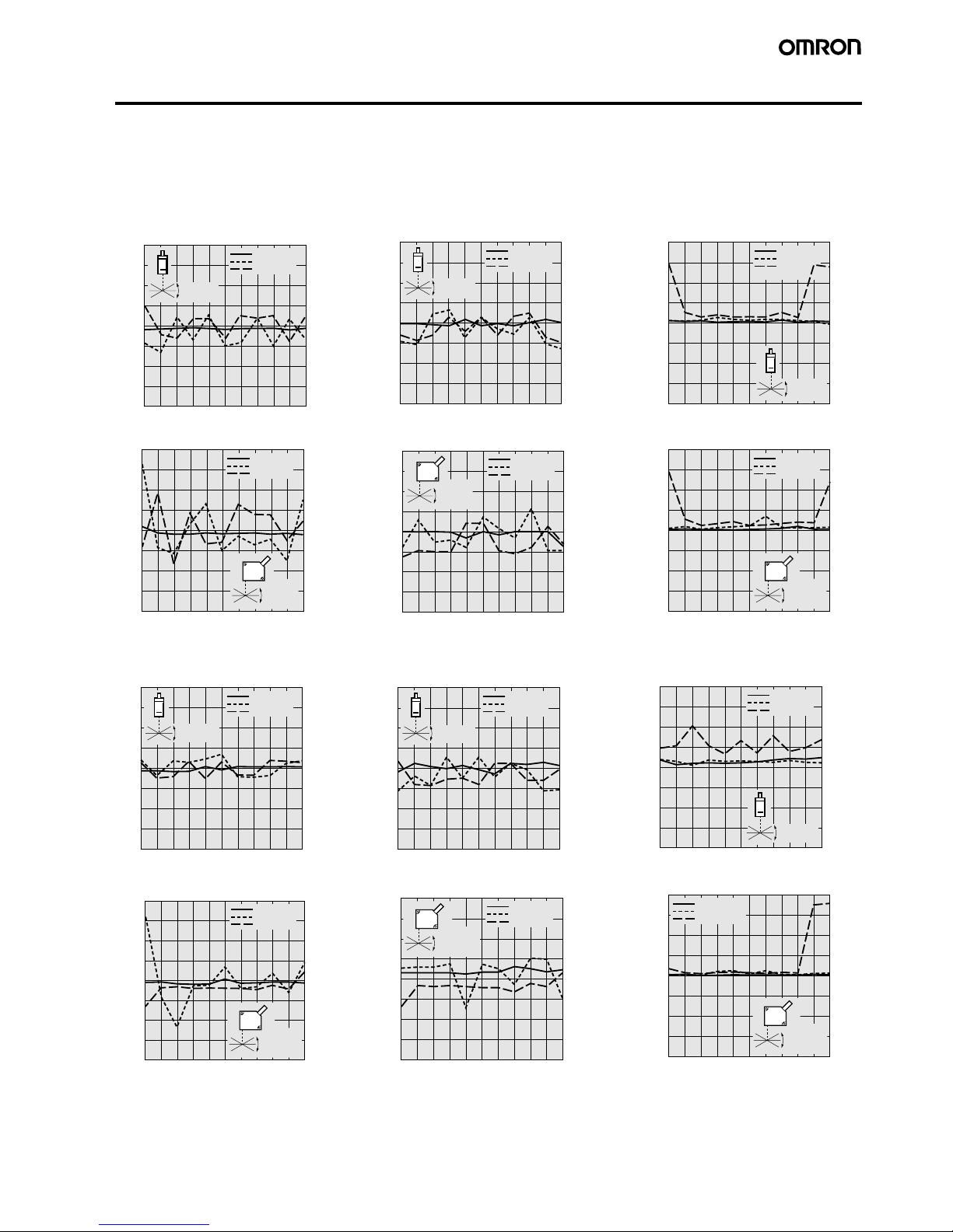
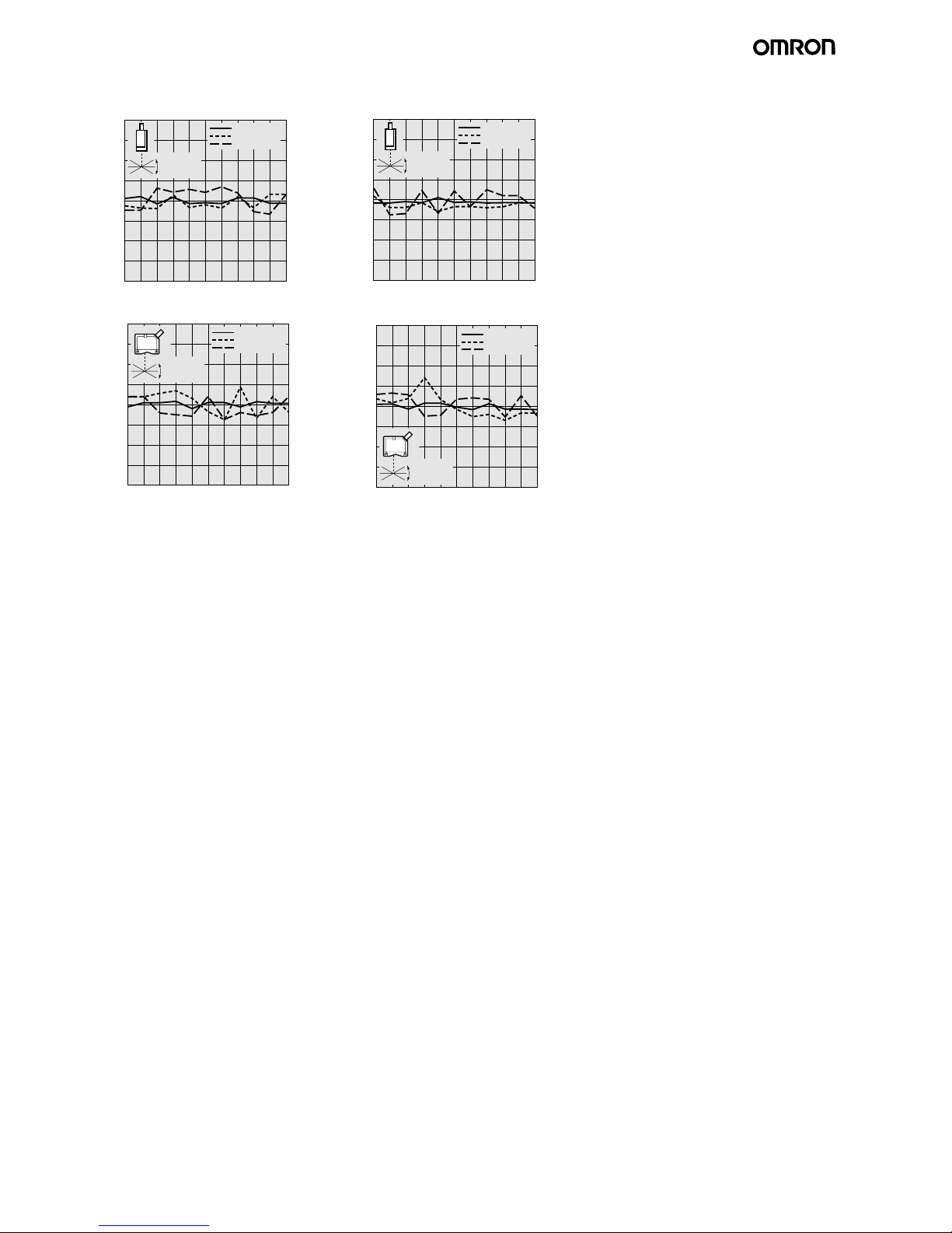
Engineering Data (Typical)
Angle Characteristic (Reflective Sensors)
The angle characteristic plots the relation between the inclination of the measurement object and the error in the linear output at the measurement point.
Note: SUS304 = Stainless steel SUS304
4
3
2
1
0
−1
−2
−3
−4
−10
−8 −6 −4 −20246810
4
3
2
1
0
−1
−2
−3
−4
−10
−8 −6 −4 −20246810
4
3
2
1
0
−1
−2
−3
−4
−10
−8 −6 −4 −20246810
4
3
2
1
0
−1
−2
−3
−4
−10
−8 −6 −4 −20246810
4
3
2
1
0
−1
−2
−3
−4
−10
−8 −6 −4 −20246810
20
15
10
5
0
−5
−10
−15
−20
−10
−8 −6 −4 −20246810
20
15
10
5
0
−5
−10
−15
−20
−10
−8 −6 −4 −20246810
4
3
2
1
0
−1
−2
−3
−4
−10
−8 −6 −4 −20246810
4
3
2
1
0
−1
−2
−3
−4
−10
−8 −6 −4 −20246810
4
3
2
1
0
−1
−2
−3
−4
−10
−8 −6 −4 −20246810
4
3
2
1
0
−1
−2
−3
−4
−10
−8 −6 −4 −20246810
20
15
10
5
0
−5
−10
−15
−20
−10
−8 −6 −4 −20246810
●ZX-LD40
Side-to-side Inclination
Front-to-back Inclination
Error (% FS)
Angle of inclination (°)
White ceramic
SUS304
Black paper
+ inclination
− inclination
Error (% FS)
Angle of inclination (°)
White ceramic
SUS304
Black
paper
+ inclination
− inclination
Error (% FS)
Angle of inclination (°)
White ceramic
SUS304
Black paper
+ inclination
− inclination
Error (% FS)
Angle of inclination (°)
White ceramic
SUS304
Black paper
+ inclination
− inclination
Error (% FS)
Angle of inclination (°)
White ceramic
SUS304
Black paper
+ inclination
− inclination
Front-to-back In cli na tion
Front-to-back Inclination
●ZX-LD100
Side-to-side Inclination
●ZX-LD300
Side-to-side Inclination
●ZX-LD40L
Side-to-side Inclination
●ZX-LD100L
Side-to-side Inclination
●ZX-LD300L
Side-to-side Inclination
Front-to-back Inclination
Error (% FS)
Angle of inclination (°)
White ceramic
SUS304
Black paper
+ inclination
− inclination
Error (% FS)
Angle of inclination (°)
White ceramic
SUS304
Black paper
+ inclination
− inclination
Error (% FS)
Angle of inclination (°)
White ceramic
SUS304
Black paper
+ inclination
− inclination
Front-to-back Inclination
Front-to-back Inclination
Error (% FS)
Angle of inclination (°)
White ceramic
SUS304
Black paper
+ inclination
− inclination
Error (% FS)
Angle of inclination (°)
White ceramic
SUS304
Black paper
+ inclination
− inclination
Error (% FS)
Angle of inclination (°)
White ce ramic
SUS304
Black paper
+ inclination
− inclination
Error (% FS)
Angle of inclination (°)
White ceramic
SUS304
Black paper
+ inclination
− inclination
8 ZX Series (ZX-L-N) Smart Sensors (Laser Type)
4
3
2
1
0
−1
−2
−3
−4
−10
−8 −6 −4 −20246810
4
3
2
1
0
−1
−2
−3
−4
−10
−8 −6 −4 −20246810
4
3
2
1
0
−1
−2
−
3
−4
−10
−8 −6 −4 −20246810
4
3
2
1
0
−1
−2
−3
−4
−10
−8 −6 −4 −20246810
White ceramic
SUS304
Black paper
− inclination
+ inclination
●ZX-LD30V
Side-to-side Inclination
Front-to-back Inclination
Front-to-back Inclination
●ZX-LD30VL
Side-to-side Inclination
Linearity error (%FS)
Linearity error (%FS)
Angle of inclination (°)
White ce ramic
SUS304
Black paper
+ inclination
− inclination
Angle of inclination (°)
White ceramic
SUS304
Black paper
+ inclination
− inclination
Linearity error (%FS)
Angle of inclination (°)
White ceramic
SUS304
Black paper
+ inclination
− inclination
Angle of inclination (°)
Linearity error (%FS)
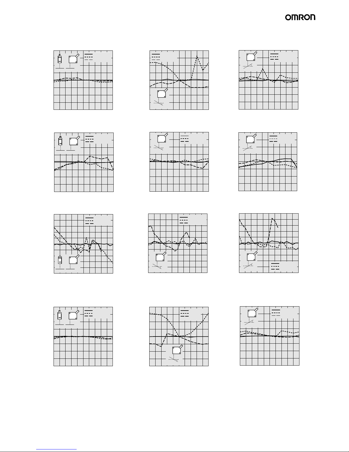
ZX Series (ZX-L-N) Smart Sensors (Laser T ype) 9
Linearity Characteristic for Different Materials (Reflective Sensors)
4
3
2
1
0
−1
−2
−3
−4
4644 48 5040 4236 38343230
4
3
2
1
0
−1
−2
−3
−4
60 124116 132 140100 10884 927668
5
4
3
2
1
0
−1
−2
−3
−4
−5
420380 460 500300 340220 260180140100
30
4
3
2
1
0
−1
−2
−3
−4
4644 48 5040 4236 383432
4
3
2
1
0
−1
−2
−3
−4
4644 48 5040 4236 38343230
4
3
2
1
0
−1
−2
−3
−4
4644 48 5040 4236 38343230
4
3
2
1
0
−1
−2
−3
−4
60
124116 132 140100 10884 927668
4
3
2
1
0
−1
−2
−3
−4
60 124116 132 140100 10884 927668
5
4
3
2
1
0
−1
−2
−3
−4
−5
420380 460 500300 340220 260180140100
5
4
3
2
1
0
−1
−2
−3
−4
−5
420380 460 500300 340220 260180140100
4
3
2
1
0
−1
−2
−3
−4
30
4644 48 5040 4236 383432
4
3
2
1
0
−1
−2
−3
−4
30
4644 48 5040 4236 383432
●ZX-LD40
0° Inclination
Error (% FS)
Distance (mm)
0° inclination
−10° Inclination Front-to-back
White ceramic
SUS304
Black paper
●ZX-LD100
0° Inclination
10
° Inclination
−10° Inclination Front-to-back
10
° Inclination
●ZX-LD300
0° Inclination
−10° Inclination Front-to-back
10
° Inclination
●ZX-LD40L
0° Inclination
−10° Inclination Front-to-back
10
° Inclination
Error (% FS)
Distance (mm)
−10° inclination
White ceramic
SUS304
Black paper
Error (% FS)
Distance (mm)
10° inclination
White ceramic
SUS304
Black paper
Error (% FS)
Distance (mm)
0° inclination
White ceramic
SUS304
Black paper
Error (% FS)
Distance (mm)
−10° inclination
White ceramic
SUS304
Black
paper
Error (% FS)
Distance (mm)
10° inclination
White ceramic
SUS304
Black paper
Error (% FS)
Distance (mm)
0° inclination
White ce ramic
SUS304
Black paper
Error (% FS)
Distance (mm)
−10° inclination
White ceramic
SUS304
Black paper
Error (% FS)
Distance (mm)
10° inclination
Error (% FS)
Distance (mm)
0° inclinat i o n
White ceramic
SUS304
Black paper
Error (% FS)
Distance (mm)
−10° inclina t i o n
White ceramic
SUS304
Black paper
Error (% FS)
Distance (mm)
10° inclination
White ce ramic
SUS304
Black paper
White ceramic
SUS304
Black paper
 Loading...