

Page 1

Cat. No. Z263-E1-01
ZX-GT Series
Smart Sensor
USER’S MANUAL
Page 2

Introduction
Thank you for purchasing the ZX-GT series.
This manual provides information regarding functions, performance and operating methods that
are required for using the ZX-GT.
When using the ZX-GT, be sure to observe the following:
• The ZX-GT must be operated by personnel knowledgeable in electrical engineering.
• To ensure correct use, please read this manual thoroughly to deepen your understanding of the
product.
• Please keep this manual in a safe place so that it can be referred to whenever necessary.
Page 3
APPRICATION CONSIDERATIONS
(Please read)
User's Manual
BEFORE USE
BASIC OPERATIONS
FUNCTION SETTINGS
COMMUNICATIONS WITH
EXTERNAL DEVICES
APPENDICES
1
2
3
4
5
Smart Sensor
Wide Laser Beam CCD Measurement Sensor
ZX-GT Series
Page 4

READ AND UNDERSTAND THIS DOCUMENT
Please read and understand this document before using the products. Please
consult your OMRON representative if you have any questions or comments.
WARRANTY
OMRON’s exclusive warranty is that the products are free from defects in materials
and workmanship for a period of one year (or other period if specified) from date of
sale by OMRON.
OMRON MAKES NO WARRANTY OR REPRESENTATION, EXPRESS OR
IMPLIED, REGARDING NON-INFRINGEMENT, MERCHANTABILITY, OR FITNESS
FOR PARTICULAR PURPOSE OF THE PRODUCTS. ANY BUYER OR USER
ACKNOWLEDGES THAT THE BUYER OR USER ALONE HAS DETERMINED
THAT THE PRODUCTS WILL SUITABLY MEET THE REQUIREMENTS OF THEIR
INTENDED USE. OMRON DISCLAIMS ALL OTHER WARRANTIES, EXPRESS OR
IMPLIED.
LIMITATIONS OF LIABILITY
OMRON SHALL NOT BE RESPONSIBLE FOR SPECIAL, INDIRECT, OR
CONSEQUENTIAL DAMAGES, LOSS OF PROFITS OR COMMERCIAL LOSS IN
ANY WAY CONNECTED WITH THE PRODUCTS, WHETHER SUCH CLAIM IS
BASED ON CONTRACT, WARRANTY, NEGLIGENCE, OR STRICT LIABILITY.
In no event shall responsibility of OMRON for any act exceed the individual price of
the product on which liability is asserted.
IN NO EVENT SHALL OMRON BE RESPONSIBLE FOR WARRANTY, REPAIR, OR
OTHER CLAIMS REGARDING THE PRODUCTS UNLESS OMRON’S ANALYSIS
CONFIRMS THAT THE PRODUCTS WERE PROPERLY HANDLED, STORED,
INSTALLED, AND MAINTAINED AND NOT SUBJECT TO CONTAMINATION,
ABUSE, MISUSE, OR INAPPROPRIATE MODIFICATION OR REPAIR.
2
ZX-GT User’s Manual
Page 5

SUITABILITY FOR USE
THE PRODUCTS CONTAINED IN THIS DOCUMENT ARE NOT SAFETY RATED.
THEY ARE NOT DESIGNED OR RATED FOR ENSURING SAFETY OF PERSONS,
AND SHOULD NOT BE RELIED UPON AS A SAFETY COMPONENT OR PROTECTIVE DEVICE FOR SUCH PURPOSES.
Please refer to separate catalogs for OMRON’s safety rated products.
OMRON shall not be responsible for conformity with any standards, codes, or
regulations that apply to the combination of products in the customer’s application or
use of the product.
At the customer’s request, OMRON will provide applicable third party certification
documents identifying ratings and limitations of use that apply to the products. This
information by itself is not sufficient for a complete determination of the suitability of
the products in combination with the end product, machine, system, or other
application or use.
The following are some examples of applications for which particular attention must
be given. This is not intended to be an exhaustive list of all possible uses of the
products, nor is it intended to imply that the uses listed may be suitable for the
products:
• Outdoor use, uses involving potential chemical contamination or electrical
interference, or conditions or uses not described in this document.
• Nuclear energy control systems, combustion systems, railroad systems, aviation
systems, medical equipment, amusement machines, vehicles, safety equipment,
and installations subject to separate industry or government regulations.
• Systems, machines, and equipment that could present a risk to life or property.
Please know and observe all prohibitions of use applicable to the products.
NEVER USE THE PRODUCTS FOR AN APPLICATION INVOLVING SERIOUS
RISK TO LIFE OR PROPERTY WITHOUT ENSURING THAT THE SYSTEM AS A
WHOLE HAS BEEN DESIGNED TO ADDRESS THE RISKS, AND THAT THE
OMRON PRODUCT IS PROPERLY RATED AND INSTALLED FOR THE
INTENDED USE WITHIN THE OVERALL EQUIPMENT OR SYSTEM.
ZX-GT User’s Manual
3
Page 6

PERFORMANCE DATA
Performance data given in this document is provided as a guide for the user in
determining suitability and does not constitute a warranty. It may represent the result
of OMRON’s test conditions, and the users must correlate it to actual application
requirements. Actual performance is subject to the OMRON Warranty and
Limitations of Liability.
CHANGE IN SPECIFICATIONS
Product specifications and accessories may be changed at any time based on
improvements and other reasons.
It is our practice to change model numbers when published ratings or features are
changed, or when significant construction changes are made. However, some
specifications of the product may be changed without any notice. When in doubt,
special model numbers may be assigned to fix or establish key specifications for
your application on your request. Please consult with your OMRON representative at
any time to confirm actual specifications of purchased products.
DIMENSIONS AND WEIGHTS
Dimensions and weights are nominal and are not to be used for manufacturing
purposes, even when tolerances are shown.
ERRORS AND OMISSIONS
The information in this document has been carefully checked and is believed to be
accurate; however, no responsibility is assumed for clerical, typographical, or
proofreading errors, or omissions.
PROGRAMMABLE PRODUCTS
OMRON shall not be responsible for the user’s programming of a programmable
product, or any consequence thereof.
COPYRIGHT AND COPY PERMISSION
This document shall not be copied for sales or promotions without permission.
This document is protected by copyright and is intended solely for use in conjunction
with the product. Please notify us before copying or reproducing this document in
any manner, for any other purpose. If copying or transmitting this document to
another, please copy or transmit it in its entirety.
4
ZX-GT User’s Manual
Page 7
Meanings of Signal Words
The following signal words are used in this manual.
Indicates a potentially hazardous situation which, if not avoided, will
result in minor or moderate injury, or may result in serious injury or
death. Additionally there may be significant property damage.
Indicates a potentially hazardous situation which, if not avoided,
may result in minor or moderate injury or in property damage.
Meanings of Alert Symbols
The following alert symbols are used in this manual.
Indicates general prohibitions for which there is no specific symbol.
Indicates the possibility of laser radiation.
Indicates prohibition when there is a risk of minor injury from electrical
shock or other source if the product is disassembled.
ZX-GT User’s Manual
5
Page 8
This product is not designed or rated for ensuring safety of persons.
Do not use it for such purposes.
Never look into the laser beam. Doing so continuously will result in
visual impairment.
Do not attempt to dismantle, pressurize, or incinerate the product. Doing
so may cause the laser beam to leak, resulting in the danger of visual
impairment.
6
ZX-GT User’s Manual
Page 9
Precautions for Safe Use
The following points are important to ensure safety, so make sure that they are strictly
observed.
1. Installation Environment
• Do not use the product in environments where it can be exposed to inflammable/
explosive gas.
• To secure the safety of operation and maintenance, do not install the product close to
high-voltage devices and power devices.
• Install the product in such a way that its ventilation holes are not blocked. (excluding
the connecting surface when the products are connected to each other)
• Tighten the mounting screws with a torque specified in this manual.
2. Power Supply and Wiring
• The voltage and AC power supply must be within the rated range (24 VDC +10%, -15%).
• Reverse connection of the power supply is not allowed. Connection to an AC power
supply is also not allowed.
• The output load should not be short-circuited.
• Use the power supply within the rated load.
• High-voltage lines and power lines must be wired separately from this product. Wiring
them together or placing them in the same duct may cause induction, resulting in
malfunction or damage.
• Use the product within the power supply voltage specified by this manual.
• Use a DC power supply with safety measures against high-voltage spikes (safety extra
low-voltage circuits on the secondary side).
• Use only combinations of the Sensor and Controller specified in this manual.
Controller Specifications p.133
• When connecting Controllers to each other, use only combinations of the Controllers
specified in this manual.
Connecting Controllers to each other p.37
• Connect the exclusive device (Sensor). The product might break down or malfunction
if you use a part not included in the exclusive products.
3. Other
• Do not disassemble, repair, modify, pressurize, or incinerate the product.
• Dispose of this product as industrial waste.
• Should you notice any abnormalities, immediately stop use, turn OFF the power
supply, and contact your OMRON representative.
ZX-GT User’s Manual
7
Page 10
Precautions for Correct Use
Observe the following precautions to prevent failure to operate, malfunctions, or
undesirable effects on product performance.
1. Installation Site
Do not install this product in locations subjected to the following conditions:
• Ambient temperature outside the rating
• Rapid temperature fluctuations (causing condensation)
• Relative humidity outside the range of 35 to 85%
• Direct vibration or shock
• Reflection of intense light (such as other laser beams or electric arc-welding machines)
• Direct sunlight or near heaters
• Strong magnetic or electric field
Also, do not install this product in locations subjected to the following conditions due to
the degree of protection specified in the ratings:
• Presence of corrosive or flammable gases
• Presence of dust, salt, or iron particles
• Water, oil, or chemical fumes or spray
2. Power Supply and Wiring
• When using a commercially available switching regulator, make sure that the FG
terminal is grounded.
• If surge currents are present in the power lines, connect surge absorbers that suit the
operating environment.
• Before turning ON the power after the product is connected, make sure that the power
supply voltage is correct, there are no incorrect connections (e.g. load short-circuit), and
the load current is appropriate. Incorrect wiring may result in breakdown of the product.
• Before connecting/disconnecting devices, make sure that the Sensor/Controller is
turned OFF. The Sensor or Controller may break down if it is connected/disconnected
while the power is ON.
• Use the extension cable sold separately for extending the cable between the Sensor
(receiver) and the Controller.
p.20
3. Warming Up
After turning the power supply ON, allow the product to stand for at least 10 minutes
before use. The circuits are still unstable just after the power supply is turned ON, so
measurement values may fluctuate gradually.
4. Maintenance and Inspection
Do not use thinner, benzene, acetone or kerosene to clean the Sensor and Controller. If
large dust particles adhere to the filter on the front of the Sensor, use a blower brush
(used to clean camera lenses) to blow them off. Do not use breath from your mouth to
blow the dust off. To remove dust particles from the Sensor, wipe gently with a soft cloth
(for cleaning lenses) moistened with a small amount of alcohol. Do not use excessive
force to wipe off dust particles. Scratches to the filter might cause error.
8
ZX-GT User’s Manual
Page 11

Editor’s Note
■ Meaning of Symbols
Menu items that are displayed on the Controller’s LCD screen, and windows, dialog boxes
and other GUI elements displayed on the PC are indicated enclosed by brackets “[ ]”.
■ Visual Aids
Important
Indicates points that are important to achieve the full product performance,
such as operational precautions.
Note
Indicates application procedures.
Indicates pages where related information can be found.
ZX-GT User’s Manual
9
Page 12

MEMO
10
ZX-GT User’s Manual
Page 13

CONTENTS
Operation Step Guide . . . . . . . . . . . . . . . . . . . . . . . . . 16
1.BEFORE USE
ZX-GT Series . . . . . . . . . . . . . . . . . . . . . . . . . . . . . . . . 20
System Configuration . . . . . . . . . . . . . . . . . . . . . . . . . . . . . 20
Part Names and Functions . . . . . . . . . . . . . . . . . . . . . . . . . 21
Mounting and Connecting Devices . . . . . . . . . . . . . . 25
Mounting the Sensor . . . . . . . . . . . . . . . . . . . . . . . . . . . . . 25
Mounting the Controller . . . . . . . . . . . . . . . . . . . . . . . . . . . 27
Connecting Devices . . . . . . . . . . . . . . . . . . . . . . . . . . . . . . 28
Connecting Controllers to Each Other . . . . . . . . . . . . . . . . 37
Connecting Interface Units . . . . . . . . . . . . . . . . . . . . . . . . . 38
Initializing Controller Settings . . . . . . . . . . . . . . . . . . 39
2.BASIC OPERATIONS
Setting Measurement Conditions - FUN Mode . . . . . 42
Adjusting the Optical Axis and Registering the Standard
Received Light Intensity . . . . . . . . . . . . . . . . . . . . . . . . . . . 42
Selecting the Measurement Mode . . . . . . . . . . . . . . . . . . . 44
Setting Thresholds - T Mode . . . . . . . . . . . . . . . . . . . 45
Functions and Operations during Operation
- RUN Mode . . . . . . . . . . . . . . . . . . . . . . . . . . . . . . . . . 46
Switching the Measured Value Display . . . . . . . . . . . . . . . 46
Executing and Canceling a Zero Reset . . . . . . . . . . . . . . . 47
1
CONTENTS
ZX-GT User’s Manual
11
Page 14

3.FUNCTION SETTINGS
Settings Matched to Specific Measurement
Requirements . . . . . . . . . . . . . . . . . . . . . . . . . . . . . . . . 50
Specific Measurement Requirement and Measurement
Mode Used . . . . . . . . . . . . . . . . . . . . . . . . . . . . . . . . . . . . . 50
Explanation of Measurement Modes . . . . . . . . . . . . . . . . . 52
Adjusting Detection Conditions . . . . . . . . . . . . . . . . . 61
Measurement Cycle . . . . . . . . . . . . . . . . . . . . . . . . . . . . . . 61
Number of Samples to Average . . . . . . . . . . . . . . . . . . . . . 62
Binary Level . . . . . . . . . . . . . . . . . . . . . . . . . . . . . . . . . . . . 63
Edge Filter . . . . . . . . . . . . . . . . . . . . . . . . . . . . . . . . . . . . . 64
Setting Output Conditions . . . . . . . . . . . . . . . . . . . . . 65
Judgment output timing (timer) . . . . . . . . . . . . . . . . . . . . . . 65
Hysteresis . . . . . . . . . . . . . . . . . . . . . . . . . . . . . . . . . . . . . . 67
Analog Output Conditions . . . . . . . . . . . . . . . . . . . . . . . . . . 68
Setting Hold Functions . . . . . . . . . . . . . . . . . . . . . . . . 73
Hold . . . . . . . . . . . . . . . . . . . . . . . . . . . . . . . . . . . . . . . . . . 73
Delay Hold . . . . . . . . . . . . . . . . . . . . . . . . . . . . . . . . . . . . . 75
Changing Display Conditions . . . . . . . . . . . . . . . . . . . 77
Reversing the Display . . . . . . . . . . . . . . . . . . . . . . . . . . . . . 77
Changing the Number of Display Digits . . . . . . . . . . . . . . . 78
Adjusting the Display Brightness (ECO mode) . . . . . . . . . . 79
Setting Communication Conditions . . . . . . . . . . . . . . 80
RS-232C Communications Specifications . . . . . . . . . . . . . 80
Setting the Binary Output Cycle . . . . . . . . . . . . . . . . . . . . . 81
Special Functions . . . . . . . . . . . . . . . . . . . . . . . . . . . . 82
Zero Reset Memory . . . . . . . . . . . . . . . . . . . . . . . . . . . . . . 82
Display during a Zero Reset . . . . . . . . . . . . . . . . . . . . . . . . 83
Key Lock . . . . . . . . . . . . . . . . . . . . . . . . . . . . . . . . . . . . . . . 84
Switching Banks . . . . . . . . . . . . . . . . . . . . . . . . . . . . . . . . . 85
Displaying the System Version . . . . . . . . . . . . . . . . . . . . . . 87
12
ZX-GT User’s Manual
Page 15

4.COMMUNICATIONS WITH EXTERNAL
DEVICES
Output Data List . . . . . . . . . . . . . . . . . . . . . . . . . . . . . . 90
Communications Using the Controller I/O Cable . . . 91
Using the Controller I/O Cable . . . . . . . . . . . . . . . . . . . . . . 91
Binary Output . . . . . . . . . . . . . . . . . . . . . . . . . . . . . . . . 93
Assignments and Functions of Output Signal Wires . . . . . 93
Output Format . . . . . . . . . . . . . . . . . . . . . . . . . . . . . . . . . . 94
I/O Timing Charts . . . . . . . . . . . . . . . . . . . . . . . . . . . . . 95
RS-232C . . . . . . . . . . . . . . . . . . . . . . . . . . . . . . . . . . . 100
Communications on the RS-232C Interface . . . . . . . . . . . 100
Connecting External Devices . . . . . . . . . . . . . . . . . . . . . . 101
About Communications Commands . . . . . . . . . . . . . . . . . 102
Setting Acquisition/Change Commands . . . . . . . . . . . . . . 107
Measurement Control/Measured Value Acquisition
Commands . . . . . . . . . . . . . . . . . . . . . . . . . . . . . . . . . . . . 123
Bank Control Command . . . . . . . . . . . . . . . . . . . . . . . . . . 127
Utility Command . . . . . . . . . . . . . . . . . . . . . . . . . . . . . . . . 128
CONTENTS
5.APPENDICES
Specifications and External Dimensions . . . . . . . . 130
Sensor . . . . . . . . . . . . . . . . . . . . . . . . . . . . . . . . . . . . . . . 130
Controller . . . . . . . . . . . . . . . . . . . . . . . . . . . . . . . . . . . . . 133
Calculating Unit . . . . . . . . . . . . . . . . . . . . . . . . . . . . . . . . 135
Interface Unit . . . . . . . . . . . . . . . . . . . . . . . . . . . . . . . . . . 136
Extension Cable . . . . . . . . . . . . . . . . . . . . . . . . . . . . . . . . 138
Error Messages and Corrective Actions . . . . . . . . . 140
Setup Errors . . . . . . . . . . . . . . . . . . . . . . . . . . . . . . . . . . 140
Measurement Errors . . . . . . . . . . . . . . . . . . . . . . . . . . . . 140
Standard Received Light Intensity Registration Errors . . . 141
Default Values . . . . . . . . . . . . . . . . . . . . . . . . . . . . . . 142
Basic Knowledge for Operation . . . . . . . . . . . . . . . . 143
ZX-GT User’s Manual
13
Page 16

Reading Displays . . . . . . . . . . . . . . . . . . . . . . . . . . . . . . . 143
List of Key Operations . . . . . . . . . . . . . . . . . . . . . . . . . . . 143
Laser Safety . . . . . . . . . . . . . . . . . . . . . . . . . . . . . . . . 144
Label Replacement . . . . . . . . . . . . . . . . . . . . . . . . . . . . . . 144
Requirements from Regulations and
Standards . . . . . . . . . . . . . . . . . . . . . . . . . . . . . . . . . . 146
Summary of Requirements to Manufactures . . . . . . . . . . 146
Summary of Requirements to User . . . . . . . . . . . . . . . . . 150
Definitions of Laser Classification . . . . . . . . . . . . . . . . . . . 153
Compliance with EC Directives . . . . . . . . . . . . . . . . 154
Quick Reference for Displays . . . . . . . . . . . . . . . . . . 156
INDEX . . . . . . . . . . . . . . . . . . . . . . . . . . . . . . . . . . . . . 161
Revision History . . . . . . . . . . . . . . . . . . . . . . . . . . . . 164
14
ZX-GT User’s Manual
Page 17

MEMO
CONTENTS
ZX-GT User’s Manual
15
Page 18
Operation Step Guide
Basic Operation Procedure
Mounting and Connections
Mounting the Sensor
Mounting the Controller
Connecting Devices
Preparations for Measurement (FUN)
Adjusting the Optical Axis and Registering the
Standard Received Light Intensity
Selecting the Measurement Mode
Setting Thresholds (T)
Start of Operation (RUN)
Zero Reset
Communications with External Devices
I/O Cable
p.25
p.27
p.28
p.42
p.44
p.45
p.47
p.91
16
Operation Step Guide
Binary Output
RS-232C
p.93
p.100
ZX-GT User’s Manual
Page 19
To Improve Controller Performance
Ignoring Rapid Changes in Measured Values
Adjusting the Number of Samples to Average
Adjusting the Detection Sensitivity
Adjusting the Binary Level
p.62
p.63
(If required)
Adjusting the Edge Filter
Stabilizing Judgment Output
Changing/Adjusting the Timing of Judgment Outputs
Changing the Output Time
Adjusting Hysteresis
Setting the Delay Time
Returning Controller Settings to Their Defaults
Speeding the Measurement Cycle Up
Setting Hold Functions
Reversing the Controller Display
Changing the Number of Controller Display Digits
Operating in the ECO (power-saving) Mode
Holding the Zero Reset Value
p.64
p.65
p.65
p.67
p.75
p.39
p.61
p.73
p.77
p.78
p.79
p.82
Offsetting the Zero Reset Value
Key Lock Function
Switching Banks
ZX-GT User’s Manual
p.83
p.84
p.85
Operation Step Guide
17
Page 20

MEMO
18
Operation Step Guide
ZX-GT User’s Manual
Page 21

BEFORE USE
ZX-GT Series 20
System Configuration 20
Part Names and Functions 21
Mounting and Connecting Devices 25
Mounting the Sensor 25
Mounting the Controller 27
Connecting Devices 28
Connecting Controllers to Each Other 37
Connecting Interface Units 38
Initializing Controller Settings 39
1
BEFORE USE
Page 22
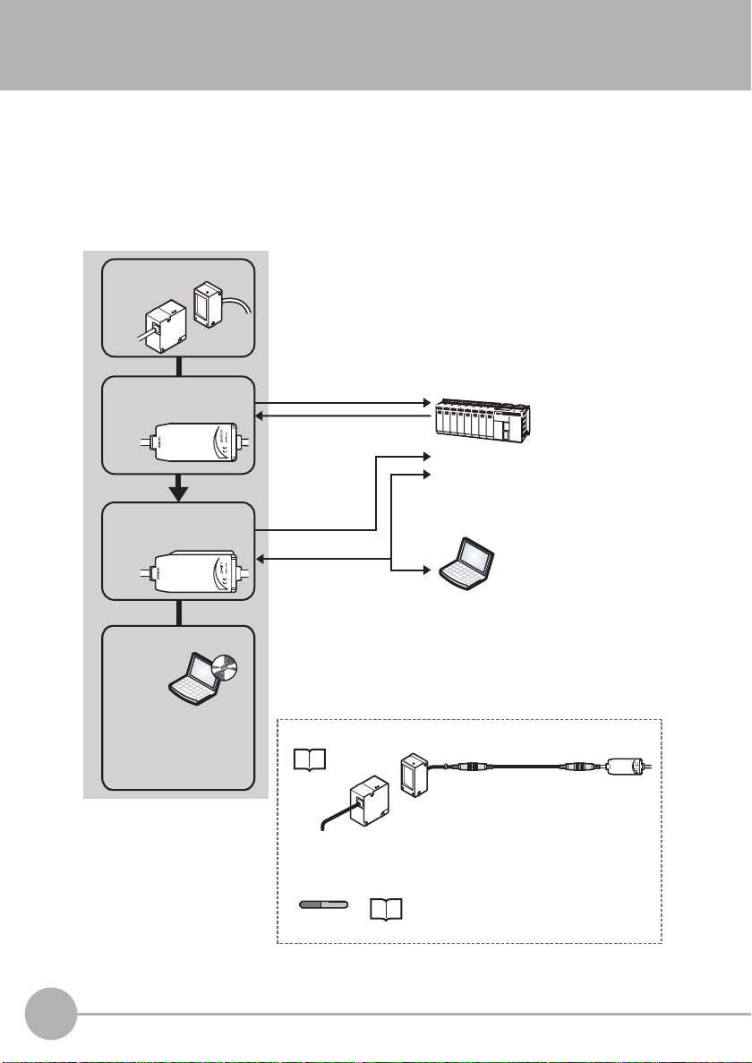
ZX-GT Series
The ZX-GT Series Smart Sensors are a length measurement sensor using a CCD device.
Position, dimensions, and other information can be stably measured by a line beam
comprising a visible semiconductor laser and an optical scale on the CCD line sensor.
System Configuration
Sensor
ZX-GT28___
Controller
ZX-GTC__
Interface
Unit
ZX-GIF__
SmartMonitor GT
ZX-GSW11
Exclusive PC software
allows complex setups and
verification of measured
values to be performed
with ease.
Analog outputs/judgment outputs
Control input
Binary output
RS-232C
PLC
Measured values and judgments can be
output. Also, the Controller can be controlled
(e.g. switching of measurement conditions
and input of triggers).
PC
Commands can be used to input triggers
and acquire measurement results. Also, the
Controller can be controlled from a PC (e.g.
changing of setup data).
Options
• Receiver-Controller Extension Cable
p.29
Extension cable:
1 m, 2 m, 5 m, 8 m, 20 m
ZX-XGC__A (standard cable)
ZX-XGC__R (flexible cable)
• Calculating Unit
ZX-CAL2
•
Connecting Controllers to Each Other p.37
• Calculation of measurement results p.59
20
ZX-GT Series
ZX-GT User’s Manual
Page 23
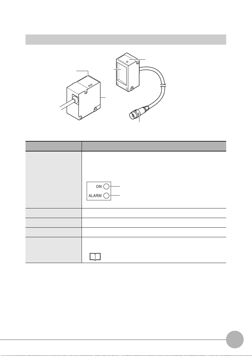
Part Names and Functions
Sensor
Receiver
Emitter
(1)
Name Function
(1) Laser indicators These are laser beam warning indicators. When the laser is being
emitted, the "laser ON indicator (ON, green)" turns ON, and when
the laser has deteriorated, the "laser deterioration alarm indicator
(ALARM, red)" turns ON.
(3)
(2)
Laser ON indicator
Laser deterioration alarm indicator
(5)
(4)
1
BEFORE USE
(2) Laser emitter This emits the laser for measurement.
(3) Laser receiver This receives the laser light emitted from the laser emitter.
(4) Connector This is the connector for connecting to the Controller.
(5) Optical axis setting
indicator
ZX-GT User’s Manual
This indicator turns ON when the laser's optical axis is aligned in
the optical axis adjustment mode.
Optical axis mode p.42
ZX-GT Series
21
Page 24
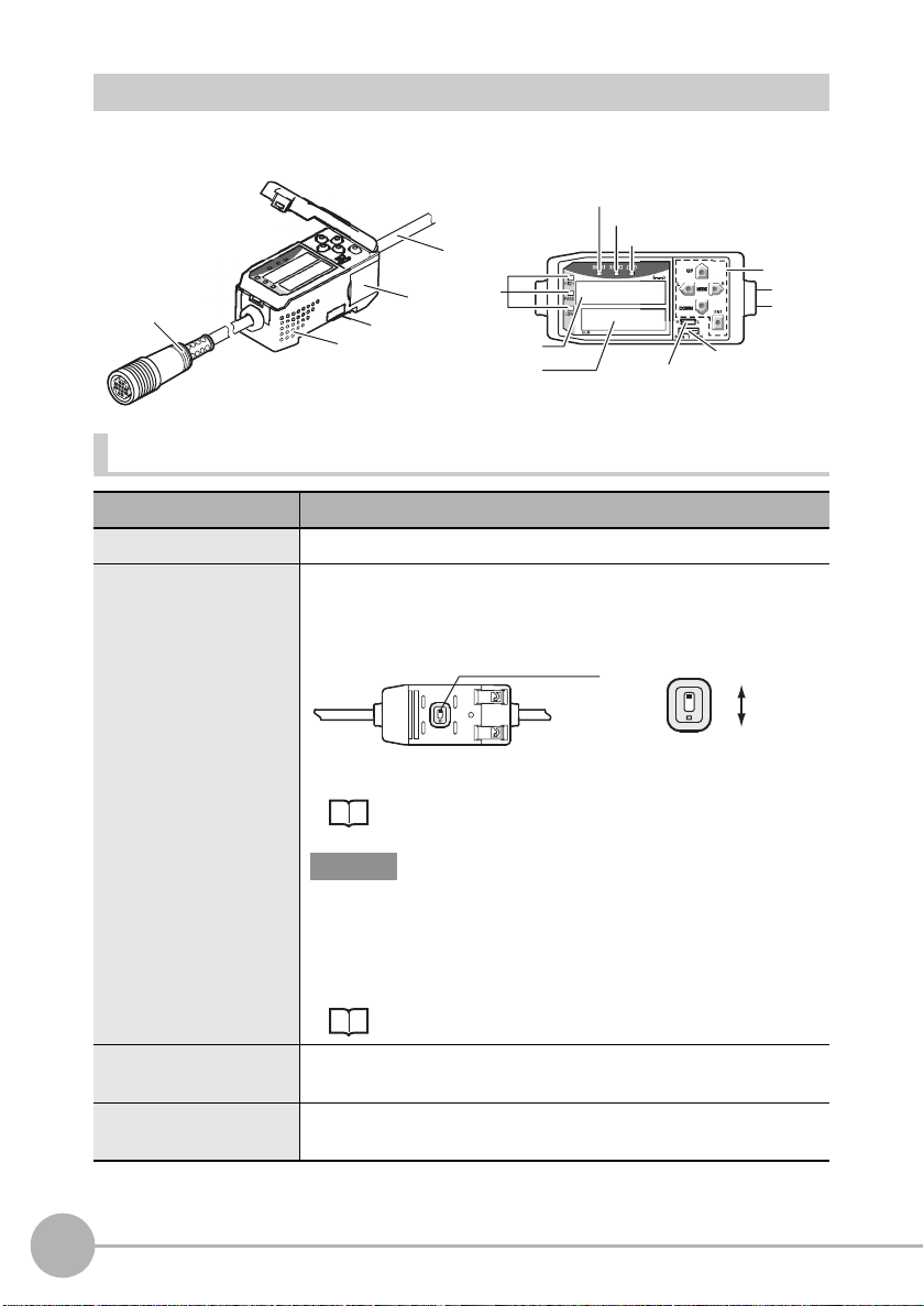
Controller
(1)
(2)
(3)
(4)
(5)
(6)
e
es
Connector Display and Operation Panel
(1)
(2)
V
ntilation hol
(4)
(3)
(7)
(9)
(8)
Connectors
Name Function
(1) Input cable This is for connecting the Sensor receiver.
(2) Voltage/Current
switch (on rear side)
(3) Controller connector This connector is for connecting Calculating and Interface Units.
(4) Output cable The output cable connects the Controller to the power supply and
This switch is for selecting voltage output or current output as the
analog output.
(default value: voltage output)
Voltage/Current switch
Output scaling settings are also required when switching the output.
Voltage output
Current output
p.68
Important
Before operating this switch, make sure that the Controller is turned
OFF. Make sure that the load connected to "analog output wire (coaxial) - analog GND wire" satisfies the rating of the set state
(voltage or current output) before turning the Controller ON.
Otherwise, the Controller may be damaged.
Rating of Connected Loads (I/O Circuit Diagrams) p.33
(total 2 connectors, one on each side)
external devices, such as timing sensors or PLCs.
22
ZX-GT Series
ZX-GT User’s Manual
Page 25
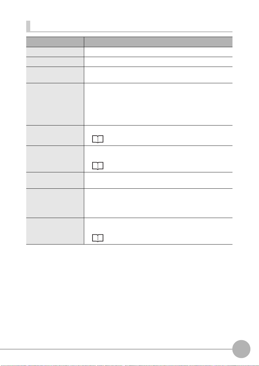
Display and operation panel
Name Function
(1) Bank 1 indicator This indicator turns ON when bank 1 is selected.
(2) Bank 2 indicator This indicator turns ON when bank 2 is selected.
(3) Zero reset
indicator
(4) Judgment output
indicator
(5) Main display
indicator
(6) Sub-display
indicator
(7) Threshold
switch
(8) Mode
switch
(9) Control keys Use the Control Keys to set the measurement conditions and
This indicator turns ON when the zero reset function is enabled.
HIGH LED : This indicator lights when "the HIGH threshold <
the measured value."
PASS LED : This indicator lights when "the LOW threshold ≤
the measured value ≤ the HIGH threshold."
LOW LED : This indicator lights when "the measured value <
the LOW threshold value."
The main display shows measured values and function names.
Reading Displays p.143
The sub-display shows additional information and function settings
for measurements.
Reading Displays p.143
The threshold switch selects whether to set (or display) the HIGH
or LOW threshold.
The mode switch selects the operation mode.
FUN : Select this mode when setting measurement conditions.
T : Select this mode when setting thresholds.
RUN : Select this mode when performing measurement.
switch the display.
List of Key Operations p.143
1
BEFORE USE
ZX-GT User’s Manual
ZX-GT Series
23
Page 26
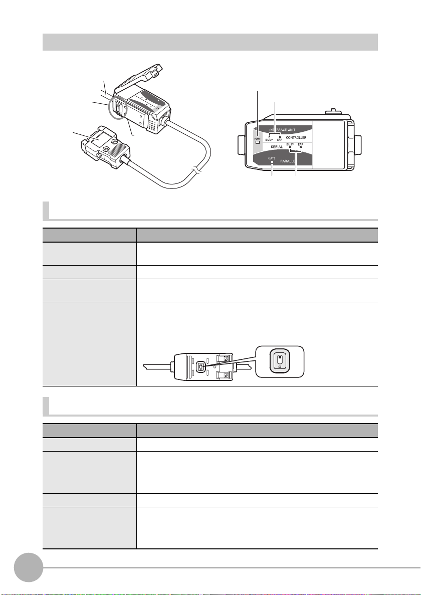
Interface Unit
Connector Display
(3)
(2)
(1)
(2)
(1)
(4)
(3)
(4)
Connector
Name Function
(1) RS-232C connector The RS-232C connector is for connecting the Controller to external
(2) Controller connector This connector is for connecting the ZX-GTC Controllers.
(3) Binary output cable This cable connects external devices such as a PLC so that
(4) Rear switch This switch is not used during measurement. Be sure to leave this
devices, such as a PC or a PLC.
measurement data is output in binary.
switch at its default setting (position in figure below). If this switch
setting is changed, the communications functions will be changed
and the Controller will not operate correctly.
Display
Name Function
(1) Power ON indicator The power ON indicator lights while the power is ON.
(2) Controller
(3)
(4) RS-232C
24
ZX-GT Series
communications
indicator
Binary output indicator
communications
indicator
BUSY: This indicator lights when communications commands are
being issued to the Controller.
ERR : This indicator lights if an error occurs during
communications with the Controller.
This indicator lights during binary output.
BUSY: This indicator lights when RS-232C communications is in
progress.
ERR : This indicator lights if an error occurs during RS-232C
communications.
ZX-GT User’s Manual
Page 27
Mounting and Connecting Devices
Mounting the Sensor
Never look into the laser beam. Doing so continuously will result in
visual impairment.
Do not attempt to dismantle, pressurize, or incinerate the product. Doing
so may cause the laser beam to leak, resulting in the danger of visual
impairment.
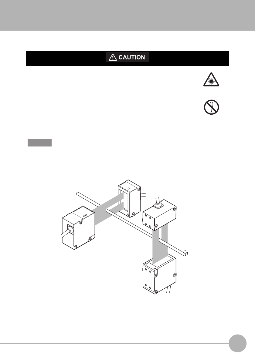
Important
If a measurement target has a shiny surface, reflected light might adversely influence adjacent
Sensors. Mount the Sensor so that it is not influenced by reflected light.
Example: XY cross measurement
Place the Sensors so that their optical axes do not overlap each other.
1
BEFORE USE
ZX-GT User’s Manual
X
Y
Mounting and Connecting Devices
25
Page 28
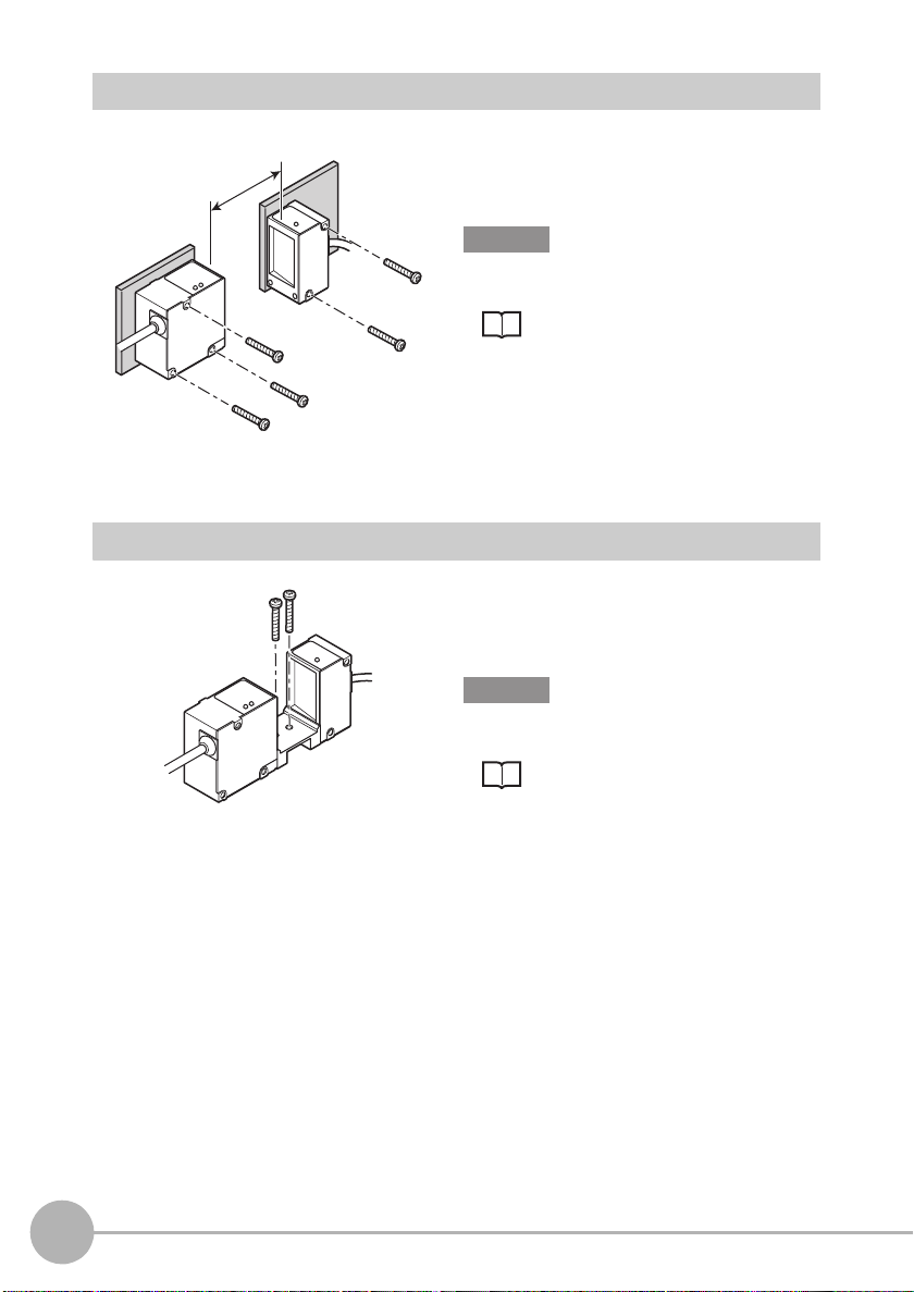
Separate Type (Emitter and Receiver)
Fix the Sensor onto the mounting base with
M4 screws.
0 to 500 (mm)
Tightening torque: 1.2 N•m
Important
For details on the positions of screw holes, check
the external dimensions in "5 APPENDICES."
Integrated Type
Fix the Sensor onto the mounting base with
M3 screws.
Tightening torque: 0.5 N•m
Important
For details on the positions of screw holes, check
the external dimensions in "5 APPENDICES."
• External dimensions p.131
• Adjusting the Optical Axis p.42
External dimensions p.132
26
Mounting and Connecting Devices
ZX-GT User’s Manual
Page 29
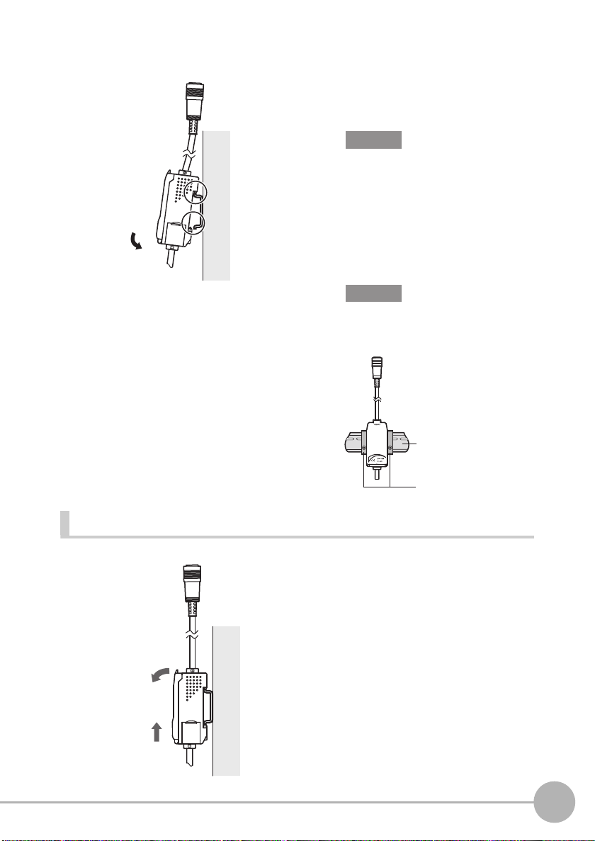
Mounting the Controller
1
1 Hook the connector end of the
Controller onto the DIN track.
Important
Always hook the connector end of the
Controller onto the DIN track first. Mounting
strength may decrease if the I/O cable end
is hooked onto the DIN track first.
1
BEFORE USE
Removal
2
2
2 Push the Controller down onto
the DIN track until the hook on the
I/O cable side is locked.
Important
After mounting the Controller on the DIN
track, attach the end plates (sold
separately) on both sides of the Controller.
DIN track (sold separately)
PFP-100N (1 m)
PFP-50N (0.5 m)
PFP-100N2 (1 m)
End plate
1 Push the Controller up towards
the connector side.
2 Lift up the Controller from the
connector end, and remove it
from the DIN track.
1
ZX-GT User’s Manual
Mounting and Connecting Devices
27
Page 30
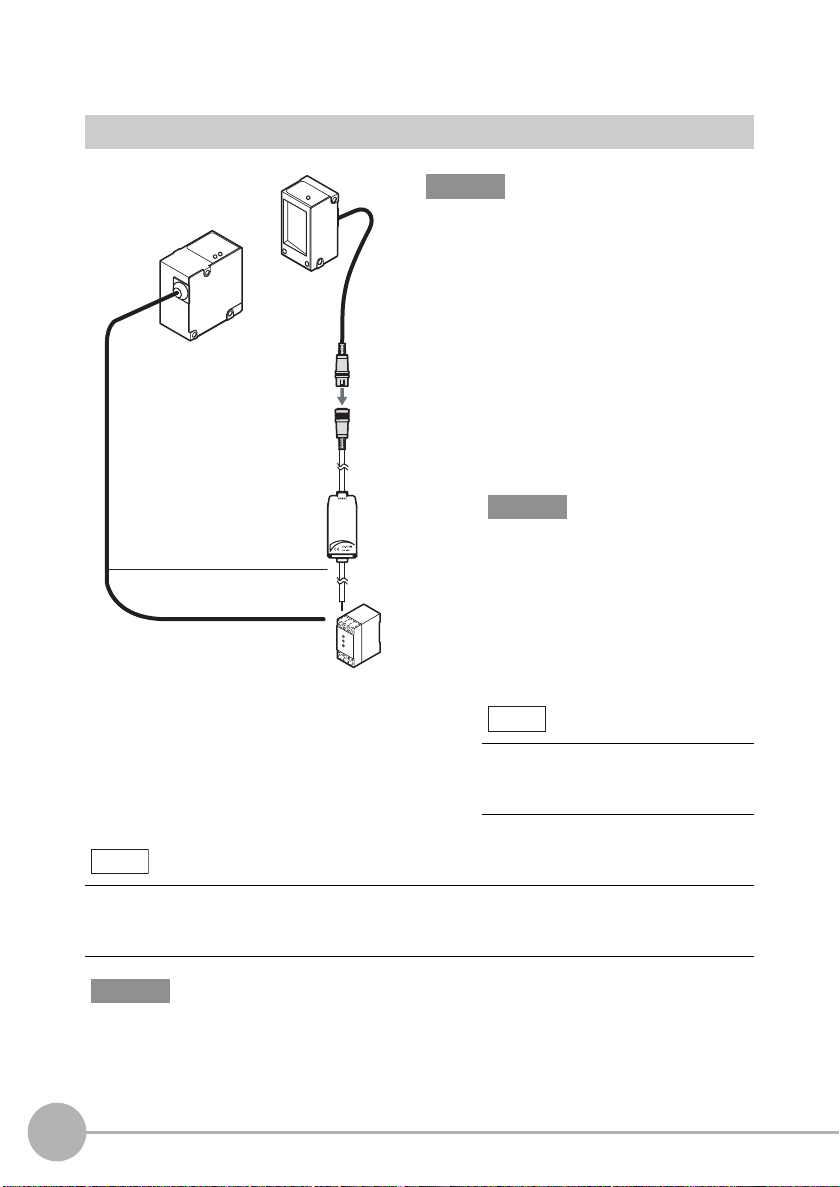
Connecting Devices
3
Connecting Devices in the Basic Configuration
Important
Before connecting/disconnecting the Sensor, make
sure that the Controller is turned OFF. The
Controller may break down if the Sensor is
connected or disconnected while the power is ON.
1 Insert the receiver connector into
the Controller connector.
1
2
3
Note
When the measurement cycle has been changed to the high-speed mode (FAST), wiring of
the sync wires is not required. Note, however, that the Controller becomes more susceptible
to the influence of ambient light in this case.
2 Connect the Controller and
Sensor sync wires.
Controller sync output wire : yellow
Emitter sync input wire : red
Important
The Controller's default mode is the
standard mode. Measurement is not
possible without the sync wires connected.
3
Connect the power wire (brown)
and the GND wire (blue) of the
emitter and the Controller I/O cable.
Note
The following power supply is
recommended:
• S8VS-03024 (24 VDC, 1.3 A)
Important
Do not mount the Controller in such a way that a load is steadily applied on the connector, for
example, with tension applied to the cables.
28
Mounting and Connecting Devices
ZX-GT User’s Manual
Page 31

To extend the connection between the receiver and the Controller
The cable connection between the receiver and the Controller can be extended by up to
30 meters using the extension cable (sold separately). The emitter side can be extended
by up to 30 meters by connecting via the terminal block, for example.
Within 30 m
Cable
Cable
Within
30 m
*1: Up to two extension cables can be connected. However, be sure to limit the total extension cable length
2 m
Connect via terminal block Connect via terminal block
Other than
sync wire
between the receiver and the Controller to 30 meters (including the receiver cable).
2 m
(The sync wire can be extended by up to 30 meters between
the emitter and the Controller.)
Extension cable
: 1 m, 2 m, 5 m, 8 m, 20 m
ZX-XGC__A (standard cable)
ZX-XGC__R (flexible cable)
Sync wire
Within 26 m
(*1)
Cable
0.2 m
Cable
2 m
Other than
sync wire
Wiring the Sensor (emitter)
Wiring diagram
Brown
Blue
Orange
Red
Names and functions
Cable color
Brown Power supply
Blue GND (0V) This is the power supply 0 V terminal.
Orange
Red Laser OFF
Name Function
This is the power supply terminal. Connect the 24 VDC power
(24 VDC)
supply to this terminal.
When using a PNP type Controller, the power supply terminal is
also the common terminal for all I/O.
When using an NPN type Controller, the power supply terminal is
also the common terminal for all I/O.
Laser deterioration
alarm output
This output turns ON when the semiconductor laser deteriorates.
Replace the Sensor when this output turns ON.
Laser emission stops when this output turns ON.
input/sync
input
Synchronized operation is available with this wire connected to the
Controller's sync output, and the influence of ambient light can be reduced.
Laser output can also be turned OFF with this input short-circuited to 0
V (24 V in the case of a PNP type Controller) in this connection state.
Power supply (24 VDC)
GND (0 V)
Laser deterioration alarm output
Laser OFF input/sync input
Within
10 m
1
BEFORE USE
ZX-GT User’s Manual
Mounting and Connecting Devices
29
Page 32

Wiring the Controller
Wiring diagram
Brown
Blue
White
Green
Gray
Co-axial (black)
Co-axial (shield)
Pink
Orange
Purple
Red
Yellow
Light blue
Black
Power supply (24 V)
GND (0 V)
HIGH
PASS
LOW
Analog output
Analog GND
Bank switching input
Zero reset input
Timing input
Reset input
Sync output
Unused
Unused
4 output
terminals
4 input
terminals
Important
• Use a stabilized power supply separate from other devices and power systems for the
Controller, particularly when high resolution is required.
Recommended power supply p.28
• Wire the Controller correctly. Otherwise, the Controller may be damaged. (Pay particular
attention to prevent contact between the analog output and other wires.)
• Use the blue wire (GND (0 V)) for the power supply, and the shielded wire sheath (analog
GND) together with the black wire (analog output) for analog output. Connect analog GND to
GND (0 V) even when analog output is not used.
Names and Functions
Cable color
Name Function
Brown Power supply
(24 V)
Blue GND (0 V)
Co-axial
Analog GND Connect this cable to the input device as the GND for analog output.
(shield)
Yellow Sync output
Assignments and Functions of I/O Signal Wires p.91
30
Mounting and Connecting Devices
This is the power supply terminal. Connect the 24 VDC power supply to
this terminal. When using a PNP type Controller, the power supply
terminal is also the common terminal for all I/O excluding analog output.
This is the power supply 0 V terminal. When using an NPN type Controller,
this terminal is also the common terminal for all I/O excluding analog output.
Normally, wire this cable directly to the sync input wire and run the
Controller in the standard mode (NORM). When the Controller is run in
the high-speed mode (FAST), operation is possible without wiring this
cable. (Note that, in the high-speed mode, the Controller becomes more
susceptible to the influence of ambient light than in the standard mode.)
ZX-GT User’s Manual
Page 33

Wiring the Interface Unit Output Cables
Light blue
Red/white
Black
Yellow
Brown
Blue
Pink
Gray
Green
White
Orange
Red
Purple
Bright green
Assignments and Functions of Output Signal Wires p.93
GATE
D11
D10
D9
D8
D7
D6
D5
D4
D3
D2
D1
D0
Unused
Binary output
1
BEFORE USE
ZX-GT User’s Manual
Mounting and Connecting Devices
31
Page 34

Sensor (emitter) I/O Circuit Diagrams
NPN type Controller (ZX-GT28E11)
Brown
24 VDC
Internal circuit
PNP type Controller (ZX-GT28E41)
Internal circuit
Orange
Blue
Red
Shielded
Brown
Orange
Blue
Laser deterioration
alarm output
GND (0 V)
Laser OFF input/
sync input
24 VDC
Laser deterioration
alarm output
GND (0 V)
Load
24 VDC
Shield not connected internally
Load
24 VDC
32
Mounting and Connecting Devices
Red
Shield
Laser OFF input/
sync input
Shield not connected internally
ZX-GT User’s Manual
Page 35

Controller I/O Circuit Diagrams
Important
Make sure that the load connected to "analog output wire (co-axial) - analog GND wire"
satisfies the rating of the set state (voltage or current output) before turning the Controller ON.
Otherwise, the Controller may be damaged.
NPN type Controller (ZX-GTC11)
Brown
24 VDC
1
BEFORE USE
Internal circuit
Voltage/Current
switch
Current output
4 to 20 mA
Voltage output
±4 V
Output resistance
100 Ω
HIGH
White
judgment output
Green
PASS judgment output
Gray
LOW judgment output
Blue
GND (0 V)
Pink
Bank switching input
Timing input
Purple
Orange
Zero reset input
Red
Reset input
Co-axial (black)
Co-axial (shield)
Yellow Sync output
Light blue
Black Unused
Analog output
Analog GND
Unused
Load Load Load
Load
24 VDC
Current output: 300 Ω or less
Voltage output: 10 kΩ or more
ZX-GT User’s Manual
Mounting and Connecting Devices
33
Page 36

PNP type Controller (ZX-GTC41)
Brown
24 VDC
White
HIGH judgment output
PASS judgment output
Green
LOW judgment output
Gray
Internal circuit
Voltage/Current
switch
Current output
4 to 20 mA
Voltage output
±4 V
Output resistance
100 Ω
Load Load Load
GND (0 V)
Blue
Bank switching input
Pink
Timing input
Purple
Orange
Zero reset input
Red
Reset input
Co-axial (black)
Co-axial (shield)
Yellow Sync output
Light blue Unused
Black Unused
Analog output
Analog GND
24
VDC
Current output: 300 Ω or less
Load
Voltage output: 10 kΩ or more
34
Mounting and Connecting Devices
ZX-GT User’s Manual
Page 37

Interface Unit I/O Circuit Diagrams
The following circuit configurations are used for data outputs (D0 to D11) and the total of
13 GATE signal outputs.
NPN type
Internal circuit
Bright green
Light blue
Red/white
Black D10
Yellow D9
Brown D8
Blue D7
Pink D6
Gray D5
Green D4
White D3
Orange
Red D1
Purple
GATE
D11
D2
D0
Unused
Same as D0 circuitSame as D0 circuit
Load
1
BEFORE USE
Controller
ZX-GT User’s Manual
Blue GND (0)
12 to 24 VDC
Brown
Mounting and Connecting Devices
35
Page 38

PNP type
Controller
Internal circuit
12 to 24 VDC
Brown
Blue GND (0 V)
Red/white
D11
Black D10
Yellow D9
Brown D8
Blue D7
Pink D6
Gray D5
Green D4
White D3
Orange
D2
Red D1
Purple D0
Load
Same as D0 circuitSame as D0 circuit
36
Mounting and Connecting Devices
Light blue
GATE
Bright green
Unused
ZX-GT User’s Manual
Page 39

Connecting Controllers to Each Other
Controllers are connected to each other via a Calculating Unit.
The number of Controllers that can be connected to each other is as follows:
• When calculating Controller measured values: three Controllers
Calculation can be performed on two of these
Controllers. (One of the calculation targets
must always be CH1.)
• When multiple points are measured and are collectively output from the Interface Unit:
three Controllers or less
1
BEFORE USE
2
1 Open the Controller connector
cover by lifting and sliding it up.
2 Mount the Calculating Unit on a
DIN track.
4
3
1
1
3 Slide the Calculating Unit
and insert it into the connector on
the Controller.
4 Slide the Controller to insert it
into the connector on the
Calculating Unit.
Important
• Provide power to all connected Controllers.
• Connect the emitter sync wires to the respective Controllers.
• Wiring the Sensor (emitter) p.29
• Wiring the Controller p.30
ZX-GT User’s Manual
Mounting and Connecting Devices
37
Page 40

Connecting Interface Units
When outputting measurement data in binary or performing RS-232C communications,
attach the Interface Unit (sold separately).
1 Open the Controller connector
2
cover by lifting and sliding it up.
2 Mount the Interface Unit on a DIN
track.
3
Note
The channel Nos. when Controllers are connected to each other are arranged as follows from
the right "CH1, CH2, CH3".
Note
The RS-232C cable can be fixed to devices, for example, using the cable clamp supplied with
the Controller.
Channels Nos. when Controllers are connected to each other
Interface
Unit
Cable clamp provided with the Controller
Controller
CH3 CH2 CH1
1
Installation
3 Slide the Interface Unit to insert it
into the connector on the
Controller.
38
Mounting and Connecting Devices
Removal
Lift up the tab.
ZX-GT User’s Manual
Page 41

Initializing Controller Settings
Important
The settings of all banks and system settings are initialized regardless of the currently selected
bank No. To save these settings, back them up to a personal computer using the SmartMonitor
GT (ZX-GSW11) before performing initialization.
Default States p.142
1 Initialize Controller settings.
Select [INIT].
Hold down to confirm the selection.
During initialization of the Controller settings,
"-----" is displayed one digit at a time.
When initialization is completed, [OK] is displayed.
SUB
SUB
1
BEFORE USE
ZX-GT User’s Manual
Initializing Controller Settings
39
Page 42

MEMO
40
Initializing Controller Settings
ZX-GT User’s Manual
Page 43

BASIC OPERATIONS
Setting Measurement Conditions FUN Mode 42
Adjusting the Optical Axis and Registering the
Standard Received Light Intensity 42
Selecting the Measurement Mode 44
Setting Thresholds - T Mode 45
Functions and Operations during Operation RUN Mode
Switching the Measured Value Display 46
Executing and Canceling a Zero Reset 47
2
BASIC OPERATIONS
46
Page 44

Setting Measurement Conditions
- FUN Mode
Adjusting the Optical Axis and Registering
the Standard Received Light Intensity
When using an integrated Sensor, adjustment of the optical axis in step 3 is not required.
Important
Connect the Controller and Sensor sync wires.
• Wiring the Sensor (emitter) p.29
• Wiring the Controller p.30
1 Switch to the optical axis adjustment mode.
Select [ALIGN].
SUB
2 Switch to the received light balance display to
show received light balance and light
intensity.
Confirm the selection.
SUB
3 Adjust the emitter while verifying the light intensity.
• Adjusting the received light intensity while
viewing the receiver
Move the emitter in the four directions (left, right,
top and bottom) to adjust the received light
intensity until the optical axis setting indicator
(green) on the receiver lights.
42
Setting Measurement Conditions - FUN Mode
Emitter Receiver
Optical axis
setting indicator
ZX-GT User’s Manual
Page 45

• Adjusting the received light intensity while
viewing the Controller
(1) Received light intensity
The received light intensity is displayed as a
numerical value.
Standard mode (NORM): about 70 or more
High-speed mode (FAST):about 100 or more
Move the emitter to the left and right to adjust
the received light intensity until the display
indicates the above values.
(2) Received light balance
The received light balance of the CCD is displayed.
• When one of the sides of the display is missing
SUB
Received light balance
Received light intensity
2
Move the emitter in the direction in which the
display is missing to adjust.
• When both sides of the display are missing
• Insufficient received light intensity?
Move the emitter to the left and right to increase
the received light intensity.
• Sync output wired?
Wire the Controller sync output and Sensor
sync input.
• When the center of the display is missing
• Insufficient received light intensity?
Move the emitter to the left and right to increase
the received light intensity.
• Dirty emitter surface or object blocking light path?
Clean the emitter surface or remove object
blocking light path.
Note
The received light waveform can be observed in more detail on the exclusive PC
software (SmartMonitor GT (ZX-GSW11)).
4 Register the standard received light intensity.
Hold down for at least three seconds.
When registration of the standard received light intensity ends normally, [OK] is
displayed on the sub-display after "-----".
When registration of the standard received light intensity fails, an error is displayed.
BASIC OPERATIONS
Standard Received Light Intensity Registration Errors p.141
ZX-GT User’s Manual
Setting Measurement Conditions - FUN Mode
43
Page 46

Selecting the Measurement Mode
Select the measurement mode matched to your specific measurement requirements from
the FUN mode menu.
Specific Measurement Requirement and Measurement Mode Used p.50
The following describes, as an example, the basic operation procedure for measuring the
outer diameter.
1 Select the measurement mode.
Select [MODE].
Select [DIA].
Confirm the selection.
44
Setting Measurement Conditions - FUN Mode
SUB
ZX-GT User’s Manual
Page 47

Setting Thresholds - T Mode
In this mode, set the measured values for a PASS (OK) judgment. Both HIGH and LOW
threshold values are set. Three judgment results are output; "HIGH", "PASS" and "LOW".
HIGH threshold
Measured value
LOW threshold
ON
HIGH
OFF
PASS
LOW
ON
OFF
ON
OFF
Output
Note
In the special mode (IC lead pitch or IC lead width judgment mode), the following values are
output:
HIGH:Standard value setting
LOW: Tolerance setting
Measurement Cycle p.61
(ON when measured value > HIGH threshold)
(ON when LOW threshold ≤ measured value
≤ HIGH threshold)
(ON when measured value < LOW threshold)
2
BASIC OPERATIONS
The following describes, as an example, the operation procedure for setting a HIGH threshold.
1 Set the value.
Move from one digit to another.
Change the current value.
SUB
Measured
value
Threshold
Confirm the selection.
Note
Hysteresis can also be set for threshold values. Set hysteresis when judgments are unstable.
Hysteresis p.67
ZX-GT User’s Manual
Setting Thresholds - T Mode
45
Page 48

Functions and Operations during Operation
- RUN Mode
Switching the Measured Value Display
You can switch between the main display and sub-display while operating the Controller
in the RUN mode. This allows you to verify thresholds, resolution and other settings while
viewing measured values according to your specific application.
The measured value is displayed on the main display, and thresholds and other
information are displayed on the sub-display.
SUB SUB SUB
Threshold
*1: In the IC lead pitch and IC lead width judgment modes, standard values and tolerances are displayed
according to the threshold switch setting.
*2: In the IC lead pitch and IC lead width judgment modes, "0V" is displayed at all times.
*3: In the IC lead pitch and IC lead width judgment modes, "4mA" is displayed at all times.
*4: In the IC lead pitch and IC lead width judgment modes, "-----" is displayed at all times.
Special mode p.50
(*1) (*2) (*3)
SUB SUB
Present value
Voltage value Current value
Resolution
(*4)(*4)
46
Functions and Operations during Operation - RUN Mode
ZX-GT User’s Manual
Page 49

Executing and Canceling a Zero Reset
When the zero reset function is used, the measured value can be reset to a reference
value of 0 when the ENT key is pressed or an external signal is input.
Executing/Canceling a Zero Reset by External Signal Input p.126
When the Controller is turned OFF, all settings are cleared from memory (i.e. are returned
to their defaults). This setting can also be changed so that settings are saved in memory
when the power is turned OFF.
Zero Reset Memory p.82
Executing zero reset
1 Set the measurement object to be used as the reference in place.
2 Execute the zero reset.
Hold down for at least one second.
SUB
The zero reset indicator lights, and the current
measured value is registered as "0" (zero).
Note
A value other than 0 can also be set.
Zero Reset Memory p.82
Canceling zero reset
2
BASIC OPERATIONS
1 Cancel the zero reset.
Hold down the R key for at least three
seconds with the ENT key held down.
The zero reset indicator goes out.
ZX-GT User’s Manual
SUB
Functions and Operations during Operation - RUN Mode
47
Page 50

MEMO
48
Functions and Operations during Operation - RUN Mode
ZX-GT User’s Manual
Page 51

FUNCTION SETTINGS
Settings Matched to Specific Measurement Requirements
Specific Measurement Requirement and
Measurement Mode Used 50
Explanation of Measurement Modes 52
50
Adjusting Detection Conditions 61
Measurement Cycle 61
Number of Samples to Average 62
Binary Level 63
Edge Filter 64
Setting Output Conditions 65
Judgment output timing (timer) 65
Hysteresis 67
Analog Output Conditions 68
Setting Hold Functions 73
Hold 73
Delay Hold 75
Changing Display Conditions 77
Reversing the Display 77
Changing the Number of Display Digits 78
Adjusting the Display Brightness (ECO mode) 79
Setting Communication Conditions 80
RS-232C Communications Specifications 80
Setting the Binary Output Cycle 81
Special Functions 82
Zero Reset Memory 82
Display during a Zero Reset 83
Key Lock 84
Switching Banks 85
Displaying the System Version 87
3
FUNCTION SETTINGS
Page 52

Settings Matched to Specific Measurement Requirements
Specific Measurement Requirement and Measurement Mode Used
Mode Used
Edge position
Center position
Position
Thin wire position
Outer diameter
dimension
Gap
Specified edge
measurement
Dimension
Thick diameter
Regular positioning
Position of round bar
Position of wire
Round bar diameter
Internal diameter measurement
Can be freely specified.
1
2
3
4
5
6
Measuring between 2 sensors
Interrupted beam width measurement mode
SUB
Incident beam width measurement mode
SUB
Center position measurement mode
SUB
Wire position measurement mode
SUB
Outer diameter measurement mode
SUB
Incident beam width measurement mode
SUB
Specified edge measurement mode
SUB
Calculation of measurement results
Glass edge
position
IC lead pitch
Special
Special
IC lead width
50
Settings Matched to Specific Measurement Requirements
SUB
Glass edge measurement mode
SUB
IC lead pitch judgment mode
SUB
IC lead width judgment mode
SUB
ZX-GT User’s Manual
Page 53

ReferenceExplanation
The width up to the end of the first interrupted beam section is measured.
The width up to the end of the first incident beam section is measured.
The width from the top edge of the beam up to the center of the first
and last edges of the measurement object is measured.
Thin wire of up to 0.1 mm in diameter is measured. Measurement
details are the same as
mode."
The width from the first edge of the measurement object up to the last
edge is measured.
The width up to the end of the first incident beam section is measured.
The width between two specified edges is measured.
The interrupted beam width of two Sensors is calculated to measure the
diameter.
those for the "center position measurement
p.52
p.52
p.58
3
p.53
FUNCTION SETTINGS
p.58
p.53
p.52
p.56
The edge position of glass sheets is measured. In this mode, the
distance from the beam top edge to the edge of the transparent
material is measured
The distance between IC lead centers is measured, and whether or not
the pitch is within the tolerance is judged.
The IC lead width (multiple IC leads OK) is measured, and whether or
not the diameter is with
ZX-GT User’s Manual
.
in the tolerance is judged.
Settings Matched to Specific Measurement Requirements
p.59
p.54
p.55
51
Page 54

Explanation of Measurement Modes
Interrupted Beam Width Measurement Mode [DK.WID]
This mode is for measuring the width up to
the end of the first interrupted beam section.
How to select the measurement
mode p.44
SUB
Note
In cases such as the following, the width of the first interrupted beam section is measured
from the side of the Sensor where the LED is located.
This width is measured.
Beam
Incident Beam Width Measurement Mode [LT.WID]
light
Received
This mode is for measuring the width up to
the end of the first incident beam section.
How to select the measurement
mode p.44
SUB
Note
In cases such as the following, the width of the first incident beam section is measured from
the side of the Sensor where the LED is located.
This width is measured.
Beam
52
Settings Matched to Specific Measurement Requirements
light
Received
ZX-GT User’s Manual
Page 55

Outer Diameter Measurement Mode [DIA]
This mode is for measuring the width from
the first edge of the measurement object up
to the last edge.
How to select the measurement
mode p.44
SUB
Note
In cases such as the following, the width from the first edge up to the last edge is measured
from the side of the Sensor where the LED is located.
3
Beam
light
Received
This width is measured.
Center Position Measurement Mode [POSN]
This mode is for measuring the width from the
top edge of the beam up to the center of the
measurement object.
How to select the measurement
mode p.44
SUB
Note
In cases such as the following, the width from the first edge up to the center of the first and
last edges is measured from the side of the Sensor where the LED is located.
This width is measured.
Beam
light
Received
FUNCTION SETTINGS
ZX-GT User’s Manual
Settings Matched to Specific Measurement Requirements
53
Page 56

IC Lead Pitch Judgment Mode [PIN-P]
This mode is for measuring the pitch
between IC leads, and for judging whether
the pitch is within the tolerance.
How to select the measurement
mode p.44
SUB
Description Range
Number of IC leads (A)
IC lead pitch (B) Set the IC lead pitch to be used as the standard. 0.6 to 28 (mm)
IC lead pitch
tolerance
After selecting the measurement mode, make the following settings.
Set the number of IC leads of the measurement object. 2 to 14 (IC leads)
Set the tolerance of the measured value with respect to
the reference value.
0 to 28 (mm)
1 Set the number of IC leads.
Change the selection.
Confirm the selection.
SUB
2
Set the IC lead pitch to be used as the standard.
The sub-display flashes.
Move from one digit to another.
Change the current value.
Confirm the selection.
3 Set the IC lead pitch tolerance.
The sub-display flashes.
Move from one digit to another.
Change the current value.
Confirm the selection.
54
Settings Matched to Specific Measurement Requirements
SUB
SUB
ZX-GT User’s Manual
Page 57

IC Lead Width Judgment Mode [PIN-D]
This mode is for measuring the width of
multiple IC leads, and for judging whether
the diameter is within the tolerance.
How to select the measurement
mode p.44
SUB
Description Range
Number of IC leads (A) Set the number of IC leads of the measurement
object.
IC lead width (B) Set the IC lead width to be used as the standard. 0.3 to 28 (mm)
IC lead width tolerance Set the tolerance of the measured value with
respect to the reference value.
After selecting the measurement mode, make the following settings.
1 to 14
(IC leads)
0 to 28 (mm)
1 Set the number of IC leads.
Change the selection.
Confirm the selection.
SUB
3
FUNCTION SETTINGS
2
Set the IC lead width to be used as the standard.
The sub-display flashes.
Move from one digit to another.
Change the current value.
Confirm the selection.
3 Set the IC lead width tolerance value.
The sub-display flashes.
Move from one digit to another.
Change the current value.
Confirm the selection.
ZX-GT User’s Manual
Settings Matched to Specific Measurement Requirements
SUB
SUB
55
Page 58

Specified Edge Measurement Mode [EDGE]
This mode is for measuring the width
1
2
3
4
5
6
between two specified edges.
How to select the measurement
mode p.44
SUB
Description Range
Edge No. Set the edge of the measurement
target.
1 to 30, 49, 50
For details, see "How to
count edge Nos."
After selecting the measurement mode, make the following settings.
1 Set the 1st edge.
Change the selection.
Confirm the selection.
SUB
p.57
2 Set the 2nd edge.
Change the selection.
Confirm the selection.
56
Settings Matched to Specific Measurement Requirements
SUB
ZX-GT User’s Manual
Page 59

Note
How to count edge Nos.
General measurement
Edge Nos. are assigned from 1 to 30.
In the specified edge measurement mode, the top edge of the beam is always 1, and the
bottom edge is always the last edge.
Beam
1
2
3
4
5
6
7
Received light
8
Edge No.
Beam
1
2
3
4
5
6
7
Received light
8
Edge No.
Special measurement
How the edge No. is counted differs according to measurement of (a) to (c) in the figure
below.
(a) Width from top edge of beam to last interrupted beam section (distance from edge 1 to
50)
(b) Width from first interrupted beam section to last interrupted beam section (distance from
edge 2 to 50)
(c) Width of last interrupted beam section (distance from edge 49 to 50)
Though edge Nos. are generally assigned within the range 1 to 30, 49 is set when setting the
top edge of the last interrupted beam section, and 50 is set when setting the bottom edge of
the last interrupted beam section.
1
2
Beam
ab
c
49
50
Received light
3
FUNCTION SETTINGS
Edge No.
Important
• Set different edges for the 1st and 2nd edges.
• The 1st and 2nd edges can also be set and measured in the reverse order. Note, however,
that the following restrictions apply:
- The same edge No. cannot be set twice.
- When "49" is set to one edge, be sure to set "50" to the other edge.
- When "50" is set to one edge, be sure to set "1", "2" or "49" to the other edge.
ZX-GT User’s Manual
Settings Matched to Specific Measurement Requirements
57
Page 60

Wire Position Measurement Mode [THIN]
This mode is for measuring thin wire of up to 0.1 mm
in diameter. Measurement details are the same as
those for the "center position measurement mode."
How to select the measurement
mode p.44
Glass Edge Measurement Mode [GLASS]
This mode is for measuring the edge
position of glass sheets. In this mode, the
distance from the beam top edge to the
edge of the glass sheets is measured.
How to select the measurement
mode p.44
SUB
SUB
Setting value Description
TOP Set from which direction the measurement object will be inserted.
BOTTM
TOP (default value)
From side of Sensor on which LED indicator is located
BOTTOM
From side of Sensor on which LED indicator is not located
After selecting the measurement mode, make the following settings.
1 Set the edge detection direction.
Change the selection.
Confirm the selection.
58
Settings Matched to Specific Measurement Requirements
SUB
ZX-GT User’s Manual
Page 61

Calculating the Measurement Result [CALC]
Measurement results can be calculated
between two Controllers. Set the expression
on the Controller having the larger CH No.
The calculation result also is output from the
Controller having the larger CH No.
CH2 CH1
3
Setting value Description
OFF The measurement result is not calculated. (default value)
A+B Calculates the sum of the measurement results for two Controllers.
A-B Calculates the difference between the measurement results for two
Controllers.
WIDTH Measures the width of a large measurement object exceeding 28
mm.
After selecting this value, set a measurement target of known width
to the measured state and enter the width.
Range: 0.00 to 599.99 (mm)
Important
When [WIDTH] is set, the range of the measured value becomes 0.00 to 599.99 mm.
Note
Set the expression on the Controller having the larger CH No.
The calculation result also is output from the Controller having the larger CH No.
One of the calculation targets is always CH1.
When three Controllers are connected to each other
FUNCTION SETTINGS
Output Data List p.90
ZX-GT User’s Manual
Settings Matched to Specific Measurement Requirements
59
Page 62

1 Select the type of calculation.
Select [CALC].
Change the selection.
Confirm the selection.
When [WIDTH] is set
2 Set the width of the standard object.
The sub-display flashes.
Move from one digit to another.
Change the current value.
Confirm the selection.
SUB
SUB
Note
Flow of measurement during calculation
The value after averaging of each CH is calculated.
CH1 CH2
Measurement processing Measurement processing
Averaging Averaging
2-sensor operation processing
Hold processing Hold processing
Zero reset processing Zero reset processing
Judgment processing Judgment processing
Output processing Output processing
The measurement result is
taken as the analog output.
60
Settings Matched to Specific Measurement Requirements
Hold processing is
executed on measured
result of CH1.
Zero reset processing is
executed on measured
result of CH1.
Judgment processing is
executed on measured
result of CH1.
Calculation results of
CH1 and CH2 are taken
as the analog output.
Data of CH1 is acquired to execute
calculation.
Hold processing is executed on
calculation result.
Zero reset processing is executed on
calculation result.
Judgment processing is executed on
calculation result.
ZX-GT User’s Manual
Page 63

Adjusting Detection Conditions
Measurement Cycle
Normally, set the measurement cycle to the stand ar d m ode [NORM].
If the high-speed mode [FAST] is set, the measurement cycle speeds up but the
Controller become s m or e susceptible to the influence of ambient light.
Setting value Description
NORM (Standard mode) This mode is for performing measurement with laser emission from
the emitter synchronized with the measurement timing of the
receiver. However, the Controller becomes more resistive to the
influence of ambient light. (default value)
Important
Make sure that the Controller and Sensor sync wires are
connected.
FAST (High-speed
mode)
This mode is for performing measurement at high speed. Note,
however, that the Controller becomes more susceptible to the
influence of ambient light.
1 Select the measurement cycle.
Select [SPEED].
Change the selection.
Confirm the selection.
3
FUNCTION SETTINGS
SUB
ZX-GT User’s Manual
Adjusting Detection Conditions
61
Page 64

Number of Samples to Average
The average of the set number of samples can be output as the measured value. Set this
function to disregard sudden changes in the waveform.
Setting value Description
1, 2, 4, 8, 16, 32, 64,
128, 256, 512, 1024,
2048, 4096
Setting the number of samples to average. (default value: 16)
1 Setting the number of samples to average.
Select [AVE].
Change the selection.
Confirm the selection.
SUB
62
Adjusting Detection Conditions
ZX-GT User’s Manual
Page 65

Binary Level
Adjust the binary level to suit the optical transmittance of the measurement object.
Reference settings are as follows:
• Non-transparent object: 25% (default value)
• Transparent object/non-transparent object: 50% or more
Note
When the measurement mode is the wire position measurement mode or the glass edge
measurement mode, the binary level is automatically set to 50%.
Important
The edge detection state changes when the binary level is changed.
The edge detection state can be verified by the EDGEPOS command.
p.123
Setting value Description
25 to 90 (%) Set the binary level. (default value: 25)
3
FUNCTION SETTINGS
1 Select the special setting.
Select [SPCL].
Select [M-LV] or [ALL].
Confirm the selection.
2 Set the binary level.
Select [BIN.LV].
The sub-display flashes.
Move from one digit to another.
Change the current value.
Confirm the selection.
ZX-GT User’s Manual
SUB
SUB
Adjusting Detection Conditions
63
Page 66

Edge Filter
CCD
Edge filter: 3
The edge filter for judging the interrupted
beam section can be adjusted to suit your
specific measurement requirements and the
All judged as interrupted beam sections
The Controller becomes
more susceptible to the
noise.
CCD
Though the Controller
becomes more
susceptible to the
influence of noise,
the edge detection
sensitivity increases.
Edge filter: 7
Processed as noise
Judged as interrupted
beam section
measurement object.
On the ZX-GT, the interrupted beam section
is judged according to how many continuous
pixels of the CCD's 2000 pixels in the
receiver are blocked. These continuous
pixels act as the edge filter. By adjusting this
number of edge pixels, you can prevent
noise and increase detection sensitivity.
Setting value Description
3 to 7 (pixels) Set the number of pixels to function as the edge filter.
The setting differs according to the measurement mode.
• When the wire position measurement mode or glass edge
measurement mode is selected
3 to 7 (default value: 4)
• When another measurement mode is selected
7 (fixed)
1 Select the special setting.
Select [SPCL].
Select [M-LV] or [ALL].
Confirm the selection.
2 Set the edge filter.
Select [EG.FLT].
Change the current value.
Confirm the selection.
64
Adjusting Detection Conditions
SUB
SUB
ZX-GT User’s Manual
Page 67

Setting Output Conditions
Judgment output timing (timer)
The timing for judgment outputs can be adjusted to match the operation of external
devices.
Setting value Description
OFF Outputs the judgment as soon as the judgment result has been
confirmed. (default value)
Measured value
HIGH threshold
LOW threshold
HIGH output
PASS output
LOW output
OFF-D (OFF delay) After the judgment result has been confirmed, delays the time required
for the PASS output to turn OFF by the time set to timer. (Also delays
turning OFF the HIGH and LOW outputs.)
HIGH threshold
LOW threshold
HIGH output
PASS output
LOW output
ON
OFF
ON
OFF
ON
OFF
Measured value
ON
OFF
ON
OFF
ON
OFF
Time set to timer
3
FUNCTION SETTINGS
ON-D (ON delay) After the judgment result has been confirmed, delays the time required
for the PASS output to turn ON by the time set to timer. (Also delays
turning ON the HIGH and LOW outputs.)
Measured value
HIGH threshold
LOW threshold
HIGH output
PASS output
LOW output
ZX-GT User’s Manual
ON
OFF
ON
OFF
ON
OFF
Time set to timer
Setting Output Conditions
65
Page 68

Setting value Description
1-SHT (One-shot) When the measured value changes from HIGH to PASS or from LOW
to PASS, turns ON the PASS output with a pulse width equivalent to the
time set to the timer. Neither the HIGH nor the LOW output are output.
Range: 0 to 5999 ms
Measured value
HIGH threshold
LOW threshold
HIGH output
PASS output
LOW output
ON
OFF
ON
OFF
ON
OFF
Time set to timer
1 Select the judgment output timing.
Select [TIMER].
Change the selection.
Confirm the selection.
SUB
When other than [OFF] is set
2 Set the timer setting.
Select [T-TIM].
The sub-display flashes.
Move from one digit to another.
Change the current value.
Confirm the selection.
66
Setting Output Conditions
SUB
ZX-GT User’s Manual
Page 69

Hysteresis
Set the hysteresis width (difference between operation point and return point) for the
upper and lower limits of the judgments if the HIGH, PASS, or LOW judgment is unstable
near the threshold values.
HIGH threshold
Measured value
LOW threshold
Output
HIGH
PASS
LOW
ON
OFF
ON
OFF
ON
OFF
Hysteresis
Operation point
Return point
Setting value Description
00.000 to 59.999 (mm) Sets the hysteresis width. (default value: 00.100)
1 Select the hysteresis setting.
Select [HYS].
Confirm the selection.
SUB
3
FUNCTION SETTINGS
2 Change the current value.
The sub-display flashes.
Move from one digit to another.
Change the current value.
Confirm the selection.
ZX-GT User’s Manual
Setting Output Conditions
67
Page 70

Analog Output Conditions
Setting Output Scaling
With analog output, the relationship between the displayed measured value and output
value can be freely set as the measurement result is converted to a current of 4 to 20 mA
or a voltage of -5 to +5 V, and is then output. Match the settings to suit the connected
external device.
Enter the output values for any two current values or voltage values to set the output
range.
Example: Set 10 mm to 4 mA, and 28 mm to 20 mA. (for current output)
Output current
(mA)
Output current
(mA)
20
4
0
00
Note
28
Measured
value
(mm)
20
4
0
10 28
Measured
value
(mm)
In the IC lead pitch and IC lead width judgment modes, there are no measured value
outputs. Analog outputs are as follows:
• Voltage output: 0 V
• Current output: 4 mA
68
Setting Output Conditions
ZX-GT User’s Manual
Page 71

This section uses a current output as an example. Change the values in this example for
voltage output as necessary.
1 Switch the voltage/current switch to current
output.
Voltage
Important
Be sure to perform the following with the Controller
turned OFF.
output
Current
output
3
2 Select the special setting.
Select [SPCL].
Select [OUT] or [ALL].
Confirm the selection.
SUB
3 Set output scaling.
Select [O-SCL].
Change the selection.
Confirm the selection.
Important
Be sure to set the same selections as the setting made on the current/voltage switch on
the rear of the Controller.
SUB
FUNCTION SETTINGS
ZX-GT User’s Manual
Setting Output Conditions
69
Page 72

4 Set the scale of the 1st point.
Move from one digit to another.
Change the current value.
Confirm the selection.
5 Set the scale of the 2nd point.
Move from one digit to another.
Change the current value.
Confirm the selection.
SUB
SUB
6 Check that setting of output scaling is completed.
Note
If output scaling has not been set correctly, check the following points:
• Is the measured value on the sub-display set to a value within the measuring range?
(The content of zero reset or calculation is also reflected if set.)
• Are the first and second points separated by at least 1% of the rated measurement
distance?
• Are the current (or voltage) values for the first and second points the same?
If output scaling has been set
correctly
SUB
If output scaling has not been
set correctly
SUB
70
Setting Output Conditions
ZX-GT User’s Manual
Page 73

Correcting Analog Output Values
Discrepancies may occur between the analog output current (or voltage) values set on
the Controller and the actual measured current (or voltage) values due to the conditions
for the connected external device or other factors. The analog output correction function
can be used to correct this discrepancy. The output values are corrected by entering the
correction value for the current (or voltage) values for any two points.
Important
Set scaling beforehand, and select current output or voltage output. Also, connect the analog
output wire to an external ammeter or voltmeter.
This section uses a current output as an example. Change the values in this example for
voltage output as necessary.
3
1 Select the special setting.
Select [SPCL].
Select [OUT] or [ALL].
Confirm the selection.
2 Switch to correction of analog output.
Select [A-ADJ].
Confirm the selection.
3 Set the correction value for the first point.
Move from one digit to another.
Change the current value.
Confirm the selection.
4 Set the correction value for the second point.
Move from one digit to another.
Change the current value.
Confirm the selection.
FUNCTION SETTINGS
SUB
SUB
SUB
SUB
ZX-GT User’s Manual
Setting Output Conditions
71
Page 74

5 Check that setting of correction values is
completed.
SUB
72
Setting Output Conditions
ZX-GT User’s Manual
Page 75

Setting Hold Functions
Set hold conditions for measured values. The hold functions hold data for specific points,
such as the minimum or maximum value, during the sampling period (sampling time), and
output those values at the end of the sampling period.
Hold
Setting value Description
OFF Hold measurement is not performed. The measured value is output
at all times. (default value)
P-H (Peak hold) The maximum value is held during the sampling period. The output
changes at the end of the sampling period, and is held until the end
of the next sampling period.
Maximum
Current
measured value
B-H (Bottom hold) The minimum value is held during the sampling period. The output
changes at the end of the sampling period, and is held until the end
of the next sampling period.
value
Sampling period
Output
3
FUNCTION SETTINGS
Current
measured value
Sampling period
SMPLE (Sample hold) The measured value is held at the start of the sampling period. The
output changes at the start of the sampling period and is held until
the start of the next sampling period.
Current
measured value
Sampling period
ZX-GT User’s Manual
Minimum
value
Output
Output
Setting Hold Functions
73
Page 76

Setting value Description
PP-H
(Peak-to-peak hold)
The difference between the minimum and maximum values is held.
This option is selected mainly when detecting vibration. The output
changes at the end of the sampling period, and is held until the end
of the next sampling period.
Max. value
Current
measured value
Sampling period
AVE-H (Average hold) The average measured value during the sampling period is held.
The output changes at the end of the sampling period, and is held
until the end of the next sampling period.
Current
measured value
Sampling period
Min. value
Output
(max. value - min.
value)
Output
(average of
measured values)
1 Select the hold conditions.
Select [HOLD].
Change the selection.
Confirm the selection.
SUB
2 Enter the trigger for measurement in the hold
mode.
Connect the Controller's timing input signal wire,
or enter the trigger for starting sampling using the
↑ UP key.
74
Setting Hold Functions
ZX-GT User’s Manual
Page 77

Delay Hold
The delay time is set to ignore measured values immediately after the timing input. This is
useful for avoiding bounding during device startup and the influence of machine vibration.
The delay time (the delay between timing input and start of sampling) and the sampling
period can be set.
Setting value Description
OFF The delay time is not set. (default value)
ON The delay time is set.
After selecting this value, set the following items:
• Delay Time
Set the delay time.
Range: 0 to 5999 (ms)
• Sampling Time
Set the sampling time (or sampling period).
Range: 0 to 5999 (ms)
Important
Set so that the sum of the delay time and sampling time is less than
the timing input ON interval. If the next timing input for
measurement is received before the "sum of delay time and
sampling time" has elapsed, that timing input will be ignored and
will not be reflected in the sampling.
3
FUNCTION SETTINGS
ZX-GT User’s Manual
Timing input
ON
OFF
Delay time Sampling period Delay time
Ignored Accepted
Setting Hold Functions
75
Page 78

1 Select the hold conditions.
Set the hold conditions. p.73
2 Set the delay hold.
Set the delay hold.
Change the selection.
Confirm the selection.
3 Set the delay time.
Select [H-D-T].
The sub-display flashes.
Move from one digit to another.
Change the current value.
Confirm the selection.
4 Set the sampling time.
Select [H-S-T].
The sub-display flashes.
Move from one digit to another.
Change the current value.
Confirm the selection.
SUB
SUB
SUB
SUB
76
Setting Hold Functions
ZX-GT User’s Manual
Page 79

Changing Display Conditions
Reversing the Display
The main display and sub-display can be reversed, i.e., be turned upside down. Cursor
key operations also will be reversed. This function is useful when the Controller is
mounted upside down on a device.
OFF (display not reversed) ON (display reversed)
UP
L
SUB
Setting value Description
OFF The display is not reversed. (default value)
ON The display is reversed.
DOWN
R
SUB
1 Select the special setting.
Select [SPCL].
Select [DISP] or [ALL].
Confirm the selection.
SUB
DOWN
R
L
UP
3
FUNCTION SETTINGS
2 Set display reverse.
Select [DREV].
Change the selection.
Confirm the selection.
ZX-GT User’s Manual
SUB
Changing Display Conditions
77
Page 80

Changing the Number of Display Digits
Set the number of digits displayed on the main display and sub-display in the RUN mode.
When four or less digits are set, the digits are disabled from the rightmost digit first. If 0
digits are set, all of the digital displays will go out.
Setting value Description
0-DIG, 1-DIG,
2-DIG, 3-DIG,
4-DIG, 5-DIG
Set the number of display digits. (default value: 5-DIG)
1 Select the special setting.
Select [SPCL].
Select [DISP] or [ALL].
Confirm the selection.
SUB
2 Set the number of display digits.
Select [DIGIT].
Change the selection.
Confirm the selection.
78
Changing Display Conditions
SUB
ZX-GT User’s Manual
Page 81

Adjusting the Display Brightness (ECO mode)
When the ECO mode display function is used, the main display and sub-display are not
lit, reducing current consumption.
Setting value Description
OFF The main display and sub-display are lit at their regular brightness.
(default value)
ON The displays are not lit.
3
1 Select the special setting.
Select [SPCL].
Select [DISP] or [ALL].
Confirm the selection.
2 Set the ECO mode.
Select [ECO].
Change the selection.
Confirm the selection.
FUNCTION SETTINGS
SUB
SUB
ZX-GT User’s Manual
Changing Display Conditions
79
Page 82

Setting Communication Conditions
RS-232C Communications Specifications
Set the communication specifications for the Controller matched to the communications
specifications of external devices. After setting the communications specifications, the
Controller must be turned OFF then back ON again to enable the settings.
Setting value Range
BPS (baud rate) 1200, 2400, 4800, 9600, 19200, 38400
(default value: 38400)
LEN (data length) 7, 8 (default value: 8)
S.BIT
(stop bit)
PRTY (parity) NONE (none), ODD (odd), EVEN (even)
HD.FT
(header/footer selection)
1, 2 (default value: 1)
(default value: NONE)
ST.ET (STX+ETX), CR, CR.LF (CR+LF)
(default value: CR)
1 Select the special setting.
Select [SPCL].
Select [IFU] or [ALL].
Confirm the selection.
2 Set the baud rate.
Select [BPS].
Change the selection.
Confirm the selection.
3 Set other items by the same procedure.
80
Setting Communication Conditions
SUB
SUB
ZX-GT User’s Manual
Page 83

Setting the Binary Output Cycle
Set the cycle at which binary output is performed. After setting the binary output cycle, the
Controller must be turned OFF then back ON again to enable the settings.
Setting value Description
1 to 500 (ms) Set the output cycle. (default value: 1)
The measurement result is output at the output cycle you set here.
1 Select the special setting.
Select [SPCL].
Select [IFU] or [ALL].
Confirm the selection.
2 Set the output cycle.
Select [CYCLE].
Change the selection.
Confirm the selection.
3
SUB
SUB
FUNCTION SETTINGS
ZX-GT User’s Manual
Setting Communication Conditions
81
Page 84

Special Functions
Zero Reset Memory
Select whether or not to hold the measured value after the zero reset was performed
(zero reset level) when the power is turned OFF.
Setting value Range
OFF Zero reset is canceled when the power is turned OFF. (default
value)
ON The zero reset level is saved when the power is turned OFF.
Important
If zero reset memory is set to [ON], the zero reset level will be written in the Controller's nonvolatile memory (EEPROM) each time a zero reset is performed. The EEPROM can be written
a maximum of 100,000 times. Setting the zero reset memory to [ON] can, therefore, use up the
life of the memory and lead to malfunctions.
Executing and Canceling a Zero Reset p.47
1 Select the special setting.
Select [SPCL].
Select [ETC] or [ALL].
Confirm the selection.
2 Set zero reset memory.
Select [ZRMEM].
Change the selection.
Confirm the selection.
82
Special Functions
SUB
SUB
ZX-GT User’s Manual
Page 85

Display during a Zero Reset
Set the zero reset memory function to set the reference value to a value other than 0
(zero).
Setting value Range
00.000 to 59.999
(mm)
Set the reference value. (default value: 00.000)
1 Select the special setting.
Select [SPCL].
Select [ETC] or [ALL].
Confirm the selection.
2 Set the reference value.
Select [ZRDSP].
The sub-display flashes.
Move from one digit to another.
Change the current value.
Confirm the selection.
3
SUB
SUB
FUNCTION SETTINGS
ZX-GT User’s Manual
Special Functions
83
Page 86

Key Lock
The key lock function disables all Controller keys. Once the keys have been disabled, no
key input will be accepted until the lock is canceled. This function is useful for preventing
inadvertent changes to settings. The mode and threshold switches are still enabled even
when the key lock function is ON.
Setting the Key Lock
1 Apply the key lock.
Hold down these keys until [OK] is
displayed, and then release the keys.
Canceling the Key Lock
SUB
1 Cancel the key lock.
84
Special Functions
Hold down these keys until [OK] is
displayed, and then release the keys.
SUB
ZX-GT User’s Manual
Page 87

Switching Banks
The ZX-GT can hold up to two sets of settings, which are called a "bank". Banks can be
switched from an external device when changing the device setup.
Important
The following data can be saved in memory as settings of banks.
• HIGH and LOW thresholds
• Hysteresis width
• Number of IC leads, IC lead pitch, IC lead pitch tolerance (IC lead pitch judgment mode)
• Number of IC leads, IC lead width, IC lead width tolerance (IC lead width judgment mode)
• The first and second specified edges (Specified edge measurement mode)
Setting the Bank Switching Source
Set from where switching of banks is to be instructed.
3
Setting value Description
KEY Bank switching is performed by operating the control keys. (default
value)
I-O Bank switching is performed from an external device on the bank
switching input wire on the Controller.
1 Select the special setting.
Select [SPCL].
Select [BANK] or [ALL].
Confirm the selection.
SUB
2 Set the I/O conditions.
Select [BK.IN].
Change the selection.
Confirm the selection.
SUB
FUNCTION SETTINGS
ZX-GT User’s Manual
Special Functions
85
Page 88

Bank Switching (change of device setup)
The currently selected bank can be switched to the other bank.
Switching banks by operating the control keys
When [KEY] is set as the source from where banks are to be switched, the banks can be
switched by operating the control keys on the Controller.
Setting the Bank Switching Source p.85
Setting value Description
1, 2 Selects the target bank. (default value: 1)
1 Select the special setting.
Select [SPCL].
Select [BANK] or [ALL].
Confirm the selection.
SUB
2 Set the bank.
Select [S.BANK].
Change the selection.
Confirm the selection.
Switching banks by external signal input
When [I-O] is set as the source from where banks are to be switched, the banks can be
switched from an external device on the bank switching input wire on the Controller.
• Setting the Bank Switching Source p.85
• Assignments and Functions of I/O Signal Wires p.91
86
Special Functions
SUB
ZX-GT User’s Manual
Page 89

Displaying the System Version
Display the system (Controller and Sensor) version.
Setting value Range
CONT Displays the Controller version. (default value)
HEAD Displays the Sensor version.
1 Select the version display.
Select [INFO].
Change the selection.
Confirm the selection.
2 Check the version information.
The version information for the selected item is
displayed.
Exit the version display.
3
SUB
SUB
FUNCTION SETTINGS
ZX-GT User’s Manual
Special Functions
87
Page 90

MEMO
88
Special Functions
ZX-GT User’s Manual
Page 91

COMMUNICATIONS WITH EXTERNAL DEVICES
Output Data List 90
Communications Using the Controller I/O
Cable
Using the Controller I/O Cable 91
Binary Output 93
Assignments and Functions of Output Signal Wires
Output Format 94
I/O Timing Charts 95
RS-232C 100
Communications on the RS-232C Interface 100
Connecting External Devices 101
About Communications Commands 102
Setting Acquisition/Change Commands 107
Measurement Control/Measured Value Acquisition
Commands 123
Bank Control Command 127
Utility Command 128
91
4
93
COMMUNICATIONS WITH EXTERNAL DEVICES
Page 92

Output Data List
ZX-GT can output three types of data (measured values, judgment results and results of
calculation performed on multiple Controllers) to external devices. Also, by connecting an
Interface Unit, measured data can be output in binary or by RS-232C communications in
addition to analog output on the Controller I/O cable.
Output path Outputs
Controller • Judgment output by HIGH/PASS/LOW
• Output of voltage or current as analog values in accordance with
the measured value
Interface
Unit
When Three Controllers are Connected to Each Other
Calculations can be performed on up to two channels. One of the channels in the
calculation is always CH1. One of the channels in the calculation is always fixed to CH1.
Set the expression on the Controller having the larger CH No.
Output path Outputs
Controller CH1 Output of measured value/judgment of CH1
Interface
Unit
Binary Output of measured values as binary values
RS-232C Ou tp ut of measured values/judgments according to command input
With calculation Without calculation
CH2 Output of calculation result of
CH1 and CH2
CH3 Output of calculation result of
CH1 and CH3
Binary Output of measured value of largest CH
RS-232C Ou tp ut of me as ured value/judgment of CHx or all CHs
Output of measured value/
judgment of CH2
Output of measured value/
judgment of CH3
90
Output Data List
ZX-GT User’s Manual
Page 93

Communications Using the Controller I/O Cable
Using the Controller I/O Cable
By using the Controller's I/O cable, you can output the measured value or judgment result
to external devices, or input a control signal, such as zero reset or LD-OFF, from external
devices. A predetermined I/O signal is assigned to each signal wire of the I/O cable.
Assignments and Functions of I/O Signal Wires
Assignment of output signal wires
Cable color
White Judgment
Green PASS Turns ON when LOW threshold ≤ measured value ≤
Gray LOW Turns ON when measured value < LOW threshold.
Co-axial
(black)
Function Signal Description
HIGH Turns ON when measured value > HIGH threshold.
(*1)
output
HIGH threshold.
Analog output
(*2)
Outputs the analog value corresponding to the measured
value.
4 to 20 mA current or -5 to +5 V voltage can be selected.
(Select this by the current/voltage switch on the rear of the
Controller.)
Part Names and Functions p.22
Note
4
COMMUNICATIONS WITH EXTERNAL DEVICES
With analog output, output values can be scaled or
corrected to suit the conditions of the connected external
device.
Setting analog output conditions p.68
*1: In the IC lead pitch and IC lead width judgment modes, both the HIGH and LOW outputs turn ON when the
judgment result is NG.
*2: In the IC lead pitch and IC lead width judgment modes, 0 V or 4 mA is output at all times.
ZX-GT User’s Manual
Communications Using the Controller I/O Cable
91
Page 94

Assignment of input signal wires
Cable color
Pink Bank switching input Bank 1 is selected when this input is OFF, and bank 2 is
Signal Function
selected when this input is ON.
Bank switching is enabled only when the bank switching
source is set to "I-O".
Switching Banks p.85
Orange Zero reset input Sets the measured value to zero.
• At zero reset execution
Turn the zero reset signal ON for 0.2 to 0.8 seconds.
After the zero reset signal turns OFF, the zero reset is
executed within one measurement cycle.
• At zero reset cancellation
Turn the zero reset signal ON for at least
1 second. The zero reset is cancelled within one
measurement cycle after 1 second elapses.
Purple Timing input Use this input for hold function timing.
The sub-display will show "TIMIG" while the hold function
timing is input.
Red Reset input This input resets all outputs.
When this input is ON, internal calculations are
discontinued, all judgment outputs are turned OFF, and
the maximum value (approx. 5.5 V at voltage output or 23
mA at current output) is output as the analog output.
The sub-display will show "RESET" while the reset is
input.
92
Communications Using the Controller I/O Cable
ZX-GT User’s Manual
Page 95

Binary Output
Assignments and Functions of Output
Signal Wires
Measured values can be converted to 12-bit binary data and output on the Interface Unit
output cables.
Cable color Signal name Bit assignment
Purple D0 b0 Binary data output signal wires
Red D1 b1
Orange D2 b2
White D3 b3
Green D4 b4
Gray D5 b5
Pink D6 b6
Blue D7 b7
Brown D8 b8
Yellow D9 b9
Black D10 b10
Red/
white
Light blue GATE - GATE signal output wire
D11 b11
Description
(sync signal for data acquisition from external device)
Data is acquired when this signal is ON.
4
COMMUNICATIONS WITH EXTERNAL DEVICES
ZX-GT User’s Manual
Binary Output
93
Page 96

Output Format
Measured values and calculation values are converted to a 12-bit binary number (in the
case of minus values, 2's complement) before they are output. Bit expressions are output
using minus logic ("1" when open output is ON).
The output cycle of binary output can be set on the Controller.
Binary output cycle p.81
< Output Format >
b11 b10 b9 b8 b7 b6 b5 b4 b3 b2 b1 b0
Binary data of the measured value
< Output of Measured Values (example) >
Output of measurement standby
b11 b10 b9 b8 b7 b6 b5 b4 b3 b2 b1 b0
0 000 0000000 0
When measured value is "+12.34"
b11 b10 b9 b8 b7 b6 b5 b4 b3 b2 b1 b0
0 110 0010100 1
When measured value is "-12.34"
b11 b10 b9 b8 b7 b6 b5 b4 b3 b2 b1 b0
1 001 1110011 0
Note
When a measurement result error occurs, the previous output status is held.
94
Binary Output
ZX-GT User’s Manual
Page 97

I/O Timing Charts
This section explains the I/O signals that are exchanged between the Controller and
external devices, and the timing charts for data output.
Measurement cycle: Standard mode (NORM)
(1)
Measurement timing 1
Measurement timing 2
Measurement timing 3
Controller judgment output
(output timer setting: OFF)
Controller
analog output
IFU binary output
IFU GATE output
ON
OFF
ON
OFF
ON
OFF
ON
OFF
ON
OFF
ON
OFF
ON
OFF
T1:
Measurement cycle
T2:
Measurement processing time
T3:
Analog output response time
T4:
IFU binary output response
time
T5:
Binary output cycle
T6:
GATE ON time
(2)
T1
T2
T1
(3)
T3
T4 T5
IFU: Stands for "Interface Unit".
(4)
(5)
T2
T3
T4
T6
The measurement cycle is 1.5 ms.
This is the time required until the measured data is applied.
(max. 1 ms)
This is the time until the Controller starts analog output after
completion of measurement. (100 µs)
This is the time until the Interface Unit starts binary output after
completion of measurement. This time differs according to the
number of Controllers connected to each other. (0.5 ms x
number of connected Controllers + 0.5 ms)
This is the time in which the Interface Unit outputs the binary data.
This time can be changed. (1 to 500 ms (default value: 1 ms))
This is the time that the GATE signal is ON. This time differs
according to the currently set binary output cycle. (binary
output cycle setting x 0.5)
This is the time that is required to capture data output
(measured values/judgment results) on external devices.
4
COMMUNICATIONS WITH EXTERNAL DEVICES
ZX-GT User’s Manual
I/O Timing Charts
95
Page 98

Explanation of Operation
(1) Continuous measurement is started the moment that the mode changes to the RUN
mode.
(2) When measurement ends and the measurement processing time elapses, the
measured data is applied and output.
(3) Analog output is started after the measured data is applied and the analog output
response time (T3) elapses.
(4) Output is executed for the time specified as the binary output cycle after the IFU
binary output response time (T4) elapses and the measured data is applied.
(5) The GATE signal turns ON for the predetermined time and measured data is
captured on the external device after measured data is applied and the IFU binary
output response time (T4) elapses.
Measurement cycle: High-speed mode (FAST)
Measurement timing 1
Measurement timing 2
Measurement timing 3
Controller judgment output
(output timer setting: OFF)
Controller
analog output
IFU binary output
IFU GATE output
ON
OFF
ON
OFF
ON
OFF
ON
OFF
ON
OFF
ON
OFF
ON
OFF
T1:
Measurement cycle
T2:
Measurement processing time
T3:
Analog output response time
(1)
T1
T2
T1
(2)
T2
T1
T3
T2
(3)
T3
T4
IFU: Stands for "Interface Unit".
(4)
(5)
T3
T5
T6
The measurement cycle is 0.5 ms.
Note, however, that the response time is 1 ms in the IC lead
pitch and IC lead width judgment modes.
This is the time required until the measured data is applied.
(max. 1 ms)
Note, however, that the response time is 1.5 ms in the IC lead
pitch and IC lead width judgment modes.
This is the time until the Controller starts analog output after
completion of measurement. (100 µs)
T4
96
I/O Timing Charts
ZX-GT User’s Manual
Page 99

T4:
IFU binary output response
time
T5:
Binary output cycle
T6:
GATE ON time
This is the time until the Interface Unit starts binary output after
completion of measurement. This time differs according to the
number of Controllers connected to each other. (0.5 ms x
number of connected Controllers + 0.5 ms)
This is the time in which the Interface Unit outputs the binary
data. This time can be changed. (1 to 500 ms (default value: 1
ms))
This is the time that the GATE signal is ON. This time differs
according to the currently set binary output cycle. (binary
output cycle setting x 0.5)
This is the time that is required to capture data output
(measured values/judgment results) on external devices.
Explanation of Operation
(1) Continuous measurement is started the moment that the mode changes to the RUN
mode.
(2) When measurement ends and the measurement processing time elapses, the
measured data is applied and output.
(3) Analog output is started after the measured data is applied and the analog output
response time (T3) elapses.
(4) Output is executed for the time specified as the binary output cycle after the IFU
binary output response time (T4) elapses and the measured data is applied.
Important
The minimum binary output cycle is 1 ms. Because the measurement cycle in the high-speed
mode (FAST) is 0.5 ms, binary output from the Interface Unit is executed once every two
measurements.
4
COMMUNICATIONS WITH EXTERNAL DEVICES
(5) The GATE signal turns ON for the predetermined time and measured data is
captured on the external device after measured data is applied and the IFU binary
output response time (T4) elapses.
ZX-GT User’s Manual
I/O Timing Charts
97
Page 100

Trigger input
When delay hold setting is OFF
Trigger input
Sampling
When delay hold setting is ON
Trigger input
Sampling
ON
OFF
ON
OFF
ON
OFF
ON
OFF
T1
T1
T2
T1
T2
T4
T3
T1
T1:
Trigger input response
time
This is the time until the change in the ON/OFF state of the hold
trigger is recognized as the trigger.
Standard mode (NORM): max. 2.0 ms
High-speed mode (FAST): max. 1.0 ms
T2:
Trigger input time
T3:
Sampling time
T4:
Delay time
This is the time that the trigger input is held until hold processing is
completed. This time must be set to at least 1 ms.
This is the time for ensuring hold processing. This time can be
changed. Range: 0 to 5999 ms
This is the time until hold processing is started after trigger input.
Range: 0 to 5999 ms
Laser OFF input (Sensor)
Laser OFF input
Laser emission
T1:
Laser OFF input
response time
T2:
Laser restore response
time
ON
OFF
OFF
ON
T1 T2
This is the time after the laser OFF signal is input until laser
emission is stopped.
5 µs or less
This is the time after the laser OFF signal is canceled until laser
emission is started.
40 µs or less
98
I/O Timing Charts
ZX-GT User’s Manual
 Loading...