

Omron ZX-EDR5T, ZX-ED01T, ZX-ED02T, ZX-EM02T, ZX-EM07MT Datasheet
...
ZX-E Series Smart Sensors (Inductive Displacement Type) 1
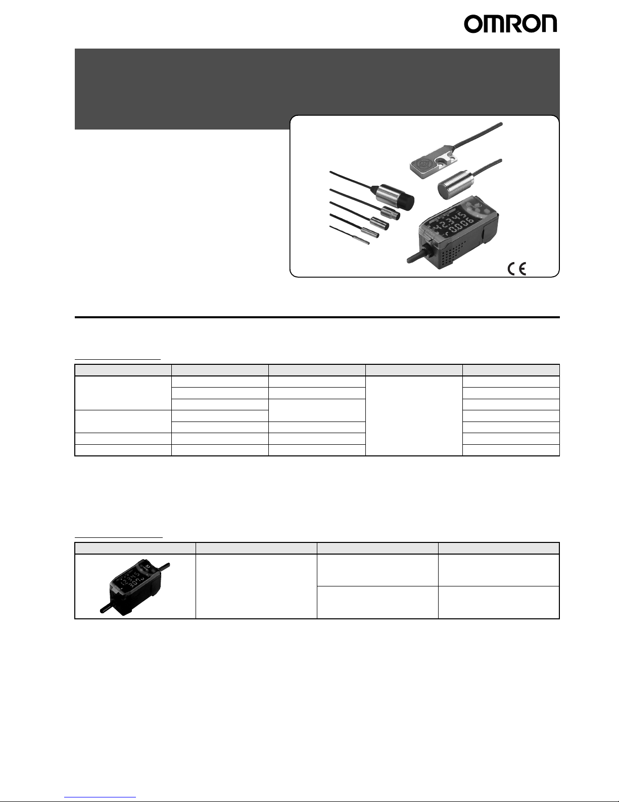
Smart Sensors (Inductive Displacement Type)
ZX-E Series
Smart Sensors that use the
eddy current method are now
available. Develop new applications with sub-micron sensing
technology.
.
Ordering Information
■ Sensors
Sensor Heads
*1: For an average count of 4,096.
*2: Models with Protective Spiral Tubes are also available. Add a suffix of “-S” to the above model numbers when ordering.
(Example: ZX-ED01T-S)
*3: Be sure to use ZX-EDA Amplifier Unit version 1,200 or later with the ZX-EV04.
*4: Be sure to use ZX-EDA Amplifier Unit version 1,300 or later with the ZX-EM02H.
Amplifier Units
Note: Compatible connection with the Sensor Head.
Shape Dimensions Sensing distance Resolution *1 Model
Cylindrical 3 dia. x 18 mm 0.5 mm 1
µmZX-EDR5T
5.4 dia. x 18 mm 1 mm ZX-ED01T *2
8 dia. x 22 mm 2 mm ZX-ED02T *2
Screw-shaped M10 x 22 mm ZX-EM02T *2
M18 x 46.3 mm 7 mm ZX-EM07MT *2
Flat 30 x 14 x 4.8 mm 4 mm ZX-EV04T *2 *3
Heat-resistant, cylindrical M12 x 22 mm 2 mm ZX-EM02HT *4
Appearance Power supply Output type Model
DC NPN ZX-EDA11
PNP ZX-EDA41
2 ZX-E Series Smart Sensors (Inductive Displacement Type)
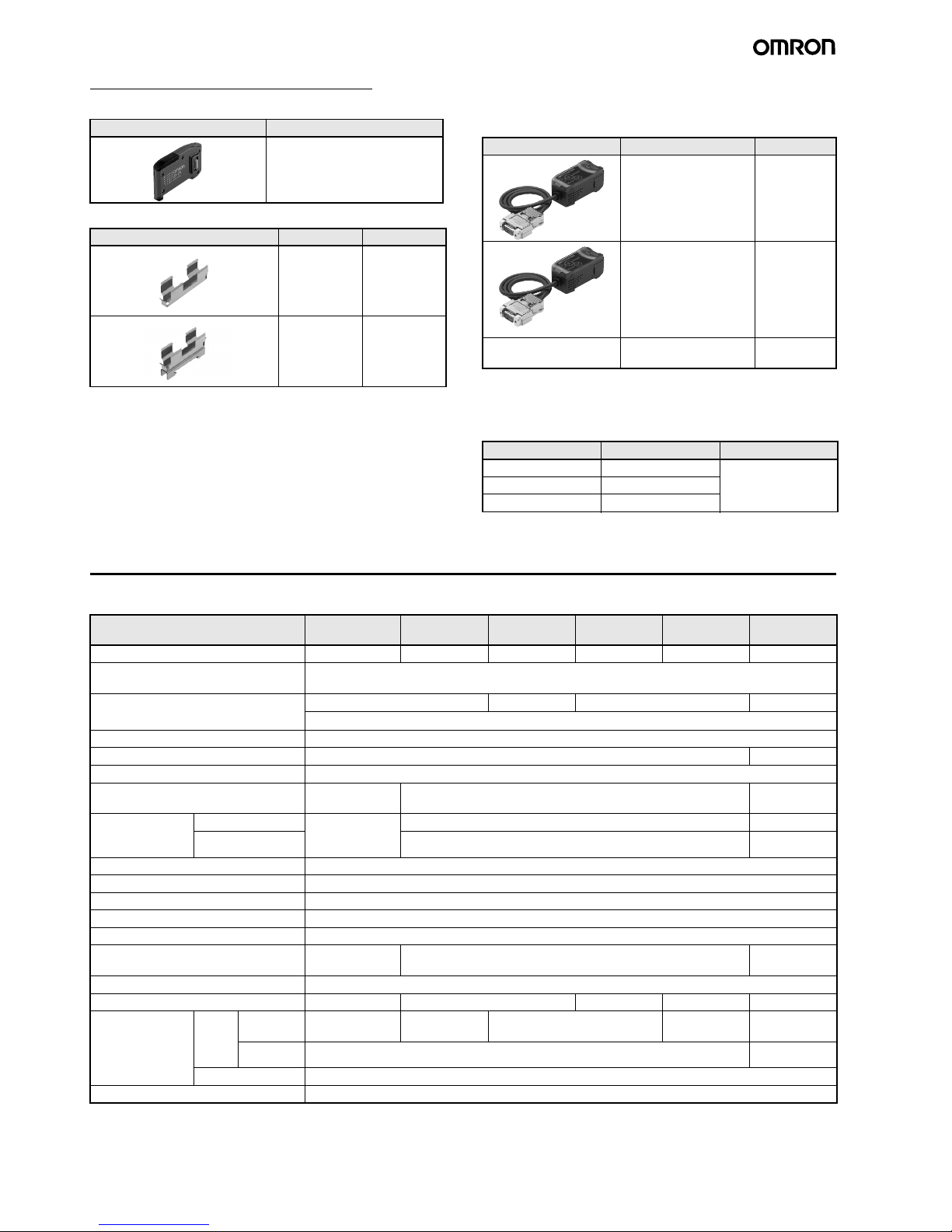
Accessories (Order Separately)
Calculating Unit
Amplifier Mounting Brackets
SmartMonitor Sensor Setup Tool for
Personal Computer Connection
* The ZX-SFW11EV3 SmartMonitor can be used only to set func-
tions and monitor waveforms.
Cables with Connectors on Both Ends (for
Extension)*
* Robot cable models are also available.
The model numbers are ZX-XC@R.
Specifications
■ Sensor Heads
Appearance Model
ZX-CAL2
Appearance Model Remarks
ZX-XBE1 Attached to
each Sensor
Head
ZX-XBE2 For DIN track
mounting
Appearance Name Model
ZX-series Communications Interface Unit
ZX-SF11
ZX-series Communications Interface Unit
+
Setup Software
ZXSFW11EV3*
CD-ROM ZX-series Sensor Setup
and Logging Software
ZX-SW11EV3
Cable length Model Quantity
1 m ZX-XC1A 1
4 m ZX-XC4A
8 m ZX-XC8A
+
CD-ROM
Model ZX-EDR5T ZX-ED01T ZX-ED02T/
EM02T
ZX-EM07MT ZX-EV04T ZX-EM02H
Measurement range 0 to 0.5 mm 0 to 1 mm 0 to 2 mm 0 to 7 mm 0 to 4 mm 0 to 2 mm
Sensing object Magnetic metals (Measurement ranges and linearities are different for non-magnetic metals. Refer to
Engineering Data on page 4.)
Standard reference object 18
×18×3 mm 30×30×3 mm 60×60×3 mm 45×45×3 mm
Material: ferrous (S50C)
Resolution *1 1
µm
Linearity *2
±0.5% F.S. ±1.0% F.S. *5
Linear output range Same as measurement range.
Temperature characteristic *3
(including Amplifier Unit)
0.15% F.S./
°C 0.07% F.S./°C0.1% F.S./°C
Ambient temperature
Operating *4
0 to 50
°C (with no
icing or condensation)
−10 to 60°C (with no icing or condensation) −10 to 200°C
Storage *4
−20 to 70°C (with no icing or condensation) −20 to 200°C
Ambient humidity Operating and storage: 35% to 85% (with no condensation)
Insulation resistance 50 M
Ω min. (at 500 DC)
Dielectric strength 1,000 VAC, 50/60 Hz for 1 min between charged parts and case
Vibration resistance (destruction) 10 to 55 Hz with 1.5-mm double amplitude for 2 h each in X, Y, and Z directions
Shock resistance (destruction) 500 m/s
2
, 3 times each in X, Y, and Z directions
Degree of protection (Sensor Head) IEC60529, IP65 IEC60529, IP67 IEC60529,
IP60 *6
Connection method Connector relay (standard cable length: 2 m)
Weight (packed state) Approx. 120 g Approx. 140 g Approx. 160 g Approx. 130 g Approx. 160 g
Materials
Sensor
Head
Case
Brass Stainless steel Brass Zinc (nickel-
plated)
Brass
Sensing
surface
Heat-resistant ABS PEEK
Preamplifier
PES
Accessories Amplifier Mounting Brackets (ZX-XBE1), Instruction Manual

ZX-E Series Smart Sensors (Inductive Displacement Type) 3
*1:Resolution: The resolution is the deviation (±3σ) in the linear output when connected to the ZX-EDA Amplifier Unit. The above values indicate
the deviations observed 30 minutes after the power is turned ON.
(The resolution is measured with OMRON's standard reference object at 1/2 of the measurement range with the ZX-EDA set for the maximum average count of 4,096 per period.)
The resolution is given at the repeat accuracy for a stationary workpiece, and is not an indication of the distance accuracy. The resolution
may be adversely affected under strong electromagnetic fields.
*2: Linearity: The linearity is given as the error in an ideal straight line displacement output when measuring the standard reference object. The
linearity and measurement values vary with the object being measured.
*3: Temperature characteristic: The temperature characteristic is measured with OMRON's standard reference object at 1/2 of the measure-
ment range.
*4: The ambient temperature given is only for the sensor head. It is -10 to 60
°C for the preamp.
*5: The value given is for an ambient temperature of 25
°C.
*6: Do not use in moist environments because the case is not waterproof.
■ Amplifier Units
*1:The response speed of the linear output is calculated as the measurement period × (average count setting + 1) (with fixed sensitivity).
The response speed of the judgement outputs is calculated as the measurement period
× (average count setting + 1) (with fixed sensitivity).
*2: The output can be switched between a current output and voltage output using a switch on the bottom of the Amplifier Unit.
*3: Setting is possible via the monitor focus function.
*4: A Calculating Unit (ZX-CAL2) is required.
Model ZX-EDA11 ZX-EDA41
Measurement period 150
µs
Possible average count settings *1 1, 2, 4, 8, 16, 32, 64, 128, 256, 512, 1,024, 2,048, or 4,096
Linear output *2 Current output: 4 to 20 mA/F.S., Max. load resistance: 300
Ω
Voltage output:±4 V (± 5 V, 1 to 5 V *3), Output impedance: 100 Ω
Judgement outputs
(3 outputs: HIGH/PASS/LOW)
NPN open-collector outputs, 30 VDC, 50 mA max.
Residual voltage: 1.2 V max.
PNP open-collector outputs, 30 VDC, 50 mA max.
Residual voltage: 2 V max.
Zero reset input, timing input, reset
input, judgement output hold input
ON: Short-circuited with 0-V terminal or 1.5 V or
less
OFF: Open (leakage current: 0.1 mA max.)
ON: Supply voltage short-circuited or supply volt-
age within 1.5 V
OFF: Open (leakage current: 0.1 mA max.)
Function - Measurement value display - Set value/output value/resolution display
- Linearity adjustment (materials selection) - Scaling
- Display reverse - Display OFF mode - ECO mode
- Number of display digit changes - Sample hold - Peak hold
- Bottom hold, peak-to-peak hold - Self-peak hold - Self-bottom hold
- Average hold - Delay hold - Zero reset
- Initial reset - Linearity initialization - ON-delay timer
- OFF-delay timer - One-shot timer - Previous value comparison
- Non-measurement setting - Direct threshold value setting - Position teaching
- Automatic teaching - Hysteresis width setting - Timing inputs
- Reset input - Judgement output hold input - Monitor focus
- Linear output correction - (A-B) calculations *4 - (A+B) calculations *4
- K-(A+B) calculation *4 - Mutual interference prevention *4
- Sensor disconnection detection - Zero reset memory - Zero reset indicator
- Key lock
Indications Judgement indicators: High (orange), pass (green), low (yellow), 7-segment main digital display (red),
7-segment sub-digital display (yellow), power ON (green), zero reset (green), enable (green)
Voltage influence
(including Sensor)
0.5% F.S. of linear output value at
±20% of power supply voltage
Power supply voltage 12 to 24 VDC
±10%, Ripple (p-p): 10% max.
Current consumption 140 mA max. with power supply voltage of 24 VDC (with Sensor connected)
Ambient temperature Operating and storage: 0
to 50°C (with no icing or condensation)
Ambient humidity Operating and storage: 35% to 85% (with no condensation)
Insulation resistance 20 M
Ω min. (at 500 DC)
Dielectric strength 1,000 VAC, 50/60 Hz for 1 min
Vibration resistance (destruction) 10 to 150 Hz with 0.7-mm double amplitude for 80 min each in X, Y, and Z directions
Shock resistance (destruction) 300 m/s
2
, 3 times each in 6 directions (up, down, left, right, forward, backward)
Connection method Prewired (standard cable length: 2 m)
Weight (packed state) Approx. 350 g
Materials Case: PBT (polybutylene terephthalate), Cover: Polycarbonate
Accessories Instruction Manual
4 ZX-E Series Smart Sensors (Inductive Displacement Type)
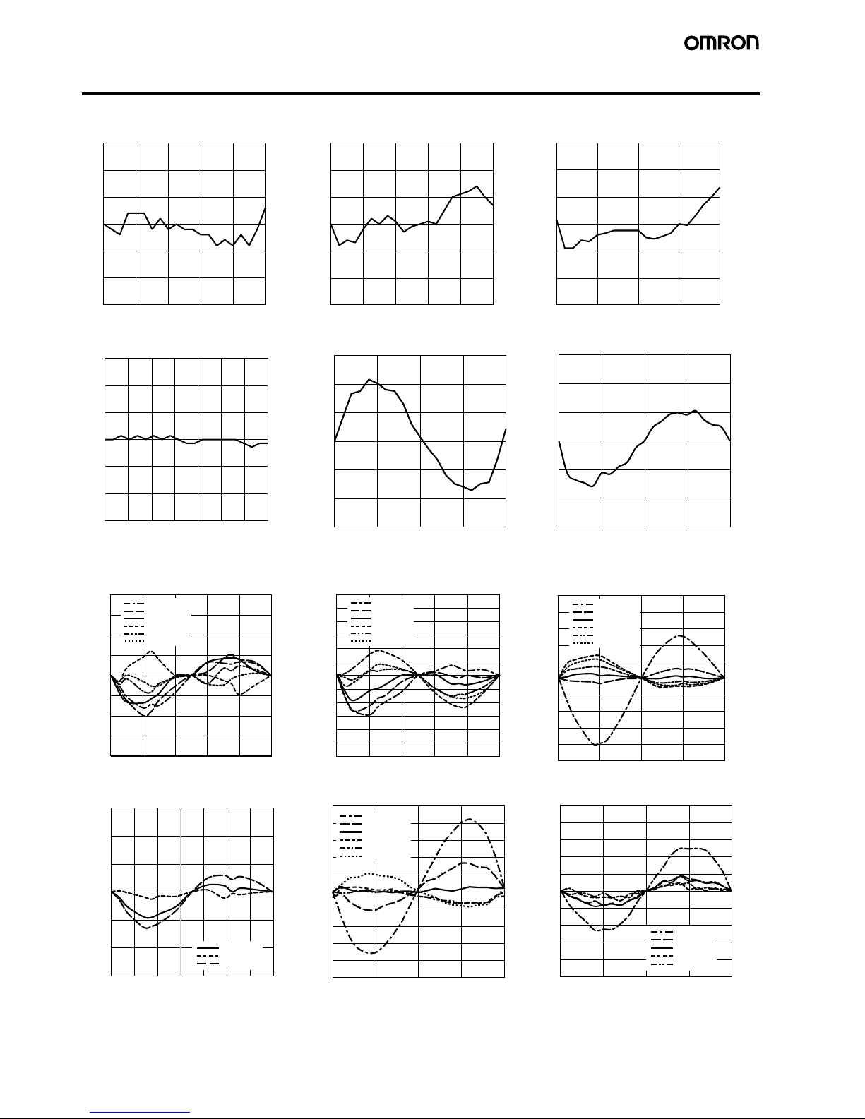
Engineering Data (Typical)
Measurement Distance vs. Linearity (with Linearity Adjusted for Standard Sensing Object)
ZX-EDR5T ZX-ED01T ZX-ED02T/ZX-EM02T
ZX-EM07MT ZX-EV04T ZX-EM02HT
Size of Sensing Object vs. Linearity (with Linearity Adjusted for Each Sensing Object)
ZX-EDR5T ZX-ED01T ZX-ED02T/ZX-EM02T
ZX-EM07MT ZX-EV04T ZX-EM02HT
0.3
0.2
0.1
0
−0.1
−0.2
−0.3
0
0.1 0.2 0.3 0.4 0.5
Linearity (% F.S.)
Measurement distance (mm)
0.3
0.2
0.1
0
−0.1
−0.2
−0.3
0
0.2 0.4 0.6 0.8 1
Linearity (% F.S.)
Measurement distance (mm)
0.3
0.2
0.1
0
−0.1
−0.2
−0.3
0
0.5 1 1.5 2
Linearity (% F.S.)
Measurement distance (mm)
0.3
0.2
0.1
0
−0.1
−0.2
−0.3
0
1234 657
Linearity (% F.S.)
Measurement distance (mm)
0.3
0.2
0.1
0
−0.1
−0.2
−0.3
Linearity (% F.S.)
Measurement distance (mm)
0.0
1.0 2.0 3.0 4.0
0.3
0.2
0.1
0
−0.1
−0.2
−0.3
Linearity (% F.S.)
Measurement distance (mm)
0
0.5 1 1.5 2
0.4
0.3
0.2
0.1
0
−0.1
−0.2
−0.3
−0.4
0
0.1 0.2 0.3 0.4 0.5
Linearity (% F.S.)
Measurement distance (mm)
S50C @5
S50C @8
S50C @12
S50C @18
S50C @30
S50C @45
0.6
0.5
0.4
0.3
0.2
0.1
0
−0.1
−0.2
−0.3
−0.4
−0.5
−0.6
0
0.2 0.4 0.6 0.8 1
Linearity (% F.S.)
Measurement distance (mm)
S50C @5
S50C @8
S50C @12
S50C @18
S50C @30
S50C @45
1.0
0.8
0.6
0.4
0.2
0
−0.2
−0.4
−0.6
−0.8
−1.0
Linearity (% F.S.)
Measurement distance (mm)
S50C @5
S50C @8
S50C @12
S50C @18
S50C @30
S50C @45
0
0.5 1 1.5 2
Linearity (% F.S.)
0.3
0.2
0.1
0
−0.1
−0.2
−0.3
Measurement distance (mm)
0
1234 567
S50C @30
S50C @45
S50C @60
Linearity (% F.S.)
Measurement distance (mm)
1
0.8
0.6
0.4
0.2
0
−0.2
−0.4
−0.6
−0.8
−1
0.0
1.0 2.0 3.0 4.0
S50C @8
S50C @12
S50C @18
S50C @30
S50C @45
S50C @60
Linearity (% F.S.)
Measurement distance (mm)
0
0.5 1 1.5 2
0.5
0.4
0.3
0.2
0.1
0
−0.1
−0.2
−0.3
−0.4
−0.5
S50C @8
S50C @12
S50C @18
S50C @30
S50C @45
ZX-E Series Smart Sensors (Inductive Displacement Type) 5
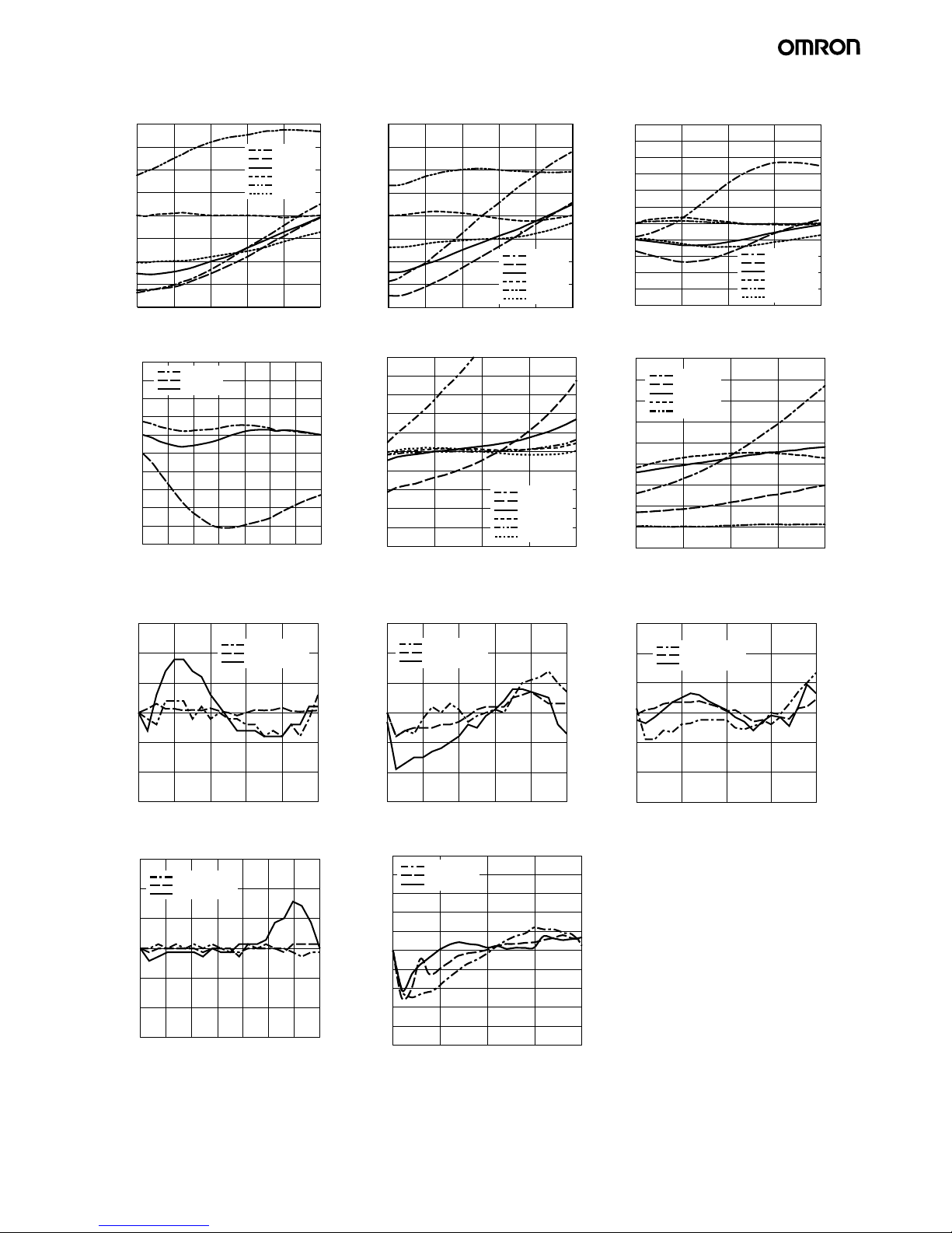
Size of Sensing Object vs. Linearity (with Linearity Adjusted for Standard Sensing Object)
ZX-EDR5T ZX-ED01T ZX-ED02T/ZX-EM02T
ZX-EM07MT ZX-EV04T ZX-EM02HT
Material of Sensing Object vs. Linearity (
with Linearity Adjusted for Each Sensing Object)
ZX-EDR5T ZX-ED01T ZX-ED02T/ZX-EM02T
ZX-EM07MT ZX-EV04T
Linearity (% F.S.)
Measurement distance (mm)
4
3
2
1
0
−1
−2
−3
−4
0
0.1 0.2 0.3 0.4 0.5
S50C @5
S50C @8
S50C @12
S50C @18
S50C @30
S50C @45
Linearity (% F.S.)
Measurement distance (mm)
4
3
2
1
0
−1
−2
−3
−4
0
0.2 0.4 0.6 0.8 1
S50C @5
S50C @8
S50C @12
S50C @18
S50C @30
S50C @45
Linearity (% F.S.)
Measurement distance (mm)
6
5
4
3
2
1
0
−1
−2
−3
−4
−5
S50C @5
S50C @8
S50C @12
S50C @18
S50C @30
S50C @45
0
0.5 1 1.5 2
Linearity (% F.S.)
Measurement distance (mm)
0.8
0.6
0.4
0.2
0
−0.2
−0.4
−0.6
−0.8
−1
−1.2
S50C @30
S50C @45
S50C @60
01234567
5
4
3
2
1
0
−1
−2
−3
−4
−5
0.0
1.0 2.0 3.0 4.0
S50C @8
S50C @12
S50C @18
S50C @30
S50C @45
S50C @60
Linearity (% F.S.)
Measurement distance (mm)
Linearity (% F.S.)
Measurement distance (mm)
8
7
6
5
4
3
2
1
0
−1
S50C @8
S50C @12
S50C @18
S50C @30
S50C @45
0
0.5 1 1.5 2
0.3
0.2
0.1
0
−0.1
−0.2
−0.3
0
0.1 0.2 0.3 0.4 0.5
Linearity (% F.S.)
Measurement distance (mm)
S50C @18
SUS304 @18
A5052 @18
0.3
0.2
0.1
0
−0.1
−0.2
−0.3
0
0.2 0.4 0.6 0.8 1
S50C @18
SUS304 @18
A5052 @18
Linearity (% F.S.)
Measurement distance (mm)
0.3
0.2
0.1
0
−0.1
−0.2
−0.3
S50C @30
SUS304 @30
A5052 @30
Measurement distance (mm)
0
0.5 1 1.5 2
Linearity (% F.S.)
0.3
0.2
0.1
0
−0.1
−0.2
−0.3
0
1234 657
Linearity (% F.S.)
Measurement distance (mm)
S50C @60
SUS304 @60
A5052 @60
Linearity (% F.S.)
Measurement distance (mm)
0.5
0.4
0.3
0.2
0.1
0
−0.1
−0.2
−0.3
−0.4
−5
0.0
1.0 2.0 3.0 4.0
S50C @60
SUS304 @60
A5052 @60
 Loading...