

Page 1
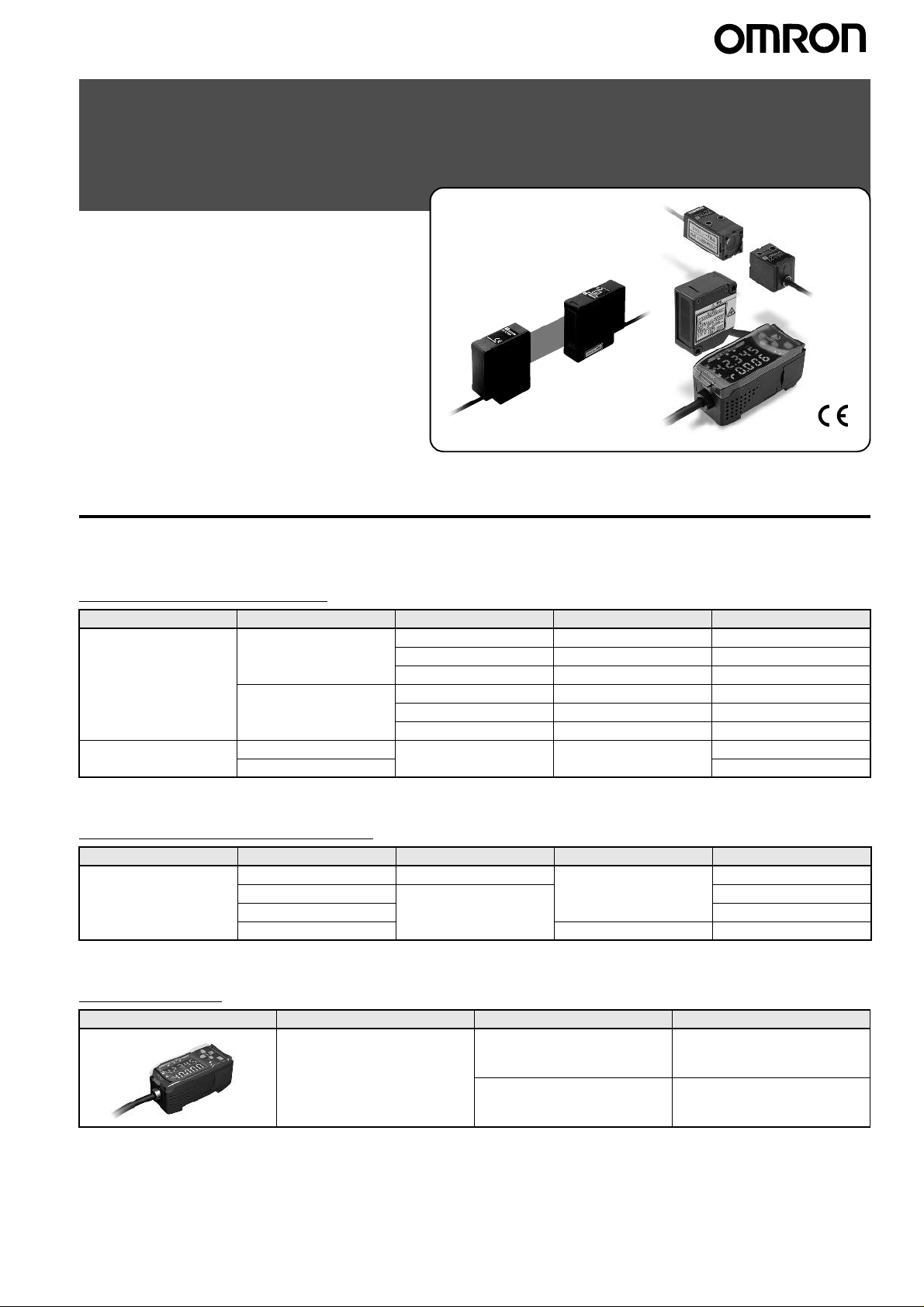
Smart Sensors (Laser Type)
ZX Series (ZX-L-N)
Ordering Information
■Sensors
.
Sensor Heads (Reflective)
Optical system Beam shape Sensing distance Resolution*1 Model
Diffuse reflective Spot beam 40
Line beam 40
Regular reflective Spot beam 30
Line beam ZX-LD30VL
*1.For an average count of 4,096.
±10 mm 2 µm ZX-LD40
100
±40 mm 16 µm ZX-LD100
300
±200 mm 300 µm ZX-LD300
±10 mm 2 µm ZX-LD40L
100
±40 mm 16 µm ZX-LD100L
300
±200 mm 300 µm ZX-LD300L
±2 mm 0.25 µm ZX-LD30V
Sensor Heads (Through-beam)
Optical system Measuring width Sensing distance Resolution*1 Model
Through-beam 1-mm dia. 0 to 2000 mm 4
5 mm 0 to 500 mm ZX-LT005
10 mm ZX-LT010
30 mm 12
*1.For an average count of 64.
µm ZX-LT001
µm ZX-LT030
Amplifier Units
Appearance Powe r su pply Output type Model
DC NPN ZX-LDA11-N
Note: Compatible connection with the Sensor Head.
PNP ZX-LDA41-N
ZX Series (ZX-L-N) Smart Sensors (Laser T ype) 1
Page 2
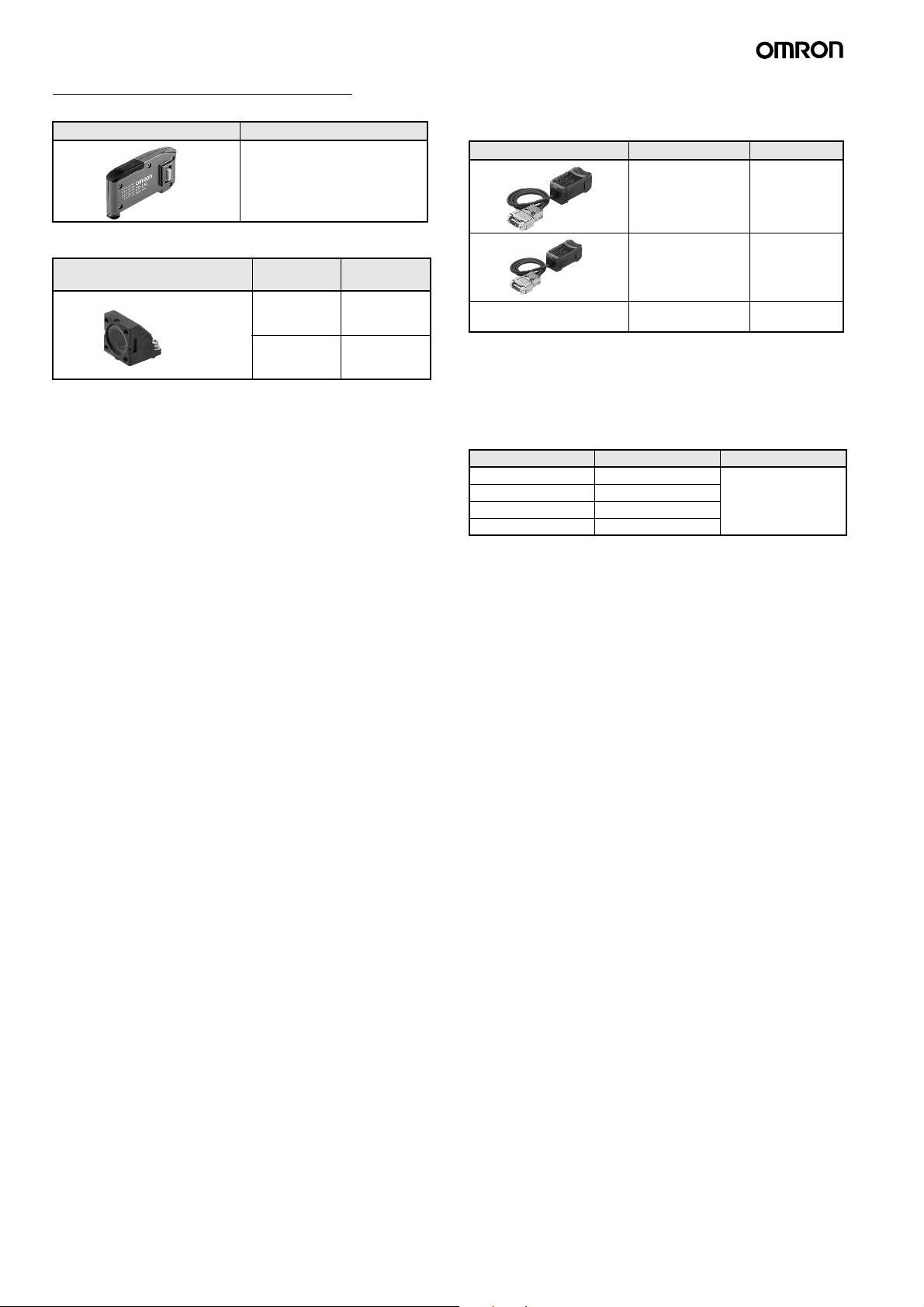
Accessories (Order Separately)
Calculat ing Unit
Appearance Model
ZX-CAL2
SmartMonitor Sen s or Setup Tool for
Personal Computer Connection
Appearance Name Model
ZX-series Communications Interface
Unit
ZX-SF11
Side-view Attachments
Appearance Applicable
Sensor Head
ZX-LT1001/
LT005
ZX-LT010 ZX-XF22
Model
ZX-XF12
ZX-series Communications Interface
+
CD-ROM
CD-ROM ZX-series Sensor
*1. When using the ZX-LDA11-N/41-N with the SmartMonitor, either the ZX-
SFW11EV3 or the ZX-SW11EV3 SmartMonitor must be used. Earlier versions cannot be used.
*2. The ZX-SFW11EV3 SmartMonitor can be used only to set functions and
monit o r wave fo rms.
Unit + ZX-series
Sensor Setup Software Basic
Setup Software
ZX-SFW11EV3
*1*2
ZX-SW11EV3
*1
Cables wit h C onnectors on Both Ends (for
Extension)*1
Cable length Model Quantity
1 m ZX-XC1A 1
4 m ZX-XC4A
8 m ZX-XC8A
9 m *2 ZX-XC9A
*1. Robot Cable models are also available. The model numbers are ZX-XC@R.
*2.For use only with Reflective Sensors.
2 ZX Series (ZX-L-N) Smart Sensors (Laser Type)
Page 3
Specifications
■Sensor Heads (Reflective)
Item Model ZX-LD40 ZX-LD100 ZX-LD300 ZX-LD30V ZX-LD40L ZX-LD100L ZX-LD300L Z3X-LD30VL
Optical system Diffuse reflective Regular re-
Light source (wave
length)
Measurement point 40 mm 100 mm 300 mm 30 mm 40 mm 100 mm 300 mm 30 mm
Measurement range
Beam shape Spot Line
Beam size*1
Resolution*2
Linearity*3
Temperature
characteristic*4
Ambient illumination Incandescent lamp: 3,000 l
Ambient temperature Operating: 0 to 50
Ambient humidity Operating and storage: 35% to 85% (with no condensation)
Insulation resistance 20 M
Dielectric strength 1,000 VAC, 50/60 Hz for 1 min
Vibration resistance
(destruction)
Shock resistance
(destruction)
Degree of protection IEC60529, IP50 IEC60529,
Connection method Connector relay (standard cable length: 500 mm)
Weight (packed state) Approx. 150 g Approx. 250 gApprox. 150 g Approx. 250 g
Visible-light semiconductor laser with a wavelength of 650 nm and an output of 1 mW max.
EN class 2, FDA class II
±10 mm ±40 mm ±200 mm ±2 mm ±10 mm ±40 mm ±200 mm ±2 mm
µm dia. 100-µm dia. 300-µm dia. 75-µm dia. 75 µm x 2
50-
µm16 µm 300 µm 0.25 µm2 µm 16 µm300 µm 0.25 µm
2
±0.2% FS
(entire
range)
±0.03% FS/°C (Except for ZX-LD300 and ZX-LD300L, which are ±0.1% FS/°C.)
Ω min. at 500 VDC
10 to 150 Hz, 0.7-mm double amplitude 80 min each in X, Y, and Z directions
300 m/s
±0.2% FS
(80 to 120
mm)
°C, Storage: −15 to 60°C (with no icing or condensation)
2
3 times each in six directions (up/down, left/right, forward/backward)
±2% FS
(200 to 400
mm)
× max. (on light receiving side)
flective
±0.2% FS
(entire
range)
IP40
Diffuse reflective Regular reflec-
mm
±0.2% FS
(32 to 48
mm)
IEC60529, IP50 IEC60529,
150 µm x 2 mm450 µm x 2 mm100 µm x 1.8
±0.2% FS
(80 to 120
mm)
±2% FS
(200 to 400
mm)
tive
mm
±0.2% FS
(entire range)
IP40
Materials Case: PBT (polybutylene terephthalate),
Accessories Instruction sheet, Laser warning label (English)
*1.Beam size: The beam size is defined by 1/e
occur if there is light leakage outside the defined spot and the material around the sensing object is more reflective than the sensing object.
*2.Resolution: The resolution is the deviation (
with the standard reference object (white ceramic), at the measurement point with the ZX-LDA set for an average count of 4,096 per period.)
The resolution is given at the repeat accuracy for a stationary workpiece, and is not an indication of the distance accuracy. The resolution may
be adversely affected under strong electromagnetic fields.
*3.Linearity: The linearity is given as the error in an ideal straight line displacement output when measuring the standard reference object. The
linearity and measurement values vary with the object being measured.
*4.Temperature characteristic: The temperature characteristic is measured at the measurement point with the Sensor and reference object
(OMRON’s standard reference object) secured with an aluminum jig.
Note: Highly reflective objects can result in incorrec t detection by causing out-of-range measurement s.
Cover: Aluminum, Lens: Glass
2
(13.5%) of the strength of the beam at the beam center (measured value). Incorrect detection may
±3σ) in the linear output when connected to the ZX-LDA Amplifier Unit. (The resolution is measured
Case and
cover: Aluminum, Lens:
Glass
Case: PBT (polybutylene terephthalate),
Cover: Aluminum, Lens: Glass
Case and cover: Aluminum,
Lens: Glass
ZX Series (ZX-L-N) Smart Sensors (Laser T ype) 3
Page 4
■Sensor Heads (Through-beam)
Item Model ZX-LT001 ZX-LT005 ZX-LT010 ZX- LT030
Optical system Through-beam
Light source
(wave length)
Maximum output 0.2 mW max. 0.35 mW max. 0.2 mW max.
Measurement width 1-mm dia. 1- to 2.5-mm dia. 5 mm 10 mm 30 mm
Measurement
distance
Minimum sensing
object
Resolution*1
Temperature
characteristic
Ambient illumination Incandescent lamp: 10,000 l
Ambient temperature Operating: 0 to 50
Ambient humidity Operating: 35% to 85% (with no condensation)
Degree of protection IEC60529, IP40
Connection method Connector relay (standard cable length: 500 mm)
Weight (packed state) Approx. 220 g Approx. 450 g
Cable length Extendable up to 10 m with special extension cable.
Materials Case Polyether imide Zinc die-cast
Cover Polycarbonate
Front filter Glass
Tightening torque 0.3 N
Accessories Instruction sheet, Sensor Head-Amplifier Connection Cable
*1.This value is obtained by converting the deviation (
into the measurement width.
*2.For an average count of 64. The value is 5
This is the value that results when a minimum sensing object blocks the light near the center of the 1-mm measurement width.
*3.For an average count of 64. The value is 5
*4.For an average count of 64. The value is 15
Visible-light semiconductor laser with a wavelength of 650 nm
EN class 1, FDA class II
0 to 500 mm 500 to 2,000 mm 0 to 500 mm
8-
µm dia.
(opaque)
µm *2
4
±0.2% FS/°C ±0.3% FS/°C
⋅m max.
Optical axis adjustment seal Mounting Bracket
8- to 50-µm dia.
(opaque)
--- 4
× max. (on light-receiving side)
°C, Storage: −25 to 70°C (with no icing or condensation)
±3σ) in the linear output that results when the sensor head is connected to the amplifier unit,
µm for an average count of 32.
µm for an average count of 32.
µm for an average count of 32.
0.05-mm dia. (opaque) 0.1-mm dia. (opaque) 0.3-mm dia. (opaque)
µm *3
12
µm *4
4 ZX Series (ZX-L-N) Smart Sensors (Laser Type)
Page 5
■Amplifier Units
Item Model ZX-LDA11-N ZX-LDA41-N
Measurement period 150
Possible average count settings*1
Temperature characteristic When connected to a Reflective Sensor Head: 0.01% FS/
Linear output*2
Judgement outputs
(3 outputs: HIGH/PASS/LO W)*1
Laser OFF input, zero reset input,
timing input, reset input
Functions Measurement value display, present value/set value/light le vel/resolution displa y, scaling, display re verse ,
Indications Operation indicators: High (orange), pass (green), low (yellow), 7-segment main display (red), 7-segment
Power supply voltage 12 to 24 VDC
Current consumption 140 mA max. with power supply voltage of 24 VDC (with Sensor connected)
Ambient temperature Operating: 0
Ambient humidity Operating and storage: 35% to 85% (with no condensation)
Insulation resistance 20 M
Dielectric strength 1,000 VAC, 50/60 Hz for 1 min
Vibration resistance
(destruction)
Shock resistance
(destruction)
Connection method Prewired (standard cable length: 2 m)
Weight (packed state) Approx. 350 g
Materials Case: PBT (polybutylene terephthalate), Cover: Polycarbonate
Accessories Instruction sheet
*1.The response speed of the linear output is calculated as the measurement period
The response speed of the judgement outputs is calculated as the measurement period
*2.The output can be switched between a current output and voltage output using a switch on the bottom of the Amplifier Unit.
*3.Setting is possible via the monitor focus function.
*4.A Calculating Unit (ZX-CAL2) is required.
µs
1, 2, 4, 8, 16, 32, 64, 128, 256, 512, 1,024, 2,048, or 4,096
Head: 0.1% FS/
4 to 20 mA/FS, Max. load resistance: 300
NPN open-collector outputs, 30 VDC, 50 mA max.
Residual voltage: 1.2 V max.
ON: Short-circuited with 0-V terminal or 1.5 V or less
OFF: Open (leakage current: 0.1 mA max.)
display OFF mode, ECO mode, number of display digit changes, sample hold, peak hold, bottom hold,
peak-to-peak hold, self-peak hold, self-bottom hold, average hold, delay hold, intensity mode, zero reset,
initial reset, ON-delay timer, OFF-delay timer, one-shot timer, deviation, previous value comparison,
sensitivity adjustment, keep/clamp switch, direct threshold value setting, position teaching, 2-point
teaching, automatic teaching, hysteresis width setting, timing inputs, reset input, monitor focus, linear
output compensation, (A-B) calculations*4, (A+B) calculations*4, mutual interference*4, laser
deterioration detection, zero reset memory, zero reset display, key lock
subdisplay (yellow), laser ON (green), zero reset (green), enable (green)
Ω min. at 500 VDC
10 to 150 Hz, 0.7-mm double amplitude 80 min each in X, Y, and Z directions
300 m/s
°C
Ω, ±4 V (± 5 V, 1 to 5 V *3), Output impedance: 100 Ω
±10%, Ripple (p-p): 10% max.
to 50°C, Storage: −15 to 60°C (with no icing or condensation)
2
3 times each in six directions (up/down, left/right, forward/backward)
°C, When connected to a Through-beam Sensor
PNP open-collector outputs, 30 VDC, 50 mA max.
Residual voltage: 2 V max.
ON: Supply voltage short-circuited or supply voltage
within 1.5 V
OFF: Open (leakage current: 0.1 mA max.)
× (average count setting + 1) (with fixed sensitivity).
× (average count setting + 1) (with fixed sensitivity).
ZX Series (ZX-L-N) Smart Sensors (Laser T ype) 5
Page 6
■Calculating Unit
Item ZX-CAL2
Applicable Amplifier Units ZX-LDA11-N/41-N/ZX-EDA11/41/ZX-TDA11/41
Current consumption 12 mA max. (supplied from the Smart Sensor Amplifier Unit)
Ambient temperature Operating: 0 to 50
Ambient humidity Operating and storage: 35% to 85% (with no condensation)
Connection method Connector
Dielectric strength 1,000 VAC, 50/60 Hz for 1 min
Insulation resistance 100 M
Vibration resistance (destructive) 10 to 150 Hz, 0.7-mm double amplitude 80 min each in X, Y, and Z directions
Shock resistance (destructive) 300 m/ s
Materials Display: Acrylic, Case: ABS resin
Weight (packed state) Approx. 50 g
Ω (at 500 VDC)
2
3 times each in six directions (up/down, left/right, forward/backward)
°C, Storage: −15 to 60°C (with no icing or condensation)
■ZX-series Communications Interface Unit
Item ZX-SF11
Current consumption 60 mA max. (supplied by the Amplifier Unit)
Applicable Amplifier Units ZX Series
Applicable A m plifier Unit versions ZX-LDA@1-N Ver. 1.000 or higher
Max. No. of Amplifier Units 5
Communications
functions
Indicators Power supply: green, Sensor communications: green, Sensor communications error: red, External
Protective circuits Reverse polarity protection
Ambient temperature Operating: 0 to 50
Ambient humidity Operating and storage: 35% to 85% (with no condensation)
Insulation resistance 20 M
Dielectric strength 1,000 VAC, 50/60 Hz for 1 min, Leakage current: 10 mA max.
Materials Case: PBT (polybutylene terephthalate), Cover: Polycarbonate
Accessories Instruction sheet, 2 clamps
* Contact your OMRON representative for CompoWay/F communications specifications.
Communications
port
Communications
protocol
Baud rate 38,400 bps
Data configuration Data bits: 8, Parity: none, Start bits: 1, Stop bits: 1, Flow control: none
ZX-EDA@1 Ver. 1.100 or higher
ZX-TDA@1 Ver. 1.000 or higher
RS-232C port (9-pin D-Sub Connector)
CompoWay/F*
terminal communications: green, External terminal communications error: red
°C, storage: −15 to 60°C (with no icing or condensation)
Ω min. (at 500 VDC)
6 ZX Series (ZX-L-N) Smart Sensors (Laser Type)
Page 7
Engineering Data (Ty pical)
Angle Characteristic (Reflective Sensors)
The angle characteristic plots the relation between the inclination of the measurement object and the error in the linear output at the meas urement point.
Note: SUS304 = Stainless steel SUS304
●ZX-LD40
Side-to-side Inclination
4
3
+ inclination
2
Error (% FS)
−1
−2
−3
−4
Front-to-back Inclination
4
3
2
Error (% FS)
1
0
−1
−2
−3
−4
− inclination
1
0
−8 −6 −4 −20246810
−10
−8 −6 −4 −20246810
−10
Angle of inclination (°)
Angle of inclination (°)
White ceramic
SUS304
Black paper
White ceramic
SUS304
Black paper
+ inclination
− inclination
●ZX-LD100
Side-to-side Inclination
4
3
+ inclination
2
Error (% FS)
−1
−2
−3
−4
Error (% FS)
− inclination
1
0
−8 −6 −4 −20246810
−10
Angle of inclination (°)
Front-to-ba ck Inclination
4
3
+ inclination
2
− inclination
1
0
−1
−2
−3
−4
−8 −6 −4 −20246810
−10
Angle of inclination (°)
White ce ramic
SUS304
Black paper
White ceramic
SUS304
Black paper
●ZX-LD300
Side-to-side Inclination
20
15
10
Error (% FS)
5
0
−5
−10
−15
−20
−8 −6 −4 −20246810
−10
Front-to-back Inclination
20
15
10
Error (% FS)
5
0
−5
−10
−15
−20
−8 −6 −4 −20246810
−10
Angle of inclination (°)
Angle of inclination (°)
White ceramic
SUS304
Black
paper
+ inclination
− inclination
White ceramic
SUS304
Black paper
+ inclination
− inclination
●ZX-LD40L
Side-to-side Inclination
4
3
+ inclination
2
Error (% FS)
−1
−2
−3
−4
Error (% FS)
− inclination
1
0
−8 −6 −4 −20246810
−10
Angle of inclination (°)
Front-to-back Inclination
4
3
2
1
0
−1
−2
−3
−4
−8 −6 −4 −20246810
−10
Angle of inclination (°)
White ce ramic
SUS304
Black paper
White ceramic
SUS304
Black paper
+ inclination
− inclination
●ZX-LD100L
Side-to-side Inclination
4
3
+ inclination
2
Error (% FS)
−1
−2
−3
−4
Error (% FS)
− inclination
1
0
−8 −6 −4 −20246810
−10
Angle of inclination (°)
Front-to-back Inclination
4
3
+ inclination
2
− inclination
1
0
−1
−2
−3
−4
−8 −6 −4 −20246810
−10
Angle of inclination (°)
White ceramic
SUS304
Black paper
White ce ramic
SUS304
Black paper
●ZX-LD300L
Side-to-side Inclination
4
3
2
Error (% FS)
1
0
−1
−2
−3
−4
−8 −6 −4 −20246810
−10
Front-to-back Inclination
20
15
10
Error (% FS)
5
0
−5
−10
−15
−20
−8 −6 −4 −20246810
−10
White ceramic
SUS304
Black paper
Angle of inclination (°)
Angle of inclination (°)
White ceramic
SUS304
Black paper
+ inclination
− inclination
+ inclination
− inclination
ZX Series (ZX-L-N) Smart Sensors (Laser T ype) 7
Page 8
●ZX-LD30V
Side-to-sid e In cli nation
4
3
+ inclination
2
− inclination
1
0
−1
Linearity error (%FS)
−2
−3
−4
−8 −6 −4 −20246810
−10
Front-to-back Inclination
4
3
2
1
0
Linearity error (%FS)
−1
−2
−3
−4
−8 −6 −4 −20246810
−10
Angle of inclination (°)
+ inclination
− inclination
Angle of inclination (°)
White ceramic
SUS304
Black paper
White ce ramic
SUS304
Black paper
●ZX-LD30VL
Side-to-side Inclination
4
3
+ inclination
2
− inclination
1
0
−1
Linearity error (%FS)
−2
−
3
−4
−8 −6 −4 −20246810
−10
Front-to-back Inclination
4
3
2
1
0
Linearity error (%FS)
−1
−2
−3
−4
−8 −6 −4 −20246810
−10
Angle of inclination (°)
+ inclination
− inclination
Angle of inclination (°)
White ceramic
SUS304
Black paper
White ceramic
SUS304
Black paper
8 ZX Series (ZX-L-N) Smart Sensors (Laser Type)
Page 9
Linearity Characteristic for Different Materials (Reflective Sensors)
●ZX-LD40
0° Inclination
4
3
2
Error (% FS)
0° inclination
1
0
−1
−2
−3
−4
●ZX-LD100
0° Inclination
4
3
2
Error (% FS)
0° inclina t i o n
1
0
−1
−2
−3
−4
60
●ZX-LD300
0° Inclination
5
4
3
Error (% FS)
2
1
0
−1
−2
−3
−4
0° inclination
−5
White ceramic
SUS304
Black paper
4644 48 5040 4236 38343230
Distance (mm)
White ceramic
SUS304
Black paper
124116 132 140100 10884 927668
Distance (mm)
White ceramic
SUS304
Black paper
420380 460 500300 340220 260180140100
Distance (mm)
−10° Inclination Front-to-back
4
White ceramic
SUS304
3
Black paper
2
Error (% FS)
1
0
−1
−2
−3
−10° inclination
−4
4644 48 5040 4236 38343230
Distance (mm)
−10° Inclination Front-to-back
4
3
2
Error (% FS)
−10° inclin at i o n
1
0
−1
−2
−3
−4
60 124116 132 140100 10884 927668
White ceramic
SUS304
Black paper
Distance (mm)
−10° Inclination Front-to-back
5
4
3
Error (% FS)
2
1
0
−1
−2
−3
−4
−10° inclination
−5
White ceramic
SUS304
Black paper
420380 460 500300 340220 260180140100
Distance (mm)
° Inclination
10
4
3
2
Error (% FS)
10° inclination
1
0
−1
−2
−3
−4
10
° Inclination
4
3
2
Error (% FS)
10° inclination
1
0
−1
−2
−3
−4
60 124116 132 140100 10884 927668
° Inclination
10
5
4
3
Error (% FS)
2
1
0
−1
−2
−3
−4
10° inclination
−5
White ceramic
SUS304
Black paper
4644 48 5040 4236 38343230
Distance (mm)
White ceramic
SUS304
Black paper
Distance (mm)
White ceramic
SUS304
Black paper
420380 460 500300 340220 260180140100
Distance (mm)
●ZX-LD40L
0° Inclination
4
3
2
Error (% FS)
0° inclination
1
0
−1
−2
−3
−4
30
White ceramic
SUS304
Black paper
4644 48 5040 4236 383432
Distance (mm)
10
−10° Inclination Front-to-back
4
3
2
Error (% FS)
1
0
−1
−2
−3
−10° inclination
−4
30
White ce ramic
SUS304
Black
paper
4644 48 5040 4236 383432
Distance (mm)
° Inclination
4
3
2
Error (% FS)
10° inclination
1
0
−1
−2
−3
−4
30
White ceramic
SUS304
Black paper
4644 48 5040 4236 383432
Distance (mm)
ZX Series (ZX-L-N) Smart Sensors (Laser T ype) 9
Page 10

●ZX-LD100L
0° Inclination
4
3
2
Error (% FS)
0° inclination
1
0
−1
−2
−3
−4
60 124116 132 140100 10884 927668
White ceramic
SUS304
Black paper
Distance (mm)
−10° Inclinatio n Front-to-back
4
3
2
Error (% FS)
−10° inclination
1
0
−1
−2
−3
−4
60 124116 132 140100 10884 927668
White ceramic
SUS304
Black paper
Distance (mm)
10
° Inclination
4
3
2
Error (% FS)
10° inclination
1
0
−1
−2
−3
−4
60 124116 132 140100 10884 927668
White ceramic
White ceramic
SUS304
SUS304
Black paper
Black paper
Distance (mm)
●ZX-LD300L
0° Inclination
4
3
2
Error (% FS)
0° inclination
1
0
−1
−2
−3
−4
●ZX-LD30V
0° Inclinatio n
1.0
0.8
0.6
Error (% FS)
0.4
0.2
0
−0.2
−0.4
−0.6
−0.8
0° inclination
−1.0
28.4 28.8 29.2 29.6 30.0 30.4 30.8 31.2 31.632.0
28.0
White ceramic
SUS304
Black paper
420380 460 500300 340220 260180140100
Distance (mm)
White ce ramic
SUS304
Black paper
Distance (mm)
−10° Inclination Front-to-back
4
3
2
Error (% FS)
−10° inclination
1
0
−1
−2
−3
−4
White ceramic
SUS304
Black paper
420380 460 500300 340220 260180140100
Distance (mm)
−10° Inclinatio n Front-to-back
1.0
0.8
0.6
Error (% FS)
0.4
−10° inclination
0.2
0
−0.2
−0.4
−0.6
−0.8
−1.0
28.4 28.8 29.2 29.6 30.0 30.4 30.8 31.2 31.632.0
28.0
White ceramic
SUS304
Black paper
Distance (mm)
° Inclination
10
4
3
2
Error (% FS)
10° inclination
1
0
−1
−2
−3
−4
° Inclination
10
1.0
0.8
0.6
Error (% FS)
0.4
10° inclination
0.2
0
−0.2
−0.4
−0.6
−0.8
−1.0
28.4 28.8 29.2 29.6 30.0 30.4 30.8 31.2 31.632.0
28.0
White ceramic
SUS304
Black paper
420380 460 500300 340220 260180140100
Distance (mm)
White ceramic
SUS304
Black paper
Distance (mm)
●ZX-LD30VL
0° Inclination
1.0
0.8
0.6
Error (% FS)
0.4
0.2
0
−0.2
−0.4
−0.6
−0.8
0° inclination
−1.0
28.4 28.8 29.2 29.6 30.0 30.4 30.8 31.2 31.632.0
28.0
White ceramic
SUS304
Black paper
Distance (mm)
−10° Inclination Front-to-back
1.0
0.8
0.6
Error (% FS)
0.4
−10° inclination
0.2
0
−0.2
−0.4
−0.6
−0.8
−1.0
28.4 28.8 29.2 29.6 30.0 30.4 30.8 31.2 31.632.0
28.0
White ceramic
SUS304
Black paper
Distance (mm)
10 ZX Series (ZX-L-N) Smart Sensors (Laser Type)
° Inclination
10
1.0
0.8
0.6
Error (% FS)
0.4
10° inclination
0.2
0
−0.2
−0.4
−0.6
−0.8
−1.0
28.4 28.8 29.2 29.6 30.0 30.4 30.8 31.2 31.632.0
28.0
White ceramic
SUS304
Black paper
Distance (mm)
Page 11

Beam Size
(Reflective Sensors)
●Spot Beams
●Spot Beams
L
L
Beam cross-section
Y
X
ZX-LD40
L 30 mm 40 mm 50 mm
X 240 µm 40.0 µm 250 µm
Y 350 µm 30.0 µm 370 µm
ZX-LD100
L 60 mm 100 mm 140 mm
X 390 µm 100 µm 430 µm
Y 620 µm 65.0 µm 650 µm
ZX-LD300
L 100 mm 300 mm 500 mm
X 1,050 µm 180 µm 1,100 µm
Y 450 µm 300 µm 850 µm
●Line Beams
L
Beam cross-section
Y
X
ZX-LD30V
L 28 mm 30 mm 32 mm
X 60.0 µm 30.0 µm 120 µm
Y 50.0 µm 40.0 µm 90.0 µm
●Line Beams
L
Beam cross-section
Y
X
ZX-LD30VL
L 28 mm 30 mm 32 mm
X 1,800 µm 1,800 µm 1,800 µm
Y 90.0 µm 60.0 µm 110 µm
Beam cross-section
Y
X
ZX-LD40L
L 30 mm 40 mm 50 mm
X 2,000 µm 2,000 µm 2,000 µm
Y 240 µm 50.0 µm 250 µm
ZX-LD100L
L 60 mm 100 mm 140 mm
X 2,000 µm 2,000 µm 2,000 µm
Y 410 µm 100 µm 430 µm
ZX-LD300L
L 100 mm 300 mm 500 mm
X 2,000 µm 2,000 µm 2,500 µm
Y 750 µm 300 µm 650 µm
ZX Series (ZX-L-N) Smart Sensors (Laser T ype) 11
Page 12

Sensing Object Characteristics (Through-beam Sensors)
●ZX-LT001
(For 0.02-mm-dia. pin gauge)
2
0
−2
−4
−6
−8
−10
−12
−14
Linear (analog) output (%FS)
−16
−18
Emitter side
−1.5 −0.5 0.5 1.5 2.5
−2.5
Light axis center
Sensing distance: 500 mm
Sensing object: 0.02-mm dia.
Pin gauge
WD
Receiver side
0
WD=50 mm
WD=250 mm
WD=450 mm
Y
Detection position Y (mm)
●ZX-LT010
(For 0.1-mm-dia. pin ga uge)
1
0.5
0
0.5
1
1.5
2
Linear output (%FS)
2.5
3
84 0 4 8
WD = 50 mm
WD = 250 mm
WD = 450 mm
Sensing distance: 500 mm
Sensing object: 0.1-mm dia.
Pin gauge
Emitter side
WD
Light axis center
Detection position Y (mm)
Y
Receiver
side
●ZX-LT001
(For 0.05-mm-dia. pin gauge)
2
0
−2
−4
−6
−8
−10
−12
Linear (analog) output (%FS)
−14
−16
−18
−1.5 −0.5 0.5 1.5 2.5
−2.5
Light axis center
Detection position Y (mm)
WD=200 mm
WD=500 mm
WD=1,000 mm
WD=1,500 mm
WD=1,800 mm
Sensing distance: 2 m
Sensing object: 0.05-mm dia.
Pin gauge
Emitter
WD
side
0
Receiver side
●ZX-LT005
(For 0.05-mm-dia. pin gauge)
1
0.5
0
−0.5
−1
Linear output (%FS)
−1.5
Y
−2
−2.5
3
−
−5 −2.5 2.5 5
WD=50 mm
WD=250 mm
WD=450 mm
Sensing distance: 500 mm
Sensing object: 0.05-mm dia.
Pin gauge
Emitter side
WD
0
Light axis center
Detection position Y (mm)
Y
Receiver side
Linearity Characteristics
●ZX-LT005
4
3
2
1
0
−1
−2
Linear output error rate (%FS)
−3
−4
01 2 3 45
Light interruption (mm)
WD=50 mm
WD=250 mm
WD=450 mm
Sensing distance: 500 mm
Receiver
Emitter side
side
WD
●ZX-LT010
4
3
2
1
0
1
2
Linear output error rate (%FS)
3
4
01 2 3 45
Light interruption (mm)
WD = 50 mm
WD = 250 mm
WD = 450 mm
Sensing distance: 500 mm
Receiver
Emitter
side
side
WD
12 ZX Series (ZX-L-N) Smart Sensors (Laser Type)
Page 13

Linear Output vs. Sensing Distance
The output can be switched between a current output and a voltage output using a switch on the Amplifier Unit.
ZX-LD40/LD40L
Current Output
Linear output (mA)
24
20
V oltage Output
Linear output (V)
6
4
16
25 30 4035 45 50 55
12
8
4
0
ZX-LD100/LD100L
Current Output
Linear output (mA)
40 60 10080 120 140 160
24
20
16
12
8
4
0
ZX-LD300/LD300L
Current Output
Linear output (mA)
0 100 300200 400 500 600
24
20
16
12
8
4
0
Distance (mm)
Distance (mm)
Distance (mm)
2
25 30 4035 45 50 55
0
−2
−4
−6
Distance (mm)
Voltage Output
Linear output (V)
40 60 10080 120 140 160
6
4
2
0
−2
−4
−6
Distance (mm)
Voltage Output
Linear output (V)
0 100 300200 400 500 600
6
4
2
0
−2
−4
−6
Distance (mm)
ZX-LD30V/LD30VL
Current Output
Measurement range
(4 mm)
24
20
16
Linear output (mA)
27 28 3029 31 32 33
12
8
4
0
Distance (mm)
Vol tage Output
Measurement range
(4 mm)
6
4
2
Linear output (V)
27 28 3029 31 32 33
0
−2
−4
−6
Distance (mm)
ZX Series (ZX-L-N) Smart Sensors (Laser T ype) 13
Page 14

I/O Circuit Diagrams
NPN Amplifier Unit: ZX-LDA11-N
Brown: 12 to 24 VDC
White: HIGH
output
Green: PASS output
Gray: LOW output
Blue: GND (0V)
Pink: Laser OFF input
Purple: Timing input
Orange: Zero reset input
Internal circuits
Current/voltage
switch
100 Ω
Current output
4 to 20 mA
Voltage output
±4V
Red: Reset input
Black: Linear output
Shield: Linear GND
Load
Load
Current output: 300 Ω max.
Voltage output: 10 kΩ min.
Load
Load
PNP Amplifier Unit: ZX-LDA41-N
12 to
24 VDC
Internal circuits
Current/voltage
switch
100 Ω
Current output
4 to 20 mA
Voltage output
±4V
Brown: 12 to 24 VDC
White: HIGH output
Green: PASS output
Gray: LOW output
Blue: GND (0V)
Pink: Laser OFF input
Purple: Timing input
Orange: Zero reset input
Red: Reset input
Black: Linear output
Shield: Linear GND
Load
12 to
24 VDC
Load
Load
Current output: 300 Ω max.
Voltage output: 10 kΩ min.
Load
Connections: Amplifier Unit
Brown:
12 to 24 VDC
Blue:
GND (0V)
White:
HIGH output
Green:
PASS output
Gray:
LOW output
Black:
Linear output
Shield:
Linear output GND
Pink:
Laser OFF input
Orange:
Zero reset input
Purple:
Timing input
Red:
Reset input
Note 1.Use a separate stabilized power supply for the Amplifier Unit,
particularly when high resolution is required.
2. Wire the Unit correctly. Incorrect wiring may result in damage to
the Unit. (Do not allow wiring, particularly the linear output, to
come into contact with other lines.)
3. Use the 0-V line (blue) for the power supply and us e the shield
wire (linear output ground) together with the linear output (black
line) for linear output. Each of these grounds must be used for
the designed purpose. When not using the linear output, connect the linear ground (shield) to the 0-V ground.
14 ZX Series (ZX-L-N) Smart Sensors (Laser Type)
Page 15

Part Names
Sensor Heads (Reflective)
ZX-LD40
ZX-LD100
Amplifier Units
ZX-LDA11-N
ZX-LDA41-N
ZX-LD300
ZX-LD40L
ZX-LD100L
ZX-LD300L
ZX-LD30V*
ZX-LD30VL*
Receiver
(Optical filter)
Output cable (with connector)
*The dimensions for these models are slightly different. Refer to page 23 for details.
Sensor Heads (Through-beam)
ZX-LT001
Display area
Input cable (with connector)
Calculating Unit
ZX-CAL2
ZX-LT005
ZX-LT010
ZX-LT030
Emitter
Light emitter
Receiver side
(Optical filter)
Emitter
Receiver side sensor
head connector
Laser ON
indicator (green)
Lit when light is
emitted.
Emitter side
sensor head
connector
Controls
Display area
Output cable
Connector
(Cover opens and closes.)
Display area
Connector
Receiver
ZX Series (ZX-L-N) Smart Sensors (Laser T ype) 15
Page 16

Precautions
■Design Precautions
Ratings and Performance
• Conform to the specified ratings and per formance. Refer t o Specifications for details.
1. Do not impose voltage exceeding the rated voltage, otherwise
the Sensor may be damaged.
2. When supplying power to the Sensor, make sure that the
polarity of the power is correct, otherwise, the Sensor may be
damaged. Do not connect to an AC power supply.
3. Do not short-circuit the load for the open collector output, otherwise the Sensor may be damaged.
• Do not disconnect the connector connect ing the Se nsor Head and
the controller while power is being supplied, otherwise the Sensor
may be damaged.
• Allow a warm-up period of approximately 10 minutes after turning
ON the power supply.
• Objects of certain materials or shapes may not be detectable, or the
detection accuracy may not be sufficiently high. These include materials that are transparent or have extremely low reflectivity, and
objects that are smaller than the Sensor’s spot diameter or have extreme curvature or inclination.
Power Supply and Wiring
• Prior to turning ON the power supply after wiring is completed,
check to make sure that the power supply is correct, that there are
no mistaken connections, e.g., connections that would short-circuit
the load, and that the load current is appropriate. Incorrect wiring
may result in damage to the Sensor or Unit.
• The total length of the Sensor cable or Amplifier cable must be 10 m
or less. Use an ZX-XC@A Extension Cable (order separately) if required to extend the cable from the Sensor. Use a shielded cable to
extend the Amplifier cable. The shielded cable must be the same as
that of the Amplifier cable.
• Do not lay a power supply cable for the ZX together with high-voltage lines or power lines to prevent interference, damage, and malfunction.
• When using a commercially available switching regulator, ground
the FG (frame ground) terminal.
• If the power supply line is subject to surges, connect a surge absorber that meets the conditions of the usage environment.
• When using a Calculating Unit, connect t he corresponding linear
ground of the Amplifier Unit.
■Other Precauti ons
Environment
1. Do not use the Sensor in strong electromagnetic fields or in an
environment where the operation of the Sensor is subject to
the reflection of intense light (such as other laser beams or
electric arc-welding machines.)
2. Do not operate the Sensor in the following locations:
• Locations subject to strong vibration.
• Locations subject to direct sunlight or near heat ing equipment.
• Locations subject to high humidity.
• Locations where the Sensor would accumulate dust, dirt, metallic powder, etc.
• Locations subject to corrosive or flammable gases.
• Locations subject to exposure to organic solvents, water, oil,
etc.
• Locations subject to strong electromagnetic or electrical
fields.
• Locations subject to rapid changes in temperature.
• Locations subject to freezing.
Compatibility
• All Sensor Heads and Amplifier Units are compatible. Different Sensor Heads may be purchased at a later date and used with existing
Amplifier Units.
Mutual Interference
• Two Sensor Heads can be used together, without danger of mutual
interference, by connecting the ZX-CAL 2 Calculating Unit between
two Amplifier Units.
Maintenance
• Always turn OFF the power supply before adjusting or removing the
Sensor Head.
• Cleaning
Do not use thinners, benzine, acetone, or kerosene for cleaning.
If dust or oil adheres to the filter on the front of the Sensor Head,
use the following procedure to clean.
1. Use a blower brush (used to clean camera lenses) to blow
large dust particles from the surface. Do not blow the dust
away with your mouth.
2. Use a soft c loth (for lenses) with a small amount of alcohol to
remove the remaining dust. Do not use a scrubbing action
when cleaning because scratches on the filter could result in
Sensor inaccuracy.
16 ZX Series (ZX-L-N) Smart Sensors (Laser Type)
Page 17

Laser Safety
The ZX-LD-Series Sensor Heads are FDA Class II and EN Class 2 Laser Products. The ZX-LT-Series Sensor Heads are FDA Class II and EN
Class 1 Laser Products. The ZX Series is meant to be built into final system equipment. Pay special attention to the following precautions for the
safe use of the product:
Note: Europe: Class 1 and Class 2 of EN60825-1: 1994 = IEC825-1: 1993
U.S.A.: Class I and Class II of FDA (21 CFR1040.10)
1. Use this product as specified in this instruction manual. Otherwise, you may be exposed to hazardous laser radiation.
2. The ZX-series Smart Sensors radiate laser beams in the visible light range. Do not expose your eyes directly to the laser radiation. Ensure
that the laser beam path is terminated during use. If a mirror or shiny surface is positioned in the laser beam path, ensure that the reflected
beam path is also terminated. If the Unit must be used without terminating the laser beam path, position the laser beam path so that it is not
at eye level.
3. To avoid exposure to hazardous laser radiation, do not displace nor remove the protective housing during operation, maintenance, and any
other servicing.
4. The user should return the product to OMRON for all repair and servicing.
5. As for other countries, observe the regulations and standards specified by each country.
Requirements from Regulations and Standards
EN60825-1 “Safety of Laser Products, Equipment Classification, Requirements and User’s
Guide”
●Summary of Manufacturer’s Requirements
Requirements;
Sub-clause
Description of hazard
class
Protective housing Required for each laser product; limits access necessary for performance of functions of the products
Safety interlock in pro-
tective housing
Remote control Not required Permits easy addition of external interlock in la-
Key control Not required Laser inoperative when key is removed
Emission warning de-
vice
Attenuator Not required Gives means beside ON/OFF switch to tempo-
Location controls Not required Controls so located that there is no danger of exposure to AEL above
Viewing optics Emission from all viewing systems must be below Class 1 AEL’s as applicable
Scanning Scan failure shall not cause product to exceed its classification
Class label Required wording Figures A and B and specified wording
Aperture label Not required Specified wording required
Service entry label Required as appropriate to the class of accessible radiation
Override interlock label Required under certain conditions as appropriate to the class of laser used
User information Operation manuals must contain instructions for safe use
Purchasing and service
information
Medical products Special calibration instructions required Special calibration instructions, means for
Fibre optic Cable service connections require tool to disconnect if disconnection breaks protective housing and permits access
*With respect to the requirements of remote interlock connecto r, key control, emission warning and attenuator, Class 3B laser products not
exceeding five times the AEL of Class 2 in the wavelength range of 400 nm to 700 nm are to be treated as Class 3A laser products.
Note 1. This table is intended to provide a convenient summary of requirements. See text of this standard for complete requirements.
Class 1 Class 2 Class 3A Class 3B* Class 4
Safe under reasonably foreseeable conditions
Designed to prevent removal of the panel until accessible emission values are below the AEL (see note 2) for the class
assigned
Not required Gives audible or visible warning when laser is
Promotion brochures must reproduce classification labels; service manuals must contain safety information
above Class 1
Low power; eye protection normally afforded by aversion
responses
Classification
Same as Class 2. Direct intrabeam viewing with optical aids
may be hazardous
Classes 1 or 2 when adjustments are made.
Direct intrabeam viewing may be hazardous
ser installation
switched on or if capacitor bank of pulsed laser
is being charged
rarily block beam
measurement and target-indicator required
High power; diffused
reflection may be hazardous
ZX Series (ZX-L-N) Smart Sensors (Laser T ype) 17
Page 18

2. AEL: Accessible Emission Limit
The maximum accessible emission level permitted within a particular class.
For your reference, see ANSI Z136.1-1993, Section 2.
Symbol and border: black
Background: yellow
Figure A Warning label - Hazard symbol
Legend and border: black
Background: yellow
Figure B Explanatory label
18 ZX Series (ZX-L-N) Smart Sensors (Laser Type)
Page 19

●FDA (Compliance Guide for Laser Products, 1985, according to 21 CFR1040.10)
Requirements Class (see note 1)
I IIa II IIIa IIIb IV
Performance (all laser products)
Protective housing R
Safety interlock R (see notes 3, 4) R (see notes 3, 4) R (see notes 3, 4) R (see notes 3, 4) R (see notes 3, 4) R (see notes 3, 4)
Location of controls N/A R R R R
Viewing optics R R R R R R
Scanning safeguard R R R R R R
Performance (laser systems)
Remote control connector N/A N/A N/A N/A R R
Key contro l N/A N/A N/A N/A R R
Emission indicator N/A N/A R R R
Beam attenuator N/A N /A R R R R
Reset N/A N/A N/A N/A N/A R
Performance (specific purpose products)
Medical S S S S
Surveying, leveling, alignment
Demonstration S S S S S
Labeling (all laser products)
Certification & identifica-
tion
Protective housing D
Aperture N/A N/A R R R R
Class warning N/A R
Information (all laser products)
User information R R R R R R
Product literature N/A R R R R R
Service information R R R R R R
(see note 2)
S S S S NP NP
RRRRRR
(see note 5)
R
(see note 2)
D
(see note 5)
(see note 6)
R
(see note 2)
D
(see note 5)
R
(see note 7)
R
(see note 2)
(see note 8)
D
(see note 5)
R
(see note 9)
R
(see note 2)
(see note 10)
S
(see note 8)
(see note 11)
D
(see note 5)
R
(see note 12)
R
(see note 2)
R
(see note 10)
(see note 13)
S
(see note 8)
S
(see note 11)
D
(see note 5)
R
(see note 12)
Abbreviations:
R: Required.
N/A: Not applicable.
S: Requirements: Same as for other products of that Class.
Also see footnotes.
NP: Not permitted.
D: Depends on level of interior radiation.
Footnotes:
1. Based on highest level accessible during operation.
2. Required wherever & whenever human access to laser radiation above Class I limits is not needed for product to perform its function.
3. Required for protective housings opened during operation or maintenance, if human access t hus gained is not always necessary when
housing is open.
4. Interlock requirements vary according to Class of internal radiation.
5. Wording depends on level & wavelength of laser radiation within protective housing.
6. Warning statement label.
7. CAUTION logotype.
8. Requires means to measure level of laser radiation intended to irradiate the body.
9. CAUTION if 2.5 mW cm
10.Delay required between indication & emission.
11.Variance required for Class IIb or iV demonstration laser products and light shows.
12.DANGER logotype.
13.Required after August 20, 1986.
2
or less, DANGER if greater than 2.5 mW cm2.
ZX Series (ZX-L-N) Smart Sensors (Laser T ype) 19
Page 20

Use Precautions
●EN60825-1
Requirements;
Sub-clause
Remote interlock Not required Connect to room or door circuits
Key control Not required Remove key when not in use
Beam attenuator Not required When in use prevents inadvertent exposure
Emission indicator de-
vice
Warning signs Not required Follow precautions on warning signs
Beam path Not required Terminate beam at end of useful length
Specular reflection No requirements Prevent unintentional reflections
Eye protection No requirements Required if engineering and administrative procedures not practicable
Protective clothing No requirements Sometimes required Specific requirements
Training No requirements Required for all operator and maintenance personnel
*With respect to the requirements of remote interlock connector, key control, beam attenuator , and emission indicator, Class 3B laser products not
exceeding five times the AEL of Class 2 in the wavelength range of 400 nm to 700 nm are to be treated as Class 3A laser products.
Note: This table is intended to provide a convenient summary of requirements. See text of this standard for complete precautions.
Class 1 Class 2 Class 3A Class 3B* Class 4
Not required Indicates laser is energized
Classification
and MPE exceeded
●ANSI Z136.1:1993 “American National Standard for the Safe Use of Lasers”
Control Measures for the Four Laser Classes
Control measures Classification
Engineering Controls 1 2a 2 3a 3b 4
Protective Housing (4.3.1) X X X X X X
Without Protective Housing (4.3.1.1) LSO (see note 2) shall establish Alternate Controls
Interlocks on Protective Housing (4.3.2) ✩✩✩✩XX
Service Access Panel (4.3.3) ✩✩✩✩XX
Key Control (4.3.4) --- --- --- --- • X
Viewing Portals (4.3.5.1) --- --- MPE MPE MPE MPE
Collecting Optics (4.3.5.2) MPE MPE MPE MPE MPE MPE
Totally Open Beam Path (4.3.6.1) --- --- --- --- X
Limited Open Beam Path (4.3.6.2) --- --- --- --- X
Enclosed Beam Path (4.3.6.3) None is required if 4.3.1 and 4.3.2 fulfilled
Remote Interlock Connector (4.3.7) --- --- --- --- • X
Beam Stop or Attenuator (4.3.8) --- --- --- --- • X
Activation Warning Systems (4.3.9) --- --- --- --- • X
Emission Delay (4.3.9.1) --- --- --- --- --- X
Indoor Laser Controlled Area (4.3.10) --- --- --- --- X
Class 3b Laser Controlled Area (4.3.10.1) --- --- --- --- X --Class 4 Laser Controlled Area (4.3.10.2) --- --- --- --- --- X
Laser Outdoor Controls (4.3.11) --- --- --- --- X
Laser in Navigable Airspace (4.3.11.2) --- --- --- • • •
Temporary Laser Controlled Area (4.3.12) ✩
MPE
Remote Firing & Monitoring (4.3.13) --- --- --- --- --- •
Labels (4.3.14 and 4.7) X X X X X X
Area Posting (4.3.15) --- --- --- • X
Administrative & Procedural Controls 1 2a 2 3a 3b 4
Standard Operating Procedures (4.4.1) --- --- --- --- • X
Output Emission Limitations (4.4.2) --- --- --- LSO Determination
Education and Training (4.4.3) --- --- • • X X
Authorized Personnel (4.4.4) --- --- --- --- X X
Alignment Procedures (4.4.5) --- --- X X X X
✩
MPE
✩
MPE
✩
MPE
NHZ
NHZ
NHZ
NHZ
--- ---
NHZ
X
NHZ
X
NHZ
X
NHZ
X
NHZ
X
NHZ
20 ZX Series (ZX-L-N) Smart Sensors (Laser Type)
Page 21

Control measures Classification
Protective Equipment (4.4.6) --- --- --- --- • X
Spectator (4.4.7) --- --- --- --- • X
Service Personnel (4.4.8) ✩
MPE
Demonstration with General Public (4.5.1) MPE ✝ ---XXXX
Laser Optical Fiber Systems (4.5.2) MPE MPE MPE MPE X X
Laser Robotic Installations (4.5.3) --- --- --- --- X
Eye Protection (4.6.2) --- --- --- --- •
Protective Windows (4.6.3) --- --- --- --- X
Protective Barriers and Curtains (4.6.4) --- --- --- --- • •
Skin Protection (4.6.5) --- --- --- --- X
Other Protective Equipment (4.6.5) Use may be required
Warning Signs and Labels (4.7) (Design Requirements) --- --- • • X
Service and Repairs (4.8) LSO Determination
Modification of Laser Systems (4.9) LSO Determination
Note 1. LEGEND
X: Shall
•: Should
---: No requirement
✩: Shall if enclosed Class 3b or Class 4
MPE: Shall if MPE is exceeded
NHZ: Nominal Hazard Zone analysis required
✝: Applicable only to UV and IR Lasers (4.5.1.2)
2. LSO: Laser Safety Officer
An individual shall be designated the Laser Safety Officer with t he aut hority and respons ib ility to monitor and e nforce t he c ontrol of laser
hazards, and to effect the knowledgeable evaluation and control of laser hazards.
For your reference, see ANSI Z136.1-1993, Section 1.3.
✩
MPE
✩
MPE
✩
MPE
XX
NHZ
MPE
NHZ
MPE
NHZ
X
NHZ
X
MPE
X
NHZ
X
MPE
X
NHZ
Laser Product Classifications
●EN
Class Description
Class 1 Lasers which are safe under reasonably foreseeable conditions of operation.
Class 2 Lasers emitting visible radiation in the wavelength range from 400 nm to 700 nm. Eye protection is normally afforded by
Class 3A Lasers which are safe for viewing with the unaided eye. For laser emitting in the wavelength range from 400 nm to 700 nm,
Class 3B Direct intrabeam viewing of these lasers is always hazardous. Viewing diffuse reflections is normally safe (see note).
Class 4 Lasers which are also capable of producing hazardous diffuse reflections. They may cause skin injuries and could also
Note: Conditions for safe viewing of diffuse reflections for Class 3B v isible lasers are: m inimum viewing distance of 13 cm bet ween screen and
cornea and a maximum viewing time of 10 s. Other viewing conditions require a comparison of the diffuse reflection exposure with the MPE.
aversion responses including the blink reflex.
protection is afforded by aversion responses including the blink reflex. For other wavelengths the hazard to the unaided
eye is no greater than for Class 1. Direct intrabeam viewing of Class 3A lasers with optical aides (e.g., binoculars, telescopes, microscopes) may be hazardous.
constitute a fire hazard. Their use requires extreme caution.
ZX Series (ZX-L-N) Smart Sensors (Laser T ype) 21
Page 22

Comparison of Classifications between FDA and ANSI
Class FDA definition ANSI description
Class I/1 Limits applicable to devices that have emissions in the ultraviolet, visi-
ble, and infrared spectra, and limits below which biological hazards
have not been established.
Class IIa/2a Limits applicable to products whose visible emission does not exceed
Class I limits for emission durations of 1,000 seconds or less and are
not intended for viewing.
Class II/2 Limits applicable to products that have emissions in the visible spectrum
(400 to 710 nm) for emission durations in excess of 0.25 second, providing that emissions for other durations and/or wavelengths do not exceed the Class I limits. Class II products are considered hazardous for
direct long-term ocular exposure.
Class IIIa/3a Limits to products that have emissions in the visible spectrum and that
have beams where the total collectable radiant power does not exceed
5 milliwatts.
Class IIIb/3b Limits applicable to devices that emit in the ultraviolet, visible, and infra-
red spectra. Class IIIb products include laser systems ranging from 5 to
500 milliwatts in the visible spectrum. Class IIIb emission levels are ocular hazards for direct exposure throughout the range of the Class, and
skin hazards at the higher levels of the Class.
Class IV/4 Exceeding the limits of Class IIIb and are a hazard for scattered reflec-
tion as well as for direct exposure.
A Class 1 laser is considered to be incapable of producing damaging radiation levels during operation and
maintenance and is, therefore, exempt from any control measures or other forms of surveillance.
Class 2 lasers are divided into two subclasses, 2 and
2a. A Class 2 laser emits in the visible portion of the
spectrum (0.4 to 0.7
ly afforded by the aversion response including the blink
reflex.
Class 3 lasers are divided into two subclasses, 3a and
3b. A Class 3 laser may be hazardous under direct and
specular reflection viewing conditions, but the diffuse
reflection is usually not a hazard.
A Class 4 laser is a hazard to the eye or skin from the
direct beam and sometimes from a diffuse reflection
and also can be a fire hazard. Class 4 lasers may also
produce laser-generated air contaminants and hazardous plasma radiation.
µm) and eye protection is normal-
Label Indications
●EN
EN/IEC warning label
Laser warning label
Explanatory label with specified wording
Note: Use of controls, adjustments, or procedures other than those specified herein may result in hazardous radiation exposure.
●FDA
Caution
logo type
Aperture label
Certification and
identification label
Aperture Label
Certification and Identification Label
Class II Caution logo type
Note: Use of controls, adjustments, or procedures other than those specified herein may result in hazardous radiation exposure.
22 ZX Series (ZX-L-N) Smart Sensors (Laser Type)
Page 23

Dimensions (Unit: mm)
■Sensor Heads (Diffuse Reflective)
ZX-LD40
ZX-LD100
ZX-LD300
ZX-LD40L
ZX-LD100L
ZX-LD300L
5
1.8
31.1
16.6
12.4
17
Emitter axis
Lens: 5 dia.
Lens: 8 dia.
15 dia.
L ∗
Measurement
Reference
point
surface
Receiver axis
Connector
A ∗
Two 3.2-dia. mounting
33
39
7
3.5
7
24.05
26
holes
7
3.5
7
30.05
32
Range
indicators
14.8
3.4
Mounting Holes
Two, M 3 holes
0.1
26±
32±
0.1
46
∗ ZX-LD40L: L = 40 mm, A = 23°
ZX-LD10L: L = 100 mm, A = 11°
ZX-LD30L: L = 300 mm, A = 3.8°
Vinyl-insulated round cable, 5.1 dia.,
Standard: 500 mm
■Sensor Heads (Regular Reflective)
8.625
5-R2
4.75
14
4.8
42.7
35°
Receiver
axis
Measurement center
Emitter
axis
47
55
ZX-LD30V
ZX-LD30VL
9.2
Light axis
20.7
12.5
11
9.5
45
Two, 4.5-dia.
mounting holes
Reference plain
4.75
Vinyl-insulated round cable ,
5.1 dia., Standard: 0.5 m
32.7
30
15 dia.
Connector
46
Mounting Holes
Two, M4 holes
47±
0.1
Lens (16 dia.)
Lens (10 dia.)
ZX Series (ZX-L-N) Smart Sensors (Laser T ype) 23
Page 24

■Sensor Heads (Through-beam)
ZX-LT001
ZX-LT005
Vinyl-insulated round
cable (gray), 2.6 dia.,
Standard: 500 mm
Emitter Receiver
Two, 3.2 dia.
342.8
16
99
15 15
5
Two, 3.2 dia.
2.819
Vinyl-insulated round cable (black),
2.6 dia., Standard: 500 mm
ZX-LT010
Connector Connector
Light axis centerLaser ON indicator
15 15
Light axis center
Mounting HolesMounting Holes
Two, M3 holes
0.1
9±
0.1
9±
Two, M3 holes
Sensor Head-Amplifier Unit
Connecting Cable (Provided)
+200
1,500
0
46
15 dia.
Connector
Vinyl-insulated round
cable (gray), 2.6 dia.,
Standard: 500 mm
2.6 dia × 2
Connector
Two, 3.2 dia.
2.8
Emitter
Connector
42
22
Receiver
Two, 3.2 dia.
25
10
20
14
20
Light axis centerLaser ON indicator
Light axis center
14
2.8
Vinyl-insulated round cable (black),
2.6 dia., Standard: 500 mm
Connector
Connector
Mounting Holes
Two, M3 holes
Sensor Head-Amplifier Unit
Connecting Cable (Provided)
+200
1,500
0
46
2.6 dia × 2
Connector
14±0.1
20
20
Mounting Holes
14±0.1
Two, M3 holes
15 dia.
24 ZX Series (ZX-L-N) Smart Sensors (Laser Type)
Page 25

ZX-LT030
Two, 4.5 dia.
Vinyl insulated
round cable, 4 dia.,
Standard length: 0.5 m
44
11.5 dia.
21
Connector
Two, M3,
depth: 5
8.1
35.3
12.5
35
11 dia.
Emitter
Three, M4 x 25
+ pan head screw
70
50
68 1
60
35.9
10
16
10
22.6
70
69
4.75
9
5
9.5
6
20
50
Sensor Head - Amplifier Unit
Connection Cable
+50
1500
0
10
41
2.3
Lens (8 x 36)
Two, M4
46
41
2.3
Slit (1 x 30)
Receiver
10
16
10
22.6
1
Three, M4 x 25
+ pan head screw
70
69
4.75
10
Two, M4
50
9
10
6
20
70
50
52
445
Two, M3, depth: 5
18
Two, 4.5 dia.
Vinyl insulated round
cable, 4 dia.,
Standard length: 0.5 m
44
21
12.5
Connector
8.1
43
14.7 dia.
43
13.2 dia.
■Amplifier Units
ZX-LDA11-N
ZX-LDA41-N
30
15.5 dia.
13.2
133
44
Vinyl-insulated round cab le, 5.23 dia.
Standard: 100 mm
11.7
3
15 dia.
64.3
13 36.8
29
4.24.2
31.5
15.8
Vinyl-insulated round cable, 5.2 dia. (conductor
cross-section: 0.09 mm2, 10-conductor insulator
diameter: 0.7 mm), Standard: 2 m
11.7
2.2
Current/voltage output selector switch
(set to voltage output when shipped)
Voltage output
ZX Series (ZX-L-N) Smart Sensors (Laser T ype) 25
Page 26

■Accessories (Order Separately)
8
0
0
0
Calculating Unit
ZX-CAL2
3
19.5
24.9
Operation
indicators
Connectors
Side-view Attachments
ZX-XF12
ZX-XF22
15.1
12
8
Two, 2.2 dia.
15
10.6
57
54.9
44.05
9.5
30
26
14.4
36.7
5
3.4
15
Light axis center
15
15
2.7
15
Two, 2.2 dia.
2
2
Light axis center
Seal
2
2.
26 ZX Series (ZX-L-N) Smart Sensors (Laser Type)
Page 27

ZX-series Communications Interface Unit
ZX-SF11
Sensor communications indicator (communications operation)
Sensor communications indicator (communications error)
Coupling connector
30
15
13.2
(33.1)
Connector
Cables with Connectors on Both
Ends (for Extension)
ZX-XC1A (1 m)
ZX-XC4A (4 m)
ZX-XC8A (8 m)
15 dia.
ZX-XC9A (9 m)
(46)
Vinyl-insulated round cable, 5.23 dia.
Standard: 100 mm
46
12 pins (male)
(336)
Vinyl-insulated round cable, 5.2 di a.,
10 conductors
Power supply indicator
4.2
11.7
✽
∗ZX-XC1A: 1,000
ZX-XC4A: 4,000
ZX-XC8A: 8,000
ZX-XC9A: 9,000
External terminal communications
indicator (communications operation)
External terminal communications
indicator (communications error)
3
64.3 4.2
31.5
36.813
11.7
6.5553
44
15.5 dia.
12 pins (female)
ZX Series (ZX-L-N) Smart Sensors (Laser T ype) 27
Page 28

ALL DIMENSIONS SHOWN ARE IN MILLIMETERS.
To convert millimeters into inches, multiply by 0.03937. To convert grams into ounces, multiply by 0.03527.
This document provides information mainly for selecting suitable models. Please read the document Z197 carefully for
information that the user must understand and accept before purchase, including information on warranty, limitations of
liability, and precautions.
Cat. No. E349-E1-03
In the interest of product im provement, specifications are subject to change without notice.
OMRON Corporation
Industrial Automation Company
Sensing Devices Division H.Q.
Industrial Sensors Division
Shiokoji Horikawa, Shimogyo-ku,
Kyoto, 600-8530 Japan
Tel: (81)75-344-7022/Fax: (81)75-344-7107
Printed in Japan
0606-0.3M (0106) (M)
 Loading...