

Omron CJ2H-CPU6*-EIP, CJ2M-CPU, CJ2H-CPU6, CJ1W-EIP21, CJ2M-CPU3 Connection Manual
...
No. FST-ZTH120036ANo. FST-ZTH120036A
OMRON Corporation
ZW-series Displacement Sensor
CJ Series
EtherNet/IP™ Connection Guide
P536-E1-01

About Intellectual Property Right and Trademarks
Microsoft product screen shots reprinted with permission from Microsoft Corporation.
Windows is a registered trademark of Microsoft Corporation in the USA and other countries.
ODVA and EtherNet/IP™ are trademarks of ODVA.
Ethernet is a registered trademark of the Xerox Corporation.
Company names and product names in this document are the trademarks or registered
trademarks of their respective companies.

Table of Contents
1. Related Manuals......................................................................................... 1
2. Terms and Definitions................................................................................2
3. Remarks......................................................................................................3
4. Overview ..................................................................................................... 5
5. Applicable Devices and Support Software ..............................................6
5.1. Applicable Devices .............................................................................6
5.2. Device Configuration ..........................................................................7
6. EtherNet/IP Connection Procedure ..........................................................9
6.1. EtherNet/IP Communications Settings................................................9
6.2. Work Flow.........................................................................................12
6.3. Setting Up the Displacement Sensor................................................13
6.4. Setting Up the PLC...........................................................................21
6.5. Checking the EtherNet/IP Communications......................................44
7. Initialization Method.................................................................................49
7.1. Initializing the PLC............................................................................49
7.2. Initializing the Displacement Sensor.................................................50
8. Revision History....................................................................................... 51

1. Related Manuals
1
1. Related Manuals
The table below lists the manuals related to this document.
To ensure system safety, make sure to always read and heed the information provided in all
Safety Precautions, Precautions for Safe Use, and Precaution for Correct Use of manuals for
each device which is used in the system.
Cat. No. Model Manual name
W472 CJ2H-CPU6[]-EIP
CJ2H-CPU6[]
CJ2M-CPU[][]
CJ-series CJ2 CPU Unit Hardware User's Manual
W473 CJ2H-CPU6[]-EIP
CJ2H-CPU6[]
CJ2M-CPU[][]
CJ-series CJ2 CPU Unit Software User's Manual
W465 CJ1W-EIP21
CJ2H-CPU6[]-EIP
CJ2M-CPU3[]
EtherNet/IP™ Unit Operation Manual
W446
-
CX-Programmer Operation Manual
Z332 ZW-CE1[] ZW Series Displacement Sensor (Confocal Fiber Type)
User's Manual

2. Terms and Definitions
2
2. Terms and Definitions
Te rm Explanation and Definition
Tag data link A function that enables cyclic tag data exchanges on an EtherNet/IP
network between PLCs or between PLCs and with other devices without
using a user program in the PLCs.
Tag A tag is a unit that is used to exchange data with tag data links. Data is
exchanged between the local network variables and remote network
variables specified in the tags or between specified I/O memory areas.
Tag set When a connection is established, from 1 to 8 tags (including Controller
status) is configured as a tag set. Each tag set represents the data that
is linked for a tag data link connection.
Connection A connection is used to exchange data as a unit within which data
synchronicity is maintained.
Thus, data synchronicity is maintained for all the data exchanged for the
tags in one data set.
Originator and Target To perform tag data links, one node requests the opening of a
communications line called "connection" to perform tag data links.
The node that requests opening the connection is called "originator",
and the node that receives the request is called "target".
Node With EtherNet/IP network, 1 node is 1 EtherNet/IP port.
Tag data link
parameter
The tag data link parameter is the setting data to perform the tag data
link. It includes the data to set tags, tag sets, and connections.
EDS file A file that contains the I/O points of EtherNet/IP devices and the
parameters that can be set via EtherNet/IP.

3. Remarks
3
3. Remarks
(1) Understand the specifications of devices which are used in the system. Allow some
margin for ratings and performance. Provide safety measures, such as installing safety
circuit in order to ensure safety and minimize risks of abnormal occurrence.
(2) To ensure system safety, always read and heed the information provided in all Safety
Precautions, Precautions for Safe Use, and Precaution for Correct Use of manuals for
each device used in the system.
(3) The users are encouraged to confirm the standards and regulations that the system must
conform to.
(4) It is prohibited to copy, to reproduce, and to distribute a part of or whole part of this
document without the permission of OMRON Corporation.
(5) This document provides the latest information as of April 2013. The information on this
manual is subject to change without notice for improvement.
3. Remarks
The followin
g notation is used in this document.
Precautions for Safe Use
Precautions on what to do and what not to do to ensure safe usage of the product.
Precautions for Correct Use
Precautions on what to do and what not to do to ensure proper operation and performance.
Additional Information
Additional information to read as required.
This information is provided to increase understanding or make operation easier.
4

4. Overview
5
4. Overview
This document describes the procedure to connect the Displacement Sensor (ZW series) of
OMRON Corporation (hereinafter referred to as OMRON) with CJ-series Programmable
Controller + Ethernet/IP Unit (hereinafter referred to as the PLC ), and the procedure to check
their connection.
Refer to Section 6. Connection Procedure to understand the setting method and key points to
connect the devices via EtherNet I/P.
In this document, CJ-series EtherNet/IP Unit and the built-in EtherNet/IP port of CJ-series CJ2
CPU Unit are collectively called as the "EtherNet/IP Unit".

5. Applicable Devices and Support Software
5. Applicable Devices and Support Software
5.1. Applicable Devices
The applicable devices are as follows:
Manufacturer Name Model
OMRON CJ2 CPU Unit CJ2[]-CPU[][]
OMRON EtherNet/IP Unit CJ1W-EIP21
CJ2H-CPU6[]-EIP
CJ2M-CPU3[]
OMRON Confocal Fiber Type
Displacement Sensor Controller
ZW-CE1[]
ZW-CE1[]T
OMRON Sensor Head ZW-S[][]
Additional Information
As applicable devices above, the devices with the models and versions listed in Section 5.2.
are actually used in this document to describe the procedure for connecting devices and
checking the connection.
You cannot use devices with versions lower than the versions listed in Section 5.2.
To use the above devices with versions not listed in Section 5.2 or versions higher than those
listed in Section 5.2, check the differences in the specifications by referring to the manuals
before operating the devices.
Additional Information
This document describes the procedure to establish the network connection. Except for the
connection procedure, it does not provide information on operation, installation or wiring
method. It also does not describe the functionality or operation of the devices. Refer to the
manuals or contact your OMRON representative.
6
5. Applicable Devices and Support Software
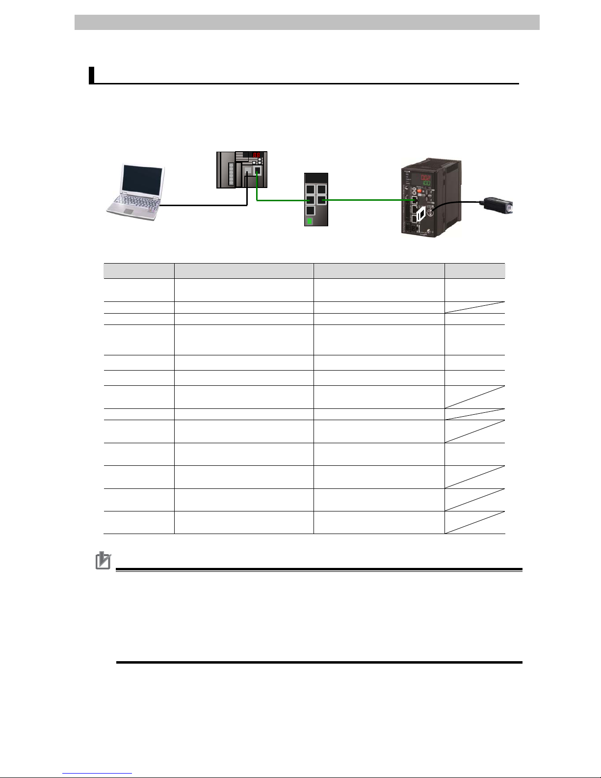
5.2. Device Configuration
The hardware components to reproduce the connection procedure of this document are as
follows:
CJ2M-CPU32
(Built-in EtherNet/IP port)
Personal computer
(CX-One installed)
OS: Windows 7
USB cable
Switching Hub
(W4S1-05C)
ZW-S40
Ethernet
cable
Calibration ROM
ZW-CE10
Manufacturer Name Model Version
OMRON CPU Unit
(Built-in EtherNet/IP port)
CJ2M-CPU32
(with built-in CJ2M-EIP21)
Ver.2.0
(Ver.2.1)
OMRON Power Supply Unit CJ1W-PA202
OMRON Switching Hub W4S1-05C Ver.1.0
OMRON CX-One
CXONE-AL[][]C-V4
/AL[][]D-V4
Ver.4.[][]
OMRON CX-Programmer
(Included in CX-One.)
Ver.9.41
OMRON Network Configurator
(Included in CX-One.)
Ver.3.55
- Personal computer
(OS: Windows 7)
-
- USB cable -
OMRON Ethernet cable (with industrial
Ethernet connector)
XS5W-T421-[]M[]-K
OMRON Displacement Sensor
Controller
ZW-CE10 Ver.1.110
OMRON Displacement Sensor
Sensor Head
ZW-S40
OMRON
Calibration ROM (Included with Sensor
Head.)
OMRON
Recommended power supply:
24VDC 2.5A 60W
S8VS-06024
Precautions for Correct Use
Update the CX-Programmer and Network Configurator to the versions specified in this
section or higher versions using the auto update function.
If a version not specified in this section is used, the procedures described in Section 6 and
subsequent sections may not be applicable. In that case, use the equivalent procedures
described in the CX-Programmer Operation Manual (Cat. No. W446) and Network
Configurator Online Help.
7

5. Applicable Devices and Support Software
Additional Information
The system configuration in this document uses USB for the connection between the
personal computer and PLC. When installing the USB driver, please refer to A-5 Installing the
USB Driver in the CJ-series CJ2 CPU Unit Hardware User's Manual (Cat. No. W472).
8

6. EtherNet/IP Connection Procedure
9
6. EtherNet/IP Connection Procedure
This section explains the procedure for connecting the Displacement Sensor to the PLC via
EtherNet/IP.
6.1. EtherNet/IP Communications Settings
The settings shown in the table below are used to explain the procedure for connecting the
PLC.
This document explains the procedure for setting up the PLC and Displacement Sensor from
the factory default setting. For the initialization, refer to Section 7 Initialization Method.
6.1.1. Settings
The settings of the PLC (EtherNet/IP Unit) and the Displacement Sensor are as follows:
PLC (EtherNet/IP Unit)
(node 1)
Displacement Sensor
(node 2)
Unit number 0 -
Node address 1 2
IP address 192.168.250.1 192.168.250.2
Subnet mask 255.255.255.0 255.255.255.0 (default)
MEMLNK
(Memory link function)
- EIP (EtherNet/IP)
6. EtherNet/IP Connection Procedure
10
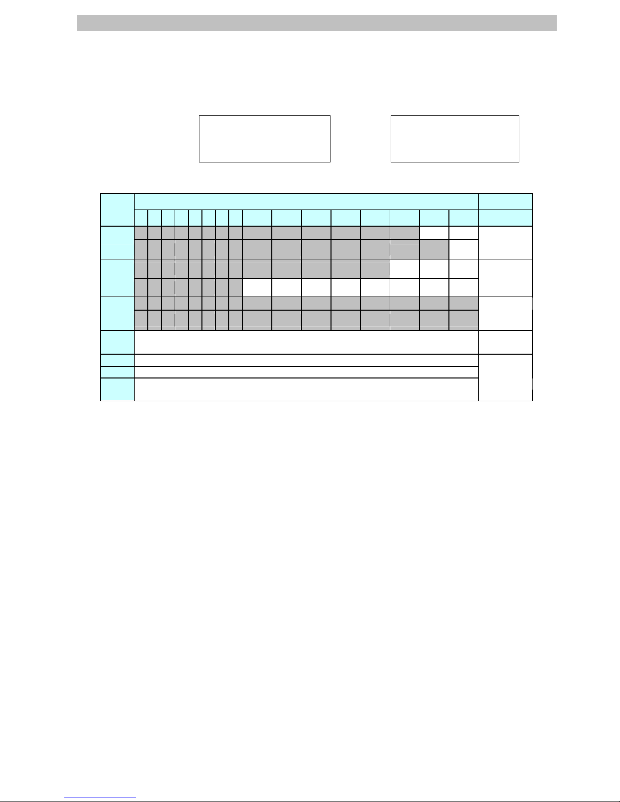
6.1.2. Tag Data Link Allocation
The tag data link allocation of the Displacement Sensor is as follows:
Output area Input area
D10000
D10011
(PLC → Displacement
Sensor)
24 bytes
D10100
D10127
(Displacement Sensor →
PLC)
56 bytes
•Output area (PLC → Displacement Sensor)
Bit
15 14 13 12 11 10 9 8 7 6 5 4 3 2 1 0
Description
D10000
SYNC EXE
D10001
ERCLR
Control
input
*1
(2 words)
D10002
LIGHT
OFF
RESET1 TMNG1
D10003
ZERO
CLR_T4
ZERO
CLR_T3
ZERO
CLR_T2
ZERO
CLR_T1
ZERO1
_T4
ZERO1
_T3
ZERO1
_T2
ZERO1
_T1
Control
input
*2
(2 words)
D10004
D10005
Control
input
*3
(2 words)
D10006
D10007
Command code (2 words) -
D10008
Command parameter 1 Command
D10009
Command parameter 2 parameters
D10010
D10011
Command parameter 3
(Up to 4
words)
*1: Sensor head common control signal
*2: Sensor head 1 control signal
*3: Sensor head 2 control signal (Reserved)
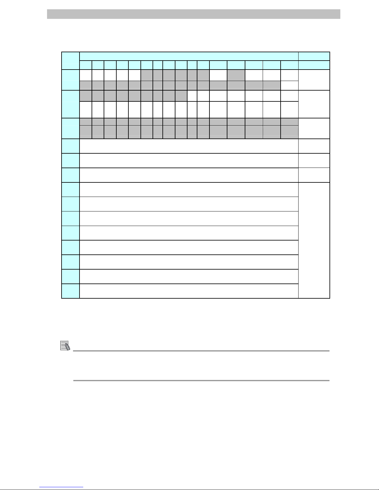
6. EtherNet/IP Connection Procedure
•Input area (
Displacement Sensor → PLC)
Bit
15 14 13 12 11 10 9 8 7 6 5 4 3 2 1 0 Description
D10100
BANK
1_E
BANK
1_D
BANK
1_C
BANK
1_B
BANK
1_A
RUN READY
SYNC
FLG
FLG
D10101
ERR
Control
output
*1
(2 words)
D10102
OR1
GATE
1
ENABLE1
STABLIT
Y1
LIGHT1
RESETS
TAT1
HOLDST
AT1
D10103
LOW1
_T4
PASS
1
_T4
HIGH
1_T4
LOW1
_T3
PASS
1
_T3
HIGH
1_T3
LOW
1_T2
PASS
1
_T2
HIGH
1_T2
LOW
1_T1
PASS
1
_T1
HIGH1_T1 ZEROST
AT_T4
ZEROST
AT_T3
ZEROST
AT_T2
ZEROST
AT_T1
Control
output
*2
(2 words)
D10104
D10105
Control
output
*3
(2 words)
D10106
D10107
Command code (2 words)
-
D10108
D10109
Response code (2 words)
-
D10110
D10111
Response data (2 words)
-
D10112
D10113
Output data 0
D10114
D10115
Output data 1
D10116
D10117
Output data 2
D10118
D10119
Output data 3
D10120
D10121
Output data 4
D10122
D10123
Output data 5
D10124
D10125
Output data 6
D10126
D10127
Output data 7
Output data
(16 words)
*1: Sensor head common status signal
*2: Sensor head 1 status signal
*3: Sensor head 2 status signal (Reserved)
Additional Information
For details on the command codes and response codes, refer to 6-3 Ethernet/IP Connection
under Chapter 6 Communications with External Devices in the ZW Series Displacement
Sensor (Confocal Fiber Type) User's Manual (Cat. No. Z332).
11

6. EtherNet/IP Connection Procedure
12
6.2. Work Flow
Take the following steps to set the tag data link for EtherNet/IP.
6.3 Setting Up the Displacement Sensor Set up the Displacement Sensor.
↓
6.3.1 Parameter Settings Set the parameters for the Displacement Sensor.
↓
6.4 Setting Up the PLC Set up the PLC.
↓
6.4.1 Hardware Settings Set the hardware switches on the EtherNet/IP Unit.
↓
6.4.2 Starting the CX-Programmer and
Connecting Online with PLC
Start the CX-Programmer and connect online with
the PLC.
↓
6.4.3 Creating the I/O Table and
Setting the IP Address
Create the I/O table for the PLC and set the IP
address.
↓
6.4.4 Starting the Network Configurator
and Uploading the Configuration
Start the Network Configurator and upload the
network configuration.
↓
6.4.5 Setting Tags Register the tags of the send area and receive area.
↓
6.4.6 Setting Connections
Associate the tags of the target device with the tags
of the originator.
↓
6.4.7. Transferring the Tag Data Link
Parameters
Transfer the set tag data link parameters to the PLC.
↓
6.5 Checking the EtherNet/IP
Communications
Confirm that the EtherNet/IP communications are
performed normally.
↓
6.5.1 Checking the Connection Status Check the connection status of EtheNet/IP.
↓
6.5.2 Checking Data that are Sent and
Received
Confirm that correct data are sent and received.
6. EtherNet/IP Connection Procedure
6.3. Setting Up the Displacement Sensor
Set up the Displacement Sensor.
6.3.1. Parameter Settings
Set the parameters for the Displacement Sensor.
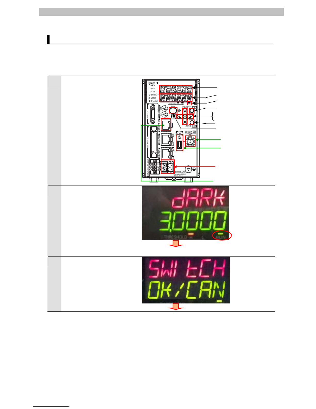
1
Check the keys and display
used to set parameters for the
Displacement Sensor.
Connect the Controller to the
Sensor Head and connect the
Calibration ROM.
Connect the Ethernet cable.
Turn ON the power supply to the
Displacement Sensor.
2
After the startup screen is
displayed, the RUN mode
screen is displayed.
The RUN indicator is lit as
shown on the right.
Hold down the Mode switching
Key for two seconds.
Hold down the Mode switching
Key for two seconds.
3
A confirmation screen for mode
switching is displayed.
Press the ZERO/SET Key.
Press the ZERO/SET Key once.
Ethernet cable
24V power supply
Main display (red)
Sub-display (green)
RUN indicator (green)
Sensor Head
Calibration ROM
ZERORST/ESC key
← (LEFT) Key ↑ (UP) Key
→ (RIGHT) Key ↓ (DOWN) Key
ZERO/SET Key
Mode switching Key
13
6. EtherNet/IP Connection Procedure
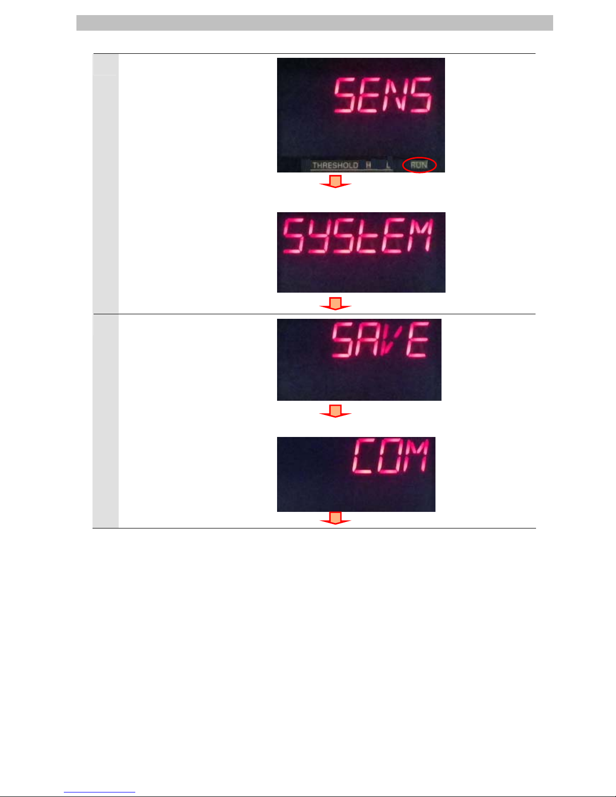
4
The RUN mode screen is
displayed.
The RUN indicator is not lit as
shown on the right.
Press → (RIGHT) Key or ←
(LEFT) Key to change the main
display content from SENS to
SYSTEM.
Press the ZERO/SET Key.
Press the → (RIGHT) Key or ← (LEFT)
Key.
Press the ZERO/SET Key once.
5
SAVE is displayed on the main
display.
Press → (RIGHT) Key or ←
(LEFT) Key and change the
main display content from SAVE
to COM.
Press the ZERO/SET Key.
Press the → (RIGHT) Key or ← (LEFT)
Key.
Press the ZERO/SET Key once.
14
 Loading...