

Omron ZW-C1*T User Manual

Displacement Sensor
ZW series
Confocal Fiber Type
Displacement Sensor
User’s Manual
ZW-C1@ T
Z322-E1-05

Introduction
Thank you for purchasing the ZW.
This manual provides information regarding functions, performance and operating methods that
are required for using the ZW.
When using the ZW, be sure to observe the following:
• The ZW must be operated by personnel knowledgeable in electrical engineering.
• To ensure correct use, please read this manual thoroughly to deepen your understanding of the
product.
• Please keep this manual in a safe place so that it can be referred to whenever necessary.

APPLICATION CONSIDERATIONS
(Please Read)
User's Manual
Basic configuration
Installation and Connections
Basic Operation
Settings for Function
Convenient Functions
Communications with External Devices
1
2
3
4
5
6
Confocal Fiber Type
Displacement Sensor
ZW
Offline Settings
Troubleshooting
Sensor controller operations
APPENDICES
7
8
9
10

APPLICATION CONSIDERATIONS (Please Read)
READ AND UNDERSTAND THIS DOCUMENT
Please read and understand this document before using the products. Please consult your OMRON
representative if you have any questions or comments.
WARRANTY
OMRON’s exclusive warranty is that the products are free from defects in materials and workmanship for a
period of one year (or other period if specified) from date of sale by OMRON.
OMRON MAKES NO WARRANTY OR REPRESENTATION, EXPRESS OR IMPLIED, REGARDING NONINFRINGEMENT, MERCHANTABILITY, OR FITNESS FOR PARTICULAR PURPOSE OF THE PRODUCTS.
ANY BUYER OR USER ACKNOWLEDGES THAT THE BUYER OR USER ALONE HAS DETERMINED THAT
THE PRODUCTS WILL SUITABLY MEET THE REQUIREMENTS OF THEIR INTENDED USE. OMRON
DISCLAIMS ALL OTHER WARRANTIES, EXPRESS OR IMPLIED.
LIMITATIONS OF LIABILITY
OMRON SHALL NOT BE RESPONSIBLE FOR SPECIAL, INDIRECT, OR CONSEQUENTIAL DAMAGES,
LOSS OF PROFITS OR COMMERCIAL LOSS IN ANY WAY CONNECTED WITH THE PRODUCTS,
WHETHER SUCH CLAIM IS BASED ON CONTRACT, WARRANTY, NEGLIGENCE, OR STRICT LIABILITY.
In no event shall responsibility of OMRON for any act exceed the individual price of the product on which
liability is asserted.
IN NO EVENT SHALL OMRON BE RESPONSIBLE FOR WARRANTY, REPAIR, OR OTHER CLAIMS
REGARDING THE PRODUCTS UNLESS OMRON’S ANALYSIS CONFIRMS THAT THE PRODUCTS WERE
PROPERLY HANDLED, STORED, INSTALLED, AND MAINTAINED AND NOT SUBJECT TO
CONTAMINATION, ABUSE, MISUSE, OR INAPPROPRIATE MODIFICATION OR REPAIR.
SUITABILITY FOR USE
THE PRODUCTS CONTAINED IN THIS DOCUMENT ARE NOT SAFETY RATED. THEY ARE NOT DESIGNED OR
RATED FOR ENSURING SAFETY OF PERSONS, AND SHOULD NOT BE RELIED UPON AS A SAFETY
COMPONENT OR PROTECTIVE DEVICE FOR SUCH PURPOSES.
Please refer to separate catalogs for OMRON’s safety rated products.
OMRON shall not be responsible for conformity with any standards, codes, or regulations that apply to the
combination of products in the customer’s application or use of the product.
At the customer’s request, OMRON will provide applicable third party certification documents identifying ratings
and limitations of use that apply to the products. This information by itself is not sufficient for a complete
determination of the suitability of the products in combination with the end product, machine, system, or other
application or use.
The following are some examples of applications for which particular attention must be given. This is not
intended to be an exhaustive list of all possible uses of the products, nor is it intended to imply that the uses
listed may be suitable for the products:
• Outdoor use, uses involving potential chemical contamination or electrical interference, or conditions or uses
not described in this document.
2
ZW User's Manual

• Nuclear energy control systems, combustion systems, railroad systems, aviation systems, medical
equipment, amusement machines, vehicles, safety equipment, and installations subject to separate industry
or government regulations.
• Systems, machines, and equipment that could present a risk to life or property.
Please know and observe all prohibitions of use applicable to the products.
NEVER USE THE PRODUCTS FOR AN APPLICATION INVOLVING SERIOUS RISK TO LIFE OR
PROPERTY WITHOUT ENSURING THAT THE SYSTEM AS A WHOLE HAS BEEN DESIGNED TO
ADDRESS THE RISKS, AND THAT THE OMRON PRODUCT IS PROPERLY RATED AND INSTALLED FOR
THE INTENDED USE WITHIN THE OVERALL EQUIPMENT OR SYSTEM.
PERFORMANCE DATA
Performance data given in this document is provided as a guide for the user in determining suitability and does
not constitute a warranty. It may represent the result of OMRON’s test conditions, and the users must correlate
it to actual application requirements. Actual performance is subject to the OMRON Warranty and Limitations of
Liability.
CHANGE IN SPECIFICATIONS
Product specifications and accessories may be changed at any time based on improvements and other
reasons.
It is our practice to change model numbers when published ratings or features are changed, or when significant
construction changes are made. However, some specifications of the product may be changed without any
notice. When in doubt, special model numbers may be assigned to fix or establish key specifications for your
application on your request. Please consult with your OMRON representative at any time to confirm actual
specifications of purchased products.
DIMENSIONS AND WEIGHTS
Dimensions and weights are nominal and are not to be used for manufacturing purposes, even when
tolerances are shown.
ERRORS AND OMISSIONS
The information in this document has been carefully checked and is believed to be accurate; however, no
responsibility is assumed for clerical, typographical, or proofreading errors, or omissions.
PROGRAMMABLE PRODUCTS
OMRON shall not be responsible for the user’s programming of a programmable product, or any consequence
thereof.
COPYRIGHT AND COPY PERMISSION
This document shall not be copied for sales or promotions without permission.
This document is protected by copyright and is intended solely for use in conjunction with the product. Please
notify us before copying or reproducing this document in any manner, for any other purpose. If copying or
transmitting this document to another, please copy or transmit it in its entirety.
ZW User's Manual
3

Precautions for Safe Use
Please observe the following precautions for safe use of the products.
1. Installation Environment
• Do not use the product in environments where it can be exposed to inflammable/explosive gas.
• To secure the safety of operation and maintenance, do not install the product close to high-voltage devices
and power devices.
2. Power Supply and Wiring
• Take care when using a power supply with an overcurrent detector, because this sensor uses DC-DC
converter for its power supply circuit and inrush current may activate the protective circuit for a power supply
with an overcurrent detector.
Recommended power supply: S8VS-06024 (Omron, DC24 V 2.5 A 60 W)
• The supply voltage must be within the rated range (DC24 V ± 10 %).
• Reverse connection of the power supply is not allowed.
• Open-collector outputs should not be short-circuited.
• Use the power supply within the rated load.
• High-voltage lines and power lines must be wired separately from this product. Wiring them together or
placing them in the same duct may cause induction, resulting in malfunction or damage.
• Use adequate safety measures, for example fail-safe circuits.
• Use a specified-sized wire when wiring. Do not connect wires other than those of the specification to the
terminal block.
• For a power supply, use a DC power supply unit provided with a remedy, for example, safety ultralow voltage
circuit, to prevent a high voltage from being generated.
• Route so that power supply wires are as short as possible.
• Use a power supply dedicated for this product, without sharing it with other products.
• Tighten fixing screws securely at a torque specified in this manual.
• Before performing any of the following activities, be sure to turn off the product, or breakdown may result.
- Connecting or wiring cables
- Connecting or disconnecting connectors
- Installing or removing Calibration ROM
3. Grounding
• Use a frame ground terminal of the specified size to be grounded. Do not connect a wire with an only twisted
end directly to a terminal block.
- Terminal screw: M4
- Crimp-type terminal:
8.5mm
or less
• Use D-type grounding (ground resistance of 100 or less). Make the ground point as close as possible and
make the ground wire used as short as possible.
• Never a ground wire with other equipment and never ground to building beams. Doing so could cause
negative impacts.
• The power supply circuit of the Sensor Controller is not insulated from the internal circuits.
• When grounding the positive (+) terminal of the 24 VDC power supply, do not connect the Sensor Controller's
frame ground terminal or PLC's frame ground terminal to ground. [(1), (2)]
The PC housing may be internally connected to the SG (0 V), in which case current will flow through the path
shown below and may cause seizure.
4
8.5mm
or less
ZW User's Manual
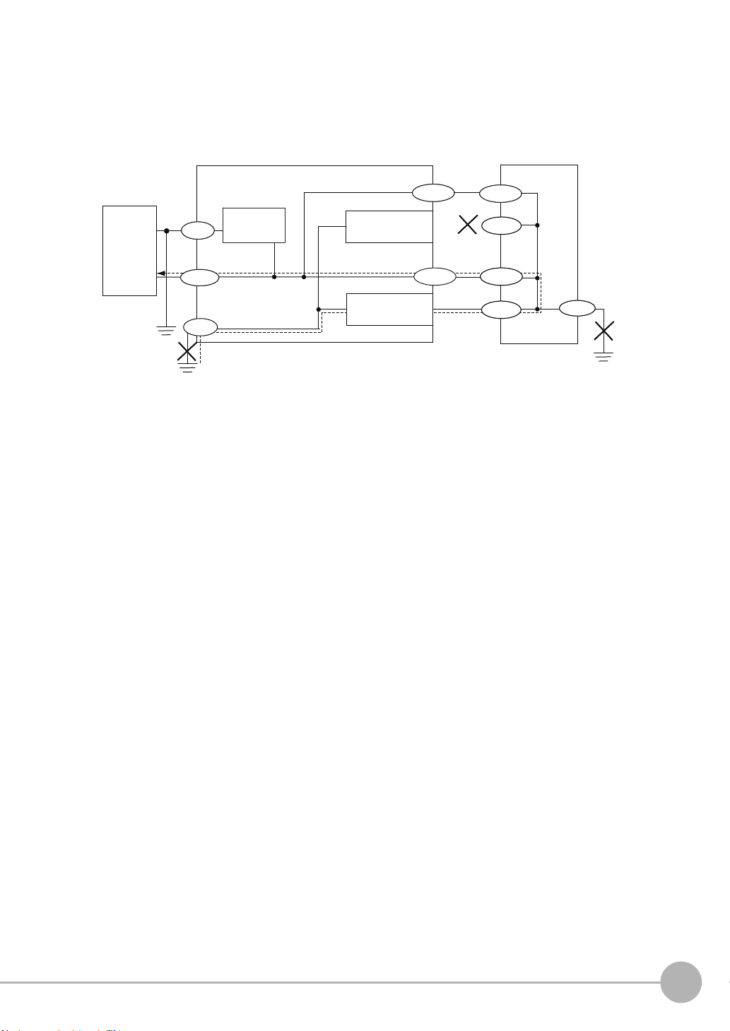
• If there is no PC, or specifically there is no SG (0 V)/FG short-circuiting path, grounding the Sensor
24V
FG
SG
FG
SG
FG
SG
FG
SG
SG
24 V DC
power
supply
Sensor Controller
24V
PC or PLC
SG: Signal Ground (0 V for 24 V DC power supply)
FG: Frame Ground
FG
(1)
(2)
SG
FG
SG
FG
SG
SG
Power supply
circuit
(3)
RS-232C
connector housing
RS-232C
Ethernet
connector housing
Ethernet
SG
FG
Controller's frame ground terminal will not cause seizure. Wire the PLC after checking the specification of
your PLC.
• The dedicated RS-232C cable (ZW-XRS2/XPT2) has its cable shield isolated from the connector housing.
[(3)]
4. Regulations and Standards
• EN61326-1
• Electromagnetic environment : Industrial electromagnetic environment (EN/IEC 61326-1 Table 2)
• The following condition is applied to the immunity test of this product:
There may be cases that current or voltage output fluctuate within ± 3%F.S. when a sensor is experienced
electromagnetic interference.
• Notice for Korea Radio Law
A급 기기 (업무용 방송통신기자재)
이 기기는 업무용 ( A급 ) 전자파적합기기로서 판매자
또는 사용자는 이 점을 주의하시기 바라며 , 가정외의
지역에서 사용하는 것을 목적으로 합니다.
5. Others
• Do not use this product for nuclear facilities, or safety circuits involving human lives.
• Do not attempt to disassemble, repair, modify, apply pressure to deform or burn up the body.
• Dispose of this product as industrial waste.
• Use exclusive devices, including a sensor head, Calibration ROM, fiber cable or RS-232C cable, to connect,
or ignition, burst, false operation or breakdown may be caused.
• Do not cut fiber cable. Glass at the cut section may cause injury. Also, if cut, it will not work normally
anymore.
• Whenever any trouble, including, strange odor smelled, the body overheated or smoke escaped, was found,
immediately stop the operation, and consult an OMRON branch or sales office with the system shut down.
• Do not drop or make a strong impact on the unit.
• Before using any equipment provided with a lock mechanism, make sure that it has been locked.
ZW User's Manual
5

Precautions for Correct Use
Please observe the following precautions to prevent failure to operate, malfunctions, or undesirable effects on
product performance.
1. Installation Site
Do not install the product in locations subjected to the following conditions:
• Ambient temperature outside the rating
• Rapid temperature fluctuations (causing condensation)
• Relative humidity outside the range of 35 to 85 %
• Presence of corrosive or flammable gases
• Presence of dust, salt, or iron particles
• Direct vibration or shock
• Reflection of intense light (such as other laser beams, electric arc-welding machines or ultraviolet shine)
• Direct sunlight or near heaters
• Water, oil, or chemical fumes, spray or mist atmospherics
• Strong magnetic or electric field
2. Power Supply and Wiring
• When using a commercially available switching regulator, make sure that the FG terminal is grounded.
• If surge currents are present in the power lines, connect surge absorbers that suit the operating environment.
• Before turning ON the power after the product is connected, make sure that the power supply voltage is
correct, there are no incorrect connections (e.g. load short-circuit) and the load current is appropriate.
Incorrect wiring may result in breakdown of the product.
• Use the specified voltage. If voltage exceeding the rating or AC voltage is applied, circuit parts may be burnt
or rupture.
• Use the Extension Fiber Cable (ZW-XF@@R) for extending the fiber cable between the Sensor extension
fiber cable, five total lengths, 2, 5, 10, 20 or 30 m, are available.
• Handling fiber cables
Use them in compliance with the following. This may result in damage to the fiber cable.
-Fiber cable bend radiuses must be at least 20 mm.
- Do not let bending cause stress at the root section of a fiber connector.
- Do not yank hard on a fiber cable.
- Do not step on a fiber cable or place anything heavy on it.
- Do not apply any twisting stress to the fiber cable.
• Be sure to use a Sensor Head and Calibration ROM with the same serial number. A pair with different serial
numbers cannot operate normally.
• Use the configuration software with the combination specified in this manual, or the system may operate
faultily.
• Do not shut down the power supply when saving any data into the memory built in the Sensor Controller, or
the data may be corrupted.
• While a fiber cable is disconnected, be sure to attach the included protective cap on both the Sensor
Controller side and the fiber cable side. Leaving the fiber cable with the protective cap not attached, the
optical fiber may fail due to any adhered foreign matter.
3. Warming Up
After turning ON the power supply, allow the product to stand for at least 30 minutes before use. The circuits
are still unstable immediately after the power supply is turned ON, so measured values may fluctuate gradually.
6
ZW User's Manual

4. Maintenance and Inspection
Important
Note
Optional
Do not use thinner, benzene, acetone or kerosene to clean the Sensor Head, fiber cable and Sensor Controller.
If large dust particles adhere to the emitter/receiver of the Sensor Head or Sensor Controller, use a blower
brush (used to clean camera lenses) to blow them off. Do not blow the dust particles with your mouth.
To remove smaller dust particles, dirt, oil, and fat, wipe gently with a soft cloth (for cleaning lenses). Do not use
excessive force to wipe off dust particles. Scratches on the emitter/receiver may cause false operations or
measuring errors.
For details on the method for cleaning the ends of fiber cables, refer to "Connecting Fiber Cable" (p.34).
Clean the ventilation port periodically to prevent any build up of dirt and dust. If the ventilation port is blocked,
heat builds up inside and can cause breakdown.
5. Sensing Objects
The product sometimes cannot accurately measure the following types of objects: Transparent objects, objects
with an extremely low reflection factor, objects smaller than the spot diameter, objects with a large curvature,
excessively inclined objects, target objects with a thin film on the surface etc.
6. Effect caused by peripheral lights
Do not install the Sensor Head in a place where strong light hits the laser emitter/receiver section of the Sensor
Head. Also, if an object has a shiny surface, the light from the lighting will be reflected and a malfunction may
occur. In such a case, prevent reflection by, for example, covering the light to stop reflection.
Basic precautions for installation p.26
7. Influence by Air Turbulences
Slow air turbulences around the Sensor Head may disperse measured values.
To avoid these possible air turbulences, wrap the Sensor Head with an appropriate cover.
8. Operations Outside Measurement Range
This sensor is highly sensitive, it may operate incorrectly outside the measurement range (too close in). In such
a case, the problem can be solved by reducing the exposure time.
Editor's Note
■ Meaning of Symbols
Menu items that are displayed on the main or sub-display, and windows, dialog boxes and other GUI elements
displayed on the personal computer are indicated enclosed by brackets [ ].
■ Visual Aids
Indicates points that are important to achieve the full product performance, such as operational
precautions.
Indicates application procedures.
Indicates pages where related information can be found.
Indicates that the setting is optional in a configuration procedure.
ZW User's Manual
7

Copyrights and Trademarks
• Windows, Windows XP, Windows Vista, Windows 7, and Windows 8 are registered trademarks of Microsoft
Corporation in the USA and other countries.
• Other system names and product names that appear in this manual are the trademarks or registered trademarks of
the respective companies.
Notice
• Photocopying, duplication, or copying of all or part of this manual without permission is prohibited.
• Please understand that the specifications and other contents of this manual are subject to change for improvement
without notice.
• Every effort has been made to ensure the accuracy of the contents of this manual, but if you should notice any
mistake, questionable section, or the like in this manual, please contact an OMRON branch or sales office.
• If you do so, please also tell us the manual number, which is found at the end of the manual.
8
ZW User's Manual

Table of Contents
Editor's Note . . . . . . . . . . . . . . . . . . . . . . . . . . . . . . . . . . . . . . . . . . . . . . . . . . . . 7
Copyrights and Trademarks . . . . . . . . . . . . . . . . . . . . . . . . . . . . . . . . . . . . . . . .8
Notice . . . . . . . . . . . . . . . . . . . . . . . . . . . . . . . . . . . . . . . . . . . . . . . . . . . . . . . . . 8
Search from Settings . . . . . . . . . . . . . . . . . . . . . . . . . . . . . . . . . . . . . . . . . 14
1.Basic configuration
1-1 ZW-series Displacement Sensors . . . . . . . . . . . . . . . . . . . . . . . . . . . . 16
Types of Sensor Controllers . . . . . . . . . . . . . . . . . . . . . . . . . . . . . . . . . . . . . . . 16
1-2 Basic Operation Flow . . . . . . . . . . . . . . . . . . . . . . . . . . . . . . . . . . . . . . 17
2.Installation and Connections
2-1 System Configuration. . . . . . . . . . . . . . . . . . . . . . . . . . . . . . . . . . . . . . 20
System Configuration . . . . . . . . . . . . . . . . . . . . . . . . . . . . . . . . . . . . . . . . . . . . 20
Connection Compatibility . . . . . . . . . . . . . . . . . . . . . . . . . . . . . . . . . . . . . . . . . . 21
2-2 Part Names and Functions. . . . . . . . . . . . . . . . . . . . . . . . . . . . . . . . . . 22
Sensor Head . . . . . . . . . . . . . . . . . . . . . . . . . . . . . . . . . . . . . . . . . . . . . . . . . . . 22
Calibration ROM . . . . . . . . . . . . . . . . . . . . . . . . . . . . . . . . . . . . . . . . . . . . . . . . 22
Sensor Controller . . . . . . . . . . . . . . . . . . . . . . . . . . . . . . . . . . . . . . . . . . . . . . . 23
2-3 Installation . . . . . . . . . . . . . . . . . . . . . . . . . . . . . . . . . . . . . . . . . . . . . . . 26
Installation of Sensor Head . . . . . . . . . . . . . . . . . . . . . . . . . . . . . . . . . . . . . . . . 26
Installation of Sensor Controller . . . . . . . . . . . . . . . . . . . . . . . . . . . . . . . . . . . . 31
Connecting Calibration ROM . . . . . . . . . . . . . . . . . . . . . . . . . . . . . . . . . . . . . . . 33
Connecting Fiber Cable . . . . . . . . . . . . . . . . . . . . . . . . . . . . . . . . . . . . . . . . . . . 34
Calibrating Sensor Head . . . . . . . . . . . . . . . . . . . . . . . . . . . . . . . . . . . . . . . . . . 38
2-4 Wiring . . . . . . . . . . . . . . . . . . . . . . . . . . . . . . . . . . . . . . . . . . . . . . . . . . . 40
20-pole terminal block . . . . . . . . . . . . . . . . . . . . . . . . . . . . . . . . . . . . . . . . . . . . 40
52-pole extension connector . . . . . . . . . . . . . . . . . . . . . . . . . . . . . . . . . . . . . . . 43
Electrical Specifications . . . . . . . . . . . . . . . . . . . . . . . . . . . . . . . . . . . . . . . . . . . 46
2-5 Installing the Sysmac Studio . . . . . . . . . . . . . . . . . . . . . . . . . . . . . . . . 48
Table of Contents
3.Basic Operation
3-1 Launching a project . . . . . . . . . . . . . . . . . . . . . . . . . . . . . . . . . . . . . . . 50
Connecting to the sensor with PC tool . . . . . . . . . . . . . . . . . . . . . . . . . . . . . . . 50
Entering project information . . . . . . . . . . . . . . . . . . . . . . . . . . . . . . . . . . . . . . . 51
3-2 Explanation of Screen Sections . . . . . . . . . . . . . . . . . . . . . . . . . . . . . 52
ZW User's Manual
9

PC tool . . . . . . . . . . . . . . . . . . . . . . . . . . . . . . . . . . . . . . . . . . . . . . . . . . . . . . . . 52
3-3 Switching operation modes . . . . . . . . . . . . . . . . . . . . . . . . . . . . . . . . . 57
3-4 Bank switching . . . . . . . . . . . . . . . . . . . . . . . . . . . . . . . . . . . . . . . . . . . 58
Multi-task and Bank Data . . . . . . . . . . . . . . . . . . . . . . . . . . . . . . . . . . . . . . . . . 58
Switching Banks . . . . . . . . . . . . . . . . . . . . . . . . . . . . . . . . . . . . . . . . . . . . . . . . 60
3-5 Perform the Zero Reset . . . . . . . . . . . . . . . . . . . . . . . . . . . . . . . . . . . . 61
Zero reset . . . . . . . . . . . . . . . . . . . . . . . . . . . . . . . . . . . . . . . . . . . . . . . . . . . . . 61
3-6 Setting Threshold Value. . . . . . . . . . . . . . . . . . . . . . . . . . . . . . . . . . . . 64
Threshold Value Settings . . . . . . . . . . . . . . . . . . . . . . . . . . . . . . . . . . . . . . . . . 64
3-7 Saving a project . . . . . . . . . . . . . . . . . . . . . . . . . . . . . . . . . . . . . . . . . . 66
Saving a project . . . . . . . . . . . . . . . . . . . . . . . . . . . . . . . . . . . . . . . . . . . . . . . . . 66
Exporting a project . . . . . . . . . . . . . . . . . . . . . . . . . . . . . . . . . . . . . . . . . . . . . . 66
Importing a project . . . . . . . . . . . . . . . . . . . . . . . . . . . . . . . . . . . . . . . . . . . . . . . 66
3-8 Operating with Sensor Controller . . . . . . . . . . . . . . . . . . . . . . . . . . . . 67
4.Settings for Function
4-1 Setting Sensing. . . . . . . . . . . . . . . . . . . . . . . . . . . . . . . . . . . . . . . . . . . 70
Selecting the Area Mode . . . . . . . . . . . . . . . . . . . . . . . . . . . . . . . . . . . . . . . . . . 70
Setting the Material of the Target to Measure . . . . . . . . . . . . . . . . . . . . . . . . . . 71
Setting the Noise Cut Level . . . . . . . . . . . . . . . . . . . . . . . . . . . . . . . . . . . . . . . . 72
Setting Smoothing Size . . . . . . . . . . . . . . . . . . . . . . . . . . . . . . . . . . . . . . . . . . . 73
Setting Start Direction of Count Measurement Surfaces . . . . . . . . . . . . . . . . . .74
Setting Exposure Time Control Mode . . . . . . . . . . . . . . . . . . . . . . . . . . . . . . . . 75
Setting the Measurement Area . . . . . . . . . . . . . . . . . . . . . . . . . . . . . . . . . . . . . 76
4-2 Setting Measurement Items . . . . . . . . . . . . . . . . . . . . . . . . . . . . . . . . . 79
What is a Measurement Item? . . . . . . . . . . . . . . . . . . . . . . . . . . . . . . . . . . . . . 79
Measuring the Height . . . . . . . . . . . . . . . . . . . . . . . . . . . . . . . . . . . . . . . . . . . . 79
Measuring the Thickness . . . . . . . . . . . . . . . . . . . . . . . . . . . . . . . . . . . . . . . . . 81
Performing Calculations . . . . . . . . . . . . . . . . . . . . . . . . . . . . . . . . . . . . . . . . . . 82
4-3 Setting the Output Conditions. . . . . . . . . . . . . . . . . . . . . . . . . . . . . . . 83
Setting Scaling . . . . . . . . . . . . . . . . . . . . . . . . . . . . . . . . . . . . . . . . . . . . . . . . . 83
Setting Filters . . . . . . . . . . . . . . . . . . . . . . . . . . . . . . . . . . . . . . . . . . . . . . . . . . 89
Setting Hold . . . . . . . . . . . . . . . . . . . . . . . . . . . . . . . . . . . . . . . . . . . . . . . . . . . . 94
Setting the Zero Reset . . . . . . . . . . . . . . . . . . . . . . . . . . . . . . . . . . . . . . . . . . 101
4-4 Setting the Banks . . . . . . . . . . . . . . . . . . . . . . . . . . . . . . . . . . . . . . . . 106
Changing the Bank Mode . . . . . . . . . . . . . . . . . . . . . . . . . . . . . . . . . . . . . . . . 106
Copying the Bank/System Settings . . . . . . . . . . . . . . . . . . . . . . . . . . . . . . . . . 107
Saving the Bank/System Settings . . . . . . . . . . . . . . . . . . . . . . . . . . . . . . . . . . 108
Clearing the Bank Settings . . . . . . . . . . . . . . . . . . . . . . . . . . . . . . . . . . . . . . . 109
4-5 Setting the System . . . . . . . . . . . . . . . . . . . . . . . . . . . . . . . . . . . . . . . 110
Checking Information . . . . . . . . . . . . . . . . . . . . . . . . . . . . . . . . . . . . . . . . . . . 110
Making Sensor Settings . . . . . . . . . . . . . . . . . . . . . . . . . . . . . . . . . . . . . . . . . 111
10
ZW User's Manual

Initializing Settings . . . . . . . . . . . . . . . . . . . . . . . . . . . . . . . . . . . . . . . . . . . . . . 112
5.Convenient Functions
5-1 Displaying measured values in graphs. . . . . . . . . . . . . . . . . . . . . . . 116
Specifying the sampling start and end conditions . . . . . . . . . . . . . . . . . . . . . . 118
Starting and ending sampling before and after the trigger condition is met . . 120
5-2 Saving measured values in a file. . . . . . . . . . . . . . . . . . . . . . . . . . . . 121
Outputting the results of sampling as a file . . . . . . . . . . . . . . . . . . . . . . . . . . . 121
Exporting the results of sampling . . . . . . . . . . . . . . . . . . . . . . . . . . . . . . . . . . 121
5-3 Displaying saved measured values. . . . . . . . . . . . . . . . . . . . . . . . . . 124
5-4 Performing internal logging. . . . . . . . . . . . . . . . . . . . . . . . . . . . . . . . 125
5-5 Storing the light reception wave form in a file . . . . . . . . . . . . . . . . . 127
5-6 Recovering calibration ROM data . . . . . . . . . . . . . . . . . . . . . . . . . . . 129
5-7 Printing the contents of settings. . . . . . . . . . . . . . . . . . . . . . . . . . . . 130
5-8 Controll input signal with PC tool . . . . . . . . . . . . . . . . . . . . . . . . . . . 131
6.Communications with External Devices
6-1 Parallel I/O connection . . . . . . . . . . . . . . . . . . . . . . . . . . . . . . . . . . . . 134
I/O Signal Functions . . . . . . . . . . . . . . . . . . . . . . . . . . . . . . . . . . . . . . . . . . . . 134
Settings for Analog Output . . . . . . . . . . . . . . . . . . . . . . . . . . . . . . . . . . . . . . . 138
Settings for Judgment Output . . . . . . . . . . . . . . . . . . . . . . . . . . . . . . . . . . . . .143
Settings for Binary Output . . . . . . . . . . . . . . . . . . . . . . . . . . . . . . . . . . . . . . . . 146
Settings for Processing When Measurement Is Not Possible . . . . . . . . . . . . . 150
Settings for Bank Control . . . . . . . . . . . . . . . . . . . . . . . . . . . . . . . . . . . . . . . . 153
Settings for Internal Logging . . . . . . . . . . . . . . . . . . . . . . . . . . . . . . . . . . . . . .154
Timing Chart . . . . . . . . . . . . . . . . . . . . . . . . . . . . . . . . . . . . . . . . . . . . . . . . . . 155
6-2 No-protocol Connection. . . . . . . . . . . . . . . . . . . . . . . . . . . . . . . . . . . 169
Outline of No-protocol Communications . . . . . . . . . . . . . . . . . . . . . . . . . . . . . 169
Setting Up No-protocol Communications . . . . . . . . . . . . . . . . . . . . . . . . . . . . 170
Setting Communications Specifications (RS-232C Communications) . . . . . . 173
Setting for serial data output after application of measured value . . . . . . . . . 174
Command List . . . . . . . . . . . . . . . . . . . . . . . . . . . . . . . . . . . . . . . . . . . . . . . . . 178
Command Format . . . . . . . . . . . . . . . . . . . . . . . . . . . . . . . . . . . . . . . . . . . . . . 180
Table of Contents
7.Offline Settings
7-1 Performing Settings Offline . . . . . . . . . . . . . . . . . . . . . . . . . . . . . . . . 204
7-2 Starting a Project in Offline Mode . . . . . . . . . . . . . . . . . . . . . . . . . . . 205
7-3 Changing between Online and Offline . . . . . . . . . . . . . . . . . . . . . . . 206
8.Troubleshooting
8-1 Error Messages . . . . . . . . . . . . . . . . . . . . . . . . . . . . . . . . . . . . . . . . . . 208
ZW User's Manual
11

Errors for Ethernet Connection . . . . . . . . . . . . . . . . . . . . . . . . . . . . . . . . . . . .208
Errors Common to All Communication States . . . . . . . . . . . . . . . . . . . . . . . . . 209
8-2 Troubleshooting . . . . . . . . . . . . . . . . . . . . . . . . . . . . . . . . . . . . . . . . . 210
9.Sensor controller operations
9-1 Search from Menu Tree . . . . . . . . . . . . . . . . . . . . . . . . . . . . . . . . . . . 214
FUN Mode Menu . . . . . . . . . . . . . . . . . . . . . . . . . . . . . . . . . . . . . . . . . . . . . . . 214
RUN (run) Mode Menu . . . . . . . . . . . . . . . . . . . . . . . . . . . . . . . . . . . . . . . . . . 219
9-2 Functions of Operating Keys. . . . . . . . . . . . . . . . . . . . . . . . . . . . . . . 220
9-3 Digital Displays . . . . . . . . . . . . . . . . . . . . . . . . . . . . . . . . . . . . . . . . . . 221
9-4 Switching operation modes . . . . . . . . . . . . . . . . . . . . . . . . . . . . . . . . 222
9-5 Functions and Operations during Measurement . . . . . . . . . . . . . . . 224
Switching the RUN (Run) Mode Display . . . . . . . . . . . . . . . . . . . . . . . . . . . . . 224
9-6 Setting Sensing. . . . . . . . . . . . . . . . . . . . . . . . . . . . . . . . . . . . . . . . . . 228
Setting the Material of the Target to Measure . . . . . . . . . . . . . . . . . . . . . . . . . 228
Setting Start Direction of Count Measurement Surfaces . . . . . . . . . . . . . . . . .229
Setting Exposure Time Control Mode . . . . . . . . . . . . . . . . . . . . . . . . . . . . . . . 230
9-7 Setting Measurement Items . . . . . . . . . . . . . . . . . . . . . . . . . . . . . . . . 231
Measuring the Height . . . . . . . . . . . . . . . . . . . . . . . . . . . . . . . . . . . . . . . . . . . 231
Measuring the Thickness . . . . . . . . . . . . . . . . . . . . . . . . . . . . . . . . . . . . . . . . 232
Calculating . . . . . . . . . . . . . . . . . . . . . . . . . . . . . . . . . . . . . . . . . . . . . . . . . . . . 233
9-8 Setting the Output Conditions. . . . . . . . . . . . . . . . . . . . . . . . . . . . . . 236
Setting the Filter . . . . . . . . . . . . . . . . . . . . . . . . . . . . . . . . . . . . . . . . . . . . . . . 236
Setting Scaling . . . . . . . . . . . . . . . . . . . . . . . . . . . . . . . . . . . . . . . . . . . . . . . . 240
Setting Hold . . . . . . . . . . . . . . . . . . . . . . . . . . . . . . . . . . . . . . . . . . . . . . . . . . . 244
Setting the Zero Reset . . . . . . . . . . . . . . . . . . . . . . . . . . . . . . . . . . . . . . . . . . 248
9-9 Setting the Banks . . . . . . . . . . . . . . . . . . . . . . . . . . . . . . . . . . . . . . . . 252
Switching Banks . . . . . . . . . . . . . . . . . . . . . . . . . . . . . . . . . . . . . . . . . . . . . . . 252
Changing the Bank Mode . . . . . . . . . . . . . . . . . . . . . . . . . . . . . . . . . . . . . . . . 253
Copying the Bank Settings . . . . . . . . . . . . . . . . . . . . . . . . . . . . . . . . . . . . . . . 254
Saving the Bank/System Settings . . . . . . . . . . . . . . . . . . . . . . . . . . . . . . . . . . 255
Clearing the Bank Settings . . . . . . . . . . . . . . . . . . . . . . . . . . . . . . . . . . . . . . . 256
9-10 Setting Threshold Value. . . . . . . . . . . . . . . . . . . . . . . . . . . . . . . . . . 257
Teaching . . . . . . . . . . . . . . . . . . . . . . . . . . . . . . . . . . . . . . . . . . . . . . . . . . . . . 257
Direct . . . . . . . . . . . . . . . . . . . . . . . . . . . . . . . . . . . . . . . . . . . . . . . . . . . . . . . . 259
9-11 Setting the System . . . . . . . . . . . . . . . . . . . . . . . . . . . . . . . . . . . . . . 260
Checking Information . . . . . . . . . . . . . . . . . . . . . . . . . . . . . . . . . . . . . . . . . . . 260
Setting the Key Lock . . . . . . . . . . . . . . . . . . . . . . . . . . . . . . . . . . . . . . . . . . . . 261
Calibrating Sensor Head . . . . . . . . . . . . . . . . . . . . . . . . . . . . . . . . . . . . . . . . . 262
Initializing Settings . . . . . . . . . . . . . . . . . . . . . . . . . . . . . . . . . . . . . . . . . . . . . . 263
9-12 Connecting Parallel I/O. . . . . . . . . . . . . . . . . . . . . . . . . . . . . . . . . . . 264
Settings for Analog Output . . . . . . . . . . . . . . . . . . . . . . . . . . . . . . . . . . . . . . . 264
12
ZW User's Manual

Settings for Binary Output . . . . . . . . . . . . . . . . . . . . . . . . . . . . . . . . . . . . . . . . 268
Settings for Judgment Output . . . . . . . . . . . . . . . . . . . . . . . . . . . . . . . . . . . . .271
Settings for Processing When Measurement Is Not Possible . . . . . . . . . . . . . 273
Setting for Internal Logging . . . . . . . . . . . . . . . . . . . . . . . . . . . . . . . . . . . . . . . 275
9-13 Connecting by No-protocol Communications . . . . . . . . . . . . . . . . 277
Initial Settings for No-protocol Communications . . . . . . . . . . . . . . . . . . . . . . . 277
Setting Communications Specifications (RS-232C Communications) . . . . . . 278
Setting Serial Data Output . . . . . . . . . . . . . . . . . . . . . . . . . . . . . . . . . . . . . . . . 279
Set the delimiter . . . . . . . . . . . . . . . . . . . . . . . . . . . . . . . . . . . . . . . . . . . . . . . 280
10.APPENDICES
10-1 Specifications and External Dimensions . . . . . . . . . . . . . . . . . . . . 282
Sensor Head . . . . . . . . . . . . . . . . . . . . . . . . . . . . . . . . . . . . . . . . . . . . . . . . . . 282
Sensor controller . . . . . . . . . . . . . . . . . . . . . . . . . . . . . . . . . . . . . . . . . . . . . . . 294
PC tools (Sysmac Studio) . . . . . . . . . . . . . . . . . . . . . . . . . . . . . . . . . . . . . . . . 298
Accessories . . . . . . . . . . . . . . . . . . . . . . . . . . . . . . . . . . . . . . . . . . . . . . . . . . . 299
EMC Directive Conformity . . . . . . . . . . . . . . . . . . . . . . . . . . . . . . . . . . . . . . . . 303
10-2 Firmware update . . . . . . . . . . . . . . . . . . . . . . . . . . . . . . . . . . . . . . . . 304
Use PC tools (Sysmac Studio) to update. . . . . . . . . . . . . . . . . . . . . . . . . . . . .304
Performing the Update on Warp Engine ZW . . . . . . . . . . . . . . . . . . . . . . . . . . 305
10-3 Processing Item Data List . . . . . . . . . . . . . . . . . . . . . . . . . . . . . . . . 308
10-4 System data list. . . . . . . . . . . . . . . . . . . . . . . . . . . . . . . . . . . . . . . . . 313
Index . . . . . . . . . . . . . . . . . . . . . . . . . . . . . . . . . . . . . . . . . . . . . . . . . . . . . 315
Revision History. . . . . . . . . . . . . . . . . . . . . . . . . . . . . . . . . . . . . . . . . . . . 318
Table of Contents
ZW User's Manual
13

Search from Settings
Settings Set by Sysmac Studio Set by Sensor Controller
Setting the Material for the Target to Measure p.71 p.228
Setting Exposure Time Control Mode p.75 p.230
Measuring the Height p.79 p.231
Measuring the Thickness p.81 p.232
Calculating p.82 p.233
Setting the Filter p.89 p.236
Setting the Scaling p.83 p.240
Setting the Hold p.94 p.244
Setting the Zero Reset p.101 p.248
Changing the Bank Mode p.106 p.253
Copying the Bank/System Settings p.107 p.254
Saving the Bank/System Settings p.108 p.255
Clearing the Bank Settings p.109 p.256
Checking Information p.110 p.260
Setting the Key Lock p.111 p.261
Initializing Settings p.112 p.263
(Bank Settings only)
14
Search from Settings
ZW User's Manual

Basic configuration
1-1 ZW-series Displacement Sensors. . . . . . . . . . . . . . . . . . . . . . . . . . . . . 16
1-2 Basic Operation Flow. . . . . . . . . . . . . . . . . . . . . . . . . . . . . . . . . . . . . . . 17
1
Basic configuration
1-1 ZW-series Displacement Sensors
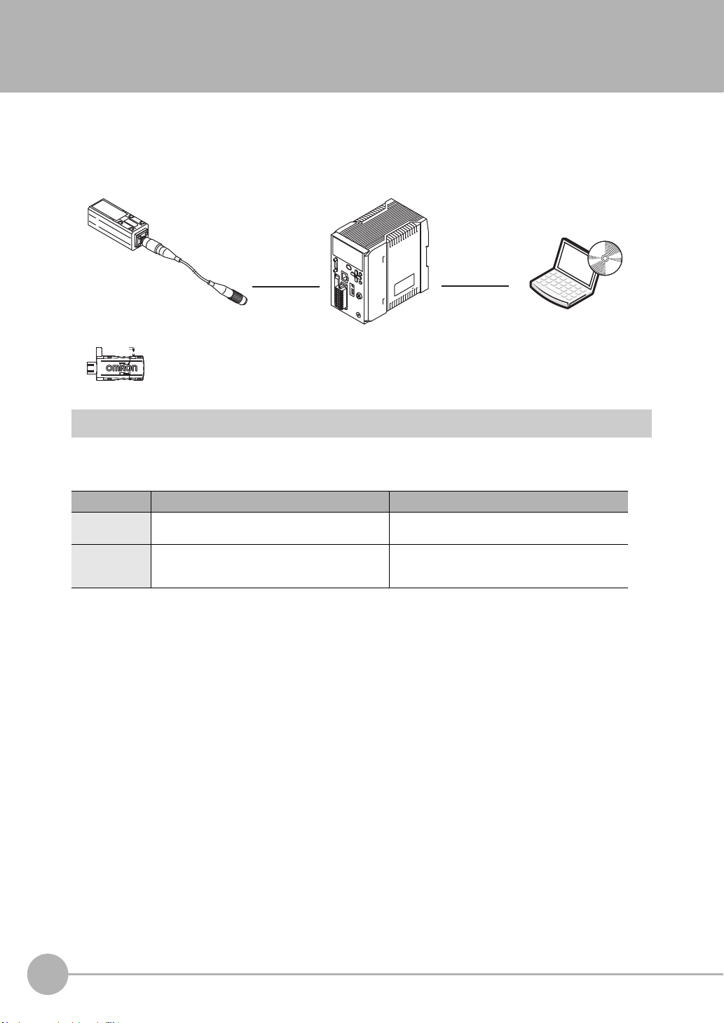
The ZW-series is a line of fiber coaxial displacement sensors.
They consist of Sensor Head and Sensor Controller, calibration ROM, and exclusive setting PC tool which runs
on personal computers for system settings and monitoring.
Sensor head
Detects a target to
measure.
Sensor Controller PC tool
Personal
computer
Calibration ROM
(included with sensor head)
Associated with
the sensor on a
one-to-one basis
Performs measurements
and outputs the result.
Allows making advanced settings
and checking up measured
values easily using exclusive
personal computer software.
Types of Sensor Controllers
The ZW Series has two types of Controllers (hereinafter be referred to as "Sensor Controller" in this
document.). Differences are described below.
Model ZW-C1@T/ZW-C1@AT ZW-CE1@T
I/O
Specifications
PC tool Sysmac Studio (Measurement Sensor Edition)/
EtherCAT and EtherNet/IP not mounted,
Binary output device mounted
Smart MonitorZW version 1.10 or later
EtherCAT and EtherNet/IP mounted,
Binary output device not mounted
Sysmac Studio (Standard Edition)/ Sysmac Studio
(Measurement Sensor Edition)/Smart MonitorZW
version 1.10 or later
16
ZW-series Displacement Sensors
ZW User's Manual

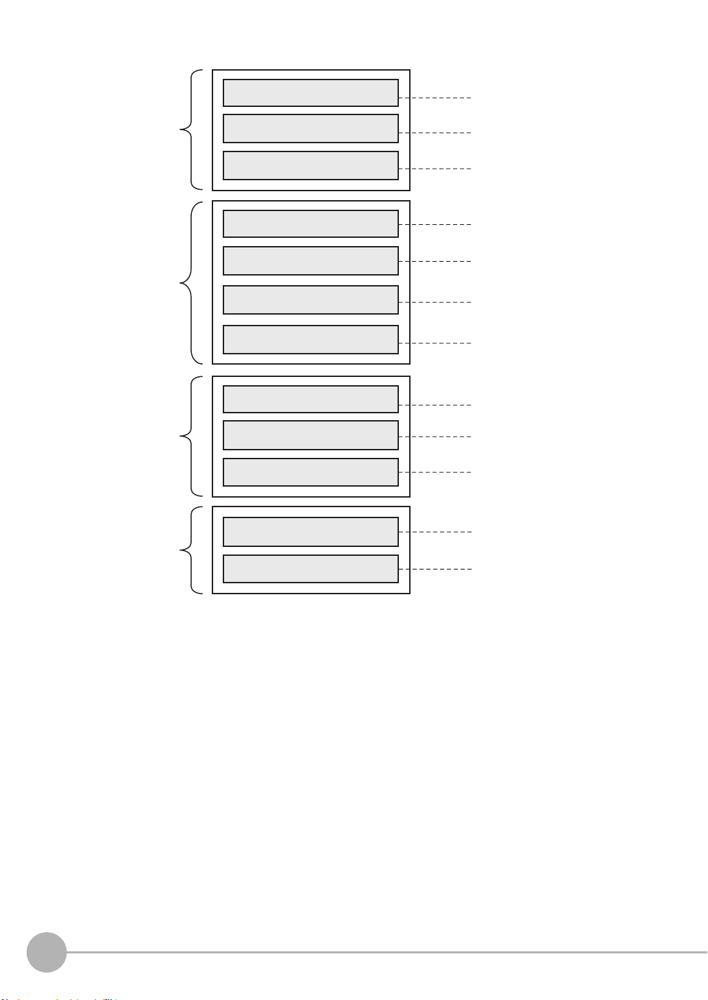
1-2 Basic Operation Flow
Installation and connection
Section 2
4-2
4-3
Preparation
for measurement
Setting
measurement
items
Setting output
processing
Saving settings
Install the sensor head.
Default settings for connecting
the sensor head.
Perform a sensor head calibration.
Setting the scaling
Calibrate the display of the
measured value.
Setting the hold
Set the hold conditions.
Setting the Zero Reset
Set the Zero Reset.
Saving the setting data (*1)
Save the set data.
Setting measurement items
Select task(s) from TASK1 to
TASK4, and set measurement
items, including height, thickness
and calculation.
Setting Measurement Items
Setting the Output Conditions
Installation and Connections
Section 2 Installation and Connections
Section 4 Settings for Functions
Section 4 Settings for Functions
4-3 Setting the Output Conditions
Section 4 Settings for Functions
4-3 Setting the Output Conditions
Section 4 Settings for Functions
3-7 Saving a Project
Section 3 Basic Operation
(*1) After you have made or changed settings,
be sure to save the setup data.
All set data will be cleared if you turn the
power OFF without saving the data.
The following is the basic operation flow for ZW Series.
1
Basic configuration
ZW User's Manual
Basic Operation Flow
17
Functions used
during operation
Operations and
settings according
to need
When having
trouble with setting
When you need
help
Setting Threshold Value
Switching Banks
Executing Zero Reset
Changing Material Settings
Changing Exposure Time Control
Mode Settings
Setting Filter
When an error message is
displayed
When it does not work correctly
Setting I/O (analog/judgment)
Using Ethernet/
RS-232C Communications
Setting the Banks
Setting the System Environment
3-6 Setting Threshold Value
6-1 Parallel I/O connection
6-2 No-protocol Connection
3-4 Bank Switching
3-5 Perform the Zero Reset
Section 3 Basic Operation
Section 6 Communications with
External Devices
4-4
Setting the Banks
4-5
Setting the System
4-2
Setting Measurement Items
4-1
Setting Sensing
4-3
Setting the Output Conditions
Section 4 Settings for Functions
Section 4 Settings for Functions
8-1
Error Messages
8-2
Troubleshooting
Section 8 Troubleshooting
18
Basic Operation Flow
ZW User's Manual

Installation and Connections
2-1 System Configuration . . . . . . . . . . . . . . . . . . . . . . . . . . . . . . . . . . . . . . 20
2-2 Part Names and Functions . . . . . . . . . . . . . . . . . . . . . . . . . . . . . . . . . . 22
2-3 Installation . . . . . . . . . . . . . . . . . . . . . . . . . . . . . . . . . . . . . . . . . . . . . . . 26
2-4 Wiring . . . . . . . . . . . . . . . . . . . . . . . . . . . . . . . . . . . . . . . . . . . . . . . . . . .40
2-5 Installing the Sysmac Studio. . . . . . . . . . . . . . . . . . . . . . . . . . . . . . . . . 48
2
Installation and Connections
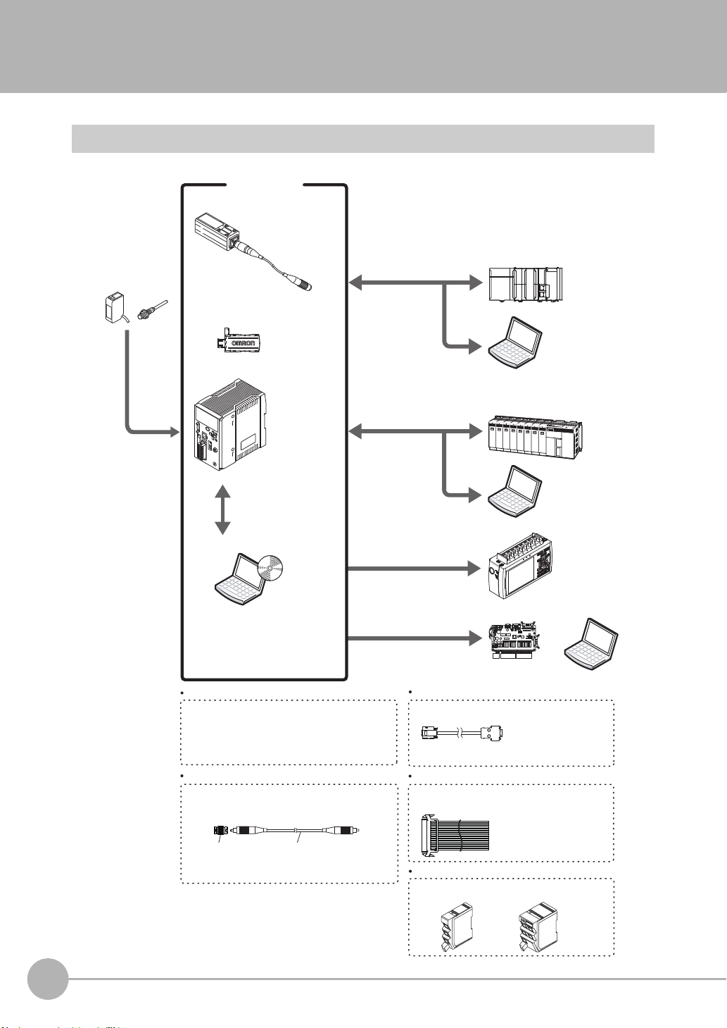
Photoelectr ic and
adjacent sensors
ZW series
Basic configuration
RS-232C cable
(note2)
PLC
(Note1) Ethernet cable (sold separately)
For PLC/programmable terminal: Z W-XPT 2
For personal computer: ZW-XRS2
Sensor head
Detects a target to
measure.
Sensor Controller
PC
PLC
PC
Data loggers, etc.
PC
High-speed
input board
(Note2) RS-232C cable (optional)
Depending o n connecting devices, exclusive cables
may be supplied.
Extension fiber cable (optional)
A exclusive extension fiber cable is available to
place the Sensor Head and Sensor Controller far apart
than the normal distance to each other.
Use the exclusive pro duct for correct measurements.
Connecting adapter
(included with the fiber
cable for extension)
ZW-XFC
Ethernet (note1) (note4)
(Note3) Parallel cable (optional)
A parallel cable for 52-pole extension connector
(ZW-XCP 2) with 2 m cable is available.
Sysmac Studio
Measurement
Sensor Edition
(Exc
lusive personal
computer software)
ZW-S07
ZW-S20
ZW-S30
ZW-S40
ZW-SR07
ZW-SR20
ZW-SR40
ZW-C10T/C10AT
ZW-C15T/C15AT
Ethernet (note1)
Sysmac-ME2@@L
Calibration ROM
(included with sensor head)
Associated with
the sensor on a
one-to-one basis
Performs
measurements
and outputs the
result.
Personal
computer
Allows making advanced settings and
checking up measured values easily using
exclusive personal computer soft ware.
It is also possible to use SmartMonitorZW
instead of Sysmac Studio.
Accessory for the Sensor Controller
ZW- C10AT/ C15 AT.
Measurement data can be easily loaded
into a PLC or personal computer through
Ethernet c onnec tions.
The Sensor Controller can be remotely controlled
from a persona l computer; inc luding switching
between or changing setting data and enteri ng
measuring triggers.
(Communication with multiple devices
simultaneously cannot be achieved via Ethernet.)
Various Controller operations,
including, taking measured values
and judgment results, switching
between or changing setting data
or entering measuring triggers, are
available.
Displaying analog signals in
waveform from measured values
or judgment results in color is
available.
Analog output
Outputt
ing me
asured values
or judgment results at a high
speed in parallel is available.
Parallel output (note3 )
The system receives
trigger signals to
control measuring
timings.
Prepare commercially available Ethernet cable
satisfyin g the following requirements:
- Category 5e or m ore, 30 m or less
- RJ45 connector (8-pin modular jack)
- For direct connection : Select cross cable.
-
For connection through an industrial switching hub (note 4 ):
Select straight cable.
Extension fiber cable
ZW-XF_ _ R
(2 m/ 5 m/10 m/ 20 m/ 30 m)
(Note 4) Indu strial network hub (sold separately)
Use the recommended products below:
W4S1-0_ (Omron)
3-port type
5-port type
2-1 System Configuration
System Configuration
20
System Configuration
ZW User's Manual

Connection Compatibility
Connected to
ZW-C1@T
Ethernet
(no-protocol)
Ethernet
(programmable noprotocol)
Other connection
Ethernet
(no-protocol)
--- Compatible Compatible
Compatible --- Compatible
RS-232C
(no-protocol)
I/O Cable
Important
Can be connected simultaneously via Ethernet with PC tools (Sysmac Studio, SmartMonitorZW) and another device
(PLC etc). Can be connected simultaneously via Ethernet with PC tools (Sysmac Studio, SmartMonitorZW) and
another device (PLC etc). The port number for the PC tool is fixed to 9600. When connecting different devices, set the
port number to other than 9600 (default value is 9601).
Product Model Application
ZW ZW-C1@T This Displacement Sensor performs measurements.
PC Tool Sysmac Studio
General-purpose Ethernet
cable
Special I/O Cable For connecting to a PLC
Industrial Ethernet Switching
Hub
Measurement Sensor
Edition
• SYSMAC-ME2@@L
(1 or 3 licences)
--- Prepare commercially available Ethernet cable
or programmable terminal
•ZW-XPT2
For connecting to a PC
•ZW-XRS2
• W4S1-03B
(3 ports type)
• W4S1-05B
• W4S1-05C
(5 ports type)
This is the setup application. It is part of the Sysmac Studio Package and it
runs on Windows.
This license provides the functions that are required to set up ZW Vision Sensors from the Sysmac Studio. This model number is for the license only. You
must also purchase the DVD for the Sysmac Studio Standard Edition
Ver.1.05 or higher.
satisfying the following requirements:
• Category 5e or more, 30 m or less
• RJ45 connector (8-pin modular jack)
• For direct connection: Select cross cable.
• For connection through an industrial switching hub: Select straight cable.
Connect the sensor with a PLC, programmable terminal, or personal
computer etc..
Used to connect multiple sensors or PLCs using Ethernet.
2
Installation and Connections
ZW User's Manual
System Configuration
21
2-2 Part Names and Functions
1
1
5
4
5
4
2
2
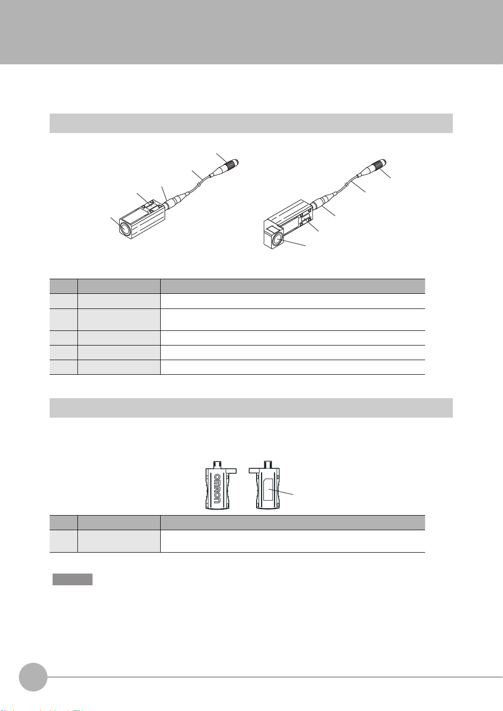
Straight type Right angle type
3
3
1
The following describes the names and functions of parts of the Sensor Head, Calibration ROM and Sensor
Controller.
Sensor Head
No. Names Functions
1 Projector/receiver Projects and receives light.
2 Serial number. Serial number.
3 Fiber interface Interfaces the Sensor Head and optical fiber (unremovable).
4 Fiber Cable Sends or receives light signals to/from the Sensor Controller.
5 Fiber Connector Couples the Sensor Controller and fiber cable.
Only a calibration ROM with the same serial number is available.
Calibration ROM
This ROM is associated with the sensor on a one-to-one basis, and operates connected to the Sensor
Controller.
No. Names Functions
1 Serial number Serial number.
Important
Use with the Calibration ROM always connected. If the Calibration ROM is not connected, an error is displayed.
22
Part Names and Functions
Only a Sensor Head with the same serial number is available.
ZW User's Manual
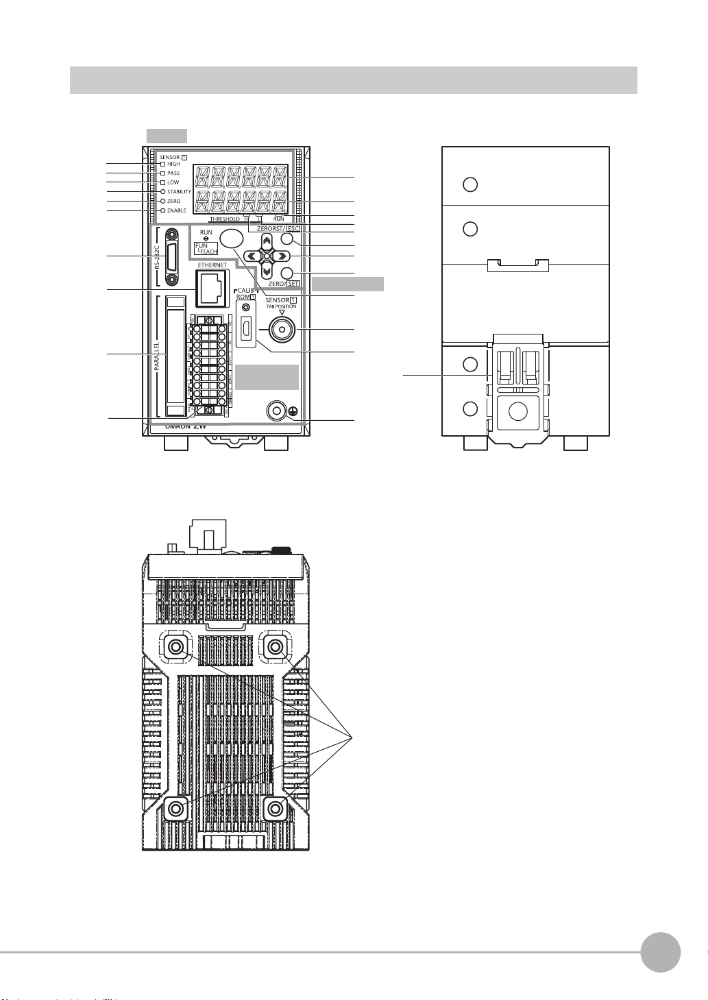
Sensor Controller
1
2
3
4
5
6
9
10
11
13
15
17
20
16
12
14
18
21
22
23
8
7
<Front view>
<Rear view>
19
<Bottom view>
24
Display
Control panel
Connectors/
terminals
2
Installation and Connections
ZW User's Manual
Part Names and Functions
23
Front view
● Display
No. Names (light color) Functions
1 HIGH indicator (orange) The HIGH indicator is lit while judgment is resulted in HIGH (HIGH threshold value <
2 PASS indicator (green) The PASS indicator is lit while judgment is resulted in PASS (LOW threshold value
3 LOW indicator (orange) The LOW indicator is lit while judgment is resulted in LOW (measured value < LOW
4 STABILITY indicator (green) The STABILITY indicator is lit while a measured value is within the measuring range.
5 ZERO indicator (green) The Zero Reset indicator is lit while the zero reset function is enabled.
6 ENABLE indicator (green) The ENABLE indicator lights when the Sensor is ready for measurement. It goes off when
7 Main display (red) The main display shows measured values and/or function names.
8 Sub-display (green) The sub-display shows additional information for measured values or setting values for
9 RUN indicator (green) The RUN indicator is lit in the RUN mode, and goes out in the FUN mode.
10 THRESHOLD-L indicator
(orange)
11 THRESHOLD-H indicator
(orange)
measured value).
measured value HIGH threshold value).
threshold value).
It goes out if a measured value is out of the measuring range.
measurement is not possible (e.g. when the received light amount is excessive or
insufficient, when the measuring range is exceeded, when the calibration ROM is not
connected, or when measurement is not being performed in FUN mode).
functions.
The LOW threshold value indicator is lit when the Sub-display indicates a LOW threshold
value.
The HIGH threshold value indicator is lit when the Sub-display indicates a HIGH threshold
value.
● Control panel
No. Names Functions
12 ZERORST/ESC key These keys function differently depending on operation modes.
13 (LEFT) key
(RIGHT) key
(UP) key
(DOWN) key
14 ZERO/SET key
15 Mode switching key
9-2 Functions of Operating Keys p.220
24
Part Names and Functions
ZW User's Manual

● Connectors/terminals
No. Names Functions
16 RS-232C connector Connect the RS-232C cable when you are connecting the system with a PLC or personal
17 Ethernet connector This connector is used to connect with a personal computer through Ethernet.
18 52-pole expansion connector The 52-pole expansion connector is used to utilize extended functions, such as binary I/
19 20-pole terminal block The 20-pole terminal block connects the Sensor Controller DC24 V power supply and
20 Fiber connector The fiber connector connects the fiber cable.
21 ROM connector The ROM connector connects the calibration ROM.
22 Frame ground terminal This is the connector for frame ground. It connects grounding wire.
computer through RS-232C.
For the RS-232C cable, please use the following exclusive products:
If you use a cable not included in the exclusive products, a false operation or breakdown
may result.
• For connecting to a PLC or programmable terminal: ZW-XPT2
• For connecting to a PC: ZW-XRS2
Prepare commercially available Ethernet cable satisfying the following requirements:
• Category 5e or more, 30 m or less
• RJ45 connector (8-pin modular jack)
• For one-to-one connection: Select cross cable.
• For connection through an industrial switching hub: Select straight cable.
(Recommended hub: W4S1-0@ (Omron))
Os, including output for measured value, GATE signal or binary output task number outputs, or binary output object task selection input signals; or bank I/O, including bank number output or bank select input .
A parallel cable for 52-pole extension connector (ZW-XCP2) with 2 m cable is available.
basic I/Os, including output for analog voltage, analog current, judgment, ALARM, BUSY
or ENABLE, or input for ZERO, RESET, TIMING or LED-OFF. The length of Cables
should be less than 30 m.
2
Installation and Connections
Rear view
No. Names Functions
23 DIN track attachment hook Used when fixing the Sensor Controller on DIN track.
Bottom view
No. Names Functions
24 Installation hole Used when fixing the Sensor Controller with screws.
ZW User's Manual
Part Names and Functions
25
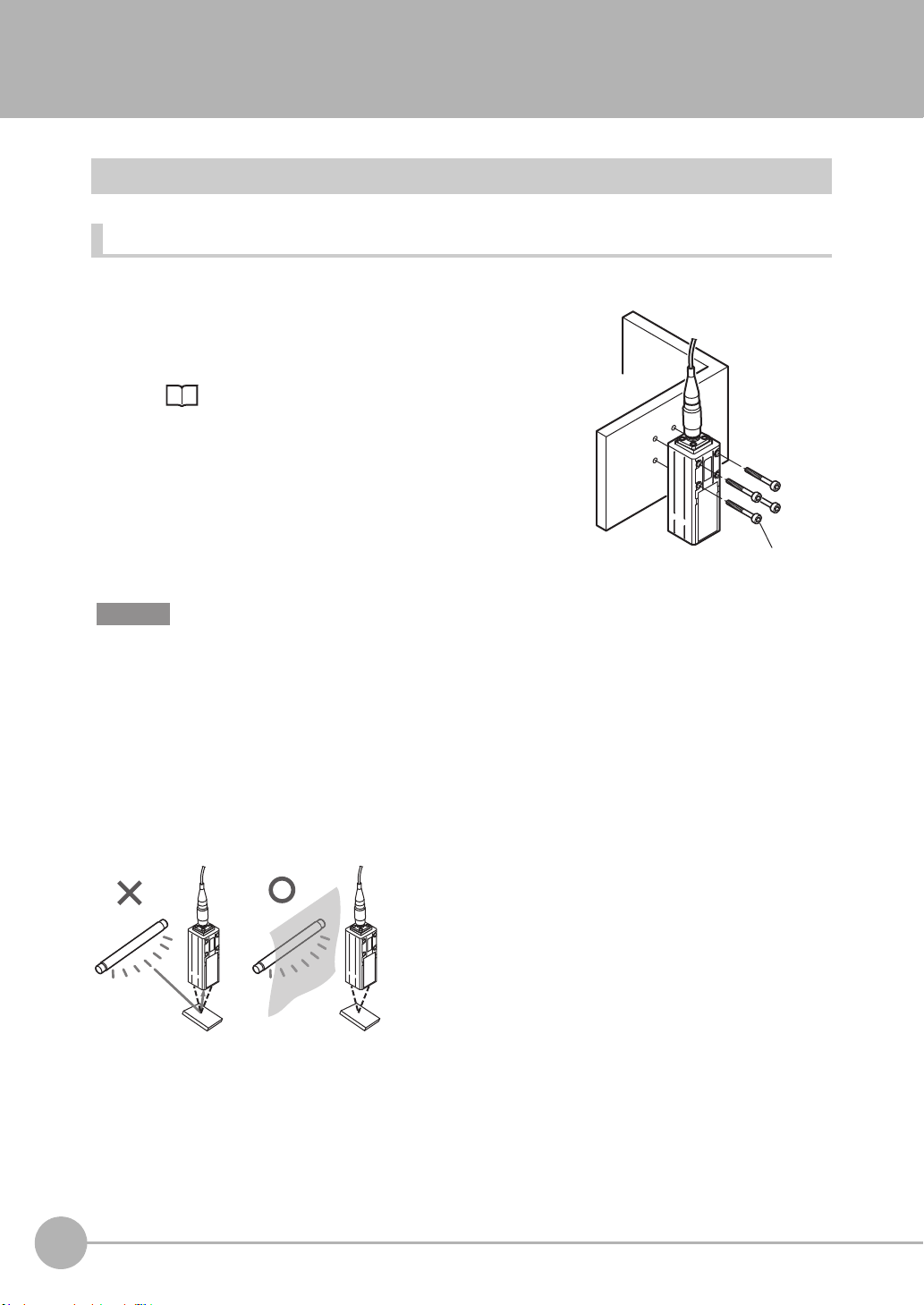
2-3 Installation
M3 screw×4
Installation of Sensor Head
Installation procedure
1 Place the Sensor Head with an appropriate distance from
the target to measure, fixing it by tightening four M3 screw
inserted into their respective installation holes.
Tightening torque: 0.54 N • m
10-1 Specifications and External Dimensions p.282
Important
• For the location screw holes, see the external dimensions.
• When measuring on a high-reflectivity object, such as a mirror or wafer, false measured values beyond the
measuring range may be outputted. When an object with diffuse reflection is used, we recommend installing and
adjusting while watching the position of the spot.
Basic precautions for installation
Do not install the Sensor Head in a place where strong light hits the laser emitter/receiver section of the Sensor
Head. Also, if an object has a shiny surface, the light from the lighting will be reflected and a malfunction may
occur. In such a case, prevent reflection by, for example, covering the light to stop reflection.
26
Installation
ZW User's Manual
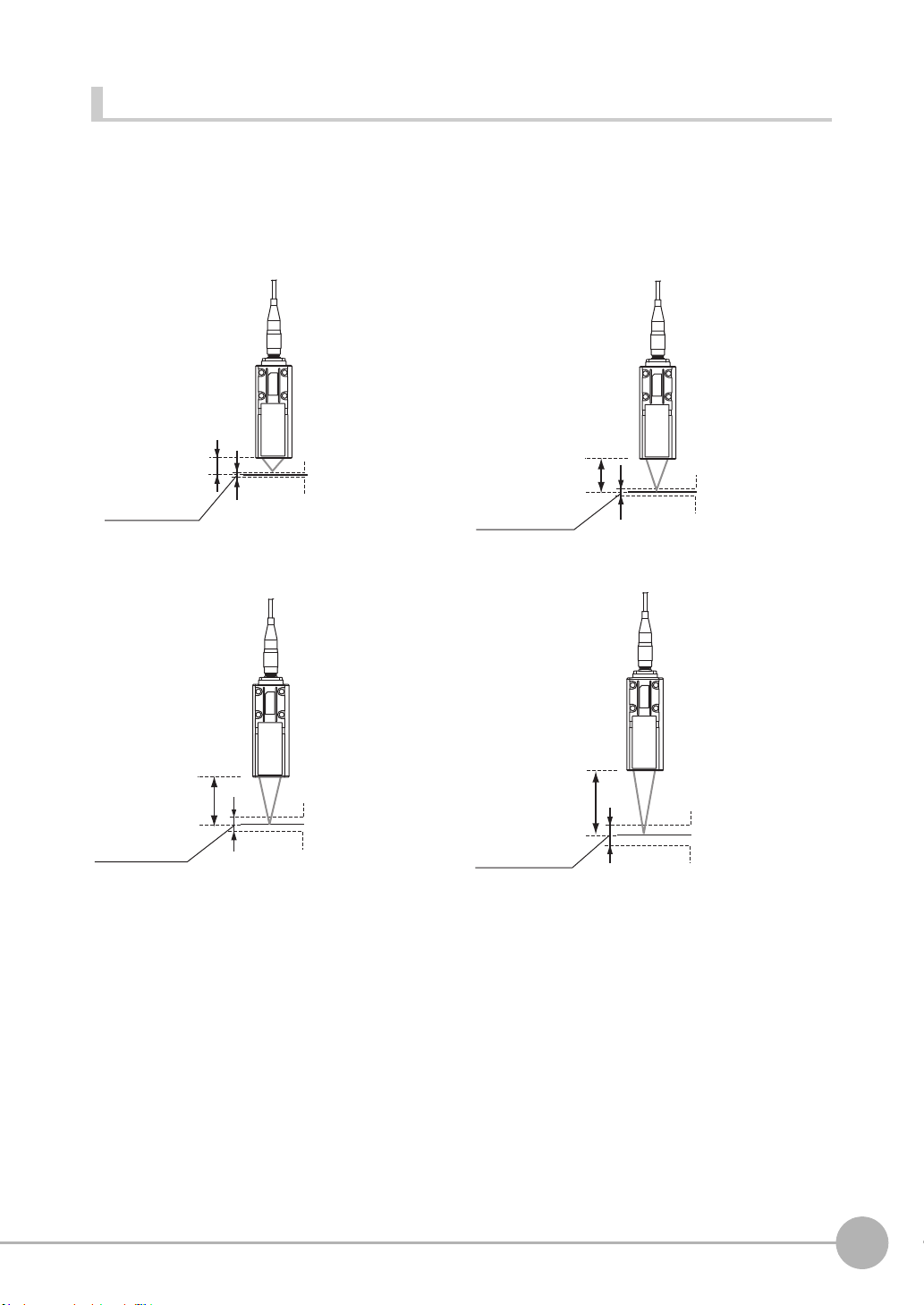
Measuring range
Measurement center
distance: 20 mm
Measurement center
distance: 7 mm
NEAR side: +1 mm
Measuring
center: 0 mm
FAR side: -1 mmMeasuring range
Measurement center
distance: 30 mm
NEAR side: +3 mm
Measuring
center: 0 mm
Measuring
center: 0 mm
FAR side: -3 mm
Measuring range
Measuring range
ZW-S20
ZW-S30
ZW-S40
Measurement center
distance: 40 mm
NEAR side: +6 mm
Measuring
center: 0 mm
FAR side: -6 mm
Measuring range
NEAR side: +0.3 mm
FAR side: -0.3 mm
ZW-S07
With the ZW series, the measurement center distance is expressed as 0 with the NEAR side as + and the FAR
side as -.
Straight type
2
Installation and Connections
ZW User's Manual
Installation
27
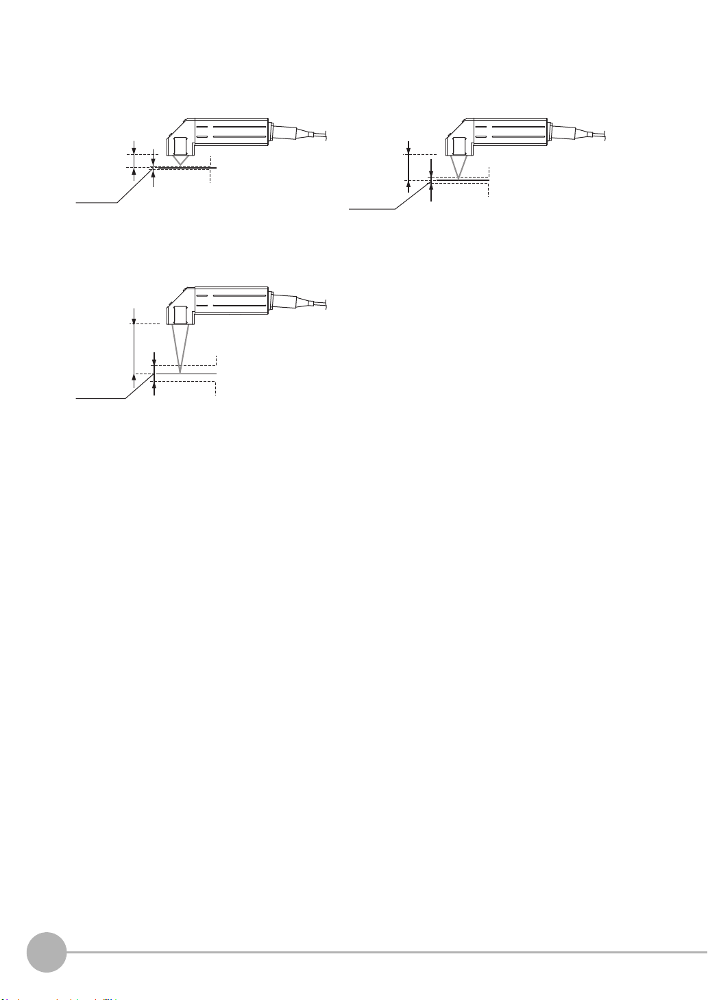
Right angle type
Measurement center
distance: 7 mm
Measurement center
distance: 20 mm
Measuring
center: 0 mm
Measuring
center: 0 mm
Measuring
range
Measuring
range
Measuring
range
NEAR side: +0.3 mm
FAR side: -0.3 mm
ZW-SR07 ZW-SR20
NEAR side: +1 mm
FAR side: -1 mm
ZW-SR40
Measurement center
distance: 40 mm
NEAR side: +6 mm
Measuring
center: 0 mm
FAR side: -6 mm
28
Installation
ZW User's Manual
 Loading...