

Page 1

Displacement Sensor
ZW-8000/7000/5000 series
Confocal Fiber Type
Displacement Sensor
User’s Manual for Communications Settings
ZW-8000@
ZW-7000@
ZW-5000@
Z363-E1-06
Page 2

Introduction
Thank you for purchasing the ZW-8000/7000/5000 Series.
This manual provides information regarding functions, performance and operating methods that
are required for using the ZW-8000/7000/5000 Series.
When using the ZW-8000/7000/5000 Series, be sure to observe the following:
• The ZW-8000/7000/5000 Series must be operated by personnel knowledgeable in electrical engineering.
• To ensure correct use, please read this manual thoroughly to deepen your understanding of the
product.
• Please keep this manual in a safe place so that it can be referred to whenever necessary.
Page 3

Terms and Conditions Agreement
(Please Read)
User’s Manual for
Communications
Settings
Overview of Communication Specifications
Parallel I/O Connection
EtherCAT Connection
EtherNet/IP Connection
No-protocol Connection
Sensor Controller Operations
1
2
3
4
5
6
Confocal Fiber Type
Disp
laceme
ZW-8000/7000/5000 Series
nt Sensor
Troubleshooting
Appendices
7
8
Page 4

Terms and Conditions Agreement
Read and understand this Manual
Please read and understand this catalog before purchasing the products. Please consult your OMRO N
representative if you have any questions or comments.
Warranties
• Exclusive Warranty
Omron’s e xc lus ive warranty is that the Products will be free from defects in materials and workmanship for a
period of twelve months from the date of sale by Omron (or such other period expressed in writing by
Omron). Omron disclaims all other warranties, express or implied.
• Limitations
OMRON MAKES NO WARRANTY OR REPRESENTATION, EXPRESS OR IMPLIED, ABOUT NONINFRINGEMENT, MERCHANTABILITY OR FITNESS FOR A PARTICULAR PURPOSE OF THE
PRODUCTS. BUYER ACKNOWLEDGES THAT IT ALONE HAS DETERMINED THAT THE PRODUCTS
WILL SUITABLY MEET THE REQUIREMENTS OF THEIR INTENDED USE.
Omron further disclaims all warranties and responsibility of any type for claims or expenses based on
i
nfringeme
obligation hereunder shall be, at Omro n’s election, to (i) replace (in the form originally shipped with Buyer
responsible for labor charges for removal or replacement thereof) the
non-complying Product, (ii) repair the non-complying Prod
to the purchase price of the non-comply ing Product; pro vid ed that in no event shall Omron be responsib le for
warranty, repair , indemnity or any other claims or expenses regarding the Products unless Omron’s analysis
confirms that the Products were properly handled, stored, installed and maintained and not subject to
contamination, abuse, mis use or inappropriate modification. Return of any Products by Buyer must be
approved in writing by Omron before shipment. Omron Companies shall not be liable for the suitability or
unsuitability or the results from the use of Products in combination with any electrical or electronic
components, circuits, syst em assemb li es or an y othe r materials or substa nces or en vironme nts . An y advice,
recommendations or information given orally or in writing, are not to be construed as an amendment or
addition to the above warranty.
See http://www.omron.com/global/ or contact your Omron representative for published information.
nt by the Products or otherwise of any intell ectual property right. (c) Buyer Remedy. Omron’s sole
uct, or (iii
) repay or credit Buyer an amount equal
Limitation on Liability; Etc.
OMRON COMPANIES SHALL NOT BE LIABLE FOR SPECIAL, INDIRECT, INCIDENTAL, OR
CONSEQUENTIAL DAMAGES, LOSS OF PROFITS OR PRODUCTION OR COMMERCIAL LOSS IN ANY
WAY CONNECTED WITH THE PRODUCTS, WHETHER SUCH CLAIM IS BASED IN CONTRACT,
WARRANTY, NEGLIGENCE OR STRICT LIABILITY.
Further, in no event shall liability of Omron Companies exceed the individual price of the Product on which
l
is asserted.
iability
Suitability of Use
Omron Companies shall not be responsible f or conf ormity with any standards , codes or regulations which apply
to the combination of the Product in the Buyer’s application or use of the Product. At Buyer’s request, Omron
will provide applicable third party certification documents identifying ratings and limitations of use which apply
to the Product. This information by itself is not sufficient for a complete determination of the suitability of the
Product in combination with the end product, machine, system, or other application or use. Buyer shall be
solely responsible f or determining appropriateness of the particular Product with respect t o Buyer’s application,
product or system. Buyer shall take application responsibility in all cases.
NEVER USE THE PRODUCT FOR AN APPLICATION INVOLVING SERIOUS RISK TO LIFE OR PROPERTY
2
User’s Manual for Communications Settings
ZW-8000/7000/5000
Page 5

OR IN LARGE QUANT ITIES WITHOUT ENSURING THAT THE SYSTEM AS A WHOLE HAS BEEN
DESIGNED TO ADDRESS THE RISKS, AND THAT THE OMRON PRODUCT(S) IS PROPERLY RATED AND
INSTALLED FOR THE INTENDED USE WITHIN THE OVERALL EQUIPMENT OR SYSTEM.
Programmable Products
Omron Companies shall not be responsible for the user’s programming of a programmable Product, or any
consequence thereof.
Performance Data
Data presented in Omron Company websites, catalogs and other materials is provided as a guide for the user
in determining suitability and does not constitute a warranty. It may represent the result of Omron’s test
conditions, and the user must correlate it to actual application requirements. Actual performance is subject to
the Omron’s Warranty and Limitations of Liability.
Change in Specifications
Product specifications and accessories may be changed at any time based on improvements and other
reasons. It is our practice to change part numbers when published ratings or features are changed, or when
significant construction changes are made. Ho wever, some specifications of the Product may be changed
without any notice. When i n doubt, special part numbers may be assigned to fix or establish key specifications
for your application. Please consult with your Omron’s representative at any time to confirm actual
specifications of purchased Product.
Errors and Omissions
Information presented by Omron Companies has been checked and is believed to be accurate; however, no
responsibility is assumed for clerical, typog raphical or proofreading errors or omissions.
ZW-8000/7000/5000
User’s Manual for Communications Settings
3
Page 6

Precautions on Safety
For details on the precautions on safety, refer to the following manual:
"Precautions on Safety" described in Displac ement Se nsor ZW-8000/7000/5000 series Confocal Fiber
Type Displacement Sensor User's Manual (Z362)
Precautions for Safe Use
For details on the precautions for safe use, refer to the following manual:
"Precautions for Safe Use" described in Displacement Sensor ZW-8000/7000/5000 series Confocal
Fiber Type Displacement Sensor User's Manual (Z362)
Precautions for Correct Use
For details on the precautions for correct use, refer to the following manual:
"Precautions for Correct Use" described in Displacemen t Sensor ZW-8000/7000/5000 series Confocal
Fiber Type Displacement Sensor User's Manual (Z362)
Editor's Note
● Meaning of Symbols
Menu items that are displa yed on the main or sub-display, and windows, dialog boxes and other GUI elements
displayed on the personal computer are indicated enclosed by brackets [ ].
●
Visual Aids
Important
Note
Optional
Indicates points that are important to achie ve the full product performance, such as oper a tiona l
precautions.
Indicates application procedures.
Indicates pages where related information can be found.
Indicates that the setting is optional in a configuration procedure.
Copyrights and Trademarks
• Sysmac is a trademark or registered trademark of OMRON corporation in Japan and other countries for our FA
equipment products.
• Windows, Windows XP, Windows Vista, Windows 7, and Windows 8 are registered tr
Corporation in the USA and other countries.
• EtherCAT
Germany.
• ODVA, CIP, CompoNet, DeviceNet, and EtherNet/IP are trademarks of ODVA.
• Microsoft product screen shots reprinted with p
• Other system names and product names that appear in this manual are the trademarks or
the respective companies.
®
is registered trademark and patented technology that is licensed by Beckhoff Automation GmbH,
ermission from
Microsoft Corporation.
ademarks of Microsoft
registered trademarks of
4
User’s Manual for Communications Settings
ZW-8000/7000/5000
Page 7

Notice
• Photocopying, duplication, or copying of all or part of this manual without permission is prohibited.
• Please understand that the specifications and other contents of this manual are subject to change f
without notice.
• Every effort has been made to ensure the accuracy of the contents of this manual, but if you should notice an
mistake, questionable section, or the like in this manual, please contact an OMRON branch or sales office.
If you do so, please also tell us the manual number, which is found at the end of the manual.
or improvement
y
ZW-8000/7000/5000
User’s Manual for Communications Settings
5
Page 8

Relevant Manuals
The following table provides the relevant manuals for the ZW-8000/7000/5000 series Conf ocal Fiber Type
Displacement Sensor.
Read all of the manuals that are relevant to your system configuration and application before you use the ZW8000/7000/5000 series Confocal Fiber T ype Displacement Sensor.
Most operations are performed from the Sysmac Studio Automation Software. Refer to the “Sysmac Studio
V ersion 1 Operation Manual (Cat. No. W504)” for information on the Sysmac Studio.
Purpose of use Manual
Overview of ZW-8000/7000/5000
series
Setup and Wiring
Basic Operation
Function Setting
Offline Setting
Confirm the Menu List
Connecting to the Sensor Controller
Connecting to the Sensor Controller for
Communication Settings
Overview of Communication Specifica-
tions
Parallel I/O
EtherCAT
EtherNet/IP
No-protocol
Specifications and External Dimen-
sions
Processing Item List
System Data List
Object Dictionary
Update the Firmware
Troubleshooting
Error Messages
ZW-8000/7000/5000 series Confocal Fiber
Type Displacement Sensor User's Manual
●
●
●
●
●
●
●
●
●
●
ZW-8000/7000/5000 series Conf o cal Fiber
Type Displacement Sensor User's Manual
for Communications Settings
●
●
●
●
●
●
●
●
●
●
6
User’s Manual for Communications Settings
ZW-8000/7000/5000
Page 9

Related Manuals
The related manuals are described the below tables. Please check the manuals.
Manual name Cat. No. Model numbers Application Description
Sysmac Studio Version 1
Operation Manual
Confocal Fiber Type
Displacement Sensor
ZW-8000/7000/5000
series User's Manual
Confocal Fiber Type
Displacement Sensor
ZW-8000/7000/5000
series User's Manual for
Communication Settings
(This manual)
W504 SYSMAC-SE2@@@ Learning about the operating
Z362 ZW-8000@
Z363 ZW-8000@
ZW-7000@
ZW-5000@
ZW-7000@
ZW-5000@
procedures and functions of
the Sysmac Studio.
To learn how to set-up of Confocal Fiber Type Displacement
Sensor of ZW-8000/7000/5000
series.
To learn how to use communication settings of Confocal
Fiber Type
Displacement Sensor of ZW8000/7000/5000 series.
Describes the operating procedures of the Sysmac Studio.
Describes how to set-up of
Confocal Fiber Type
Displacement Sensor of ZW8000/7000/5000 series.
Describes how to use communication settings of Confocal
Fiber Type
Displacement Sensor of ZW8000/7000/5000 series.
ZW-8000/7000/5000
User’s Manual for Communications Settings
7
Page 10

8
User’s Manual for Communications Settings
ZW-8000/7000/5000
Page 11

Table of Contents
Editor's Note . . . . . . . . . . . . . . . . . . . . . . . . . . . . . . . . . . . . . . . . . . . . . . . . . . . .4
Copyrights and Trademarks . . . . . . . . . . . . . . . . . . . . . . . . . . . . . . . . . . . . . . . .4
Notice . . . . . . . . . . . . . . . . . . . . . . . . . . . . . . . . . . . . . . . . . . . . . . . . . . . . . . . . . 5
Relevant Manuals . . . . . . . . . . . . . . . . . . . . . . . . . . . . . . . . . . . . . . . . . . . . . . . .6
Related Manuals . . . . . . . . . . . . . . . . . . . . . . . . . . . . . . . . . . . . . . . . . . . . . . . . .7
1.Overview of Communication Specifications
1-1 Overview of Communication Specifications . . . . . . . . . . . . . . . . . . . 14
Overview of Communication Specifications . . . . . . . . . . . . . . . . . . . . . . . . . . .14
1-2 Checking the System Configuration . . . . . . . . . . . . . . . . . . . . . . . . . . 15
System Configuration . . . . . . . . . . . . . . . . . . . . . . . . . . . . . . . . . . . . . . . . . . . .16
Connection Compatibility . . . . . . . . . . . . . . . . . . . . . . . . . . . . . . . . . . . . . . . . . .17
2.Parallel I/O Connection
2-1 Parallel I/O Connection. . . . . . . . . . . . . . . . . . . . . . . . . . . . . . . . . . . . . 20
I/O Signal Functions . . . . . . . . . . . . . . . . . . . . . . . . . . . . . . . . . . . . . . . . . . . . .20
Settings for Parallel Input . . . . . . . . . . . . . . . . . . . . . . . . . . . . . . . . . . . . . . . . .22
Settings for Analog Output . . . . . . . . . . . . . . . . . . . . . . . . . . . . . . . . . . . . . . . .23
Settings for Judgment Output . . . . . . . . . . . . . . . . . . . . . . . . . . . . . . . . . . . . . .29
Settings for Bank Control . . . . . . . . . . . . . . . . . . . . . . . . . . . . . . . . . . . . . . . . .32
Timing Chart . . . . . . . . . . . . . . . . . . . . . . . . . . . . . . . . . . . . . . . . . . . . . . . . . . .33
Table of Contents
3.EtherCAT Connection
3-1 EtherCAT Connection. . . . . . . . . . . . . . . . . . . . . . . . . . . . . . . . . . . . . . 44
Overview of EtherCAT Networks . . . . . . . . . . . . . . . . . . . . . . . . . . . . . . . . . . . .44
Communication Methods for Measurement Sensor when Connect ed via EtherCAT
48
Setting Communications Specifications (EtherCAT Communications) . . . . . . .51
List of I/O Ports for Each Area (PDO Mapping) and Memory Assignments . . . 52
Timing Chart (EtherCAT) . . . . . . . . . . . . . . . . . . . . . . . . . . . . . . . . . . . . . . . . . .75
Sample Ladder Program (EtherCAT) . . . . . . . . . . . . . . . . . . . . . . . . . . . . . . . .85
Sysmac Device Features (EtherCAT) . . . . . . . . . . . . . . . . . . . . . . . . . . . . . . . .86
4.EtherNet/IP Connection
4-1 EtherNet/IP Connection . . . . . . . . . . . . . . . . . . . . . . . . . . . . . . . . . . . . 90
ZW-8000/7000/5000
User’s Manual for Communications Settings
9
Page 12

Introduction to EtherNet/IP . . . . . . . . . . . . . . . . . . . . . . . . . . . . . . . . . . . . . . . .90
Communication Methods for Measurement Sensor when Connect ed vi a EtherNe t/
IP . . . . . . . . . . . . . . . . . . . . . . . . . . . . . . . . . . . . . . . . . . . . . . . . . . . . . . . . . . . .92
Setting Communications Specifications (EtherNet/IP) . . . . . . . . . . . . . . . . . . .95
Tag Data Link Setting Methods . . . . . . . . . . . . . . . . . . . . . . . . . . . . . . . . . . . . .97
Memory Assignments and Commands . . . . . . . . . . . . . . . . . . . . . . . . . . . . . .100
Timing Chart (EtherNet/IP) . . . . . . . . . . . . . . . . . . . . . . . . . . . . . . . . . . . . . . . 112
Sample Ladder Program (EtherNet/IP) . . . . . . . . . . . . . . . . . . . . . . . . . . . . . .117
5.No-protocol Connection
5-1 No-protocol Connection. . . . . . . . . . . . . . . . . . . . . . . . . . . . . . . . . . . 120
Outline of No-protocol Communications . . . . . . . . . . . . . . . . . . . . . . . . . . . . .120
Setting Communications Specifications (Ethernet Co mmunications) . . . . . . .121
Setting Communications Specifications (RS-232C Communications) . . . . . .123
Setting for serial data output after application of measured valu e . . . . . . . . .124
Command List . . . . . . . . . . . . . . . . . . . . . . . . . . . . . . . . . . . . . . . . . . . . . . . . .128
Command Format . . . . . . . . . . . . . . . . . . . . . . . . . . . . . . . . . . . . . . . . . . . . . .130
6.Sensor Controller Operations
6-1 Connecting Parallel I/O. . . . . . . . . . . . . . . . . . . . . . . . . . . . . . . . . . . . 160
Settings for Analog Output . . . . . . . . . . . . . . . . . . . . . . . . . . . . . . . . . . . . . . .160
Settings for Judgment Output . . . . . . . . . . . . . . . . . . . . . . . . . . . . . . . . . . . . .164
Settings for Processing When Measurem e nt Is No t Po ssi b le . . . . . . . . . . . . .166
Settings for Digital Output . . . . . . . . . . . . . . . . . . . . . . . . . . . . . . . . . . . . . . . .169
Settings for Parallel Input . . . . . . . . . . . . . . . . . . . . . . . . . . . . . . . . . . . . . . . .171
Settings for TIMING Input Mode . . . . . . . . . . . . . . . . . . . . . . . . . . . . . . . . . . .172
Setting for Internal Logging . . . . . . . . . . . . . . . . . . . . . . . . . . . . . . . . . . . . . . .173
6-2 Connecting with EtherCAT. . . . . . . . . . . . . . . . . . . . . . . . . . . . . . . . . 175
Setting Fieldbus . . . . . . . . . . . . . . . . . . . . . . . . . . . . . . . . . . . . . . . . . . . . . . . .175
Setting GATE Signal ON Time . . . . . . . . . . . . . . . . . . . . . . . . . . . . . . . . . . . .176
6-3 Connecting with EtherNet/IP . . . . . . . . . . . . . . . . . . . . . . . . . . . . . . . 177
Network Settings of the Sensor . . . . . . . . . . . . . . . . . . . . . . . . . . . . . . . . . . . .177
Setting Fieldbus . . . . . . . . . . . . . . . . . . . . . . . . . . . . . . . . . . . . . . . . . . . . . . . .178
6-4 Connecting by No-protocol Communications . . . . . . . . . . . . . . . . . 179
Initial Settings for No-protocol Communications . . . . . . . . . . . . . . . . . . . . . . .179
Setting Communications Specifications (RS-232C Communications) . . . . . .180
Setting Serial Data Output . . . . . . . . . . . . . . . . . . . . . . . . . . . . . . . . . . . . . . . .181
Set the delimiter . . . . . . . . . . . . . . . . . . . . . . . . . . . . . . . . . . . . . . . . . . . . . . .182
7.Troubleshooting
7-1 Error Messages . . . . . . . . . . . . . . . . . . . . . . . . . . . . . . . . . . . . . . . . . . 184
10
Errors for EtherCAT Connection (Sysmac Error Status) . . . . . . . . . . . . . . . . .184
Errors for EtherCAT Connection (SDO) . . . . . . . . . . . . . . . . . . . . . . . . . . . . .196
User’s Manual for Communications Settings
ZW-8000/7000/5000
Page 13

Errors for Ethernet or EtherNet/IP Connection . . . . . . . . . . . . . . . . . . . . . . . .197
Errors Common to All Communication States . . . . . . . . . . . . . . . . . . . . . . . . .198
7-2 Troubleshooting . . . . . . . . . . . . . . . . . . . . . . . . . . . . . . . . . . . . . . . . . 199
8.Appendices
8-1 Processing Item Data List . . . . . . . . . . . . . . . . . . . . . . . . . . . . . . . . . 202
8-2 System data list. . . . . . . . . . . . . . . . . . . . . . . . . . . . . . . . . . . . . . . . . . 212
8-3 Object Dictionary . . . . . . . . . . . . . . . . . . . . . . . . . . . . . . . . . . . . . . . . 214
Object Dictionary Area . . . . . . . . . . . . . . . . . . . . . . . . . . . . . . . . . . . . . . . . . .214
Data type . . . . . . . . . . . . . . . . . . . . . . . . . . . . . . . . . . . . . . . . . . . . . . . . . . . . .214
Description Format of Objects . . . . . . . . . . . . . . . . . . . . . . . . . . . . . . . . . . . . .215
Communication Object . . . . . . . . . . . . . . . . . . . . . . . . . . . . . . . . . . . . . . . . . .216
PDO Mapping Object . . . . . . . . . . . . . . . . . . . . . . . . . . . . . . . . . . . . . . . . . . .219
Sync Manager Communication Object . . . . . . . . . . . . . . . . . . . . . . . . . . . . . .224
Manufacturer Unique Objects . . . . . . . . . . . . . . . . . . . . . . . . . . . . . . . . . . . . .227
Index . . . . . . . . . . . . . . . . . . . . . . . . . . . . . . . . . . . . . . . . . . . . . . . . . . . . . 277
Revision History. . . . . . . . . . . . . . . . . . . . . . . . . . . . . . . . . . . . . . . . . . . . 278
Table of Contents
ZW-8000/7000/5000
User’s Manual for Communications Settings
11
Page 14

12
User’s Manual for Communications Settings
ZW-8000/7000/5000
Page 15

1
Overview of Communication Specifications
Overview of Communication Specifications
1-1 Overview of Communication Specifications . . . . . . . . . . . . . . . . . . . .14
1-2 Checking the System Configuration. . . . . . . . . . . . . . . . . . . . . . . . . . .15
Page 16

1-1
Overview of Commu nication Specifications
Overview of Communication Specifications
This chapter provides a general description of the communication specifications and sensor control method,
which is necessary to know before setting up the communication between the ZW-8000/7000/5000 series and
an external device.
14
Overview of Communication Specifications
User’s Manual for Communications Settings
ZW-8000/7000/5000
Page 17

1-2 Checking the System Configuration
This product is a displacement sensor of the confocal fiber type.
The connection with an external de vice such as a PLC and a personal computer allows a measurement
command to be input and measurement results to be output from the external device.
1
Overview of Communication Specifications
ZW-8000/7000/5000
User’s Manual for Communications Settings
Checking the System Configuration
15
Page 18

System Configuration
Connecting with EtherCAT
(when the master is NX/NJ Series)
EtherCAT Master
Sysmac Studio
Standard Edition
I/O control PLC
Trigger input
sensor
24-V
power supply
Power Cable
Parallel Cable
Connecting with EtherCAT (when the
master is other than NX/NJ Series)
Sysmac Studio
Displacement Sendor
Edition
General-purpose
Ethernet Cable
I/O control PLC
Trigger input
sensor
24-V
power supply
Power
Cable
Parallel Cable
NX/NJ-series Machine
Automation Controller
Special EtherCAT
Cable (RJ45/RJ45)
Special EtherCAT Cable
(RJ45/RJ45)
EtherCAT Master
Programmable Controller
with CJ2 CPU Unit
Special EtherCAT
Cable (RJ45/RJ45)
Special EtherCAT Cable
(RJ45/RJ45)
General-purpose USB Cable
General-purpose Ethernet Cable
ZW-8000@/7000@/5000@
Special EtherCAT Cable
ZW-8000@/7000@/5000@
Special EtherCAT Cable
Other EtherCAT slaves
(RJ45/RJ45)
Other EtherCAT slaves
(RJ45/RJ45)
EtherNet/IP and No-protocol
Ethernet Connections
Sysmac Studio
Displacement Sendor
Edition
General-purpose
Ethernet Cable
Industrial
EtherNet/IP/
Ethernet
Switching Hub
24-V
power supply
16
Checking the System Configuration
Power Cable
Control signal
input sensor
General-purpose
Ethernet Cable
General-purpose
Ethernet Cable
I/O control PLC
Control PLC, RC, or MC
Programmable Controller
with CJ2 CPU Unit
General-purpose
Ethernet Cable
Parallel Cable
NX/NJ-series Machine
Automation Controller
ZW-8000@/7000@/5000@
User’s Manual for Communications Settings
ZW-8000/7000/5000
Page 19

Connection Compatibility
Connected to
ZW-8000@/7000@/
5000@
EtherCAT --- Not compatible Compatible Compatible Compatible
EtherNet/IP Not compatible --- Compatible Compatible Compatible
Ethernet
(no-protocol)
RS-232C
(no-protocol)
Other connection
EtherCAT EtherNet/IP Ethernet
Compatible Compatible --- Compatible Compatible
Compatible Compatible Compatible --- Compatible
(no-protocol)
RS-232C
(no-protocol)
Parallel I/O Cable
Important
• EtherCAT and EtherNet/IP connections cannot be used at the same time.
• Can be connected simultaneously via Ethernet with PC tools (Sysmac Studio, Sma
rtMonitorZW) and another
device (PLC etc). Can be connected simultaneously via Ethernet with PC tools (Sysmac Studio, SmartMonitorZW)
and another device (PLC etc). The port number for the PC tool is 9600 (fixed) and 9602 (fixed). When connecting
different devices, set the port number to other than 9600 and 9602 (default value is 9601).
• When the measurement cycle is 40µs or less and ETherCA
Product Model Application
ZW ZW-8000@/7000@/5000@ This Displacement Sensor performs measurements.
PC Tool Sysmac Studio Standard
Special EtherCAT Cable * The Special EtherCAT Cable connects the Sensor to another Sensor or to
General-purpose Ethernet
cable
Special RS-232C Cable For connecting to a PLC or
Industrial EtherNet/IP /
Ethernet Switching Hub
Edition
• SYSMAC-SE200D
(no licenses included
(media only))
• SYSMAC-SE201L
(1-license edition)
• SYSMAC-SE2@@L
(multilicense editions
(3, 10, 30, or 50
licenses))
Sysmac Studio
Measurement Sensor
Edition
• SYSMAC-ME00@L
(1 or 3 licences)
--- Prepare commercially available Eth ernet cable
programmable terminal
•ZW-XPT2
For connecting to a PC
•ZW-XRS2
• W4S1-03B
(3 ports type)
• W4S1-05B
• W4S1-05C
(5 ports type)
This is the setup application. It is part of the Sysmac Studio Package and it
runs on Windows.
The Sysmac Studio comes in two different editions .
• Sysmac Studio Standard Edition
• Sysmac Studio Measurement Sensor Edition
another EtherCAT device.
satisfying the following requirements:
• Category 5e or more, 30 m or less
• RJ45 connector (8-pin modular jack)
• For direct connection: Select cross cable.
• For connection through an industrial switching hub: Select straight cable.
Connect the sensor with a PLC, programmab le terminal, or personal
computer etc..
The Switching Hub connects multiple Sensors to one Touch Finder or one
computer running PC Tool.
T is connected, analog output is not e
The Sysmac Studio provides an integrated development environment for
the NX/NJ series Controllers and other Machine Automation Controllers
and EtherCAT Slaves. It supports setup, programming, debugging,
operation, and maintenance.
The Sysmac Studio Standard Edition DVD includes Support Software for
EtherNet/IP, DeviceNet, serial communications, and PT screen design
(CX-Designer). Refer to the Sysmac catalog (Cat. No. P072) for details.
This license provides the functions that are required to set up ZW-8000/
7000/5000 Series Vision Sensors from the Sysmac Studio. This model
number is for the license only. You must also purchase the DVD for the
Sysmac Studio Standard Edition Ver.1.22 or higher.
xecuted.
1
Overview of Communication Specifications
ZW-8000/7000/5000
User’s Manual for Communications Settings
Checking the System Configuration
17
Page 20

Product Model Application
EtherCAT Junction Slave • GX-JC03
(3 ports type)
•GX-JC06
(6 ports type)
Used to connect multiple sensors or PLCs using EtherCAT.
*: Refer to Displacement Sensor ZW-8000/7000/5000 series Confocal Fiber Type Displacement Sensor User's
Manual (Z362) "9-1 Specifications and External Dimensions".
18
Checking the System Configuration
User’s Manual for Communications Settings
ZW-8000/7000/5000
Page 21

Parallel I/O Connection
2-1 Parallel I/O Connection . . . . . . . . . . . . . . . . . . . . . . . . . . . . . . . . . . . . . 20
2
Parallel I/O Connection
Page 22

2-1 Parallel I/O Connection
I/O Signal Functions
The following describes the functions of I/O signals.
Analog Output Terminals
Analog output
Name Description
Analog voltage output This outputs the measured value from -10 V to +10 V as the voltage value.
Analog current output This outputs the measured value, from 20 mA to 4 mA as the current value.
32-pole expansion connector
Judgment output
Name Description
HIGH output Judgment result HIGH (HIGH threshold value < measured value) is output.
PASS Output Judgment result PASS (LOW threshold v alue ≤ measured value ≤ HIGH threshold value) is
LOW output Judgment result LOW (LOW threshold value > measured value) is output.
When measurement not possible: Approx. 10.8V (default value, can be selected by user)
At alarm: Approx. 10.8V
When measurement not possible: Approx. 21 mA (default value, can be selected by user)
At alarm: Approx. 21 mA
output.
ALARM output
Name Description
ALARM output This turns ON when there is a system error.
BUSY output
Name Description
BUSY output This turns ON during sampling with the hold function enabled.
It allows you to check whether or not the self-tr
It also turns ON during bank switching.
This signal is turned ON in FUNC mode.
ENABLE output
Name Description
ENABLE output This turns ON when the sensor is ready for measurement.
20
Parallel I/O Connection
This output is interlocked with the ENABLE indicator.
igger is functioning correctly.
User’s Manual for Communications Settings
ZW-8000/7000/5000
Page 23

SYNCFLG/TRIGBUSY output
Name Description
SYNCFLG/TRIGBUSY output In the internal/PDO synchronized mode , this output sig nal operates a s SYNCFLG. This turns ON
when measurement synchronization processing is execut ed by SYNC input and the state
changes to one where normal measurement values can be output.
In the external synchronous measurement mode, t
turns ON while a measurement by TRIG input is being performed. The next TRIG input cannot
be turned ON until this turns OFF.
his output signal
operates as TRIGBUSY. This
STABILITY output
Name Description
STABILITY output Turns ON when the 1 surface is in the measuring range.
LOGSTAT output
Name Description
LOGSTAT output This turns ON while internal logging is in execution.
LOGERR output
Name Description
LOGERR output Turns ON when memory for Internal logging is full and the executes Internal logging.
2
Parallel I/O Connection
TASKSTAT output
Name Description
TASKSTA T output This turns ON when the measurement value is finalized.
ZERO input
Name Description
ZERO input This is used to execute and clear a zero reset.
RESET input
Name Description
RESET input This resets all executing measurements and outputs.
While a RESET is being input, judgment output conforms to the non-measurement setting.
If this RESET input switches ON while the hold function is us
hold function was set will be restored.
ed, the state in effect before the
TIMING input
Name Description
TIMING input This timing input is for signal input from external devices. Use it for hold function timing.
ZW-8000/7000/5000
User’s Manual for Communications Settings
Parallel I/O Connection
21
Page 24

LIGHT OFF input
Name Description
LIGHT OFF input Turns OFF the light for measurement.
While LIGHT OFF is being input, the analog output and judgment output conform to the nonmeasurement sett
ing.
LOGGING input
Name Description
LOGGING input This is used to start internal logging.
SYNC/TRIG input
Name Description
SYNC input This is used to synchronize imaging between multiple ZW. With e x ternal synchronous
Important
When the Internal synchronous measurement mode is External synchronous measurement mode, updates each input
signals by inputting the TRIG input signal. To be enabled each input signal, enter the TRIG input signal.
measurement mode selected, this signal works as TRIG input.
For the following conditions, it performs as a SYNC input.
• [Fieldbus] setting: When either [OFF] or [EtherNet/IP] is selected.
• [Synchronous measurement mode] setting: When
selected.
For the following conditions, it performs as a TRIG input.
• [Internal synchronous measurement mode] setting: When select [External synchronous measurement mode].
Inter
nal/PDO synchronized mode is
Settings for Parallel Input
Used for preventing chattering in parallel input and malfunction due to noise .
Item Setting item Setting value Description
I/O settings Width of input signal
filter
5 μs/10 μs/20 μs/50 μs/
100 μs/200 μs/500 μs/
1000 μs
100 μs (default value)
Set the width of filter.
Multi View Explore : [Bank Gr oup] | [(Bank Data Name)] (double click)
→ Edit pane : [I/O Settings] icon ( )
→ I/O Setting Screen : [I/O Settings]
1 Set [Width of input signal filter].
22
Parallel I/O Connection
User’s Manual for Communications Settings
ZW-8000/7000/5000
Page 25
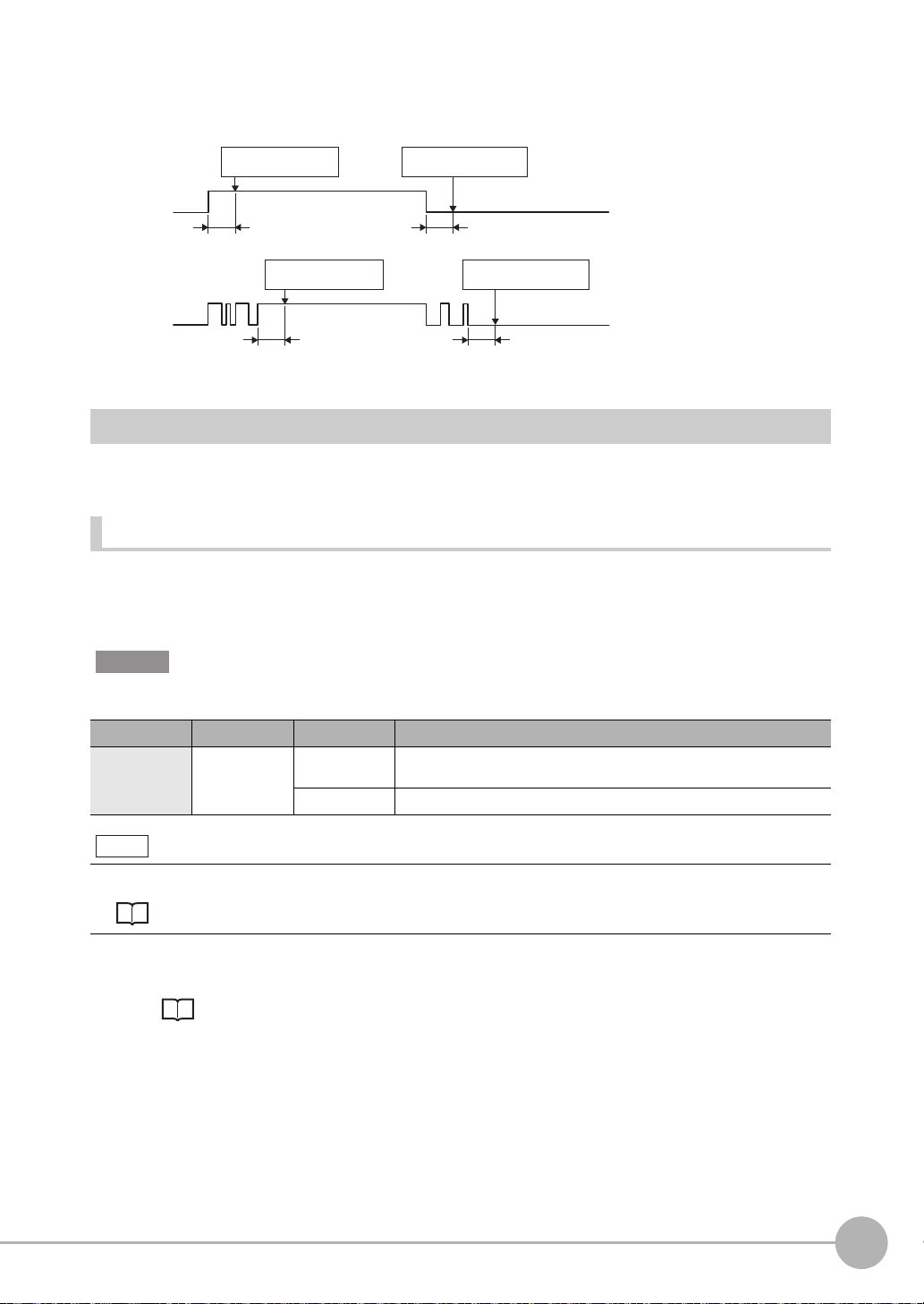
Example) When the filter setting value is 100μs (default value)
As an ON state persists for 100μs, an ON or OFF state of TIMING signal is detected. Therefore, a delay in the
detection of TIMING signal occurs for a period of time equivalent to the set filter value.
Without chattering
TIMING
With chattering
TIMING
ON
OFF
ON
OFF
ON state is detected as ON
state persists for 100µs.
100µs
ON state is detected as ON
state persists for 100µs.
100µs 100µs
OFF state is detected as OFF
state persists for 100µs.
100µs
OFF state is detected as OFF
state persists for 100µs.
Settings for Analog Output
The following describes the settings for outputting the current measurement results from the analog output of
the analog output terminal block.
Setting the analog output destination
With analog output, the measurement re sults can be outp ut con v erted to a current from 4 to 20 mA or a v oltage
from -10 to +10 V.
Selects which to output, the current or the voltage.
2
Parallel I/O Connection
Important
The same output destination is set for all banks. The output destination cannot be set separately for individual banks.
Item Setting item Setting value Description
Sensor settings Analog output Voltage output
(default value)
Current output Current output
Voltage output
Note
The analog output destination can also be set with key operations on the Sensor Controller.
Setting the analog output destination p.160
1 Set the operating mode to the FUNC mode.
Displacement Sensor ZW-8000/7000/5000 series Confocal Fiber Type Displacement Sensor
User's Manual (Z362) "3-2 Switching operation modes"
ZW-8000/7000/5000
User’s Manual for Communications Settings
Parallel I/O Connection
23
Page 26

Multi View Explore : [Device Group] | [(Sensor Name)] | [System] |
[System Data] (double-click)
→ Edit pane : [Sensor settings] icon ( )
2 Select the output destination from [Analog
output].
Important
When satisfies the following conditions, the analog output is disabled. A clamp value is output.
• Measurement cycle is 40 µs or less.
• EtherCAT communication is selected in the Fieldbus.
24
Parallel I/O Connection
User’s Manual for Communications Settings
ZW-8000/7000/5000
Page 27

Assigning Analog Output
Set the task for which to output the result s as analog.
Item Setting item Setting value Description
Analog output Output object None/TASK1/TASK2/TASK3/
TASK4
Select the task to output as analog.
1 Set the operating mode to the FUNC mode.
Displacement Sensor ZW-8000/7000/5000 series Confocal Fiber Type Displacement Sensor
User's Manual (Z362) "3-2 Switching operation modes"
Multi View Explore : [Bank Gr oup] | [(Bank Data Name)] (double click)
→ Edit pane : [I/O Settings] icon ( )
→ I/O Setting Screen : [Analog output]
2 Select the task from [Output object].
You can select from the above setting values.
None/TASK1/TASK2/TASK3/TASK4
2
Parallel I/O Connection
Note
Analog output can also be assigned with key operations on the Sensor Controller.
Assigning Analog Output p.161
ZW-8000/7000/5000
User’s Manual for Communications Settings
Parallel I/O Connection
25
Page 28
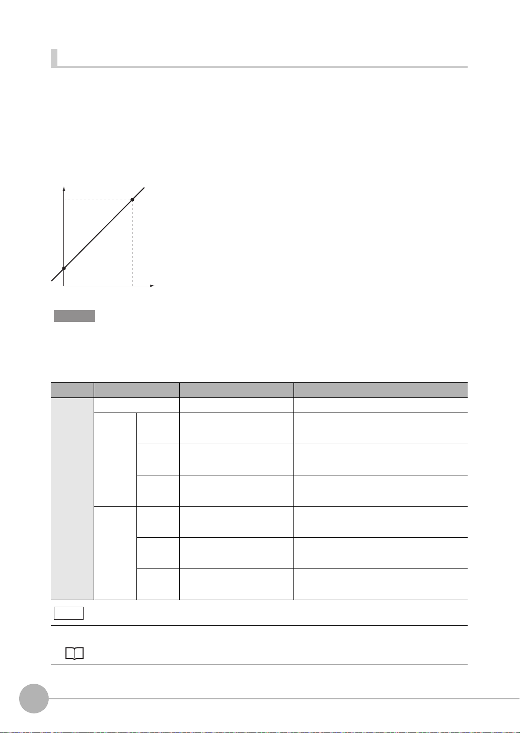
Setting Monitor Focus
With analog output, the relationship between the output value and measured value to be displ ayed can be set
as desired to convert the measurement result to 4 to 20 mA current or -10 to +10 V voltage before output.
Set the focus to match the connected external device.
The output range can be set by entering the output value for the current or voltage values for any two points.
Example: When setting 4 mA output (1st point) for measured value of 0 mm and 20 mA output for measured
value of 1 mm (2nd point) (current output)
Output current
(mA)
20
4
0
Point 1
0
Point 2
1
Measured value
(mm)
Important
• Separate the two specified points by at least 1% of the rated measuring range of the connected Sensor Head or 40
μm.
• After executing functions that add/subtract the span and offset values to/from the measurement value
, execute the
monitor focus.
Item Setting item Setting value Description
Monitor
focus
Monitor focus ON/OFF (default value) Sets monitor focus ON/OFF.
Point1 Distance
Point2 Distance
value
Current
output value
Voltage
output value
value
Current
output value
Voltage
output value
-999.999999 to 999.999999 [mm] Sets the reference measured value for output.
4 (default value) to 20 [mA] When the analog output destination is set to current,
-10 (default value) to 10 [V] When the analog output destination is set to v oltage,
-999.999999 to 999.999999 [mm] Sets the reference measured value for output.
4 (default value) to 20 [mA] When the analog output destination is set to current,
-10 (default value) to 10 [V] When the analog output destination is set to v oltage,
The default setting diff ers depending on the Sensor
Head.
sets the current to be output when the distance valu e is
measured.
sets the voltage to be output when the distance value
is measured.
The default setting diff ers depending on the Sensor
Head.
sets the current to be output when the distance valu e is
measured.
sets the voltage to be output when the distance value
is measured.
Note
The monitor focus can also be set with key operations on the Sensor Controller.
Setting Monitor Focus p.161
26
Parallel I/O Connection
User’s Manual for Communications Settings
ZW-8000/7000/5000
Page 29

1 Set the operating mode to the FUNC mode.
Displacement Sensor ZW-8000/7000/5000 series Confocal Fiber Type Displacement Sensor
User's Manual (Z362) "3-2 Switching operation modes"
Multi View Explore : [Device Group] | [(Sensor Name)] | [Bank Group] |
[(Bank Data Name)] (double click)
→ Edit pane : [I/O Settings] icon ( )
→ I/O Setting Screen : [Analog output]
2 Select ON from [Monitor Focus].
3 Enter the [Distance] and [Output value] at
[Point1].
4 Likewise, enter the [Distance] and [Output
value] at [Point2].
Adjusting the analog output value
2
Parallel I/O Connection
Discrepancies may occur between the current value/voltage value output as analog set on the Sensor
Controller and the current value/voltage value actually measured due to the conditions for the connected
external device or other factors.
The analog output adjustment function can be used to correct this discrepancy.
The output values are corrected by entering the adjustment value for the current or voltage values for any two
points.
Important
Set the output destination and select either current or voltage output beforehand. Also, connect the analog output
signal line to an external ammeter or voltmeter.
Item Setting item Setting value Description
Analog out-
put adjustment
Analog output adjustment ON/OFF (default value) Set analog output correction ON/OFF.
Point1 Reference value
Point2 Reference value
(current/value)
adjustment value -999 to 999 Sets the adjustment value when the reference value is
(current/value)
adjustment value -999 to 999 Sets the adjustment value when the reference value is
4 to 20 [mA]/-10 to 10 [V] Sets the current or voltage to be used as the correction
4 to 20 [mA]/-10 to 10 [V] Sets the current or voltage to be used as the correction
reference in the entry field on the left.
measured in the entry field on the right.
reference in the entry field on the left.
measured in the entry field on the right.
ZW-8000/7000/5000
User’s Manual for Communications Settings
Parallel I/O Connection
27
Page 30

1 Set the operating mode to the FUNC mode.
Displacement Sensor ZW-8000/7000/5000 series Confocal Fiber Type Displacement Sensor
User's Manual (Z362) "3-2 Switching operation modes"
Multi View Explore : [Device Group] | [(Sensor Name)] | [Bank Group] |
[(Bank Data Name)] (double click)
→ Edit pane : [I/O Settings] icon ( )
→ I/O Setting Screen : [Analog output]
2 Select ON from [Analog output adjustment].
Important
This setting is allowable only when Online.
3 Click [Setting].
The “Analog Output Adjust” popup menu
appears.
4 Enter the [Distance] and [Output value] at
[Point1], and click [Output].
5 Likewise, enter the [Distance] and [Output
value] at [Point2], and click [Output].
6 Click [Setting].
Note
Analog output values can also be adjusted with key operations on the Sensor Controller.
Adjusting the analog output value p.163
28
Parallel I/O Connection
User’s Manual for Communications Settings
ZW-8000/7000/5000
Page 31

Settings for Judgment Output
The following describes t he settings for outputting the judgment results from the judgmen t output of th e 32-pole
extension connector.
Assigning judgment output
Set the task for which to output the judgment results.
The judgment results for the selected task are output from the following output terminals of the 32-pole
extension connector.
HIGH/PASS/LOW
Item Setting item Setting value Description
Judgment Output object TASK1/TASK2/TASK3/TASK4 Select the task for which to output the judgment result.
1 Set the operating mode to the FUNC mode.
Displacement Sensor ZW-8000/7000/5000 series Confocal Fiber Type Displacement Sensor
User's Manual (Z362) "3-2 Switching operation modes"
Multi View Explore : [Bank Group] | [(Bank Data Name)] (double click)
→ Edit pane : [I/O Settings] icon ( )
→ I/O Setting Screen : [Judgment]
2 Select the task from [Output object].
2
Parallel I/O Connection
Note
Judgment output can also be assigned with key operations on the Sensor Controller.
Assigning judgment output p.164
ZW-8000/7000/5000
User’s Manual for Communications Settings
Parallel I/O Connection
29
Page 32

Setting Operation at Judgment Output
Set the hysteresis width of the judgment upper/lower limit values and judgment output timing.
Refer to “4-4 Setting Threshold Value” described in Displacement Sensor ZW-8000/7000/5000 series
Confocal Fiber T
Item Setting item Setting value Description
Judgment
output
Hysteresis width 0 to 99.9999mm Sets the hysteresis value (difference between operating point and
ype Displacement Sensor User’s Manual (Z362).
recovery point) of the judgment upper/lower limit values when HIGH/
PASS/LOW judgment is unstable near the boundary.
HIGH threshold
value
Measured value
LOW threshold
value
Hysteresis
(hysteresis width)
Action point
Return point
HIGH output
PASS output
LOW output
Satisfy the following conditions.
HIGH threshold value ≥ HIGH threshold value - Hysteresis (hysteresis
width) > LOW threshold value + Hysteresis (hysteresis width) ≥ LOW
threshold value
ON
OFF
ON
OFF
ON
OFF
Timer mode OFF (default value) Outputs the judgment as soon as the judgment result has been applied.
ON
OFF
ON
OFF
ON
OFF
Measured value
HIGH threshold
value
LOW threshold
value
HIGH output
PASS output
LOW output
Off Delay Delays the falling edge of the output s by the value set at [Timer Duration]
after the judgment result has been applied.
Measured value
HIGH threshold
value
LOW threshold
value
HIGH output
PASS output
LOW output
ON
OFF
ON
OFF
ON
OFF
: Timer time
30
Parallel I/O Connection
On Delay Delays the rising edge of the outputs by the value set at [Timer Duration]
after the judgment result has been applied.
HIGH threshold
value
LOW threshold
value
HIGH output
PASS output
LOW output
Measured value
ON
OFF
ON
OFF
ON
OFF
User’s Manual for Communications Settings
: Timer time
ZW-8000/7000/5000
Page 33

Item Setting item Setting value Description
Judgment
output
Timer mode One Shot When the judgment result is turned ON, output by the value set as [Timer
Timer time 1 (default value) to
5000 [ms]
Duration].
ON
OFF
ON
OFF
ON
OFF
Measured value
HIGH threshold
value
LOW threshold
value
HIGH output
PASS output
LOW output
Sets the timer duration when the timer mode is other than OFF.
1 Set the operating mode to the FUNC mode.
Displacement Sensor ZW-8000/7000/5000 series Confocal Fiber Type Displacement Sensor
User's Manual (Z362) "3-2 Switching operation modes"
Multi View Explore : [Bank Group] | [(Bank Data Name)] (double click)
→ Edit pane : [I/O Settings] icon ( )
→ I/O Setting Screen : [Judgment]
2 Set [Hysteresis Width].
3 Select the judgment output timing to match
operation of the external device from [Timer
mode].
4 Sets [Timer time].
: Timer time
2
Parallel I/O Connection
Note
The operations for judgment output can also be set with key operations on the Sensor Controller.
Setting Operation at Judgment Output p.165
Important
• The timer mode cannot be used when the measurement mode is external/PDO synchronous measurement mode.
• Timer time shall be a value rounded up by Measurement Cycle Time un
it.
• When 2 area mode is selected, minimum value shall be doubled Measurement Cycle.
ZW-8000/7000/5000
User’s Manual for Communications Settings
Parallel I/O Connection
31
Page 34

Settings for Bank Control
This section describes the settings for controlling banks by using parallel I/O.
Selecting banks
The bank is selected in combinations of the bank select input signals (BANK_SEL1 to 3).
Bank selection input 1
(BANK_SEL1)
OFF OFF OFF BANK1
ON OFF OFF BANK2
OFF ON OFF BANK3
ON ON OFF BANK4
OFF OFF ON BANK5
ON OFF ON BANK6
OFF ON ON BANK7
ON ON ON BANK8
Bank selection input 2
(BANK_SEL2)
Bank selection input 3
(BANK_SEL3)
Selected bank
Important
• At most it takes about 100ms to switch banks.
• During bank switching, the BUSY output becomes ON.
• If the bank mode is set to [JUDGE], the bank cannot be switched at the external
signal input because the number of
banks increases to 32.
Outputting the currently selected bank number
The currently selected bank number is output.
The output bank number depends on the combination of the bank number output signals (BANK_OUT1 to 3).
Bank number output 1
(BANK_OUT1)
OFF OFF OFF BANK1
ON OFF OFF BANK2
OFF ON OFF BANK3
ON ON OFF BANK4
OFF OFF ON BANK5
ON OFF ON BANK6
OFF ON ON BANK7
ON ON ON BANK8
Bank number output 2
(BANK_OUT2)
Bank number output 3
(BANK_OUT3)
Output bank
32
Parallel I/O Connection
User’s Manual for Communications Settings
ZW-8000/7000/5000
Page 35

Timing Chart
The following shows the timing charts when communication is performed with external devices.
Relationship between image capture duration and judgment output
Item Min. Max.
T0 Measuring cycle 60 μs (ZW-8000@)
T1 Exposure time 1 μsT0 - 3 μs
T2 Response time of jud gment output
T3 Refresh cycle of judgment output
T4 Response time of an alog output
T5 Refresh time of analog output
T6 Response delay time of Analog output − Output voltage: Approx 1.5 μs
*1 In 2 area mode, T0 is added to the values in the chart.
*2 P = 0
μs (ZW-7000@/5000@)
100
μs (ZW-8000@)
(1) (2) (3)
*1
*1
*1
*1
T0T1
20 μs (ZW-7000@)
80 μs (ZW-5000@)
− 250 μs + P
− T + 200 μs
− 80 μs (ZW-7000@/5000@)
− TO (1 area mode)
Depends on the set conditions
*2
200 μs (ZW-8000@)
2TO (2 area mode)
Current output: Approx 10 μs
2
Parallel I/O Connection
Exposure
Analog output
Judgment output
(HIGH/PASS/LOW)
T4
T2
T6
T5
T3
Explanation of operations
(1) During each measuring cycle, the light source is lit and exposure is started.
(2) After the end of exposure, measurement starts.
(3) After the end of measurement, the judgment result and the analog output are updated.
ZW-8000/7000/5000
User’s Manual for Communications Settings
Parallel I/O Connection
33
Page 36

Hold (peak/bottom/peak to peak/average)
Item Min. Max.
T18 RESET Minimum input time 2 × T0 + C*1 + 1100 μs −
T19 TIMING - BUSY ON maximum response
T20 TIMING minimum input time
T21 TIMING - BUSY OFF maximum response
T22 BUSY OFF - maximum response time of
T23 RESET maximum response time and
T39
*1 C = Filter width of input signal
*2 In 2 area mode, T0 is added to the values in the chart.
*3 P = 0
100
TIMING input
RESET input
BUSY output
Judgment output
(HIGH/PASS/LOW)
Analog output
*2
time
*2
*2
time
judgment/analog output
*2
RESET OFF-TIMING ON minimum time
TIMING OFF - RESET ON minimum time
μs (ZW-7000@/5000@)
μs (ZW-8000@)
(2) (3) (4)(5) (6)
T19
T20 T21
ON
OFF
ON
OFF
ON
OFF
T22
− TO + C*1+ P*3 + 80 μs
(When specify timing to measure
mode is selected)
2 × TO + C
(When specify timing to exposure
mode is selected)
T0 + C*1+ 20 μs
(Minimun OFF time is T0 + C
μs.)
*1
+ 60
−
− T0 + C*1+ P*3 + 300 μs
− 30 μs
− 2 × TO + C*1 + 3000 μs
*2
*2
TO + C*1+ 60 μs
(When specify timing to measure
mode is selected)
2 × TO + C
(When specify timing to exposure
mode is selected)
*1
+ 60 μs
T18T39
T23
−
(8) (7) (9)(1)
T23
*1
+ P*3 + 80 μs
Explanation of operations
(1) The TIMING input is turned ON.
(2) During the TIMING input minimum time, when the TIMING input is ON, sampling is started and the BUSY
output is turned ON.
(3) The TIMING input is turned OFF.
(4) After the TIMING input turns OFF, sampling is ended and the Judgment result and Analog output are
updated. The BUSY output is also turned OFF.
(5) After the Judgment result, and the analog output are updated.
(6) The RESET input is turned ON. If the RESET input is turned ON during the RESET input minimum time, the
measured value is reset.
(7) The judgment result and analog output are reset.
(8) The RESET input is turned OFF.
(9) After the RESET input is turned OFF, the TIMING input can be turned ON again.
34
Parallel I/O Connection
User’s Manual for Communications Settings
ZW-8000/7000/5000
Page 37

Important
RESET input
BUSY output
Judgment output
(HIGH/PASS/LOW)
Analog output
(1) (2) (4)(3)
ON
OFF
ON
OFF
(5)
T18
T24
T25
T22
• Judgment and Analog output may not be updated until BUSY is turned ON after Sampling procedure.
• When the setting for non-measurement is “CLAMP”, if the sampling value is an abnormal value or an undeter
*
, sampling is not executed. If sampling has been started, it is stopped. The output value is as follows.
value
• Hold the clamp value.
• To start and continue sampling even if a sampling value is an abnormal value or an undetermined value, set
“KEEP” as the non-measurement setting.
*: After the star
t of measurement, if measurement results are not obtained the n
umber of times required to take the
average, the measurement result is not applied.
*: The RESET of (6) through (8) can be omitted. When performing T
IMING input consecutively
, make sure that the
interval between TIMING inputs is the minimum OFF time of T20 or longer.
Hold (auto peak/auto bottom/auto peak-to-peak)
Item Min. Max.
T18 RESET minimum input time 2 × T0 + C*1 + 1100 μs −
T22 BUSY-OFF maximum response time of
T24 BUSY OFF maximum response time
T25 RESET - BUSY ON maximum response
*1 C = Filter width of input signal
*2 In 2 area mode, T0 is added to the values in the chart.
judgment/analog output
*2
time
− 0 μs (1 area mode)
*2
− T23
− T23
TO (2 area mode)
mined
2
Parallel I/O Connection
Explanation of operations
(1) The RESET input is turned ON. If the RESET input is turned ON during the RESET input minimum time, the
measured value is reset.
(2) Judgment result is reset. The BUSY output is turned OFF.
(3) After judgement result is reset, Analog output is reset.
(4) The RESET input is turned OFF.
(5) The BUSY output is turned ON.
Important
• Judgment and Analog output may not be updated until BUSY is turned OFF after Sampling procedure.
• When the setting for non-measurement is “CLAMP”, if the sampling value is an abnormal value or an undeter
*
, sampling is not executed. If sampling has been started, it is stopped. The output value is as follows.
value
mined
• Hold the clamp value.
• The BUSY signal is turned OFF.
• To start and continue sampling even if a sampling value is an abnormal value or an undetermined value, set
“KEE
*: After the star
average, the measurement result is not applied.
ZW-8000/7000/5000
User’s Manual for Communications Settings
P” as the non-measurement setting.
t of measurement, if measurement results are not obtained the n
umber of times required to take the
Parallel I/O Connection
35
Page 38

Hold (sampling)
Item Min. Max.
T18 RESET Minimum input time 2 × T0 + C*1 + 1100 μs −
T19 TIMING - BUSY ON maximum response
T20 TIMING minimum input time
T22 BUSY-ON maximum response time of judg-
*2
time
ment/analog output
*2
T23 RESET maximum response time and
RESET OFF-TIMING ON minimum time
T39 TIMING OFF - RESET ON minimum time*2TO + C*1 + 60 μs
*1 C = Filter width of input signal
*2 In 2 area mode, T0 is added to the values in the chart.
*3 P = 0
μs (ZW-7000@/5000@)
100
μs (ZW-8000@)
− TO + C*1 + P*3 + 80 μs
T0 + C*1 + 20 μs
(Minimum OFF time is T0 + C
60 μs.)
(When specify timing to measure
mode is selected)
2 × TO + C
(When specify timing to exposure
mode is selected)
−
*1
+
− 30 μs
− T0+C*1+3000 μs
*2
(When specify timing to measure
mode is selected)
2 × TO + C
(When specify timing to measure
mode is selected)
*1
+ 60 μs
*1
+ P*3+ 80 μs
TIMING input
RESET input
BUSY output
Judgment output
(HIGH/PASS/LOW)
Analog output
OFF
OFF
OFF
ON
ON
ON
(1) (2) (3)
T22
T19
T20
T39
(4)
T18
T23
(6) (5)
T23
(7)
Explanation of operations
(1) The TIMING input is turned ON.
(2) During the TIMING input minimum time, when the TIMING input is ON, sampling is started and the BUSY
output is turned ON. The measurement result is sampled and the judgment result is output.
(3) After the Judgment result, and the analog output are updated.
(4) The RESET input is turned ON. If the RESET input is turned ON during the RESET input minimum time, the
measured value is reset.
(5) The judgment result and the analog output are reset.
(6) The RESET input is turned OFF.
(7) After the RESET input is turned OFF, the TIMING input can be turned ON again.
Important
• Judgment and Analog output may not be updated until BUSY is turned OFF after Sampling procedure.
• When the setting for non-measurement is “CLAMP”, if the sampling value is an abnormal value or an undeter
*
, sampling is not executed. The output value is as follows.
value
mined
• Hold the clamp value.
36
Parallel I/O Connection
User’s Manual for Communications Settings
ZW-8000/7000/5000
Page 39

• The BUSY signal is not turned ON.
*: After the start of measurement, if measurement results are not obtained the n
umber of times required to take the
average, the measurement result is not applied.
*: The RESET of (6) through (8) can be omitted. When performing T
IMING input consecutively
, make sure that the
interval between TIMING inputs is the minimum OFF time of T20 or longer.
Bank Switching
Item Min. Max.
T7 Input response time − 200 ms
T8 Bank switching time − 100 ms
T9 Measurement start response time − Depends on the set conditions
T10 Maximum response time of judgement ON − Depends on the set conditions
2
Parallel I/O Connection
T8
(3) (4) (5)
T9 T10
BANK_SEL input
(BANK_SEL1/2/3)
BANK_OUT output
(BANK_OUT1/2/3)
BUSY output
ENABLE output
STABILITY output
JUDGMENT output
㸦HIGH/PASS/LOW㸧
TASKSTAT output
OFF
OFF
OFF
OFF
OFF
(1) (2)
T7
ON
ON
ON
ON
ON
Explanation of operations
(1) The BANK_SEL signal is switched to the bank nu mber to switch to.
(2) After the input response time, the measurement stops and the B USY output is turned ON, The ENABLE
output, STABILITY output, HIGH/PASS/LOW output, and TASKSTAT output are turned OFF at the same
time.
(3) After bank switching ends, the BUSY output is turned OFF and the BANK_ OUT output is switched.
(4) Measurement is restarted and the ENABLE output, STABILITY output is turned ON.
(5) When the measurement result is applied, the HIGH/PASS/LOW output and TASKSTAT output turn ON.
Important
Under the following conditions, the sensor controller display section does not change in conjunction with the output
signal and will continue to display the previous measurement state.
• When external synchronization measurement mode is set and TRIG input is not on.
• When the PDO syn
chronous measurement mode is set and EtherCAT is not established.
ZW-8000/7000/5000
User’s Manual for Communications Settings
Parallel I/O Connection
37
Page 40

LIGHT OFF
Item Min. Max.
T9 LIGHT OFF - ENABLE OFF maximum response
T10 LIGHT OFF minimum input time T0 + C*1 + 20 μs
T11 LIGHT OFF - ENABLE ON maximum response time − 2 × T0 + C*1 + P*2 + 150 μs
*1 C = Filter width of input signal
*2 P = 0
LIGHT OFF input
ENABLE output
time
μs (ZW-7000@/5000@)
100
μs (ZW-8000@)
ON
OFF
ON
OFF
(1) (2) (3) (4)
T10
T9
T11
Explanation of operations
(1) The LIGHT OFF input is turned ON.
(2) After the LIGHT OFF input is turned ON, the light source is turned OFF and the ENABLE output is turned
OFF.
(3) The LIGHT OFF input is turned OFF.
(4) After the LIGHT OFF input is turned OFF, the light source is turned ON and the ENABLE output is turned
ON.
− 2 × T0 + C*1 + P*2 + 300 μs
(Minimum OFF time is T0 +
*1
+ 60 μs.)
C
−
Zero reset
Item Min. Max.
T7 Input response time − 3 ms + T0 × 2
T13 ZERO input time 50 ms 0.8 s
T14 ZERO input cancel time 1s −
(4)
T14
(5)
ZERO input
Judgment output
(HIGH/PASS/LOW)
OFF
(1) (2)
T13 T7
ON
(3)
Explanation of operations
(1) The ZERO input is turned ON.
(2) After the ZERO input time, the ZERO input is turned OFF.
(3) After the ZERO input is turned OFF, the zero reset is executed and the judgment results refl ected in the
measurement results are output.
(4) The ZERO input is turned ON.
(5) After at least the cancel time of ZERO input has passed, the zero reset is cancelled.
38
Parallel I/O Connection
User’s Manual for Communications Settings
ZW-8000/7000/5000
Page 41

Operating Mode Switching
Item Min. Max.
T3 Response time of an alog output − T0 + 20 μs
T9 Measurement start response time − Depends on the set conditions
(1) (2) (3) (4)
T3
MODE
BUSY output
ENABLE output
Judgment output
(HIGH/PASS/LOW)
Analog output
OFF
OFF
ON
ON
RUN FUN RUN
All OFF
CLAMP
Explanation of operations
(1) After the mode is switched from RUN to FUNC mode, the BUSY output and ENABLE output are turned
OFF. The judgment outputs all go OFF.
(2) The response time of analog output after the BUSY output is turned ON, the analog output is output
clamped.
(3) After the mode is switched from the FUNC mode to the RUN mode, the BUSY output is turned OFF.
(4) Measurement is restarted and the ENABLE signal is turned ON, then the measurement results are output.
T9
2
Parallel I/O Connection
Important
Under the following conditions, the sensor controller display section does not change in conjunction with the output
signal and will continue to display the previous measurement state.
• When external synchronization measurement mode is set a
• When the PDO syn
chronous measurement mode is set and EtherCAT is not established.
nd TRIG input is not on.
ZW-8000/7000/5000
User’s Manual for Communications Settings
Parallel I/O Connection
39
Page 42

Measurement cycle
Item Min. Max.
T26 SYNC ON - SYNCFLG_ON maximum response
T27 SYNC_OFF - SYNCFLG_OFF maximum
T28 Response time when restart to capture after
T37 SYNCFLG_ON - SYNC_OFF time 0 μs −
T38 Minimum SYNC cycle T0 + T26 + T27 + T37 −
*1 C = Filter width of input signal
*2 P = 0
time
response time
SYNC input
μs (ZW-7000@/5000@)
200
μs (ZW-8000@)
SYNC input
(1) (3)(2) (4) (5)
T26
− T0 + C*1 + P*2 + 130 μs
− T0 + C*1 + P*2 + 250 μs
− T0 + C*1 + 70 μs
T27T37
SYNCFLG output
Image capture duration
measurement sensor 1
Image capture duration
measurement sensor 2
T28
T38
T0
Explanation of operations
(1) Turns ON SYNC input
(2) After SYNC input was turned ON, the image capture completion signals from the 2 measurement sensors
synchronize and a measurement is performed.
(3) SYNCFLG output turns ON.
(4) The SYNC input is turned OFF.
(5) SYNCFLG output is turned OFF after SYNC input is turned OFF.
Example of minimum SYNC cycle
Measurement cycle T0 ZW-7000@/5000@ ZW-8000@
C = 5 μs C = 100 μs C = 5 μs C = 100 μs
20 μs 450 μs 640 μs 610 μs 800 μs
40 μs 510 μs 700 μs 670 μs 860 μs
60 μs 570 μs 760 μs 730 μs 920 μs
80 μs 630 μs 820 μs 790 μs 980 μs
160 μs 870 μs 1060 μs 1030 μs 1220 μs
250 μs 1140 μs 1330 μs 1300 μs 1490 μs
500 μs 1890 μs 2080 μs 2050 μs 2240 μs
40
Parallel I/O Connection
User’s Manual for Communications Settings
ZW-8000/7000/5000
Page 43

Internal logging
Item Min. Max.
T6 LOGGING ON - LOGSTAT ON maximum
T7 LOGGING minimum input time T0 + C*1 + 20 μs −
T8 LOGGING OFF - LOGSTAT OFF maximum
*1 C = Filter width of input signal
LOGGING input
LOGSTAT output
response time
response time
(1)(2)
ON
OFF
ON
OFF
(3) (4)
T6
T8
T7
Explanation of operations
(1) Turns ON LOGGING input.
(2) Internal logging starts when LOGSTAT output is turned ON after LOGGING input is turned ON.
(3) Turns OFF the LOGGING in pu t.
(4) Finishes the Internal logging when LOGSTAT output is turned OFF after LOGGING input is turned OFF.
However, if an insufficient logging memory occurs, turns ON the LOGERR output. The LOGERR output is
turns OFF simultaneously with the LOGGING input turned OFF.
− T0 + C*1 + 30 μs
− T0 + C*1 + 250 μs
2
Parallel I/O Connection
ZW-8000/7000/5000
User’s Manual for Communications Settings
Parallel I/O Connection
41
Page 44

External synchronous measurement mode
Item Min. Max.
T29 Minimum TRIG ON time C*1 + 20 μs −
T30 Minimum TRIG OFF time C*1 + 60 μs −
T31 Minimum TRIG cycle T29 + T30 −
T32 TRIG - TRIGBUSY response − C*1 + 30 μs
T33 TRIG_BUSY ON time T0 + 100 μs T0 + 200 μs
T34 TRIG - Judgment output response − T0 + T2 + T29
T35 TRIG - Analog output response − T0 + T4 + T29
T36 TRIG-Measurement cycle start time − T29
*1 C = Filter width of input signal
(1) (2) (3) (4) (5)
T29
T31
T30
TRIG input
T33
T32
TRIG BUSY output
T35
Analog output
Judgment output
(H, P, L, TSAK_STAT)
T34
T36
Image capture duration
T0
Explanation of operations
(1) Turns ON TRIG input.
(2) TRIG BUSY output turns ON and capturing images is started to perform a measurement.
(3) TRIG BUSY output turns OFF, allowing the next TRIG input to be received.
(4) After the measurement has been completed, the judgement result and analog output are updated.
(5) Image capture and measurement are not performed without TRIG input.
Example of minimum TRIG cycle
Measurement cycle T0 C = 5 μs C = 100 μs
20 μs 120 μs 280 μs
40 μs 140 μs 280 μs
80 μs 180 μs 280 μs
160 μs 260 μs 280 μs
250 μs 350 μs 350 μs
500 μs 500 μs 600 μs
42
Parallel I/O Connection
User’s Manual for Communications Settings
ZW-8000/7000/5000
Page 45

EtherCAT Connection
3-1 EtherCAT Connection . . . . . . . . . . . . . . . . . . . . . . . . . . . . . . . . . . . . . . 44
3
EtherCAT Connection
Page 46

3-1 EtherCAT Connection
Overview of EtherCAT Networks
EtherCA T (Et hernet Control Automati on Technology) is a high-performance industrial network system based on
Ethernet system and can realize faster and more efficient communications.
Each node achieves a short communications cycle time by transmitting Ethernet frames at high speed.
Furthermore, even though EtherCAT is a unique prot ocol, it offers excellent general-purpose applicability. For
example, you can use Ethernet cables because EtherCAT utilizes standard Ethernet technology for the
physical layer. And the effectiveness of EtherCAT can be fully utilized not only in large control systems that
require high processing speeds and system integrity, but also in small and medium control systems.
Features of EtherCAT
EtherCAT has the followin g features.
● Extremely high
It dramatically shortens the I/O response time from generation of input signals to transmission of output
signals.
method, it is possible to efficiently transmit a wide variety of data.
●
EtherCAT is an open network with extremely high compatibility with conventional Ethernet systems.
By fully utilizing the optimized Ethernet frame bandwidth to transfer data using a high-speed repeat
Extremely High Compatibility with Ethernet
-speed communications with speed of 100 Mbps
Structure of EtherCAT
EtherCAT does not send data to individual slave nodes on the network, instead, it passes Ethernet frames
through all of the slave nodes.
When frame passes through a slave node, the slave node reads and writes data in the areas allocated t o it in
the frames in a few nanoseconds.
Ethernet frames sent from the EtherCAT Master Unit go through all the EtherCAT Slave Units without stopping
on the way. Once they reach the final Slave Unit, they are sent back from the final Slave Unit, pass through all
Slave Units again, and return to the EtherCAT Master Unit.
With this structure, EtherCAT secures high-speed and real-time data transmission.
EtherCAT
Master Unit
Slave Unit Slave Unit
Data
OUT
IN
Slave Unit
44
EtherCAT Connection
Ethernet frame
•
Reading output data addressed to the local Slave Units
• Writing input data
User’s Manual for Communications Settings
ZW-8000/7000/5000
Page 47

It is the “EtherCAT datagram” stored directly in an Ethernet frame that exchanges data regularly between the
EtherCAT Master Unit and Slave Units.
Each “EtherCAT datagram” is configured with header (data length, including address of one or more Slave
Units, etc.), data, working counter (check bit).
When an Ethernet frame is compared to a “train”, an EtherCAT datagram can be considered as “railway car.”
Ethernet frame
Ethernet
header
EtherCAT
header
1st EtherCAT
datagram
Ethernet data (Maximum 1498 bytes)
2nd EtherCAT
datagram
1...n EtherCAT datagram
. . . . .
DataHeader
WKC
WKC : Working counter
CRC
EtherCAT frame
n th EtherCAT
datagram
3
EtherCAT Connection
ZW-8000/7000/5000
User’s Manual for Communications Settings
EtherCAT Connection
45
Page 48

Communications Types of EtherCAT
EtherCAT provides the following two types of communication functions.
PDO communications are always updating data per communication cycle on EtherCAT, while SDO
communications are processed in between those upda tes.
●
Process data communications functions (PDO communications)
This communicat
By mapping
communications among the EtherCAT Master Unit and Slave Units.
ion function is used to transfer process data in real time in a fixed-cycle.
logical process data space to each node by the EtherCAT Master Unit, it achieves fixed-cycle
EtherCAT Master Unit
Ethernet frame
Logic process data
.
.
.
Data a
.
.
.
Data b
Data c
.
.
.
Ethernet
header
Slave Unit
EtherCAT
header
1st EtherCAT
datagram
Slave Unit Slave Unit
2nd EtherCAT
datagram
3rd EtherCAT
datagram
Slave Unit
. . .
CRC
●
Mailbox communications functions (SDO communications)
It refers t
At any timing,
o message communications.
the EtherCAT Master Unit transmits commands to Sla ve Units and the Slave Units return
responses to the EtherCAT Master Unit.
It performs the following data communications:
• Read and write process data
• Slave Unit Settings
• Monitoring the slave unit state
46
EtherCAT Connection
User’s Manual for Communications Settings
ZW-8000/7000/5000
Page 49

● Synchronization with Distributed Clocks
A mechanism called a distributed clock (DC) is used to synchronize EtherCAT communications.
The DC mode is use
timing.
In DC mode, the master and slav es are synchronized by sharing the same clock.
Interruptions (Sync0) are generated in the slaves at precise intervals based on this clock.
Displacement Sensor control is carried out at this precise timing.
Communications Cycle (DC Cycle)
The communications cycle is determined by setting the Sync0 signal output cycle.
Set the Output cycle 125µs, or longer. For details on the setting procedure, refer to "Sysmac Studio Version 1
Operation Manual" (W504).
d for ZW-8000/7000/5000 series to perform highly accurate control of measurement start
3
EtherCAT Connection
ZW-8000/7000/5000
User’s Manual for Communications Settings
EtherCAT Connection
47
Page 50

Communication Meth ods f or Measure ment Sensor w hen Connecte d via EtherCAT
Communications between the EtherCAT master and the displacement sensor is performed over EtherCAT to
enable control from the master by control signals and data output after measured values are applied.
When the displacement sensor is connected to an NX/NJ series CPU Unit via EtherCAT, Sysmac Studio
(standard edition) is used to register the ZW to the EtherCAT slave configuration on the network configuration
edit pane.
For details on registr ation methods , refer to Sysmac Studio Version 1 Operation Manual (W504) “4-2 Controller
Configuration/Setting.”
Important
• Up to 32 measurement sensors can be connected via EtherCAT.
• If EtherCAT is set to enables to perform communications over EtherCAT
disabled and EtherNet/IP communications is no longer possible.
Setting Communications Specific ations (EtherCAT Communications) p.51
Communications method using process data objects (PDO)
● Control of displacement sensors by control/status signals
With EtherCAT communications, process dat a objects (PDO) are used to p erfo rm PDO communications (cyclic
communication
the master to the displacement sensor, status signals from the displacement sensor to the master, and
command responses to the I/O ports (or I/O memory)
*1: When connected to the NX/NJ series, “I/O ports” are used, and when connected to the CJ series, “I/O memory” is used. Explanations from
here on are for when the connection is to the NX/NJ series.
s). Control of the displacement sensor is performed by storing control signals/command from
(*1)
of the Controller.
, the EtherNet/IP communications setting is
Controller (master)
NX/NJ-series CPU Unit
I/O ports
Command area
Response area
Control signal,
Commands
TIMING input
Current bank settings
command, etc.
Displacement Sensor (slave)
Response
HOLDSTAT output
Command Response, etc.
EtherCAT communications
The Controller sends the instruction to the displacement sensor over EtherCAT by switching the cont rol signal
bit assigned with control to be executed to ON.
The displacement sensor executes the instruction, and updates the status signal bit according to the result to
return it over EtherCAT. ÅB
When instructions are exec ute d by control commands, control commands are sent to the displacement sensor
over EtherCAT by writing the control command, for example , to I/O port Command and then turning the control
command execution (EXE) bit ON.
The displacement sensor executes that control command, and returns the response to the Controller over
EtherCAT. The Controller stores the response to I/O port Response, fo r example.
48
EtherCAT Connection
User’s Manual for Communications Settings
ZW-8000/7000/5000
Page 51

● Output of displacement sensor measurement data to output area
The measurement data of all tasks is automatically output from the displacement sensor to I/O port
Measurement Value of Output data1 to 4 immediately after the measured value is applied.
This enables the measurement results of all tasks to be easily handed over to the Controller.
Controller (master) Displacement sensor
NX/NJ-series CPU Unit
After applying
measured value
I/O ports
(slave)
Output area
Data
Automatically output 4
measured data, etc.
EtherCAT communications
With EtherCAT communications, communications is performed via the I/O ports of the following four area on
the Controller. Sysmac error status area I/O ports are used only when an NX/NJ series CPU unit is connected
as the master.
Control by control/
status signals
(1) I/O ports of instruction
area
(2) I/O ports of response
area
Data output after applica-
(3) I/O ports of output area
tion of measured value
For error status (4) I/O ports of Sysmac
error status area
I/O ports to which the user writes control signals to be
executed on the displacement sensor and control commands
I/O ports to which the displacement sensor writes the
control signals written to the instruction area and the
result of executing control commands
I/O ports to which the displacement sensor writes the output data accompanying measurement after application of
the measured value
I/O ports to which the displacement sensor writes the
error status
3
EtherCAT Connection
ZW-8000/7000/5000
User’s Manual for Communications Settings
EtherCAT Connection
49
Page 52

Controller (master)
Command area I/O port
The following control commands are
written to the Displacement Sensor.
Command
Displacement Sensor (slave)
The control commands written to the I/O
ports in the Command Area are
executed.
Command/
response
communications
Data output
after
measurements
Error status
Response area I/O port
The execution results from the
Displacement Sensor are written
here.
Output area I/O port
Output data from the Displacement
Sensor is written here.
I/O Ports in Sysmac Error Status Area
Error status information from the
Displacement Sensor is written here.
Response
Execution
The results of execution are written to
the I/O ports in the Response Area.
After applying measured value
Measurement results are written to the
I/O ports in the Data Output Area.
Error status information is written to the
I/O ports in the Sysmac Error Status Area.
●
Sysmac error status
Communications method using service data objects (SDO)
The ZW series supports SDO communications. SDO communications is used for set ting objects and
monitoring the status of the ZW series. Objects can be set or the status monitored by reading and writing data
to entries in the object dictionary of the host Controller.
50
EtherCAT Connection
User’s Manual for Communications Settings
ZW-8000/7000/5000
Page 53

Setting Communications Specifications (EtherCAT Communications)
Setting default settings for EtherCAT communications
Set the default settings for EtherCAT communications.
Item Description Range
Fieldbus Select whether to use EtherNet/IP communications or EtherCAT
GATE signal ON time Set the output time of the GATE signal for notifying the timing that the
communications.
measured value was updated when hold is output.
OFF
EtherNet/IP
EtherCAT (default value)
0 to 100ms
1ms (default value)
Multi View Explore : [Device Group] | [(Sensor Name)] | [System] |
[System Data] (double-click)
→ Edit pane : [Ethernet Communications Settings] icon ( )
1 Set the fieldbus settings.
Select [EtherCAT] at [Fieldbu s].
2 Set the output time of the GATE signal.
Set the value at [GATE signal ON time].
Note
The setting of default settings for EtherCAT communications can also be set by the operating keys on the Sensor
Controller.
Setting Fieldbus p.175
Setting GATE Signal ON Time p.176
Important
• This setting contemns will be effected when launch the Sensor Controller.
• Save the setting data after changing this setting, and then restart to the Sensor Con
troller.
3
EtherCAT Connection
ZW-8000/7000/5000
User’s Manual for Communications Settings
EtherCAT Connection
51
Page 54

List of I/O Ports for Each Area (PDO Mapping) and Memory Assignments
When connection destination is an NX/NJ series Controller
This section describes the respective I/ O ports of the instruction area, response area, output area, and Sysmac
error status area.
● I/O ports of instruction area
Controller (master) → Displacement sensor (slave)
I/O port name Signal Signal name Function
Sensor Head Control
Signal1
EXE EXE Control command
SYNC SYNC Measurement
ERCLR ERCLR Error clear Turns ON when the displacement sensor error signal
Sensor Head Control
Signal2
TIMING TIMING Timing Turns ON when the user (Controller) instructs start of hold
RESET RESET Reset Turns ON when the user (Controller) instructs judgment
LIGHTOFF LIGHTOFF Light metering OFF Turns ON when the user (Controller) instructs logical beam
ZERO_T1 to 4 ZERO_T1 to 4 Zero reset execution Turns ON when the user (Controller) instructs execution of
ZEROCLR_T1 to 4 ZEROCLR_T1 to 4 Zero reset cancel Turns ON when the user (Controller) instructs zero reset
Sensor head control
signal1
execution
synchronous start
Sensor head control
signal2
T u rns ON when the user (Controller) in structs execution of
control commands to the displacement sensor.
(Turns ON after the control command code and
parameters are set.)
Is returned to OFF on condition (input condition) that the
user (Controller) turns the control command completion
signal (FLG signal) from the displacement sensor ON.
Turns ON when the user (Controller) instructs
measurement synchronization to the displacement sensor .
Is returned to OFF on condition (input condition) that the
user (Controller) turns the measurement synchronization
completion signal (SYNCFLG signal) ON.
(ERR signal) turns OFF.
Is returned to OFF on condition (input condition) that the
user (Controller) turns the error signal (ERR signal) OFF.
sampling to the displaceme nt sensor.
T urns OFF when the user (Contro ller) instructs end of hold
sampling to the displaceme nt sensor.
processing and output reset to the displacement sensor.
If the hold function is used, the state in effect before the
hold function was set will be restored.
Turns OFF when the user (Controller) ends judgment
processing and output reset to the displacement sensor.
OFF to the displacement sensor.
Turns OFF wh en th e u s e r (C on t roller) instruct s logical
beam ON to the displacement sensor.
zero reset of TASK1 to 4 to the displacement sensor.
Is returned to OFF on condition (input condition) that the
user (Controller) turns the zero reset completion signal
(ZEROSTAT signal) from the displacement sensor ON.
cancel of TASK1 to 4 to the displacement sensor.
Is returned to OFF on condition (input condition) that the
user (Controller) turns the zero reset completion signal
(ZEROSTAT signal) from the displacement sensor OFF.
52
EtherCAT Connection
User’s Manual for Communications Settings
ZW-8000/7000/5000
Page 55

I/O port name Signal Signal name Function
Command Command code Command code Stores the command code.
Command Parameter 1
to 3
Parameter 1-3 Command parameter Stores the command parameter.
Note
• In the FUNC mode, control signals other than ERCLR and LIGHTOFF cannot be executed.
• Multiple control signals cannot be executed in the same cycle. Note, however, that when zero reset execution/
cancellation are performed simultaneously on multiple tasks, ZERO_T1 to 4 and ZEROCLR_T1 to 4 can be
executed in the same cycle. Also, all control signals can be executed in the same cycle on ERCLR and
LIGHTOFF.
• When the status of control signals differs from that of the input status of parallel I/O, processing is ex ecuted of one
of the statuses is ON.
• SYNC can be used only in EtherCAT communications. It cannot be used in EtherNet/IP communications.
3
● I/O ports of response area
Displacement sensor (slave) → Controller (master)
I/O port name Signal Signal name Function
Sensor Head Status
Signal1
FLG FLG Control command
SYNCFLG SYNCFLG Measurement
READY READY Ready Turns OFF when the displacement sensor cannot execute
SEQUENCE SEQUENCE Measurement e x ecution
RUN RUN Run screen Turns ON when the displacement sensor is in the RUN
ERR ERR Error Turns ON when a displacement sensor error is detected.
BANKOUT_A to E BANKOUT_A to E Current bank number This outputs the currently specified bank number.
Sensor Head Status
Signal1
completion
synchronization
completion
status
Turns ON when the displacement sensor completes
control command execution.
(T urns ON after the control comman d code, response co de
and response status are stored.)
Automatically turns OFF if the control command execution
signal (EXE signal) from the user (Controller) turns OFF.
Turns ON when the displacement sensor executes
measurement synchronization processing and the state
changes to one where normal measured values can be
output.
Automatically turns OFF if the measurement
synchronization signal (SYNC signal) from the user
(Controller) turns OFF.
control commands or measurement synchronization
processing.
Turns ON when the displacement sensor can execute
control commands or measurement synchronization
processing.
Turns ON from OFF when the Vision Sensor starts to
capture at the timing of the Sync0 of EtherCAT.
Turns OFF from ON when the output processing which
outputs the measurement result to the output area is
completed.
mode.
Turns OFF when the displacement sensor is in the FUNC
mode.
Turns OFF when the displacement sensor is normal.
After it turns ON, it never turns OFF until the error clear
signal (ERCLR signal) from the user (Controller) turns ON.
It expresses the bank number in combinations of
BANKOUTx_A to E.
(For details of combinations, see .)
Note
EtherCAT Connection
ZW-8000/7000/5000
User’s Manual for Communications Settings
EtherCAT Connection
53
Page 56

I/O port name Signal Signal name Function
Sensor Head Status
Signal2
HOLDSTAT HOLDSTAT Hold execution status Turns ON when the displacement sensor is in the hold
RESETSTAT RESETSTAT Reset execution state Turns ON when the displacement sensor is in the reset
LIGHT LIGHT Logical beam lighting
STABILITY STABILITY Measurement position Turns ON when the measured value is in the measuring
ENABLE ENABLE Measurement state Turns ON when the displacement sensor is ready for
GATE GATE Data output completed Turns ON when the displacement sensor completes
OR OR Overall judgment result Turns ON when even one of the judgment result of the
HIGH_T1 to 4 HIGH_T1-4 HIGH output Turns ON when the judgment result of the displacement
PASS_T1 to 4 PASS_T1-4 PASS Output Turns ON when the judgment result of the displacement
LOW_T1 to 4 LOW_T1-4 LOW output Turns ON when the judgment result of the displacement
ZEROSTAT_T1 to 4 ZEROSTAT_T1-4 Zero reset state Turns ON when the displacement sensor TASK1 to 4 is in
T ASKSTAT_T1 to 4 TASK_STATUS1-4 T A SK status T urns ON when the measurement da ta is finaliz ed for each
Response Command code Command code The executed command code is returned.
Response Code Response code Response code The response code of the executed command is stored.
Response Data Response data Response data The response data of the executed command is stored.
Sensor Head Status
Signal2
state
sampling period.
Turns OFF when the displacement sensor is outside the
hold sampling period.
execution state.
Turns OFF when the displacement sensor is in the reset
non-execution state.
Turns ON when the logical beam is lit.
Turns OFF when the logical beam is out.
range.
Turns OFF when the measured value is outside the
measuring range.
measurement.
T urns OFF when the displacement sensor cannot measure
(excessive or insufficient rece iv ed light, outside measuring
range, Calibration ROM not mounted, during FUNC mode
non-measurement).
control data output when hold is set.
The displacement sensor automatically turns OFF one
Gate period after turning ON.
displacement sensor TASK1 to 4 is other than PASS.
Turns OFF when all of the judgment result of the
displacement sensor TASK1 to 4 is PASS.
sensor TASK1 to 4 is HIGH (HIGH threshold < measured
value).
Turns OFF when the judgment result of the displacement
sensor TASK1 to 4 is other than HIGH.
sensor TASK1 to 4 is PASS (LOW threshold ≤ measured
value ≤HIGH threshold).
Turns OFF when the judgment result of the displacement
sensor TASK1 to 4 is other than PASS.
sensor TASK1 to 4 is LOW (LOW threshold > measured
value).
Turns OFF when the judgment result of the displacement
sensor TASK1 to 4 is other than LOW.
the zero reset execution state.
T urns OFF when the displacement sensor TASK1 to 4 is in
the zero reset non-execution state.
TASK1 to 4.
54
EtherCAT Connection
User’s Manual for Communications Settings
ZW-8000/7000/5000
Page 57

Note
Bank number BANKOUTx_A BANKOUTx_B BANKOUTx_C BANKOUTx_D BANKOUTx_E
BANK1 OFF OFF OFF OFF OFF
BANK2 ON OFF OFF OFF OFF
BANK3 OFF ON OFF OFF OFF
BANK4ONONOFFOFFOFF
BANK5 OFF OFF ON OFF OFF
BANK6 ON OFF ON OFF OFF
BANK7 OFF ON ON OFF OFF
BANK8ONONONOFFOFF
BANK9 OFF OFF OFF ON OFF
BANK10 ON OFF OFF ON OFF
BANK11 OFF ON OFF ON OFF
BANK12 ON ON OFF ON OFF
BANK13 OFF OFF ON ON OFF
BANK14 ON OFF ON ON OFF
BANK15OFFONONONOFF
BANK16 ON ON ON ON OFF
BANK17OFFOFFOFFOFFON
BANK18 ON OFF OFF OFF ON
BANK19 OFF ON OFF OFF ON
BANK20 ON ON OFF OFF ON
BANK21 OFF OFF ON OFF ON
BANK22 ON OFF ON OFF ON
BANK23 OFF ON ON OFF ON
BANK24 ON ON ON OFF ON
BANK25OFFOFFOFFON ON
BANK26 ON OFF OFF ON ON
BANK27 OFF ON OFF ON ON
BANK28 ON ON OFF ON ON
BANK29 OFF OFF ON ON ON
BANK30 ON OFF ON ON ON
BANK31OFFONONONON
BANK32 ON ON ON ON ON
• The results of processing execution by parallel I/O also are reflected in the status signals.
• The table below shows the combinations of bank numbers and BANKOUTx_A to E.
(BANK9 to 32 are used only in the judgment value mode. In the normal mode, BANKOUTx_D to E are OFF at all
times.)
ZW-8000/7000/5000
User’s Manual for Communications Settings
EtherCAT Connection
3
EtherCAT Connection
55
Page 58

● I/O ports of output area
Displacement sensor (slave) → Controller (mas
I/O port name Signal Signal name Size of output data Function
Output Data1 Output Data1 OUT1 data 4 bytes The Measurement result of OUT1 is
Output Data2 Output Data2 OUT2 data 4 bytes The Measurement result of OUT2 is
Output Data3 Output Data3 OUT3 data 4 bytes The Measurement result of OUT3 is
Output Data4 Output Data4 OUT4 data 4 bytes The Measurement result of OUT4 is
ter)
output.
output.
output.
output.
● I/O ports of sysmac error status area
Displacement sensor (slave) → Controller (master)
The Sysmac error status is mapped only when the connection destination is the NX/NJ series.
I/O port name Signal Signal name Function
Sysmac Error Status Sysmac Error
Observation Observation Monitor error Turns ON when a monitor error occurs on the
Minor Fault Minor Fault Light fault level error T urns ON when a light fault level error occurs on the
Status
Sysmac error status Indicates the Sysmac error status.
displacement sensor.
displacement sensor.
56
EtherCAT Connection
User’s Manual for Communications Settings
ZW-8000/7000/5000
Page 59

Assigning Device Variables to I/O Ports (PDO Mapping)
When connected to an NX/NJ-series CPU Unit, the data for PDO communications in the Vision Sensor is
displayed with I/O port names on the Sysmac Studio. You can assign device variables to the I/O ports in the
Sysmac Studio I/O map to perform programming and monitoring.
Multi View Explore (Connected to NX/NJ-series CPU Unit): [Configurations and Setup] |
[I/O Map] (Double-click)
3
EtherCAT Connection
Right-click a slave or I/O port in the I/O map and select [Create Device Variable]. The device variable name is
automatically created as a combination of the device name and the I/O port name. You can also select an I/O
port and enter a variable name in the [Variable] column.
You can also select a registered variable from the variable table to use as a device variable. Refer to the
Sysmac Studio Version 1 Operation Manual (Cat. No. W504) for details on registering device variables.
ZW-8000/7000/5000
User’s Manual for Communications Settings
EtherCAT Connection
57
Page 60

When the connection destination is a CJ series PLC
This section describes the respectiv e area assign ments of the instruction area, resp onse area and o utput area.
● Instruction area
PLC (master) → Displacement sensor (slave)
Top
channel
15 14 13 12 11 10 9 8 7 6 5 4 3 2 1 0
Reserved Reserved Reserved Reserved Reserved Reserved Reserved Reserved Reserved Reserved Reserved Reserved Reserved Reserved
+0
Reserved Reserved Reserved Reserved Reserved Reserved Reserved Reserved Reserved Reserved Reserved Reserved Reserved Reserved Reserved
+1
Bit Description
SYNC EXE
ERCLR
Sensor Head
Control
signal1
(32bit)
Reserved Reserved Reserved Reserved Reserved Reserved Reserved Reserved Reserved Reserved Reserved Reserved Reserved
+2
Reserved Reserved Reserved Reserved Reserved Reserved Reserved Reserved ZERO-
+3
Reserved Reserved Reserved Reserved Reserved Reserved Reserved Reserved Reserved Reserved Reserved Reserved Reserved Reserved Reserved Reserved
+4
Reserved Reserved Reserved Reserved Reserved Reserved Reserved Reserved Reserved Reserved Reserved Reserved Reserved Reserved Reserved Reserved
+5
CLR_T4
ZERO-
CLR_T3
ZERO-
CLR_T2
ZERO-
CLR_T1
+6 Command code
+7
+8 Parameter 1
+9 Parameter 2
+10 Parameter 3
+11
LIGHT
RESET TIMING
OFF
ZERO_T4ZERO_T3ZERO_T2ZERO_
T1
Sensor Head
Control
signal2
(32bit)
Data
(parameter)
(32bit)
Command
code
(32bit)
Data
(parameter1)
(16bit)
Data
(parameter2)
(16bit)
Data
(parameter3)
(32bit)
Signal Signal name Function
EXE Control command execution Turns ON when the user (PLC) instructs execution of control commands t o the
displacement sensor.
(Turns ON after the control command code and parameters are set.)
Is returned to OFF on condition (input condition) that the user (PLC) turns the
control command completion signal (FLG signal) from the displacement
sensor ON.
SYNC* Measurement synchronous
start
Turns ON when the user (Controller) instructs measurement synchronization
to the displacement sensor.
Is returned to OFF on condition (input condition) that the user (Controller)
turns the measurement synchronization completion signal (SYNCFLG signal)
ON.
ERCLR Error clear Turns ON when the disp lacement sensor error si gnal (ERR signal) t urns OFF.
Is returned to OFF on condition (input condition) that the user (PLC) turns the
error signal (ERR signal) OFF.
TIMING Timing Turns ON when the user (PLC) instructs start of hold sampling to the
displacement sensor.
Turns OFF when the user (PLC) instructs end of hold sampling to the
displacement sensor.
RESET Reset Turns ON when the user (PLC) instructs judgment processing and output
reset to the displacement sensor.
If the hold function is used, the state in effect before the hold function was set
will be restored.
Turns OFF when the user (PLC) ends judgment processing and output reset
to the displacement sensor.
58
EtherCAT Connection
User’s Manual for Communications Settings
ZW-8000/7000/5000
Page 61

Signal Signal name Function
LIGHTOFF Light metering OFF Turns ON when the user (PLC) instructs logical beam OFF to the
displacement sensor.
Turns OFF when the user (PLC) instructs logical beam ON to the
displacement sensor.
ZERO_T1 to 4 Zero reset execution Turns ON when the user (PLC) instructs execution of zero reset of TASK1 to 4
to the displacement sensor.
Is returned to OFF on condition (input condition) that the user (PLC) turns the
zero reset completion signal (ZEROSTAT signal) from the displacement
sensor ON.
ZEROCLR_T1 to 4 Zero reset cancel Turns ON when the user (PLC) instructs zero reset cancel of TASK1 to 4 to
the displacement sensor.
Is returned to OFF on condition (input condition) that the user (PLC) turns the
zero reset completion signal (ZEROSTAT signal) from the displacement
sensor OFF.
Command code Command code Stores the command co de.
Parameter 1-3 Command parameter Stores the command parameter.
* SYNC signal's area is disabled in External synchronous measurement mode.
Note
• In the FUNC mode, control signals other than ERCLR and LIGHTOFF cannot be executed.
• Multiple control signals cannot be executed in the same cycle. Note, however, that when zero reset execution/
cancellation are performed simultaneously on multiple tasks, ZERO_T1 to 4 and ZEROCLR_T1 to 4 can be
executed in the same cycle.
• When the status of control signals differs from that of the input status of parallel I/O, processing is ex ecuted of one
of the statuses is ON.
• TRIG input signal, which is newly added to the ZW-8000/7000/5000 can be controlled from I/O signals. The input
from PDO map is not possible.
3
EtherCAT Connection
● Response area
Displacement sensor (slave) → PLC (master)
Top
channel
15 14 13 12 11 10 9 8 7 6 5 4 3 2 1 0
BANK1_EBANK1_DBANK1_CBANK1_BBANK1_AReserved Reserved Reserved Reserved Reserved Reserved RUN SEQUENCEREADY
+0
Reserved Reserved Reserved Reserved Reserved Reserved Reserved Reserved Reserved Reserved Reserved Reserved Reserved Reserved Reserved ERR
+1
Reserved Reserved Reserved Reserved TASKST
+2
LOW_T4PASS_T4HIGH_T4LOW_T3P ASS _T3HIGH_T3LOW_T2P ASS _T2HIGH_T2LOW_T1P ASS _T1HIGH_T1ZERO
+3
Reserved Reserved Reserved Reserved Reserved Reserved Reserved Reserved Reserved Reserved Reserved Reserved Reserved Reserved Reserved Reserved
+4
Reserved Reserved Reserved Reserved Reserved Reserved Reserved Reserved Reserved Reserved Reserved Reserved Reserved Reserved Reserved Reserved
+5
AT_T4
T ASKST
AT_T3
TASKST
AT_ T2
+6
+7
+8 Response code Response
+9
+10 Response data
+11
Bit Description
SYNC
FLG
FLG
T AS KST
Reserved OR GATE ENABLE ST AB I
AT_T1
Command code
LITY
STAT_T4
LIGHT RESET
STAT
ZERO
ZERO
ST AT_T3
ST AT_T2
HOLD
ST AT
ZERO
STAT_T1
Sensor
Head
Status
signal1
Reserved
Sensor
Head
Status
signal2
(32bit)
Data
(parameter)
(32bit)
Response
code
(32bit)
data
(32bit)
ZW-8000/7000/5000
User’s Manual for Communications Settings
EtherCAT Connection
59
Page 62

Signal Signal name Function
FLG Control command completion Turns ON when the displacement sensor completes control command
SYNCFLG* Measurement
READY Ready Turns OFF when the displacement sensor cannot execute control commands
SEQUENCE Measurement execution
RUN Run screen Turns ON when the displacement sensor is in the RUN mode.
ERR Error Turns ON when a displacement sensor error is detected.
BANKOUT_A to E Current bank number This outputs the currently sp ecified bank number.
HOLDSTAT Hold execution status Turns ON when the displacement sensor is in the hold sampling period.
RESETSTAT Reset e xecution state Turns ON when the displacement sensor is in the reset execution state.
LIGHT Logical beam lighting state Turns ON when the logical beam is lit.
STABILITY Measurement position Turns ON when the measured value is in the measuring range.
ENABLE Measurement state Turns ON when the displacement sensor is ready for measurement.
GATE Data output completed Turns ON when the displacement sensor completes control data output when
OR Overall judgment result Turns ON when even one of the judgment result of the displacement sensor
HIGH_T1-4 HIGH output Turns ON when the judgment result of the displacement sensor TASK1 to 4 is
synchronization completion
status
execution.
(Turns ON after the control command code, response code and response
status are stored.)
Automatically turns OFF if the control command ex ecuti on signal (EXE signal)
from the user (PLC) turns OFF.
Turns ON when the displacement sensor executes measurement
synchronization processing and the state changes to one where normal
measured values can be output.
Automatically turns OFF if the measurement synchronization signal (SYNC
signal) from the user (Controller) turns OFF.
or measurement synchronization processing.
Turns ON when the displacement sensor can execute control commands or
measurement synchronization processing.
Turns ON from OFF or OFF from ON when the measurement results from
sync0 of EtherCAT are reflected in the PDO data of EtherCAT while in PDO
synchronized mode.
Turns OFF when the displacement sensor is in the FUNC mode.
Turns OFF when the displacement sensor is normal.
After it turns ON, it never turns OFF until the error clear sign al (ERCLR signal)
from the user (Controller) turns ON.
It expresses the bank number in combinations of BANKOUTx_A to E.
(For details of combinations, see Referenc e.)
T urns OFF when the displacement sensor is outsid e the hold sampling period.
Turns OFF when the displacement sensor is in the reset non-execution state.
Turns OFF when the logical beam is out.
Turns OFF when the measured value is outside the measuring range.
Turns OFF when the displacement sensor cannot measure (excessive or
insufficient received light, outside measuring range, Calibration ROM not
mounted, during FUNC mode non-measurement).
hold is set.
The displacement sensor automatically turns OFF one Gate period after
turning ON.
TASK1 to 4 is other than PASS.
Turns OFF when all of the judgment result of the displacement sensor TASK1
to 4 is PASS.
HIGH (HIGH threshold < measured value).
Turns OFF when the judgment result of the displacement sensor TASK1 to 4
is other than HIGH.
60
EtherCAT Connection
User’s Manual for Communications Settings
ZW-8000/7000/5000
Page 63

Signal Signal name Function
PASS_T1-4 P A SS Outpu t Turns ON when the judgment result of the displacement sensor TASK1 to 4 is
LOW_T1-4 LOW output Turns ON when the judgment result of the displacement sensor TASK1 to 4 is
ZEROSTAT_T1-4 Zero reset state Turns ON when the displacement sensor TASK1 to 4 is in the zero reset
TASKSTAT_T1-4 TASK status Turns ON when the measurement data is finalized for each TASK.
Command code Command code The e xecuted command code is returned.
Response code Response code The response code of the executed command is stored.
Response data Response data The response data of the executed command is stored.
* SYNC signal's area is disabled in External synchronous measurement mode.
PASS (LOW threshold ≤ measured value ≤ HIGH threshold).
Turns OFF when the judgment result of the displacement sensor TASK1 to 4
is other than PASS.
LOW (LOW threshold > measured value).
Turns OFF when the judgment result of the displacement sensor TASK1 to 4
is other than LOW.
execution state.
Turns OFF when the displacement sensor TASK1 to 4 is in the zero reset non-
execution state.
3
EtherCAT Connection
ZW-8000/7000/5000
User’s Manual for Communications Settings
EtherCAT Connection
61
Page 64

Note
Bank number BANKOUTx_A BANKOUTx_B BANKOUTx_C BANKOUTx_D BANKOUTx_E
BANK1 OFF OFF OFF OFF OFF
BANK2 ON OFF OFF OFF OFF
BANK3 OFF ON OFF OFF OFF
BANK4ONONOFFOFFOFF
BANK5 OFF OFF ON OFF OFF
BANK6 ON OFF ON OFF OFF
BANK7 OFF ON ON OFF OFF
BANK8ONONONOFFOFF
BANK9 OFF OFF OFF ON OFF
BANK10 ON OFF OFF ON OFF
BANK11 OFF ON OFF ON OFF
BANK12 ON ON OFF ON OFF
BANK13 OFF OFF ON ON OFF
BANK14 ON OFF ON ON OFF
BANK15OFFONONONOFF
BANK16 ON ON ON ON OFF
BANK17OFFOFFOFFOFFON
BANK18 ON OFF OFF OFF ON
BANK19 OFF ON OFF OFF ON
BANK20 ON ON OFF OFF ON
BANK21 OFF OFF ON OFF ON
BANK22 ON OFF ON OFF ON
BANK23 OFF ON ON OFF ON
BANK24 ON ON ON OFF ON
BANK25OFFOFFOFFON ON
BANK26 ON OFF OFF ON ON
BANK27 OFF ON OFF ON ON
BANK28 ON ON OFF ON ON
BANK29 OFF OFF ON ON ON
BANK30 ON OFF ON ON ON
BANK31OFFONONONON
BANK32 ON ON ON ON ON
• The results of processing execution by parallel I/O also are reflected in the status signals.
• The table below shows the combinations of bank numbers and BANKOUTx_A to E.
(BANK9 to 32 are used only in the judgment value mode. In the normal mode, BANK OUTx_D to E are OFF at all times.)
62
EtherCAT Connection
User’s Manual for Communications Settings
ZW-8000/7000/5000
Page 65

● Output area
Displacement sensor (slave) → PLC (master)
Top
channel
Signal Signal name Function
Output Data1 OUT1 data The Measurement result of OUT1 is output.
Output Data2 OUT2 data The Measurement result of OUT2 is output.
Output Data3 OUT3 data The Measurement result of OUT3 is output.
Output Data4 OUT4 data The Measurement result of OUT4 is output.
15 14 13 12 11 10 9 8 7 6 5 4 3 2 1 0
+0 Output Data 1
+1
+2 Output Data 2
+3
+4 Output Data 3
+5
+6 Output Data 4
+7
Bit Description
Note
For assigning of OUT1 to OUT4, refer to the following:
Output data 0
(32bit)
Output data 1
(32bit)
Output data 2
(32bit)
Output data 3
(32bit)
3
EtherCAT Connection
Refer to Displacement Sensor ZW-8000/7000/5000 series Confocal Fiber Type Displacement Sensor User's Manual (Z362) "4-5 I/O Settings".
ZW-8000/7000/5000
User’s Manual for Communications Settings
EtherCAT Connection
63
Page 66

I/O Memory Assignment Method (PDO Mapping)
If you connect the Displacement Sensor to a CJ-series PLC, the OMRON CJ1W-NC@82 Position Control Unit
is used as the EtherCAT master. Thi s section describes the assignments in the I/O memory of the PLC for the
Command, Response, and Data Output Areas for the Vision Sensor.
The areas for the Vision Sensor correspond t o the areas for the Position Control Un it as s ho w n in t he following
table.
Vision Sensor area Position Control Unit area Maximum number of words
Command area Remote I/O Output Memory Area 12
Response area Remote I/O Input Memory Area 12
Output area Remote I/O Input Memory Area 8
The I/O memory assignment method is described below.
1. Network Settings
Double-click [I/O Table and Unit Setup] in the CX-Programmer, right-click CJ1W-NC@82, and select [Edit SIO
Unit Parameters].
2. Setting Common Parameters
The Support Software for Position Control Units will start. Set the areas and the first words for the Remote I/O
Output Memory Area, the Axis Status Memory Area, and the Remote I/O Input Memory Area.
3. Checking the Remote I/O Area
Select [Network] and then click the [Remote I/O Assignm ent] Tab to check the I/O addresses that are set for
remote I/O. (You can manually change the input offset and output offset.) In the f oll owin g e xample , CIO 3800 i s
set as the first word of the remote I/O output area and CIO 3900 is set as the first word of the remote
I/O input area.
First address in the response
and data output areas of the ZW
First address in the command
areas of the ZW
64
EtherCAT Connection
User’s Manual for Communications Settings
ZW-8000/7000/5000
Page 67

In the case in the figure above, the memory map will be as follows.
CIO3800
CIO3811
CIO3812
CIO3823
Position Control Unit to ZW
Node 17
ZW command area (12 words)
Node 18
ZW command area (12 words)
CIO3900
CIO3911
CIO3912
CIO3919
CIO3920
CIO3931
CIO3932
CIO3939
ZW to Position Control Unit
Node 17
ZW response area (12 words)
Node 17
ZW data output area (8 words)
Node 18
ZW command area (12 words)
Node 18
ZW data output area (8 words)
Refer to the CJ-series Position Control Units Operation Manual (Cat. No. W487) for details on I/O memory
assignment methods.
3
EtherCAT Connection
If you connect more than one ZW Sensor to an OMRON Position Control Unit, the following addresses in the
memory map are assigned in order for the I/O areas.
Set the node address setting switc hes on the Sensors to 0 to automatically set up the network. Node
addresses 17 and higher will be automatically set for the remote I/O.
For the Position Control Unit, the areas are set only for node 17 (which has the first area for each of the three
memory areas).
To access data from another node from a ladder program, add the correct offset from the first word of the first
area for node 17 and access the resulting address.
ZW-8000/7000/5000
User’s Manual for Communications Settings
EtherCAT Connection
65
Page 68

Command List
This list explains each of the commands used by EtherCAT.
● Utility commands
Command area
Top channel (Hex)
+7 +6
0010 3011 Data save Saves the current system data and bank
0010 E000 Sensor Head calibration Calibrate the Sensor Head. p.68
0010 F010 Restart Restarts the displacement sensor. p.68
Command name Function Reference
data to the main unit.
p.67
● Bank control command
Command area
Top channel (Hex)
+7 +6
0030 8000 Current bank settings Replace the current bank number by the
Command name Function Reference
specified bank number.
p.69
● Data acquisition/setting commands
Command area
Top channel (Hex)
+7 +6
0040 1000 Processing unit data acquisition Acquires the measurement data and
0050 1000 Processing unit data setting Change the setting data of the processing
0040 4000 System data acquisition Acquires the system data. p.73
0050 4000 System data settings Sets the system data. p.74
Command name Function Reference
setting data of the processing unit.
unit.
p.71
p.72
(Pages)
(Pages)
(Pages)
66
EtherCAT Connection
User’s Manual for Communications Settings
ZW-8000/7000/5000
Page 69

Command details
● Data save (command code: 3011 0010)
Command (Controller → displacement sensor)
Command area
Top channel
+6 0011 0000 0001 0001 Command code (32-bit)
+7 0000 0000 0001 0000
15-12 11-8 7-4 3-0
Bit Description
Response (Controller ← displacement sensor)
Response area
Top channel
+6 0011 0000 0001 0001 Command code (32-bit)
+7 0000 0000 0001 0000
+8 0000 0000 0000 0000 Response code (32-bit)
+9 0000 0000 0000 0000
+8 0000 0000 0000 0001 Response code (32-bit)
+9 1111 1111 1111 1111
+8 0000 0000 0000 0010 Response code (32-bit)
+9 1111 1111 1111 1111
15-12 11-8 7-4 3-0
Bit Description
Stores the command code targeted for a
response.
Command execution result OK
Command execution result NG (no
corresponding command)
Command execution result NG (wrong
parameter)
3
EtherCAT Connection
+8 0000 0000 0000 0100 Response code (32-bit)
+9 1111 1111 1111 1111
+8 0000 0000 0000 1000 Response code (32-bit)
+9 1111 1111 1111 1111
ZW-8000/7000/5000
User’s Manual for Communications Settings
Command execution result NG
(processing execution erro r)
Command execution result NG (mode
error)
EtherCAT Connection
67
Page 70

● Sensor head calibration (command code: E000 0010)
Command (Controller → displacement
sensor)
Command area
Top channel
+6 1110 0000 0000 0000 Command code (32-bit)
+7 0000 0000 0001 0000
15-12 11-8 7-4 3-0
Bit Description
Response (Controller ← displacement sensor)
Response area
top channel
+6 1110 0000 0000 0000 Command code (32-bit)
+7 0000 0000 0001 0000
+8 0000 0000 0000 0000 Response code (32-bit)
+9 0000 0000 0000 0000
+8 0000 0000 0000 0001 Response code (32-bit)
+9 1111 1111 1111 1111
+8 0000 0000 0000 0010 Response code (32-bit)
+9 1111 1111 1111 1111
15-12 11-8 7-4 3-0
Bit Description
Stores the command code targeted for a
response.
Command execution result OK
Command execution result NG (no
corresponding command)
Command execution result NG (wrong
parameter)
+8 0000 0000 0000 0100 Response code (32-bit)
+9 1111 1111 1111 1111
+8 0000 0000 0000 1000 Response code (32-bit)
+9 1111 1111 1111 1111
Command execution result NG
(processing execution erro r)
Command execution result NG (mode
error)
● Restart (command code: F010 0010)
Command (Controller → displacement sensor)
Command area
Top channel
+6 1111 0000 0001 0000 Command code (32-bit)
+7 0000 0000 0001 0000
15-12 11-8 7-4 3-0
Bit Description
Response (Controller ← displacement sensor)
Response area
Top channel
There is no response since the Controller is restarted.
15-12 11-8 7-4 3-0
Bit Description
68
EtherCAT Connection
User’s Manual for Communications Settings
ZW-8000/7000/5000
Page 71

● Current bank setting (command code: 8000 0030)
This is set to 0 when bank 1 is
switched to.
Command (Controller → displacement sensor)
Command area
Top channel
+6 1000 0000 0000 0000 Command code (32-bit)
+7 0000 0000 0011 0000
+8 0000 0000 0000 0000 Bank number (16-bit: value obtained by
15-12 11-8 7-4 3-0
Bit Description
subtracting 1 from bank number)
Note
Response (Controller ← displacement sensor)
Response area
Top channel
+6 1000 0000 0000 0000 Command code (32-bit)
+7 0000 0000 0011 0000
+8 0000 0000 0000 0000 Response code (32-bit)
+9 0000 0000 0000 0000
+8 0000 0000 0000 0001 Response code (32-bit)
+9 1111 1111 1111 1111
15-12 11-8 7-4 3-0
Bit Description
Stores the command code targeted for a
response.
Command execution result OK
Command execution result NG (no
corresponding command)
3
EtherCAT Connection
+8 0000 0000 0000 0010 Response code (32-bit)
+9 1111 1111 1111 1111
+8 0000 0000 0000 0100 Response code (32-bit)
+9 1111 1111 1111 1111
+8 0000 0000 0000 1000 Response code (32-bit)
+9 1111 1111 1111 1111
Command execution result NG (wrong
parameter)
Command execution result NG
(processing execution erro r)
Command execution result NG (mode
error)
ZW-8000/7000/5000
User’s Manual for Communications Settings
EtherCAT Connection
69
Page 72

Response (Controller ← displacement sensor)
Response area
Top channel
+6 1000 0000 0000 0000 Command code (32-bit)
+7 0000 0000 0011 0000
+8 0000 0000 0000 0000 Response code (32-bit)
+9 0000 0000 0000 0000
+8 0000 0000 0000 0001 Response code (32-bit)
+9 1111 1111 1111 1111
+8 0000 0000 0000 0010 Response code (32-bit)
+9 1111 1111 1111 1111
+8 0000 0000 0000 0100 Response code (32-bit)
+9 1111 1111 1111 1111
+8 0000 0000 0000 1000 Response code (32-bit)
+9 1111 1111 1111 1111
15-12 11-8 7-4 3-0
Bit Description
Stores the command code targeted for a
response.
Command execution result OK
Command execution result NG (no
corresponding command)
Command execution result NG (wrong
parameter)
Command execution result NG
(processing execution erro r)
Command execution result NG (mode
error)
70
EtherCAT Connection
User’s Manual for Communications Settings
ZW-8000/7000/5000
Page 73

● Processing unit data acquisition (command code: 1000 0040)
Command (Controller → displacement sensor)
Command area
Top channel
+6 0001 0000 0000 0000 Command code (32-bit)
+7 0000 0000 0100 0000
+8 0000 0000 0000 0000 Unit number (16-bit)
15-12 11-8 7-4 3-0
Bit Description
8-1 Processing Item
Data List p.202
+9 0000 0000 0000 0000 Data number (16-bit)
8-1 Processing Item
Data List p.202
Response (Controller ← displacement sensor)
Response area
Top channel
+6 0001 0000 0000 0000 Command code (32-bit)
+7 0000 0000 0100 0000
+8 0000 0000 0000 0000 Response code (32-bit)
+9 0000 0000 0000 0000
+10 0000 0000 0000 0000 Response data (32-bit)
+11 0000 0000 0000 0000
15-12 11-8 7-4 3-0
Bit Description
Stores the command code targeted for a
response.
Command execution result OK
Acquired data
3
EtherCAT Connection
+8 0000 0000 0000 0001 Response code (32-bit)
+9 1111 1111 1111 1111
+8 0000 0000 0000 0010 Response code (32-bit)
+9 1111 1111 1111 1111
+8 0000 0000 0000 0100 Response code (32-bit)
+9 1111 1111 1111 1111
+8 0000 0000 0000 1000 Response code (32-bit)
+9 1111 1111 1111 1111
Command execution result NG (no
corresponding command)
Command execution result NG (wrong
parameter)
Command execution result NG
(processing execution erro r)
Command execution result NG (mode
error)
ZW-8000/7000/5000
User’s Manual for Communications Settings
EtherCAT Connection
71
Page 74

● Processing unit data setting (command code: 1000 0050)
Command (Controller → displacement sensor)
Command area
Top channel
+6 0001 0000 0000 0000 Command code (32-bit)
+7 0000 0000 0101 0000
+8 0000 0000 0000 0000 Unit number (16-bit)
15-12 11-8 7-4 3-0
Bit Description
8-1 Processing Item
Data List p.202
+9 0000 0000 0000 0000 Data number (16-bit)
8-1 Processing Item
Data List p.202
+10 0000 0000 0000 0000 Setting data (UDINT)
+11 0000 0000 0000 0000
Response (Controller ← displacement sensor)
Response area
Top channel
+6 0001 0000 0000 0000 Command code (32-bit)
+7 0000 0000 0101 0000
+8 0000 0000 0000 0000 Response code (32-bit)
+9 0000 0000 0000 0000
15-12 11-8 7-4 3-0
Bit Description
Stores the command code targeted for a
response.
Command execution result OK
+8 0000 0000 0000 0001 Response code (32-bit)
+9 1111 1111 1111 1111
+8 0000 0000 0000 0010 Response code (32-bit)
+9 1111 1111 1111 1111
+8 0000 0000 0000 0100 Response code (32-bit)
+9 1111 1111 1111 1111
+8 0000 0000 0000 1000 Response code (32-bit)
+9 1111 1111 1111 1111
Command execution result NG (no
corresponding command)
Command execution result NG (wrong
parameter)
Command execution result NG
(processing execution erro r)
Command execution result NG (mode
error)
72
EtherCAT Connection
User’s Manual for Communications Settings
ZW-8000/7000/5000
Page 75

● System data acquisition (command code: 4000 0040)
Command (Controller → displacement sensor)
Command area
Top channel
+6 0100 0000 0000 0000 Command code (32-bit)
+7 0000 0000 0100 0000
+8 0000 0000 0000 0000 See data number (16-bit).
15-12 11-8 7-4 3-0
Bit Description
8-2 System data list
p.212
Response (Controller ← displacement sensor)
Response area
Top channel
+6 0100 0000 0000 0000 Command code (32-bit)
+7 0000 0000 0100 0000
+8 0000 0000 0000 0000 Response code (32-bit)
+9 0000 0000 0000 0000
+10 0000 0000 0000 0000 Response data (32-bit)
+11 0000 0000 0000 0000
+8 0000 0000 0000 0001 Response code (32-bit)
+9 1111 1111 1111 1111
15-12 11-8 7-4 3-0
Bit Description
Stores the command code targeted for a
response.
Command execution result OK
Acquired data
Command execution result NG (no
corresponding command)
3
EtherCAT Connection
+8 0000 0000 0000 0010 Response code (32-bit)
+9 1111 1111 1111 1111
+8 0000 0000 0000 0100 Response code (32-bit)
+9 1111 1111 1111 1111
+8 0000 0000 0000 1000 Response code (32-bit)
+9 1111 1111 1111 1111
Command execution result NG (wrong
parameter)
Command execution result NG
(processing execution erro r)
Command execution result NG (mode
error)
ZW-8000/7000/5000
User’s Manual for Communications Settings
EtherCAT Connection
73
Page 76

● System data setting (command code: 4000 0050)
Command (Controller → displacement sensor)
Command area
Top channel
+6 0100 0000 0000 0000 Command code (32-bit)
+7 0000 0000 0101 0000
+8 0000 0000 0000 0000 Data number (16-bit)
15-12 11-8 7-4 3-0
Bit Description
8-2 System data list
p.212
+9 0000 0000 0000 0000 Fixed at “0”
+10 0000 0000 0000 0000 Setting data (32-bit)
+11 0000 0000 0000 0000
Response (Controller ← displacement sensor)
Response area
Top channel
+6 0100 0000 0000 0000 Command code (32-bit)
+7 0000 0000 0101 0000
+8 0000 0000 0000 0000 Response code (32-bit)
+9 0000 0000 0000 0000
+8 0000 0000 0000 0001 Response code (32-bit)
+9 1111 1111 1111 1111
15-12 11-8 7-4 3-0
Bit Description
Stores the command code targeted for a
response.
Command execution result OK
Command execution result NG (no
corresponding command)
+8 0000 0000 0000 0010 Response code (32-bit)
+9 1111 1111 1111 1111
+8 0000 0000 0000 0100 Response code (32-bit)
+9 1111 1111 1111 1111
+8 0000 0000 0000 1000 Response code (32-bit)
+9 1111 1111 1111 1111
74
EtherCAT Connection
Command execution result NG (wrong
parameter)
Command execution result NG
(processing execution erro r)
Command execution result NG (mode
error)
User’s Manual for Communications Settings
ZW-8000/7000/5000
Page 77

Timing Chart (EtherCAT)
● Basic operation of PDO synchronized mode
Interrupted
process from
Sensor Controller
Exposure timing
Output area
Updating timing
Response area
(1) Controller sends the interrupted process of Sync0.
(2) All of the Displacement Sensors which receiv es the si gnal of step 1 st art to measure in synchronization with
the Exposure end timing.
(3) When the Displacement Sensor receives the next interrupted process of Sync0, turns the SEQUENCE
output ON from OFF.
(4) When the Displacement Sensor receives the interrupted process of Sync0 which is imme diately after the
completion of the measurement process, all of the Displacement Sensor start to the next measurement.
At that time, SEQUENCE output has held ON.
(5) When updates the measurement result of the step 2. the Displacement Sensor turns the SEQUENCE
output OFF from ON.
(6) When all of the Displacement Sensors start the measurement when receive the interrupted process of
Sync0 while the SEQUENCE output has held OFF, turns SEQUENCE output ON from OFF at the received
timing of the next interrupted process of Sync0.
Sync0
Displacement
Sensor 1
Displacement
Sensor 2
Displacement
Sensor 1
Displacement
Sensor 2
Displacement Sensor 1
SEQUENCE output
Displacement Sensor 2
SEQUENCE output
(2)(3) (4) (5) (6)(1)
3
EtherCAT Connection
ZW-8000/7000/5000
User’s Manual for Communications Settings
EtherCAT Connection
75
Page 78

When the ON/OFF switching timing of the SEQUENCE output differs between Displacement Sensor 1 and
(1) (2) (3) (5)(4)
Displacement Sensor 1
SYNCFLG output
Displacement Sensor 2
SYNCFLGE output
Displacement Sensor 1
SEQUENCE output
SYNC inputCommand
area
Response
area
ON
OFF
ON
OFF
ON
OFF
ON
OFF
Displacement Sensor 2
SEQUENCE output
ON
OFF
Displacement Sensor 2, synchronization may be deviating, so turn the SYNC input to ON from OFF and
execute synchronous measurement.
(1) The Controller changes the state of the SYNC input signal from OFF to ON.
(2) Synchronization of the displacement sensor ends.
(3) The Controller makes sure that the SYNCFLG output signal has turned ON, and then changes the state of
the SYNC input signal from ON to OFF.
(4)The Displacement Sensor makes sure that the SYNC input signal has turned OFF, and then automatically
changes the state of the SYNCFLG output signal to OFF.
(5) The rising edge and falling edge of the SEQUENCE signal of the Displacement Sensor are synchronized.
Important
• Set the all of the Displacement Sensor's Measurement cycle to same.
• When the Synchronization of the Exposure start timing is necessary, set the Exposure mode to Manual.
The delay of the PDO communication cycle when from the Displacement Se
•
nsor starts the measurement after
receiving of the interrupted process of Sync0 until sends the measurement result to output area is the following:
The cycle is while SEQUENCE output is turned ON + 1 cycle
When you need the synchronization with a data which except the Displacement Sensor sla
ve output, ref
values.
• If PDO communication is not started while all Displacement Sensors are set the same and measurement is
e, synchronization may deviate (the SEQUENCE signal ON/OFF switching timings differ). In this case, the
possibl
Controller needs to turn the SYNC input signal from OFF to ON to OFF and execute synchronous measurement. In
PDO synchronized mode, even if the SYNC input signal is turned to ON from OFF< the TASKSTAT signal does not
turn OFF.
• A synchronous delay may be occurred during run mode depe
nding on the combination of the P
DO communication
cycle and the measurement cycle of the Displacement Sensor. To avoid these delay, consider 2 cycles of the PDO
communication and measurement by referring the below table.
Additionally, we recommend that you to check all of th
timing to same
.
e Displacement Sensors are set the SEQUENCE output
er to this
76
EtherCAT Connection
User’s Manual for Communications Settings
ZW-8000/7000/5000
Page 79

Note
Cycle
delay of
the PDO
communication
PDO communication cycle (us)
125 250 500 750 1000 1250 1500 1750
2 cycle 35 or shorter 160 or
shorter
410 or shorter 660 or
shorter
910 or
shorter
1160 or
shorter
1410 or
shorter
1660 or
shorter
3 cycle 85 to 160 210 to 410 460 to 910 710 to 1410 960 to 1600 1210 to 1600 1460 to 1600 −
4 cycle 210 to 285 460 to 660 960 to 1410 1460 to 1600 −−−−
5 cycle 335 to 410 710 to 910 1460 to 1600 −−−−−
6 cycle 460 to 535 960 to 1160 −−−−−−
7 cycle 585 to 660 1210 to 1410 −−−−−−
8 cycle 710 to 785 1460 to 1600 −−−−−−
9 cycle 835 to 910 −− −−−−−
10 cycle 960 to 1035 −− −−−−−
11 cycle 1085 to
1160
−− −−−−−
12 cycle 1210 to
1285
−− −−−−−
13 cycle 1335 to
1410
14 cycle 1460 to
1535
−− −−−−−
15 cycle 1585 to
1660
−− −−−−−
Refer to the following information for measurement cycles without occurrences of synchronization deviation.
■ ZW-7000@/5000@
3
EtherCAT Connection
• There is no condition which the PDO communication cycle delay until the output area is updated becomes 1 cycle.
ZW-8000/7000/5000
User’s Manual for Communications Settings
EtherCAT Connection
• Descried as − means a condition which any measurement cycle delays do not occur.
77
Page 80

Note
Cycle
delay of
the PDO
communication
PDO communication cycle (μs)
125 250 500 750 1000 1250 1500 1750
2 cycle × 60 310 or
shorter
560 or
shorter
810 or
shorter
1060 or
shorter
1310 or
shorter
1560 or
shorter
3 cycle 60 160 to 310 410 to 810 660 to 1310 910 to 1810 1160 to 2310 1410 to 2810 1660 to 3310
4 cycle 160 to 185 410 to 560 910 to 1310 1410 to 2060 1910 to 2810 2410 to 3560 2910 to 4310 3410 to 5060
5 cycle 285 to 310 660 to 810 1410 to 1810 2160 to 2810 2910 to 3810 3660 to 4810 4410 to 5810 5160 to 6810
6 cycle 410 to 435 910 to 1060 1910 to 2310 2910 to 3560 3910 to 4810 4910 to 6060 5910 to 7310 6910 to 7500
7 cycle 535 to 560 1160 to 1310 2410 to 2810 3660 to 4310 4910 to 5810 6160 to 7310 7410 to 7500
−
8 cycle 660 to 685 1410 to 1560 2910 to 3310 4410 to 5060 5910 to 6810 7410 to 7500
−−
9 cycle 785 to 810 1660 to 1810 3410 to 3810 5160 to 5810 6910 to 7500
−−−
10 cycle 910 to 935 1910 to 2060 3910 to 4310 5910 to 6560
−− − −
11 cycle 1035 to 1060 2160 to 2310 4410 to 4810 6660 to 7310
−− − −
12 cycle 1160 to 1185 2410 to 2560 4910 to 5310 7410 to 7500
−− −−
13 cycle 1285 to 1310 2660 to 2810 5410 to 5810
−−− −−
14 cycle 1410 to1435 2910 to 3060 5910 to 6310
−−− −−
15 cycle 1535 to1560 3160 to 3310 6410 to 6810
−−− −−
Refer to the following information for measurement cycles without occurrences of synchronization deviation.
■ ZW-8000@
• X indicates no condition
• With ZW-8000@, the following formulas can be used to calculate measurement cycles without occurrences of
synchronization deviation when the PDO communication cycle delay is 16 cycles or more.
Measurement cycle lower limit [μs] = PDO communication cycle
Measurement value upper limit [μs] = PDO communication cycle
× (PDO cycle delay - 1) - 90
× PDO cycle delay - 190
• There is no condition which the PDO communication cycle delay until the output area is updated becomes 1 cycle.
78
EtherCAT Connection
User’s Manual for Communications Settings
ZW-8000/7000/5000
Page 81

● Control command execution
OFF
OFF
OFF
OFF
OFF
OFF
OFF
OFF
ON
ON
ON
ON
ON
ON
ON
ON
(1) (2) (4) (5) (6)(3) (7)
Command
Area
Response
Area
Command Code
Command
Parameter
EXE input
Command Code
READY output
Response Code
Response Data
FLG output
(1) The command code and command parameter are set from the Controller.
(2) The EXE input signal state is changed from OFF to ON. Exe cution is instructed to t he displacement sensor.
(3) When the displacement sensor receives the execution instruction, the READY output signal turns OFF and
the command is executed.
(4) When the displacement sensor completes execution, the command code, response code and response
data are set.
(5) The FLG output signal turns ON.
(6) The Controller makes sure that the FLG output signal has t urned ON, and then returns the EXE input signal
to OFF.
(7) The displacement sensor makes sure that the EXE input signal has turned OFF, and the FLG and READY
output signals automatically turn OFF and ON, respectively.
3
EtherCAT Connection
ZW-8000/7000/5000
User’s Manual for Communications Settings
EtherCAT Connection
79
Page 82

● Measurement synchronization
Command
Area
Exposure
timing
Response
Area
SYNC input
Displacement
sensor 1
Displacement
Sensor 2
SYNCFLG output
READY output
OFF
OFF
OFF
OFF
OFF
ON
ON
ON
ON
ON
(2)
(1)
(3) (4)
(6)
(5)
(1) The Controller changes the state of the SYNC input signal from OFF to ON.
(2) When receives the
SYNC input signal, the displacement sensor turns off the READY output signal, and
starts the measurement synchronization processing.
(3) All displacement sensors that have received the SYNC input signal are synchronized with the end of
exposure and measurement is resumed.
(4) After the end of synchronization, the displ acement sens or changes the st ate of the SYNCFLG output signal
from OFF to ON.
(5) The Controller makes sure that the SYNCFLG output signal has turned ON, and then changes the state of
the SYNC input signal from ON to OFF.
(6) The displacement sensor makes sure that the SYNC input signal has turned OFF, and the SYNCFLG and
READY output signals automatically turn OFF and ON, respectively.
Important
• Set measurement cycle the same for all displacement sensors for which measurement is to be synchronized.
• If the synchronization with the exposure start timing is necessary, set the Exposur
• By way of reference, the time from acceptance of the SYNC input up to when S
e mode to Manual.
YNCFLG output turns ON becomes
“currently set measurement cycle + PDO communication cycle x 3”.
• After multiple displacement sensors are synchronized, they g
radually go out of sync. At most 1 μs of difference
generates EtherCAT communication between the slave. Input SYNC input signals periodically. The maximum
deviation time can be calculated with the following formula.
Difference in EtherCAT + specified Mea
surement cycle × Ave
Difference of EtherCAT + specified Measurement cycle × Average × 24p
rage number of repetitions × 24 ppm
pm
Example: Measurement cycle: 400 μs, average number of repetitions: 64
1 μs + 400 μs × 64 × 24/1000000 = 1.614 μs
The maximum deviation time will be 1.614 μs.
• The displacement sensor starts resetting the filtering process after receiving a
SYNC signal. If the aver
age number
is set to 128 times, please note that the measurement value will not be finalized until the measurement is done 128
times. You can check whether the measurement value is finalized if either of HIGH, PASS or LOW signal turns on in
the response area, or TASK_ENABLE signal turns ON.
80
EtherCAT Connection
User’s Manual for Communications Settings
ZW-8000/7000/5000
Page 83

● Execution of hold (peak/bottom/peak to peak/average) and reset of hol d value
Command
Area
Output
area
TIMING input
RESET input
HOLDSTAT
output
RESETSTAT
output
GATE output
Output Data
OFF
OFF
OFF
OFF
OFF
OFF
ON
ON
ON
ON
ON
ON
(1) (2) (4) (5) (6)(3) (7) (8) (9) (10)
(1) The Controller changes the state of the TIMING input signal from OFF to ON. At the rising edge of the
TIMING input
signal, the displacement sensor starts sampling.
(2) At start of sampling, the displacement sensor changes the state of the HOLDSTAT output signal from OFF
to ON.
(3) The Controller turns the state of the TIMING input signal from ON to OFF. At the falling edge of the TIMING
input signal, the displacement sensor end sampling.
(4) At end of sampling, the displacement sensor chan ges t he stat e o f the HOLDSTAT output signal from ON to
OFF.
(5) When the hold value is applied, the displacement senso r changes the st ate of th e GATE output signal from
OFF to ON. The Controller makes sure that the GATE output signal has turned ON, and then captures the
output data.
(6) The displacement sensor turns OFF after the GATE signal ON duration has elapsed since the GATE output
signal turned ON.
(7) The Controller changes the state of the RESET input signal from OFF to ON. At the rising edge of the
RESET input signal, the displacement sensor starts the measured value reset period.
(8) At the start of the measured value reset period, the displacement sensor changes the state of the
RESETSTAT output signal from OFF to ON. Measurement value is reset.
(9) The Controller changes the state of the RESET input signal from ON to OFF. At the falling edge of the
RESET input signal, the displacement sensor end the measured value reset period.
(10) At the end of the measured value reset period, the displacement sensor changes the state of the
RESETSTAT output signal from ON to OFF.
3
EtherCAT Connection
Important
When hold is being performed by multiple tasks, HOLDSTAT output signal turns ON when even one task enters the
sampling period and GATE output signal turns ON when the measured value is applied.
ZW-8000/7000/5000
User’s Manual for Communications Settings
EtherCAT Connection
81
Page 84

● Execution of hold (auto peak, auto bottom, auto peak to peak) and reset of hold value
Command
Area
Output
area
RESET input
HOLDSTAT
output
RESETSTAT
output
GATE output
Output Data
OFF
OFF
OFF
OFF
OFF
ON
ON
ON
ON
ON
(2) (3) (4) (5) (6)(1)
(1) When the peak value is applied, the displacement sens or changes the state of the GATE output signal from
OFF to ON. The
Controller makes sure that the GATE output signal has turned ON, and then captures the
output data.
(2) The displacement sensor turns OFF after the GATE signal ON duration has elapsed since the GATE output
signal turned ON.
(3) The Controller turns the state of the RESET input signal from OFF to ON. At the rising edge of the RESET
input signal, the displacement sensor starts the measured value reset period.
(4) At the start of the measured value reset period, the displacement sensor changes the state of the
HOLDSTAT output signal from ON to OFF and the RESETSTAT from OFF to ON. Meas urement value is
reset.
(5) The Controller changes the state of the RESET input signal from ON to OFF. At the falling edge of the
RESET input signal, the displacement sensor end the measured value reset period.
(6) At the end of the measured value reset period, the displacement sensor changes the state of the
HOLDSTAT output signal from OFF to ON and the RESETSTAT from ON to OFF.
Important
When hold is being performed by multiple tasks, HOLDSTAT output signal turns ON when even one task enters the
sampling period and GATE output signal turns ON when the measured value is applied.
82
EtherCAT Connection
User’s Manual for Communications Settings
ZW-8000/7000/5000
Page 85

● Execution of hold (sample) and reset of hold value
ON
OFF
ON
OFF
ON
OFF
ON
OFF
ON
OFF
ON
OFF
(1)
(2)
(3) (4) (5) (6) (7) (8) (9) (10)
Command
Area
Output
area
TIMING input
RESET input
HOLDSTAT
output
RESETSTAT
output
GATE output
Output Data
(1) The Controller changes the state of the TIMING input signal from OFF to ON. At the rising edge of the
TIMING input
signal, the displacement sensor starts sampling.
(2) At start of sampling, the displacement sensor changes the state of the HOLDSTAT output signal from OFF
to ON.
(3) When the hold value is applied, the displacement senso r changes the st ate of th e GATE output signal from
OFF to ON. The Controller makes sure that the GATE output signal has turned ON, and then captures the
output data.
(4) The displacement sensor turns OFF after the GATE signal ON duration has elapsed since the GATE output
signal turned ON.
(5) The Controller turns the state of the TIMING input signal from ON to OFF. At the falling edge of the TIMING
input signal, the displacement sensor end sampling.
(6) At end of sampling, the displacement sensor chan ges t he stat e o f the HOLDSTAT output signal from ON to
OFF.
(7) The Controller changes the state of the RESET input signal from OFF to ON. At the rising edge of the
RESET input signal, the displacement sensor starts the measured value reset period.
(8) At the start of the measured value reset period, the displacement sensor changes the state of the
RESETSTAT output signal from OFF to ON. Measurement value is reset.
(9) The Controller changes the state of the RESET input signal from ON to OFF. At the falling edge of the
RESET input signal, the displacement sensor end the measured value reset period.
(10) At the end of the measured value reset period, the displacement sensor changes the state of the
RESETSTAT output signal from ON to OFF.
3
EtherCAT Connection
Important
When hold is being performed by multiple tasks, HOLDSTAT output signal turns ON when even one task enters the
sampling period and GATE output signal turns ON when the measured value is applied.
ZW-8000/7000/5000
User’s Manual for Communications Settings
EtherCAT Connection
83
Page 86

● Measurement light source out
Command
Area
Response
area
LIGHTOFF input
LIGHT output
ON
OFF
ON
OFF
(2) (3) (4)(1)
(1) The Controller changes the state of the LIGHTOFF input signal from OFF to ON. At the rising edge of the
LIGHTOFF
input signal, the displacement sensor turns the measurement light source out.
(2) At measurement light source out, the displacement sensor changes the state of the LIGHT output signal
from ON to OFF.
(3) The Controller turns the state of the LIGHTOFF input signal from ON to OFF. At the falling edge of the
LIGHTOFF input signal, the displacement sensor lights the measurement light source.
(4) At measurement light source on, the displacement sensor returns the LIGHT output signal to ON.
●
Zero reset execution/zero reset cancel
Command
Area
Response
area
ZERO input
ZEROCLR input
ZEROSTAT
output
OFF
OFF
OFF
ON
ON
ON
(2) (3) (4) (5) (6)(1)
(1) The Controller changes the state of the ZERO_T1 to 4 input signal s from OFF to ON. The displacement
sensor makes sure that ZERO_T1 to 4 input signals have turned ON, and then executes the zero reset.
(2) At execution of zero reset, the displacement sensor changes the state of the ZEROSTAT_T1 to 4 output
signal from OFF to ON.
(3) The Controller makes sure that t he ZEROSTA T_T1 to 4 output signals ha v e turned ON, and then returns the
ZERO_T1 to 4 input signals to OFF.
(4) The Controller changes the state of the ZEROCLR_T1 to 4 input signals from OFF to ON. The
displacement sensor makes sure tha t ZEROCLR_T1 to 4 input signals hav e turned ON, and then executes
the zero reset cancel.
(5) At the zero reset cancel, the displacement sensor returns the ZEROSTAT_T1 to 4 output signals to ON.
(6) The Controller makes sure that the ZEROSTAT_T1 to 4 output signals have turned OFF, and then returns
the ZEROCLR_T1 to 4 input signals to OFF.
84
EtherCAT Connection
User’s Manual for Communications Settings
ZW-8000/7000/5000
Page 87

Sample Ladder Program (EtherCAT)
● Command/Response Communications
The following sample program is used to perform replacement the current bank number.
The replacement the current bank number command (lower bytes: #8000, upper bytes: #0030) is sent to the
Displacement Sensor.
First RUN
Period Flag
DINT#16#00308000
Control Command
Execution
condition
Control Command
Completed
(E001_FLG)
Completed
(E001_FLG)
Command
Execution Ready
(E001_READY)
EN
In
MOVE
ENO
Out
Command Execution Bit
(E001_EXE)
Command Execution Bit
(E001_EXE)
Sets the replacement the
current bank number command.
E001_Command
S
R
Turns ON Command Execution Bit.
When the control command
is completed, the Command
Execution Bit is turned OFF.
Important
Create the ladder program to control the EXE signal so that it does not turn ON while the READY signal is ON.
If not, a EXE input error will occur and the ERR signal will turn ON.
3
EtherCAT Connection
ZW-8000/7000/5000
User’s Manual for Communications Settings
EtherCAT Connection
85
Page 88

Sysmac Device Features (EtherCAT)
The control device product designed according to standardized communications and user interface
specifications for OMR O N control devices are called a Sysmac Device.
And the features available with such a Device is called Sysmac Device Features.
This section describes the features the ZW series Displacement Sensor provides when combined with a
Machine Automation Controller such as NX/NJ series and automation software.
Sysmac Error Status
Because, in Sysmac Devices , errors th at ma y oc cur in slaves are systematized, you can chec k the cau ses and
remedies for errors with a common procedure.
The status of an error can be monitored in the Sysmac Error Status (2002-01 hex). To display the error status
detected by the FQ-M series Vision Sensor in Sysmac St udio, the Sysmac Error Status (2002-01 hex) must be
mapped to the PDO. Sysmac Studio, by default, uses th e 512th t ra nsmit PDO Mappin g assignme nt to ma p the
Sysmac Error Status (2002-01 hex) automatically to the PDO.
Note
• For the Sysmac Error status (2002-01 hex), refer to 8-3 Object Dictionary p.214.
• For errors displayed in Sysmac Studio, refer to
Saving the Node Address Setting
NJ-series Troubleshooting Manual (Cat. No. W503).
When the node address switch setting is “00” (Software Setup mode), the node address value you set in Sysmac
Studio is enabled. If the node address switches are set to any other v alue , the v alue that is set on the s witches is used
as the node address.
In the Software Setup mode, in Sysmac Studio, execute [Wr
ite Slave Node Address]
on the [EtherCAT Edit] screen to
save the slave node address setting in the nonvolatile memory of the ZW series Displacement Sensor.
● Software Setting
The set value saved as Slave Information Interface (SII) information in the nonvolatile memory of the slave is the node
address.
EtherCAT master
(1) The Node Address Switch is set to “00” at
power OFF.
(2) Write a node address set value to Slave SII
from the master.
(3) The value of the node address setting is applied
to Register: 0012 hex by the software, when the
slave power is ON.
(4) EtherCAT master reads the set value of
Register: 0012 hex.
(5) EtherCAT master writes the value of 0012 hex
address to 0010 hex address as the node
address value.
(4) (5)
EtherCAT
Slave Controller
Register : 0010h
Register : 0012h
EtherCAT Slave
(2)
(1)
Nonvolatile
memory
(3)
Node Address
Switch
SII
86
EtherCAT Connection
User’s Manual for Communications Settings
ZW-8000/7000/5000
Page 89

● Node Address Switch Setting
The value set on the node address switches is the node address.
EtherCAT master
(1) The Node Address Switch is set at power OFF.
(2) The value of Node Address Switch is applied to
Register: 0012 hex, when the slave power is
ON.
(3) EtherCAT master reads the set value of
Register: 0012 hex.
(4) EtherCAT master writes the value of 0012 hex
address to 0010 hex address as the node
address value.
(3) (4)
EtherCAT
Slave Controller
Register : 0010h
Register : 0012h
EtherCAT Slave
Nonvolatile
memory
(2)
Node Address
(1)
SII
Switch
Serial Number Display
The serial number saved in the nonvolatile memory of the Displacement Sensor is displayed in the Serial
Number (1018-04 hex). Controllers that support Sysmac Device F eatures can use this serial number to check
the network configuration. To enable this check, in Sysmac Studio, set [Serial No. Check Condition] to [Set
Value = Actual Unit] on the [EtherCAT Edit] screen. If the set condition is not met, a Network Configuration
Check Error will occur.
Note
This network configuration check detects any slave devices that have been replaced, which p
forgetting to set parameters on those slaves.
revents you from
Compliance with ESI Specification (ETG.2000 S (R) V1.0.1)
3
EtherCAT Connection
The ESI Specification is a set of specifications that define the entries required in an EtherCAT Slave
Information (ESI) file.
SII Data Check
The Slave Information Interface (SII) is an interface area in the nonvolatile memory of an EtherCAT slave that
stores the configuration information specific to that EtherCAT slave.
Sysmac Device EtherCAT slaves check the SII information from the slave side.
If one of these slaves finds that SII information with which it cannot operate was written, it generates an SII
Check Error (Error No. 88.3).If this error persi sts even after turning OFF and then ON the power again, contact
your OMRON sales representative.
Important
Do not use third-party or any other configuration tools to edit the SII information.
ZW-8000/7000/5000
User’s Manual for Communications Settings
EtherCAT Connection
87
Page 90

MEMO
88
EtherCAT Connection
User’s Manual for Communications Settings
ZW-8000/7000/5000
Page 91

EtherNet/IP Connection
4-1 EtherNet/IP Connection. . . . . . . . . . . . . . . . . . . . . . . . . . . . . . . . . . . . .90
4
EtherNet/IP Connection
Page 92

4-1 EtherNet/IP Connection
Introduction to EtherNet/IP
EtherNet/IP is an industrial multi-vendor network that uses Ethernet.
The EtherNet/IP specifications are open standards managed by the ODVA (Open DeviceNet Vendor
Association). EtherNet/IP is used b y a wide range of industrial devices.
Because EtherNet/IP uses standard Ethernet technology, various general-purpose Ethernet devices can be
used in the network.
EtherNet/IP has mainly the following features.
● High-speed, High-capacity Data Exchange through Tag Data Links
The EtherNet/IP protocol supports implicit communications, which allows cyclic communications called tag
data links with EtherNet
● Tag Data Links at Specified Communications Cycle for Each Application Regardless of the Number
of Nodes
T
ag data links (cyclic communications) operate at the cyclic period that is specified for each application,
regardless of the n
connection. The communications refresh cycle will not increase even if the number of nodes is increased, i.e.,
the concurrency of the connection’s data is maintained.
Because the refresh cycle can be set for each connection, each application can communicate at its ideal
refresh cycle. For example, interprocess interlocks can be transferred at high speed, while the production
commands and the status monitor information are transferred at low speed.
/IP devices.
umber of nodes. Data is e xchanged o ver the network at the refresh cycle that is set for each
Important
On a network to which many devices are connected, performance may drop (e.g., responses may be delayed or
packets lost) or communications errors may occur when there is temporarily high traffic on the network. Test the
operation under actual conditions before you start actual operation of the system.
90
EtherNet/IP Connection
User’s Manual for Communications Settings
ZW-8000/7000/5000
Page 93

Data Exchange with EtherNet/IP
Data is exchanged cyclically between Ethernet devices on the EtherNet/IP network using tag data links as
shown below.
Target
Displacement Sensor
Output tag set name:
Input_101
Tag: Input_101
Input tag set name:
Output_100
Tag:
Output_100
Connection from
ZW to PLC
Connection from
ZW to PLC
Originator
PLC
Input tag set name: A
Tag: D0
Output tag set name: B
Tag: D100
Connection
Connection
Ethernet (EtherNet/IP)
● Data Exchange Method
To exchan
One of the nodes re
ge data, a connection is opened between two EtherNet/IP devices.
quests the connection to open a connection with a remote node.
The node that requests the connec tion is called the originator, and the node that receives the request is called
the target.
4
EtherNet/IP Connection
● Dat
a Exchange Memory Locations
The memory locations that are used to exchange data across a connection are speci fied as tags.
You can specify memory addresses or variables for tags.
A group of tags consists of an output tag set and an input tag set.
ZW-8000/7000/5000
User’s Manual for Communications Settings
EtherNet/IP Connection
91
Page 94

Communication Methods for Measurement Sensor when Connected via EtherNet/IP
PLC
Displacement Sensor
Command area
Response area
I/O memory or variables
(communications areas)
CPU Unit
EtherNet/IP (tag data links)
OK, etc.
• TIMING input
• Bank number switching, etc.
Command
Response
Input connection to Sensor
Output connection to PLC
You can use EtherNet/IP tag data links to communicate between the PLC and the Displacement Sensor to
perform control via command/response communications or to output data after measurements.
ZW-8000
To connect to OMRON Controllers and communicate t hrough EtherNet /IP, you use the Network Configur ator to
set up tag data links (i.e., tags, tag sets, and connection settings).
Refer to the following manuals for details on the tag data link settings that are made with the Network
Configurator.
• NJ-series CPU Unit Built-in EtherNet/IP Port User’s Manual (Cat. No. W506)
• CS/CJ-series EtherNet/IP Units Operation Manual (Cat. No. W465)
• CJ-series EtherNet/IP Units Operation Manual for NJ-series CPU Unit (Cat. No. W495)
● Command/Response Communications
With EtherNet/IP communications, cyclic tag data link comm unications are perf ormed with the connections tha t
are set between t
Command/response control signals are handled by storing control commands from the PLC to the
Displacement Sensor and responses from the Displacement Sensor to the PLC in the I/O memory of the PLC.
This allows you to control the ope ration of the Displacement Sensor (e.g., perform continuous measurements
or change the scene) without using special communications instructions.
• Input Connection to Sensor (PLC to Displacement Sensor)
• Output Connection to PLC (Displacement Sensor to PLC)
@/7000@/5000@ is supported EtherNet/IP V er. CT12 conformance test.
Types of Communications
he PLC and Displacement Sensor.
The commands that are stored in the I/O memory of the PLC are sent to the Displacement Sensor.
Responses from the Displacement Sensor to the control commands are stored in the PLC I/O memory addresses
ariables that are specified for the response area.
or v
To send a control command, you write a cont rol command to t he comman d area (i .e ., a variable or I/O memory
address in the PLC) that is specified for the output tag, and then turn ON the Command Execution (EXE) Bit.
As a result, the control command is sent through the input connection from the PLC to the Displacement
Sensor.
A control command does not need to be sent to execute measurements for the TRIG bit.
The measurement is ex ecuted simply by turning ON the TRIG bit.
The Displacement Sensor executes the control command and sends a response back to the PLC through the
output connection from the Displacement Sensor to the PLC.
The PLC stores the response in the response area (i.e ., I/O memory addresses or v ariable) th at is specif ied f or
the input tag in the PLC.
92
EtherNet/IP Connection
User’s Manual for Communications Settings
ZW-8000/7000/5000
Page 95

● Data Output after Measurements
Immediately after the measured va lue has been applied, the measured value data of each task is output
automatically to the specified I/O memory of the PLC specified to the input tag.
PLC
EtherNet/IP built-in unit
I/O memory or variables
(communications areas)
Output area
Output connection to PLC
Data
Automatic output of measured
value data of each task
Displacement Sensor
EtherNet/IP (tag data links)
To output data, specify the I/O memory area or a variable (output area) on the PLC for storing that data in
advance to the input tag.
4
EtherNet/IP Connection
ZW-8000/7000/5000
User’s Manual for Communications Settings
EtherNet/IP Connection
93
Page 96

Types of Communications Areas
For EtherNet/IP communications, the following three communications areas are used in the PLC to perform
communications.
Areas Used for the Different Control Methods
Command/
response communications
Data output method after
application of measured value
Output Tag Set
Input
connection
to Sensor
Output
connection
to PLC
The following control
commands are written to the
Displacement Sensor.
• Control inputs
• Command code
• Command parameters
Input Tag Set Output Tag Set
The execution results
from the Displacement
Sensor are written here.
(1) Command area This is the area to which you write control commands for the
(2) Response area This is the area to which the Displacement Sensor writes the
(3) Output area The area to which the displacement sensor writes the measured
PLC
Output Tags
(1) Command area
Input Tags
(2) Response area
(3) Output area
*1
Displacement Sensor to execut e.
results of control commands executed from the command area.
value data of each task after application of the measure d value.
Displacement Sensor
Input Tag Set
Command
Response
The control commands that are
written to the Command Area
are executed.
Execution
Measurement results are
written to the response area
in the PLC.
• Control outputs
• Command code
• Response code
• Response data
After applying measured value
24 bytes
24bytes
Output data from the
Displacement Sensor is
written here.
*1 The response area (2) and output area (3) are assigned to continuous memory addresses or to a variable.
94
EtherNet/IP Connection
Measurement results are
written to the output area.
User’s Manual for Communications Settings
32bytes
ZW-8000/7000/5000
Page 97

Connectable Controller Models
Series CPU Unit Interface
Built-in port in CPU Unit EtherNet/IP Unit
SYSMAC NX NX701 Compatible --SYSMAC NJ NJ501, NJ301, or NJ101 Compatible CJ1W-EIP21
SYSMAC CJ2 CJ2H or CJ2M Compatible (model with built-in
SYSMAC CJ1 CJ1H or CJ1G --- CJ1W-EIP21
CJ1M --- CJ1W-EIP21
SYSMAC CS CS1H, CS1D, or CS1G --- CS1W-EIP21
port only)
CJ1W-EIP21
Setting Communications Specifications (EtherNet/IP)
Network Settings of the Sensor
This section describes how to set the network settings in the Displacement Sensor.
Multi View Explore : [Device group] | Sensor name | [System] | [System data] (Double-click)
→ Edit Pane : [Ethernet communication settings] Icon | [Ethernet settings]
The following items can be set .
Item Description Setting range
IP address Set the IP address of the Displacement Sensor. a.b.c.d
Subnet mask Set the subnet mask. 0.0.0.0 to 255.255.255.255
Default Gateway Sets the default gateway. 0.0.0.0 to 255.255.255.255
a: 1 to 223, b: 0 to 255,
c: 0 to 255, d: to 254
(Default: 192.168.250.50)
(Default: 255.255.255.0)
(Default: 0.0.0.0)
4
EtherNet/IP Connection
ZW-8000/7000/5000
User’s Manual for Communications Settings
EtherNet/IP Connection
95
Page 98

Note
The network settings of the sensor can also be set with key operations on the Sensor Controller.
Network Settings of the Sensor p.177
Setting EtherNet/IP communication
Multi View Explore : [Device group] | Sensor name | [System] |
[System data] (Double-click)
→ Edit pane : [Ethernet Commu
nications Settings] icon ( )
1 Select [EtherNet/IP] at [Fieldbus].
2 Set the output time of GATE signal.
Enter the value in [GATE signal ON time].
Important
To enable the settings, restart the Controller.
Note
The setting of default settings for EtherNet/IP communications can also be set by the operating keys on the Sensor
Controller.
Setting Fieldbus p.175
Setting GATE Signal ON Time p.176
96
EtherNet/IP Connection
User’s Manual for Communications Settings
ZW-8000/7000/5000
Page 99

Tag Data Link Setting Methods
This section describes how to set data links for EtherNet/IP.
The communications areas in the PL C for which data links are created to the Sens or are speci fi ed as t ag s and
tag sets, and the connections are set for tag data link communications.
Tags, tag sets, and connections are set from the Network Configurator.
Refer to the following manuals for details on the tag data link settings that are made with the Network
Configurator.
• NJ-series CPU Unit Built-in EtherNet/IP Port User’s Manual (Cat. No. W506)
• CS/CJ-series EtherNet/IP Units Operation Manual (Cat. No. W465)
• CJ-series EtherNet/IP Units Operation Manual for NJ-series CPU Unit (Cat. No. W495)
Important
To connect the ZW to an NJ/CJ-series CPU Unit, install the EDS file that defines the connection
•
ZW in the Network Configurator. Download the EDS file from the OMRON website.
• After tag data links are set, the Displacement Sensor will automatically be restarted to enable the setting
information for the
s.
Tags, Tag Sets, and Connection Settings
The communications areas in the PLC are set as tag data link connections as shown in the following table.
• Tag and Tag Set Settings in the PLC
Parameter Settings
Command area Response area and output area
Type of tags and tag set Output tag set Input tag set
Tag and tag set names I/O memory addresses or variable names I/O memory addresses or variable names
Data size 24 bytes 56 bytes (total size of response area and output area)
*1 Specify the I/O memory address of the first word in the response area.
The output area is assigned immediately after the response area.
If you specify a variable name, the variable is assigned for both the response area and output area.
Refer to Accessing Communications Areas Using Variables with NX/NJ-series Controllers on p. 105 for information on how to access the
signals in the communications areas from the user program when variables are assigned.
*1
4
EtherNet/IP Connection
ZW-8000/7000/5000
User’s Manual for Communications Settings
EtherNet/IP Connection
97
Page 100

● Settings in the ZW (Device Parameter Settings)
Parameter name Value Setting range
001 Input Size The total size of response area and output area 56
002 Output Size The data size of command area 24
*
003 RPI
* The packet interval (RPI) is set in the connection settings between the PLC and the Sensor. No setting is required here.
The requested packet interval 10000
1 Right-click the ZW in the network on the Network Configurator and select [Parameter] - [Edit].
2 The Edit Device Parameters Dialog Box will be displayed. Make the required settings.
98
EtherNet/IP Connection
User’s Manual for Communications Settings
ZW-8000/7000/5000
 Loading...