


Cat. No. Z236-E1-02A
ZS-HL Series
Smart Sensor
2D CMOS Laser Type
USER’S MANUAL

Introduction
This manual provides information regarding functions, performance and operating
methods that are required for using the ZS-HL Series.
When using the ZS-HL Smart Sensor, be sure to observe the following:
• The ZS-HL Smart Sensor must be operated by personnel knowledgeable in electrical
•
engineering.
• To ensure correct use, please read this manual thoroughly to deepen your understanding
•
of the product.
• Please keep this manual in a safe place so that it can be referred to whenever necessary.
•
How to Switch the Display Language to English
Turn the power ON with the MENU key held down. This displays the display language
selection screen.
Select Language
1
The Controller will start up with the messages displayed in English when it is next started up.
2Japanese English

Introduction
INTRODUCTION
SECTION 1
SECTION 2
SECTION 3
SECTION 4
SECTION 5
APPLICATION CONSIDERATIONS (Please Read)
Section 1 Section 2 Section 3 Section 4 Section 5 Section 6 Section 7 Section 8 Section 9
FEATURES
INSTALLATION & CONNECTION
APPLICATION and SETTING EXAMPLES
FUNCTIONS AND OPERATIONS USED DURING OPERATION
SETTINGS FOR FUNCTIONS
SECTION 6
SECTION 7
SECTION 8
SECTION 9
I/O
USB/RS-232C COMMUNICATION
SPECIFICATIONS AND EXTERNAL DIMENSIONS
APPENDIX
User’s Manual
Smart Sensor
2D CMOS Laser Type
ZS-HL Series

Introduction
Introduction
READ AND UNDERSTAND THIS DOCUMENT
Please read and understand this document before using the products. Please consult your OMRON
representative if you have any questions or comments.
WARRANTY
OMRON’s exclusive warranty is that the products are free from defects in materials and workmanship for
a period of one year (or other period if specified) from date of sale by OMRON.
OMRON MAKES NO WARRANTY OR REPRESENTATION, EXPRESS OR IMPLIED, REGARDING
NON-INFRINGEMENT, MERCHANTABILITY, OR FITNESS FOR PARTICULAR PURPOSE OF THE
PRODUCTS. ANY BUYER OR USER ACKNOWLEDGES THAT THE BUYER OR USER ALONE HAS
DETERMINED THAT THE PRODUCTS WILL SUITABLY MEET THE REQUIREMENTS OF THEIR
INTENDED USE. OMRON DISCLAIMS ALL OTHER WARRANTIES, EXPRESS OR IMPLIED.
LIMITATIONS OF LIABILITY
OMRON SHALL NOT BE RESPONSIBLE FOR SPECIAL, INDIRECT, OR CONSEQUENTIAL
DAMAGES, LOSS OF PROFITS OR COMMERCIAL LOSS IN ANY WAY CONNECTED WITH THE
PRODUCTS, WHETHER SUCH CLAIM IS BASED ON CONTRACT, WARRANTY, NEGLIGENCE, OR
STRICT LIABILITY.
In no event shall responsibility of OMRON for any act exceed the individual price of the product on which
liability is asserted.
IN NO EVENT SHALL OMRON BE RESPONSIBLE FOR WARRANTY, REPAIR, OR OTHER CLAIMS
REGARDING THE PRODUCTS UNLESS OMRON’S ANALYSIS CONFIRMS THAT THE PRODUCTS
WERE PROPERLY HANDLED, STORED, INSTALLED, AND MAINTAINED AND NOT SUBJECT TO
CONTAMINATION, ABUSE, MISUSE, OR INAPPROPRIATE MODIFICATION OR REPAIR.
2
ZS-HL
User’s Manual

Introduction
SUITABILITY FOR USE
THE PRODUCTS CONTAINED IN THIS DOCUMENT ARE NOT SAFETY RATED. THEY ARE NOT
DESIGNED OR RATED FOR ENSURING SAFETY OF PERSONS, AND SHOULD NOT BE RELIED
UPON AS A SAFETY COMPONENT OR PROTECTIVE DEVICE FOR SUCH PURPOSES.
Please refer to separate catalogs for OMRON’s safety rated products.
OMRON shall not be responsible for conformity with any standards, codes, or regulations that apply to
the combination of products in the customer’s application or use of the product.
At the customer’s request, OMRON will provide applicable third party certification documents identifying
ratings and limitations of use that apply to the products. This information by itself is not sufficient for a
complete determination of the suitability of the products in combination with the end product, machine,
system, or other application or use.
The following are some examples of applications for which particular attention must be given. This is not
intended to be an exhaustive list of all possible uses of the products, nor is it intended to imply that the
uses listed may be suitable for the products:
• Outdoor use, uses involving potential chemical contamination or electrical interference, or conditions or
uses not described in this document.
• Nuclear energy control systems, combustion systems, railroad systems, aviation systems, medical
equipment, amusement machines, vehicles, safety equipment, and installations subject to separate
industry or government regulations.
• Systems, machines, and equipment that could present a risk to life or property.
Introduction
Please know and observe all prohibitions of use applicable to the products.
NEVER USE THE PRODUCTS FOR AN APPLICATION INVOLVING SERIOUS RISK TO LIFE OR
PROPERTY WITHOUT ENSURING THAT THE SYSTEM AS A WHOLE HAS BEEN DESIGNED TO
ADDRESS THE RISKS, AND THAT THE OMRON PRODUCT IS PROPERLY RATED AND INSTALLED
FOR THE INTENDED USE WITHIN THE OVERALL EQUIPMENT OR SYSTEM.
PERFORMANCE DATA
Performance data given in this document is provided as a guide for the user in determining suitability and
does not constitute a warranty. It may represent the result of OMRON’s test conditions, and the users
must correlate it to actual application requirements. Actual performance is subject to the OMRON
Warranty and Limitations of Liability.
CHANGE IN SPECIFICATIONS
Product specifications and accessories may be changed at any time based on improvements and other
reasons.
It is our practice to change model numbers when published ratings or features are changed, or when
significant construction changes are made. However, some specifications of the product may be
changed without any notice. When in doubt, special model numbers may be assigned to fix or establish
key specifications for your application on your request. Please consult with your OMRON representative
at any time to confirm actual specifications of purchased products.
ZS-HL
User’s Manual
3

Introduction
Introduction
DIMENSIONS AND WEIGHTS
Dimensions and weights are nominal and are not to be used for manufacturing purposes, even when
tolerances are shown.
ERRORS AND OMISSIONS
The information in this document has been carefully checked and is believed to be accurate; however, no
responsibility is assumed for clerical, typographical, or proofreading errors, or omissions.
PROGRAMMABLE PRODUCTS
OMRON shall not be responsible for the user’s programming of a programmable product, or any
consequence thereof.
COPYRIGHT AND COPY PERMISSION
This document shall not be copied for sales or promotions without permission.
This document is protected by copyright and is intended solely for use in conjunction with the product.
Please notify us before copying or reproducing this document in any manner, for any other purpose. If
copying or transmitting this document to another, please copy or transmit it in its entirety.
4
ZS-HL
User’s Manual
Meanings of Signal Words
The following signal words are used in this manual.
Indicates a potentially hazardous situation which, if not avoided, will
result in minor or moderate injury, or may result in serious injury or
death. Additionally there may be significant property damage.
Meanings of Alert Symbols
The following alert symbols are used in this manual.
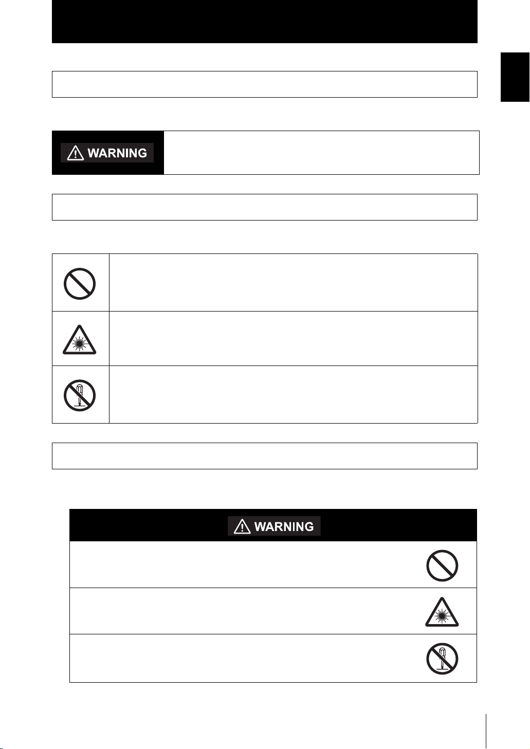
Indicates general prohibitions for which there is no specific symbol.
Introduction
Meanings of Signal Words
Introduction
Indicates the possibility of laser radiation.
Indicates prohibition when there is a risk of minor injury from electrical shock
or other source if the product is disassembled.
Alert statements in this Manual
The following alert statements apply to the products in this manual. Each alert statement also
appears at the locations needed in this manual to attract your attention.
This product is not designed or rated for ensuring safety of persons.
Do not use it for such purposes.
Never look into the laser beam. Doing so continuously will result in visual
impairment.
Do not disassemble the product. Doing so may cause the laser beam to
leak, resulting in the danger of visual impairment.
ZS-HL
User’s Manual
5

Introduction
Introduction
Precautions for Safe Use
Precautions for Safe Use
Please observe the following precautions for safe use of the products.
(1) Installation Environment
• Do not use the product in environments where it can be exposed to inflammable/
explosive gas.
• To secure the safety of operation and maintenance, do not install the product close to
high-voltage devices and power devices.
(2) Power Supply and Wiring
• The supply voltage must be within the rated range (DC24 V ± 10 %).
• Reverse connection of the power supply is not allowed.
• Open-collector outputs should not be short-circuited.
• Use the power supply within the rated load.
• High-voltage lines and power lines must be wired separately from this product. Wiring
them together or placing them in the same duct may cause induction, resulting in malfunction or damage.
(3) Others
• Do not attempt to dismantle, repair, or modify the product.
• Dispose of this product as industrial waste.
6
ZS-HL
User’s Manual

Introduction
Precautions for Correct Use
Precautions for Correct Use
Please observe the following precautions to prevent failure to operate, malfunctions, or
undesirable effects on product performance.
(1) Installation Site
Do not install the product in locations subjected to the following conditions:
• Ambient temperature outside the rating
• Rapid temperature fluctuations (causing condensation)
• Relative humidity outside the range of 35 to 85 %
• Presence of corrosive or flammable gases
• Presence of dust, salt, or iron particles
• Direct vibration or shock
• Reflection of intense light (such as other laser beams or electric arc-welding
machines)
• Direct sunlight or near heaters
• Water, oil, or chemical fumes or spray
• Strong magnetic or electric field
Introduction
(2) Power Supply and Wiring
• When using a commercially available switching regulator, make sure that the FG terminal is grounded.
• If surge currents are present in the power lines, connect surge absorbers that suit the
operating environment.
• Before turning ON the power after the product is connected, make sure that the power
supply voltage is correct, there are no incorrect connections (e.g. load short-circuit)
and the load current is appropriate. Incorrect wiring may result in breakdown of the
product.
• Before connecting/disconnecting the Sensor Head, make sure that the Smart Sensor
is turned OFF. The Smart Sensor may break down if the Sensor Head is connected or
disconnected while the power is ON.
• Use the Extension Cable (provided) for extending the cable between the Sensor Head
and Sensor Controller. The total length varies according to the type of Extension Cable.
- Extension Cable: ZS-XC_A: within 10 m (including Sensor Head cable. Extension
Cable cannot be daisy-chained.)
- Extension Cable: ZS-XC_B(R): within 22 m (including Sensor Head. Up to two
Extension Cables can be daisy-chained.)
- Extension cable for a long distance ZS-XC_ _CR: within 27 m (including Sensor
Head. Digital equalizer ZS-XEQ and the Digital equalizer connection cable ZSXC02D are necessary. The extension cable cannot be daisy-chained.)
• The cable may break at locations when it is made to bend. So, use the robot cable
type Extension Cable (ZS-XC5BR, ZS-XC_ _CR).
• Use only combinations of Sensor Heads and Sensor Controllers specified in this manual.
ZS-HL
User’s Manual
7
Introduction
Introduction
Precautions for Correct Use
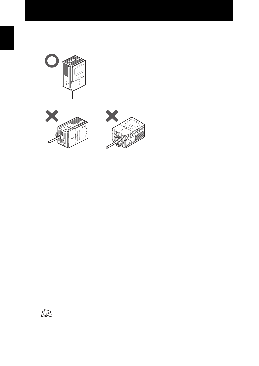
(3) Orientation when Installing the Sensor Controller
To improve heat radiation, install the Sensor Controller only in
the orientation shown below.
Do not install the Sensor Controller in the following orientations.
(4) Warming Up
After turning ON the power supply, allow the product to stand for at least 30 minutes
before use. The circuits are still unstable immediately after the power supply is turned
ON, so measured values may fluctuate gradually.
(5) Maintenance and Inspection
Do not use thinner, benzene, acetone or kerosene to clean the Sensor Head and Sensor Controller. If large dust particles adhere to the front filter of the Sensor Head, use a
blower brush (used to clean camera lenses) to blow them off. Do not blow the dust particles with your mouth. To remove smaller dust particles, wipe gently with a soft cloth
(for cleaning lenses) moistened with a small amount of alcohol. Do not use excessive
force to wipe off dust particles. Scratches on the filter may cause errors.
(6) Sensing Objects
The product sometimes cannot accurately measure the following types of objects:
Transparent objects, objects with an extremely low reflection factor, objects smaller
than the spot diameter, objects with a large curvature, excessively inclined objects, etc.
(7) Effect caused by peripheral lights
Do not install the Sensor Head in a place where strong light hits the laser emitter/
receiver section of the Sensor Head. Also, if a workpiece has a shiny surface, the light
from the lighting will be reflected and a malfunction may occur. In such a case, prevent
reflection by, for example, covering the light to stop reflection.
p.2-4
8
ZS-HL
User’s Manual
Editor's Note
Page Format
Introduction
Precautions for Correct Use
Introduction
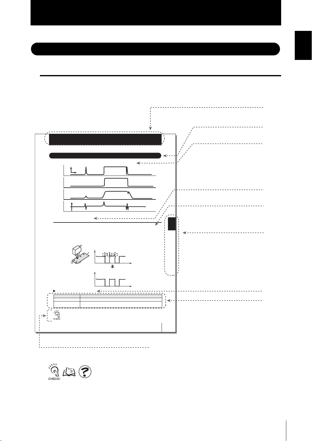
Title of each section
Header
Setting the Filter Function
Section5
Setting the Filter Function
Set the conditions for filtering information obtained from the sensor.
Wavefor m
when filter
function is not
set
SMOOTH
Average
value
Differentiation
Displacement
Smooth
Spike-like changes are
removed.
Changes are smoothed out.
Displacement
0
Changes are extracted to
eliminate displacement value.
Setting SMOOTH
The intermediate value of multiple sets of data can be output as the measurement result.
This function removes any abnormal values such as spiking that occur when the shape of
the workpiece suddenly changes during measurement.
Example: To remove spiking
FUN Mode-[FILTER]-[SMOOTH]
Setting Description
OFF The smooth function is not used.
ON The intermediate value of the past 15 measured values is set as the measurement
When "HI-SPEED" is set in the measurement mode, [OFF] is set.
Abnormal values such as spiking that occur when the shape
of the workpiece suddenly changes during measurement.
Measured valueMeasured value
The smoothing function can remove spikes
result at each sampling cycle.(default value)
Time
Time
Overview
Cross-header
Overview of the
cross-header
Section5 SETTINGS FOR FUNCTIONS
Index label
Indicates the section
number and title.
Movement through menus
up to setting items
Explanation of options
User’s Manual
Supplementary Explanation
Helpful information regarding operation and reference
pages are introduced here using symbols.
*This page has been made purely for explanatory purposes and does not exist.
ZS-HL
5-11
ZS-HL
User’s Manual
9
Introduction
Introduction
Precautions for Correct Use
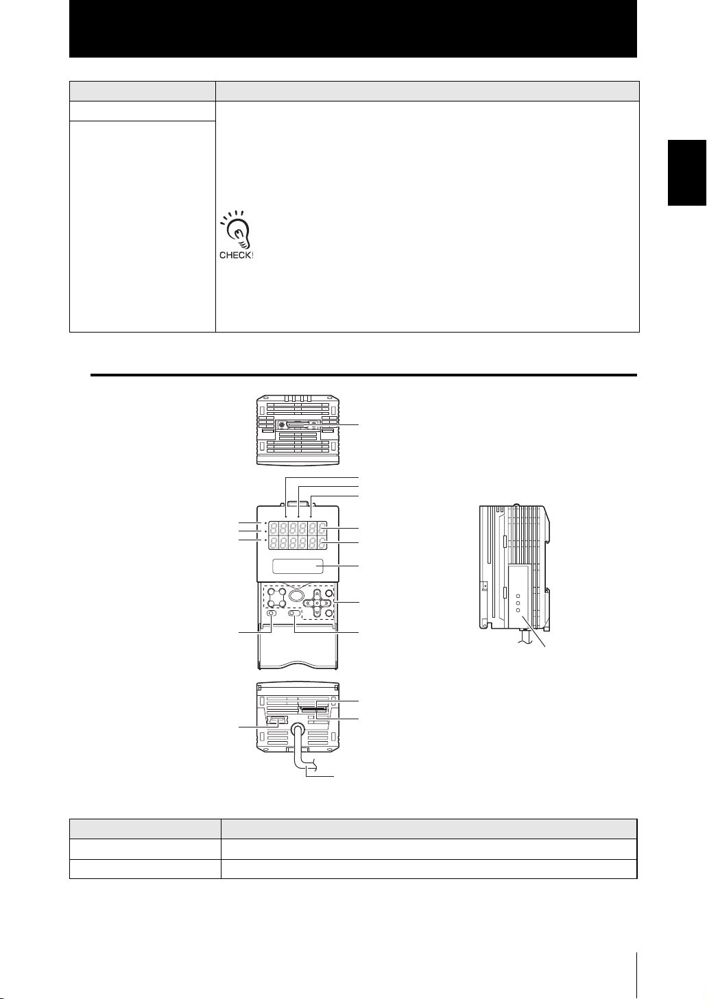
■ Meaning of Symbols
Menu items that are displayed on the Sensor Controller’s LCD screen, and windows,
dialog boxes and other GUI elements displayed on the PC are indicated enclosed by
brackets [aa].
■ Visual Aids
Indicates points that are important to ensure full product performance, such as operational
precautions and application procedures.
Indicates pages where related information can be found.
Indicates information helpful in operation.
10
ZS-HL
User’s Manual

Introduction
CONTENTS
Meanings of Signal Words 5
Meanings of Alert Symbols 5
Alert statements in this Manual 5
Precautions for Safe Use 6
Precautions for Correct Use 7
Editor's Note 9
Page Format 9
CONTENTS 11
Search from Menu Tree 16
Section 1 FEATURES 1-1
Introduction of the ZS-HL Series 1-2
CONTENTS
Section 1 Section 2 Section 3 Section 4 Section 5 Section 6 Section 7 Section 8 Section 9
System Configuration 1-3
Part Names and Functions 1-4
Sensor Head 1-4
Sensor Controller 1-5
Operation Modes 1-7
Setting Flow 1-8
Section 2 INSTALLATION & CONNECTION 2-1
About Installation and Connection 2-2
Sensor Head 2-2
Measuring Range 2-3
Basic Precautions for Installation 2-4
Connecting the Sensor Head 2-5
Sensor Controller 2-7
Installation of Sensor Controller 2-7
Wiring the I/O cable 2-10
I/O Circuit Diagrams 2-12
SmartMonitor ZS 2-14
Operating Environment 2-14
Installation/Uninstallation Method 2-15
ZS-HL
User’s Manual
11

Introduction
CONTENTS
Section 3 APPLICATION and SETTING EXAMPLES 3-1
Section 4 FUNCTIONS AND OPERATIONS USED DURING OPERATION 4-1
Starting and Exiting SmartMonitor ZS 2-19
Measuring Height (basic) 3-2
Measuring the Thickness of Transparent Objects 3-4
Measuring the Vertex 2 (peak) in the Line Beam 3-6
Measuring Multiple Items Simultaneously (Multi-Task) 3-8
Switching the Display of the Measured Value 4-2
List of Key Operations in RUN Mode 4-4
Zero Reset Operation 4-5
Threshold Setting 4-7
Bank Switching (change of device setup) 4-10
Section 5 SETTINGS FOR FUNCTIONS 5-1
Basic Operations of Sensor Controller 5-2
Displays and Key Operations 5-2
Using the Multi-Task Function 5-4
Switching to Multi-Task Mode 5-5
Selecting Tasks 5-5
Setting for Sensing Conditions 5-6
Setting Measurement Mode 5-6
Setting GAIN 5-7
Setting Head Installation 5-8
Setting the Emitted Light Amount 5-8
Setting Measurement Object 5-9
Setting Mutual Interference Prevention 5-11
Setting the Filter Function 5-12
Setting SMOOTH 5-12
Setting AVERAGE 5-13
12
Setting Differentiation 5-13
Setting Output Processing of Sensing Information 5-14
Setting the Scaling 5-14
Setting HOLD Functions 5-18
ZS-HL
User’s Manual

Introduction
Setting the Zero Reset Function 5-22
Setting for Measurement of Characteristic Points 5-24
CONTENTS
Setting Display Method 5-25
Setting the Digital Display 5-25
Displaying HELP 5-25
Setting the LCD Screen 5-26
Setting the System Environment 5-27
Checking Information 5-27
Setting the Key Lock 5-27
Setting the Sensor Load Method 5-28
Setting the Display Language 5-28
Changing the Way of Obtaining Banks 5-28
Saving the Settings Data 5-29
Clearing the Settings 5-29
Initializing All Settings 5-29
Clearing Banks 5-29
Section 6 I/O 6-1
Overview 6-2
Section 1 Section 2 Section 3 Section 4 Section 5 Section 6 Section 7 Section 8 Section 9
I/O Cable 6-2
Terminal Block Output 6-2
Settings for Linear Output 6-3
Assignment of Linear Output 6-3
Setting Focus 6-4
Correcting Linear Output Values 6-5
Settings for Judgment Output 6-7
Operation Settings at Judgment Output 6-7
Assignment of Judgment Output (For Multi-Task) 6-8
Settings for Terminal Block Output 6-9
Real-Time Parallel Output Unit 6-9
Assignment of Terminal Block Output 6-10
Output Format 6-11
Setting Focus 6-13
Setting the Update Cycle 6-14
ZS-HL
User’s Manual
13

Introduction
CONTENTS
Section 7 USB/RS-232C COMMUNICATION 7-1
Settings for Processing when Measurement Cannot be Performed 6-15
When Connecting ZS-MDC and ZS-DSU 6-16
Settings for Input Signal 6-17
Settings for the Active Direction of an Input Signal 6-17
Changing the Assignment of Input Signals 6-17
Timing Charts 6-18
Overview 7-2
USB 7-2
RS-232C 7-3
Connecting Using a USB Cable 7-4
Connection Method 7-4
Setting the Communication Specifications 7-4
Connecting Using a RS-232C Cable 7-5
Connection Method 7-5
Setting the Communication Specifications 7-6
Settings for High-Speed Digital Output 7-7
Timing Charts 7-8
Section 8 SPECIFICATIONS AND EXTERNAL DIMENSIONS 8-1
Sensor Head 8-2
Specifications 8-2
External Dimensions 8-7
Adjusting Mutual Interference 8-15
Spot Diameter 8-19
Usage Width of Line Beam 8-20
Linearity Characteristic by Materials 8-21
Sensor Controller 8-38
Specifications 8-38
External Dimensions 8-40
14
Accessory 8-41
Panel Mount Adapter 8-41
Extension Cable 8-42
ZS-HL
User’s Manual

Introduction
Extension Cable (Long-Distance, Flexible Type) 8-43
RS-232C Cable 8-45
Control Link Unit 8-46
Real-Time Parallel Output Unit 8-47
Section 9 APPENDIX 9-1
Troubleshooting 9-2
Error Messages and Countermeasures 9-3
Safety Precautions for Using Laser Equipment 9-4
Requirements from Regulations and Standards 9-6
Summary of Requirements to Manufactures 9-6
Summary of Requirements to User 9-10
Definitions of Laser Classification 9-13
Updating Firmware 9-15
CONTENTS
Flow of Updating Firmware 9-15
Index 9-21
Revision History 9-25
ZS-HL
User’s Manual
15
Introduction
CONTENTS
CONTENTS
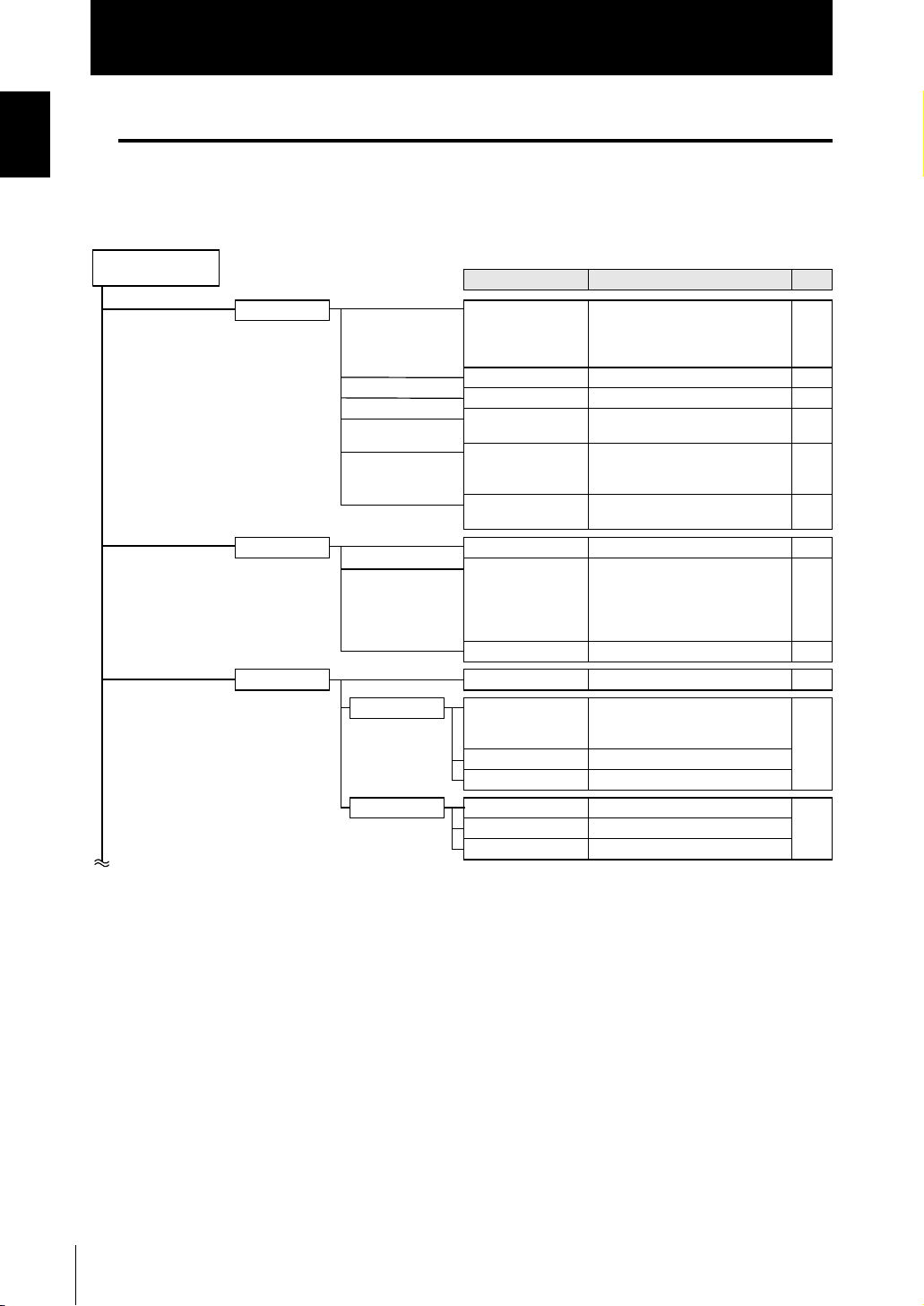
Search from Menu Tree
■ FUN Mode
● For the Single-Task mode
FUN Mode
Settings Option/Range
SENSING MODE
GAIN
SETTING
LASER
OBJECT
SYNC
FILTER SMOOTH
AVERAGE
DIFF
OUTPUT SCALING
HOLD TYPE
TRIGGER
DELAY
Zero reset TYPE
OFFSET
STATUS
*Default Value
Pages
STAND, HI-RESO*, HI-SPEED, HISENS
CUSTOM (EXPOSE, SKIP,
LINE)
1*, 2, 3, 4, 5 p.5-7
DIFFUSE, REGULAR p.5-8
AUTO*, RANGE, FIXED
(upper limit 0.1 to 80 %)
NORMAL*, PCB, MIRROR,
GLASS (MODE 1, MODE2),
THICK (MODE 1, MODE2)
OFF*,
ON (timing A, timing B)
*
OFF, ON
1, 2, 4, 8, 16, 32, 64, 128*, 256, 512,
1024, 2048, 4096
(When the mode is set to HIGHSPEED mode, the value is from 1 to
256.)
OFF*, ON p.5-13
OFF*, ON (AUTO, MAN) p.5-14
OFF*, PEAK, BOTTOM,
P-P, AVERAGE,
SAMPLE
EXT*, SELF-UP, SELF-DN
OFF*, ON
(T-DELAY, T-TIME)
REAL*, HOLD p.5-22
-999.999 to 999.999 (default value:0)
*
OFF, ON
p.5-6
p.5-8
p.5-9
p.5-11
p.5-12
p.5-13
p.5-18
16
ZS-HL
User’s Manual
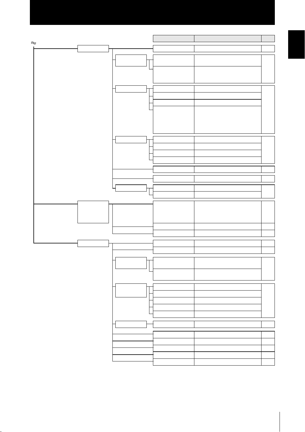
Settings Option/Range
I/O SET NO MEAS
JUDGE
HYS
TIMER
ANALOG FOCUS
ADJUST
OUT
CLAMP
TERMINAL FOCUS
CYCLE
OUT
CLAMP
DIGITAL
CONNECT
INPUT ACTIVE
MODE
CHANGE
BANK
MODE
CLEAR
SYSTEM SAVE
INIT
INFO
CYCLE
VERSION
COM
(RS-232C)
LENGTH
PAR ITY
STOP
BAUDRAT
DELIMIT
COM NODE
KEYLOCK
SenINFO
ZERORST
MUITI
LANGUAG
Introduction
CONTENTS
Pages
KEEP, CLAMP
0 to 999.999 (default value: 0.05 %
of Sensor Head measuring range)
OFF*, OFF-DLY (1 to 5,000 ms),
ON-DLY (1 to 5,000 ms),
1SHOT (1 to 5,000 ms)
OFF*, ON p.6-3
OFF*, ON (-999 to 999)
OFF, ON
(for current output)
4`20 mA (every1 mA), MAX
(for voltage output)
-10 V to 10 V (every1 V), MAX
MIN
OFF*, ON p.6-9
1 to 100 (default value: 1)
NONE*, MEASURE, JUDGE
0 to 65535 (default value: 65535)
OFF, ON
OFF, ON
IN0 to IN3 (OFF, ON
NORMAL*, BANK
BANK1*, BANK2, BANK3, BANK4
(if you change the mode to
[THRESH], you can select up to
BANK32.)
NORMAL*, THRESH p.5-28
(Initializes bank settings.) p.5-29
(Saves Sensor Controller settings.)
(Initializes Sensor Controller settings.)
(Displays the current sampling
cycle.)
(Displays the Sensor Controller version.)
8 BIT*, 7 BIT p.7-6
NONE*, ODD, EVEN
1 BIT*, 2 BIT
9600, 19200, 38400*, 57600, 115200
CR*, LF, CR+LF
0 to 16 (default value: 0) p.7-6
OFF*, ON p.5-27
LOAD*, SAVE p.5-28
OFF*, ON p.5-23
OFF*, ON p.5-5
Japanese*, English p.5-28
*
*
*
*
*)
*
, MIN
p.6-15
p.6-7
*
,
p.7-7
p.6-16
p.6-17
p.4-10
p.5-29
p.5-29
p.5-27
CONTENTS
ZS-HL
User’s Manual
17
Introduction
CONTENTS
CONTENTS
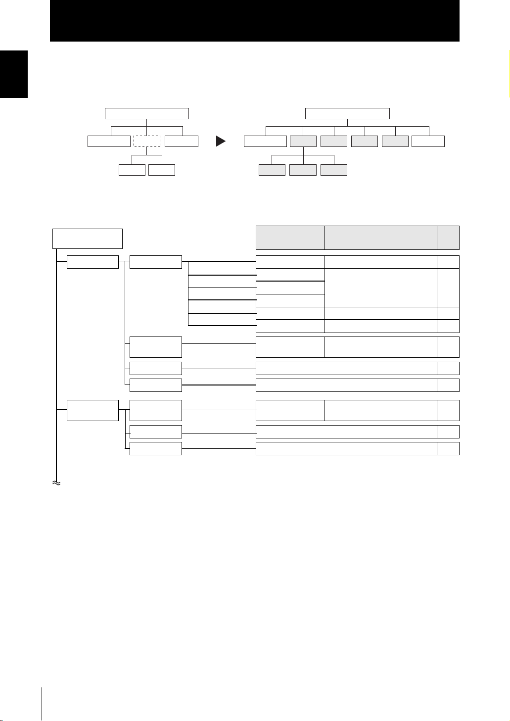
● For Multi-Task mode
The menu configuration is changed to one in which multiple characteristic points can
be measured and output simultaneously (up to four characteristic points).
Single-Task mode
SENSING I/O SETTASK1
FILTER
OUTPUT
SENSING I/O SETTAS K1
MEASURE
FILTER
Multi-Task mode
TAS K2 TA SK3 TA SK4
OUTPUT
This section describes only the parts that are different from those in Single-Task mode.
FUN Mode
TASK1 SENSING MODE
MEASURE
FILTER (Same as Single-Task mode)
OUTPUT (Same as Single-Task mode)
Settings
GAIN
SETTING
LASER
OBJECT
SYNC
TASKSET
(Difference with Single-Task mode)
([HIGH SPEED] is not displayed.) –
(Same as Single-Task mode) –
([THICK] is not displayed.) –
(Same as Single-Task mode) –
NONE*, AVERAGE, PEAK, BOTTOM, THICK, STEP, K+mX+nY
Option/Range
*Default Value
Pages
p.5-24
–
–
18
TASK2 to 4 MEASURE
ZS-HL
User’s Manual
TASKSET
FILTER (Same as Single-Task mode)
OUTPUT (Same as Single-Task mode)
NONE*, AVERAGE, PEAK, BOTTOM, THICK, STEP, K+mX+nY
p.5-24
–
–
Settings
Introduction
CONTENTS
Option/Range
(Difference with Single-Task mode)
CONTENTS
Pages
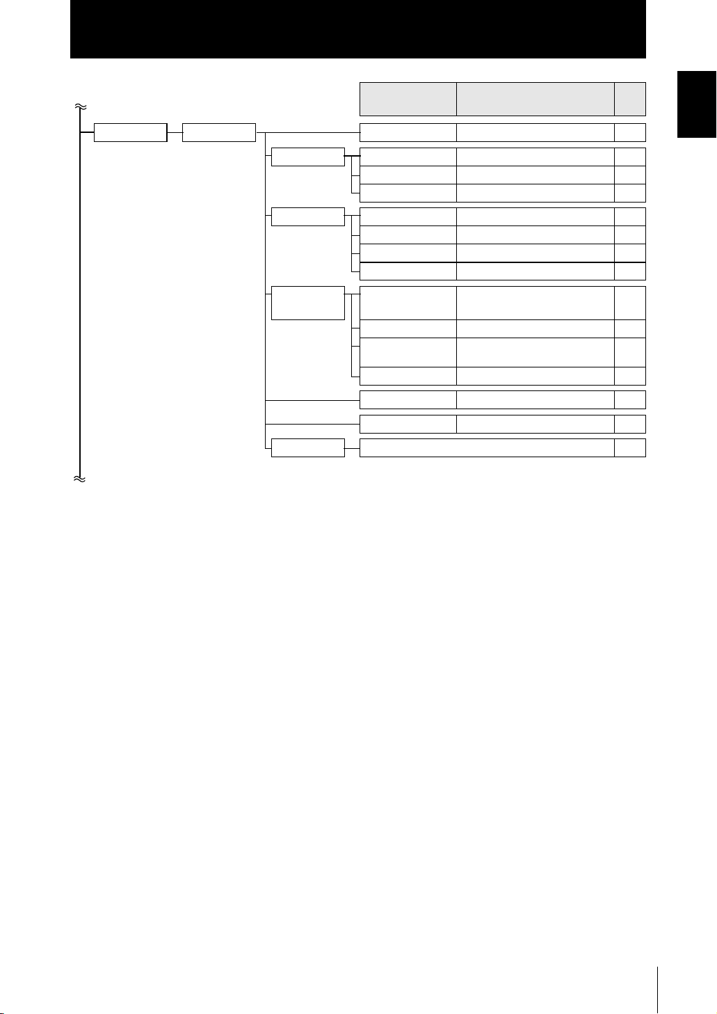
TASK1 I/O SET NON-MEAS
Select TASK you
want to output.
JUDGE HYS
TIMER
OUT
ANALOG FOCUS
ADJUST
OUT
CLAMP LEVEL
TERMINAL
FOCUS
BLOCK
CYCLE
OUT
CLAMP
DIGITAL
CONNECT
INPUT (Same as Single-Task mode)
(Same as Single-Task mode) –
(Same as Single-Task mode) –
(Same as Single-Task mode) –
TASK1*, TASK2, TASK3, TASK4 p.6-8
(Same as Single-Task mode) –
(Same as Single-Task mode) –
TASK1*, TASK2, TASK3, TASK4, None
(Same as Single-Task mode) –
(Same as Single-Task mode) –
(Same as Single-Task mode) –
NONE*, Measured value
TASK4, REPEAT)
(Same as Single-Task mode) –
TASK1 to TASK4 (OFF, ON) p.7-7
TASK1*, TASK2, TASK3, TASK4 p.6-16
(TASK1 to
, JUDGE
p.6-3
p.6-10
–
ZS-HL
User’s Manual
19

Introduction
CONTENTS
CONTENTS
■ RUN mode
In RUN mode, you can customize the details that are displayed in the digital displays.
To call up the display customize menu, press the MENU key in RUN mode.
RUN Mode
DIGITAL
LCD ON/OFF
■ TEACH Mode
This is the mode for setting the threshold values.
TEACH Mode
Settings Option/Range
DOT
ECO
B.LIGHT
CUSTOM
HELP
Settings Option/Range
TEACHING
DIRECT IN
0 to 5th
(Item whose default value varies
according to the connected Sensor
Head)
NORMAL*, ECO, OFF p.5-25
ON*, AUTOOFF, OFF p.5-26
ON*, AUTOOFF, OFF p.5-26
U- ON/OFF, L- ON/OFF
U- CUSTM, L- CUSTM
(default value: U- OFF, L- OFF)
–p.5-25
–p.4-7
–
Pages
p.5-25
p.5-26
Pages
20
ZS-HL
User’s Manual
Section 1 FEATURES
Introduction of the ZS-HL Series 1-2
System Configuration 1-3
Part Names and Functions 1-4
Sensor Head 1-4
Sensor Controller 1-5
Operation Modes 1-7
Setting Flow 1-8
Section 1 FEATURES
ZS-HL
User’s Manual
1-1
Section 1
Introduction of the ZS-HL Series
Introduction of the ZS-HL Series
Section 1 FEATURES
The ZS-HLDC Series is a 2D COMS laser type displacement sensor. In addition to ZS-L
full-digital processing, it maximizes sensing performance using a multi-task function.
Sensor Head
(1)
LD ON ZERO ENABLE
H
SmartMonitor ZS
Personal computer
(3)
P
L
Sensor Controller
(2)
(1) Enhanced Variation of Sensor Heads
Suitable as a high-end displacement sensor, it supports a wide range of Sensor Heads.
You can perform a stable measurement using a Sensor Head that is suitable for the
workpiece, from 0.001 µm ultra-high-resolution type to 1500-mm ultra-long-range type.
(2) Sensor Controller Incorporating Multiple Functions
For one sensing condition, it incorporates a multi-task function that holds up to a
maximum of four kinds of measurement processing as a “task.” Because you can
measure any characteristic point for each task, you can measure and judge multiple
characteristic points simultaneously.
1-2
Example: Measure the height and surface fluctuation simultaneously.
Surface fluctuation (TASK2)
Height (TASK1)
(3) Setting Support Software for Personal Computer “SmartMonitor ZS”
It displays data and specifies the settings for the controller that is connected via
“SmartMonitor ZS” bundled with the Sensor Controller (ZS-HLDC_1A). You can
easily check the sensing status and specify the settings in more detail, which cannot
be done using a controller.
If you use “SmartMonitor ZS Professional,” which is sold separately, you can do logging for a
measured value.
ZS-HL
User’s Manual
System Configuration
RUN
Section 1
System Configuration
In addition to operations with the basic configuration, ZS-HLDC can support various
measurement applications when combined with numerous peripheral devices.
Basic configuration
Sensor Head
ZS-HLDS_ _ _/LD_ _
Detects a sensing object.
LD ON ZEROENABLE
H
P
L
(*1)
SmartMonitor ZS
(Setting support software for personal computers)
This setting support software sets
sensing conditions while monitoring
the receiving status, and allows a user
to check the measured value in a time
series graph.
*1: Accessory for the Sensor Controller ZS-HLDC_1A
Power supply
DC24 V (±10 %)
Recommended part
(1) If the number of connections is
1: S82K-01524 (DC24 V, 0.6 A)
(2) If the number of connections is
2 to 3: S82K-05024 (DC24 V, 2.1 A)
(3) If the number of connections is
4 to 10: Prepare as many of the
above power supplies of (1) and
(2) as you need.
Sensor Controller
ZS-HLDC_ _
Performs measurements
and outputs the results.
(*1)
USB
USB
RS-232C
ZS-XPT2
RS-232C
ZS-XPT2
Linear output
High-speed parallel
output
DATA
ZS-RPD
RS-232C
PARALLEL OUTPUT UNIT
Real-time parallel
Output unit
ZS-RPD_1
Extension cable for Sensor Head
ZS-XC_A (1 m, 4 m, 8 m)
ZS-XC_ _B(5 m, 10 m): Up to two cables can be connected.
ZS-XC5BR (5 m): Up to two cables can be connected.
Robot cable type.
Long Extend the cable of Sensor Head
• Extension cable for a long
distance (*2)
ZS-XC_ _CR (15 m, 25 m)
Peripheral devices
Personal computer
• Communication using commands
• Communication using SmartMonitor
ZS Professional
Programmable controller
• Communication using commands
Programmable terminal
RUN
•
C
ommunication using NS SmartMonitor
Digital panel meter
• Compare waveforms and make a judgment
High-speed input board (personal computer)
• Obtain measurement data quickly
• Digital equalizer
connection cable
ZS-XC02D (*2)
Section 1 FEATURES
Method of connecting
a cable
*2:
Only the ZS-HLDS@@@ Sensor Head can be connected to the ZS-XC@@CR,
ZS-XC02D, and ZS-XEQ.
p.2-6
• Digital equalizer ZS-XEQ (*2)
User’s Manual
ZS-HL
1-3
Section 1
Part Names and Functions
Part Names and Functions
Section 1 FEATURES
[ZS-HLDS2T]
(3) Receiver
section
(2) Emitter
[ZS-HLDS60/HLDS150]
(3) Receiver
(2) Emitter
The following describes the names and functions of parts of the Sensor Head and Sensor
Controller.
Sensor Head
[ZS-HLDS5T/HLDS10]
(6) NEAR
indicator
(5) FAR
indicator
(5) FAR
indicator
(6) NEAR
indicator
section
section
section
(6) NEAR indicator
(5) FAR indicator
(4) Connector
[ZS-LD10GT/LD15GT]
(2) Emitter section
(3) Receiver section
(4) Connector
(2) Emitter section
(4) Connector
(6) NEAR indicator
(5) FAR indicator
(3) Receiver section
(4) Connector
(5) FAR indicator
(6) NEAR indicator
[ZS-LD_ _ _]
(1) Laser emitter/
receiver section
(4) Connector
1-4
Names Functions
(1) Laser Emitter/Receiver
Section
(2) Emitter section
(3) Receiver section
(4) Connector To be connected to the Sensor Controller
ZS-HL
User’s Manual
This is the section that emits the laser beam and receives reflected light.
Section 1
Part Names and Functions
Names Functions
(5) FAR Indicator These indicators light up as follows according to the distance between the front of the
(6) NEAR Indicator
Sensor Head and the workpiece.
Both NEAR/FAR indicators are lit up: Measuring center distance ± (measuring range
× 10 %)
NEAR indicator is lit up: Near side within measuring range
FAR indicator is lit up: Far side within measuring range
Both NEAR and FAR indicators are flashing: Outside measuring range
These indicators also double as laser alarm indicators.
- At least one of the indicators will either light up or flash after the Sensor
Head is turned ON.
- Both indicators go out for 15 to 25 seconds after the Sensor Head is turned
ON to indicate that the laser beam is OFF.
- Either of these indicators will light up or flash while the laser beam is being
emitted.
- Both indicators go off when the laser beam is OFF.
Sensor Controller
(13) Sensor Head connector
Section 1 FEATURES
(1) Laser indicator
(2) Zero Reset indicator
(3) ENABLE indicator
(12) HIGH indicator
(11) PASS indicator
(10) LOW indicator
H
P
L
LD ON ZERO ENABLE
(4) Main display
(5) Sub-display
(6) LCD screen
(7) Control keys
(9) Threshold switch
(8) Mode switch
(14) Coupler
(15) RS-232C connector
(18) USB port
(16) Voltage/Current switch
(17) I/O cable
Names Functions
(1) Laser indicator The Laser indicator is lit while the Sensor Head is emitting a laser beam.
(2) Zero Reset indicator The Zero Reset indicator is lit while the zero reset function is enabled.
ZS-HL
User’s Manual
1-5
Section 1
Part Names and Functions
(3) ENABLE indicator The ENABLE indicator lights when the Sensor is ready for measurement.
Section 1 FEATURES
(4) Main Display The Main Display shows measured values.
(5) Sub-display The sub-display shows thresholds and additional information during measurement.
(6) LCD screen RUN mode : Displays additional information for the main display and the setup
(7) Control keys The Control Keys are for setting measurement conditions and other information. The
(8) Mode switch The Mode Switch selects the operating mode.
(9) Threshold switch The Threshold Selector switch selects whether to set (or display) the HIGH or LOW
(10) LOW indicator The LOW indicator is lit while the condition “measured value < LOW threshold” is
(11) PASS indicator The PASS indicator is lit while the condition “LOW threshold ≤ measured value ≤
(12) HIGH indicator The HIGH indicator is lit while the condition “HIGH threshold < measured value” is
(13) Sensor Head connec-
(14) Coupler This connector is used to connect two or more Sensor Controllers. It is located on
(15) RS-232C connector Connect the RS-232C cable when you are connecting the Sensor Controller to a
(16) Voltage/Current switch The Voltage/Current switch selects between voltage output and current output.
Names Functions
It goes off when measurement is not possible (e.g. when the received light amount is
excessive or insufficient, when the measuring range is exceeded, when the Sensor
Head is not connected, or when measurement is not being performed in FUN mode).
menu for display related information.
TEACH mode: Displays the menu for setting up the thresholds.
FUN mode : Displays the measurement condition setup menu.
functions assigned to the Control Keys change according to the operating mode.
Key Operations p.4-4, p.5-2
RUN mode : Select this mode when performing regular measurement.
TEACH mode: Select this mode when setting the judgment thresholds.
FUN mode : Select this mode when setting measurement conditions.
threshold.
satisfied.
HIGH threshold” is satisfied.
satisfied.
This connector connects the Sensor Head.
tor
both sides of the Sensor Controller.
PLC or a programmable terminal. For the RS-232C cable, please use the following
exclusive products: If you use a cable not included in the exclusive products, a malfunction or breakdown may result.
- For connecting to a PLC or programmable terminal: ZS-XPT2
- For connecting to a personal computer: ZS-XRS2
If you connect the Sensor Controller to ZS-RPD and use it, connect a connector for
ZS-RPD.
1-6
Before operating this switch, make sure that the Sensor Controller is turned
OFF. Also, make sure that the load connected to “linear output wire (coaxial) - linear GND wire” satisfies the rating of the set state (voltage or current output) before turning the Sensor Controller ON. Otherwise, the Sensor
Controller may be damaged.
Rating of connected load (I/O Circuit Diagrams) p.2-12
(17) I/O Cable The I/O cable connects the Data Storage Unit to the power supply and external
devices, such as timing sensors or programmable controllers.
(18) USB port Connect the USB cable to the USB port to connect to a personal computer.
ZS-HL
User’s Manual
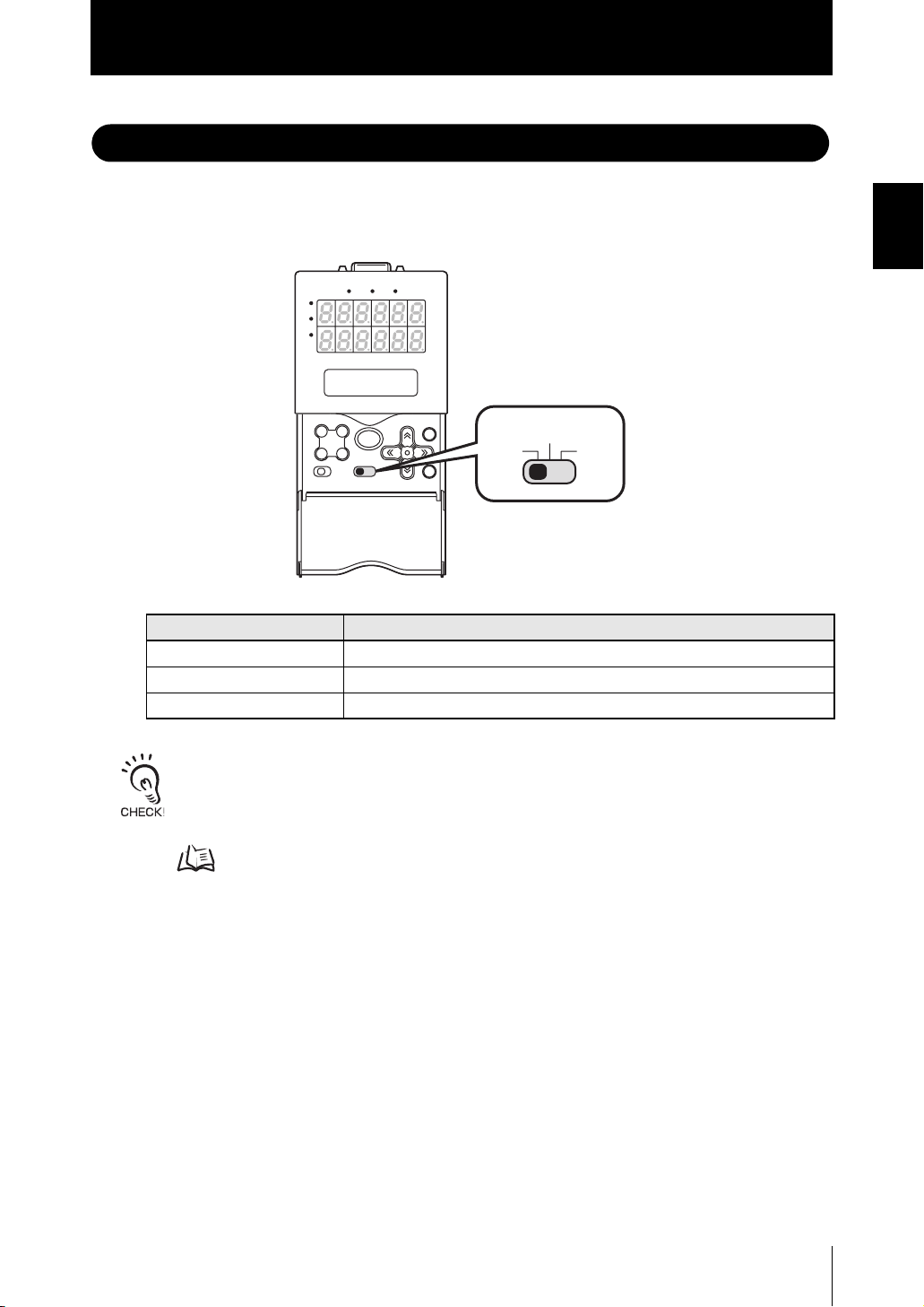
Operation Modes
Section 1
Operation Modes
The ZS-HL has the following 3 operating modes. Switch to the desired mode before you
start operation.
To switch the operating mode, use the mode switch.
LD ON ZERO ENABLE
H
P
L
TEACH
RUNFUN
Mode Description
RUN Mode Normal operating mode
TEACH Mode This mode is for setting the judgment threshold values.
FUN Mode Mode for setting the measurement conditions.
Section 1 FEATURES
When you switch the operating mode after changing the measurement conditions, you will be prompted
to save the settings. Save the settings as required. If you turn off the Sensor Controller without saving
these settings, the newly set measurement conditions will be cleared from memory. You can also save
all the settings later on.
Saving the Settings Data p.5-29
ZS-HL
User’s Manual
1-7
Section 1
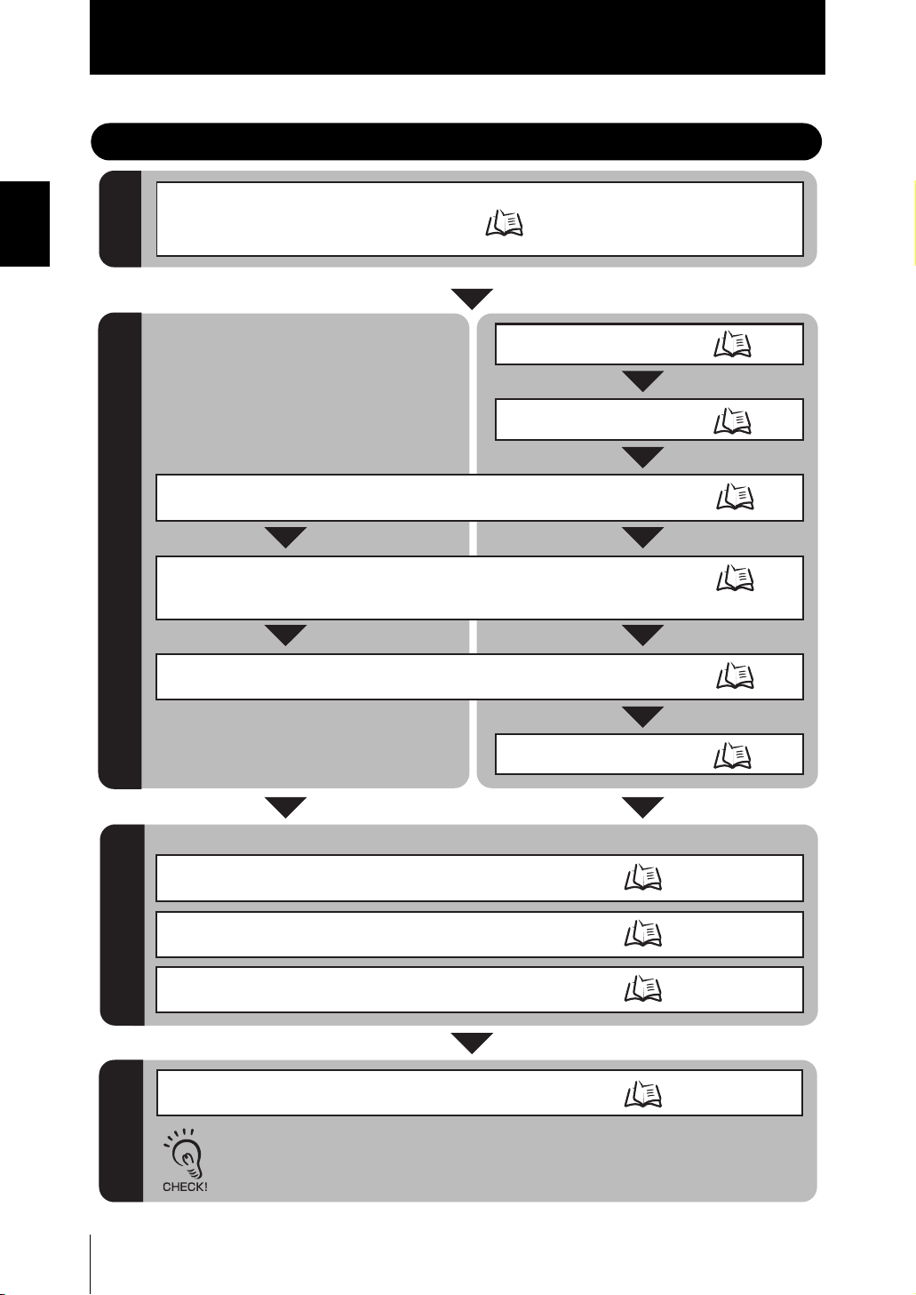
Setting Flow
Section 1 FEATURES
Setting Flow
Installation & Connection
Attach a Sensor Head according to the front side
Preparation for
material of the workpiece and the features of the Sensor.
measurement
Single-Task Multi-Task
Turn ON the power.
Section2
INSTALLATION & CONNECTION
p.2-2
Switching to Multi-Task Mode
Selecting Tasks
Selecting the Status of Head Installation
Select either regular reflection or diffuse reflection.
Selecting Measurement Mode
Change it when the received light amount is small or when you want to increase the
processing speed. (Usually, select [HI-RESO] of the default values.)
Setting for measurement conditions
Selecting the Measurement Object
Change it when you measure glass or mirrors. (Usually, select [NORMAL] of the default values.)
Setting for Measurement
of Characteristic Points
When you select Multi-Task mode, specify the setting for each task.
p.5-4
p.5-5
p.5-8
p.5-6
p.5-9
p.5-24
1-8
Setting the Scaling
You can correct the display value of the measured value as desired.
Setting HOLD
Set the hold conditions.
Setting the Zero Reset Function
Set zero reset.
Setting for output processingSaving the Settings
Save the Settings Data
Save the data you have set.
ZS-HL
User’s Manual
p.5-14
p.5-18
p.5-22
p.5-29
Make sure that you always save the data after you set it.
If you turn OFF the power without saving the data, all the settings data will be cleared.
Section 1
I/O (JUDGE, LINEAR, and OUTPUT
of TERMINAL BLOCK)
Setting Flow
Executing Zero Reset
Threshold Setting
Operation
Bank Switching
Functions Used During
Adjusting and Setting Sensing
Conditions
Setting the Filter Function
Measurement Smoothly
If You Cannot Perform a
I/O (JUDGE, LINEAR, and OUTPUT
of TERMINAL BLOCK)
USB/RS-232C communication
Setting Banks
Setting the Display Method
p.4-6
p.4-7
p.4-10
Setting the Emitted Light Amount
Setting Mutual Interference Prevention
Setting GAIN
Setting SMOOTH
Setting AVERAGE
Setting DIFF
Section6 I/O
Section7
USB/RS-232C COMMUNICATION
Changing the Way of
Obtaining Banks
Clearing Banks
Setting the Display
Setting the LCD display
HELP
Section 1 FEATURES
p.5-8
p.5-11
p.5-7
p.5-12
p.5-13
p.5-13
p.6-2
p.7-2
p.5-28
p.5-29
p.5-25
p.5-26
p.5-25
Setting the System Environment
Operations and Settings as Required
When a Problem Occurs...
When The Smart Sensor Does
Not Operate Correctly
When An Error Message Appears
Initializing Settings Data
Checking Information
Setting the Communication
Specifications
Setting Key Lock
Setting the Sensor Load Method
Setting the Display Language
Troubleshooting
Error Messages and
Countermeasures
p.9-2
p.9-3
p.5-29
p.5-27
p.7-6
p.5-27
p.5-28
p.5-28
ZS-HL
User’s Manual
1-9

Section 1
Setting Flow
Section 1 FEATURES
MEMO
1-10
ZS-HL
User’s Manual

Section2 INSTALLATION & CONNECTION
About Installation and Connection 2-2
Sensor Head 2-2
Measuring Range 2-3
Basic Precautions for Installation 2-4
Connecting the Sensor Head 2-5
Sensor Controller 2-7
Installation of Sensor Controller 2-7
Wiring the I/O cable 2-10
I/O Circuit Diagrams 2-12
SmartMonitor ZS 2-14
Operating Environment 2-14
Installation/Uninstallation Method 2-15
Starting and Exiting SmartMonitor ZS 2-19
Section2 INSTALLATION & CONNECTION
ZS-HL
User’s Manual
2-1
Section2
About Installation and Connection/Sensor Head
About Installation and Connection
■ Checking the installation environment
Section2 INSTALLATION & CONNECTION
■ Checking the installation site
■ About the power supply
Read “Important Points on Safety” at the beginning of this manual, and check the
installation environment.
Read “Notes on Use” at the beginning of this manual, and check the installation site.
Before installing and connecting the Sensor Controller, be sure to turn it OFF.
Also read “Important Points on Safety” and “Notes on Use” at the beginning of this
manual, and check the power supply and wiring.
Sensor Head
Never look into the laser beam. Doing so continuously will result in
visual impairment.
Never look into the laser beam.
Do not disassemble the product. Doing so may cause the laser beam
to leak, resulting in the danger of visual impairment. Do not disassemble the product.
2-2
ZS-HL
User’s Manual

Section2
Sensor Head
Measuring Range
The ZS-HL Series displays - (minus) for the NEAR side and + (plus) for the FAR side with
the measuring center distance set to 0 (zero).
Example: For the Sensor Head ZS-HLDS2T
Section2 INSTALLATION & CONNECTION
Measurement center
distance: 20 mm
Measuring range
NEAR side
Measuring center
FAR side
-1 mm
0 mm
+1 mm
• ZS-HLDS_ _ _ Series
Regular reflection Diffusive reflection
Measuring center
distance
ZS-HLDS2T 20 mm ±1 mm 5.2 mm ±1 mm
ZS-HLDS5T 44 mm ±4 mm 50 mm ±5 mm
ZS-HLDS10 94 mm ±16 mm 100 mm ±20 mm
ZS-HLDS60 – – 600 mm ±350 mm
ZS-HLDS150 – – 1,500 mm ±500 mm
Measuring range
Measuring center
distance
Measuring range
• ZS-LD_ _ _ Series
Regular reflection Diffusive reflection
Measuring center
distance
ZS-LD10GT 10 mm ±0.5 mm – –
ZS-LD15GT 15 mm ±0.75 mm – –
ZS-LD20T/20ST 20 mm ±1 mm 6.3 mm ±1 mm
ZS-LD40T 40 mm ±2.5 mm 30 mm ±2 mm
ZS-LD50/50S 47 mm ±4 mm 50 mm ±5 mm
ZS-LD80 78 mm ±14 mm 80 mm ±15 mm
ZS-LD130 130 mm ±12 mm 130 mm ±15 mm
ZS-LD200 200 mm ±48 mm 200 mm ±50 mm
ZS-LD350 – – 350 mm ±135 mm
Measuring range
Measuring center
distance
Measuring range
ZS-HL
User’s Manual
2-3

Section2
Sensor Head
Basic Precautions for Installation
Color/shiny surface boundary
Wrong Right
Section2 INSTALLATION & CONNECTION
Color/shiny
surface boundary
Measuring in narrow grooves
Emission axis
Wrong Right
Reception axis
Installing near walls
Measurement errors can be reduced by
installing the Sensor Head with the line
formed by the emission and reception axes
parallel to the wall, and painting the wall with
non-reflective black paint.
Wrong Right
Rotating objects
When measuring rotating workpieces, you can
minimize the influence caused by vibration of
the rotating object and positional shifts by
installing the Sensor Head with the line
formed by the emission and reception axes
parallel to the axis of rotation.
Wrong Right
Measuring stepped workpieces
Wrong Right
Effect caused by peripheral lights
Do not install the Sensor Head in a place
where strong light hits the laser
emitter/receiver section of the Sensor Head.
Also, if a workpiece has a shiny surface, the
light from the lighting will be reflected and a
malfunction may occur. In such a case,
prevent reflection by, for example, covering
the light to stop reflection.
Wrong Right
2-4
ZS-HL
User’s Manual

Sensor Head
Connecting the Sensor Head
This connector connects the Sensor Head and controller.
Before connecting/disconnecting the Sensor Head, make sure that the Smart Sensor is turned OFF. The
Sensor Controller may break down if it is connected or disconnected while the power is ON.
■ Connecting the Sensor Head
Insert the Sensor Head connector into the Sensor Controller until it locks in place.
Section2
Section2 INSTALLATION & CONNECTION
LD ON ZEROENABLE
H
P
L
Ferrite core
Insure lock
Ferrite core
Attach the ferrite core (provided with the Sensor Head) to both ends of the Sensor Head cable in
advance.
If the ferrite core comes loose from the cable, fasten the ferrite core in place with the Insure Lock
(supplied).
■ Disconnecting the Sensor Head
Pull out the Sensor Head while pressing in the hooks on both sides of the Sensor Head
connector.
LD ON ZEROENABLE
H
P
L
• Do not touch the terminals inside the connector.
• All settings on the Sensor Controller will be cleared if the Sensor Head is replaced with a different
type.
ZS-HL
User’s Manual
2-5

Section2
Sensor Head
■ Extension Cable
There are three ways to extend a cable.
• Entire length within 12 m
Section2 INSTALLATION & CONNECTION
LD ON ZEROENABLE
H
P
Cable for the Sensor Head
: 0.5 m, 2 m
Extension cable
ZS-XC_A_: 1 m, 4 m, 8 m
L
ZS-XC_B(R): 5 m, 10 m
• Entire length within 22 m (Connect extension cables)
Cable for the Sensor Head
: 0.5 m, 2 m
Extension cable
ZS-XC_B(R): 5 m, 10 m
ZS-XC_B(R): 5 m, 10 m
• Extended for a long distance (Use a repeater)
Digital equalizer
ZS-XEQ
Cable for the Sensor Head
: 0.5 m, 2 m
Extension cable
ZS-XC15CR: 15 m
ZS-XC25CR: 25 m
Digital equalizer
ZS-XEQ
Extension cable
Digital equalizer
connection cable
ZS-XC02D: 0.2 m
LD ON ZEROENABLE
H
P
L
LD ON ZERO ENABLE
H
P
L
2-6
ZS-HL
User’s Manual
• Only the ZS-XC_B(R) cable allows this extended connected. Note, however, that the connection
with the ZS-XC_A cannot be extended.
• The cable may break at locations where it is made to bend. So, use a robot cable type extension
cable (ZS-XC5BR, ZS-XC_ _CR).
• There are restrictions on the Sensor Head that can connect to ZS-XC_ _CR, ZS-XC02D, and ZS-
XEQ. For details, contact your OMRON representative.

Section2
Sensor Controller
Sensor Controller
This section describes installation of the Sensor Controller, and connection of the I/O
cable.
Before connecting/disconnecting peripheral devices, make sure that the Sensor Controller is turned
OFF. The Sensor Controller may break down if it is connected or disconnected while the power is ON.
Installation of Sensor Controller
■ Installing on the DIN track
The following describes how to attach the 35 mm wide DIN track very quickly and easily.
LD ON ZERO ENABLE
H
P
L
DIN track (sold separately)
PFP-100N (1 m)
PFP-50N (0.5 m)
PFP-100N2 (1 m)
Ferrite core
End plate (sold separately)
PFP-M
Section2 INSTALLATION & CONNECTION
In advance, attach the ferrite core (provided with the Sensor Controller) to the input/output cable of
the Sensor Controller.
ZS-HL
User’s Manual
2-7

Section2
Sensor Controller
● Installation procedure
1. Hook the connector end of the Sensor
Controller onto the DIN track.
Hook on connector
Section2 INSTALLATION & CONNECTION
● Removal procedure
2. Push the Sensor Controller down onto
the DIN track until the hook on the I/O
cable side is locked.
Push down until you hear it snap into place.
Always hook the connector end of the Sensor Controller on the DIN track first. Hooking the I/
O cable end on the DIN track first may impair the mounting strength of the DIN track attach-
ment.
1. Pull the hook on the I/O cable end of the
Sensor Controller downwards.
2. Lift up the Sensor Controller from the I/O
cable end, and remove it from the DIN
track.
Hook on I/O cable
Hook on I/O cable
2-8
■ Mounting on a panel
The optional Panel Mount Adapters (ZS-XPM1) can be used to mount the Sensor Controller on a panel.
Panel cutout dimensions p.8-41
1. Push out the Sensor Controller from the
rear of the panel towards the front.
H
H
LD ON ZERO
LD ON ZERO
P
P
ENABLE
ENABLE
L
L
ZS-HL
User’s Manual
Panel

Section2
Sensor Controller
2. Install the small Mount Adapters on the
four holes of the Sensor Controller.
3. Install the long Mount Adapters on the
two holes of the small Mount Adapter.
Panel Mount
Adapter
H
H
LD ON ZERO
LD ON ZERO
P
P
ENABLE
ENABLE
L
L
Panel Mount
Adapter
H
H
LD ON ZERO
LD ON ZERO
P
P
ENABLE
ENABLE
L
L
Section2 INSTALLATION & CONNECTION
Panel Mount
Adapter
4. Install the Sensor Controller with Panel
Mount Adapters attached onto the panel
from the front.
Take care not to pinch the I/O cable.
5. Hook the hooks of the mounting fixture
onto the two holes of the smaller Mount
Adapters and tighten the screws.
Panel Mount
Adapter
Panel
H
H
L
L
D
D
O
O
N
N
Z
Z
E
E
P
P
R
R
O
O
E
E
N
N
A
A
B
B
L
L
L
L
E
E
Mounting
fixture
6. Make sure that the Sensor Controller is
firmly fixed on the panel.
ZS-HL
User’s Manual
2-9

Section2
Sensor Controller
Wiring the I/O cable
The following shows the leads that comprise the I/O cable.
Section2 INSTALLATION & CONNECTION
(1) Power supply
Brown
Blue
Red
Green
Black
Pink
Gray
Co-axial (black)
Shielded
Yellow
Light blue
Purple
White
Orange
(Cable length: 2 m)
(1) Power supply
(2) GND
(3) OUT0
(4) OUT1
(5) OUT2
(6) OUT3
(7) OUT4
(8) Linear output
(9) Linear GND
(10) IN0
(11) IN1
(12) IN2
(13) IN3
(14) Unused
This connects the 24 VDC (±10 %) power supply. When using a Sensor Controller
with a PNP output, the power supply terminal is also the common I/O terminal for all I/
O except for the linear output.
Supply power from a DC power supply unit that has a countermeasure (safety ultra-
low voltage circuit) built-in for preventing high voltages from occurring.
Recommended power supply unit p.1-3
Wire the power supply separately from other devices. Wiring them together or placing
them in the same duct may cause induction, resulting in malfunction or damage.
(2) GND
The GND terminal is the 0 V power supply terminal. When using a Sensor Controller
with an NPN output, the GND terminal is also the common I/O terminal for all I/O
except for the linear output.
(3) OUT0 (HIGH output)
This outputs judgment results (HIGH).
(4) OUT1 (PASS output)
This outputs judgment results (PASS).
(5) OUT2 (LOW output)
This outputs judgment results (LOW).
(6) OUT3 (ENABLE output)
This turns ON when the Sensor Controller is ready for measurement. This output is
interlocked with the ENABLE indicator.
2-10
ZS-HL
User’s Manual
Sensor Controller
(7) OUT4 (BUSY output)
This turns ON during sampling with the hold function enabled.
It allows you to check whether or not the self-trigger is functioning correctly.
It also turns ON during bank switching.
(8) Linear output
The linear output outputs a current or voltage in accordance with the measured
value.
(9) Linear GND
The linear GND terminal is the 0 V terminal for the linear output.
This ground wire must be grounded separately from the other ground wires.
Always ground the linear output terminal even when linear output is not used.
(10)-(13) IN0 to IN3
The following input signal assignments can be selected.
• Signal assignments
Signal
IN0 External trigger (timing) input Bank input A
IN1 Reset input Bank input B
IN2 LD-OFF input LD-OFF input
IN3 Zero reset input Zero reset input
When [NORMAL] is selected
(default)
When [BANK] is selected
Section2
Section2 INSTALLATION & CONNECTION
Setting the I/O assignments p.6-17
• Signal functions
Signal name Description
External trigger (timing) input This timing input is for signal input from external devices. Use it for hold
function timing.
Reset input This resets all executing measurements and outputs. While a reset is
being input, judgment output conforms to the non-measurement setting. If this reset input switches ON while the hold function is used, the
state in effect before the hold function was set will be restored.
Status indicators p.8-39
LD-OFF input If this LD-OFF signal is set to ON, the laser will stop emission, causing
a light amount error. While LD-OFF is being input, judgment output
conforms to the non-measurement setting.
Zero reset input This is used to execute and clear a zero reset.
Bank input A, B This is used for switching banks. Specify the bank No. in combinations
of A and B. However, if the bank mode is set to [THRESH], the bank
cannot be switched at the external signal input because the number of
banks increases to 32.
External I/O timing chart p.6-18
ZS-HL
User’s Manual
2-11
Section2
Sensor Controller
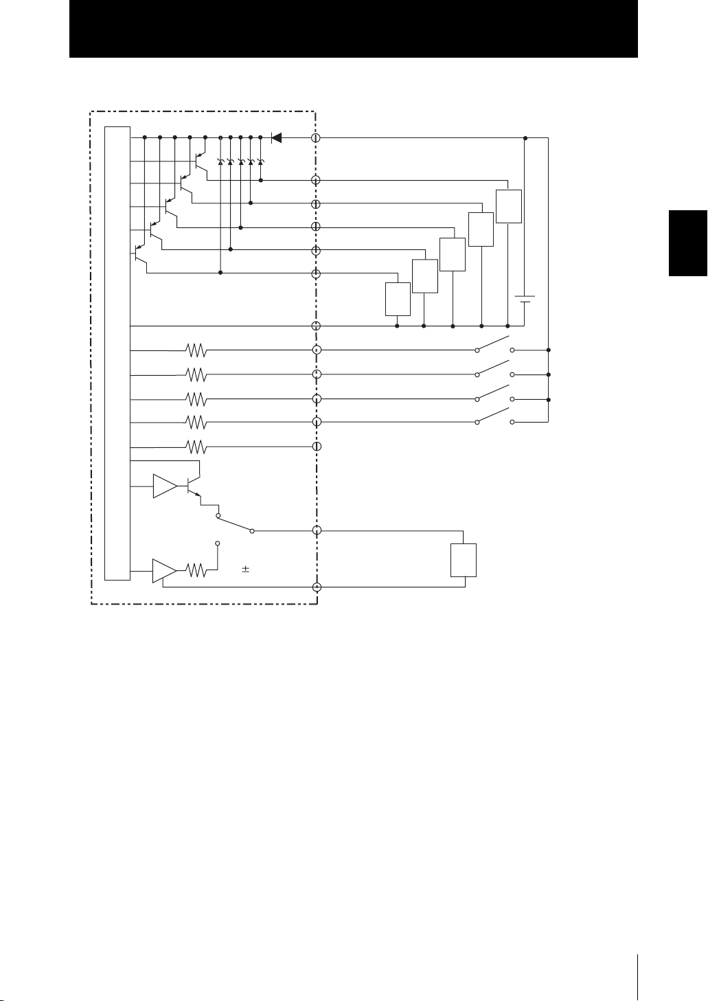
I/O Circuit Diagrams
● NPN type (ZS-HLDC11)
Section2 INSTALLATION & CONNECTION
Brown
Red
Green
Black
Pink
Gray
Blue
DC24 V
Load
OUT0
OUT1
OUT2
OUT3
OUT4
GND (0 V)
Load
Load
Load
Load
DC24 V
Internal circuits
Current voltage/
output selector switch
40 Ω
Current output
4 to 20 mA
Voltage output
10 V
Yellow
Light blue
Purple
White
Orange
Co-axial (black)
Shielded
IN0
IN1
IN2
IN3
Linear output
Linear GND
Current output: 300 Ω or less
Load
Voltage output: 10 kΩ or more
2-12
ZS-HL
User’s Manual
● PNP type (ZS-HLDC41)
Brown DC24 V
Red
OUT0
Green
OUT1
Black
OUT2
Pink
OUT3
Gray
OUT4
GND (0 V)
Blue
Yellow
IN0
Load
Load
Load
Sensor Controller
Load
Load
DC
24 V
Section2
Section2 INSTALLATION & CONNECTION
Internal circuits
Current voltage/
output selector switch
40 Ω
Current output
4 to 20 mA
Voltage output
10 V
Light blue
Purple
White
Orange
Co-axial (black)
Shielded
IN1
IN2
IN3
Linear output
Linear GND
Current output: 300 Ω or less
Load
Voltage output: 10 kΩ or more
ZS-HL
User’s Manual
2-13

Section2
SmartMonitor ZS
SmartMonitor ZS
ZS-HL is provided with the SmartMonitor ZS software utility. This utility allows you to set up
sensing functions and monitor the waveforms of measurement results on a personal computer.
Section2 INSTALLATION & CONNECTION
● Monitoring the measurement state
● Setting support for functions
SmartMonitor ZS
(accessory for ZS-HLDC_1A)
USB cable
Checks the measured value of the gang-mounted
controller in the list.
Sets the sensing conditions in detail while checking
the receiving status of the Sensor Head (sensitivity).
Receiving
status
Displays the change of the time series for the measured value in a graph.
Displays and sets the settings for the controller
in the list.
2-14
Line bright
If you use SmartMonitor ZS Professional, which is sold separately, you can also do the following:
• Display multiple CH waveforms using multiple controllers.
• Perform logging for the measured value.
Operating Environment
The following describes the operating environment for SmartMonitor ZS. Please check them.
Item Condition
OS Windows 98/2000/XP
CPU Celeron 500MHz or faster
Memory At least 128 MB
Display 1024 × 768 dots HighColor
• Windows is a trademark or registered trademark of Microsoft Corporation.
• Celeron is a trademark or registered trademark of Intel Corporation or its subsidiaries.
ZS-HL
User’s Manual

Section2
SmartMonitor ZS
Installation/Uninstallation Method
The following describes the preparations for using SmartMonitor ZS.
■ Installing SmartMonitor ZS
• Before you install SmartMonitor ZS, quit all other programs that are running. If virus detection soft-
ware is enabled, installation may take time to complete.
• Log on as an Administrator or a user with system access rights.
• Install SmartMonitor ZS before installing the USB driver.
1. Turn your PC ON and startup up Windows.
2. Insert your “SmartMonitor ZS” CD-ROM into the CD-DOM drive on your per-
sonal computer.
3. Auto-run automatically displays the installation screen. Follow the on-
screen instructions to install SmartMonitor ZS.
Section2 INSTALLATION & CONNECTION
■ Uninstalling SmartMonitor ZS
• Before you uninstall SmartMonitor ZS, quit all other programs that are running. If virus detection
software is enabled, uninstallation may take time to complete.
• Log on as an Administrator or a user with system access rights.
1. Turn your PC ON and startup up Windows.
2. Select [Settings]-[Control Panel] from the [Start] menu in the personal com-
puter.
3. Double-click [Add/Remove Programs].
4. Select [SmartMonitorZS] from the list and click the [Remove] button.
5. Click the [Yes] button.
ZS-HL
User’s Manual
2-15
Section2
SmartMonitor ZS
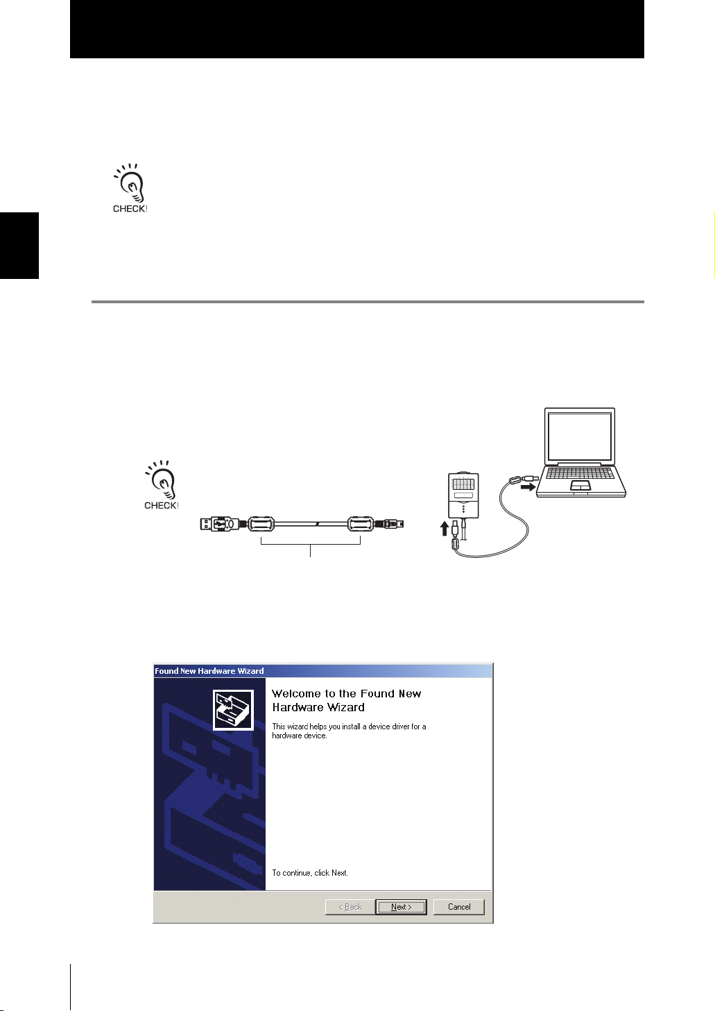
■ Installing the USB driver
Section2 INSTALLATION & CONNECTION
The USB driver must be installed on the personal computer to establish a connection
between the personal computer and the Sensor Controller by the USB interface.
• The exclusive USB driver must be installed only when the Sensor Controller is connected to the
personal computer for the first time. From the second startup onwards, the USB driver is automat-
ically recognized and does not need to be re-installed.
• To install the USB driver, log on as an Administrator or a user with system access rights.
• Install SmartMonitor ZS before installing the USB driver.
• The error message “Failed to pass the Windows logo test” is sometimes displayed at USBinstalla-
tion. Press the [Continue] button to continue with the installation.
1. Turn your PC ON and startup up Windows.
2. Connect the Sensor Controller to the
personal computer by the USB cable.
Attach the ferrite core (provided with the Sen-
sor Controller) to the USB cable (provided with
the Sensor Controller).
Ferrite core
“Detected new hardware” will be displayed on the Windows tool bar,
and the [New Hardware Detection Wizard] dialog box will appear.
2-16
ZS-HL
User’s Manual

Section2
SmartMonitor ZS
3. Click the [Next>] button.
4. Select the [Search for a suitable driver for my disk (recommended)] radio
button, and click the [Next>] button.
Section2 INSTALLATION & CONNECTION
5. Mark the [CD-ROM drives] checkbox, and click the [Next>] button.
• When the Sensor Controller is not detected automatically
Click the [Browse] button and select [USB] folder on the CD-ROM.
• To install on a personal computer not equipped with a CD-ROM driveSelect
[Specify directory], and specify the [Program Files]-[OMRON]-[SmartMonitorZS]-[usb]
folder.
ZS-HL
User’s Manual
2-17

Section2
SmartMonitor ZS
Section2 INSTALLATION & CONNECTION
6. Make sure that the optimum driver has been detected, and click the [Next>]
button.
Installation begins.
When installation ends, the completion message is displayed.
7. Click the [Finish] button.
The same screen in step 2 is displayed. Repeat the above procedure.
This completes installation of the USB driver.
2-18
ZS-HL
User’s Manual

Section2
SmartMonitor ZS
Starting and Exiting SmartMonitor ZS
■ Start-up of SmartMonitor ZS
After installation is completed, start up SmartMonitor ZS by the following procedure.
1. Make sure that the Sensor Controller is connected to the personal com-
puter.
2. Turn the Sensor Controller ON and set it to the RUN mode.
3. Select [Programs]-[OMRON]-[SmartMonitorZS] from the Windows [Start]
menu.
■ When the connection between the personal computer and
Sensor Controller cannot be established
Check the COM port No. assigned on the personal computer in Device Manager.
Section2 INSTALLATION & CONNECTION
1. Right-click [My Computer] on the Windows desktop and click [Properties].
2. Click [Device Manager(D)] on the [Hardware] tab.
3. Open [Port (COM/LPT)], and check which number COM in [OMRON Smart
Sensor USB COM] is set to.
4. Set this COM port No. to the [Communication Settings] screen on Smart-
Monitor ZS.
If “OMRON Smart Sensor USB COM” is not recognized in Device Manager, re-install the USB driver
and reboot the personal computer.
■ Exiting SmartMonitor ZS
Exit SmartMonitor ZS by the following procedure.
1. Select [File]-[Close] in the SmartMonitor ZS menu bar.
ZS-HL
User’s Manual
2-19

Section2
SmartMonitor ZS
MEMO
Section2 INSTALLATION & CONNECTION
2-20
ZS-HL
User’s Manual

Section3
APPLICATION and SETTING EXAMPLES
Measuring Height (basic) 3-2
Measuring the Thickness of Transparent Objects 3-4
Measuring the Vertex 2 (peak) in the Line Beam 3-6
Measuring Multiple Items Simultaneously (Multi-Task) 3-8
Section3 APPLICATION and SETTING EXAMPLES
ZS-HL
User’s Manual
3-1

Section3
t
Measuring Height (basic)
Measuring Height (basic)
This section describes the basic setting procedures for measuring height.
Section3 APPLICATION and SETTING EXAMPLES
Setting for sensing conditions
Sensor head
heigh
Name of the Controller and Key Code
LD ON ZERO ENABLE
Main display
Sub-display
H
P
L
MENU
12
34
H L FUN RUN
TEACH
ESC
SET
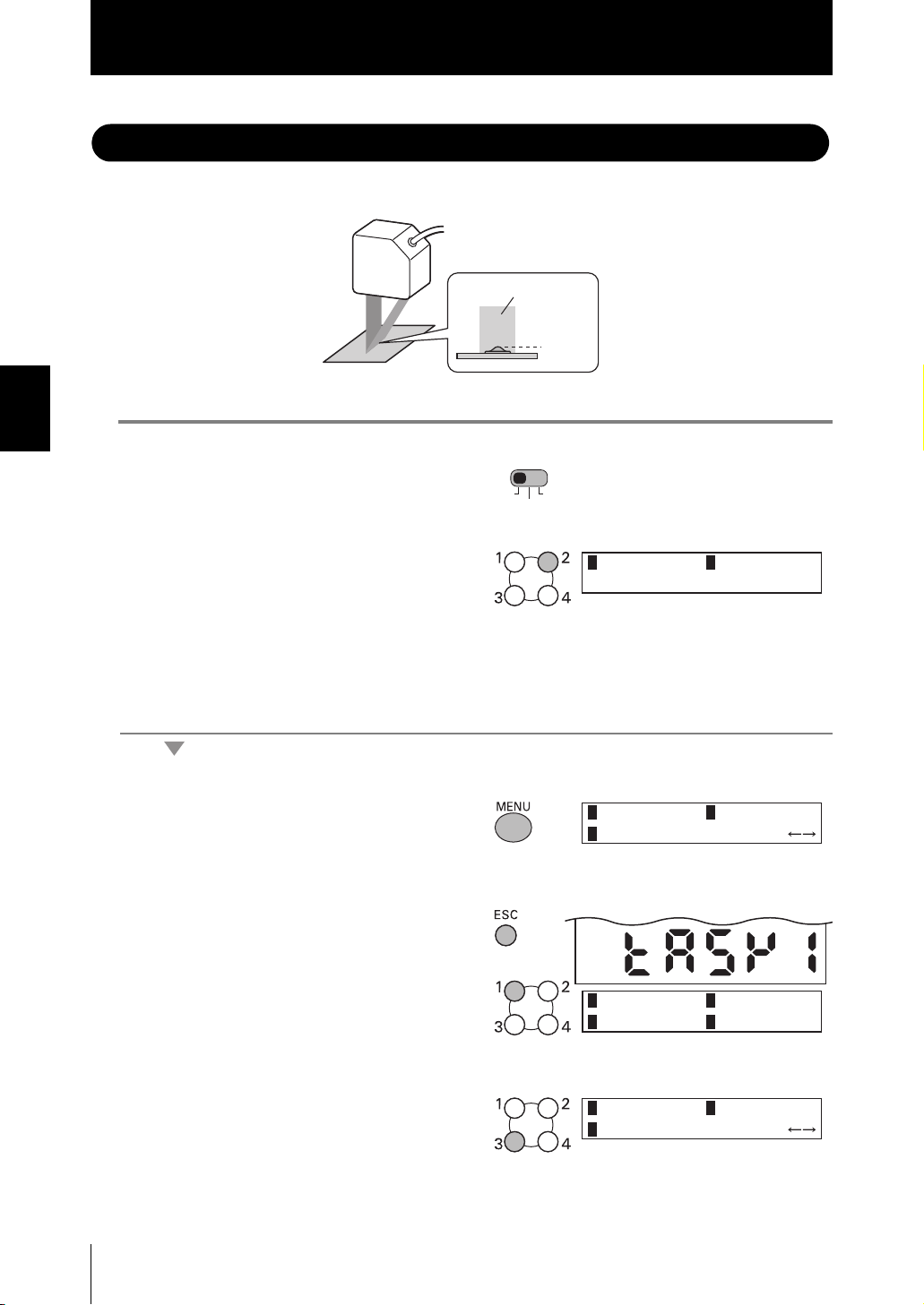
1. Set the mode switch to FUN.
FUN RUN
TEACH
2. Select measurement mode in
[SENSING]-[MODE].
1 STAND
3 H-SPEED
[HI-RESO]:Usually select this menu. A stable measurement can be performed
while the effect of the front side of the workpiece is minimized.
[HI-SENS]: In addition to the effect of [HI-RESO], a measurement is stable even
when the received light amount is insufficient. (black rubber, PCB, etc.)
3. Select the mounting status of the
1 DIFFUSE
Head in [SENSING]-[SETTING].
4. Select the material of the work-
piece in [SENSING]-[OBJECT].
1 NORMAL
3 MIRROR
[NORMAL]: Usually select this menu.
[PCB] : When a laser beam passes through an object like PCB and there is a
diffused reflection effect.
[MIRROR] : For a mirror
[GLASS] : For glass
2 HI-RESO
2 REGULAR
2 PCB
3-2
ZS-HL
User’s Manual

Saving the Settings
5. Set the mode switch to RUN.
FUN RUN
TEACH
Section3
Measuring Height (basic)
6. Select [Yes] and save the settings.
Measurement
7. Check the measured value.
Is change saved?
1 YES 2 NO
Measurement center = 0
Measured
value
Section3 APPLICATION and SETTING EXAMPLES
(-)
(+)
ZS-HL
User’s Manual
3-3

Section3
Measuring the Thickness of Transparent Objects
Measuring the Thickness of Transparent Objects
If you already know the glass thickness, you can adjust the scaling with reference to the
thickness, and easily measure the thickness of a transparent object.
Section3 APPLICATION and SETTING EXAMPLES
Sensor Head
[Points for installation]
•
For regular reflection heads (such as ZS-HLDS2T and ZS-LD20T)
By fixing the Sensor Head to a position such that it is kept in
parallel with the front side of the workpiece, you can perform
high-precision measurement. When you install the Sensor Head,
we recommend that you match the front side of the workpiece
with the reference surface of the Sensor Head, and then bring
up the Sensor Head horizontally and install it.
ront side
Backside
Raw glass
Thickness
Setting for sensing conditions
1. Set the mode switch to FUN.
2. Select [REGULAR] in [SENSING]-
[SETTING].
•
For diffuse reflection heads
Adjust the position of the Sensor Head while checking the
display of the emitted light amount and received light amount.
Adjust the position of the Sensor Head such that the emitted
light amount becomes the minimum compared to 1,000 for the
received light amount.
LD POWER: 1.0%
SUB : BRIGHT
Switching the Display of the Measured Value p.4-2
FUN RUN
TEACH
1 DIFFUSE
Received light amount
Emitted light amount
2 REGULAR
3-4
3. Select [THICK]-[MODE1] in [SENS-
ING]-[OBJECT].
ZS-HL
User’s Manual
1 GLASS
2 THICK

Measuring the Thickness of Transparent Objects
e
Setting Scaling
4. Set the actual workpiece within
the measuring range.
Section3
Measuring distance
Measuring rang
5. Select [OUTPUT]-[SCALING]-[ON]-
[AUTO].
When you want to execute [SCALING FOR GLASS THICKNESS], set the workpiece within
the measuring range. In the status in which a measurement cannot be performed, you cannot
set the scaling (automatic).
6. Enter the actual size of
the glass thickness.
Saving the Settings
7. Set the mode switch to RUN.
Value
Digit
FUN RUN
TEACH
1 AUTO
INPUT THICKNESS
DIG VAL SET:OK
2 MANUAL
Section3 APPLICATION and SETTING EXAMPLES
8. Select [Yes] and save the settings.
Is change saved?
1 YES 2 NO
Measurement
9. Check the measured value.
Measured
value
When a measurement is not stable
Select [THICK]-[MODE2] at the step 3. When you select [MODE2], the mode is switched to 2-area measurement mode that executes an adjustment for suitable received light amount for the front side and
back side of the glass respectively. When you use SmartMonitor ZS, you can adjust the area while
checking the received light amount.
Setting Measurement Object p.5-9
User’s Manual
ZS-HL
3-5
Section3
Measuring the Vertex 2 (peak) in the Line Beam
Measuring the Vertex 2
The following describes the setting procedure for measuring a small vertex.
Section3 APPLICATION and SETTING EXAMPLES
1. Set the mode switch to FUN.
2. Select [ON] in [SYSTEM]-[MULTI-
TASK].
The confirmation message is
displayed. Select [OK].
(peak)
Line beam
Peak
FUN RUN
TEACH
in the Line Beam
1 OFF
2 ON
Setting peak (TASK1)
3. Press the MENU key to display the
TOP menu.
4. Press the ESC key to display the
TASK switching menu, and select
[TASK1].
5. Select [PEAK] in [MEASURE]-
[TASKSET].
1 SENSING
3 FILTER
1 TASK1
3 TASK3 4 TASK4
1 OFF
3 PEAK
2 MEASURE
2 TASK2
2 AVERAGE
3-6
ZS-HL
User’s Manual

Measuring the Vertex 2 (peak) in the Line Beam
Saving the Settings
6. Set the mode switch to RUN.
FUN RUN
TEACH
Section3
7. Select [Yes] and save the settings.
Measurement
Is change saved?
1 YES 2 NO
8. Check the measured value.
Measured
value
You can measure the bottom or step using the same procedure. Select [BOTTOM] or [STEP] at step 5.
Bottom
Step
Section3 APPLICATION and SETTING EXAMPLES
ZS-HL
User’s Manual
3-7

Section3
Measuring Multiple Items Simultaneously (Multi-Task)
Measuring Multiple Items Simultaneously (Multi-Task)
If you use the multi-task function, you can measure the height and surface fluctuation
simultaneously. The following describes the procedure for setting “height” for TASK1 and
“surface fluctuation” for TASK2.
Section3 APPLICATION and SETTING EXAMPLES
1. Set the mode switch to FUN.
Surface fluctuation (TASK2)
Height (TASK1)
FUN RUN
TEACH
2. Select [ON] in [SYSTEM]-[MULTI-
TASK].
The confirmation message is
displayed. Select [OK].
Setting height (TASK1)
3. Press the MENU key to display the
TOP menu.
4. Press the ESC key to display the
TASK switching menu, and select
[TASK1].
1 OFF
1 SENSING
3 FILTER
1 TASK1
3 TASK3 4 TASK4
2 ON
2 MEASURE
2 TASK2
3-8
5. Select [AVERAGE] in [MEASURE]-
[TASKSET].
ZS-HL
User’s Manual
1 OFF
3 PEAK
2 AVERAGE

Section3
Measuring Multiple Items Simultaneously (Multi-Task)
6. Select [AVERAGE] in [OUTPUT]-
[HOLD]-[TYPE].
7. Set the mode switch to TEACH.
8. Select [Yes] and save the settings.
9. Set the threshold value.
Setting surface fluctuation (TASK2)
10. Set the mode switch to FUN.
FUN RUN
TEACH
H L
FUN RUN
TEACH
1 P – P
3 SAMPLE
Is change saved?
1 YES 2 NO
Value
Digit
2 AVERAGE
Section3 APPLICATION and SETTING EXAMPLES
11. Select [Yes] and save the settings.
12. Press the ESC key to display the
TASK switching menu, and select
[TASK2].
13. Select [AVERAGE] in [MEASURE]-
[TASKSET].
14. Select [P-P] in [OUTPUT]-[HOLD]-
[TYPE].
Is change saved?
1 YES 2 NO
1 TASK1
3 TASK3 4 TASK4
1 OFF
3 PEAK
1 P – P
3 SAMPLE
2 TASK2
2 AVERAGE
2 AVERAGE
ZS-HL
User’s Manual
3-9

Section3
Measuring Multiple Items Simultaneously (Multi-Task)
15. Set the threshold value using the
same steps from 7 to 9.
Measurement
16. Set the mode switch to RUN.
Section3 APPLICATION and SETTING EXAMPLES
17. Select [Yes] and save the settings.
FUN RUN
TEACH
Is change saved?
1 YES 2 NO
18. Measure the workpiece while
pressing the UP key.
Sampling is performed while the UP
key is being pressed.
Trigger ON
SUB:THRESH
19. Check the measured value.
You can check the measured value
for each TASK by switching the
display.
Switching the Display of the Measured Value p.4-2
When a measurement is performed using the actual line, the Sensor Controller can start the measure-
ment by external input or self-trigger.
p.5-19
Measured
value
3-10
ZS-HL
User’s Manual

Section4 FUNCTIONS AND OPERATIONS USED DURING OPERATION
Switching the Display of the Measured Value 4-2
List of Key Operations in RUN Mode 4-4
Zero Reset Operation 4-5
Threshold Setting 4-7
Bank Switching (change of device setup) 4-10
Section4 FUNCTIONS AND OPERATIONS USED DURING OPERATION
ZS-HL
User’s Manual
4-1

Section4
Switching the Display of the Measured Value
Switching the Display of the Measured Value
In RUN mode, You can switch the display for main/sub-display during the operation. You
can check the threshold value and resolution while displaying the measured value
according to the application.
LD ON ZERO ENABLE
H
P
L
Main Display
Sub-display
Section4 FUNCTIONS AND OPERATIONS USED DURING OPERATION
TEACH
RUNFUN
12
34
H
MENU
TEACH
FUN
L
RUN
ESC
SET
LCD screen
Control keys
In this mode, measured values are displayed on the main display, and threshold values
and other information are displayed on the sub-display.
MAIN: MEASURE
SUB: THRESH
When [TERMINAL BLOCK]-[OUTPUT] is set (*3)
• When [JUDGE] is set
• When [MEASUREMENT] is set
MAIN: MEASURE
SUB: VORTAGE
4-2
MAIN: MEASURE TK1MAIN: MEASURE
JUDGE 1 P 2 E 3 E 4 H
(*4)
SUB: TERMINAL
For Multi-Task mode (*2)
MAIN: MEASURE TK1
SUB: TASK4 MEASURE
*1)
TKx on the LCD screen indicates that the measured value of the current TASKx is displayed in
MAIN: MEASURE TK1
SUB: TASK3 MEASURE
the main display. Switch TASK that is displayed in the main display by using the function keys.
*2)
It is displayed only in Multi-Task mode. Up to two measured values for tasks can be displayed
in parallel in the main display and sub-display.
ZS-HL
User’s Manual

Section4
Switching the Display of the Measured Value
Details displayed on the sub-display
Display Details Description
THRESH
VOLTAGE (CURRENT) Displays the voltage (current) to be linearized. The display details change accord-
RESOLU Displays the fluctuation width (peak to peak) of the measured value over a fixed
BRIGHT Displays the current received light amount. The current emitted light amount also
DISTANCE Displays the distance from the Sensor Head to the workpiece.
TASK_ MEASURE In Multi-Task mode, this menu displays the measurement result for another TASK.
TERMINAL Displays the value that is output to ZS-RPD.
JUDGMENT RESULT
Displays the HIGH/LOW threshold values according to the setting of the threshold switch.
ing to the setting of the current/voltage switch. (Values displayed here are reference values only. These values differ from actual linear output values.)
amount of time.
is displayed on the LCD upper section. When you attach the Sensor Head, adjust
the position of the Sensor Head so that the emitted light amount is as small as
possible compared to the received light amount (1000).
Inside of the Sensor Controller, the emitted light amount is automatically adjusted
in the range from 0.1 % to 80 % so that the received light amount reaches 1000.
Even if the emitted light amount reaches the maximum 80 %, but the received light
amount is not close to 1000, change the settings to switch the measurement mode
to HI-SENS or to increase the gain to increase the received light amount.
Section4 FUNCTIONS AND OPERATIONS USED DURING OPERATION
MAIN: MEASURE
SUB: RESOLU
MAIN: MEASURE TK1
SUB: TASK2 MEASURE
*3)
The display details vary according to the option for OUTPUT of TERMINAL BLOCK. It is not
LD POWER: 1.0%
SUB: BRIGHT
MAIN: MEASURE TK1
SUB: DISTANCE
MAIN: MEASURE TK1
SUB: TASK1 MEASURE
displayed when you select [NONE] in [TERMINAL BLOCK]-[OUTPUT].
*4)
JUDGEMENT RESULT is displayed for each TASK (P: PASS, E: ERROR, H: HIGH, L: LOW).
(*1)
ZS-HL
User’s Manual
4-3

Section4
List of Key Operations in RUN Mode
List of Key Operations in RUN Mode
Key Role
Function keys In Multi-Task mode, this key switches the task. The key numbers from 1
to 4 correspond to the task numbers.
Section4 FUNCTIONS AND OPERATIONS USED DURING OPERATION
← LEFT key
→ RIGHT key
↑UP key
↓ DOWN key
MENU key Displays the display customize menu.
SET key Executes a zero reset.
ESC key Hold down for at least two seconds to cancel a zero reset.
Changes sub-display content.
↑UP key : Executes trigger input.
↓ DOWN key: Executes reset input.
4-4
ZS-HL
User’s Manual

Section4
Zero Reset Operation
Zero Reset Operation
When the zero reset function is used, the reference value “0” is registered as the height
and the measured value can be displayed and output as a positive or negative deviation
(tolerance) from the reference value. In RUN mode, the measured value can be reset to 0
at any timing during measurement.
Example 1: Using the height of sensing object registered as the reference value and the
tolerance output as the measured value
Sensor Head
(LOW threshold value)
-2
(reference value)
0
Sensing
object
(HIGH threshold value)
+2
Example 2: Using the height of sensing object as the measured value with an offset set to 10
Sensor Head
(LOW threshold value)
+8
10
Sensing
object
(HIGH threshold value)
+12
Example 3: Using zero reset to measure steps in sensing object (zero reset at each
measurement)
Sensor Head
Section4 FUNCTIONS AND OPERATIONS USED DURING OPERATION
Zero reset
executed
This step
is measured.
Zero reset
executed
Direction of movement
Zero reset
executed
ZS-HL
User’s Manual
4-5

Section4
Zero Reset Operation
■ Executing/Canceling Zero Reset
When the zero reset function is used, the measured value can be reset to a reference
value of 0 when the ENT key is pressed or an external signal is input.
Executing Zero Reset
1. Place the reference sensing object in posi-
tion.
Section4 FUNCTIONS AND OPERATIONS USED DURING OPERATION
2. Press the SET key.
The zero rest indicator illuminates and the
current measured value is registered as 0
(zero).
Executing/Canceling by External Signal Input p.6-23
When a zero reset is executed, the linear output becomes the voltage (or current) value at the cen-
ter of the two preset points. Linear output becomes roughly 0 V (12 mA) when focus is not set.
Canceling Zero Reset
1. Press and hold the ESC key for 2seconds or
longer.
Zero Reset indicator
LD ON ZERO ENABLE
H
P
L
4-6
ZS-HL
User’s Manual
Setting the Zero Reset Function p.5-22

Section4
Threshold Setting
Threshold Setting
Switch to the TEACH mode and set the range in order for the measured value to be
judged as PASS.
Both HIGH and LOW threshold values are set. There are three judgment outputs: HIGH,
PASS and LOW.
HIGH threshold value
Measured value
LOW threshold value
ON
OFF
ON
OFF
ON
OFF
Output
HIGH
PASS
LOW
There are two ways of setting the threshold value.
Method Details
TEACHING
(MENU key)
DIRECT IN
(L/R/UP/DOWN keys)
• Hysteresis (hysteresis width) can also be set to threshold values. Set hysteresis when judgments are
unstable to prevent chattering.
• When setting threshold values while still connected to an external device, set the Sensor Controller’s
LD-OFF input to ON so that the output to the external device remains unchanged. Judgment outputs in
TEACH mode are the same as in RUN mode, i.e., HIGH, PASS, and LOW.
• In Multi-Task mode, you can select the task to be displayed. The function keys correspond to the tasks;
Press the function key for the number of the task to be displayed.
(The currently selected task is displayed as “TKX” on the LCD display.)
Performs measurement and uses the measurement results to set threshold values.
Position teaching is useful when threshold samples, i.e., with the upper and lower limits, can be obtained beforehand.
The threshold values can be set by directly inputting numerical values. Direct input is
useful when you know the dimensions for an OK judgment or when you want to finetune threshold values after teaching.
Setting Judgment Output (HYS) p.6-7
TEACHMODE T K 1
MENU: TEACHING
(ON when Measurement result
> HIGH threshold value)
(ON when LOW threshold value
≤ Measurement result
≤ HIGH threshold value)
(ON when Measurement result
< LOW threshold value)
Section4 FUNCTIONS AND OPERATIONS USED DURING OPERATION
TASK No.
ZS-HL
User’s Manual
4-7
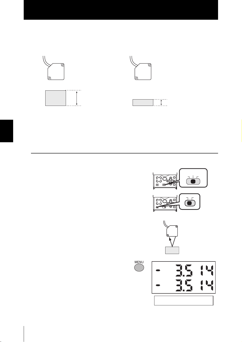
Section4
Threshold Setting
■ TEACHING
Performs measurement and uses the measurement results to set threshold values.
Teaching is useful when threshold samples, i.e., with the upper and lower limits, can be
obtained beforehand.
Sensor Head
Teaching point
= HIGH threshold value
Sensor Head
Teaching point
= LOW threshold value
Threshold sample (lower limit)Threshold sample (upper limit)
Section4 FUNCTIONS AND OPERATIONS USED DURING OPERATION
Hold, trigger, and scaling settings that have been made before teaching are reflected in
the teaching measurements.
The following describes the operation method using the procedure for setting the HIGH
threshold value as an example.
1. Set the mode switch to TEACH.
12
34
TEACH
L
FUNH
RUN
SET
RUNFUN
TEACH
ESC
MENU
2. Switch the threshold switch to “H” to
set the HIGH threshold value.
MENU
12
34
TEACH
FUN
L
H
RUN
ESC
SET
LH
3. Set the workpiece.
4-8
4. Press the MENU key to apply the set-
ting.
The applied threshold value will be
displayed on the sub-display.
ZS-HL
User’s Manual
TEACHMODE
MENU: TEACHING

Section4
Threshold Setting
■ DIRECT IN
The threshold values can be set by directly inputting numerical values. Direct input is
useful when you know the dimensions for an OK judgment or when you want to finetune threshold values after teaching.
The following describes the operation method using, as an example, the procedure for
setting the HIGH threshold value by directly entering it.
1. Set the mode switch to TEACH.
TEACH
ESC
MENU
12
34
TEACH
FUN
L
H
RUN
SET
RUNFUN
2. Switch the threshold switch to “H” to
set the HIGH threshold value.
3. Enter the setting value you want to
change.
The current measured value is
displayed on the main display, and
the offset value is displayed on the
sub-display.
←→ : Change the digit,
↑↓ : Change the value
4. Press the SET key to apply the set-
ting.
If you want to cancel the threshold value
that is being changed, press the ESC
key.
ESC
MENU
12
34
TEACH
SET
FUN
L
H
RUN
TEACHMODE
: DIRECT IN
TEACHMODE
: DIRECT IN
Section4 FUNCTIONS AND OPERATIONS USED DURING OPERATION
LH
ZS-HL
User’s Manual
4-9

Section4
Bank Switching (change of device setup)
Bank Switching (change of device setup)
ZS-HL can hold up to four sets of settings, which are called a bank. When the device setup
is changed, you can switch the bank externally.
• What is bank?
The settings for measurement are held as one bank.
Section4 FUNCTIONS AND OPERATIONS USED DURING OPERATION
SENSING FILTER
OUTPUT I/O SET
Threshold value
• Example of bank switching for settings
If you register settings of various classes,
Setting for product class A
SENSING
OUTPUT I/O SET
Measuring operation
with the contents set
in BANK1
FILTER
Threshold value
BANK1
BANK2
BANK3
BANK4
SENSING FILTER
OUTPUT I/O SET
Register the different settings
for changing the device setup.
Setting for product class B
SENSING FILTER
OUTPUT I/O SET
Switch
to BANK2.
In Multi-Task
mode
It is easy to change the device setup.
Threshold value
BANK
Measuring operation
with the contents set in
BANK2
Threshold value
BANK2
BANK3
BANK4
4-10
ZS-HL
User’s Manual
SENSING
OUTPUT
TAS K4
FILTER
Threshold value
BANK1
TASK1 to TASK4 are
specified in the settings
for each bank.
TASK1
TASKSET
OUTPUT
I/O SET
If only the “threshold value” is different in the settings for a bank, by changing the mode of the bank, you
can increase the number of banks from 4 to 32.
FILTER
Threshold value
TASKSET
Selecting the bank mode p.5-28
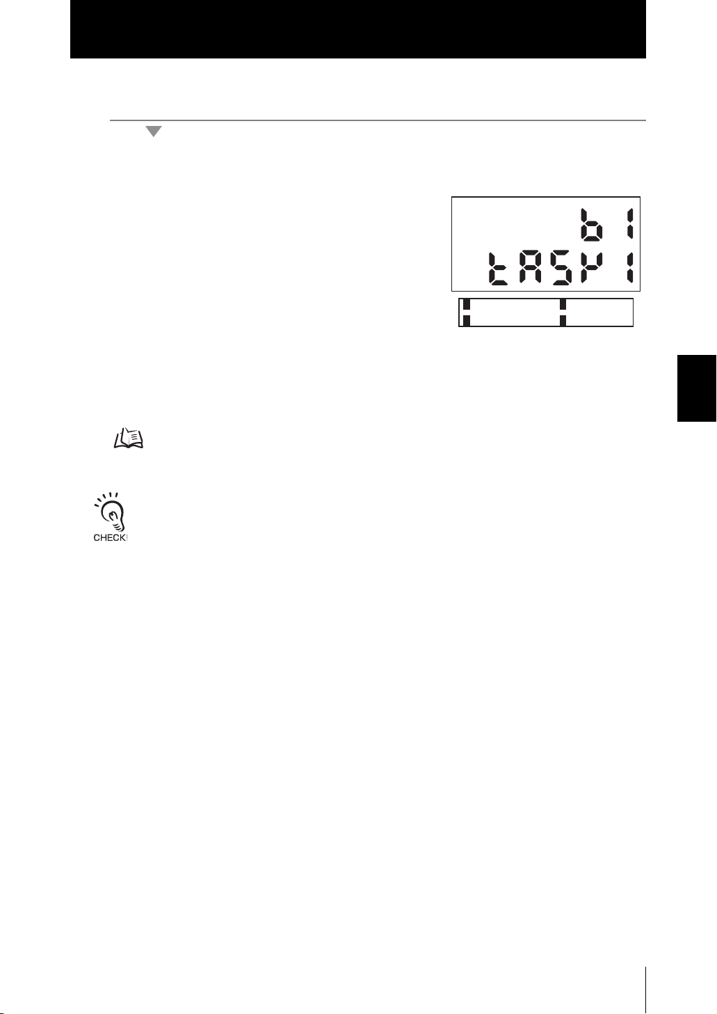
● Bank Switching by Key Operations
X FUN Mode-[BANK]-[CHANGE]
1. Select the bank number.
The current bank number is displayed on the
main display.
Section4
Bank Switching (change of device setup)
1 BANK1
3 BANK3
● Bank Switching by External Signal Input
You need to change the function assignment for input signals.
- Changing the Assignment of Input Signals p.6-17
- Wiring p.2-10
• You can also switch the bank by entering the CompoWay/F or non-procedural command from Smart-
Monitor ZS.
• If the bank mode is set to [JUDGMENT VALUE], the bank cannot be switched at the external signal
input because the number of banks increases to 32.
2 BANK2
4 BANK4
Section4 FUNCTIONS AND OPERATIONS USED DURING OPERATION
ZS-HL
User’s Manual
4-11

Section4 FUNCTIONS AND OPERATIONS USED DURING OPERATION
Section4
Bank Switching (change of device setup)
MEMO
4-12
ZS-HL
User’s Manual

Section5 SETTINGS FOR FUNCTIONS
Basic Operations of Sensor Controller 5-2
Using the Multi-Task Function 5-4
Setting for Sensing Conditions 5-6
Setting the Filter Function 5-12
Setting Output Processing of Sensing Information 5-14
Setting for Measurement of Characteristic Points 5-24
Setting Display Method 5-25
Setting the System Environment 5-27
Changing the Way of Obtaining Banks 5-28
Saving the Settings Data 5-29
Clearing the Settings 5-29
Section5 SETTINGS FOR FUNCTIONS
ZS-HL
User’s Manual
5-1
Section5
Basic Operations of Sensor Controller
Basic Operations of Sensor Controller
Displays and Key Operations
The settings are mainly specified in FUN mode. The LCD screen displays the setup
menus in FUN mode. The No. at the top of each menu corresponds to a function key.
“← → ” displayed at the top right of the LCD screen indicates that the setup menu is made
up of two or more pages. Scroll pages by the LEFT or RIGHT key.
Section5 SETTINGS FOR FUNCTIONS
Key Operations
Alphabet characters that appear on the
digital displays
A B C D E F G H I
H
P
L
LD ON ZERO ENABLE
Main Display
Sub-display
LCD screen
12
34
TEACH
L
FUNH
ESC
MENU
RUN
SET
Control keys
J K L M N O P Q R
S T U V W X Y Z
Top menu in FUN mode
The currently selected bank No. will be displayed on
the main display.
The currently selected task No. will be displayed on
the sub-display.
2
1
SENSING
3
OUTPUT
FILTER
Pressing the MENU key in FUN mode returns to the
display.
Key Role
Function keys Directly sets the No. preceding the items displayed on the LCD screen.
5-2
← LEFT key
→ RIGHT key
The function changes depending on the settings.
- Scrolls pages in list menus.
- Selects the digit of numerical values.
↑ UP key
Changes numerical values during input.
↓ DOWN key
MENU key Displays the top menu.
SET key Applies the item you are setting up.
ESC key Returns to the previous menu.
ZS-HL
User’s Manual

Section5
Basic Operations of Sensor Controller
The following example describes basic operations for changing the measurement mode to
[HI-RESO].
1. Press function key 1 representing
[SENSING].
2. Press function key 1 representing
[MODE].
The currently selected No. is displayed
flashing.
3. Press function key 2 representing
[HI-RESO].
The “Complete!” message is displayed.
4. Press the MENU key to return to the
top menu.
Pressing the ESC key returns to the
previous menu.
1 SENSING
3 OUTPUT
1 MODE
3 GAIN
1 STAND
3 H-SPEED
MODE
Complete!
2 FILTER
2 SETTING
2 HI-RESO
Section5 SETTINGS FOR FUNCTIONS
:HI-RESO
ZS-HL
User’s Manual
5-3

Section5
Using the Multi-Task Function
Using the Multi-Task Function
In the ZS-HLDC Series, you can set multiple measurement processing for one sensing
condition. This measurement processing is called a “task.”
• Application example: Measure the height and surface fluctuation simultaneously.
■ “Single-Task Mode” and “Multi-Task Mode”
Section5 SETTINGS FOR FUNCTIONS
Surface fluctuation (TASK2)
Height (TASK1)
Measuring Multiple Items Simultaneously p.3-8
You can use the two modes appropriately according to the measurement details; for
standard measurement, you can use “Single-Task mode” that can be set easily, and
when you need detailed settings, for example when you measure and judge multiple
characteristic points simultaneously, you can use “Multi-Task mode”. In “Multi-Task
mode”, four tasks are provided. You can measure and judge multiple characteristic
points simultaneously because you can measure the desired characteristic point such
as peak, bottom, and average for each task.
[Single-Task]
Data flow
5-4
SENSINGSENSING
[Multi-Task]
ZS-HL
User’s Manual
MEASUREMENT POINT
MEASUREMENT POINT
FILTER
SCALING
Data flow of TASK1
SCALING
SCALING
HOLD
HOLD
FILTER
Data flow of TASK4
FILTER
HOLD
Zero reset
JUDGE
Zero reset
JUDGE
Zero reset
JUDGE
* Output
•
Linear output
Select one TASK that you want to output.
• Judgment output
-
Select one TASK that you want to output.
*OUTPUT OUTPUT*OUTPUT
-
When ZS-RPD is connected, you can
output a judgment for four TASKs.
• Terminal block output
If you connect ZS-RPD, you can
output data for up to four TASKs.
•
Digital output (USB/RS-232C)
Continuously outputs four TASKs.
It is used to display a
graph screen or do
logging with SmartMonitor
ZS or external devices.

Section5
Using the Multi-Task Function
Switching to Multi-Task Mode
Select “Single-Task mode” when you perform one measurement processing for
onesensing, and select “Multi-Task mode” when you measure and judge multiple
characteristic points simultaneously.
X FUN Mode-[SYSTEM]-[MULTI-TASK]
Setting Description
OFF Single-Task mode is selected. (default value)
ON Multi-Task mode is selected.
Differences in the menu tree according to the mode p.16
Selecting Tasks
When you set [MULTI-TASK] to ON, select the task number and then specify the various
settings. The following describes the method of selecting the task number.
Section5 SETTINGS FOR FUNCTIONS
X FUN Mode
1. Press the MENU key to display the
TOP menu.
2. Press the ESC key.
The TASK selection menu will be
displayed.
3. Select the task number.
The currently selected task is displayed
on the sub-display.
1 SENSING
3 FILTER
1 TASK1
3 TASK3
2 MEASURE
2 TASK2
4 TASK4
ZS-HL
User’s Manual
5-5

Section5
Setting for Sensing Conditions
Setting for Sensing Conditions
Set the conditions to be used for detecting workpieces by the sensor.
Setting Measurement Mode
■ Setting the Measurement Mode
Section5 SETTINGS FOR FUNCTIONS
Set the measurement mode according to the measurement details (such as moving
speed and measurement point of workpiece).
Select the measurement mode based on the items (e.g. speed, precision, or sensitivity)
that you want to give priority to in measurement.
X FUN Mode-[SENSING]-[MODE]
Setting Description
STAND This is the standard measurement mode.
(sampling frequency: approx. 500 µs)
HI-RESO Select this mode to measure workpieces with sensitivity set high. (default
value)
(sampling frequency: approx. 2 ms)
HI-SPEED Select this mode to measure workpieces at high speed.
However, you cannot select this menu in Multi-Task mode.
(sampling frequency: the fastest speed of approx. 110 µs)
HI-SENS Select this mode to measure workpieces with sensitivity set high. In this
measurement mode, sensitivity to received light is much better than the
High-Resolution mode as the sampling time is longer.
(sampling frequency: approx. 4 ms)
5-6
ZS-HL
User’s Manual
• In High-Speed mode, the sampling cycle changes according the actual settings. (When only the
average count is set, the sampling cycle becomes the maximum speed (approx. 110 µs).)
Check the actual sampling cycle at [INFO]-[CYCLE] from the top menu.
• In High-Speed mode, the smooth function is changed to OFF. In modes other than High-Speed
mode, the smooth function is changed to ON.

Section5
Setting for Sensing Conditions
■ Setting Custom Mode
If you cannot perform measurement in the provided measurement modes, use Custom
mode.
You can change additional lines and exposure time, so that a measurement can be performed under conditions suitable for the surface status of the workpiece.
Set in the order of [LINE] → [EXPOSE] → [SKIP].
If you set an additional line, its exposure time is automatically determined. If the light amount is still
insufficient, set the exposure time. When [SKIP] is set to ON in this state, the effective line width is
doubled.
X FUN Mode-[SENSING]-[MODE]
Setting Description
CUSTOM
LINE
(number of
additional lines)
Set this item to make it mode difficult (increase the number of additional lines)
for measurement to be influenced by the state of the workpiece surface, or to
measure at a single pinpoint on the workpiece (reduce the number of additional lines).
Range: 1 to 200
(The maximum number of lines changes according to the exposure time setting.)
Usage Width of Line Beam p.8-20
Section5 SETTINGS FOR FUNCTIONS
EXPOSE
(exposure time)
SKIP Set this item to extend the measurement line width without changing the mea-
Set this item when exposure is insufficient and the exposure time must be
lengthened to increase the amount of received light.
- For Single mode
Range: 0.2 ms to 20 ms
- For Multi-mode
Range: 0.5 ms to 20 ms
When the internal measurement time is longer than the exposure
time setting, the exposure time (= sampling cycle) sometimes is
greater than the setting.
Check the actual sampling cycle in [SYSTEM]-[INFO]-[CYCLE].
suring time.
The effective line width is doubled when this setting is ON.
Range: ON, OFF
Setting GAIN
You can set the CMOS gain so that even workpieces having an extremely low amount of
reflected light or workpieces having a large tilt can be measured stably.
The measurement resolution sometimes drops when a large gain is set. Also, this function increases the
gain on the light receiving side. Therefore, please note that the Sensor Controller can be easily affected
by ambient light.
X FUN Mode-[SENSING]-[GAIN]
Setting Description
1, 2, 3, 4, 5 Adjusts the internal gain of the CMOS image sensor. (default value: 1)
1 (gain small) → 5 (gain large)
User’s Manual
ZS-HL
5-7

Section5
Setting for Sensing Conditions
Setting Head Installation
Set how the Sensor Head is installed.
This setting is automatically specified according to the type of the connected Sensor
Head. However, if the Head is installed at an angle and the default value and reflection
angle are changed, change the settings according to the status of the head installation.
X FUN Mode-[SENSING]-[SETTING]
Setting the Emitted Light Amount
Set the amount of light emitted from the Sensor Head to match the state of the workpiece
Section5 SETTINGS FOR FUNCTIONS
surface.
Setting Description
DIFFUSE Select this item when the Sensor Head is installed for diffuse reflection sensing.
REGULAR Select this item when the Sensor Head is installed for regular reflection sensing.
The response may slow down if workpieces having differing reflection factors such as black-and-white
workpieces are measured with FUN mode set to [AUTO]. In this case, narrow the adjustment range by
setting [RANGE]. If this does not increase the response speed to keep up with measurement, select
[FIXED].
X FUN Mode-[SENSING]-[LASER]
Setting Description
AUTO Automatically adjusts the emitted light amount according to the reflection
factor of the workpiece. Note that the response time varies with each measurement. (default value)
RANGE UPPER
LOWER
FIXED Sets the emitted light amount to a fixed value.
Sets the adjustment range for the AUTO setting.
If the response speed cannot keep up with measurement at the default
value, narrow the range.
Range: 0.1 to 80 % (default: LOWER 0.1 %, UPPER 80 %)
Level Sensitivity Color of workpiece
0.1 %
•
•
80 %
For reference levels, see [RANGE].
Range: 0.1 % to 80 %.
Low
High
Bright
Dark
5-8
ZS-HL
User’s Manual

Section5
Setting for Sensing Conditions
Setting Measurement Object
Set the type of workpiece to be measured.
In Multi-Task mode, [THICK] is not displayed.
X FUN Mode-[SENSING]-[OBJECT]
Setting Description
STAND Usually, select this setting. (default value)
PCB Select this setting for workpieces such as PCBs through which light penetrates.
MIRROR Select this setting for workpieces having a mirror surface.
Glass Mode1 Select this mode to measure glass at high speed.
(This is not displayed in Multi-Task mode.)
Glass
Mode2 Select this mode when you want to measure glass stably.
This is effective when measuring the thickness of glass having different reflection
factors on the front side and the backside such as backside deposited glass.
(This is not displayed in Multi-Task mode.)
Section5 SETTINGS FOR FUNCTIONS
Front side
Backside
When MODE2 is selected, two areas are measured and the measured value that is
closer to the Sensor Head is output as the result of the front side of the glass.
When MODE2 is selected, the measurement area is set for the front side and backside of the glass respectively, and an adjustment is performed for a suitable
received light amount for each area.
When you use SmartMonitor ZS, you can adjust the area while checking the
received light amount.
Glass with a film
For example, backside
deposited glass.
Mode 1 Mode 2
Automatically
adjusts the
received light
amount.
Area of the front side
Received light amount of the front side
Received light amount of the backside
Area of the backside
ZS-HL
User’s Manual
5-9

Section5
Setting for Sensing Conditions
Setting Description
THICK Mode1 Select this mode to measure the thickness of glass at high speed.
Measures the thickness between and .
(This is not displayed in Multi-Task mode.)
Section5 SETTINGS FOR FUNCTIONS
Front side
Backside
Mode2 Select this mode when you want to measure the thickness of glass stably.
This is effective when measuring the thickness of glass having different reflection
factors on the front side and the backside such as backside deposited glass.
(This is not displayed in Multi-Task mode.)
Front side
Backside
When MODE2 is selected, the measurement area is set for the front side and backside of the glass respectively, and an adjustment is performed for a suitable
received light amount for each area.
When you use SmartMonitor ZS, you can adjust the area while checking the
received light amount.
Raw glass
Glass with a film
Mode 1 Mode 2
Automatically
adjusts the
received light
amount.
Measure the thickness.
Measure the thickness.
For example,
backside deposited glass.
5-10
ZS-HL
User’s Manual
Area of the front side
Received light amount of the front side
Received light amount of the backside
Area of the backside
When you set GLASS (MODE2) or THICK (MODE2) for the measurement object, the following parame-
ters are initialized.
•SMOOTH
• AVERAGE

Section5
Setting for Sensing Conditions
Setting Mutual Interference Prevention
Mutual interference between two Sensor Heads can be prevented by shifting the laser
beam emission timing. Use this function when Sensor Heads must be set up inside an
area where mutual interference is likely to occur or when a transparent workpiece will be
measured sandwiched between two Sensor Heads.
Sensor Head 1
Timing A
Glass
H
P
L
LD ON ZERO ENABLE
H
P
L
LD ON ZERO ENABLE
H
P
L
LD ON ZERO ENABLE
Sensor Head 2
Timing B
X FUN Mode-[SENSING]-[SYNC]
Setting Description
OFF The mutual interference prevention function is not used. (default value)
ON Timing A Sets the light emission timing to timing A.
Timing B Sets the light emission timing to timing B.
The sampling frequency is changed when the mutual interference prevention mode is enabled.
• 8 times in Standard, High-Resolution and High-Sensitivity modes
• About 15 times in the High-Speed mode
The measurement cycle is also influenced by other settings.
Check the sampling cycle in FUN Mode-[SYSTEM]-[INFO]-[CYCLE].
• The same sensing mode must be set to each controller when the mutual interference prevention mode
is used. When [HI-SPEED] or [CUSTOM] is selected as the measurement mode, the same conditions
must be set. Setting different conditions will result in a sampling cycle on each controller and mutual
interference can no longer be prevented.
• When GLASS (MODE2) or THICK (MODE2) is set, mutual interference prevention function does not
operate.
Section5 SETTINGS FOR FUNCTIONS
ZS-HL
User’s Manual
5-11

Section5
.
Setting the Filter Function
Setting the Filter Function
Set the conditions for filtering information obtained from the sensor.
Waveform
when filter
function is
not set
Displacement
Smooth
SMOOTH
Average
value
Differentiation
Section5 SETTINGS FOR FUNCTIONS
Setting SMOOTH
The intermediate value of multiple sets of data can be output as the measurement result.
This function removes any abnormal values such as spiking that occur when the shape of
the workpiece suddenly changes during measurement.
Example: To remove spiking
Displacement
0
Spike-like changes are
removed.
Changes are smoothed out.
Changes are extracted to
eliminate displacement value
Abnormal values such as spiking that occur when the shape
of the workpiece suddenly changes during measurement.
5-12
Measured valueMeasured value
The smoothing function can remove spikes
Time
Time
X FUN Mode-[FILTER]-[SMOOTH]
Setting Description
OFF The smooth function is not used.
ON The intermediate value of the past 15 measured values is set as the measurement
result at each sampling cycle. (default value)
When “HI-SPEED” is set in the measurement mode, [OFF] is set.
ZS-HL
User’s Manual

Section5
Setting the Filter Function
Setting AVERAGE
The average of the measured values obtained based on the preset number of samples
can be output. Select this setting when you want to ignore sudden changes in measured
values.
X FUN Mode-[FILTER]-[AVERAGE]
Setting Description
1, 2, 4, 8, 16, 32, 64, 128, 256, 512,
1024, 2048, 4096
(When the mode is set to HighSpeed mode, the value is from 1 to
256.)
Sets the average count. (default value: 128)
Setting Differentiation
Use the differentiation function to detect only sudden changes in the measured values that
occur during very short periods of time.
The differentiation function detects changes between the present value and the measured
value that is in effect just before the comparing pitch. The coefficient of this comparing
pitch is defined as the differentiation cycle.
Example: Differentiation cycle=10 ms
Present value
Sampling
Sampling cycle
Comparison interval 10 ms
Display value
(differentiation result)
Section5 SETTINGS FOR FUNCTIONS
X FUN Mode-[FILTER]-[DIFF]
Setting Description
OFF The differentiation function is not used. (default value)
ON Sets the cycle (ms) in which to perform differentiation.
Range: 1 to 500
ZS-HL
User’s Manual
5-13

Section5
Setting Output Processing of Sensing Information
Setting Output Processing of Sensing Information
Set how sensing information is to be processed for outputting the required values.
Setting the Scaling
This setting is used when you want to correct any errors that are generated due to the
installation status of the Sensor Head, and display the corrected value on the main display.
Place an actual sensing object in position for measurement.
There are three setting modes: “manual setting of correction values,” and “one-point
scaling” and “two-point scaling” that automatically set the correction values of a placed
sensing object.
When GLASS mode is selected for the measurement object, the menu used only for
scaling is displayed.
Section5 SETTINGS FOR FUNCTIONS
Measuring the Thickness of Transparent Objects p.3-4
The settings listed below return to the default settings when scaling is set. Set these items after scaling
settings have been completed.
• Zero reset
■ Setting One-point Scaling
Measurement is performed at one position and offset values are set for that measurement value.
The offset and increment/decrement inversion (display inversion) can be set.
Example: Displaying the height of the sensing object
Measuring center
distance
Measured value
-4.5 mm
Sensor Head
Sensing
object
Target display value
10 mm
-4.5
Display value
(mm)
10
Measured value
(mm)
-4.5
5-14
ZS-HL
User’s Manual

Setting Output Processing of Sensing Information
X FUN mode-[OUTPUT]-[SCALING]-[ON]-[AUTO]
1. Set the sensing object in place, and enter the
desired setting to be used as the offset.
The current measured value is displayed on the
main display, and the offset value is displayed
on the sub-display.
2. Press the SET Key to apply the setting.
3. Set the decimal point to determine the effec-
tive digits.
Section5
INPUT POINT 1
VAL SET:OKDIG
The decimal point set here becomes the new deci-
mal point of the scaling setting.
The position of the decimal point on the display fol-
lows the “DOT” setting of the display setup in RUN
mode.
4. Press the SET Key to apply the setting.
5. Press the SET key without entering any
value for the second point.
6. [Select [FORWARD] or [INVERS].
FORWARD: The larger the distance between the Sensor Head and the sensing object, the
larger the measured value displayed on the Sensor Controller.
INVERS : The larger the distance between the Sensor Head and the sensing object, the
smaller the measured value displayed on the Sensor Controller.
Section5 SETTINGS FOR FUNCTIONS
INPUT DOT POINT
VAL SET:OKDIG
INPUT POINT 2
VAL SET:OKDIG
CHANGE DIRECTION
1 FORWARD 2 INVERS
ZS-HL
User’s Manual
5-15

Section5
Setting Output Processing of Sensing Information
■ Setting Two-point Scaling
Measurement is performed at two positions and offset values are set for those measured values.
Section5 SETTINGS FOR FUNCTIONS
Example:
Sensor Head
Sensing
object
Sensor Head
Sensing
object
Correcting display values to match actual distances
Display value
4.0
3.8
Actual distance:-3.0 mm
Display value:-2.8 mm
Actual distance:4.0 mm
Display value:3.8 mm
-3.0
(mm)
-2.8
-3.0
4.0
Measured
value (mm)
5-16
ZS-HL
User’s Manual
Separate the two specified points by at least 1 % of the rated measurement range for the connected
Sensor Head.
Example: For the ZS-LD80 (diffuse reflection type)
The two measured points must be separated by at least “30 mm × 0.01 = 0.3 mm” as the measuring
range is “30 mm ±15 mm”.

Setting Output Processing of Sensing Information
X FUN Mode-[OUTPUT]-[SCALING]-[ON]-[AUTO]
1. Set the first point by following steps 1 to 4 of
the one-point scaling procedure.
Section5
INPUT POINT 1
2. Place the sensing object at the position (sec-
ond point) to perform scaling, and enter the
desired offset value (second point).
Press the LEFT key. The sub-display blinks.
3. Press the SET Key to apply the setting.
■ Manual Setting
Enter numerical values for scaling correction values.
X FUN Mode-[OUTPUT]-[SCALING]-[ON]-[MANUAL]
Setting Description
SPAN Sets the inclination of the sensor characters as a coefficient.
Range: -2.0 to 2.0
Measurement value
(mm)
2.0
INPUT POINT 2
Workpiece
displacement
VAL SET:OKDIG
Section5 SETTINGS FOR FUNCTIONS
VAL SET:OKDIG
-2.0
OFFSET Adds/subtracts a fixed value to or from the measured value.
Range: -999.99 to 999.999
Measurement value
(mm)
Workpiece
displacement
ZS-HL
User’s Manual
5-17

Section5
Setting Output Processing of Sensing Information
Setting HOLD Functions
Set the hold conditions for measured values. The hold functions hold any value from the
measured values during the specific period (sampling period), such as the maximum or
minimum value.
■ TYPE
Section5 SETTINGS FOR FUNCTIONS
Set the hold conditions for measured values.
X FUN Mode-[OUTPUT]-[HOLD]-[TYPE]
Setting Description
OFF Hold measurement is not performed. The measured value is output at all
times. (default value)
PEAK Holds the maximum value during the sampling period. The output
changes at the end of the sampling period and is held until the end of the
next sampling period.
Max. value
Current
measured value
Output
Sampling period
BOTTOM Holds the minimum value during the sampling period. The output changes
at the end of the sampling period and is held until the end of the next sampling period.
Current
measured value
Sampling period
P-P Holds the difference between the maximum and minimum values during
the sampling period. This option is selected mainly when detecting vibration. The output changes at the end of the sampling period and is held
until the end of the next sampling period.
Max. value
Current
measured value
Sampling period
AVERAGE Holds the average measured value during the sampling period. The out-
put changes at the end of the sampling period and is held until the end of
the next sampling period.
Current
measured value
Min.
value
Min.
value
Output
Output
(max. value - min.
value)
Output
(average)
5-18
ZS-HL
User’s Manual
Sampling period

Section5
Setting Output Processing of Sensing Information
Setting Description
SAMPLE Holds the measured value at the start of the sampling period. The output
changes at the start of the sampling period and is held until the start of the
next sampling period.
Current
measured value
Sampling period
Output
■ Triggers
Set the input method for the timing of the start and end of the measurement period.
X FUN mode-[OUTPUT]-[HOLD]-[TRIGGER]
Setting Description
EXT Enters the trigger for the start of sampling by using the timing input. The period
that the timing signal is ON is the sampling period.
(default value)
Timing input
When a delay time is set, the input OFF timing and the end of the
sampling period will not be synchronous. Sampling will end after the
specified sampling period has elapsed.
ON
OFF
Sampling period
Section5 SETTINGS FOR FUNCTIONS
SELF-UP The sampling period is the period at which the measured value is greater than
the specified self-trigger level. Hold measurement is possible without a sync
input.
Self-trigger level
Measured
value
Sampling period Sampling period
When SELF-UP is selected, the following items are subsequently displayed:
•TRG LEVEL
Sets the desired self-trigger level.
Range: -999.99 to 999.999
• TRG HYS
Sets the hysteresis width for the self-trigger.
Range: 0 to 999.999
When a delay time is set, the timing when the measured value
becomes smaller than the self-trigger level and the end of the sampling period will not be synchronous. Sampling will end after the specified sampling period has elapsed.
Hysteresis width
(for self-trigger)
Action point
Return point
ZS-HL
User’s Manual
5-19
Section5
Setting Output Processing of Sensing Information
Section5 SETTINGS FOR FUNCTIONS
Setting Description
SELF-DN The sampling period is the period at which the measured value is smaller than
the specified self-trigger level. Hold measurement is possible without a sync
input.
Measured value
Self-trigger level
Sampling period
When SELF-DN is selected, the following items are subsequently displayed:
•TRG LEVEL
Sets the desired self-trigger level.
Range: -999.99 to 999.999
• TRG HYS
Sets the hysteresis width for the self-trigger.
Range: 0 to 999.999
When a delay time is set, the timing when the measured value
becomes greater than the self-trigger level and the end of the sampling period will not be synchronous. Sampling will end after the specified sampling period has elapsed.
Hysteresis width
(for self-trigger)
Action point
Return point
Set the hysteresis width based on the fluctuations in the measured values around the trigger level.
The hysteresis will be applied from the start of the sampling period and will prevent timing input
chattering.
5-20
ZS-HL
User’s Manual

Section5
Setting Output Processing of Sensing Information
■ DELAY
A delay time is set to ignore measured values immediately after the timing input. This is
useful for avoiding bounding during device startup and the influence of machine vibration.
The delay time (the delay between timing input and the start of sampling) and the sampling period can be set.
Delay time Sampling period
Timing input
ON
OFF
Ignored
X FUN mode-[OUTPUT]-[HOLD]-[DELAY]
Setting Description
OFF The delay time is not set. (default value)
ON Sets the delay time.
When ON is selected, the following items are subsequently displayed:
•T-DELAY
Sets the delay time.
Range: 0 to 9000 (ms)
•T-TIME
Sets the sampling period.
Range: 1 to 9000 (ms)
Set so that the “delay time + sampling period” is less than the timing
input ON interval. If the next timing input for measurement is received
before the “delay time + sampling period” has elapsed, that timing
input will be ignored and will not be reflected in the sampling.
Delay time
Accepted
Section5 SETTINGS FOR FUNCTIONS
ZS-HL
User’s Manual
5-21

Section5
Setting Output Processing of Sensing Information
Setting the Zero Reset Function
■ TYPE
Set how zero reset is to be executed.
X FUN Mode-[OUTPUT]-[0RESET]-[TYPE]
Setting Description
REAL Sets the measured value when a zero reset is executed to zero. (default value)
Measurement of height
from reference surface
Section5 SETTINGS FOR FUNCTIONS
■ OFFSET
■ STATUS
Zero reset
HOLD Sets the measured value (hold value) when a zero reset is executed to zero.
This setting is enabled when hold measurement is performed.
Zero reset
Reference A
Hold A
(reference)
Measurement of height
from reference surface
Direction of movement
Set an offset to set the reference value for zero reset to a value other than 0.
X FUN mode-[OUTPUT]-[0RESET]-[OFFSET]
Setting Description
OFFSET Sets the reference value.
Range: -999.999 to 999.999 (default value: 0)
Set valid/invalid for the zero reset function.
5-22
X FUN mode-[OUTPUT]-[0RESET]-[STATUS]
Setting Description
ON When a zero reset input is received externally, a zero reset is executed.
(Default Value)
OFF Even when a zero reset input is received externally, a zero reset is not exe-
cuted.
In Multi-Task mode, set ON/OFF for each TASK.
ZS-HL
User’s Manual

Section5
Setting Output Processing of Sensing Information
■ 0RESET MEMORY
You can select whether or not to hold the measured value zero reset level even if the
power is turned OFF.
X FUN Mode-[SYSTEM]-[0RESET]
Setting Description
OFF Zero reset is canceled when the power is turned OFF. (default value)
ON The zero reset level is saved to memory even if the power is turned OFF.
Turn [OFF] zero reset memory if, as in the example below, the zero point is reset for
each measurement.
Example: When the step of the sensing object is measured
Sensor Head
This step
is measured.
Section5 SETTINGS FOR FUNCTIONS
Zero reset
executed
Direction of movement
• If zero reset memory is [ON], the zero reset level data will be written in the Sensor Controller non-
volatile memory (EEPROM) at each zero reset. The EEPROM can be written a maximum of
100,000 times. Writing the zero reset level for each measurement can, therefore, use up the life of
the memory and lead to malfunctions.
• Even if zero reset memory is enabled, the zero reset level will be held also when it is saved. Zero
reset will continue after startup when these functions have been changed.
Zero reset
executed
Zero reset
executed
ZS-HL
User’s Manual
5-23

Section5
Setting for Measurement of Characteristic Points
Setting for Measurement of Characteristic Points
You can measure any measurement points within the range of received light by using the
line beam characteristics and multi-task function. Set this menu when you measure subtle
concavity and convexity in the workpiece or thickness of a transparent object.
The setting for measuring the characteristic points are valid only in Multi-Task mode.
X FUN Mode-[MEASURE]-[Measured value]
Setting Description
NONE Does not set measurement points.
AVERAGE Measures the average position between the peak
and bottom positions of the line beam.
You can measure the distance from the workpiece. (default value)
Line beam
Average
Section5 SETTINGS FOR FUNCTIONS
PEAK Measures the peak position of the line beam.
You can measure the highest position in the line
beam.
BOTTOM Measures the bottom position of the line beam.
You can measure the lowest position in the line
beam.
THICK Measures the thickness of a transparent object
such as glass.
STEP Measures between peak and bottom in the line
beam.
You can detect subtle concavity and convexity in
the workpiece.
K+mX+nY(calculation) Select this to perform logic operations on X and Y with the coefficient freely set. In
addition, you can assign, to TASK, the measurement of characteristic points you
have set, and measure multiple points or perform calculations.
• K range: -999999 to 999999
• m range: -10.0 to 10.0
• n range: -10.0 to 10.0
• X range: NONE, TASK1 to TASK4
• Y range: NONE, TASK1 to TASK4
Line beam
Peak
Line beam
Bottom
Thickness
Line beam
Peak/bottom
5-24
ZS-HL
User’s Manual

Section5
Setting Display Method
Setting Display Method
Set what you want to display on the Sensor Controller during measurement in RUN mode.
To set the display method, switch to RUN mode and display the top menu.
Setting the Digital Display
Set what is displayed on the display in RUN mode.
■ Number of digits past the decimal point
Set the number of display digits in the main display and sub-display.
When five or less digits are set, the digits are disabled from the rightmost digit first.
X RUN Mode-MENU key-[DIGITAL]-[DOT]
Setting Description
5th, 4th, 3rd, 2nd, 1st, 0 Sets the number of display digits past the decimal point.
(default value: varies depending on the connected Sensor Controller.)
Section5 SETTINGS FOR FUNCTIONS
■ Setting the ECO display
Set the brightness of the main display and sub-displays.
X RUN Mode-MENU key-[DIGITAL]-[ECO]
Setting Description
NORMAL Sets the display to normal brightness. (default value)
ECO Suppresses the brightness by reducing current consumption to darken the display.
OFF Turns the display OFF.
Displaying HELP
Display Help for the functions assigned to the SET or ESC keys in RUN mode.
X RUN Mode-MENU Key-[HELP]
ZS-HL
User’s Manual
5-25

Section5
Setting Display Method
Setting the LCD Screen
Set how the LCD screen is displayed in RUN mode.
■ Setting display ON/OFF
Set whether or not to display the LCD screen.
X RUN Mode-MENU key-[LCD]-[ON/OFF]
Setting Description
ON Displays the LCD screen at all times. (default value)
AUTOOFF Turns the LCD screen display OFF when no operations are performed for one
minute.
OFF Turns the LCD screen OFF.
(This setting is valid only in RUN mode. Note, however, that pressing the MENU key
displays the display customize menu.)
Section5 SETTINGS FOR FUNCTIONS
■ Setting the backlight ON/OFF
■ Customizing the LCD display
Set whether or not to turn the LCD screen’s backlight ON or OFF.
X RUN Mode-MENU key-[LCD]-[B.LIGHT]
Setting Description
ON Turns the LCD screen backlight ON at all times. (default value)
AUTOOFF Turns the backlight OFF when no operations are performed for one minute.
OFF Turns the LCD screen backlight OFF.
Set this item to display customized characters on the LCD screen.
X RUN Mode-MENU key-[LCD]-[CUSTOM]
Setting Description
UPPER Set this item to ON to display characters set at [U-CUST] on the upper section of the
LCD screen. (default: U-OFF)
LOWER Set this item to ON to display characters set at [L-CUST] on the lower section of the
LCD screen. (default: L-OFF)
U-CUSTM Use this setting to edit characters to display on the LCD screen. (max. 16 digits)
Call up the initial character of each character group using function keys 1 to 4.
1: A to Z
2: a to z
3: KANA (Japanese Characters)
L-CUSTM
4. Numbers, :, ;, , <, =, >, ?, @
Switch the characters in order using the UP or DOWN key.
Move the digits by the LEFT or RIGHT key.
To clear a character, select a space.
5-26
ZS-HL
User’s Manual
 Loading...