


Cat. No. Z232-E1-02
Smart Sensors
ZS Series
Non-procedual Communication
Command Reference

Introduction
Thank you for purchasing the ZS Series.
This manual provides reference information on non-procedural communication commands
for ZS Series.
This manual provides information for the following models and versions.
Model Firmware Version
ZS-LDC v2.000 or later
ZS-HLDC v1.000 or later
ZS-MDC v2.000 or later
ZS-DSU v2.000 or later
Different firmware versions may cause communication errors, unintended setting
overwrite, and damages on the controller. Please make sure to use the controller with the
correct software version.
If your software version is not listed in the table above, please update the software using
the SmartMonitorZS firmware update software, such as WarpEngineZS, to match the
software version.
When using the ZS Series, be sure to observe the following:
• The ZS Series must be operated by personnel knowledgeable in electrical engineering.
• To ensure correct use, please read this manual thoroughly to deepen your understanding of the product.
• Please keep this manual in a safe place so that it can be referred to whenever necessary.

Contents
Contents
Setting the Communication Specifications ................................................... 2
Format.......................................................................................................... 3
List of Non-procedural Commands .............................................................. 4
List of Parameters (ZS-LDC) ........................................................................ 7
List of Parameters (ZS-HLDC) ................................................................... 12
List of Parameters (ZS-MDC) ..................................................................... 20
List of Parameters (ZS-DSU) ..................................................................... 25
FLOWDATA Reference .............................................................................. 30
Capturing Image Data ................................................................................ 36
Example of Usage ...................................................................................... 38
Revision History ......................................................................................... 42
Non-procedural Communication Command Reference
ZS-Series
1

Setting the Communication Specifications
Setting the Communication Specifications
Change the settings of the controller communication specifications for non-procedural
communication with the external device.
Use USB cable or RS-232C cable to connect ZS Series controllers to external devices. For USB cable
connection, install Smart Monitor ZS and USB driver beforehand. After installing Smart Monitor ZS, USB
ports are recognized as standard COM ports, and communication is achieved as with the RS-232C.
(Setting the communication specifications including baud rate is not necessary.) For details on how to
connect cable, refer to the User's Manual for each controller.
1.Set the mode switch to "FUN".
2.Select [System] - [Communication] - [Mode] menu.
3.Select [non-procedural].
4.For RS-232C cable connection, select [System] - [Communication] - [RS-232C]
menu to set the appropriate communication specifications for the external
device.
5.Save the settings.
If you are connecting multiple controllers, set all controllers other than ZS-HLDC to [non-procedural].
Note that the communication with SmartMonitor ZS is not available in [non-procedural] mode. If you
want to communicate with SmartMonitor ZS, reset to [CompoWay/F] communication.
ZS-Series
2
Non-procedural Communication Command Reference

Format
The format of non-procedural commands are as follows:
Example: A command to acquire a measured value MEASURE command
* Each character is output as an ASCII code (except for FLOWDATA response).
MEASURE OCR
Format
Space
Delimiter
The format of returned values changes depending on the command.
For the description of each command, refer to "List of Non-procedural Commands"
section.
•MEASURE / M / DATAGET
The returned value consists of right aligned 11 characters and a delimiter. The unit is
nm for a displacement value. Shortfalls of the characters are filled with spaces from
the left.
Example: The returned value is -30.719923 mm.
-30719923CR
•BANKGET command
The returned value is output as 1 character bank No.
Example: The bank No. is 2.
1CR
•VERGET command
The returned value is output in the following format:
ZS - LDC 2 . 0 0 0CR
Version
•Other commands
Either OK or ER is returned according to the result of the command. The command
was executed properly:
OKCR
The command was not executed properly or the setting was NG:
ERCR
The delimiter can be selected from the following three types.
CR/LF/CR+LF
ZS-Series
Non-procedural Communication Command Reference
3
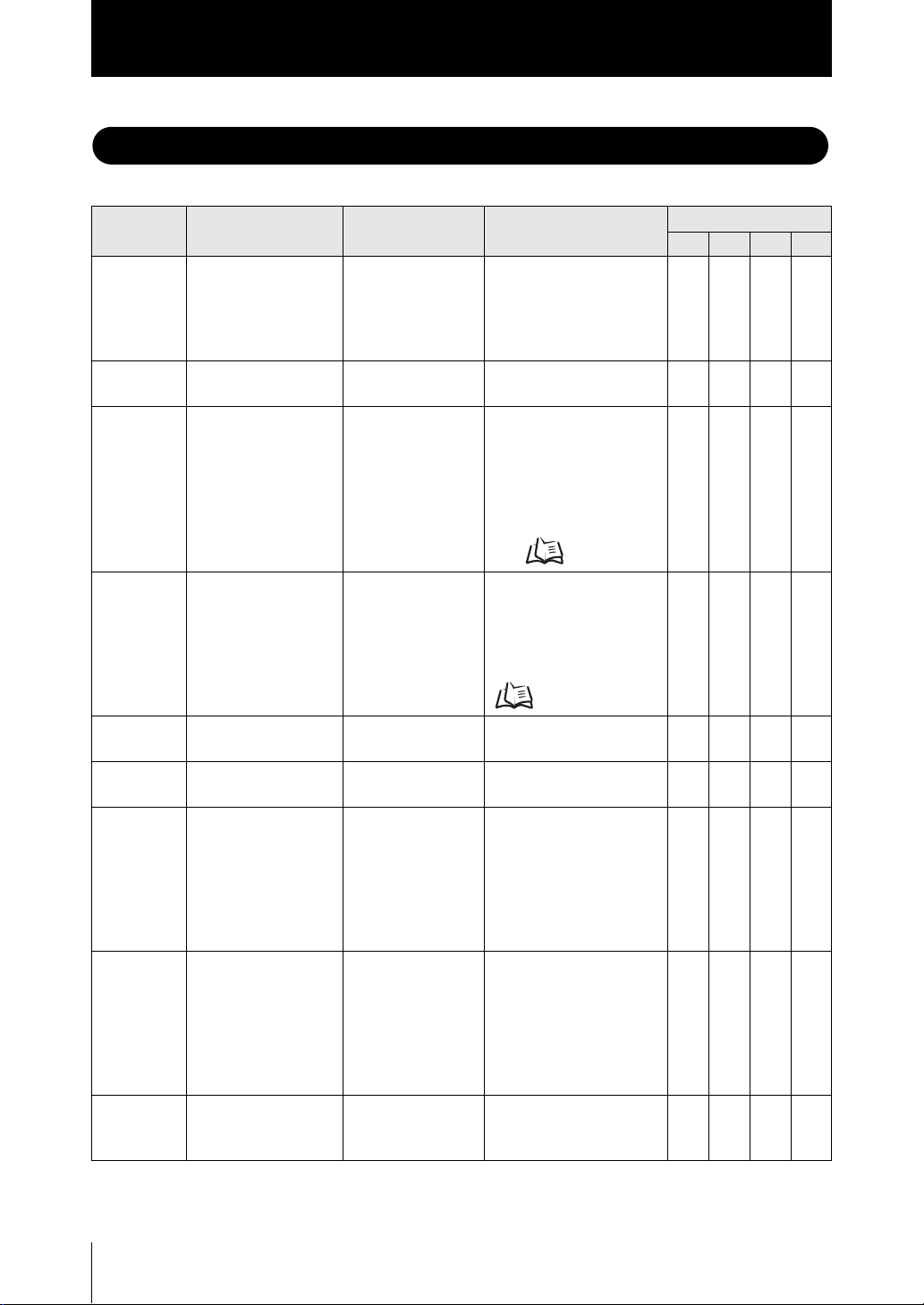
List of Non-procedural Commands
List of Non-procedural Commands
Command
name
MEASURE MEASURE
M M <Task No.>
DATAGET DATAGET <Unit No.>
DATASET DATAGET <Unit No.>
BANKGET BANKGET<delimiter> <Bank No.>
BANKSET BANKSET<Bank No.>
ZERORST ZERORST
ZEROCLR ZEROCLR
DATASAVE DATASAVE
Format Returned value Description
<measured value>
<Task No.>
<delimiter>
<delimiter>
<Data No.>
<delimiter>
<Data No.>
<Setting value>
<delimiter>
<delimiter>
<Task No.>
<delimiter>
<Task No.>
<delimiter>
<delimiter>
<delimiter>
<measured value>
<delimiter>
<Data>
<delimiter>
OK <delimiter>
ER <delimiter>
<delimiter>
OK <delimiter>
ER <delimiter>
OK <delimiter>
ER <delimiter>
OK <delimiter>
ER <delimiter>
OK <delimiter>
ER <delimiter>
Acquires a measured
value.
If <Task No.> is omitted, it
aqcuires the displayed
measured value.
Same as MEASURE
command.
Acquires measurement
data or setting data of the
processing unit.
* For details of numbers,
refer to "List of
Parameters."
p.7
Changes setting data of
the processing unit.
* For details of numbers,
refer to "List of
Parameters."
p.7
Acquires the current bank
No.
Switches to the designated
bank No.
Executes a zero-reset. If
<Task No.> is omitted, it
executes on the task
currently displayed as a
result. If <Task No.> is set
to 4, it executes on all the
tasks.
Cancels a zero-reset. If
<Task No.> is omitted, it
executes on the task
currently displayed as a
result. If <Task No.> is set
to 4, it executes on all the
tasks.
Saves all the bank data on
the flash memory of the
controller.
Support
HLDC
LDC
Yes Yes Yes Yes
Yes Yes Yes Yes
Yes Yes Yes Yes
Yes Yes Yes Yes
Yes Yes Yes Yes
Yes Yes Yes Yes
Yes Yes Yes N o
Yes Yes Yes N o
Yes Yes Yes Yes
MDC DSU
ZS-Series
4
Non-procedural Communication Command Reference

List of Non-procedural Commands
Command
name
Format Returned value Description
VERGET VERGET<delimiter> <Type/Version>
<delimiter>
BKMC2CTR
BKMC2CTR
<Bank file No.>
OK <delimiter>
ER <delimiter>
<Target controller CH>
<delimiter>
BKCTR2MC
BKCTR2MC
<Bank file No.>
OK <delimiter>
ER <delimiter>
<Target controller CH>
<Target Bank>
<delimiter>
FLOWDATA FLOWDATA
<delimiter>
OK <delimiter>
ER <delimiter>
Acquires version
information of the system.
Example: ZS-LDC
1.100<delimiter>
Sends bank files stored on
a memory card to the
specified bank of the
specified controller.
Example: To transfer the
bank data of the bank file
No. 2 on the memory card
to the controller of 1CH,
enter the following
command.
BKMC2CTR 2 1<delimiter>
Sends the specified bank
of the controller of the
specified CH to the
memory card.
Example: To transfer the
bank data on the Bank 3 of
2CH to the Bank file No. 10
on the memory card, enter
the following command.
BKCTR2MC 10 2
3<delimiter>
Used to acquire
measurement data at the
shortest intervals possible.
For details, refer to
"FLOWDATA Reference."
Support
HLDC
LDC
Yes Yes Yes Yes
No No No Yes
No No No Yes
Yes
(*1)
Yes
(*1)
MDC DSU
Yes
(*1)
No
CFLOGGET CFLOGGET
<Logging No.>
<delimiter>
<measurement value>
<delimiter>
:
<measurement value>
<delimiter>
Or, if the file with the
specified logging
No. does not exist,
the return value is
as follows:
NO FILE <delimiter>
If memory card is
not inserted, the
return value is as
follows:
p.30
Obtains the measurement
value from the logging file
with the specified No.
Enter 3-digits number to
the logging No.
Examples:
For the Logging No. 1
⇒ 001
No No No
For the Logging No. 11
⇒ 011
ZS-Series
Non-procedural Communication Command Reference
Yes
(*2)
5
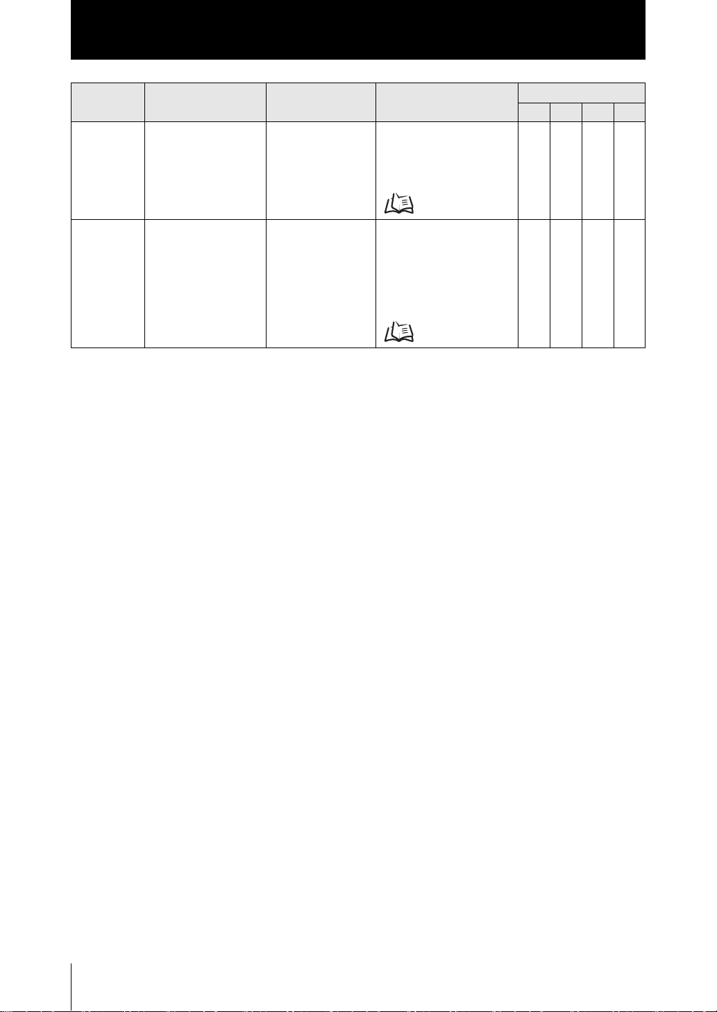
List of Non-procedural Commands
Command
name
CFIMGGET CFIMGGET
Format Returned value Description
(Omitted) Capture the specified
<Group No.>
<Logging No.>
<delimiter>
image data.
For details, refer to
"Capturing Image Data."
HLDC
LDC
No No No
p.36
CFDATGET CFDATGET
<Group No.>
<delimiter>
<measurement value>
<delimiter>
:
<measurement value>
<delimiter>
Obtains the measurement
value from the logging file
for the image data in the
specified group.
For details, refer to
"Capturing Image Data."
No No No
p.36
*1 It is available when USB cable connection is used.
*2 For ZS-DSU Ver 2.00 or later. It is available when USB cable connection is used.
* Specifying CH
In case other than ZS-HLDC
Specify <CH No.> before <delimiter>. If <CH No.> is omitted, the command operates on the CH that received
it.
Example: To acquire the result for TASK2 of the controller of 2CH,
M 1 2 <delimiter>
Support
MDC DSU
Yes
(*2)
Yes
(*2)
In case of ZS-HLDC
Specify #XX at the beginning of the command.
If the CH No. is 1, specify #01. (Be sure to note double digits.)
If <CH No.> is omitted, the command operates on the CH that received it.
Example: To acquire the result for TASK2 of the controller of 2CH,
#02 M 1 <delimiter>
* Specifying the node
Specify @xx at the beginning of the command.
If the node No. is 1, specify @01. (Be sure to note double digits.)
If the node No. is omitted, the command operates on the node that received it.
To specify, the node and CH together in case of ZS-HLDC, specify @XX # △△ at the head of the
command.
* Format of a returned value
A returned value for MEASURE,M,DATAGET,CFLOGGET,CFDATGET is the right aligned 11 characters.
* Upper case and lower case characters
For alphabetic, only upper case characters are accepted.
* Task No.
Omit <Task No.> when issuing a command for ZS-LDC.
Task Nos are assigned as follows: 0: TASK1 1: TASK2 2: TASK3 3: TASK4.
ZS-Series
6
Non-procedural Communication Command Reference

List of Parameters (ZS-LDC)
List of Parameters (ZS-LDC)
The following parameters can be obtained or set by DATASET or DATAGET command:
Unit No. Data No. Parameter Setting range/Output range Others
0 0 Measurement mode 0: STANDARD
1: HI-RESO
2: HI-SPEED
3: HI-SENS
4: CUSTOM
12 Start position of area 1 0 to 639 (pix)
14 End position of area 1 0 to 639 (pix)
24 Start position of area 2 0 to 639 (pix)
26 End position of area 2 0 to 639 (pix)
18 Exposure time 2 to 200 (1 div: 0.1ms) Parameters for CUSTOM
19 Number of additional
lines
20 Line skipping 0: OFF
32 Meas. Cycle 112 to 20000 (us)
1 0 Head installation 0: DIFFUSE
2 0 LD power mode 0: Auto
2 Surface to be
controlled for light
amount
13 Lower limit of LD
power
14 Upper limit of LD
power
37 Incident level
(1st surface)
38 Incident level
(2nd surface)
39 Incident level
(3rd surface)
3 0 Measurement object 0: NORMAL
1 Glass thickness/Gap
mode
2 Glass thickness/Gap
mode
1 to 200
1: ON
1: REGULAR
1: Auto-scale
2: Fixed
0: Peak
1: 1st surface
2: 2nd surface
3: 3rd surface
0 to 800 (1 div: 0.1%)
0 to 800 (1 div: 0.1%)
0 to 4095 (tone)
0 to 4095 (tone)
0 to 4095 (tone)
1: PCB
2: MIRROR
3: GLASS
4: THICK
5: GAP
6: CUSTOM
0: Normal
1: Film/Else
0: STOP
1: MOVE
mode
Non-procedural Communication Command Reference
ZS-Series
7

List of Parameters (ZS-LDC)
Unit No. Data No. Parameter Setting range/Output range Others
3 3 Image smoothing level 0: None
1: Filter size 2
2: Filter size 4
3: Filter size 8
4: Filter size 16
4 Background removing
level before addition
5 Background removing
level after addition
6 Edge threshold 0: 0%
4 0 Mutual interference
prevention mode
1 Mutual interference
prevention timing
5 0 Gain 1 to 5
40 1 Measurement surface
of area 1
32 Measurement value of
area 1 (1st surface)
33 Measurement value of
area 1 (2nd surface)
34 Measurement value of
area 1 (3rd surface)
41 0 Scaling mode 0: OFF
1 Span value -20000 to 20000 (1 div: 0.0001)
2 Offset value
42 2 Smooth 0: OFF
43 2 Average 0: 1 time
0 to 255 (tone)
0 to 4095 (tone)
1: 12.5%
2: 25%
3: 37.5%
4: 50%
5: 62.5%
6: 75%
7: 87.5%
0: OFF
1: ON
0: Timing A
1: Timing B
0: 1st surface
1: 2nd surface
2: 3rd surface
- (nm)
- (nm)
- (nm)
1: ON
-999999999 to 999999999 (nm)
1: ON
1: 2 times
2: 4 times
3: 8 times
4: 16 times
5: 32 times
6: 64 times
7: 128 times
8: 256 times
9: 512 times
10: 1024 times
11: 2048 times
12: 4096 times
Parameters for area 1 at
Glass thickness/Gap
measurement by moving
the objects.
To refer to or set the
parameters for area 2,
add 20 to the unit No. (*)
ZS-Series
8
Non-procedural Communication Command Reference

List of Parameters (ZS-LDC)
Unit No. Data No. Parameter Setting range/Output range Others
44 2 Differential 0: OFF
1: ON
3 Differentiation cycles 1 to 5000 (ms)
45 2 Hold type 0: OFF
1: PEAK
2: BOTTOM
3: P-P
4: AVERAGE
5: SAMPLE
3 Trigger method 0: EXT
1: SELF-UP
2: SELF-DOWN
4 Trigger level -999999999 to 999999999
(nm)
5 Trigger hysteresis 0 to 999999999 (nm)
6 Trigger delay (ms) 0 to 5000 (ms)
7 Sampling period (ms) 1 to 5000 (ms)
8 Trigger delay mode 0: OFF
1: ON
46 5 Offset at zero reset -999999999 to 999999999
(nm)
6 Zero reset mode 0: REAL
1: HOLD
120 0 Non-measurement
settings
1 Output at CLAMP 0: MAX
121 0 Hysteresis width 0 to 999999999 (nm) Setting judgment process
1 Timer mode 0: OFF
2 Delay time 1 to 5000 (ms)
122 2 Monitor focus mode 0: OFF
3 Monitor focus distance
value 1
4 Monitor focus distance
value 2
5 Monitor focus current
value 1
6 Monitor focus current
value 2
7 Monitor focus voltage
value 1
8 Monitor focus voltage
value 2
0: KEEP
1: CLAMP
1: 20mA
2: 12mA
3: 4mA
4: MIN
1: OFF DELAY
2: ON DELAY
3: ONE SHOT
1: ON
-999999999 to 999999999
(nm)
-999999999 to 999999999
(nm)
4 to 20 (mA)
4 to 20 (mA)
-10 to 10 (V)
-10 to 10 (V)
Non-procedural Communication Command Reference
ZS-Series
9

List of Parameters (ZS-LDC)
Unit No. Data No. Parameter Setting range/Output range Others
126 4 External input 0
ActiveSelect
5 External input 1
ActiveSelect
6 External input 2
ActiveSelect
7 External input 3
ActiveSelect
8 External input mode 0: Standard mode
9 Control TASK setting 0: TASK1
127 0 External input (IN) task
mode
1 External input (IN)
function mode
2 External output (OUT)
task mode
4 Linear output task
mode
6 Digital output target 0: OFF
10 External input 0 mode 0: Not used
11 External input 1 mode
12 External input 2 mode
13 External input 3 mode
0: Low Active
1: High Active
1: Bank switching mode
2: Parallel IN off mode
1: TASK2
2: TASK3
3: TASK4
0: None
1: TASK1
2: TASK2
3: TASK3
4: TASK4
5: TASKALL
0: Standard
1: Bank
0: None
1: TASK1
2: TASK2
3: TASK3
4: TASK4
0: None
1: TASK1
2: TASK2
3: TASK3
4: TASK4
1: ON
1: Trigger
2: Hold reset
3: Laser off
4: Zero reset
10
(*)
When [Glass thickness/Gap-Film/Else-Move] is selected, task processes similar to those of ZS-MDC are
performed internally.
The following processes are assigned to respective tasks:
TASK 1 Calculates Area 1 displacement value.
TASK 2 Calculates Area 2 displacement value.
TASK 3 Calculates the difference value (=Thickness/Gap) between TASK1 and TASK2.
TASK 4 Unused
The measurement conditions can be set for each task in this mode.
ZS-Series
Non-procedural Communication Command Reference

List of Parameters (ZS-LDC)
Setting Threshold Value
• A mode other than [Glass thickness/Gap-Film/Else-Move] is selected.
Unit No. Data No. Parameter Setting range/Output range Others
48 2 Lower limit of
threshold
3 Upper limit of
threshold
4 Hysteresis width 0 to 999999999 (nm)
5 Timer mode 0:OFF
6 Delay time 1 to 5000 (ms)
• [Glass thickness/Gap-Film/Else-Move] is selected.
Unit No. Data No. Parameter Setting range/Output range Others
88 2 Lower limit of
threshold
3 Upper limit of
threshold
4 Hysteresis width 0 to 999999999 (nm)
5 Timer mode 0:OFF
6 Delay time 1 to 5000 (ms)
-999999999 to 999999999 (nm)
-999999999 to 999999999 (nm)
1:OFF DELAY
2:ON DELAY
3:ONE SHOT
-999999999 to 999999999 (nm)
-999999999 to 999999999 (nm)
1:OFF DELAY
2:ON DELAY
3:ONE SHOT
Non-procedural Communication Command Reference
ZS-Series
11

List of Parameters (ZS-HLDC)
List of Parameters (ZS-HLDC)
The following parameters can be obtained or set by DATASET or DATAGET command:
Unit No. Data No. Parameter Setting range/Output range Others
0 0 Measurement mode 0: STANDARD
1: HI-RESO
2: HI-SPEED
3: HI-SENS
4: CUSTOM
Measurement mode 1: STANDARD
2: HI-RESO
3: HI-SENS
4: CUSTOM
12 Start position of area 1 0 to 639 (pix)
14 End position of area 1 0 to 639 (pix)
13 Start line of area 1 0 to (No. of additional lines - 1)
15 End line of area 1 0 to (No. of additional lines - 1)
24 Start position of area 2 0 to 639 (pix)
26 End position of area 2 0 to 639 (pix)
25 Start line of area 2 0 to (No. of additional lines - 1)
27 End line of area 2 0 to (No. of additional lines - 1)
18 Exposure time 2 to 200 (1 div: 0.1ms)
When multi-task mode is OFF.
5 to 200 (1 div: 0.1ms)
When multi-task mode is ON.
19 Number of additional
lines
20 Line skipping 0: OFF
22 2-area mode 0: OFF
23 Compensation mode 0: OFF
32 Measurement cycle 112 to 20000 (us)
192 Reference point teach for
compensation mode
193 2-area teach 1: Execute teach
1 0 Head installation 0: Diffuse
2 0 LD power mode 0: Auto
2 Surface to be controlled
for light amount
1 to 200
When multi-task mode is OFF.
8 to 200
When multi-task mode is ON.
1: ON
1: ON
1: Start position compensation
2: End position compensation
3: Start/End position
compensation
1: Execute teach
1: Regular
1: Auto-scale
2: Fixed
0: Peak
1: First surface
2: Second surface
3: Third surface
When multi-task mode
is OFF.
When multi-task mode
is ON.
Parameters for
CUSTOM mode
12
ZS-Series
Non-procedural Communication Command Reference

List of Parameters (ZS-HLDC)
Unit No. Data No. Parameter Setting range/Output range Others
2 6 LD power when fixed 0 to 800 (1 div: 0.1%)
13 Lower limit of LD power 0 to 800 (1 div: 0.1%)
14 Upper limit of LD power 0 to 800 (1 div: 0.1%)
32 Incident level 0 to 4095
36 LD power 0 to 800 (1 div: 0.1%)
37 Incident level
(First surface)
38 Incident level
(Second surface)
39 Incident level
(Third surface)
3 0 Measurement object 0: Normal
2 GLASS/GLASS
THICKNESS mode
3 Image smoothing level 0: No filter
4 Background removing
level before addition
6 Edge threshold 0: 0%
4 0 Mutual interference
prevention mode
1 Mutual interference
prevention timing
5 0 Gain setting 1 to 5
0 to 4095
0 to 4095
0 to 4095
1: PCB
2: Mirror
3: Glass
4: Glass thickness
0: Mode 1
1: Mode 2
1: Filter size 2
2: Filter size 4
3: Filter size 8
4: Filter size 16
0 to 255 (tone)
1: 12.5%
2: 25%
3: 37.5%
4: 50%
5: 62.5%
6: 75%
7: 87.5%
0: OFF
1: ON
0: Timing A
1: Timing B
When the
measurement object is
changed, the settings
are initialized
according to the
selected object.
Non-procedural Communication Command Reference
ZS-Series
13

List of Parameters (ZS-HLDC)
Unit No. Data No. Parameter Setting range/Output range Others
40 0 Measurement mode 0: OFF
1: Average
2: Peak
3: Bottom
4: Thickness
5: Gap
6: K+mX; +nY
3 Parameter X 0: None
1: TASK 1
2: TASK 2
3: TASK 3
4: TASK 4
4 Parameter Y 0: None
1: TASK 1
2: TASK 2
3: TASK 3
4: TASK 4
5 Parameter K -999999999 to 999999999 (nm)
8 Parameter M -100 to 100 (1div: 0.1)
9 Parameter N -100 to 100 (1div: 0.1)
1 Surface for
measurement (Area 1)
10 Surface for
measurement (Area 2)
11 Measurement position 1
(for thickness
measurement)
12 Measurement position 2
(for thickness
measurement)
13 Measurement area 0: Area 1
14 Width of peak bottom 0 to 255
32 Measurement value
(First surface)
33 Measurement value
(Second surface)
34 Measurement value
(Third surface)
41 0 Scaling mode 0: OFF
1 Span value -20000 to 20000 (1 div: 0.0001)
2 Offset value
42 2 Smooth 0: OFF
0: First surface
1: Second surface
2: Third surface
0: First surface
1: Second surface
2: Third surface
0: None
1: Average
2: Peak
3: Bottom
0: None
1: Average
2: Peak
3: Bottom
1: Area 2
- (nm)
- (nm)
- (nm)
1: ON
-999999999 to 999999999 (nm)
1: ON
TASK1 settings.
The settings in Unit
Number 40 are valid
only for multi-task
mode.
14
ZS-Series
Non-procedural Communication Command Reference

List of Parameters (ZS-HLDC)
Unit No. Data No. Parameter Setting range/Output range Others
43 2 Average 0: 1 time
1: 2 times
2: 4 times
3: 8 times
4: 16 times
5: 32 times
6: 64 times
7: 128 times
8: 256 times
9: 512 times
10: 1024 times
11: 2048 times
12: 4096 times
44 2 Differential type 0: OFF
1: ON
3 Differentiation cycles 1 to 5000 (ms)
45 2 Hold type 0: Through
1: Peak
2: Bottom
3: Peak to peak
4: Average
5: Sampling
3 Trigger method 0: External input
1: Self up
2: Self down
4 Trigger level -999999999 to 999999999 (nm)
5 Trigger hysteresis 0 to 999999999 (nm)
6 Trigger delay (ms) 0 to 5000 (ms)
7 Sampling period (ms) 1 to 5000 (ms)
8 Trigger delay mode 0: OFF
1: ON
46 5 Offset at zero reset -999999999 to 999999999 (nm)
7 Zero reset mode 0: REAL
1: HOLD
64 Status 0: OFF
1: ON
TASK1 settings.
The settings in Unit
Number 40 are valid
only for multi-task
mode.
(*)
If GLASS/MODE 2 or GLASS THICKNESS/MODE 2 is selected, a process using multiple tasks will be
performed, as in the multi-task mode.
The following processes are assigned to the respective tasks:
TASK 1 Calculates Area 1 displacement value.
TASK 2 Calculates Area 2 displacement value.
TASK 3 GLASS: Calculates the result of the NEAR side of TASK 1 and TASK 2.
GLASS THICKNESS: Calculates the difference value between TASK1 and TASK2.
TASK 4 Unused
ZS-Series
Non-procedural Communication Command Reference
15

List of Parameters (ZS-HLDC)
The measurement conditions can be set for each task in this mode.
• Configuration of Task
The ZS-HLDC performs task processing.
The processing units for each task are grouped into 20 units.
To refer to the processing unit of TASK N, therefore, add 20×(N-1) to the above processing unit No.
Example: To change the averaging process of TASK2, refer to or set to a parameter with:
Process unit No.=43+20×(2-1)=63 and
Data No.=2
Unit No. Data No. Parameter Setting range/Output range Others
120 0 Hysteresis width 0 to 999999999 (nm) Setting judgment process
1
2
3 Judgment output
121 0 Non-measurement
122 2 Monitor focus mode 0: OFF
3 Monitor focus distance
4 Monitor focus distance
5 Monitor focus current
6 Monitor focus current
7 Monitor focus voltage
8 Monitor focus voltage
21 Output mode TASK When multi-task mode is OFF.
Timer mode 0: OFF
1: OFF-Delay
2: ON-Delay
3: One shot
Delay time 1 to 5000 (ms)
0: TASK 1
TASK
settings
value 1
value 2
value 1
value 2
value 1
value 2
1: TASK 2
2: TASK 3
3: TASK 4
0: Keep
1: Clamp
1: ON
-999999999 to 999999999 (nm)
-999999999 to 999999999 (nm)
4 to 20 (mA)
4 to 20 (mA)
-10 to 10 (V)
-10 to 10 (V)
0: OFF
1: ON
When multi-task mode is ON.
0: OFF
1: TASK 1
2: TASK 2
3: TASK 3
16
ZS-Series
Non-procedural Communication Command Reference

List of Parameters (ZS-HLDC)
Unit No. Data No. Parameter Setting range/Output range Others
122 23 Output at CLAMP Voltage output
0: MAX
1: 10 V
2: 9 V
3: 8 V
4: 7 V
5: 6 V
6: 5 V
7: 4 V
8: 3 V
9: 2 V
10: 1 V
11: 0 V
12: -1 V
13: -2 V
14: -3 V
15: -4 V
16: -5 V
17: -6 V
18: -7 V
19: -8 V
20: -9 V
21: -10 V
22: MIN
Current output
0: MAX
1: 20 mA
2: 19 mA
3: 18 mA
4: 17 mA
5: 16 mA
6: 15 mA
7: 14 mA
8: 13 mA
9: 12 mA
10: 11 mA
11: 10 mA
12: 9 mA
13: 8 mA
14: 7 mA
15: 6 mA
16: 5 mA
17: 4 mA
123
Digital output
2 Monitor focus mode 0: OFF
1: ON
3
4
5
6
7 Clear monitor focus 1: Clear
Monitor focus distance
value 1
Monitor focus distance
value 2
Monitor focus current
value 1
Monitor focus current
value 2
-999999999 to 999999999 (nm)
-999999999 to 999999999 (nm)
0 to 65535
0 to 65535
Non-procedural Communication Command Reference
ZS-Series
17

List of Parameters (ZS-HLDC)
Unit No. Data No. Parameter Setting range/Output range Others
123 8 Output at CLAMP 0 to 65535
124
Logging
126
Link
240
Parallel input
10 Output TASK
(When the
measurement value is
output)
11 Output mode 0: OFF
12 Update cycle 0 to 100
2Mode 0: OFF
3 Buffering period 1 to 65535
4 Buffer size per item of
data
14 TASK 1 0: OFF
15 TASK 2 0: OFF
16 TASK 3 0: OFF
17 TASK 4 0: OFF
0 Output TASK 0: TASK 1
6Mode 0: OFF
4 Input 0 0: Low Active
5 Input 1
6 Input 2
7 Input 3
8 External input mode 0: Normal mode
9 Control TASK setting 0: TASK1
0: TASK 1
1: TASK 2
2: TASK 3
3: TASK 4
4: Consecutively
1: Measurement value
2: Judgment
1: ON
1 to 1000
1: ON
1: ON
1: ON
1: ON
1: TASK 2
2: TASK 3
3: TASK 4
1: ON
1: High Active
1: Bank switching mode
2: Parallel IN off mode
1: TASK2
2: TASK3
3: TASK4
When multi-task mode is
ON.
18
ZS-Series
Non-procedural Communication Command Reference

List of Parameters (ZS-HLDC)
Setting Threshold Value
When multi-task mode is OFF
• When selecting a mode other than "GLASS/MODE 2" and "GLASS THICKNESS/
MODE 2".
Unit No. Data No. Parameter Setting range/Output range Others
48 2 Lower limit of
threshold
3 Upper limit of
threshold
4 Hysteresis width 0 to 999999999 (nm)
5 Timer mode 0:OFF
6 Delay time 1 to 5000 (ms)
• When selecting "GLASS/MODE 2" or "GLASS THICKNESS/MODE 2" mode.
Unit No. Data No. Parameter Setting range/Output range Others
88 2 Lower limit of
threshold
3 Upper limit of
threshold
4 Hysteresis width 0 to 999999999 (nm)
5 Timer mode 0:OFF
6 Delay time 1 to 5000 (ms)
-999999999 to 999999999 (nm)
-999999999 to 999999999 (nm)
1:OFF DELAY
2:ON DELAY
3:ONE SHOT
-999999999 to 999999999 (nm)
-999999999 to 999999999 (nm)
1:OFF DELAY
2:ON DELAY
3:ONE SHOT
When multi-task mode is ON
• Can be set for each TASK.
Unit No. Data No. Parameter Setting range/Output range Others
48 2 Lower limit of
threshold
3 Upper limit of
threshold
4 Hysteresis width 0 to 999999999 (nm)
5 Timer mode 0:OFF
6 Delay time 1 to 5000 (ms)
-999999999 to 999999999 (nm)
-999999999 to 999999999 (nm)
1:OFF DELAY
2:ON DELAY
3:ONE SHOT
Non-procedural Communication Command Reference
TASK1 settings.
For TASK2 to
TASK4, the unit
numbers are as
follows:
TASK2: 68
TASK3: 88
TASK4: 108
ZS-Series
19

List of Parameters (ZS-MDC)
List of Parameters (ZS-MDC)
The following parameters can be acquired or set by DATASET or DATAGET command:
Unit No. Data No. Parameter Setting range/Output range Others
0 0 Destination CH to
input data A
1 Destination CH to
input data B
2 Destination CH to
input data C
3 Destination CH to
input data D
4 Destination CH to
input data E
5 Destination CH to
input data F
6 Destination CH to
input data G
7 Destination CH to
input data H
8 Destination CH to
input data I
9 Input mode of data A 0: OFF 1: ON
10 Input mode of data B 0: OFF 1: ON
11 Input mode of data C 0: OFF 1: ON
12 Input mode of data D 0: OFF 1: ON
13 Input mode of data E 0: OFF 1: ON
14 Input mode of data F 0: OFF 1: ON
15 Input mode of data G 0: OFF 1: ON
16 Input mode of data H 0: OFF 1: ON
17 Input mode of data I 0: OFF 1: ON
32 Acquisition result A
33 Acquisition result B
34 Acquisition result C
35 Acquisition result D
36 Acquisition result E
37 Acquisition result F
38 Acquisition result G
39 Acquisition result H
40 Acquisition result I
40 0 Data setting mode 0: OFF
0 to 11 (CH)
0 to 11 (CH)
0 to 11 (CH)
0 to 11 (CH)
0 to 11 (CH)
0 to 11 (CH)
0 to 11 (CH)
0 to 11 (CH)
0 to 11 (CH)
-999999999 to 999999999 (nm)
-999999999 to 999999999 (nm)
-999999999 to 999999999 (nm)
-999999999 to 999999999 (nm)
-999999999 to 999999999 (nm)
-999999999 to 999999999 (nm)
-999999999 to 999999999 (nm)
-999999999 to 999999999 (nm)
-999999999 to 999999999 (nm)
1: Individual
2: Calculation
20
ZS-Series
Non-procedural Communication Command Reference

List of Parameters (ZS-MDC)
Unit No. Data No. Parameter Setting range/Output range Others
40 1 Individual setting
mode
2 Calculation setting
mode
3 Parameter X 0: Input A
4 Parameter Y
5 Parameter K
6 Parameter m -100 to 100 (×0.1)
7 Parameter n -100 to 100 (×0.1)
8 Input A setting
(AVE,MAX-MIN)
9 Input B setting
(AVE,MAX-MIN)
10 Input C setting
(AVE,MAX-MIN)
11 Input D setting
(AVE,MAX-MIN)
12 Input E setting
(AVE,MAX-MIN)
13 Input F setting
(AVE,MAX-MIN)
14 Input G setting
(AVE,MAX-MIN)
15 Input H setting
(AVE,MAX-MIN)
16 Input I setting
(AVE,MAX-MIN)
17 TASK1 setting
(AVE,MAX-MIN)
0: Input A
1: Input B
2: Input C
3: Input D
4: Input E
5: Input F
6: Input G
7: Input H
8: Input I
0: Thickness (K-(X+Y))
1: Step (X-Y)
2: K+mX+nY
3: AVE
4: MAX-MIN
1: Input B
2: Input C
3: Input D
4: Input E
5: Input F
6: Input G
7: Input H
8: Input I
9: TASK 1
10: TASK 2
11: TASK 3
12: TASK 4
-999999999 to 999999999 (nm)
0: OFF
1: ON
Non-procedural Communication Command Reference
ZS-Series
21

List of Parameters (ZS-MDC)
Unit No. Data No. Parameter Setting range/Output range Others
40 18 TASK2 setting
(AVE,MAX-MIN)
19 TASK3 setting
(AVE,MAX-MIN)
20 TASK4 setting
(AVE,MAX-MIN)
21 Thickness
41 0 Scaling mode 0: OFF
1 Span value -20000 to 20000 (×0.0001)
2 Offset value
42 2 Smooth 0: OFF
43 2 Average 0: 1 time
44 2 Differential 0: OFF
3 Differentiation cycles 1 to 5000 (ms)
45 2 Hold type 0: OFF
3 Trigger method 0: EXT
4 Trigger level
5 Trigger hysteresis 0 to 999999999 (nm)
6 Trigger delay (ms) 0 to 5000 (ms)
7 Sampling period (ms) 1 to 5000 (ms)
8 Trigger delay mode 0: OFF
46 5 Offset at zero reset
6 Zero reset mode 0: REAL
0: OFF
1: ON
-999999999 to 999999999 (nm)
1: ON
-999999999 to 999999999 (nm)
1: ON
1: 2 times
2: 4 times
3: 8 times
4: 16 times
5: 32 times
6: 64 times
7: 128 times
8: 256 times
9: 512 times
10: 1024 times
11: 2048 times
12: 4096 times
1: ON
1: PEAK
2: BOTTOM
3: P-P
4: AVERAGE
5: SAMPLE
1: SELF-UP
2: SELF-DOWN
-999999999 to 999999999 (nm)
1: ON
-999999999 to 999999999 (nm)
1: HOLD
22
ZS-Series
Non-procedural Communication Command Reference

List of Parameters (ZS-MDC)
Unit No. Data No. Parameter Setting range/Output range Others
120 0 Non-measurement
settings
1 Output at CLAMP 0: MAX
121 0 Hysteresis width 0 to 999999999 (nm)
1 Timer mode 0: OFF
2 Delay time 1 to 5000 (ms)
122 2 Monitor focus mode 0: OFF
3 Monitor focus
distance value 1
4 Monitor focus
distance value 2
5 Monitor focus current
value 1
6 Monitor focus current
value 2
7 Monitor focus voltage
value 1
8 Monitor focus voltage
value 2
125 4 External input 0
ActiveSelect
5 External input 1
ActiveSelect
6 External input 2
ActiveSelect
7 External input 3
ActiveSelect
8 External input mode 0: Standard mode
9 Control TASK setting 0: TASK1
126 0 External input (IN)
task mode
1 External input (IN)
function mode
0: KEEP
1: CLAMP
1: OFF DELAY
2: ON DELAY
3: ONE SHOT
1: ON
-999999999 to 999999999 (nm)
-999999999 to 999999999 (nm)
4 to 20 (mA)
4 to 20 (mA)
-10 to 10 (V)
-10 to 10 (V)
0: Low Active
1: High Active
1: Bank switching mode
2: ParallelIN off mode
1: TASK2
2: TASK3
3: TASK4
0: None
1: TASK1
2: TASK2
3: TASK3
4: TASK4
5: TASKALL
0: Standard
1: Bank
Non-procedural Communication Command Reference
ZS-Series
23

List of Parameters (ZS-MDC)
Unit No. Data No. Parameter Setting range/Output range Others
126 2 External output (OUT)
task mode
4 Linear output task
mode
6 Digital output target 0: OFF
10 External input 0 mode 0: Not used
11 External input 1 mode
12 External input 2 mode
13 External input 3 mode
0: None
1: TASK1
2: TASK2
3: TASK3
4: TASK4
0: None
1: TASK1
2: TASK2
3: TASK3
4: TASK4
1: ON
1: Trigger
2: Hold reset
3: Laser off
4: Zero reset
• Configuration of Task
The ZS-MDC performs task processing. The processing units for each task are grouped
into 20 units. To refer to the processing unit of TASK N, therefore, add 20×(N-1) to the
above processing unit No.
Example: To change the averaging process of TASK2, refer to or set to a parameter with:
Process unit No.=43+20×(2-1)=63 and
Data No.=2
Setting Threshold Value
• In case of TASK1
Unit No. Data No. Parameter Setting range/Output range Others
48 2 Lower limit of
threshold
3 Upper limit of
threshold
4 Hysteresis width 0 to 999999999 (nm)
5 Timer mode 0: OFF
6 Delay time 1 to 5000 (ms)
To change the threshold of TASKN, change the unit No. as follows:
Unit No.=48+20X(N-1)
-999999999 to 999999999 (nm)
-999999999 to 999999999 (nm)
1: OFF DELAY
2: ON DELAY
3: ONE SHOT
24
ZS-Series
Non-procedural Communication Command Reference

List of Parameters (ZS-DSU)
List of Parameters (ZS-DSU)
The following parameters can be obtained or set by DATASET or DATAGET command:
Unit No. Data No. Parameter Setting range/Output range Others
0 0 Input CH to Source A 0: 1CH
1 Input CH to Source B
2 Input CH of Source C
3 Input CH to Source D
4 Input CH to Source E
5 Input CH to Source F
6 Input CH to Source G
7 Input CH to Source H
8 Input CH of Source I
9 Input CH of Source J
10 Input CH of Source K
11 Input CH of Source L
12 Input CH of Source M
13 Input CH of Source N
14 Selected TASK of Source A0: TASK1
15 Selected TASK of Source
B
16 Selected TASK of Source
C
17 Selected TASK of Source
D
18 Selected TASK of Source
E
19 Selected TASK of Source
F
20 Selected TASK of Source
G
21 Selected TASK of Source
H
22 Selected TASK of Source
I
23 Selected TASK of Source
J
24 Selected TASK of Source
K
25 Selected TASK of Source
L
26 Selected TASK of Source
M
27 Selected TASK of Source
N
1: 2CH
2: 3CH
3: 4CH
4: 5CH
5: 6CH
6: 7CH
7: 8CH
8: 9CH
9: 10CH
:
13: 14CH
1: TASK2
2: TASK3
3: TASK4
4: InputA
5: InputB
:
13: InputI
Valid when the
connected controller
is a ZS-MDC.
Non-procedural Communication Command Reference
ZS-Series
25

List of Parameters (ZS-DSU)
Unit No. Data No. Parameter Setting range/Output range Others
0 28 Save mode of Source A 0: OFF
29 Save mode of Source B
30 Save mode of Source C
31 Save mode of Source D
32 Save mode of Source E
33 Save mode of Source F
34 Save mode of Source G
35 Save mode of Source H
36 Save mode of Source I
37 Save mode of Source J
38 Save mode of Source K 0: OFF
39 Save mode of Source L
40 Save mode of Source M
41 Save mode of Source N
64 Acquisition result A
65 Acquisition result B
66 Acquisition result C
67 Acquisition result D
68 Acquisition result E
69 Acquisition result F
70 Acquisition result G
71 Acquisition result H
72 Acquisition result I
73 Acquisition result J
74 Acquisition result K
75 Acquisition result L
76 Acquisition result M
77 Acquisition result N
1 0 Start trigger mode 0: None
1 Start trigger
Trigger edge polarity
2 Start trigger
Data selection
3 Start trigger
Delay
4 Start trigger
Data threshold
1: ON
1: ON
-999999999 to 999999999 (nm)
1: External input
2: Data
3: Window
4: I/O
5: HOUR
0: Up trigger
1: Down trigger
0: Source A
1: Source B
:
13: Source N
-9999 to 9999 (ms) (*1)
-127 through 127 (Number of
images) (*2)
-999999999 to 999999999 (nm)
(*1) [Save image] is
set to OFF.
(*2) [Save image] is
set to ON.
26
ZS-Series
Non-procedural Communication Command Reference

List of Parameters (ZS-DSU)
Unit No. Data No. Parameter Setting range/Output range Others
1 6 Start trigger
Window mode
7 Start trigger
Window upper limit
8 Start trigger
Window upper limit
10 Start trigger
Pattern of I/O
I/O selection
12 End trigger mode 0: BUTTON
13 End trigger
Trigger edge polarity
14 End trigger
Data selection
15 End trigger
Data threshold
17 End trigger
Window mode
18 End trigger
Window upper limit
19 End trigger
Window lower limit
21 End trigger
Pattern of I/O
I/O selection
24 End trigger
Logging data points
2 0 Save mode 0: OneShot
1 Repeat mode 0: New
2 Repeat end conditions 0: None
0: WindowIn
1: WindowOut
-999999999 to 999999999 (nm)
-999999999 to 999999999 (nm)
0: IN0
1: IN1
2: IN2
3: IN3
4: OUT0
5: OUT1
6: OUT2
7: OUT3
8: OUT4
1: EXT
2: DATA
3: WINDOW
4: I/O
5: HOUR
6: QUANT
7: TIME
Same as Start trigger
Same as Start trigger
1 through 999999 (*1)
1 through 128 (*2)
1: Repeat
1: ADD
2: OVER WR
1: Trigger times
2: Elapsed time (timeout)
When [Save image] is
set to ON, [TIME] is
not available.
(*1) [Save image] is
set to OFF.
(*2) [Save image] is
set to ON.
When [Save image] is
set to ON, [REPEAT]
is not available.
When [Save image] is
set to ON, [ADD] is
not available.
Non-procedural Communication Command Reference
ZS-Series
27

List of Parameters (ZS-DSU)
Unit No. Data No. Parameter Setting range/Output range Others
2 3 Repeat end conditions
Trigger times
6 Interval of saving image 0: All
7 NG save mode 0: OR
8 Save image mode 0: Standard
3 1 I/O data 0: No save
2 Save direction (Range) 0: COLUMN
3 New line input 0: Ignore
Label input and time settings can not be set or referenced.
1 to 100000 (pcs)
1: Save NG
1: AND
1: Latest
1: Save
1: ROW
1: Enable
It is available only if
[Save image] is set to
ON.
28
ZS-Series
Non-procedural Communication Command Reference

List of Parameters (ZS-DSU)
Judgment relation
Unit No. Data No. Parameter Setting range/Output range Others
40 0 Input source 0: Source A
1: Source B
2: Source C
3: Source D
4: Source E
5: Source F
6: Source G
7: Source H
8: Source I
9: Source J
10: Source K
11: Source L
12: Source M
13: Source N
1 Lower limit of
threshold
2 Upper limit of
threshold
-999999999 to 999999999 (nm)
-999999999 to 999999999 (nm)
For Image Logging
Unit No. Data No. Parameter Setting range/Output range Others
20 0 Align image 0: None
1: 1CH
2: 2CH
:
14: 14CH
1 Save image 0: OFF
1: ON
Non-procedural Communication Command Reference
ZS-Series
29

FLOWDATA Reference
C
FLOWDATA Reference
What is FLOWDATA?
The ZS series implements high speed sampling measurement up to 110us.
Handling these measurement data with an external device requires reading in a large
amount of data.
The ZS series are provided with a mechanism which enables to handle and acquire
measurement data by a given bundle.
This bundle of data is called a FLOWDATA.
■ How to acquire FLOWDATA
FLOWDATA is batch output if the controller has accepted the command for acquiring a
FLOWDATA when data is accumulated for the specified buffer size (max. 1000 data).
A device receiving data (such as PC) needs to issue the command before the ZS controller accumulates measurement data for the buffer size.
LD ONZEROENABLE
H
P
L
P
Issue command
Batch acquire data for the buffer size
Receive data
Issue command
Batch acquire data for the buffer size
Receive data
Issue command
Batch acquire data for the buffer size
Receive data
Issue command
If the controller has not received the command when measurement data for the buffer size is
accumulated in the controller, the past data is overwritten:
In this case, it raises an error flag for buffer overflow. A device receiving data (such as PC) needs
to check this flag to see if the commands have been issued in time.
Controller
Accumulating data
Output the result
Accumulating data
Output the result
Accumulating data
Output the result
Accumulating data
ZS-Series
30
Non-procedural Communication Command Reference

FLOWDATA Reference
Format
After outputting the command for acquiring FLOWDATA, the binary data is output in the
following format:
Header division (4bytes) Data division (4bytes)
Configuration of FLOWDATA p.34
Binary data is used for response data of FLOWDATA to give the highest priority to the speed. Therefore,
general purpose communication tools such as HyperTerminal may not be used to receive the data.
■ Buffer size and buffer intervals
The buffer size of measurement data to be accumulated in the ZS controller and its
buffer intervals can be changed.
Change the following parameters:
* DATAGET and DATASET commands are used to change and refer to the parameters.
Unit No. Data No. Parameter Description
124 2 FLOWDATA accumulation
mode
3 Buffer intervals 1 to 65535 (pcs)
4 Buffer size 1 to 1000 (pcs)
0: OFF
1: ON
■ Logging data
Data to be accumulated in the ZS controller can be selected.
●In case of ZS-LDC
A maximum of 3 data can be accumulated.
Unit No. Data No. Parameter Description
124 5 Accumulated data 1 *
6 Accumulated data 2
7 Accumulated data 3
* A setting value changes in accordance with the measurement mode.
•[Glass thickness/Gap-Film/Else-Move] is selected.
Val ue Description
0 No accumulation
1 Result for area 1
2 Result for area 2
3 Thickness/Gap value
Non-procedural Communication Command Reference
ZS-Series
31

FLOWDATA Reference
•Glass thickness/Gap except for the above is selected.
Val ue Description
0 No accumulation
1 Thickness/Gap value
•A mode other than above is selected.
Val ue Description
0 No accumulation
1 Distance value (Measurement value)
●In case of ZS-HLDC
• When multi-task mode is OFF
• When GLASS/MODE 2 or GLASS THICKNESSS/MODE 2 is selected for the measurement object
Unit No. Data No. Value Description
124 5 0 No accumulation
1 Accumulation of result of area 1
2 Accumulation of result of area 2
3 Accumulation of result of glass surface or
glass thickness
• When a mode other than the above is selected for the measurement object
Unit No. Data No. Value Description
124 5 0 No accumulation
1 Accumulation
• When multi-task mode is ON
Unit No. Data No. Value Description
124 14 0 Does not accumulate the result of TASK 1
1 Accumulate the result of TASK 1
15 0 Does not accumulate the result of TASK 2
1 Accumulate the result of TASK 2
16 0 Does not accumulate the result of TASK 3
1 Accumulate the result of TASK 3
17 0 Does not accumulate the result of TASK 4
1 Accumulate the result of TASK 4
32
ZS-Series
Non-procedural Communication Command Reference

●In case of ZS-MDC
A maximum of 9 data can be accumulated.
Unit No. Data No. Parameter Description
124 5 Accumulated data 1 0: No accumulation
6 Accumulated data 2
7 Accumulated data 3
8 Accumulated data 4
9 Accumulated data 5
10 Accumulated data 6
11 Accumulated data 7
12 Accumulated data 8
13 Accumulated data 9
Increasing data to be accumulated extends the measurement cycle of the ZS controller. Confirm it
by selecting [SYSTEM]-[INFO]-[CYCLE] after setting.
1: Measurement result of TASK 1
2: Measurement result of TASK 2
3: Measurement result of TASK 3
4: Measurement result of TASK 4
5: Measurement result of Input A
6: Measurement result of Input B
7: Measurement result of Input C
8: Measurement result of Input D
9: Measurement result of Input E
10: Measurement result of Input F
11: Measurement result of Input G
12: Measurement result of Input H
13: Measurement result of Input I
FLOWDATA Reference
Non-procedural Communication Command Reference
ZS-Series
33

FLOWDATA Reference
Configuration of FLOWDATA Response
1 packet of FLAWDATA
Header division
1st byte 2nd byte 3rd byte 4th byte –
ABCDEFGHIJKLData
8 11245121115 32
Details of header division
Data Name Description
A Unused Reserved bit
B FLOWDATA overflow bit Normally set to 0.Set to 1 when there is an overflow in
FLOWDATA accumulation.
C Decimal information Normally set to 0.0: nm order, 1: µm order
D TASK No. TASK1 to TASK4 (*1)
E CH No. CH No. of data source
F Unit states (Input) Indicates ON/OFF states of various input lines. (*2)
G FLOWDATA stop bit • All data are set to 1 if FLOWDATA does not flow over subse-
quently. (Always set to 1 for one-shot requests)
• All data are set to 0 if FLOWDATA continues to flow over.
(Until FLOWDATA is stopped after requested (in succession)
H TASK judgment result bit
I Disabled Reserved bit
J
K
L Unit states (Output) Indicates output states (states of measurement results). (*4)
Data Measurement data Signed 32 bit data
Indicates the TASK judgment result of data source. (*3)
When the decimal info division is 0, the unit of the data is nm.
When the decimal info division is 1, the unit of the data is µm
Data
division
Meaning of
data
Number of
bits
=Total
64 bits
34
*1 TASK No.=bit data+1
Example: bit data=10B=2 (dec)
indicates TASK3 data.
*2 The input lines are, from the lower bit, assigned to:
In case of ZS
• Input terminal 4 (Unused. Always set to 0.)
• Input terminal 3
• Input terminal 2
• Input terminal 1
• Input terminal 0 (5 inputs in total.)
ZS-Series
Non-procedural Communication Command Reference

FLOWDATA Reference
*3 Data to be received and their states are as follows:
00b=Not executed
01b=LOW
10b=PASS
11b=HIGH
*4 The output states are, from the lower bit, assigned to:
In case of ZS
• Output terminal 4 (Busy output)
• Output terminal 3 (Enable output)
• Output terminal 2 (Low output)
• Output terminal 1 (Pass output)
• Output terminal 0 (High output)
(5 outputs in total). States in parenthesis indicate the standard states.
[FLOWDATA setting example]
DATASET 124 2 1
DATASET 124 3 1
DATASET 124 4 1
DATASET 0 0 1
DATASET 0 1 2
DATASET 0 2 3
DATASET 0 3 4
DATASET 124 5 5
DATASET 124 6 6
DATASET 124 7 7
DATASET 124 8 8
DATASAVE
FLOWDATA
FLOWDATA accumulation mode ON
1 buffer interval
1 buffer size
Input A is 1 CH.
Input B is 2 CH.
Input C is 3 CH.
Input D is 4 CH.
Accumulate data 1 is Input A.
Accumulate data 2 is Input B.
Accumulate data 3 is Input C.
Accumulate data 4 is Input D.
Data save
ABCDEFGHIJKL
FF81010642724D0A
1 㸢䇭172847682111111110000001000000010000011001000010011100100100110100001010
FF8201065A74F103
1 㸢䇭66155610111111110000010000000010000011001011010011101001111000100000011
FF830312FF837405
1 㸢䇭91522047111111110000011000000110001001011111111100000110111010000000101
FF84031240118B05
1 㸢䇭92000000111111110000100000000110001001001000000000100011000101100000101
Indicates the unit status (states of
measurement results).
From the lower bit
Output terminal 4 BUSY
Output terminal 3 ENABLE
Output terminal 2 LOW
Output terminal 1 PASS
Output terminal 0 HIGH
Disabled
TASK judgment result bit
00b= Not executed
01b= LOW
10b= PASS
11b= HIGH
FlowData stop bit
Unit status: Indicates ON/OFF states of
various input lines.
From lower bit
Input terminal 4 (Unused, Always 0)
Input terminal 3
Input terminal 2
Input terminal 1
Input terminal 0
CH No.
TASK No.
Decimal information
Normally set to 0: nm order, 1: µm order
FlowData overflow bit
Normally set to 0. Set to 1 when there is an
overflow in FLOWDATA accumulation.
Unused
Non-procedural Communication Command Reference
ZS-Series
35

Capturing Image Data
Capturing Image Data
For ZS-DSU (Ver 2.000 or later), image data logging from ZFV is available. Image data on
the memory card can be shown as image files (.bmp) by inserting the memory card into
the memory slot on the personal computer. Image data can also be imported from the
memory card inserted into the ZS-DSU by entering the command below.
Command name Format
CFIMGGET CFIMGGET <Group No.> <Logging No.> <delimiter>
* Group No. is the logging group number that is assigned for each logging trigger.
* Logging No. is the serial number (logging number) that is assigned during one logging process.
* Receiving of the image data is performed through the XMODEM communication. (Refer to the next topic.)
* For you reference: Folder tree in the memory card
Top OMRON LOG Date 1 Log000.log
Log001.log
Date 2 Log002.log
↓Group No.
IMG Date 000 Log.log
OK 000_***.bmp
Folder
NG 002_***.bmp
File
↓Logging No.
001_***.bmp
↓Group No.
001 Log.log
OK 000_***.bmp
NG 001_***.bmp
Example:
To read image data with (*) mark, enter the following command.
CFIMGGET 001 002<delimiter>
001 is Group No.
002 is Logging No.
* Numbers must be entered in the 3-digit format.
* Specifying OK/NG folders is not necessary.
Measurement result for the logged image data can also be obtained. Measurement result is stored in the log
file in the same group folder. To get the measurement result to the personal computer, enter the following
command.
Command name Format
CFDATGET CFDATGET <Group No.> <delimiter>
↓Logging No.
002_***.bmp (*)
36
ZS-Series
Non-procedural Communication Command Reference

Capturing Image Data
●Flow of XMODEM communication
When you capture image data by entering this command, image data are obtained
through XMODEM communication. Communication flow is as follows:
Host device (personal computer)
Switch XMODEM
Request to receiving
* 1 packet = 128 bytes
(Check by CRC)
Data are successfully received.
* Returns "NAK" if receiving error
has been occurred.
Data are successfully received.
Data are successfully received.
CFIMGGET command
"READY" reply
NAK (a)
128-byte data (BK No. 1)
ACK
128-byte data (BK No. 2)
ACK
128-byte data (BK No. *)
ACK
EOT
ZS-DSU
Switch XMODEM
Start the reply to the request
(Send BK No. 1)
* No reply when "C" is sending.
(Send BK No. 2)
(Send BK No. *)
All data has been completely sent
XMODEM abort ACK
OK
Completed.
ZS-Series
Non-procedural Communication Command Reference
37

Example of Usage
Example of Usage
To give an example, provided below is a procedure to communicate by non-procedural
commands using Windows standard tool HyperTerminal.
1. Start up HyperTerminal.
HyperTerminal is located under [Program]-[Accessory]-[Communication].
(1) Enter an appropriate project name.
(2) Select the COM port connected to the ZS in the Connection Method section.
(3) Set the communication conditions.
38
ZS-Series
Non-procedural Communication Command Reference

Example of Usage
(4) HyperTerminal is started up.
2. To make the interaction with commands easier, set echo and other
functions.
(1) Open [Property].
(2) Select the setting tag, and then ASCII settings.
Non-procedural Communication Command Reference
ZS-Series
39

Example of Usage
(3) Check the following items, and press OK to complete the setting.
3. Set the communication conditions for the ZS side.
(1) Set [System]-[Communication]-[RS-232C] as consistent with the above setting.
(2) Set [System]-[Communication]-[Protocol] as non-procedural.
4. Change ZS into "RUN" mode.
5. Perform non-procedural communication.
(1) Input a command, and then press the return key.
40
ZS-Series
Non-procedural Communication Command Reference

Example of Usage
(2) A returned value responding to the command is returned from the controller.
Non-procedural Communication Command Reference
ZS-Series
41

Revision History
Revision History
Revision
Symbol
A October 2004 First edition
B June 2005 • Commands and parameters compatible with ZS-DSU (v2.000) are added.
C October 2005 • Commands and parameters compatible with ZS-HLDC is added.
Revision Date Description
• Multiple controllers connection with ZFV is added.
42
ZS-Series
Non-procedural Communication Command Reference
 Loading...