

OMRON ZR-RX40 User Manual

Portable Multi Logger
ZR-RX40
User's Manual
Cat. No. Z260-E1-02

Introduction
This manual provides information regarding functions, performance and operating methods that are
required for using the ZR-RX40.
When using the ZR-RX40, be sure to observe the following:
・The ZR-RX40 must be operated by personnel knowledgeable in electrical engineering.
・To ensure correct use, please read this manual thoroughly to deepen your understanding of the product.
・Please keep this manual in a safe place so that it can be referred to whenever necessary.
Registered Trademarks
・Microsoft and Windows are either registered trademarks or trademarks of Microsoft Corp. in the
United States and/or other countries.
・Other product and company names herein may be either registered trademarks or trademarks
of their respective owners.
Type of Manuals
The manuals of the ZR-RX40 series consist of the following.
Select the manual suitable for your purpose and read it before starting operation.
Manual packaged in the product (brochure)
Portable Multi Logger
ZR-RX40
Start Up Guide
Cat. No. Z259-E1-01
Start Up Guide
The basic information to use the ZR-RX40 series is described,
such as the information for safe and correct use, confirmation
of the package, procedure from connection to measurement,
and the information of functions and specifications of the ZR-RX40
series.
Manuals contained in the utility CD-ROM (pdf data)
Software Manual
・How to install PC software, "Smart Viewer RX40"
・Basic operation
・Explanation of screen and setting methods
Start Up Guide
Same contents as the above referenced "Start Up Guide"
packaged in the product.
User's Manual (this manual)User's Manual (this manual)
・Information for safe and correct use
・Before use: connection and wiring in details, language change
of display, etc.
・Procedure in details for setting and measurement
・Specifications of the ZR-RX40 series and accessories
・Other information which is required for the use of the ZR-RX40
series

APPLICATION CONSIDERATIONS
(Please Read)
1
User's Manual
BEFORE USE
SETTINGS AND MEASUREMENT
SPECIFICATIONS
1
2
3
Portable Multi Logger
ZR-RX40

READ AND UNDERSTAND THIS DOCUMENT
Please read and understand this document before using the products. Please consult your OMRON
representative if you have any questions or comments.
WARRANTY
OMRON’s exclusive warranty is that the products are free from defects in materials and workmanship for a
period of one year (or other period if specified) from date of sale by OMRON.
OMRON MAKES NO WARRANTY OR REPRESENTATION, EXPRESS OR IMPLIED, REGARDING NONINFRINGEMENT, MERCHANTABILITY, OR FITNESS FOR PARTICULAR PURPOSE OF THE PRODUCTS.
ANY BUYER OR USER ACKNOWLEDGES THAT THE BUYER OR USER ALONE HAS DETERMINED THAT
THE PRODUCTS WILL SUITABLY MEET THE REQUIREMENTS OF THEIR INTENDED USE. OMRON
DISCLAIMS ALL OTHER WARRANTIES, EXPRESS OR IMPLIED.
LIMITATIONS OF LIABILITY
OMRON SHALL NOT BE RESPONSIBLE FOR SPECIAL, INDIRECT, OR CONSEQUENTIAL DAMAGES,
LOSS OF PROFITS OR COMMERCIAL LOSS IN ANY WAY CONNECTED WITH THE PRODUCTS,
WHETHER SUCH CLAIM IS BASED ON CONTRACT, WARRANTY, NEGLIGENCE, OR STRICT LIABILITY.
In no event shall responsibility of OMRON for any act exceed the individual price of the product on which
liability is asserted.
IN NO EVENT SHALL OMRON BE RESPONSIBLE FOR WARRANTY, REPAIR, OR OTHER CLAIMS
REGARDING THE PRODUCTS UNLESS OMRON’S ANALYSIS CONFIRMS THAT THE PRODUCTS WERE
PROPERLY HANDLED, STORED, INSTALLED, AND MAINTAINED AND NOT SUBJECT TO
CONTAMINATION, ABUSE, MISUSE, OR INAPPROPRIATE MODIFICATION OR REPAIR.
SUITABILITY FOR USE
THE PRODUCTS CONTAINED IN THIS DOCUMENT ARE NOT SAFETY RATED. THEY ARE NOT DESIGNED OR
RATED FOR ENSURING SAFETY OF PERSONS, AND SHOULD NOT BE RELIED UPON AS A SAFETY COMPONENT OR PROTECTIVE DEVICE FOR SUCH PURPOSES.
Please refer to separate catalogs for OMRON’s safety rated products.
OMRON shall not be responsible for conformity with any standards, codes, or regulations that apply to the
combination of products in the customer’s application or use of the product.
At the customer’s request, OMRON will provide applicable third party certification documents identifying ratings
and limitations of use that apply to the products. This information by itself is not sufficient for a complete
determination of the suitability of the products in combination with the end product, machine, system, or other
application or use.
The following are some examples of applications for which particular attention must be given. This is not
intended to be an exhaustive list of all possible uses of the products, nor is it intended to imply that the uses
listed may be suitable for the products:
• Outdoor use, uses involving potential chemical contamination or electrical interference, or conditions or
uses not described in this document.
2
ZR-RX40 User’s Manual

• Nuclear energy control systems, combustion systems, railroad systems, aviation systems, medical
equipment, amusement machines, vehicles, safety equipment, and installations subject to separate industry
or government regulations.
• Systems, machines, and equipment that could present a risk to life or property.
Please know and observe all prohibitions of use applicable to the products.
NEVER USE THE PRODUCTS FOR AN APPLICATION INVOLVING SERIOUS RISK TO LIFE OR
PROPERTY WITHOUT ENSURING THAT THE SYSTEM AS A WHOLE HAS BEEN DESIGNED TO
ADDRESS THE RISKS, AND THAT THE OMRON PRODUCT IS PROPERLY RATED AND INSTALLED FOR
THE INTENDED USE WITHIN THE OVERALL EQUIPMENT OR SYSTEM.
PERFORMANCE DATA
Performance data given in this document is provided as a guide for the user in determining suitability and does
not constitute a warranty. It may represent the result of OMRON’s test conditions, and the users must correlate
it to actual application requirements. Actual performance is subject to the OMRON Warranty and Limitations of
Liability.
CHANGE IN SPECIFICATIONS
Product specifications and accessories may be changed at any time based on improvements and other
reasons.
It is our practice to change model numbers when published ratings or features are changed, or when significant
construction changes are made. However, some specifications of the product may be changed without any
notice. When in doubt, special model numbers may be assigned to fix or establish key specifications for your
application on your request. Please consult with your OMRON representative at any time to confirm actual
specifications of purchased products.
DIMENSIONS AND WEIGHTS
Dimensions and weights are nominal and are not to be used for manufacturing purposes, even when
tolerances are shown.
ERRORS AND OMISSIONS
The information in this document has been carefully checked and is believed to be accurate; however, no
responsibility is assumed for clerical, typographical, or proofreading errors, or omissions.
PROGRAMMABLE PRODUCTS
OMRON shall not be responsible for the user’s programming of a programmable product, or any consequence
thereof.
COPYRIGHT AND COPY PERMISSION
This document shall not be copied for sales or promotions without permission.
This document is protected by copyright and is intended solely for use in conjunction with the product. Please
notify us before copying or reproducing this document in any manner, for any other purpose. If copying or
transmitting this document to another, please copy or transmit it in its entirety.
ZR-RX40 User’s Manual
3
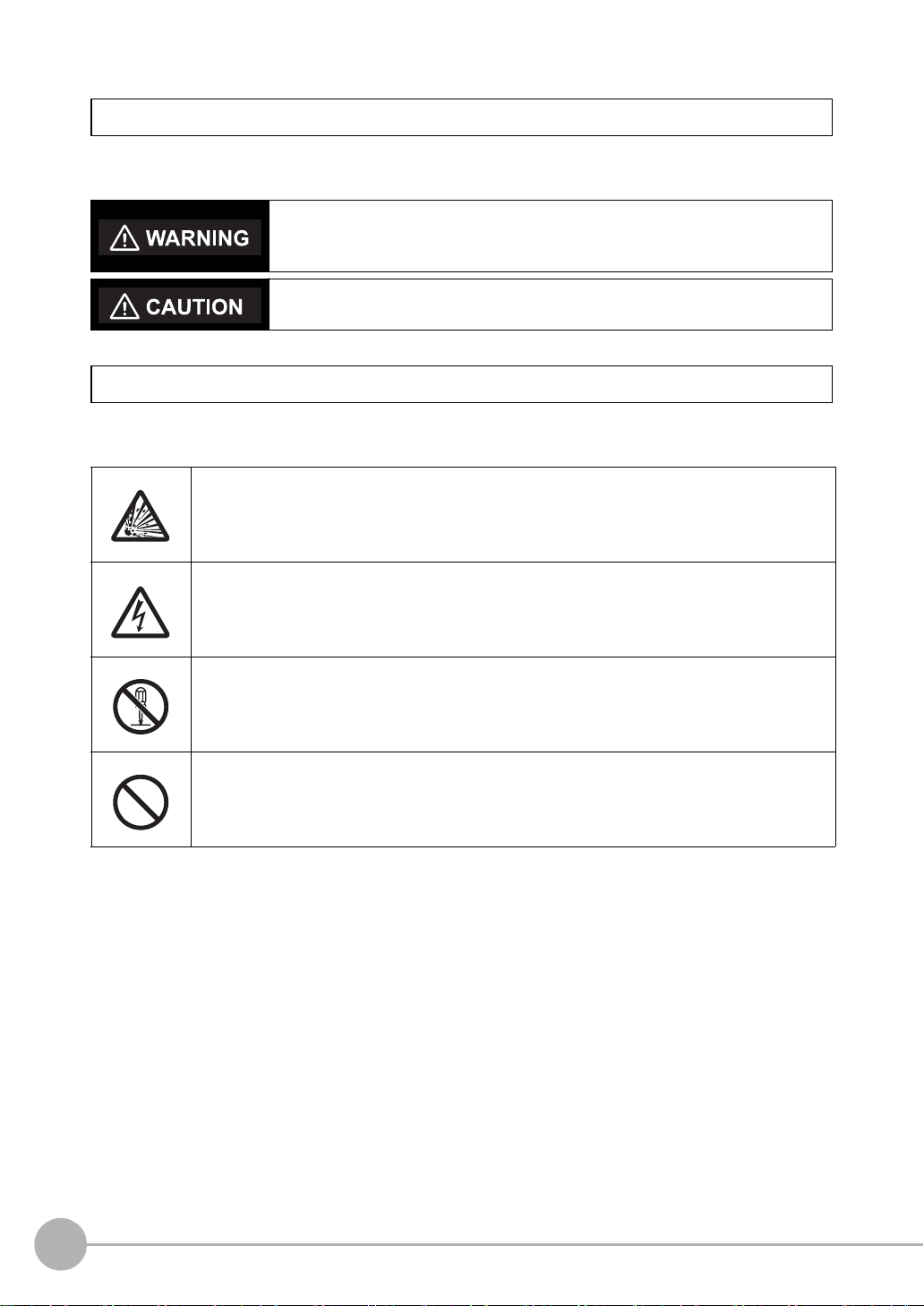
Meanings of Signal Words
The following signal words are used in this manual.
Indicates a potentially hazardous situation which, if not avoided, will result in minor
or moderate injury, or may result in serious injury or death. Additionally there may
be significant property damage.
Indicates a potentially hazardous situation which, if not avoided, may result in
minor or moderate injury or in property damage.
Meanings of Alert Symbols
The following alert symbols are used in this manual.
Indicates the possibility of explosion under specific conditions.
Indicates the possibility of electric shock under specific conditions.
Indicates prohibition when there is a risk of minor injury from electrical shock or other
source if the product is disassembled.
Indicates general prohibitions for which there is no specific symbol.
4
ZR-RX40 User’s Manual

Alert Statements in this Manual
The following alert statements apply to the products in this manual. Each alert statement also appears at the
locations needed in this manual to attract your attention.
This product cannot be used for directly or indirectly detecting human bodies to ensure
safety.
Do not use this product as a human body protection device.
Serious hazard may occur in rare occasions due to ignition, rupture or combustion of
the lithium battery contained in this product.
Never disassemble, deform under pressure, heat or incinerate this product.
Serious hazard may occur in rare occasions due to ignition, rupture or combustion.
Never disassemble, deform under pressure, heat or incinerate the lithium ion battery
pack ZR-XRB1 (GRAPHTEC: B-517).
Injuries from electric shock may occur in rare occasions as the result of disassembly.
Never disassemble, deform under pressure or incinerate the main unit.
Hazard may occur from serious fire or electric shock.
Do not connect voltages exceeding the rated voltage to the signal input terminals.
Fire or hazard may occur in rare occasions from ignition, rupture or combustion.
Do not use battery packs other than ZR-XRB1.
ZR-RX40 User’s Manual
5

Precautions for Safe Use
Be sure to observe the following items as they are very important to ensure safety.
1.Installation environment
• Do not store or use in locations where the temperature exceeds the rated range.
• Do not use in locations where the relative humidity exceeds the 30 to 80 %RH range.
• Do not use in locations subject to steam.
• Do not use in flammable or explodable gas environment.
2.Power supply and wiring
• Do not connect voltages exceeding the rated voltage to signal cables.
• Be sure to check the polarity of the signals when connecting the signal cables.
• When using the battery pack, be sure to read the cautions on the battery pack carefully for correct usage.
• Be sure to use only the specified battery pack.
• Be sure to use only the AC cable and the AC adapter provided as standard accessories.
• Do not connect power supplies exceeding the rated voltage to the AC adapter.
• Be sure to turn off the power supply when connecting to the input terminals.
• Do not touch the input terminals during measurement.
3.Others
• Dispose of this product as industrial waste.
• If there are any troubles, stop usage immediately, turn off the power supply and contact OMRON branch or
sales office.
6
ZR-RX40 User’s Manual

Precautions for Correct Use
Please observe the following precautions to prevent inoperability, misoperation of the product or negative
effects on the performance and the device.
1.Installation Location
Do not install this product in the following locations.
• Locations where the temperature exceeds the rated range
• Locations where severe changes in temperature occur (where condensation occurs)
• Locations subject to corrosive or flammable gases
• Locations subject to dust, salt or iron powder
• Locations subject to direct shock or vibration
• Locations subject to direct sunlight or near heating devices
• Locations where water, oil or chemical products may be splashed
• Locations subject to strong magnetic fields or strong electric fields
2.Power supply, connecting and wiring
• The cables should be wired apart from high-tension or power lines.
Malfunction or damage may occur due to induction.
• After wiring, check the adequacy of power supply voltage, miswiring such as overvoltage/load short-
circuiting and adequacy of load current before turning on the power supply.
Malfunction may occur due to miswiring and such.
• Always turn off the power supply when attaching or removing peripheral devices.
Attaching or removing of peripheral devices with the power supply on can cause malfunction or data
corruption.
3.Installation
• Do not cover the vent hole when using this product.
Leave at least 30cm of installation space around this product.
The generated heat may cause malfunction or damage.
• When measuring temperature, install the product so that the input terminals are not subject to severe
changes in temperature by wind or sunlight.
It may cause calculation errors.
• Do not install this product in a slanted or vertical position.
• Connect the GND terminal for safe measurement. This product must also be grounded when sharing a
common ground level with other devices.
4.Warm up
• For stable measurement, wait at least 30 minutes after turning on the power supply before using.
5.Handling
• Be sure to take backups of captured data in your PC. The captured content may be altered or lost due to
misuse or malfunctions during usage.
• Do not drop or apply strong impact or force to the product.
It may cause malfunction of the monitor or the main unit.
6.Maintenance
• Do not use thinner, benzine, acetone or kerosene to clean this product.
• Calibration should be performed periodically to maintain measurement accuracy.
ZR-RX40 User’s Manual
7

Checking the Accessories
Item Remarks Quantity
Main unit ZR-RX40 1
Start Up Guide 1
Utility disk • Basic PC software “Smart Viewer RX40”
• Start Up Guide PDF files
• User's Manual PDF files
• “Smart Viewer RX40” Software Manual PDF files
AC cable/AC adapter 100 to 240 VAC, 50/60 Hz 1
1
8
ZR-RX40 User’s Manual

Editor's Note
Important
Note
Meaning of Symbols
Menu items that are displayed on the ZR-RX40's LCD screen, and windows, dialog boxes and other GUI
elements displayed on the PC are indicated enclosed by brackets "[ ]".
Visual Aids
Indicates points that are important to achieve the full product performance,
such as operational precautions.
Indicates application procedures.
Indicates pages where related information can be found.
ZR-RX40 User’s Manual
9

MEMO
10
ZR-RX40 User’s Manual

CONTENTS
1.BEFORE USE
Features . . . . . . . . . . . . . . . . . . . . . . . . . . . . . . . . . . . . . . . . . . . . . . . . . . . . 16
Part Names and Functions. . . . . . . . . . . . . . . . . . . . . . . . . . . . . . . . . . . . . 17
Connecting the Power Cable . . . . . . . . . . . . . . . . . . . . . . . . . . . . . . . . . . . 18
Connecting to an AC Power Supply. . . . . . . . . . . . . . . . . . . . . . . . . . . . . . . . . . . 18
Connecting to a DC Power Supply . . . . . . . . . . . . . . . . . . . . . . . . . . . . . . . . . . . 19
Connecting the Analog Input Terminal . . . . . . . . . . . . . . . . . . . . . . . . . . . 21
Terminal Configuration and Signal Types . . . . . . . . . . . . . . . . . . . . . . . . . . . . . . 21
Connection diagram. . . . . . . . . . . . . . . . . . . . . . . . . . . . . . . . . . . . . . . . . . . . . . . 21
Connecting the Logic Input Terminal . . . . . . . . . . . . . . . . . . . . . . . . . . . . 22
Circuit Example of Relay Drive by Alarm Output . . . . . . . . . . . . . . . . . . . . . . . . . 23
Attaching USB Memory . . . . . . . . . . . . . . . . . . . . . . . . . . . . . . . . . . . . . . . 24
Inserting a USB Memory . . . . . . . . . . . . . . . . . . . . . . . . . . . . . . . . . . . . . . . . . . . 24
Connecting to a PC . . . . . . . . . . . . . . . . . . . . . . . . . . . . . . . . . . . . . . . . . . . 25
Connection Using a USB Cable. . . . . . . . . . . . . . . . . . . . . . . . . . . . . . . . . . . . . . 25
LAN Connection. . . . . . . . . . . . . . . . . . . . . . . . . . . . . . . . . . . . . . . . . . . . . . . . . . 26
Using the Battery Pack . . . . . . . . . . . . . . . . . . . . . . . . . . . . . . . . . . . . . . . . 27
Mounting the Battery Pack. . . . . . . . . . . . . . . . . . . . . . . . . . . . . . . . . . . . . . . . . . 27
Charging the Battery . . . . . . . . . . . . . . . . . . . . . . . . . . . . . . . . . . . . . . . . . . . . . . 28
Connecting the Humidity Sensor. . . . . . . . . . . . . . . . . . . . . . . . . . . . . . . . 29
Mounting and Removing the Terminal Unit . . . . . . . . . . . . . . . . . . . . . . . 30
To Remove . . . . . . . . . . . . . . . . . . . . . . . . . . . . . . . . . . . . . . . . . . . . . . . . . . . . . 30
To Mount . . . . . . . . . . . . . . . . . . . . . . . . . . . . . . . . . . . . . . . . . . . . . . . . . . . . . . . 31
Mounting the Extension Terminal Base Set . . . . . . . . . . . . . . . . . . . . . . . 32
Set Contents . . . . . . . . . . . . . . . . . . . . . . . . . . . . . . . . . . . . . . . . . . . . . . . . . . . . 32
To Mount . . . . . . . . . . . . . . . . . . . . . . . . . . . . . . . . . . . . . . . . . . . . . . . . . . . . . . . 32
Mounting the 20 Channel Extension Terminal Set. . . . . . . . . . . . . . . . . . 34
Set Contents . . . . . . . . . . . . . . . . . . . . . . . . . . . . . . . . . . . . . . . . . . . . . . . . . . . . 34
To Mount . . . . . . . . . . . . . . . . . . . . . . . . . . . . . . . . . . . . . . . . . . . . . . . . . . . . . . . 34
Precautions to Observe When Performing Measurement. . . . . . . . . . . . 37
Noise Countermeasures. . . . . . . . . . . . . . . . . . . . . . . . . . . . . . . . . . . . . . . 38
Setting the Date and Time . . . . . . . . . . . . . . . . . . . . . . . . . . . . . . . . . . . . . 39
How to Recharge the Rechargeable Battery . . . . . . . . . . . . . . . . . . . . . . . . . . . . 39
How to Set the Date and Time. . . . . . . . . . . . . . . . . . . . . . . . . . . . . . . . . . . . . . . 39
CONTENTS
ZR-RX40 User’s Manual
11

Changing the Display Language . . . . . . . . . . . . . . . . . . . . . . . . . . . . . . . . 40
2.SETTINGS AND MEASUREMENT
Window names and functions . . . . . . . . . . . . . . . . . . . . . . . . . . . . . . . . . . 42
Key Operation . . . . . . . . . . . . . . . . . . . . . . . . . . . . . . . . . . . . . . . . . . . . . . . 44
(1) CH GROUP . . . . . . . . . . . . . . . . . . . . . . . . . . . . . . . . . . . . . . . . . . . . . . . . . . 44
(2) SPAN/TRACE/POSITION . . . . . . . . . . . . . . . . . . . . . . . . . . . . . . . . . . . . . . . 45
(3) TIME/DIV . . . . . . . . . . . . . . . . . . . . . . . . . . . . . . . . . . . . . . . . . . . . . . . . . . . . 46
(4) MENU . . . . . . . . . . . . . . . . . . . . . . . . . . . . . . . . . . . . . . . . . . . . . . . . . . . . . . . 46
(5) QUIT (LOCAL) . . . . . . . . . . . . . . . . . . . . . . . . . . . . . . . . . . . . . . . . . . . . . . . . 46
(6) Direction keys. . . . . . . . . . . . . . . . . . . . . . . . . . . . . . . . . . . . . . . . . . . . . . . . . 47
(7) ENTER . . . . . . . . . . . . . . . . . . . . . . . . . . . . . . . . . . . . . . . . . . . . . . . . . . . . . . 47
(8) FAST FORWARD key (KEY LOCK). . . . . . . . . . . . . . . . . . . . . . . . . . . . . . . . 47
(9) START/STOP (USB Drive Mode). . . . . . . . . . . . . . . . . . . . . . . . . . . . . . . . . . 48
(10) REVIEW . . . . . . . . . . . . . . . . . . . . . . . . . . . . . . . . . . . . . . . . . . . . . . . . . . . . 49
(11) DISPLAY . . . . . . . . . . . . . . . . . . . . . . . . . . . . . . . . . . . . . . . . . . . . . . . . . . . 50
(12) CURSOR (ALARM CLEAR) . . . . . . . . . . . . . . . . . . . . . . . . . . . . . . . . . . . . . 51
(13) FILE . . . . . . . . . . . . . . . . . . . . . . . . . . . . . . . . . . . . . . . . . . . . . . . . . . . . . . . 51
(14) NAVI . . . . . . . . . . . . . . . . . . . . . . . . . . . . . . . . . . . . . . . . . . . . . . . . . . . . . . . 52
Operation Modes. . . . . . . . . . . . . . . . . . . . . . . . . . . . . . . . . . . . . . . . . . . . . 53
(1) Free Running . . . . . . . . . . . . . . . . . . . . . . . . . . . . . . . . . . . . . . . . . . . . . . . . . 53
(2) Capturing . . . . . . . . . . . . . . . . . . . . . . . . . . . . . . . . . . . . . . . . . . . . . . . . . . . . 54
(3) Dual View Replaying . . . . . . . . . . . . . . . . . . . . . . . . . . . . . . . . . . . . . . . . . . . 54
(4) Replaying . . . . . . . . . . . . . . . . . . . . . . . . . . . . . . . . . . . . . . . . . . . . . . . . . . . . 55
Setting Menus . . . . . . . . . . . . . . . . . . . . . . . . . . . . . . . . . . . . . . . . . . . . . . . 56
(1) AMP settings . . . . . . . . . . . . . . . . . . . . . . . . . . . . . . . . . . . . . . . . . . . . . . . . . 56
(2) DATA settings. . . . . . . . . . . . . . . . . . . . . . . . . . . . . . . . . . . . . . . . . . . . . . . . . 61
(3) TRIG settings . . . . . . . . . . . . . . . . . . . . . . . . . . . . . . . . . . . . . . . . . . . . . . . . . 63
(4) USER settings . . . . . . . . . . . . . . . . . . . . . . . . . . . . . . . . . . . . . . . . . . . . . . . . 68
(5) Interface settings . . . . . . . . . . . . . . . . . . . . . . . . . . . . . . . . . . . . . . . . . . . . . . 70
(6) OTHR settings . . . . . . . . . . . . . . . . . . . . . . . . . . . . . . . . . . . . . . . . . . . . . . . . 71
(7) Other menus. . . . . . . . . . . . . . . . . . . . . . . . . . . . . . . . . . . . . . . . . . . . . . . . . . 73
WEB Server Function . . . . . . . . . . . . . . . . . . . . . . . . . . . . . . . . . . . . . . . . . 84
3.SPECIFICATIONS
Standard Specifications . . . . . . . . . . . . . . . . . . . . . . . . . . . . . . . . . . . . . . . 90
Standard Specifications . . . . . . . . . . . . . . . . . . . . . . . . . . . . . . . . . . . . . . . . . . . . 90
Main Functions. . . . . . . . . . . . . . . . . . . . . . . . . . . . . . . . . . . . . . . . . . . . . . . . . . . 92
Accessory/Option Specifications . . . . . . . . . . . . . . . . . . . . . . . . . . . . . . . 94
Accessories . . . . . . . . . . . . . . . . . . . . . . . . . . . . . . . . . . . . . . . . . . . . . . . . . . . . . 94
Options. . . . . . . . . . . . . . . . . . . . . . . . . . . . . . . . . . . . . . . . . . . . . . . . . . . . . . . . . 94
Humidity Sensor ZR-XRH1 . . . . . . . . . . . . . . . . . . . . . . . . . . . . . . . . . . . . . . . . . 95
12
ZR-RX40 User’s Manual

External Dimensions. . . . . . . . . . . . . . . . . . . . . . . . . . . . . . . . . . . . . . . . . . 96
INDEX . . . . . . . . . . . . . . . . . . . . . . . . . . . . . . . . . . . . . . . . . . . . . . . . . . . . . . 97
Revision History . . . . . . . . . . . . . . . . . . . . . . . . . . . . . . . . . . . . . . . . . . . . 100
CONTENTS
ZR-RX40 User’s Manual
13

MEMO
14
ZR-RX40 User’s Manual

BEFORE USE
Features 16
Part Names and Functions 17
Connecting the Power Cable 18
Connecting the Analog Input Terminal 21
Connecting the Logic Input Terminal 22
Attaching USB Memory Device 24
Connecting to a PC 25
Using the Battery Pack 27
Connecting the Humidity Sensor 29
Mounting and Removing the Terminal Unit 30
Mounting the Extension Terminal Base Set 32
Mounting the 20 Channel Extension Terminal Set 34
Precautions to Observe When Performing Measurement
Noise Countermeasures 38
Setting the Date and Time 39
Changing the Display Language 40
1
BEFORE USE
37

Features
The ZR-RX40 (with color monitor and internal memory) are compact, lightweight, multi-channel data loggers.
ZR-RX40 are provided with 20 channels as a standard measurement feature, or can be extended up to 200
channels by attaching additional terminal sets.
ZR-RX40 is equipped with an internal flash memory, and attaching USB memory device also allows you to
directly capture a large volume of data to USB memory device.
Furthermore, the data loggers are equipped with USB and Ethernet interfaces to a PC to enable system
configurations according to your application.
The Ethernet feature includes WEB and FTP server functions which allow monitoring from a remote location
and data transfer.
Input
• Adoption of a pluggable M3 screw type input terminal facilitates wiring.
• The ZR-RX40 is provided with 20 channels as a standard measurement feature, or can be extended up to 200
channels by attaching additional terminal sets.
• All channels are isolated, enabling measurement of signals of different references.
Display & Operation
• With the ZR-RX40's 5.7-inch TFT color liquid crystal display, you can confirm the waveforms of measured data and
each channel's settings at a glance.
• Easy operation is achieved through a straightforward menu structure and key allocation which resembles mobile
phones.
Data Capture
• Data can be directly captured and maintained in the internal or USB memory device.
• Internal memory used for the built-in memory maintains captured data even after the power is turned off.
• The Internal memory can be used with disk images thus multiple data items can be maintained.
Data Control & Processing
• The PC software provided lets you set conditions and monitor data on a PC.
• The USB drive mode function enables the ZR-RX40's internal memory to be recognized as an external drive by
your PC. (Connect the ZR-RX40 to your PC and turn on the power supply to the ZR-RX40 while holding down the
START key.)
• Captured data can be read from the PC software to files and displayed for processing.
• Data can be transferred off-line to a computer using USB memory device.
• The WEB server function enables control and monitoring from a remote location without using dedicated software.
• The FTP server function enables handling internal memory and USB memory data from a PC.
16
Features
ZR-RX40 User’s Manual

Part Names and Functions
PC interface terminals
ʯUSB
ʯLAN
Monitor
Power switch
Operation status LED
ʯPOWER : ON when the power is ON
ʯSTART : ON during data capture
ʯCHARGE : ON while the battery is charging
Control panel keys
Battery cover
Contains battery pack ZR-XRB1 (Option)
This section describes the names and function of parts of the ZR-RX40.
AC adapter jack
GND terminal
1
BEFORE USE
USB memory terminal
ZR-RX40 User’s Manual
External input/output terminal
ʯLOGIC/PULSE : LOGIC/PULSE input
ʯEXT TRIG : Trigger input
ʯALARM : Alarm output
Analog signal input terminals
Power jack for the humidity sensor
Part Names and Functions
17

Connecting the Power Cable
AC adapter
AC cable
AC adapter cable
This section describes how to connect the power cable and turn on the power. The connection method will vary
depending on the type of power supply used.
Connecting to an AC Power Supply
Use the AC cable and AC adapter that are provided as accessories.
Important
Be sure to use only the AC cable and the AC adapter provided as standard accessories.
1 Plug the AC cable into the AC adapter.
2 Connect the output side of the AC adapter to the AC adapter connector.
18
Connecting the Power Cable
ZR-RX40 User’s Manual

3 Using the flat-blade screwdriver, press against the minus (-) button above the GND terminal, while
The grounding cable is not provided as a standard
accessory and must be prepared separately.
[Recommended Cord Diameter: AWG18/UL1007]
Note
DC drive cable
ZR-XRD1 (option)
White (+ side)
Shielded lead (- side)
connecting the grounding cable to the ZR-RX40. Connect the other end of the cable to ground.
4 Plug the AC cable into the mains power outlet.
5 Press the power switch on the ZR-RX40 to the ON side to turn on the power.
Important
Connect the GND terminal for safe measurement. The ZR-RX40 must also be grounded when sharing a common
ground level with other devices.
Connecting to a DC Power Supply
1
BEFORE USE
Use the DC cable (option: ZR-XRD1).
Important
Be sure to use the separately sold DC cable (ZR-XRD1). Do not apply voltages exceeding the rated voltage (8.5 to 24
VDC).
1 Connect the DC output side to the power supply connector on the ZR-RX40.
ZR-RX40 User’s Manual
Connecting the Power Cable
19

2 Connect the DC input side to the DC power supply.
Important
Be sure to check the polarity of the power supply when connecting the DC cable.
3 Press the power switch on the ZR-RX40 to the ON side to turn on the power.
20
Connecting the Power Cable
ZR-RX40 User’s Manual

Connecting the Analog Input Terminal
CH1 CH20
+
−
b
Direct voltage
A
B
b
b
Lead wire resistance should be 10 Ω or below
per wire, and equivalent among the three wires.
Direct current
Shunt resistance
Ex: for current in the 4 to 20 mA range,
apply a resistance of 250 Ω ( 0.1%) and
perform measurement in the 1 to 5 V range.
Direct voltage input Thermocouple input
Resistance temperature detector input Direct current input
This section describes how to connect the analog input terminal.
Terminal Configuration and Signal Types
Connection diagram
Compensation
copper wire
1
BEFORE USE
+...........................High-voltage terminal (terminal for high-voltage input signals)
–........................... Low-voltage terminal (terminal for low-voltage input signals)
b........................... Dedicated terminal when connecting resistance temperature detector
*Resistance temperature detector input terminals A (+) and B (-) are isolated within each channel. Terminal b is
shorted within all channels.
Item Description
Input configuration Isolated input, scanning
Analog voltage 20, 50, 100, 200, 500 mV/F.S.; 1, 2, 5, 10, 20, 50 V/F.S.; 1-5V
Thermocouples K, J, E, T, R, S, B, N, W (WRe 5-26)
Resistance temperature detector PT100, JPT100, PT1000 (IEC751)
ZR-RX40 User’s Manual
Connecting the Analog Input Terminal
21

Connecting the Logic Input Terminal
Logic alarm cable (ZR-XRL1)
The logic alarm cable (ZR-XRL1) enables logic/pulse input, external trigger input, and alarm signal output.
Connect the logic alarm cable (ZR-XRL1) to the external input/output terminal as shown below.
Logic/Pulse Specifications
Item Description
Number of input channels 4
Input voltage range 0 to +24V max. (single-ended ground input)
Threshold level Approx. +2.5V
Hysteresis Approx. 0.5 V (+2.5 to +3 V)
*Switch between logic and pulse input.
Trigger Input Specifications
Item Description
Number of input channels 1
Input voltage range 0 to +24V max. (single-ended ground input)
Threshold level Approx. +2.5V
Hysteresis Approx. 0.5 V (+2.5 to +3 V)
Alarm Output Specifications
Item Description
Number of output channels 4
Output format Open collector output
+5 V, 10 KΩ pull-up resistance
Contact capacity 5 V to 24 V, 100 mA or below
22
Connecting the Logic Input Terminal
ZR-RX40 User’s Manual

Circuit Example of Relay Drive by Alarm Output
Alarm Output Circuit
External Device
+24V
This relay turns ON when alarm is generated.
ZR-RX40
+5V
10KΩ
Orange with red dotted line : 1
Orange with black dotted line : 2
Grey with red dotted line : 3
Grey with black dotted line : 4
White with red dotted line : 1
White with black dotted line : 2
Yellow with red dotted line : 3
Yellow with black dotted line : 4
Pink with red dotted line : Trigger input
Pink with black dotted line
Shielded
GND
Logic/Pulse input
Alarm output
Wiring
Cable tips are bare tips. Perform wiring for the necessary functions.
Signal Name Channel Number Wire Color
Logic/Pulse output 1 Orange with red dotted line
2 Orange with black dotted line
3 Grey with red dotted line
4 Grey with black dotted line
Alarm output 1 White with red dotted line
2 White with black dotted line
3 Yellow with red dotted line
4 Yellow with black dotted line
Trigger input Pink with red dotted line
GND Pink with black dotted line
Shielded
1
BEFORE USE
*Switch between logic and pulse.
ZR-RX40 User’s Manual
Connecting the Logic Input Terminal
23

Attaching USB Memory Device
Attaching USB memory device to the ZR-RX40 allows you store measured data directly.
Inserting a USB Memory Device
Attach the USB memory device to the USB memory terminal.
USB memory device
Important
<Specifications of supported USB memory>
• Power source : +5 V
• Power consumption : 250 mA or below
• Capacity : No limit (except each file must be within 2 GB)
* USB memory device with security functions such as fingerprint authentication cannot be used.
24
Attaching USB Memory Device
ZR-RX40 User’s Manual

Connecting to a PC
USB cable
Use the USB, LAN Interface to connect the ZR-RX40 to a PC.
Connection Using a USB Cable
Use the USB cable to connect the ZR-RX40 to a PC.
Note
If the USB cable is used, install the USB driver in your PC.
"Installing the USB driver" in the Software Manual
1
BEFORE USE
Note
The USB connector is adjacent to the LAN connector. Make sure the cable is inserted into the correct connector.
ZR-RX40 User’s Manual
Connecting to a PC
25

LAN Connection
LAN cable
(crossing)
HUBLAN cable
(straight)
LAN cable
(straight)
Use a LAN cable to connect the ZR-RX40 to a PC.
Cable Types
• Use a crossing cable when connecting directly to a PC, without using a hub.
LAN cable
26
• Use a straight cable when using a hub.
Connecting to a PC
ZR-RX40 User’s Manual

Using the Battery Pack
②
①
Attach the battery with care of polarity
and insertion direction.
Note
Note
Be sure to use the dedicated battery pack (option: ZR-XRB1).
Mounting the Battery Pack
1 While lightly pushing the grip of the battery cover, slid the cover in the direction indicated by the
arrow.
2 Attach the battery pack (ZR-XRB1).
1
BEFORE USE
Either one or two battery packs can be attached.
To connect one pack, connect to either one of the connectors.
Attaching two battery packs allows longer operational time.
When attaching two battery packs, make sure the battery levels are equivalent.
Do not use a new battery with an old battery at the same time.
When attaching two battery packs, make sure the remaining amount are same.
If you are not sure about the amount, charge each battery and then attach full-charged two battery packs.
ZR-RX40 User’s Manual
Using the Battery Pack
27

3 Attach the battery cover.
Note
Charging the Battery
Expected time required for charging: • battery pack x 1: approx. 4 hours
• battery pack x 2: approx. 8 hours
The battery pack is charged by mounting it in the ZR-RX40, attaching AC adapter to the ZR-RX40.
1 Mount the battery pack in the ZR-RX40.
"Mounting the Battery Pack" p.27
2 Turn on the power to the ZR-RX40.
"Connecting the Power Cable" p.18
The CHARGE LED lights.
CHARGE LED
28
Using the Battery Pack
ZR-RX40 User’s Manual
 Loading...