

Omron ZN-KMX21 Instruction Sheet
Model
ZN-KMX21-
Power Sensor Station
INSTRUCTION SHEET
Thank you for selecting OMRON product. This sheet primarily
describes precautions required in installing and operating the product.
Before operating the product, read the sheet thoroughly to acquire
sufficient knowledge of the product. For your convenience, keep the
sheet at your disposal.
TRACEABILITY INFORMATION:
Importer in EU:
Omron Europe B.V.
Wegalaan 67-69
2132 JD Hoofddorp,
The Netherlands
The following notice applies only to products that carry the CE mark:
Notice:
This is a class A product. In residential areas it may cause radio
interference, in which case the user may be required to take adequate
measures to reduce interference.
Manufacturer:
Omron Corporation,
Shiokoji Horikawa, Shimogyo-ku,
Kyoto 600-8530 JAPAN
●Warning Indications
WARNING
The mounting magnets provided with the product have
strong magnetism. If the product is mounted using these
magnets, anyone wearing a heart pacemaker must not
operate the product; or the product must not be in proximity
of such a person.
This product contains lithium batteries. Serious injury may
occur due to fire or explosion. Do not attempt to
disassemble the product, deform it by applying pressure,
heat it in a high temperature (100°C℃ or more), or burn it
for disposal.
CAUTION
Tighten the terminal screws at a recommended torque: 0.69
to 0.88N·m. Make sure that the screws are not slanted away
from the center after tightened.
A minor or moderate injury or property damage may occur
due to explosion. Do not use the product in an environment
containing an inflammable or explosive gas.
An electric shock may occur. Do not replace the batteries
when the unit is clamped to a conductor for measurement.
PRECAUTIONS FOR CORRECT USE
1. Avoid installing the product in the following places:
• Places exceeding the rated ambient temperature
• Places exposed to extreme temperature changes (where condensation occurs)
• Places subject to relative humidity exceeding the rated humidity range
• Places subject to corrosive or flammable gases
• Places subject to mist, droplets, coarse particles, fiber, salt, metal dust, or large amount of
particles
• Places subject to direct shock or vibration
• Places subject to direct sunlight
• Places subject to exposure to water, oil, or chemical splashes
• Places subject to strong magnetic field or electric field
• Outdoors
2. Wiring
• Wire the product cable separately from high-voltage or power lines. Placing them in the same
wiring or the same duct may cause induction, resulting in the product malfunction or damage.
• Make sure that the I/O terminals are inserted or removed with the power turned OFF. Doing
this with the power ON may result in a failure.
• When using a DC cable, connect the white-lined wire of the cable to the power input (24 VDC
± 3%) and the non-lined wire to 0V.
3. Mounting screw holes
• The screw holes provided on the product are M3 and 4 mm deep. Do not screw deeper than 4
mm, which may damage the product.
4. Operation
When using the product, also read KM series power sensor/monitor instruction sheets for
necessary information relevant to the product.
• The Power Sensors/Monitors that can be connected to the product are KM20-B40-FLK,
KM50-C, KM50-E, KM100, KM-N1-FLK, KM-N2-FLK and KM-N3-FLK.
To directly connect KM-N1-FLK, KM-N2-FLK and KM-N3-FLK to ZN-KMX21-, please
purchase a separately sold dedicated connection cable ZN9-KMC30-N.
* 9 5 2 1 9 5 8 - 0 E *
OMRON Corporation
©
2011
All Rights Reserved.
●Perchlorate regulations by the State of California, USA
This product uses a lithium battery that contains perchlorate that is
regulated by California State Law. Appropriate measures must be taken to
comply with regulations.
For details, refer to the URL as below:
www.dtsc.ca.gov/hazardouswaste/perchlorate
PRECAUTIONS ON SAFETY
●Meanings of Signal Words
Indicates a potentially hazardous situation which, if
WARNING
CAUTION
●Meaning of Precaution Symbols
●Mandatory Requirement
Indicates a general mandatory requirement.
●Prohibition
Indicates general prohibition.
●Electric Shock Warning
Warns against an electric shock under specific conditions.
●Explosion Warning
Warns against an explosion under specific conditions.
not avoided, will result in minor or moderate injury, or
may result in serious injury or death. Additionally
there may be significant property damage.
Indicates a potentially hazardous situation which, if
not avoided, may result in minor or moderate injury or
in property damage.
PRECAUTIONS FOR SAFE USE
Observe the following precautions to ensure safe operation.
• Do not install the product in the places subject to exposure to water, oil, or chemical splashes.
• Only the provided AC adapter (not other) must be used when using AC power supply.
• If a voltage that exceeds the rated voltage is applied to the AC adapter, smoking may occur. Do
not connect a power supply that exceeds the rated voltage. In a situation where a voltage
higher than the rating is applied, use protective equipment so that the power supply voltage
does not exceed the rated voltage.
• Dispose of the product as industrial waste.
• Do not let the product drop or subject it to a shock, which may cause its damage or malfunc-
tion. Use screws to secure the product when mounting it on the wall. Stop using the product if
it has been applied with a strong impact.
• When inserting or removing an SD card, securely hold the product to prevent it from dropping,
which may cause a damage. Do the same when inserting or detaching an AC adapter, alarm
output cable, or sensor connector.
• Do not bring the product close to magnetic products (e.g. magnetic cards), sensitive electronics
equipment (e.g. computers or clocks), when the product is attached with the mounting magnets.
• Small pieces may be chipped off the mounting magnets when they are attracted to the surface.
Make sure the pieces do not enter the eyes. Consult a medical doctor if this happens.
• When using the mounting magnets to install the product, take caution not to allow a finger to
be caught between the product(s) and the magnetic surface.
• Do not install the product at a high place when using the mounting magnets.
• Apply an appropriate load to the alarm output terminals to prevent possible smoking.
• If liquid crystal leaks due to a damage to the LCD panel, take caution not to allow it to contact
your skin, to be inhaled or swallowed. If it has contacted your skin or entered your mouth, seek
medical attention.
• Take anti-static electricity measures (e.g. touching grounded metal object) when handling the
product.
■ Applicable standards
・EN61326-1
・Electromagnetic environment : Industrial electromagnetic environment
(EN/IEC 61326-1 Table 2)
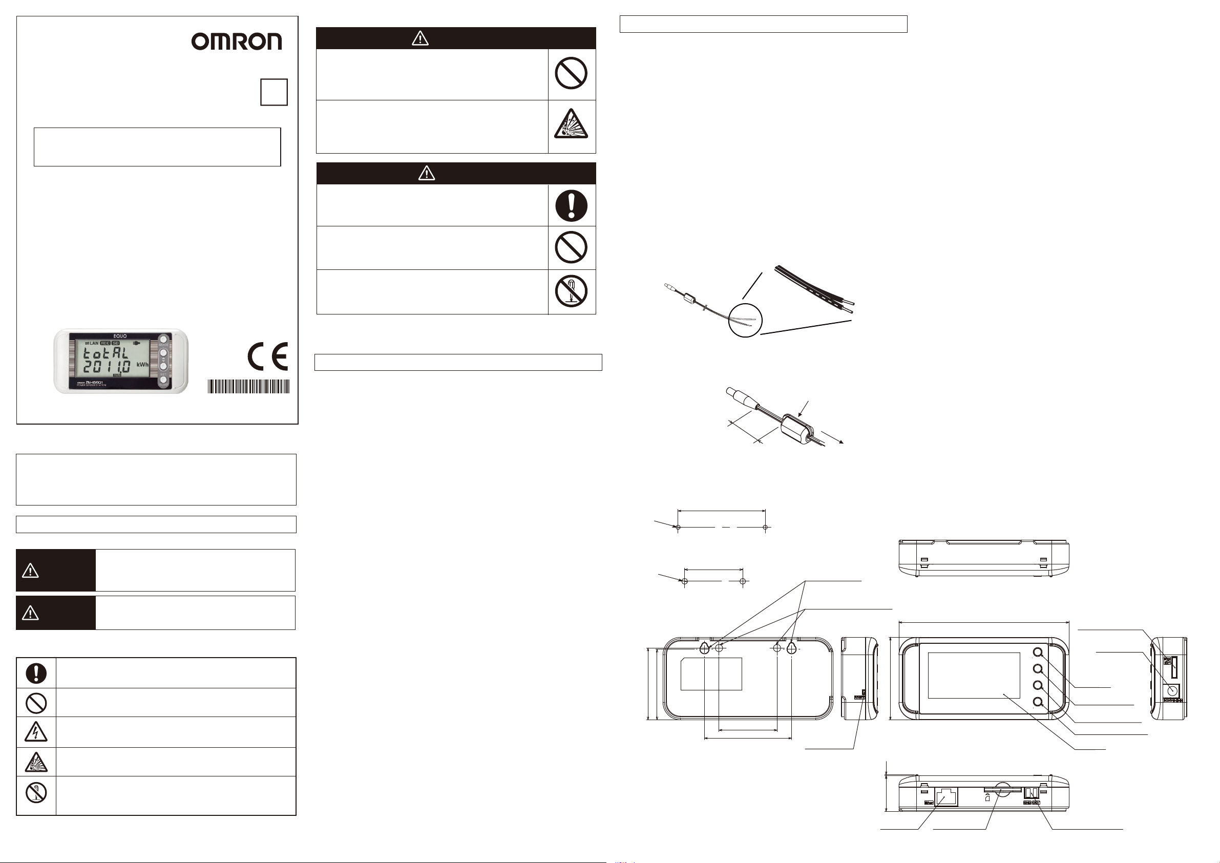
• Use a ferrite core to reduce the noise to/from other device when supplying power to the unit
via a DC cable. To use the provided DC cable, attach the provided ferrite core as shown
below.
Portable Power Monitor unit side
approx. 100 mm
Single winding
Power supply side
■Dimensions
60
2-M3
Screw hook holes dimensions
2-4 Dia.
Mounting hole process dimensions
49.4
48.6
40
40
60
Screw hook hole
Mounting screw hole 2-M3,
4 mm in depth
56.8
Reset switch
117.2
Sensor head connector
Power supply
input terminal
MODE key
Select key
(upper direction)
Select key
(lower direction)
SET/REC/STOP key
Display
●Disassembly Prohibition
Indicates the possibility of accidents such as an electric shock
caused by unit disassembly.
24.6 0.7
LAN port
SD card slot Alarm output terminal
(Unit: mm)
■Overview and Features
By connecting the power monitor/sensor KM series (sold separately), the ZN-KMX21-□
allows you to record the measured data of the power monitor/sensor (KM series) and set
various operations.
●Display and judgment output
The display of the measured data can be switched with the ▲ and ▼ keys. Also,
you can select the measurement target of the monitoring target and set the
threshold value to output an alarm from the output terminal.
●Data output and viewing
Measurement values can be recorded to the unit's memory and the recorded
measurement values can be stored into the SD card.
SD card (*): Data is in CSV format.
By using the software, the measured values recorded with multiple sensors can be
converted into graphs and unified into one file.
* The operation has been checked with the HMC-SD291 2GB SD card
(Recommended SD card).
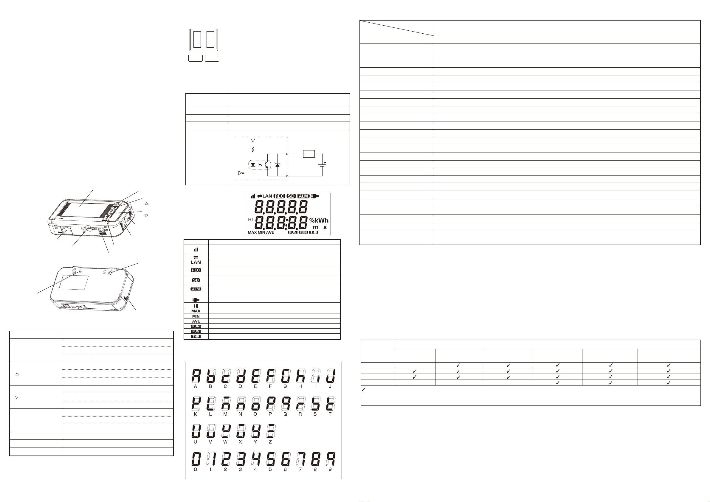
■Names and Functions
Display
Mounting
screw hole
Name
MODE key
LAN port
SD card slot
Function
Switches operating modes
Releases error and alarm (holding)
SET/REC/STOP key
Alarm output terminal
Cancels during settings
Item select key
( key)
Moves setting items (upper direction)
Switches display screens (reverse direction)
Changes the setting value (increasing)
Item select key
( key)
Moves the setting items (lower direction)
Switches the display screens (forward direction)
Changes the setting value (decreasing)
Confirms the setting value
SET/REC/STOP key
Starts/stops record (holding)
Saves recorded data to the SD memory card.
Mounting screw hole
Screw hook hole
Reset switch
Used to secure screws (M3x4 mm female hole)
For screw head hook
Restarts the unit.*
* Used when an SD card is not available when recording stops, or when error
recovery cannot be made.
MODE key
Item select key
( key)
Item select key
( key)
Sensor head
connector
AC adapter terminal
Screw hook hole
Reset switch
■Alarm Output Specifications
●Terminals
GND OUT
●Output Specifications
Do not directly connect the external power supply between OUT and GND.
Be sure to connect the load.
External power
supply voltage
Load current
ON residual voltage
OFF leakage current
Internal circuit
diagram
Terminal names are inscribed on the unit.
For wire used for a terminal block,consider the following.
Wire length:30m and less
(1) OUT
Judgment result allocated in THR mode is output.
(2) GND
Common terminal.
12 to 24 VDC ±10%
45 mA max.
1.2 V max.
0.1 mA max.
OUT
GND
12 to 24 VDC
Load
■Display Unit
Display Meaning and operation when turned on
Integral power consumption reset interval is set.
The setting is OFF when it is not displayed.
Communication with LAN cable.
LAN cable is connected and network communication is possible.
Recording data into the internal memory.
Recording start wait using timer when blinking.
SD card has been inserted.
SD card is being accessed while light blinking.
A total integrated power consumption has exceeded the specified
upper threshold value.
Power is supplied.
Indicates the upper limit threshold value.
Indicates the maximum total momentary power value.
Indicates the minimum total momentary power value.
Indicates the average total momentary power value.
The unit is currently operating in RUN mode.
The unit is currently operating in FUN mode.
The unit is currently operating in THR mode.
■7-segment Display List
0V
External
power
supply
■Ratings
Model
Item
Connectable Power Sensor/Monitor
KM20-B40-FLK, KM50-C, KM50-E, KM100, KM-N1-FLK, KM-N2-FLK and KM-N3-FLK
Max. Number of Connectable
Power Sensor/Monitor Units
Display
Recording Interval
Recorded data
Operation Function
7-seg. 5-digit 2-step LCD display, auxiliary information indicator displays
1 s, 2 s, 5 s, 10 s, 20 s, 30 s, 1 min.
Momentary power, Integrated power, Power factor, Sum of pulse input counts 1 and 2
Integrated power total sum, integrated momentary power, electricity rate total sum
Recording Mode
External Output
Communication Interface
Memory Capacity (Internal)
Memory Capacity (External)
Power Supply
Current Consumption
Operating Temperature
Operating Humidity
Storage Humidity/Temperature
Internal memory: approx. 200 data items (at maximum load); approx. 6800 data items*5 (at minimum load)
SD card with SDHC compatibility (Save measured values, save and read setting values)
DC input: 24 VDC±10%, AC adapter: 100 to 240 VAC/50 to 60 Hz
80 mA max. (at 24 VDC); 70 mA max. (AC adapter used)
Without Ethernet: -10°C to 40°C (no condensation or icing) With Ethernet: 0°C to 40°C (no condensation or icing)
-15°C to +60°C, 20 to 85%RH (no condensation or icing)
Alarm output (Photocoupler output) *4
Ethernet (10BASE-T, 100BASE-TX)
20 to 85%RH (no condensation or icing)
Insulation Resistance
Withstand Voltage
Vibration Resistance
Shock Resistance
10 to 150 Hz, 0.7 mm double amplitude, acceleration: 50 m/s2 for each in X, Y and Z directions for 80 min
150 m/s2 in 6 directions (+/-X, +/-Y, and +/-Z directions), 3 times each*6
Material
Degree of Protection
Mounting
Magnet mounting, screw mounting, hook, free standing
Weight (in Package)
Accessories
*1: Only supported for KM50-C and KM50-E.
*2: Automatically writes the data to the SD memory card when the internal memory reaches its capacity and continues recording until the SD card memory capacity reaches its limit. The
unit stops operation if there is no SD memory card inserted when the internal memory reaches its capacity. (Recording can be resumed after inserting an SD memory card and
outputting the data to it at a press of button.)
*3: Continues the recording of the latest measured values until the internal memory reaches its capacity. (If the internal memory capacity exceeds the capacity, data is overwritten from
the oldest one in the memory.)
*4: Output when the integrated power upper limit specified in THR mode is exceeded.
*5: The maximum load is applied when 10 KM50-� units are connected; and the minimum load, when a single KM20-B40-FLK is connected.
*6: The vibration resistance when mounted using the ZN9-EM01-S magnets (separately sold): 10 to 55 Hz, 0.3mm double amplitude, acceleration: 20m/s2 for each in X, Y and Z
directions for 50 min. The installation place must be free from physical shock.
*7: OMRON's XW4B-02B1-H1 connector.
*8: This provided AC adapter must be used.
*9: An AC adapter is provided in the ZN-KMX21 package; and a DC cable and ferrite core are included in the ZN-KMX21-A package.
Alarm Output Connector
Instruction Sheet (This sheet), Startup Guide,
*7, AC Adapter*8, *9, DC Cable*9, and Dedicated Connection Cable
●Declaration of hazardous substances
Toxic or hazardous substances and elements
Name
PCB
Lead (Pb)
–
Mercury (Hg)
Enclosure
Accessory
Cable
– –
: Indicates that this toxic or hazardous substance contained in all of the homogeneous materials for this part is below the limit requirement in SJ/T11363-2006.
–: Indicates that this toxic or hazardous substance contained in at least one of the homogeneous materials used for this part is above the limit requirement in
SJ/T11363-2006.
Cadmium
(Cd)
–
ZN-KMX21-□
31 units
Continue mode*2, Ring mode *3
20 MΩ (500 VDC)
1000 VAC, 50/60 Hz, 1 min.
ABS
IP30
Approx. 500 g
Hexavalent chromium
Polybrominated biphenyl
(Cr(VI))
(PBB)
*1
*
6
Polybrominated diphenyl ether
(PBDE)
 Loading...