

Omron ZN-DPS1- *** -S Instruction Sheet
形
ZN-DPS1
微差圧センサヘッド
□□-S
・エアチューブを壁面などに設置する場合、振動が伝わらないように設置
下さい。正しく測定が行われない場合があります。
4.その他
・定格以上の圧力をかけないでください。誤動作あるいは破損の原因にな
ることがあります。
■取付方法
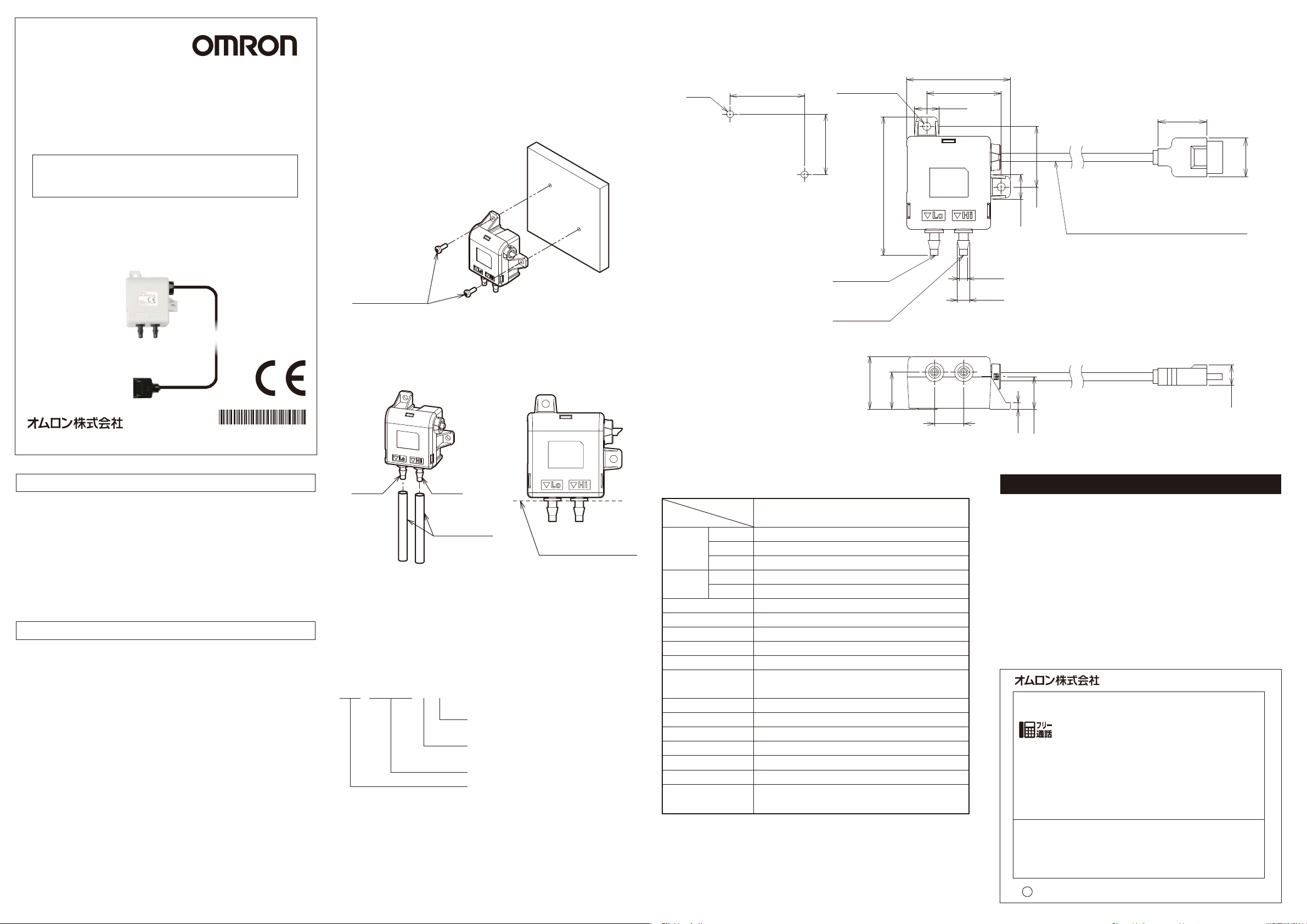
ネジ穴を利用して壁などに固定してください。
付属ネジはM3×8です。
■外形図
2-M3
32±0.2
2-φ3.5取付穴
26±0.2
44.4
32
10.5
21
16.7
取扱説明書
このたびは、本 製 品をお買い 上げいただきまして、まことにありがとうございます。
ご使用に際しては、次の内容をお守りください。
・電気の知識を有する専門家がお取り扱いください。
・
この取扱説明書をよくお読みになり、十分にご理解のうえ、正しくご使用ください。
・この取扱説明書はいつでも参照できるよう大切に保管してください。
* 2 1 5 4 3 8 0 - 7 E *
OMRON Corporation 2011-2018 All Rights Reserved.
©
安全上の要点
本製品を安全に使用するため、以下のことを守ってください。
・水・油・化学薬品の飛沫がある場所には設置しないでください。
・廃棄する時は、産業廃棄物として処理ください。
・破損・誤動作の可能性があるため、本製品を落下させるなどの強い衝撃
を与えないでください。落下による破損防止のため、壁面などへのねじ
止め固定を行ってください。強い衝撃を与えてしまった場合、使用を中
止してください。
■Applicablestandards
・EN61326-1
・Electromagneticenvironment:Industrialelectromagneticenvironment
(EN/IEC 61326-1 Table2)
使用上の注意
1.下記の設置場所では使用しないでください。
・周囲温度が定格の範囲を超える場所
・温度変化が急激な場所(結露する場所)
・相対湿度が定格の範囲を超える場所
・腐食性ガス、可燃性ガスがある場所
・ミスト、液滴、粗大粒子、繊維、塩分、金属粉など、もしくは大量の粒
子がある場所
・振動や衝撃が直接加わる場所
・直射日光が当たる場所
・水・油・化学薬品の飛沫がある場所
・強磁界・強電界がある場所
2.配線について
・高圧線、動力線と本製品の配線は別配線としてください。同一配線ある
いは同一ダクトにすると誘導を受け、誤動作あるいは破損の原因になる
ことがあります。
・本製品は形ZN-DPX□□-S以外のコントローラとは接続しないでくださ
い。また、本製品をコントローラを取り付けた状態で本製品のみを持た
ないでください。
3.微差圧測定について
・本製品は測定を行うために、微小な空気の流れを作る必要があります。
正確な測定を行うためには接続するエアチューブの長さをなるべく短く
し、エアチューブが歪曲しないようにしてください。歪曲したエアチュ
ーブを接続したり、1mを超えるエアチューブを接続すると正しく測定
が行えない場合があります。
取付ネジ(M3)
圧力導入口にエアチューブを差し込んでください。圧力導入口の上部に高
圧側(▼Hi)、低圧側(▼Lo)の刻印があります、測定対象に応じて適切
に接続してください。高圧側の圧力が高いと計測値は正値、低圧側の圧力
が高いと計測値は負値になります。
高圧側低圧側
エアチューブ
コントローラのセンサヘッド接続コネクタ(メス)に本製品のコネクタ(オス)
を挿入してください。
コントローラの取扱説明書に記載されている取付方法にしたがって設置を
行ってください。
ここまでエアチューブを
挿入ください
■形式について
ZN-DPS1□□-S
校正証明書の有無
(記号無し:証明書なし、C:証明書付き)
接続タイプ区別
(1:ケーブル長1.5m、5:ケーブル長10m)
差圧センサヘッド・測定方式
製品シリーズ名
■校正について
微差圧センサヘッドの校正は、必ず当社へご依頼ください。
当社へ送付の際には、内部へ異物が入らないようご注意ください。
取付穴加工寸法
低圧側導入口
高圧側導入口
22.5
59.6
15.8
12.6
■定格
形式
項目
測定範囲
差圧
温度影響
使用温度範囲
保存温度範囲
使用湿度範囲
保存湿度範囲
適用ガス種
振動(耐久)
衝撃(耐久)
保護構造
材質
取付方法
適用エアチューブ径
重量(梱包状態)
付属品
*定格環境下で精度は、0.1Pa/年未満のオフセットが発生する可能性があり
ます。
測定精度
分解能
ゼロ点
スパン
測定値の3%±0.2Pa(23℃、966mbarにて)*
−15〜+50℃(結露、氷結しないこと)
35〜85%RH(結露なきこと)
35〜85%RH(結露、氷結しないこと)
10〜150Hz 複振幅0.7mm 加速度50m/s
150m/s2 6方向各3回(上下、左右、前後)
取扱説明書、エアチューブ1m×2
ZN-DPS1□-S
−500〜+500Pa
0.1Pa
影響なし(測定分解能以下)
指示値の0.5%未満/10℃
0〜50℃
空気、窒素
2
X、Y、Z各方向 80min
IP30
ABS
ネジ取り付け
外径φ6mm、内径φ4mm
約500g
取付ネジ(M3×8)×2
φ3.5
φ5.2
10.5
2.7
26
13.9
ビニル絶縁丸型コードφ3.43芯
(導体断面積:0.08mm2/絶縁体径:φ0.95mm)
標準長さ1.5m
ご承諾事項
当社商品は、一般工業製品向けの汎用品として設計製造されています。従いまして、次に
掲げる用途での使用を意図しておらず、お客様が当社商品をこれらの用途に使用される際
には、当社は当社商品に対して一切保証をいたしません。ただし、次に掲げる用途であって
も当社の意図した特別な商品用途の場合や特別の合意がある場合は除きます。
(a)高い安全性が必要とされる用途(例:原子力制御設備、燃焼設備、航空・宇宙設備、鉄
道設備、昇降設備、娯楽設備、医用機器、安全装置、その他生命・身体に危険が及び
うる用途)
(b)高い信頼性が必要な用途(例:ガス・水道・電気等の供給システム、24時間連続運転
システム、決済システムほか権利・財産を取扱う用途など)
(c)厳しい条件または環境での用途(例:屋外に設置する設備、化学的汚染を被る設備、
電磁的妨害を被る設備、振動・衝撃を受ける設備など)
(d)カタログ等に記載のない条件や環境での用途
*(a)から(d)に記載されている他、本カタログ等記載の商品は自動車(二輪車含む。以下同
じ)向けではありません。自動車に搭載する用途には利用しないで下さい。自動車搭載
用商品については当社営業担当者にご相談ください。
*上記は適合用途の条件の一部です。当社のベスト、総合カタログ、データシート等最新版
のカタログ、マニュアルに記載の保証・免責事項の内容をよく読んでご使用ください。
●製品に関するお問い合わせ先
お客様相談室
インダストリアルオートメーションビジネスカンパニー
クイック オムロン
0120-919-066
携帯電話・PHS・IP電話などではご利用いただけませんので、下記の電話番号へおかけください。
電話
055-982-5015
■営業時間:8:00〜21:00 ■営業日:365日
●FAXやWebページでもお問い合わせいただけます。
FAX055-982-5051/www.fa.omron.co.jp
●その他のお問い合わせ
納期・価格・サンプル・仕様書は貴社のお取引先、または貴社
担当オムロン販売員にご相談ください。
オムロン制御機器販売店やオムロン販売拠点は、Webページで
ご案内しています。
v
A
2014年7月
(通話料がかかります)
8.7
(単位:mm)
ZN-DPS1□□-S
Fine Differential Pressure Sensor Head
INSTRUCTION SHEET
Thank you for selecting OMRON product. This sheet primarily
describes precautions required in installing and operating the product.
Before operating the product, read the sheet thoroughly to acquire
sufficient knowledge of the product. For your convenience, keep the
sheet at your disposal.
TRACEABILITY INFORMATION:
Importer in EU :
Omron Europe B.V.
Wegalaan 67-69
2132 JD Hoofddorp,
The Netherlands
The following notice applies only to products that carry the CE mark:
Notice:
This is a class A product. In residential areas it may cause radio
interference, in which case the user may be required to take adequate
measures to reduce interference.
Manufacturer:
Omron Corporation,
Shiokoji Horikawa, Shimogyo-ku,
Kyoto 600-8530 JAPA N
· When installing the air tube on the wall, be careful for vibrations not to
be transmitted to the air tube. Failure to do so may cause failure of
proper measurement.
4. Others
· Do not apply pressure that exceeds the rated pressure. Doing so may
cause malfunction or damage of the product.
Mounting
■
Secure the product on the wall, etc. using screw holes.
M3x8 screws are provided.
Mounting screws (M3)
Insert the air tube into the pressure inlet. There are inscriptions at the high pressure
side ( ▼ Hi) and low pressure side ( ▼ Lo) at the top of the pressure inlet. Properly
connect air tubes according to a subject to be measured. When pressure at the high
pressure side is high, the measured value is positive, and when pressure at the low
pressure side is high, the measured value is negative.
■Dimensions
2-M3
Mounting hole process
dimensions
32±0.2
2 - 3.5 Dia.
mounting hole
26±0.2
Low pressure
side inlet
High pressure
side inlet
22.5
59.6
15.8
44.4
10.5
32
3.5 Dia.
3.5 Dia.
10.5
21
26
Vinyl-insulated round cable: 3.4 Dia., 3-wire
(Cross section of conductor: 0.08 mm2/Insulator diameter: Dia. 0.95 mm)
Standard length: 1.5 m
16.7
8.7
OMRON Corporation
©
2011-2018
All Rights Reserved.
PRECAUTIONS FOR SAFE USE
Observe the following precautions to ensure safe operation.
· Places subject to exposure to water, oil, or chemicals
· Dispose of the Fine Differential Pressure Sensor as industrial waste.
· Do not subject the product to a shock by an accident such as dropping the
product. Doing so may cause damage to or malfunction of the product. To
prevent damage from dropping the product, secure screws to the wall
surface. If strong impact is applied to the product, stop use of the product.
Dispose of in accordance with WEEE Directive
■ Applicable standards
・EN61326-1
・Electromagnetic environment : Industrial electromagnetic environment
(EN/IEC 61326-1 Table 2)
PRECAUTIONS FOR CORRECT USE
1. Avoid installing the product in the following places:
· Places exceeded the rated ambient temperature
· Places exposed to extreme temperature changes (prevent condensation.)
· Places exceeded the rated RH level
· Places subject to corrosive or flammable gases
· Places subject to mist, droplets, coarse particles, fiber, salt, metal dust, or
large amount of particles
· Places subject to direct shock or vibration
· Places subject to direct sunlight
· Places subject to exposure to water, oil, or chemicals
· Places subject to strong magnetic field or electric field
2. Wiring
· Lay the product cable away from any high-voltage cable or power line. If
laid in the same conduit or duct, induction noise from them may cause
malfunction or breakdown of the product.
· Do not connect the product to a controller other than ZN-DPX□□-S. Do
not hold this sensor alone with the controller mounted (where the controller
mounted).
3. Fine differential pressure measurement
· To conduct measurement, fine air flow will be required. To conduct
accurate measurement, shorten the air tube length to be connected as much
as possible and do not bend or fold the air tube. Connecting a bent air tube
or air tube with a length of more than 1 m may cause failure of proper
measurement.
Low pressure
side
High pressure side
Air tubes
Insert air tubes up to
this position.
Insert the connector (male) of the product into the sensor head connector (female) of
the controller.
Install the product according to the mounting method described in the Instruction
Sheet of the controller.
■Model Number Legend
ZN-DPS1□□-S
With or without a calibration certificate
(No symbol: Without certificate,
C: With certificate)
Connection type distinction
(1: Cable length at 1.5 m,
5: Cable length at 10 m)
Differential pressure sensor head and
measurement method
Product series name
■Calibration
Be sure to contact OMRON for the calibration of the differential pressure sensor head.
When sending the sensor head to OMRON, take care to prevent foreign substances
from entering into the sensor head.
12.6
■Ratings/Characteristics
Model
Item
Differential
pressure
Temperature
effect
Operating temperature range
Storage temperature range
Operating humidity range
Storage humidity range
Applicable gas type
Vibration resistance
Shock resistance
Degree of protection
Material
Mounting method
Applicable air tube diameter
Weight (packaged)
Accessories
* For the precision under a rated environment, an offset less than 0.1 Pa/year may
occur.
Measurement range
Measurement precision
Resolution
Zero point
Span
3%±0.2 Pa of the measured value (at 23℃, 966 mbar)*
No effects (lower than measurement resolution)
Less than 0.5% of the specified value/10℃
–15 to +50℃ (no condensation or icing)
35 to 85%RH (no condensation or icing)
10 to 150 Hz, 0.7 mm double amplitude
acceleration : 50 m/s
150 m/s
Outside diameter 6 mm, inside diameter 4 mm
ZN-DPS1□-S
–500 to +500 Pa
0.1 Pa
0 to 50℃
35 to 85%RH (no condensation)
Air, nitrogen
2
Z directions for 80 min
2
in 6 directions (+/-X, +/-Y,
and +/-Z directions), 3 times each
Instruction Sheet, air tube 1 m x 2,
mounting screw (M3x6) x2
for each in X, Y and
IP30
ABS
Screw mounting
Approx. 500 g
2.7
13.9
(Unit: mm)
Suitability for Use
Omron Companies shall not be responsible for conformity with any standards,
codes or regulations which apply to the combination of the Product in the
Buyer’s application or use of the Product. At Buyer’s request, Omron will
provide applicable third party certification documents identifying ratings and
limitations of use which apply to the Product. This information by itself is not
sufficient for a complete determination of the suitability of the Product in
combination with the end product, machine, system, or other application or
use. Buyer shall be solely responsible for determining appropriateness of the
particular Product with respect to Buyer’s application, product or system.
Buyer shall take application responsibility in all cases.
NEVER USE THE PRODUCT FOR AN APPLICATION INVOLVING
SERIOUS RISK TO LIFE OR PROPERTY WITHOUT ENSURING THAT THE
SYSTEM AS A WHOLE HAS BEEN DESIGNED TO ADDRESS THE RISKS,
AND THAT THE OMRON PRODUCT(S) IS PROPERLY RATED AND
INSTALLED FOR THE INTENDED USE WITHIN THE OVERALL
EQUIPMENT OR SYSTEM.
See also Product catalog for Warranty and Limitation of Liability.
OMRON Corporation
Tokyo, JAPAN
Regional Headquarters
OMRON EUROPE B.V.
Sensor Business Unit
Carl-Benz-Str. 4, D-71154 Nufringen, Germany
Tel: (49) 7032-811-0/Fax: (49) 7032-811-199
OMRON ELECTRONICS LLC
2895 Greenspoint Parkway, Suite 200
Hoffman Estates, IL 60169 U.S.A.
Tel: (1) 847-843-7900/Fax: (1) 847-843-7787
OMRON ASIA PACIFIC PTE. LTD.
No. 438A Alexandra Road # 05-05/08 (Lobby 2),
Alexandra Technopark,
Singapore 119967
Tel: (65) 6835-3011/Fax: (65) 6835-2711
OMRON (CHINA) CO., LTD.
Room 2211, Bank of China Tower,
200 Yin Cheng Zhong Road,
PuDong New Area, Shanghai, 200120, China
Tel: (86) 21-5037-2222/Fax: (86) 21-5037-2200
s
Oct, 2014
D
Industrial Automation Company
Contact: www.ia.omron.com
 Loading...