

Page 1
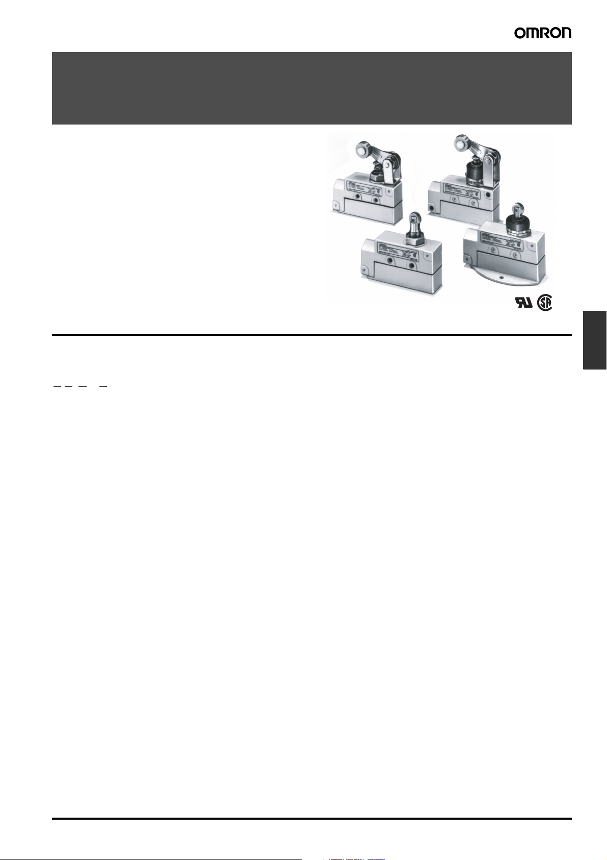
Enclosed Switches
ZE/ZV/XE/XV
Long Service Life and Large Breaking Power
• ZE, ZV, and ZV2 incorporate Model Z Basic Switches with rugged diecast cases.
• Available with various models of built-in switches (including split
contact model, maintained operation type, magnetic blowout
model) and various actuators.
Model Number Structure
■ Model Number Legend
Limit
Switches
@@-@-2@
1
2
3
4
1. Built-in Switch
Z: SPDT (AC)
X: SPDT (DC)
2. Mounting Direction
E: Side mounting
V: Base mounting
V2: Diagonal side mounting
3. Actuator
Q: Plunger
Q22: Roller plunger
Q21: Crossroller plunger
QA2: Roller arm lever
QA277: One-way action roller arm lever
N: Sealed plunger
N22: Sealed roller plunger (ZE, ZV, ZV2 only)
N21: Sealed crossroller plunger (ZE, ZV, ZV2 only)
NA2: Sealed roller arm lever
NA277: Sealed one-way action roller arm lever
4. Conduit/Ground Terminal
None: G
G1: G
G: Pg13.5/with ground terminal
SG1:
YG1: M20/with ground terminal
S:
Y: M20/without ground terminal
1
/2/without ground terminal
1
/2/with ground terminal
1
/2-14NPSM/with ground terminal
1
/2-14NPSM/without ground terminal
Enclosed Switches ZE/ZV/XE/XV F-119
Page 2
Ordering Information
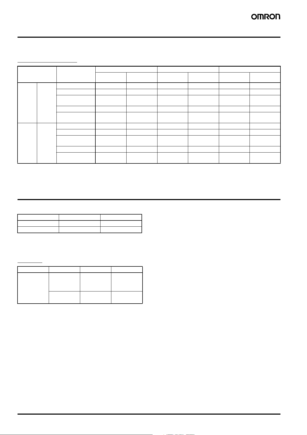
■ List of Models
Standard Switches
Contact Actuator Side mounting Diagonal side mounting Base mounting
General
purpose
AC/DC
load
DC load SPDT Plunger XE-Q-2 XE-N-2 XV2-Q-2 XV2-N-2 XV-Q-2 XV-N-2
Note: 1. The diagonal side mounting model feature improved sealing property, improved mounting strength through use of M5 screws, increased
SPDT Plunger ZE-Q-2 ZE-N-2 ZV2-Q-2 ZV2-N-2 ZV-Q-2 ZV-N-2
Roller plunger ZE-Q22-2 ZE-N22-2 ZV2-Q22-2 ZV2-N22-2 ZV-Q22-2 ZV-N22-2
Crossroller plung-erZE-Q21-2 ZE-N21-2 ZV2-Q21-2 ZV2-N21-2 ZV-Q21-2 ZV-N21-2
Roller arm lever ZE-QA2-2 ZE-NA2-2 ZV2-QA2-2 ZV2-NA2-2 ZV-QA2-2 ZV-NA2-2
One-way action
arm lever
Roller plunger XE-Q22-2 --- XV2-Q22-2 --- XV-Q22-2 ---
Crossroller plung-erXE-Q21-2 --- XV2-Q21-2 --- XV-Q21-2 ---
Roller arm lever XE-QA2-2 XE-NA2-2 XV2-QA2-2 XV2-NA2-2 XV-QA2-2 XV-NA2-2
One-way action
arm lever
stability in seating with large mounting width (31 x 75 mm) and permit coupling of a number of Switch units.
2. ZE, ZV, and ZV2 series are approved by UL and CSA.
ZE-QA277-2 ZE-NA277-2 ZV2-QA277-2 ZV2-NA277-2 ZV-QA277-2 ZV-NA277-2
XE-QA277-2 XE-NA277-2 --- XV2-NA277-2 XV-QA277-2 XV-NA277-2
Sealed
(Booted)
General
purpose
Sealed
(Booted)
General
purpose
Sealed
(Booted)
Specifications
■ Approved Standards
Agency Standard File No.
UL UL508 E76675
CSA CSA C22.2 No. 14 LR45746
Note: Models XE, XV, and XV2 are not approved by UL and CSA.
■ Approved Standard Ratings
UL/CSA
Model Rated voltage Current Horsepower
ZE 125 VAC 15 A 1/8 HP
250 VAC
480 VAC
125 VDC 0.5 A --250 VDC 0.25 A
1/4 HP
F-120 Enclosed Switches ZE/ZV/XE/XV
Page 3
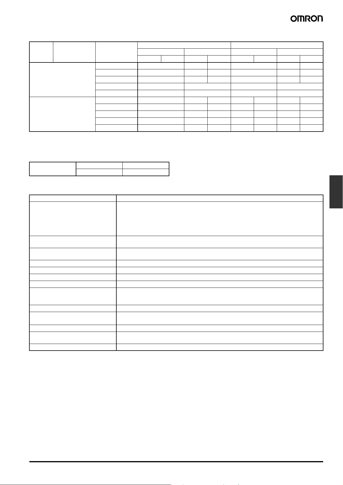
■ Ratings
Contact Contact Rated voltage Non-inductive load Inductive load
Resistive load Lamp load Inductive load Motor load
NC NO NC NO NC NO NC NO
ZE-@
ZV-@
ZV2-@
XE-@
XV-@
XV2-@
Note: 1. The above figures are for standard currents.
2. Inductive loads have a power factor of 0.4 min. (AC) and a time constant of 7 ms max. (DC).
3. Lamp load has an inrush current of 10 times the steady-state current.
4. Motor load has an inrush current of 6 times the steady-state current.
Inrush current NC 30 A max.
NO 15 A max.
125 VAC 15 A 3 A 1.5 A 15 A 5 A 2.5 A
250 VAC 15 A 2.5 A 1.25 A 15 A 3 A 1.5 A
480 VAC 10 A 1.5 A 0.75 A 6 A 1.5 A 0.75 A
125 VDC 0.5 A 0.5 A 0.05 A 0.05 A
250 VDC 0.25 A 0.25 A 0.03 A 0.03 A
8 VDC 15 A 3 A 3 A 15 A 15 A 10 A 10 A
14 VDC 15 A 3 A 3 A 15 A 10 A 10 A 10 A
30 VDC 15 A 3 A 3 A 10 A 10 A 10 A 6 A
125 VDC 10 A 3 A 1.5 A 7.5 A 6 A 6 A 4 A
250 VDC 3 A 1.5 A 0.75 A 2 A 1.5 A 2 A 1 A
■ Characteristics
Degree of protection IP65 (see note 2)
Durability (see note 3) Mechanical:
Operating speed Plunger type: 0.01 mm to 0.5 m/s
Operating frequency Mechanical: 120 operations/min
Rated frequency 50/60 Hz
Insulation resistance 100 MΩ min. (at 500 VDC)
Contact resistance 15 mΩ max. (initial value)
Terminal temperature rise 50° max.
Dielectric strength 1,000 VAC, 50/60 Hz for 1 min between terminals of the same polarity
Vibration resistance Malfunction: 10 to 55 Hz, 1.5-mm double amplitude (see note 4)
Shock resistance (see note 4)
Ambient temperature (see note 1) Operating: –10°C to 80°C (with no icing)
Ambient humidity Operating: General-purpose type: 85% max.
Weight Approx. 260 to 280 g
Note: 1. The above figures are initial values.
2. IP65 for @E-N models and IP60 for @E-Q models.
3. The values are calculated at an operating temperature of 5°C to 35°C, and an operating humidity of 40% to 70%. Contact your OMRON
sales representative for more detailed information on other operating environments.
4. At the operation limit positions.
5. Only for plunger, sealed plunger, roller arm lever, and sealed roller arm lever.
6. Only for crossroller plunger, sealed crossroller plunger, roller plunger, and sealed roller plunger.
Z@: 10,000,000 operations min.
X@: 1,000,000 operations min.
Electrical:
Z@: 500,000 operations min., for 15 A, 250 VAC resistive load
X@: 100,000 operations min., for 10 A, 125 VDC resistive load
Lever type: 0.02 mm to 0.5 m/s
Electrical: 20 operations/min
2,000 VAC, 50/60 Hz for 1 min between current-carrying metal part and ground, and between each
terminal and non-current-carrying metal part (1,500 VAC for Z@ models and X@ models)
2
Destruction: 1,000 m/s
Malfunction: 100 m/s
Sealed type: 95% max.
min.
2
min. (see note 5), 50 m/s2 min. (see note 6)
Limit
Switches
Enclosed Switches ZE/ZV/XE/XV F-121
Page 4
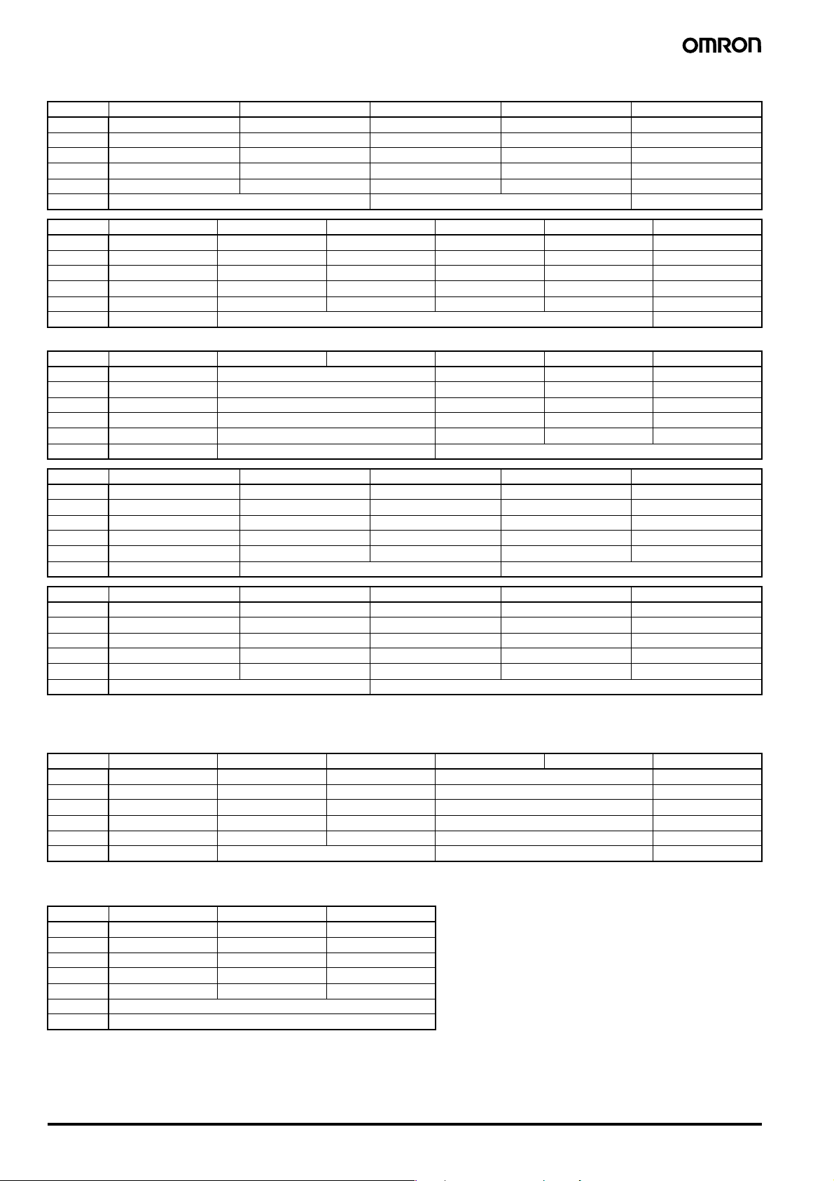
■ Operating Characteristics
Model ZE-Q-2 XE-Q-2 ZE-Q22-2 XE-Q22-2 ZE-Q21-2
OF 2.45 to 3.43 N 5.00 N max. 2.45 to 3.43 N 5.00 N max. 2.45 to 3.43 N
RF min. 1.12 N 1.12 N 1.12 N 1.12 N 1.12 N
PT max. 0.4 mm 0.9 mm 0.5 mm 0.9 mm 0.5 mm
OT min. 5.5 mm 5.5 mm 3.6 mm 3.6 mm 3.6 mm
MD max. 0.05 mm 0.47 mm 0.05 mm 0.47 mm 0.05 mm
OP 38.2±0.8 mm 49.7±1 mm 49.7±1 mm
Model XE-Q21-2 ZE-QA2-2 XE-QA2-2 ZE-QA277-2 XE-QA277-2 ZE-N-2
OF 5.00 N max. 5.59 N max. 6.47N max. 5.59 N 6.47 N 7.85 N
RF min. 1.12 N 1.67 N 1.67 N 1.67 N 1.67 N 2.35 N
PT max. 0.9 mm 4 mm 6 mm 4 mm 6 mm 2 mm
OT min. 3.6 mm 6 mm 5.5 mm 6 mm 5.5 mm 5 mm
MD max. 0.47 mm 0.4 mm 0.72 mm 0.4 mm 0.72 mm 0.1 mm
OP 49.7±1 mm --- 45.8±0.8 mm
Model XE-N-2 ZE-N22-2 ZE-N21-2 ZE-NA2-2 XE-NA2-2 ZE-NA277-2
OF 10.20 N 4.90 N 6.28 N 7.26 N 6.28 N
RF min. 2.35 N 0.98 N 2.26 N 2.26 N 2.26 N
PT max. 3 mm 1 mm 5 mm 6 mm 5 mm
OT min. 4 mm 3.5 mm 6 mm 5.5 mm 6 mm
MD max. 0.47 mm 0.12 mm 0.4 mm 0.72 mm 0.4 mm
OP 45.8±0.8 mm 49.7±0.8 mm ---
Model XE-NA277-2 ZV(2)-Q-2 XV(2)-Q-2 ZV(2)-Q22-2 XV(2)-Q22-2
OF 7.26 N 2.45 to 3.43 N 5.00 N max. 2.45 to 3.43 N 5.00 N max.
RF min. 2.26 N 1.12 N 1.12 N 1.12 N 1.12 N
PT max. 6 mm 0.4 mm 0.9 mm 0.5 mm 0.9 mm
OT min. 5.5 mm 5.5 mm 5.5 mm 3.6 mm 3.6 mm
MD max. 0.72 mm 0.05 mm 0.47 mm 0.05 mm 0.47 mm
OP --- 63.7±0.8 mm (ZV-Q-2, XV-Q-2) (see note 1) 75.2±0.8 mm (ZV-Q-22.2, XV-Q21-2) (see note 2)
Model ZV(2)-Q21-2 XV(2)-Q21-2 ZV(2)-QA2-2 XV(2)-QA2-2 ZV(2)-QA277-2
OF 2.45 to 3.43 N 5.00 N max. 5.59 N max. 6.47 N max. 5.59 N
RF min. 1.12 N 1.12 N 1.67 N 1.67 N 1.67 N
PT max. 0.5 mm 0.9 mm 4 mm 6 mm 4 mm
OT min. 3.6 mm 3.6 mm 6 mm 5.5 mm 6 mm
MD max. 0.05 mm 0.47 mm 0.4 mm 0.72 mm 0.4 mm
OP 75.2±0.8 mm (ZV-Q22-2, XV-Q21-2) (see note 3) ---
Note: 1. The OP of ZV2-Q-2/XV2-Q-2 is 24.2±0.8 mm.
2. The OP of ZV2-Q22-2/XV2-Q22-2 is 35.7±1 mm.
3. The OP of ZV2-Q21-2/XV2-Q21-2 is 35.7±0.8 mm.
Model XV(2)-QA277-2 ZV(2)-N-2 XV(2)-N-2 ZV(2)-N22-2 ZV(2)-N21-2 ZV(2)-NA2-2
OF 6.47 N 7.85 N 10.20 N 4.90 N 6.28 N
RF min. 1.67 N 2.35 N 2.35 N 0.98 N 2.26 N
PT max. 6 mm 2 mm 3 mm 1 mm 5 mm
OT min. 5.5 mm 5 mm 4 mm 3.5 mm 6 mm
MD max. 0.72 mm 0.1 mm 0.47 mm 0.12 mm 0.4 mm
OP --- 71.4±0.8 mm (ZV-N-2, XV-N-2) (see note 1) 75.2±0.8 mm (ZV-N22-2, ZV-N21-2) (see note 2) ---
Note: 1. The OP of ZV2-N-2/XV2-N-2 is 31.9±0.8 mm.
2. The OP of ZV2-N22-2/ZV2-N21-2 is 35.7±0.8 mm.
Model XV(2)-NA2-2 ZV(2)-NA277-2 XV(2)-NA277-2
OF 7.26 N 6.28 N 7.26 N
RF min. 2.26 N 2.26 N 2.26 N
PT max. 6 mm 5 mm 6 mm
OT min. 5.5 mm 6 mm 5.5 mm
MD max. 0.72 mm 0.4 mm 0.72 mm
FP max. --OP ---
F-122 Enclosed Switches ZE/ZV/XE/XV
Page 5
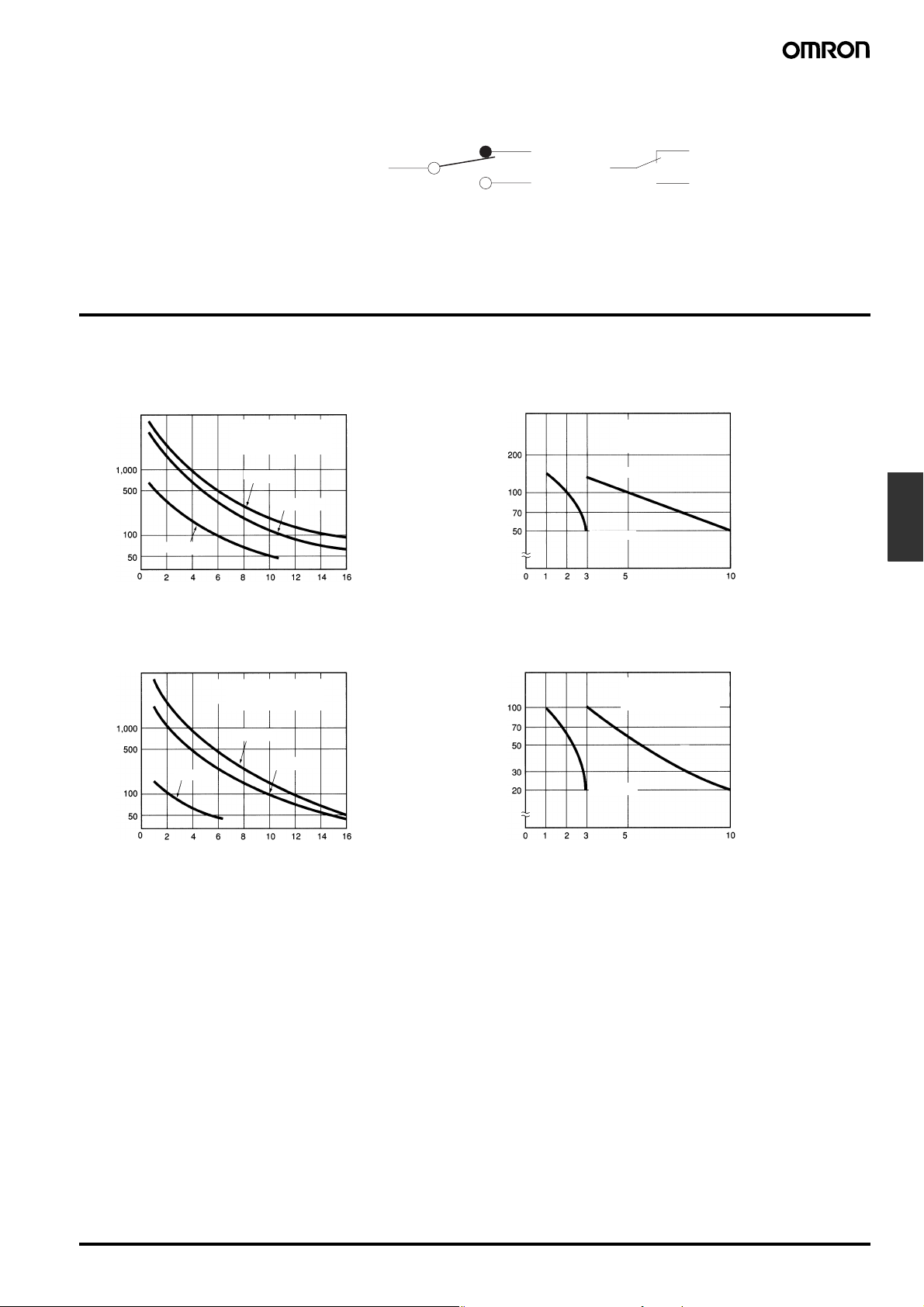
■ Contact Form
O
ZE-@, ZV-@, ZV2-@
XE-@, XV-@, XV2-@
Engineering Data
■ Electrical Durability
NC
COM
Note: With the XE-@, XV-@, and
XV2-@, be sure to connect
COM to the + terminal.
NO
NC
COM
N
EN60947-5-1
ZE (cosφ = 1)
operations)
4
480 VAC
Durability (x 10
ZE (cosφ = 0.4)
operations)
4
480 VAC
Durability (x 10
Operating frequency:
20 operations/min
OT: Full stroke
125 VAC
250 VAC
Switching current (A)
Operating frequency:
20 operations/min
OT: Full stroke
125 VAC
250 VAC
XE (L/R = 0)
operations)
4
Durability (x 10
Switching current (A)
XE (L/R = 7 ms)
operations)
4
Durability (x 10
Operating frequency:
20 operations/min
OT: Full stroke
125 VDC
250 VDC
Operating frequency:
20 operations/min
OT: Full stroke
125 VDC
250 VDC
Limit
Switches
Switching current (A)
Switching current (A)
Enclosed Switches ZE/ZV/XE/XV F-123
Page 6
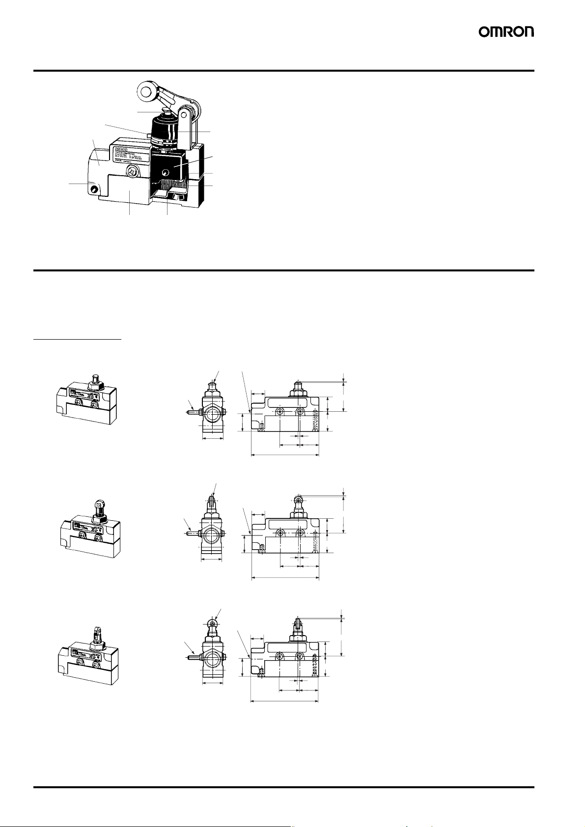
Nomenclature
Pin plunger
Tightening band
Conduit
opening
Case
Seal rubber (NBR)Cover
Rubber cap (CR)
Separator
Built-in switch
Terminal
Dimensions
Note: 1. All units are in millimeters unless otherwise indicated.
2. Unless otherwise specified, a tolerance of ±0.4 mm applies to all dimensions.
3. In the drawings for the Base Mounting Type Switches (ZV), the mounting surfaces (flanges) are shown by lines of alternate long and two
short dashes.
Side Mounting
Plunger
ZE-Q-2, XE-Q-2
Roller Plunger
ZE-Q22-2, XE-Q22-2
Crossroller Plunger
ZE-Q21-2, XE-Q21-2
Two, M4
(length: 45)
Two, M4
(length: 45)
Two, M4
(length: 45)
12R
(see note)
25.4±0.3
25.4±0.3
12.7 dia. × 4.8 (see note)
JIS B0202 G1/2
Effective thread: 4 threads min.
23
12.7 dia. × 4.8 (see note)
JIS B0202 G1/2
Effective thread:
4 threads min.
23
JIS B0202 G1/2
Effective thread:
4 threads min.
17
17
17
2.1
±0.1
25.4
±0.12
86
2.1
±0.1
25.4±0.12
86
PT
OP
19
25.5
24
PT
OP
19
25.5
24
PT
OP
19
Note: Stainless steel plunger
Note: Stainless steel roller
23
25.4±0.3
F-124 Enclosed Switches ZE/ZV/XE/XV
2.1
±0.1
25.4±0.12
86
25.5
24
Note: Stainless steel roller
Page 7
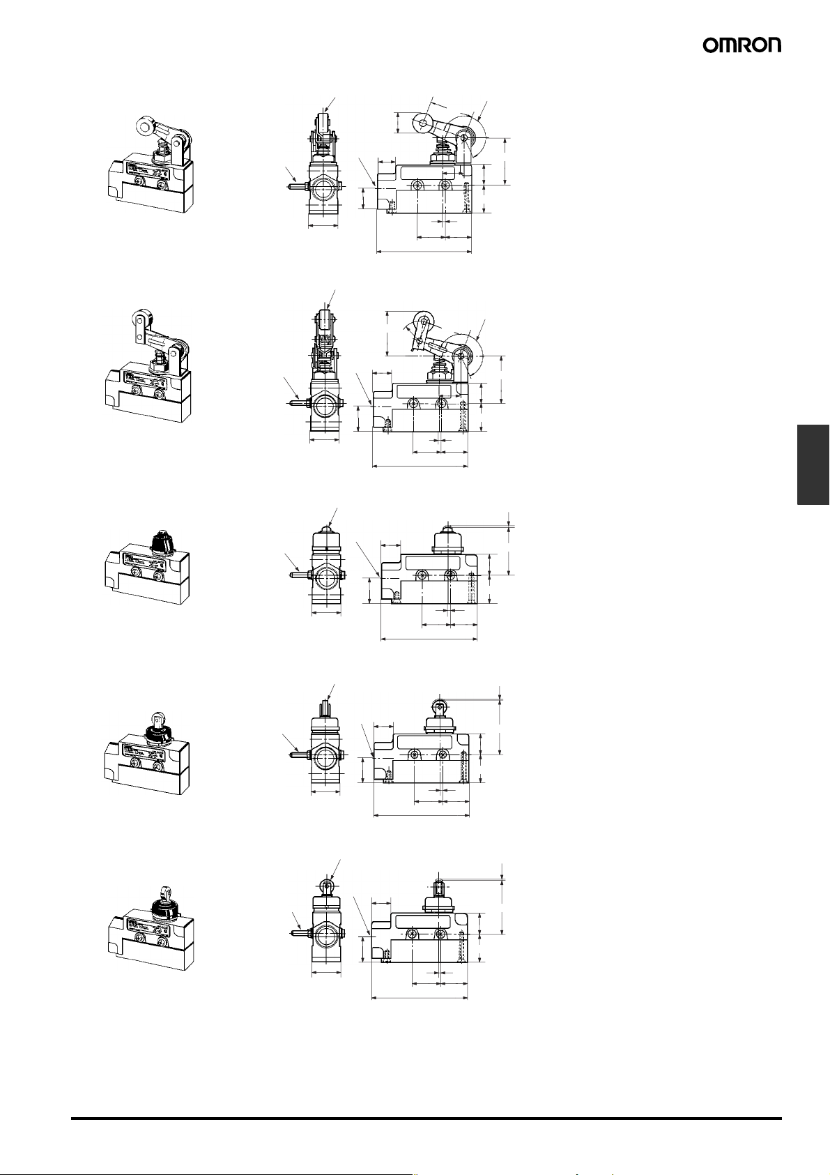
Roller Arm Lever
ZE-QA2-2, XE-QA2-2
Two, M4
(length: 45)
19.1 dia. × 7.9 (see note 1)
(23.1)
JIS B0202 G1/2
Effective thread:
4 threads min.
17
19.3
(See note 2)
39.7
44±0.8
19
One-way Action Roller Arm Lever
ZE-QA277-2, XE-QA277-2
Two, M4
(length: 45)
Sealed Plunger
ZE-N-2, XE-N-2
Two, M4
(length: 45)
23
25.4±0.3
18.7 dia. × 9 (see note 1)
(40)
JIS B0202
G1/2
Effective
thread: 4
threads min.
17
23
25.4±0.3
12R (see note)
JIS B0202 G1/2
Effective thread:
4 threads min.
17
23
25.4±0.3
2.1
±0.1
24
25.4±0.12
86
← Operate in this direction only
2.1
±0.1
86
2.1
±0.1
25.4±0.12
86
39.7
19.3
24
24
17.4R
17.4R
25.4±0.12
25.5
(See note 2)
44±0.8
19
25.5
PT
OP
19
25.5
Note: 1. Stainless sintered roller
2. Adjustable between 0° and 225°
Note: 1. Stainless sintered alloy roller
2. Adjustable between 0° and 225°
Note: Stainless steel plunger
Limit
Switches
Sealed Roller Plunger
ZE-N22-2
Sealed Crossroller Plunger
ZE-N21-2
Two, M4
(length: 45)
Two, M4
(length: 45)
12.7 dia. × 4.8 (see note)
JIS B0202 G1/2
Effective thread:
4 threads min.
17
23
25.4±0.3
12.7 dia. × 4.8 (see note)
JIS B0202 G1/2
Effective thread:
4 threads min.
17
23
25.4±0.3
2.1
±0.1
25.4±0.12
86
2.1
±0.1
25.4±0.12
86
PT
OP
19
25.5
24
PT
OP
19
25.5
24
Note: Stainless steel roller
Note: Stainless steel roller
Enclosed Switches ZE/ZV/XE/XV F-125
Page 8
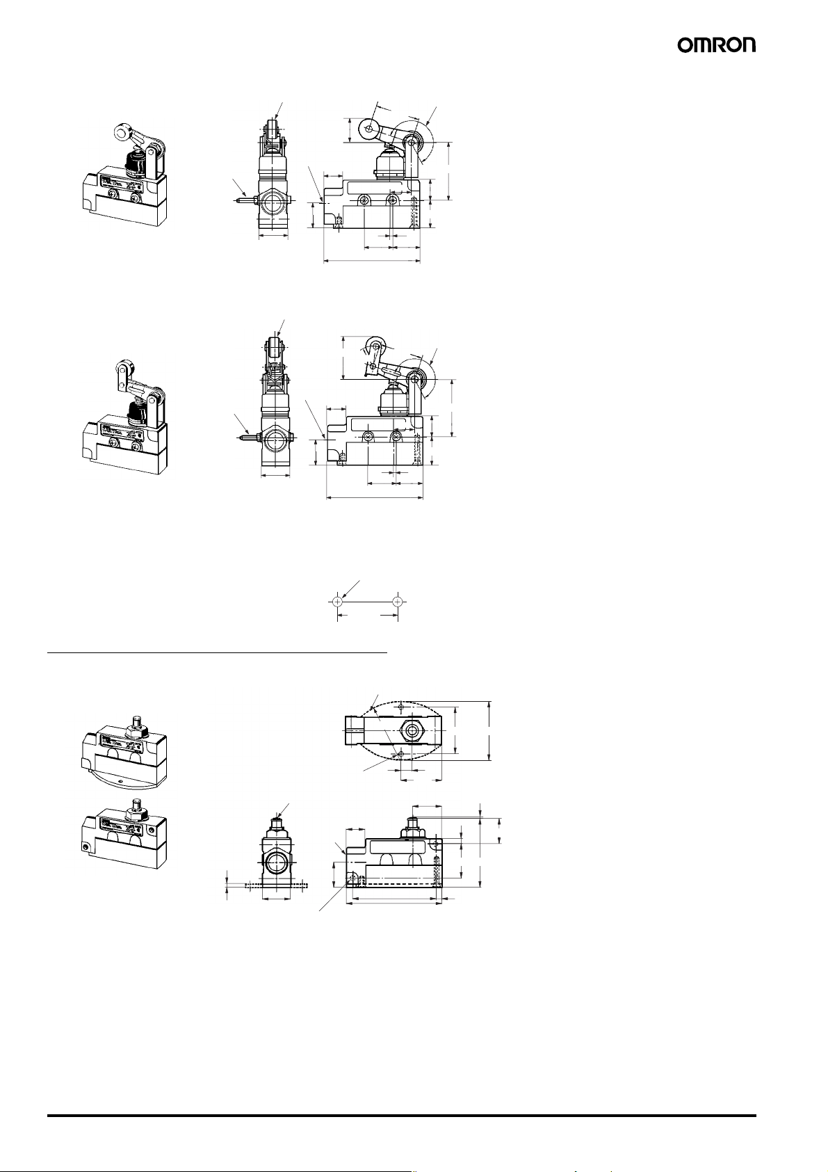
Sealed Roller Arm Lever
ZE-NA2-2, XE-NA2-2
Two, M4
(length: 45)
19.1 dia. × 7.9 (see note 1)
25.4±0.3
One-way Action Sealed Roller Arm Lever
ZE-NA277-2, XE-NA277-2
18.7 dia. × 9 (see note 1)
(23.1)
JIS B0202
G1/2
Effective thread:
4 threads min.
17
23
(See note 2)
39.7
53.4±0.8
19
19.3
25.5
2.1
±0.1
25.4±0.12
24
86
← Operates in this direction only
Note: 1. Stainless steel roller
2. Adjustable between 0° and 225°
(40)
17.4R
17
2.1
±0.12
25.4±0.12
86
Two, M4
(length: 45)
25.4±0.3
JIS B0202
G1/2
Effective thread:
4 threads min.
23
Mounting Hole
Two, 4.3 dia.
mounting holes or
M4 screw holes
25.4±0.1
Base Mounting/Diagonal Side Mounting
Plunger
ZV(2)-Q-2, XV(2)-Q-2
t = 3 (ZV-Q-2/XV-Q-2 flange)
53R
39.7
19.3
24
(See note 2)
53.4±0.8
19
25.5
41.3±0.2
Note: 1. Stainless steel roller
2. Adjustable between 0° and 225°
54
Two, 4.3±0.2 dia. holes
12R (see note 1.)
JIS B0202
G1/2 Effective
thread: 4
threads min.
3
25.4±0.3
Two, 5.4
23
+0.2
−0
dia. holes (see note 2)
F-126 Enclosed Switches ZE/ZV/XE/XV
10.5±0.3
36.6
5
31±0.2
5.5
PT
OP (see note 3)
OP (see note 4)
Note: 1. Stainless steel plunger
2. Only the ZV2-Q-2 and
XV2-Q-2 incorporate
mounting holes.
3. OP for ZV2-Q-2 and
XV2-Q-2 is 24.2 ±0.8 mm.
26.1
17
75±0.2
86
Page 9
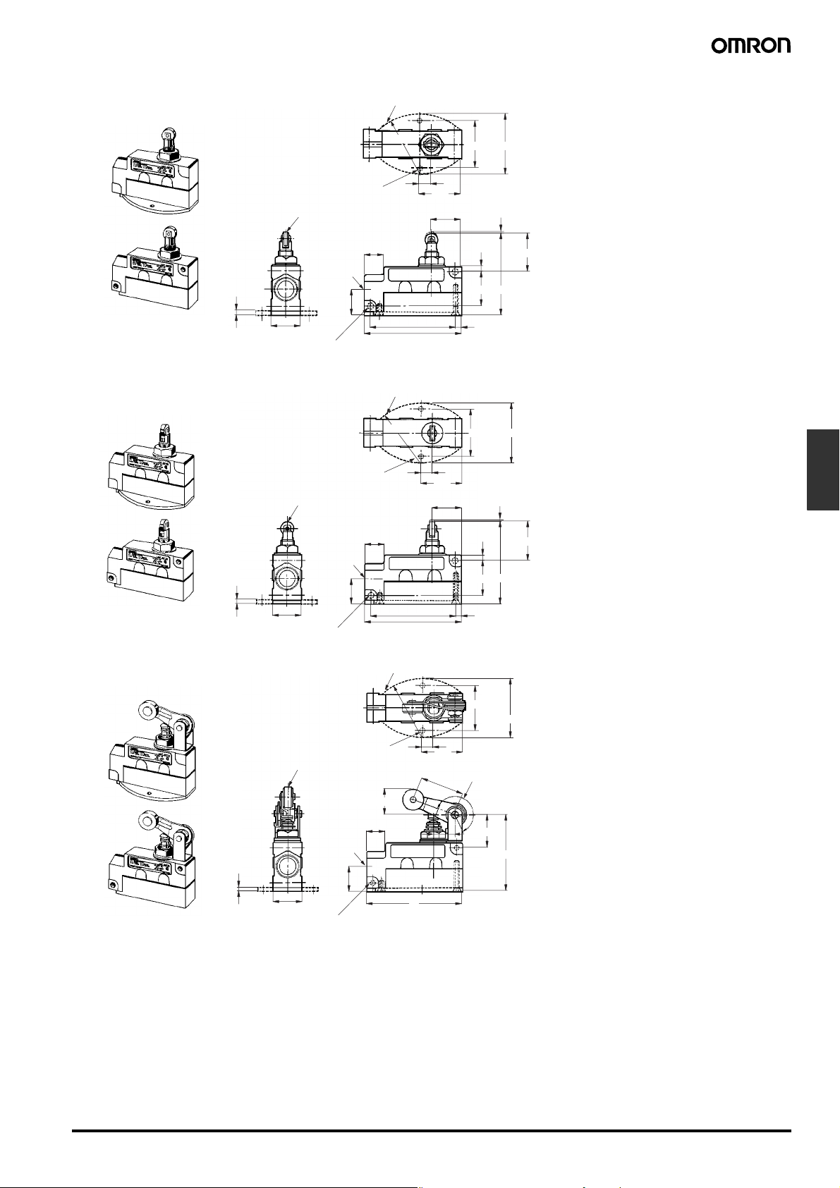
Roller Plunger
ZV(2)-Q22-2, XV(2)-Q22-2
t = 3 (ZV-Q22-2/XV-Q22-2 flange)
Crossroller Plunger
ZV(2)-Q21-2, XV(2)-Q21-2
53R
10.5±0.3
Two, 4.3±0.2 dia. holes
12.7 dia. × 4.8 (see note 1)
JIS B0202 G1/2
Effective thread:
4 threads min.
3
25.4±0.3
Two, 5.4
+0.2
−0
17
23
dia. holes (see note 2)
36.6
26.1
75±0.2
86
41.3±0.2
5
31±0.2
31±0.2
5.5
54
PT
OP (see note 3)
OP (see note 4)
Note: 1. Stainless steel roller
2. Only the ZV2-Q22-2 and
XV2-Q22-2 incorporate mounting holes.
3. OP for ZV2-Q22-2 and
XV2-Q22-2 is 35.7 ±1 mm.
t = 3 (ZV-Q21-2/XV-Q21-2 flange)
53R
Two, 4.3±0.2 dia. holes
12.7 dia. × 4.8 (see note 1)
JIS B0202
G1/2
Effective
thread: 4
threads min.
3
25.4±0.3
Two, 5.4
+0.2
−0
17
23
dia. holes (see note 2)
10.5±0.3
36.6
26.1
75±0.2
86
41.3±0.2
5
31±0.2
5.5
54
PT
OP (see note 3)
OP (see note 4)
Note: 1. Stainless steel roller
2. Only the ZV2-Q21-2 and XV2-Q21-2
incorporate mounting holes.
3. OP for ZV2-Q21-2 and XV2-Q21-2 is
35.7 ±0.8 mm.
Limit
Switches
Roller Arm Lever
ZV(2)-QA2-2, XV(2)-QA2-2
t = 3 (ZV-QA2-2/XV-QA2-2 flange)
53R
Two, 4.3±0.2 dia. holes
19.1 dia. × 7.9 (see note 1)
23.1 max.
JIS B0202
G1/2
Effective
thread: 4
threads min.
3
25.4±0.3
Two, 5.4
23.1 max.
17
23
+0.2
dia. holes (see note 3)
−0
19.3
86
10.5±0.3
36.6
39.7
41.3±0.2
(See note 2)
30±0.8
69.5±0.8
54
Note: 1. Stainless sintered alloy roller
2. Adjustment between 0° to 225°.
3. Only the ZV2-QA2-2 and XV2-QA2-2
incorporate mounting holes.
Enclosed Switches ZE/ZV/XE/XV F-127
Page 10
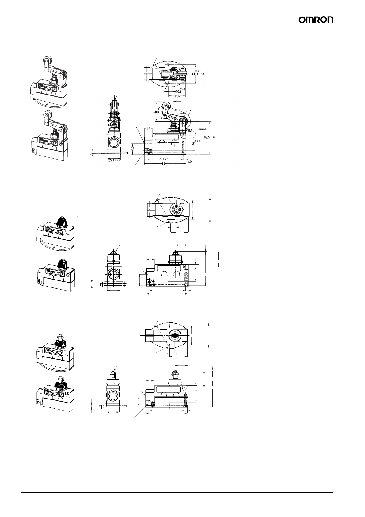
One-way Action Roller Arm Lever
ZV(2)-QA277-2, XV(2)-QA277-2
t = 3 (ZV-QA277-2/XV-QA277-2 flanges)
53R
Sealed Plunger
ZV(2)-N-2, XV(2)-N-2
18.7 dia. × 9 (see note 1)
+0.2
−0
Two, 5.4
dia. holes (see note 3)
12CR (see note 1)
3
25.4±0.3
Two, 5.4
Two, 4.3±0.2 dia. holes
JIS B0202
G1/2
Effective
thread: 4
threads min.
t = 3 (ZV-N-2/XV-N-2 flange)
Two, 4.3±0.2 dia. holes
JIS B0202
G1/2
Effective
thread: 4
threads min.
17
23
+0.2
−0
dia. holes (see note 2)
53R
75±0.2
86
Operates in this direction only
(See note 2)
54
41.3±0.2
10.6±0.3
36.6
26.1
PT
PT
5
31±0.2
OP (see note 4)
5.5
Note: 1. Stainless steel roller
2. Adjustment between 0° to 225°.
3. Only the ZV2-QA277-2 and
XV2-QA277-2 incorporate mounting
holes.
OP (see note 3)
Note: 1. Stainless steel plunger
2. Only the ZV2-N-2 and XV2-N-2
incorporate mounting holes.
3. OP for ZV2-N-2 and XV2-N-2 is
31.9 ±0.8 mm.
Sealed Roller Plunger
ZV(2)-N22-2
t = 3 (ZV-N22-2 flange)
Two, 4.3±0.2 dia. holes
12.7 dia. × 4.8 (see note 1)
JIS B0202
G1/2
Effective
thread: 4
threads min.
17
53R
10.6±0.3
36.6
26.1
41.3±0.2
5
54
PT
OP (see note 3)
OP (see note 4)
Note: 1. Stainless steel roller
2. Only the ZV2-N22-2 incorpo incorpo-
rate mounting holes.
3. OP for ZV2-N22-2 is 35.7 ±0.8 mm.
31±0.2
23
3
25.4±0.3
Two, 5.4
+0.2
−0
dia. holes (see note 2)
75±0.2
86
5.5
F-128 Enclosed Switches ZE/ZV/XE/XV
Page 11
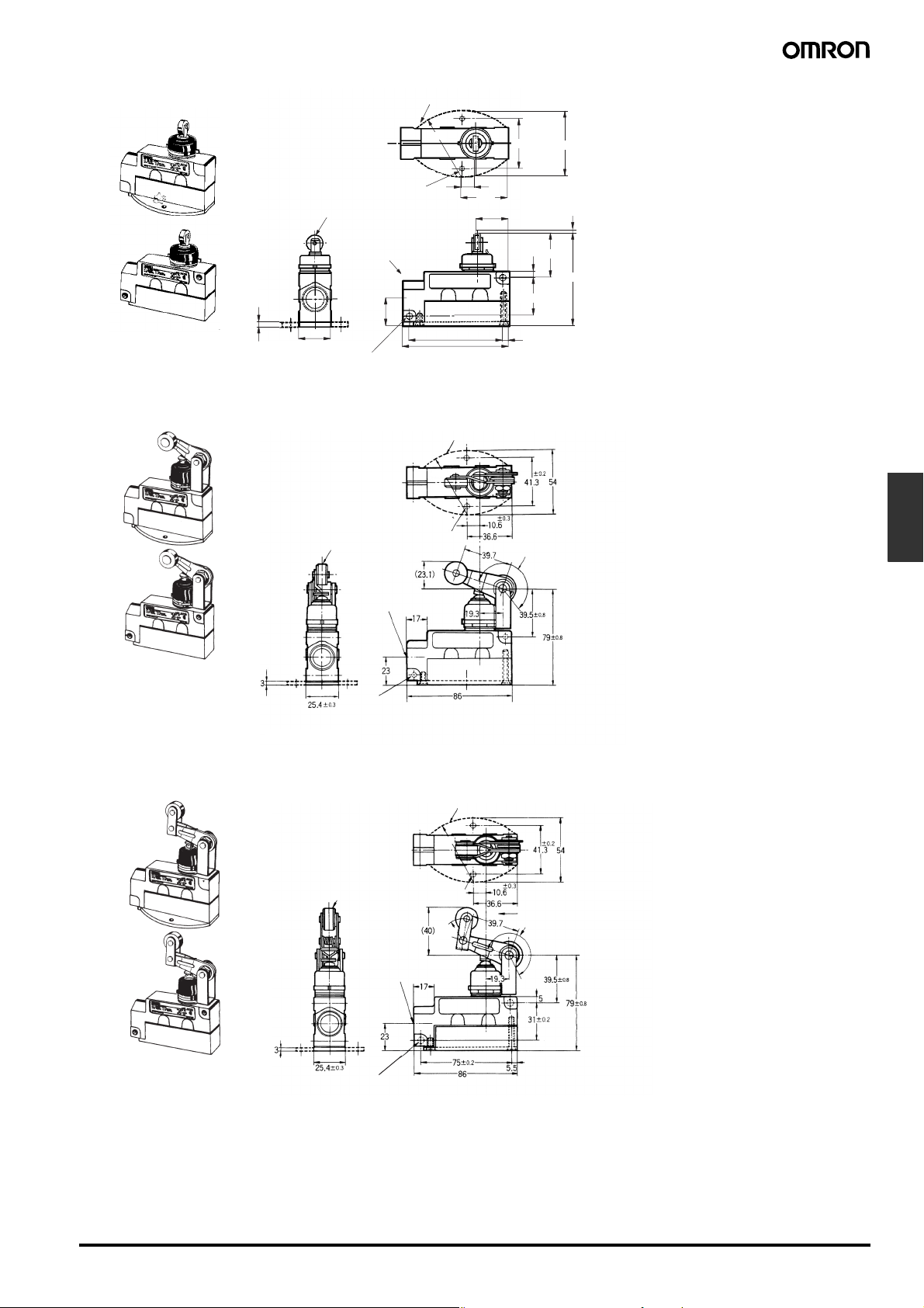
Sealed Crossroller Plunger
ZV(2)-N21-2
t = 3 (ZV flange)
53R
41.3±0.2
54
Sealed Roller Arm Lever
ZV(2)-NA2-2, XV(2)-NA2-2
12.7 dia. × 4.8 (see note 1)
3
25.4±0.3
Two, 5.4
19.1 dia. × 7.9 (see note 1)
Two, 4.3±0.2 dia. holes
JIS B0202 G1/2
Effective thread: 4
threads min.
23
+0.2
−0
dia. holes (see note 2)
t=3 (ZV-NA2-2/XV-NA2-2 flanges)
53R
Two, 4.3±0.2 dia.
JIS B0202 G1/2
Effective thread:
4 threads min.
75±0.2
86
10.6±0.3
36.6
26.1
OP (see note 3)
5
31±0.2
5.5
(See note 2)
PT
PT
OP (see note 4)
Note: 1. Stainless steel roller
Note: 1. Stainless steel roller
2. Only the ZV2-N21-2 in-
corporate mounting holes.
3. OP for ZV2-N21-2 is 35.7
±0.8 mm.
2. Adjustment between 0° to 225°.
3. Only the ZV2-NA2-2 and XV2-NA2-2
incorporate mounting holes.
Limit
Switches
One-way Action Sealed Roller Arm Lever
ZV(2)-NA277-2, XV(2)-NA277-2
18.7 dia. × 9 (see note 1)
+0.2
−0
Two, 5.4
dia. holes (see note 3)
Two, 5.4
JIS B0202
G1/2
Effective
thread: 4
threads min.
+0.2
−0
dia. holes (see note 3)
t=3 (ZV-NA277-2/XV-NA277-2 flanges)
53R
Tw o,
4.3±0.2 dia.
17.4R
Operates in this direction only
(See note 2)
Note: 1. Stainless steel roller
2. Adjustment between 0° to 225°.
3. Only the ZV2-NA277-2 and
XV2-NA277-2 incorporate mounting
holes.
Enclosed Switches ZE/ZV/XE/XV F-129
Page 12
Precautions
■ Correct Use
Mounting
With the Roller Lever-type Enclosed Switches, the roller arm has
been temporarily tightened prior to shipment, so that its position may
be adjusted later. When mounting the Switch, be sure to re-tighten
the roller arm so as to prevent it from becoming loose during operation.
To adequately maintain the seals at the mounting screw section on
the side of the Enclosed Switch, insert each O-ring correctly and
secure it with the lock nut.
To provide the Switch with improved sealing property, use of the SC
Connector is recommended.
When routing wires into the conduit opening, be sure that cuttings
and other foreign matter do not enter the Switch.
Environmental Precautions
Sealing materials may deteriorate when used outdoors or when
exposed to cutting oil, solvents, or chemicals. Check this on actual
equipment and, if deterioration is foreseen, consult your OMRON
representative in advance.
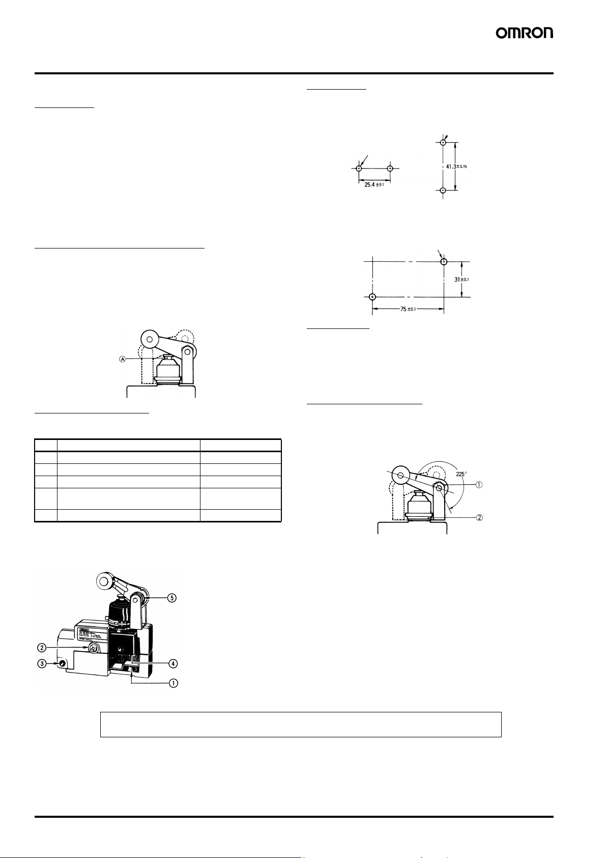
Be sure to protect part A with grease in order to maintain the
mechanical life and performance of the Limit Switch. The use of
molybdenum disulfide grease is recommended.
Tightening Torque
A loose screw may result in a malfunction. Be sure to tighten each
screw to the proper tightening torque as shown below.
No. Type Torque
1 Cover mounting screw 1.18 to 1.37 N·m
2 Switch mounting screw (see note 1) 1.18 to 1.37 N·m
3 Switch mounting screw (see note 2) 4.90 to 5.88 N·m
4 Switch terminal screw (M4 screws for
head)
5 Roller arm mounting nut 4.90 to 5.88 N·m
Note: 1. This torque range applies to side mounting or bottom
mounting. (M4 screws for head)
2. This torque range applies to side diagonal mounting. (M5
Allen-head bolt)
0.78 to 1.18 N·m
Mounting
Mounting Holes
Side Mounting Bottom Mounting
Two, 4.3 dia.
mounting holes or
M4 screw holes
Side Diagonal Mounting
Two, 5.4 dia.
mounting holes or
M5 screw holes
Two, 4.3 dia.
mounting holes or
M4 screw holes
Operation
• Operating method, shape of cam or dog, operating frequency, and
the overtravel (OT) have significant effect on the service life and
precision of the Limit Switch. Make sure that the shape of the cam
is smooth enough.
• Check that OT has a sufficient margin. The actual OT should be
rated OT x 0.7 to 1.
Dedicated Wrench
The roller arm can be set freely within a range of 225° after loosening
the nut.
The roller arm mounting bracket can be set in any direction after
loosening the nut.
A dedicated wrench is provided separately.
Model: SUPANA FOR ZE
Make sure that the nut is free of foreign substances when the nut is
loosened.
ALL DIMENSIONS SHOWN ARE IN MILLIMETERS.
To convert millimeters into inches, multiply by 0.03937. To convert grams into ounces, multiply by 0.03527.
Cat. No. C020-E1-09
In the interest of product improvement, specifications are subject to change without notice.
F-130 Enclosed Switches ZE/ZV/XE/XV
 Loading...