

Page 1
General-purpose Basic Switch X F-149
Limit
Switches
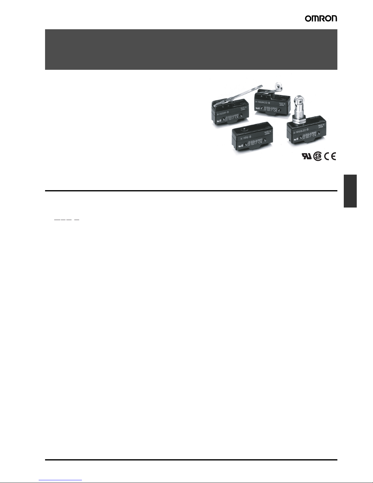
General-purpose Basic Switch
X
Direct Current Switch with Built-in Magnetic
Blowout
• Incorporates a small permanent magnet in the contact mechanism to deflect the arc to effectively extinguish it.
• Same shape and mounting procedures as the Z Basic Switches.
Model Number Structure
■ Model Number Legend
1. Ratings
10: 10 A (125 VDC)
2. Contact Gap
G: 0.9 mm
3. Actuator
None: Pin plunger
D: Short spring plunger
S: Slim spring plunger
Q: Panel mount plunger
Q21: Panel mount cross roller plunger
Q22: Panel mount roller plunger
L: Leaf spring
W: Hinge lever
W2: Hinge roller lever
W21: Short hinge lever
W22: Short hinge roller lever
W4: Low-force hinge lever
M: Reverse hinge lever
M2: Reverse hinge roller lever
M22: Reverse short hinge roller lever
4. Terminals
None: Solder terminal
B: Screw terminal (with toothed washer)
1 2 3 4
X-10G@-@
Page 2
F-150 General-purpose Basic Switch X
Ordering Information
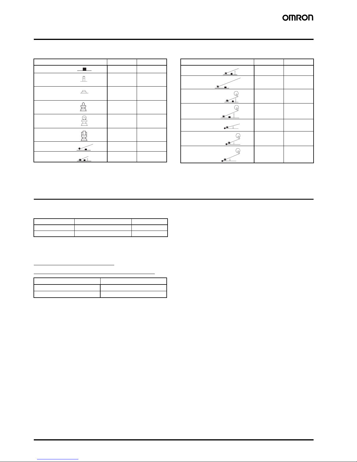
■ List of Models
Note: The plungers of reverse-type models are continuously pressed by the compression coil springs and the plungers are freed by operating the
levers.
Specifications
■ Approved Standards
■ Approved Standard Ratings
UL508 (File No. E41515)
CSA C22.2 No.55 (File No. LR21642)
Actuator Solder Screw
X-10G X-10G-B
X-10GS X-10GS-B
X-10GD X-10GD-B
X-10GQ X-10GQ-B
X-10GQ22 X-10GQ22-B
X-10GQ21 X-10GQ21-B
X-10GL X-10GL-B
X-10GW21 X-10GW21-B
Pin plunger
Slim spring
plunger
Short spring
plunger
Panel mount
plunger
Panel mount
roller plunger
Panel mount cross
roller plunger
Leaf spring
Short hinge lever
Actuator Solder Screw
X-10GW X-10GW-B
X-10GW4 X-10GW4-B
X-10GW22 X-10GW22-B
X-10GW2 X-10GW2-B
X-10GM X-10GM-B
X-10GM22 X-10GM22-B
X-10GM2 X-10GM2-B
Hinge lever
Low-force hinge
lever
Short hinge roller
lever
Hinge roller lever
Reverse hinge
lever
Reverse short
hinge roller lever
Reverse hinge
roller lever
Agency Standard File No.
UL UL508 E41515
CSA CSA C22.2 No. 55 LR21642
Rated voltage X-10G
125 VDC 10 A
250 VDC 3 A
Page 3

General-purpose Basic Switch X F-151
Limit
Switches
■ Ratings
Note: 1. The above values are for the steady-state current.
2. Inductive load has a power factor of 0.4 min. (AC) and a time constant of 7 ms max. (DC).
3. Lamp load has an inrush current of 10 times the steady-state current.
4. Motor load has an inrush current of 6 times the steady-state current.
5. The above electrical ratings also apply to the AC voltage.
6. With the reverse-type models (X-10GM@), the normally closed circuits and normally open circuits are reversed.
7. The ratings values apply under the following test conditions:
Ambient temperature: 20±2°C
Ambient humidity: 65±5%
Operating frequency: 20 operations/min
■ Characteristics
Note: 1. The values are for the pin plunger models. (Contact your OMRON representative for other models.)
2. Malfunction: 1 ms max.
■ Contact Specification ■ Contact Form (SPDT)
Note: With the reverse-type models (X-10GM@), the NC and NO ter-
minal arrangements are reversed.
Rated voltage Non-inductive load Inductive load
Resistive load Lamp load Inductive load Motor load
NC NO NC NO NC NO
8 VDC
14 VDC
30 VDC
125 VDC
250 VDC
10 A
10 A
10 A
10 A
3 A
3 A
3 A
3 A
3 A
1.5 A
1.5 A
1.5 A
1.5 A
1.5 A
0.75 A
10 A
10 A
10 A
7.5 A
2 A
10 A
10 A
10 A
6 A
1.5 A
5 A
5 A
5 A
5 A
2 A
2.5 A
2.5 A
2.5 A
2.5 A
1.5 A
Operating speed 0.1 mm to 1 m/s (see note 1)
Operating frequency Mechanical: 240 operations/min
Electrical: 20 operations/min
Insulation resistance 100 MΩ min. (at 500 VDC)
Contact resistance 15 mΩ max. (initial value)
Dielectric strength 1,500 VAC, 50/60 Hz for 1 min between terminals of the same polarity, between current-carrying metal parts and
the ground, and between each terminal and non-current-carrying metal parts
Vibration resistance Malfunction: 10 to 55 Hz, 1.5-mm double amplitude (see note 2)
Shock resistance
Destruction: 1,000 m/s
2
{approx. 100G} max.
Malfunction: 300 m/s
2
{approx. 30G} max. (see note 1, 2)
Durability Mechanical: 1,000,000 operations min.
Electrical: 100,000 operations min.
Degree of protection IP00
Degree of protection against
electric shock
Class I
Proof tracking index (PTI) 175
Switch category D (IEC335-1)
Ambient temperature Operating: −25°C to 80°C (with no icing)
Ambient humidity Operating: 35% to 85% max.
Weight Approx. 27 to 63 g
Item X-10
Contacts Material Silver alloy
Gap (standard value) 0.9 mm
Inrush current NC 30 A max.
NO 15 A max.
COM NC NC
Page 4

F-152 General-purpose Basic Switch X
Engineering Data
■ Mechanical Durability
(Pin Plunger)
■ Electrical Durability
(Pin Plunger)
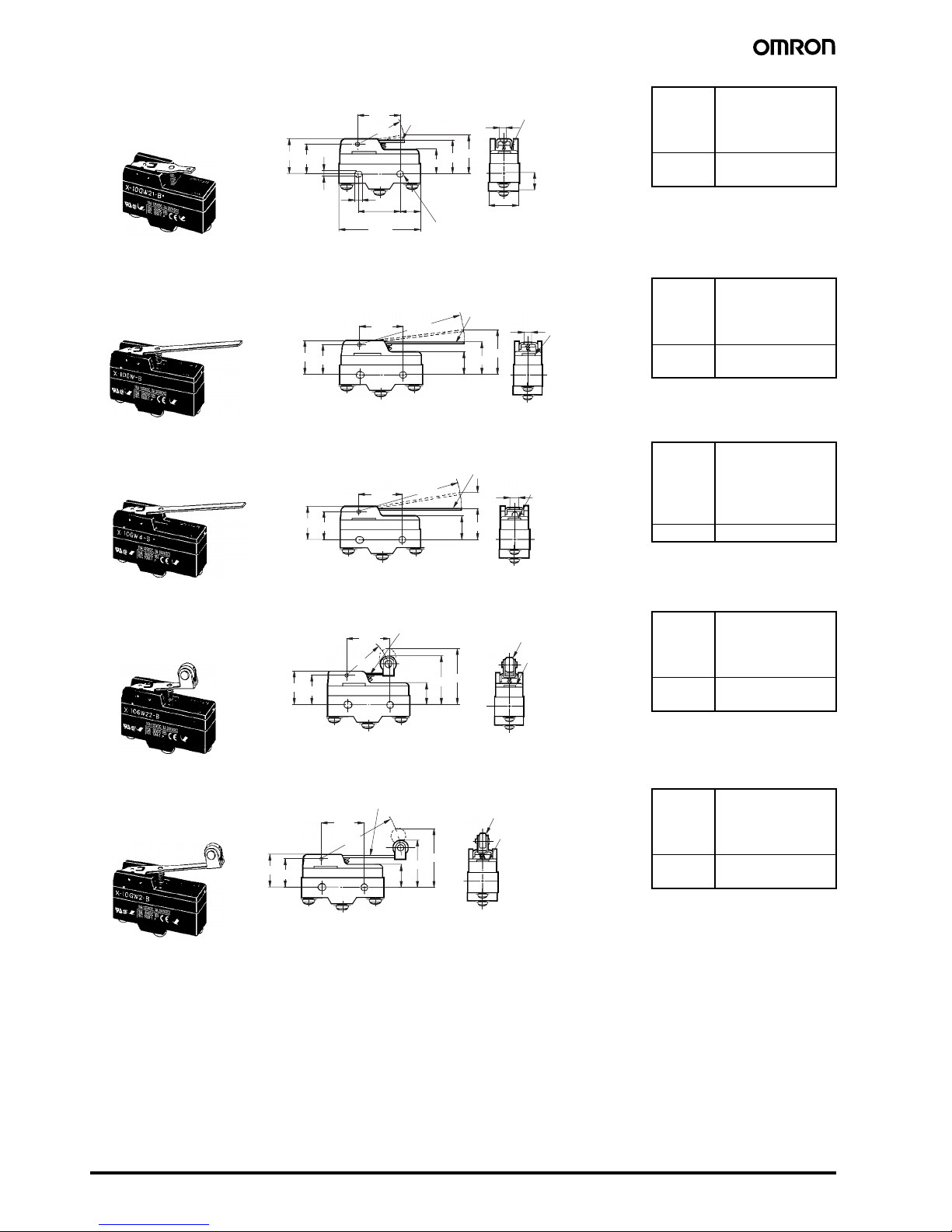
Dimensions
Note: 1. All units are in millimeters unless otherwise indicated.
2. Unless otherwise specified, a tolerance of ±0.4 mm applies to all dimensions.
■ Dimensions and Operating Characteristics
The models, illustrations, and graphics are for screw-terminal models. (The dimensions for models that are omitted here are the same as for pinplunger models.)
OF max.
RF min.
PT max.
OT min.
MD max.
5.00 N {510 gf}
1.12 N {114 gf}
0.9 mm
0.13 mm
0.18 mm
OP 15.9±0.4 mm
OF max.
RF min.
PT max.
OT min.
MD max.
5.00 N {510 gf}
1.12 N {114 gf}
0.9 mm
1.6 mm
0.18 mm
OP 28.2±0.5 mm
OF max.
RF min.
PT max.
OT min.
MD max.
5.00 N {510 gf}
1.12 N {114 gf}
0.9 mm
1.6 mm
0.18 mm
OP 21.2±0.5 mm
0 0.1 0.2 0.3 0.4 0.5 0.6 0.7 0.8 0.9
50,000
30,000
10,000
7,000
5,000
3,000
2,000
1,000
700
500
300
200
100
02468
10 12 14
5,000
3,000
2,000
1,000
700
500
300
200
100
70
50
30
20
10
Overtravel (mm) Switching current (A)
Durability (x10
3
operations)
Durability (x10
3
operations)
125 VDC L/R = 0
Ambient temperature: 20±2°C
Ambient humidity: 65±5%
Without load
Operating frequency: 240 operations/min
Ambient temperature: 20±2°C
Ambient humidity: 65±5%
Operating frequency: 20 operations/min
125 VDC
L/R = 7 ms
4.2
+0.075
−0.025
11.9
49.2
25.4±0.1
OP
PT
23.3±0.25
9.2
24.2
17.45±0.2
Pin Plunger
X-10G-B
4.36
+0.1
dia.
−0.05
2.3 dia.
2.3SR (see note 1)
(see note 2)
4.2
+0.075
dia.
−0.025
Note: 1. Stainless-steel pin plunger
2. Three vent holes
OP
PT
23.3±0.25
24.2
Slim Spring Plunger
X-10GS-B
5.2 dia.
9 dia.
4 dia.
(see note 2)
Note: 1. Stainless-steel pin plunger (flat, 1R chamfering)
2. Vent holes (3 places)
See
note 1
OP
PT
23.3±0.25
24.2
Short Spring Plunger
X-10GD-B
10 dia.
7.15 dia.
12.3 dia.
12SR (see note 1)
(see note 2)
Note: 1. Plated iron plunger
2. Three vent holes
Page 5

General-purpose Basic Switch X F-153
Limit
Switches
Note: 1. Stainless-steel pin plunger
2. Three vent holes
3. Imperfect screw part with a maximum length of 1.5 mm.
Note: 1. Stainless-steel roller
2. Three vent holes
3. Imperfect screw part with a maximum length of 1.5 mm.
Note: 1. Stainless-steel roller
2. Three vent holes
3. Imperfect screw part with a maximum length of 1.5 mm.
Note: 1. Reference value
2. Be sure to use the switch at the
rated OT value of 1.6 mm.
OF max.
RF min.
PT max.
OT min.
MD max.
5.00 N {510 gf}
1.12 N {114 gf}
0.9 mm
5.5 mm
0.18 mm
OP 21.8±0.8 mm
OF max.
RF min.
PT max.
OT min.
MD max.
5.00 N {510 gf}
1.12 N {114 gf}
0.9 mm
3.6 mm
0.18 mm
OP 33.4±1.2 mm
OF max.
RF min.
PT max.
OT min.
MD max.
5.00 N {510 gf}
1.12 N {114 gf}
0.9 mm
3.6 mm
0.18 mm
OP 33.4±1.2 mm
OF max.
RF min.
OT min.
MD max.
1.96 N {200 gf}
0.14 N {14 gf}
1.6 mm (see note)
2.3 mm
FP max.OP22.1 mm
17.4±0.8 mm
16.3
OP
PT
23.3±0.25
13.1
Panel Mount Plunger
X-10GQ-B
8.35 dia.
M12 × 1 mounting screw
16 dia.
See note 3
(see note 2)
11.9SR
(see
note 1)
Two hexagonal nuts
(2 t × 14 width across flats)
Two lock nuts
(2 t × 15.6 width across flats)
16.3
OP
PT
23.3±0.25
15.5
12.7 dia. × 4.8 (see note 1)
M12 × 1 mounting screw
16 dia.
See note 3
(see note 2)
Panel Mount Roller Plunger
X-10GQ22-B
Two hexagonal nuts
(3 t × 17 width across flats)
16.3
15.5
OP
PT
23.3±0.25
Panel Mount Cross Roller Plunger
X-10GQ21-B
16 dia.
See note 3
12.7 dia. × 4.8 (see note 1)
M12 × 1 mounting screw
(see note 2)
Two hexagonal nuts
(3 t × 17 width across flats)
4.8
FP
49.6±0.8
OP
Leaf Spring
X-10GL-B
t = 0.3 (see note 1)
(see note 2)
Note: 1. Stainless-steel spring lever
2. Three vent holes
Page 6
F-154 General-purpose Basic Switch X
OF max.
RF min.
OT min.
MD max.
2.45 N {250 gf}
0.31 N {32 gf}
2.1 mm
1.7 mm
FP max.OP25.5 mm
20.7±0.8 mm
OF max.
RF min.
OT min.
MD max.
1.08 N {110 gf}
0.14 N {14 gf}
4.8 mm
3.9 mm
FP max.OP34.6 mm
21.1±0.8 mm
OF max.
RF min.
PT max.
OT min.
MD max.
0.25 N {25 gf}
0.05 N {5 gf}
14.3 mm
4.8 mm
3.9 mm
OP 21.1±0.8 mm
OF max.
RF min.
OT min.
MD max.
2.16 N {220 gf}
0.34 N {35 gf}
2.4 mm
1.7 mm
FP max.OP37.1 mm
32.2±0.8 mm
OF max.
RF min.
OT min.
MD max.
1.42 N {145 gf}
0.21 N {21 gf}
4 mm
3 mm
FP max.OP40.5 mm
32.2±0.8 mm
t = 1 (see note 1)
4.2
+0.075
−0.025
20.2
25.4±0.1 11.9
49.2
26.2
28.2 R
14.4
OP
FP
4.9
9.2
17.45±0.2
17.4
Short Hinge Lever
X-10GW21-B
4.36
+0.1
dia.
−0.05
t = 1 (see note 1)
(see note 2)
4.2
+0.075
dia. holes
−0.025
Note: 1.
Stainless-steel lever
2.
Three vent holes
17.4
20.2
26.2
14.4
OP
FP
4.9
63.5R
t = 1 (see note 1)
(see note 2)
Note: 1.
Stainless-steel lever
2.
Three vent holes
Hinge Lever
X-10GW-B
20.2
26.2
14.4
OP
PT
4.9
63.5R
17.4
t= 1 (see note 1)
(see note 2)
Note: 1.
Stainless-steel lever
2.
Three vent holes
Low-force Hinge Lever
X-10GW4-B
17.4
20.2
26.2
26.6R
14.4
OP
FP
Short Hinge Roller Lever
X-10GW22-B
t = 1 (see note 3)
9.5 dia. × 4 (see note 1)
(see note 2)
Note: 1. Plastic roller
2. Three vent holes
3. Stainless-steel spring lever
20.2
26.2
48.5R
14.4
OP
FP
17.4
Hinge Roller Lever
X-10GW2-B
t = 1 (see note 3)
9.5 dia. × 4 (see note 1)
(see note 2)
Note: 1. Plastic roller
2. Three vent holes
3. Stainless-steel spring lever
Page 7

General-purpose Basic Switch X F-155
Limit
Switches
■ Terminals
Note: 1. Tighten the terminal screws to a torque of 0.78 to 1.18 N·m {8 to 12 kgf·cm}.
2. In case of DC voltage, set the COM to the positive terminal.
OF max.
RF min.
OT min.
MD max.
2.16 N {220 gf}
0.25 N {25 gf}
5.5 mm
2.1 mm
FP max.OP26.8 mm
21.1±0.8 mm
OF max.
RF min.
OT min.
MD max.
6.86 N {700 gf}
1.52 N {155 gf}
2 mm
0.75 mm
FP max.OP36.1 mm
32.2±0.8 mm
OF max.
RF min.
OT min.
MD max.
3.14 N {320 gf}
0.49 N {50 gf}
4 mm
1.5 mm
FP max.OP37.4 mm
32.2±0.8 mm
20.2
18.65
56R
14.4
OP
FP
4.9
17.4
Reverse Hinge Lever
X-10GM-B
t = 1 (see note 1)
(see note 2)
Note: 1.
Stainless-steel lever
2.
Three vent holes
17.4
20.2
18.65
14.4
OP
FP
18.5R
Reverse Short Hinge Lever
X-10GM22-B
t = 1 (see note 3)
9.5 dia. × 4 (see note 1)
(see note 2)
Note: 1.
Plastic roller
2.
Three vent holes
3.
Stainless-steel spring lever
20.2
18.65
40.6R
17.4
14.4
OP FP
Reverse Hinge Roller Lever
X-10GM2-B
t = 1 (see note 3)
9.5 dia. × 4 (see note 1)
(see note 2)
Note: 1.
Plastic roller
2.
Three vent holes
3. Stainless-steel spring lever
17.45±0.2
2020
9.2
49.2
17.45±0.2
25.4±0.1 11.9
6.4
49.2
Screw Terminals (-B)
Solder Terminal
Three, M4 × 5.5
Terminal screws
(with toothed
washer)
Appropriate terminal screw tightening torque:
0.78 to 1.18 N⋅m {8 to 12 kgf⋅cm}.
Page 8

F-156 General-purpose Basic Switch X
Precautions
Refer to the Technical Information for Basic Switches (Cat. No. C122) for common precautions.
■ Correct Use
Mounting
Use M4 mounting screws with plane washers or spring washers to
securely mount the Switch. Tighten the screws to a torque of 1.18 to
1.47 N·m {12 to 15 kgf·cm}
The Switch can be panel mounted, provided that the hexagonal nut
of the actuator is tightened to a torque of 2.94 to 4.9 N·m {30 to
50 kgf·cm}.
Mounting Holes
Handling
Set the common (COM) terminal to the positive terminal. If it is set to
the negative terminal, the Switch will not turn OFF.
When using the Switch under an inductive load, the arc suppression
capability varies depending on current. If the current becomes 0.6 to
1.2 A or of the time constant L/R exceeds 7 ms, be sure to provide an
arc suppressor.
Since the Switch incorporates a permanent magnet, attention must
be paid to the following points:
• Avoid mounting the Switch directly onto a magnetic substance.
• Do not subject the Switch to severe shocks.
• Avoid placing the Switch in a strong magnetic field.
• Be sure to prevent iron dust or iron chips from adhering to the
built-in magnet or the magnetic blowout function of the Switch
will be adversely affected.
• Do not apply thermal shock to the Switch, or the magnetic flux
will be diminished.
Since a ventilation hole is provided to avoid abnormal corrosion due
to operating conditions, provide a dustproofing device in locations
where the Switch is exposed to dust.
Do not change operating positions for the actuator. Changing the
position may cause malfunction.
Panel-mounted Model (X-10GQ@)
To side-mount the panel-mount Switch to the panel with screws,
remove the hexagonal nut from the actuator.
Too large a dog angle and too fast operating speed may damage the
Switch when the Switch is side-mounted on the panel.
Too fast operating speed and too long overtravel of the roller plunger
Switch may result in damage to the Switch.
■ Accessories (Order separately)
Refer to Z/A/X/DZ Common Accessories for details about Terminal
Covers, Separators, and Actuators.
25.4±0.1
Panel Mount Plunger Panel Mount Roller Plunger
12.5
+0.2
dia.
0
Two, 4.2-dia. mounting
holes or M4 screw holes
12.5
+0.2
dia.
0
In the interest of product improvement, specifications are subject to change without notice.
ALL DIMENSIONS SHOWN ARE IN MILLIMETERS.
To convert millimeters into inches, multiply by 0.03937. To convert grams into ounces, multiply by 0.03527.
Cat. No. B003-E1-08
 Loading...