

Page 1

Cat. No. W366-E1-10
SYSMAC
WS02-SIMC1-E
CX-Simulator Ver. 1.9
OPERATION MANUAL
Page 2

Page 3

SYSMAC WS02-SIMC1-E CX-Simulator Ver. 1.9
Operation Manual
Revised December 2009
Page 4

Notice:
OMRON products are manufactured for use according to proper procedures by a qualified operator and
only for the purposes described in this manual.
The following conventions are used to indicate and classify precautions in this manual. Always heed the
information provided with them. Failure to heed precautions can result in injury to people or damage to
property.
DANGER Indicates an imminently hazardous situation which, if not avoided, will result in death or
serious injury. Additionally, there may be severe property damage.
WARNING Indicates a potentially hazardous situation which, if not avoided, could result in death or
serious injury. Additionally, there may be severe property damage.
Caution Indicates a potentially hazardous situation which, if not avoided, may result in minor or
moderate injury, or property damage.
OMRON Product References
All OMRON products are capitalized in this manual. The word "Unit" is also capitalized when it refers to
an OMRON product, regardless of whether or not it appears in the proper name of the product.
The abbreviation "Ch," which appears in some displays and on some OMRON products, often means
"word" and is abbreviated "Wd" in documentation in this sense.
In this manual, "PLC" is used as the abbreviation for Programmable Controller.
Visual Aids
The following headings appear in the left column of the manual to help you locate different types of
information.
1, 2, 3... 1. Indicates lists of one sort or another, such as procedures, checklists, etc.
OMRON, 2008
All rights reserved. No part of this publication may be reproduced, stored in a retrieval system, or transmitted, in any form, or
by any means, mechanical, electronic, photocopying, recording, or otherwise, without the prior written permission of
OMRON.
No patent liability is assumed with respect to the use of the information contained herein. Moreover, because OMRON is
constantly striving to improve its high-quality products, the information contained in this manual is subject to change without
notice. Every precaution has been taken in the preparation of this manual. Nevertheless, OMRON assumes no responsibility
for errors or omissions. Neither is any liability assumed for damages resulting from the use of the information contained in
this publication.
Note Indicates information of particular interest for efficient and convenient opera-
tion of the product.
v
Page 5

About Upgrades:
Version 1.1
The following functions have been added to the CX-Simulator with the upgrade from Version 1.0 to
Version 1.1.
Actual Serial Communications Possible
In Ver.1.0, the contents of messages sent by serial communications instructions are displayed on the computer screen. In Ver.1.1, actual serial communications to an external serial communications device connected to a COM
port on the computer are also possible.
NT Link (1:N Mode) Possible
In Ver.1.1, communications with OMRON’s Programmable Terminal (PT)
connected to a COM port on the computer via NT Link are possible.
Multipoint Data Collection Tool Added
Time-series I/O memory data acquired from the actual PLC can be saved as a
Data Replay File (CSV format). Unlike Data Trace, data can not be acquired
every cycle. However, data of more than 50 words can be acquired.
WindowsMe/2000 Supported
Serial Number Entry on Installing Added
Version 1.2
The following functions have been added to the CX-Simulator with the upgrade from Version 1.1 to
Version 1.2.
New PLCs Supported
Simulation is newly supported for the following PLCs.
Series CPU Unit model numbers
CS CS1H-CPU67H/66H/65H/64H/63H
CS1G-CPU45H/44H/43H/42H
CJ CJ1H-CPU66H/65H
CJ1G-CPU45H/44H/43H/42H
CJ1G-CPU45/44
Functionality Improved
The following functions have been improved so that the same operation as
that performed by the actual PLC is performed by the CX-Simulator. (There
were some differences in operation with version 1.1.)
• Processing when using index registers for automatic incrementing or
decrementing with sequence output instructions.
• Processing the current EM bank is changed during execution of the ladder
program.
• Break processing for nested FOR-NEXT loops.
• Processing for decrementing counters in certain ladder program struc-
tures.
vi
Page 6

Simplified System Exit Processing
When the system is exited while the CX-Simulator is connected, a confirmation dialog box will appear and, upon confirmation, the CX-Simulator will be
disconnected and the system shut down.
Version 1.3
The following functions have been added to the CX-Simulator with the upgrade from Version 1.2 to
Version 1.3.
New PLCs Supported
Simulation is newly supported for the following PLCs.
Series CPU Unit model numbers
CJ CJ1M-CPU23/22/13/12
New Units in the CS and CJ Series are also supported for PLC Unit registration.
Starting and Connecting the CX-Simulator from the CX-Programmer
With CX-Programmer version 3.0 or higher, the CX-Simulator can be started
and connected (placed online) from the CX-Programmer. After going online,
program transfer to the CX-Simulator can be started immediately.
Windows XP Supported
Version 1.4
The following functions have been added to the CX-Simulator with the upgrade from Version 1.3 to
Version 1.4.
New PLCs Supported
Version 1.5
The changes that have been made from version 1.4 to version 1.5 of the CX-Simulator to enable support of new
CPU Unit models are explained here.
Simulation is newly supported for the following PLCs.
Series CPU Unit model numbers
CS CS1D-CPU67H/65H
CS1D-CPU67S/65S/44S/42S
CJ CJ1M-CPU23/22/21/13/12/11
New Units in the CS and CJ Series are also supported for PLC Unit registration.
New PLCs Supported
CX-Simulator version 1.5 supports the following new CPU Units.
Series CPU Unit model
CS CJ1H-CPU67H
CPU Unit Version Upgrade Compatibility
CX-Simulator version 1.5 supports the following CS/CJ-series CPU Units with
unit version 3.0.
Series Device type
CS/CJ CS1G-H, CS1H-H, CJ1G-H, CJ1H-H, CJ1M
vii
Page 7

Function Block (Ladder Programming Language) Simulation
CX-Simulator version 1.5 can be used to simulate function blocks that are supported for CS/CJ-series
CPU Units with unit version 3.0 (function block algorithms can be written in the ladder programming
language or in the structured text (ST)). Step execution of instructions contained in ladder programming
language or structured text within a function block, however, is not supported.
Precautions
CX-Simulator version 1.5 can simulate the operations of a CS/CJ-series CPU Unit with version 3.0 on a
personal computer. The simulation, however, operates differently from the actual CS/CJ-series CPU
Unit with unit version 3.0 in the system.
• Processing when using index registers for automatic incrementing or decrementing with sequence output instructions. No-protocol communications instructions sent to the serial port of
the Serial Communications Unit will not be executed.
CX-Simulator version 1.5 does not support no-protocol instructions (TXDU(256) and
RXDU(255)) sent to the serial port of the Serial Communications Unit and will not execute these
instructions.
• The Comms Instructions Settings in FB field in PLC Settings is disabled.
The Comms Instructions Settings in FB field (CPU Settings Tab) is a PLC setting specific to the
OMRON FB library. Therefore, this setting is disabled when using CX-Simulator version 1.5.
• Free Running Timers in Auxiliary Area words A000 and A001 are disabled.
The Auxiliary Area word 10-ms Incrementing Free Running Timer (A000) and 100-ms Incrementing Free Running Timer (A001) that are supported for CS/CJ-series CPU Units with version 3.0 or later cannot be used in simulation operations.
Version 1.6
The changes that have been made from version 1.5 to version 1.6 of the CX-Simulator to enable
support of new functions are explained here.
New PLCs Supported
CX-Simulator version 1.6 supports the following new CPU Units.
Series CPU Unit model
CP CP1H-XA/X
NSJ
(Controller
Section)
CX-Programmer Simulation Functions
If CX-Programmer version 6.1 or higher and CX-Simulator version 1.6 or
higher are installed, the following CX-Programmer simulation functions can be
used.
• Applicability: Ladder programs or programs in function blocks (ladder programs or ST)
• Simulation functions: Step execution, continuous step execution, scan
execution, and break-point operation (Note: I/O conditions cannot be set.)
Refer to the CX-Programmer Operation Manual (W446) for details.
G5D (Used for the NSJ5-TQ0@-G5D, NSJ5-SQ0@-G5D,
NSJ8-TV0@-G5D, NSJ10-TV0@-G5D, and NSJ12-TS0@-G5D)
Version 1.7
The changes that have been made from version 1.6 to version 1.7 of the CX-Simulator to enable
support of new functions are explained here.
viii
Page 8

New PLCs Supported
CX-Simulator version 1.7 supports the following new CPU Units.
Series CPU Unit model
CP
NSJ
(Controller
Section)
CP1H-XA@@@@-@
CP1H-X@@@@-@
CP1H-Y@@@@-@
M3D (Used for the NSJ5-TQ0@-M3D, NSJ5-SQ0@-M3D, and
NSJ8-TV0@-M3D)
Integrated Simulation with Screen Operations for Virtual PT
(Programmable Terminal)
The PLC-PT Integrated Simulation icon can be used to perform integrated
simulations using CX-Designer version 2.0 or higher and CX-Simulator version 1.7 or higher. This enables debugging by linking user program execution
on a virtual PLC with the CX-Programmer/CX-Simulator with screen operations for a virtual PT using the CX-Designer’s Test Tool.
• Starting the CX-Simulator:
The CX-Simulator is started by selecting the PLC-PT Integrated Simulation
menu item from CX-Designer version 2.0 or higher. (The user program is
automatically transferred to the CX-Simulator when it starts.)
• Connecting the CX-Simulator to virtual PT screens:
Automatically executed.
Refer to the operation manual for CX-Designer version 2.0 or higher for details.
Version 1.8
The changes that have been made from version 1.7 to version 1.8 of the CX-Simulator to enable
support of new functions are explained here.
New PLCs Supported
Version 1.9
The changes that have been made from version 1.8 to version 1.9 of the CX-Simulator to enable
support of new functions are explained here.
New PLCs Supported
Version 1.91
CX-Simulator version 1.8 supports the following new CPU Units.
Series CPU Unit model
CP
CJ CJ1H-CPU67H-R/66H-R/65H-R/64H-R
CX-Simulator version 1.9 supports the following new CPU Units.
Series CPU Unit model
CJ CJ2H-CPU68-EIP/67-EIP/66-EIP/65-EIP/64-EIP
CP1L-M@@@@-@
CP1L-L@@@@-@
The changes that have been made from version 1.9 to version 1.91 of the CX-Simulator to enable
support of new functions are explained here.
New PLCs Supported
CX-Simulator version 1.91 supports the following new CPU Units.
Series CPU Unit model
CJ CJ2H-CPU68/67/66/65/64
ix
Page 9

Version 1.94
The changes that have been made from version 1.9 to version 1.94 of the CX-Simulator to enable
support of new functions are explained here.
Support for Windows 7
Note This upgrade accompanies the upgrade of CX-One version 3.2 to CX-One
version 4.03.
x
Page 10
Unit Versions of CS/CJ/CP/NSJ-series CPU Units
Unit Versions
A “unit version” has been introduced to manage CPU Units in the
CS/CJ/CP/NSJ Series according to differences in functionality accompanying
Unit upgrades. This applies to the CJ2H, CS1-H, CJ1-H, CJ1M, CS1D, and
CP1H CPU Units.
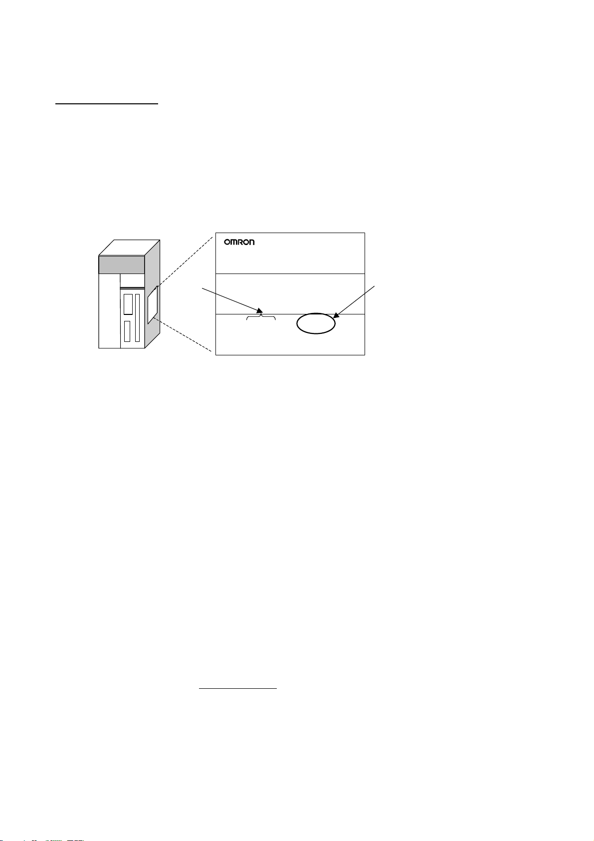
Notation of Unit Versions on Products
The unit version is given to the right of the lot number on the nameplate of the
products for which unit versions are being managed, as shown below.
Produce nameplate CS/CJ/CP-series CPU Unit
CS1H-CPU67H
CPU UNIT
Confirming Unit Versions
with Support Software
Lot No.
Lot No. 031001 0000 Ver.2.0
OMRON Corporation MADE IN JAPAN
Unit version
Example for unit version 2.0
• CS1-H, CJ1-H, and CJ1M CPU Units manufactured on or before November 4, 2003 do not have a unit version given on the CPU Unit (i.e., the location for the unit version shown above is blank).
• The unit version of the CJ1-H-R CPU Units begins at version 4.0.
• The unit version of the CS1-H, CJ1-H, and CJ1M CPU Units, as well as the
CS1D CPU Units for Single-CPU Systems, begins at version 2.0.
• The unit version of the CS1D CPU Units for Duplex-CPU Systems begins
at version 1.1.
• The unit version of the CP1H/CP1L CPU Units begins at version 1.0, except for the CP1H-Y@@@@-@, for which the unit version begins at version
1.1.
• CPU Units for which a unit version is not given are called Pre-Ver.
CPU Units, such as Pre-Ver. 2.0 CPU Units and Pre-Ver. 1.1 CPU Units.
CX-Programmer version 4.0 or later can be used to confirm the unit version
using one of the following two methods.
• Using the PLC Information
• Using the Unit Manufacturing Information (This method can be used for
Special I/O Units and CPU Bus Units as well.)
@.@
Note CX-Programmer version 3.3 or lower cannot be used to confirm unit ver-
sions.
PLC Information
• If you know the device type and CPU type, select them in the Change PLC
Dialog Box, go online, and select PLC - Edit - Information from the
menus.
• If you don’t know the device type and CPU type, but are connected directly
to the CPU Unit on a serial line, select PLC - Auto Online to go online,
and then select PLC - Edit - Information from the menus.
In either case, the following PLC Information Dialog Box will be displayed.
xi
Page 11
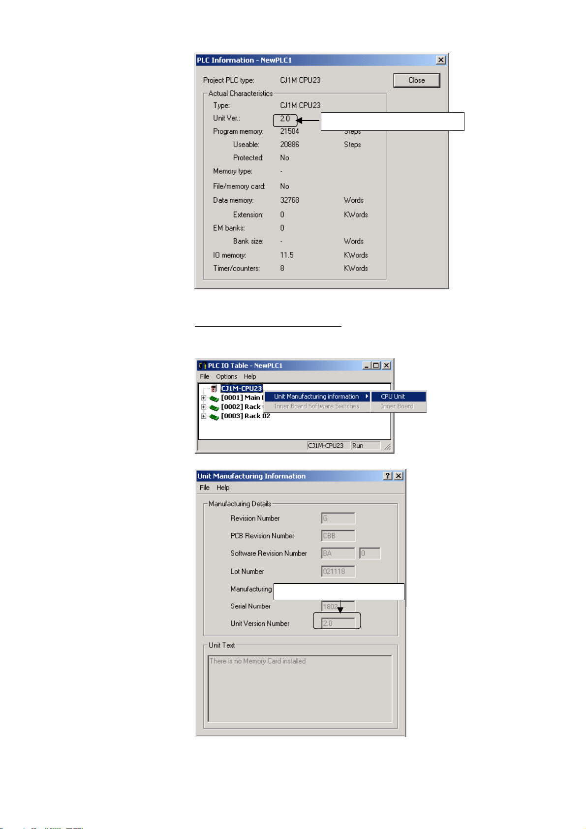
Unit version
Use the above display to confirm the unit version of the CPU Unit.
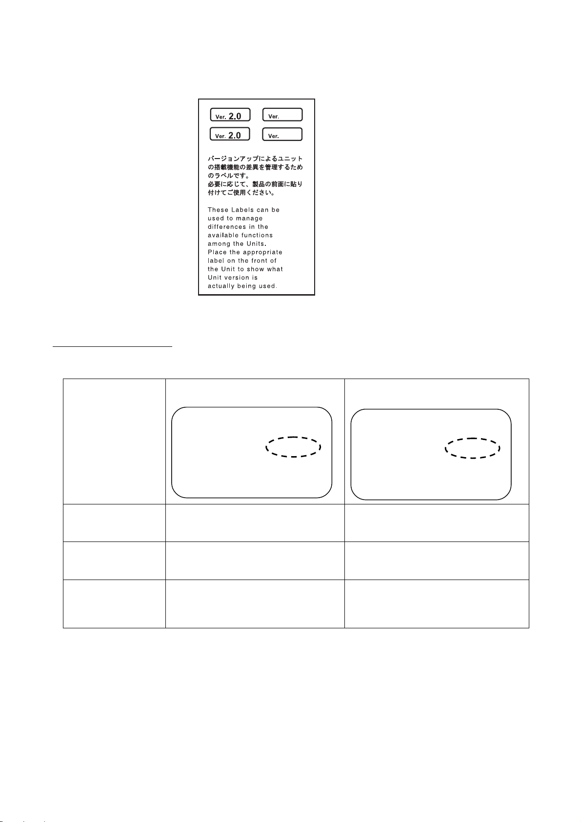
Unit Manufacturing Information
In the IO Table Window, right-click and select Unit Manufacturing information - CPU Unit.
The following Unit Manufacturing information Dialog Box will be displayed
Unit version
xii
Use the above display to confirm the unit version of the CPU Unit connected
online.
Page 12
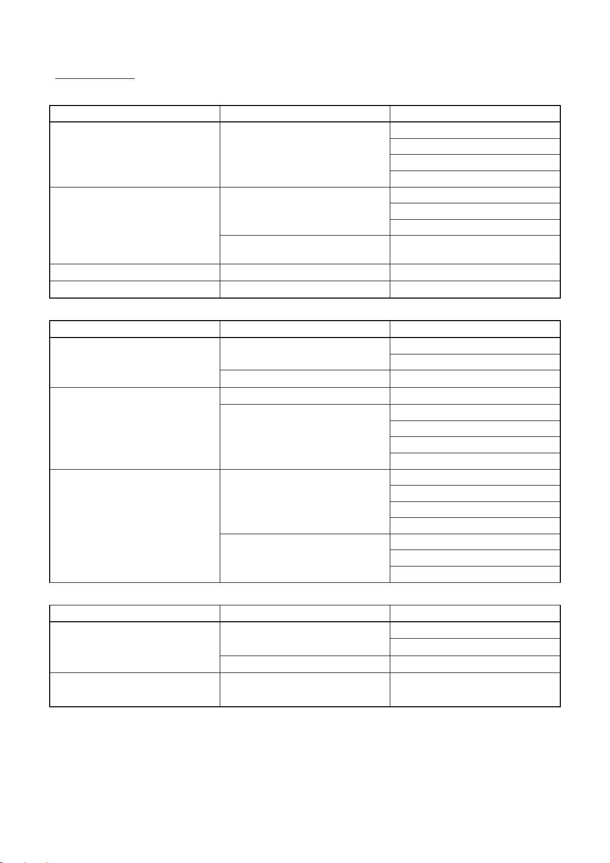
Using the Unit Version Labels
The following unit version labels are provided with the CPU Unit.
These labels can be attached to the front of previous CPU Units to differentiate
between CPU Units of different unit versions.
Unit Version Notation
Product nameplate
Meaning
Designating individual
CPU Units (e.g., the
CS1H-CPU67H)
Designating groups of
CPU Units (e.g., the
CS1-H CPU Units)
Designating an entire
series of CPU Units
(e.g., the CS-series
CPU Units)
In this manual, the unit version of a CPU Unit is given as shown in the following
table.
CPU Units on which no unit version is
given
Lot No. XXXXXX XXXX
OMRON Corporation MADE IN JAPAN
Units on which a version is given
(Ver.
@.@)
Lot No. XXXXXX XXXX
OMRON Corporation MADE IN JAPAN
Ver.@.
@
Pre-Ver. 2.0 CS1-H CPU Units
Pre-Ver. 2.0 CS1-H CPU Units
Pre-Ver. 2.0 CS-series CPU Units
CS1H-CPU67H CPU Unit Ver. @.@
CS1-H CPU Units Ver. @.@
CS-series CPU Units Ver. @.@
xiii
Page 13
Unit Versions
CS Series
Units Models Unit versions
CS1-H CPU Units
CS1D CPU Units
CS1 CPU Units
CS1 Version-1 CPU Units
CJ Series
Units Models Unit versions
CJ2 CPU Units
CJ1-H CPU Units
CJ1M CPU Units
CS1@-CPU@@H
Duplex-CPU Systems
CS1D-CPU@@H
Single-CPU Systems
CS1D-CPU@@S
CS1@-CPU@@
CS1@-CPU@@-V1
CJ2H-CPU6@-EIP
CJ2H-CPU6@
CJ1H-CPU@@H-R
CJ1@-CPU@@H
CJ1@-CPU@@P
CJ1M-CPU12/13
CJ1M-CPU22/23
CJ1M-CPU11/21
Unit version 4.0
Unit version 3.0
Unit version 2.0
Pre-Ver. 2.0
Unit version 1.2
Unit version 1.1
Pre-Ver. 1.1
Unit version 2.0
No unit version.
No unit version.
Unit version 1.1
Unit version 1.0
Unit version 1.1
Unit version 4.0
Unit version 4.0
Unit version 3.0
Unit version 2.0
Pre-Ver. 2.0
Unit version 4.0
Unit version 3.0
Unit version 2.0
Pre-Ver. 2.0
Unit version 4.0
Unit version 3.0
Unit version 2.0
CP Series
Units Models Unit versions
CP1H CPU Units
CP1L CPU Units
CP1H- X@@@@-@
CP1H- XA@@@-@
CP1H- Y@@@@-@
CP1L- M@@@@-@
CP1L- L@@@@-@
Note: CP-series Unit Versions and Supported Functions
Unit version 1.0 or 1.1 of the CP-series CP1H/CP1L CPU Units is equivalent to unit version 3.0 of the
CS/CJ-series CPU Units. Functions added for unit version 4.0 or later of the CS/CJ-series CPU Units
are not supported by the CP-series CP1H/CP1L CPU Units.
xiv
Unit version 1.1
Unit version 1.0
Unit version 1.1
Unit version 1.0
Page 14

NSJ Series
Models Unit versions
NSJ@-TQ@@(B)-G5D
NSJ@-TQ@@(B)-M3D
Unit version 3.0
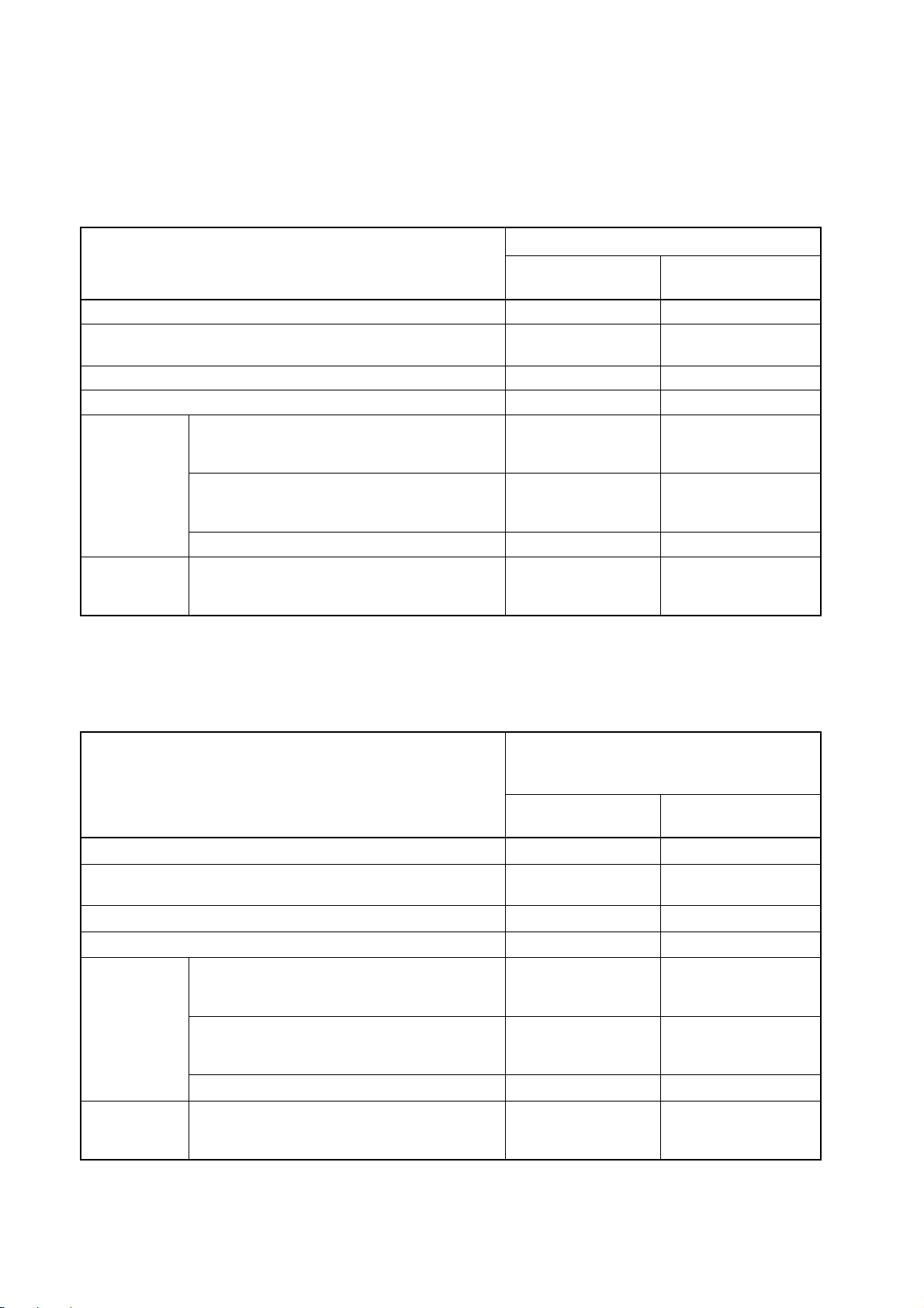
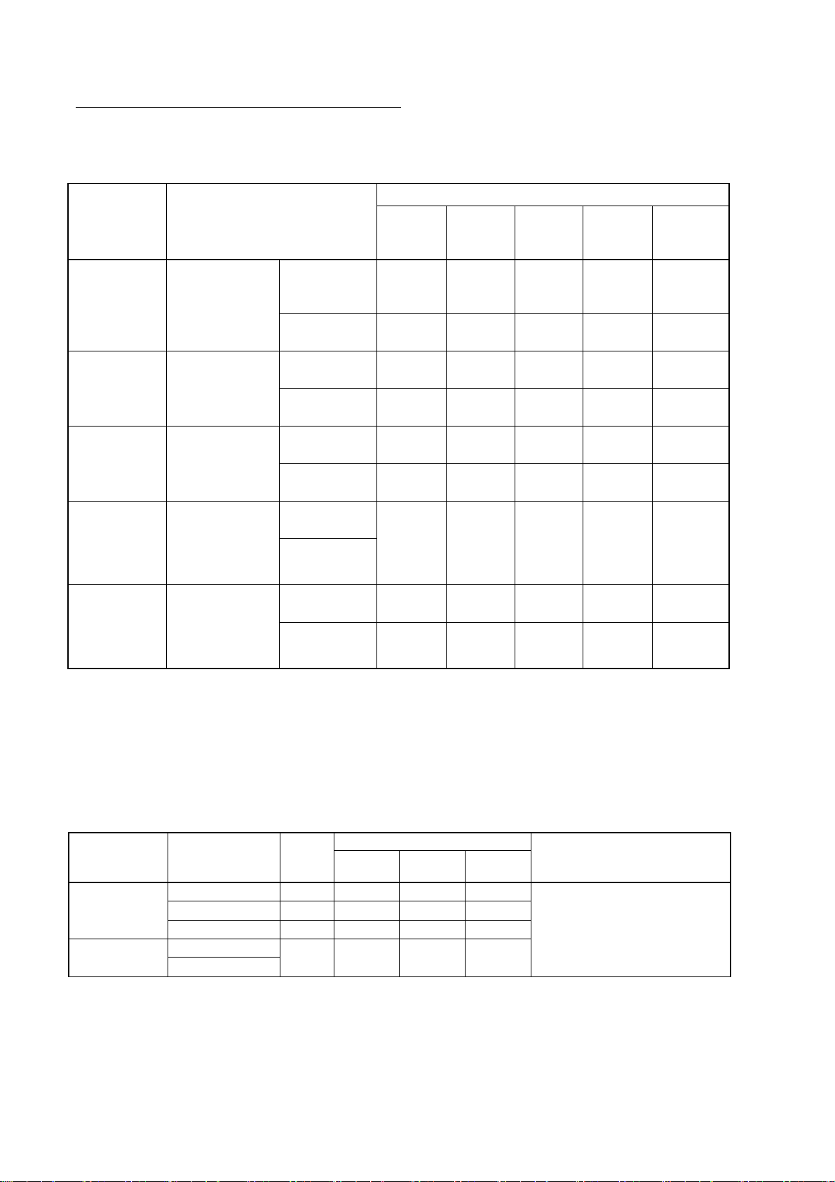
Function Support by Unit Version
The following tables show the functions supported by the CX-Programmer and
CX-Simulator depending on the unit version of the CPU Unit. Refer to 1-1-4
Summary of CX-Simulator Functions (Comparisons with Actual PLC) and 1-6
Comparison of CX-Simulator and SYSMAC CS/CJ-series PLCs for compari-
sons between CX-Simulator functions and the actual PLC.
The functions supported for CJ2 CPU Units with unit version 1.0 correspond to
those for CS/CJ Units with unit version 4.0 or later.
• Functions Supported for Unit Version 4.0 or Later
The following tables list the functions added for unit version 4.0 and supported
by the CX-Programmer. CX-Programmer version 7.0 or higher and
CX-Simulator version 1.7 or higher are required to use these functions.
Additional functions are supported if CX-Programmer version 7.2 or higher is
used.
CS1-H CPU Units
Function
Unit version 4.0 or
Online editing of function blocks
Note: This function cannot be used for simulations on the
CX-Simulator.
Input-output variables in function blocks OK ---
Text strings in function blocks OK ---
Number-Text String Conversion Instructions:
instructions
Using ST language programming in tasks OK with CX-
Using SFC programming in tasks OK with CX-
NUM4, NUM8, NUM16, STR4, STR8, and STR16
TEXT FILE WRITE (TWRIT) OK ---
OK ---
OK --- New application
Programmer Ver. 7.2 or
higher
Programmer Ver. 7.2 or
higher
CS1@-CPU@@H
later
---
---
CS1D CPU Units
Unit version 4.0 is not supported.
Other unit versions
xv
Page 15

CJ1-H/CJ1M CPU Units
Function
Online editing of function blocks
Note: This function cannot be used for simulations on the
CX-Simulator.
Input-output variables in function blocks OK ---
Text strings in function blocks OK ---
Number-Text String Conversion Instructions:
instructions
Using ST language programming in tasks OK with CX-
Using SFC programming in tasks OK with CX-
NUM4, NUM8, NUM16, STR4, STR8, and STR16
TEXT FILE WRITE (TWRIT) OK ---
CJ1@-CPU@@H, CJ1G-CPU@@P,
CJ1M-CPU@@
Unit version 4.0 or
later
OK ---
OK --- New application
--Programmer Ver. 7.2 or
higher
--Programmer Ver. 7.2 or
higher
Other unit versions
xvi
Page 16
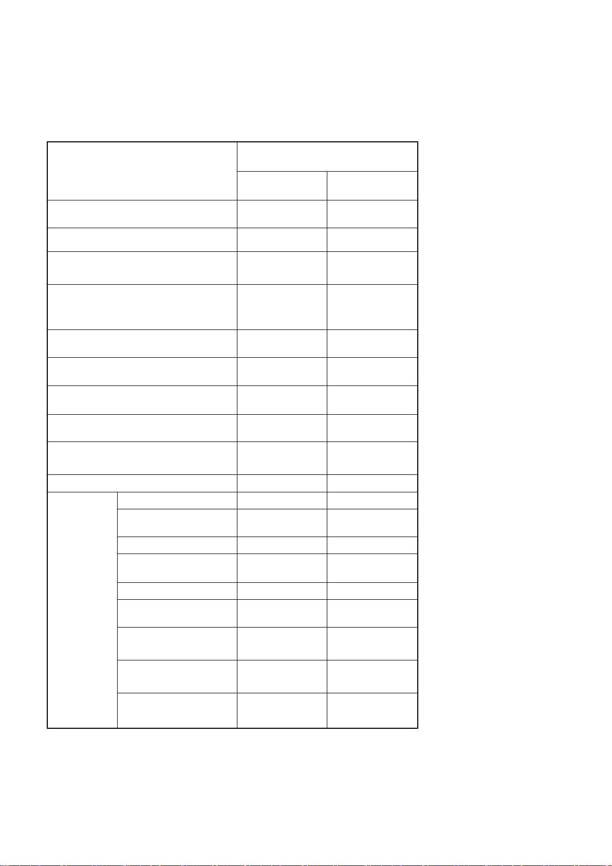
• Functions Supported for Unit Version 3.0 or Later
The following tables list the functions added for unit version 3.0 and supported
by the CX-Programmer. CX-Programmer version 5.0 or higher and
CX-Simulator version 1.5 or higher are required to use these functions.
CS1-H CPU Units
Function
Unit version 3.0 or
Function blocks OK ---
Serial Gateway (converting FINS commands to CompoWay/F
commands at the built-in serial port)
Comment memory (in internal flash memory) OK ---
Expanded simple backup data
New application
instructions
Additional instruction functions
TXDU(256), RXDU(255) (support no-protocol
communications with Serial Communications
Units with unit version 1.2 or later)
Model conversion instructions: XFERC(565),
DISTC(566), COLLC(567), MOVBC(568),
BCNTC(621)
Special function block instructions: GETID(286) OK ---
TXD(235) and RXD(236) instructions (support
no-protocol communications with Serial Communications Boards with unit version 1.2 or later)
OK ---
OK ---
OK ---
OK ---
CS1@-CPU@@H
later
CS1D CPU Units
Unit version 3.0 is not supported.
Other unit versions
CJ1-H/CJ1M CPU Units
Function
Function blocks
Serial Gateway (converting FINS commands to CompoWay/F
commands at the built-in serial port)
Comment memory (in internal flash memory)
Expanded simple backup data
New application instructions
Additional instruction functions
TXDU(256), RXDU(255) (support no-protocol
communications with Serial Communications
Units with unit version 1.2 or later)
Model conversion instructions: XFERC(565),
DISTC(566), COLLC(567), MOVBC(568),
BCNTC(621)
Special function block instructions: GETID(286)
PRV(881) and PRV2(883) instructions: Added
high-frequency calculation methods for calculating pulse frequency. (CJ1M CPU Units only)
CJ1@-CPU@@H
CJ1G-CPU@@P
CJ1M-CPU@@
Unit version 3.0 or
later
OK ---
OK ---
OK ---
OK ---
OK ---
OK ---
OK ---
OK ---
Other unit versions
xvii
Page 17
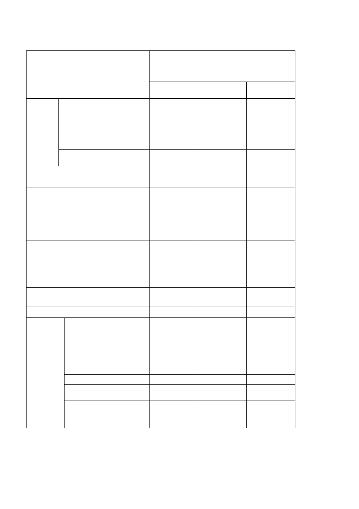
• Functions Supported for Unit Version 2.0 or Later
The following tables list the functions added for unit version 2.0 and supported
by the CX-Programmer. CX-Programmer version 4.0 or higher and
CX-Simulator version 1.4 or higher are required to use these functions.
CS1-H CPU Units
Function
Downloading and Uploading Individual
Tasks
Improved Read Protection Using Passwords
Write Protection from FINS Commands Sent
to CPU Units via Networks
Online Network Connections without I/O Tables
Communications through a Maximum of 8
Network Levels
Connecting Online to PLCs via NS-series
PTs
Setting First Slot Words
Automatic Transfers at Power ON without a
Parameter File
Automatic Detection of I/O Allocation
Method for Automatic Transfer at Power ON
CJ1-H CPU Units
(CJ1@-CPU@@H)
Unit version 2.0 or
later
OK ---
OK ---
OK ---
OK ---
OK ---
OK OK from lot number
OK for up to 64
groups
OK ---
--- ---
Other unit ver-
sions
030201
OK for up to 8
groups
Operation Start/End Times
New Application Instructions
MILH, MILR, MILC
=DT, <>DT, <DT, <=DT,
>DT, >=DT
BCMP2
GRY
TPO
DSW, TKY, HKY, MTR,
7SEG
EXPLT, EGATR, ESATR,
ECHRD, ECHWR
Reading/Writing CPU Bus
Units with IORD/IOWR
PRV2
OK ---
OK ---
OK ---
OK ---
OK OK from lot number
030201
OK ---
OK ---
OK ---
OK OK from lot number
030418
--- ---
xviii
Page 18
CS1D CPU Units
Function
Functions
unique to
CS1D CPU
Units
Downloading and Uploading Individual Tasks
Improved Read Protection Using Passwords
Write Protection from FINS Commands Sent to
CPU Units via Networks
Online Network Connections without I/O Tables
Communications through a Maximum of 8 Net-
work Levels
Connecting Online to PLCs via NS-series PTs
Setting First Slot Words
Automatic Transfers at Power ON without a Pa-
rameter File
Automatic Detection of I/O Allocation Method for
Automatic Transfer at Power ON
Operation Start/End Times
New application instructions
Duplex CPU Units --- OK OK
Online Unit Replacement OK OK OK
Duplex Power Supply Units OK OK OK
Duplex Controller Link Units OK OK OK
Duplex Ethernet Units --- OK OK
Unit removal without a Programming Device
MILH, MILR, MILC
=DT, <>DT, <DT, <=DT, >DT,
>=DT
BCMP2
GRY
TPO
DSW, TKY, HKY, MTR, 7SEG
EXPLT, EGATR, ESATR,
ECHRD, ECHWR
Reading/Writing CPU Bus Units
with IORD/IOWR
PRV2
CS1D CPU Units
for Single-CPU
Systems
(CS1D-CPU@@S)
Unit version 2.0 Unit version 1.1
--- OK (Unit version
OK --- ---
OK --- ---
OK --- ---
OK --- ---
OK --- ---
OK --- ---
OK for up to 64
groups
OK --- ---
--- --- ---
OK OK ---
OK --- ---
OK --- ---
OK --- ---
OK --- ---
OK --- ---
OK --- ---
OK --- ---
OK --- ---
OK --- ---
CS1D CPU Units for Duplex-CPU
Systems (CS1D-CPU@@H)
Pre-Ver. 1.1
or later
---
1.2 or later)
--- ---
xix
Page 19

CS1-H/CJ1M CPU Units
Function
Downloading and Uploading Individual
Tasks
Improved Read Protection Using Passwords
Write Protection from FINS Commands
Sent to CPU Units via Networks
Online Network Connections without I/O
Tables
Communications through a Maximum of
8 Network Levels
Connecting Online to PLCs via NS-series
PTs
Setting First Slot Words
Automatic Transfers at Power ON without a Parameter File
Automatic Detection of I/O Allocation
Method for Automatic Transfer at Power
ON
Operation Start/End Times
New application instructions
MILH, MILR, MILC
=DT, <>DT, <DT, <=DT,
>DT, >=DT
BCMP2
GRY
TPO
DSW, TKY, HKY, MTR,
7SEG
EXPLT, EGATR,
ESATR, ECHRD,
ECHWR
Reading/Writing CPU
Bus Units with
IORD/IOWR
PRV2
CJ1-H CPU Units CJ1M CPU Units
(CJ1@-CPU@@H)
(CJ1G-CPU@@P)
Unit version
2.0 or later
OK --- OK --- OK
OK --- OK --- OK
OK --- OK --- OK
OK --- (Supported if
OK --- OK --- OK
OK OK from lot
OK for up to 64
groups
OK --- OK --- OK
OK --- OK --- OK
OK --- OK --- OK
OK --- OK --- OK
OK --- OK --- OK
OK --- OK OK OK
OK OK from lot
OK --- OK --- OK
OK --- OK --- OK
OK --- OK --- OK
OK --- OK --- OK
--- --- OK, but only for
Other unit ver-
sions
I/O tables are
automatically
generated at
startup.)
number 030201
OK for up to 8
groups
number 030201
CJ1M-CPU12/13/22/23 CJ1M-CPU11/21
Unit version
2.0 or later
OK --- (Supported
OK OK from lot
OK for up to 64
groups
OK OK from lot
CPU Units with
built-in I/O
Other unit
versions
if I/O tables
are automatically generated at
startup.)
number
030201
OK for up to 8
groups
number
030201
--- OK, but only for
Unit version 2.0
or later
OK
OK
OK for up to 64
groups
OK
CPU Units with
built-in I/O
xx
Page 20
Functions Supported by Unit Version for CP-series CPU Units
Functions Supported by Unit Version 1.0 and 1.1
Functionality is the same as that for CS/CJ-series CPU Units with unit version 3.0.
The functionality added for CS/CJ-series CPU Unit unit version 4.0 is not
supported.
CP1H CPU Units
• CX-Programmer version 6.11 or higher is required to use
CP1H-X@@@@-@/XA@@@@-@ with unit version 1.1 or 1.0.
• CX-Programmer version 6.20 or higher is required to use
CP1H-Y@@@@-@ with unit version 1.1.
CPU Unit CP1H CPU Unit
Model CP1H-X@@@@-@
CP1H-XA@@@@-@
(See note 1.)
Unit version
Ver. 1.1 or
Ver. 1.0 Ver. 1.1
CP1H-Y@@@@-
@
(See note 2.)
later
Function
Pulse
outputs
Allocated
built-in I/O terminals
4 axes at
100 kHz
2 axes at
100 kHz
2 axes at
2 axes at 100
kHz
30 kHz
Special pulse
None 2 axes at 1 kHz
output terminals
Note 1: The unit version for the CP1H-X@@@@-@/XA@@@@-@ begins at 1.0.
2: The unit version for the CP1H-Y@@@@-@ begins at 1.1.
3: CX-Programmer version 7.11 or higher is required to use CP1L CPU Units
with unit version 1.0.
xxi
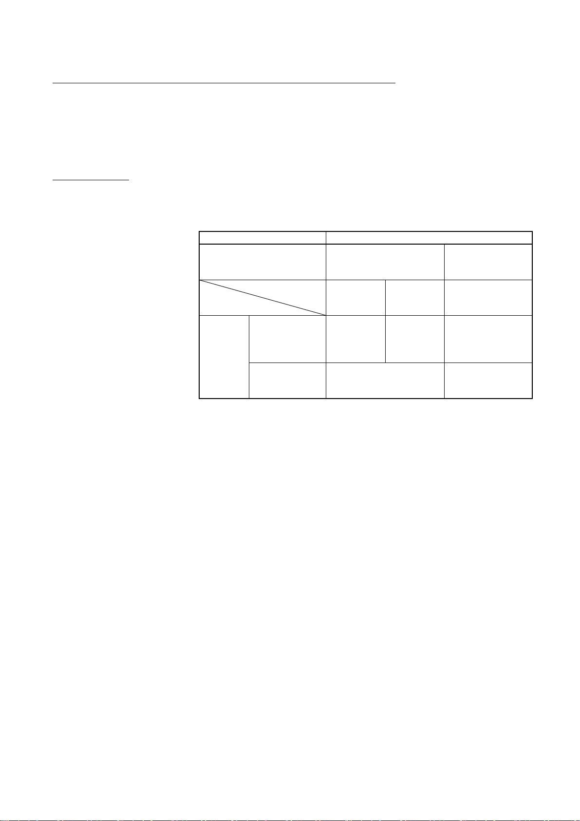
Page 21
Unit Versions and Programming Devices
The following tables show the relationship between unit versions and
CX-Programmer versions.
Unit Versions of CS/CJ-series CPU Units and Programming Devices
CX-Programmer CPU Unit Functions
CS/CJ Series,
unit version
4.0
unit version
3.0
unit version
2.0
CS1D CPU
Units for Single-CPU Systems, unit version 2.0
Units for Duplex-CPU
Systems, unit
version 1.
Functions added
for unit version
4.0
Functions added
for unit version
3.0
Functions added
for unit version
2.0
Functions added
for unit version
2.0
Functions added
for unit version
1.1
Using new
functions
Not using new
functions
Using new
functions
Not using new
functions
Using new
functions
Not using new
functions
Using new
functions
Not using new
functions
Using new
functions
Not using new
functions
Ver. 3.3 Ver. 4.0 Ver. 5.0
Ver. 6.0
--- --- --- OK
OK OK OK OK OK
--- --- OK OK OK CS/CJ Series,
OK OK OK OK OK
--- OK OK OK OK CS/CJ Series,
OK OK OK OK OK
--- OK OK OK OK
--- OK OK OK OK CS1D CPU
OK OK OK OK OK
Ver. 7.0 Ver. 7.2
or
higher
OK
(See
note 1.)
(See note
1.)
Note 1: As shown above, there is no need to upgrade the CX-Programmer ver-
sion as long as the functions added newer unit versions are not used.
2: CX-Programmer version 7.0 or higher is required to use functions added
for unit version 4.0. Additional functions are supported if CX-Programmer
version 7.2 or higher is used.
Unit Versions of CP-series CPU Units and Programming Devices
CX-Programmer version CPU Unit Model Unit
Ver. 6.11 Ver. 6.20 Ver. 7.11
or higher
CP1H CPU Units
CP1H-X@@@@-@
CP1H-XA@@@@-@
CP1H-Y@@@@-@
CP1L-M@@@@-@ CP1L CPU Units
CP1L-L@@@@-@
version
Ver. 1.1 OK OK OK
Ver. 1.0 OK OK OK
Ver. 1.1 --- OK OK
Ver. 1.0 --- --- OK
Note 1: As shown above, there is no need to upgrade the CX-Programmer ver-
sion as long as the functions added newer unit versions are not used.
2: CX-Programmer version 7.0 or higher is required to use functions added
for unit version 4.0. Additional functions are supported if CX-Programmer
version 7.2 or higher is used.
Programming Console
Cannot be used.
xxii
Page 22
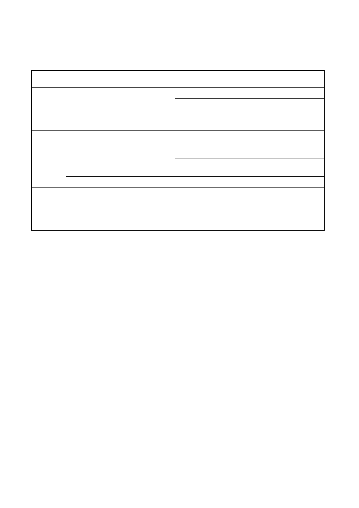
Device Type Setting
The unit version does not affect the setting made for the device type on the
CX-Programmer. Select the device type as shown in the following table regardless of the unit version of the CPU Unit.
Series CPU Unit group CPU Unit model Device type setting on
CX-Programmer
CS Series
CJ Series
CP Series
CS1G-H CS1-H CPU Units
CS1H-H
CS1D-H (or CS1H-H)
CS1D-S
CJ2H
CJ1G-H CJ1-H CPU Units
CJ1H-H
CJ1M
CP1H
CP1L
CS1D CPU Units for Duplex-CPU Systems
CS1D CPU Units for Single-CPU Systems
CJ2 CPU Units
CJ1M CPU Units
CP1H CPU Units
CP1L CPU Units
CS1G-CPU@@H
CS1H-CPU@@H
CS1D-CPU@@H
CS1D-CPU@@S
CJ2H-CPU6@(-EIP)
CJ1G-CPU@@H
CJ1G-CPU@@P
CJ1H-CPU@@H-R
CJ1H-CPU@@H
CJ1M-CPU@@
CP1H-X@@@@-@C
P1H-XA@@@@-@
CP1H-Y@@@@-@
CP1L-M@@@@-@
CP1L-L@@@@-@
Note Device types not supported by the CX-Programmer version that is being used will not be
displayed on the pull-down list of the Device type Field.
xxiii
Page 23
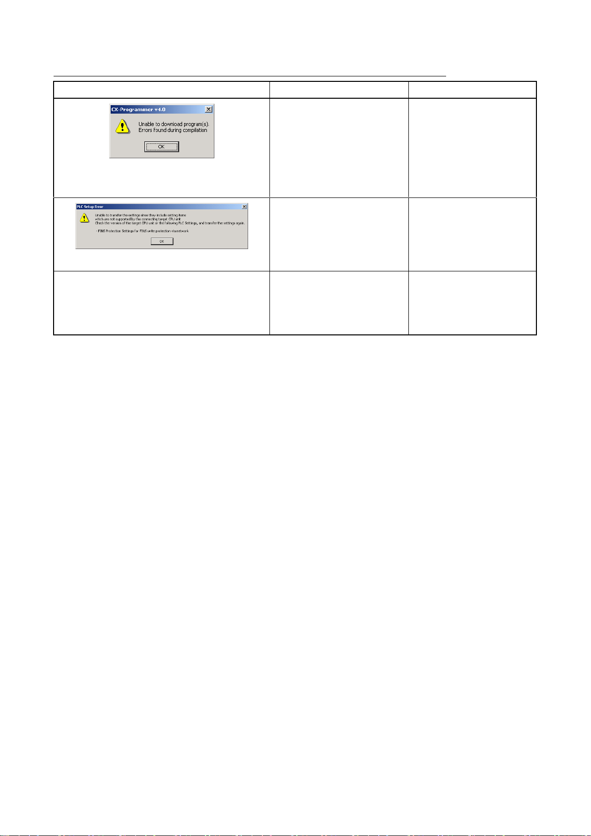
Troubleshooting Problems with Unit Versions on the CX-Programmer
Problem Cause Solution
After the above message is displayed, a compiling
error will be displayed on the Compile Tab Page in
the Output Window.
"????" is displayed in a program transferred from the
PLC to the CX-Programmer.
An attempt was made to
download a program containing
instructions supported only by
later unit versions or a CPU Unit
to a previous unit version.
An attempt was to download a
PLC Setup containing settings
supported only by later unit versions or a CPU Unit to a previous
unit version.
An attempt was made to upload a
program containing instructions
supported only by higher versions of CX-Programmer to a
lower version.
Check the program or change
to a CPU Unit with a later unit
version.
Check the settings in the PLC
Setup or change to a CPU
Unit with a later unit version.
New instructions cannot be
uploaded to lower versions of
CX-Programmer. Use a higher
version of CX-Programmer.
xxiv
Page 24

xxv
Page 25

TABLE OF CONTENTS
PRECAUTIONS..............................................................................................XXXVII
1 Intended Audience......................................................................................................................................... xxxviii
2 General Precautions ....................................................................................................................................... xxxviii
3 Safety Precautions .........................................................................................................................................xxxviii
4 Application Precautions................................................................................................................................... xxxix
SECTION 1
INTRODUCTION........................................................................................................1
1-1 What Is the CX-Simulator? ...................................................................................................................................... 2
1-2 Features .................................................................................................................................................................... 9
1-3 Convenient Functions............................................................................................................................................. 13
1-4 Applicable PLC models and Computers ................................................................................................................ 14
1-5 Operation List Arranged by Purpose...................................................................................................................... 16
1-6 Comparison of CX-Simulator and SYSMAC CS/CJ-series PLCs ......................................................................... 18
SECTION 2
SETUP ........................................................................................................................ 25
2-1 Installing and Uninstalling the Software ................................................................................................................ 26
SECTION 3
BASIC OPERATION ............................................................................................... 37
3-1 Starting Methods for the CX-Simulator ................................................................................................................. 38
3-2 Starting and Going Online from the CX-Programmer ........................................................................................... 39
3-3 Starting and Exiting from CX-Simulator Menus.................................................................................................... 42
3-4 Outline of Operation Procedure ............................................................................................................................. 44
3-5 Creating a New PLC............................................................................................................................................... 48
3-6 Each Part of the Windows ...................................................................................................................................... 58
3-7 System Status Setting Window .............................................................................................................................. 60
3-8 Connecting to the CX-Programmer Version 2.1 or Lower .................................................................................... 71
3-9 Debug Console Window ........................................................................................................................................ 76
SECTION 4
DEBUGGING PROGRAMS.................................................................................. 101
4-1 Debugging Using the CX-Programmer................................................................................................................ 102
4-2 Debugging Operation ........................................................................................................................................... 103
4-3 Step Run and Break.............................................................................................................................................. 107
4-4 Task Debugging ................................................................................................................................................... 115
SECTION 5
DEBUGGING SERIAL COMMUNICATIONS.................................................. 119
5-1 Outline of Serial Communications ....................................................................................................................... 120
5-2 Serial Communications Settings........................................................................................................................... 123
5-3 Serial Communications Connection ..................................................................................................................... 127
5-4 Connecting PT via NT Link ................................................................................................................................. 130
xxvi
Page 26

5-5 Examples of Serial Communications Debugging................................................................................................. 131
SECTION 6
DEBUGGING NETWORK COMMUNICATIONS ........................................... 135
6-1 Outline of Network Communications................................................................................................................... 136
6-2 Network Communications Settings...................................................................................................................... 139
6-3 Network Connection............................................................................................................................................. 142
6-4 Example of Debugging Network Communications.............................................................................................. 143
6-5 Available FINS Commands.................................................................................................................................. 147
SECTION 7
CONNECTION WITH APPLICATION PROGRAMS ..................................... 149
7-1 Outline of Connection .......................................................................................................................................... 150
7-2 Connection with Application Programs ............................................................................................................... 151
SECTION 8
DEBUGGING USING VIRTUAL EXTERNAL INPUTS.................................. 157
8-1 Outline of Virtual External Input Function .......................................................................................................... 158
8-2 Debugging Using Virtual External Inputs............................................................................................................ 159
8-3 Generating Virtual External Inputs ...................................................................................................................... 162
8-4 Running by Virtual External Inputs ..................................................................................................................... 176
8-5 Checking the Result.............................................................................................................................................. 184
SECTION 9
CPU UNIT OPERATION ...................................................................................... 187
9-1 CPU Unit Operation ............................................................................................................................................. 188
9-2 Cycle Time and Time ........................................................................................................................................... 192
9-3 I/O Memory Allocation ........................................................................................................................................ 200
9-4 Other Functions .................................................................................................................................................... 237
SECTION 10
TROUBLESHOOTING.......................................................................................... 239
10-1 Error Processing ................................................................................................................................................. 240
10-2 Alarms and Remedies......................................................................................................................................... 245
10-3 Other Tips for Troubleshooting.......................................................................................................................... 247
APPENDIX
HOW TO USE DATA TRACE RECORDING TOOL ....................................... 251
REVISION HISTORY............................................................................................ 263
xxvii
Page 27

About this Manual:
This manual describes operating procedures of the CX-Simulator for SYSMAC CS/CJ/CP/NSJ-series
Programmable Controllers (PLCs).
Please read this manual and all related manuals listed in the following table and be sure you understand
the information provided before attempting to operate the CX-Simulator.
Name Cat. No. Use Contents
SYSMAC WS02-SIMC1-E
CX-Simulator Operation Manual (this
manual)
CX-One Setup Manual W463 To install software from
CX-Programmer Ver. 9
Operation Manual
CX-Programmer Ver. 9
Operation Manual
Function Blocks/Structured Texts
CXONE-AL@@C-V4/ AL@@D-V4
CX-Integrator Operation Manual
CJ Series CJ2 CPU Unit Hardware
User’s Manual
CJ2H-CPU6@-EIP, CJ2H-CPU6@
CJ Series CJ2 CPU Unit Software
User’s Manual
CJ2H-CPU6@-EIP, CJ2H-CPU6@
SYSMAC CS Series
CS1G/H-CPU@@-EV1,
CS1G/H-CPU@@H
Programmable Controllers
Operation Manual
SYSMAC CJ Series
CJ1H-CPU@@H-R, CJ1G-CPU@@,
CJ1G/H-CPU@@H,
CJ1M-CPU@@
Programmable Controllers
Operation Manual
SYSMAC CS/CJ/NSJ Series
CS1G/H-CPU@@-EV1,
CS1G/H-CPU@@H,
CS1D-CPU@@H, CS1D-CPU@@S,
CJ1H-CPU@@H-R, CJ1G-CPU@@,
CJ1G/H-CPU@@H, CJ1M-CPU@@,
NSJ@-@@@@(B)-G5D,
NSJ@-@@@@(B)-M3D
Programmable Controllers
Programming Manual
SYSMAC CS/CJ/NSJ Series
CS1G/H-CPU@@-EV1,
CS1G/H-CPU@@H,
CS1D-CPU@@H, CS1D-CPU@@S,
CJ2H-CPU6@-EIP, CJ2H-CPU6@,
CJ1H-CPU@@H-R, CJ1G-CPU@@,
CJ1G/H-CPU@@H, CJ1M-CPU@@,
NSJ@-@@@@(B)-G5D,
NSJ@-@@@@(B)-M3D
Programmable Controllers
Instructions Reference Manual
W366 To learn how to operate
W446
W447
W464 To make network settings
W472 --- Provides the following information on the CJ2 CPU Units:
W473 --- Provides the following information on the CJ2 CPU Units:
W339 To learn the basic specifi-
W393 To learn the basic specifi-
W394 To learn the functions of
W474 To learn details of the
CX-Simulator for Windows
personal computers. To
use simulation functions
on the CX-Programmer,
with CX-Programmer Ver.
6.1 or higher.
CX-One.
To learn how to operate
CX- Programmer for Windows personal computers.
and monitor.
cations of the CS-series
PLCs, including a basic
outline, settings, installation, and maintenance.
cations of the CJ-series
PLCs, including a basic
outline, settings, installation, and maintenance.
the CS/CJ-series PLCs.
instruction language.
Describes the operation of the CX-Simulator.
Use this together with the CX-Programmer Operation Manual
(W446), CS Series and CJ Series Operation Manuals (CS
Series: W339, CJ Series: W393), and CS/CJ Series Instructions Reference Manual (W340).
Provides an outline of the CX-One FA integration software
package, and describes the method for installing CX-One.
Describes the operation of the CX- Programmer.
For programming, use this together with the CJ2H Program-
mable Controllers Hardware User’s Manual (W472), the CJ2H
Programmable Controllers Software User’s Manual (W473),
and the Programmable Controllers Instructions Reference
Manual (W474).
Describes the operation of the CX- Integrator.
Overview, system design, hardware specifications, hardware
settings, installation, wiring, maintenance, and troubleshooting.
Use this manual together with the CJ2 CPU Unit Software
User’s Manual (W473).
Overview of CPU Unit operation, programming, software
settings, CPU Unit functions, and system startup.
Use this manual together with the CJ2 CPU Unit Hardware
User’s Manual (W472).
Describes the features, system configuration design, installation, wiring, I/O memory allocation, and troubleshooting of the
CS-series PLCs.
Use this together with the Programming Manual (W394).
Describes the features, system configuration design, installation, wiring, I/O memory allocation, and troubleshooting of the
CJ-series PLCs.
Use this together with the Programming Manual (W394).
Describes the programming, task functions, file memory functions, and other functions of the CS/CJ-series PLCs.
Describes the details of the instruction language.
For programming, use this together with the CS Series and CJ
Series Operation Manuals (CS Series: W339, CJ Series:
W393), and Programming Manual (W394).
xxviii
Page 28

Name Cat. No. Use Contents
SYSMAC CS/CJ/CP/NSJ Series
CS1G/H-CPU@@-EV1,
CS1G/H-CPU@@H,
CS1D-CPU@@H, CS1D-CPU@@S,
CJ2H-CPU6@-EIP, CJ2H-CPU6@,
CJ1H-CPU@@H-R, CJ1G-CPU@@,
CJ1M-CPU@@, CJ1G-CPU@@P,
CJ1G/H-CPU@@H,
CS1W-SCU@@-V1,
CS1W-SCB@@-V1,
CJ1W-SCU@@-V1,
CP1H-X@@@@-@,
CP1H-XA@@@@-@,
CP1H-Y@@@@-@,
NSJ@-@@@@ (B)-G5D,
NSJ@-@@@@(B)-M3D
Communications Commands Reference Manual
NSJ5-TQ@@(B)-G5D
NSJ5-SQ@@(B)-G5D
NSJ8-TV@@(B)-G5D
NSJ10-TV@@(B)-G5D
NS12-TS@@(B)-G5D
NSJ Series NSJ Controllers
Operation Manual
CP1H-X@@@@-@,
CP1H-XA@@@@-@,
CP1H-Y@@@@-@,
SYSMAC CP Series
CP1H CPU Unit
Operation Manual
CP1L-M@@@@-@,
CP1L-L@@@@-@,
CP Series CP1L Operation Manual
CP1H-X@@@@-@,
CP1H-XA@@@@-@,
CP1H-Y@@@@-@,
CP1L-M@@@@-@,
CP1L-L@@@@-@
SYSMAC CP Series
CP1H/CP1L CPU Unit Programming
Manual
W342 To learn about communi-
cations commands addressed to
CS/CJ/CP-series CPU
Units and NSJ-series
Controllers.
W452 To learn the basic specifi-
cations of the NSJ-series
NSJ Controllers, including
a basic outline, settings,
installation, and maintenance.
W450 To learn the basic specifi-
cations of the CP-series
CP1H CPU Units, including a basic outline, settings, installation, and
maintenance.
W462 To learn the basic specifi-
cations of the CP-series
CP1L CPU Units, including
a basic outline, settings,
installation, and maintenance.
W451 To learn about program-
ming CP-series
CP1H/CP1L CPU Units.
Describes the following information.
• C-mode commands
• FINS commands
Note: Refer to this manual when sending C-mode or FINS
commands to the CPU Unit.
This manual describes commands addressed to the
CPU Unit without reference to the communications path.
(Commands can be sent via the serial ports on the CPU
Unit, ports on a Serial Communications Board or Unit, or
ports on Communications Units.)
Describes the following information about the NSJ-series NSJ
Controllers:
Overview and features
Designing the system configuration
Installation and wiring
I/O memory allocations
Troubleshooting and maintenance
Use this manual in combination with the following manuals:
SYSMAC CS Series Operation Manual (W339), SYSMAC CJ
Series Operation Manual (W393), SYSMAC CS/CJ Series
Programming Manual (W394), and NS-V1/-V2 Series Setup
Manual (V083)
Provides the following information on the CP Series CP1H
CPU Unit:
• Overview/Features
• System configuration
• Mounting and wiring
• I/O memory allocation
• Troubleshooting
Use this manual together with the CP1H Programmable Con-
trollers Programming Manual (W451).
Provides the following information on the CP Series CP1L
CPU Unit:
• Overview/Features
• System configuration
• Mounting and wiring
• I/O memory allocation
• Troubleshooting
Use this manual together with the CP1H Programmable Con-
trollers Programming Manual (W451).
Provides the following information on the CP Series
CP1H/CP1L CPU Unit:
• Programming instructions
• Programming methods
• Tasks
WARNING
Failure to read and understand the information provided in this manual may result in
personal injury or death, damage to the product, or product failure. Please read each
section in its entirety and be sure you understand the information provided in the section
and related sections before attempting any of the procedures or operations given.
xxix
Page 29

About this Manual, Continued
This manual contains the following sections.
Section 1 introduces the special features and functions of the CX-Simulator and a comparison between
SYSMAC CS/CJ/CP/NSJ-series PLCs
Section 2 provides the information on how to setup the CX-Simulator.
Section 3 describes the basic operation of the CX-Simulator.
Section 4 describes how to debug user programs.
Section 5 describes how to debug Serial Communications functions.
Section 6 describes how to debug Network Communications functions.
Section 7 describes how to connect with application programs.
Section 8 provides information on how to debug using virtual external inputs.
Section 9 describes operations of the CPU Unit including cycle times and I/O Memory allocation.
Section 10 provides information on errors and alarms that occur during the operation along with the
remedies.
Appendix provides information on how to use the Data Trace Recording Tool.
xxx
Page 30

xxxi
Page 31

Read and Understand This Manual
Please read and understand this manual before using the product. Please consult your OMRON representative if you have any questions or comments.
Warranty and Limitations of Liability
WARRANTY
(1) The warranty period for the Software is one year from either the date of purchase or the date on which the
Software is delivered to the specified location.
(2) If the User discovers a defect in the Software (i.e., substantial non-conformity with the manual), and returns it
to OMRON within the above warranty period, OMRON will replace the Software without charge by offering
media or downloading services from the Internet. And if the User discovers a defect in the media which is attributable to OMRON and returns the Software to OMRON within the above warranty period, OMRON will replace the defective media without charge. If OMRON is unable to replace the defective media or correct the
Software, the liability of OMRON and the User’s remedy shall be limited to a refund of the license fee paid to
OMRON for the Software.
LIMITATIONS OF LIABILITY
(1) THE ABOVE WARRANTY SHALL CONSTITUTE THE USER’S SOLE AND EXCLUSIVE REMEDIES
AGAINST OMRON AND THERE ARE NO OTHER WARRANTIES, EXPRESSED OR IMPLIED, INCLUDING
BUT NOT LIMITED TO, WARRANTY OF MERCHANTABILITY OR FITNESS FOR A PARTICULAR
PURPOSE. IN NO EVENT WILL OMRON BE LIABLE FOR ANY LOST PROFITS OR OTHER INDIRECT,
INCIDENTAL, SPECIAL, OR CONSEQUENTIAL DAMAGES ARISING OUT OF USE OF THE SOFTWARE.
(2) OMRON SHALL ASSUME NO LIABILITY FOR DEFECTS IN THE SOFTWARE BASED ON MODIFICATION
OR ALTERATION OF THE SOFTWARE BY THE USER OR ANY THIRD PARTY.
(3) OMRON SHALL ASSUME NO LIABILITY FOR SOFTWARE DEVELOPED BY THE USER OR ANY THIRD
PARTY BASED ON THE SOFTWARE OR ANY CONSEQUENCE THEREOF.
xxxii
Page 32

Application Considerations
SUITABILITY FOR USE
THE USER SHALL NOT USE THE SOFTWARE FOR A PURPOSE THAT IS NOT DESCRIBED IN THE
ATTACHED USER MANUAL.
xxxiii
Page 33

Disclaimers
The software specifications and accessories may be changed at any time based on improvements or for other
reasons.
The license fee of the Software does not include service costs, such as dispatching technical staff.
The information in this manual has been carefully checked and is believed to be accurate; however, no responsibility is assumed for clerical, typographical, or proofreading errors, or omissions.
CHANGE IN SPECIFICATIONS
EXTENT OF SERVICE
ERRORS AND OMISSIONS
xxxiv
Page 34

Notation
This manual describes operation items as follows:
Notation Examples
"[ ]" indicates a menu name, key, dialog box name, or button name. However, in some cases where
it is obviously a menu name, [ ] is not attached.
Example: [File] menu, [Tab] key, [Search] dialog box, [OK] button
"|" indicates the hierarchy for a menu or display.
Example:
• "Select [File] | [Create]" indicates "select [Create] from the [File] menu."
• "Select [PLC] | [Operation Mode] | [Monitor]" indicates "select [Operation Mode] from the [PLC] menu
and then select [Monitor]."
• "Select [System Status] | [Settings] | [UM Setting]" indicates "select the [Settings] button from the
[System Status] window and then select [UM Setting] from the pop-up menu."
"[ ] + [ ]" indicates pressing multiple keys simultaneously.
Example:
• "[Ctrl] + [S]" indicates "press [S] key with the [Ctrl] key held down."
• "[Ctrl] + [Shift] + [L]" indicates "press the [L] key with the [Ctrl] and [Shift] keys held down."
About Operation Examples
This manual describes operation and settings assuming that the target PLC is a CS/CJ-series PLC and
the Programming Device is the CX-Programmer.
xxxv
Page 35

xxxvi
Page 36

PRECAUTIONS
This section provides general precautions for using the Programmable Controller (PLC) and related devices.
The information contained in this section is important for the safe and reliable application of the Programmable
Controller. You must read this section and understand the information contained before attempting to set up or
operate a PLC system.
1 Intended Audience .................................................................................................................. xxxviii
2 General Precautions ................................................................................................................xxxviii
3 Safety Precautions................................................................................................................... xxxviii
4 Application Precautions ............................................................................................................ xxxix
xxxvii
Page 37

Safety Precautions 3
1 Intended Audience
This manual is intended for the following personnel, who must also have
knowledge of electrical systems (an electrical engineer or the equivalent).
y Personnel in charge of installing FA systems.
y Personnel in charge of designing FA systems.
y Personnel in charge of managing FA systems and facilities.
2 General Precautions
The user must operate the product according to the performance specifications described in the operation manuals.
Before using the product under conditions which are not described in the
manual or applying the product to nuclear control systems, railroad systems,
aviation systems, vehicles, combustion systems, medical equipment,
amusement machines, safety equipment, and other systems, machines, and
equipment that may have a serious influence on lives and property if used
improperly, consult your OMRON representative.
Make sure that the ratings and performance characteristics of the product are
sufficient for the systems, machines, and equipment, and be sure to provide
the systems, machines, and equipment with double safety mechanisms.
This manual provides information for programming and operating the Unit. Be
sure to read this manual before attempting to use the Unit and keep this
manual close at hand for reference during operation.
WARNING
It is extremely important that a PLC and all PLC Units be used for the specified purpose and under the specified conditions, especially in applications
that can directly or indirectly affect human life. You must consult with your
OMRON representative before applying a PLC System to the
above-mentioned applications.
3 Safety Precautions
The CX-Simulator simulates PLC operation. However, there are some differences in operation and timings between those of the CX-Simulator and the
actual PLC system. Be sure to confirm operation on the actual system as well
as debugging the programs on the CX-Simulator before running the actual
system. Unexpected operation may cause an accident.
Enabling serial communications function of the CX-Simulator may affect the
operation of devices connected to the computer. When external devices are
not being used, do not enable the serial communications function. Unexpected operation of the external devices may cause an accident.
When the CX-Simulator is used together with the Data Link function, the
Memory Mapping function of the FinsGateway, or the Cyclic Server of the
FinsServer Series, the operation of external devices connected to the personal computer may be affected. Do not activate these functions if they do
not need to be used simultaneously. Unexpected operation of the external
devices may cause an accident.
xxxviii
WARNING
Caution
Caution
Page 38

Application Precautions 4
4 Application Precautions
Observe the following precautions when using the CX-Simulator.
• Confirm the destination is the CX-Simulator when the CX-Simulator is connected online with the CX-Programmer or other applications. When the
CX-Simulator is disabled or not connected to the Simulator, the actual system may be activated.
• Confirm the destination is the PLC when another application connects online
with the actual system while the CX-Simulator is activated. Connection may
be made not with the actual system but with the CX-Simulator.
xxxix
Page 39

Page 40

SECTION 1
Introduction
1-1 What Is the CX-Simulator? .......................................................................................................... 2
1-1-1 Summary .......................................................................................................................... 2
1-1-2 Software Configuration of CX-Simulator ........................................................................ 3
1-1-3 Basic Block Diagram........................................................................................................ 5
1-1-4 Summary of CX-Simulator Functions (Comparisons with Actual PLC) ......................... 6
1-2 Features......................................................................................................................................... 9
1-2-1 Features ............................................................................................................................ 9
1-3 Convenient Functions ................................................................................................................. 13
1-4 Applicable PLC models and Computers..................................................................................... 14
1-4-1 Applicable PLC models.................................................................................................. 14
1-4-2 Computer........................................................................................................................ 15
1-5 Operation List Arranged by Purpose ..........................................................................................16
1-5-1 Setting Operation Environment...................................................................................... 16
1-5-2 Program Execution.........................................................................................................16
1-5-3 Program Debugging ....................................................................................................... 16
1-5-4 Monitor the Status .......................................................................................................... 17
1-5-5 Set Serial Communications Settings............................................................................... 17
1-5-6 Set Network Communications Parameters..................................................................... 17
1-5-7 Execute Virtual External Input....................................................................................... 17
1-6 Comparison of CX-Simulator and SYSMAC CS/CJ-series PLCs ............................................. 18
1
Page 41

What Is the CX-Simulator? Section 1-1
1-1 What Is the CX-Simulator?
1-1-1 Summary
The CX-Simulator emulates the operation of the CS/CJ/CP-series CPU Unit
(see note 1) or the Controller Section of the NSJ Controller (see note 2) to the
computer, providing an equivalent development environment to that of an
actual PLC system only with software. Furthermore, various debugging functions and tools that are not available in the actual PLC allow more effective
development and debugging.
Note
1. In this manual, always assume that "CS/CJ-series PLC" also implies
CP-series PLCs unless otherwise specified. When performing simulations
for a CP-series PLC, use the instructions for the CS/CJ-series PLC.
Functions not supported by CP-series PLCs, however, cannot be simulated.
2. In this manual, always assume that "CJ-series PLC" also implies the Controller Section of an NSJ-series NSJ Controller unless otherwise specified.
When performing simulations for the Controller Section of the NSJ
Controller, use the instructions for the CJ-series PLC.
3. Emulation for units other than network communications units and Serial
Communications Boards/Units is not available. They are registered only
for calculating the I/O refresh time and peripheral servicing time.
CX-Simulator is used internally to simulate execution of ladder programs
or function blocks (ladder programs or ST) on CX-Programmer Ver. 6.1 or
higher.
4. The CX-Simulator does not support all of the instructions of the CPU Units.
Refer to 1-6 Comparison of the CX-Simulator and SYSMAC CS/CJ-series
PLCs for details.
The CX-Simulator runs on Windows 2000, XP, Vista, or Windows 7.
The CX-Simulator can execute the following operation by downloading programs from the CX-Programmer on the same computer to the virtual CPU Unit
and by driving the virtual CPU Unit without connecting with the actual
CS/CJ-series PLC.
1,2,3…
1. Debug programs with virtual external inputs to the virtual CPU Unit using
the Virtual External Input Tool or the Debugging Program.
2. Use various debugging functions such as address execution and break
point setting that are not available in CS/CJ-series PLCs.
3. Simulate the cycle time, enabling to simulate the CPU Unit without an
actual PLC.
4. Debug functions of network/serial communications.
2
Page 42
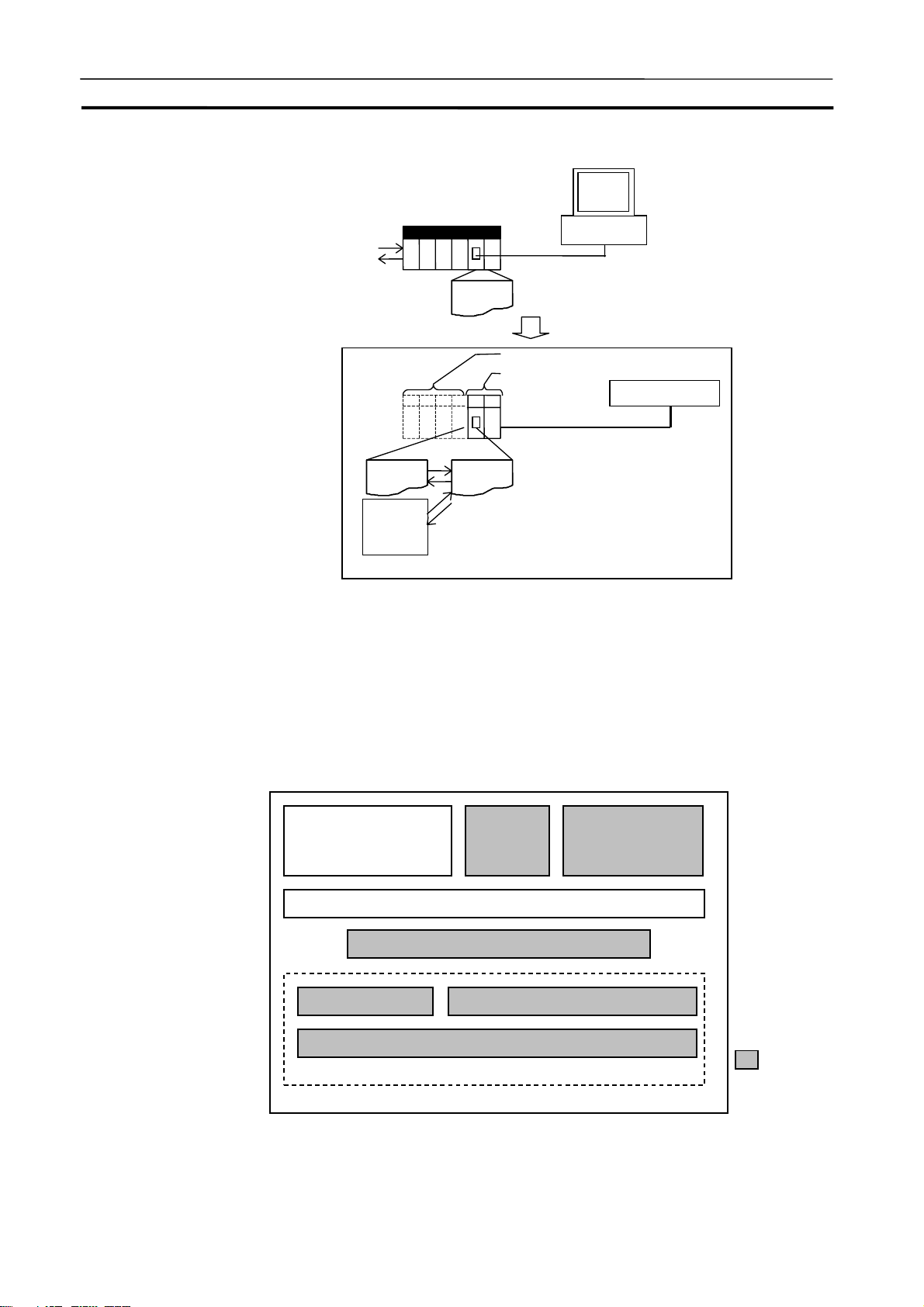
What Is the CX-Simulator? Section 1-1
A
A
CX- Programmer
ctual PLC (CS/CJ/CP Series)
ctual
external I/O
User
program
Inside the computer
Virtual Units
Virtual CPU Unit
CX-Simulator
Debugging
program
Various
input data
generation
tools
External inputs generation
User
program
(CS/CJ/CP Series)
CX- Programmer
1-1-2 Software Configuration of CX-Simulator
The CX-Simulator consists of the Ladder Engine, which is composed of the
virtual CPU Unit and other units (default: only the Simulator Communications
Unit), the FinsGateway (version 2 or higher) Virtual Communications Unit, the
Debugger, and the Virtual External Input Tool.
Computer
Application programs
(e.g. CX-Programmer)
FinsGateway (version 2 or higher)
FinsGateway Virtual Communications Unit
CPU Unit
Virtual CPU Bus Unit
Debugger
Simulator Communications Unit
Virtual External
Input Tool
(See note)
Note:
I/O Conditions
Tool, Data Replay Tool, and
Data Trace
Recording Tool
:CX-Simulator
3
Page 43

What Is the CX-Simulator? Section 1-1
Item Contents
Ladder Engine
FinsGateway (version 2 or higher)
Virtual Communications Unit (See
note.)
Debugger Controls the Ladder Engine and executes various CX-Simulator's own debugging
For virtual external
I/O functions
A platform for CS/CJ/CP-series PLC Emulation
Consists of multiple units.
Default: Consists of the CPU Unit and the Simulator Communications Unit.
CPU Unit A virtual unit corresponding to the actual CPU Unit, in-
cluding application programs (UM1), debugging pro-
grams (UM2), and I/O memory areas.
Simulator Communications
Unit
Connect Simulator Communications Unit in the Ladder Engine with FinsGateway version 2 or higher. Two types are available: Virtual Controller Link Unit and Virtual
Ethernet Unit. The CX-Programmer also performs FINS communications with the Ladder Engine via the Virtual Communications Unit.
functions.
Debugging program (UM2) Possible to simulate I/O operation with a program in the
Command log The log for CX-Programmer's operations (e.g. I/O mem-
Note
The FinsGateway Virtual Communications Unit is different from the FinsGateway
itself. CX-Simulator does not include the FinsGateway itself.
The CX-Simulator's own virtual and general-purpose
communications unit, corresponding to PLC's network
communications unit. Possible to communicate with the
CX-Programmer.
program area for debugging other than the area for ap-
plications (UM1).
ory change, Force set/reset) is saved in a file (Command
log file).
Possible to replay operation for the Ladder Engine using
the Data Replay Tool.
4
Page 44

What Is the CX-Simulator? Section 1-1
A
Item Contents
For virtual external
I/O functions
For network communications
Virtual External Input
Tool
FinsGateway Virtual
comm. Unit/
Simulator
Communications Unit
Data Replay
Tool
I/O Conditions Tool
Data Trace
Recording
Tool
Multipoint
Data Collection Tool
FINS commands send/receive to/from application programs on the
Computers and the CPU Unit of FinsGateway are possible. Screen display of send messages is also possible. FINS commands send is not
possible (receive is possible).
Read data in sequence from Command log file, Data
Trace file, and Data Replay file, and issue FINS commands to the Ladder Engine to regenerate input data.
Change contents of designated I/O memory areas when
the contents satisfy certain conditions.
Possible to input trace data (Data trace file) actually
obtained from PLC to the Ladder Engine using the Data
Replay Tool.
Possible to generate long-term data.
Possible to acquire trace data of more than 50 words from
an actual PLC and to input to the Ladder Engine using the
Data Replay Tool.
1-1-3 Basic Block Diagram
Virtual
external
input
Virtual
External Input
Tool
Computer
CPU Unit
Debugging
program
Application programs
(e.g. CX-Programmer)
FinsGateway
FinsGateway Virtual
Communications unit
Simulator
Communica-
pplication
program
tions unit
5
Page 45

What Is the CX-Simulator? Section 1-1
1-1-4 Summary of CX-Simulator Functions (Comparisons with Actual PLC)
Item Actual PLC CX-Simulator
Hardware CPU Unit
(CS/CJ/CP-series)
System configuration
Peripheral device
CPU Unit basic
functions
Program
Task function Available Available (equivalent)
Basic I/O unit Virtual Basic
Special I/O unit Virtual Special
CPU Bus Unit Virtual CPU
Inner Board Virtual Inner
Power Supply Unit None
CX-Programmer CX-Programmer on the same computer
Programming Console unusable
Single user program Application program
None Debugging program
Virtual CPU Unit (CS/CJ-series)
No opera-
I/O Unit
I/O Unit
Bus Unit
Board
(communicate via FinsGateway Virtual
Communications Unit)
(UM1)
(UM2): For external I/O
data generation
tions (*1).
Registered
for calculating I/O
refresh time
and peripheral servicing time.
*1: Excluding Controller Link
Unit,
Ethernet
Unit, and
Serial
Communications
Unit.
*1: Excluding Serial
Communications
Board
Share I/O memory areas.
6
Page 46

What Is the CX-Simulator? Section 1-1
Item Actual PLC CX-Simulator
CPU Unit basic
functions
Operating mode
I/O memory areas
I/O area allocation
I/O refresh Available None (Only for cycle time calculation. Con-
Peripheral servicing
External input Available Generate virtual external input by one of the
Cycle time Virtual cycle time: Estimated cycle time if
PLC setup Available Available
DIP switch setting
Program mode Stop
Monitor mode and Run
Continuous execution of scan
mode
Minimum Cycle Time Logical cycle time: Substitute cycle time for
set value.
Actual cycle time: Regulate actual execution
time of one cycle on the computer.
None
Scan Run (only one scan)
Continuous Scan Run (one scan at regular
intervals)
Step Run (only one step)
Continuous Step Run (repeat address exe-
cution at regular intervals)
Block Run (Start point, break point, and I/O
break conditions can be set.)
Scan Replay (Return to the start point of the
scan when pausing.)
Operation when power
Reset
turns ON
Available Available
Required PLC unit registration instead (No slot set-
ting)
troller Link Unit, Ethernet Unit, and Serial
Communications Board/Unit performs virtual
operation.)
Available None (Only for cycle time calculation. Con-
troller Link Unit, Ethernet Unit, and Serial
Communications Board/Unit performs virtual
operation.)
followings.
• Overwrite I/O memory areas using the
debugging program.
• Issue FINS commands using the com-
mand log and the Data Replay Tool.
• Issue FINS commands using the data
trace file and the Data Replay Tool.
• Issue FINS commands using the data
replay file and the Data Replay Tool.
• Overwrite I/O memory areas using the
I/O Conditions Tool.
operated on the actual CS/CJ/CP-series
CPU (Application program)
Computer cycle time: Actual cycle time on
the computer (Application program + de-
bugging program)
Available Available (By software, some functions only)
7
Page 47

What Is the CX-Simulator? Section 1-1
Item Actual PLC CX-Simulator
Operation of
each unit
Various functions
Network communications unit
Serial Communications
Board/Unit
Other units Available None
Force-set/reset Available Available
Differential
monitor
Data trace Available Available
Change set
value of
timer/counter
Online edit Available Available
Serial communications
Network communications
Available (Ethernet Unit,
Controller Link Unit)
Available Available (Using SYSMAC WAY Host Link
Available Available
Available Available
Available Available (Only message display)
Available Available (Using FinsGateway Virtual
Available (Simulator Communications Unit,
Ethernet Unit, and Controller Link Unit)
System, NT Link, or No-protocol)
Communications Unit, where send/receive
to/from the nodes in the computer.)
8
Page 48

Features Section 1-2
1-2 Features
Using the CX-Simulator with the following features can reduce man-days for
program debugging.
1-2-1 Features
Possible to simulate operation of the Virtual CPU Unit on the computer.
The CX-Simulator simulates operation of the SYSMAC CS/CJ/CP-series CPU
Unit. The operation of programs can be easily checked without an actual PLC
being connected. Using the CX-Simulator combined with the CX-Programmer
allows to develop/debug programs on a single computer.
Easily use the
CX-Programmer on the
same computer
Calculate the virtual cycle
time
Dedicated debugging function
Programs for the Virtual CPU Unit on the CX-Simulator can be seamlessly
debugged with the CX-Programmer that has been used. The powerful
monitoring functions (including those for a ladder diagram window and present values) can be used as they used to be.
Furthermore, when CX-Programmer version 3.0 or higher is used with
CX-Simulator version 1.3, the CX-Simulator can be started and placed online
from the CX-Programmer.
An estimated cycle time for operation on the actual PLC can be obtained as a
virtual cycle time, which is different from an elapsed time on the computer. Use
it as a tentative time for operation on the actual PLC.
Adding dedicated debugging functions to the CX-Simulator enables more
detailed debugging than that of CX-Programmer + actual CS/CJ/CP-series
PLC.
Step Run
Start point, break point, and
I/O break conditions
Scan Replay
Check the number and the
time of executions of each
task
Simulated startup of interrupt tasks
Serial communications
A program can be executed in the unit of instruction. Peripheral servicing
during a stoppage by the address execution enables monitoring of program
being executed.
A program can be executed from any mnemonic code by designating a start
point. Setting multiple break points and break conditions depending on the I/O
memory status enables to pause a program at any point and on any conditions.
Scan Replay returns the program conditions to those just prior to the scan
started. The program can be replayed on the same conditions any times.
Displaying the number and the time of executions of each task will help solve
the bottleneck in executions, reducing the cycle time by re-division of the tasks.
Simulated startup of interrupt tasks at any timing enables to debug interrupt
processes.
In the CX-Simulator, debugging serial communications is possible by: (1) actual communications to an external serial communications device using a
9
Page 49

Features Section 1-2
y
p
COM port on the computer, (2) screen display of send messages, or (3) input/output from/to a file.
Debugger: Screen displa
Computer
Serial Communications Server
FinsGateway
Virtual Communications Unit
(2)
CPU
Unit
Simulator
Communi-
cations Unit
Display send messages
Display the contents of send messages sent by serial communications instructions (No external output is performed.).
Disabling serial communications instructions possible
Disabling serial communications instructions is possible by settings. This
feature will be used when debugging a program section that is not related to
serial communications.
Debugging network communications possible
The CX-Simulator can debug network communications by send/receive of
FINS commands to application programs in the computer or the CPU Unit in
the FinsGateway, or display of send messages (selected by Communications
Settings). Also, the CX-Simulator can receive FINS commands from the external actual PLC or the computer to the Ladder Engine. (Can not send to
external devices.)
(1)
COM
(3)
Files
ort
RS-232C
External
serial communications
device
10
Page 50

Features Section 1-2
A
A
A
A
p
r
Send/receive FINS commands to nodes in the computer
The CX-Simulator can send/receive FINS commands to nodes (the CPU Unit
itself, application programs using FinsGateway, or the CPU Unit for FinsGateway) in the computer using network communications instructions in the
CPU Unit. This capability enables debugging of network communications with
the CPU Unit itself or the CPU Unit for FinsGateway as the tentative communications target.
Computer
Receive external FINS commands possible
pplication programs
FinsGateway
Virtual Communications Unit
CPU
Unit
Communica-
Simulator
tions Unit
pplication programs
CPU Unit
The CX-Simulator can receive external FINS commands from external networked computers or actual PLCs.
Computer
pplication programs
FinsGateway
Virtual Communications Unit
Display FINS send messages
CPU
Unit
Simulator
Communica-
tions Unit
External actual network
ctual PLC or com-
ute
Display FINS messages sent with network communications instructions on the
message display window. (No actual send is executed.)
11
Page 51

Features Section 1-2
Implement virtual external inputs using various methods.
The CX-Simulator can generate/replay virtual external inputs using various
methods to verify program operation.
Replay input operation using
the command log
Replay inputs using traced
data
Replay inputs using the data
reply file
Simulate I/O using a debugging program
Generate inputs using I/O
Condition
Save the history of manual input operation (e.g. I/O set/reset by the
CX-Programmer and change of DM PVs) and settings by application programs, as a command log file. The saved data can be used instead of the input
to the Ladder Engine by replaying using the data replay function as required.
Replay the data of data trace obtained from the actual PLC by the
CX-Programmer or the data monitored via a time chart, as inputs to the Ladder
Engine using the data replay function.
Replay data of the data reply file (a CSV-format text file) as inputs to ladder
engine. The data replay file can be created using commercially available
spreadsheet software (e.g. MS-Excel).
Hold a program to generate debugging data (debugging program) besides
programs for actual applications (application programs). Input data can be
produced using the debugging program. This capability enables to simulate
I/O. (Application programs and the debugging program share the I/O memory
areas.)
When the contents of designated I/O memory area (bits or words) satisfy the
contents of condition expression; the values are set to the designated I/O
memory area after the designated delay time. Multiple expressions can be set.
12
Page 52

Convenient Functions Section 1-3
1-3 Convenient Functions
The CX-Simulator provides the following convenient functions.
Monitor IR/DR
Block Run
Support debugging of application programs on the
computer
Coordinated functions with
commercial software
By Step Run, the contents of IR/DR for each task during ladder diagram execution can be monitored with the CX-Programmer SV monitoring, which has
been difficult to debug.
After setting break points to the mnemonic codes in the Step Run window,
executing the ladder diagram allows to monitor the value before the mnemonic
code is executed.
Any range of a program can be executed by designating the execution start
point (the start pointer) and execution interrupt point (the break pointer).
When developing a monitoring program or a data collection program on the
computer, debugging communications functions was done with the actual PLC
connected. If the CX-Simulator is used together, on the other hand, a single
computer will do all of the debugging. (Valid only for application programs
using FinsGateway.)
Coordinated functions with commercial spreadsheet programs and text editors
allow using familiar software for data collection/display.
• Obtain mnemonic codes in a task.
Refer to 3-9-7 Step Run Window.
• Obtain task information.
Refer to 3-9-8 Task Control Window.
• Create virtual external input data.
Refer to 8-3 Generating Virtual External Inputs.
• Monitor the result by virtual external inputs.
Refer to 8-5 Checking the Result.
• Designate a program for alarm display. (Only for Windows 95/98/Me)
Refer to Console Display Settings in 3-9-4 File Menu.
13
Page 53

Applicable PLC models and Computers Section 1-4
1-4 Applicable PLC models and Computers
1-4-1 Applicable PLC models
The CX-Simulator supports the following PLC (Programmable Controller)
models.
Series CPU Unit Model
CS CS1H-CPU67/66/65/64/63
CS1G-CPU45/44/43/42
CS1H-CPU67H/66H/65H/64H/63H
CS1G-CPU45H/44H/43H/42H
CS1D-CPU67H/65H
CS1D-CPU67S/65S/44S/42S
CJ CJ2H-CPU68/67/66/65/64 (See note 3.)
CJ2H-CPU68-EIP/67-EIP/66-EIP/65-EIP/64-EIP
(See note 3.)
CJ1H-CPU67H-R/66H-R/65H-R/64H-R
CJ1M-CPU23/22/13/12/11
CJ1H-CPU66H/65H/67H
CJ1G-CPU45H/44H/43H/42H
CJ1G-CPU45/44
CP (See note 1.) CP1H-XA@@@@-@
CP1H-X@@@@-@
CP1H-Y@@@@-@
CP1L-M@@@@-@
CP1L-L@@@@-@
NSJ
(Controller Section)
(See note 2.)
Note
1. In this manual, always assume that " CS/CJ-series PLC" also implies
CP-series PLCs unless otherwise specified. When performing simulations for a CP-series PLC, use the instructions for the CS/CJ-series PLC.
Unit version 1.0 or 1.1 of the CP-series CPU Units is equivalent to unit
version 3.0 of the CS/CJ-series CPU Units. Functions added for unit
version 4.0 or later of the CS/CJ-series CPU Units are not supported by
the CP-series CPU Units. Functions not supported by CP-series PLCs,
however, cannot be simulated.
2. In this manual, always assume that "CJ-series PLC" also implies the
Controller Section of an NSJ-series NSJ Controller unless otherwise
specified. When performing simulations for the Controller Section of the
NSJ Controller, use the instructions for the CJ-series PLC.
3. The functions supported for CJ2-series CPU Units correspond to those
for CS/CJ-series Units with unit version 4.0 or later.
G5D (Used for the NSJ5-TQ0@-G5D,
NSJ5-SQ0@-G5D, NSJ8-TV0@-G5D,
NSJ10-TV0@-G5D, and NSJ12-TS0@-G5D)
M3D (Used for the NSJ5-TQ0@-M3D,
NSJ5-SQ0@-M3D, and NSJ8-TV0@-M3D)
14
Page 54

Applicable PLC models and Computers Section 1-4
1-4-2 Computer
The installation procedure for the independent CD-ROM is provided here.
Refer to the CX-One Setup Manual (W463, provided with the CX-One) for the
installation procedure for the CX-One.
Cat. No.
W463 CXONE-AL@@C-
V4/AL@@D-V4
The required RAM memory capacity depends on the size of program created
with the CX-Programmer. CX-Simulator will be slow if run on a computer with
less than the required RAM memory capacity.
Model Manual name Contents
CX-One Setup
Manual
An overview of the
CX-One FA Integrated
Tool Package and the
CX-One installation
procedure
15
Page 55

Operation List Arranged by Purpose Section 1-5
1-5 Operation List Arranged by Purpose
The following lists show the operation for each purpose.
1-5-1 Setting Operation Environment
Purpose Menu or Button to select
Connect the CX-Simulator Debug Console | File Menu | Work CX-Simulator | Connect Simu-
lator
Disconnect the CX-Simulator Debug Console | File Menu |Work CX-Simulator | Disconnect
Simulator
Create a new PLC Select System Status | Setting | Select PLC | Create a new PLC
Open existing PLC Select System Status | Setting | Select PLC | Open existing PLC
Add a PLC unit System Status | Setting | PLC unit Setting
Change UM System Status | Setting | UM Setting
Initialize PLC memory System Status | Initialize PLC
1-5-2 Program Execution
Objective Menu or Button to select
Execute continuously Debug Console | Continuous Run button
Execute a single scan Debug Console | Scan Run button
Scan continuously Debug Console | Continuous Scan Run button
Execute a single step Debug Console | Step Run button
Execute steps continuously Debug Console | Continuous Step Run button
Pause the program execution Debug Console | Pause button
Stop the program Debug Console | Stop button
Repeat scan from the beginning Debug Console | Scan Replay button
Reset Debug Console | Reset button
1-5-3 Program Debugging
Objective Menu or Button to select
Set for Step Run Debug Console | Step Run
Set break points In the above operation, right-click the program address to set a
breakpoint to and set Select BreakPoint when the pop-up menu is
displayed.
Clear the break point In the above operation, right-click the program address to clear a
breakpoint for and select Clear BreakPoint when the pop-up menu
is displayed.
Clear all break points In the above operation, right-click the Step Run window and select
Clear All BreakPoints when the pop-up menu is displayed.
Designate a start point In the above operation, right-click the program address to set a start
point to and set Select Start Point when the pop-up menu is displayed.
Clear a start point In the above operation, right-click the program address to clear a
start point for and select Clear Start Point when the pop-up menu is
displayed.
Stop the program when the content
of I/O memory area meets certain
conditions
Debug Console | I/O Break conditions Setting
16
Page 56

Operation List Arranged by Purpose Section 1-5
1-5-4 Monitor the Status
Objective Menu or Button to select
Display messages System Status | Message Display
Display alarms System Status | Alarm Display
Display cycle time details System Status | Detail
Display each status of the task Debug Console | Task Control
1-5-5 Set Serial Communications Settings
Objective Menu or Button to select
Set Serial Communications settings
Disable Serial Communications
commands
Display the content of output by the
Serial Communications commands
Use an actual RS-232C port on the
computer for Serial Communications
System Status | Set | Double-click the port used for Serial Communications.
In the above operation, set [− (Non)] to the Communications Settings. (default)
In the above operation, set [Message] to the Communications Settings.
In the above operation, set [Actual Communications] to the Communications Settings.
1-5-6 Set Network Communications Parameters
Objective Menu or Button to select
Set network communications parameters
Change the node number of the
network communications unit
Disable network communications
commands
Display the content of output by
network communications commands
Issue a network communications
command to the designated node
in the computer
System Status | Set | Double-click the unit used for network communications
In the above operation, change the value of FINS node address.
In the above operation, set [− (Non)] to the Communications Settings. (default)
In the above operation, set [Message] to the Communications Settings.
In the above operation, set [Local] to the Communications Settings.
1-5-7 Execute Virtual External Input
Objective Menu or Button to select
Set a program area for debugging System Status | Set | UM Setting
Invoke data for data replay from a
file
Set a command log Debug Console | Replay Menu | Command Log | set
Start a command log Debug Console | Replay Menu | Command Log | Start
Exit a command log Debug Console | Replay Menu | Command Log | Stop
Display command log data Debug Console | Replay Menu | Command Log | View Log
Set I/O Condition Debug Console | Replay Menu | I/O Condition | File Menu | Set
Execute I/O Condition Debug Console | Replay Menu | I/O Condition | Start
Debug Console | Replay Menu | Data Replay
17
Page 57

Comparison of the CX-Simulator and SYSMAC CS/CJ-series PLCs Section 1-6
1-6 Comparison of CX-Simulator and SYSMAC CS/CJ-series PLCs
In the CX-Simulator, the part implementing PLC functions (CS/CJ CPU Unit
and Communications Unit) is called the Ladder Engine. The following list
compares SYSMAC CS/CJ-series PLC with and the Ladder Engine of the
CX-Simulator. Take notice of the followings when using the CX-Simulator.
Item CS/CJ-series PLC CX-Simulator
Program
structure
I/O allocation "Create I/O table"
Online editing CS/CJ-series PLC:
CS/CJ-series PLC:
Multiple tasks (pro-
grams) vs.
CX-Simulator: Mul-
tiple program areas/
multiple tasks
CS-series PLC:
Required vs.
CX-Simulator: Own
settings required
RUN /MONITOR
mode vs.
CX-Simulator:
Continuous run
(Run/Monitor mode),
Pause (Scan Run,
Step Run, Break
point, and I/O break
condition)
In CS/CJ-series PLCs, the program is divided into
tasks (cyclic tasks) that are executed in order when
they are enabled.
CS/CJ-series PLCs support up to 32 cyclic tasks (128
cyclic tasks for CJ2-series PLCs), 32 I/O interrupt
tasks, 2 scheduled interrupt tasks, 1 power OFF in-
terrupt task, and 256 external interrupt tasks.
In CS/CJ-series PLCs, word allocation does not de-
pend only on slot position, and it is not necessary to
allocate words to an empty slot. If a Unit requires
several words, those words can be allocated.
When a CS-series PLC is being used, the I/O Table
Registration operation must be executed. If it is not
executed, the CPU Unit will not recognize each Basic
I/O Unit, Special I/O Unit, and CPU Bus Unit that has
been installed.
In CS/CJ-series PLCs, peripheral servicing is per-
formed for the cycle time of one cycle to multiple cycles
(where the cycle time is extended up to 90 ms per one
cycle).
In the CX-Simulator, the program is
divided into two areas: the program
area for applications (UM1) and for
debugging (UM2). One program area
corresponds to a CS/CJ's UM and
accesses the same I/O memory area.
Usually only UM1 is used.
However, task numbers, subroutine
numbers, and block program numbers
can not overlap between program
areas.
The following functions that are sup-
ported by CS/CJ-series Ver.2.0 and
CP-series CPU Units cannot be used.
• Task Transfer to PLC
• Task Read Protection (Functions
as UM read protection.)
The I/O table is not used.
In the PLC Setup wizard or PLC Unit
Setting, the unit for own use is selected.
Although the machine number and the
unit number are set, the slot is not set.
The I/O refresh time is calculated
based on the selected units.
In the CX-Simulator, the process is
completed within one cycle. There is
no limit for the maximum extension time
per one cycle.
When in Continuous Run, the periph-
eral servicing performs the process.
When the ladder program is in pausing,
the peripheral servicing is always
working, enabling online editing.
However, if online editing is performed
during the program execution, The
setting of [System Status Setting] |
[Settings] | [PLC Operation Setting] |
[Run the program from the top when
online editing during Step Run] will
cause the following operation.
Not checked: Enter the Program mode.
Checked: Scan Replay
18
Page 58

Comparison of the CX-Simulator and SYSMAC CS/CJ-series PLCs Section 1-6
Item CS/CJ-series PLC CX-Simulator
Data
Areas
Data Areas
I/O Area CIO 0000 to CIO 0319 Not allocated actually even if the
CIO
Area
Special
I/O Unit
Area
DeviceNet
Area and
SYSMAC
BUS Area
PLC Link
Words
Optical I/O
Unit and
I/O Terminal Area
Link Relay
Area (LR)
Work/
Internal
I/O area
Work Area (WR) Work Area: W000 to W511 Same as shown at left.
Temporary Relay
Area
Holding Relay
Area(HR)
Auxiliary Relay
Area (AR)
DM Area DM Area
EM Area CS/CJ-series CPU Units:
Timer Area T0000 to T4095 Same as shown at left.
Counter Area C0000 to C4095
Task Flag Area CS/CJ-series CPU Units: TK0 to TK31
CIO 2000 to CIO 2959 Only Serial Communications Units
DeviceNet Area:
CIO 0050 to CIO 0099,
CIO 0350 to CIO 0399
SYSMAC BUS Area:
CIO 3000 to CIO 3049
CIO 0247 to CIO 0250 and A442
I/O Terminal Area:
CIO 3100 to CIO 3131
Link Area: CIO 1000 to CIO 1199 Not used.
Internal I/O Area:
CIO 1200 to CIO 1499
CIO 3800 to CIO 6143
TR 00 to TR 15 Same as shown at left.
H 000 to H 511 Same as shown at left.
Auxiliary Area: A 000 to A 959
For CJ2-series PLCs: A 000 to A 1471 and
A 10000 to A 11535
D00000 to D32767
D20000 to D29599 are used by Special I/O Units,
D30000 to D31599 are used by CPU Bus Units,
and D32000 to D32099 are used by Inner
Boards.
The Error Log is stored in A100 to A199 and the
PLC Setup is stored in the Parameter Area (not a
part of I/O Memory).
EM Area E00000 to E32767 (13 banks max.)
CJ2-series CPU Units:
EM Area E00000 to E32767 (25 banks max.)
The EM Area in the CS/CJ-series CPU Unit can
be accessed directly by most instructions. (There
is no EM Area in the CP-series CPU Unit.)
Regular instructions can access data in the
current bank or any other bank.
Part of the EM Area can be converted for use as
a file memory.
(Timer and counter numbers are independent.)
CJ2-series CPU Units: TK0 to TK127
unit is set.
and Network Communications
Units are allocated.
Not allocated actually even if the
unit is set.
Same as shown at left.
Same as shown at left.
(Refer to 9-3 I/O Memory Alloca-
tion for details.
Same as shown at left.
Same as shown at left.
Same as shown at left.
Same as shown at left.
19
Page 59

Comparison of the CX-Simulator and SYSMAC CS/CJ-series PLCs Section 1-6
Item CS/CJ-series PLC CX-Simulator
Data Areas Index Registers IR0 to IR15 Same as shown at left.
PLC setup Special Area In the CS/CJ/CP-series CPU Unit, the PLC Setup
Instruction
variations
Instruction
variations
Instruction operand data
format
Specifying operands requiring
multiple words
Data Registers DR0 to DR15 Same as shown at left.
Arithmetic Flags
(such as RE and
EQ)
Clock Pulses Clock Pulses:
Up-differentiation Available Same as shown at left.
Downdifferentiation
Immediate
refreshing
Up-differentiation
and immediate
refreshing
Downdifferentiation and
immediate refreshing
Condition Flags:
In the CS/CJ-series CPU Unit these Flags are in
a separate area and are specified by labels
rather than addresses. With the
CX-Programmer, these are specified using
global symbols, such as “P_Instr_Error “ and
“P_Equals." With a Programming Console, they
are specified using “ER,” “=,” etc.
In the CS/CJ-series CPU Unit these pulses are in
a separate area and are specified by labels such
as “1s” and “0.1s” rather than addresses.
is not stored in the DM Area, but a separate area
(the Parameter Area) which is not a part of I/O
memory.
The PLC Setup is edited with CX-Programmer in
a table format and user-friendly dialogue.
Individual PLC Setup addresses can also be
edited with a Programming Console.
Available for LD, AND, OR, RSET, and SET Same as shown at left.
Available for LD, LD NOT, AND, AND NOT, OR,
OR NOT, OUT, OUT NOT, RSET, SET, KEEP,
DIFU, DIFD, CMP, CPS, and MOV
Available for LD, AND, OR, RSET, SET, and
MOV
Available for LD, AND, OR, RSET, and SET Same as shown at left.
Basically operands are specified in binary.
In XFER(070), for example, the number of words
is specified in binary (0001 to FFFF or 1 to
65,535 decimal). Specifying data in binary increases the setting range about six-fold.
If an operand requiring multiple words is specified at the end of an area so that there are not
enough words left in the area for the operand, the
instruction can be executed and the Error Flag
will not turn ON. The program, however, is
checked when transferred from the
CX-Programmer to the CPU Unit and cannot be
transferred with incorrect operand specifications.
Such programs also cannot be read from the
CPU Unit.
Same as shown at left.
(The Programming Console can
not be used.)
Same as shown at left.
Same as shown at left.
(The Programming Console can
not be used.)
Refer to 9-3 I/O Memory Alloca-
tion.
Same as shown at left.
(Immediate refreshing is not performed.)
Same as shown at left.
(Immediate refreshing is not performed.)
(Immediate refreshing is not performed.)
Same as shown at left.
Same as shown at left.
20
Page 60

Comparison of the CX-Simulator and SYSMAC CS/CJ-series PLCs Section 1-6
Item CS/CJ-series PLC CX-Simulator
Instructions
Sequence Input Equivalent
Sequence Output Equivalent
Sequence Control Equivalent Equivalent (The MILH and MILR
instructions, however, cannot be
used to control the ON/OFF status
of interlocks by forcing ON/OFF
the bit specified for the second
operand. The interlocks must be
controlled through the execution
condition of the instruction.)
Timer/Counter Equivalent (TRSET is equivalent only for CJ2-series PLCs.)
Comparison Equivalent
Data Movement Equivalent
Data Shift Equivalent
Increment/Decrement Equivalent
Symbol Math Equivalent
Conversion Equivalent (GRAY_BIN, GRAY_BINL, BIN_GRAY, BIN_GRAYL are
equivalent only for CJ2-series PLCs.)
Logic Equivalent
Special Math Equivalent
Floating-point Math Equivalent (A rounding error may occur.)
Table Data Processing Equivalent
Tracking MAXL, MINL, MAXF, MINF, MAXD, MIND are equivalent only for
CJ2-series PLCs.
Data Control Equivalent (Nothing is executed for PID.)
Subroutines Equivalent
Interrupt Control Equivalent
Step Equivalent
Basic I/O Unit IORF, IORD, IOWR, TKY, HKY,
7SEG, and DSW available.
Serial Communications PMCR, and PMCR2 available.
TXD, RXD, and STUP available.
Network SEND, RECV, and CMND available.
CSND available.
File Memory Equivalent
Display Equivalent (Messages of Programming Console are displayed on the
screen.)
High-Speed Counter Pulse
Control Instructions (CJ1M
only)
Clock Equivalent (With the CX-Simulator, however, even if the time in the PLC is
Debugging Equivalent
INI, SPED, PRV, PRV2, CTBL,
PULS, ACC, PLS2, ORG, and PWM
instructions
adjusted with the DATE instruction, it will be automatically corrected to the
time in the computer at the end of the cycle in which the DATE instruction is
executed.)
Nothing is executed for the IORF,
IORD, or IOWR instructions.
Nothing is executed for PMCR or
PMCR2.
TXD, RXD, and STUP operate
differently depending on communications parameters.
TXDU2, and RXDU2 operate only
for CJ2-series PLCs.
SEND, RECV, and CMND operate
differently depending on communications parameters.
Nothing is executed for CSND.
SEND2, RECV2, and CMND2
operate only for CJ2-series PLCs.
Nothing is executed for the instructions listed at the left.
21
Page 61

Comparison of the CX-Simulator and SYSMAC CS/CJ-series PLCs Section 1-6
Failure
Diagnosis
Special Equivalent
Block
Programming
Text String Processing Equivalent
Task Control Equivalent
Equivalent (Messages of Programming Console are displayed on the
screen.)
Equivalent
Note
TIM/TIMH (Timer No. 2,048 to 4,095), TTIM, TIML, MTIM, and FPD will not operate
normally when the cycle time is 100 ms or longer. Make sure that the cycle time is
different from that of the CS/CJ/CP-series CPU Unit if set as the computer cycle time.
Item CS/CJ-series PLC CX-Simulator
I/O comment storage In the CS/CJ-series PLCs, I/O comments can be
stored in Memory Cards as I/O comment files.
Battery installation The battery is not installed when the PLC is
shipped from the factory. Install the provided
battery before using the PLC.
Clock function When the battery is installed in the PLC, the clock
will begin from an arbitrary value. Set the clock
with a Programming Device or the DATE(735)
instruction.
Memory
Cards and
Memory
Cassettes
I/O Memory Any range of I/O Memory can be saved as a file
in a Memory Card (flash ROM) or EM file memory
with a Programming Device (including Pro-
gramming Consoles) or the instruction provided
for this operation. A Programming Device or
instruction can be used to read the data back
from file memory.
These operations can also be performed with
FINS commands.
User program The entire program can be saved as a file in a
Memory Card (flash ROM) or EM file memory
with a Programming Device (including Pro-
gramming Consoles) or the instruction provided
for this operation. A Programming Device or
instruction can be used to read the program back
from file memory.
These operations can also be performed with
FINS commands.
Same as shown at left.
(The destination is the hard disk of
the computer.)
Not available.
Adjusted to the clock of the computer when the CX-Simulator is
started.
Same as shown at left.
(The hard disk of the computer is
used as memory cards or EM file
memory.)
Batch save/read enable to
save/read I/O memory, PLC Setup,
UM, and other settings as the own
files.
Same as shown at left.
(The hard disk of the computer is
used as memory cards or EM file
memory.)
Batch save/read enable to
save/read I/O memory, PLC Setup,
UM, and other settings as the own
files.
22
Page 62

Comparison of the CX-Simulator and SYSMAC CS/CJ-series PLCs Section 1-6
Item CS/CJ-series PLC CX-Simulator
Serial communications
(peripheral
port or
RS-232C
ports)
Mode
Baud
rate
Peripheral port
RS-232C
port
USB port Peripheral bus, EtherNet/IP (CJ2-series PLCs
Peripheral port
Host Link, peripheral bus, NT Link (1:N), (Programming Console and peripheral bus are
automatically recognized.)
(No-protocol is not possible for the peripheral
port.)
Host Link, peripheral bus, NT Link (1:N), and
No-protocol.
(1:1 links and peripheral bus are not supported
for the RS-232C port.)
only)
300/600/1,200/2,400/4,800/9,600/19,200/
38,400/57,600/115,200 bps
(Baud rates of 38,400/57,600/115,200 bps are
not standard for RS-232C.)
The peripheral port is not supported.
Host Link, No-protocol, and NT
Link are supported.
The USB port is not supported.
The peripheral port is not supported.
RS-232C
port
Network communications timing Performed as peripheral servicing. When in Continuous Run, per-
Interrupt control modes If an interrupt occurs during Host Link servicing,
Remote I/O servicing, Special I/O Unit servicing,
or execution of an instruction, that process will be
stopped immediately and the task will be executed instead.
Startup mode The CS/CJ-series CPU Unit will start in
PROGRAM mode if the Startup Mode is set in
the PLC Setup to PRCH: Switch Setting on
Programming Console (default setting) and the
CPU Unit is started without a Programming
Console connected.
Same as shown at left.
(The actual speed will vary depending on the hardware of the
computer.)
formed as peripheral servicing.
When in pausing, the network
communications processing is
performed.
Interrupt is prohibited during peripheral servicing and execution of
an instruction.
Only "PRCH: Switch Setting on
Programming Console" (default
setting) (Will start in PROGRAM
mode as a Programming Console
is not connected.)
23
Page 63

Comparison of the CX-Simulator and SYSMAC CS/CJ-series PLCs Section 1-6
24
Page 64

SECTION 2
Setup
2-1 Installing and Uninstalling the Software ....................................................................................26
2-1-1 Required Software.......................................................................................................... 26
2-1-2 Preparations.................................................................................................................... 26
2-1-3 Precautions ..................................................................................................................... 27
2-1-4 Installing the CX-Simulator ........................................................................................... 28
2-1-5 Uninstalling the CX-Simulator....................................................................................... 34
25
Page 65

Installing and Uninstalling the Software Section 2-1
2-1 Installing and Uninstalling the Software
2-1-1 Required Software
The following software must be installed on the same computer to use the
CX-Simulator.
1,2,3…
Forms of the CX-Simulator
1. CX-Simulator
2. CX-Server (communications driver)
The CX-Simulator is available both on an independent CD-ROM and on the
CX-One FA Integrated Tool Package CD-ROM. The CX-Simulator is the same
in either case.
The installation procedure for the independent CD-ROM is provided here.
Refer to the CX-One Setup Manual (W463, provided with the CX-One) for the
installation procedure for the CX-One.
Cat. No. Model Manual name Contents
W463 CXONE-AL@@C-
V4/AL@@D-V4
CX-One
Setup Manual
An overview of the CX-One FA
Integrated Tool Package and
the CX-One installation procedure
2-1-2 Preparations
Note
1,2,3…
Note
If the CX-Simulator was previously installed from the CX-One and it is necessary to install it from the individual CX-Simulator CD-ROM, always
uninstall the CX-Simulator using the following procedure before installing it
from its individual CD-ROM. The CX-Simulator will not operate properly if it is
installed without first uninstalling it.
1. Insert the CX-One installation disk 1 into the CD-ROM drive.
2. Select the Modify Option to enable modifying the Support Software that is
installed.
3. In the Select Features Dialog Box, clear the selection of only the
CX-Simulator. Do not change any other selections.
4. Continue by following the instructions in the dialog boxes to modify the
installation and uninstall CX-Simulator.
5. Once the CX-Simulator uninstallation process has been completed, place
the individual CD-ROM disk for the CX-Simulator into the CD-ROM drive
and install the CX-Simulator. (See note.)
If the version of the CX-Server bundled on the individual CX-Simulator
CD-ROM is lower than the version of the CX-Server bundled with the
CX-One, install only the CX-Simulator and NOT the CX-Server. (A message
will be displayed if the version is lower.) If a version of CX-Server that is
lower than the version with the CX-One is installed, the CX-One will not operate properly.
26
Page 66

Installing and Uninstalling the Software Section 2-1
Uninstalling the Previous Version of CX-Simulator
Always uninstall the previous version of the CX-Simulator before installing a
new version.
1,2,3…
1. Start Add/Remove Applications* from the control panel.
2. Select CX-Simulator from the dialog box.
3. Click the Change/Remove Button. The CX-Simulator will be uninstalled.
*This is called Add/Remove Programs in Windows XP.
This is called Programs and Features in Windows Vista and Windows 7.
2-1-3 Precautions
Note
The Installer manages the version and driver for the CX-Server. If the
CX-Server installed on the computer is old, the Installer will automatically
update the CX-Server. If the CX-Server Driver Management Tool or the
CX-Server is uninstalled from the control panel, it may no longer be possible
to use certain Units. Do not uninstall the CX-Server Driver Management Tool
or the CX-Server from the control panel.
This section describes the procedures involved in the installation of
CX-Simulator on a standard workstation running Microsoft Windows 2000,
XP, Vista, or Windows 7.
• Close all programs running on Windows before starting the installation
procedure.
• Do not stop the setup process in the middle. Copied files may remain in the
installation directory.
• Do not turn OFF or reset the computer in the middle of the installation
process. Computer data may become corrupted.
• The administrator or a user with administrator rights must perform the in-
stallation. Other users will not have sufficient write permissions and access
errors will occur.
• With Windows 2000, always use service pack 4 or later. The service pack
27
Page 67

Installing and Uninstalling the Software Section 2-1
can be confirmed by selecting Start - Settings - Control Panel - System.
The service pack will be displayed under System on the General Tab Page
of the System Properties Dialog Box. If a service pack is not displayed, no
service pack has been installed. Refer to Microsoft’s website for service
pack installation methods.
• It may be necessary to restart Windows after finishing the installation. If
required, restart Windows according to the messages displayed by the In-
Note
staller.
Internet Explorer version 5.0 or higher must be installed in advance to use
the CX-Server Installer. Install Internet Explorer version 5.0 in advance if it is
not already installed.
2-1-4 Installing the CX-Simulator
1,2,3…
1. Insert the CX-Simulator installation disk (CD-ROM) into the CD-ROM drive.
2. The setup program will start automatically and the Choose Setup Lan-
guage Dialog Box will be displayed.
The language of the operating system running on the computer will be selected automatically.
If the above dialog box is not displayed, double-click the CD-ROM drive from
the Explorer to display it.
Select the language to be installed and click the OK button.
3. A splash window for the CX-Simulator will be displayed, followed by the
Setup Wizard.
28
Page 68

Installing and Uninstalling the Software Section 2-1
Click the Next Button.
4. The License Agreement Dialog Box will be displayed.
Read the license agreement completely and if you accept all of the terms,
select the I accept the terms of the license agreement Option and click the
Next Button.
5. The User Information Dialog Box will be displayed.
29
Page 69

Installing and Uninstalling the Software Section 2-1
The default names registered in the computer will be entered for the user
name and company name. Enter the license number and click the Next
Button. The license number is given on the Software License/Registration
Card provided with the product.
6. The Select Features Dialog Box will be displayed.
30
Page 70

Installing and Uninstalling the Software Section 2-1
Note
Select one of the following, then click the Next Button.
CX-Programmer Online Connection
Select this set-up type to monitor or debug ladder programs within
CX-Simulator only from CX-Programmer. In this case, CX-Programmer
must be installed on the computer in advance.
FinsGateway Application Connection
Select this set-up type for either of the following cases.
When connecting with an application (such as PLC Reporter) that uses
FinsGateway communications.
When connecting with an application that sends and receives FINS commands via Controller Link or Ethernet from another computer. In this case,
however, a virtual communications unit for FinsGateway must be installed
in advance.
Even with one of the set-ups above selected, it is still possible to start-up and
make an online connection from CX-Programmer, and to conduct serial
communications using the serial port of the computer.
7. The Choose Destination Location Dialog Box will be displayed.
When installing for CX-Programmer online connection, this dialog box is
not displayed. The installation is automatically done in the same directory
in which the CX-Server has been installed.
Confirm the installation destination, then click the Next Button.
8. The Select Program Folder Dialog Box will be displayed.
31
Page 71

Installing and Uninstalling the Software Section 2-1
Designate the location to add a new shortcut to the program folder of the
Start menu. Then click the Next Button.
9. The Ready to Install the Program Dialog Box will be displayed.
32
Click the Install Button.
The installation will be initiated by the installation program.
To check the installation details, or to make changes, click the Back Button.
To cancel the installation, click the Cancel Button.
Page 72

Installing and Uninstalling the Software Section 2-1
10. The following dialog box will be displayed when the installation is complete. Click the Finish Button.
If it is necessary to restart the computer, the following dialog box will be
displayed.
Click the Finish Button. If a check mark has been entered in the Yes, I
want to restart my computer now Option, the computer will be restarted.
33
Page 73

Installing and Uninstalling the Software Section 2-1
11. After the computer has been restarted, a Read me file will be displayed.
2-1-5 Uninstalling the CX-Simulator
Use the following procedure to uninstall the CX-Simulator from a computer.
1,2,3…
1. Select Start - Settings - Control Panel - Add/Remove Applications*.
2. Select CX-Simulator from the dialog box.
3. Click the Change/Remove Button.
*This is called Add/Remove Programs in Windows XP.
This is called Programs and Features in Windows Vista and Windows 7.
34
4. The following dialog box will be displayed to confirm that you want to
completely remove CX-Simulator. Click the OK Button to uninstall.
Page 74
Installing and Uninstalling the Software Section 2-1
5. When the uninstallation is complete, the following dialog box will be displayed. Click the Finish Button.
35
Page 75

Installing and Uninstalling the Software Section 2-1
36
Page 76

SECTION 3
Basic Operation
3-1 Starting Methods for the CX-Simulator...................................................................................... 38
3-2 Starting and Going Online from the CX-Programmer................................................................ 39
3-2-1 Basic Window ................................................................................................................ 40
3-2-2 Pop-up Menu .................................................................................................................. 40
3-2-3 Disconnecting the CX-Simulator from the CX-Programmer ......................................... 41
3-2-4 Exiting the CX-Simulator from the CX-Programmer .................................................... 41
3-2-5 Going Online with the CX-Simulator Already Started from CX-Simulator Menus ...... 41
3-3 Starting and Exiting from CX-Simulator Menus........................................................................ 42
3-3-1 Starting CX-Simulator.................................................................................................... 42
3-3-2 Exiting CX-Simulator..................................................................................................... 43
3-4 Outline of Operation Procedure.................................................................................................. 44
3-4-1 Method 1: Starting and Going Online from the CX-Programmer
(CX-Programmer Version 3.0 or Higher)...................................................................... 44
3-4-2 Method 2: Starting from the CX-Simulator Menus........................................................ 45
3-5 Creating a New PLC................................................................................................................... 48
3-5-1 PLC Setup Wizard..........................................................................................................48
3-5-2 Open Existing PLC.........................................................................................................55
3-5-3 Folder Used in CX-Simulator......................................................................................... 56
3-6 Each Part of the Windows .......................................................................................................... 58
3-6-1 Basic Windows Arrangement......................................................................................... 58
3-6-2 Basic Windows Transition ............................................................................................. 59
3-7 System Status Setting Window................................................................................................... 60
3-7-1 System Status Setting Window ...................................................................................... 60
3-7-2 Setting Menu of System Status Setting .......................................................................... 64
3-7-3 Register PLC Unit .......................................................................................................... 64
3-7-4 UM Settings.................................................................................................................... 65
3-7-5 PLC Clock Settings ........................................................................................................67
3-7-6 PLC Operation Settings.................................................................................................. 68
3-7-7 Initializing PLC .............................................................................................................. 69
3-7-8 Message Display Window.............................................................................................. 69
3-7-9 Alarm Display ................................................................................................................ 70
3-8 Connecting to the CX-Programmer Version 2.1 or Lower......................................................... 71
3-8-1 Work CX-Simulator Window ........................................................................................ 72
3-8-2 How to Connect with CX-Programmer.......................................................................... 73
3-9 Debug Console Window............................................................................................................. 76
3-9-1 Debug Console Window ................................................................................................ 76
3-9-2 Menu List of CX-Simulator Debug Console.................................................................. 78
3-9-3 Outline of Basic Operation for Debug Console Menu ................................................... 79
3-9-4 [File] Menu..................................................................................................................... 80
3-9-5 [Replay] Menu................................................................................................................ 84
3-9-6 [Help] Menu ................................................................................................................... 93
3-9-7 [Step Run] Window........................................................................................................ 94
3-9-8 Task Control Window .................................................................................................... 96
3-9-9 I/O Break Condition Settings Window........................................................................... 97
37
Page 77

Starting Methods for the CX-Simulator Section 3-1
3-1 Starting Methods for the CX-Simulator
There are two different methods that can be used to start the CX-Simulator.
Method 1: Starting and Going Online from the CX-Programmer
Select [Simulator Online Connection] from the [Simulation] menu.
Method 2: Starting from the CX-Simulator Menus
The CX-Simulator can be started separately from the CX-Simulator menus.
Settings are made using the PLC Setup Wizard, operations are performed on
the Simulator Connections Window, and an online connection is made from
the CX-Programmer.
Note
Method Method 1: Starting and Going Online
Main Differences
System
Status
Settings
Status
Display
Program
Execution
Operation
Debugging
Operation
Replay
Connection with Application Programs Not supported. Supported. Work CX-Simulator Window
Select PLC Supported. Automatically selected
PLC Unit Registration Not supported.
Register Network Communications
Serial Communications
Setting
UM Settings Not supported.
PLC Clock Settings Supported.
PLC Operation Settings Supported.
Initialize PLC Not supported.
Status Display LED
Cycle Time Display
Operation Mode
UM Settings Display
Message Display
Alarm Display
Detail Status Display
Run
Scan Run
Continuous Scan Run
Step Run
Continuous Step Run
Pause
Stop
Scan Replay
Reset
Show Step Run
Task Control
I/O Break Condition Setting
Read All Not supported. Supported.Files
Save All Not supported. Supported.
I/O Condition Operation Supported. Supported.
Data Replay Supported.
Command Log Not supported. Supported.
Method 1 can be used to make an online connection for a CX-Simulator already started using the CX-Simulator menus for method 2.
The differences between these two methods are listed in the following table.
•
Used when serial communications
and connections to FinsGateway applications will not be performed.
•
Used when a PLC data directory will
not be specified and UM or I/O memory data saved or read.
Not supported.
Not supported.
Not supported. Supported. System Status Setting Window
Supported.
Supported.
from the CX-Programmer
according to
CX-Programmer project.
Pop-up Menus
Toolbar: Execution
Operation
Toolbar: Debugging
Operation
Pop-up Menus
Method 2: Starting from the CX-Simulator
•
•
Supported. System Status Setting Window
Supported.
Supported.
Supported.
Menus
Used when serial communications or
connections to FinsGateway applications
will be performed.
Used when a PLC data directory will be
specified and UM or I/O memory data
saved or read.
Toolbar: Execution Operation
Debug
Toolbar: Debugging Operation
Menus
Console
Window
38
Page 78

Starting and Going Online from the CX-Programmer Section 3-2
3-2 Starting and Going Online from the CX-Programmer
When using CX-Programmer version 3.0 or higher, the CX-Simulator can be
started and placed online from the CX-Programmer. As soon as online status
is reached, program transfer operations to the CX-Simulator can be performed.
Note
1,2,3…
The CX-Simulator must be started from the CX-Simulator menus (see 3-3
Start and Exit) to use a computer serial port from the CX-Simulator or to per-
form communications via a FinsGateway network from the CX-Simulator.
The procedure used to start the CX-Simulator from the CX-Programmer and
create an online connection is described below. The CX-Programmer (version
3.0 or higher) must be installed on the computer in advance.
1. Start the CX-Programmer, create a new project, and set a CS/CJ-series
PLC as the PLC model, or load an existing project with a CS/CJ-series
PLC set as the PLC model.
Note
Perform the following steps to automatically download the program to the
CX-Simulator after creating an online connection from the CX-Programmer.
a) Select [Tool] | [Option] from the main menu on the CX-Programmer.
b) Click the [PLCs] tab. The following window will be displayed.
c) Place a checkmark by [Automatically Transfer Program to Simulator]
and click the [OK] button.
39
Page 79

Starting and Going Online from the CX-Programmer Section 3-2
2. Select [Simulation] | [Simulator Online Connection] from the main menus.
The CX-Simulator will be started automatically for the PLC model specified
in the selected project and an online connect will be made unrelated to the
communications settings in the current project.
Note
If [Automatically Transfer Program to Simulator] was selected in the tool options, a dialog box for transferring the program to the CX-Simulator will appear
and the program will be transferred to the CX-Simulator when the [OK] button
is clicked.
3-2-1 Basic Window
If an online connection to the CX-Simulator is created from the
CX-Programmer, the following [Debug Console] window will be displayed for
the CX-Simulator.
Title Bar
Toolbar
Name Function
Title bar The title is displayed along with the current cycle count.
The cycle count will be displayed in brackets [ ] when
the cycle has been paused.
Toolbar Click an icon to select a function. Refer to 3-9 Debug
Console Window for details.
Note
The main menus will not be displayed when an online connection to the
CX-Simulator has been created from the CX-Programmer.
3-2-2 Pop-up Menu
The following pop-up menu will be displayed when the right mouse button is
clicked anywhere in the [Debug Console] window except on the title bar or on
an icon that can be selected.
When an online connection to the CX-Simulator has been created from the
CX-Programmer, this pop-up menu is used to select the following functions
instead of using the main menus.
40
Page 80

Starting and Going Online from the CX-Programmer Section 3-2
Name Function
I/O Condition Starts the I/O Condition Operation Tool. Refer to I/O Condition under
3-9-5 [Replay] Menu for details.
Data Replay Sets Data Replay and starts the Data Replay Tool. Refer to Data Re-
play under 3-9-5 [Replay] Menu for details.
PLC Clock Settings Sets the cycle time mode, the interval for continuous run, and others.
Refer to 3-7-5 PLC Clock Settings for details.
PLC Operation Settings Sets the WDT disable, DIP switches, and others. Refer to 3-7-6 PLC
Operation Settings for details.
Initialize PLC Initialize the I/O memory of PLC.
Always on Top Pins the CX-Simulator windows on top.
Help Displays help.
3-2-3 Disconnecting the CX-Simulator from the CX-Programmer
Use the following procedure to end the online connection to the CX-Simulator
from the CX-Programmer.
Select [Simulation] | [Simulator Online Connection] from the main menus. The
CX-Simulator will go offline and the CX-Simulator dialog box will return to the
task tray. The CX-Simulator will automatically return to PROGRAM mode. The
CX-Simulator dialog box will be restored to the original position if [PLC] |
[Simulator Online Connection] is selected from the main menus of the
CX-Programmer again.
3-2-4 Exiting the CX-Simulator from the CX-Programmer
You can exit the CX-Simulator using any of the following steps.
• Select [Exit Simulator] from the [Simulation] menu in the main menus of the
CX-Programmer.
• Close the CX-Programmer project.
• Exit the CX-Programmer.
3-2-5 Going Online with the CX-Simulator Already Started from
CX-Simulator Menus
[Simulator Online Connection] can be selected to go online with the
CX-Simulator even if the CX-Simulator has already been started from
CX-Simulator menus. To do this, the CX-Simulator Communications Unit must
be the Controller Link.
1,2,3…
1. Open a project on the CX-Programmer and set the PLC model to the same
model as the one used to start the CX-Simulator.
2. Select [Simulation] | [Simulator Online Connection] from the main menus of
the CX-Programmer. An online connect will be made unrelated to the
communications settings in the current project.
41
Page 81
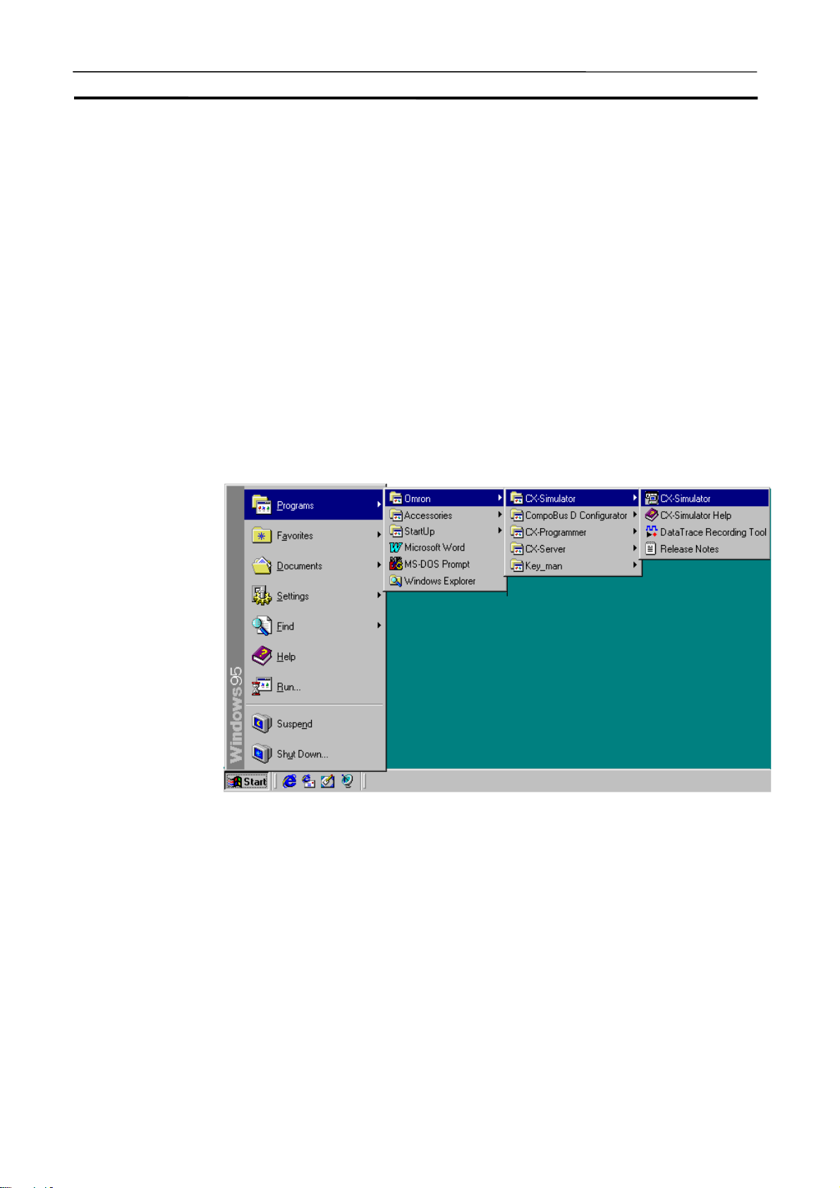
Starting and Exiting from CX-Simulator Menus Section 3-3
3-3 Starting and Exiting from CX-Simulator Menus
This section describes how to start and exit the CX-Simulator.
Note
3-3-1 Starting CX-Simulator
1,2,3…
Use this method to start the CX-Simulator in the following cases:
• When the CX-Simulator performs serial communications using a computer’s
serial port.
• When performing communications via a FinsGateway network.
• When specifying a PLC data directory and saving or reading UM or I/O
memory data for the Ladder Engine.
The following shows the CX-Simulator’s startup procedure.
3. After clicking the [Start] button on the task bar, select [program] | [Omron] |
[CX-One] | [CX-Simulator] as shown below. (If installed in the CX-Simulator
group.)
42
[Select PLC] of the CX-Simulator setup wizard will be displayed as shown
below.
Page 82

Starting and Exiting from CX-Simulator Menus Section 3-3
4. Selecting [Create a new PLC] allows to input necessary parameters for the
simulation using the PLC setup wizard. Selecting [Open an existing PLC]
enables to simulate the PLC with the parameters input so far.
5. When completing inputting parameters, the Ladder Engine will be started
up and each window for the Debugger's connection to the CX-Simulator,
the Debug Console, and the System Status Setting will be displayed.
3-3-2 Exiting CX-Simulator
The following shows how to exit the CX-Simulator.
Select [Exit system] from [File] of the Debug Console to exit the CX-Simulator.
Note
Refer to [Exit system] of 3-9 Debug Console Window for the details of the
operation when [Exit system].
43
Page 83

Outline of Operation Procedure Section 3-4
3-4 Outline of Operation Procedure
When using with the CX-Programmer, use the CX-Simulator in the following
procedure.
3-4-1 Method 1: Starting and Going Online from the CX-Programmer
(CX-Programmer Version 3.0 or Higher)
1,2,3…
1. CX-Programmer Start
Start the CX-Programmer.
2. Programming
Create a program for debugging by [Create] or by reading an existing
project.
3. PLC Online Connection and Program Transfer
a) Select [Automatically Transfer Program to Simulator] on the [PLCs] tab
under [Tools] | [Options].
b) Select [Simulator Online Connection] from the [Simulation] menu.
c) Click the [OK] button on the dialog box for the program transfer option.
Refer to 3-2 Starting and Going Online from the CX-Programmer.
4. Trial Run
Either turning the mode of the Ladder Engine to MONITOR by the
CX-Programmer or pressing the [Continuous Run] button of the [Debug
Console] leads to a trial run.
Refer to the CX-Programmer Operation Manual.
5. Monitor/ Debug
5-1 Monitor
Monitor I/O bit status and PV.
Execute force-set/reset, trace, online edit, and others.
5-2 Program Check by Break
Set break points and I/O break conditions in the ladder diagram as
required and stop the program step by step to monitor the contents of
I/O memory.
Refer to 4-3 Step Run and Break.
44
5-3 Cycle Time Monitor
Confirm the virtual cycle time so that the program execution time on
the actual PLC is within the permissible range.
5-4 Task Operation Check
Check the number and time of the task execution in the [Task Control]
window. If an interrupt task exists, execute the program with the interrupt timing changed to check the interrupt operation.
Refer to 4-4 Task Debugging.
5-5 Serial/ Network Communications
Page 84

Outline of Operation Procedure Section 3-4
Display the contents of serial/network communications to debug with
actual communications.
Refer to 5 Debugging Serial Communications and
6 Debugging Network Communications.
6. Debugging by Virtual External Inputs
6-1 Generating Virtual External Inputs
Create data/program for virtual external inputs.
Refer to 8-3 Generating Virtual External Inputs.
6-2 Virtual Run
Generate virtual external inputs using the created data/program to
virtually run the ladder diagram in more actual way.
Refer to 8-4 Running by Virtual External Inputs.
6-3 Check Results
Check the results of the virtual run by the time chart monitor or
spreadsheet software.
Refer to 8-5 Checking the Result
7. Switching to the actual PLC
Disconnect the Simulator and check the program again with the actual
PLC connected.
3-4-2 Method 2: Starting from the CX-Simulator Menus
1,2,3…
1. CX-Programmer Start
Start the CX-Programmer.
2. Programming
Create a program for debugging by [Create] or by reading an existing
project.
3. CX-Simulator Start
Start the CX-Simulator.
Refer to 3-3 Starting and Exiting from CX-Simulator Menus.
4. PLC Setting Wizard
Select either [Create a new PLC] or an existing PLC directory.
For [Create a new PLC], set as follows.
(1) Select the PLC type.
(2) Select the Units used in PLC.
(3) Set for network communications.
(4) Set for serial communications.
Refer to 3-5 Creating a New PLC.
45
Page 85

Outline of Operation Procedure Section 3-4
5. Connecting with CX-Programmer
CX-Programmer Version 3.0 or Higher
a) Select [Automatically Transfer Program to Simulator] on the [PLCs] tab
under [Tool] | [Option].
b) Select [Simulator Online Connection] from the [PLC] menu.
c) Click the [OK] button on the dialog box for the program transfer option.
Refer to 3-2 Starting and Going Online from the CX-Programmer.
CX-Programmer Version 2.1
Exiting the PLC Setup wizard will start the Ladder Engine according to the
setting. Also, each window for Connect to Simulator, Debug Console, and
System Status Setting is displayed. First, select a communications path
(unit) in the [Connect to CX-Simulator] window. Second, press the [Connect] button to check the FINS destination address of the Ladder Engine
displayed in the Connection Guidance.
Refer to 3-8 Connecting to the CX-Programmer Version 2.1 or Lower.
6. CX-Programmer Communications Setting
Set the communications setting for the PLC simulated by the
CX-Programmer according to the communications unit and the FINS
address checked in the [Connect to CX-Simulator] window.
Refer to 3-8 Connecting to the CX-Programmer Version 2.1 or Lower.
7. PLC Online Connection
Select [Work Online] by the CX-Programmer. When completing online
connection, turn the mode of the Ladder Engine to PROGRAM.
8. Program Download
Download the program from the CX-Programmer to the CPU Unit of the
Ladder Engine in the PROGRAM mode (remain unchanged).
Refer to the CX-Programmer Operation Manual.
9. Trial Run
Either turning the mode of the Ladder Engine to MONITOR by the
CX-Programmer or pressing the [Continuous Run] button of the [Debug
Console] leads to a trial run.
Refer to the CX-Programmer Operation Manual.
46
Page 86

Outline of Operation Procedure Section 3-4
10. Monitor/ Debug
10-1 Monitor
Monitor I/O bit status and PV.
Execute force-set/reset, trace, online edit, and others.
10-2 Program Check by Break
Set break points and I/O break conditions in the ladder diagram as
required and stop the program step by step to monitor the contents of
I/O memory.
Refer to 4-3 Step Run and Break.
10-3 Cycle Time Monitor
Confirm the virtual cycle time so that the program execution time on
the actual PLC is within the permissible range.
10-4 Task Operation Check
Check the number and time of the task execution in the [Task Control] window. If an interrupt task exists, execute the program with the
interrupt timing changed to check the interrupt operation.
Refer to 4-4 Task Debugging.
10-5 Serial/ Network Communications
Display the contents of serial/network communications to debug with
actual communications.
Refer to 5 Debugging Serial Communications and
6 Debugging Network Communications.
11. Debugging by Virtual External Inputs
11-1 Generating Virtual External Inputs
Create data/program for virtual external inputs.
Refer to 8-3 Generating Virtual External Inputs.
11-2 Virtual Run
Generate virtual external inputs using the created data/program to
virtually run the ladder diagram in more actual way.
Refer to 8-4 Running by Virtual External Inputs.
11-3 Check Results
Check the results of the virtual run by the time chart monitor or
spreadsheet software.
Refer to 8-5 Checking the Result
12. Switching to the actual PLC
Disconnect the Simulator and check the program again with the actual
PLC connected.
47
Page 87

Creating a New PLC Section 3-5
3-5 Creating a New PLC
This section explains the data for the CX-Simulator to work with and the initial
setting.
3-5-1 PLC Setup Wizard
When starting the CX-Simulator, input either of “Create a new PLC” or “Open
an existing PLCs” first in the PLC setup wizard. When using the CX-Simulator
for the first time, the PLC/CPU model and others must be set in the “Create a
new PLC.” The following shows the procedure for “Create a new PLC” in the
PLC setup wizard.
Note
1,2,3…
When setting the PLC/CPU model in “Create a new PLC,” be sure it is correct.
When changing the model set before, specify the same folder and repeat the
same procedure in the PLC setup wizard.
1. Selecting [Select PLC] in the PLC setup wizard when starting the
CX-Simulator or in the [Settings] of [System Status Setting] window will
display the following [Select PLC] dialog box.
• Select PLC
48
Page 88

Creating a New PLC Section 3-5
2. Selecting [Create a new PLC (PLC Setup Wizard)] and clicking the [OK]
button will display the [PLC Data folder Settings] window. Here input the
name of the new PLC data folder. Selecting the folder is also possible by
clicking the [Browse] button.
• PLC Data Folder Settings
3. Clicking the [Next(N)>] button will display [Select PLC Type] window to
select a CPU model.
49
Page 89

Creating a New PLC Section 3-5
• PLC Type Selection
4. Clicking the [Next(N)>] button will display the [Register PLC Unit] window.
Reregister the Unit number instead of I/O Table setting performed in the
CX-Programmer. This registration is for calculating the cycle time influenced by each unit, not for actual operation. (For the Network Communications Unit and Serial Communications Unit, this will be used in the actual
operation.)
• PLC Unit Registration
In the initial state, the CPU unit and the Simulator Communications Unit are
registered. The Simulator Communications Unit is a virtual network communications unit, dedicated to the CX-Simulator, for the Ladder Engine to perform
network communications with external devices. At least one virtual network
communications unit (one of Controller Link unit, Ethernet unit, or simulator
communications unit) is required to connect the Ladder Engine with a programming tool. Therefore, if the Controller Link unit or Ethernet Unit is not
used, the Simulator Communications Unit will be used.
Note
Refer to 6.Debugging Network Communications for the detail of the Network
Communications Unit.
• Pressing the [Unit Selection List] button will display the Unit Group List.
Selecting the required group in the list will display the Units corresponding to
the group.
• Select the group from [Unit Selection List], select the unit to be added, and
press the [<<] button to add a unit.
• Select the unit to be deleted from [Registered PLC Unit List] and press the
[>>] button to delete a unit.
50
Page 90

Creating a New PLC Section 3-5
• If the CPU Bus Unit or the Special I/O Unit is registered, the input dialog box
for a Unit number or Machine number will be displayed as shown below.
Input Unit number for the CPU Bus Unit and Machine number for the Special
I/O Unit. Unit number or Machine number will be converted to Unit address
and displayed in the [Registered PLC Unit List].
• If a unit is added, the typical I/O refresh interval for each unit will be added to
the logical I/O refresh interval.
• Double-clicking the registered CPU Bus Unit or Special I/O Unit enables to
change the Unit number.
Note
Note
Note
Set the Unit numbers so as not to overlap each other. Register the Units for the
number actually to be used. Mismatching number will cause incorrect calculation of the I/O refresh interval. As the Simulator Communications Unit is a
virtual unit, the virtual I/O refresh interval will be 0 ms.
Unlike an actual PLC, the CX-Simulator does not limit the number of Units
(excluding a CPU Bus Unit) to be registered.
Refer to 9-2 Cycle Time and Time for the detail of the cycle time.
5. Clicking the [Next(N)>] button after completing the registration of the Units
to be used will display the [Network Communications Settings] window. Set
for the network communications process from the ladder process to the
external devices.
• Network Communications Settings
51
Page 91

Creating a New PLC Section 3-5
6. Select the network communications unit requiring setting and press the
[Edit] button to display the [Register Network Communications] window.
Note
7. Set the node address and communications operation settings as required.
The detail settings of local FINS address and communications settings are
explained in 6.Debugging Network Communications.
8. Click the [OK] button. Exit the [Register Network Communications] window
and return to the [Network communications settings] window.
9. Repeat the operation from 6 to 8 as required for each unit. After completing
all settings, click the [Next(N)>] button to display the [Serial Communications Settings] window. For Serial comm. Settings, set for the Serial
communications for each Serial port of the unit.
• Serial Communications Settings
52
Page 92

Creating a New PLC Section 3-5
10. Select the serial port requiring setting and press [Edit] button to display the
[Serial Port Settings] window shown below.
Note
11. Set Comm. Settings, COM port name, and Enable COM port log as re-
quired.
The detail of [Serial Port Settings] will be explained in 5.Debugging Serial
Communications.
12. Click the [OK] button to exit the [Serial Port Settings] window and return to
the [Serial Communications Settings] window.
53
Page 93
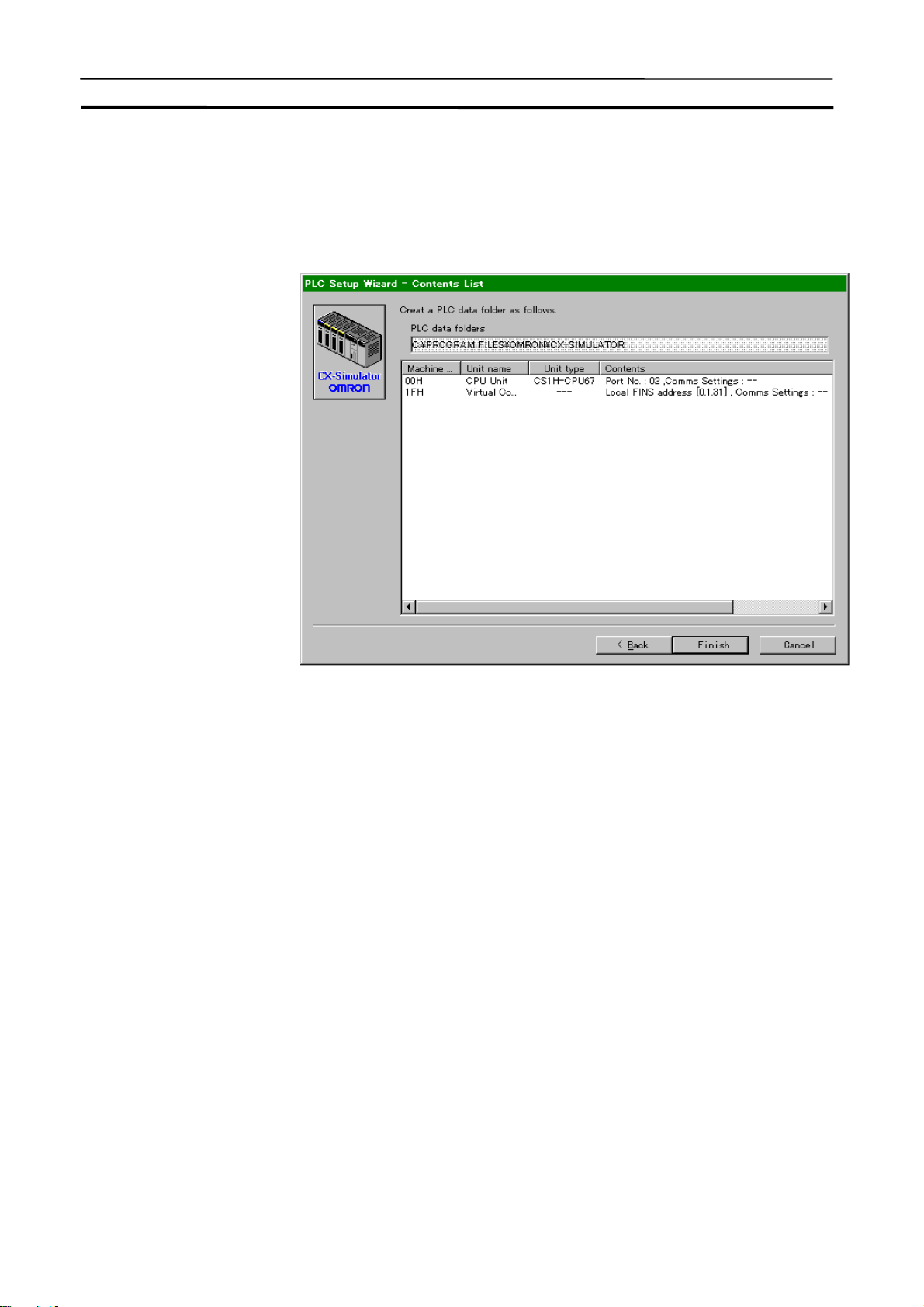
Creating a New PLC Section 3-5
13. Exit the Serial communications window
Repeat the operation from 10 to 12 as required. After completing all settings,
click [Next(N)>] button to display the [Contents List] window.
• Contents
14. Pressing the [Complete] button after confirming the contents of the [PLC
Setup] wizard will exit the [PLC Setup] wizard. Then the Ladder Engine is
started and each window for Work CX-Simulator, CX-Simulator Debug
Console, and Status will be displayed.
• The Work CX-Simulator window The Ladder Engine of the Simulator
will be connected to the
CX-Programmer.
• The CX-Simulator Debug Console
window
Execute operation for the Ladder
Engine.
• The Status window Display the status of the Ladder En-
gine and set for the Ladder Engine.
Refer to the following items for the contents of each window.
• Work CX-Simulator window 3-8 Connecting to the
CX-Programmer Version 2.1 or Lower
• The CX-Simulator Debug Console
window
• The Status window 3-6 Each Part of the Windows
3-6 Each Part of the Windows
54
Page 94

Creating a New PLC Section 3-5
Note
15. Clicking the [Connect] button in the [Work CX-Simulator] window will dis-
play the network set to CX-Programmer and its FINS address in the [Guide
to Connect]. Set for the CX-programmer as guided.
The details of [Work CX-Simulator] setting will be explained in 3-8 Connecting
to the CX-Programmer.
3-5-2 Open Existing PLC
The Setting information of PLC previously created is saved in the PLC data
folder. Opening the existing PLC enables to use the same setting any times.
1,2,3…
1. Selecting [Select PLC] in the PLC Setup wizard or in the [Settings] of System Status Setting when starting the CX-Simulator will display the [Select
PLC] dialog box.
Note
2. Select [Open an existing PLC] and specify the folder.
• Recently-used PLC data folders are selected from the list.
• Also possible to set by browsing folders with Browse button.
3. Click the [OK] button to exit the [Select PLC] dialog box. The Ladder Engine is started with the contents set before and each window for Work
CX-Simulator, CX-Simulator Debug Console, and Status is displayed.
4. Clicking the [Connect] button in the [Work CX-Simulator] window will display the network and its FINS address set to the CX-Programmer in the
[Guide to Connect]. Set to the CX-Programmer guided by the display.
The details of [Work CX-Simulator] setting will be explained in 3-8 Connecting
to the CX-Programmer.
55
Page 95

Creating a New PLC Section 3-5
A
A
Note
When creating a new PLC or opening an existing PLC, the settings so far will
be discarded. Save the data before these operations if the settings so far or the
program downloaded to the Ladder Engine are needed.
3-5-3 Folder Used in CX-Simulator
The CX-Simulator creates folders for data used by each PLC created (PLC
data folder). The PLC data folders contain setting information peculiar to the
created PLC and file memories able to be accessed by the PLC. Contents of
the PLC data folder are as follows:
PLC Data folder
PLC model setting file (PLC.ini)
Break condition setting file (*.bsf)
Command log setting file (*.csf)
utomatic setting file (Autoexec.dbg)
Save-all file
PLC file memory <CARD>
UTOEXEC file
User-specified file
User-specified folder
User-specified file
EM file memory <EM>
User-specified file
User-specified folder
User-specified file
Log folder <LOG>
Command log file (*.flg)
Data trace data file (*.cdt)
Data replay file (*.csv)
shows a folder.
< > shows a proper folder name.
56
Page 96

Creating a New PLC Section 3-5
PLC data folder
Contain data files peculiar to each PLC used by the CX-Simulator. The following files are contained as data files.
File Type Extension Contents
PLC Model Setting File ini PLC model and registered unit setting file
Break Condition Setting File bsf I/O break condition setting data file
Command Log Setting File csf Command log setting data file
Automatic Setting File File created when exiting the system
Debugger Setting File dbg Debugger automatic setting file
(AUTOEXEC.DBG)
I/O Memory File dat Automatic setting file for I/O memory con-
sisting of multiple files (Memoryn
underlined part is a serial number)
Save-all File File created on the [Save all] of the [File]
menu in the [Debug Console] window.
Debugger Setting File dbg Debugger setting file
I/O Memory File dat I/O memory save file
.dat: the
Note
A total size of the I/O Memory Files is about 10 MB.
The folder for the file memory
The folder for the file memory corresponds to CS/CJ/CP-series CPU Unit file
memory function, which is fixedly allocated for each file system.
Name Root Folder Name Note
PLC file memory
(Memory card)
EM file memory EM Capacity limit following the PLC Setting
The file created as the file memory is compatible with the one for
CS/CJ/CP-series CPU Unit. The operation to the folder for the file memory can
be performed in the same way as the file memory for CS/CJ/CP-series CPU
Unit.
Note
1. If the hard disk capacity of the computer is smaller than that of the file
memory, file write may fail.
2. Refer to Section 5 File Memory Functions of CS/CJ Series Programming
Manual for the details on the file memory functions.
CARD No limited capacity (following the capacity
of the computer hard disk)
Log folder
The test data for the CX-Simulator is stored. The following data files for each
use are available.
File type Extension Content
Command Log File flg The data file storing CX-Programmer's
operation log
Data Trace File cdt The compatible data file with the
CX-Programmer's data trace file
Data Replay File csv CSV-format text file
Note
Refer to 8-3 Generating Virtual External Inputs for the data file in the log folder.
57
Page 97

Each Part of the Windows Section 3-6
3-6 Each Part of the Windows
This section explains each part of the windows in the CX-Simulator.
3-6-1 Basic Windows Arrangement
Work CX-Simulator
(for connecting
CX-Programmer)
System Status
Setting (for
status display)
CX-Simulator Debug Console
(for running)
The basic operation of the CX-Simulator is performed in the [CX-Simulator
Debug Console] window and the [System Status Setting] window. The
[CX-Simulator Debug Console] window executes operation for the Ladder
Engine. The [System Status Setting] window displays the status of the Ladder
Engine and sets for the Ladder Engine.
Note: Only the [Debug Console] window will be displayed when the CX-Simulator is
started from the CX-Programmer.
58
Page 98

Each Part of the Windows Section 3-6
g
g
3-6-2 Basic Windows Transition
The following shows the basic windows transition of the CX-Simulator. There
are two transitions: One from the [CX-Simulator Debug Console] window and
the other from the [System Status Setting] window.
Transition of System Status Setting
Window
System Status Setting
(Outline display mode)
(Detail display mode)
Setting
Transition of Debug Console Window
CX-Simulator Debug Console
Step run display
Task control
PLC selection
PLC setting wizard
PLC unit registration
Network communications
settin
Network communications registration
Serial communications
setting
Serial port setting
Time-related PLC operation settin
PLC operation setting
UM setting
Messages
I/O break condition
I/O break condition
registration
File operation menu
Connect to Simulator
Console display setting
Data regeneration menu
PLC operation setting
I/O Condition Tool startup
Data Replay Tool startup
Command log setting
Alarm
59
Page 99

System Status Setting Window Section 3-7
g
3-7 System Status Setting Window
3-7-1 System Status Setting Window
The [System Status Setting] window performs PLC model selection, the
Ladder Engine status display, cycle time display, UM set/display, network
communications set, Serial communications set, and others.
Transition of System Status Setting
Window
System Status Setting
(Outline display mode)
(Detail display mode)
Setting
PLC selection
PLC setting wizard
PLC unit registration
Network communications
setting
Network communications registration
Serial communications
setting
Serial port setting
Time-related PLC operation settin
PLC operation setting
UM setting
Messages
Alarm
60
Page 100

System Status Setting Window Section 3-7
y
A
Names and Functions
PLC model
Status display LED
Cycle time display
Operation mode
UM settings display
Setting menu displa
Message display button
button
larm display button
Outline/detail status
display button
Name Function
PLC Model Display the PLC /CPU model currently set.
Status Display LED Display operation status of the Ladder Engine.
Cycle time Display Display the cycle time mode of the Ladder Engine
Operation Mode Display the operation mode (RUN, MONITOR, or
UM Settings Display Display the UM area able to be accessed by the Ladder
Setting Menu Display
button
Message Display
button
Alarm Display button Start the Alarm Display application.
Outline/Detail Status
Display button
(Estimated/Simulated cycle time) and the up-to-date
cycle time (Unit: ms).
PROGRAM) of the Ladder Engine
Engine and the object name.
Display the setting menu.
Display the Message Display window.
Switch the display mode of the System Status Setting
window (Outline or Detail).
61
 Loading...