

Page 1

Cat. No. W344-E1-11
SYSMAC
WS02-PSTC1-E
CX-Protocol Ver. 1.9
OPERATION MANUAL
Page 2

Page 3

SYSMAC WS02-PSTC1-E CX-Protocol Ver. 1.9
Operation Manual
Revised December 2009
Page 4

iv
Page 5

Notice:
OMRON products are manufactured for use according to proper procedures by a qualified operator
and only for the purposes described in this manual.
The following conventions are used to indicate and classify precautions in this manual. Always heed
the information provided with them. Failure to heed precautions can result in injury to people or damage to the product.
!DANGER Indicates information that, if not heeded, is likely to result in loss of life or serious injury.
Additionally, there may be severe property damage.
!WARNING Indicates information that, if not heeded, could possibly result in loss of life or serious
injury. Additionally, there may be severe property damage.
!Caution Indicates information that, if not heeded, could result in relatively serious or minor injury,
damage to the product, or faulty operation.
OMRON Product References
All OMRON products are capitalized in this manual. The word “Unit” is also capitalized when it refers to
an OMRON product, regardless of whether or not it appears in the proper name of the product.
The abbreviation “Ch,” which appears in some displays and on some OMRON products, often means
“word” and is abbreviated “Wd” in documentation in this sense.
The abbreviation “PLC” means Programmable Controller and the abbreviation “PC” means personal
computer and are not used as abbreviations for anything else.
The abbreviation “PMSU” means Protocol Macro Support Unit and refers to the Communications
Board for the C200HX/HG/HE, Serial Communications Board for the CS, and Serial Communications
Units for the CS/CJ.
Visual Aids
The following headings appear in the left column of the manual to help you locate different types of
information.
OMRON, 2008
All rights reserved. No part of this publication may be reproduced, stored in a retrieval system, or transmitted, in any form,
or by any means, mechanical, electronic, photocopying, recording, or otherwise, without the prior written permission
of OMRON.
No patent liability is assumed with respect to the use of the information contained herein. Moreover, because OMRON is
constantly striving to improve its high-quality products, the information contained in this manual is subject to change without
notice. Every precaution has been taken in the preparation of this manual. Nevertheless, OMRON assumes no responsibility
for errors or omissions. Neither is any liability assumed for damages resulting from the use of the information contained
in this publication.
Note Indicates information of particular interest for efficient and convenient opera-
tion of the product.
1,2,3... 1. Indicates lists of one sort or another, such as procedures, checklists, etc.
v
Page 6

vi
Page 7

TABLE OF CONTENTS
PRECAUTIONS . . . . . . . . . . . . . . . . . . . . . . . . . . . . . . . . xxiii
1 Intended Audience . . . . . . . . . . . . . . . . . . . . . . . . . . . . . . . . . . . . . . . . . . . . . . . . . xxiv
2 General Precautions . . . . . . . . . . . . . . . . . . . . . . . . . . . . . . . . . . . . . . . . . . . . . . . . xxiv
3 Safety Precautions. . . . . . . . . . . . . . . . . . . . . . . . . . . . . . . . . . . . . . . . . . . . . . . . . . xxiv
4 Operating Environment Precautions . . . . . . . . . . . . . . . . . . . . . . . . . . . . . . . . . . . . xxiv
5 Application Precautions . . . . . . . . . . . . . . . . . . . . . . . . . . . . . . . . . . . . . . . . . . . . . xxv
6 Software Operating Procedures. . . . . . . . . . . . . . . . . . . . . . . . . . . . . . . . . . . . . . . . xxvi
SECTION 1
Introduction. . . . . . . . . . . . . . . . . . . . . . . . . . . . . . . . . . . . 1
1-1 Overview of the CX-Protocol . . . . . . . . . . . . . . . . . . . . . . . . . . . . . . . . . . . . . . . . . 2
1-2 Features . . . . . . . . . . . . . . . . . . . . . . . . . . . . . . . . . . . . . . . . . . . . . . . . . . . . . . . . . . 2
1-3 Checking the Contents of the Package . . . . . . . . . . . . . . . . . . . . . . . . . . . . . . . . . . 5
1-4 Supported PLC Models and Personal Computers . . . . . . . . . . . . . . . . . . . . . . . . . . 5
1-5 System Configuration . . . . . . . . . . . . . . . . . . . . . . . . . . . . . . . . . . . . . . . . . . . . . . . 9
1-6 Protocol Macro . . . . . . . . . . . . . . . . . . . . . . . . . . . . . . . . . . . . . . . . . . . . . . . . . . . . 13
1-7 Protocol Macro Structure . . . . . . . . . . . . . . . . . . . . . . . . . . . . . . . . . . . . . . . . . . . . 16
1-8 Data Created by the CX-Protocol . . . . . . . . . . . . . . . . . . . . . . . . . . . . . . . . . . . . . . 19
1-9 Main Screens of the CX-Protocol . . . . . . . . . . . . . . . . . . . . . . . . . . . . . . . . . . . . . . 20
1-10 Overview of Project Creation . . . . . . . . . . . . . . . . . . . . . . . . . . . . . . . . . . . . . . . . . 23
1-11 Incorporated Standard System Protocol . . . . . . . . . . . . . . . . . . . . . . . . . . . . . . . . . 24
1-12 Basic Procedure of the Protocol Macro Usage . . . . . . . . . . . . . . . . . . . . . . . . . . . . 25
1-13 Specifications . . . . . . . . . . . . . . . . . . . . . . . . . . . . . . . . . . . . . . . . . . . . . . . . . . . . . 32
1-14 Differences between Protocol Macros . . . . . . . . . . . . . . . . . . . . . . . . . . . . . . . . . . 36
SECTION 2
Installing/Uninstalling/Starting/Ending . . . . . . . . . . . . . 39
2-1 Connecting to a PLC . . . . . . . . . . . . . . . . . . . . . . . . . . . . . . . . . . . . . . . . . . . . . . . . 40
2-2 Installing and Uninstalling the Software. . . . . . . . . . . . . . . . . . . . . . . . . . . . . . . . . 42
2-3 Uninstalling Software . . . . . . . . . . . . . . . . . . . . . . . . . . . . . . . . . . . . . . . . . . . . . . . 49
2-4 Startup . . . . . . . . . . . . . . . . . . . . . . . . . . . . . . . . . . . . . . . . . . . . . . . . . . . . . . . . . . . 52
2-5 Shutdown. . . . . . . . . . . . . . . . . . . . . . . . . . . . . . . . . . . . . . . . . . . . . . . . . . . . . . . . . 53
2-6 Outline of User Interface. . . . . . . . . . . . . . . . . . . . . . . . . . . . . . . . . . . . . . . . . . . . . 54
SECTION 3
Protocol Macro . . . . . . . . . . . . . . . . . . . . . . . . . . . . . . . . . 65
3-1 Protocol Macro Outline. . . . . . . . . . . . . . . . . . . . . . . . . . . . . . . . . . . . . . . . . . . . . . 66
3-2 Sequence Attributes (Common to All Steps) . . . . . . . . . . . . . . . . . . . . . . . . . . . . . 83
3-3 Step Attributes. . . . . . . . . . . . . . . . . . . . . . . . . . . . . . . . . . . . . . . . . . . . . . . . . . . . . 92
3-4 Communication Message Attributes. . . . . . . . . . . . . . . . . . . . . . . . . . . . . . . . . . . . 103
3-5 Creating Matrices . . . . . . . . . . . . . . . . . . . . . . . . . . . . . . . . . . . . . . . . . . . . . . . . . . 120
3-6 Examples of Standard System Protocols . . . . . . . . . . . . . . . . . . . . . . . . . . . . . . . . 124
3-7 Example of Communications Sequence . . . . . . . . . . . . . . . . . . . . . . . . . . . . . . . . . 126
3-8 Executing a Created Communications Sequence (CS/CJ) . . . . . . . . . . . . . . . . . . . 129
3-9 Executing a Created Communications Sequence (C200HX/HG/HE) . . . . . . . . . . 136
3-10 Auxiliary Area and Allocated Data Areas . . . . . . . . . . . . . . . . . . . . . . . . . . . . . . . 142
vii
Page 8

TABLE OF CONTENTS
SECTION 4
Using the Protocol Macro Function. . . . . . . . . . . . . . . . . 159
4-1 Applicable Range of the Protocol Macro Function . . . . . . . . . . . . . . . . . . . . . . . . 160
4-2 Protocol Creation Process . . . . . . . . . . . . . . . . . . . . . . . . . . . . . . . . . . . . . . . . . . . 162
4-3 Transmission Control Mode Setup . . . . . . . . . . . . . . . . . . . . . . . . . . . . . . . . . . . . 165
4-4 Ladder Programming Method . . . . . . . . . . . . . . . . . . . . . . . . . . . . . . . . . . . . . . . . 168
4-5 Calculation Method of Monitoring Time. . . . . . . . . . . . . . . . . . . . . . . . . . . . . . . . 179
4-6 Operation Confirmation. . . . . . . . . . . . . . . . . . . . . . . . . . . . . . . . . . . . . . . . . . . . . 181
4-7 Errors at the Protocol Execution . . . . . . . . . . . . . . . . . . . . . . . . . . . . . . . . . . . . . . 183
4-8 Communications Response Time Performance. . . . . . . . . . . . . . . . . . . . . . . . . . . 192
4-9 Cycle Time Performance . . . . . . . . . . . . . . . . . . . . . . . . . . . . . . . . . . . . . . . . . . . . 209
SECTION 5
Object Creation . . . . . . . . . . . . . . . . . . . . . . . . . . . . . . . . . 211
5-1 Creating Projects and Protocols. . . . . . . . . . . . . . . . . . . . . . . . . . . . . . . . . . . . . . . 212
5-2 Creating Sequences and Steps . . . . . . . . . . . . . . . . . . . . . . . . . . . . . . . . . . . . . . . . 216
5-3 Creating Messages and Matrices . . . . . . . . . . . . . . . . . . . . . . . . . . . . . . . . . . . . . . 217
5-4 System Protocol Display and Editing . . . . . . . . . . . . . . . . . . . . . . . . . . . . . . . . . . 219
SECTION 6
Project and Protocol Editing . . . . . . . . . . . . . . . . . . . . . . 221
6-1 Editing Projects . . . . . . . . . . . . . . . . . . . . . . . . . . . . . . . . . . . . . . . . . . . . . . . . . . . 222
6-2 Editing Protocols . . . . . . . . . . . . . . . . . . . . . . . . . . . . . . . . . . . . . . . . . . . . . . . . . . 224
SECTION 7
Sequence Setting and Editing. . . . . . . . . . . . . . . . . . . . . . 227
7-1 Setting Sequences . . . . . . . . . . . . . . . . . . . . . . . . . . . . . . . . . . . . . . . . . . . . . . . . . 228
7-2 Editing Sequences . . . . . . . . . . . . . . . . . . . . . . . . . . . . . . . . . . . . . . . . . . . . . . . . . 234
SECTION 8
Step Setting and Editing . . . . . . . . . . . . . . . . . . . . . . . . . . 237
8-1 Step Setting . . . . . . . . . . . . . . . . . . . . . . . . . . . . . . . . . . . . . . . . . . . . . . . . . . . . . . 238
8-2 Step Editing . . . . . . . . . . . . . . . . . . . . . . . . . . . . . . . . . . . . . . . . . . . . . . . . . . . . . . 244
SECTION 9
Setting and Editing Messages and Matrix Lists . . . . . . . 247
9-1 Creating Messages. . . . . . . . . . . . . . . . . . . . . . . . . . . . . . . . . . . . . . . . . . . . . . . . . 248
9-2 Matrix Creation . . . . . . . . . . . . . . . . . . . . . . . . . . . . . . . . . . . . . . . . . . . . . . . . . . . 262
9-3 Message and Matrix Editing . . . . . . . . . . . . . . . . . . . . . . . . . . . . . . . . . . . . . . . . . 263
SECTION 10
Communications PLC Setup and Online Connections . 267
10-1 PLC System Configuration . . . . . . . . . . . . . . . . . . . . . . . . . . . . . . . . . . . . . . . . . . 268
10-2 Communications Settings between Personal Computer and PLC . . . . . . . . . . . . . 269
10-3 Online Connections and Mode Changes . . . . . . . . . . . . . . . . . . . . . . . . . . . . . . . . 276
10-4 Modem Connections . . . . . . . . . . . . . . . . . . . . . . . . . . . . . . . . . . . . . . . . . . . . . . . 278
10-5 I/O Table Creation . . . . . . . . . . . . . . . . . . . . . . . . . . . . . . . . . . . . . . . . . . . . . . . . . 287
10-6 PMSU Communications Port Settings . . . . . . . . . . . . . . . . . . . . . . . . . . . . . . . . . 288
10-7 Transfer of Communications Port Setting Data to PLC . . . . . . . . . . . . . . . . . . . . 290
viii
Page 9

TABLE OF CONTENTS
SECTION 11
Protocol Data Transferring and Printing . . . . . . . . . . . . 293
11-1 Transferring and Reading Protocol Data between the Computer and PMSU . . . . 294
11-2 Printing Protocols . . . . . . . . . . . . . . . . . . . . . . . . . . . . . . . . . . . . . . . . . . . . . . . . . . 299
11-3 Importing Protocol Data from PST/PSS Files . . . . . . . . . . . . . . . . . . . . . . . . . . . . 301
11-4 CS/CJ Protocol and C200HX/HG/HE Protocol . . . . . . . . . . . . . . . . . . . . . . . . . . . 303
SECTION 12
Tracing and Monitoring . . . . . . . . . . . . . . . . . . . . . . . . . . 305
12-1 Tracing Transmission Lines . . . . . . . . . . . . . . . . . . . . . . . . . . . . . . . . . . . . . . . . . . 306
12-2 Outline of PLC Memory Window. . . . . . . . . . . . . . . . . . . . . . . . . . . . . . . . . . . . . . 310
12-3 I/O Memory Display and Editing . . . . . . . . . . . . . . . . . . . . . . . . . . . . . . . . . . . . . . 317
12-4 I/O Memory Monitor . . . . . . . . . . . . . . . . . . . . . . . . . . . . . . . . . . . . . . . . . . . . . . . 320
12-5 I/O Memory Transfer and Comparison. . . . . . . . . . . . . . . . . . . . . . . . . . . . . . . . . . 325
SECTION 13
Error and Error Log Display. . . . . . . . . . . . . . . . . . . . . . 329
SECTION 14
Troubleshooting . . . . . . . . . . . . . . . . . . . . . . . . . . . . . . . . 337
SECTION 15
Help . . . . . . . . . . . . . . . . . . . . . . . . . . . . . . . . . . . . . . . . . . 345
Appendices
A Creating the Protocol Applications . . . . . . . . . . . . . . . . . . . . . . . . . . . . . . . . . . . . 349
B PLC Setup and PMSU Settings . . . . . . . . . . . . . . . . . . . . . . . . . . . . . . . . . . . . . . . 363
C Wiring RS-232C Cable Connectors . . . . . . . . . . . . . . . . . . . . . . . . . . . . . . . . . . . . 369
Revision History . . . . . . . . . . . . . . . . . . . . . . . . . . . . . . . . 373
ix
Page 10

TABLE OF CONTENTS
x
Page 11

About this Manual:
The CX-Protocol is Support Software for the protocol macro functionality of Windows 95, Windows 98,
Windows 98SE, Windows Me, Windows NT (SP6a), Windows 2000 (SP2 or higher), Windows XP, and
Windows Vista. This manual describes the installation and operation of the CX-Protocol and includes
the sections described below.
This manual is intended for the following personnel:
Personnel in charge of installing FA devices
Personnel designing FA systems
Personnel managing FA facilities
Name Cat. No. Contents
SYSMAC WS02-PSTC1-E
CX-Protocol
Operation Manual
CX-One Setup Manual
CXONE-AL@@C-V4/AL@@D-V4
SYSMAC CS/CJ Series
CS1W-SCB@1-V1, CS1W-SCU@1-V1
CJ1W-SCU@1-V1, CJ1W-SCU@2
Serial Communications Boards and Serial
Communications Unit Operation Manual
SYSMAC CS/CJ/CP/NSJ Series
CS1G/H-CPU@@H
CS1G/H-CPU@@-EV1
CS1D-CPU@@H
CS1D-CPU@@S
CS1W-SCU@@-V1
CS1W-SCB@@-V1
CJ2H-CPU6@-EIP
CJ2H-CPU6@
CJ1H-CPU@@H-R
CJ1G/H-CPU@@H
CJ1G-CPU@@P
CJ1G-CPU@@
CJ1M-CPU@@
CJ1W-SCU@@-V1
CP1H-X@@@@-@
CP1H-XA@@@@-@
CP1H-Y@@@@-@
NSJ@-@@@@(B)-G5D
NSJ@-@@@@(B)-M3D
Communications Commands Reference
Manual
SYSMAC CJ Series
CJ2H-CPU6@-EIP
CJ2H-CPU6@
Programmable Controllers
Hardware User's Manual
SYSMAC CJ Series
CJ2H-CPU6@-EIP
CJ2H-CPU6@
Programmable Controllers
Software User's Manual
SYSMAC CS Series
CS1G/H-CPU@@H
CS1G/H-CPU@@-EV1
Programmable Controllers
Operation Manual
W344
(this manual)
W463 Installation and overview of CX-One FA Integrated Tool Pack-
W336 Describes the use of Serial Communications Unit and Boards to
W342 Describes the C-series (Host Link) and FINS communications
W472 Provides an outline of and describes the design, installation,
W473 Describes programming and other methods to use the functions
W339 Describes the installation and operation of the CS-series PLCs.
Describes the use of the CX-Protocol to create protocol macros
as communications sequences to communicate with external
devices. (This manual)
age.
perform serial communications with external devices, including
the usage of standard system protocols for OMRON products.
commands used with CS/CJ/CP-series PLCs and NSJ-series
Controllers.
maintenance, and other basic operations for the CJ-series CJ2
CPU Units.
The following information is included:
Overview and features
System configuration
Installation and wiring
Troubleshooting
Use this manual together with the W473.
of the CJ2 CPU Units.
The following information is included:
CPU Unit operation
Internal memory areas
Programming
Ta s ks
CPU Unit built-in functions
Use this manual together with the W472.
xi
Page 12

Name Cat. No. Contents
SYSMAC CJ Series
CJ1H-CPU@@H-R, CJ1G/H-CPU@@H,
CJ1G-CPU@@P,
CJ1G-CPU@@, CJ1M-CPU@@
Programmable Controllers
Operation Manual
SYSMAC CS/CJ/NSJ Series
CS1G/H-CPU@@H, CS1G/H-CPU@@EV1, CS1D-CPU@@H, CS1D-CPU@@S,
CJ1H-CPU@@H-R, CJ1G/H-CPU@@H,
CJ1G-CPU@@P, C J 1 G- C P U @@, CJ1MCPU@@, NSJ@-@@@@(B)-G5D
NSJ@-@@@@(B)-M3D
Programmable Controllers
Programming Manual
SYSMAC CS/CJ Series
CS1G/H-CPU@@-EV1,
CS1G/H-CPU@@H,
CS1D-CPU@@H, CS1D-CPU@@S,
CJ2H-CPU6@-EIP, CJ2H-CPU6@,
CJ1H-CPU@@H-R
CJ1G-CPU@@, CJ1G/H-CPU@@H,
CJ1G-CPU@@P, C J 1 M- C P U @@
SYSMAC One NSJ Series
NSJ@-@@@@(B)-G5D
NSJ@-@@@@(B)-M3D
Programmable Controllers
Instructions Reference Manual
SYSMAC CP Series
CP1H-X@@@@-@
CP1H-XA@@@@-@
CP1H-Y@@@@-@
CP1H CPU Unit Operation Manual
NSJ Series
NSJ5-TQ@@(B)-G5D, NSJ5-SQ@@(B)-
G5D, NSJ8-TV@@(B)-G5D, NSJ10TV@@(B)-G5D, NSJ12-TS@@(B)-G5D,
NSJ5-TQ@@(B)-M3D, NSJ5-SQ@@(B)M3D, NSJ8-TV@@(B)-M3D, NSJWETN21, NSJW-CLK21-V1, NSJW-IC101
Operation Manual
SYSMAC WS02-CXPC1-V9
CX-Programmer
Operation Manual
SYSMAC CS/CJ Series
CQM1H-PRO-E1
C200H-PRO27-E, CQM1-PRO01-E
Programming Consoles
Operation Manual
W393 Describes the installation and operation of the CJ-series PLCs.
W394 Describes programming and other methods to use the functions
W474 Describes the ladder diagram programming instructions sup-
W450 Provides the following information on the CP Series:
W452 Provides the following information about the NSJ-series NSJ
W446 Provides information on how to use the CX-Programmer, a pro-
W341 Provides information on how to program and operate
of the CS/CJ/NSJ-series PLCs.
The following information is included:
• Programming
•Tasks
• File memory
• Other functions
Use this manual in combination with the SYSMAC CS Series
Operation Manual (W339) or SYSMAC CJ Series Operation
Manual (W393).
ported by CS/CJ-series or NSJ-series PLCs.
When programming, use this manual together with the Opera-
tion Manual or Hardware User's Manual (CS1: W339, CJ1:
W393,or CJ2:W472) and Programming Manual or Software
User's Manual (CS1/CJ1:W394 or CJ2:W473).
• Overview/Features
• System configuration
• Mounting and wiring
• I/O memory allocation
• Troubleshooting
Use this manual together with the CP1H Programmable Control-
lers Programming Manual (W451).
Controllers:
Overview and features
Designing the system configuration
Installation and wiring
I/O memory allocations
Troubleshooting and maintenance
Use this manual in combination with the following manuals:
SYSMAC CS Series Operation Manual (W339), SYSMAC CJ
Series Operation Manual (W393), SYSMAC CS/CJ Series Programming Manual (W394), and NS-V1/-V2 Series Setup Manual
(V083)
gramming device that supports the CS/CJ-series PLCs, and the
CX-Net contained within CX-Programmer.
CS/CJ-series PLCs using a Programming Console.
!WARNING Failure to read and understand the information provided in this manual may result in per-
sonal injury or death, damage to the product, or product failure. Please read each section
in its entirety and be sure you understand the information provided in the section and
related sections before attempting any of the procedures or operations given.
xii
Page 13

Please read this manual carefully and be sure you understand the information provided before
attempting to install and/or operate the CX-Protocol. Be sure to read the precautions provided in
the following section.
Section 1 Introduction outlines the Protocol Macro function and the CX-Protocol.
Section 2 Environment/Installing/Uninstalling/Starting/Editing outlines the functions of CX-Proto-
col and describes the operating environment, installation procedure, and the setting of the usage environment.
Section 3 Protocol Macro describes details of the protocol macro functions.
Section 4 Using the Protocol Macro Function describes various precautions in using the protocol
macro function.
Section 5 Object Creation describes how to create objects, such as projects, protocols, sequences,
steps, messages, and matrices.
Section 6 Project and Protocol Editing describes details of the editing of projects and protocols.
Section 7 Sequence Setting and Editing describes details of the setting and editing of sequences.
Section 8 Step Setting and Editing describes details of the setting and editing of steps.
Section 9 Setting and Editing Messages and Matrix Lists describes details of the setting and edit-
ing of messages and matrix lists.
Section 10 Communications PLC Setup and Online Connections describes details of the communications settings and online connections.
Section 11 Protocol Data Transferring and Printing describes details of the transferring, converting,
and printing of protocol data.
Section 12 Tracing and Monitoring describes details of PLC memory area monitoring and the transmission line tracing.
Section 13 Error and Error Log Display describes details of the displaying of errors and the error
log.
Section 14 Troubleshooting lists the error messages and describes their causes and remedies.
Section 15 Help describes the online help services.
Appendix A Creating the Protocol Applications shows some examples of data transmission
between personal computers using the protocol macro function.
Appendix B PLC Setup and PMSU Settings provides the settings for the PLC Setup and PMSU.
Appendix C Wiring RS-232C Cable Connectors describes how to wire RS-232C connectors.
xiii
Page 14

The CS Series, CJ Series, NSJ Series, and CP Series are subdivided as shown below.
CS Series
CS1-H CPU Units
CS1H-CPU@@H
CS1G-CPU@@H
CS1 CPU Units
CS1H-CPU@@(-V1)
CS1G-CPU@@(-V1)
CS1D CPU Units
CS1D CPU Units for
Duplex Systems
CS1D-CPU@@H
CS1D CPU Units for
Simplex Systems
CS1D-CPU@@S
CS1D Process-control CPU Units
CS1D-CPU@@P
CS-series Basic I/O Units
CS-series Special I/O Units
CS-series CPU Bus Units
CS-series Power Supply Units
Note: A special Power Supply Unit must
be used for CS1D CPU Units.
CJ Series
CJ2 CPU Units
CJ2H CPU Units
CJ2H-CPU6@-EIP
CJ2H-CPU6@
CJ1 CPU Units
CJ1-H CPU Units
CJ1H-CPU@@H-R
CJ1H-CPU@@H
CJ1G-CPU@@H
CJ1G -CPU@@P
(Loop-control CPU Units)
CJ1M CPU Units
CJ1M-CPU@@
CJ1 CPU Units
CJ1G-CPU@@
CJ-series Basic I/O Units
CJ-series Special I/O Units
CJ-series CPU Bus Units
CJ-series Power Supply Units
CS/CJ/NSJ/CP Series
NSJ-series Expansion Units
NSJ Series
NSJ Controllers
NSJ5-TQ@@(B)-G5D
NSJ5-SQ@@(B)-G5D
NSJ8-TV@@(B)-G5D
NSJ10-TV@@(B)-G5D
NSJ12-TS@@(B)-G5D
NSJ Controllers
NSJ5-TQ@@(B)-M3D
NSJ5-SQ@@(B)-M3D
NSJ8-TV@@(B)-M3D
CP Series
CP1H CPU Units
CP1H-X@@@@-@
CP1H-XA@@@@-@
CP1H-Y@@@@-@
CPM1A-series Expansion I/O Units
CPM1A-series Expansion Units
CJ-series Special I/O Units
CJ-series CPU Bus Units
xiv
Page 15

Read and Understand this Manual
Please read and understand this manual before using the product. Please consult your OMRON
representative if you have any questions or comments.
Warranty and Limitations of Liability
WARRANTY
(1) The warranty period for the Software is one year from either the date of purchase or the date on which
the Software is delivered to the specified location.
(2) If the User discovers a defect in the Software (i.e., substantial non-conformity with the manual), and
returns it to OMRON within the above warranty period, OMRON will replace the Software without charge
by offering media or downloading services from the Internet. And if the User discovers a defect in the
media which is attributable to OMRON and returns the Software to OMRON within the above warranty
period, OMRON will replace the defective media without charge. If OMRON is unable to replace the
defective media or correct the Software, the liability of OMRON and the User's remedy shall be limited to
a refund of the license fee paid to OMRON for the Software.
LIMITATIONS OF LIABILITY
(1) THE ABOVE WARRANTY SHALL CONSTITUTE THE USER'S SOLE AND EXCLUSIVE REMEDIES
AGAINST OMRON AND THERE ARE NO OTHER WARRANTIES, EXPRESSED OR IMPLIED,
INCLUDING BUT NOT LIMITED TO, WARRANTY OF MERCHANTABILITY OR FITNESS FOR A
PARTICULAR PURPOSE. IN NO EVENT WILL OMRON BE LIABLE FOR ANY LOST PROFITS OR
OTHER INDIRECT, INCIDENTAL, SPECIAL, OR CONSEQUENTIAL DAMAGES ARISING OUT OF
USE OF THE SOFTWARE.
(2) OMRON SHALL ASSUME NO LIABILITY FOR DEFECTS IN THE SOFTWARE BASED ON
MODIFICATION OR ALTERATION OF THE SOFTWARE BY THE USER OR ANY THIRD PARTY.
(3) OMRON SHALL ASSUME NO LIABILITY FOR SOFTWARE DEVELOPED BY THE USER OR ANY
THIRD PARTY BASED ON THE SOFTWARE OR ANY CONSEQUENCE THEREOF.
xv
Page 16

Application Considerations
SUITABILITY FOR USE
THE USER SHALL NOT USE THE SOFTWARE FOR A PURPOSE THAT IS NOT DESCRIBED IN THE
ATTACHED USER MANUAL.
xvi
Page 17

Disclaimers
CHANGE IN SPECIFICATIONS
The software specifications and accessories may be changed at any time based on improvements or for
other reasons.
EXTENT OF SERVICE
The license fee of the Software does not include service costs, such as dispatching technical staff.
ERRORS AND OMISSIONS
The information in this manual has been carefully checked and is believed to be accurate; however, no
responsibility is assumed for clerical, typographical, or proofreading errors, or omissions.
xvii
Page 18

Version Upgrades
Improvements from Version 1.9 to Version 1.91
The following functionality has been added in upgrading the CX-Protocol from version 1.9 to 1.91.
Support for Microsoft Windows 7
Note This upgrade accompanies the upgrade of CX-One version 3.2 to CX-One version 4.03.
Improvements from Version 1.81 to Version 1.9
The following functionality has been added in upgrading the CX-Protocol from version 1.81 to 1.9.
New Units Supported
The following Units are now supported.
Series Unit Model
CJ Series Serial Communications Unit CJ1W-SCU22
CJ1W-SCU32
CJ1W-SCU42
Upgraded Functions
The EM Area banks that can be directly specified have been expanded from 0 to C hex to 0 to 18 hex.
!Caution If you attempt to access EM banks 0D to 18 hex from any Unit other than the
CJ1W-SCU22/32/42, a data read/write area exceeded error will occur in the
protocol status. (This will occur even if EM banks 0D to 18 hex are supported
by the CPU Unit.)
Improvements from Version 1.8 to Version 1.81
The following functionality has been added in upgrading the CX-Protocol from version 1.8 to 1.81.
New Units Supported
The following CPU Units are now supported.
Series Models
CJ Series CJ2H-CPU68/67/66/65/64
Improvements from Version 1.71 to Version 1.8
The following functionality has been added in upgrading the CX-Protocol from version 1.71 to 1.8.
New Units Supported
The following CPU Units are now supported.
Series Models
CJ Series CJ2H-CPU68-EIP/67-EIP/66-EIP/65-EIP/64-EIP
Improvements from Version 1.70 to Version 1.71
The following functionality has been added in upgrading the CX-Protocol from version 1.70 to 1.71.
New Units Supported
The following CPU Units are now supported.
Series Models
CJ Series CJ1H-CPU67H-R/66H-R/65H-R/64H-R
xviii
Windows Vista Supported
Page 19

Improvements from Version 1.6 to Version 1.7
The following functionality has been added in upgrading the CX-Protocol from version 1.6 to 1.7.
New Units Supported
The following Serial Communications Units are now supported.
Series Unit Model
CS Series Serial Communications Unit CS1W-SCU31-V1
CJ Series Serial Communications Unit CJ1W-SCU31-V1
The following PLCs are now supported.
Series CPU Units Models
CP Series CP1H-series CPU Units CP1H-XA, CP1H-X, and CP1H-Y
NSJ Series NSJ Controller NSJ@-@@@@(B)-G5D
NSJ@-@@@@(B)-M3D
Protocol Comparisons
• The CX-Protocol can now be used to compare the protocols in the project with those in the PLC.
Improvements from Version 1.5 to Version 1.6
Installing the CX-Protocol from the CX-One FA Integrated Tool Package
Ver. 1.5 Ver. 1.6
The CX-Protocol could be installed only independently.
The CX-Protocol can be installed as one of the functions of the CX-One Integrated Tool Package.
CX-Programmer Startup Method
Ver. 1.5 Ver. 1.6
The CX-Protocol could be started only from the Windows Start Menu.
The CX-Protocol can also be started by right-clicking
one of the following Serial Communications Boards/
Units in the I/O Table Window opened from the CXProgrammer that was installed from the CX-One and
selecting Start Special Application from the pop-up
menu.
• CS1W-SCU@@-V1
• CS1W-SCB@@-V1
• CJ1W-SCU@@-V1
Note When the Start with Settings Inherited Option
is selected, a new project will be created and
the device type setting will be automatically
performed.
xix
Page 20

Version 1.5 Upgrade Information
The changes that have been made from version 1.4 to version 1.5 of the CX-Protocol to support the
upgraded functionality of CS/CJ-series Serial Communications Boards/Units with unit version 1.2 are
explained here.
Version 1.5 Improved Functionality from Version 1.4
Compatible PLCs
Serial Communications Board/Unit Version Upgrade Compatibility
CX-Protocol version 1.5 supports the following CS/CJ-series Serial Communications Boards/Units with
unit version 1.2.
Series Unit Model
CS Series Serial Communications Board CS1W-SCB21-V1, CS1W-SCB41-V1
Serial Communications Unit CS1W-SCU21-V1
CJ Series Serial Communications Unit CJ1W-SCU21-V1, CS1W-SCU41-V1
CX-Protocol version 1.5 supports the following new CPU Units.
Series CPU Unit model
CJ Series CJ1H-CPU67H
Communications Port Settings for Serial Communications Boards/Units
The communications port settings for CS/CJ-series Serial Communications Boards/Units with unit version 1.2 can be set using CX-Protocol version 1.5 in the Communications Port Settings for Boards/
Units. The following Communications Port Settings Dialog Box will be displayed.
xx
For details on each of the settings, refer to the CS/CJ Series Serial Communications Boards and Serial
Communications Units Operation Manual (W336-E1-06 or later).
CX-Protocol version 1.4 or earlier cannot read the CX-Protocol version 1.5 project files (.psw) that contain the communications port settings for the upgrade functions, such as no-protocol and Serial Gateway, in the Serial Communications Boards/Units with unit version 1.2. If an attempt to read these files
is made, the message “Unexpected file format.” will be displayed.
Standard System Protocol Additions
CX-Protocol version 1.5 includes the following additional standard system protocols that have been
added to Serial Communications Boards/Units with unit version 1.2.
• Host Link C-mode Command Master (Sequence numbers 700 to 721)
• Host Link FINS Command Master (Sequence numbers 750 to 767)
• Mitsubishi Computer Link Master (A-compatible, 1C frame, model 1) (Sequence numbers 802 to
817)
Page 21

• Additional communications sequences for CompoWay/F Master (added Sequence numbers 606 to
621)
Operation Manual
The CX-Protocol Ver. 1.4 Operation Manual (W344) is included with CX-Protocol version 1.5. Apart
from the new functions and improvements in version 1.5 explained here, however, there are no other
changes in the upgrade that will affect operation or functionality.
Version 1.4
The following functions have been added to the CX-Protocol with the upgrade from Ver. 1.3 to Ver. 1.4.
New PLCs Supported
Simulation is newly supported for the following PLCs.
Series CPU Unit model numbers
CS CS1D-CPU67H/65H
CS1D-CPU67S/65S/44S/42S
CJ CJ1M-CPU11/21
Version 1.3
The following functions have been added to the CX-Protocol with the upgrade from Ver. 1.2 to Ver. 1.3.
CJ1M-CPU23/22/13/12 CPU Units Supported
Windows XP Supported
Version 1.2
The following functions have been added to the CX-Protocol with the upgrade from Ver. 1.1 to Ver. 1.2.
CS1-H, CJ1, and CJ1-H CPU Units Supported
xxi
Page 22

xxii
Page 23

PRECAUTIONS
This section provides general precautions for using the CX-Protocol and related devices.
The information contained in this section is important for the safe and reliable application of the CX-Protocol. You
must read this section and understand the information contained before attempting to set up or operate the CXProtocol.
1 Intended Audience . . . . . . . . . . . . . . . . . . . . . . . . . . . . . . . . . . . . . . . . . . . . . xxiv
2 General Precautions . . . . . . . . . . . . . . . . . . . . . . . . . . . . . . . . . . . . . . . . . . . . xxiv
3 Safety Precautions. . . . . . . . . . . . . . . . . . . . . . . . . . . . . . . . . . . . . . . . . . . . . . xxiv
4 Operating Environment Precautions . . . . . . . . . . . . . . . . . . . . . . . . . . . . . . . . xxiv
5 Application Precautions . . . . . . . . . . . . . . . . . . . . . . . . . . . . . . . . . . . . . . . . . xxv
6 Software Operating Procedures. . . . . . . . . . . . . . . . . . . . . . . . . . . . . . . . . . . . xxvi
xxiii
Page 24

Intended Audience 1
1 Intended Audience
This manual is intended for the following personnel, who must also have
knowledge of electrical systems (an electrical engineer or the equivalent).
• Personnel in charge of installing FA systems.
• Personnel in charge of designing FA systems.
• Personnel in charge of managing FA systems and facilities.
2 General Precautions
The user must operate the product according to the performance specifications described in the operation manuals.
Before using the product under conditions which are not described in the
manual or applying the product to nuclear control systems, railroad systems,
aviation systems, vehicles, combustion systems, medical equipment, amusement machines, safety equipment, and other systems, machines, and equipment that may have a serious influence on lives and property if used
improperly, consult your OMRON representative.
Make sure that the ratings and performance characteristics of the product are
sufficient for the systems, machines, and equipment, and be sure to provide
the systems, machines, and equipment with double safety mechanisms.
This manual provides information for programming and operating OMRON
PLCs. Be sure to read this manual before attempting to use the software and
keep this manual close at hand for reference during operation.
!WARNING It is extremely important that a PLC and all PLC Units be used for the speci-
fied purpose and under the specified conditions, especially in applications that
can directly or indirectly affect human life. You must consult with your OMRON
representative before applying a PLC System to the above mentioned applications.
3 Safety Precautions
!WARNING Never attempt to disassemble any Units while power is being supplied. Doing
so may result in serious electrical shock or electrocution.
!WARNING Never touch any of the terminals while power is being supplied. Doing so may
result in serious electrical shock or electrocution.
4 Operating Environment Precautions
Do not operate the control system in the following places.
• Where the PLC is exposed to direct sunlight.
• Where the ambient temperature is below 0°C or over 55°C.
• Where the PLC may be affected by condensation due to radical temperature changes.
• Where the ambient humidity is below 10% or over 90%.
• Where there is any corrosive or inflammable gas.
• Where there is excessive dust, saline air, or metal powder.
• Where the PLC is affected by vibration or shock.
• Where water, oil, or chemical may splash onto the PLC.
xxiv
Page 25

Application Precautions 5
!Caution The operating environment of the PLC system can have a large effect on the
longevity and reliability of the system. Improper operating environments can
lead to malfunction, failure, and other unforeseeable problems with the PLC
system. Be sure that the operating environment is within the specified conditions at installation and remains within the specified conditions during the life
of the system.
5 Application Precautions
Observe the following precautions when using the PLC.
!WARNING Failure to abide by the following precautions could lead to serious or possibly
fatal injury. Always heed these precautions.
• Always ground the system to 100 Ω or less when installing the system to
protect against electrical shock.
• Always turn OFF the power supply to the PLC before attempting any of
the following. Performing any of the following with the power supply turned
ON may lead to electrical shock:
• Mounting or removing any Units (e.g., I/O Units, CPU Unit, etc.) or
memory cassettes.
• Assembling any devices or racks.
• Connecting or disconnecting any cables or wiring.
!Caution Failure to abide by the following precautions could lead to faulty operation of
the PLC or system or could damage the PLC or PLC Units. Always heed
these precautions.
• Use the Units only with the power supplies and voltages specified in the
operation manuals. Other power supplies and voltages may damage the
Units.
• Take measures to stabilize the power supply to conform to the rated supply if it is not stable.
• Provide circuit breakers and other safety measures to provide protection
against shorts in external wiring.
• Do not apply voltages exceeding the rated input voltage to Input Units.
The Input Units may be destroyed.
• Do not apply voltages exceeding the maximum switching capacity to Output Units. The Output Units may be destroyed.
• Always disconnect the LG terminal when performing withstand voltage
tests.
• Install all Units according to instructions in the operation manuals.
Improper installation may cause faulty operation.
• Provide proper shielding when installing in the following locations:
• Locations subject to static electricity or other sources of noise.
• Locations subject to strong electromagnetic fields.
• Locations subject to possible exposure to radiation.
• Locations near to power supply lines.
• Be sure to tighten Backplane screws, terminal screws, and cable connector screws securely.
xxv
Page 26

Software Operating Procedures 6
• Do not attempt to take any Units apart, to repair any Units, or to modify
any Units in any way.
!Caution The following precautions are necessary to ensure the general safety of the
system. Always heed these precautions.
• Provide double safety mechanisms to handle incorrect signals that can be
generated by broken signal lines or momentary power interruptions.
• Provide external interlock circuits, limit circuits, and other safety circuits in
addition to any provided within the PLC to ensure safety.
6 Software Operating Procedures
Observe the following precautions when using the CX-Protocol.
!WARNING Confirm safety before transferring the I/O memory area state to the CIO area
of the PLC using the PLC memory window function of the CX-Protocol. Not
doing so may cause malfunction in devices connected to the I/O Units regardless of the operating mode of the CPU Unit.
!Caution Confirm safety at the destination node before transferring a protocol to
another node or editing the I/O area. Doing either of these without confirming
safety may result in injury.
!Caution Confirm that no adverse effect will occur in the system before changing the
present value of any word in memory. Not doing so may result in an unexpected operation.
!Caution Confirm that no adverse effect will occur in the system before changing the
operating mode of the CPU Unit. Not doing so may result in an unexpected
operation.
!Caution Confirm that no adverse effect will occur in the system before force-setting/
force-resetting any bit in memory. Not doing so may result in an unexpected
operation.
!Caution Confirm that no adverse effect will occur in the system before transferring the
communications port A/B settings to the Protocol Macro Support Unit
(PMSU). Not doing so may result in an unexpected operation.
!Caution Check the user protocol for proper execution before actually running it on the
Unit. Not checking the protocol may result in an unexpected operation.
xxvi
!Caution Online connection of the CX-Protocol cannot be made to a PLC which is con-
nected online to SYSMAC-CPT or SYSMAC-PST. Therefore, when SYSMACCPT or SYSMAC-PST is running and connected online to a PLC, it must be
offline before making online connection to the CX-Protocol. Similarly, when
the CX-Protocol is connected online to a PLC, it must be switched to offline
before making online connection to SYSMAC-CPT or SYSMAC-PST.
Page 27

This section outlines the Protocol Macro function and the CX-Protocol.
1-1 Overview of the CX-Protocol . . . . . . . . . . . . . . . . . . . . . . . . . . . . . . . . . . . . . 2
1-2 Features . . . . . . . . . . . . . . . . . . . . . . . . . . . . . . . . . . . . . . . . . . . . . . . . . . . . . . 2
1-2-1 Features of the Protocol Macro Function . . . . . . . . . . . . . . . . . . . . . 2
1-2-2 Features of the CX-Protocol . . . . . . . . . . . . . . . . . . . . . . . . . . . . . . . 4
1-3 Checking the Contents of the Package . . . . . . . . . . . . . . . . . . . . . . . . . . . . . . 5
1-4 Supported PLC Models and Personal Computers . . . . . . . . . . . . . . . . . . . . . . 5
1-4-1 Supported PLC Models. . . . . . . . . . . . . . . . . . . . . . . . . . . . . . . . . . . 5
1-4-2 Supported PMSUs . . . . . . . . . . . . . . . . . . . . . . . . . . . . . . . . . . . . . . 6
1-4-3 Supported Personal Computers. . . . . . . . . . . . . . . . . . . . . . . . . . . . . 9
1-5 System Configuration . . . . . . . . . . . . . . . . . . . . . . . . . . . . . . . . . . . . . . . . . . . 9
1-5-1 Connecting the CX-Protocol and the PLC . . . . . . . . . . . . . . . . . . . . 9
1-5-2 Connecting the PLC to External Devices . . . . . . . . . . . . . . . . . . . . . 11
1-6 Protocol Macro . . . . . . . . . . . . . . . . . . . . . . . . . . . . . . . . . . . . . . . . . . . . . . . . 13
1-6-1 Protocol Macro Outline . . . . . . . . . . . . . . . . . . . . . . . . . . . . . . . . . . 13
1-6-2 Standard System Protocol . . . . . . . . . . . . . . . . . . . . . . . . . . . . . . . . . 16
1-7 Protocol Macro Structure . . . . . . . . . . . . . . . . . . . . . . . . . . . . . . . . . . . . . . . . 16
1-7-1 Step Structure . . . . . . . . . . . . . . . . . . . . . . . . . . . . . . . . . . . . . . . . . . 18
1-8 Data Created by the CX-Protocol . . . . . . . . . . . . . . . . . . . . . . . . . . . . . . . . . . 19
1-9 Main Screens of the CX-Protocol . . . . . . . . . . . . . . . . . . . . . . . . . . . . . . . . . . 20
1-10 Overview of Project Creation . . . . . . . . . . . . . . . . . . . . . . . . . . . . . . . . . . . . . 23
1-11 Incorporated Standard System Protocol . . . . . . . . . . . . . . . . . . . . . . . . . . . . . 24
1-12 Basic Procedure of the Protocol Macro Usage . . . . . . . . . . . . . . . . . . . . . . . . 25
1-12-1 For the CS/CJ . . . . . . . . . . . . . . . . . . . . . . . . . . . . . . . . . . . . . . . . . . 25
1-12-2 For the C200HX/HG/HE . . . . . . . . . . . . . . . . . . . . . . . . . . . . . . . . . 28
1-13 Specifications . . . . . . . . . . . . . . . . . . . . . . . . . . . . . . . . . . . . . . . . . . . . . . . . . 32
1-13-1 Protocol Macro Specifications . . . . . . . . . . . . . . . . . . . . . . . . . . . . . 32
1-13-2 Specifications of the CX-Protocol . . . . . . . . . . . . . . . . . . . . . . . . . . 36
1-14 Differences between Protocol Macros . . . . . . . . . . . . . . . . . . . . . . . . . . . . . . 36
SECTION 1
Introduction
1
Page 28
Overview of the CX-Protocol Section 1-1
1-1 Overview of the CX-Protocol
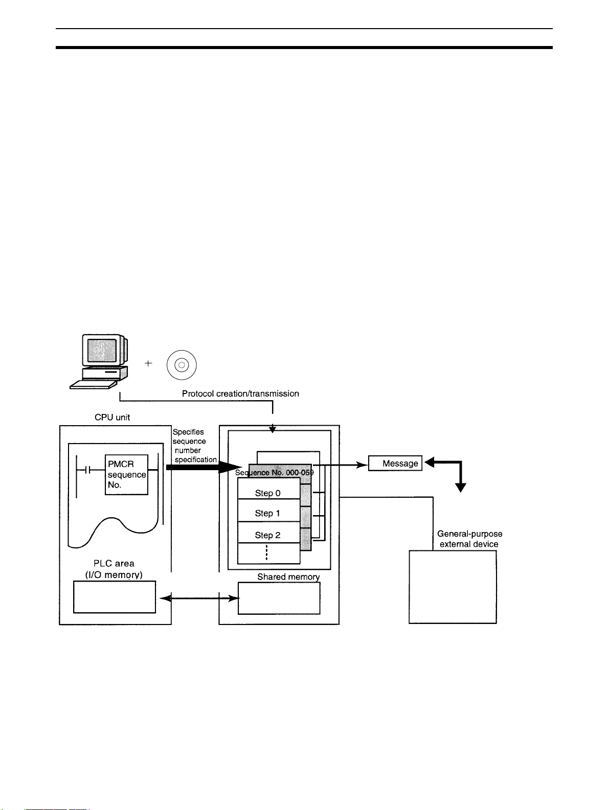
The CX-Protocol is the software for creating a procedure (or protocol) for
sending or receiving data to or from general-purpose external devices connected to a Protocol Macro Support Unit (PMSU) through RS-232C or RS485A/422.
A protocol consists of a set of communications sequences. CX-Protocol transfers a protocol to the PMSU, specifies the sequence number of the protocol
using the PMCR instruction on the CPU Unit, and executes the communications sequence.
The communications sequence consists of several steps and allows the user
to iterate, branch, or end these steps according to the result of the process.
Note 1. In the following section, the Communications Board for the C200HX/HG/
HE, Serial Communications Board for the CS and CQM1H, and Serial
Communications Units for the CS/CJ are referred to as the “PMSU.”
2. The CJ-series protocol macro function of the CJ-series Serial Communications Unit is used even for the system configuration described below,
which uses a CP-series CPU Unit with a CJ-series Serial Communications
Unit. The CJ Series is thus specified in descriptions unless there is information unique to the CP Series.
1-2 Features
Programming
Device
servicing
CX-Protocol
Protocol
Sequence No. 060-099
PMSU
Command execution (Send, Receive, or Send&Receive)
RS-232C or
RS-422A/485
1-2-1 Features of the Protocol Macro Function
Support for a wide range of communications protocols
Supports communications with almost all external general-purpose devices
that have RS-232C or RS-422A/485 ports and support half-duplex or fullduplex mode (full-duplex is for CS/CJ only) and start-stop synchronization
2
Page 29

Fe atu re s Section 1-2
mode (refer to 4-1 Applicable Range of the Protocol Macro Function for
restrictions).
Creation of send frames and receive (expected) frames according to the desired communications
frame specifications
Enables creation of almost all send frames (frames composed of commands,
data, and so on) and receive (expected) frames (frames composed of
responses and so on) according to the communications frame (message)
specifications of external devices.
Support for operation functions relating to communications
Supports error check code calculation, frame length calculation during transmission process, and numeral data conversion between ASCII and hexadecimal.
Support for the send and receive time monitoring function
Supports the receive wait monitoring, receive finish monitoring, and send finish monitoring functions. This function lets you designate whether to finish
send/receive process or to start retry process when those monitoring times
are exceeded.
Support for retry process Lets you designate, only by designating the number of retries, whether to
automatically execute send/receive retries when an error occurs.
Integration of variables for read/write process with PLC into send frames and receive (expected)
frames
Enables integration of variables for read process from PLC’s I/O memory into
send frames (messages) themselves. Data in the PLC that has been read
during transmission process can be used for addresses (destinations) or data.
This function also enables integration of variables for write process to PLC’s I/
O memory into receive frames (messages) themselves. Addresses (destinations) or data can be written into the PLC during the receive process.
Easy realization of rich functions including 1:N communications and switching data write destinations,
using repetition variables
Lets you designate repeat variables for send/receive process (repeat counter)
in variables. With this function, a wide variety of process can be easily realized: for example, sending the same data to multiple addresses (destinations)
by switching them during 1:N communications; switching write destination
addresses in PLC’s I/O memory during data receive process.
Execute interrupt program on the PLC while receiving data
Enables interrupt program execution on the PLC (CPU Unit) while receiving
data. The interrupt function is supported only by the Communications Board
for the C200HX/HG/HE and Serial Communications Board for the CS. It cannot be used with the Serial Communications Unit for the CS/CJ.
Switch the next process depending on the received data
The next process can be switched according to the data comparison with the
data registered to the maximum of 15 types.
The following functions have been added to the protocol macro for the CS/CJ.
Error check code (only for the CS/CJ protocol macro)
LRC2 (2’s complement of LRC) and SUM1 (1’s complement of SUM) have
been added to the error check codes.
3
Page 30

Features Section 1-2
Wait command to keep the next process on standby until a synchronous signal is input from the PLC
(only for the CS/CJ protocol macro)
During the send/receive sequence step, the next process can be kept on
standby until a synchronous signal is input from the PLC (CPU Unit). This
enables computation processing such as data processing on the CPU Unit
during the send/receive sequence.
Supports half-duplex and full-duplex transmission mode (only for the CS/CJ protocol macro)
The conventional protocol macro provides only the half-duplex macro. With
the half-duplex macro, the receive buffer is cleared right after the send operation, thus the received data cannot be used. With the full-duplex mode, all the
data received within the sequence can be used and data can be sent and
received at the same time.
Note The full-duplex mode can be used with the RS-232C or four-wire setting. It
cannot be used with the 1:N or two-wire setting. (Only for models with the RS422A/485.)
Clear data using Flush command within the receive buffer at any time (only for the CS/CJ protocol
macro)
With the full-duplex mode, the receive buffer is cleared only right before executing the send/receive sequence. If any reception error occurs, the received
data can be cleared at any time using the Flush command (receive buffer
clear).
Turn the DTR control signal ON and OFF using the Open/Close command (only for the CS/CJ protocol
macro)
When connected to a modem device, DTR signal is used to indicate that the
Serial Communications Board or Unit (DTE) is ready to send or receive data.
Previously, the DTR signal could be turned ON only during the send/receive
sequence.
Now the DTR signal can be turned ON or OFF at any time within the send/
receive sequence. This allows connection or disconnection with a modem
using the protocol macro.
The DTR signal can be set to ON even after the send/receive sequence has
completed. The DTR signal can be retained even after changing to another
protocol mode (for example, host link).
With this function, remote programming or monitoring can be performed
through a remote Programming Device by changing to the host link mode
using the STUP instruction after connecting to a modem.
1-2-2 Features of the CX-Protocol
Simultaneous display of tree (hierarchical) view and list (table) view
The CX-Protocol displays data in the form of a tree in the left pane, which
gives you easier understanding of the hierarchical structure of data you are
setting/monitoring.
Object-oriented operation Double-clicking target data, instead of choosing from menus, opens its corre-
sponding pop-up dialog, which enables you to create protocols quickly without
a thorough understanding of operation menus.
Supplied standard system protocols
Data exchange protocols for OMRON’s components (Temperature Controllers, Panel Meters, Bar Code Readers, Modems, and so on) are included as
standard system protocols.
Notice that those standard system protocols are included also in the PMSU.
4
Page 31

Checking the Contents of the Package Section 1-3
Possible to trace send/receive message
By executing the trace function from the CX-Protocol, the PMSU can trace
and save chronological data of send/receive messages up to 670 bytes for the
C200HX/HG/HE and up to 1,700 bytes for the CS/CJ. Each data item can be
displayed and printed for reading and saved as a trace file.
1-3 Checking the Contents of the Package
After purchase, first check the contents of your CX-Protocol package.
CX-Protocol Model
Product Name Model Setup disk
CX-Protocol WS02-PSTC1-E CD-ROM
CX-Protocol Components Check that all the following components of the CX-Protocol are included in
your package.
WS02-PSTC1-E
Item Quantity
Product Guide 1
Setup disk (CD-ROM) 1
Software license agreement and user
registration card for outside Japan
Software license agreement and user
registration card for within Japan
Seal 1
Notice sheet 1
1
1
1-4 Supported PLC Models and Personal Computers
1-4-1 Supported PLC Models
The CX-Protocol supports the following PLCs (Programmable Controllers).
Series CPU Unit
CS (See note 1.) CS1H-CPU67/66/65/64/63
CS1G-CPU45/44/43/42
CS1H-CPU67H/66H/65H/64H/63H
CS1G-CPU45H/44H/43H/42H
CS1D-CPU67H/65H
CS1D-CPU67S/65S/44S/42S
CJ CJ2H-CPU68/67/66/65/64/68-EIP/67-EIP/66-EIP/65-EIP/64-EIP
CP CP1H-XA@@@@-@
NSJ G5D (Same for the NSJ5-TQ@@-G5D, NSJ5-SQ@@-G5D, NSJ8-TV0@-G5D, NSJ10-TV0@-G5D,
C200HX/HG/HE
(See note 2.)
CQM1H
(See note 3.)
CJ1G-CPU45/44
CJ1G-CPU45H/44H/43H/42H
CJ1G-CPU45P/44P/43P/42P
CJ1H-CPU67H-R/66H-R/65H-R/64H-R/67H/66H/65H
CJ1M-CPU23/22/21/13/12/11
CP1H-X@@@@-@
CP1H-Y@@@@-@
and NSJ12-TS0@-G5D.)
M3D (Same for the NSJ5-TQ@@- M3D, NSJ5-SQ@@- M3D, and NSJ8-TV0@- M3D.)
C200HX-CPU34-E/44-E/54-E/64-E/34-ZE/44-ZE/54-ZE/64-ZE/65-ZE/85-ZE
C200HG-CPU33-E/43-E/53-E/63-E/33-ZE/43-ZE/53-ZE/63-ZE
C200HE-CPU-32-E/42-E/32-ZE/42-ZE
CQM1H-CPU51/61
5
Page 32

Supported PLC Models and Personal Computers Section 1-4
Note 1. When using the CS1D-H, set the device type as follows:
CS1D-H with unit Ver. 1.1: CS1D-H
Pre-Ver. 1.1 CS1D-H: CS1H-H
2. CX-Protocol Version 1.0 does not support the C200HX/HG/HE.
3. When using CQM1H-series PLCs, use the C200HG-CPU43 from the
C200HX/HG/HE Series as the CPU Unit.
1-4-2 Supported PMSUs
CS-series PLCs
Product name Installation Model Serial communications ports
Serial Communications
Boards (Inner Board)
Serial Communications
Unit (CPU Bus Unit)
Mounting the Serial Communications
Board on the CPU Unit
Installed in the CPU Unit
Installed on the CPU Rack
or CS Expansion Rack
CS1W-SCB21-V1 RS-232C port x 1 + RS-232C port x 1
CS1W-SCB41-V1 RS-232C port x 1 + RS-422A/485 port x 1
CS1W-SCU21-V1 RS-232C port x 1 + RS-232C port x 1
CS1W-SCU31-V1 RS-422A/485 port x 1 +
RS422A/485 port x 1
Mounting the Serial Communications
Unit on the CPU Rack
CPU Rack CPU Unit
Power Supply Unit
Serial Communications
Units
CS1 Expansion Rack
Power Supply Unit
CJ-series and CP-series
PLCs
Product name Classification Installation Model Serial communications ports
Serial Communications Unit
CJ-series CPU
Bus Unit
CPU Rack or
CJ Expansion Rack
CJ1W-SCU21-V1
CJ1W-SCU22
CJ1W-SCU31-V1
CJ1W-SCU32
CJ1W-SCU41-V1
CJ1W-SCU42
RS-232C port x 1 + RS-232C port x 1
RS-422A/485 port x 1 +
RS422A/485 port x 1
RS-232C port x 1 +
RS-422A/485 port x 1
6
Page 33

Supported PLC Models and Personal Computers Section 1-4
Connecting the Serial Communications Unit
• Mounting to a CJ-series CPU Unit
Power Supply Unit
CPU Unit
PA205R
POWER
AC100-240V
INPUT
OUTPUT
AC240V
DC24V
L1
L2/N
RUN
SYSMAC
CJ1G-CPU44
P
R
O
G
R
A
M
C
O
N
T
R
O
LL
M
A
B
L
E
R
OPEN
M
C
B
U
E
PW
R
S
Y
PERIPHERAL
PO
RUN
ERR/ALM
INH
PRPHL
COMM
R
T
Serial Communications Unit
• Mounting to a CP-series CPU Unit
CP1H CPU Unit
CP1W-EXT01
CJ-series Unit Adapter
SCU41
RUN
ERC
SD1
RD1
TER1
RDY
ERH
SD2
RD2
TERM
OFF
ON
UNIT
5
4
6
3
7
2
8
1
9
NO.
0
A
F
B
E
C
D
WIRE
2
4
PORT1
(RS422
/485)
PORT2
CJ1W-TER01
CJ-series End Cover
(Included with CJ-series
Unit Adapter)
C200HX/HG/HE PLCs
Product
name
PMSU
Installation Model Enhanced
Installed in
the CPU
Unit
Connect the Serial Communications
Unit to one of these.
Specifications
functions (see
note)
C200HW-COM04-E --- CPU bus interface + RS-232C port x 1
C200HW-COM04-EV1 ❍
With the protocol macro function
C200HW-COM05-E --- RS-232C port x 2
C200HW-COM05-EV1 ❍
With the protocol macro function
C200HW-COM06-E --- RS-232C port x 1 + RS-422A/485 port x 1
C200HW-COM06-EV1 ❍
With the protocol macro function
Note 1. The enhanced functions are as follows:
• SUM2 (2’s complement of SUM) and CRC-16 are added as error
check codes.
• Repeat counter N current value, Sequence End Finish Flag, and Sequence Abort Finish Flag are added to the auxiliary area.
• A check code can be located behind a terminator in messages.
• Swap between high byte and low byte can be designated for error
check codes.
7
Page 34

Supported PLC Models and Personal Computers Section 1-4
CPU Unit
Communications Board
2. Mounting the Communications Board on the CPU Unit
■ Caution in Using Communications Board for SYSMAC Alpha
When using Communications Board for SYSMAC Alpha with either of the
communications ports set to NT link (1:N), you cannot transfer protocol data
to the other port by using CX-Protocol.
When you want to transfer protocol data to the Communications Board, set its
communications port to any of the settings other than NT link (1:N) before
transfer, and set it to NT link (1:N) after transfer before using the Communications Board.
CQM1H
Product name Installation Model Serial communications ports
Serial Communications
Boards
Installed in the CPU Unit CQM1H-SCB41 RS-232C port x 1 + RS-422A/485 port x 1
CQM1H CPU Unit
PA203
P
O
W
E
R
R
U
N
E
R
R
/A
LM
IN
H
P
R
PH
L
C
O
M
M
PORT1
T
E
R
M
O
N
W
IR
E
2 4
PORT2
RS233
/485
S
C
B
4
1
CQM1H Serial Communications Board
01234567
8 9 10 11 12 13 14 15
0CH
■ Caution in Using CQM1H Serial Communications Board
When using CQM1H Serial Communications Board with either of the communications ports set to NT link (1:N), you cannot transfer protocol data to the
other port by using CX-Protocol.
When you want to transfer protocol data to the Serial Communications Board,
set its serial communications port to any of the settings other than NT link
(1:N) before transfer, and set it to NT link (1:N) after transfer before using the
Serial Communications Board.
Note The following restrictions exist when using the CX-Protocol to create and edit
protocol macros, transferring data between the Board and personal computer,
or performing other functions for the CQM1H.
8
Page 35

System Configuration Section 1-5
• Always turn ON pin 8 on the DIP switch on the front on the CQM1H CPU
Unit. (When pin 8 is ON, you will not be able to connect the peripheral
port, built-in RS-232C port, or serial communications ports on Boards
mounted in the CPU Unit to the CX-Programmer or other Support Software running on a personal computer.)
• Set the device type to “C200HG” and the CPU type to “CPU43.”
• Other than these restrictions, functionality will be the same as for the
C200HX/HG/HE PLCs.
1-4-3 Supported Personal Computers
Item Minimum Requirements Recommended
Personal computer IBM PC/AT or compatible
CPU Pentium II 333 MHz or faster Pentium III 1 GHz or faster
Operating system Microsoft Windows 2000 (Service Pack 2 or higher), XP, Vista,
or Windows 7
Memory 256 MB minimum (512 MB
minimum for Windows Vista or
Windows 7)
Hard disk drive 300 MB or more available space
Display SVGA (800 x 600) or better
Floppy disk drive One drive min. (for 1.44 MB)
CD-ROM drive One drive min.
512 MB minimum (1 GB minimum for Windows Vista or
Windows 7)
1-5 System Configuration
1-5-1 Connecting the CX-Protocol and the PLC
For the CS/CJ Connect the peripheral port on the CPU Unit to the built-in RS-232C port.
Note Can be connected to the PMSU port if the port is set to the host link mode.
Connection to a IBM PC/AT or
compatible computer
Peripheral port connection
9-pin
CS1W-CN226 (2.0 m)
CS1W-CN626 (6.0 m)
Note When using the RS-232C Cable to connect to a CPU Unit peripheral port, as
Peripheral port
on the CPU Unit
shown below, use the CS1W-CN118.
RS-232C port connection
9-pin
XW2Z-200S-V (2.0 m)
XW2Z-500S-V (5.0 m)
9-pin
RS-232C port on the
CPU Unit or PMSU port
(host link mode)
9
Page 36

System Configuration Section 1-5
XW2Z-
(((S-(
RS-232C Cable
CS1W-CN118
Peripheral port
When combining the CS1W-CN118 with the RS-232C Cable, connections
cannot be made using the Toolbus. Make connections using Host Link
(SYSWAY).
CP Series
Computer Computer port CPU Unit port Cable length Cable
IBM PC/AT or
compatible
USB port
(A-type connector)
IBM PC/AT or
compatible
USB port
(B-type connector
5 m max. Commercially
available USB
1.1 or 2.0 cable
USB port
Commercial
USB cable
Peripheral USB port
CP1H
CPU Unit
Note If an RS-232C Option Board (CP1W-CIF01) is mounted, it is also possible to
use a XW2Z-200S/500S-V/-CV RS-232C Cable to connect an RS-232C port
on the computer to the RS-232C Option Board.
For the C200HX/HG/HE Connect the peripheral port on the CPU Unit to the built-in RS-232C port.
Note Can be connected to the PMSU port if the port is set to the host link mode.
Connection to a IBM PC/AT or
compatible computer
Peripheral port connection
9-pin
Peripheral port
on the CPU Unit
RS-232C port connection
9-pin
(see note)
RS-232C port on the
CPU Unit or PMSU port
(host link mode)
10
CQM-CIF02
Connecting Cable
XW2Z-200S (2.0 m)
XW2Z-500S (5.0 m)
9-pin
Note For IBM PC/AT or compatible computers, a conversion connector from D-sub
25P (female) to 9P (female) is required for the personal computer side connector.
Page 37

System Configuration Section 1-5
1-5-2 Connecting the PLC to External Devices
For the CS/CJ The following figure shows the system configuration of the PMSU in the PLC
and external devices. The RS-232C port provides 1:1 connection and the RS422A/485 port 1:N connection.
CS1W-SCU21-V1 Serial Communications Unit CS1W-SCB41-V1 Serial Communications Board
Por t 1
Por t 2
RS-232C
General-purpose
external device
General-purpose
external device
CPU Unit
RS-232C
Por t 1
RS-422A/485
Por t 2
RS-232C
General-purpose
external device
General-purpose
external device
General-purpose
external device
Types of PMSUs
Communications function
Host link NT link
(see note)
Host computer programming
devices
❍❍
PT None
Model Name Model
Serial
Communications
Boards
Serial
Communications
Units
CS1W-SCB21-V1
CS1W-SCB41-V1
CS1W-SCU21-V1
CS1W-SCU31-V1
CJ1W-SCU21-V1
CJ1W-SCU22
CJ1W-SCU31-V1
CJ1W-SCU32
CJ1W-SCU41-V1
CJ1W-SCU42
Devices to be connected
Communications
port
RS-232C (port 1) ❍❍❍❍
RS-232C (port 2) ❍❍❍❍
RS-232C (port 1) ❍❍❍❍
RS-422A/485
(port 2)
RS-232C (port 1) ❍❍❍❍
RS-232C (port 2) ❍❍❍❍
RS-422A/485
(port 1)
RS-422A/485
(port 2)
RS-232C (port 1) ❍❍❍❍
RS-232C (port 2) ❍❍❍❍
RS-422A/485
(port 1)
RS-422A/485
(port 2)
RS-232C (port 1) ❍❍❍❍
RS-422A/485
(port 2)
Protocol
macro
❍❍
❍❍❍❍
❍❍❍❍
❍❍❍❍
❍❍❍❍
❍❍❍❍
General-
purpose
external
devices
Cyclical
test
Note Cannot be used with two-wire models.
11
Page 38

System Configuration Section 1-5
For the C200HX/HG/HE The following figure shows the system configuration of the PMSU and exter-
nal devices. The RS-232C port provides 1:1 connection and the RS-422A/485
port provides 1:N connection.
CPU Unit
C200HW-COM06-EV1 Communications Board
Por t B
RS-422A/485
Por t A
Types of PMSUs (Only Models Having the Protocol Macro Function)
Communications Function
No-
procedural
❍
2)
❍
(see note
2)
General-
purpose
external
devices
Model
C200HW-COM04-
E/EV1
C200HW-COM05-
E/EV1
C200HW-COM06-
E/EV1
Devices to be connected
Communications
port
CPU bus interface --- --- --- --- --- ❍
RS-232C (port A) ❍❍❍❍❍---
RS-232C (port A) ❍❍❍❍❍---
RS-232C (port B) ❍❍❍❍❍---
RS-422A/485 (port
A) ❍
RS-232C (port B) ❍❍❍❍❍---
Protocol
macro
General-
purpose
external
devices
Host link
(see note
Host com-
puter pro-
gramming
devices
RS-232C
General-purpose
external device
General-purpose
external device
General-purpose
external device
1:1 link
❍
(see note
2)
PLC PT
General-purpose
external device
NT link
1:1, 1:N
❍ ---
CPU bus
Interface
with Com-
munica-
tions Units
12
Note 1. C200HW-COM@@-EV1: Enhanced function model
2. Not available for two-wire models.
Page 39

Protocol Macro Section 1-6
1-6 Protocol Macro
1-6-1 Protocol Macro Outline
Protocol macro is a function that creates macros for communications protocols that conform to specifications for communications between general-purpose external devices that have a serial communications port.
Generally the protocol macro performs two kinds of function:
• Creation of communications frames (messages).
• Creation of procedures for sending and receiving communications frames
(messages).
Creation of Communications Frames (Messages)
1,2,3... 1. Communications frames, referred to here as “messages” and which can be
understood by general-purpose external devices, can be created according to the communications specifications.
Header Address Data Check
code
Terminator
Note In general, the data area of a send message contains a command code and
data. The data area of a receive message contains a response code.
2. Variables for reading data from (or writing data to, if receiving) the I/O
memory (data memory, for example) of the CPU Unit, can be integrated
into the messages.
I/O memory
Read
Send
Variable R ( )
Variable W ( )
Receive
Write
I/O memory
This function has the following advantages:
• Ladder program processing will not be necessary at the CPU Unit
when, for example, sending messages after arranging them all in data
memory.
CPU Unit
Not necessary
Header
Address
Send
13
Page 40

Protocol Macro Section 1-6
• The components of the previously created messages are stored in
memory at the PMSU, not the CPU Unit. When sending or receiving
data, the CPU Unit only has to execute the PMCR instruction.
CPU Unit
PMCR instruction
CPU Unit
PMSU
Message
Send
Receive
• When handling one part of the I/O memory data, if the variable required for reading that data has been integrated into a send message,
the PMSU will automatically read the required data from the I/O memory of the CPU Unit when the PMSU sends the message. Similarly,
when writing data from one part of a received message into I/O memory, if the variable required to read the data has been integrated into
the reception settings message, the PMSU will automatically write the
data at the designated position in the message into I/O memory when
the PMSU receives the message.
PMSU
PMCR instruction
I/O memory
CPU Unit
PMCR instruction
I/O memory
Send message
Reads I/O memory data
PMSU
Receive message
Writes to I/O memory
14
Page 41

Protocol Macro Section 1-6
Creating Procedures for Sending and Receiving Communications Frames (Messages)
1,2,3... 1. This function enables all the processing needed to send or receive a mes-
sage to be handled as one step, and possesses all the commands (step
commands), such as Send, Receive, Send&Receive and Wait, that are
needed for each step.
CPU Unit
PMCR instruction
CPU Unit
PMCR instruction
PMSU
General-purpose
external device
Step 0
Step 1
2. This step can be set so that the next process (step/end) depends on the
processing result of the previous step. In particular, it is possible to set the
sequence so that the next process depends on the contents of one or several set receive messages.
PMSU
General-purpose
external device
Step 0
Next step depends
on contents of re-
ceived data
Step n (depending on contents of received data)
Note 1. A send message created with a protocol macro will perform settings for
messages that are actually sent.
2. A receive message created with protocol macro will set an expected message for comparison with messages that are actually received.
Send
Sets message being sent
Message received
Receive
Sets expected message for comparison
(Send)
(Receive)
15
Page 42

Protocol Macro Structure Section 1-7
1-6-2 Standard System Protocol
Data exchange protocols (called standard system protocols) for OMRON
Units (Temperature Controllers, Panel Meters, Bar Code Readers, Modems,
etc.) have been installed into the PMSU. By setting the prescribed receive/
send data and executing the PMCR instruction, therefore, data exchange can
be easily performed with OMRON Units.
1-7 Protocol Macro Structure
The protocol consists of a communications sequence (“sequence” in short),
which is an independent process for the general-purpose external device (for
example, reading a process variable from a Temperature Controller). One
sequence consists composed of some steps, each of which is composed of a
Send, Receive, or Send&Receive command, send/receive message, branch
or end according to the result of the process.
For example, the sequence to read a process value from the temperature controller sends to the controller a send message (a string containing the read
command with a header, address, check code, and terminator), and then
receives a receive message (a string containing a response to the read command with a header, address, check code, and terminator).
Protocol Macro Suppor t Unit
RX00
RX01
:
Terminator
RS-232C or
RS-422A/485
:
16
Page 43

Protocol Macro Structure Section 1-7
The sequence determines, according to the result of process, whether to send
the same send message again (called retry) or execute the next process
(reading process value from the Temperature Controller linked to another
address, etc.), for example.
Transmis-
sion control
parameter
Link word
Monitoring
timer
Response
Ty pe
Message lists (see note 2)
Send message list
Header Address Data Check Terminator
Receive message list
Structure of one step
(for Send. Receive, Send&Receive commands)
Command
(Note 1)
Message
(Note 2)
Normal end?
To b e
repeated?
Y
Next process
N
(Error)
Y
N (Not repeated)
Y
To b e
retried?
N (Not retr
Error process
(For Wait, Flush, Open,
Close commands)
Command (Note 1)
Next process
ied)
Header Address Data Check Terminator
Matrix (see note 2)
Case No. 15
Case No. 00
Receive message
Next process
Note 1. The command is Send, Receive, Send&Receive, Wait, Flush, Open, or
2. There are three types of messages: send messages, receive (expected)
Close.
• A step can be retried with the Send&Receive command.
• A step can wait to transmit a send message upon the Send or
Send&Receive commands.
• A step can select the next process according to the content of the received message by using a matrix.
messages, and matrices that switch processes according to multiple receive (expected) messages. Those messages are managed by lists and
separated from sequences.
17
Page 44

Protocol Macro Structure Section 1-7
1-7-1 Step Structure
Each step has the fixed processing framework as follows. Users create protocols by setting parameters for each framework.
One step contains one command (Send, Receive, Send&Receive, Wait,
Flush, Open, or Close) and one or two messages (send, receive, or send/
receive). The step changes from one to another by the Next Process within
the step.
Sequence
Step 00
Step 01
Step n
on to steps)
m
(com
Sequence unit setting
Step 15
Next process
Next process
Structure of one step
(for Send. Receive, Send&Receive commands)
Command
Message
Y
Normal end?
Y
Next process
Y
To be
repeated?
N
N
To be
retried?
N
Error process
(For Wait, Flush, Open,
Close commands)
Command
Next process
Note The Wait, Flush, Open, and Close commands are for the CS/CJ protocol mac-
ros. (They are not supported by the C200HX/HG/HE protocol macros.)
Setup Parameters that Commonly Affect Steps (in Each Sequence)
Parameter Description
Transmission control parameter Sets the control mode for control signals including flow control.
Link word Sets area in which data is shared between the PLC and the PMSU.
Monitoring time Sets monitoring time for send and receive process.
Response type Sets timing of writing receive data into PLC’s I/O memory.
Setup Parameters for Each Step
Parameter Setup content
Command Send, Receive, Send&Receive, Wait, Flush, Open, or Close
Send message Sets message to be sent for the Send command.
Receive message Sets message expected to be received for the Receive command.
Message
receive message
Matrix
Repeat counter
Retry count
Send wait time
With/Without Response Writing Specifies whether to write received data.
Next process Sets the next step to which the step transits or the sequence exits if it ends normally.
Error process
Send message and
Sets messages to be sent and expected to be received for the Send&Receive
command.
Selects the next process according to the content of the received message when the
command is Receive or Send&Receive and up to 15 messages can be expected to
be received.
The number of times iterating the step (0 to 255). Using this parameter N allows to
change the content of send and receive messages.
(Used only for Send&Receive command)
Retries the command when a retry cause such as an error occurs (0 to 9 times).
(Used only for Send or Send&Receive command)
Set the waiting time before starting to send data.
Sets the next step to which the step transits or the sequence exits if it ends
abnormally.
18
Page 45

Data Created by the CX-Protocol Section 1-8
1-8 Data Created by the CX-Protocol
The CX-Protocol creates/manages data by file unit, called “project.”
Project files consist of the following data:
1 project file
Note 1: Protocol
(1 protocol)
Protocol list
Protocol list
Protocol list
Trace list
PLC
Sequence
Sequence
Sequence
Protocol
Protocol
Protocol
Up to 20 protocols (see note 1)
(Up to 1,000 sequences/PLC)
Up to 60 sequences (see note 2)
(The first sequence number and
the last sequence number are
designated for each protocol.)
Send message list
Receive message list
Matrix list
Note 2: Sequence#@@@
Message
Message
Message
Message
Matrix
Matrix
Up to 300 messages
Up to 100 matrices
Step 00
Step 01
Step 15
Up to 16 steps
Project files are stored with a file extension .PSW.
Note To transfer standard system protocols to the PMSU or create a new protocol
by partially modifying one of the standard system protocols, first copy the
required standard system protocol to another project file and then use the
project file. The standard system protocols themselves cannot be edited or
transferred.
The standard system protocols have been installed into the PMSU at our factory.
Files that can be Read or Written by CX-Protocol
Type of file Content File
extension
CX-Protocol/SYSMAC-PST
project files (see note)
CX-Protocol project files consist of the
following:
*.PSW Yes Yes
Protocol data
PLC (communications conditions between
PLC and personal computer, communications
port (A/B) setting of the PSB or the port (1/2)
setting of the Serial Communications Board/
Unit)
Trace data
PSS system setting file File that contains communications port (A/B)
*.pts Yes No
setting data of the PSS Protocol Macro
Support Unit
PSS protocol file File that contains only PSS protocol data *.pt1 Yes No
Trace data file File that contains only trace data *.ptr Yes No
Read Write
19
Page 46

Main Screens of the CX-Protocol Section 1-9
Note CX-Protocol project files cannot be read by the PSS (DOS version of Protocol
Support Software) or the SYSMAC-PST.
Refer to 11-3 Importing Protocol Data from PST/PSS Files for loading PST
project files or PSS files.
1-9 Main Screens of the CX-Protocol
The CX-Protocol displays the tree view of the hierarchical data structure in the
left pane. For the highlighted data in the left pane, the list view of its contents
is displayed in the right pane.
Contents of a Project A project consists of protocol list, trace list, and PLC.
Display of Sequences in a Protocol
A protocol consists of sequences.
20
Page 47

Main Screens of the CX-Protocol Section 1-9
Display of Each Step in a Sequence
A sequence consists of steps and their setup parameters for each sequence
(transmission control parameter and so on).
Display of Messages in a Message List
Messages are managed separately from sequences. Messages can be
referred to by their names from each step in a sequence.
Display of Cases in a Matrix
Matrices are managed separately from sequences. Matrices can be referred
to by their names from each step in a sequence.
21
Page 48

Main Screens of the CX-Protocol Section 1-9
Display of Trace Data
Displays the send and receive messages in chronological order up to the
maximum of 1,700 bytes (characters) for the CS/CJ and 670 bytes (characters) for the C200HX/HG/HE.
22
Page 49

Overview of Project Creation Section 1-10
1-10 Overview of Project Creation
Project creation from scratch
PLC model change
PLC Setup
Protocol creation (addition to list)
Protocol sequence number range setting
Designate the following: Protocol name,
sequence start number, sequence end
number, target.
Sequence creation
Designate the following: link word,
transmission control parameter,
response type, and monitoring time
(Tr, Tfr, Tfs).
Step creation
Designate the following: repeat counter,
command, retry count, send wait time,
send message (note), receive message
(note), with/without response writing, next
process, and error process.
Menu Operation/Icon Operation
Select New from the File menu
Display after creating new project.
Select Edit PC-PLC Comms Settings from the PLC
menu. Designate target PLC model, Personal Computer ↔ PLC Communication Settings.
Double-click the PMSU icon. Designate setup
items for each of ports 1(A) and 2(B).
Right-click Create/Protocol.
Right-click Create/Sequence.
Right-click Create/Step.
Note: Ports in parentheses
are for the C200HX/HG/HE.
Refer to
SECTION 5-1
SECTION 10-1/10-2
SECTION 10-1/10-2
SECTION 5-1
SECTION 5-1
SECTION 5-2
SECTION 7
SECTION 5-2
SECTION 8
Message creation
Header, terminator, check code, length,
address, message edit (including data)
Matrix creation
Protocol transfer (from personal computer to PMSU)
Note 1. A send message in a step can be designated by choosing its message
name in the send message list.
2. A receive message in a step can be designated by choosing its message
name in the receive message list or matrix name in the matrix list.
3. Therefore, you can create a message part during step creation more easily
by choosing a message name of the desired send message, receive message, or matrix that you have created in advance.
Right-click the Send Message or
Receive Message field in the step
list, and select New Message
from the pop-up menu.
Right-click Create/Matrix and
Create/Matrix Case.
SECTION 5-3
SECTION 9
SECTION 11-1
23
Page 50

Incorporated Standard System Protocol Section 1-11
1-11 Incorporated Standard System Protocol
The CX-Protocol together with the PMSU provides the following 13 types of
incorporated standard system protocols. (There are 12 types for the Communications Board of the C200HX/HG/HE because it does not support CompoWay/F.)
The protocols can be displayed by selecting the System Tab of the project
workspace.
Note To transfer standard system protocols to the PMSU or create a new protocol
by partially modifying one of the standard system protocols, first copy the
required standard system protocol to another project file and then use the
project file. The standard system protocols themselves cannot be edited or
transferred.
The standard system protocols have been installed into the PMSU at our factory.
Protocol name Function
CompoWay/F Protocol for sending a CompoWay/F command and receiving responses from the devices incorpo-
Controller
(E5_K read)
Controller
(E5_K write)
Temp Controller
(E5ZE read)
Temp Controller
(E5ZE write)
Temp Controller
(E5_J)
Controller (ES100_) Protocol for controlling a ES100@ Temperature Controller via the PMSU. Procedures for writing
Intelligent Signal Processor (K3T_)
Bar Code Reader
(V500/V520)
Laser Micro Meter
(3Z4L)
Visual Inspection
System (F200/300/
350)
ID Controller (V600/
620)
Hayes modem AT
commands
rating the CompoWay/F protocol (Slave function). This protocol operates only with the CS/CJ.
Protocol for controlling an E5@K Digital Controller via the PMSU. Procedures for reading the MV
and operating parameter setting.
Protocol for controlling an E5@K Digital Controller via the PMSU. Procedures for writing set points
and operating parameters.
Protocol for controlling an E5ZE Temperature Controller via the PMSU. Procedures for reading
measured temperature and operating parameter setting.
Protocol for controlling an E5ZE Temperature Controller via the PMSU. Procedures for writing
control temperatures and operating parameters.
Protocol for controlling a E5@J Temperature Controller via the PMSU. Procedures for writing set
points, reading output amounts, and reading/writing operating parameters.
adjustment parameters, reading operation amounts, and writing/reading operating parameters.
Protocol for controlling a Digital Panel Meter via the PMSU. Procedures for writing comparison val-
ues and reading display values are set.
Protocol for controlling a Bar Code Reader via the PMSU. Procedures for controlling the Bar Code
Reader in remote mode, reading the data that has been read by the Bar Code Reader, and
reading/writing operating parameters.
Protocol for controlling a Laser Micrometer via the PMSU. Procedures for controlling the Laser
Micrometer in remote mode, reading measured data, and writing/reading operating parameters.
Protocol for controlling a Visual Inspection System via the PMSU. Procedures for controlling the
Visual Inspection System in remote mode, reading measured values, and writing/reading
operating parameters.
Protocol for controlling an ID Controller via the PMSU. Procedures for performing Read/Write
operations of the ID Controller and writing/reading operating parameters.
Protocol for controlling a Hayes modem (AT commands) via the PMSU. Procedures for
initialization of the modem, dialing, data transmission, switching to escape mode, and
disconnecting the line.
For more information on each protocol, refer to the C200HX/HG/HE Commu-
nications Board Operation Manual (W304), CS/CJ Series Serial Communications Board/Unit Operation Manual (W336), and CQM1H Series Serial
Communications Board Operation Manual (W365).
Example: Protocol for the Controller (E5_K read)
Sequence No. Communications sequence
000 Read process value
001 Read set point during SP ramp
002 Read MV
003 Read set point
004 Read alarm value
005 Read proportional band, integral time, and derivative time
24
Page 51

Basic Procedure of the Protocol Macro Usage Section 1-12
g
1-12 Basic Procedure of the Protocol Macro Usage
1-12-1 For the CS/CJ
Procedure 1 PMSU Setup
Setting the Serial Communications Board
(for Serial Communications Boards with
RS-422A/485)
Terminating resistance ON/OFF switch
2-wire/4-wire Selection switch
Setting the Serial Communications Unit
Front rotary switch setting
Unit No. setting switch
Procedure 2 PMSU Mounting
Set the unit No. in a ran
Mounting the Serial Communications Board Mounting the Serial Communications Unit
e from 0 to F (0 to 15).
25
Page 52

Basic Procedure of the Protocol Macro Usage Section 1-12
Procedure 3 Connection with External Devices
CS1W-SCU21-V1 Serial Communications Unit
CPU Unit
CS1W-SCB41-V1 Serial Communications Board
RS-232C RS-232C
General-purpose
external device
Por t 1
Por t 2
General-purpose
external device
Por t 1
Por t 2
RS-422A/485
RS-232C
General-purpose
external device
General-purpose
external device
Note For connector pin arrangements and connection methods, refer to the CS/CJ
Series Serial Communications Boards/Unit Operation Manual (W336) and
other relevant manuals for general-purpose external devices.
Procedure 4 Initial Setting
1,2,3... 1. For Connecting Cables between the PLC and the CX-Protocol, refer to
1-5 System Configuration.
2. PLC Setup of the CPU Unit and the PMSU.
PLC Setup for Connecting the PLC to the CX-Protocol.
Perform the following setups (a) and (b). The communications conditions
designated in (a) and (b) must be coherent.
a) Using the CX-Protocol, designate a target PLC model and perform the
communications setup between the personal computer and the PLC.
b) Using a Programming Device for PLC’s CPU Unit, perform the PLC
setup according to a connected port.
PLC Setup of the Serial Communications Board PLC Setup of the Serial Communications Unit
Allocated DM area: D32000 to D32767 Allocated DM area: D30000×100 Unit No.
D32000 to D32009
D32010 to D32019
D32020 to D32767
PLC setup of port 1
PLC setup of port 2
Reserved by the system
Unit No.
0
1
2
3
4
5
6
7
8
9
A
B
C
D
E
F
DM area
D30000 to D30099
D30100 to D30199
D30200 to D30299
D30300 to D30399
D30400 to D30499
D30500 to D30599
D30600 to D30699
D30700 to D30799
D30800 to D30899
D30900 to D30999
D31000 to D31099
D31100 to D31199
D31200 to D31299
D31300 to D31399
D31400 to D31499
D31500 to D31599
General-purpose
external device
m to m+9: PLC setup of port 1
m+10 to m+19: PLC setup of port 2
m+20 to m+99: Not used
Example: Setting the Default Communications Conditions (m=D30000+100×Unit No.)
Board Unit Bits Settings
Port 1 Port 2 Port 1 Port 2
D32000 D32010 m m+10 15 0: Start bit=1 bit, Data length=7 bits, Parity=Even, Stop bit=2 bits
11 to 08 6: Protocol macro
D32001 D32011 m+1 m+11 03 to 00 0: Baud rate: 9600 bits/s
D32008 D32018 m+8 m+18 15 0: Half-duplex
D32009 D32019 m+9 m+19 15 to 00 00C8 Hex: Protocol send/receive data bytes: 200 bytes max.
26
Page 53

Basic Procedure of the Protocol Macro Usage Section 1-12
Using the CX-Protocol, make the settings for communications ports 1 and 2 of
the PMSU and transfer the settings to the PLC.
For more information, refer to 10-6 PMSU Communications Port Settings and
10-7 Transfer of Communications Port Setting Data to PLC.
3. External Device Settings
Perform required processes including DIP switch settings on external de-
vices.
Procedure 5 Protocol Design
Refer to the SECTION 4, SECTION 5, and SECTION 6.
1,2,3... 1. Creates the status transition chart of the communications sequence.
2. Disassembles the status transition chart into sequences and steps, and
set them up.
3. Creates the send and the receive messages.
Procedure 6 Project (Protocol Data) Creation and Transfer by CX-Protocol
Refer to 1-10 Overview of Project Creation.
1,2,3... 1. Creates a new project.
Refer to 5-1 Creating Projects and Protocols.
2. Creates a new communications sequence.
Refer to 5-2 Creating Sequences and Steps and7-1 Setting Sequences.
3. Creates each step.
Refer to 5-2 Creating Sequences and Steps and 8-1 Step Setting.
4. Creates each message. (See note.)
Refer to 9-1 Creating Messages.
5. Transfers the created projects to the PMSU.
Refer to 11-1 Transferring and Reading Protocol Data between the Com-
puter and PMSU.
Note Each step can be created after each message creation by designat-
ing the message name.
Procedure 7 The Ladder Program Creation
1,2,3... 1. Allocates a function code for the PMCR instruction.
Example: For the Serial Communications Board
Input condition
Protocol Macro
Execution Flag
191915
Communications Port
Enabled Flag
A20207
When the input condition is set to “ON” and the Protocol Macro Execution
Flag (191915: port 2) is set to “OFF,” the communications sequence number 100 registered on the PMSU is called to send and receive data via port
2 of the PMSU if the Communications Port Enabled Flag (A20207: internal
logic port of the communications port No. 7 is used) is ON.
The send data is sent out from the next D00001 according to the number
of effective words (number of words including D00000) designated by
D00000.
D00000
D00001
Number of effective words
PMCR (260)
Send data
#72E1
#0064
D00000
D00100
Use communications port No. 7 and
serial port No. 2.
Destination unit number address E1:
Inner (serial communications) Board
Sequence No. 100
Send data first word
Receive data storage first word
How many words including
D0000 are effective?
Designated number at D00000
Effective
words
of send data are read beginning
from D00001.
27
Page 54

Basic Procedure of the Protocol Macro Usage Section 1-12
The receive data is stored in the successive words beginning from D00101
for the number of effective words actually stored in D00100 (number of
words including D00100).
D00100
D00101
Number of effective words
Receive data
Effective
words
How many words including
D00100 are effective?
Receive data is stored in
successive words beginning
from D00101 and the number of
effective words is stored in
D00100.
Note Receive data set before the PMCR is executed will not change if re-
ceive processing fails.
2. Execute the PMCR instruction.
Procedure 8 Confirmation of Operations
Refer to SECTION 12 Tracing and Monitoring.
1,2,3... 1. Traces the transmission lines.
Trace the data in the send and receive messages and the control signals
that are flowing on the transmission line (RS-232C or RS-422A/485).
2. Monitors the I/O memory.
Monitor the send and the receive data and the status of flags.
1-12-2 For the C200HX/HG/HE
Procedure 1 PMSU Setup DIP Switch Setup for the PMSU (For C200HW-COM06-E/EV1 only.)
SW1: Switch between two-wire and four-wire methods
SW2: ON/OFF of terminating resistance (ON during using RS-422A/485
ports)
Procedure 2 PMSU Mounting
1,2,3... 1. Open the memory cassette cover.
28
Page 55

Basic Procedure of the Protocol Macro Usage Section 1-12
2. Remove the PMSU cover.
3. Insert the PMSU and slide it into the slit completely.
4. Close the memory cassette cover.
Procedure 3 Connection with External Devices
Connect through RS-232C or RS-422A/485.
Protocol Macro Support Unit
RS-232C
RS-422A/485
29
Page 56

Basic Procedure of the Protocol Macro Usage Section 1-12
Note For connector pin arrangements and connection methods, refer to the Com-
munications Board Operation Manual (W304) and other relevant manuals for
general-purpose external devices.
Procedure 4 Initial Setting
1,2,3... 1. For Connecting Cables between the PLC and the CX-Protocol, refer to
1-5 System Configuration.
2. PLC setup of the CPU Unit and the PMSU.
PLC Setup for Connecting the PLC to the CX-Protocol.
Perform the following setups (a) and (b). The communications conditions
designated in (a) and (b) must be coherent.
a) Using the CX-Protocol, designate a target PLC model and perform
communications setup between the personal computer and the PLC.
b) Using a Programming Device for PLC’s CPU Unit, perform PLC setup
according to a connected port.
• When connected to the peripheral port:
Communications setup of the peripheral port:
DM 6650 to DM 6654 in the PLC setup area
• When connected to the CPU Unit’s built-in RS-232C port:
Communications setup of the RS-232C port:
DM 6645 to DM 6649 in the PLC setup area
For both the peripheral port and the CPU Unit’s built-in RS-232C port,
make the default settings (start bit: 1 bit, data length: 7 bits, parity: even,
stop bit: 2 bits, baud rate: 9600 bps) to correspond to 0000 in DM 6650 for
the peripheral port and DM 6645 for the CPU Unit’s built-in RS-232C port
respectively.
PLC Setup for the PMSU
Use one of the following methods to perform PLC setup of the PMSU port
A/B.
c) Using a Programming Device for the PLC’s CPU Unit, perform the fol-
lowing PLC setup.
PMSU PLC setup
Port A: DM 6555 to DM 6559 in the PLC setup area
Port B: DM 6550 to DM 6554 in the PLC setup area
30
Example: Setting the Default Communications Conditions
15 0
DM6555
6000
Communications conditions of Port A
0 indicates:
Start bit:1 bit, data length: 7 bits, parity:
even, stop bit: 2 bits, baud rate: 9,600 bps
Communications mode for port A
6: Protocol macro
d) Using the CX-Protocol, perform setup of communications port A/B
through the PMSU Icon and transfer the setting to the PLC.
For more information, refer to 10-7 Transfer of Communications Port
Setting Data to PLC.
3. Setup of external devices.
Perform required processes including DIP switch settings on external de-
vices.
Page 57

Basic Procedure of the Protocol Macro Usage Section 1-12
Procedure 5 Protocol Design
Refer to SECTION 4, SECTION 5, and SECTION 6.
1,2,3... 1. Creates the status transition chart of communications sequence.
2. Disassembles the status transition chart into the sequences and steps and
sets them up.
3. Creates the send and the receive messages.
Procedure 6 Project (Protocol Data) Creation and Transfer by CX-Protocol
Refer to 1-10 Overview of Project Creation.
1,2,3... 1. Creates a new project.
Refer to 5-1 Creating Projects and Protocols.
2. Creates a new communications sequence.
Refer to 5-2 Creating Sequences and Steps and 7-1 Setting Sequences.
3. Creates each step.
Refer to 5-2 Creating Sequences and Steps and 8-1 Step Setting.
4. Creates each message. (See note.)
Refer to 9-1 Creating Messages.
5. Transfers the created projects to the PMSU.
Refer to 11-1 Transferring and Reading Protocol Data between the Com-
puter and PMSU.
Note Each step can be created after each message creation (by designat-
ing the message name).
Procedure 7 The Ladder Program Creation
1,2,3... 1. Allocates function code for the PMCR instruction.
1) Sets SW4 of the CPU Unit to ON (enables the application commands
setup).
2) Allocates function code for the PMCR instruction through a Program-
ming Device for the CPU Unit.
Note If your PLC is the C200H@-CPU@@-ZE, function code 260 will be as-
signed to the PMCR instruction by default.
2. Describes the PMCR instruction.
Example:
Protocol Macro
Input condition
Execution Flag
28908
ER Flag
25503
PMCR (260)
DM0000
DM0010
FAL(06)001
#1100
Sequence No. 100 is executed using the Port A.
Send data first word
Receive data storage first word
When the input condition is set to “ON” and the Protocol Macro Execution
Flag (28908: port A) is set to “OFF,” the communications sequence No. 100
registered on the PMSU will be called to send and receive data via port A
of the PMSU.
The send data will be sent out from the next DM 00001 according to the
number of effective words (number of words including DM 0000) designated by DM 0000.
31
Page 58

Specifications Section 1-13
DM0000
DM0001
The receive data is stored in the successive words beginning from DM
0011 for the number of effective words actually stored in DM 0010 (number
of words including DM 0010).
DM0010
DM0011
3. Execute the PMCR instruction.
Procedure 8 Confirmation of Operations
Refer to SECTION 12 Tracing and Monitoring.
1,2,3... 1. Traces the transmission lines.
Trace the data in the send and the receive messages and the control signals flowing on the transmission line (RS-232C or RS-422A/485).
2. Monitors the I/O memory.
Monitor the send and the receive data and the status of flags.
Number of effective words
Send data
Number of effective words
Receive data
Effective
words
Effective
words
How many words including
DM 0000 are effective?
Designated number at DM 0000
of send data are read beginning
from DM 0001.
How many words including
DM 0010 are effective?
Receive data is stored in
successive words beginning
from DM 0011 and the number
of effective words is stored in
DM 0010.
1-13 Specifications
1-13-1 Protocol Macro Specifications
Item Description
Number of protocols 20 max. Can be created and registered by the CX-Protocol.
Number of sequences 1000 max.
Per
protocol
Number of steps per
sequence
Sequence execution
condition
Transmission mode Half-duplex or full-duplex can be designated. (Full-duplex is only for the CS/CJ protocol
Synchronization method Start-stop synchronization (non-synchronization method)
Sequence
count
Message
count
Matrix count 100 max.
60 max.
300 max.
16 max.
Designated by the PMCR instruction on the PLC’s CPU Unit (by giving a sequence number).
macro.)
32
Page 59

Specifications Section 1-13
Item Description
Sequence
content
(common
parameter
to all steps)
Step
content
Transmission control
parameters
Response
type
Monitoring
time for
sending/
receiving
Link word Data are exchanged between the PLC’s CPU Unit and the PMSU when the CPU Unit is
Command Send, Receive, or Send&Receive, Wait, Flush, DTR-ON (Open), or DTR-OFF (Close) (Wait,
Repeat
counter
Retry count 0 to 9 (Can be designated only for Send&Receive command.)
Send wait
time
With/Without
response
writing
(operand
addressing)
Next process Specifies the next process as follows when the step ends normally: End (end the sequence),
Error
process
Send
message
Receive
message
Matrix When the command is
Data
attribute of
header and
terminator
One of X-on/X-off flow or RTS/CTS flow, delimiter control, contention control, or modem
control can be designated.
Mode for writing received data to the I/O memory area designated by the third operand
(for C200HX/HG/HE) or fourth operand (for CS/CJ) of the PMCR instruction.
Either the scan mode or interrupt mode can be designated.
Receive wait, receive finish, or send finish can be monitored.
Setup range: 0.01 to 0.99 s, 0.1 to 9.9 s, 1 to 99 s, or 1 to 99 minutes
doing a Peripheral service. Two areas for sending data, and two areas for receiving data.
Flush, DTR-ON, and DTR-OFF are only for the CS/CJ protocol macro.)
1 to 255 times
0.01 to 0.99 s, 0.1 to 9.9 s, 1 to 99 s, or 1 to 99 minutes
(Can be designated only for Send or Send&Receive command.)
Specifies whether to store the receive message after data receiving is completed (when
storing received data to the area designated by the third operand (for C200HX/HG/HE) or
fourth operand (for CS/CJ) of the PMCR instruction.)
Next (go to the next step number), Goto (go to a designated step number), or Abort (abort
the step to end the sequence).
Specifies the next process as follows when the step ends abnormally: End (end the
sequence), Next (go to the next step number), Goto (go to a designated step number), or
Abort (abort the step to end the sequence).
Settings for the data to
be sent when the
command is Send or
Send&Receive.
Settings for the data to
be received when the
command is Receive or
Send&Receive.
Receive or
Send&Receive, the
matrix sets up the
message expected to be
received (up to 15 sets)
to switch next process
by comparing the data.
Constant ASCII data, hexadecimal data, or control code.
Consists of a header (Note 1), address (Note 2), length, data
(Note 2), error check code (Note 3), and terminator (Note 1).
Designate a receive message and next process for each of case
numbers 00 to 15.
At least one of 16 cases must be designated to Other for its
receive message type (other than the designated receive
message).
33
Page 60

Specifications Section 1-13
Item Description
Step
content
Address
attributes
and data
attributes in
send or
receive
message
Constant ASCII data, hexadecimal data, or control code (For address, the control code
Variable No conversion, hexadecimal to ASCII conversion, or ASCII to hexadecimal
cannot be used.)
conversion (Direction of read / write can be designated.)
Specifica-
tion
method
X Word
(X,Y)
X: Effective address (source or destination address)
Y: Data size (1 to 1,000 for CS/CJ and 1 to 255 for C200HX/HG/
HE) (Data size is equal to the number of bites on transmission
path.)
designation
Wildcard * Receive any data/address (only for
Linear expression or constant
including the
repeat counter
Word read
(I/O
memory
→ send
data)
Word write
(receive
data → I/O
memory)
aN+b a: 0 to 255 (for C200HX/HG/HE)
Designated by
the second
operand (for
C200HX/HG/
HE) or the third
operand (for CS/
CJ) of the
PMCR
instruction
Designated by
the link word.
Designated
directly.
Designated by
the third
operand (for
C200HX/HG/
HE) or the fourth
operand (for CS/
CJ) of the
PMCR
instruction.
Designated by
the link word.
Designated
directly.
receive message)
or 0 to 1,000 (for CS/CJ)
b: 1 to 255 (for C200HX/HG/HE)
or 1 to 1,000 (for CS/CJ)
N: Repeat counter value
Designated start
address + n
(The linear
expression
aN+b, which
includes the
repeat counter
N, can be
designated for
n.)
34
Page 61

Specifications Section 1-13
Item Description
Step
content
Trace function Possible to trace chronological data of send/receive messages.
Address
attributes
and data
attributes in
send or
receive
message
Error check
code
The
maximum
length of the
send or the
receive
message
Variable Y Linear expres-
sion or constant
including the
repeat counter
Wildcard * Receive any length of data.
Word
designation
Supports calculation of LRC, LRC2, CRC-CCITT, CRC-16, SUM, SUM1, and SUM2.
(LRC2 and SUM1 are only for the CS/CJ protocol macro.)
CS/CJ: 1,000 bytes (possible to set to a range between 200 and 1000 bytes)
Also possible to set to this range at a control of RTS/CTS flow, X-on/X-off flow, or delimiter.
C200HX/HG/HE: 256 bytes (Within 200 bytes of one-step receiving message at a control of
RTS/CTS flow, X-on/X-off flow, or delimiter.)
CS/CJ: Data length that can be traced is 1,700 bytes (characters).
C200HX/HG/HE: Data length that can be traced is 670 bytes (characters).
Possible to trace changes in the control signals such as step number, RTS, or CTS.
aN+b a: 0 to 255 (for C200HX/HG/HE)
Word read
(I/O memory → send
data)
or 0 to 1,000 (for CS/CJ)
b: 1 to 255 (for C200HX/HG/HE)
or 1 to 1,000 (for CS/CJ)
N: Repeat counter value
Designated by
the second
operand (for
C200HX/HG/
HE) or the third
operand (for CS/
CJ) of the
PMCR
instruction
Designated by
the link word.
Designated
directly.
Designated start
address +
n (The linear
expression aN +
b, which
includes the
repeat counter
N, can be
designated for
n.)
35
Page 62

Differences between Protocol Macros Section 1-14
1-13-2 Specifications of the CX-Protocol
The following conditions are for when installing the CX-Protocol as an individual application. Different conditions will apply when installing the CX-Protocol
as one of the features of the CX-One FA Integrated Tool Package. Refer to the
CX-One Setup Manual (W463) for the specific conditions.
Item Description
Basic functions Creation of protocols, transfer of protocols to and from the PMSU, and file saving
File creation unit Project unit
Components of project Protocol list Up to 20 protocols (components of
Devices Target PLC, network setup, com-
Trace list
Other functions - Tracing of transmission lines
- Monitoring of PLC’s I/O memory
- Print of protocols
- Standard system protocols are built-in.
- Error display
Supported network Host link (SYSMAC WAY), Tool Bus, Controller Link, SYSMAC LINK, Ethernet, and USB
Connection with PLCs Peripheral port, built-in RS-232C port, or USB port on the CPU Unit; RS-232C port on the
PMSU (only in the host link mode); or a Network Support Board for the above networks
protocol: sequence, send/receive
message, matrix)
munications port setup
1-14 Differences between Protocol Macros
The protocol macro for the CS/CJ is different from the one for the C200HX/
HG/HE as shown in the following table.
Item C200HX/HG/HE CS/CJ
Transmission mode Half-duplex Half-duplex or full-duplex
Commands Send, Receive, and Send&Receive Send, Receive, Send&Receive, Wait,
Flush, DTR-ON (Open), and DTR-OFF
(Close)
Notes
Wait: Keeps the step on standby and
controls the next process.
Flush: Clears all data in the receive
buffer.
Open (DTR-ON): Holds the DTR signal
even after the sequences has ended
(only under modem control).
Close (DTR-OFF): Turns OFF the DTR
signal under the modem control.
Receive
buffer
(per port)
Receive
buffer
flow
control
(RTS/
CTS,
Xon/
Xoff) on
PMSU
side
Starting point (send stop
request to the destination
device: RTS signal OFF)
256 bytes 2.5 Kbytes
200 bytes 2 Kbytes
36
Page 63

Differences between Protocol Macros Section 1-14
Item C200HX/HG/HE CS/CJ
Ending point (send
resumption request to the
destination device: RTS
signal ON)
Maximum
send/
receive
message
length
Maximum
receive
message
length
when a
wildcard
(*) is
used for
data
length
Designation of
send/
receive
data
storage
location
Data
capacity
Receive buffer
clearing timing
Receive processing
to the receive buffer
Character trace
receive record
Number of bytes that can be
sent for one Send processing
Number
of bytes
that can
be
received
for one
Receive
processing
RTS/CTS flow, Xon/Xoff flow,
delimiter control
Others 256 bytes max.
When
operand
is designated
When
link word
is designated
Direct
designation (by
each
parameter)
RTS/CTS flow,
Xon/Xoff flow,
delimiter control
Others 256 bytes max.
Maximum send
data
Maximum receive
data
Area 1 IN Total of 128 words max. Total of 500 words max.
OUT
Area 2 IN
OUT
Maximum send or
receive data
Half-duplex 1) Right before sequence is executed.
Full-duplex Not available. 1) Right before sequence is executed.
Half-duplex Only while Receive processing is
Full-duplex Not available. Every time the sequence is executed.
Half-duplex Every time the sequence is executed.
Full-duplex Not available.
When shifting steps 0.5 Kbytes
256 bytes max. 1,000 bytes max.
200 bytes max.
200 bytes max. As shown above.
127 words max. (Not including the
send data word area)
127 words max. (Not including the
receive data word area)
128 words max. (No conversion) 500 words max. (No conversion)
2) Right before Receive processing is
executed.
being executed.
(Also recorded while Send processing
is being executed.)
Default: 200 bytes
Possible to set between 200 and 1,000
bytes.
Note
When receiving data, data within the
receive buffer will be retrieved for each
maximum length.
Possible to set between 200 and 1,000
bytes.
Default: 200 bytes
250 words max. (Including the send
data word area)
250 words max. (Including the receive
data word area)
1) Right before sequence is executed.
2) Right before Send processing is
executed.
3) When Flush command is executed.
2) When Flush command is executed.
Any time other than when Send
processing is being executed.
(No receive processing if sequence is
not executed.)
Every time the sequence is executed.
(Also recorded while Send processing
is being executed.)
Execution sequence number
communications error.
37
Page 64

Differences between Protocol Macros Section 1-14
Item C200HX/HG/HE CS/CJ
Transmission control signal operation
Synchronization with the CPU Unit after
sequence is executed.
Send/receive
messages
Interrupt notification function Not available. Serial Communications Board:
RTS signal When RTS/CTS flow control is desig-
CTS signal When RTS/CTS flow control is desig-
DTR signal When modem control is designated:
Receiving data
length
Error check code LRC2 and SUM1: Not available. LRC2 and SUM1: Available
nated: RTS signal turns ON when the
receive buffer on the PMSU side
reaches 200 bytes.
When modem control is designated:
Turns ON when data is sent and turns
OFF when transmission is completed.
nated: transmission is kept standby
when CTS signal is ON and transmission becomes possible when CTS signal is OFF.
Turns ON when sequence execution is
started and turns OFF when sequence
execution is completed.
Note
Does not turn ON in modes other than
the modem control.
Note
When both the RTS/CTS flow control and modem control are designated:
The DTR signal will follow the modem control and RTS/CTS signal will turn ON
the RTS signal when sending data and will follow the RTS/CTS flow control
when receiving data.
Not available. Keeps transition between steps on
No check. Data is retrieved as a message for the
When RTS/CTS flow control is
designated: RTS signal turns ON when
the receive buffer on the PMSU side
reaches approx. 2 Kbytes.
When modem control is designated:
Turns ON when data is sent and turns
OFF when transmission is completed.
When RTS/CTS flow control is
designated: transmission is kept on
standby when CTS signal is ON and
transmission becomes possible when
CTS signal is OFF.
When modem control is designated:
Turns ON when sequence execution is
started and turns OFF when sequence
execution is completed.
Under the modem control, ON/OFF
can be controlled at any desired timing
by executing the Open (DTR-ON state
is retained even after sequence is
completed) or Close (DTR-OFF)
command.
DTR signal can be controlled over
more than one sequence.
standby using the Wait command and
starts control when the Wait is cleared
from the CPU Unit.
Example: Processing can proceed to
the next step after the CPU Unit completes internal computation in a
particular step.
length indicated in the expected
receive message.
Available.
Serial Communications Unit: Not
available.
38
Page 65

SECTION 2
Installing/Uninstalling/Starting/Ending
This section outlines the functions of the CX-Protocol and describes the operating environment, installation procedure, and
the setting of the usage environment.
2-1 Connecting to a PLC . . . . . . . . . . . . . . . . . . . . . . . . . . . . . . . . . . . . . . . . . . . . 40
2-2 Installing and Uninstalling the Software. . . . . . . . . . . . . . . . . . . . . . . . . . . . . 42
2-2-1 Software That Must Be Installed . . . . . . . . . . . . . . . . . . . . . . . . . . . 42
2-2-2 Preparations for Installation . . . . . . . . . . . . . . . . . . . . . . . . . . . . . . . 43
2-2-3 Precautions for Installation . . . . . . . . . . . . . . . . . . . . . . . . . . . . . . . . 44
2-2-4 Installing the CX-Protocol . . . . . . . . . . . . . . . . . . . . . . . . . . . . . . . . 45
2-3 Uninstalling Software . . . . . . . . . . . . . . . . . . . . . . . . . . . . . . . . . . . . . . . . . . . 49
2-3-1 Uninstalling the CX-Protocol . . . . . . . . . . . . . . . . . . . . . . . . . . . . . . 49
2-3-2 Uninstalling the CX-Server . . . . . . . . . . . . . . . . . . . . . . . . . . . . . . . 51
2-4 Startup . . . . . . . . . . . . . . . . . . . . . . . . . . . . . . . . . . . . . . . . . . . . . . . . . . . . . . . 52
2-5 Shutdown. . . . . . . . . . . . . . . . . . . . . . . . . . . . . . . . . . . . . . . . . . . . . . . . . . . . . 53
2-6 Outline of User Interface. . . . . . . . . . . . . . . . . . . . . . . . . . . . . . . . . . . . . . . . . 54
2-6-1 Window. . . . . . . . . . . . . . . . . . . . . . . . . . . . . . . . . . . . . . . . . . . . . . . 56
2-6-2 Control Menu . . . . . . . . . . . . . . . . . . . . . . . . . . . . . . . . . . . . . . . . . . 59
2-6-3 Menu and Short-cut Keys . . . . . . . . . . . . . . . . . . . . . . . . . . . . . . . . . 60
2-6-4 Pop-up Menus . . . . . . . . . . . . . . . . . . . . . . . . . . . . . . . . . . . . . . . . . . 61
2-6-5 Tool Bar Icons. . . . . . . . . . . . . . . . . . . . . . . . . . . . . . . . . . . . . . . . . . 63
2-6-6 Status Bar . . . . . . . . . . . . . . . . . . . . . . . . . . . . . . . . . . . . . . . . . . . . . 64
39
Page 66

Connecting to a PLC Section 2-1
2-1 Connecting to a PLC
When transferring protocol data created by the CX-Protocol to Communications Boards or Units, use the following Cables to connect the computer and
PLC. Connection to the CPU Unit can be made to either the peripheral port or
RS-232C port of the CPU Unit.
Note A personal computer can be connected to the PMSU port if the port is set to
the host link mode. With the C200HX/HG/HE, if one of the PMSU ports is set
to the NT link mode, this connection will not be possible.
CS/CJ
Communications
procedure
Peripheral bus CS1W-CN118 (see note) 0.1 m RS-232C Peripheral port
Cable used Cable length Connector on the
computer
CS1W-CN226 2 m
CS1W-CN626 6 m
XW2Z-200S-V 2 m CPU Unit built-in
XW2Z-500S-V 5 m
Connector on the
PLC
RS-232C port
Note The CS1W-CN118 is used when connecting an RS-232C cable to the periph-
eral port.
Connecting the CPU Unit to the peripheral port
Connecting the CPU Unit to the RS-232C port
CP Series
CPU Unit
CS1W-CN118/226/626
Peripheral port
RS-232C
XW2Z-200S-V/500S-V
RS-232C RS-232C port
Computer Computer port CPU Unit port Cable length Cable
IBM PC/AT or
compatible
Peripheral port
USB port
(A-type connector)
USB port
(B-type connector
CPU Unit
RS-232C port
5 m max. Commercially
available USB
1.1 or 2.0 cable
40
Page 67

Connecting to a PLC Section 2-1
t
IBM PC/AT or
compatible
USB port
Commercial
USB cable
Peripheral USB port
Note If an RS-232C Option Board (CP1W-CIF01) is mounted, it is also possible to
use a XW2Z-200S/500S-V/-CV RS-232C Cable to connect an RS-232C port
on the computer to the RS-232C Option Board.
C200HX/HG/HE
Communications
procedure
Peripheral bus CQM1-CIF02 3.3 m RS-232C Peripheral port
RS-232C XW2Z-200S-V 2.0 m RS-232C
Cable used Cable length Connector on the
XW2Z-500S-V 5.0 m
CP1H
CPU Unit
computer
Connector on the
PLC
Connecting the CPU Unit to the peripheral port
Connecting the CPU Unit to the RS-232C port
Connectors and Cables
CQM1-CIF02
RS-232C
XW2Z-200S-V/500S-V
RS-232C cable
RS-232C RS-232C port
Peripheral port
CPU Unit
Peripheral por
CPU Unit
RS-232C port
When creating a specific RS-232C cable, join the connectors listed in the following table.
Component name Model Manufacturer
D-sub connector (9-pin,
PLC side, male)
D-sub connector (9-pin,
PC side, female)
XM2A-0901 (connector) OMRON
XM2S-0911 (connector hood)
XM2D-0901 (connector) OMRON
XM2S-0911 (connector hood)
41
Page 68

Installing and Uninstalling the Software Section 2-2
Component name Model Manufacturer
Recommended Cable UL2464 AWG28✕5P IFS RVV SB
Wire path length Up to 15 m
(UL item)
AWG28P ✕ 5P IFVV-SB (non-UL item)
UL2464-SB 5P ✕ AWG28 (UL item) Hitachi Cable,
CO-MA-VV-SB 5P ✕ AWG28
(non-UL item)
Connection Signals on the Personal Computer Side
Pin number Symbol Circuit name
1 FG Protective Ground
2 RD Receive Data
3 SD Send Data
7 RTS Request To Send
8 CTS Clear To Send
5 SG Signal Ground
Wiring Cables The following diagram shows the wiring of cables connecting a PLC and com-
puter.
D-sub 9-pin plug (Male) D-sub 9-pin plug (Female)
PLC
Connector hood FG
--SD
RD
RTS
CTS
SG
1
2
3
4
5
9
Shield
Computer
Connector hood FG
1
2
3
7
8
5
Fujikura Ltd.
Ltd.
FG
RD
SD
RTS
CTS
SG
2-2 Installing and Uninstalling the Software
2-2-1 Software That Must Be Installed
The following software must be installed on the same computer to use the CXProtocol.
1,2,3... 1. CX-Protocol
2. CX-Server (the communications driver), including the CX-Server Driver
Management Tool
Types of CX-Protocol The CX-Protocol is available both on an independent CD-ROM and in the CX-
One FA Integrated Tool Package. The contents of the CX-Protocol are the
same in either case.
The installation procedure for the independent CD-ROM is provided here.
Refer to the CX-One Setup Manual (provided with the CX-One) for the installation procedure for the CX-One.
Cat. No. Model Manual name Contents
W463 CXONE-AL@@C-V4/
AL@@D-V4
CX-One Setup
Manual
An overview of the CX-One
FA Integrated Tool Package
and the CX-One installation
procedure
42
Page 69

Installing and Uninstalling the Software Section 2-2
2-2-2 Preparations for Installation
Note If the CX-Protocol was previously installed from the CX-One and it's neces-
sary to install it from the individual CX-Protocol CD-ROM, always uninstall the
CX-Protocol using the following procedure before installing it from its individual CD-ROM. The CX-Protocol will not operate properly if it is installed without
first uninstalling it.
a) Insert the CX-One installation disk 1 into the CD-ROM drive.
b) Select the Modify Option to enable modifying the Support Software
that is installed.
c) In the Select Features Dialog Box, clear the selection of only the CX-
Protocol. Do not change any other selections.
d) Continue by following the instructions in the dialog boxes to modify the
installation and uninstall CX-Protocol.
e) Once the CX-Protocol uninstallation process has been completed,
place the individual CD-ROM disk for the CX-Protocol into the CDROM drive and install the CX-Protocol. (See note.)
Note If the version of the CX-Server bundled on the individual CX-Protocol
CD-ROM is lower than the version of the CX-Server bundled with the
CX-One, install only the CX-Protocol and NOT the CX-Server. (A
message will be displayed if the version is lower.) If a version of CXServer that is lower than the version with the CX-One is installed, the
CX-One will not operate properly.
Uninstalling the Previous
Version of CX-Protocol
1,2,3... 1. Start Add/Remove Programs from the control panel.
Always uninstall the previous version of the CX-Protocol before installing the
new version.
2. Select CX-Protocol from the dialog box.
3. Click the Change/Remove Button. The CX-Protocol will be uninstalled.
* This is called Add/Remove Programs in Windows XP.
This is called Programs and Features in Windows Vista and Windows 7.
43
Page 70

Installing and Uninstalling the Software Section 2-2
Uninstalling the CX-Server
PLC Tools
Note The Installer manages the version and driver for the CX-Server. If the CX-
Also uninstall the CX-Server PLC Tools in the same way as for the previous
version of the CX-Protocol before installing the new version of CX-Protocol.
Server installed on the computer is old, the Installer will automatically update
the CX-Server. If the CX-Server Driver Management Tool or the CX-Server is
uninstalled from the control panel, it may no longer be possible to use certain
Units. Do not uninstall the CX-Server Driver Management Tool or the CXServer from the control panel.
2-2-3 Precautions for Installation
• Close all programs running on Windows before starting the installation
procedure.
• Do not stop the setup process in the middle. Copied files may remain in
the installation directory.
• Do not turn OFF or reset the computer in the middle of the installation process. Computer data may become corrupted.
• The administrator or a user with administrator rights must perform the
installation. Other users will not have sufficient write permissions and
access errors will occur.
• With Windows 2000, always use service pack 4 or later. The service pack
can be confirmed by selecting Start - Settings - Control Panel - System.
The service pack will be displayed under System on the General Tab
Page of the System Properties Dialog Box. If a service pack is not displayed, no service pack has been installed. Refer to Microsoft’s website
for service pack installation methods.
• It may be necessary to restart Windows after finishing the installation. If
required, restart Windows according to the messages displayed by the
Installer.
Note Internet Explorer version 5.0 or higher must be installed in advance to use the
CX-Server Installer. Install Internet Explorer version 5.0 in advance if it is not
already installed.
44
Page 71

Installing and Uninstalling the Software Section 2-2
2-2-4 Installing the CX-Protocol
1,2,3... 1. Insert the CX-Protocol installation disk (CD-ROM) into the CD-ROM drive.
2. The setup program will start automatically and the Choose Setup Lan-
guage Dialog Box will be displayed.
The language of the operating system running on the computer will be selected automatically.
If the above dialog box is not displayed, double-click the CD-ROM driver
from the Explorer to display it.
Select the language version to install and click the OK Button.
3. A splash window for the CX-Protocol will be displayed, followed by the Setup Wizard.
Click the Next Button.
4. The License Agreement Dialog Box will be displayed.
45
Page 72

Installing and Uninstalling the Software Section 2-2
Read the license agreement completely and if you accept all of the terms,
select the I accept the terms of the license agreement option and click the
Next Button.
5. The User Information Dialog Box will be displayed.
The default names registered in the computer will be entered for the user
name and company name. Enter the license number and click the Next
Button. The license number is given on the Software License/Registration
Card provided with the product.
6. The Choose Destination Location Dialog Box will be displayed.
46
Check the installation location and click the Next Button.
By default, the CX-Protocol will be installed in C:\Program Files\
OMRON\CX-One\CX-Protocol\.
Page 73

Installing and Uninstalling the Software Section 2-2
7. The Select Features Dialog Box will be displayed.
Select the features to be installed and click the Next Button.
Options
@ CX-Protocol
@ CX-Server
@ PLCTools
8. The Select Program Folder Dialog Box will be displayed.
Specify the location to add a shortcut in the program folder of the Windows
Start Menu and click the Next Button.
47
Page 74

Installing and Uninstalling the Software Section 2-2
9. The Ready to Install the Program Dialog Box will be displayed.
Click the Install Button. The Installer will start the installation.
To check the installation settings, click the Back Button. To cancel installa-
tion, click the Cancel Button.
10. If the CX-Server is already installed on the computer, the Installer will automatically check the CX-Server version and driver and update them as required. Depending on the version of CX-Server that was already installed,
and confirmation dialog box may be displayed.
11. The following dialog box will be displayed when the Installer completes the
installation. Click the Finish Button.
48
The following dialog box will be displayed if restarting the computer is required.
Page 75

Uninstalling Software Section 2-3
Select to restart the computer
immediately (default).
Select to restart the computer
manually sometime later.
Select the desired option and click the Finish Button. If the Yes, I want to
restart my computer now option was selected, the computer will be restarted.
12. The Release Notes file will be displayed after the computer is restarted.
Note Always read the Release Notes file before using the CX-Protocol.
13. The Online Registration Dialog Box will be displayed when the Re-
adme.txt file is closed.
A wizard will be started and will connect you to the OMRON CX-One website if the Register Button is clicked.
Note Online installation will not be possible if the computer is not connect-
ed to the Internet. Enter the required information on the registration
card and mail it in.
This completes installation of the CX-Protocol.
2-3 Uninstalling Software
2-3-1 Uninstalling the CX-Protocol
Use the following procedure to delete the CX-Protocol from the computer.
1,2,3... 1. Select Start - Settings - Control Panel - Add/Remove Programs. The
Add/Remove Programs Dialog Box will be displayed.
2. Select CX-Protocol from the dialog box.
3. Click the Change/Remove Button.
49
Page 76

Uninstalling Software Section 2-3
4. The CX-Protocol Installation Wizard will be displayed. Select the Remove
option and click the Next Button.
50
5. If deleting the CX-Protocol completely is selected, the following dialog box
will be displayed. Click the Yes Button to start the Uninstaller that will delete the CX-Protocol. Follow the messages displayed on the screen to delete the CX-Protocol.
6. When the uninstallation has been completed, the following dialog box will
be displayed. Click the Finish Button.
Page 77

Uninstalling Software Section 2-3
2-3-2 Uninstalling the CX-Server
Note 1. The Installer manages the version and driver for the CX-Server. If the CX-
Server installed on the computer is old, the Installer will automatically update the CX-Server. If the CX-Server Driver Management Tool or the CXServer is uninstalled from the control panel, it may no longer be possible
to use certain Units. Do not uninstall the CX-Server Driver Management
Tool or the CX-Server from the control panel.
2. Do not uninstall the CX-Server if there are other programs on the computer
that use it as the communications driver, e.g., the CX-Motion. If the CXServer is uninstalled, it will no longer be possible to use these other programs.
3. Do not uninstall the CX-Server while other programs that use it as the communications driver are running on the computer, e.g., the CX-Motion. The
CX-Server may not uninstall properly if other programs are using it.
4. Always uninstall the CX-Server Driver Management Tool before uninstalling the CX-Server. If the CX-Server is uninstalled first, it may no longer be
possible to uninstall the CX-Server Driver Management Tool properly.
1,2,3... 1. Select Start - Settings - Control Panel - Add/Remove Programs. The
Add/Remove Programs Dialog Box will be displayed.
* This is called Add/Remove Programs in Windows XP.
This is called Programs and Features in Windows Vista and Windows 7.
51
Page 78

Startup Section 2-4
2. Select CX-Server Driver Management Tool from the dialog box.
3. Click the Change/Remove Button.
4. A confirmation dialog box will be displayed. Click the Yes Button.
The CX-Server Driver Management Tool will be uninstalled.
5. When the uninstallation has been completed, the following dialog box will
be displayed. Click the Finish Button. The Add/Remove Programs Dialog
Box will be displayed again.
2-4 Startup
6. In the same way, select CX-Server from the Add/Remove Programs Dialog Box, click the Change/Remove Button, and uninstall the CX-Server
following the messages that appear on the screen.
7. Restart the computer when all programs have been uninstalled.
Use the following procedure to start the CX-Protocol.
1,2,3... 1. Left-click the Start Button on the taskbar and select Programs.
2. Select the Omron folder.
3. Select the CX-Protocol folder.
4. Left-click the CX-Protocol program to start the CX-Protocol. When the
CX-Protocol is started, the standard system protocol will be displayed.
52
Page 79

Shutdown Section 2-5
The CX-Protocol can be started also by right-clicking a Serial Communications Board/Unit in the I/O Table Window opened from the CX-Programmer
that was installed from the CX-One and selecting Start Special Application
from the pop-up menu.
In this case, if Start Special Application - Start Only is selected, the CXProtocol will be started in the same manner as when started from the Windows Start Menu (i.e., no new project will be created).
If Start Special Application - Start with Setting Inherited is selected, the
CX-Protocol will be started with a new project that inherits the Device Type
and online/offline status from the CX-Programmer.
2-5 Shutdown
Use one of the following methods to shut down the CX-Protocol.
Select the Control Menu on the title bar and left-click the Close Button.
Select the File Menu and left-click the Exit in the menu.
Left-click the Close Button on the title bar.
Press the Alt+F4 Keys.
A confirmation dialog box will be displayed if any data currently opened in the
CX-Protocol has not been saved.
Left-click the Yes Button to save the changes. Left-click the No Button to dis-
card the changes. The CX-Protocol will close. Left-click the Cancel Button to
abort the operation and return to the CX-Protocol.
53
Page 80

Outline of User Interface Section 2-6
j
2-6 Outline of User Interface
The following is the basic screen configuration of the CX-Protocol. The standard system protocol screen that is displayed upon startup is always displayed in the Project Window.
Standard system protocol project window
Project nameTitle bar
Menu bar
Tool bar
Project name
Project workspace
Output window
Status bar
Project window
Project tab
Project Window: The contents of the data highlighted in the project workspace is displayed.
Project Workspace:The hierarchy is displayed with the Project as the highest level. The contents of the
Output Window: Errors or warnings that occur while compiling data that have been sent to the PMSUs
System Tab: Left-click the tab to make active the project window of the standard system protocol.
ect Tab: Left-click the tab to make active the project window of the project created by users.
Pro
System tab
By double-clicking the icon on the left edge of the screen, the contents of the data are
displayed as a hierarchy from the highest level to the lowest level scrolled.
highlighted data will be displayed in the project window.
connected online are displayed.
The screen consists of three panes.
• The data hierarchy is displayed in the left pane in a tree format. The left
pane is called the Project Workspace.
• The contents of designated data (i.e., highlighted data) in the project
workspace will be displayed in a table format in the right screen portion.
The right pane is called the Project Window.
The menu and tool bars are used for basic Windows functions such as file and
edit functions as well as protocol and trace operating functions.
When the CX-Protocol is started, the standard system protocol will be displayed on the screen. When a new protocol is created or when an existing
project file is opened, the project window will be displayed on top of the
screen. This becomes the active window.
To switch between the standard system protocol project workspace and the
user’s project workspace, either left-click the System Ta b o r Project Tab or
directly click the project window.
54
Page 81

Outline of User Interface Section 2-6
The following are the basic operations required to create, edit, and download
protocols.
• Double-click the icon on the project workspace or project window to shift
from the highest level to the lowest level. Press the Esc Key to shift from
the lowest to the highest level.
• To create a new object such as a protocol, sequence, step, or message,
right-click to display the pop-up menu and select Create. A new object will
be displayed in the project window.
• To input data into the list in the project window, left-click the cell (input
field) or click the Down-arrow Icon to display the settings dialog box and
input set values into the dialog box.
• The pop-up menu is used for setting the communications port of the
PMSU, uploading protocols, tracing data, or downloading trace data.
Right-click or press the Shift+F10 Keys to display the pop-up menu.
Note The pop-up menu that is displayed when the right mouse button is clicked is a
useful feature of the CX-Protocol. Different pop-up menus will be displayed
depending on where the right button is clicked. These pop-up menus are efficient because they include almost all the main functions such as: creating
new protocols, sequences, messages, matrices, and matrix cases, setting the
communications port of the PMSU, uploading protocols, and tracing data.
Right click
Click the right button and select a desired menu.
55
Page 82

Outline of User Interface Section 2-6
2-6-1 Window
Project Workspace Data will be displayed in the following hierarchy.
Project
–
–
–
+
+
Protocol List
Protocol Name
Protocol Name
Protocol Name
Trace List
PLC
PMSU
Sequence
Name
Sequences under the
Sequence
Name
Send Message
List
Receive Message
List
Matrix List
above protocol name
Matrix
Lists under the
above protocol
name
The data indicated to the right
–
displays those in lower levels.
The data indicated to the right
+
does not display those in lower
levels.
Project
Protocol List
Protocol
Communications
Sequence
Send Message
List
Receive Message
List
Matrix List
Trace List
Devices (PLC)
Board
Unit (16 from 0 to F)
Displays
more
than one.
Displays
only
one.
Unit 0
Unit F
56
Page 83

Outline of User Interface Section 2-6
Project Window The following items will be displayed depending on selected data items (i.e.,
the highlighted data) in the project workspace.
Selected data in
the project
workspace
Project ∗ Name Protocol
Protocol
List
Protocol
Name
Sequence
Name
Send
Message
List
Receive
Message
List
Matrix List ∗ Matrix
Matrix ∗ Case
∗ Protocol
Name
∗ #
(Sequence
Number)
∗ Step Repeat
∗ Message
Name
∗ Message
Name
Name
Number
List Name
Sequence
Start
Number
Communications
Sequence
Counter
Header
<h>
Header
<h>
Number of
Cases
Receive
Message
Item in the project window
Number
of Protocols
Sequence
End
Number
Link
Word
Command
Te r m inator
<t>
Te r m inator
<t>
--- --- --- --- --- --- --- ---
Next
Process
Tr a ce
List
Type Target --- --- --- --- ---
Tr a ns mission
Control
Retry
Count
Check
Code
<c>
Check
Code
<c>
--- --- --- --- --- --- ---
Number of
Traces
Response
Ty p e
Send
Wait
Time
Length
<l>
Length
<l>
PLC Name Series Model --- ---
Timer TrTimer
Tfr
Send
Message
Address
<a>
Address
<a>
Receive
Message
Data --- --- ---
Data --- --- ---
Timer
Tfs
Response
--- ---
Next Error
Trace List ∗ Descrip-
tion
PLC ∗ Inner
Board
Board ∗ PMSU
Tr ac e
Unit ∗ PMSU
Tr ac e
Uploaded Size --- --- --- --- --- --- ---
Type Serial
Communications
Unit
Status Commu-
nications
Por t
Status Commu-
nications
Por t
Type --- --- --- --- --- ---
Type --- --- --- --- --- ---
Type --- --- --- --- --- ---
The highlighting cursor is available in both the project workspace and the
project window.
The focused portion (i.e., the portion actually selected in operation) is surrounded by a dotted line. If a line in the project window is selected, the
focused portion will be in the project window.
57
Page 84

Outline of User Interface Section 2-6
–
To switch over the focus between these two windows, press the Tab Key or
select Swap Focus from the View Menu or left-click either of the screens.
Focused
Selecting Elements in
Projects
Use the mouse, Up, Down, Left, or Right Key, or Function Key to select the
elements in projects.
The following operations are available without the mouse.
•Use the Up or Down Key while the focus is in either of the screens.
To scroll up or down on the tree in the project workspace.
To scroll up or down the rows of the tables in the project window.
• Press the Esc Key or the Backspace Key to shift to the next higher level.
•Press the Page Up or Page Down Key to scroll up or down by a whole
screen in the project window.
• Press the Ctrl+F6 Keys or select Next from the Control Menu to move to
the next active window of the CX-Protocol.
• The size ratio of the project workspace to the project window will automatically be adjusted when displayed.
• The width of each item in the project window will automatically be
adjusted when displayed.
+
• Click the or portion to select the hierarchy in the project workspace.
After the portion is clicked, the portion will be displayed at the final
–
+
hierarchy level, in which case only the display of the project workspace
will change while the display of the project window will not change.
Click this.
Displays the lower level data.
Scrolling the Hierarchy Double-click or press the Right Key while the focus is in the project work-
space to scroll down the hierarchy. The selected and highlighted data in the
project workspace will shift down.
Press the Esc Key or select Parent in the View Menu to move up in the hierarchy.
58
Page 85

Outline of User Interface Section 2-6
Pop-up Menu Click the right mouse button to display the pop-up menu.
A new step is created after clicking the right mouse
button or pressing the Shift+F10 Keys to select the
corresponding item in the popup menu. In this
example, Create/Step is selected.
Data Input Left-click each item in the table within the project window, or left-click and then
either left-click the Enter Button or press the Enter Key to input data of each
item displayed in the dialog box.
Either click the Enter
button or press the
Enter Key.
2-6-2 Control Menu
Control Menu
Project
Window
Control
Menu
Close
Maximize
Minimize
: Closes the CX-Protocol.
: Closes the Project.
59
Page 86

Outline of User Interface Section 2-6
2-6-3 Menu and Short-cut Keys
Main
menu
File New Creates a new project. Ctrl+N Yes
Edit Cut Cuts and transfers the range designated to the
View Toolbar Shows or hides the project tool bar. --- ---
Protocol
Submenu Description Short-cut
key
Open... Opens the existing project selected. Ctrl+O Yes
Close Closes the project worked on. --- ---
Save Overwrites and saves the project file worked on. Ctrl+S Yes
Save As... Saves the project file worked on as a new file. --- ---
Print... Prints the protocols or trace selected. Ctrl+P Yes
Print Preview Displays the image of print output. --- ---
Print Setup... Sets the printer model, paper size, and printing
direction.
Recent File (1,2,3,4) Displays a maximum of four files recently used. --- ---
Exit Exits CX-Protocol. --- ---
clipboard.
Copy Copies and transfers the range designated to the
clipboard.
Paste Pastes the contents of the clipboard to the position
designated.
Delete Deletes the range designated. Del Yes
Move Scrolls the steps or matrix case upwards or down-
wards to the top or bottom.
Status Bar Shows or hides the status bar. --- ---
Project Workspace Moves the cursor to the project workspace. --- ---
Output Moves the cursor to the output window. --- ---
Parent Scrolls the displayed hierarchy portion in the
project window to the one upper.
Swap Focus Switches over the focus among the project work-
space, project window, and output window.
Create Selected when newly creating a protocol list, proto-
col, sequence, step, message matrix, matrix case.
Upload Protocol List Displays the protocol list of Boards or Units. --- ---
Upload Protocols Transfers the protocol of the Board or Unit to the
project.
Download Protocols... Transfers the protocol created in the project to the
Board or Unit.
Compare Protocols... Compares the protocols in the project with those in
a Board or Unit.
--- ---
Ctrl+X Yes
Ctrl+C Yes
Ctrl+V Yes
--- Yes
Esc ---
Tab - - -
--- ---
--- Yes
--- Yes
--- Yes
Icon on tool bar
60
Page 87

Outline of User Interface Section 2-6
Main
menu
PLC Connect to PLC Connects the PLC to online. --- ---
Tool s CX- Ne t Used for specifying the settings required for net-
Window New Window Creates an identical new window. --- ---
Help Help Topics Shows the search topic in CX-Protocol’s Help. --- ---
Submenu Description Short-cut
Operating Mode Switches among the PLC operation modes. --- ---
Edit PC-PLC Comms
Settings...
Edit Communications
Port Settings...
Upload Communica-
tions Port Settings
Download Communi-
cations Port Settings
Start Trace Selected when executing the continuous tracing or
Stop Trace Selected when stopping the continuous tracing or
Upload Trace Uploads the results of continuous tracing or one-
IO Table Sets or edits the I/O table. --- ---
Memory Monitors or edits the contents of I/O memory area
Error Log Displays the error contents and history of the PLC
Customize... Customizes the tool bars or commands. --- ---
Cascade Shows windows in cascade status. --- ---
Tile Shows windows laid vertically. --- ---
Arrange Icons Aligns icons to with one another. --- ---
Currently Open
Windows (1,2,3, ...)
About CX-Protocol... Shows the version of CX-Protocol. --- Yes
Sets the PLC model and communications
specifications between the PLC and computer.
Sets the communications specifications of the
communications port of the Board or Unit.
Uploads the communications port settings of the
Board or Unit.
Downloads the communications port settings of
the Board or Unit to the PLC.
one-shot tracing.
one-shot tracing.
shot tracing to the project.
of the PLC.
(CPU Unit).
work communications such as the routing table or
data link.
Makes the selected window active. --- ---
key
--- ---
--- ---
--- Yes
--- Yes
--- Yes
--- Yes
--- Yes
--- ---
--- ---
--- ---
Icon on tool bar
2-6-4 Pop-up Menus
When one of the following objects is selected, right-click or press the
Shift+F10 Keys, and a pop-up menu will be displayed according to the hierarchy.
Pop-up Edit Menus
Selected object Pop-up menu or submenu
Project Create (Protocol List)
Close
Save
Save as
Properties
Protocol List Cut
Copy
Paste
Delete
Create (Protocol)
Print
61
Page 88

Outline of User Interface Section 2-6
Selected object Pop-up menu or submenu
Protocol Cut
Copy
Paste
Delete
Create (Sequence, Matrix, Send message,
Receive message)
Print (Print, Print preview, Printer settings)
Communication Sequence Cut
Copy
Paste
Delete
Create (Step)
Step Cut
Copy
Paste
Delete
Move (Top, Bottom, One up, One down)
Send Message List Copy
Paste
Create (Send Message)
Receive Message List Copy
Paste
Create (Receive Message)
Matrix List Cut
Paste
Create (Matrix)
Matrix Cut
Copy
Paste
Delete
Create (Matrix case)
Case Cut
Copy
Paste
Delete
Move (Top, One up, One down)
Trace Delete
62
Page 89

Outline of User Interface Section 2-6
Pop-up Operation Menus (in Online Operation)
Selected object Pop-up Edit menu
PMSU icon Upload Communications Port Settings
Download Communications Port Settings
Upload Protocol List
Upload Protocols
Trace 1(A)/2(B) Start Trace (Continuous Trace, One-shot Trace)
Stop Trace
Upload Trace
Communications Port 1(A)/2(B) Edit Communications Port Settings
Upload Communications Port Settings
Download Communications Port Settings
2-6-5 Tool Bar Icons
• Standard Tool Bar
These icons are for the operation of
project-related functions.
• Protocol Tool Bar
These icons are for the operation
of protocol-related functions.
• Trace Tool Bar
These icons are for the operation of trace-related functions.
• PLC Status Bar
The PLC modes, such as offline, program, and monitor modes,
and corresponding PLC models are displayed.
63
Page 90

Outline of User Interface Section 2-6
List of Tool Bar Icons
Tool bar Icon Corresponding
Standard tool
bar
menu
New Protocol tool bar Download Proto-
Open Download Com-
Save Upload Commu-
Cut Upload Protocols
Copy Compare Proto-
Paste Delete
Print Up
About Down
Tool bar Icon Corresponding
menu
cols
munications Port
Settings
nications Port
Settings
cols
Help Top
Trace tool bar Start one-shot
trace
Start Continuous
trace
Stop trace PLC Model
Upload trace
2-6-6 Status Bar
The status bar displays the explanation of the menu or icon of the position
where the cursor is located.
Note Select the Tool B a r Icon by referring to the corresponding explanation of the
icon displayed on the status bar.
Bottom
PLC status bar Off-line/PLC
---
---
Mode
64
Page 91

This section describes details of the protocol macro functions.
3-1 Protocol Macro Outline. . . . . . . . . . . . . . . . . . . . . . . . . . . . . . . . . . . . . . . . . . 66
3-1-1 Sequence/Step Structure . . . . . . . . . . . . . . . . . . . . . . . . . . . . . . . . . . 66
3-1-2 Construction of Send/Receive . . . . . . . . . . . . . . . . . . . . . . . . . . . . . 69
3-1-3 Transition Stage Between Steps . . . . . . . . . . . . . . . . . . . . . . . . . . . . 80
3-1-4 Setting Transmission Mode . . . . . . . . . . . . . . . . . . . . . . . . . . . . . . . 80
3-2 Sequence Attributes (Common to All Steps) . . . . . . . . . . . . . . . . . . . . . . . . . 83
3-2-1 Setting . . . . . . . . . . . . . . . . . . . . . . . . . . . . . . . . . . . . . . . . . . . . . . . . 83
3-2-2 CX-Protocol Setup Screen . . . . . . . . . . . . . . . . . . . . . . . . . . . . . . . . 84
3-2-3 Transmission Control Parameter . . . . . . . . . . . . . . . . . . . . . . . . . . . 84
3-2-4 Link Word Addressing . . . . . . . . . . . . . . . . . . . . . . . . . . . . . . . . . . . 86
3-2-5 Response Type . . . . . . . . . . . . . . . . . . . . . . . . . . . . . . . . . . . . . . . . . 87
3-2-6 Monitoring Time. . . . . . . . . . . . . . . . . . . . . . . . . . . . . . . . . . . . . . . . 91
3-3 Step Attributes. . . . . . . . . . . . . . . . . . . . . . . . . . . . . . . . . . . . . . . . . . . . . . . . . 92
3-3-1 CX-Protocol Setup Screen . . . . . . . . . . . . . . . . . . . . . . . . . . . . . . . . 92
3-3-2 Setting . . . . . . . . . . . . . . . . . . . . . . . . . . . . . . . . . . . . . . . . . . . . . . . . 93
3-3-3 Repeat Counter . . . . . . . . . . . . . . . . . . . . . . . . . . . . . . . . . . . . . . . . . 95
3-3-4 Commands . . . . . . . . . . . . . . . . . . . . . . . . . . . . . . . . . . . . . . . . . . . . 97
3-3-5 Retry Count. . . . . . . . . . . . . . . . . . . . . . . . . . . . . . . . . . . . . . . . . . . . 99
3-3-6 Send Wait Time. . . . . . . . . . . . . . . . . . . . . . . . . . . . . . . . . . . . . . . . . 100
3-3-7 Send Message/Receive Message . . . . . . . . . . . . . . . . . . . . . . . . . . . 100
3-3-8 With/Without Response Writing. . . . . . . . . . . . . . . . . . . . . . . . . . . . 101
3-3-9 Next Process/Error Process. . . . . . . . . . . . . . . . . . . . . . . . . . . . . . . . 101
3-4 Communication Message Attributes. . . . . . . . . . . . . . . . . . . . . . . . . . . . . . . . 103
3-4-1 CX-Protocol Setup Screen . . . . . . . . . . . . . . . . . . . . . . . . . . . . . . . . 104
3-4-2 Header . . . . . . . . . . . . . . . . . . . . . . . . . . . . . . . . . . . . . . . . . . . . . . . . 104
3-4-3 Address . . . . . . . . . . . . . . . . . . . . . . . . . . . . . . . . . . . . . . . . . . . . . . . 104
3-4-4 Length . . . . . . . . . . . . . . . . . . . . . . . . . . . . . . . . . . . . . . . . . . . . . . . . 104
3-4-5 Data . . . . . . . . . . . . . . . . . . . . . . . . . . . . . . . . . . . . . . . . . . . . . . . . . . 105
3-4-6 Error Check Code . . . . . . . . . . . . . . . . . . . . . . . . . . . . . . . . . . . . . . . 106
3-4-7 Terminator. . . . . . . . . . . . . . . . . . . . . . . . . . . . . . . . . . . . . . . . . . . . . 106
3-4-8 Message Item Data Attributes . . . . . . . . . . . . . . . . . . . . . . . . . . . . . 106
3-4-9 Supplemental Notes on Message Setup . . . . . . . . . . . . . . . . . . . . . . 118
3-5 Creating Matrices . . . . . . . . . . . . . . . . . . . . . . . . . . . . . . . . . . . . . . . . . . . . . . 120
3-6 Examples of Standard System Protocols . . . . . . . . . . . . . . . . . . . . . . . . . . . . 124
3-6-1 “Process Value Read” Sequence of the
“Controller (E5_K Read)” Protocol . . . . . . . . . . . . . . . . . . . . . . . . . 124
3-6-2 “Modem Initialize (MD24FB10V)” Sequence of
“Hayes Modem AT Commands” Protocol . . . . . . . . . . . . . . . . . . . . 125
3-7 Example of Communications Sequence . . . . . . . . . . . . . . . . . . . . . . . . . . . . . 126
3-7-1 Sequence Setup Content . . . . . . . . . . . . . . . . . . . . . . . . . . . . . . . . . . 126
3-7-2 Step Setup Content . . . . . . . . . . . . . . . . . . . . . . . . . . . . . . . . . . . . . . 126
3-7-3 Send and Receive Messages Creation . . . . . . . . . . . . . . . . . . . . . . . 127
3-7-4 Contents of Sequence . . . . . . . . . . . . . . . . . . . . . . . . . . . . . . . . . . . . 129
3-8 Executing a Created Communications Sequence (CS/CJ) . . . . . . . . . . . . . . . 129
3-8-1 Device Connection . . . . . . . . . . . . . . . . . . . . . . . . . . . . . . . . . . . . . . 130
3-8-2 Initial Setup. . . . . . . . . . . . . . . . . . . . . . . . . . . . . . . . . . . . . . . . . . . . 130
3-8-3 Creating Ladder Programs . . . . . . . . . . . . . . . . . . . . . . . . . . . . . . . . 131
3-8-4 Operation . . . . . . . . . . . . . . . . . . . . . . . . . . . . . . . . . . . . . . . . . . . . . 135
3-8-5 Confirming the Operation. . . . . . . . . . . . . . . . . . . . . . . . . . . . . . . . . 136
3-9 Executing a Created Communications Sequence (C200HX/HG/HE) . . . . . . 136
3-9-1 Device Connection . . . . . . . . . . . . . . . . . . . . . . . . . . . . . . . . . . . . . . 137
3-9-2 Initial Setup. . . . . . . . . . . . . . . . . . . . . . . . . . . . . . . . . . . . . . . . . . . . 137
3-9-3 Creating Ladder Programs . . . . . . . . . . . . . . . . . . . . . . . . . . . . . . . . 138
3-9-4 Operation . . . . . . . . . . . . . . . . . . . . . . . . . . . . . . . . . . . . . . . . . . . . . 141
3-9-5 Confirming the Operation. . . . . . . . . . . . . . . . . . . . . . . . . . . . . . . . . 142
3-10 Auxiliary Area and Allocated Data Areas . . . . . . . . . . . . . . . . . . . . . . . . . . . 142
3-10-1 Special Auxiliary and Allocated Areas. . . . . . . . . . . . . . . . . . . . . . . 142
3-10-2 Description of Each Area . . . . . . . . . . . . . . . . . . . . . . . . . . . . . . . . . 148
SECTION 3
Protocol Macro
65
Page 92

Protocol Macro Outline Section 3-1
3-1 Protocol Macro Outline
The Protocol Support Tool allows users to freely create and edit protocols,
which are procedures for sending data to and receiving data from generalpurpose devices connected to the PMSU (see note) through RS-232C or RS422A/485. The protocol macro is a function to implement the sending and the
receiving messages by the execution of a starting instruction for the protocol
macro (PMCR instruction) of the CPU Unit’s user program.
For CJ2 CPU Units, the PMCR2 instruction can be used in addition to the
PMCR instruction. For details of the PMCR and PMCR2 instructions for CS/
CJ-series Units, refer to the SYSMAC CS/CJ-Series Programmable Control-
lers Instructions Reference Manual (W474). For details of the PMCR instructions for SYSMAC Alpha-Series (C200HX/HG/HE) Units, refer to the
Programmable Controllers C200HX/HG/HE-CPU
(W322).
PMSU
@@
-ZE Operation Manual
#1001
Receive data
address
Sequence number
specification
Peripheral
servicing
Shared memory
Note In this section, the Communications Board for the C200HX/HG/HE, the Com-
munications Board for the CQM1H, the Serial Communications Board for the
CS, and the Serial Communications Units for the CS/CJ are all referred to as
the “PMSU” (Protocol Macro Support Unit).
3-1-1 Sequence/Step Structure
One sequence consists of up to 16 steps. One step includes one command
(Send, Receive, Send&Receive, Open, Close, Flush, or Wait (for CS/CJ only))
and one or two messages (Send, Receive, or Send&Receive). Step transition
is designated by the “next process/error process” within the step.
Step mechanism outline for Send,
Receive, or Send&Receive
Step mechanism outline for
Wait, Flush, or Open & Close
66
Command
Message
Normal end?
To be
repeated?
Y
Next process
Command
Y
To be
retried?
N
Y
N
N
Error process
Next process
Page 93

Protocol Macro Outline Section 3-1
1,2,3... 1. Sequence-specific data (common to all steps)
Setup Item Description
Transmission
control parameter
Link word Shared memory area between the PLC and the PMSU.
Monitoring time Time for monitoring send and receive process.
Response type Timing for writing received data.
2. Step-specific data
Setup Item Description Command type
Send Receive Send&
Command Send, Receive,
Send&Receive, Wait
∗
, Open∗ or Close
Flush
Repeat counter The number of times to
iterate the step (1 to 255)
Send message The contents set here are
sent as a message.
Receive
message
Matrix Selects the next process
Retry count The number of times for
Send wait time Wait time for starting data
With/Without
Response Writing (operand
addressing)
Next process Designates the next step to
Error process Designates the next step to
The message that was
actually received is compared with the data set here.
according to message
expected to be received (up
to 15 types).
retrying the command when
some retry factor such as an
error arises.
sending for a Send
command.
Designates whether to write
received data.
which control will go to when
the system ends normally.
which control will go to when
the system ends abnormally.
∗
,
--- --- --- --- --- --- ---
∗
O O O --- --- --- ---
O --- O --- --- --- ---
--- O O --- --- --- ---
--- O O --- --- --- ---
--- --- O --- --- --- ---
O --- O --- --- --- ---
--- O O --- --- --- ---
OOOOOOO
O O O --- --- --- ---
X-on/X-off flow control, RTS/CTS flow control, modem control,
delimiter control, or contention control
Receive
Wait
(see
note)
Flush
(see
note)
Open
(see
note)
Close
(see
note)
Note For CS/CJ protocol macro only.
3. Message structure and content
Messages to be sent and received are generally structured as follows:
1) Messages containing header and terminator
67
Page 94

Protocol Macro Outline Section 3-1
The check code and the terminator can be replaced with each other.
Note With the C200HX/HG/HE, possible only when the C200HW-
COM@@-EV1 Communications Board is used.
Header Address Data Terminator Check code
2) Messages containing header and data length
Content of the message
(Sending: Data to be sent, Receiving: Data expected to be received)
Setup Item Meaning Data attributes
Constant Variable
Header Beginning of mes-
sage
Address Message destina-
tion
Length Message length --- O
Data Message body O O
Check code Error check code --- O
Terminator End of message O ---
O ---
OO
• Input the constant in the header and terminator.
• Either the constant or variable can be input in the address and data. By
including variables in the address and data, the address or data can be
retrieved from the designated area of the I/O memory and the transmitted or
received data can be written in the designated area of the I/O memory.
68
Page 95

Protocol Macro Outline Section 3-1
3-1-2 Construction of Send/Receive
Outline of Construction The construction of send and receive messages with the protocol macro func-
tion is shown below.
CPU Unit
PMCR
A
CPU Unit PMSU
Following
PMCR
instruction,
designates
execution
sequence
number for the
PMSU.
PMSU
Sequence No. A
Send
process
Receive
process
Send message
assembly
Comparison with
expected message
→ Next process
switching
Process for
writing to I/O
memory
Send buffer
Receive buffer
Sends when the send process is executed.
Half-duplex: Receives when not performing send process.
Full-duplex: Receives throughout execution of the sequence.
Internal process Buffer
Send Following send process (Send command,
Send&Receive command), data from I/O
memory is converted under the designated
conversion formula and the send message is
assembled and is transferred to the send
buffer.
Receive Following receive process (Receive
command, Send&Receive command):
1. The data in the receive buffer is input,
comparison with the expected message is
executed, and switching of the next process
takes place.
2. If there is a Response Write, the data will
be written to I/O memory after being
converted with the designated conversion formula.
To transmission line
From transmission line
The send message moves to the
transmission line via the send buffer.
Half-duplex: Data that is received from the
transmission line when send process is not
being performed will be saved in the receive
buffer.
Full-duplex: All data received from the
transmission line during sequence execution
will be saved in the receive buffer.
69
Page 96

Protocol Macro Outline Section 3-1
Send Process
(Send Command,
Send & Receive
Command)
From the
CPU Unit
Data
(Address)
(Repeat
counter)
If the Send command (or the Send&Receive command) is executed with a
certain step, the send message set by that step will be assembled and sent
from the send buffer as shown below. If a variable (reading variable) has been
integrated into the send message, the appropriate data will be read from I/O
memory and converted to the designated form according to the variable, and
the send message will be assembled.
Note When a send completion monitoring time has been set for send process and
the time is exceeded without sending a message, the step will end abnormally
and the system will move to the error process. Otherwise, the step will end
normally and move to the next process.
PMSU
Step
Send process
execution
1. Read process:
Data/(Address)/(Repeat counter) designated by
variable is read from memory address
2. Variable process:
Conversion to the format designated by the variable
• No conversion
• Hexadecimal→ASCII conversion
(ASCII→Hexadecimal conversion)
1,000 bytes max. (CS1)
256 bytes max. (C200HX/HG/HE)
Maximum send buffer
Send message
Header Address Length Data
Sent after the Send Waiting Time for a step
Error check
code
Terminator
3. Assembly process:
Send message is assembled
Header Address Length Data
Error
check
code
Terminator
70
Page 97

Protocol Macro Outline Section 3-1
Receive Process
(Receive Command,
Send & Receive
Command)
If, with a certain step, the Receive command (or the Send&Receive Command) is executed, the data will be taken out of the receive buffer and a comparison with the expected message will be made. If the data does not
correspond, the step will end abnormally and the system will move to the error
process. If the data does correspond and a variable (write variable) has been
integrated into the expected message, it will be converted to the format designated by the variable, and write process to I/O memory in the CPU Unit will be
performed. All processing for the step will be completed and the system will
move to the next process.
PMSU
Step
Receive
process
execution
1. Comparison process
Actually received message
Header Address Length
Set expected message
Header Address Length
Note: Possible to have several (15 max.) expected messages (matrix).
Data
Comparison (Goes to error
process if unmatched.)
Data
Maximum
receive buffer
1,000 bytes
max.
Error
check
Terminator
code
Error
check
Terminator
code
Receive message
Header Address Length Data Terminator
Half-duplex: Receives when not executing send process.
Full-duplex: Receives all data during sequence execution.
Error check
code
To CPU Unit
Data
2. Variable process:
Conversion to the format designated by the variable
• No conversion
• ASCII→Hexadecimal conversion
(Hexadecimal→ASCII conversion)
3. Write process:
Data written to I/O memory designated variable.
Note: The Write Timing will depend on the setting for
the response type (scan mode, interrupt mode) in
sequence attributes only if With/Without Response Writing is set to Yes in the step attributes when the operands are set.
4. Notification to the CPU Unit:
Completion of the sequence and Write notified by the Protocol Macro Execution Flag.
Note: When the operands are set and the response type
is set to interrupt mode in sequence attributes, designation
will be possible with the interrupt process.
71
Page 98

Protocol Macro Outline Section 3-1
Retry
Send&Receive
Step
Normal completion
Error
Goto
Step
Flush
Send & Receive Process
(Send & Receive
Command)
Clear Process (Flush
Command) for Receive
Buffer (CS/CJ only)
The receive (Receive) process will start approximately 60 µs after the send
process is completed.
In general, when communications commands are sent as send messages and
responses are received as receive messages, Send&Receive will be executed.
Note With the CS/CJ, there is a time-lag after send operations for the half-duplex
(refer to page 80).
PMSU
Step
Send&Receive
process command
Send buffer
Send process
Approx. 60 µs later
Receive buffer
Receive process
Note: Retry can be designated with Send&Receive.
Send message
Receive message
By executing the Flush command, all the data in the receive buffer is cleared.
For example, this is used in the full-duplex mode before executing the receive
process, to clear data left in the receive buffer because of noise.
PMSU
Flush command
execution
Clear
Receive buffer
This command can also be used, for example, in full-duplex mode when a
communications error occurs. Without aborting, switch the step in Goto, execute the Flush command in the step, clear the receive buffer, and retry.
72
Page 99

Protocol Macro Outline Section 3-1
y
Integration of Variables One of the characteristics of sending and receiving data with the protocol
macro function is the way that instructions (variables) for reading from and
writing to I/O memory in the CPU Unit can be integrated in the send and
receive messages themselves.
Sending
Example: CS/CJ
CPU Unit
I/O memory
Receiving
Example: CS/CJ
CPU Unit
PMCR
#0001
PMCR
#0001
Sequence
execution
Sequence
execution
PMSU
Sequence No. 001
Step 0
Send command
Hexadecimal ASCII conversion
Hexadecimal ASCII conversion
PMSU
Sequence No. 001
Step 0
Receive
command
Send
Receive
Send message
Header
Address
Data
Check
code
Send data
Send address
Variables inside the send message
determine which area of the I/O
memory is used.
Receive message
Header
Address
Data
Check
code
data
Terminator
Terminator
I/O memory
Hexadecimal ASCII conversion
ASCII Hexadecimal conversion
Compare address
Receive
Variables inside the receive
message determine which area
of the I/O memor
is written to
To designate which area of I/O memory is used for creating send messages
and which area of I/O memory is used for storing receive messages, the following three methods can be used.
1,2,3... 1. Operand Designation: Use the designated memory address with the oper-
ands for the PMCR instruction.
2. Direct Designation: Directly designate the I/O memory address.
3. Link Word Designation: Use the shared data area (link word) between the
CPU Unit and the PMSU.
73
Page 100

Protocol Macro Outline Section 3-1
Designation Methods for Send/Receive Data Area
Designation
method
Operand
designation (set
within send/
receive
message)
Direct
designation (set
within send/
receive
message)
Link word
designation (set
with sequence
attributes)
The I/O memory area is designated using the
third (first word of send data storage area) and
fourth (first word of receive data storage area)
operands (second and third operands for
C200HX/HG/HE) in the PMCR instruction of a
ladder program within the send/receive
message. Sending and receiving will be carried
out using the designated I/O memory area. It is
possible to set the system to either write or not
write the receive data in the buffer area (having
been converted under the designated
conversion method) after each step using the
With/Without Response Writing setting for step
attributes. When the receive process is
executed following a step command which has
been set to With Response Write, the receive
data in the receive buffer will generally be
written to the CPU Unit’s I/O memory in one of
the two ways shown below. (Set with the
response type for sequence attributes. For
details refer to page 87.)
1.Scan notification mode: With each CPU Unit
scan, receive data is written to I/O memory.
Since the CPU Unit refreshes with each scan,
writing to the I/O memory area will not take
place simultaneously with receive process and
there will be a time-lag.
2. Interrupt notification mode: When data is
received, an interrupt is executed at the CPU
Unit and the receive data is immediately written
to the designated I/O memory area. (Either the
fixed number or the receive case number are
possible for the interrupt program number)
Note: After the sequence has been completed,
the data in the receive buffer will be read to I/O
memory by the scan notification method.
The I/O memory address is set directly, in the
send/receive message. Since the CPU Unit
refreshes with each scan, writing to the I/O
memory area will not take place simultaneously
with receive process and there will be a
time-lag.
A holding data shared area is designated for
the CPU Unit and the PMSU. It is possible to
set two link words, 1 and 2.
Link word 1: IN (receive data storage)
Link word 2: IN (receive data storage)
Designations are made under the I1, I2, l3, and
l4. Since the CPU Unit refreshes with each
scan, writing to the I/O memory area will not
take place simultaneously with receive process
and there will be a time-lag.
Function Symbol in message to be
designated
Word read: R(z)
3rd operand in PMCR
instruction (2nd operand
for C200HX/HG/HE)
Designate word+ z word
Word write: W(z)
4th operand in PMCR
instruction (3rd operand
for C200HX/HG/HE)
Designate word+ z word
CIO@@@
WR@@@@ (note 1)
LR@@@@ (note 2)
HR@@@@
AR@@@@
DM@@@@@
EM@@@@@
@: Word number
I1 (IN for link word 1)
O1 (OUT for link word 1)
I2 (IN for link word 2)
O2 (OUT for link word 2)
OUT (send data storage)
OUT (send data storage)
Application
With a PMCR instruction
in a ladder program, the
data area that is jointly
used for the sequence
can be set
automatically. Using the
interrupt function,
high-response
processing can be
achieved.
Set when allocating a
fixed data area and used
separately within the
step. When changing, it
will be necessary to
correct the step and
resend.
Set when allocating a
fixed data area and used
separately within the
step. When changing, it
will be necessary to
correct the step and
resend.
74
Note 1. CS/CJ only.
2. C200HX/HG/HE only.
 Loading...