

Cat. No. W436-E1-02
SYSMAC
WS02-MNTC1
CX-Motion-NCF Ver. 1.2

WS02-MNTC1 CX-Motion-NCF Ver. 1.2
Operation Manual
Revised February 2005

iv

Notice:
r
f
OMRON products are manufactured for use according to proper procedures by a qualified operator
and only for the purposes described in this manual.
The following conventions are used to indicate and classify precautions in this manual. Always heed
the information provided with them. Failure to heed precautions can result in injury to people or damage to property.
!DANGER Indicates an imminently hazardous situation which, if not avoided, will result in death or
serious injury. Additionally, there may be severe property damage.
!WARNING Indicates a potentially hazardous situation which, if not avoided, could result in death or
serious injury. Additionally, there may be severe property damage.
!Caution Indicates a potentially hazardous situation which, if not avoided, may result in minor or
moderate injury, or property damage.
OMRON Product References
All OMRON products are capitalized in this manual. The word “Unit” is also capitalized when it refers to
an OMRON product, regardless of whether or not it appears in the proper name of the product.
The abbreviation “Ch,” which appears in some displays and on some OMRON products, often means
“word” and is abbreviated “Wd” in documentation in this sense.
The abbreviation “PLC” means Programmable Controller.
Visual Aids
The following headings appear in the left column of the manual to help you locate different types of
information.
OMRON, 2004
All rights reserved. No part of this publication may be reproduced, stored in a retrieval system, or transmitted, in any form, o
by any means, mechanical, electronic, photocopying, recording, or otherwise, without the prior written permission o
OMRON.
No patent liability is assumed with respect to the use of the information contained herein. Moreover, because OMRON is constantly striving to improve its high-quality products, the information contained in this manual is subject to change without
notice. Every precaution has been taken in the preparation of this manual. Nevertheless, OMRON assumes no responsibility
for errors or omissions. Neither is any liability assumed for damages resulting from the use of the information contained in
this publication.
Note Indicates information of particular interest for efficient and convenient opera-
tion of the product.
1,2,3... 1. Indicates lists of one sort or another, such as procedures, checklists, etc.
v

vi

TABLE OF CONTENTS
PRECAUTIONS . . . . . . . . . . . . . . . . . . . . . . . . . . . . . . . . . . . xv
1 Intended Audience. . . . . . . . . . . . . . . . . . . . . . . . . . . . . . . . . . . . . . . . . . . . . . . . . . . . . . . . . xvi
2 General Precautions. . . . . . . . . . . . . . . . . . . . . . . . . . . . . . . . . . . . . . . . . . . . . . . . . . . . . . . . xvi
3 Safety Precautions . . . . . . . . . . . . . . . . . . . . . . . . . . . . . . . . . . . . . . . . . . . . . . . . . . . . . . . . . xvi
4 Operating Environment Precautions . . . . . . . . . . . . . . . . . . . . . . . . . . . . . . . . . . . . . . . . . . . xvii
5 Application Precautions. . . . . . . . . . . . . . . . . . . . . . . . . . . . . . . . . . . . . . . . . . . . . . . . . . . . . xvii
SECTION 1
CX-Motion-NCF Overview . . . . . . . . . . . . . . . . . . . . . . . . . . 1
1-1 What is CX-Motion-NCF? . . . . . . . . . . . . . . . . . . . . . . . . . . . . . . . . . . . . . . . . . . . . . . . . . . 2
1-2 System Configuration . . . . . . . . . . . . . . . . . . . . . . . . . . . . . . . . . . . . . . . . . . . . . . . . . . . . . . 5
1-3 Function List . . . . . . . . . . . . . . . . . . . . . . . . . . . . . . . . . . . . . . . . . . . . . . . . . . . . . . . . . . . . . 5
1-4 Operation Procedure . . . . . . . . . . . . . . . . . . . . . . . . . . . . . . . . . . . . . . . . . . . . . . . . . . . . . . . 7
SECTION 2
Setup. . . . . . . . . . . . . . . . . . . . . . . . . . . . . . . . . . . . . . . . . . . . . 9
2-1 Installing and Uninstalling the Software . . . . . . . . . . . . . . . . . . . . . . . . . . . . . . . . . . . . . . . . 10
2-2 Connecting to PLC . . . . . . . . . . . . . . . . . . . . . . . . . . . . . . . . . . . . . . . . . . . . . . . . . . . . . . . . 19
SECTION 3
Basic Operation. . . . . . . . . . . . . . . . . . . . . . . . . . . . . . . . . . . . 21
3-1 Screen Name . . . . . . . . . . . . . . . . . . . . . . . . . . . . . . . . . . . . . . . . . . . . . . . . . . . . . . . . . . . . . 22
3-2 Basic Operation . . . . . . . . . . . . . . . . . . . . . . . . . . . . . . . . . . . . . . . . . . . . . . . . . . . . . . . . . . . 25
3-3 Operations Listed by Purpose . . . . . . . . . . . . . . . . . . . . . . . . . . . . . . . . . . . . . . . . . . . . . . . . 32
SECTION 4
Creating Projects . . . . . . . . . . . . . . . . . . . . . . . . . . . . . . . . . . 35
4-1 Creating a New Project . . . . . . . . . . . . . . . . . . . . . . . . . . . . . . . . . . . . . . . . . . . . . . . . . . . . . 36
4-2 Adding and Deleting Position Control Units. . . . . . . . . . . . . . . . . . . . . . . . . . . . . . . . . . . . . 36
4-3 Adding and Deleting Servo Drivers . . . . . . . . . . . . . . . . . . . . . . . . . . . . . . . . . . . . . . . . . . . 37
SECTION 5
Editing Data. . . . . . . . . . . . . . . . . . . . . . . . . . . . . . . . . . . . . . . 41
5-1 Editing Unit Parameters. . . . . . . . . . . . . . . . . . . . . . . . . . . . . . . . . . . . . . . . . . . . . . . . . . . . . 42
5-2 Editing Servo Parameters . . . . . . . . . . . . . . . . . . . . . . . . . . . . . . . . . . . . . . . . . . . . . . . . . . .47
vii

TABLE OF CONTENTS
SECTION 6
Saving and Reading Projects . . . . . . . . . . . . . . . . . . . . . . . . . 51
6-1 Saving Project . . . . . . . . . . . . . . . . . . . . . . . . . . . . . . . . . . . . . . . . . . . . . . . . . . . . . . . . . . . . 52
6-2 Reading Project . . . . . . . . . . . . . . . . . . . . . . . . . . . . . . . . . . . . . . . . . . . . . . . . . . . . . . . . . . . 52
6-3 Import . . . . . . . . . . . . . . . . . . . . . . . . . . . . . . . . . . . . . . . . . . . . . . . . . . . . . . . . . . . . . . . . . . 53
6-4 Export . . . . . . . . . . . . . . . . . . . . . . . . . . . . . . . . . . . . . . . . . . . . . . . . . . . . . . . . . . . . . . . . . . 53
6-5 Print . . . . . . . . . . . . . . . . . . . . . . . . . . . . . . . . . . . . . . . . . . . . . . . . . . . . . . . . . . . . . . . . . . . . 54
SECTION 7
Transferring and Comparing Data . . . . . . . . . . . . . . . . . . . . 57
7-1 Initial Setting for Connecting Online . . . . . . . . . . . . . . . . . . . . . . . . . . . . . . . . . . . . . . . . . . 58
7-2 Setting/Changing Communications Specific. . . . . . . . . . . . . . . . . . . . . . . . . . . . . . . . . . . . . 58
7-3 Downloading Data. . . . . . . . . . . . . . . . . . . . . . . . . . . . . . . . . . . . . . . . . . . . . . . . . . . . . . . . . 60
7-4 Uploading Data . . . . . . . . . . . . . . . . . . . . . . . . . . . . . . . . . . . . . . . . . . . . . . . . . . . . . . . . . . . 65
7-5 Comparing Data. . . . . . . . . . . . . . . . . . . . . . . . . . . . . . . . . . . . . . . . . . . . . . . . . . . . . . . . . . . 68
7-6 Writing to Flash Memory . . . . . . . . . . . . . . . . . . . . . . . . . . . . . . . . . . . . . . . . . . . . . . . . . . .73
SECTION 8
Monitor . . . . . . . . . . . . . . . . . . . . . . . . . . . . . . . . . . . . . . . . . . 75
8-1 Unit Monitor . . . . . . . . . . . . . . . . . . . . . . . . . . . . . . . . . . . . . . . . . . . . . . . . . . . . . . . . . . . . . 76
8-2 Axis Monitor . . . . . . . . . . . . . . . . . . . . . . . . . . . . . . . . . . . . . . . . . . . . . . . . . . . . . . . . . . . . . 79
SECTION 9
Operation . . . . . . . . . . . . . . . . . . . . . . . . . . . . . . . . . . . . . . . . . 87
9-1 Test Run . . . . . . . . . . . . . . . . . . . . . . . . . . . . . . . . . . . . . . . . . . . . . . . . . . . . . . . . . . . . . . . . . 88
SECTION 10
Error Log and Troubleshooting . . . . . . . . . . . . . . . . . . . . . . 93
10-1 Error Log . . . . . . . . . . . . . . . . . . . . . . . . . . . . . . . . . . . . . . . . . . . . . . . . . . . . . . . . . . . . . . . . 94
10-2 Error Code . . . . . . . . . . . . . . . . . . . . . . . . . . . . . . . . . . . . . . . . . . . . . . . . . . . . . . . . . . . . . . . 94
10-3 Troubleshooting. . . . . . . . . . . . . . . . . . . . . . . . . . . . . . . . . . . . . . . . . . . . . . . . . . . . . . . . . . . 103
Index. . . . . . . . . . . . . . . . . . . . . . . . . . . . . . . . . . . . . . . . . . . . . 107
Revision History . . . . . . . . . . . . . . . . . . . . . . . . . . . . . . . . . . . 111
viii

About this Manual:
This manual describes the installation, and operation of the WS02-MNTC1 CX-Motion-NCF software
package and includes the sections described below. The CX-Motion-NCF runs on Windows 98, Me,
NT4.0, 2000, and XP and is used to set and transfer data used by CJ1W-NCF71 Position Control Units
(also referred to as PCUs or NC Units), save and print the PCU data, and monitor the PCU’s operating
status.
Please read this manual carefully and be sure you understand the information provided before
attempting to install or operate the CX-Motion-NCF. Be sure to read the precautions provided in the following section. Please read the following manuals carefully and be sure you understand the informa-
tion provided before setting up or using an application for a Position Control Unit.
Name Contents Cat. No.
SYSMAC WS02-MNTC1
CX-Motion-NCF
Operation Manual
SYSMAC CJ1W-NCF71
Position Control Units
Operation Manual
SYSMAC CXONE-AL@@-E
CX-Integrator
Operation Manual
(suffixes omitted)
Describes the operating procedures for the CX-Motion-NCF W436 (this manual)
Describes the basic operation of the Position Control Unit. W426
Describes the operating procedures for the CX-integrator. W445
For details on procedures for installing the CX-Motion-NCF from the CX-One FA Integrated Tool Package, refer to the CX-One Setup Manual provided with CX-One.
Cat. No. Model Name Contents
W444 CXONE-AL@@-E CX-One Setup Manual Installation and overview of CX-One FA
Integrated Tool Package.
ix

Precautions provides general precautions for using the CX-Motion-NCF, Programmable Controller,
and related devices.
Section 1 provides an overview of the CX-Motion-NCF, and describes the functions and system configuration required to operate the CX-Motion-NCF.
Section 2 provides information on installing CX-Motion-NCF and CX-Server, and connecting to the
PLC.
Section 3 describes each of the screens and basic operations.
Section 4 provides information on creating projects and adding/deleting Position Control Units and
Servo Drivers.
Section 5 describes the operations used to edit Unit Parameters and Servo Parameters.
Section 6 describes the operations used to save and read newly created projects. Information is also
provided on importing, exporting, and printing procedures.
Section 7 describes the operations used to transfer or compare data between the personal computer
and Position Control Unit/Servo Driver, and to write data transferred to the Position Control Unit to the
Position Control Unit's flash memory.
Section 8 provides information on the Monitor Windows that are used to display the Position Control
Unit's communications status, error status, and axis's present position and status.
Section 9 describes the jogging operations for each axis.
Section 10 provides information on troubleshooting errors that may occur, meanings of error codes,
and the procedures required to reset errors in the Unit or axes.
!WARNING Failure to read and understand the information provided in this manual may result in per-
sonal injury or death, damage to the product, or product failure. Please read each section
in its entirety and be sure you understand the information provided in the section and
related sections before attempting any of the procedures or operations given.
x

Read and Understand this Manual
Please read and understand this manual before using the product. Please consult your OMRON
representative if you have any questions or comments.
Warranty and Limitations of Liability
WARRANTY
OMRON's exclusive warranty is that the products are free from defects in materials and workmanship for a
period of one year (or other period if specified) from date of sale by OMRON.
OMRON MAKES NO WARRANTY OR REPRESENTATION, EXPRESS OR IMPLIED, REGARDING NONINFRINGEMENT, MERCHANTABILITY, OR FITNESS FOR PARTICULAR PURPOSE OF THE
PRODUCTS. ANY BUYER OR USER ACKNOWLEDGES THAT THE BUYER OR USER ALONE HAS
DETERMINED THAT THE PRODUCTS WILL SUITABLY MEET THE REQUIREMENTS OF THEIR
INTENDED USE. OMRON DISCLAIMS ALL OTHER WARRANTIES, EXPRESS OR IMPLIED.
LIMITATIONS OF LIABILITY
OMRON SHALL NOT BE RESPONSIBLE FOR SPECIAL, INDIRECT, OR CONSEQUENTIAL DAMAGES,
LOSS OF PROFITS OR COMMERCIAL LOSS IN ANY WAY CONNECTED WITH THE PRODUCTS,
WHETHER SUCH CLAIM IS BASED ON CONTRACT, WARRANTY, NEGLIGENCE, OR STRICT
LIABILITY.
In no event shall the responsibility of OMRON for any act exceed the individual price of the product on which
liability is asserted.
IN NO EVENT SHALL OMRON BE RESPONSIBLE FOR WARRANTY, REPAIR, OR OTHER CLAIMS
REGARDING THE PRODUCTS UNLESS OMRON'S ANALYSIS CONFIRMS THAT THE PRODUCTS
WERE PROPERLY HANDLED, STORED, INSTALLED, AND MAINTAINED AND NOT SUBJECT TO
CONTAMINATION, ABUSE, MISUSE, OR INAPPROPRIATE MODIFICATION OR REPAIR.
xi

Application Considerations
SUITABILITY FOR USE
OMRON shall not be responsible for conformity with any standards, codes, or regulations that apply to the
combination of products in the customer's application or use of the products.
At the customer's request, OMRON will provide applicable third party certification documents identifying
ratings and limitations of use that apply to the products. This information by itself is not sufficient for a
complete determination of the suitability of the products in combination with the end product, machine,
system, or other application or use.
The following are some examples of applications for which particular attention must be given. This is not
intended to be an exhaustive list of all possible uses of the products, nor is it intended to imply that the uses
listed may be suitable for the products:
• Outdoor use, uses involving potential chemical contamination or electrical interference, or conditions or
uses not described in this manual.
• Nuclear energy control systems, combustion systems, railroad systems, aviation systems, medical
equipment, amusement machines, vehicles, safety equipment, and installations subject to separate
industry or government regulations.
• Systems, machines, and equipment that could present a risk to life or property.
Please know and observe all prohibitions of use applicable to the products.
NEVER USE THE PRODUCTS FOR AN APPLICATION INVOLVING SERIOUS RISK TO LIFE OR
PROPERTY WITHOUT ENSURING THAT THE SYSTEM AS A WHOLE HAS BEEN DESIGNED TO
ADDRESS THE RISKS, AND THAT THE OMRON PRODUCTS ARE PROPERLY RATED AND INSTALLED
FOR THE INTENDED USE WITHIN THE OVERALL EQUIPMENT OR SYSTEM.
PROGRAMMABLE PRODUCTS
OMRON shall not be responsible for the user's programming of a programmable product, or any
consequence thereof.
xii

Disclaimers
CHANGE IN SPECIFICATIONS
Product specifications and accessories may be changed at any time based on improvements and other
reasons.
It is our practice to change model numbers when published ratings or features are changed, or when
significant construction changes are made. However, some specifications of the products may be changed
without any notice. When in doubt, special model numbers may be assigned to fix or establish key
specifications for your application on your request. Please consult with your OMRON representative at any
time to confirm actual specifications of purchased products.
DIMENSIONS AND WEIGHTS
Dimensions and weights are nominal and are not to be used for manufacturing purposes, even when
tolerances are shown.
PERFORMANCE DATA
Performance data given in this manual is provided as a guide for the user in determining suitability and does
not constitute a warranty. It may represent the result of OMRON's test conditions, and the users must
correlate it to actual application requirements. Actual performance is subject to the OMRON Warranty and
Limitations of Liability.
ERRORS AND OMISSIONS
The information in this manual has been carefully checked and is believed to be accurate; however, no
responsibility is assumed for clerical, typographical, or proofreading errors, or omissions.
xiii

Version Upgrade Information
Improvements from Version 1.0 to Version 1.1
Supporting New Models of W-series Servo Driver
Item Ver. 1.0 Ver. 1.1
Applicable Servo Drivers W-series Servo Drivers W-series Servo Drivers
W-series Servo Drivers with Built-in MECHATROLINK Communications
Improvements from Version 1.1 to Version 1.2
Installing the CX-Motion-NCF from the CX-One FA Integrated Tool Package
Ver. 1.1 Ver. 1.2
The CX-Motion-NCF could be installed
only independently.
CX-Motion-NCF Startup Method
Ver. 1.1 Ver. 1.2
The CX-Motion-NCF could be started
only from the Windows Start Menu.
The CX-Motion-NCF can be installed as one of the functions of the CX-One
Integrated Tool Package.
The CX-Motion-NCF can also be started by right-clicking the following Position
Control Unit in the I/O Table Window opened from the CX-Programmer that
was installed from the CX-One and selecting Start Special Application from
the pop-up menu.
• CJ1W-NC71
Note When Start with Settings Inherited is selected, a new project will be
created and a Position Control Unit will be automatically added.
xiv

PRECAUTIONS
This section provides general precautions for using the CX-Motion-NCF software package.
The information contained in this section is important for the safe and reliable application of the CX-Motion-NCF.
You must read this section and understand the information contained before attempting to set up or operate the CXMotion-NCF.
1 Intended Audience . . . . . . . . . . . . . . . . . . . . . . . . . . . . . . . . . . . . . . . . . . . . . xvi
2 General Precautions . . . . . . . . . . . . . . . . . . . . . . . . . . . . . . . . . . . . . . . . . . . . xvi
3 Safety Precautions. . . . . . . . . . . . . . . . . . . . . . . . . . . . . . . . . . . . . . . . . . . . . . xvi
4 Operating Environment Precautions . . . . . . . . . . . . . . . . . . . . . . . . . . . . . . . . xvii
5 Application Precautions . . . . . . . . . . . . . . . . . . . . . . . . . . . . . . . . . . . . . . . . . xvii
xv

Intended Audience 1
1 Intended Audience
This manual is intended for the following personnel, who must also have
knowledge of electrical systems (an electrical engineer or the equivalent).
• Personnel in charge of installing FA systems.
• Personnel in charge of designing FA systems.
• Personnel in charge of managing FA systems and facilities.
2 General Precautions
The user must operate the product according to the performance specifications described in the operation manuals.
Before using the product under conditions which are not described in the
manual or applying the product to nuclear control systems, railroad systems,
aviation systems, vehicles, combustion systems, medical equipment, amusement machines, safety equipment, and other systems, machines, and equipment that may have a serious influence on lives and property if used
improperly, consult your OMRON representative.
Make sure that the ratings and performance characteristics of the product are
sufficient for the systems, machines, and equipment, and be sure to provide
the systems, machines, and equipment with double safety mechanisms.
This manual provides information for programming and operating the Unit. Be
sure to read this manual before attempting to use the Unit and keep this manual close at hand for reference during operation.
!WARNING It is extremely important that the CX-Motion-NCF and related devices be used
for the specified purpose and under the specified conditions, especially in
applications that can directly or indirectly affect human life. You must consult
with your OMRON representative before applying Position Control Units and
related devices to the above-mentioned applications.
3 Safety Precautions
!WARNING Do not attempt to take any Unit apart while the power is being supplied. Doing
so may result in electric shock.
!WARNING Never touch any of the terminals while power is being supplied. Doing so may
result in serious electric shock.
!WARNING Always back up parameter data or other data to the flash memory after it has
been transferred to the Position Control Unit. If transferred data is not backed
up in flash memory, the previous settings may be used the next time the
power is turned ON, resulting in a malfunction.
!Caution Confirm safety at the destination node before transferring parameters or other
data to another node. Doing either of these without confirming safety may
result in injury.
xvi
!Caution Check that the axis number is correct before operating an axis from the CX-
Motion-NCF.

Operating Environment Precautions 4
4 Operating Environment Precautions
!Caution Do not operate the control system in the following locations:
• Locations subject to direct sunlight.
• Locations subject to temperatures or humidity outside the range specified
in the specifications.
• Locations subject to condensation as the result of severe changes in temperature.
• Locations subject to corrosive or flammable gases.
• Locations subject to dust (especially iron dust) or salts.
• Locations subject to exposure to water, oil, or chemicals.
• Locations subject to shock or vibration.
!Caution Take appropriate and sufficient countermeasures when installing systems in
the following locations:
• Locations subject to static electricity or other forms of noise.
• Locations subject to strong electromagnetic fields.
• Locations subject to possible exposure to radioactivity.
• Locations close to power supplies.
5 Application Precautions
Observe the following precautions when using the CX-Motion-NCF.
• Confirm that the correct unit number is specified for the destination node
before transferring parameters or other data to the Position Control Unit.
• Confirm that set parameters and data operate properly before using them
in actual applications.
• Always turn ON the power to the Unit again or restart the CPU Bus Unit
after transferring changed parameter settings, and writing them to flash
memory. Otherwise, the changed parameter settings will not be enabled.
• Do not turn OFF the power to the Unit while writing to flash memory.
Doing so may result in damage to the flash memory.
• Confirm that no adverse effect will occur in the system before attempting
any of the following. Not doing so may result in an unexpected operation.
• Changing the operating mode of the PLC (including changing the Startup Mode).
• Force-setting/force-resetting any bit in memory.
• Changing the present value of any word or any set value in memory.
• Do not turn OFF the power to the personal computer while installing or
uninstalling CX-Motion-NCF. Doing so may result in corrupted data in the
personal computer.
xvii

Application Precautions 5
xviii

SECTION 1
CX-Motion-NCF Overview
This section provides an overview of the CX-Motion-NCF, and describes the functions and system configuration required
to operate the CX-Motion-NCF.
1-1 What is CX-Motion-NCF? . . . . . . . . . . . . . . . . . . . . . . . . . . . . . . . . . . . . . . . 2
1-2 System Configuration . . . . . . . . . . . . . . . . . . . . . . . . . . . . . . . . . . . . . . . . . . . 5
1-3 Function List . . . . . . . . . . . . . . . . . . . . . . . . . . . . . . . . . . . . . . . . . . . . . . . . . . 5
1-4 Operation Procedure . . . . . . . . . . . . . . . . . . . . . . . . . . . . . . . . . . . . . . . . . . . . 7
1
What is CX-Motion-NCF? Section 1-1
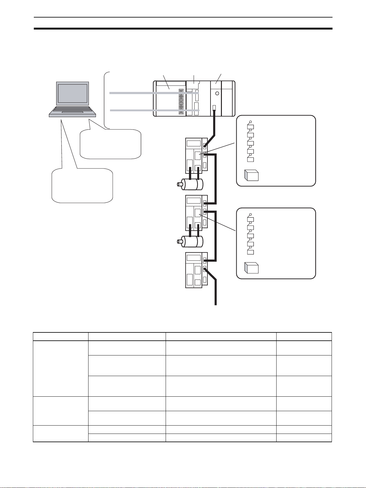
1-1 What is CX-Motion-NCF?
What is CX-MotionNCF?
Features
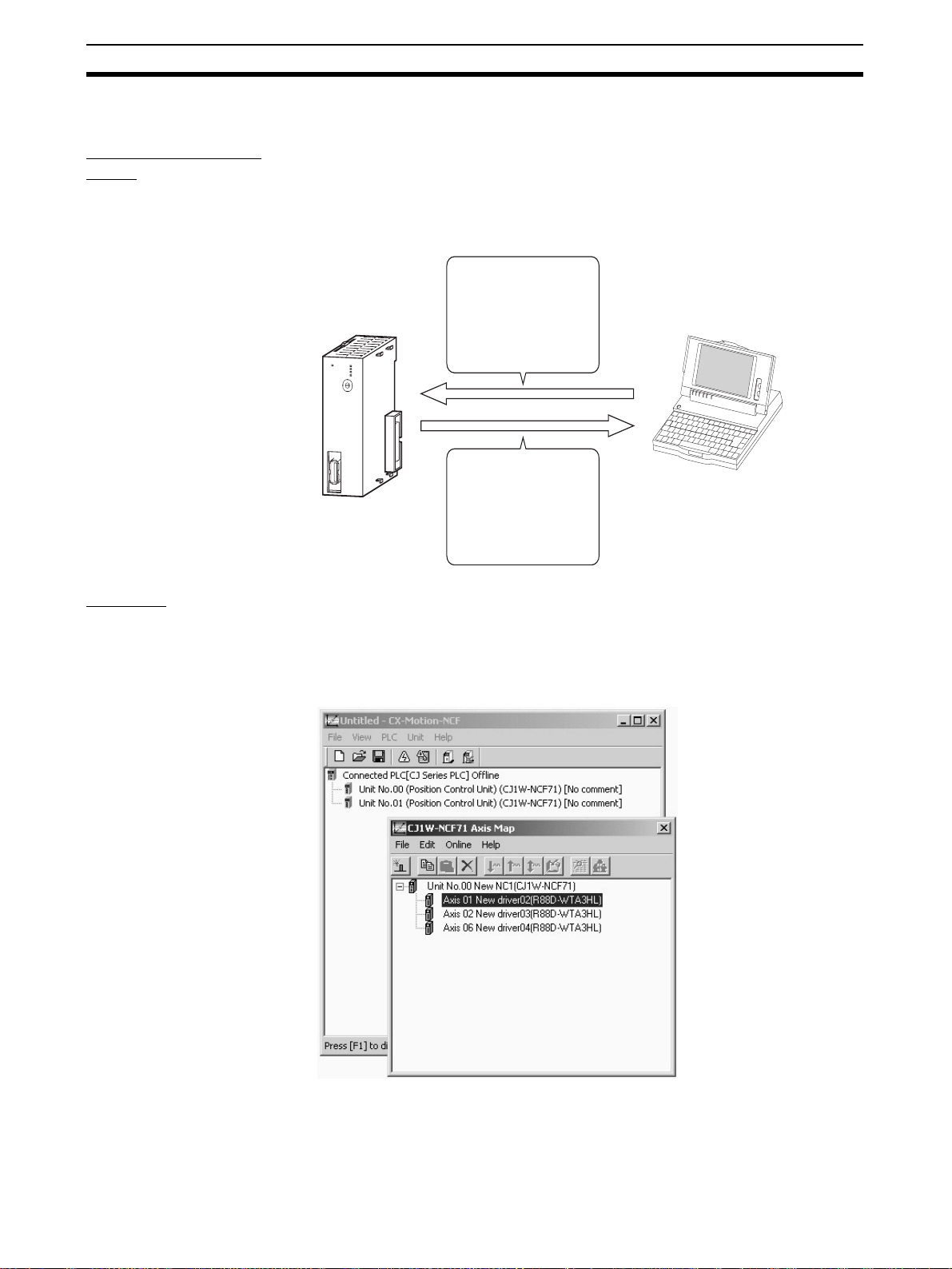
CX-Motion-NCF is a software package that helps to set, transfer, save, and
print various data used for the CJ1W-NCF71 Position Control Unit (also
referred to as PCU or NC Unit) and to monitor the operation status of the Position Control Unit.
CX-Motion-NCF runs on Windows98, Me, NT 4.0, 2000, or XP.
Computer with
Windows
operating system
CJ1W-NCF71
NCF71
MLK
R
UN
ERC
ER
H
ERM
D
C
E
B
U
N
IT
F
A
0
9
1
8
N
o
.
2
7
3
6
4
5
M
L
K
Parameters used with
the NC Unit are set and
transferred.
The NC Unit's operating
status (e.g., present
position, I/O status, and
error display) is
monitored.
Data Management and
Editing in Project Units
The CX-Motion-NCF manages data for several Position Control Units as one
project. Position Control Units are displayed under a PLC and several Servo
Drivers (up to 16 axes) are displayed under a Position Control Unit, both in
tree format.
Communications with
Position Control Units via
Networks
2
CX-Motion-NCF communicates with Position Control Units using CX-Server.
Host Link (SYSMAC WAY) or peripheral bus (Toolbus) can be used to perform
online operations (transferring, comparing, and monitoring parameter data)
with the Position Control Unit on the PLC.
What is CX-Motion-NCF? Section 1-1
Editing Servo Parameters Parameters of Servo Drivers connected to a Position Control Unit can be
edited using CX-Motion-NCF.
Displaying Error
Information
Applicable
Computers
Information on the error that is currently occurring on a Position Control Unit
or the error log can be displayed.
CX-Motion-NCF can be used on computers that satisfy the following conditions.
The following conditions apply when installing the CX-Motion-NCF as an individual application. Different conditions will apply when installing the CXMotion-NCF as one of the features of the CX-One FA Integrated Tool Package. Refer to the CX-One Setup Manual (W444) for the specific conditions.
OS
Windows 98 or Windows
Item
Computer IBM PC/AT or compatible IBM PC/AT or compatible IBM PC/AT or compatible
CPU Pentium Class 133 MHz or
RAM memory 64 Mb min. 96 Mb min. 128 Mb min.
Hard disk drive 100 Mb min. of free space 100 Mb min. of free space 100 Mb min. of free space
Monitor 800 × 600 SVGA or higher 800 × 600 SVGA or higher 800 × 600 SVGA or higher
CD-ROM drive 1 min. 1 min. 1 min.
Communications port 1 RS-232C port min. 1 RS-232C port min. 1 RS-232C port min.
NT4.0 Service Pack 6
higher
Windows Me or Windows
2000 Service Pack 3 or
higher
Pentium Class 150 MHz or
higher
Windows XP
Pentium Class 300 MHz or
higher
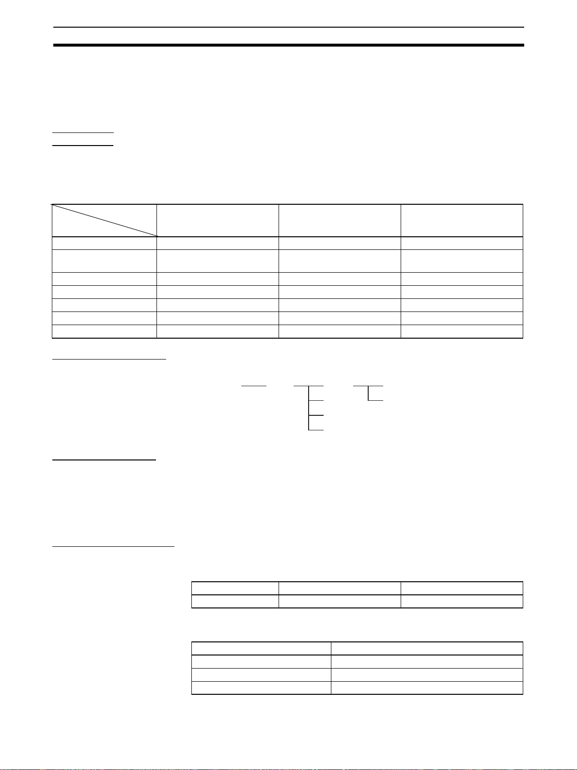
CX-Motion-NCF Data CX-Motion-NCF is used to create project files with the configuration shown
below. The file extension for project files is .mnf.
Project File
(
*.mnf)
PLC
NC
NC
NC
NC
Unit Parameter
Servo Parameter
Software Structure CX-Motion-NCF exchanges data (online communications) with Position Con-
trol Units via CX-Server. In order to execute functions online, CX-Server must
be installed on the same computer that has CX-Motion-NCF installed.
CX-Server is bundled on the setup disk of CX-Motion-NCF.
Either the Toolbus or SYSMAC WAY (Host Link) can be selected for the network type.
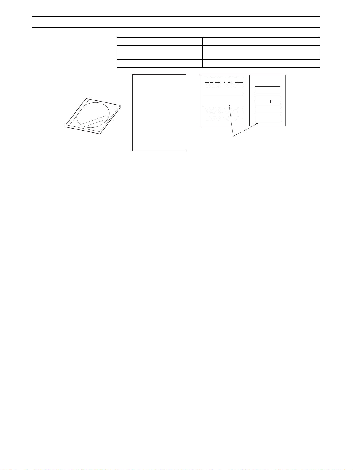
Checking the Package After purchase, confirm that the contents of the package are as described
below.
CX-Motion-NCF Model
Number
CX-Motion-NCF Package The CX-Motion-NCF software package consists of the following items. Con-
Product name Model number Setup disk
CX-Motion-NCF Model WS02-MNTC1 CD-ROM
firm that accessories are provided.
Item No. of items
Setup Disk (CD-ROM) 1
CX-Motion-NCF Operation Manual PDF manual on CD-ROM
Product Guide 1
3
What is CX-Motion-NCF? Section 1-1
Item No. of items
Software Licence Agreement/User
Registration Card
Address label 1
Product Guide
Note Software Licence Agreement/User Registration Card has the licence number
that is required to install CX-Motion-NCF. Please keep it in a safe place and
do not lose it.
2
The model, version, and license
No. is shown in the Software
License Agreement.
4
System Configuration Section 1-2
1-2 System Configuration
The system configuration for Position Control Units is shown below.
CX-Motion-NCF
Editing/Transferring
parameters
Monitor
File management, etc.
CX-Programmer
Creating/Transferring
ladder program
Monitor
File management, etc.
Toolbus/
Host Link
Power
Supply Unit
Servo Driver
Servomotor
Servo Driver
Servomotor
Servo Driver
CJ Series
CPU Unit
NC Unit
(CJ1W-NCF71)
External input
Forward rotation limit input signal
Reverse rotation limit input signal
Origin input signal
Origin proximity input signal
Interrupt input signal
:
24-V DC power supply for
interface
External input
Forward rotation limit input signal
Reverse rotation limit input signal
Origin input signal
Origin proximity input signal
Interrupt input signal
24-V DC power supply for
interface
MECHATROLINK-II
(16 axes max.)
1-3 Function List
Group Function Details Reference
Editing projects Create project Used to create project files (*.mnf) 4-1 Creating a New
Project
Create Position Control Unit Used to add Position Control Unit data to a
project.
Create Servo Driver Used to add Servo Driver data to a project. 4-3 Adding and
Editing data Edit Unit Parameters Used to edit Unit Parameters. 5-1 Editing Unit
Edit Servo Parameters Used to edit Servo Parameters. 5-2 Editing Servo
Saving and reading
project files
Save project Used to save data as a project file (*.mnf). 6-1 Saving Project
Read project Used to read a project file (*.mnf). 6-2 Reading Project
4-2 Adding and
Deleting Position
Control Units
Deleting Servo Drivers
Parameters
Parameters
5

Function List Section 1-3
Group Function Details Reference
Importing and
exporting data
Printing Print Used to print the data displayed on the
Online Initial setting Used to setup CPU Unit or Position Control
JOG JOG Used to execute JOG operation. 9-1 Test Run
Error Error log Used to display the error log. 10-1 Error Log
Import Used to import Unit/Servo Parameters. 6-3 Import
Export Used to export Unit/Servo Parameters. 6-4 Export
screen.
Unit.
Communications setting Used to make communications settings. 7-2 Setting/Chang-
Download
Upload
Compare
Write to flash memory Used to save the downloaded Unit Parame-
Monitor Used to display the Unit's status, axis
Device information Used to read the Unit’s model, system soft-
Error information Used to display error code, error name. 10-2 Error Code
Used to download, compare, or upload Unit
or Servo Parameters.
ters.
present position, axis status, and error information.
ware version, and attached information.
6-5 Print
7-1 Initial Setting for
Connecting Online
ing Communications
Specific
7-3 Downloading
Data
7-4 Uploading Data
7-5 Comparing Data
7-6 Writing to Flash
Memory
8-1 Unit Monitor
8-2 Axis Monitor
---
6
Operation Procedure Section 1-4
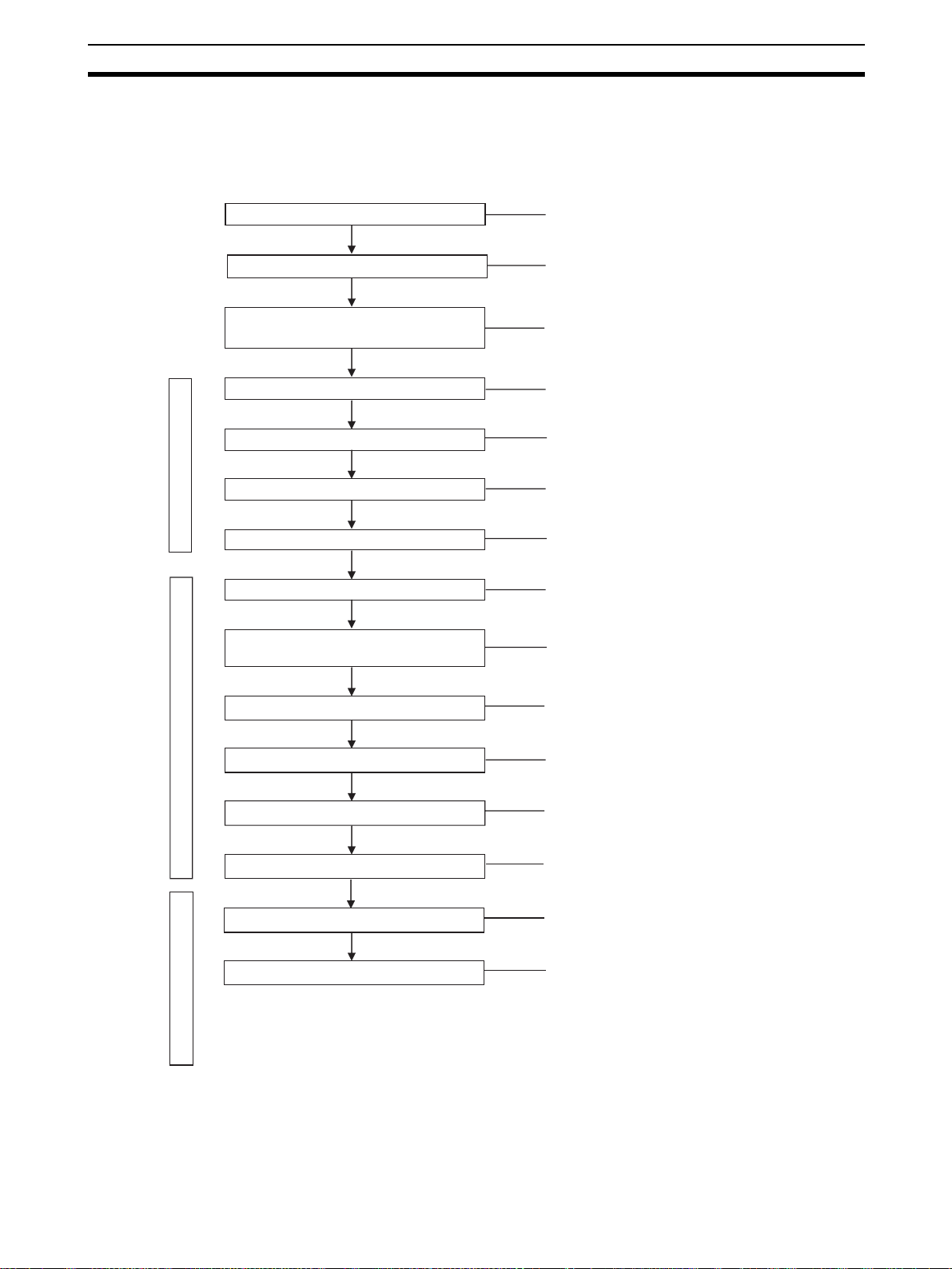
1-4 Operation Procedure
The outline of the procedures required to install CX-Motion-NCF and CXServer, create various data, transfer it to Position Control Units, and use in
actual operations is shown below.
Installing CX-Server
Installing CX-Motion-NCF
Connecting to Built-in RS-232C port on
CPU Unit
CX-Motion-MCF Basic Window
Axis Map Setting Window
Starting CX-Motion-NCF
Creating a New Project
Adding NC Unit to Project
Starting Axis Map Setting Window
Adding Servo Driver to NC Unit
Editing/Transferring Unit
Parameters/Servo Parameters
Refer to SECTION 2-1
Refer to SECTION 2-1
Refer to SECTION 2-2
Refer to SECTION 3-2
Refer to SECTION 4-1
Refer to SECTION 4-2
Refer to SECTION 3-2
Refer to SECTION 4-3
Refer to SECTION 5-1, 5-2, 7-3, and 7-4
Writing to Flash Memory
NC Unit Positioning Operation
Monitoring
Quitting Axis Map Setting Window
CX-Motion-NCF Basic Window
Saving Project
Quitting CX-Motion-NCF
Refer to SECTION 7-6
Refer to the Position Control
Unit's operation manual.
Refer to SECTION 8
Refer to SECTION 3-2
Refer to SECTION 6-1
Refer to SECTION 3-2
7

Operation Procedure Section 1-4
8

SECTION 2
This section provides information on installing CX-Motion-NCF and CX-Server, and connecting to the PLC.
2-1 Installing and Uninstalling the Software. . . . . . . . . . . . . . . . . . . . . . . . . . . . . 10
2-1-1 Software That Must Be Installed . . . . . . . . . . . . . . . . . . . . . . . . . . . 10
2-1-2 Preparations for Installation . . . . . . . . . . . . . . . . . . . . . . . . . . . . . . . 10
2-1-3 Precautions for Installation . . . . . . . . . . . . . . . . . . . . . . . . . . . . . . . . 11
2-1-4 Installing the CX-Motion-NCF. . . . . . . . . . . . . . . . . . . . . . . . . . . . . 12
2-1-5 Uninstalling the CX-Motion-NCF . . . . . . . . . . . . . . . . . . . . . . . . . . 16
2-1-6 Uninstalling the CX-Server . . . . . . . . . . . . . . . . . . . . . . . . . . . . . . . 17
2-2 Connecting to PLC . . . . . . . . . . . . . . . . . . . . . . . . . . . . . . . . . . . . . . . . . . . . . 19
Setup
9

Installing and Uninstalling the Software Section 2-1
2-1 Installing and Uninstalling the Software
2-1-1 Software That Must Be Installed
The following software must be installed on the same computer to use the CXMotion-NCF.
1,2,3... 1. CX-Motion-NCF
2. CX-Server (the communications driver)
Types of CX-Motion-NCF The CX-Motion-NCF is available both on an independent CD-ROM and on the
CX-One FA Integrated Tool Package. The contents of the CX-Motion-NCF are
the same in either case.
The installation procedure for the independent CD-ROM is provided here.
Refer to the CX-One Setup Manual (W444, provided with the CX-One) for the
installation procedure for the CX-One.
Cat. No. Model Manual name Contents
W444 CXONE-AL@@-E CX-One Setup Man-
ual
2-1-2 Preparations for Installation
An overview of the CXOne FA Integrated Tool
Package and the CX-One
installation procedure
Note If the CX-Motion-NCF was previously installed from the CX-One and it's nec-
essary to install it from the individual CX-Motion-NCF CD-ROM, always uninstall the CX-Motion-NCF using the following procedure before installing it from
its individual CD-ROM. The CX-Motion-NCF will not operate properly if it is
installed without first uninstalling it.
a) Insert the CX-One installation disk 1 into the CD-ROM drive.
b) Select the Modify Option to enable modifying the Support Software
that is installed.
c) In the Select Features Dialog Box, clear the selection of only the CX-
Motion-NCF. Do not change any other selections.
d) Continue by following the instructions in the dialog boxes to modify the
installation and uninstall CX-Motion-NCF.
e) Once the CX-Motion-NCF uninstallation process has been completed,
place the individual CD-ROM disk for the CX-Motion-NCF into the CDROM drive and install the CX-Motion-NCF. (See note.)
Note If the version of the CX-Server bundled on the individual CX-Motion-
NCF CD-ROM is lower than the version of the CX-Server bundled
with the CX-One, install only the CX-Motion-NCF and NOT the CXServer. (A message will be displayed if the version is lower.) If a version of CX-Server that is lower than the version with the CX-One is
installed, the CX-One will not operate properly.
10
Installing and Uninstalling the Software Section 2-1
Uninstalling the Previous
Version of CX-Motion-NCF
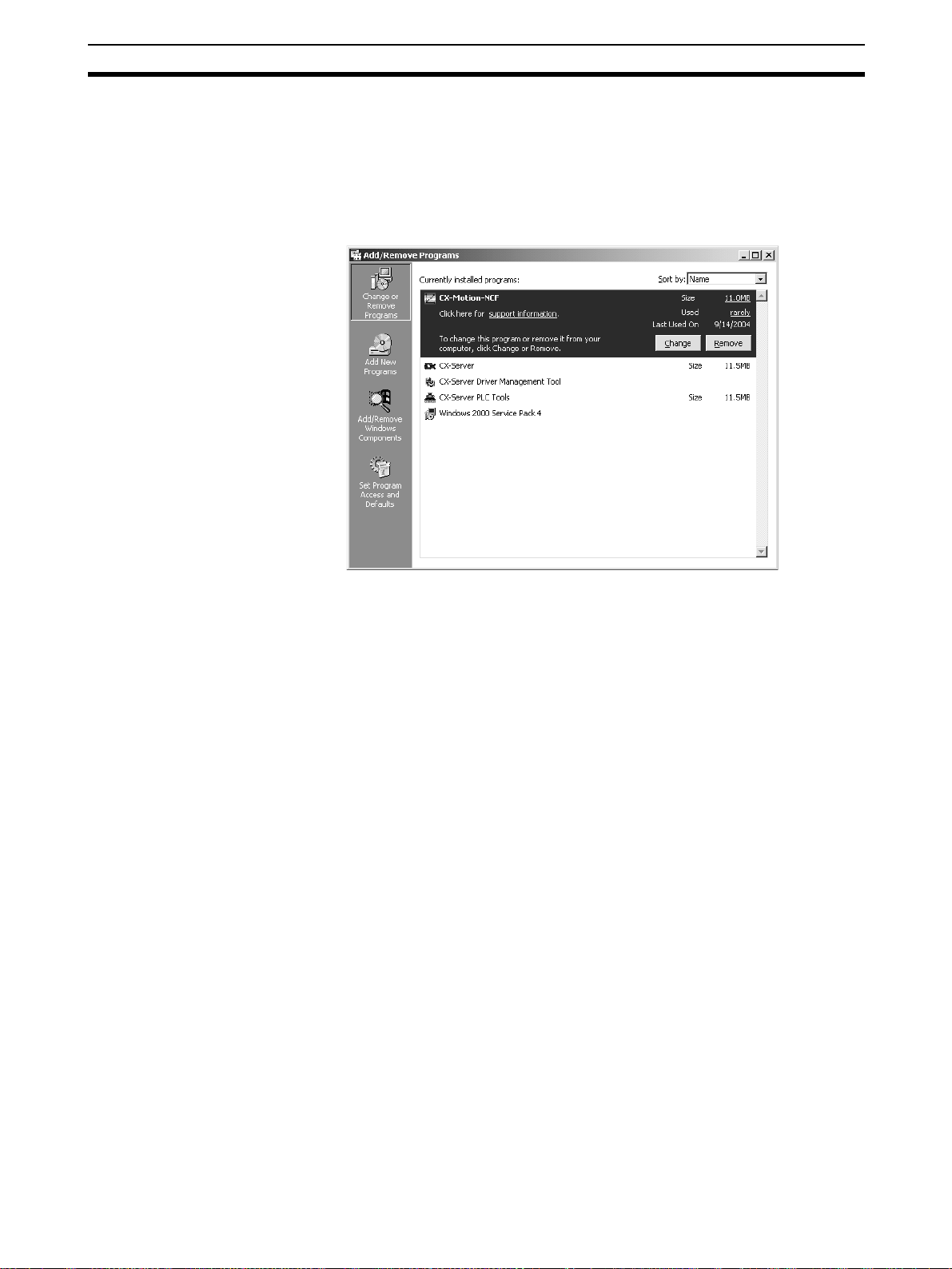
1,2,3... 1. Start Add/Remove Programs from the control panel.
Always uninstall the previous version of the CX-Motion-NCF before installing
the new version.
2. Select CX-Motion-NCF from the dialog box.
3. Click the Change/Remove Button. The CX-Motion-NCF will be uninstalled.
Note The Installer manages the version and driver for the CX-Server. If the CX-
Server installed on the computer is old, the Installer will automatically update
the CX-Server. If the CX-Server Driver Management Tool or the CX-Server is
uninstalled from the control panel, it may no longer be possible to use certain
Units. Do not uninstall the CX-Server Driver Management Tool or the CXServer from the control panel.
2-1-3 Precautions for Installation
This section describes the procedures involved in the installation of CXMotion-NCF on a standard workstation running Microsoft Windows 98, Me,
NT4.0, 2000, or XP.
• Close all programs running on Windows before starting the installation
procedure.
• Do not stop the setup process in the middle. Copied files may remain in
the installation directory.
• Do not turn OFF or reset the computer in the middle of the installation
process. Computer data may become corrupted.
• On Windows NT 4.0, 2000, or XP, the administrator or a user with administrator rights must perform the installation. Other users will not have sufficient write permissions and access errors will occur.
• With Windows 2000, always use service pack 3 or later. With Windows
NT 4.0, always use service pack 6a. The service pack can be confirmed
by selecting Start - Settings - Control Panel - System. The service pack
will be displayed under System on the General Tab Page of the System
Properties Dialog Box. If a service pack is not displayed, no service pack
has been installed. Refer to Microsoft’s website for service pack installation methods.
11
Installing and Uninstalling the Software Section 2-1
• It may be necessary to restart Windows after finishing the installation. If
required, restart Windows according to the messages displayed by the
Installer.
Note Internet Explorer version 5.0 or higher must be installed in advance to use the
CX-Server Installer. Install Internet Explorer version 5.0 in advance if it is not
already installed.
2-1-4 Installing the CX-Motion-NCF
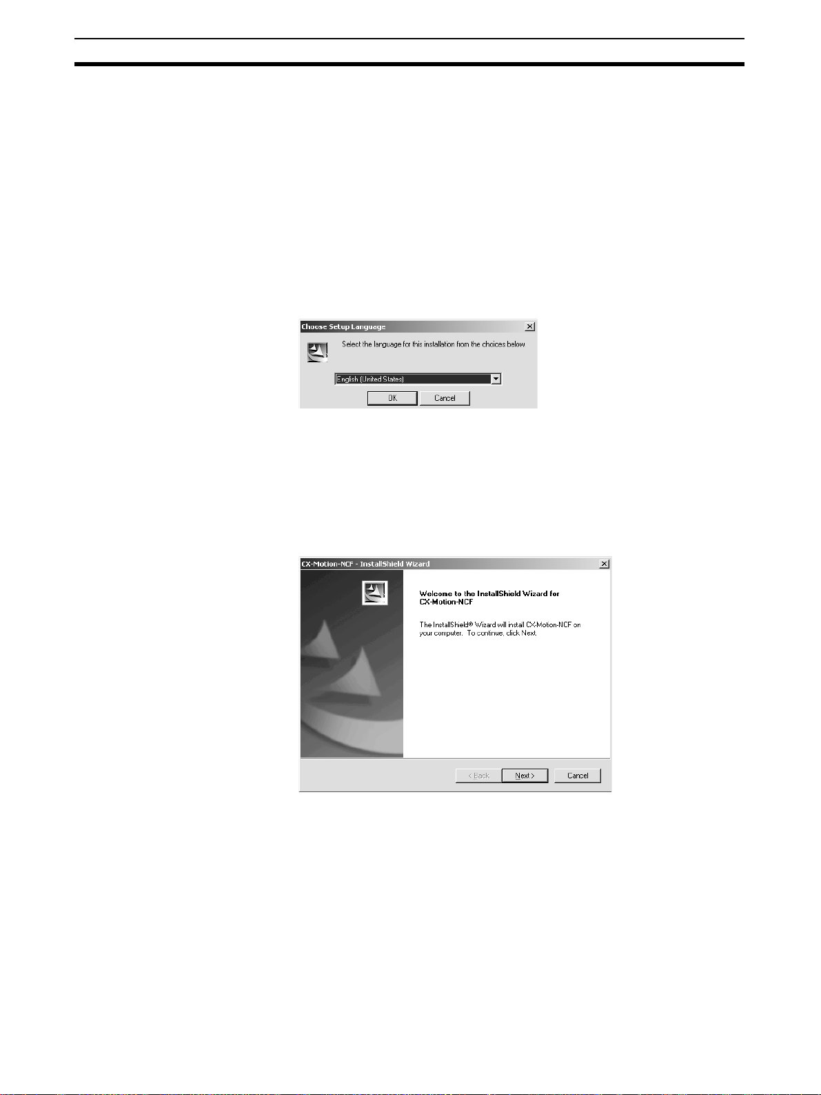
1,2,3... 1. Insert the CX-Motion-NCF installation disk (CD-ROM) into the CD-ROM
drive.
2. The setup program will start automatically and the Choose Setup Lan-
guage Dialog Box will be displayed.
The language of the operating system running on the computer will be selected automatically.
If the above dialog box is not displayed, double-click the CD-ROM drive
from the Explorer to display it.
Select the language to be installed and click the OK button.
3. A splash window for the CX-Motion-NCF will be displayed, followed by the
Setup Wizard.
12
Click the Next Button.
Installing and Uninstalling the Software Section 2-1
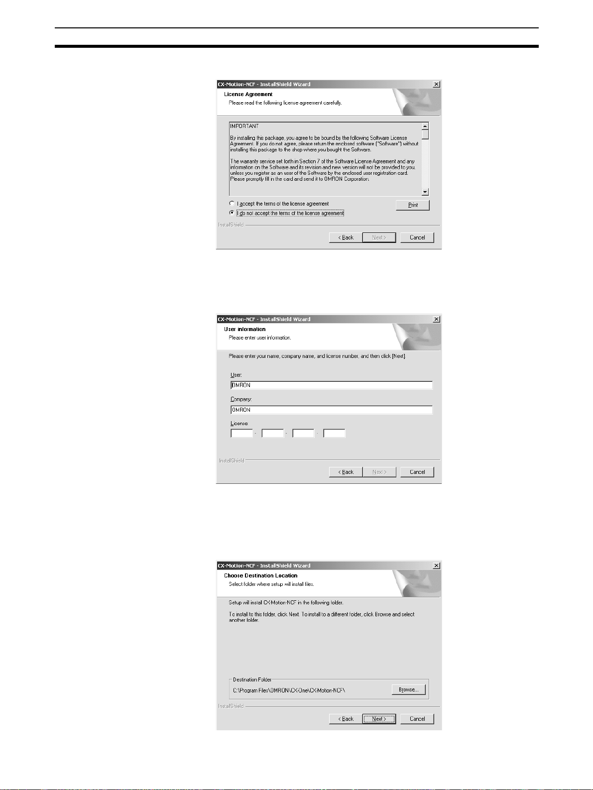
4. The License Agreement Dialog Box will be displayed.
Read the license agreement completely and if you accept all of the terms,
select the I accept the terms of the license agreement Option and click the
Next Button.
5. The User Information Dialog Box will be displayed.
The default names registered in the computer will be entered for the user
name and company name. Enter the license number and click the Next
Button. The license number is given on the Software License/Registration
Card provided with the product.
6. The Choose Destination Location Dialog Box will be displayed.
13

Installing and Uninstalling the Software Section 2-1
Select the destination location and click the Next Button. By default, the
CX-Motion-NCF will be installed in the following location: C:\Program
Files\OMRON\CX-One\CX-Motion-NCF\.
7. The Setup Type Dialog Box will be displayed.
Select the Complete option and click the Next Button.
8. The Select Program Folder Dialog Box will be displayed.
14
Specify the location to add a shortcut in the program folder of the Windows
Start Menu and click the Next Button.
9. The Ready to Install the Program Dialog Box will be displayed.

Installing and Uninstalling the Software Section 2-1
Click the Install Button.
The Installer will start the installation.
To check the installation settings, click the Back Button.
To cancel installation, click the Cancel Button.
10. If the CX-Server is already installed on the computer, the Installer will automatically check the CX-Server version and driver and update them as required. Depending on the version of CX-Server that was already installed,
a confirmation dialog box may be displayed.
11. The following dialog box will be displayed when the Installer completes the
installation. Click the Finish Button.
The following dialog box will be displayed if restarting the computer is required.
Select to restart the computer
immediately (default).
Select to restart the computer
manually sometime later.
Select the desired option and click the Finish Button. If the Yes, I want to
restart my computer now Option was selected, the computer will be restarted.
12. The Readme.txt file will be displayed after the computer is restarted.
Note Always read the Readme.txt file before using the CX-Motion-NCF.
15

Installing and Uninstalling the Software Section 2-1
13. The Online Registration Dialog Box will be displayed when the Readme.txt
file is closed.
A wizard will be started and will connect to the OMRON CX-One Web if the
Register Button is clicked. (See notes.)
Note (a) If the Exit Button is clicked to cancel registration, the Online Reg-
istration Dialog Box will be displayed every time the CX-One Configuration Tool is started.
(b) Online installation will not be possible if the computer is not con-
nected to the Internet. Enter the required information on the registration card and mail it in.
This completes installation of the CX-Motion-NCF.
2-1-5 Uninstalling the CX-Motion-NCF
Use the following procedure to delete the CX-Motion-NCF from the computer.
1,2,3... 1. Select Start - Settings - Control Panel - Add/Remove Programs.
The Add/Remove Programs Dialog box will be displayed.
2. Select CX-Motion-NCF from the dialog box.
3. Click the Change/Remove Button.
4. If deleting the CX-Motion-NCF completely is selected, the following dialog
box will be displayed. Click the Yes Button to start the Uninstaller that will
delete the CX-Motion-NCF.
16

Installing and Uninstalling the Software Section 2-1
5. When the uninstallation has been completed, the following dialog box will
be displayed.
2-1-6 Uninstalling the CX-Server
Note (1) The Installer manages the version and driver for the CX-Server. If the CX-
Server installed on the computer is old, the Installer will automatically update the CX-Server. If the CX-Server Driver Management Tool or the CXServer is uninstalled from the control panel, it may no longer be possible
to use certain Units. Do not uninstall the CX-Server Driver Management
Tool or the CX-Server from the control panel.
(2) Do not uninstall the CX-Server if there are other programs on the com-
puter that use it as the communications driver, e.g., the CX-Motion. If the
CX-Server is uninstalled, it will no longer be possible to use these other
programs.
(3) Do not uninstall the CX-Server while other programs that use it as the
communications driver are running on the computer, e.g., the CX-Motion.
The CX-Server may not uninstall properly if other programs are using it.
(4) Always uninstall the CX-Server Driver Management Tool before uninstall-
ing the CX-Server. If the CX-Server is uninstalled first, it may no longer
be possible to uninstall the CX-Server Driver Management Tool properly.
17

Installing and Uninstalling the Software Section 2-1
1,2,3... 1. Select Start - Settings - Control Panel - Add/Remove Programs.
The Add/Remove Programs Dialog box will be displayed.
2. Select CX-Server Driver Management Tool from the dialog box.
3. Click the Change/Remove Button.
4. A confirmation dialog box will be displayed. Click the Yes Button.
The CX-Server Driver Management Tool will be uninstalled.
5. When the uninstallation has been completed, the following dialog box will
be displayed. Click the Finish Button. The Add/Remove Programs Dialog
Box will be displayed again.
6. In the same way, select CX-Server from the Add/Remove Programs Dialog
Box, click the Change/Remove Button, and uninstall the CX-Server following the messages that appear on the screen.
7. Restart the computer when all programs have been uninstalled.
18

Connecting to PLC Section 2-2
t
2-2 Connecting to PLC
To transfer the project data that was created using CX-Motion-NCF to the
Position Control Unit, the personal computer and PLC (CPU Unit) have to be
physically connected with a cable and also connected online.
Connection Format Using either the Host Link (SYSMAC WAY) or Toolbus, connect the personal
computer to the peripheral port or RS-232C port on the PLC.
Personal
Connecting to Peripheral Port Connecting to RS-232C Port
computer
IBM PC/AT
or compatible
P
C
9
8
0
1
B
X
N
E
C
CS1W-CN118
CS1W-CN226
CS1W-CN626
9-pin
male
9-pin
female
Peripheral port
(10-pin female)
CS1W-CN118 (0.1 m) (See note.)
CS1W-CN226 (2.0 m)
CS1W-CN626 (6.0 m)
(See note.)
9-pin
10-pin
female
9-pin
male
PC
-980
1
B
X
NE
C
9-pin
female
XW2Z-200S-CV / 200S-V (2.0 m)
XW2Z-500S-CV / 500S-V (5.0 m)
XW2Z-200S-CV / -200S-V
XW2Z-500S-CV / -500S-V
9-pin
male
RS-232C port
(9-pin female)
9-pin
female
Note The cable model CS1W-CN118 is used as a relay cable to connect the per-
sonal computer to the CPU Unit's peripheral port using the RS-232C cable
(model XW2Z-@@@@-@@) as shown below.
Peripheral Por
P
C
-9
8
0
1
BX
N
EC
RS-232C Cable
CS1W-CN118
9-pin
male
Note Two network types (serial communications mode), SYSMAC WAY and Tool-
bus, are supported when connecting CX-Motion-NCF to the PLC. The characteristics of the network types are as shown below.
Network type Characteristics
Toolbus Faster communications. If possible, use this network type.
• For CS/CJ Series, the baud rate on the peripherals can be
detected automatically, and be connected.
• Only 1 on 1 connection possible.
• For CX-Motion-NCF, it can also be connected to a modem.
SYSMAC WAY
(Host Link)
Used for communications with general host computers.
• Slower than Toolbus.
• Not only 1 on 1 connection, but also 1-many connection possible.
• Connecting to a modem and optical adaptor possible.
19

Connecting to PLC Section 2-2
Connection Method Use one of the following method to connect the personal computer (CX-
Motion-NCF) and PLC (CPU Unit). It is also possible to connect the personal
computer to the port on the CJ Series Serial Communications Unit. In that
case, the only network type that can be used is Host Link.
Connecting to Peripheral Port Connecting to RS-232C Port
IBM PC/AT or compatible IBM PC/AT or compatible
9-pin connector
CS1W-CN118 (0.1 m)
CS1W-CN226 (2.0 m)
CS1W-CN626 (6.0 m)
Connection Cables
Unit Port on Unit Computer Port on
CPU Unit Built-in
peripheral
port
Built-in RS232C port
(D-SUB, 9pin, female)
Serial
Communications
RS-232C port
(D-SUB, 9pin, female)
Unit
IBM PC/AT
compatible
IBM PC/AT
compatible
IBM PC/AT
compatible
D-SUB, 9pin, male
D-SUB, 9pin, male
D-SUB, 9pin, male
computer
9-pin connector
Peripheral port
on CPU Unit
Network type
XW2Z-200S-CV (2.0 m)
9-pin connector
XW2Z-500S-CV (5.0 m)
Model number Length Remarks
Built-in RS-232C port
on CPU Unit or Serial
Communications Unit
(serial commu-
nications
mode)
SYSMAC WAY CS1W-CN226 2 m ---
CS1W-CN626 6 m
SYSMAC WAY XW2Z-200S-CV 2 m Uses anti-static
XW2Z-500S-CV 5 m
connector
SYSMAC WAY XW2Z-200S-CV 2 m Uses anti-static
XW2Z-500S-CV 5 m
connector
Note When connecting the connectors of the above cables to the PLC's RS-232C
port, discharge any static build-up (e.g., by touching a grounded metal object)
before touching the connectors. Although XW2Z-@@@S-CV Cables use the
anti-static XM2S-0911-E Connector Hood (thus reducing the possibility of
static build-up), be sure to discharge any static as a safety precaution.
20

This section describes each of the screens and basic operations.
3-1 Screen Name . . . . . . . . . . . . . . . . . . . . . . . . . . . . . . . . . . . . . . . . . . . . . . . . . . 22
3-2 Basic Operation. . . . . . . . . . . . . . . . . . . . . . . . . . . . . . . . . . . . . . . . . . . . . . . . 25
3-2-1 CX-Motion-NCF Basic Operation . . . . . . . . . . . . . . . . . . . . . . . . . . 25
3-2-2 Axis Map Setting Window Basic Operation. . . . . . . . . . . . . . . . . . . 29
3-3 Operations Listed by Purpose . . . . . . . . . . . . . . . . . . . . . . . . . . . . . . . . . . . . . 32
SECTION 3
Basic Operation
21

Screen Name Section 3-1
3-1 Screen Name
The window names for CX-Motion-NCF are shown here.
Basic Window
CX-Motion-NCF Basic Window
Axis Map Setting Window
22

Screen Name Section 3-1
Edit Parameter Window
23
Screen Name Section 3-1
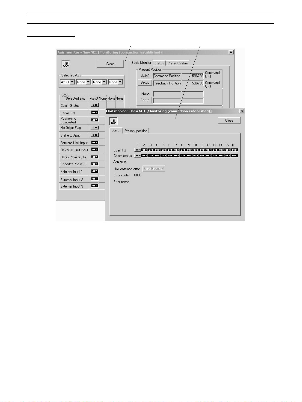
Monitor Window
Axis Monitor Window Unit Monitor Window
24

Basic Operation Section 3-2
3-2 Basic Operation
3-2-1 CX-Motion-NCF Basic Operation
The basic operations of CX-Motion-NCF are explained here.
Starting CX-Motion-NCF
Starting CX-Motion-NCF Using Start Special Application - Start with Settings Inherited from the I/O
Table Window Opened from the CX-Programmer That Was Installed from the CX-One
1,2,3... 1. Right-click a Position Control Unit in the I/O Table Window and select Start
Special Application - Start with Settings Inherited from the pop-up
menu.
2. The CX-Motion-NCF will be started, a new project will be created, and a
Position Control Unit will be added automatically. The Position Control Unit
model will be inherited as shown below
25

Basic Operation Section 3-2
Starting CX-Motion-NCF Using Start Special Application - Start Only from the I/O Table Window
Opened from the CX-Programmer That Was Installed from the CX-One
Right-click a Position Control Unit in the I/O Table Window and select Start
Special Application - Start Only from the pop-up menu. The following win-
dow will be displayed with a new project.
Starting CX-Motion-NCF
from Windows Start Menu
Quitting CX-Motion-NCF
1,2,3... 1. Select File/Exit or click at the top right corner of the window. After ed-
Select Start. Select Programs - OMRON - CX-One - CX-Motion-NCF - CX-
Motion-NCF. The same window as when selecting Start Only will be dis-
played with a new project.
iting a project, if the project has not been saved, the following dialog box
will be displayed.
2. Click the Yes Button to save the changes made. Click the No Button if it is
not necessary to save the changes. Click the Cancel Button to return to
the Basic Window without quitting CX-Motion-NCF.
26

Basic Operation Section 3-2
CX-Motion-NCF Basic
Window
Main Menus
The CX-Motion-NCF Basic Window is shown below.
Main Menu Contents Keyboard
File Used to create or save projects. Alt+F
View Used to display or hide Toolbar or Status Bar. Alt+V
PLC Used to connect to PLC. Alt+P
Unit Used to add or delete Position Control Unit, or to open
Axis Map Setting Window.
Help Used to display help and version information. Also used
to register online.
shortcut
Alt+U
Alt+H
Main Menu Items The names and functions for all of the menus are given in the table below.
When an item is selected, the dialog box for that function is displayed. follow
the instructions in the dialog box.
Main menu Item Contents Keyboard
shortcut
File New Creates a new project file. Ctrl+N
Open... Opens an existing project file. Ctrl+O
Save Saves the active project (over-
Save As Saves the active project with a
Exit Quits CX-Motion-NCF. ---
View Toolbar Displays/hides toolbar. ---
Status Bar Displays/hides status bar. ---
PLC Online Connects to PLC. ---
Communication Settings
writes the previous data).
new name.
Sets communications for online
connection.
Ctrl+S
---
---
27
Basic Operation Section 3-2
(1) (2) (3) (4) (5) (6) (7)
Main menu Item Contents Keyboard
Unit Edit Parameters Opens Axis Map Setting Window. ---
Change Unit No. Changes Unit No. of PCU. ---
Edit Comment Edits comment. ---
Add Adds PCU to a project. ---
Delete Deletes PCU from a project. ---
Help Help Index Displays the table of contents for
Online Registration Connects to the Omron CX-One
About CX-Motion
NCF...
help.
Website for online user registration.
Displays the version information
for CX-Motion-NCF.
shortcut
F1
---
---
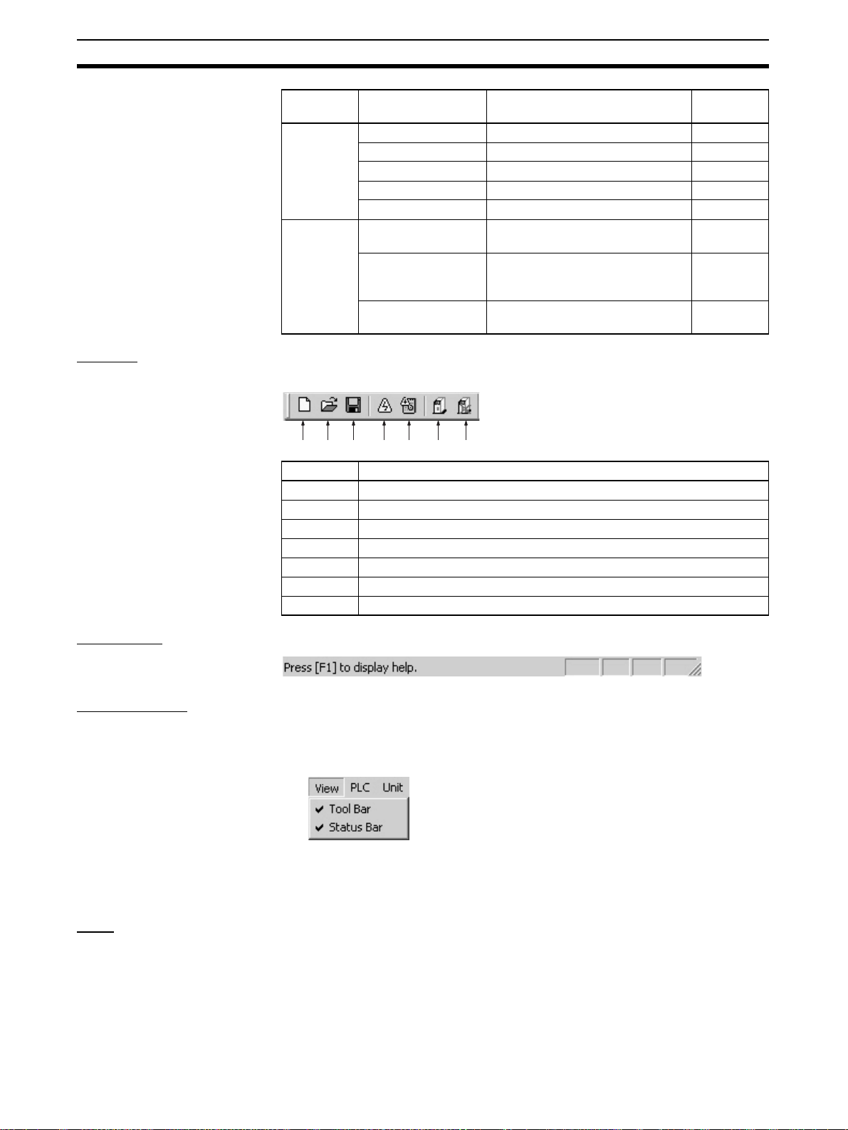
Toolbar Functions can be executed directly by clicking on the appropriate icon on the
toolbar. The functions that can be executed from the toolbar are given below.
Number Function
(1) Creates a new project.
(2) Opens an existing project.
(3) Saves the active project.
(4) Connects online to PLC.
(5) Displays communications settings window to connect to PLC.
(6) Adds a new Position Control Unit.
(7) Deletes a Position Control Unit.
Status Bar The following information is displayed on the status bar.
View Settings The view settings can be used to display or hide the toolbar or status bar.
Display/Hide Settings
1,2,3... 1. Click View.
2. If a check appears next to Toolbar or Status Bar, the corresponding item is
displayed. To hide any of these, click Toolbar or Status Bar to remove the
check.
Help
Displaying the Help Contents
1,2,3... 1. Click Help/Help Index. The table of contents for help will be displayed.
2. Click an item to display information related to that item.
28

Basic Operation Section 3-2
Displaying CX-MotionNCF and CX-Server
Version Information
Click Help/About CX-Motion-NCF. The CX-Motion-NCF and CX-Server ver-
sion information will be displayed.
3-2-2 Axis Map Setting Window Basic Operation
The basic operations of the Axis Map Setting Window used to make the Position Control Unit settings are explained here.
Starting the Axis Map
Setting Window
Click Unit/Edit Parameters, or double-click on a Position Control Unit after
selecting one on the CX-Motion-NCF Basic Window.
Quitting Axis Map
Setting Window
Axis Map Setting
Window
Main Menus
Click File/Exit, or click at the right top corner of the Axis Map Setting Window.
The Axis Map Setting Window is shown below.
Main menu Contents Keyboard
File Used, for example, to import or export. Alt+F
Edit Used, for example, to add Servo Drivers or edit parame-
ters.
Online Used, for example, to transfer parameters or monitor
PCUs or axes.
Help Used to display help and version information. Alt+H
shortcut
Alt+E
Alt+L
29

Basic Operation Section 3-2
Main Menu Items The names and functions for all of the menus are given below. When an item
is selected, the dialog box for that function is displayed. Follow the instructions
in the dialog box.
Main menu Item Contents Keyboard
File Import Imports entire PCU project files
Export Exports entire PCU project files
Properties When a Servo Driver item has
Print Prints out Unit Parameters or
Close Closes Axis Map Setting Win-
Edit New Driver Displays the New Driver Dialog. ---
Edit Parameters
Copy Copies an axis. Ctrl+C
Paste Pastes an axis. Ctrl+V
Delete Deletes the selected Servo
Online Download to NC Unit Executes batch download. Dis-
Upload from NC Unit Executes batch upload. Dis-
Compare Executes batch compare. Dis-
Write Flash Memory Writes data to flash memory. ---
Unit Monitor Starts Unit Monitor. ---
Axis Monitor Starts Axis Monitor. ---
Test Run Displays the Test Run Window.
Error Log Displays error log. ---
Device Information Displays device information. ---
Help Help Displays help. F1
About Displays the version information
NC Unit Edits Unit Parameters. ---
Axis Edits Servo Parameters. ---
or Servo Parameters. The file is
to be in CSV format.
or Servo Parameters. The file is
to be in CSV format
been selected, displays the
Servo Driver Properties Window. Invalid when no Servo
Driver item has been selected.
Servo Parameters.
dow.
Closes all the active Edit Parameters and Monitor Windows.
Driver.
plays the Batch Download Dialog.
plays the Batch Upload Dialog.
plays the Batch Compare Dialog.
Connection status, Servo Lock/
Unlock, JOG, etc. can be controlled.
for CX-Motion-NCF and Driver
database.
shortcut
---
---
---
Ctrl+P
---
DEL
---
---
---
---
---
Toolbar Functions can be executed directly by clicking on the appropriate icon on the
toolbar. The functions that can be executed from the toolbar are given below.
(1) (2) (3) (4) (5) (6) (7)
(8) (9) (10)
30

Basic Operation Section 3-2
Number Function
(1) Adds a new driver.
(2) Copy
(3) Paste
(4) Remove
(5) Download to Position Control Unit
(6) Upload from Position Control Unit
(7) Compare
(8) Writes data to flash memory.
(9) Unit Monitor
(10) Axis Monitor
Help
Displaying the Help Contents
1,2,3... 1. Click Help/Help. The table of contents for help will be displayed.
2. Click an item to display information related to that item.
Displaying CX-MotionNCF and Driver Database
Version Information
Click Help/About. The CX-Motion-NCF and Driver database version information will be displayed.
31

Operations Listed by Purpose Section 3-3
3-3 Operations Listed by Purpose
Operations Listed by Purpose
Function (Purpose) Operation Keyboard
Project
Starting CX-Motion-NCF Select Start/Programs/OMRON/CX-Motion-NCF
and click CX-Motion-NCF.
Creating a new project Select File/New on CX-Motion-NCF Basic Window. Ctrl+N 36
shortcut
--- --- 25
Toolbar
icon
Page
Opening a project Select File/Open on CX-Motion-NCF Basic Win-
dow.
Saving (overwriting) Select File/Save on CX-Motion-NCF Basic Win-
dow.
Saving with a different
name
Quitting CX-Motion-NCF Select File/Exit on CX-Motion-NCF Basic Window. --- --- 26
Adding a Position Control Unit
Importing Parameters Select a Position Control Unit on Axis Map Setting
Exporting All the Parameters
Exporting Servo Parameters
Displaying Servo Driver
Properties
Opening Axis Map Setting Window
Closing Axis Map Setting
Window
Adding a Servo Driver On Axis Map Setting Window, click Edit/New
Deleting a Servo Driver Select a Servo Driver on Axis Map Setting Window.
Printing Select File/Print on Axis Map Setting Window. Ctrl+P --- 54
Editing data
Editing Unit Parameters Select Edit/Edit Parameters/NC Unit, or select
Editing Servo Parameters Select Edit/Edit Parameters/Axis**, or select and
Jumping between windows
Select File/Save As on CX-Motion-NCF Basic
Window.
Select Unit/Add on CX-Motion-NCF Basic Window.
Window. Click File/Import, or right-click and click
Import from the pop-up menu.
Select a Position Control Unit on Axis Map Setting
Window. Click File/Export, or right-click and click
Export from the pop-up menu.
Select File/Export, or right-click and select Export
from the pop-up menu after selecting a Servo
Driver on the Axis Map Setting Window.
Select File/Properties, or right-click and select
Properties from the pop-up menu after selecting a
Servo Driver on the Axis Map Setting Window.
Select a Position Control Unit on CX-Motion-NCF
Basic Window. Click Unit/Edit Parameters, or dou-
ble-click the Position Control Unit.
Select File/Close on Axis Map Setting Window. --- --- 29
Driver, or right-click and selecting a Position Control Unit and click New Driver from the pop-up
menu.
Click Edit/Delete, or right-click and click Delete
from the pop-up menu.
and right-click a Position Control Unit and click Edit
Unit Parameters from the pop-up menu on Axis
Map Setting Window.
right-click a Servo Driver and click Edit Servo
Parameters from the pop-up menu on Axis Map
Setting Window.
Jumps around over Axis Map Setting Window, Edit
Parameter Window, and Monitor Window by clicking the mouse.
Ctrl+O 52
Ctrl+S 52
--- --- 52
--- 36
--- --- 53
--- --- 53
--- --- 54
--- --- ---
--- --- 29
--- 37
DEL 39
--- --- 42
--- --- 45
Ctrl+Tab or
Ctrl+Shift+Tab
--- ---
32

Operations Listed by Purpose Section 3-3
Function (Purpose) Operation Keyboard
Online operations
Starting communications
with PLC
Communications setting Select PLC/Communication Settings on CX-
Batch download On Axis Map Setting Window, select Online/
Batch upload On Axis Map Setting Window, select Online/
Batch compare On Axis Map Setting Window, select Online/Com-
Writing to flash memory Select Online/Write Flash Memory on the Axis
Monitoring Position Control Unit
Monitoring axis On Axis Map Setting Window, click Online/Axis
Error log On Axis Map Setting Window, click Online/Error
JOG Select Online/Test Run on the Axis Map Setting
Displaying device information
Display settings
Displaying or hiding Toolbar
Displaying or hiding Status Bar
Displaying help
Displaying Position Control Unit model and version
Displaying help Select Help/Help Index on CX-Motion-NCF Basic
Online registration Select Help/Online Registration in the CX-
Displaying version information
Select PLC/Online on CX-Motion-NCF Basic Window.
Motion-NCF Basic Window.
Download to NC Unit, or select and right-click a
Position Control Unit and click Download to NC
Unit from the pop-up menu.
Upload from NC Unit, or select and right-click a
Position Control Unit and click Upload from NC
Unit from the pop-up menu
pare, or select and right-click a Position Control
Unit and click Compare from the pop-up menu.
Map Setting Window.
On Axis Map Setting Window, click Online/Unit
Monitor, or select and right-click a Position Control
Unit and click Unit Monitor from the pop-up menu.
Monitor, or select and right-click a Position Control
Unit or Servo Driver and click Axis Monitor from
the pop-up menu.
Log, or select and right-click a Position Control Unit
and click Error Log from the pop-up menu.
Window.
Select Online/Device Information from the Axis
Map Setting Window.
Select View/Toolbar on CX-Motion-NCF Basic
Window.
Select View/Status Bar on CX-Motion-NCF Basic
Window.
On Axis Map Setting Window, click Online/Device
Information, or select and right-click a Position
Control Unit and click Device Information from the
pop-up menu.
Window.
Select Help/Help on Axis Map Setting Window. F1 --- 27
Motion-NCF Basic Window.
Select Help/About. --- --- 27
--- 59
--- 58
--- 60
--- 65
--- 69
--- 73
--- 76
--- 79
--- --- 94
--- --- 88
--- --- ---
--- --- 27
--- --- 27
--- --- 27
F1 --- 27
--- --- ---
shortcut
Toolbar
icon
Page
33

Operations Listed by Purpose Section 3-3
34

SECTION 4
Creating Projects
This section provides information on creating projects and adding Position Control Units and Servo Drivers.
4-1 Creating a New Project . . . . . . . . . . . . . . . . . . . . . . . . . . . . . . . . . . . . . . . . . . 36
4-2 Adding and Deleting Position Control Units . . . . . . . . . . . . . . . . . . . . . . . . . 36
4-3 Adding and Deleting Servo Drivers . . . . . . . . . . . . . . . . . . . . . . . . . . . . . . . . 37
35

Creating a New Project Section 4-1
4-1 Creating a New Project
Follow the procedure below to create a new project on the CX-Motion-NCF
Basic Window.
On the CX-Motion-NCF Basic Window, click File/New, press the Ctrl+N keys,
or click in the toolbar.
No new project has to be created when CX-Motion-NCF has just been
started. Operate on the project already being displayed.
4-2 Adding and Deleting Position Control Units
Adding Position
Control Units to
Projects
1,2,3... 1. On the CX-Motion-NCF Basic Window, click Unit/Add, click in the
A Position Control Unit is added to the project.
toolbar, or right click and select Add NC from the pop-up menu.
2. Set the Unit No.
Select a Unit No. for the Position Control Unit as a CPU Bus Unit.
3. Enter comment.
This can be skipped.
36

Adding and Deleting Servo Drivers Section 4-3
4. Click the OK Button.
A Position Control Unit is added to the project.
Deleting Position Control Units
1,2,3... 1. On the CX-Motion-NCF Basic Window, click Unit/Delete, click , or
right-click and select Delete from the pop-up menu after selecting a Position Control Unit to be deleted.
2. The dialog box saying “Delete the selected Unit. Proceed?” will be displayed. Click the OK Button.
4-3 Adding and Deleting Servo Drivers
Adding Servo Driver
to Position Control
Unit
On the CX-Motion-NCF Basic Window, click Unit/Edit Parameters after
selecting a registered Position Control Unit, or double-click a Position Control
Unit to display the Axis Map Setting Window. On the Axis Map Setting Window, add a new Servo Driver.
37

Adding and Deleting Servo Drivers Section 4-3
1,2,3... 1. Click Edit/New Driver, Click in the toolbar, or right-click the Position
Control Unit and select New Driver from the pop-up menu.
2. Enter Driver Name.
Up to 32 one-byte characters can be entered.
3. Select Series.
Click on the drop-down list to select an appropriate series.
Note Select OMRON W Series when using an OMRON R88M-WT@ W-
series Servo Driver with a Yaskawa JUSP-NS115 MECHATROLINK-II Application Module. Select OMRON W Series (Built-in
Communications) when using an OMRON R88M-WN@-ML2 W-se-
ries Servo Driver with Built-in MECHATROLINK-II Communications.
4. Select Driver Model.
Click on the drop-down list to select an appropriate driver model. The driver
models in the list depends on the selected series.
5. Select Version.
Click on the drop-down list to select an appropriate version. The driver versions in the list depends on the selected driver model.
6. Set Axis No.
Click on the drop-down list to select an axis No. The axis Nos. that are already in use will not be displayed.
7. Enter Comment.
Up to 256 one-byte characters can be entered. This can be skipped.
8. Click the OK Button.
A new Servo Driver will be added to the Position Control Unit.
38

Adding and Deleting Servo Drivers Section 4-3
Copying Servo Driver
to Position Control
Unit
Deleting Servo Driver
from Position Control
Unit
On the Axis Map Setting Window, when a Servo Driver that has been registered under a Position Control Unit is copied and pasted on the same Position
Control Unit, a new Servo Driver will be added with the lowest axis number
that is not in use. When a Servo Driver that has been registered under a Position Control Unit is copied and pasted on another Servo Driver (that has to be
registered in advance), the parameters of the copied Servo Driver will be overwritten to the other Servo Driver.
A Servo Driver that has been registered under a Position Control Unit is
deleted.
1,2,3... 1. On the Axis Map Setting Window, after selecting a Servo Driver to be de-
leted, click Edit/Delete, Click in the toolbar, press the Delete key, or
right-click the Servo Driver and select Delete from the pop-up menu.
39

Adding and Deleting Servo Drivers Section 4-3
2. Click the OK Button.
The Servo Driver will be deleted from the Position Control Unit.
40

This section describes the operations used to edit data.
5-1 Editing Unit Parameters . . . . . . . . . . . . . . . . . . . . . . . . . . . . . . . . . . . . . . . . . 42
5-1-1 Editing Memory Area Parameters . . . . . . . . . . . . . . . . . . . . . . . . . . 43
5-1-2 Editing Communications Parameters . . . . . . . . . . . . . . . . . . . . . . . . 44
5-1-3 Editing Axis Parameters . . . . . . . . . . . . . . . . . . . . . . . . . . . . . . . . . . 45
5-2 Editing Servo Parameters . . . . . . . . . . . . . . . . . . . . . . . . . . . . . . . . . . . . . . . . 47
SECTION 5
Editing Data
41

Editing Unit Parameters Section 5-1
5-1 Editing Unit Parameters
The methods used to edit data are described in this section. For details on the
setting contents, Unit parameters, and Servo Parameters, refer to the CJ1W-
NCF71 Position Control Units Operation Manual (W426).
1,2,3... 1. Click Edit/Edit Parameters/NC Unit on the Axis Map Setting Window,
double-click a Position Control Unit, or right-click and select Edit Unit Pa-
rameters from the pop-up menu. The Edit Unit Parameter Window will be
displayed.
Item Explanation
Download Downloads all the parameters that are set on the Edit Unit Param-
Upload Uploads all the parameters that are set on the Edit Unit Parameter
Compare Compares all the parameters that are set on the Edit Unit Parame-
Initialize Initializes all the parameters (see note 2) that are set on the Edit
OK Determines the parameters that are set on the Edit Unit Parameter
Cancel Cancels the parameters that are set on the Edit Unit Parameter
eter Window to a Position Control Unit. (See notes 1 and 2.)
Window from a Position Control Unit. (See notes 1 and 2.)
ter Window with the parameters saved in a Position Control Unit.
(See notes 1 and 2.)
Unit Parameter Window to their default settings.
Window.
Window.
Note (1) It can be executed only when the connection to the PLC has been estab-
lished on the CX-Motion-NCF Basic Window.
(2) “All the parameters that are set on the Edit Unit Parameter Window” indi-
cates the parameters that are set in Memory Area Setting, Communications Setting, and Axis Setting.
42

Editing Unit Parameters Section 5-1
5-1-1 Editing Memory Area Parameters
Edit Memory Area
Click Memory Area Setting from the tree.
Parameter Window
Editing Memory Area Parameters
1,2,3... 1. Set the Output Memory Area (PLC to Position Control Unit).
Click on the drop-down list of the Output Memory Area (PLC to Position
Control Unit) to select an appropriate area type from the list.
In the right box, set the beginning address of the specified area type. The
setting range varies depending on the selected area type and the largest
axis No. of the registered axes. When a value out of the range is entered,
the value will be displayed in red. Enter a value within the range.
2. Set the Input Memory Area (Position Control Unit to PLC)
Click on the drop-down list of the Input Memory Area (Position Control Unit
to PLC) to select an appropriate area type from the list.
In the right box, set the beginning address of the specified area type. The
setting range varies depending on the selected area type and the largest
axis No. of the registered axes. When a value out of the range is entered,
the value will be displayed in red. Enter a value within the range.
Note When selecting the same area type for the Output and Input Memory Areas,
make sure to set the appropriate beginning addresses so that the areas do
not overlap. Do not set EM banks that do not exist in the PLC being used as
the areas used for the Output and Input Memory Areas.
43

Editing Unit Parameters Section 5-1
5-1-2 Editing Communications Parameters
Edit Communications
Parameters Window
Editing
Communications
Parameters
Click Communications Setting from the tree.
For details of the communications settings, refer to SECTION 6 MECHATROLINK in the CJ1W-NCF71 Position Control Units Operation Manual
(W426).
1,2,3... 1. Set Transfer Cycle.
Click on the drop-down list of the Transfer Cycle to select an appropriate
Transfer Cycle.
2. Set Communications Cycle.
The setting range is between 1 and 32. The set value is used as the multiplier with which the Transfer Cycle is multiplied. When a value out of the
setting range is entered, the value will be displayed in red. Enter a value
within the range.
3. Set No. of Communications Retries.
The setting range is between 0 to 7. When a value out of the setting range
is entered, the value will be displayed in red. Enter a value within the range.
4. Set C2 Master Connection.
Click on the drop-down list of the C2 Master Connection to select whether
the C2 Master is connected or not.
Note (1) Set the Communications and Transfer Cycles so that the following ex-
pression is satisfied: Transfer Cycle
≤ 32 ms
(2) When connecting to a combination of a W-series Servo Driver and the
JUSP-NS115, set the communications cycle to an integer multiple of
1.0 ms.
(3) When connecting to a W-series Servo Driver with Built-in Communica-
tions, set the communications cycle to an integer multiple of 0.5 ms.
(4) When connecting to a combination of a W-series Servo Driver and the
JUSP-NS115 or to a W-series Servo Driver with Built-in Communications,
set the transfer cycle to 4 ms or less.
× Communications Cycle (Multiplier)
44

Editing Unit Parameters Section 5-1
Automatic
Communications
Setting
By clicking the Auto Communications Setting Button, the Communications
and Transfer Cycles corresponding to the largest axis No. registered in the
Position Control Unit are set to their minimum values.
For details on the values of the Communications Parameters set in Automatic
Communications Setting, refer to 6-2-3 MECHATROLINK Communications
Settings in the CJ1W-NCF71 Position Control Units Operation Manual
(W426).
Largest axis
No.
1 to 3 0.5 ms × 2 (1.0 ms) 1 No C2 Master
4 1.0 ms × 1 (1.0 ms) 1 No C2 Master
5 to 8 1.0 ms × 2 (2.0 ms) 1 No C2 Master
9 2.0 ms × 1 (2.0 ms) 1 No C2 Master
11 to 16 2.0 ms × 2 (4.0 ms) 1 No C2 Master
5-1-3 Editing Axis Parameters
Edit Axis Parameter Window
1,2,3... 1. To edit Axis Parameters, click the Plus Icon left of the Axis Setting in the
tree on the Edit Unit Parameter Window at first. The registered axes will be
displayed.
Transfer Cycle Communica-
tions Cycle
No. of Com-
munications
Retries
C2 Master
Connection
Note When no axes are registered, the Axis Parameters cannot be edited on the
Edit Unit Parameter Window. Register axes on the Axis Map Setting Window
first and edit the Axis Parameters. Once axes are registered on the Axis Map
Setting Window, they will be automatically displayed on the Edit Unit Parameter Window.
2. Click Axis@@ to be edited. (@@: 01 to 16)
45

Editing Unit Parameters Section 5-1
Editing Axis Parameters
1,2,3... 1. Select Encoder Type.
Select from either Absolute Encoder or Incremental Encoder.
2. Set Origin Search Operation.
Select one of the following:
Reversal Mode 1, Reversal Mode 2, or Single-direction Mode
3. Set Origin Search Direction.
Select either Forward or Reverse.
4. Select Interrupt Input Signal.
Click on the drop-down list to select a signal used as the Interrupt Input
Signal.
5. Select Origin Input Signal.
Click on the drop-down list to select a signal used as the Origin Input Signal.
Note (1) Make sure that the same direction is set for Origin Search Direction in the
Axis Parameters and Zero Point Return Direction (Pn816.0) in the Servo
Parameters. Setting different directions may result in a malfunction.
(2) When using an absolute encoder, make sure that the settings for the En-
coder Type in the Axis Parameters and Operation Switch when Using Absolute Encoder (Pn002.0) in the Servo Parameters match. If the settings
do not match, ORIGIN SEARCH execution will not be possible, or another
malfunction may occur.
Quitting Editing Click the OK Button.
Once all the editing is completed, click the OK Button to determine the edited
data.
To cancel the edited data, click the Cancel Button.
46

Editing Servo Parameters Section 5-2
5-2 Editing Servo Parameters
On the Axis Map Setting Window, click Edit/Edit Parameters/Axis@@, dou-
ble-click an axis to be edited, or right-click an axis to be edited and select Edit
Servo Parameters from the pop-up menu. (@@: 01 to 16) The Edit Servo
Parameter Window will be displayed.
Item Explanation
Download Downloads Servo Parameters to a Servo Driver
Upload Uploads Servo Parameters from a Servo Driver.
Compare Compares the Servo Parameters on the computer with the ones on
Initialize Initializes the Servo Parameters to their default settings.
OK Determines the parameters that are set on the Edit Servo Parame-
Cancel Cancels the parameters that are set on the Edit Servo Parameter
the Servo Driver.
ter Window.
Window.
Editing Servo Parameters
1,2,3... 1. Select a parameter to be edited.
Edit a parameter either by entering a value or by selecting a value from the
drop-down list for each bit of the parameter.
For parameters whose bits are to be set, click the Plus Icon on the left to
display the parameters for each bit.
47

Editing Servo Parameters Section 5-2
Entering Value Directly for Parameter
Move to the Setting Value Column of the parameter to be edited using the
mouse or cursor keys.
Selecting Value from Drop-down List for Each Bit of Parameter
Move to the Setting Value Column of the parameter to be edited using the
mouse or cursor keys.
48
2. Set a Value.
Set a value either by entering a value directly or by selecting a value from
the drop-down list.
Entering Value Directly for Parameter
Either enter a value after double-clicking the Setting Value Column or enter
a value directly. After entering a value, press the Enter key to determine
the setting. Once the setting value is changed, the Check Box of the parameter will show a check.

Editing Servo Parameters Section 5-2
Selecting Value from Drop-down List for Each Bit of Parameter
Select a value from the drop-down list. Once the setting value is changed,
the Check Box of the parameter and each bit will show a check.
Initializing Servo
Parameters
Click the Initialize Button. A confirmation dialog box will be displayed.
Click the OK Button. All the parameters will be set back to their default settings. Once initialization is completed, checks in the Check Box will be
cleared.
Quitting Editing Click the OK Button.
Once all the editing is completed, click the OK Button to determine the edited
data.
To cancel the edited data, click the Cancel Button.
49

Editing Servo Parameters Section 5-2
50

Saving and Reading Projects
This section describes the operations used to save and read newly created projects.
6-1 Saving Project . . . . . . . . . . . . . . . . . . . . . . . . . . . . . . . . . . . . . . . . . . . . . . . . . 52
6-2 Reading Project. . . . . . . . . . . . . . . . . . . . . . . . . . . . . . . . . . . . . . . . . . . . . . . . 52
6-3 Import . . . . . . . . . . . . . . . . . . . . . . . . . . . . . . . . . . . . . . . . . . . . . . . . . . . . . . . 53
6-4 Export . . . . . . . . . . . . . . . . . . . . . . . . . . . . . . . . . . . . . . . . . . . . . . . . . . . . . . . 53
6-5 Print. . . . . . . . . . . . . . . . . . . . . . . . . . . . . . . . . . . . . . . . . . . . . . . . . . . . . . . . . 54
SECTION 6
51

Saving Project Section 6-1
6-1 Saving Project
Saving Project To save a project, Click File/Save, or click File/Save As on the CX-Motion-
NCF Basic Window.
When editing a project that was saved before and saving it again with the
same name, click File/Save. The project will be overwritten. When saving a
new project or saving a project with a different name, click File/Save As.
Saving Project with Name
1,2,3... 1. Click File/Save As. The following window will be displayed.
2. After entering or selecting the folder to be saved in, the file name, and the
file type (use the default file type: *.mnf), click the Save Button.
6-2 Reading Project
Reading Project To read a project that has already been saved, click File/Open on the CX-
Motion-NCF Basic Window.
1,2,3... 1. Click File/Open on the CX-Motion-NCF Basic Window.
2. From the Look in drop-down list, select the drive and folder to which the file
was saved.
3. Enter the project name, or select one from the file list. Set the File of type:
field to *.mnf.
4. Click the Open Button.
52

Import Section 6-3
6-3 Import
Importing File Files saved in CSV format can be imported as project data.
If a CSV file contains Unit and Servo Parameters, the axis map in the
imported file will be adopted.
If a CSV file contains Servo Parameters only, a new Servo Driver will be
added to the axis map. In this case, the lowest axis No. not in use will be allocated to the Servo Driver automatically.
On the Axis Map Setting Window, click File/Import, or select and right-click a
Position Control Unit and click Import from the pop-up menu.
6-4 Export
Exporting All Data Unit Parameters and registered Servo Parameters can be saved in CSV for-
mat.
On the Axis Map Setting Window, click File/Export, or select and right-click a
Position Control Unit and click Export from the pop-up menu.
53

Print Section 6-5
Exporting Servo
Parameters Alone
6-5 Print
Printing Procedure
1,2,3... 1. On the Axis Map Setting Window, click File/Print. The following window
Selected Servo Parameters can be saved in CSV format.
On the Axis Map Setting Window, select and right-click a Servo Driver whose
parameters are to be exported, and click Export from the pop-up menu.
will be displayed.
54
2. Select parameters to be printed out and click the OK Button.
3. The Print Dialog Box will be displayed. Select a printer, specify the number
of copies, and make appropriate page setup. Then click the OK Button.
Note Parameters that are being edited will not be reflected in printing. To reflect the
parameters in printing, click File/Print after closing the Edit Parameter Windows.

Print Section 6-5
Print Samples
1,2,3... 1. An example of printed Unit Parameters is shown below.
55

Print Section 6-5
2. An example of printed Servo Parameters is shown below.
The setting value 0000H is expressed in hexadecimal. Other values are expressed in decimal.
56

SECTION 7
Transferring and Comparing Data
This section describes the operations used to transfer or compare data between the personal computer and Position Control
Unit/Servo Driver, and to write data transferred to the Position Control Unit to the Position Control Unit's flash memory.
Note Make sure that the personal computer is connected to the PLC via a connecting cable and that online
communications are enabled before transferring, or comparing data, or writing data to flash memory.
7-1 Initial Setting for Connecting Online . . . . . . . . . . . . . . . . . . . . . . . . . . . . . . . 58
7-2 Setting/Changing Communications Specific . . . . . . . . . . . . . . . . . . . . . . . . . 58
7-3 Downloading Data . . . . . . . . . . . . . . . . . . . . . . . . . . . . . . . . . . . . . . . . . . . . . 60
7-3-1 Batch Downloading . . . . . . . . . . . . . . . . . . . . . . . . . . . . . . . . . . . . . 60
7-3-2 Downloading Unit Parameters . . . . . . . . . . . . . . . . . . . . . . . . . . . . . 62
7-3-3 Downloading Servo Parameters . . . . . . . . . . . . . . . . . . . . . . . . . . . . 63
7-4 Uploading Data . . . . . . . . . . . . . . . . . . . . . . . . . . . . . . . . . . . . . . . . . . . . . . . . 65
7-4-1 Batch Uploading . . . . . . . . . . . . . . . . . . . . . . . . . . . . . . . . . . . . . . . . 65
7-4-2 Uploading Unit Parameters. . . . . . . . . . . . . . . . . . . . . . . . . . . . . . . . 67
7-4-3 Uploading Servo Parameters . . . . . . . . . . . . . . . . . . . . . . . . . . . . . . 67
7-5 Comparing Data . . . . . . . . . . . . . . . . . . . . . . . . . . . . . . . . . . . . . . . . . . . . . . . 68
7-5-1 Batch Comparing . . . . . . . . . . . . . . . . . . . . . . . . . . . . . . . . . . . . . . . 69
7-5-2 Comparing Unit Parameters . . . . . . . . . . . . . . . . . . . . . . . . . . . . . . . 71
7-5-3 Comparing Servo Parameters . . . . . . . . . . . . . . . . . . . . . . . . . . . . . . 72
7-6 Writing to Flash Memory . . . . . . . . . . . . . . . . . . . . . . . . . . . . . . . . . . . . . . . . 73
57

Initial Setting for Connecting Online Section 7-1
7-1 Initial Setting for Connecting Online
Initial Settings for CPU Unit and Position Control Unit
1,2,3... 1. Set the Unit No. for the Position Control Unit (using the rotary switch on the
front panel)
2. Set the DIP switch on the CPU Unit's front panel.
a. For Communications via Toolbus:
• When using the peripheral port, set SW4 to OFF, or set SW4 to ON
and make appropriate setting of PLC Setup (set the PLC Setup Address 160 on the Programming Console to 0400 Hex).
• When using the RS-232C port, set SW5 to ON, or set SW5 to OFF and
make appropriate setting of PLC Setup (set the PLC Setup Address
160 on the Programming Console to 0400 Hex).
b. For Communications via SYSMAC WAY (Host Link):
• When using the peripheral port, set SW4 to ON, or set SW4 to OFF
and make appropriate setting of PLC Setup. (Set the PLC Setup Address 144 on the Programming Console to its default, 0000 Hex. If the
default setting has not been changed, leave the setting as it is.)
• When using the RS-232C port, set SW5 to OFF, or set SW5 to ON and
make appropriate setting of PLC Setup. (Set the PLC Setup Address
160 on the Programming Console to its default, 0000 Hex. If the default
setting has not been changed, leave the setting as it is.)
3. Create the I/O tables (using the CX-Programmer or a Programming Console).
7-2 Setting/Changing Communications Specific
Communications Setting
1,2,3... 1. On the CX-Motion-NCF Basic Window, click PLC/Communications Set-
ting, click in the toolbar, or right-click and select Communications
Setting from the pop-up menu. The following dialog box will be displayed.
2. Select Network Type.
Click on the drop-down list of the Network Type to select an appropriate
network type.
3. Select Baud Rate.
Click on the drop-down list of the Baud Rate to select an appropriate baud
rate.
4. Detailed Settings
For more detailed settings, click the Settings Button.
58

Setting/Changing Communications Specific Section 7-2
Setting the Network Tab Page
Setting the Driver Tab Page
Click the OK Button.
Ends the detailed settings and returns to the Communications Setting Window.
5. Click the OK Button.
Ends the communications setting.
Connecting to PLC On the CX-Motion-NCF Basic Window, click PLC/Online, click in the
toolbar, or select and right-click the PLC and click Online from the pop-up
menu.
59

Downloading Data Section 7-3
7-3 Downloading Data
The object of downloading varies depending on the operation method.
Batch Downloading Downloads Unit Parameters and Servo Parameters of all the Servo Drivers
registered in the Axis Map Setting Window.
Downloading Unit
Parameters
Downloading Servo
Parameters
Note Before starting MECHATROLINK communications, make sure that the PLC is
Downloads Unit Parameters.
Downloads Servo Parameters.
in the PROGRAM Mode. Otherwise, the axis may start moving suddenly due
to the ladder execution.
Before disconnecting MECHATROLINK communications, make sure that the
axis is not operating. Disconnecting MECHATROLINK communications will
put the operating axis in the Servo Free state.
Before restarting the Position Control Unit, make sure that the axis is not operating. Restarting the Position Control Unit will put the operating axis in the
Servo Free state.
7-3-1 Batch Downloading
1,2,3... 1. On the Axis Map Setting Window, click Online/Download to NC Unit, click
load to NC Unit from the pop-up menu.
in the toolbar, or right-click a Position Control Unit and select Down-
2. Click the OK Button.
Cancels all the parameters being edited and closes the Edit Windows.
3. Click the OK Button to start downloading Unit Parameters to the Position
Control Unit. Clicking the Cancel Button during the download will cancel
downloading, however, the parameters that were downloaded before the
cancellation will already be downloaded to the Position Control unit.
60

Downloading Data Section 7-3
4. If the communications between the Position Control Unit and Servo Driver
are established after the download is completed, the following dialog box
will be displayed to confirm whether to release the connection.
5. Click the OK Button to release the connection. The following dialog box will
be displayed to confirm whether to restart the Position Control Unit.
6. Clicking the OK Button will restart the Position Control Unit to enable the
registered scan list. After being restarted, Servo Parameters will be transferred to the Servo Driver.
Note Servo Parameters of the axis registered in the Axis Map Setting
Window as Unknown Model will not be transferred.
7. Click the OK Button.
If the Servo Driver models do not match at this point, the following confirmation message will be displayed.
61

Downloading Data Section 7-3
8. Click the OK Button to establish the connection and transfer Servo Parameters to the Servo Driver.
Clicking the Cancel Button will cancel transferring, however, the parameters that were transferred before the cancellation will already be transferred to the Servo Driver.
9. When the Download to NC Unit Dialog Box is closed, the download will be
completed.
Note When the MECHATROLINK communications cannot be started, only Unit
Parameters will be downloaded.
7-3-2 Downloading Unit Parameters
1,2,3... 1. Click the Download Button in the Edit Unit Parameter Window. The follow-
ing dialog box will be displayed.
To write Unit Parameters to the flash memory after downloading, select the
checkbox for writing to flash memory.
!Caution After downloading Unit Parameters to the Position Control Unit, always
backup the parameters in the flash memory. Otherwise, the parameter settings before the download will be enabled when the power is turned ON next
time (i.e. the downloaded parameters will be lost and not be reflected), which
may cause the machines to operate in an unexpected way.
2. Click the OK Button.
If the communications between the Position Control Unit and Servo Driver
are established at this point, the following dialog box will be displayed to
confirm whether to release the connection or not.
62
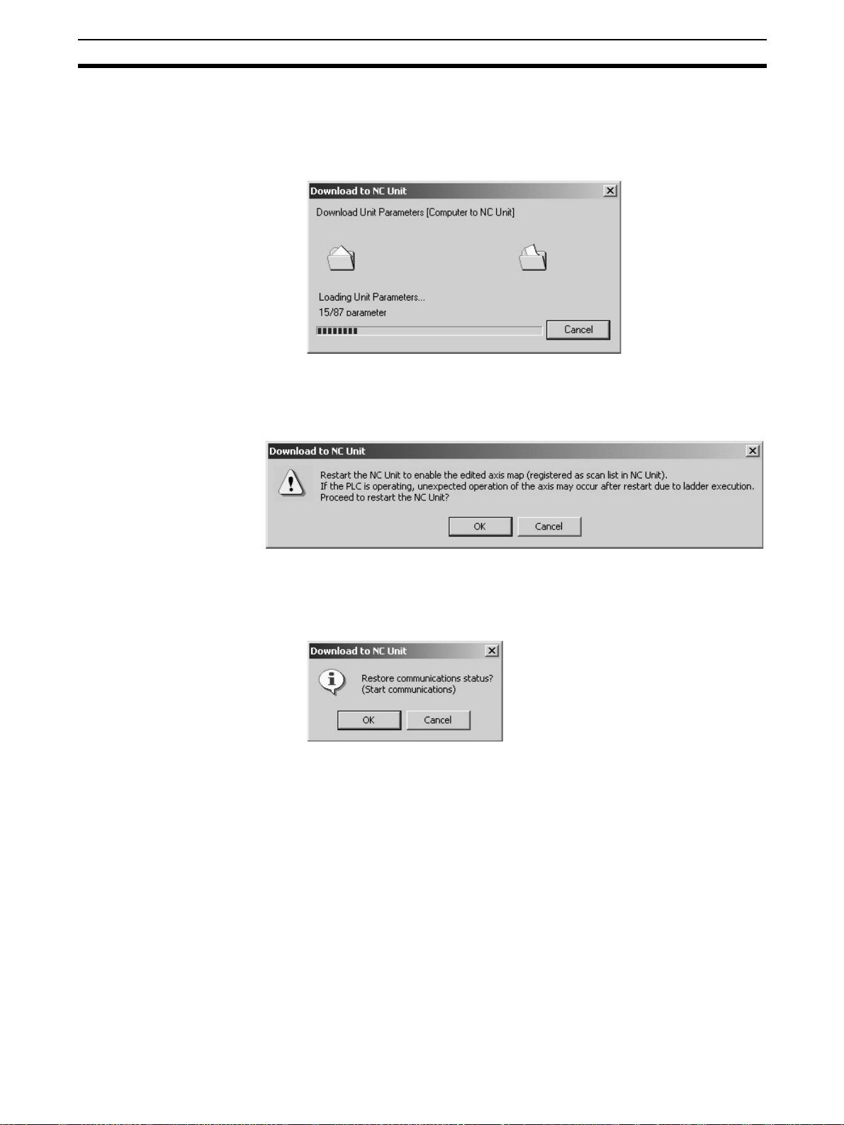
Downloading Data Section 7-3
3. Click the OK Button to release the connection and start downloading Unit
Parameters to the Position Control Unit.
Clicking the Cancel Button will cancel downloading, however, the parameters that were downloaded before the cancellation should be downloaded
to the Position Control Unit.
4. If the checkbox for writing to flash memory was selected a few steps before, the following dialog box will be displayed to confirm that the Position
Control Unit will be restarted to enable the registered axis map after completion of the download.
5. Click the OK Button to restart the Position Control Unit.
6. If the connection was released on the Step 2., the connection status can
be restored (established in this case) here. To establish the connection,
click the OK Button. Otherwise, click the Cancel Button.
7. When the Download to NC Unit Dialog Box is closed, the download will be
completed.
7-3-3 Downloading Servo Parameters
1,2,3... 1. Click the Download Button in the Edit Servo Parameter Window.
The checkbox of Selected Parameters will be displayed. To download only
the selected parameters, select the checkbox. If the checkbox is not selected here, all the Servo Parameters will be downloaded.
63

Downloading Data Section 7-3
2. Click the OK Button.
If the communications between the Position Control Unit and Servo Driver
are not established at this point, the following dialog box will be displayed
to confirm whether to establish the connection or not.
3. Click the OK Button to establish the connection and start downloading Servo Parameters to the Servo Driver.
4. If the Servo Driver models do not match at this point, the following confirmation message will be displayed. To continue downloading, click the OK
Button.
5. Clicking the Cancel Button will cancel downloading, however, the parameters that were downloaded before the cancellation should be downloaded
to the Servo Driver.
64
6. If the connection was established at Step 2, the connection status can be
restored (released in this case) here. To release the connection, click the
OK Button. Otherwise, click the Cancel Button.

Uploading Data Section 7-4
7. When the Download to NC Unit Dialog Box is closed, the download will be
completed.
Note When the MECHATROLINK communications cannot be started, Servo
Parameters cannot be downloaded. Start the MECHATROLINK communications first and download Servo Parameters.
7-4 Uploading Data
The object of uploading varies depending on the operation method.
Batch Uploading Uploads Unit Parameters and Servo Parameters of all the Servo Drivers regis-
tered in the scan list on the Position Control Unit.
Uploading Unit
Parameters
Uploading Servo
Parameters
Note Before starting MECHATROLINK communications, make sure that the PLC is
Uploads Unit Parameters.
Uploads Servo Parameters.
in the PROGRAM Mode. Otherwise, the axis may start moving suddenly due
to the ladder execution.
Before disconnecting MECHATROLINK communications, make sure that the
axis is not operating. Disconnecting MECHATROLINK communications will
put the operating axis in the Servo Free state.
7-4-1 Batch Uploading
1,2,3... 1. On the Axis Map Setting Window, click Online/Upload from NC Unit, click
in the toolbar, or right-click the Position Control Unit and select Up-
load from NC Unit from the pop-up menu. The following dialog box will be
displayed.
2. Click the OK Button.
Cancels all the parameters being edited and close the Edit Windows.
3. Click the OK Button. Uploading Unit Parameters from the Position Control
Unit will start. Clicking the Cancel Button will cancel the upload.
65

Uploading Data Section 7-4
4. If the connection between the Position Control Unit and Servo Driver is not
established at this point, the following dialog box will be displayed.
5. Click the OK Button to establish the connection and start uploading Servo
Parameters from the Servo Driver.
Clicking the Cancel Button during uploading will cancel the upload.
66
If the connection cannot be established at this point, the following dialog
box will be displayed. Click the OK Button and the axes registered in the
Position Control Unit will be displayed as Unknown Model.
6. If the connection was established at Step 4, the connection status can be
restored (released in this case) here. To release the connection, click the
OK Button. To leave the connection established, click the Cancel Button.

Uploading Data Section 7-4
7. When the Upload from NC Unit Dialog Box is closed, the upload will be
completed.
Note Batch uploading will overwrite the parameters on the computer, which means
that the parameters being edited will also be erased.
When the MECHATROLINK communications cannot be started, only Unit
Parameters can be uploaded.
7-4-2 Uploading Unit Parameters
1,2,3... 1. Click the Upload Button in the Edit Unit Parameter Window.
2. Clicking the OK Button will start uploading Unit Parameters from the Position Control Unit.
Clicking the Cancel Button will cancel uploading.
3. When the Upload from NC Unit Dialog Box is closed, the upload will be
completed.
Note When the axis map on the computer is different from the scan list in the Posi-
tion Control Unit, Unit Parameters will not be uploaded. Execute batch upload
instead.
7-4-3 Uploading Servo Parameters
1,2,3... 1. Click the Upload Button in the Edit Servo Parameter Window. The follow-
ing dialog box will be displayed.
2. Click the OK Button.
If the connection between the Position Control Unit and Servo Driver are
not established at this point, the following dialog box will be displayed to
confirm whether to establish the connection or not.
67

Comparing Data Section 7-5
3. Click the OK Button to establish communications and start uploading Servo Parameters from the Servo Driver.
4. If the Servo Driver models do not match, the following confirmation message will be displayed. To continue uploading, click the OK Button.
5. Click the Cancel Button to cancel uploading.
6. If the connection was established on Step 2, the connection status can be
restored (released in this case) here. To release the connection, click the
OK Button. To leave the connection established, click the Cancel Button.
7. When the Upload from NC Unit Dialog Box is closed, the upload will be
completed.
Note When the MECHATROLINK communications cannot be started, Servo
Parameters cannot be uploaded. Start the MECHATROLINK communications
first and upload Servo Parameters.
7-5 Comparing Data
The objects of comparing varies depending on the operation method.
Batch Comparing Compares the data on CX-Motion-NCF with the Unit Parameters and Servo
Parameters of the Servo Drivers registered in the scan list on the Position
Control Unit.
68

Comparing Data Section 7-5
Comparing Unit
Parameters
Comparing Servo
Parameters
Note Before starting MECHATROLINK communications, make sure that the PLC is
Compares the data on CX-Motion-NCF with the Unit Parameters on the Position Control Unit.
Compares the data on CX-Motion-NCF with the Servo Parameters on the
Servo Driver.
in the PROGRAM Mode. Otherwise, the axis may start moving suddenly due
to the ladder execution.
Before disconnecting MECHATROLINK communications, make sure that the
axis is not operating. Disconnecting MECHATROLINK communications will
put the operating axis in the Servo Free state.
7-5-1 Batch Comparing
1,2,3... 1. On the Axis Map Setting Window, click Online/Compare, click in the
2. Click the OK Button. All the parameters being edited will be discarded and
toolbar, or right-click the Position Control Unit and select Compare from
the pop-up menu. The following dialog box will be displayed.
the Edit Windows will be closed.
3. Click the OK Button. Uploading Unit Parameters from the Position Control
Unit will start. Clicking the Cancel Button will cancel the upload.
4. If the communications between the Position Control Unit and Servo Driver
are not established at this point, the following dialog box will be displayed
to confirm whether to establish the connection or not.
69

Comparing Data Section 7-5
5. Click the OK Button to establish the connection and start uploading Servo
Parameters from the Servo Driver.
Clicking the Cancel Button will cancel the upload.
If the connection cannot be established at this point, the following dialog
box will be displayed. Click the OK Button and the axes registered in the
Position Control Unit will be displayed as Unknown Model on the Axis Map
Setting Window.
6. If the connection was established on Step 4, the connection status can be
restored (released in this case) here. To release the connection, click the
OK Button. To leave the connection established, click the Cancel Button.
7. After completion of uploading Unit and Servo Parameters, they are compared with the parameters on the personal computer. If they match, the following dialog box will be displayed.
If there is any mismatch in the comparison, the following window will be
displayed to show the parameters that did not match.
70

Comparing Data Section 7-5
Note When the MECHATROLINK communications cannot be started, batch com-
paring cannot be executed. Start the MECHATROLINK communications first
and execute batch comparing.
7-5-2 Comparing Unit Parameters
1,2,3... 1. Click the Compare Button in the Edit Unit Parameter Window. The follow-
ing dialog box will be displayed.
2. Click the OK Button to start comparing. Uploading Unit Parameters will
start at first.
Clicking the Cancel Button during comparing will cancel comparing.
3. After completion of uploading, the following dialog box will be displayed if
Unit Parameters have no mismatch.
If there is any mismatch in the comparison, the following window will be
displayed to show the parameters that did not match.
71

Comparing Data Section 7-5
7-5-3 Comparing Servo Parameters
1,2,3... 1. Click the Compare Button in the Edit Servo Parameter Window. The fol-
lowing dialog box will be displayed.
2. Click the OK Button.
If the communications between the Position Control Unit and Servo Driver
are not established at this point, the following dialog box will be displayed
to confirm whether to establish the connection or not.
3. Click the OK Button to establish the communications and start uploading
Servo Parameters.
4. If the Servo Driver models do not match, the following confirmation message will be displayed. To continue uploading, click the OK Button.
5. Clicking the Cancel Button during comparing will cancel comparing.
72

Writing to Flash Memory Section 7-6
6. If the connection was established on Step 2, the connection status can be
restored (released in this case) here. To release the connection, click the
OK Button. To leave the connection established, click the Cancel Button.
7. After completion of comparing, the following dialog box will be displayed if
Servo Parameters have no mismatch.
If there is any mismatch in the comparison, the following window will be
displayed to show the parameters that did not match.
Note When the MECHATROLINK communications cannot be started, Servo
Parameters cannot be compared. Start the communications first and compare
Servo Parameters.
7-6 Writing to Flash Memory
Unit Parameters downloaded to the Position Control Unit will be lost when the
power is turned OFF. Therefore, they have to be written to the flash memory to
keep them after powering OFF.
If Unit Parameters were not written to the flash memory during downloading
process, make sure to write them to the flash memory.
73

Writing to Flash Memory Section 7-6
Writing to Flash Memory
!Caution After downloading Unit Parameters to the Position Control Unit, always
backup the parameters in the flash memory. Otherwise, the parameter settings before the download will be enabled when the power is turned ON next
time (i.e. the downloaded parameters will be lost and not be reflected), which
may cause the machines to operate in an unexpected way.
1,2,3... 1. Click Online/Write Flash Memory, or click in the toolbar on the Axis
Map Setting Window. The following dialog box will be displayed.
2. Click the OK Button.
If the communications between the Position Control Unit and Servo Driver
are established at this point, the following dialog box will be displayed to
confirm whether to release the connection or not.
3. Click the OK Button.
The following dialog box will be displayed to confirm whether to restart the
Position Control Unit or not. To enable the Unit Parameters written to the
flash memory, the Position Control Unit has to be restarted.
4. If the connection was released on Step 2, the connection status can be restored (established in this case) here. To establish the connection, click the
OK Button. To leave the connection released, click the Cancel Button.
5. The writing operation is completed when the Write to flash memory window is no longer displayed.
74
Note If an error occurs in writing to the flash memory, the Unit Parameters may not
be written to the flash memory successfully. In this case, write the Unit Parameters to the flash memory again after resetting the error.

SECTION 8
Monitor
The Position Control Unit's communications status, error status, and axis's present position and status are displayed in the
Monitor Windows.
Note Make sure that the computer and PLC are connected with the connection cable and the communica-
tions between them are established before starting monitoring operations.
8-1 Unit Monitor . . . . . . . . . . . . . . . . . . . . . . . . . . . . . . . . . . . . . . . . . . . . . . . . . . 76
8-2 Axis Monitor. . . . . . . . . . . . . . . . . . . . . . . . . . . . . . . . . . . . . . . . . . . . . . . . . . 79
75

Unit Monitor Section 8-1
8-1 Unit Monitor
In Unit Monitor, communications status, Position Control Unit errors, and
present position of each axis are monitored.
Starting Unit Monitor (Unit Monitor Common Items, Unit Status Monitor, Present
Position Monitor)
1,2,3... 1. On the Axis Map Setting Window, click Online/Unit Monitor, or click
in the toolbar, or right-click on the Position Control Unit and select Unit
Monitor from the pop-up menu.
If the connection to the Position Control Unit is not established at this point,
the following dialog box will be displayed.
2. Click the OK Button to establish the connection (i.e., start communications).
76
3. Click to stop monitoring. Clicking the same button again will restart
monitoring.
4. Click the Present Position Tab to display the Present Position Monitor Tab
Page.

Unit Monitor Section 8-1
5. Click the Close Button or at the right top corner to end monitoring the
Position Control Unit.
Unit Monitor Common Items
Title Bar Shows the status of monitoring and communications between
Monitor Start/Stop
Button
Close Button Closes the monitor window.
Unit Status Monitor
Scan list Indicates whether the axes are registered in the
Comm (Communications) status Indicates whether the communications with the
Axis error Displays the axis where an error or warning has
Name Explanation
Position Control Unit and Servo Driver.
• Stop: Monitoring stopped.
• Monitoring (Connection Released): Monitoring in progress,
however, communications between Position Control Unit and
Servo Driver have not been started. Therefore, information
about axes is not displayed.
• Monitoring (Connection Established): Entire information is
displayed.
Starts monitoring. If communications between Position Control Unit and Servo Driver have not been
started, the connection will be established first.
Stops monitoring.
Item Explanation
scan list or not.
axis 1 to 16 are established or not.
occurred.
With errors:
With warnings:
77

Unit Monitor Section 8-1
Item Explanation
Unit common
error
1,2,3... 1. When an error occurs on the Position Control Unit, the following window
will be displayed.
Error reset all Pressing this button will reset all the error occur-
ring on the Position Control Unit and Servo Drivers.
Error code Displays the error code of the error occurring on
the Position Control Unit. When there is no error,
the code [0000] is displayed.
Error name Displays the name of the error occurring on the
Position Control Unit.
2. When an error or warning occurs on an axis, the following window will be
displayed.
78

Axis Monitor Section 8-2
Present Position Monitor
Item Explanation
Command value Displays the command value of each axis.
Feedback value Displays the feedback value of each axis.
Monitor all axes with
command unit
Note When performing Unit Monitor, set the Input Memory Area of the Axis Operat-
ing Memory Area Designation on the Edit Unit Parameter Window and transfer the setting to the Position Control Unit. If it is not set, the data in the Unit is
monitored directly, which makes the response slower.
If selected (i.e., checked), all the axes will be monitored using
command unit. Pulse rate and unit are set in Axis Monitor.
8-2 Axis Monitor
In Axis Monitor, present values, status, external I/O, and error information of
axes are monitored.
Starting Axis Monitor (Axis Monitor Common Items, Basic Monitor, Status Monitor,
Present Value Monitor)
1,2,3... 1. On the Axis Map Setting Window, click Online/Axis Monitor, click in
the toolbar, or right-click the Position Control Unit or Servo Driver and select Axis Monitor. If the communications between the Position Control
Unit and Servo Driver have not been established at this point, the following
dialog box will be displayed.
2. Click the OK Button to start communications (i.e., establish connection).
79

Axis Monitor Section 8-2
3. In the drop-down list of Monitored Axes, the axes registered in the scan list
of the Position Control Unit will be displayed. Select axes to be monitored.
80

Axis Monitor Section 8-2
4. Click the Basic Monitor Tab to display present values and errors.
5. Click the Status Tab to display all the statuses.
81

Axis Monitor Section 8-2
6. Click the Present Value Tab to display various present values.
7. Click to stop monitoring. Clicking the same button again will resume
8. Click the Close Button or at the right top corner of the window to close
Note When performing Unit Monitor, set the Input Memory Area of the Axis Operat-
ing Memory Area Designation on the Edit Unit Parameter Window and transfer the setting to the Position Control Unit. If it is not set, the data in the Unit is
monitored directly, which makes the response slower.
Axis Monitor Common Items
Title Bar Shows the status of monitoring and communications between
monitoring.
the Axis Monitor Window.
Name Explanation
Position Control Unit and Servo Driver.
• Stop: Monitoring stopped.
• Monitoring (Connection Released): Monitoring in progress,
however, communications between Position Control Unit and
Servo Driver have not been started. Therefore, information
about axes is not displayed.
• Monitoring (Connection Established): Entire information is
displayed.
82

Axis Monitor Section 8-2
Name Explanation
Monitor Start/Stop
Button
Close Button Closes the monitor window.
Starts monitoring. If communications between Position Control Unit and Servo Driver have not been
started, the connection will be established first.
Stops monitoring.
Selected Axis
Name Explanation
Selected Axis Specifies axes to be monitored. The axes registered in the
scan list of the Position Control Unit are displayed in the dropdown list.
Status
Name Explanation
Status Communications Status Status of each signal is displayed.
SERVO ON
PCU Positioning Completed
No Origin Flag
Brake Output
Forward Rotation Limit Input
Reverse Rotation Limit Input
Origin Proximity Input
Encoder Phase Z Input
External Latch Signal 1 Input
External Latch Signal 2 Input
External Latch Signal 3 Input
Basic Monitor
Name Explanation
Present Value Present Value
Display
Monitor Setup
Button
Error Error Status of errors is displayed.
Error code When an error occurs, the error code will be dis-
Error Name When an error occurs, the error name will be
Present position, speed, etc. are displayed.
Press this button to change displayed contents,
unit, and pulse rate.
Unit and pulse rate can be set only for the axes
registered in the Axis Map Setting Window.
With errors:
With warnings:
played. When there is no error, the code [0000]
will be displayed. Click the error code to display
help.
displayed. Click the error name to display help.
1,2,3... 1. Click the Setup Button to display the Monitor Setup Window.
2. Specify the type of monitored present value, unit, and pulse rate
3. Once setup is completed, click the OK Button to determine the settings. To
discard the settings, click the Cancel Button.
83
 Loading...