

Page 1

Cat. No. W428-E1-02
SYSMAC
WS02-LCMC1-EV2
CX-Process Monitor Plus
(Ver. 2)
OPERATION MANUAL
Page 2

WS02-LCMC1-EV2 CX-Process Monitor Plus (Ver. 2)
Operation Manual
Revised January 2007
Page 3

iv
Page 4

Notice:
r
f
OMRON products are manufactured for use according to proper procedures by a qualified operator
and only for the purposes described in this manual.
The following conventions are used to indicate and classify precautions in this manual. Always heed
the information provided with them. Failure to heed precautions can result in injury to people or damage to property.
!DANGER Indicates an imminently hazardous situation which, if not avoided, will result in death or
serious injury.
!WARNING Indicates a potentially hazardous situation which, if not avoided, could result in death or
serious injury.
!Caution Indicates a potentially hazardous situation which, if not avoided, may result in minor or
moderate injury, or property damage.
OMRON Product References
All OMRON products are capitalized in this manual. The word “Unit” is also capitalized when it refers to
an OMRON product, regardless of whether or not it appears in the proper name of the product.
The abbreviation “Ch,” which appears in some displays and on some OMRON products, often means
“word” and is abbreviated “Wd” in documentation in this sense.
The abbreviation “PLC” means Programmable Controller. “PC” is used, however, in some Programming Device displays to mean Programmable Controller.
Visual Aids
The following headings appear in the left column of the manual to help you locate different types of
information.
Note Indicates information of particular interest for efficient and convenient opera-
tion of the product.
1,2,3... 1. Indicates lists of one sort or another, such as procedures, checklists, etc.
Before Installing the CX-Process Monitor Plus
Installing the CX-Process Monitor Plus signifies that you accept the software user’s license agreement
displayed during the installation process. Do not install this software if you do not accept the user’s
license agreement. Warranty and after-sales services are available only to users that register with the
enclosed registration form. Please fill in the registration form and return it to OMRON.
OMRON, 2005
All rights reserved. No part of this publication may be reproduced, stored in a retrieval system, or transmitted, in any form, o
by any means, mechanical, electronic, photocopying, recording, or otherwise, without the prior written permission o
OMRON.
No patent liability is assumed with respect to the use of the information contained herein. Moreover, because OMRON is constantly striving to improve its high-quality products, the information contained in this manual is subject to change without
notice. Every precaution has been taken in the preparation of this manual. Nevertheless, OMRON assumes no responsibility
for errors or omissions. Neither is any liability assumed for damages resulting from the use of the information contained in
this publication.
v
Page 5

vi
Page 6

TABLE OF CONTENTS
PRECAUTIONS . . . . . . . . . . . . . . . . . . . . . . . . . . . . . . . . . . . xi
1 Intended Audience. . . . . . . . . . . . . . . . . . . . . . . . . . . . . . . . . . . . . . . . . . . . . . . . . . . . . . . . . xii
2 General Precautions. . . . . . . . . . . . . . . . . . . . . . . . . . . . . . . . . . . . . . . . . . . . . . . . . . . . . . . . xii
3 Safety Precautions . . . . . . . . . . . . . . . . . . . . . . . . . . . . . . . . . . . . . . . . . . . . . . . . . . . . . . . . . xii
4 Application Precautions. . . . . . . . . . . . . . . . . . . . . . . . . . . . . . . . . . . . . . . . . . . . . . . . . . . . .xiv
SECTION 1
Introduction. . . . . . . . . . . . . . . . . . . . . . . . . . . . . . . . . . . . . . . 1
1-1 CX-Process Monitor Plus . . . . . . . . . . . . . . . . . . . . . . . . . . . . . . . . . . . . . . . . . . . . . . . . . . .2
1-2 Basic Operating Procedure . . . . . . . . . . . . . . . . . . . . . . . . . . . . . . . . . . . . . . . . . . . . . . . . . .23
SECTION 2
Setup. . . . . . . . . . . . . . . . . . . . . . . . . . . . . . . . . . . . . . . . . . . . . 27
2-1 Installation . . . . . . . . . . . . . . . . . . . . . . . . . . . . . . . . . . . . . . . . . . . . . . . . . . . . . . . . . . . . . . . 28
2-2 Connecting the PLC. . . . . . . . . . . . . . . . . . . . . . . . . . . . . . . . . . . . . . . . . . . . . . . . . . . . . . . . 47
SECTION 3
Exchanging Data with Monitor Plus . . . . . . . . . . . . . . . . . . . 51
3-1 Data Exchange Method . . . . . . . . . . . . . . . . . . . . . . . . . . . . . . . . . . . . . . . . . . . . . . . . . . . . .52
3-2 Example Function Blocks for Data Exchange. . . . . . . . . . . . . . . . . . . . . . . . . . . . . . . . . . . . 62
3-3 Loop Control Unit Precautions . . . . . . . . . . . . . . . . . . . . . . . . . . . . . . . . . . . . . . . . . . . . . . . 72
SECTION 4
Monitor Screen Functions and Operations . . . . . . . . . . . . . 73
4-1 Outline . . . . . . . . . . . . . . . . . . . . . . . . . . . . . . . . . . . . . . . . . . . . . . . . . . . . . . . . . . . . . . . . . . 74
4-2 Using the CX-Process Monitor Plus . . . . . . . . . . . . . . . . . . . . . . . . . . . . . . . . . . . . . . . . . . . 74
4-3 CX-Process Tool Procedures . . . . . . . . . . . . . . . . . . . . . . . . . . . . . . . . . . . . . . . . . . . . . . . . . 75
4-4 Starting and Stopping the CX-Process Monitor Plus . . . . . . . . . . . . . . . . . . . . . . . . . . . . . . 78
4-5 Overview Screen . . . . . . . . . . . . . . . . . . . . . . . . . . . . . . . . . . . . . . . . . . . . . . . . . . . . . . . . . . 80
4-6 Screen Configurations . . . . . . . . . . . . . . . . . . . . . . . . . . . . . . . . . . . . . . . . . . . . . . . . . . . . . . 81
4-7 Control Screens . . . . . . . . . . . . . . . . . . . . . . . . . . . . . . . . . . . . . . . . . . . . . . . . . . . . . . . . . . . 82
4-8 Tuning Screens . . . . . . . . . . . . . . . . . . . . . . . . . . . . . . . . . . . . . . . . . . . . . . . . . . . . . . . . . . . 90
4-9 Trend Screens . . . . . . . . . . . . . . . . . . . . . . . . . . . . . . . . . . . . . . . . . . . . . . . . . . . . . . . . . . . . 95
4-10 Batch Trend Screens . . . . . . . . . . . . . . . . . . . . . . . . . . . . . . . . . . . . . . . . . . . . . . . . . . . . . . . 102
4-11 Segment Program 2 Screens . . . . . . . . . . . . . . . . . . . . . . . . . . . . . . . . . . . . . . . . . . . . . . . . . 111
4-12 Graphic Screens . . . . . . . . . . . . . . . . . . . . . . . . . . . . . . . . . . . . . . . . . . . . . . . . . . . . . . . . . . . 123
4-13 Annunciator Screens . . . . . . . . . . . . . . . . . . . . . . . . . . . . . . . . . . . . . . . . . . . . . . . . . . . . . . . 124
4-14 Operation Guide Screens . . . . . . . . . . . . . . . . . . . . . . . . . . . . . . . . . . . . . . . . . . . . . . . . . . . . 125
4-15 Alarm Log Screens . . . . . . . . . . . . . . . . . . . . . . . . . . . . . . . . . . . . . . . . . . . . . . . . . . . . . . . . 127
4-16 Operation Log Screens . . . . . . . . . . . . . . . . . . . . . . . . . . . . . . . . . . . . . . . . . . . . . . . . . . . . . 128
4-17 System Monitor Screens . . . . . . . . . . . . . . . . . . . . . . . . . . . . . . . . . . . . . . . . . . . . . . . . . . . . 129
4-18 System Monitor Log Screens. . . . . . . . . . . . . . . . . . . . . . . . . . . . . . . . . . . . . . . . . . . . . . . . . 138
vii
Page 7

TABLE OF CONTENTS
SECTION 5
Configuration Screens . . . . . . . . . . . . . . . . . . . . . . . . . . . . . . 139
5-1 Basic Configuration Procedure . . . . . . . . . . . . . . . . . . . . . . . . . . . . . . . . . . . . . . . . . . . . . . . 140
5-2 Basic Configuration Operations . . . . . . . . . . . . . . . . . . . . . . . . . . . . . . . . . . . . . . . . . . . . . . 141
5-3 System Monitor Settings . . . . . . . . . . . . . . . . . . . . . . . . . . . . . . . . . . . . . . . . . . . . . . . . . . . .144
5-4 Creating Graphic Screens . . . . . . . . . . . . . . . . . . . . . . . . . . . . . . . . . . . . . . . . . . . . . . . . . . .147
5-5 Screen Configuration. . . . . . . . . . . . . . . . . . . . . . . . . . . . . . . . . . . . . . . . . . . . . . . . . . . . . . . 177
5-6 System Information Settings . . . . . . . . . . . . . . . . . . . . . . . . . . . . . . . . . . . . . . . . . . . . . . . . . 206
5-7 Checking Configurations. . . . . . . . . . . . . . . . . . . . . . . . . . . . . . . . . . . . . . . . . . . . . . . . . . . .226
SECTION 6
Troubleshooting . . . . . . . . . . . . . . . . . . . . . . . . . . . . . . . . . . . 229
Appendices
A Reading/Writing Function Block ITEMs . . . . . . . . . . . . . . . . . . . . . . . . . . . . . . . . . . . . . . . 233
B Differences between Trend Screens and Batch Trend Screens . . . . . . . . . . . . . . . . . . . . . . . 253
Revision History . . . . . . . . . . . . . . . . . . . . . . . . . . . . . . . . . . . 255
viii
Page 8

About this Manual:
This manual describes the installation and operation of the WS02-LCMC1-EV2 CX-Process Monitor
Plus software package and includes the sections described below. The CX-Process Monitor Plus is
used to control and monitor the operation of the CS1W-LC001 Loop Control Unit, the CS1W-LCB01
Loop Control Board, the CS1W-LCB05 Loop Control Board, the CS1D-CPU@@P Process-control CPU
Units, and the CJ1G-CPU@@P Loop-control CPU Units.
Please read this manual carefully and be sure you understand the information provided before
attempting to install and operate the CX-Process Monitor Plus. Please read the following manuals
carefully and be sure you understand the information provided before setting up or using an application
for a Loop Control Unit or Loop Control Board.
Product Manual name Cat. No. Contents
WS02-LCMC1-EV2 CX-Process Monitor
Plus Operation Manual
WS02-LCTC1-EV5
CX-Process Tool
CS1W-LC001
Loop Control Unit
CS1W-LCB01/05
Loop Control Boards,
CS1D-CPU@@P
Process-control CPU
Units, and
CJ1G-CPU@@P
Loop-control CPU
Units
CS1W-LC001
Loop Control Unit
CS1W-LCB01/05
Loop Control Boards,
CS1D-CPU@@P
Process-control CPU
Units, and
CJ1G-CPU@@P
Loop-control CPU
Units
CX-Process Tool
Operation Manual
Loop Control Unit
Operation Manual
Loop Control Boards
Operation Manual
Loop Control Unit
Function Block Reference Manual
Loop Control Boards
Function Block Reference Manual
W428
(this manual)
W372 Installation and operation procedures for the
W374 Installation and operation procedures for the
W406 Installation and operation procedures for the
W375 Detailed information on function blocks for
W407 Detailed information on function blocks for
Installation and operation procedures for the
CX-Process Monitor Plus.
CX-Process Tool.
Loop Control Unit (except for function blocks).
Loop Control Boards (except for function
blocks).
Loop Control Units.
Loop Control Boards.
Section 1 introduces the CX-Process Monitor Plus.
Section 2 describes installing the CX-Process Monitor Plus and connections to the PLC.
Section 3 described data exchange for the CX-Process Monitor Plus
Section 4 describes the monitor screens used with the CX-Process Monitor Plus.
Section 5 describes the procedures to create screens and monitor using the CX-Process Monitor
Plus.
Section 6 describes errors that can occur while using the CX-Process Monitor Plus.
The Appendix provides a list of ITEM settings for function blocks.
!WARNING Failure to read and understand the information provided in this manual may result in per-
sonal injury or death, damage to the product, or product failure. Please read each section
in its entirety and be sure you understand the information provided in the section and
related sections before attempting any of the procedures or operations given.
ix
Page 9

x
Page 10

PRECAUTIONS
This section provides general precautions for using the CX-Process Monitor Plus.
The information contained in this section is important for the safe and reliable application of the CX-Process
Monitor Plus. You must read this section and understand the information contained before attempting to set up or
operate the CX-Process Monitor Plus.
1 Intended Audience . . . . . . . . . . . . . . . . . . . . . . . . . . . . . . . . . . . . . . . . . . . . . xii
2 General Precautions . . . . . . . . . . . . . . . . . . . . . . . . . . . . . . . . . . . . . . . . . . . . xii
3 Safety Precautions. . . . . . . . . . . . . . . . . . . . . . . . . . . . . . . . . . . . . . . . . . . . . . xii
4 Application Precautions . . . . . . . . . . . . . . . . . . . . . . . . . . . . . . . . . . . . . . . . . xiv
xi
Page 11

Intended Audience 1
1 Intended Audience
This manual is intended for the following personnel, who must also have
knowledge of electrical systems (an electrical engineer or the equivalent) and
knowledge about instrumentation system.
• Personnel in charge of installing FA systems.
• Personnel in charge of designing FA systems.
• Personnel in charge of managing FA systems and facilities.
2 General Precautions
The user must operate the product according to the performance specifications described in the operation manuals.
Before using the product under conditions which are not described in the
manual or applying the product to nuclear control systems, railroad systems,
aviation systems, vehicles, combustion systems, medical equipment, amusement machines, safety equipment, petrochemical plants, and other systems,
machines, and equipment that may have a serious influence on lives and
property if used improperly, consult your OMRON representative.
Make sure that the ratings and performance characteristics of the product are
sufficient for the systems, machines, and equipment, and be sure to provide
the systems, machines, and equipment with double safety mechanisms.
This manual provides information for programming and operating the Unit. Be
sure to read this manual before attempting to use the Unit and keep this manual close at hand for reference during operation.
!WARNING It is extremely important that a PC and all PC Units be used for the specified
purpose and under the specified conditions, especially in applications that can
directly or indirectly affect human life. You must consult with your OMRON
representative before applying a PC System to the above-mentioned applications.
3 Safety Precautions
!WARNING Check the following items before starting Loop Control Unit operation:
Analog I/O Units used in combination with the Loop Control Unit must be
mounted correctly, and the unit number set on the front panel of the Analog I/
O Unit must be the same as the unit number set on the Field Terminal Function Block. If the unit numbers are not the same, I/O (read/write) will be performed on the data for another Special I/O Unit (i.e., the one whose unit
number is set in the Field Terminal Function Block).
The initial settings of the System Common Block on the Loop Control Unit
must be set correctly. In particular, make sure that the Data Memory for the
Node Terminals in the CPU Unit controlling the Loop Control Unit is not used
for other applications on the PC. If the same words in Data Memory are used
for more than one application, the PC system may act unexpectedly and
cause injury.
xii
Page 12

Safety Precautions 3
When writing data to the I/O memory in the CPU Unit with function blocks
(e.g., using Send All Blocks, Expanded DO/AO Terminal to CPU Unit, or DO/
AO Terminal to CPU Unit), be sure that the words written to in the I/O memory
are not being used for any other purpose. If I/O memory words are allocated
to more than one purpose, the PC system may act unexpectedly and cause
injury.
!WARNING Check the following items before starting to run the Loop Control Board:
• Do not allow the bank of the EM Area with the number specified for allocation to the HMI (human-machine interface) data to be used by the CPU
Unit or other Units for any other purpose. The bank allocated for the HMI
is specified in ITEM 050 (EM Area Bank Allocated for HMI Memory = 0 to
12) of the System Common block. If the same memory area is used for
more than one purpose, the system may operate in an unexpected fashion, which may result in injury.
• Do not allow the area to which user link table data is written to be used by
the CPU Unit or other Units for any other purpose. If the same memory
area is used for more than one purpose, the system may operate in an
unexpected fashion, which may result in injury.
• Analog Input/Output Units used in combination with the Loop Control
Board must be mounted correctly, and the unit number set on the front
panel of the Analog Input/Output Unit must match the unit number set on
the Field Terminal block. If the unit numbers do not match, input/output
(read/write) will be performed on the data of another Special I/O Unit (i.e.,
the one whose unit number is set on the Field Terminal block).
• The defaults of the System Common block on the Loop Control Board
must be set correctly.
!WARNING Always stop the operation of the Loop Control Board before converting any of
the EM Area to file memory. If any part of the EM Area that is being used by
the Loop Control Board for the HMI is converted to file memory during Board
operation, the system may operate in an unexpected fashion, which may
result in injury.
!WARNING Do not perform processing in such a way that the Loop Control Unit/Board
and CPU Unit write to identical I/O memory words allocated to a contact output or analog output of an external Unit. If the same words are written to, the
externally connected loads may act unexpectedly and cause injury.
!WARNING Fail-safe measures must be taken by the customer to ensure safety in the
event of incorrect, missing, or abnormal signals caused by broken signal lines,
momentary power interruptions, or other causes.
!Caution Before transferring function block data (initial setting data or operation data) to
the Loop Control Unit/Board, confirm that the destination for the data is correct and also confirm the overall safety of the system (including the Loop Control Unit/Board). Not doing so may result in unexpected operation.
xiii
Page 13

Application Precautions 4
!Caution After updating the tag settings or network configuration for CX-Process Moni-
tor Plus, always confirm that the Monitor Plus screens will operate properly
with the new settings or configuration before attempting actual operation. If
the settings or configuration is not appropriate, unexpected operation may
result.
4 Application Precautions
Observe the following precautions when using CX-Process Monitor Plus.
!Caution Loop Control Unit/Board data is monitored and operated using CX-Process
Monitor Plus based on the tag files for Monitor Plus created using CX-Process
Tool. CX-Process Tool can be used on Microsoft Windows 95, 98, Me, 2000,
or NT (Service Pack 4 or later). CX-Process Tool Ver. 3.2 or higher must be
used to output tag files for the CX-Process Monitor Plus.
!Caution Before using function block data in actual operation, confirm operation by
monitoring run status (to check the load rate; select Execute/Operation/Mon-
itor Run Status) and validating actions (select Validate Action/Start) with
CX-Process Tool. In particular, be sure to confirm that the load rate will be
less than 60%. (For details on the load rate, refer to the Loop Control Unit/
Board Operation Manual.)
!Caution The Loop Control Unit/Board can read and write I/O memory in the CPU Unit
using the Field Terminal Function Blocks or CPU Terminal Blocks independent of the user program (Step Ladder Program) in the CPU Unit. Do not write
to the same I/O memory words from both the Loop Control Unit/Board and the
CPU Unit.
!Caution To hold an analog output or contact output at a specific value (for example, the
maximum value or minimum value) when the Loop Control Unit/Board stops
running, create a Step Ladder Program in the CPU Unit so that the corresponding output bit allocated to Analog Output Unit or Contact Output Unit is
set to the desired value using an NC condition of the Loop Control Unit/Board
Running Flag (bit 00 in allocated CIO word “n”) as an input condition.
!Caution If a fatal error occurs in the CPU Unit (including fatal errors created by execu-
tion of an FALS instruction), the Loop Control Unit/Board will also stop running. To hold analog outputs to the previous values before the stop occurred,
and to set analog outputs to either the minimum value or maximum value, use
the output hold function of the Analog Output Unit or Analog I/O Unit.
!Caution Before turning ON the power to the PC, make sure that the facilities are safe.
The analog output values and contact outputs from the Loop Control Unit/
Board are updated when the power to the PC is turned ON regardless of the
operating mode of the CPU Unit (including in the PROGRAM mode). (Internally, the analog output values and contact outputs are sent from the CPU
Unit to Basic I/O Units and Analog Output Units.)
xiv
!Caution Fail-safe measures must be taken by the customer to ensure safety in the
event of incorrect, missing, or abnormal signals caused by broken signal lines,
momentary power interruptions, or other causes.
Page 14

Application Precautions 4
!Caution Confirm that no adverse effect will occur in the system before attempting any
of the following:
• Changing the operating mode of the PC (including the setting of the Startup Mode)
• Force-setting/force-resetting any bit in memory
• Changing the present value or any set value in memory
!Caution Be sure that all mounting screws, terminal screws, and cable connector
screws are tightened to the torque specified in the user manuals. Incorrect
tightening torque may result in malfunction.
!Caution In the event of system or power failure, CX-Process function files (extension
“.ist”) may not be saved. It is recommended that function files are saved regularly.
!Caution If the power supply is turned OFF while function block data is being backed up
from RAM to flash memory, the backup will not be completed normally. If the
power supply is turned back ON within 24 hours, however, the super capacitor
will have held the RAM data. The backup operation will restart when power is
turned ON and operation will start when the backup has been completed. If
the power supply is turned OFF for more than 24 hours, however, RAM data
will be lost and operation will be started with the data that was previously
saved to flash memory. If this happens, the Cold Start Auto-execution Flag
(A35807) will turn ON to show that the previous data has been used. Use this
bit in programming to take whatever steps are necessary, such as downloading the most recent function block data.
xv
Page 15

Application Precautions 4
xvi
Page 16

This section introduces the CX-Process Monitor Plus.
1-1 CX-Process Monitor Plus . . . . . . . . . . . . . . . . . . . . . . . . . . . . . . . . . . . . . . . . 2
1-1-1 Outline . . . . . . . . . . . . . . . . . . . . . . . . . . . . . . . . . . . . . . . . . . . . . . . 2
1-1-2 Screen Outlines. . . . . . . . . . . . . . . . . . . . . . . . . . . . . . . . . . . . . . . . . 4
1-1-3 CX-Process Monitor Plus System Requirements . . . . . . . . . . . . . . . 10
1-1-4 Relationship to CX-Process Tool . . . . . . . . . . . . . . . . . . . . . . . . . . . 14
1-1-5 Relation between Screens and Function Blocks. . . . . . . . . . . . . . . . 15
1-1-6 CX-Process Monitor Plus Software Specifications . . . . . . . . . . . . . 16
1-1-7 CX-Process Monitor Plus Setting and Monitoring Capabilities. . . . 20
1-1-8 Files Created Using CX-Process Monitor Plus . . . . . . . . . . . . . . . . 21
1-1-9 Version Upgrade . . . . . . . . . . . . . . . . . . . . . . . . . . . . . . . . . . . . . . . . 21
1-2 Basic Operating Procedure . . . . . . . . . . . . . . . . . . . . . . . . . . . . . . . . . . . . . . . 23
SECTION 1
Introduction
1
Page 17

CX-Process Monitor Plus Section 1-1
1-1 CX-Process Monitor Plus
1-1-1 Outline
The CX-Process Monitor Plus is a Windows NT-based application that monitors the Function Block data within a Loop Control Unit/Board using Control
screens (on-site instrument images), Trend screens, Graphic screens, and
Annunciator screens, etc., via the Controller Link, serial communications, or
Ethernet. The CX-Process Monitor Plus is used together with the CX-Process
Tool to create function blocks for Loop Control Units/Boards.
You can also perform the following four functions.
Monitoring Function
Blocks in a Loop Control
Unit/Board
Controlling Function
Blocks in a Loop Control
Unit/Board
Monitoring Function Block
Alarm Status in a Loop
Control Unit/Board
Configuring CX-Process
Monitor Plus Screens
Monitor PV, SP, and MV, etc., within the Control Block, monitor analog signals,
and monitor contact signals.
Perform Run/Stop instructions in the Loop Control Unit/Board.
Display the status of the CPU Unit, such as the current operating mode.
Change settings, switch between auto and manual, and perform manual operations, tune PID constants, etc., in the Control Block.
You can perform stop block operation commands for each Control Block
(when using the Tuning screen).
Display Control Block and Alarm Block alarms if they occur, and store the
alarms in the alarm history.
You can configure the screen to suit your needs.
2
Page 18

CX-Process Monitor Plus Section 1-1
CX-Process Monitor Plus Functions
--- Screen Monitoring operating
User-defined
screens
System screens Alarm Log --- --- OK (Stored when an
Overview --- --- OK
Control OK (Display PV bar) OK (Change SP, switch
Tuning OK (Display PV, SP, and
MV trends for 1 loop)
Trend OK (Display Control Block
or analog signal trends)
Batch Trend OK (Display Control Block
Segment
Program 2
Graphic OK (Display status for
Annunciator --- --- OK (Use colors or sound
Operation Guide OK (Display message
System Monitor OK (Display the run/stop
Operation Log --- OK (Stores run operation
System Monitor
Log
or analog signal trends)
OK (Display Segment
Program 2 trends)
contact or analog signal
graphics)
when Internal Switch is
turned ON)
status for the Loop Control Unit/Board, display
Execution errors, RAM
checksum errors, and
battery errors, and monitor the status of the CPU
Unit control mode, etc.)
OK (Displays run/stop
command history and
Execution error history
when an error occurs)
status
Controlling operation Monitoring alarm status
between auto/manual,
and perform manual operations)
OK (Change SP, and
change P, I, D, etc.)
--- OK
--- ---
OK (Run/stop operation
at the relevant Segment
Program 2 Block)
OK (Turn ON/OFF the
contact, and set the analog value)
--- OK
OK (Run/stop command
for the Loop Control Unit/
Board)
history, e.g., SP change,
etc.)
--- OK
OK
OK (Change bar graph
colors)
OK (Errors related to the
relevant Segment Program 2 Block)
OK
to notify of an alarm)
OK
alarm occurs)
OK
Note Only the following data can be monitored and set with the CX-Process Moni-
tor Plus and tag names must be set to enable monitoring and setting. Use CXProcess Tool Ver. 3.2 or higher to set the tag names.
3
Page 19
CX-Process Monitor Plus Section 1-1
Data set/monitored
by CX-Process
Monitor Plus
Function block data Control Blocks:
Contact signals Contact signals through Contact Distributor (Block Model
Analog
signals
Sent to
Monitor Plus
Set from
Monitor Plus
Loop Control Unit Loop Control Board
Basic PID (Block Model 011), Advanced PID (Block Model
012), Blended PID (Block Model 013), Batch Flowrate Capture (Block Model 014), Indication and Setting (Block Model
031), Indication and Operation (Block Model 032), Ratio
Setting (Block Model 033), Indicator (Block Model 034), 2position ON/OFF (Block Model 001), and 3-position ON/
OFF (Block Model 002)
Operation Blocks:
High/Low Alarm (Block Model 111), Segment Program 2
(Block Model 157), ON/OFF Valve Manipulator (Block
Model 221), Motor Manipulator (Block Model 222), Reversible Motor Manipulator (Block Model 223), Motor Opening
Manipulator (Block Model 224), Timer (Block Model 205)
and Counter (Block Model 208)
201) + Internal Switch (Block Model 209)
Analog signals through Input Selector (Block Model 162)
Analog signals through Constant Generator (Block Model
166)
1-1-2 Screen Outlines
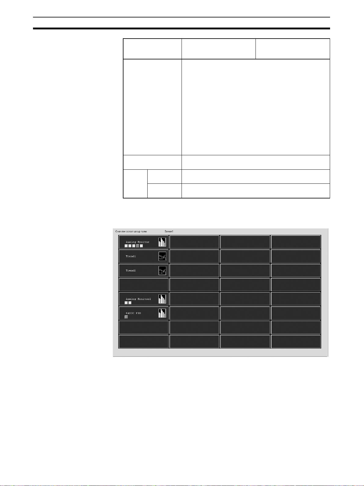
Overview Screen Possesses the functions of all menu screens and alarm display screens.
4
Page 20
CX-Process Monitor Plus Section 1-1
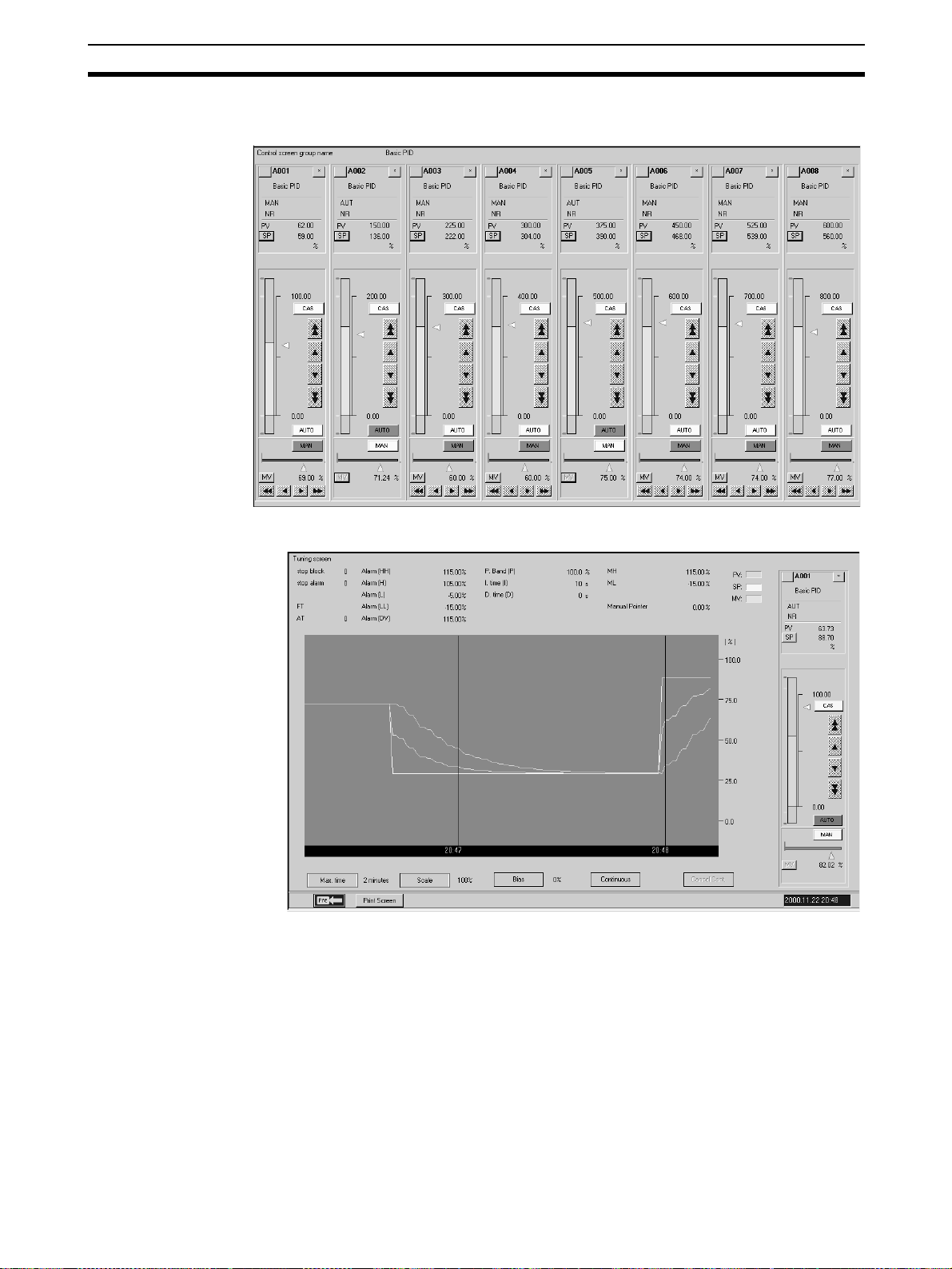
Control Screens Monitor and set the Control Block and part of the Operation Block, monitor
analog signals, and monitor and set contact signals.
Tuning Screens Use this screen to change Control Block P, I, D constants.
5
Page 21
CX-Process Monitor Plus Section 1-1
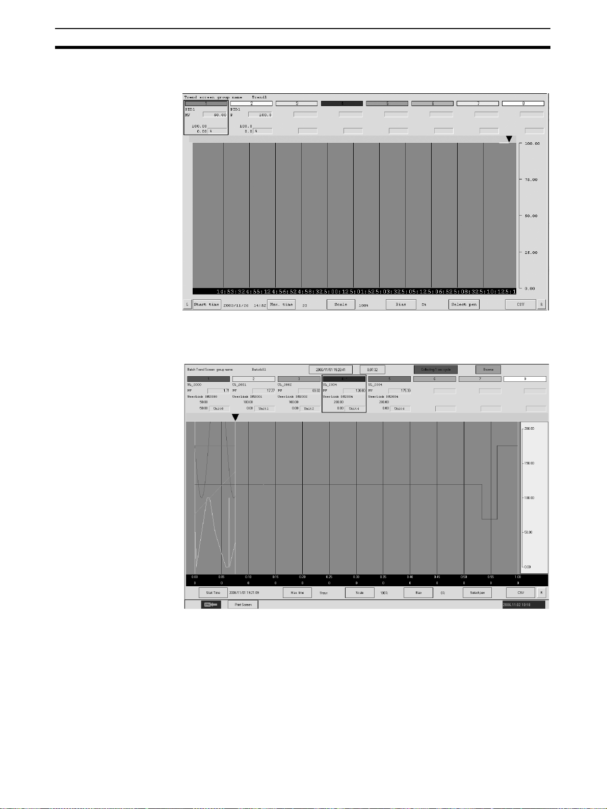
Trend Screens Display as an image changes due to the passage to time of the Control Block
PV, SP, MV, or other analog signals.
Batch Trend Screens Display a recorder image of the changes over time of the Control Block PV,
SP, MV, or other analog signals. Trend sampling is started and ended with tag
data (digital or analog) as the trigger.
6
Page 22
CX-Process Monitor Plus Section 1-1
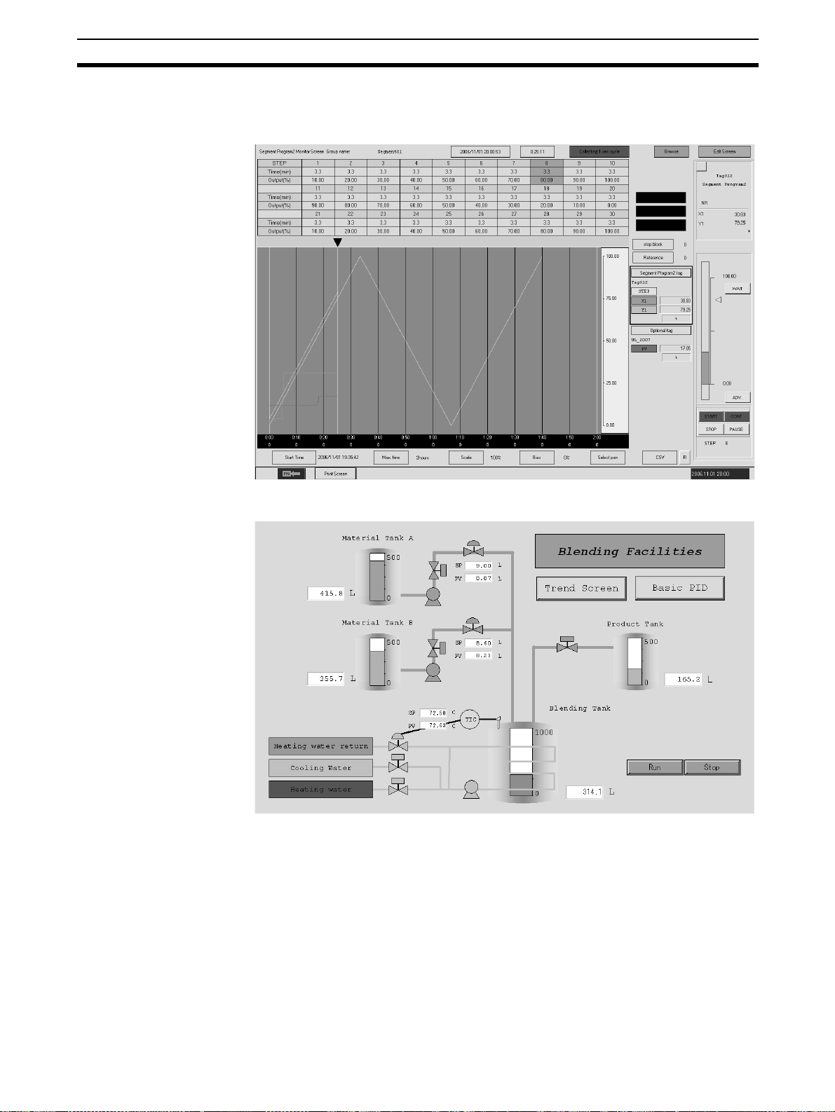
Segment Program 2
Screens
Display a recorder image of PV trends for Segment Program 2 (Block Model
157) set values. Segments can be set in table format while observing a time
axis graph.
Graphic Screens Use the screen to display the device status as a schematic.
7
Page 23
CX-Process Monitor Plus Section 1-1
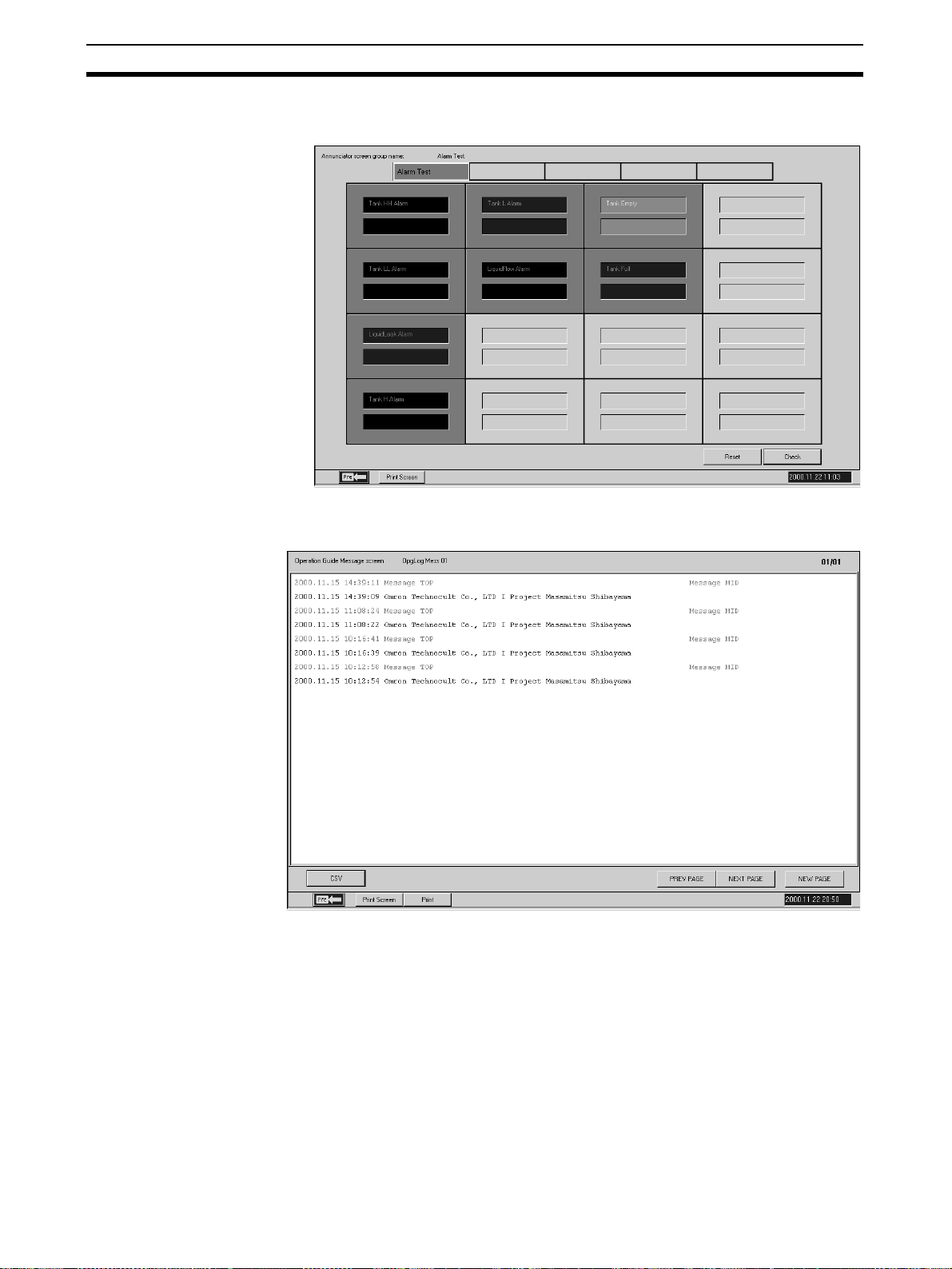
Annunciator Screens Use this screen to display comprehensively the status (mainly the alarm sta-
tus) of the contacts.
Operation Guide Screens Use this screen to display registered messages when the contact signal is
ON.
8
Page 24
CX-Process Monitor Plus Section 1-1
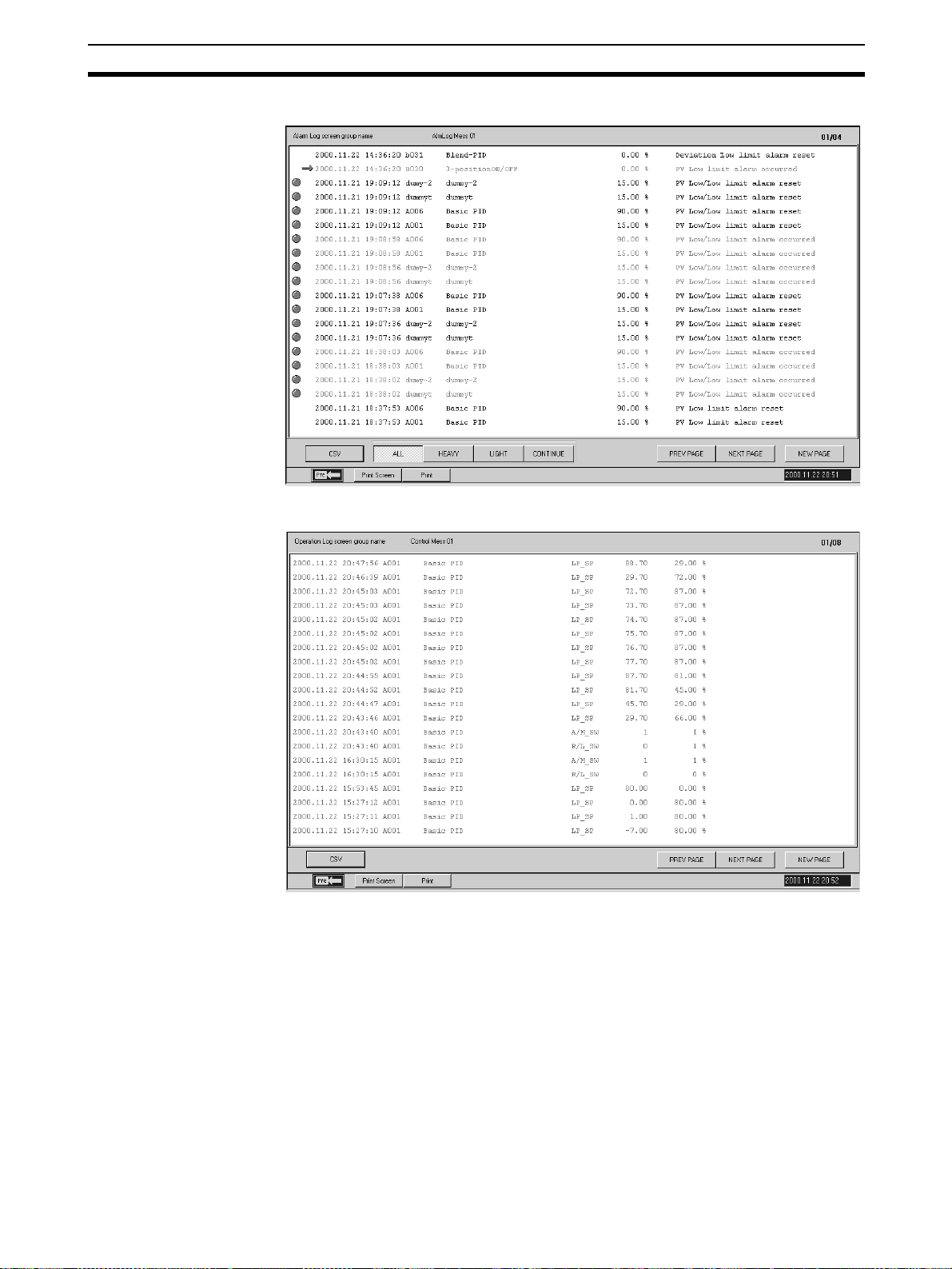
Alarm Log Screens Use this screen to display the alarm history.
Operation Log Screens Use this screen to display the operation history.
9
Page 25
CX-Process Monitor Plus Section 1-1
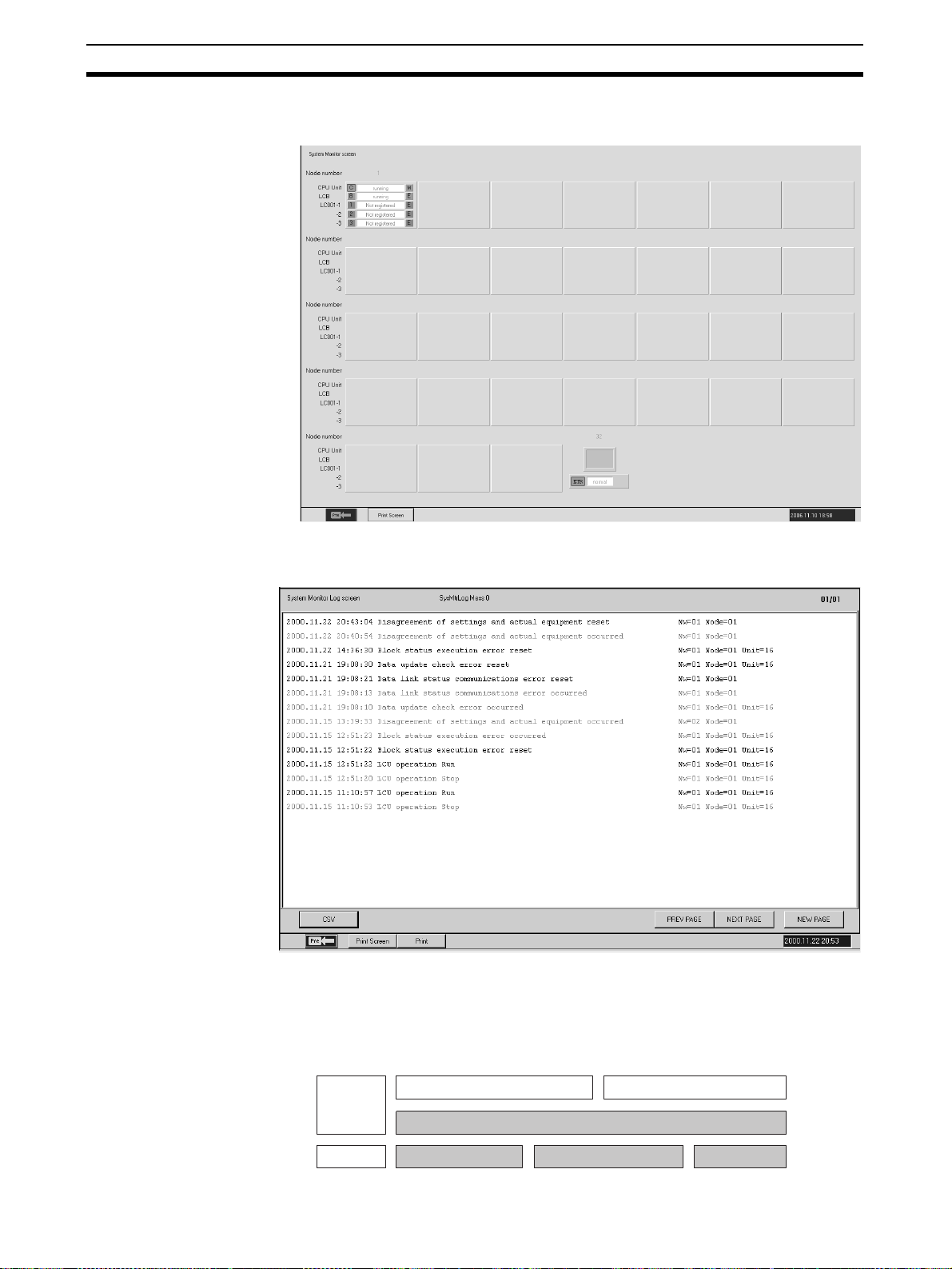
System Monitor Screens Use this screen to display the system status, and run/stop the Loop Control
Unit/Board.
System Monitor Log
Screens
Use this screen to display the run/stop history and Execution error history, and
to record the time at which they occurred.
1-1-3 CX-Process Monitor Plus System Requirements
FinsGateway As shown below, the CX-Process Monitor Plus uses the communications
driver FinsGateway (Embedded version) to communicate with the PLC (Programmable Controller) mounted to the Loop Control Unit/Board.
CX-Process Tool CX-Process Monitor Plus
Software
FinsGateway (Embedded version)
Hardware
RS-232C port
Controller Link
Support Board
Ethernet board
10
Page 26

CX-Process Monitor Plus Section 1-1
You can use any one of the FinsGateway (Embedded version) given below.
• Serial Unit driver
• Controller Link driver
• CLK (PCI) driver
• ETN_UNIT driver
Note 1. You cannot start CX-Process Monitor Plus if FinsGateway (Embedded ver-
sion) is not installed.
2. CX-Process (Monitor Plus and Tool) cannot use FinsGateway Version 1 as
a communications driver. Be sure to use Version 3 or later.
3. If CX-Programmer, CX-Protocol, CX-Motion, or other Support Software
(i.e., CX-Server communications software), or applications that use special serial drivers, are connected online, they use the same COM port, so
CX-Process (Monitor Plus and Tool) cannot connect online (i.e., initialize
serial communications) using the Host link (SYSWAY). First disconnect offline other Support Software or applications that use special serial drivers,
before reconnecting online (i.e., initializing serial communications) CXProcess. Conversely, while CX-Process is connected online (i.e., initializing serial communications), other Support Software that communicate using CX-Server cannot connect online.
4. You cannot install CX-Process and FinsGateway Version 1 on the same
IBM PC/AT or compatible.
5. If using Windows NT 4.0 as your OS, you must use Service Pack 6a or later.
6. Both FinsGateway Version 3 and Version 2003 (Embedded version) are
bundled with the CX-Process Monitor Plus software.
When using FinsGateway for the communications driver, install one of
these versions. The FinsGateway Runtime Version can also be used. If the
runtime version is already installed, it is not necessary to install the embedded version.
Set Network Address,
Node Address, and Unit
Address.
Note The CX-Process Monitor and CX-Process Monitor Plus use FinsGateway as
The network address, node address, and unit address for communications
between the CX-Process Monitor Plus and PLC are set using the CX-Process
Tool address settings (Settings/Network Settings).
the communications driver for connections with the PLC. When using the CXProcess Monitor or CX-Process Monitor Plus, always set FinsGateway as the
communications driver for the CX-Process Tool. If the CX-Server is set, the
CX-Process Monitor or CX-Process Monitor Plus will not be able to go online
with the PLC.
11
Page 27
CX-Process Monitor Plus Section 1-1
Register the Function
Blocks to Exchange Data
with the CX-Process
Monitor Plus.
Items to
monitor
Function
block data
Contact
signals
Analog
signals
Registrations and
connections
Only register the function blocks.
Register and connect
the function blocks.
Register and connect
the function blocks.
Register and connect the function blocks to exchange data with the CX-Process Monitor Plus. The following function blocks can be used depending on
the items to be monitored.
Loop Control Unit Loop Control Board
Send All Blocks block (Block Model 462)
and Receive All Blocks block (Block
Model 461)
Contact Distributor (Block Model 201) or Internal Switch (Block Model 209)
Input Selector block (Block Model 162) and Constant Generator block (Block Model
166)
Block to input analog signals from
the CX-Process Monitor Plus.
Main function blocks Block to output analog signals to
HMI settings in the System Common
block (Block Mode 000)
the CX-Process Monitor Plus.
Blocks to monitor function
block ITEM tags from the
CX-Process Monitor Plus.
Set CSV Tags and Tags for
CX-Process Monitor Plus.
1,2,3... 1. Register the Send All Blocks block (Block Model 642) and Receive All
Blocks to manipulate or display contacts
from the CX-Process Monitor Plus.
The CX-Process Monitor Plus uses tags set from the CX-Process Tool (Ver.
3.2 or higher) to read and write data in Loop Control Units/Boards. To use the
CX-Process Monitor Plus, therefore, CSV tags and tags for the CX-Process
Monitor Plus must be set.
Loop Control Units
Blocks block (Block Model 641).
2. Set tags as follows:
• Function block data: Set CSV tags.
• Individual contact signals: Set tags for Monitor Plus for the contacts in the
Internal Switch block (Block Model 209).
• Individual analog signals from LCU to computer: Set tags for Monitor Plus
for the analog signals in the Input Selection block (Block Model 162).
• Individual analog signals from computer to LCU: Set tags for Monitor Plus
for the analog signals in the Constant Generator block (Block Model 166).
12
Page 28
CX-Process Monitor Plus Section 1-1
Loop Control Boards
1,2,3... 1. Make the settings for the HMI in the System Common block (Block Model
000).
2. Set tags as follows:
• Function block data: Set CSV tags.
• Individual contact signals: Set tags for Monitor Plus for the contacts in the
Internal Switch block (Block Model 209).
• Individual analog signals from LCU to computer: Set tags for Monitor Plus
for the analog signals in the Input Selection block (Block Model 162).
• Individual analog signals from computer to LCU: Set tags for Monitor Plus
for the analog signals in the Constant Generator block (Block Model 166).
Note For both the Loop Control Unit and Loop Control Board, the follow-
ing function blocks must be created and connected separately to
enable monitoring and setting individual contact signals and individual analog signals (i.e., other than function block data).
• To monitor and set individual contact signals, contact signals must be
input/output using the Contact Distributor block (Block Model 201) and
Internal Switch block (Block Model 209).
• To monitor individual analog signals, analog signals must be output
from the Input Selection block (Block Model 162).
• To set individual analog signals, analog signals must be input to the
Constant Generator block (Block Model 166).
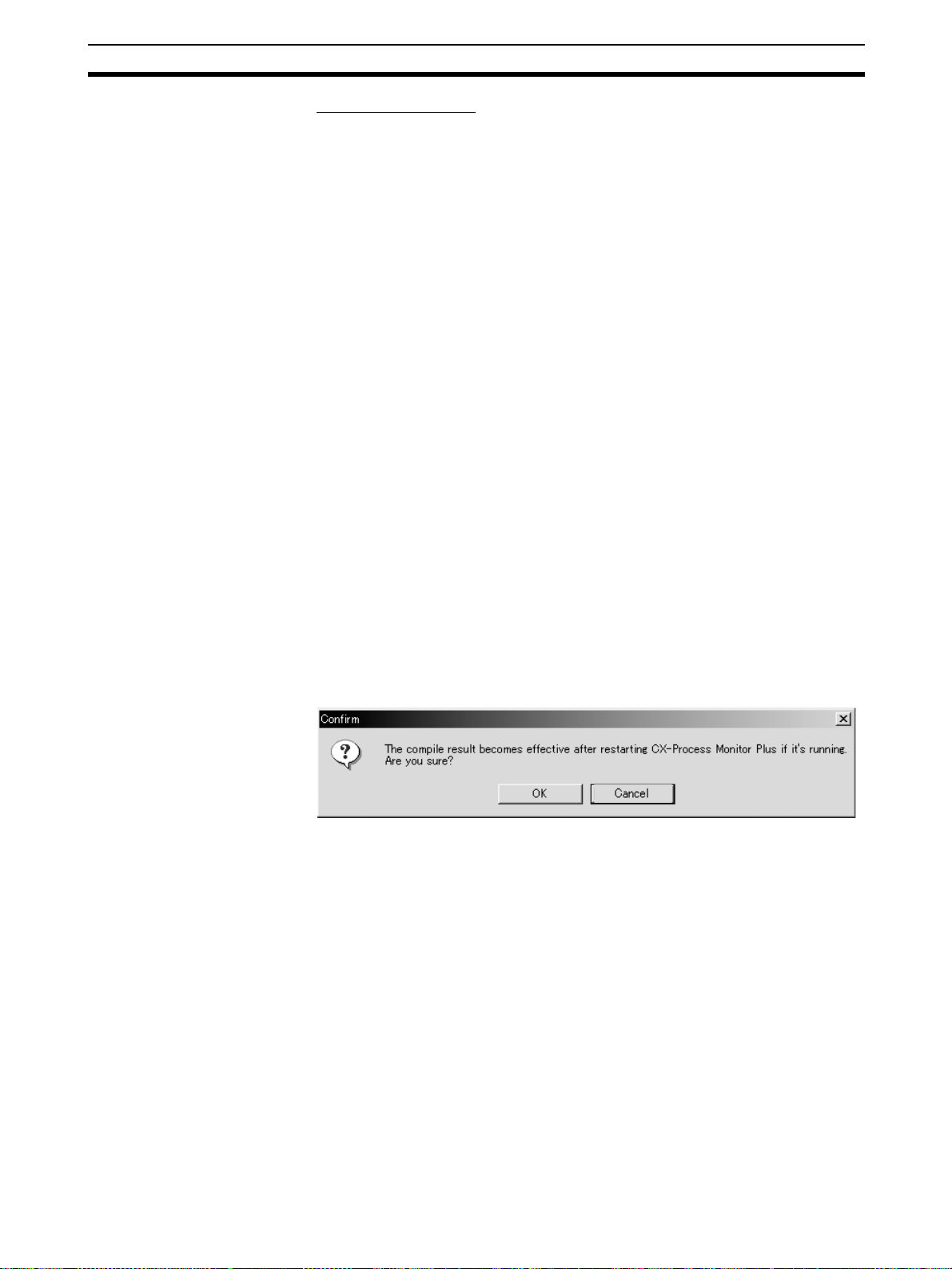
Compile the Tag File for
the CX-Process Monitor
Plus.
Note The following dialog box will be displayed if a tag file for Monitor Plus is output
Download Function Block
Data to the Loop Control
Unit/Board.
Compile the Monitor Tag
Files.
The tag file for Monitor Plus must be compiled (Execute – Create Tag File –
Monitor Plus Tag).
while the CX-Process Monitor Plus is running.
Tag information will not be updated if a tag file for Monitor Plus is output during CX-Process Monitor Plus operation. To update the tag file, restart the CXProcess Monitor Plus.
Download the function blocks.
Start the CX-Process Monitor Plus. In the Main Window, click the Run Button
or the Setup Button. The monitor tag files (mtagmst and mtagsubmst) will be
automatically generated based on the tag file for Monitor Plus (monitor.csv).
13
Page 29

CX-Process Monitor Plus Section 1-1
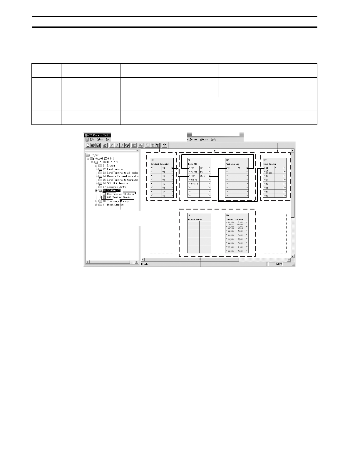
1-1-4 Relationship to CX-Process Tool
Tag Names As shown earlier in CX-Process Monitor Plus Conditions of Use, if monitoring
or operating Function Blocks using CX-Process Monitor Plus, you must first
perform the following steps using CX-Process Tool.
1,2,3... 1. Set the network address, node address, and unit address.
2. Register the blocks for which data is to be exchanged with the CX-Process
Monitor Plus.
3. Set the CSV tags and tags for Monitor Plus.
4. Generate the tag file for Monitor Plus.
5. Download the function block data to the Loop Control Unit/Board.
6. Compile the monitor tag file.
CX-Process Monitor Plus handles all items allocated tag names as one string.
CX-Process Monitor Plus does not differentiate which Function Block was
used to specify the tag names.
ITEM Settings Function block ITEMs are set as shown in the following table. The CX-Process
Tool is normally used to set initial data S and the CX-Process Monitor Plus is
normally used to set operation data O.
CX-Process Tool
data classification
Initial settings S Initial setting parameter
Operation data O Operation parameters
Type ITEM Example: PID Block CX-Process
for each function block
for each function block
Note Initial settings O and operation data S classifications are displayed on ITEM
Setting Screens of the CX-Process Tool. For details on the ITEMs set each
function block, refer to the Function Block Reference Manual.
Example
ITEM type ITEM Contents R: Read, W: Write,
Parameter 004 Operation cycle (s) R/W (S) ---
Parameter 008 High/Low alarm R/W (O) R/W
012 Hysteresis set value R/W (S) ---
Parameter 023 Local SP set value R/W (O) R/W
024 SP set method (Initial setting)
0: Local, 1: Remote/Local
Forward/Reverse direction,
SP setting method, compensation method, etc.
Example: PID Block SP,
alarm settings, PID constants, etc.
R/W (S) R
Tool
Set Cannot be set
Set in special
cases
R/W: Read/write,
---: R/W disabled
r, t/w: CX-Process Tool
operation monitor/Operation
monitor read and write
(S): Initial setting,
(O): Operation data
CX-Process
Tool
CX-Process
Monitor Plus
Set
CX-Process
Monitor Plus
14
Note Analog values are normally set with the CX-Process Monitor Plus. They can
be set with the CX-Process Tool provided that they are in percentage increments between 0% and 100%. Scaling engineering units cannot be set with
the CX-Process Tool.
Page 30

CX-Process Monitor Plus Section 1-1
1-1-5 Relation between Screens and Function Blocks
The relation between screens and function blocks is shown below.
Userdefined
screens
System
screens
Screen Loop Control Unit: Register Send All
Overview
Screen
Control
Screens
Tuning
Screens
Trend
Screens
Batch Trend
Screen
Segment
Program 2
Screen
Graphic
Screens
Annunciator
Screens
Operation
Guide
Screens
System
Monitor
Screens
Alarm Log
Screens
Operation
History
Screens
System
Monitor Log
Screens
Blocks and Receive All Blocks blocks
Loop Control Boards: Make HMI settings
in the System Common block
--- --- --- ---
Basic PID, Advanced PID, Blended PID
(Block Model 013), Batch Flowrate Capture
(Block Model 014), Indication and Setting,
Indication and Operation, Ratio Setting,
Indicator, 2-Position ON/OFF, 3-Position
ON/OFF, High/Low Alarm, Segment Program 2, ON/OFF Valve Manipulator, Motor
Manipulator, Reversible Motor Manipulator,
Motor Opening Manipulator, Timer, Counter
Segment Program 2 --- --- ---
Basic PID, Advanced PID, Blended PID
(Block Model 013), Batch Flowrate Capture
(Block Model 014), Indication and Setting,
Indication and Operation, Ratio Setting,
Indicator, 2-Position ON/OFF, 3-Position
ON/OFF (PV, SP, MV only), Segment Program 2, ON/OFF Valve Manipulator, Motor
Manipulator, Reversible Motor Manipulator,
Motor Opening Manipulator
Segment Program 2 Can be desig-
Same tag ITEMs as for Control screens. Analog signal
Same tag ITEMs as for Control screens. --- Contact signal
--- --- Contact signal
--- --- --- ---
Contacts for which alarms were automatically allocated when registering tags
--- --- --- ---
--- --- --- ---
Input Selector
block (Block
Model 162)
Analog signal
or analog value
parameters
Analog signal
or analog value
parameters
nated as
expansion measurement tags
or analog value
parameters
--- Contacts for
Internal Switch
block (Block
Model 209)
Contact signal
or contact
parameters
Contact signal
or contact
parameters
Can be designated as
expansion measurement tags
Contact signal
or contact
parameters
or contact
parameters
or contact
parameters
which alarms
were automatically allocated
when registering tags
Constant
Generator
block (Block
Model 166)
Analog output
Analog output
Can be designated as
expansion measurement tags
Analog output
---
---
---
15
Page 31

CX-Process Monitor Plus Section 1-1
1-1-6 CX-Process Monitor Plus Software Specifications
CX-Process Monitor Plus Specifications
Item Descriptions
Product name CX-Process Monitor Plus
Model WS02-LCMC1-EV2
Applicable PLC-series CS/CJ-series
Applicable Unit Loop Control Unit Ver. 2.0 or later
Applicable
computer
Required software FinsGateway (One of the following must be installed according to the commu-
Connecting
method
Loop Control Unit/Board data specification method
Offline operation functions Prepare user configuration screens for use in the online operation screen.
Personal computer IBM PC/AT or compatible
CPU Min. required: Pentium MMX233 MHz or faster, Recommended: Celeron
OS Microsoft Windows NT 4.0 (Service Pack 6a or higher), Windows 2000 Profes-
Memory Min. required: 128 Mbytes, Recommended: 256 Mbytes or more
Hard disk drive Min. required: 650 Mbytes of free space, Recommended: 800 Mbytes or more
Monitor Min. required: XGA, Recommended: XGA or higher, min. 1024 × 768 dots, 256
CD-ROM drive At least one
Mouse Recommended: Microsoft mouse or compatible pointing device
Printer Any printer supported by Microsoft Windows
Sound board 1 board
Connection with CPU Unit
(or Serial Communications
Board/Unit)
Connection via Controller
Link
Connection via Ethernet Using Fins-
Loop Control Board
Process-control CPU Unit
Loop-control CPU Unit
400 MHz or faster
sional (Service Pack 4 or higher), Windows XP Professional (Operation is not
supported on Windows 95, 98, or ME.)
of free space
colors
nications method with the PLC.)
Serial Unit driver (Host Link)
Controller Link driver (Controller Link)
CLK (PCI) driver (Controller Link, PCI bus)
ETN_UNIT driver (Ethernet)
Using FinsGateway
Serial Unit
version
Using FinsGateway CLK
(PCI) Driver
Using FinsGateway
Controller
Link driver
Gateway
ETN_UNIT
driver
CSV tags and tags for Monitor Plus (CSV monitor tags) are set using the CXProcess Tool. These tags are used to specify Loop Control Unit/Board data.
The computer is connected to the CPU Unit peripheral ports or
integrated RS-232C port, or RS-232C port of the Serial Communications Unit. (Only a 1:1 connection is possible.)
– Connector cable:
When connecting to the CPU Unit peripheral ports: Model
CS1W-CN@@@ (2 m, 6 m)
When connecting to the CPU Unit’s RS-232C port: Model
XW2Z@@@-@ (2 m, 5 m)
– Communications protocol with PLC: Host Link (not supported
on Peripheral bus)
Install the driver in a computer equipped with a Controller Link
Support Board (PCI slot) to support communications between
the computer and PLCs equipped with a Controller Link Unit.
Install the driver in a computer equipped with a Controller Link
Support Board (ISA slot) to support communications between
the computer and PLCs equipped with a Controller Link Unit.
Install the FinsGateway ETN_UNIT driver on the computer on
which an Ethernet board is mounted to enable to enable communications with the PLC on which the Ethernet Unit is
mounted.
16
Page 32

CX-Process Monitor Plus Section 1-1
Item Descriptions
Online
operation
functions
User Configuration
screen
Overview
screen
Control
screen
Tuning
screen
Trend
screen
Place buttons for progressing to the Control screen, Trend screen and other
screens. 4 columns and 8 lines are displayed on each screen (max. 32
screens).
Control blocks such as the PID blocks and Indication blocks, and some Operation blocks are displayed for up to 8 loops in a single screen in the form of a
field device. The maximum number of screens is 400.
This screen displays the Set Point, PV and MV numeric values, displays PV as
a bar graph, and can be used for changing Set Point, MAN and other setting
values. The color of bar graphs changes when an alarm occurs.
You can progress to the Tuning screen from the Control screen.
Fine tuning according to the degree specified by the user is possible for PID
constants.
This screen is for setting P, I, D parameters in Control blocks such as the PID
blocks, and for setting alarm setting values. PV, Set Point and MV can be tuned
while their trends are monitored. The maximum number of screens is 3200.
Run stop/stop cancellation are possible on each function block.
Note Only the Control block that is designated as the source at the 1-Block
The analog signals output from each function block tag ITEM are collected at
fixed intervals and saved to a file. If necessary, up to 8 analog signals can be
displayed on one screen in the form of a multi-dot recorder.
Data collected
(logger function)
Data display Horizontal (time) axis: 2, 4, 8, 12 and 24 hour time units
Send Terminal to Computer block can be registered.
Real time trend
10, 20, 50, 100, or 300
hours of data is saved at 1,
2, 5, 10, or 30-second intervals for up to 480 tags.
Historic trend
30, 150, 300, 900, or 1,800
days of data is saved at 1,
5, 10, 30, or 60-minute
intervals for up to 960 tags.
Vertical (8-point common) axis: Graduation can be
Data is displayed from the time when the specified display
start time is reached.
Display color: red, yellow, green, blue, magenta, purple,
cyan, white
Data can be saved in CSV
format either using button
commands, or automatically at a set interval (every
1, 2, 3, 4, 6, 8, 10, 12, 18,
20, 24, 48, 72, 96, 120, or
240 hours)
can be scrolled
enlarged by a factor or 1,
2, 5 and 10.
17
Page 33

CX-Process Monitor Plus Section 1-1
Item Descriptions
Online
operation
functions
User Configuration
screen
Batch Trend
Screen
Segment
Program 2
Screen
The analog signals output from each function block tag ITEM are collected at
fixed intervals when tag data conditions are satisfied, and the data is automatically saved. Data can be displayed in combination with past data.
Data collection Four hours or ten days of
data is saved at 1-second
or 1-minute intervals for up
to 960 tags.
Data display Horizontal (time) axis: The following time units can be
Vertical (8-point common) axis: Gradation can be
When a display start time is specified, data is displayed
from that time.Display color: Red, yellow, green, blue,
magenta, purple, cyan, white
Displays PV trends for Segment Program 2 (Block Model 157) set values. Segments can be set in table format while observing a time axis graph.
Data collection 3, 30, or 180 days of data is
saved at 1-, 10-, or 60-second intervals.
Data display Horizontal (time) axis: 2, 4, 8, 12, 24, 72 hour time incre-
Vertical axis: Gradation can be enlarged by a factor of
1, 2, 5, or 10.
When a display start time is specified, data is displayed
from that time.
Display color: Yellow, light blue, green, purple
Data can be manually
saved in CSV format by button operations or automatically saved at the
completion of each batch.
Past data can be automatically saved in binary format.
scrolled.
1, 2, 4, 6, 8, 12, 24, 36, 48, and
72 hours; 7 or 10 days
enlarged by a factor of
1, 2, 5, or 10.
Data can be manually
saved in CSV format by button operations or automatically saved with each batch
completion.
Past data can be automatically saved in binary format.
ments can be scrolled.
18
Page 34

CX-Process Monitor Plus Section 1-1
Item Descriptions
Online
operation
functions
User Configuration
screen
System
Fixed screen
Graphic
screen
Annunciator
screen
Operation
Guide
Screen
Alarm Log
screen
Operation
Log screen
System
Monitor
screen
System
Monitor Log
screen
Graphic elements representing plant process control can be pasted to Graphic
Screens from a library. These elements can be used to display changes in
plant status. Up to 200 Graphic Screens can be created.
• Library Figures and Image Elements
Text displays, straight lines, rectangles, rectangle with round corners,
ellipses, polygons, images
• Library Functional Objects
• Fixed Graphic Display Elements:
Text, instruments, thermometers, transmitters, orifices
• Changeable Graphic Display Elements:
Analog displays: Bar graph displays, numeric displays, tanks
Analog settings: Numerical settings
Contact display: Pumps, valves, pipes
Contact operation: Switches
• Elements for Screen Display:
Screen jump elements
FP switch (faceplate popup) elements
• Individual graphic screens can be saved as files or read.
• Multiple graphic elements can be grouped and saved as files or read.
This screen notifies the operator of alarms or errors that occur by changing the
display color and emitting sound. At the same time, a 32-character message is
displayed over two lines on screen elements.
A total of 16 screen elements (4 columns × 4 lines) can be displayed on each
screen. The maximum number of screens is 5.
This screen displays pre-registered 128-character messages over two lines
together with the date of occurrence when the specified internal switch is set to
ON.
Max. number of registerable messages: 1000, Number of display colors: 16
Up to 1000 messages are displayed in a single screen.
Output possible in CSV format.
A record of alarms (time of error occurrence, tag name, PV or MV current
value at occurrence, alarm type, etc.) that occur and that are input from the
Control and Alarm blocks is saved and displayed as a list later.
Up to 1000 alarm messages are displayed in a single screen.
Output possible in CSV format.
A record of operations using graphic screen data and switch objects and
changes made to ITEM data in the Loop Control Unit/Board in the Control or
Tuning Screen can be saved and later displayed as an operation log. The operation log includes the date and time of change, tag name, original ITEM data
setting, new ITEM data setting, etc.
Up to 1000 operation messages are displayed in a single screen.
Output possible in CSV format.
This screen displays the Loop Control Unit/Board system error information.
This screen displays a log of the run/stop history and a history of execution
errors that occur on the Loop Control Unit/Board together with the date of
occurrence.
Output possible in CSV format.
The Loop Control Unit/Board does not itself have HMI functionality. To monitor
function block operation status, it is thus necessary to connect and use the
CX-Process Monitor Plus.
19
Page 35

CX-Process Monitor Plus Section 1-1
1-1-7 CX-Process Monitor Plus Setting and Monitoring Capabilities
The data that can be set and monitored using the CX-Process Monitor Plus is
listed in the following table.
Item Loop Control Unit Loop Control Board
Function block data Control Blocks:
Basic PID (Block Model 011), Advanced PID (Block Model
012), Blended PID (Block Model 013), Batch Flowrate Capture
(Block Model 014), Indication and Setting (Block Model 031),
Indication and Operation (Block Model 032), Ratio Setting
(Block Model 033), Indicator (Block Model 034), 2-position
ON/OFF (Block Model 001), and 3-position ON/OFF (Block
Model 002)
Operation Blocks:
High/Low Alarm (Block Model 111), Segment Program 2
(Block Model 157), ON/OFF Valve Manipulator (Block Model
221), Motor Manipulator (Block Model 222), Reversible Motor
Manipulator (Block Model 223), Motor Opening Manipulator
(Block Model 224), Timer (Block Model 205) and Counter
(Block Model 208)
Contact signals Contact signals through Contact Distributor (Block Model 201)
Analog
signals
Sent to
Monitor Plus
Set from
Monitor Plus
+ Internal Switch (Block Model 209)
Analog signals through Input Selector (Block Model 162)
Analog signals through Constant Generator (Block Model 166)
The following items must be set in advance using the CX-Process Tool.
Item Loop Control Unit Loop Control Board
1. Register the function
blocks used for data
exchange.
2. Set the tag names. Function Block Data:
3. Create the monitor tag file. Start the CX-Monitor Plus and click the Run or Setup Button.
Function block data
exchange
Contact signal data
exchange
Analog signal data
exchange
Receive All Blocks (Block Model
461) and Send All Blocks (Block
Model 462)
Contact Distributor block (Block Model 201) + Internal Switch block
(Block Model 209)
Input Selector block (Block Model 162) and Constant Generator
block (Block Model 166)
CSV tags are set in the CX-Process Tool by selecting the function
blocks and then selected Settings – Tag Setting – CSV Tags.
Contact Signals:
tags for Monitor Plus are set for each contact in the Internal Switch
blocks. The function blocks are then selected, the right mouse button
clicked, and Tag Setting – Monitor Plus Tag is selected.
Analog Signals:
tags for Monitor Plus are set for each analog signal in the Variable
ITEM Setting and Constant Generator blocks. The function blocks
are then selected, the right mouse button clicked, and Tag Setting –
Monitor Plus Tag is selected.
HMI functions in the System
Common block (Block Model
000)
Note Using CX-Process Monitor Plus, you can monitor and set only the data given
above to which tag names have been allocated. Also, be sure to use CX-Process Tool to make tag name settings.
20
Page 36

CX-Process Monitor Plus Section 1-1
1-1-8 Files Created Using CX-Process Monitor Plus
The following data can be created using the CX-Process Monitor Plus
Data type Contents
Graphic screen data
(filename extension: grf)
Object data
(filename extension: itm)
Graphic screen data, created for each screen.
Grouped object data (functional objects, figures,
images), created when a group file is saved. (Does
not include jump elements or FP switch elements.)
1-1-9 Version Upgrade
The CX-Process Monitor Plus has been upgraded from version 1.0 to version
2.0. The following table lists the contents of the version upgrade.
Item Previous (version 1.0) New (version 2.0)
Startup method There were two modes: Engineer Mode
Monitor display Maximum size: XGA 1,024 × 768 Individual monitor screens can be dis-
Segment Program 2 Screen No Yes
Batch Trend Screens No Yes
Trend
Screens
Graphic
Screens
Data collection cycle and
maximum retention period
for realtime trends
Data collection cycle and
maximum retention period
for historical trends
Graphic screen saving and
reading
and Operator Mode.
• Setup (Engineer Mode)
Start Button → Engineer Button →
Setup Button → Password input
• Operation
Start Button → Operator Button
Collection cycle: 10 s
Maximum retention period: 12 hours
Collection cycle: 1 min
Maximum retention period: 10 days
Yes (No filename extension) Yes (Filename extension: GRF)
Startup has been divided into setup and
operation.
• Setup
Setup Button → Password input →
Run Button
• Operation
Run Button
played on the entire desktop.
• PV trends for values set in the Segment Program 2 Monitor Screen are
displayed.
• Collection cycle: 1, 10, or 60 s
Maximum retention period:
3, 30, or 180 days, past data automatically saved, or CSV data automatically
saved
• Segments can be set in table format on
the Segment Program 2 Edit Screen.
• Past data can be read.
• Trend function that can start or end col-
lecting with tag data (contact or analog) as a trigger.
• Collection cycle: 1 min or 1 s
Maximum retention period: 10 days, 4
hours, past data automatically saved,
or CSV data automatically saved
• Data can be overlapped with past data.
Collection cycle: 1, 2, 5, 10, or 30 s
Maximum retention period: 10, 20, 50,
100, or 300 hours
Collection cycle: 1, 5, 10, 30, or 60 min
Maximum retention period: 30, 150, 300,
900, or 1,800 days
21
Page 37

CX-Process Monitor Plus Section 1-1
Item Previous (version 1.0) New (version 2.0)
Graphic
screen
objects
Function
objects
Figures
and
images
Individual
graphics
objects
Jumps (screen
call) objects
FR switch
(face plate
popup) objects
Figures No Yes
Images No Objects are provided for displaying
Grouping No Functional objects, figures and images
Displaying/hiding according
to tag values
Flashing
according to
tag values
Color changes
according to
tag values
Image
changes
according to
tag values
Full color
settings
Font specifications
Alignment and
fine position
adjustment
No Yes
No Yes
(Text display, straight lines, rectangle,
rectangles with round corners, ellipses,
and polygons) Color changes, displaying/hiding, and flashing can be enabled
by allocating tags.
images (BMP or JPEG) in frames rectangles. Color changes, displaying/hiding, and flashing can be enabled by
allocating tags.
(except for jump objects and FP switch
objects) can be grouped, and groups
can be cut, moved, deleted, saved in
files, or loaded from files (filename
extension: ITM).
No Yes
(Tanks, pipes, pumps, valves, meter
bars, data, parts, switches, and text
boxes)
Note: Also enabled for figures (text dis-
play, straight lines, rectangles,
rectangles with round corners,
ellipses, and polygons) and
images.
No Yes
(Tanks, pipes, pumps, valves, meter
bars, data, parts, switches, and text
boxes)
Note: Also enabled for figures (text dis-
play, straight lines, rectangles,
rectangles with round corners,
ellipses, and polygons) and
images.
No Yes
(Text display, straight lines, rectangles,
rectangles with round corners, ellipses,
and polygons)
No Yes
(Images)
No
(16 colors)
Fonts cannot be specified Fonts can be specified.
Vertical and horizontal alignment of
multiple objects, and alignment to grid
lines
Ye s
(Tanks, meter bars, data, parts,
switches, and text boxes)
The following functions have been
added: Arranging multiple objects with
even spacing, and fine adjustment of
positions (using the cursor) when moving objects.
22
Page 38

Basic Operating Procedure Section 1-2
Item Previous (version 1.0) New (version 2.0)
Graphic
screen
objects
Logs CSV file output (operation
Operation
guide
messages
Starting external applications and
starting/resetting from external applications
Confirmation message when exiting
the CX-Process Monitor Plus
Data
objects
Switch
objects
Data and
text box
objects
Data and
switch
objects
Number of simultaneous
Graphic Builder screens for
editing
logs, alarm logs, operation
logs, and system monitor
logs)
Number of operation guide
messages registered
Data input
range checks
Text s tr in g
positions
Text s tr in g
specification
Background
color transparency
Operation log No Yes
No Yes
(Upper and lower limits can be checked
for inputs.)
Left justified and centered vertically. The following are possible: Left justified,
horizontally centered, right justified, top
aligned, vertically centered, and bottom
aligned.
Only ON, OFF, START, and STOP can
be specified.
No Yes
One screen only Multiple Graphic Builder screens can be
Single lines are output without separating individual items.
100 max. 1,000 max.
A portion of the CX-Process Monitor
Plus display remains.
Exits with no message. A dialog box is displayed to confirm
Any text string can be specified.
displayed simultaneously for editing, and
objects can be copied between screens.
Each item can be separated in the output (making later analysis easier).
The CX-Process Monitor Plus Window
is completely cleared and the external
application is started. (The CX-Process
Monitor Plus runs in the background and
collects data.)
The CX-Process Monitor Plus can be
reset by starting the execution file from
an external application.
whether the Monitor Process is to be
ended during execution.
Note The CX-Process Monitor Plus does not support Loop Control Units earlier
than version 2.0.
1-2 Basic Operating Procedure
This section explains the procedure up to monitoring using CX-Process Monitor Plus.
1,2,3... 1. Install CX-Process Monitor Plus. (Refer to Section 2 Setup.)
• Install CX-Process Monitor Plus.
2. Make Settings and Transfer Using CX-Process Tool. (Refer to the CX-Pro-
cess Tool Operation Manual (W372).)
a. Set the network address, node address, and unit address (Settings –
Network).
b. Register and connect the function blocks that exchange data with the
CX-Process Monitor Plus.
c. Set the CSV tags and the tags for Monitor Plus.
23
Page 39

Basic Operating Procedure Section 1-2
• CSV tags: Settings – Tag Setting – CSV Tag
• Tags for Monitor Plus: Settings – Tag Setting – Monitor Plus Tag
d. Generate the tag file for Monitor Plus: Execute – Create Tag File –
Monitor Plus Tag
e. Download the function block data to the Loop Control Unit/Board.
f. Compile the monitor tags. Start the CX-Process Monitor Plus and click
the Setup Button.
g. Enter password.
Note (a) If the above steps are not performed using CX-Process Tool, you
cannot monitor using CX-Process Monitor Plus.
(b) The network address, node address, and unit address settings
made with CX-Process Tool are also used by the CX-Process
Monitor Plus.
3. Configure the Screen Using CX-Process Monitor Plus. (Refer to Section 4
Screen Configuration.)
• Design the monitor system using CX-Process Monitor Plus.
• Create and register the Control screens, Trend screens, Graphic screens,
and Annunciator screens on Overview screens.
• When registering, specify on the screen the Loop Control Unit/Board data
by selecting the tags (CSV tags and tags for Monitor Plus) set using CXProcess Tool.
• Set the communications conditions with the PLC using the system monitor setting window (if using serial communications).
Perform the following procedure.
a. Select Omron – CX-Process Monitor Plus – CX-Process Monitor
Plus from the Windows Start Menu.
b. Click the Setup Button in the Main Window.
c. Enter password.
d. Click the System Monitor Builder Button in the Setup Dialog Box,
and make settings using the System Monitor Setting Window.
e. Click the Graphic Builder Button in the Setup Dialog Box, create the
Graphic Screen Create Window (including tag name specifications),
and save.
f. Click the CRT Builder Button in the Setup Dialog Box, and register the
screen using the Builder Window (including Tag name specifications).
g. From the Builder Window Settings menu, select Save, and then click
the OK Button.
4. Check Screen Configuration Using CX-Process Monitor Plus. (Refer to 5-
7 Checking Configurations.)
• Check if you can monitor the Loop Control Unit/Board using the configured screen.
• Start FinsGateway Serial Unit communications according to the communications conditions set using the System monitor setting window by starting the monitoring process (i.e., start FinsGateway Controller Link and
Ethernet manually).
Perform the following operation.
a. Click the Setup Button in the Main Window.
b. Enter password.
24
Page 40

Basic Operating Procedure Section 1-2
c. In the Setup Dialog Box, click the Run Button (to start the monitoring
process for the configured screen, and to start communications).
d. Select the screens using the Overview Screen, and check that each
function is operating normally.
5. Start the Monitor Operation to monitor the Loop Control Unit/Board. (Refer
to Section SECTION 4 Monitor Screen Functions and Operations for de-
tails.)
Perform the following operation.
a. Click the Run Button in the Main Window.
b. Click the screens using the Overview Screen.
25
Page 41

Basic Operating Procedure Section 1-2
26
Page 42

This section describes installing the CX-Process and connections to the PLC.
2-1 Installation. . . . . . . . . . . . . . . . . . . . . . . . . . . . . . . . . . . . . . . . . . . . . . . . . . . . 28
2-1-1 Before Installing FinsGateway . . . . . . . . . . . . . . . . . . . . . . . . . . . . . 29
2-1-2 Installing FinsGateway . . . . . . . . . . . . . . . . . . . . . . . . . . . . . . . . . . . 31
2-1-3 Uninstalling the CX-Process Monitor/Monitor Plus Version 1 . . . . 37
2-1-4 Installing CX-Process Monitor Plus . . . . . . . . . . . . . . . . . . . . . . . . . 38
2-1-5 Converting CX-Process Monitor Plus Data . . . . . . . . . . . . . . . . . . . 41
2-1-6 Converting Data from CX-Process Monitor. . . . . . . . . . . . . . . . . . . 43
2-1-7 CX-Process Monitor Plus Conversion Specifications . . . . . . . . . . . 46
2-2 Connecting the PLC . . . . . . . . . . . . . . . . . . . . . . . . . . . . . . . . . . . . . . . . . . . . 47
2-2-1 Connecting via Host Link. . . . . . . . . . . . . . . . . . . . . . . . . . . . . . . . . 47
2-2-2 Connecting through a Controller Link Support Board . . . . . . . . . . . 49
2-2-3 Connections via Ethernet . . . . . . . . . . . . . . . . . . . . . . . . . . . . . . . . . 49
SECTION 2
Setup
27
Page 43

Installation Section 2-1
2-1 Installation
Install the CX-Process Monitor Plus using the following procedure.
Install FinsGateway, Embedded Version.
(See sections 2-1-1 and 2-1-2)
Are CX-Process
Monitor and Monitor
Plus Version 1 already
installed?
New
installation
Ye s Ye s
No
Update
(Previous data will not
be used.)
(Screen configuration data
and trend information will
be lost.)
Is CX-Process
Monitor and Monitor
Plus Version 1 data to
be used with Monitor
Plus Version 2?
Uninstall the CX-Process Monitor
and Monitor Plus Version 1.
(See section 2-1-3)
Install CX-Process Monitor Plus Version 2. (See section 2-1-4.)
What is the version
of the CX-Process
Monitor and Monitor
Plus data?
CX-Process Monitor
Plus Version 1
Convert CX-Process Monitor Plus Version
1 data (See section 2-1-5)
Move the CX-Process Monitor Plus
Version 1 database.
Uninstall CX-Process Monitor Plus
Version 1. (See section 2-1-3)
Convert the CX-Process Monitor Plus
Version 1 data. (See section 2-1-5.)
Convert the CX-Process Monitor Plus
Version 1 database (using the Trend
Database Conversion Utility).
CX-Process Monitor
Convert the CX-Process Monitor data.
(See section 2-1-6.)
Reset to CX-Process Monitor Plus
tags all of the monitor tags set using
the CX-Process Tool.
Move the CX-Process Monitor
database.
Uninstall the CX-Process Monitor.
(See section 2-1-3.)
Convert the CX-Process Monitor data.
(See section 2-1-6.)
Convert the CX-Process Monitor (using
the Trend Database Conversion Utility).
28
Copy the data that was converted.
Redo the Graphic Screen data settings
(if Graphic Screens are being used).
Copy the data that was converted.
Redo the Graphic Screen data settings
(if Graphic Screens are being used).
Reallocate the reset tags for CXProcess Monitor Plus Version 2 on the
control and graphic screens.
Note 1. This software must be installed on an computer using Windows NT 4.0,
2000, or XP as its OS. It will not operate on Windows 95, 98, or Me.
2. Be sure to install FinsGateway Embedded before installing CX-Process
Monitor Plus. You cannot install CX-Process Monitor Plus first.
3. You cannot start CX-Process Monitor Plus if FinsGateway Embedded is
not installed.
4. If connecting CX-Process online using a PLC and Host Link, you cannot
install and use CX-Process on the same computer as FinsGateway Version 1.
Page 44

Installation Section 2-1
2-1-1 Before Installing FinsGateway
To use the CX-Process Monitor Plus software, the communications driver
(FinsGateway) must be installed in the computer in which the CX-Process
Monitor Plus software is installed.
FinsGateway
Versions
Selecting the
Communications Driver
Note 1. Supported for CX-Process Monitor Plus only with Windows NT 4.0 and
Both FinsGateway Version 3 and Version 2003 (Embedded version) are bundled with the CX-Process Monitor Plus software. When using FinsGateway for
the communications driver, install one of these versions.
The FinsGateWay Runtime version can also be used. If the Runtime version
is already installed, it is not necessary to install the Embedded version.
The CX-Process Monitor Plus software supports the following communications drivers.
• FinsGateway Ver. 3.12
• FinsGateway Ver. 2003
Select the communications driver to install according to the user's application.
The following tables show the main factors to use in selecting the driver.
OS
Driver OS
Windows NT 4.0
(See note 1.)
FinsGateway Ver. 3.12 Supported Supported Supported
FinsGateway Ver. 2003 Not supported Supported Supported
Service Pack 6a.
2. Supported for CX-Process Monitor Plus only with Windows 2000 Professional and Service Pack 4.
3. Supported for CX-Process Monitor Plus only with Windows XP Professional.
Windows 2000
(See note 2.)
Windows XP
(See note 3.)
Communications
Driver Communications method
FinsGateway Ver. 3.12 Not supported Not supported
FinsGateway Ver. 2003 Supported Supported (See note.)
Note When duplex Ethernet is used in the computer, the difference software is
stored in the following folder:
<CD-ROM drive>:\Fgw2003\Duplex\FgwEtnUpdate200301\setup.exe.
Items to Check before
Installing
FinsGateway
If a FinsGateway version earlier than Version 2 is already installed:
Start the procedure from Step 1: Backing Up the FinsGateway Settings.
Installing FinsGateway for the First Time:
Start the procedure from Step 4: Internet Explorer Installation.
Steps to Perform before Installing FinsGateway
Step 1: Backing Up the
FinsGateway Settings
Note If FinsGateway is removed (uninstalled) without backing up the setting data,
If necessary, back up the previous FinsGateway settings, as follows:
the previous setting data will all be lost.
Toolbus connection Duplex Ethernet in
computer
29
Page 45

Installation Section 2-1
1,2,3... 1. Execute the Backup/Restore FinsGateway Setting Data program on the
CD.
<CD-ROM drive>:\Fgwv3\FgwUtils\SettingSalvage.exe
2. Select the Backup to File option, and click OK Button.
Step 2: Removing the
Previous
FinsGateway
Note The FinsGateway removal process does not delete all of the FinsGateway
Step 3: System Restart After removing FinsGateway, restart the computer. If the following steps are
Step 4: Internet Explorer
Installation
Step 5: ComCtl32.dll
Update
Remove the previous version of FinsGateway by referring to that manual for
details.
files and registry data used by FinsGateway. As a result, the FinsGateway
reinstallation process sometimes fails. If this happens, execute the following
program from the distribution CD to remove all the files and registry data used
by FinsGateway.
<CD-ROM drive>:\Fgwv3\FgwUtils\FgwRemover3.exe
performed without restarting the computer, the installation will not be completed properly.
If Internet Explorer is not already installed, or if the version is old, the FinsGateway installation will display a warning to update it. Update Internet
Explorer.
Internet Explorer is not included with FinsGateway. Refer to the Microsoft
website for details, and install the newest version.
If using Windows NT 4, use the following procedure to update ComCtl32.dll
for systems where the display or other operations do not function properly.
For Windows 2000 and Windows XP no update is necessary for this file.
Microsoft provides an update program called 401comupd.exe.
Step 6: Updating the
HTML Help
Runtime
Component
30
If the HTML Help runtime component is not already installed, or if the version
is old, the FinsGateway installation will display a warning to update it. Update
the HTML Help runtime component using the following procedure.
If a warning is not displayed, then there is no need to update. The FinsGateway Installer will display the appropriate instructions.
1,2,3... 1. Execute the following program from the FinsGateway CD:
<CD-ROM drive>:\Fgwv3\Update\hhupd.exe
2. Update the HTML Help runtime component according to the instructions
displayed on the screen.
Page 46

Installation Section 2-1
3. The program will suggest a system restart when it finishes.
Do not proceed to the next step without restarting the computer. If the installation is continued without restarting the computer, the FinsGateway
will not operate properly.
2-1-2 Installing FinsGateway
Using FinsGateway
Version 3
After installing FinsGateway Version 3, install FinsGateway Update 3.12.
Installation of FinsGateway Version 3
1,2,3... 1. Select one of the following directories from within the Fgwv3\FGW3ee fold-
er in the CD-ROM. (Select the directory corresponding to the communications method being used in the PLC.)
Folder name Contents
Clk Select this directory when connecting the PLC and personal computer (the
CX-Process Tool and the CX-Process Monitor Plus) via Controller Link
using a Controller Link Support Board (ISA bus) installed in the computer.
Clk (PCI) Select this directory when connecting the PLC and personal computer (the
CX-Process Tool and the CX-Process Monitor Plus) via Controller Link
using a Controller Link Support Board (PCI bus) installed in the computer.
Etn Select this directory to connect the personal computer (the CX-Process
Tool and the CX-Process Monitor Plus) to the PLC via Ethernet.
Serial Select this directory to connect the personal computer (the CX-Process
Tool and the CX-Process Monitor Plus) to the PLC via the Host Link.
The following step applies to Host Link SYSWAY connections.
2. Use a program such as Windows Explorer to open the CD-ROM and double-click the following icon to start the Setup.exe file in the CD-ROM's Se-
rial/disk1 directory.
The following screen will be displayed.
31
Page 47

Installation Section 2-1
3. Click the Next Button. The User Registration Dialog Box will be displayed.
4. Enter your name and organization, and then click the OK Button. The Note
Dialog Box will be displayed.
5. Click the Yes Button. The Choose Destination Location Dialog Box will be
displayed.
32
6. Click the Next Button. The Select Program Folder Dialog Box will be displayed.
Page 48

Installation Section 2-1
7. Check the installation destination is correct, and then click the Next Button.
Installation will start automatically.
When installation is completed, the following dialog box will be displayed.
Click the Finish Button.
Installing FinsGateway
Update 3.12
1,2,3... 1. Use a program such as Windows Explorer to open the CD-ROM and dou-
ble-click the following icon in the CD-ROM's Fgwv3\FgwUpdate directory.
2. The following dialog box will be displayed.
33
Page 49

Installation Section 2-1
3. Click the Next Button. The Select Program Folder Dialog Box will be displayed.
4. Check the installation destination is correct, and then click the Next Button.
The Start Copying Files Dialog Box will be displayed.
34
5. Check the installation destination is correct, and click the Next Button. Installation will start automatically.
When installation is completed, the following dialog box will be displayed.
Click the Finish Button.
Page 50

Installation Section 2-1
Using FinsGateway
Version 2003
1,2,3... 1. Open the CD-ROM and double-click the setup.exe file in the CD-ROM's
Fgw2003 folder (Fgw2003\Fgw2003\Disk Images\Embed\setup.exe) to
start the setup program.
The following window will be displayed.
Click the Next Button.
2. The following dialog box will be displayed.
3. Enter the user name and the organization and click the Next Button.
35
Page 51

Installation Section 2-1
4. Select the required communications drivers for the CX-Process Monitor
Plus.
As long as there is no problem, select all of them and then click the Next
Button.
5. Specify the destination for the installation.
If there is no need to change the default destination, just click the Next Button.
36
Page 52

Installation Section 2-1
6. The following window will be displayed.
Click the Install Button to start the installation.
7. When the installation has been completed, the following dialog box will be
displayed.
Click the Finish Button to restart the computer.
This completes the installation.
2-1-3 Uninstalling the CX-Process Monitor/Monitor Plus Version 1
If the CX-Process Monitor or CX-Process Monitor Plus Version 1 is already
installed on the computer, uninstall it before installing CX-Process Monitor
Plus Version 2. CX-Process Monitor Plus Version 2 cannot be installed on the
same computer as the CX-Process Monitor or CX-Process Monitor Plus Version 1. Use the procedure given below.
Note The screen configuration data, trend information, and other data will be
deleted when the CX-Process Monitor or Monitor Plus Version 1 is uninstalled. If this data needs to be saved, copy the data from the directory where
37
Page 53

Installation Section 2-1
the CX-Process Monitor or CX-Process Monitor Plus Version 1 is installed to a
suitable directory. Refer to 2-1-6 Converting Data from CX-Process Monitor.
• Screen Configuration Data and Trend Data:
If the database path has not been changed from its default, the data will
be saved in one of the following folders.
Copy the folder as is, and back it up.
• CX-Process Monitor Plus: Program Files\Omron\CX-Process Monitor
Plus\DB
• CX-Process Monitor: Program Files\Omron\CX-Process Monitor\DB
If the database path has been changed, the data will not be deleted even
if the application is uninstalled. Save the data if it is needed.
• Graphic Screen Data:
Graphic screen data created by the Graphic Builder is saved in a userspecified folder specified when files were created. The data in this folder
will not be deleted even if the application is uninstalled. Remove the data
manually if it is not required.
1,2,3... 1. Start the tool to add and delete applications from the Windows Control
Panel.
2. Select the CX-Process Monitor or CX-Process Monitor Plus.
3. Click the button to delete the application.
4. Click the OK Button. The application will be uninstalled.
5. When processing has been completed, click the OK Button.
2-1-4 Installing CX-Process Monitor Plus
1,2,3... 1. Insert the CX-Process Monitor Plus installation CD-ROM disk in the CD-
ROM drive.
2. Using a program such as Windows Explorer, select CX-Process Monitor
Plus on the CD-ROM, and then Disk1, and then double-click the Setup.exe icon shown below.
The Preparing Setup Dialog Box will be displayed, and then the Install
Shield Wizard will be displayed. Click the Next Button.
38
Page 54

Installation Section 2-1
Note If the CX-Process Monitor or Monitor Plus Version 1 is already installed on the
computer, the new installation will be aborted and a message will be displayed
prompting you to first uninstall the CX-Process Monitor or Monitor Plus Version 1 program.
Uninstall the CX-Process Monitor or Monitor Plus Version 1 and then again
install the CX-Process Monitor Plus Version 2.
For details on uninstalling CX-Process Monitor and Monitor Plus, refer to 2-1-
3 Uninstalling the CX-Process Monitor/Monitor Plus Version 1.
3. The License Agreement Dialog Box will be displayed.
Carefully read the product license agreement. If you accept all of the terms
of the agreement, select that option and then click the Next Button.
4. The User Information Dialog Box will be displayed.
The user name and organization name registered on the computer are entered by default.
Enter the license number and then click the Next Button.
The license number is written on the software license agreement and user
register that is included with the product.
39
Page 55

Installation Section 2-1
5. The Choose Destination Location Dialog Box will be displayed.
Check the installation destination and click the Next Button.
The default directory is C:\Program Files\OMRON\CX-Process Monitor
Plus\
6. The Select Program Folder Dialog Box will be displayed.
40
Specify the location for adding a new shortcut to the program folder in the
Start Menu, and then click the Next Button.
7. The Ready to Install the Program Dialog Box will be displayed.
Page 56

Installation Section 2-1
Click the Install Button.
The installation will be started by the installation program.
To check or make changes to the installation contents, click the Return
Button.
To abort the installation, click the Cancel Button.
8. When the installation has been completed, the following dialog box will be
displayed. Click the Finish Button.
Note Windows may have to be restarted after the installation. If required, restart
Windows in response to the Install Shield Wizard message.
9. After the computer has been restarted, a ReadMe file will be displayed.
Note Be sure to read the ReadMe file before using CX-Process Monitor Plus.
This completes the CX-Process Monitor Plus installation.
2-1-5 Converting CX-Process Monitor Plus Data
The following procedure must be used to convert data from the CX-Process
Monitor Plus software currently installed in the computer so that it can be
used with the new CX-Process Monitor Plus version.
Check the CX-Process
Monitor Plus version.
Move the CX-Process
Monitor Plus database.
Note This is the folder set for the database path in the File System Setup. The
Convert the CX-Process
Monitor Plus database
(using the Trend DB
Conversion Utility).
Check the version of the CX-Process Monitor Plus program currently installed
on the computer.
Move the folder where data is saved for the CX-Process Monitor Plus program
currently installed on the computer to a safe location. (See note 1.)
default setting is C:\Program Files\Omron\CX-Process Monitor Plus\DB.
Use the Trend DB Conversion Utility to convert the trend group definition file
for use with the new version of CX-Process Monitor Plus.
1,2,3... 1. Start the Trend DB Conversion Utility. The Trend DB Conversion Utility is
stored at the following location:
CD-ROM drive:\MonitorPlusUpDate\UpDatePlusV2.exe
The following dialog box will be displayed:
41
Page 57

Installation Section 2-1
2. Click the Browse Button and specify the folder where the CX-Process
Monitor Plus database was moved earlier in this procedure.
3. Click the conversion button corresponding to the CX-Process Monitor Plus
version confirmed earlier in this procedure.
Monitor Plus Version 1.0: Plus Ver 1.0 format (V1.0)
→ Plus Ver 2.0
Note Some data cannot be converted by the Trend DB Conversion Utility. Refer to
2-1-7 CX-Process Monitor Plus Conversion Specifications for details on conversion specifications when converting to CX-Process Monitor Plus.
Install the CX-Process Monitor Plus.
Copy the converted data. When the CX-Process Monitor Plus database is converted, the utility creates
a folder named ConvertedData in the folder where the CX-Process Monitor
Plus database was moved earlier in this procedure. Copy all of the files in this
folder, including the GRF folder and all files in the GRF folder, and paste them
in the newly installed CX-Process Monitor Plus database folder, overwriting
any files already there. (The default for the CX-Process Monitor Plus database folder is C: \Program Files\Omron\CX-Process Monitor Plus\DB.)
Reset the Graphic Screen
data (if Graphic Screens
are being used).
1,2,3... 1. Start the CX-Process Monitor Plus.
If Graphic Screens are being used, the Graphic Screen data must be reset in
the CX-Process Monitor Plus.
2. Start the Graphic Builder and select the command from the File Menu to
change the file information.
3. A list of registration information for previous graphic screens will be displayed. Specify each graphic file for each screen in the GRF folder in the
Monitor Plus' DB folder.
42
Page 58

Installation Section 2-1
2-1-6 Converting Data from CX-Process Monitor
The following procedure can be used to convert data from the CX-Process
Monitor for use with the CX-Process Monitor Plus.
Check the Version of the
CX-Process Monitor.
Reset CX-Process Monitor
Tags Set with CX-Process
Tool as Tags for Monitor
Plus.
1,2,3... 1. Display a monitor tag list on the CX-Process Tool (Execute – Output Tag
Move the CX-Process
Monitor Database
Note This folder is set in the DB Path setting in the File System Setup. The default
Check the version of the CX-Process Monitor currently installed on the computer.
Monitor tags used on the CX-Process Monitor cannot be used on the CX-Process Monitor Plus. The following procedure must thus be used to reset all of
the CX-Process Monitor tags set with CX-Process Tool as tags for Monitor
Plus. If the same tag names as used for the CX-Process Monitor tags are
used for the CX-Process Monitor Plus, the work required in the last step of
this data conversion procedure can be minimized.
File – Monitor Tags) and confirm the monitor tags that are being used.
2. Register the function blocks for data exchange with the CX-Process Monitor Plus that correspond to the function blocks for data exchange with the
CX-Process Monitor.
3. For all of the tags set in the function blocks for data exchange with the CXProcess Monitor, set corresponding tags in the function blocks for data exchange with the CX-Process Monitor Plus.
4. Output the tag file for Monitor Plus (Execute – Output Tag File – Monitor
Plus Tag).
Move the CX-Process Monitor Database from the folder (see note) where CXProcess Monitor data is saved to another folder on the computer.
setting is C:\Program Files\Omron\CX-Process Monitor\DB
Convert the CX-Process
Monitor Database
Use the Trend DB Conversion Utility to convert the trend group definitions file
for use with the CX-Process Monitor Plus.
43
Page 59

Installation Section 2-1
1,2,3... 1. Start the Trend DB Conversion Utility. The Trend DB Conversion Utility is
stored at the following location:
CD-ROM drive: \MonitorPlusUpDate\UpDatePlusV2.exe
The following window will be displayed.
2. Click the Browse Button and specify the folder where the CX-Process
Monitor database was moved earlier in this procedure.
3. Click the conversion button corresponding to the CX-Process Monitor version confirmed earlier in this procedure.
• Monitor Version 1.2:
Ver 1.2 format (V1.2)
• Monitor Version 1.5:
Ver 1.5 format (V1.5)
• Monitor Version 2.0 or 2.5:
Vers 2.0 format (V2.0/V2.5)
• Monitor Version 2.6:
Ver 2.6 format (V2.6)
→ Plus Ver 2.0
→ Plus Ver 2.0
→ Plus Ver 2.0
→ Plus Ver 2.0
Note Some data cannot be converted by the Trend DB Conversion Utility. Refer to
2-1-7 CX-Process Monitor Plus Conversion Specifications for details on conversion specifications when converting to CX-Process Monitor Plus.
Uninstall the CX-Process Monitor.
Install the CX-Process Monitor Plus.
Copy the Converted Data. When the CX-Process Monitor database was converted, a folder called Con-
vertedData will have been created in the folder where the CX-Process Monitor
database was moved earlier in this procedure. Copy all of the files in this
folder, including the GRF folder and all files in the GRF folder, and paste them
in the newly installed CX-Process Monitor Plus database folder, overwriting
any files already there. (The default for the CX-Process Monitor Plus database folder is C: \Program Files\Omron\CX-Process Monitor Plus\DB.)
Redo the Graphic Screen
Data Settings.
1,2,3... 1. Start the CX-Process Monitor Plus.
If Graphic Screens are being used, the Graphic Screen data must be reset in
the CX-Process Monitor Plus.
2. Start the Graphic Builder and update the file information using the command on the File Menu.
44
Page 60

Installation Section 2-1
3. A list of registration information for previous graphic screens will be displayed. Specify each graphic file for each screen in the GRF folder in the
Monitor Plus' DB folder.
Re-allocate the Tags for Monitor Plus That Have Been Reset on the Control Screens and Graphic
Screens
1,2,3... 1. If different tag names were used when the tags were reset for the CX-Pro-
cess Monitor Plus, use the CRT Builder to set the tag names in Control
Screens and Trend Screens to the new tag names.
2. Reset all of the tag names allocated to objects (e.g., meters and tanks) on
Graphic Screens to the ones used when the tags were reset for the CXProcess Monitor Plus.
45
Page 61

Installation Section 2-1
2-1-7 CX-Process Monitor Plus Conversion Specifications
The following table shows the conversion specifications when using the Trend
DB Conversion Utility to convert CX-Process data to the latest CX-Process
Monitor Plus data format. When necessary, set the converted data into the lat-
est version of CX-Process Monitor Plus again.
Setting or screen Data convertible? Remarks
CX-Process
Monitor Plus
Version 1 data
Tag information Yes No When CX-Process Monitor data is con-
System Information setting Yes Yes Settings added during version upgrades will
System Monitor Log Screen Yes Yes ---
Overview Screen Yes Yes ---
Control Screen Yes Yes ---
Tuning Screen --- --- ---
Trend
Screen
Graphic
Screen
Annunciator Screen Yes Yes ---
Operation Guide Screen Partially
Alarm Log Screen Partially
Operation Log Screen No No Past log data is discarded.
System Monitor Log Screen No No Past log data is discarded.
Tag settings Yes Yes ---
Historical trend data No No Past log data is discarded.
Real time trend data No No Past log data is discarded.
Graphic screen data Yes Yes The path to the graphic screen data must
Graphic objects Yes Yes The earlier version’s data is converted as-
convertible
convertible
CX-Process
Monitor data
Par tially
convertible
Par tially
convertible
verted, the tags for CX-Process Monitor
Plus must be created again.
be set to their default values.
be set again. For details, For details, refer
to the instructions on resetting graphic
screen data in 2-1-5 or 2-1-6.
is, but new functions added during version
upgrades cannot be used.
When you want to use new functions, the
data must be created again in the new version of Monitor Plus.
• The Operation Guide Message settings
are converted.
• Past log data is discarded.
• The alarm messages and alarm tag settings are converted.
• Past log data is discarded.
46
Page 62

Connecting the PLC Section 2-2
t
g
2-2 Connecting the PLC
The following three methods can be used to connect to the PLC. Regardless
of the connection method, the FinsGateway communications driver (embedded version) is used.
Communications
network
Host Link Network
(See note.)
Controller Link Network
Ethernet Network ETN_UNIT Driver Connecting through the Ethernet
Note Host Link communications use FINS commands wrapped in header and ter-
minator data (i.e., SYSWAY-CV for FinsGateway). Host Link communications
(SYSMAC WAY) is set for the CPU Unit.
2-2-1 Connecting via Host Link
FinsGateway
Contents
communications
driver
Serial Unit Driver Connecting to the peripheral or RS-
232C port of the PLC over Host
Link.
CLK (PCI slot) Driver
(Not supported by FinsGateway Version 2)
Connecting through the Controller
Link Support Board to a PLC with a
Controller Link Unit mounted.
Board to a PLC with an Ethernet
Unit mounted.
The personal computer uses the FinsGateway’s Serial Unit Driver to connect
to the peripheral or RS-232C port of the PLC via Host Link communications.
Connections to the Peripheral
Port of the CPU Unit
CX-Process
Monitor Plus
IBM PC/AT or
compatible
(9-pin male)
CS1W-CN226 or
CS1W-CN626
Connecting Cable
Loop Control Unit
CS1 CPU Unit
Peripheral
port
Connections to the RS-232C port of the CPU
Unit or Serial Communications Board or Unit
CX-Process
Monitor Plus
IBM PC/AT or
compatible
(9-pin male)
XW2Z-200S-CV
Connectin
Cable
Loop Control Unit
Note 1. The Serial Communications Mode must be set to Host Link.
Host Link communications use FINS commands wrapped in header and
terminator data (i.e., SYSWAY-CV for FinsGateway). The peripheral bus
cannot be used.
2. The FinsGateway Serial Unit Driver must be installed to enable connecting
the PLC via Host Link communications.
3. The following Connecting Cables are used to connect the CX-Process Tool
(personal computer) to the PLC (CPU Unit or Serial Communications
Board/Unit).
CS1 CPU Unit
RS-232C Por
47
Page 63

Connecting the PLC Section 2-2
Connecting Cables
Unit Port on Unit Computer Port on com-
CPU Unit Built-in
Serial Communications
Board or Unit
peripheral
port
Built-in RS232C port
Female 9-pin
D-SUB
RS-232C port
Female 9-pin
D-SUB
IBM PC/
AT o r c om patible
Male 9-pin DSUB
Note Touch a grounded metal to discharge all static electricity from your body
before connecting any of the above cable connectors to the RS-232C port of
the PLC.
The XW2Z-@@@S-CV Cable uses the anti-static XM2S-0911-E Connector
Hood. For safety sake, however, discharge all static electricity from your body
before touching the connector.
The following components are used to connect RS-232C cable to the peripheral port.
puter
Serial Com-
munications
Mode
Host Link CS1W-CN226 2.0 m ---
Model Length Remarks
CS1W-CN626 6.0 m
XW2Z-200S-CV 2 m Anti-static
XW2Z-500S-CV 5 m
XW2Z-200S-CV 2 m anti-static
XW2Z-500S-CV 5 m
connector
connector
Unit Port on Unit Com-
CPU Unit Built-in
Unit Port on Unit Com-
CPU Unit Built-in
Unit Port on Unit Com-
CPU Unit Built-in RS-
Serial Communications
Board or Unit
peripheral
port
peripheral
port
232C port
Female 9-pin
D-SUB
RS-232C Port
Female 9-pin
D-SUB
puter
IBM PC/
AT o r
compatible
Port on com-
puter
Male 9-pin DSUB
Serial Com-
munications
Mode
SYSMAC
WAY (Host
Link)
Model Length Remarks
CS1W-CN118 +
XW2Z-200S-CV/
500S-CV
CS1W-CN118 +
XW2Z-200S-V/
500S-V
0.1 m +
(2 or 5 m)
The XW2Z@@@S-CV
is an antistatic connector.
---
The following components are available for connecting the CQM1-CIF01 or
CQM1-CIF02 Cable to the peripheral port.
puter
IBM PC/
AT o r
compatible
Port on com-
puter
Male 9-pin DSUB
Serial Com-
munications
Mode
SYSMAC
WAY (Host
Link)
Model Length Remarks
CS1W-CN114 +
CQM1-CIF02
0.05 m +
3.3 m
---
The following components are available for connecting the IBM PC/AT or compatible over RS-232C
puter
IBM PC/
AT o r
compatible
Port on com-
puter
Male 9-pin DSUB
Serial Com-
munications
Mode
SYSMAC
WAY (Host
Link)
Model Length Remarks
XW2Z-200S-V 2 m ---
XW2Z-500S-V 5 m
XW2Z-200S-V 2 m
XW2Z-500S-V 5 m
48
Page 64

Connecting the PLC Section 2-2
2-2-2 Connecting through a Controller Link Support Board
The personal computer uses the FinsGateway Controller Link Driver to connect to the PLC over a Controller Link Network.
Controller Link Unit
Models
CX-Process
Monitor Plus
(IBM PC/AT or
compatible)
Note The FinsGateway CLK (PCI) Driver or Controller Link Driver with FinsGateway
version 2 or higher must be installed to enable connecting the PLC via a Controller Link Network.
Controller Link Unit PLC Unit Type Transmission path
CS1W-CLK21-V1 CS1 CPU Bus Unit Wired Twisted-pair cable
CS1W-CLK12-V1 Optical Ring Optical fiber cable
CS1W-CLK52-V1 Optical GI Optical fiber cable
CJ1W-CLK21-V1 CJ CPU Bus Unit Wired Twisted-pair cable
Loop Control Unit
Controller
Link Unit
Controller Link Support Board
Loop Control Unit
Controller
Link Unit
Controller Link Network
Controller Link Support
Boards
Controller Link
Support Board
3G8F7-CLK12-V1 Optical fiber cable
3G8F7-CLK52-V1
3G8F7-CLK21-V1 Wire
3G8F5-CLK11-V1 Optical fiber cable IBM PC/AT or com-
3G8F5-CLK21-V1 Wire
2-2-3 Connections via Ethernet
The personal computer uses the FinsGateway ETN_UNIT Driver to connects
to the PLC via Ethernet.
CX-Process
Monitor Plus
IBM PC/AT or
compatible
Ethernet Unit
Ethernet Board
Transmission
medium
(ring configuration)
Loop Control Unit
Ethernet
IBM PC/AT or compatible (PCI slot)
patible
Loop Control Unit
Ethernet Unit
Computer FinsGateway
Driver
CLK (PCI slot)
Driver
(FinsGateway Version 2 cannot be
used.)
Controller Link
Driver
Note The FinsGateway ETN_UNIT Driver must be installed to enable connecting
the PLC via Ethernet.
49
Page 65

Connecting the PLC Section 2-2
Ethernet Unit Model
Model PLC Unit Transmission path
CS1W-ETN01 CS Series CPU Bus Unit Ethernet 10Base-5
CS1W-ETN11 Ethernet 10Base-T
CS1W-ETN21 Ethernet 10Base-T
CJ1W-ETN11 CJ CPU Bus Unit Ethernet 10Base-T
CJ1W-ETN21 Ethernet 10Base-T
50
Page 66

SECTION 3
Exchanging Data with Monitor Plus
This section explains how to exchange analog and digital (contact) data between Monitor Plus and the function blocks in
Loop Control Units and Boards.
3-1 Data Exchange Method. . . . . . . . . . . . . . . . . . . . . . . . . . . . . . . . . . . . . . . . . . 52
3-1-1 Overview. . . . . . . . . . . . . . . . . . . . . . . . . . . . . . . . . . . . . . . . . . . . . . 52
3-1-2 Exchanging Data with Function Blocks . . . . . . . . . . . . . . . . . . . . . . 52
3-1-3 Exchanging Analog Signal Data. . . . . . . . . . . . . . . . . . . . . . . . . . . . 55
3-1-4 Exchanging Contact Signal Data . . . . . . . . . . . . . . . . . . . . . . . . . . . 58
3-1-5 Exchanging Data with the User Link Table . . . . . . . . . . . . . . . . . . . 60
3-2 Example Function Blocks for Data Exchange . . . . . . . . . . . . . . . . . . . . . . . . 62
3-3 Loop Control Unit Precautions . . . . . . . . . . . . . . . . . . . . . . . . . . . . . . . . . . . . 72
3-3-1 System Information Area Settings . . . . . . . . . . . . . . . . . . . . . . . . . . 72
3-3-2 Applicable Versions . . . . . . . . . . . . . . . . . . . . . . . . . . . . . . . . . . . . . 72
51
Page 67

Data Exchange Method Section 3-1
3-1 Data Exchange Method
3-1-1 Overview
The function blocks listed in the following table must be registered/connected
in the Loop Control Unit/Board in order for the Monitor Plus Software to
access data in the Loop Control Unit/Board. Data is exchanged using the
function blocks and the tags set in those function block.
There are 4 possible cases, as shown in the following table.
Case Data
exchanged
1 Function block
(See note.)
2 Analog signals When monitoring analog signals:
3 Contact signals 1. Register the Contact Distributor (Block Model 201) and In-
4 User link table None Set the user link table.
Loop Control Unit Loop Control Board
1. Register Send All Blocks
(Block Model 462) and Receive All Blocks (Block
Model 461).
2. Set CSV tags in the function blocks.
1. Register the Input Selector (Block Model 162).
2. Set the tags for Monitor Plus in the Input Selector (Block
Model 162).
3. Connect the function block’s analog signals in the Input Selector (Block Model 162).
When setting analog signals:
1. Register the Constant Generator (Block Model 166).
2. Set the tags for Monitor Plus in the Constant Generator
(Block Model 166).
3. Connect the function block’s analog signals in the Constant
Generator (Block Model 166).
ternal Switch (Block Model 209).
2. Set the target and source designations in the Contact Distributor (Block Model 201).
3. Set the tags for Monitor Plus.
When setting contact signals:
Specify the Internal Switch’s (Block Model 209) ITEM tags
as settings
When monitoring contact signals:
Specify the Internal Switch’s (Block Model 209) ITEM tags
as displays.
1. Set the HMI function settings in the System Common Block (Block Model
000).
2. Set CSV tags in the function block.
Note Each function block’s ITEM list indicates which ITEMs will be read or written.
(An ITEM will not be read or written if “–––” is indicated for the R/W Mode in
the According to HMI or According to Monitor Plus columns.)
3-1-2 Exchanging Data with Function Blocks
This section explains how to use Monitor Plus to read and write data in function blocks within the Loop Control Unit or Board.
Loop Control Unit Monitor Plus can be used to set function block data with Receive All Blocks
(Block Model 461) and monitor function block data with Send All Blocks (Block
Model 462).
Setting Function Block Data from Monitor Plus
Monitor Plus writes data directly to the specified function block’s tag. The
Receive All Blocks (Block Model 461) function block must be registered in
advance.
52
Page 68

Data Exchange Method Section 3-1
Setting Example:
Monitor Plus
ITEMs accessed by
Loop Control Unit
Basic
PID
Block
Basic
PID
Block
Receive
All Blocks
Specify tags for
Monitor Plus and
write directly.
Receive/Send All Blocks
High/Low
Limit
Timer
Monitoring Function Block Data from Monitor Plus
Monitor Plus monitors the Loop Control Unit’s function block data through the
Send All Blocks (Block Model 462) function block.
Monitoring Example:
Monitor Plus
ITEMs
accessed by
Receive/Send
All Blocks
Loop Control Unit
Basic PID
Block
Basic PID
Block
High/Low
Limit
Timer
Send All
Blocks
Send
CPU Unit
Data area
Allocation
Control Block
Operation
Block
External
Controller
Block
Specify tags
for Monitor
Plus and read.
Function Blocks
Control blocks
(Block Models
001 to 034)
Operation blocks
(Block Models
111 to 224)
Monitor Plus actually monitors data as shown in the following diagram.
Loop Control Unit CPU Unit
Send All Blocks
Send Stop Switch
Number of control blocks
Sends corresponding ITEMS for
the specified number of blocks
starting with block address 001.
Number of operation blocks
Sends corresponding ITEMS for
the specified number of blocks
starting with block address 100.
Any I/O memory words (CIO,
WR, HR, DM, or EM bank 0)
Block address 001
ITEMS (20 words)
Block address n
ITEMS (20 words)
Block address 100
ITEMS (20 words)
Block address m
ITEMS (20 words)
Specify tags for
Monitor Plus
and read.
Monitor Plus
53
Page 69

Data Exchange Method Section 3-1
Loop Control Board Monitor Plus uses the HMI function to set and monitor function block data.
Loop Control Unit CPU Unit
Monitor Plus
I/O memory
System
Common
Block's
allocated
ITEMS
Control Block's
allocated
ITEMS
Operation Block's
allocated ITEMS
HMI
function
Each
operation
cycle
(See note.)
EM area
(EM bank allocated
to the HMI function)
Specify CSV
tags and read.
Specify CSV
tags and write.
HMI Function
The HMI function constantly exchanges ITEM data (20 words/block) of Control Blocks, Operation Blocks, External Controller Blocks, and the System
Common Block with the specified words in an EM bank in the CPU Unit in the
order of function block addresses.
Loop Control Unit CPU Unit
Data area for HMI function
EM area
Example: EM bank 0 specified
System
Common
block (Block
Model 000)
Control/
Operation
blocks
(Block
Models 001
to 500)
External
Controller
blocks
(Block
Models 601
to 632)
System
Common
block (Block
Model 000)
Control/
Operation
blocks
(Block
Models 001
to 500)
External
Controller
blocks
(Block
Models 601
to 632)
Function block
Block address
Block address
Block address
Block address
Block address
Block address
Send
Send
Receive
Receive
Receive
Block address 000
ITEMS (20 words)
Block address 001
ITEMS (20 words)
Block address 500
ITEMS (20 words)
Block address 601
ITEMS (20 words)
Block address 632
ITEMS (20 words)
Block address 000
ITEMS (20 words)
Block address 001
ITEMS (20 words)
Block address 500
ITEMS (20 words)
Block address 601
ITEMS (20 words)
Block address 632
ITEMS (20 words)
Read
Monitor Plus
Write
54
Page 70

Data Exchange Method Section 3-1
3-1-3 Exchanging Analog Signal Data
The Loop Control Unit or Board’s analog signal data can be read and written
as follows:
• Setting (Writing) Analog Signal Data
The Constant Generator (Block Model 166) must be registered and data
must be written to each function block’s analog item. Set the tags for Monitor Plus in the Constant Generator (Block Model 166) function block’s
analog ITEMs.
• Monitoring (Reading) Analog Signal Data
The Input Selector (Block Model 162) must be registered and data must
be read from each function block’s analog item. Set the tags for Monitor
Plus in the Input Selector (Block Model 162) function block’s analog
ITEMs.
Setting Analog Signals
from Monitor Plus
Write data through the tags for Monitor Plus set in the Constant Generator
block (Block Model 166) from Monitor Plus. By writing to the Constant Generator block from Monitor Plus, it is possible to set analog values in the function
blocks.
Monitor Plus
Set tags for Monitor
Plus in each analog
output.
Loop Control
Unit or Board
Specify the tags
for Monitor Plus
Function
block
Function
block
Analog
Analog
Analog
Analog
Constant Generator
(Block Model 166)
and write data.
1,2,3... 1. Output (connect) the Constant Generator (Block Model 166) to the contact
input ITEMs in which you want to set analog values.
55
Page 71

Data Exchange Method Section 3-1
2. Set the tags for Monitor Plus in the Constant Generator (Block Model 166).
Set a tag name for each ITEM (Y1 to Y8).
Monitoring Analog
Signals from Monitor Plus
3. Use Monitor Plus to specify the Constant Generator’s tags for Monitor Plus
and write the data to each ITEM (Y1 to Y8).
4. Use the Contact Distributor (Block Model 201) to write each internal
switch’s bit data to the specified function block’s bits.
5. In the end, the analog values are set in the function block’s contact input
ITEM.
Write data through the tags for Monitor Plus set in the Input Selector block
(Block Model 162) from Monitor Plus. By reading the analog values that are
input to the Input Selector, it is possible to monitor the analog values in the
function blocks.
56
Page 72

Data Exchange Method Section 3-1
Monitor Plus
Set tags for Monitor
Plus in each analog
input.
Loop Control
Unit or Board
Specify the tags
Function
block
Analog
Analog
Input Selector
(Block Model 162)
for Monitor Plus
and read.
Function
block
Analog
Analog
1,2,3... 1. Input (connect) the analog inputs to the Input Selector (Block Model 162)
from the function block’s contact input ITEMs containing analog values that
you want to monitor.
2. Set the tags for Monitor Plus in the Input Selector (Block Model 162). Set
a tag name for each ITEM (X1 to X8).
3. Use Monitor Plus to specify the Input Selector’s tags for Monitor Plus and
read the data from each ITEM (X1 to X8).
4. Use the Contact Distributor (Block Model 201) to write each internal
switch’s bit data to the specified function block’s bits.
5. In the end, the analog values are monitored.
57
Page 73

Data Exchange Method Section 3-1
3-1-4 Exchanging Contact Signal Data
In order to read/write the Loop Control Unit or Board’s contact signal data, the
Contact Distributor (Block Model 201) and Internal Switch (Block Model 209)
blocks must be registered as a set and the Contact Distributor (Block Model
201) must be connected to each function block’s contact ITEMs. Set the tags
for Monitor Plus in the Internal Switch (Block Model 209) block’s bits.
Setting Bits from Monitor
Plus
Loop Control Unit or Board
Contact
Contact
Contact
Contact
Contact
Distributor
(Block
Model 201)
Function
block
Function
block
Set tags for Monitor Plus.
(Select Set"to write data.)
Internal
Switch
(Block
Model 209)
Write
CPU Unit
I/O memory
Monitor Plus
Specify the tags
for Monitor Plus
and write data.
1,2,3... 1. Connect the Contact Distributor (Block Model 201) as the destination for
the function block’s contact input ITEM that you want to set. At the same
time, input (connect) the Internal Switch (Block Model 209) from the Contact Distributor (Block Model 201).
2. Set the tags for Monitor Plus in the Internal Switch (Block Model 209). Set
a tag name for each ITEM (S1 to S8).
Select Setting.
58
Page 74

Data Exchange Method Section 3-1
When setting data, select the Set Option.
3. Use Monitor Plus to specify the Internal Switch’s tags for Monitor Plus and
write the data to the Internal Switch’s bits through the CPU Unit’s data area.
4. Use the Contact Distributor (Block Model 201) to write each internal
switch’s bit data to the specified function block’s bits.
5. In the end, the bits will be set to the function block’s contact input ITEMs.
Monitoring Bits from
Monitor Plus
Loop Control Unit or Board
Function
block
Function
block
Contact
Distributor
(Block
Model 201)
Set tags for Monitor Plus.
(Select Display to read data.)
Internal
Switch
(Block
Model 209)
CPU Unit
I/O memory
Monitor Plus
Specify the tags
for Monitor Plus
and write data.
1,2,3... 1. Connect the Contact Distributor (Block Model 201) as the source for the
function block’s contact input ITEM that you want to monitor. At the same
time, output (connect) from the Contact Distributor (Block Model 201) to
the Internal Switch (Block Model 209).
2. Set the tags for Monitor Plus in the Internal Switch (Block Model 209). Set
a tag name for each ITEM (S1 to S8).
59
Page 75

Data Exchange Method Section 3-1
Select Display.
When monitoring data, select the Display option.
3. Use the Contact Distributor (Block Model 201) to read data to each internal
switch’s bit.
4. Use Monitor Plus to specify the Internal Switch’s tags for Monitor Plus and
read Internal Switch’s bit data through the CPU Unit’s data area.
5. The bit data will monitored.
3-1-5 Exchanging Data with the User Link Table
The user link table can be used to read/write data in the CPU Unit’s memory.
The CPU Unit’s memory data areas can be read/written from Monitor Plus by
setting tags in this user link table.
Loop Control Board
Function block data
Virtual link
table blo ck
Ta g A
Ta g C
User link table
Ta g A
Ta g B
Ta g C
Write
Wr (LCB→)
Write
Wr (LCB→)
Read
Rd (→LCB)
CPU Unit
I/O memory
Tag A
Tag B
Tag C
Monitor Plus
Specify the tags
and read/write.
60
Page 76

Data Exchange Method Section 3-1
Setting/Monitoring Digital
Data through the User
Link Table
Specify the CPU
Unit's data area.
Select Contact or
Analog.
When monitoring,
select Wr (LCB").
When setting,
select Rd ("LCB).
Always select this
option.
Select this option
when specifying
an alarm tag.
Always select this
option.
Setting/Monitoring Analog
Data through the User
Link Table
Specify the CPU
Unit's data area.
Select Contact or
Analog.
When monitoring,
select Wr (LCB").
When setting,
select Rd ("LCB).
Always select this
option.
Always select this
option.
Set the range for analog data.
Always make these settings.
Note 1. The link memory values can be read directly in Monitor Plus when the R/
W setting is set to Wr (LCB
→) and reading from the ITEM is disabled.
When reading the link memory values directly this way, set the Link Mode
to an external sync and set the external sync contact to the System Common Block’s 020: U0 (always output 0) ITEM.
61
Page 77

Example Function Blocks for Data Exchange Section 3-2
2. If the above tag values are changed using CX-Process Monitor Plus when
the R/W setting is set to "Rd (
→LCB)" and writing to the ITEM is enabled,
the link memory values in the user link table will be changed and as a result
the function block ITEM will be changed.
When making the setting, make sure that ladder program and function
block operations will not be adversely affected.
3-2 Example Function Blocks for Data Exchange
This section shows example function blocks that exchange data with Monitor
Plus. To explain the operation of the function blocks, the examples show how
to monitor the following kind of program from Monitor Plus.
Set Basic PID block's SP
value from Monitor Plus.
(See example 2-1.)
Use Constant Generator
(Block Model 166).
Set Basic PID block's Remote/Local
switch from Monitor Plus.
(See example 3-1.)
Use Internal Switch (Block Model 209) and
Contact Distributor (Block Model 201).
First-order
lag
Monitor the First-order Lag block's
Y1 output from Monitor Plus.
(See example 2-2.)
Use Input Selector (Block Model 162).
PV
(Feedback from
the whole system)
Basic PID
Monitor the Basic PID block's High MV
limit output (MHA) from Monitor Plus.
(See example 3-2.)
Use Internal Switch (Block Model 209)
and Contact Distributor (Block Model 201).
A “main function block” and “monitor function block” are required to create a
block diagram for this example.
The following project provides the operations required in this example.
62
Page 78

Example Function Blocks for Data Exchange Section 3-2
Step 1: Creating the Main Function Block
First create the main function block, which is the heart of the control system.
This example requires a Basic PID block (Block Model 011) and a First-order
Lag block (Block Model 141).
The following diagram shows the main function block.
PV
(Feedback from
the whole system)
Input from
Monitor Plus
Note Set ITEM 024 (Set point setting mode) of the Basic PID block to 1 (Remote/
Local). The Remote/Local setting mode must be enabled in order for the
Remote/Local setting to be made with a contact input.
Output to
Monitor Plus
63
Page 79

Example Function Blocks for Data Exchange Section 3-2
Step 2: Registering Function Blocks for Data Exchange
1. Exchanging Function
Block Data
Make the following settings to monitor the MV_C output from the Basic PID
block, which is the heart of the control system. Send All Blocks (Block Model
461) and Receive All Blocks (Block Model 462) must be registered in order to
monitor the MV_C output from the Basic PID block.
1-1 Registering “Send All Blocks” and “Receive All Blocks”
Register Send All Blocks (Block Model 461) and Receive All Blocks (Block
Model 462) in the project, as shown in the following diagram.
1-2 Settings for Send All Blocks and Receive All Blocks
The following ITEMs must be set in the Send All Blocks (Block Model 461)
and Receive All Blocks (Block Model 462) function blocks. These settings
specify the CPU Unit’s allocated data area as well as the number of function
blocks that will be sent and received.
• CPU Unit data area
• Leading address of the specified data area
• Number of Control blocks
• Number of Operation blocks
• Number of External Controller blocks
64
Page 80

Example Function Blocks for Data Exchange Section 3-2
The following settings are made in this example.
Data area 3:D (DM area)
Leading address 00000 10000
Number of Control blocks 32 (default setting)
Number of Operation blocks 5 (Five are used in this example.)
Number of External Controller
blocks
2. Exchanging Analog Signal Data
2-1 Setting Analog Data from Monitor Plus
Example: Setting the Basic PID block’s RSP value from Monitor Plus
This step registers a function block that inputs an analog signal from Monitor
Plus to the Basic PID block. In this case, an analog input is being sent from
Monitor Plus, so the Constant Generator (Block Model 166) is registered and
connected.
This function block is registered and connected
to input an analog signal from Monitor Plus.
ITEM Send All Blocks
(Block Model 462)
0
PV
(Feedback from
the whole system)
Receive All Blocks
(Block Model 461)
Setting the Tag for Monitor Plus
This step sets the tags for Monitor Plus needed to set an analog signal in the
Constant Generator (Block Model 166) from Monitor Plus. This tag is specified
from Monitor Plus to set the analog value.
65
Page 81

Example Function Blocks for Data Exchange Section 3-2
Tag name “AnalogIn1” is set for ITEM Y1.
2-2 Creating a Function Block to Monitor Data from Monitor Plus
Monitoring the Filtered PID Output from Monitor Plus
This step registers a function block that monitors the analog output from the
First-order Lag block (the filtered PID Block output). In this case, an analog
input is being monitored from Monitor Plus, so the Input Selector (Block Model
162) is registered and connected.
This function block is registered and connected
PV
(Feedback from
the whole system)
to monitor the analog output.
Setting the Tags for Monitor Plus
This step sets the tag for Monitor Plus needed to monitor the analog signal in
the Input Selector (Block Model 162). This tag is specified from Monitor Plus
to monitor the analog value.
66
Page 82

Example Function Blocks for Data Exchange Section 3-2
In this case, the tag name “AnalogOut1” is set for ITEM X1.
Creating Function Blocks
to Set/Monitor Bit Data
Note It is not necessary to go through the Contact Distributor when using bits in a
This step registers and connects a function block that sets or monitors
another function block’s bit data from Monitor Plus. The Contact Distributor
(Block Model 201) and Internal Switch (Block Model 209) blocks must be used
because bit data is being set or monitored.
Bit data is set or monitored through the CPU Unit’s I/O memory and the Loop
Control Unit or Board’s internal memory. The direction of connections must be
correct to transfer the data properly.
sequence table or step ladder.
67
Page 83

Example Function Blocks for Data Exchange Section 3-2
PV
(Feedback from
the whole system)
These function blocks set or monitor
bit data from Monitor Plus.
3-1 Setting a Bit (Contact)
Example: Setting the Basic PID block’s R/L Switch from Monitor Plus
The following steps are required to set a bit’s status.
1,2,3... 1. Write the data to the CPU Unit’s data area from Monitor Plus, read this data
with the Internal Switch (Block Model 209), and write it to the Loop Control
Unit or Board’s internal memory.
2. Use the Contact Distributor (Block Model 201) to input the data (written to
internal memory in step 1) to the function block’s bit. In this case, the bit
data is input to the Basic PID block’s Remote/Local Switch ITEM.
3. Set the tag for Monitor Plus (used to set the bit from Monitor Plus) in the
Internal Switch’s bit. In this case, S1’s tag name is set to RLSW.
68
Page 84

Example Function Blocks for Data Exchange Section 3-2
Monitor Plus
Set tags for Monitor Plus.
(Select Setting to write data.)
Loop Control Unit or Board
Contact
Function
block
Function
block
Contact
Contact
Contact
Contact
Distributor
(Block
Model 201)
Internal
Switch
(Block
Model 209)
Actual Setting Procedure
The following settings are used to set a bit’s status from Monitor Plus.
1,2,3... 1. Set the tag for Monitor Plus in the Internal Switch (Block Model 209) block’s
S1 ITEM. Set the tag type to Set.
Write
CPU Unit
I/O memory
Specify the tags
for Monitor Plus
and write data.
Select Setting.
2. Set the Contact Distributor block’s S1_AD ITEM (S1 source designation)
to the Internal Switch block’s S1 ITEM. In this case, S1_AD is set to
103011.
3. Set the Contact Distributor block’s E1_AD ITEM (E1 destination) to the Basic PID block’s R/L_SW ITEM (Remote/Local switch). In this case, E1_AD
is set to 001026.
69
Page 85

Example Function Blocks for Data Exchange Section 3-2
3-2 Monitoring a Contact (Bit)
Example: Monitoring the Basic PID block’s High MV Limit Output (MHA) from
Monitor Plus
The following steps are required to monitor a bit’s status.
1,2,3... 1. Use the Contact Distributor (Block Model 201) to temporarily store the
function block’s bit status in the Loop Control Unit or Board’s memory.
2. Use the Internal Switch (Block Model 209) to read the temporarily stored
data from memory and write it to the CPU Unit’s data area.
3. Set the tag for Monitor Plus (used to monitor the bit from Monitor Plus) in
the Internal Switch’s bit. In this case, S2’s tag name is set to MHA.
Monitor Plus
Set tags for Monitor Plus.
(Select Display to read data.)
Loop Control Unit or Board
Function
block
Function
block
Contact
Distributor
(Block
Model 201)
Internal
Switch
(Block
Model
209)
CPU Unit
I/O memory
Specify the tags
for Monitor Plus
and write data.
Actual Setting Procedure
The following settings are used to monitor a bit’s status from Monitor Plus.
70
Page 86

Example Function Blocks for Data Exchange Section 3-2
1,2,3... 1. Set the tag for Monitor Plus in the Internal Switch (Block Model 209) block’s
S2 ITEM. Set the tag type to Display. Set the tag name to MHA.
Select Display.
2. Set the Contact Distributor block’s S2_AD ITEM (S2 source designation)
to the Basic PID block’s MHA ITEM (High MV Limit Output). In this case,
S2_AD is set to 001078.
3. Set the Contact Distributor block’s E2_AD ITEM (E2 destination) to the Internal Switch (Block Model 209) block’s S2 ITEM. In this case, E2_AD is
set to 103012.
71
Page 87

Loop Control Unit Precautions Section 3-3
3-3 Loop Control Unit Precautions
3-3-1 System Information Area Settings
When monitoring a Loop Control Unit with Monitor Plus, the “system information area” is used to display and set the system information. To use the system information area, the following data must be set in the System Common
block (Block Model 000) in the Loop Control Unit.
Default Settings to the System Common block (Block Model 000)
ITEM Function Setting range Default
043 Leading address (S) of the data memory
for node Terminals
042 LCU number
A unique LCU number identifies each Loop
Control Unit when there are multiple Loop
Control Units (3 Units max.) mounted in the
CPU Rack.
System Information System information is information such as the Loop Control Unit’s unit
address and operating information. When the Loop Control Unit starts, this
information is written to the 24 words (8 words per Loop Control Unit) starting
with the leading address the data memory for node Terminals.
0 to 32767 16020
0 to 2 0
Loop Control Unit
LCU number 2
System
Information
(8 words)
Loop Control Unit
LCU number 1
System
Information
(8 words)
Loop Control Unit
LCU number 0
System
Information
(8 words)
Leading address
of data memory
for node Ter minals
CPU Unit
DM Area
8 words
8 words
8 words
Note 1. The default leading address of the data memory for node Terminals is
D16020 and the default LCU number is 0. Accordingly, the default location
for the system information is the eight words from D16020 to D16027 when
the Loop Control Unit is started. If the Loop Control Unit is being used with
its default settings, do not use words D16020 to D16027 for any other applications.
2. When two or three Loop Control Units are mounted in the same CPU Rack,
set a unique LCU number (ITEM042) in each Loop Control Unit to distinguish the Units. In addition, set the same leading address of the data memory for node Terminals (ITEM043) in each Loop Control Units.
3-3-2 Applicable Versions
The Send All Blocks (Block Model 461) and Receive All Blocks (Block Model
462) are not supported by Loop Control Units prior to version 2.0. CX-Process
Monitor Plus thus cannot be used with Loop Control Units prior to version 2.0.
72
Page 88

Monitor Screen Functions and Operations
This section describes the monitor screens used with the CX-Process Monitor Plus.
4-1 Outline. . . . . . . . . . . . . . . . . . . . . . . . . . . . . . . . . . . . . . . . . . . . . . . . . . . . . . . 74
4-2 Using the CX-Process Monitor Plus . . . . . . . . . . . . . . . . . . . . . . . . . . . . . . . . 74
4-3 CX-Process Tool Procedures. . . . . . . . . . . . . . . . . . . . . . . . . . . . . . . . . . . . . . 75
4-4 Starting and Stopping the CX-Process Monitor Plus . . . . . . . . . . . . . . . . . . . 78
4-4-1 Starting the CX-Process Monitor Plus . . . . . . . . . . . . . . . . . . . . . . . 78
4-4-2 Stopping the CX-Process Monitor Plus . . . . . . . . . . . . . . . . . . . . . . 79
4-5 Overview Screen . . . . . . . . . . . . . . . . . . . . . . . . . . . . . . . . . . . . . . . . . . . . . . . 80
4-6 Screen Configurations. . . . . . . . . . . . . . . . . . . . . . . . . . . . . . . . . . . . . . . . . . . 81
4-7 Control Screens. . . . . . . . . . . . . . . . . . . . . . . . . . . . . . . . . . . . . . . . . . . . . . . . 82
4-7-1 Outline . . . . . . . . . . . . . . . . . . . . . . . . . . . . . . . . . . . . . . . . . . . . . . . 82
4-7-2 Basic Displays and Operations . . . . . . . . . . . . . . . . . . . . . . . . . . . . . 83
4-7-3 Display Examples . . . . . . . . . . . . . . . . . . . . . . . . . . . . . . . . . . . . . . . 89
4-8 Tuning Screens . . . . . . . . . . . . . . . . . . . . . . . . . . . . . . . . . . . . . . . . . . . . . . . . 90
4-9 Trend Screens . . . . . . . . . . . . . . . . . . . . . . . . . . . . . . . . . . . . . . . . . . . . . . . . . 95
4-9-1 Real Time Trend Screen Display . . . . . . . . . . . . . . . . . . . . . . . . . . . 95
4-9-2 Historical Trend Screen Display. . . . . . . . . . . . . . . . . . . . . . . . . . . . 97
4-10 Batch Trend Screens . . . . . . . . . . . . . . . . . . . . . . . . . . . . . . . . . . . . . . . . . . . . 102
4-10-1 Batch Trend Screen Display . . . . . . . . . . . . . . . . . . . . . . . . . . . . . . . 102
4-10-2 Collecting and Saving Trend Data . . . . . . . . . . . . . . . . . . . . . . . . . . 104
4-11 Segment Program 2 Screens . . . . . . . . . . . . . . . . . . . . . . . . . . . . . . . . . . . . . . 111
4-11-1 Overview. . . . . . . . . . . . . . . . . . . . . . . . . . . . . . . . . . . . . . . . . . . . . . 111
4-11-2 Segment Program 2 Monitor Screen Examples and Operations . . . 112
4-11-3 Segment Program 2 Edit Screen Display Examples and Operations 121
4-12 Graphic Screens . . . . . . . . . . . . . . . . . . . . . . . . . . . . . . . . . . . . . . . . . . . . . . . 123
4-13 Annunciator Screens . . . . . . . . . . . . . . . . . . . . . . . . . . . . . . . . . . . . . . . . . . . . 124
4-14 Operation Guide Screens . . . . . . . . . . . . . . . . . . . . . . . . . . . . . . . . . . . . . . . . 125
4-15 Alarm Log Screens . . . . . . . . . . . . . . . . . . . . . . . . . . . . . . . . . . . . . . . . . . . . . 127
4-16 Operation Log Screens . . . . . . . . . . . . . . . . . . . . . . . . . . . . . . . . . . . . . . . . . . 128
4-17 System Monitor Screens . . . . . . . . . . . . . . . . . . . . . . . . . . . . . . . . . . . . . . . . . 129
4-17-1 System Monitor Screen Outline . . . . . . . . . . . . . . . . . . . . . . . . . . . . 129
4-17-2 Loop Control Unit/Board Run/Stop . . . . . . . . . . . . . . . . . . . . . . . . . 130
4-17-3 Backing Up Data during Operation . . . . . . . . . . . . . . . . . . . . . . . . . 132
4-17-4 Function Block Error Dialog Box Operations . . . . . . . . . . . . . . . . . 134
4-18 System Monitor Log Screens . . . . . . . . . . . . . . . . . . . . . . . . . . . . . . . . . . . . . 138
SECTION 4
73
Page 89

Outline Section 4-1
4-1 Outline
This section explains the functions and operations for each screen primarily
for those people who will operate CX-Process Monitor Plus. The explanations
assume that CX-Process Tool settings and screen configuration for the CXProcess Monitor Plus have already been completed.
Refer to SECTION 5 Configuration Screens for how to configure CX-Process
Monitor Plus screens. Also, refer to the CX-Process Tool Operation Manual
(W372) for CX-Process Tool settings.
CX-Process Monitor Plus screen configuration is already completed, monitor
the Loop Control Unit/Board mainly by performing the following operations.
1,2,3... 1. Start CX-Process Monitor Plus (refer to 4-4 Starting and Stopping the CX-
Process Monitor Plus).
2. In the CX-Process Monitor Plus Main Window, click the Run Button to display the Overview Screen (refer to 4-5 Overview Screen).
3. From the Overview Screen, move to each of the following screens.
• Control Screen (see 4-7 Control Screens)
• Tuning Screen (see 4-8 Tuning Screens)
• Trend Screen (see 4-9 Trend Screens)
• Batch Trend Screen (see 4-10 Batch Trend Screens)
• Segment Program 2 Screen (see 4-11 Segment Program 2 Screens)
• Graphic Screen (see 4-12 Graphic Screens)
• Annunciator Screen (see 4-13 Annunciator Screens)
• Operation Guide Screen (see 4-14 Operation Guide Screens)
• Alarm Log Screen (see 4-15 Alarm Log Screens)
• Operation Log Screen (see 4-16 Operation Log Screens)
• System Monitor Screen (see 4-17 System Monitor Screens)
• System Monitor Log Screen (see 4-18 System Monitor Log Screens)
4-2 Using the CX-Process Monitor Plus
Preparations on the CX-Process Tool
1,2,3... 1. Set the network address, node address, and unit address.
2. Register the function blocks for data exchange with the CX-Process Monitor Plus.
3. Set CSV tags and tags for the CX-Process Monitor Plus.
4. Generate the tag file for Monitor Plus.
5. Download the function block data to the Loop Control Unit/Board.
Operations on the CX-Process Monitor Plus
6. Start the CX-Process Monitor Plus.
7. In the Main Window, click the Run Button to compile the monitor tag file.
(See note.)
8. In the Overview Screen, select Control Screen, Trend Screen, etc. as re-
quired.
Note Steps 7. will not be required and a specified screen will be displayed if auto-
starting is enabled. Autostarting can be enabled by clicking the System Info.
Button when configuring the screen and then setting the Auto-start–Auto-start
setting to Enable.
74
Page 90

CX-Process Tool Procedures Section 4-3
4-3 CX-Process Tool Procedures
The following six steps must be performed on the CX-Process Tool to pass
tag data to the CX-Process Monitor Plus.
1,2,3... 1. Set the network address, node address, and unit address.
2. Register and connect the function blocks that exchange data with the CXProcess Monitor Plus.
3. Set the CSV tags and the tags for Monitor Plus.
4. Generate the tag file for Monitor Plus.
5. Download the function block data to the Loop Control Unit/Board.
6. Compile the monitor tag files.
Set Network Address,
Node Address, and Unit
Address.
The CX-Process Monitor Plus uses the network address, node address, and
unit address set using the CX-Process Tool (Settings/Network Settings or
Settings/Change PLC) for communications with the PLC. The communications settings for the CX-Process Monitor Plus and thus made from the CXProcess Tool.
Note The CX-Process Monitor and CX-Process Monitor Plus use FinsGateway as
the communications driver for connections with the PLC. When using the CXProcess Monitor or CX-Process Monitor Plus, always set FinsGateway as the
communications driver for the CX-Process Tool. If the CX-Server is set, the
CX-Process Monitor or CX-Process Monitor Plus will not be able to go online
with the PLC.
Register and Connect Function Blocks To Exchange Data with CX-Process Monitor Plus.
Item Loop Control Unit Loop Control Board
Function block data to
exchange
Contact signals to exchange Contact Distributor (Block Model 201) or Internal Switch (Block Model 209)
Analog signals to exchange Input Selector block (Block Model 162) and Constant Generator block (Block Model 166)
Send All Blocks block (Block Model 462) and
Receive All Blocks block (Block Model 461)
Block to input analog signals from
the CX-Process Monitor Plus.
Main function blocks
HMI settings in the System Common
block (Block Mode 000)
Block to output analog signals to
the CX-Process Monitor Plus.
Blocks to monitor function
block ITEM tags from the
CX-Process Monitor Plus.
Blocks to manipulate or display contacts
from the CX-Process Monitor Plus.
75
Page 91

CX-Process Tool Procedures Section 4-3
Set CSV Tags and Tags for
Monitor Plus.
Always set the CSV tags and tags for the CX-Process Monitor Plus. The CXProcess Monitor Plus recognizes CSV tags and tags for the CX-Process Monitor Plus using tag names.
Example for Internal Switch Block (Block Model 209)
Generate Tag File for
Monitor Plus.
Item No. of character Prohibited characters
Tag names 16 max. None
Tag comments 16 max. None
Note Set the range upper limit (RH) and range lower limit (RL) for scaling on the
CX-Process Monitor Plus to the range given in the following table.
Number of digits 5 max. including sign and decimal point
Numeric range –5000 to 99999
Example with one digit below the decimal point:
–550.0 to 9999.9
Generate the tag file for Monitor Plus using the following procedure.
1,2,3... 1. Select Execute – Output Tag File – Monitor Plus Tag. The following win-
dow will be displayed. To execute an error check, select the option to perform an error check.
76
Page 92

CX-Process Tool Procedures Section 4-3
2. Click the OK Button. Compilation of CSV tags and tags for Monitor Plus will
begin. The following message will be displayed if compilation ends normally.
Note If the tag file for Monitor Plus is output while the CX-Process Monitor Plus is
running, the following dialog box will be displayed.
Tag information will not be updated if a tag file for Monitor Plus is output during CX-Process Monitor Plus operation. To update the tag file, restart the CXProcess Monitor Plus.
Download Function Block
Data to Loop Control Unit/
Board.
Compile Monitor Tag Files. The monitor tag file is automatically generated when the CX-Process Monitor
Download the function blocks.
Plus is started.
For details on starting the CX-Process Monitor Plus, refer to 5-2-1 Starting
and Stopping the CX-Process Monitor Plus.
Monitor tag files that are generated will be created under the following directory and file name.
Directory: Omron\CX-Process Monitor Plus
installation directory.)
File names: mtagmst and mtagsubmst
\db (The underlined portion is the
!WARNING After changing the CX-Process Monitor Plus tag settings or network configu-
ration, set the CX-Process Monitor Plus screen configuration correctly according to the new settings.
Incorrect settings may result in unexpected operation.
77
Page 93

Starting and Stopping the CX-Process Monitor Plus Section 4-4
4-4 Starting and Stopping the CX-Process Monitor Plus
4-4-1 Starting the CX-Process Monitor Plus
This section explains how to start and stop the CX-Process Monitor Plus.
1,2,3... 1. Select Start – Programs – Omron – CX-Process Monitor Plus – CX-
Process Monitor Plus.
The CX-Process Monitor Plus’s Main Window will be displayed.
Note When you have finished using CX-Process Monitor Plus, click the
Exit Button in the Main Window. The Main Window and CX-Pro-
cess Monitor Plus will both close.
2. Click the Run Button.
The monitoring process will be started, and the Overview Screen will be
displayed. (Refer to 4-5 Overview Screen.)
When the configuration has been completed, monitoring can be started
from the Overview Screen. Refer to SECTION 5 Configuration Screens for
configuration.
Note 1. If auto-starting has been specified (i.e., if the Auto-start enable option is
selected in the Auto-start settings), the screen that has been set will be displayed directly. (Refer 5-7 Checking Configurations.)
2. When new tag or network information settings are made, the following dialog box will be displayed.
Import Tag Information to Go to Setup Button:
Regenerates the monitor tag file from the CX-Process Monitor Plus tag file.
When this button is clicked, a dialog box will be displayed to input the password. For details on passwords, refer to 5-2-2 Setting Passwords.
Run without Importing Tag Information Button:
Starts monitoring according to the tag information from the previous monitoring.
78
Page 94

Starting and Stopping the CX-Process Monitor Plus Section 4-4
4-4-2 Stopping the CX-Process Monitor Plus
To stop the CX-Process Monitor Plus, click the Close Button at the top right of
the Overview Screen. If a monitoring process, such as data or trend collection, is in progress, a dialog box will be displayed to confirm that the process is
to be stopped.
Select Yes to end the monitor process. Select No to continue running the
monitor process.
Note Stopping a Monitoring Process That Was Continued:
Use the following procedure to stop a process that was continued by clicking
the No Button in the above dialog box.
1. Start the CX-Process Monitor Plus.
2. Click the Exit Button in the CX-Process Monitor Plus Main Window. The
dialog box will again be displayed to confirm that the process is to be
stopped. Click the Ye s Button.
The CX-Process Monitor Plus will be closed and the monitoring process
will be stopped.
79
Page 95

Overview Screen Section 4-5
4-5 Overview Screen
The Overview Screen displays all the menu screens and displays alarms.
Each button represents
one loop. Click the button
to display the Tuning
Screen for the loop.
Click this button to move to
the Control Screen.
If a user-set error
occurs, the button for
the Annunciator
Screen will flash.
The status of data collection for a Batch Trend Screen
is displayed.
Batch Trend Data Logging (Background: Red): Collecting data.
Batch Completed (Background: Blue): Not collecting data.
The status of data collection for
Segment Program 2 Screen is displayed.
Segment Program Data Logging
(Background: Red): Collecting data.
Segment Program Completed
(Background: Blue): Not collecting data.
The button icons for the registered Control Screen, Trend Screen, Batch Trend
Screen, Graphic Screen, Segment Program 2 Screen, and Annunciator
Screen will be displayed.
Icon Screen type Icon Screen type
Control Screen Segment Program 2
Screen
Trend Screen Graphic Screen
Batch Trend Screen Annunciator Screen
Each screen displays eight rows and four columns to a maximum of 32
screens. The alarm status for each loop is shown on the Control Screen button.
Select the icon to move to the registered screen.
If a user-set alarm occurs, the icon for the Annunciator Screen flashes.
When returning to the Overview Screen from any screen, first select Over-
view from among the screen selection buttons, and then select the Overview
Screen name.
More than one Overview Screen can be displayed by clicking the System
Info. Button when configuring the screen and then setting the Multi-screen–
Multi-screen setting to Enable. Refer to 5-6 System Information Settings for
details.
Note Auto-starting can be enabled or disabled by clicking the right mouse button at
the top of an Overview Screen. Click the Yes Button on the dialog box that
appears and then set Auto-start to as required.
80
Page 96

Screen Configurations Section 4-6
4-6 Screen Configurations
This section explains the configuration of the CX-Process Monitor Plus
Screen as a whole. The following example shows the Overview Screen.
System Monitor Message Display Area:
Displays the most recent System Monitor
Screen Selection Buttons: Right-click
here to confirm the CRT-ID, group
number, and position of the screen
specified for automatic startup.
Refer to the table below for each
button's function.
Click here and then set a tag
name to select any Tuning
Screen.
When a new message
appears in the
Operation Guide
Screen, a red mark is
displayed, and a
buzzer will sound at
the same time.
message, and a buzzer will sound at the same
time. The message is stored in the System
Monitor Log.
Click the Button to delete the message.
The buzzer will also stop at the same time.
Use these buttons to
start any external
applications that have
been set.
Alarm Message
Display Area:
Displays the most
recent alarm
message, and a
buzzer will sound at
the same time. The
message is stored on
the Alarm Log screen.
Click the Button
to delete the
message. The
buzzer will also stop
at the same time.
Prints a hardcopy of the screen.
Return to previous screen
Note The bottom line will appear as follows for some screens.
This area displays
all the Monitor
Screens. The
example shows the
Overview Screen.
Use the Screen
Selection Buttons to
change the display.
Displays the date and time
Prints error log data on Operation Guide
Screen, Alarm Log Screens, Operation
Log Screens, and System Monitor Log
Screens.
81
Page 97

Control Screens Section 4-7
Screen Selection Buttons
Button name Function
Overview Displays the Overview Screen. If multiple Overview Screens
are registered, a pull-down menu will be displayed from which
you can select the Overview Screen you want.
Alarm Displays the Alarm Log Screen.
Operation Log Displays the Operation Log Screen.
Operation Guide Displays the Operation Guide Screen.
System Monitor Displays the System Monitor Screen to show system status.
System Monitor Log Displays the System Monitor Log Screen, which registers sys-
About Displays information on the CX-Process Monitor Plus version.
External application start buttons
tem messages.
Start external applications set in the System Info.
4-7 Control Screens
4-7-1 Outline
Use Control Screens to monitor and set the Control Block and part of the
Operation Block, to monitor analog signals, and to monitor and set contact
signals. For the Control Block in particular, use the Control screen to perform
such operations as monitoring Set Point (SP), Process Variable (PV), Manipulated Variable (MV) run status, and Set Point (SP) changes, etc.
Click the Control Screen Button in the Overview screen to display the following information on the Control Screen.
• You can display up to a maximum of eight loops per screen of PID, Indicators, and other Control Blocks as on-site Instrument images. The maximum is 400 screens x eight loops.
• You can perform SP changes, auto/manual switching, and manual operations, etc. (Items indicated by a Button can be changed. Items without a
Button are displayed only.)
• You can also move to the Tuning Screen.
Block name (mode) Send source function block, or ITEM
Target function block Control Blocks: Basic PID (011), Advanced PID (012), Blended PID (Block Model 013), Batch
Display SP, PV, MV, A/M status, R/L status (See note 1), bar color change analog signal when an alarm
Setting SP, MV (only in manual mode), A/M switching (See note 3), R/L switching (See notes 1 and 2.)
Flowrate Capture (Block Model 014), Indication and Setting (031), Indication and Operation
(032), Ratio Setting (033), Indicator (034), 2-position ON/OFF (001), 3-position ON/OFF (002)
Operation Blocks: High/Low Alarm (111), Segment Program 2 (157), ON/OFF Valve Manipulator (221), Motor Manipulator (222), Reversible Motor Manipulator (223), Motor Opening Manipulator (224), Timer (205), Counter (208)
The following for all function blocks:
Analog input signals (Input Selector (Block Model 162))
Analog output signals (Constant Generator (Block Model 166))
Contact input signals or contact output signals for all function blocks, or contact value parameters (Contact Distributor (Block Model 201) + Internal Switch (Block Model 209))
occurs, contact signal
Contact signal (See note 4.)
82
Page 98

Control Screens Section 4-7
g
Note 1. When the SP setting (local only, or remote/local both possible) for
ITEM024 for Basic PID, Advanced PID, Indication and Setting, Ratio Setting, 2-position ON/OFF, and 3-position ON/OFF is 1 (remote/local both
possible), CAS is displayed. If the setting is 0 (local only), nothing is displayed.
2. When the SP setting (local only, or remote/local both possible) for
ITEM024 for Basic PID, Advanced PID, Indication and Setting, Ratio Setting, 2-position ON/OFF, and 3-position ON/OFF is 1 (remote/local both
possible), CAS is displayed, and settings can be made.
3. When set to remote, only auto is possible; manual is disabled (this limit
only applies to CX-Process Monitor Plus).
4. Analog signals are not possible.
4-7-2 Basic Displays and Operations
Basic PID (011)
Click this button to move to the Tuning
screen. See 4-8 Tuning Screens for details.
Tag comment
SP Change Button
HH (High/High Alarm)
H (High Alarm)
Displays SP position
PV bar display
L (Low Alarm)
LL (Low/Low Alarm)
Manual Pointer
MV Change Button
Up/Down Buttons to
chan
e MV
PV numerical value display
SP numerical value display
Remote/local switch
Up/Down Buttons to change SP
Switch to AUTO Button
Switch to MAN Button
Display MV position
Display MV
numerical value
PV Bar Display Displays the PV range from upper to lower limit as a bar.
Green: Status normal
Red: PV Alarm (either HH, H, L, LL)
Yellow: Deviation Alarm
Blue: Alarm OFF
Light blue: Function block calculations stopped
Click this button to display the Set
Label Dialog Box.
83
Page 99

Control Screens Section 4-7
Changing SP Change SP using the SP Change Up/Down Buttons.
First press the SP Button, select the value column, and then enter the change
using the ten-key dialog (using the mouse), or the keyboard. (The ten-key pad
is displayed when the input box is selected. To enable inputting from the tenkey, click the System Info. Button in the Setup Dialog Box, and then change
the setting to enable the ten-key.
Changing MV Change the MP using the MP Change Up/Down Buttons.
First press the MP Button, and then enter the change using the ten-key dialog
box (using the mouse), or the keyboard.
Remote/Local (R/L)
Switching
When the SP setting (local only, or remote/local both possible) for ITEM024
for Basic PID, Advanced PID, Indication and Setting, Ratio Setting, 2-position
ON/OFF, and 3-position ON/OFF is 1 (remote/local both possible), CAS is displayed.
When the CAS Button is red, the setting is on remote SP. When the CAS But-
ton is blue, the setting is on local SP. Click the CAS Button to switch the setting.
Note When the CX-Process Monitor Plus is set to Remote SP, A/M automatically
switches to AUTO. You cannot set Manual.
A/M Switching When AUTO is lit red, the setting is AUTO. You can change the SP value.
When MAN is lit blue, the setting is manual. You can change MV and SP values. Select AUTO or MAN to switch.
MV Adjustment Area Details:
Basic PID (011), Advanced PID (012), Batch Flowrate Capture (014), Indication and Operation (032),
Ratio Setting (033)
MV open direction
enabled (0%)
AUTO or
remote (CAS)
MV open direction
enabled (100%)
Manual
Manual
Pointer
AUTO or
remote (CAS)
MV open direction
disabled
Manual
84
No Manual Pointer
Output limit (ML) Output limit (MH)
Make Manual Pointer and MV open direction settings when registering the
Control Screen. Refer to 5-5-2 Overview of Screen Registration for details.
Make output limit (ML, MH) settings using the Tuning screen. Refer to 4-8 Tun-
ing Screens for details.
2-position ON/OFF (001) 3-position ON/OFF (002)
AUTO or remote (CAS) Manual AUTO or remote (CAS)
Output operation switches
Manual
Output operation switches
Page 100

Control Screens Section 4-7
y
y
Batch Flowrate Capture (014)
Click this button to move to the Tuning screen.
See 4-8 Tuning Screens for details.
Batch accumulated
value display
Accumulation Counter
Reset Button (S3)
SP (1 Batch)
Change Button
Batch Run
Button (S1 = ON)
Batch Stop
Button (S1 = OFF)
Indication and Setting (031)
Click this button to move to the Tuning screen.
See 4-8 Tuning Screens for details.
SP Change Button
HH (High/High Alarm)
H (High Alarm)
Click this button to display
the Set Label Dialog Box.
Instantaneous value of
flowrate display
Switch to
Remote Button
Preset value (BM) display
Batch accumulated value
(SM) display
SP numerical value display
Main batch display
Pre-batch display
Control Restart Button
(S2 = OFF)
Control Interrupt Button
(S2 = ON)
Switch to AUTO Button
Switch to MAN Button
Click this button to display
the Set Label Dialog Box.
PV numerical
value display
SP numerical
value display
HH (High/High Alarm)
Switch to Remote Button
Blended PID (013)
Click this button to move
to the Tuning screen.
See 4-8 Tuning Screens
for details.
PV bar display
PV Bar Display
Displays the PV range from upper to lower limit as a bar.
Green: Status normal
Red: Deviation Alarm (DHH, DH, DL, or DLL)
Yellow: MV Limit High/Low
Blue: Alarm OFF
Light blue: Function block calculations stopped
Indication and Operation (032)
Click this button to move to the Tuning screen.
See 4-8 Tuning Screens for details.
H (High Alarm)
Click this button to display
the Set Label Dialog Box.
PV numerical value displa
SP numerical value displa
SP position display
Switch to AUTO Button
Switch to MAN Button
Click this button to
display the Set Label
Dialog Box.
PV numerical
value display
AUTO input numerical
value display
SP position
display
PV bar display
L (Low Alarm)
LL (Low/Low Alarm)
PV Bar Display
Displays the PV range from upper to lower limit as a bar.
Green: Status normal
Red: PV Alarm (either HH, H, L, LL)
Blue: Alarm OFF
Light blue: Function block calculations stopped
Up/Down Buttons
to change SP
Switch to Local Button
PV bar display
AUTO input
position display
L (Low Alarm)
LL (Low/Low Alarm)
PV Bar Display
Displays the PV range from upper to lower limit as a bar.
Green: Status normal
Red: PV Alarm (either HH, H, L, LL)
Blue: Alarm OFF
Light blue: Function block calculations stopped
Switch to AUTO Button
Switch to MAN Button
85
 Loading...