

Page 1

Cat. No. W446-E1-10
SYSMAC
WS02-CXPC_-V9
CX-Programmer Ver. 9
OPERATION MANUAL
Page 2

Page 3

SYSMAC
WS02-CXPC@-V9
CX-Programmer Ver. 9.@
Operation Manual
Revised December 2009
Page 4

Page 5

OMRON CX-Programmer – Operation Manual
About this Manual (W446):
This manual describes the operation of the CX-Programmer and consists of the following three parts.
• Part 1: CX-Programmer
This part describes the CX-Programmer software that is a PLC
Programming Device, and also provides the overall precautions and the
version upgrades information.
• Part 2: CX-Server PLC Tools
This part describes the CX-Server PLC Tools software, which is a
collection of the following components:
PLC Memory, IO Table, PLC Setup, Data Trace/Time Chart Monitor, PLC
Error, Memory Card, PLC-Clock, and CX-Net Network Configuration
(including Data Link Editor and Routing Table).
• Part 3: CX-Server Runtime
This part describes the CX-Server software that is a communications
middleware.
Note: References within each part are references to the pages or chapters within that part.
Related Manual
For details on the function block functions and ST programming, refer to the CX-Programmer Operation
Manual Function Blocks and Structured Text (Cat. No. W447).
For details on the SFC programming functions, refer to the CX-Programmer Operation Manual SFC (Cat.
No. W469).
For details on procedures for installing the CX-Programmer from the CX-One FA Integrated Tool Package,
refer to the CX-One Setup Manual provided with CX-One.
Cat. No. Model Manual name Contents
W463
CXONE-AL@@C-V4/
AL@@D-V4
CX-One Setup Manual Installation and overview of CX-One FA
Integrated Tool Package.
WARNING: Failure to read and understand the information provided in this manual may
result in personal injury or death, damage to the product, or product failure.
Please read each chapter in its entirety and be sure you understand the
information provided in the chapter and related chapters before attempting
any of the procedures or operations given.
CX-Programmer_Page (ii)
Page 6

Page 7

OMRON CX-Programmer – Operation Manual
Read and Understand this Manual
Please read and understand this manual before using the product. Please consult your OMRON
representative if you have any questions or comments.
Warranty and Limitations of Liability
WARRANTY
(1) The warranty period for the Software is one year from either the date of purchase or the date on which
the Software is delivered to the specified location.
(2) If the User discovers a defect in the Software (i.e., substantial non-conformity with the manual), and
returns it to OMRON within the above warranty period, OMRON will replace the Software without
charge by offering media or downloading services from the Internet. And if the User discovers a defect
in the media which is attributable to OMRON and returns the Software to OMRON within the above
warranty period, OMRON will replace the defective media without charge. If OMRON is unable to
replace the defective media or correct the Software, the liability of OMRON and the User’s remedy shall
be limited to a refund of the license fee paid to OMRON for the Software.
LIMITATIONS OF LIABILITY
(1) THE ABOVE WARRANTY SHALL CONSTITUTE THE USER’S SOLE AND EXCLUSIVE REMEDIES
AGAINST OMRON AND THERE ARE NO OTHER WARRANTIES, EXPRESSED OR IMPLIED,
INCLUDING BUT NOT LIMITED TO, WARRANTY OF MERCHANTABILITY OR FITNESS FOR A
PARTICULAR PURPOSE. IN NO EVENT WILL OMRON BE LIABLE FOR ANY LOST PROFITS OR
OTHER INDIRECT, INCIDENTAL, SPECIAL, OR CONSEQUENTIAL DAMAGES ARISING OUT OF
USE OF THE SOFTWARE.
(2) OMRON SHALL ASSUME NO LIABILITY FOR DEFECTS IN THE SOFTWARE BASED ON
MODIFICATION OR ALTERATION OF THE SOFTWARE BY THE USER OR ANY THIRD PARTY.
(3) OMRON SHALL ASSUME NO LIABILITY FOR SOFTWARE DEVELOPED BY THE USER OR ANY
THIRD PARTY BASED ON THE SOFTWARE OR ANY CONSEQUENCE THEREOF.
CX-Programmer_Page (iv)
Page 8

OMRON CX-Programmer – Operation Manual
Application Considerations
SUITABILITY FOR USE
THE USER SHALL NOT USE THE SOFTWARE FOR A PURPOSE THAT IS NOT DESCRIBED IN THE
ATTACHED USER MANUAL.
CX-Programmer_Page (v)
Page 9

OMRON CX-Programmer – Operation Manual
Disclaimers
CHANGE IN SPECIFICATIONS
The software specifications and accessories may be changed at any time based on improvements or for
other reasons.
EXTENT OF SERVICE
The license fee of the Software does not include service costs, such as dispatching technical staff.
ERRORS AND OMISSIONS
The information in this manual has been carefully checked and is believed to be accurate; however, no
responsibility is assumed for clerical, typographical, or proofreading errors, or omissions.
CX-Programmer_Page (vi)
Page 10

OMRON CX-Programmer – Operation Manual
Precautions
Intended Audience
General Precautions
WARNING
This manual is intended for the following personnel, who must also have
knowledge of electrical systems (an electrical engineer or the equivalent).
• Personnel in charge of installing FA systems.
• Personnel in charge of designing FA systems.
• Personnel in charge of managing FA systems and facilities.
The user must operate the product according to the performance
specifications described in the operation manuals.
Before using the product under conditions which are not described in the
manual or applying the product to nuclear control systems, railroad
systems, aviation systems, vehicles, combustion systems, medical
equipment, amusement machines, safety equipment, and other systems,
machines, and equipment that may have a serious influence on lives and
property if used improperly, consult your OMRON representative.
Make sure that the ratings and performance characteristics of the product
are sufficient for the systems, machines, and equipment, and be sure to
provide the systems, machines, and equipment with double safety
mechanisms.
This manual provides information for programming and operating the Unit.
Be sure to read this manual before attempting to use the Unit and keep this
manual close at hand for reference during operation.
It is extremely important that a PLC and all PLC Units be used for the
specified purpose and under the specified conditions, especially in
applications that can directly or indirectly affect human life. You must
consult with your OMRON representative before applying a PLC System to
the above-mentioned applications.
Safety Precautions
WARNING
Confirm safety sufficiently before transferring I/O memory area status from
the CX-Programmer to the PLC. The devices connected to Output Units
may malfunction, regardless of the operating mode of the CPU Unit.
Caution is required in respect to the following functions.
• Transferring from the CX-Programmer to real I/O (CIO Area) in the CPU
Unit using the PLC Memory window.
• Transferring from file memory to real I/O (CIO Area) in the CPU Unit
using the Memory Card window.
CX-Programmer_Page (vii)
Page 11

OMRON CX-Programmer – Operation Manual
WARNING
Observe the following precautions when using the PLC Backup Tool.
• Sufficiently check the data that is selected for restoring before performing
the next step. If the correct data is not restored, unexpected operation
may occur in the controlled system after the data is restored.
• Some Special I/O Units and CPU Bus Units operate with parameters that
are stored in the CPU Unit. If one of these Units is selected for backup,
restrictions will be displayed in the Comments Area of the Backup from
PLC Dialog Box. Confirm the restrictions, and always select the Special
I/O Unit or CPU Bus Unit together with the CPU Unit when backing up or
restoring data. If the data from both Units is not backed up or restored
together, unexpected operation may occur in the controlled system.
• If there are any backup restrictions for the Units to which data is being
restored, the restrictions will be displayed in the Comments Area of the
Backup from PLC Dialog Box. Confirm the restrictions, and always take
the required measures. If required measures are not taken, unexpected
operation may occur in the controlled system after the data is restored.
• Forced status can be backed up, but it cannot be restored. If you
restored data that contained forced status, use the CX-Programmer after
restoring the data to force-set or force-reset bits as required. If required
bits are not force-set or force-reset, differences in the forced status in
memory may cause unexpected operation of the controlled system.
• Confirm that stopping PLC operation will not create any problems before
restoring data during PLC operation. If the PLC stops at an unanticipated
time, unexpected operation may occur in the controlled system.
• Always turn the power supply to the PLC OFF and then ON after
restoring data. If the power supply is not turned OFF and then ON,
memory in the PLC may not be updated to the restored data, which may
cause unexpected operation of the controlled system.
Caution
Observe the following precaution when specifying a symbol or word
address for an array variable index in a ladder program or when specifying
a symbol for an array variable index in an ST program.
When using a symbol or address to indirectly specify the element number
of an array variable, be sure that the resulting address is not outside the
memory area that contains the first word in the array. For example, use a
symbol comparison instruction or an IF statement to ensure that processing
is performed only when the memory area is not exceeded. If an element
number that exceeds the memory area is specified, data in another
memory area will be read or written, possibly resulting in unexpected
operation.
Caution
Observe the following precaution when specifying a symbol or word
address for an offset in a ladder program.
When using a symbol or address to indirectly specify an offset for a
memory address, be sure that the resulting address is not outside the
memory area that contains original address. For example, use a symbol
comparison instruction to ensure that processing is performed only when
the memory area is not exceeded. If the final address (i.e., the original
address plus the specified offset) exceeds the memory area, data in
another memory area will be read or written, possibly resulting in
unexpected operation.
CX-Programmer_Page (viii)
Page 12
OMRON CX-Programmer – Operation Manual
Caution
Confirm safety at the destination node before transferring a program to
another node or changing contents of the I/O memory area. Doing either of
these without confirming safety may result in injury.
Caution
Execute online edit only after confirming that no adverse effects will be
caused by extending the cycle time. Otherwise, the input signals may not
be readable.
Caution
If synchronous unit operation is being used, perform online editing only
after confirming that an increased synchronous processing time will not
affect the operation of the main and slave axes.
Caution
Confirm safety sufficiently before monitoring power flow and present value
status in the Ladder Section window or when monitoring present values in
the Watch window. If force-set/reset or set/reset operations are
inadvertently performed by pressing short-cut keys, the devices connected
to Output Units may malfunction, regardless of the operating mode of the
CPU Unit.
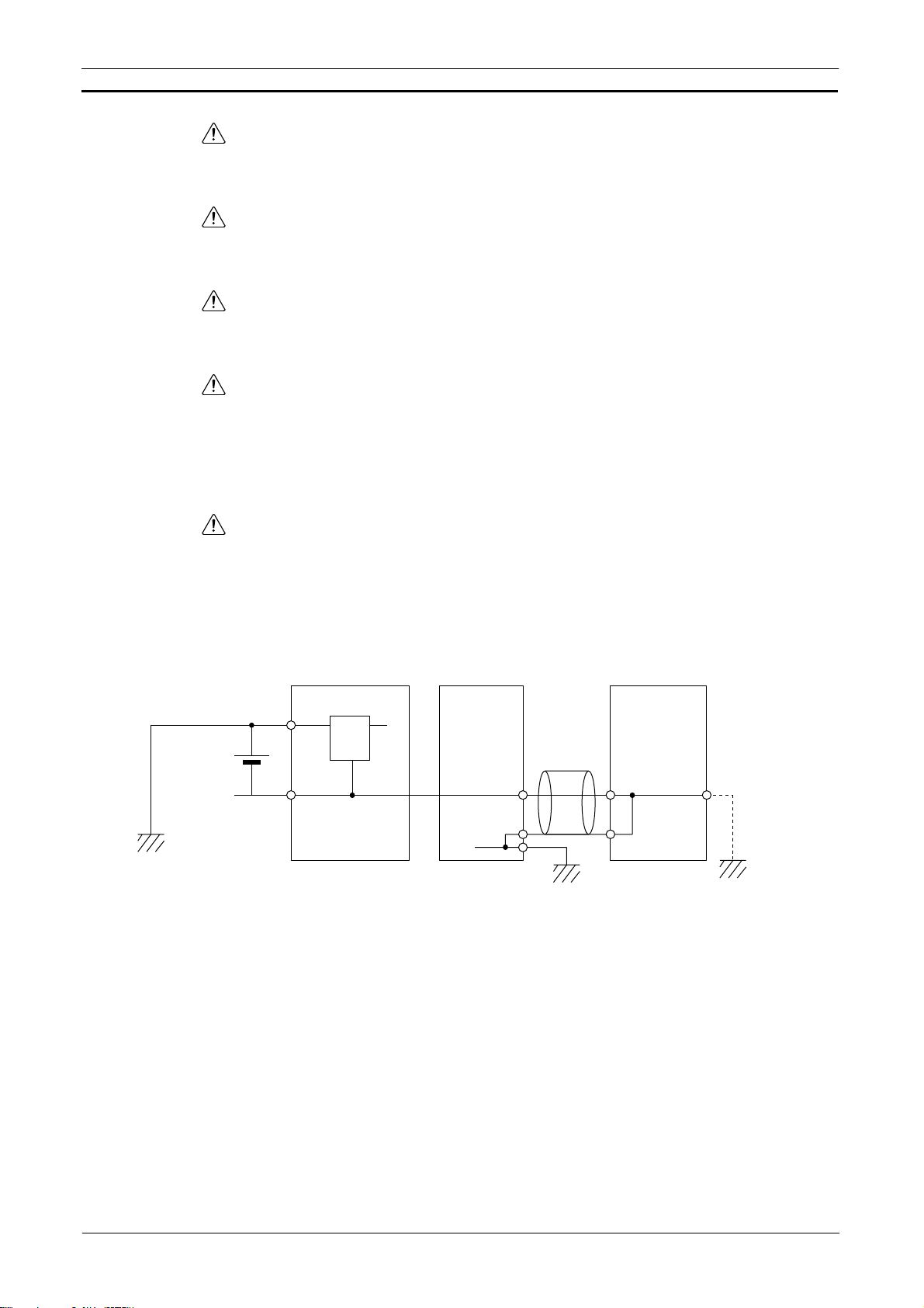
Caution
Caution is required when connecting peripheral devices, such as a
personal computer, to the PLC when Units with non-isolated power
supplies, such as the CS1W-CLK12/CLK52(-V1), that are connected to an
external power supply are mounted to the PLC. If the 24-V side is grounded
on the external power supply, a short will be created if the 0-V side of the
peripheral device is grounded. When connecting peripheral devices, either
ground the 0-V side of the external power supply or do not ground the
external power supply at all.
External power
supply
FG
24-VDC
0-VDC
Non-isolated
power supplies
Cable
0-VDC
FG
Controller Link unit Peripheral devices
CPU unit
FG
0-VDC
FG
CX-Programmer_Page (ix)
Page 13

OMRON CX-Programmer – Operation Manual
Application Precaution
Observe the following precautions when using the CX-Programmer.
• Observe the following precautions before starting the CX-Programmer.
• Exit all applications not directly related to the CX-Programmer.
Particularly exit any software such as screen savers, virus checkers,
email or other communications software, and schedulers or other
applications that start up periodically or automatically.
• Disable sharing hard disks, printers, or other devices with other
computers on any network.
• With some notebook computers, the RS-232C port is allocated to a
modem or an infrared port by default. Follow the instructions in
documentation for your computer and enable using the RS-232C port
as a normal serial port.
• With some notebook computers, the default settings for saving
energy do not supply the rated power to the RS-232C port. There
may be both Windows settings for saving energy, as well as setting
for specific computer utilities and BIOS. Following the instructions in
documentation for your computer, disable all energy saving settings.
• Do not turn OFF the power supply to the PLC or disconnect the
connecting cable while the CX-Programmer is online with the PLC. The
computer may malfunction.
• With the CS/CJ-series PLCs, when creating an AUTOEXEC.IOM file
from the CX-Programmer to automatically transfer data at startup, set the
first write address to D20000 and be sure that the size of data written
does not exceed the size of the DM Area. When the data file is read from
the Memory Card at startup, data will be written in the CPU Unit starting
at D20000 even if another address was set when the AUTOEXEC.IOM
file was created. Also, if the DM Area is exceeded (which is possible
when the CX-Programmer is used), the remaining data will be written to
the EM Area. Refer to information on file operations in the CS/CJ-series
Programming Manual for details.
• Confirm that no adverse effect will occur in the system before attempting
any of the following. Not doing so may result in an unexpected operation.
Changing the operating mode of the PLC.
• Force-setting/force-resetting any bit in memory.
• Changing the present value of any word or any set value in memory.
• Check the user program for proper execution before actually running it
on the Unit. Not checking the program may result in an unexpected
operation.
• Precaution on Using Indirect DM and EM Addresses in Comparison
Instructions:
When indirect DM or EM addresses are used as operands in comparison
instructions, the top portion of the comparison instruction will be displayed
in yellow when it is being monitored. At that time the power flow will not be
monitored to the right of such comparison instructions. The contact and
coil status, and present values of operands in special instructions will be
displayed normally.
CX-Programmer_Page (x)
Page 14

OMRON CX-Programmer – Operation Manual
• The user program and parameter area data in CS1-H CPU Units is
backed up in the built-in flash memory. The BKUP indicator will light on
the front of the CPU Unit when the backup operation is in progress. Do
not turn OFF the power supply to the CPU Unit when the BKUP indicator
is lit. The data will not be backed up if power is turned OFF.
To display the status of writing to flash memory on the CX-Programmer,
place a checkmark by Display dialog to show PLC Memory Backup
Status on the PLC properties and then select Windows | PLC Memory
Backup Status from the Windows menu.
• Precaution in Changing the PLC Type
On the CX-Programmer, you can change the PLC (device) type or CPU
type. When these are changed, however, only the data for the ladder
program and the symbol tables are changed. The following data will be
initialized and must be reset.
• PLC Setup
• Expansion instructions
• I/O tables
• PLC memory
Particularly the PLC Setup has a large impact on PLC system operation.
Be careful to reset all require settings after changing the PLC type.
If expansion instruction allocations are not reset, program errors could
occur, preventing the PLC from running. Always restore the expansion
instruction allocates to the previous settings after changing the PLC
type.
CX-Programmer_Page (xi)
Page 15

OMRON CX-Programmer – Operation Manual
Observe the following precautions when using the CX-Net.
• Do not change the operating mode of the CPU Unit without first
confirming that operation of the controlled system will not be affect.
• Do not run the user program on the PLC until its operation has been
checked sufficiently.
• The data link mode (manual setting or automatic setting) and data link
method are determined according to the data link setting in the startup
node. In the startup node, set a data link table in the case of manual
setting and data link automatic setting parameters in the case of
automatic setting. If the settings are incorrect, the data link will not start.
• Check the following items before starting data links. If incorrect data link
tables or parameters are set, injury may result due to unexpected
operation of the system. Even if the correct data link tables and
parameters have been set, do not start or stop data links before verifying
that there will be no adverse influence on the system.
(1) Manually Set Data Links
Check the data link tables in each node participating in the data link to
see that they are correct.
Be sure that data link tables are deleted from nodes that are not
participating in the data links.
(2) Automatically Set Data Links
Be sure that the correct DM parameters have been set in the data link
startup node.
• CPU Bus Units will be automatically restarted when routing tables are
transferred from a Programming Device to the CPU Unit. Resetting is
required to use the new tables. Confirm that restarting the CPU Bus
Units will not adversely affect system operation before transferring
routing tables.
• When Special I/O Unit or CPU Unit settings are performed in the I/O
Table Window and then transferred from the PLC Memory Window, the
following warning will be displayed if the allocated DM Area/CIO Area
addresses set for Special I/O Units or CPU Bus Units in the I/O Table
Window on the computer overlap with the PLC data table addresses.
Unless the CPU Bus Unit or Special I/O Unit settings have been
previously transferred to the CPU Unit and the allocated DM Area/CIO
Area data in the PLC data table for Special I/O Units or CPU Bus Units is
to be overwritten, always click the No Button, shift the address, and
repeat the transfer procedure.
• CPU Bus Unit and Special I/O Unit settings are not checked for logical
consistency. Be very careful of the logical consisting of the overall
settings when making any setting that affects other settings, e.g., settings
that enable or disable other settings. Transfer the Special I/O Unit or
CPU Bus Unit settings to the PLC and then start operation, being aware
that any logical inconsistencies may produce unexpected operation.
• For example, if one setting selects either user settings or default settings
and is set to use the default settings, it will not automatically change to
enable user settings even if the related user settings are made. To use
the user settings, they will have to be enabled manually and specifically
in the setting that selects either user settings or default settings.
CX-Programmer_Page (xii)
Page 16
Unit Versions of CS/CJ/CP-series CPU Units
Unit Versions
A “unit version” has been introduced to manage CPU Units in the CS/CJ/CP
Series according to differences in functionality accompanying Unit upgrades.
This applies to the CJ2, CS1-H, CJ1-H, CJ1M, CS1D, CP1H, CP1L, and
CP1E CPU Units.
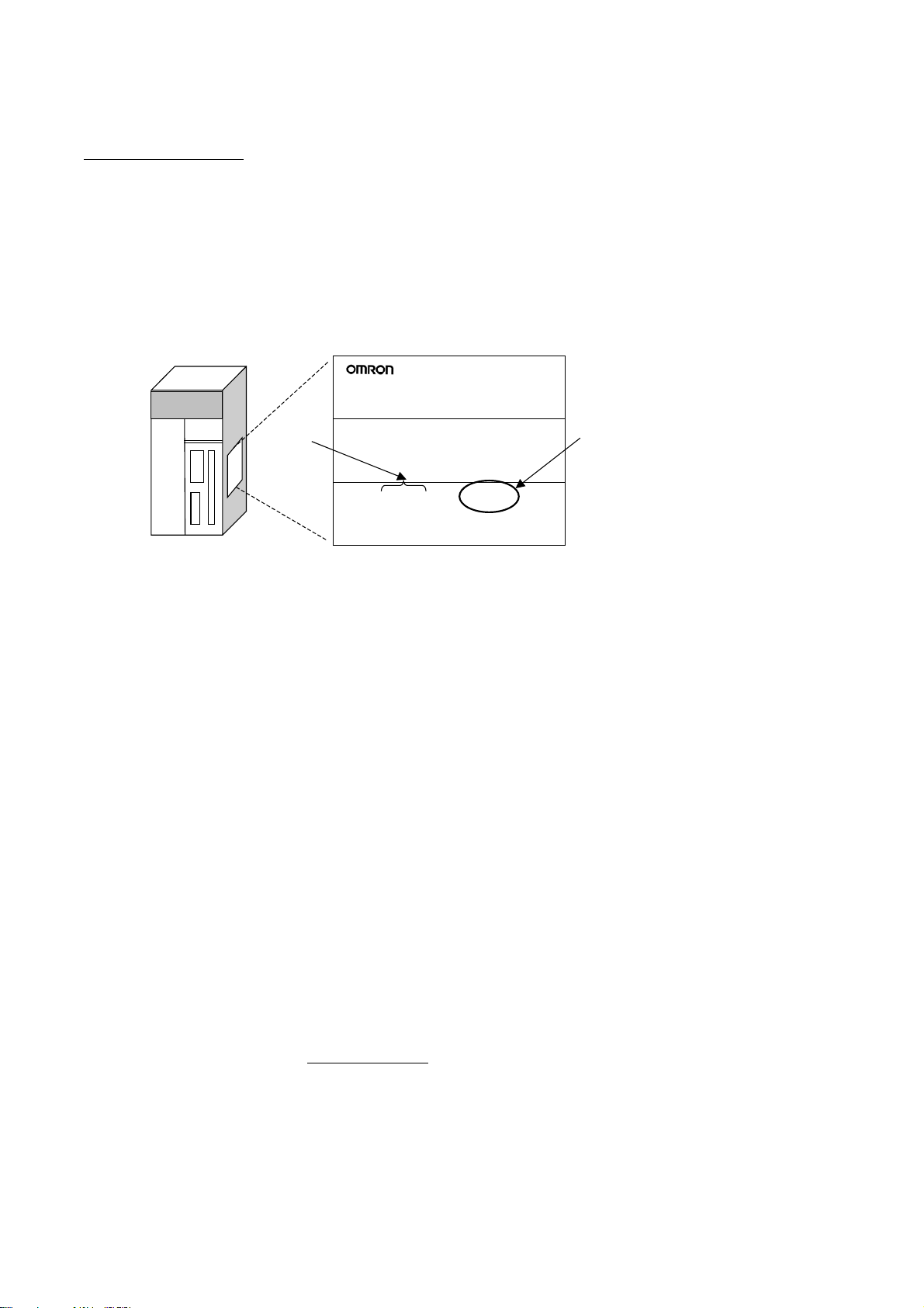
Notation of Unit Versions on Products
The unit version is given to the right of the lot number on the nameplate of
the products for which unit versions are being managed, as shown below.
Produce nameplateCS/CJ/CP-series CPU Unit
CS1H-CPU67H
CPU UNIT
Confirming Unit Versions
with Support Software
Lot No.
Lot No. 040715 0000 Ver.3.0
OMRON Corporation MADE IN JAPAN
Unit version
Example for unit version 3.0
• CS1-H, CJ1-H, and CJ1M CPU Units (except for low-end models)
manufactured on or before November 4, 2003 do not have a unit version
given on the CPU Unit (i.e., the location for the unit version shown above is
blank).
• The unit version of the CJ1-H-R CPU Units begins at version 4.0.
• The unit version of the CS1-H, CJ1-H, and CJ1M CPU Units, as well as the
CS1D CPU Units for Single-CPU Systems, begins at version 2.0.
• The unit version of the CS1D CPU Units for Duplex-CPU Systems begins
at version 1.1.
• The unit version of the CP1H/CP1L/CP1E CPU Units begins at version 1.0,
except for the CP1H-Y@@@@-@, for which the unit version begins at
version 1.1.
• CPU Units for which a unit version is not given are called Pre-Ver.
CPU Units, such as Pre-Ver. 2.0 CPU Units and Pre-Ver. 1.1 CPU Units.
CX-Programmer version 4.0 can be used to confirm the unit version using
one of the following two methods.
• Using the PLC Information
• Using the Unit Manufacturing Information (This method can be used for
Special I/O Units and CPU Bus Units as well.)
@.@
Note CX-Programmer version 3.3 or lower cannot be used to confirm unit versions.
PLC Information
• If you know the device type and CPU type, select them in the Change PLC
Dialog Box, go online, and select PLC - Edit - Information from the
menus.
• If you don’t know the device type and CPU type, but are connected directly
to the CPU Unit on a serial line, select PLC - Auto Online to go online, and
then select PLC - Edit - Information from the menus.
In either case, the following PLC Information Dialog Box will be displayed.
CX-Programmer_Page (xiii)
Page 17
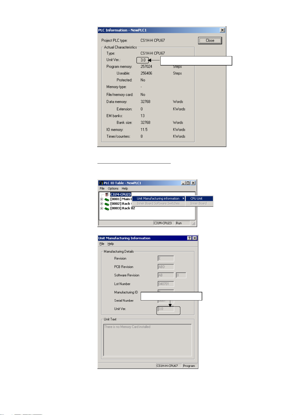
Unit version
Use the above display to confirm the unit version of the CPU Unit.
Unit Manufacturing Information
In the IO Table Window, right-click and select Unit Manufacturing
information - CPU Unit.
The following Unit Manufacturing information Dialog Box will be displayed
Unit version
Use the above display to confirm the unit version of the CPU Unit connected
online.
CX-Programmer_Page (xiv)
Page 18
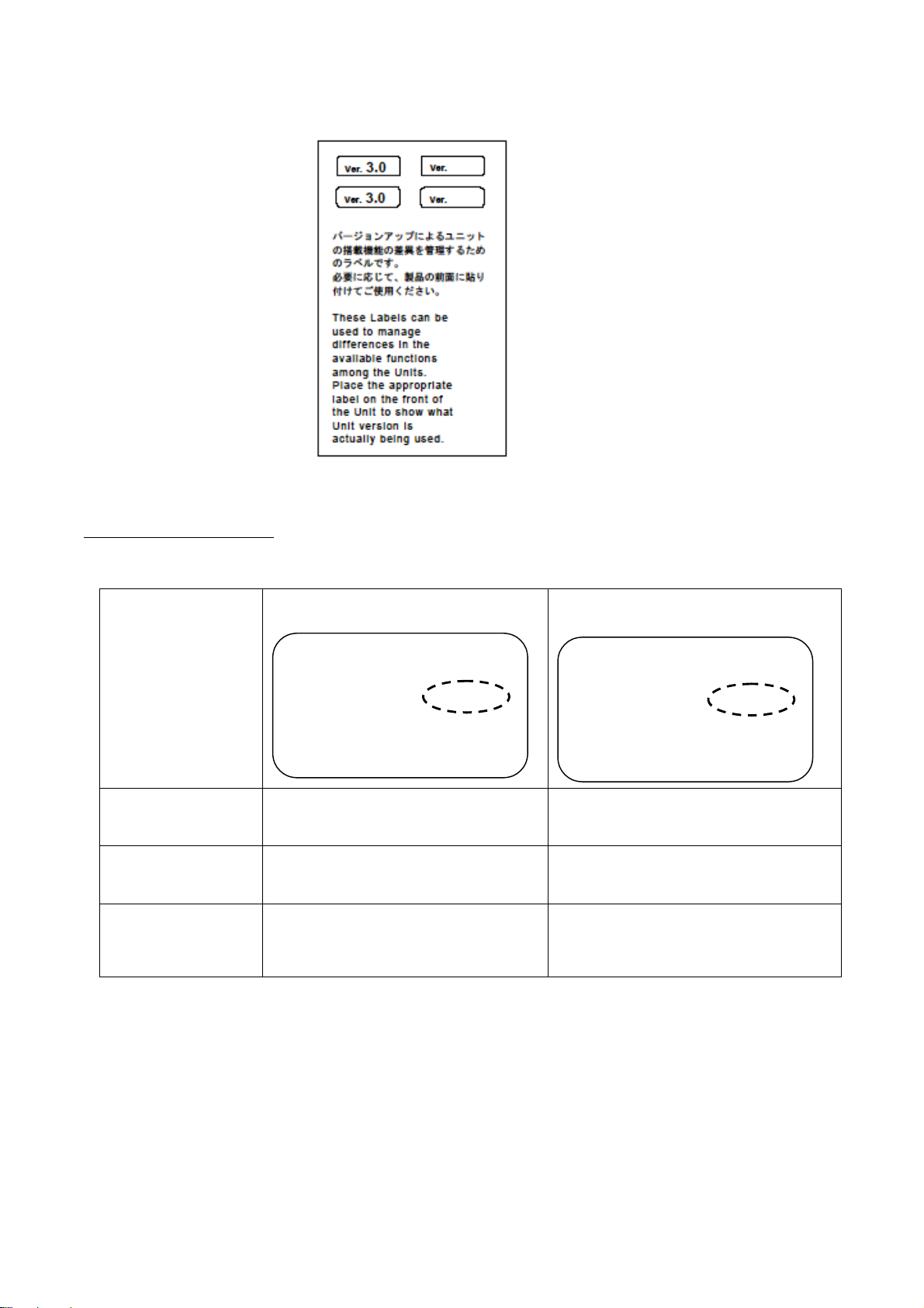
Using the Unit Version Labels
Unit Version Notation
The following unit version labels are provided with the CPU Unit.
These labels can be attached to the front of previous CPU Units to
differentiate between CPU Units of different unit versions.
Product nameplate
Meaning
Designating individual
CPU Units (e.g., the
CS1H-CPU67H)
Designating groups of
CPU Units (e.g., the
CS1-H CPU Units)
Designating an entire
series of CPU Units
(e.g., the CS-series
CPU Units)
In this manual, the unit version of a CPU Unit is given as shown in the
following table.
CPU Units on which no unit version is
given
Lot No. XXXXXX XXXX
OMRON Corporation MADE IN JAPAN
Units on which a version is given
@.@)
(Ver.
Lot No. XXXXXX XXXX
Ver.@.@
Pre-Ver. 2.0 CS1-H CPU Units CS1H-CPU67H CPU Unit Ver. @.@
Pre-Ver. 2.0 CS1-H CPU Units CS1-H CPU Units Ver. @.@
Pre-Ver. 2.0 CS-series CPU Units CS-series CPU Units Ver. @.@
CX-Programmer_Page (xv)
Page 19
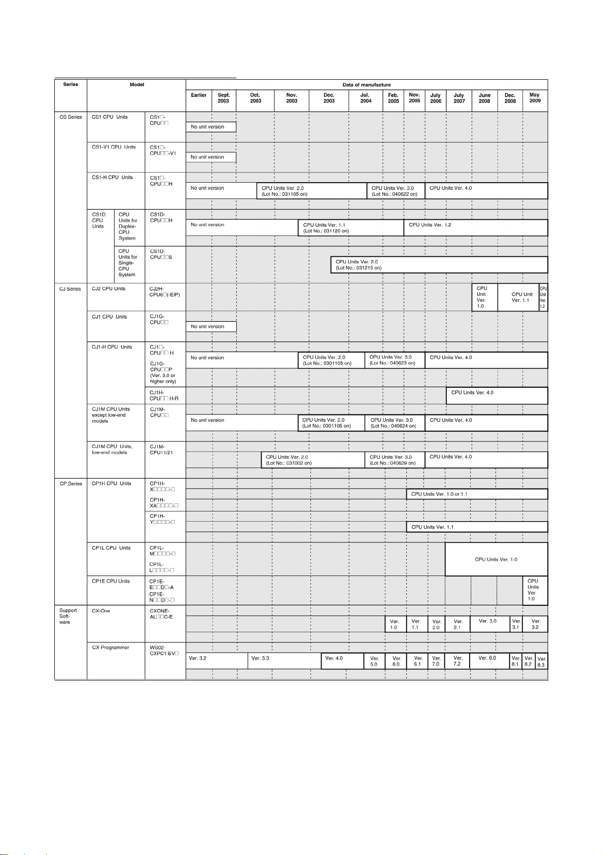
Unit Versions and Lot Numbers
CX-Programmer_Page (xvi)
Page 20

Function Support by Unit Version
CS1-H CPU Units (CS1@-CPU@@H)
Function
Downloading and Uploading Individual Tasks
Improved Read Protection Using Passwords
Write Protection from FINS Commands Sent to CPU Units via
Networks
Online Network Connections without I/O Tables
Communications through a Maximum of 8 Network Levels
Connecting Online to PLCs via NS-series PTs
Setting First Slot Words
Automatic Transfers at Power ON without a Parameter File
Automatic Detection of I/O Allocation Method for Automatic
Transfer at Power ON
Operation Start/End Times
New
Application
Instructions
MILH, MILR, MILC
=DT, <>DT, <DT, <=DT, >DT, >=DT
BCMP2
GRY
TPO
DSW, TKY, HKY, MTR, 7SEG
EXPLT, EGATR, ESATR, ECHRD, ECHWR
Reading/Writing CPU Bus Units with IORD/IOWR
PRV2
Unit version
Pre-Ver. 2.0 CPU
Units
--- OK
--- OK
--- OK
--- OK
--- OK
OK from lot number
030201
OK for up to 8 groups OK for up to 64 groups
--- OK
--- ---
--- OK
--- OK
--- OK
--- OK
OK from lot number
030201
--- OK
--- OK
--- OK
OK from lot number
030418
--- ---
CPU Units Ver. 2.0 or
later
OK
OK
OK
CX-Programmer_Page (xvii)
Page 21

CS1D CPU Units
Function
Functions
unique to
CS1D CPU
Units
Downloading and Uploading Individual Tasks
Improved Read Protection Using Passwords
Write Protection from FINS Commands Sent
to CPU Units via Networks
Online Network Connections without I/O
Tables
Communications through a Maximum of 8
Network Levels
Connecting Online to PLCs via NS-series
PTs
Setting First Slot Words
Automatic Transfers at Power ON without a
Parameter File
Automatic Detection of I/O Allocation Method
for Automatic Transfer at Power ON
Operation Start/End Times
New
Application
Instructions
Duplex CPU Units OK OK ---
Online Unit Replacement OK OK OK
Duplex Power Supply Units OK OK OK
Duplex Controller Link Units OK OK OK
Duplex Ethernet Units --- OK OK
MILH, MILR, MILC
=DT, <>DT, <DT, <=DT, >DT,
>=DT
BCMP2
GRY
TPO
DSW, TKY, HKY, MTR, 7SEG
EXPLT, EGATR, ESATR,
ECHRD, ECHWR
Reading/Writing CPU Bus
Units with IORD/IOWR
PRV2
CS1D CPU Units for Duplex-CPU
Systems (CS1D-CPU@@H)
Pre-Ver. 1.1 CPU
Units
--- --- OK
--- --- OK
--- --- OK
--- --- OK
--- --- OK
--- --- OK
--- --- OK for up to 64
--- --- OK
--- --- ---
--- OK OK
--- --- OK
--- --- OK
--- --- OK
--- --- OK
--- --- OK
--- --- OK
--- --- OK
--- --- OK
--- --- ---
CPU Unit Ver. 1.1 CPU Unit Ver. 2.0
CS1D CPU Units
for Single-CPU
Systems
(CS1D-CPU@@S)
or later
groups
CX-Programmer_Page (xviii)
Page 22

CJ1-H/CJ1M CPU Units
Function
Downloading and Uploading
Individual Tasks
Improved Read Protection
Using Passwords
Write Protection from FINS
Commands Sent to CPU Units
via Networks
Online Network Connections
without I/O Tables
Communications through a
Maximum of 8 Network Levels
Connecting Online to PLCs via
NS-series PTs
Setting First Slot Words
Automatic Transfers at Power
ON without a Parameter File
Automatic Detection of I/O
Allocation Method for
Automatic Transfer at Power
ON
Operation Start/End Times
New
Application
Instructions
MILH, MILR,
MILC
=DT, <>DT, <DT,
<=DT, >DT,
>=DT
BCMP2
GRY
TPO
DSW, TKY, HKY,
MTR, 7SEG
EXPLT, EGATR,
ESATR, ECHRD,
ECHWR
Reading/Writing
CPU Bus Units
with IORD/IOWR
PRV2
CJ1-H CPU Units CJ1M CPU Units
(CJ1H-CPU@@H-R)
(CJ1@-CPU@@H)
(CJ1G-CPU@@P)
Pre-Ver. 2.0
CPU Units
--- OK --- OK OK
--- OK --- OK OK
--- OK --- OK OK
OK, but only if
I/O table
allocation at
power ON is set
OK for up to 8
groups
OK from lot
number 030201
--- OK --- OK OK
--- OK --- OK OK
--- OK --- OK OK
--- OK --- OK OK
--- OK --- OK OK
--- OK --- OK OK
--- OK OK OK OK
OK from lot
number 030201
--- OK --- OK OK
--- OK --- OK OK
--- OK --- OK OK
--- OK --- OK OK
--- --- --- OK, but only for
CPU Units
Ver. 2.0
OK OK, but only if
OK for up to 64
groups
OK OK from lot
OK OK from lot
CJ1M-CPU12/13/22/23 CJ1M-
Pre-Ver. 2.0
CPU Units
I/O table
allocation at
power ON is set
OK for up to 8
groups
number 030201
number 030201
CPU Units
Ver. 2.0
OK OK
OK for up to 64
groups
OK OK
OK OK
models with
built-in I/O
CPU11/21
CPU Units
Ver. 2.0 or
later
OK for up to 64
groups
OK, but only for
models with
built-in I/O
CX-Programmer_Page (xix)
Page 23

Functions Supported by Unit Version 3.0 or Later
CS1-H CPU Units (CS1@-CPU@@H)
Unit version Function
Pre-Ver. 2.0, Ver.
2.0
Function blocks (supported for CX-Programmer Ver.
5.0 or higher)
Serial Gateway (converting FINS commands to
CompoWay/F commands at the built-in serial port)
Comment memory (in internal flash memory) --- OK OK
Expanded simple backup data --- OK OK
New
application
instructions
Additional
instruction
functions
New
application
instructions
Improved
function block
(FB) functions
Using ST language programming in tasks --- --- OK with CX-
Using SFC programming in tasks --- --- OK with CX-
TXDU(256), RXDU(255) (support
no-protocol communications with
Serial Communications Units with
unit version 1.2 or later)
Model conversion instructions:
XFERC(565), DISTC(566),
COLLC(567), MOVBC(568),
BCNTC(621)
Special function block instructions:
GETID(286)
TXD(235) and RXD(236)
instructions (support no-protocol
communications with Serial
Communications Boards with unit
version 1.2 or later)
ASCII conversion instructions
(NUMBER-TO-ASCII and ASCIITO- NUMBER)
Text File Write (TWRIT)
Online editing of function blocks --- --- OK
Input-output variables are
supported.
(Input-output variables can be
specified in arrays.)
The STRING data type and textstring processing functions are
supported in ST language.
--- OK OK
--- OK OK
--- OK OK
--- OK OK
--- OK OK
--- OK OK
--- --- OK
--- --- OK
--- --- OK
Note: CX-Programmer version 7.0 or higher is required to use functions added for unit version
4.0. Additional functions are supported if CX-Programmer version 7.2 or higher is used.
Ver. 3.0 Ver. 4.0
(See note.)
Programmer Ver. 7.2
or higher
Programmer Ver. 7.2
or higher
CS1D CPU Units
Unit version 3.0 (Ver. 3.0) is not supported.
CX-Programmer_Page (xx)
Page 24

CJ1-H/CJ1M CPU Units (CJ1@-CPU@@H, CJ1M-CPU@@)
Unit version Function
Pre-Ver. 2.0,
Ver. 2.0
Function blocks (supported for CX-Programmer Ver.
5.0 or higher)
Serial Gateway (converting FINS commands to
CompoWay/F commands at the built-in serial port)
Comment memory (in internal flash memory) --- OK OK
Expanded simple backup data --- OK OK
Additional
instruction
functions
New
application
instructions
Additional
instruction
functions
New
application
instructions
Improved
function block
(FB) functions
Using ST language programming in tasks --- --- OK with CX-
Using SFC programming in tasks --- --- OK with CX-
PRV(881) and PRV2(883)
instructions: Added high-frequency
calculation methods for calculating
pulse frequency. (CJ1M CPU Units
only)
TXDU(256), RXDU(255) (support
no-protocol communications with
Serial Communications Units with
unit version 1.2 or later)
Model conversion instructions:
XFERC(565), DISTC(566),
COLLC(567), MOVBC(568),
BCNTC(621)
Special function block instructions:
GETID(286)
TXD(235) and RXD(236)
instructions (support no-protocol
communications with Serial
Communications Boards with unit
version 1.2 or later)
ASCII conversion instructions
(NUMBER-To-ASCII and ASCIITO NUMBER)
Online editing of function blocks --- --- OK
Input-output variables are
supported. (Input-output variables
can be specified in arrays.)
The STRING data type and textstring processing functions are
supported in ST language.
--- OK OK
--- OK OK
--- OK OK
--- OK OK
--- OK OK
--- OK OK
--- OK OK
--- --- OK
--- --- OK
--- --- OK
Ver. 3.0 Ver. 4.0
(See note.)
Programmer Ver. 7.2
or higher
Programmer Ver. 7.2
or higher
Note: CX-Programmer version 7.0 or higher is required to use functions added for unit version
4.0. Additional functions are supported if CX-Programmer version 7.2 or higher is used.
CX-Programmer_Page (xxi)
Page 25

Functions Supported by Unit Version for CJ2 CPU Units (CJ2H-CPU6@-EIP, CJ2HCPU6@)
Unit Version 1.2 or Later
Unit Version 1.1 or Later
CX-Programmer version 8.3
functions added for unit version 1.2.
Unit CJ2H CPU Unit
Model
Item
EM Area force-setting/resetting Supported.
CX-Programmer version 8.1
functions added for unit version 1.1.
Unit CJ2H CPU Unit
Model
Item
High-speed interrupt function
Decreased overhead time for interrupt tasks
Minimum interval setting of 0.1 ms for Scheduled
Interrupt Task
Changing the minimum cycle time setting in
MONITOR mode
Synchronous unit operation Supported. Not supported.
or higher must be used to enable using the
CJ2H-CPU6@-EIP
CJ2H-CPU6@
Unit version
or higher must be used to enable using the
Unit version
Unit version 1.1 Unit version 1.0
Supported. Not supported.
Supported. Not supported.
Unit version 1.2
CJ2H-CPU6@-EIP
CJ2H-CPU6@
Unit Version 1.0
All functions that are supported by unit version 4.0 or later of the CJ1 CPU
Units are supported by unit version 1.0 of the CJ2 CPU Units.
CX-Programmer version 8.0 or higher must be used to enable using unit
version 1.0 of the CJ2 CPU Units.
CX-Programmer_Page (xxii)
Page 26

Functions Supported by Unit Version for CP-series CPU Units
Functions Supported by Unit Version 1.0 and 1.1
Functionality is the same as that for CS/CJ-series CPU Units with unit version
3.0. The functionality added for CS/CJ-series CPU Unit unit version 4.0 is not
supported.
CP1H CPU Units
• CX-Programmer version 6.11 or higher is required to use CP1H-X@@@@-
@/XA@@@@-@ with unit version 1.1 or 1.0.
• CX-Programmer version 6.20 or higher is required to use CP1H-Y@@@@-
@ with unit version 1.1.
CPU Unit CP1H CPU Unit
Model CP1H-@@@@-@
CP1H-XA@@@@-@
(See note 1.)
Function
Pulse
outputs
Unit version
Allocated built-in
I/O terminals
Special pulse
output terminals
Ver. 1.1 or
later
4 axes at
100 kHz
None 2 axes at 1 kHz
Ver. 1.0 Ver. 1.1
2 axes at
100 kHz
2 axes at
30 kHz
Note 1. The unit version for the CP1H-X@@@@-@/XA@@@@-@ begins at 1.0.
2. The unit version for the CP1H-X@@@@-@ begins at 1.1.
CP1H-Y@@@@-@
(See note 2.)
2 axes 100 kHz
3. CX-Programmer version 7.11 or higher is required to use CP1L CPU Units with unit
version 1.0.
CX-Programmer_Page (xxiii)
Page 27
Unit Versions and Programming Devices
CX-Programmer version 4.0 or higher must be used to enable using the
functions added for CPU Unit Ver. 2.0. The following tables show the
relationship between unit versions and CX-Programmer versions.
Unit Versions and Programming Devices for CJ2 CPU Units
CPU Unit Functions
Ver. 7.1 or lower Ver. 8.0 Ver. 8.1 Ver. 8.2 Ver. 8.3
CJ2H-CPU6@-EIP
Unit version 1.0
CJ2H-CPU6@-EIP
Unit version 1.1
CJ2H-CPU6@
Unit version 1.1
CJ2H-CPU6@-EIP
Unit version 1.2
CJ2H-CPU6@
Unit version 1.2
Functions for unit version
1.0
Functions added for unit
version 1.1
Functions added for unit
version 1.1
Functions added for unit
version 1.2
Functions added for unit
version 1.2
×
×
×
×
×
×: Cannot be used, ∆: Can be used except for new functions added for unit versions, ❍: Can be used
Note 1. It is not necessary to upgrade the version of the CX-Programmer if functionality that was
enhanced for the upgrade of the CPU Unit will not be used.
2. CX-Programmer version 8.1 or higher is required to use the functions added for unit
version 1.1. The high-speed interrupt function and changing the minimum cycle time
setting in MONITOR mode, however, are also supported by CX-Programmer version
8.02.
Required Programming Device
CX-Programmer
❍ ❍ ❍ ❍
∆
∆
∆ ∆ ∆
∆ ∆ ∆
❍ ❍ ❍
❍ ❍ ❍
❍
❍
3. A Programming Console cannot be used with a CJ2H CPU Unit.
Unit Versions and Programming Devices for CPU Units Other Than CJ2 CPU Units
CPU Unit Functions
CS/CJ Series CPU
Units, Unit Ver. 4.0
CS/CJ Series CPU
Units, Unit Ver. 3.0
CS/CJ Series CPU
Units, Unit Ver. 2.0
CS1D CPU Units for
Single-CPU Systems,
Unit Ver. 2.0
CS1D CPU Units for
Duplex-CPU Systems,
Unit Ver.1.1
Functions added for unit
version 4.0
Functions added for unit
version 3.0
Functions added for unit
version 2.0
Functions added for unit
version 2.0
Functions added for unit
version 1.1
Ver. 3.3 Ver. 4.0 Ver. 5.0
∆ ∆ ∆
∆ ∆
∆
❍ ❍ ❍ ❍ ❍
∆
❍ ❍ ❍ ❍ ❍
∆
❍ ❍ ❍ ❍ ❍
Required Programming Device
CX-Programmer
Ver. 7.0 Ver. 7.2 Ver. 8.0
Ver. 6.0
❍ ❍ ❍
❍ ❍ ❍ ❍
×: Cannot be used, ∆: Can be used except for new functions added for unit versions, ❍: Can be used
Note 1. As shown above, there is no need to upgrade to CX-Programmer version 4.0 as long as
the functions added for unit version 2.0 or unit version 1.1 are not used.
2. CX-Programmer version 7.0 or higher is required to use functions added for unit version
4.0. Additional functions are supported if CX-Programmer version 7.2 or higher is used.
or later
(See note
4.)
3. Unit version 4.2 of the CJ1H-CPU6@-R is supported only by CX-Programmer version 8.0
or higher.
4. CX-Programmer version 8.0 or higher is required to use unit version 4.2 of the CJ1H-
CPU6@-R.
CX-Programmer_Page (xxiv)
Page 28
Unit Versions of CP-series CPU Units and Programming Devices
CX-Programmer version CPU Unit Model Unit
or later
CP1H CPU Units
CP1L CPU Units
CP1E CPU Units
CP1H-X@@@@-@
CP1H-XA@@@@-@
CP1H-Y@@@@-@
CP1L-M@@@@-@
CP1L-L@@@@-@
CP1E-E@@D@-A
CP1E-N@@D@-@
version
Ver. 1.1 OK OK OK OK
Ver. 1.0 OK OK OK OK
Ver. 1.1 --- OK OK OK
Ver. 1.0 --- --- OK OK
Ver. 1.0 --- --- --- OK
Ver. 6.11 Ver. 6.20 Ver. 7.11 Ver. 8.2
Note 1. Functionality of CP1H CPU Units with unit version 1.0 or 1.0 and CP1L CPU Units with
unit version 1.0 is the same as that for CS/CJ-series CPU Units with unit version 3.0.
The functionality added for CS/CJ-series CPU Unit unit version 4.0 is not supported.
2. There is no need to upgrade to CX-Programmer as long as the upgraded functionality is
not used.
Device Type Setting
The unit version does not affect the setting made for the device type on the
CX-Programmer. Select the device type as shown in the following table
regardless of the unit version of the CPU Unit.
Series CPU Unit group CPU Unit model Device type setting on
CX-Programmer
CS Series
CJ Series
CS1D CPU Units for Duplex-CPU Systems
CS1D CPU Units for Single-CPU Systems
CJ2 CPU Units
CJ1-H CPU Units
CS1G-CPU@@H
CS1H-CPU@@H
CS1D-CPU@@H
CS1D-CPU@@S
CJ2H-CPU6@(-EIP)
CJ1G-CPU@@H
CS1G-H CS1-H CPU Units
CS1H-H
CS1D-H (or CS1H-H)
CS1D-S
CJ2H
CJ1G-H
CJ1G- CPU@@P
CJ1H-CPU@@H–R
CJ1H-CPU@@H
CP Series
CJ1M CPU Units
CP1H CPU Units
CJ1M-CPU@@
CP1H-X@@@@-@
CJ1M
CP1H
CP1H-XA@@@@-@
CP1H-Y@@@@-@
CP1L CPU Units
CP1L-M@@@@-@
CP1L
CP1L-L@@@@-@
CP1E CPU Units
CP1E-E@@D@-A
CP1E
CP1E-N@@D@-@
Note Device types not supported by the CX-Programmer version that is being used will not be
displayed on the pull-down list of the Device type Field.
CX-Programmer_Page (xxv)
Page 29
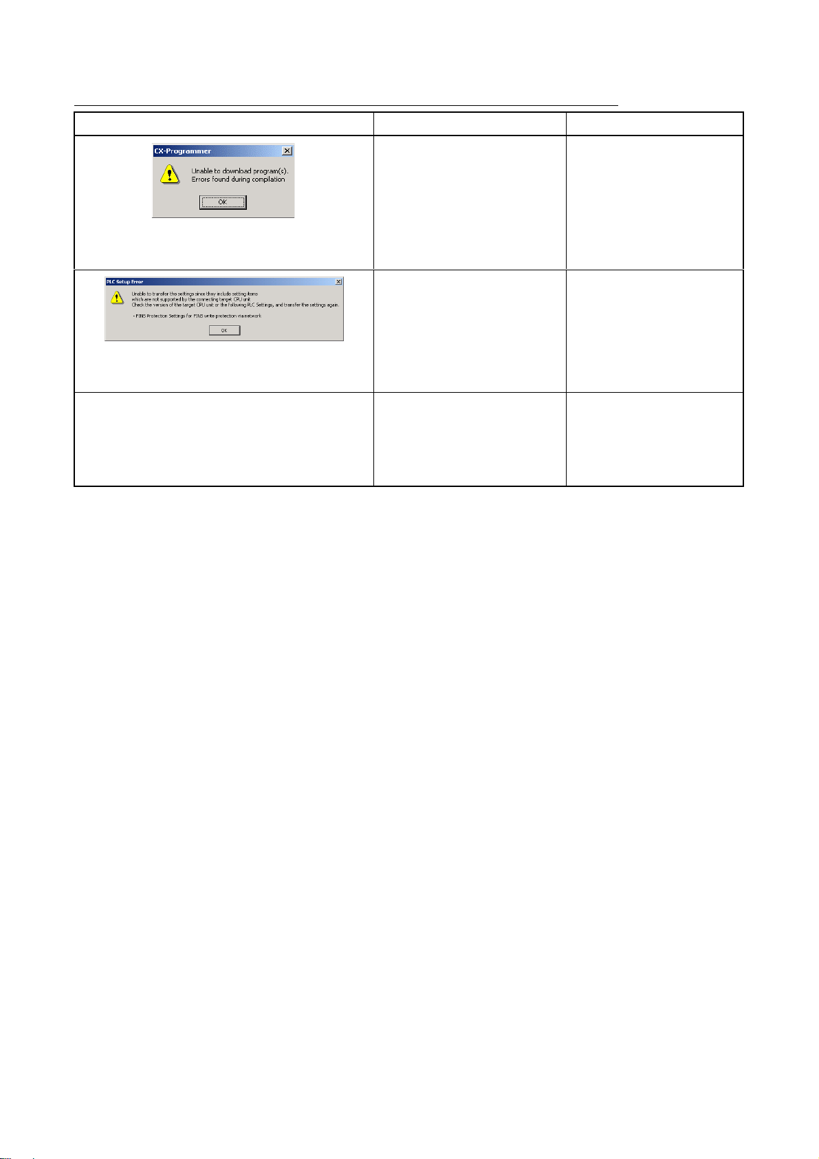
Troubleshooting Problems with Unit Versions on the CX-Programmer
Problem Cause Solution
After the above message is displayed, a compiling
error will be displayed on the Compile Tab Page in
the Output Window.
"????" is displayed in a program transferred from the
PLC to the CX-Programmer.
An attempt was made using CXProgrammer version 4.0 or
higher to download a program
containing instructions supported
only by CPU Units Ver. 2.0 or
later to a Pre-Ver. 2.0 CPU Units.
An attempt was made using CXProgrammer version 4.0 or
higher to download a PLC Setup
containing settings supported
only by CPU Units Ver. 2.0 or
later (i.e., not set to their default
values) to a Pre-Ver. 2.0 CPU
Units.
CX-Programmer version 3.3 or
lower was used to upload a
program containing instructions
supported only by CPU Units
Ver. 2.0 or later from a CPU Unit
Ver. 2.0 or later.
Check the program or change
the CPU Unit being
downloaded to a CPU Unit
Ver. 2.0 or later.
Check the settings in the PLC
Setup or change the CPU Unit
being downloaded to a CPU
Unit Ver. 2.0 or later.
The new instructions cannot
be uploaded using CXProgrammer version 3.3 or
lower. Use CX-Programmer
version 4.0 or higher.
CX-Programmer_Page (xxvi)
Page 30

Page 31

PART 1:
CX-Programmer
Page 32

Page 33

OMRON PART 1: CX-Programmer
Notice
OMRON products are manufactured for use according to proper procedures by a qualified operator and
only for the purposes described in this manual.
The following conventions are used to indicate and classify precautions in this manual. Always heed the
information provided in them. Failure to heed precautions can result in injury to people or damage to the
product.
DANGER Indicates an imminently hazardous situation which, if not avoided, will result in
death or serious injury. Additionally, there may be severe property damage.
WARNING Indicates a potentially hazardous situation which, if not avoided, could result in
death or serious injury. Additionally, there may be severe property damage.
Caution Indicates a potentially hazardous situation which, if not avoided, may result in
minor or moderate injury, or property damage.
OMRON Product References
All OMRON products are capitalized in this manual. The word “Unit” is also capitalized when it refers to
an OMRON product, regardless of whether or not it appears in the proper name of the product.
The abbreviation “PLC” means Programmable Logic Controller and is not used as an abbreviation for
anything else.
CX-Programmer_Page (i)
Page 34

OMRON PART 1: CX-Programmer
Visual Aids
The following headings appear in the left column of the manual to help you locate different types of
information.
Indicates information of particular interest for efficient and convenient operation of the product.
1, 2, 3…
OMRON, 2005
All rights reserved. No part of this publication may be reproduced, stored in a retrieval system, or
transmitted, in any form, or by any means, mechanical, electronic, photocopying, recording, or otherwise,
without the prior written permission of OMRON.
All copyright and trademarks acknowledged.
No patent liability is assumed with respect to the use of the information contained herein. Moreover,
because OMRON is constantly striving to improve its high-quality products, the information contained in
this manual is subject to change without notice. Every precaution has been taken in the preparation of this
manual. Nevertheless, OMRON assumes no responsibility for errors or omissions. Neither is any liability
assumed for damages resulting from the use of the information contained in this publication.
Indicates lists of one sort or another, such as procedures, checklists etc.
Represents a shortcut on the Toolbar to one of the options available on the menu of the same
window.
CX-Programmer_Page (ii)
Page 35

OMRON PART 1: CX-Programmer
About this Part
This part describes the CX-Programmer application and its ability to create and maintain programs for use
with OMRON SYSMAC CS/CJ/CP, CV and C PLCs. It does not provide detailed information concerning
the PLCs themselves, for this information the commercial manual for the device must be consulted.
This part contains the following chapters:
• Precautions. This portion describes general precautions for using the CX-Programmer (including
CX-Server PLC Tools).
• Version Upgrade Information. This portion describes the changes that have been made from version
3.0 to version 3.1 of the CX-Programmer.
• Chapter 1 Technical Specifications. This chapter describes the CX-Programmer software in general
terms and also provides details of the operating environment and minimum configuration necessary
for the satisfactory operation of CX-Programmer.
• Chapter 2 Quick Start Guide. This chapter describes the basic features of CX-Programmer together
with a simple tutorial for familiarization purposes.
• Chapter 3 Project Reference. This describes the features common to two or more parts of CX-
Programmer.
• Chapter 4 Reference. This chapter introduces the features contained in the Project workspace and
discusses their associated commands and features.
• Chapter 5 Advanced Topics. This chapter discusses the more advanced topics in relation to CX-
Programmer.
• Appendix A Toolbars and Keyboard Shortcuts. This appendix summarizes the toolbar and keyboard
shortcuts available from CX-Programmer.
A Glossary of Terms and Index are also provided.
CX-Programmer_Page (iii)
Page 36

OMRON PART 1: CX-Programmer
Functions Supported by the CXProgrammer Installed from the CX-One
• Starting Specialized Support Tools from the I/O Table Window
Previous version New version (CX-Programmer Installed from CX-One)
Each CPU Bus Unit or
Special I/O Unit’s
Programming Tool was
started individually.
Functionality Improved from Version 8.3 to 9.0
Compatible PLC Models
The CX-Programmer also supports CP1E-NA20 CPU Units (20-point CPU Units).
Supported Operating Systems
The CX-Programmer will run on Windows 7.
Data Structures Supported as Symbol Data Types
Data structures are not supported. CJ2 CPU Units now support data structures as
If the PLC model is set to the CS/CJ/CP-series, each Unit’s Programming Tool (e.g.,
CX-Integrator, CX-Protocol, CX-Position, or CX-Process Tool) can be started directly
from the Special I/O Unit or CPU Bus Unit in the I/O Table Window. When the
Specialized Support Tool is started, the CX-Programmer can pass information such as
the PLC model, Unit model, and online/offline status.
Previous version (version 8.3) New version (version 9.0)
symbol data types.
Enhanced Program Input Functions
Previous version (version 8.3) New version (version 9.0)
The input mode cannot be changed. A Smart Input Mode is supported that
automatically displays suggested instructions
and addresses.
The input mode can be changed from a menu or
a tool bar.
When copying circuits to create similar rungs
with different addresses, the addresses must be
input again.
The Address Incremental Copy function can be
used to easily create copies of similar circuit
structures with offset addresses.
Enhanced User Interface for Menu and Option Settings
Previous version (version 8.3) New version (version 9.0)
The display configuration for menus and options
cannot be changed.
Switching to Smart Style Mode is now possible
for the menu and option setting style.
Smart Style is the same type of menu and option
setting function as the one supported in CXProgrammer for CP1E.
Either the previous Classic Mode or the new
Smart Style Mode can be selected for the menus
and options by selecting Tools - Options and
then setting the Menu/Options Style on the
General Tab Page.
Changes to Search/Replace Dialog Boxes
Previous version (version 8.3) New version (version 9.0)
Searches can be performed only in the entire
PLC or in the data in the current view.
The setting for the item to be searched for was
very detailed and included bit addresses,
address, values (constants/numbers),
mnemonics, symbols, and I/O comments.
"Programs" has been added to the search range.
Searched objects have been grouped into
addresses, symbol names, and all (text strings).
CX-Programmer_Page (iv)
Page 37

OMRON PART 1: CX-Programmer
Previous version (version 8.3) New version (version 9.0)
Replacements can be performed only in the
entire PLC or in the data in the current view.
The setting for the item to be replaced was very
detailed and included bit addresses, address,
values (constants/numbers), mnemonics,
symbols, and I/O comments.
"Programs" has been added to the replacement
range.
Also, the selected circuits can be set as the
replacement range.
Searched objects have been grouped into
addresses, symbol names, mnemonics, and
comments.
Version 8.3 Upgrade Information
Functionality Improved from Version 8.2 to 8.3
Compatible PLC Models
The functionality improvements are supported for CJ2H CPU Units with unit version
1.2 or later.
TIMER and COUNTER Added as Symbol Data Types
Previous version (version 8.2) New version (version 8.3)
When defining timer numbers and counter
numbers as symbols, the following three different
symbols had to be registered in the symbols
table.
1. Timer numbers and counter numbers
specified in instruction operands had to
be defined as NUMBER symbols.
2. Timer and Counter Completion Flags
had to be defined as BOOL symbols.
3. Timer and counter present values had
to be defined as CHANNEL symbols.
Automatically assigning timer and counter
numbers in ladder programs was not possible.
TIMER and COUNTER symbols are supported
so that all of the previous three types of symbols
can be managed as one data type. (TIMER and
COUNTER are supported only by CJ2H CPU
Units with unit version 1.0 or later.)
TIMER: Can be used for 1) the timer number, 2)
the Timer Completion Flag, and 3) the timer
present value.
COUNTER: Can be used for 1) the counter
number, 2) the Counter Completion Flag, and 3)
the counter present value.
Automatic address assignment and layout are
supported for TIMER and COUNTER symbols.
(TIMER and COUNTER are supported only by
CJ2H CPU Units with unit version 1.0 or later.)
Force-setting/resetting Bits in EM Area
Previous version (version 8.2) New version (version 8.3)
Bits in the EM Area could be force-set/reset in
CJ2H CPU Units only for specific EM Area banks
for which automatic address assignment was
used.
With CJ2H CPU Units with unit version 1.2 or
later, PLC • Memory Allocate • EM Memory
Settings can be used to specify the EM Area
banks for which bits can be force-set/reset. (The
first bank is specified and force-setting/resetting
bits is possible in that bank and all banks
following it.) This is called the EM Area forcesetting/resetting function.
Searching for Symbol Names and Displaying Usage Locations from Cross-reference Pop-
ups
Previous version (version 8.2) New version (version 8.3)
Searching from cross-reference pop-ups was
possible only for address specifications. (To
search for symbols, you had to click the Browse
button and search for symbol names from the
Symbol Search Dialog Box.)
Symbol names can be specified directly in crossreference pop-ups to display a list of locations
that use the address of that symbol.
CX-Programmer_Page (v)
Page 38

OMRON PART 1: CX-Programmer
Version 8.2 Upgrade Information
Functionality Improved from Version 8.1 to 8.2
Connecting Online to the PLC through an NV-series PT*
Previous version (version 8.1) New version (version 8.2)
It was not possible to connect online from the
CX-Programmer through an NV-series PT to a
PLC connected to the NV-series PT.
*Functionality improved in version 8.21 over version 8.20.
CP1E CPU Unit Supported for Connecting Online to a PLC via an NS-series PT
Previous version (version 8.1) New version (version 8.2)
With a CP1E CPU Unit, it was not possible to
connect online from the CX-Programmer through
an NS-series PT to a PLC connected to the NSseries PT.
Compatible PLC Models
The functionality improvements are supported for CP-series CP1E CPU Units
with unit version 1.0.
It is now possible to connect online from the CXProgrammer through an NV-series PT to a PLC
connected to the NV-series PT.
With a CP1E-N@@D@-@ CPU Unit, it is now
possible to connect online from the CXProgrammer through an NS-series PT to a PLC
connected to the NS-series PT.
Online Connection to the PLC via an NS-series PT
Previous version (version 8.1) New version (version 8.2)
An online connection from the CX-Programmer
through an NS-series PT to a PLC connected to
the PT was not possible.
An online connection from the CX-Programmer
through an NS-series PT to a PLC connected to
the PT is possible when the PLC is connected to
the PT using a serial connection, Ethernet
connection, or Controller Link connection.
CX-Programmer_Page (vi)
Page 39

OMRON PART 1: CX-Programmer
Version 8.1 Upgrade Information
Functionality Improved from Version 8.0 to 8.1
Compatible PLC Models
The functionality improvements are supported for CJ-series CJ2 CPU Units
(CJ2H-CPU6@(-EIP)) with unit version 1.1.
Support for Synchronous Unit Operation
Support has been added for the synchronous unit operation function for a
combination of a CJ-series CJ2 CPU Unit (CJ2H-CPU6@ (-EIP)) with unit version
1.1 and CJ-series Position Control Units (CJ1W-NC@@4). Settings and
monitoring are now possible for synchronous unit operation.
Improved Special I/O Unit and CPU Bus Unit Setup Functionality
Multiple dialog boxes can now be opened simultaneously when setting CJ-series
Position Control Unit (CJ1W-NC@@4) parameters. In addition, the CAM Data
Creation Software (WS02-MOPC2) can be used to convert cam data in a CSV file
into data that can be used by a Position Control Unit, and the data can be
imported to the PLC memory component of the CX-Programmer.
Improved CS/CJ Data Tracing Function
• Improved
With support for the synchronous unit operation function of CJ2 CPU Units with unit
version 1.1, tracing can now be executed for each synchronous cycle.
• Improved Bit Graph Display
Bit graphs are displayed according to screen size, and addresses are displayed
beside the graphs.
Trace Settings
CX-Programmer_Page (vii)
Page 40

OMRON PART 1: CX-Programmer
Version 8.0 Upgrade Information
Functionality Improved from Version 7.2 to 8.0
Support has been added for the following PLC models as part of the version 7.2 to version 7.3
upgrade.
Compatible PLC Models
New CP-series CP1L CPU Units
The CP-series CP1L CPU Units (CP1L-L10D@-@ and CP1L-M60D@-@) are
supported.
The following functions have been added or improved as part of the upgrade from version 7.3 to
8.0.
Compatible PLC Models
CJ-series CJ2 CPU Units
The CJ-series CJ2 CPU Units (CJ2H-CPU6@-EIP) are supported.
• EtherNet/IP
Connection is possible to the CJ2H-CPU6@-EIP and EtherNet/IP Units.
• New Ladder Programming Instructions
The new instructions for the CJ2 CPU Units can be used, including the Tracking
Instructions and Data Search/Sort Instructions.
Improved Data Trace Function
Overhaul of Data Tracing Function for CS/CJ-series PLCs
If a CJ2 CPU Unit is used, long-term continuous data tracing is possible.
Operations have been improved, including zooming in and out of trace results
graphs and adjusting offsets. Trace results can also be printed or saved as bit
maps.
PLC Backups
Data from the CPU Unit, Special I/O Units, and CPU Bus Units can be backed up
as a batch from a personal computer. The backup data can be compared or
restored as a batch, or the data for only selected Units can be restored.
CX-Programmer_Page (viii)
Page 41

OMRON PART 1: CX-Programmer
Improvements in Programming
• Symbols in Array Variable Subscripts.
Previous version (version 7.2) New version (version 8.0)
Symbols could be used for array variable
subscripts only inside function blocks.
With a CJ2 CPU Unit, symbols can be used for array variable
subscripts in ladder diagram programming in tasks.
• Address Offsets
Previous version (version 7.2) New version (version 8.0)
With a CJ2 CPU Unit, an offset value can be input to offset a
specific bit or word address in ladder diagram programming.
• DM/EM Bit Addresses
Previous version (version 7.2) New version (version 8.0)
Only word addresses could be used in the EM
and DM Areas.
With a CJ2 CPU Unit, bit addresses can be specified in the EM and
DM Areas.
Improvements to Online Functions
With a CJ2 CPU Unit, you can easily connect to a PLC on an EtherNet/IP network.
Improvements to Monitoring
When registering an array variable in the Watch Window, it is now possible to
register and monitor a selected range of array elements.
Improvements to Symbol Tables
It is now possible to edit data items (i.e., arrange or delete) when copying and
pasting variable table data via the clipboard from external applications. It is also
possible to set the contents of symbol table data to be copied to the external
application in advance using option settings.
Other Improvements
Previous version (version 7.2) New version (version 8.0)
The error log of the CPU Unit only displayed
the error code.
In the error log of the CPU Unit, a code which gives more detailed
information about the error is displayed in addition to the error code.
CX-Programmer_Page (ix)
Page 42

OMRON PART 1: CX-Programmer
Version 7.2 Upgrade Information
Functionality Improved from Version 7.0 to Version 7.2
Support has been added for the following PLC models as part of the version 7.0 to version 7.10
upgrade.
Compatible PLC Models
The high-speed CJ1-H-R CPU Units (CJ1-CPU@@H-R) are supported.
Support has been added for the following PLC models as part of the upgrade from version 7.10 to
7.11.
Compatible PLC Models
The CP-series CP1L CPU Units (CP1L-M and CP1L-L) are supported.
The following functions have been added or improved as part of the upgrade from version 7.11 to
7.2.
Improved IEC 61131-3 Language Support
Support has been strengthened for the ST and SFC languages, which are IEC
61131-3 languages.
Ladder, ST, and SFC programs can be combined freely, so the user program can
be written in the language most appropriate for the required processing. Using the
most appropriate language can reduce program development time and simplify
programming.
• Support for ST Language Programming in Tasks
Previous version (version 7.0) New version (version 7.2)
The ST language could be used only in function
blocks.
The ST language can be used in programs other than function
blocks. (ST programs can be allocated to tasks.)
Different languages can be used in a single user program, which
allows numerical processing and string processing to be written in
ST programs, while other processing is written in ladder or SFC
programs.
Note: The ST language is supported only in CS/CJ-series CPU
Units with unit version 4.0 or later. It is not supported in CPseries CPU Units.
• Support for SFC Language Programming in Tasks
Previous version (version 7.0) New version (version 7.2)
The SFC language could not be used. The SFC language can be used in programs. (SFC programs can
be allocated to tasks.)
Different languages can be used in a single user program, which
allows the overall system processing to be written in SFC programs,
while other processing is written in ladder or ST programs.
Note: The SFC language is supported only in CS/CJ-series CPU
Units with unit version 4.0 or later. It is not supported in CPseries CPU Units.
CX-Programmer_Page (x)
Page 43

OMRON PART 1: CX-Programmer
• Support for Array Variables in Ladder, ST, and SFC Programs
Previous version (version 7.0) New version (version 7.2)
Array variables could be used for internal
variables and input-output variables in a
function block’s algorithm, but array variables
could not be used in programs (tasks).
Array variables can be specified even in programs (tasks) written in
ladder, ST, or SFC language.
This feature allows multiple variables with the same data
characteristics to be managed as a group.
• Comparing Function Block Definitions
Previous version (version 7.0) New version (version 7.2)
Function block definitions could not be
compared.
Function block definitions can be compared in detail.
This feature makes it easy to check for differences between the
programs in function block definitions.
• Comparison of Function Block Definitions, ST Programs, and Action Programs/Transition
Programs/Subcharts in SFC Programs
Previous version (version 7.0) New version (version 7.2)
ST programs and SFC programs could not be
compared.
ST programs and SFC programs can be compared.
ST programs in an SFC program can also be compared in detail.
PLC-PT Integrated Simulation
The following improvements have been made to the simultaneous interactive
debugging function (integrated simulation), which debugs operation between the
CX-Programmer’s ladder program and NS-series PT touch panel test screens in
the CX-Designer
.
• Starting Integrated Simulator from the CX-Programmer
Previous version (version 7.0) New version (version 7.2)
The integrated simulator could be started from
the CX-Designer only; it could not be started
from the CX-Programmer.
The integrated simulator can be started from the CX-Programmer
(specifying a saved CX-Designer screen file).
With this feature, it is possible to easily confirm the interaction
between a ladder program being edited in the CX-Programmer and
NS-series PT touch panel test screens.
• Simulating the Occurrence of PLC Errors
Previous version (version 7.0) New version (version 7.2)
During simulation, it was not possible to
generate PLC system errors by manipulating
the corresponding Auxiliary Area flags. (The
system error flags were write-protected.)
It was necessary to create ladder programming
that generated errors using the FAL and FALS
instructions, and check operation in the
simulation.
PLC system errors can be generated during CX-Programmer ladder
program simulation by selecting Simulation - PLC Error Simulator
and writing the corresponding system error flags in the Auxiliary
Area.
With this feature, it is not necessary to create ladder programming
to generate errors. Also, it is easy to check the operation of the
ladder program and NS-series touch panel when PLC errors occur.
Improvements to Symbol Tables
• Improved Interaction of the CX-Designer with Symbol Table Data
Previous version (version 7.0) New version (version 7.2)
Symbol tables could be copied and pasted from
the CX-Programmer to the CX-Designer, but
not the opposite direction.
Consequently, when NS-series touch panel test
screens were being edited in the CX-Designer
and I/O comments were edited in the CXDesigner symbol table, it was necessary to
write the data in Excel and transfer it to the CXProgrammer’s symbol table.
Symbol tables can be copied in pasted in both directions between
the CX-Designer and CX-Programmer.
This feature makes it easy to reflect changes to the CX-Designer’s
symbol table, such as edited I/O comments, in the CXProgrammer’s symbol table.
CX-Programmer_Page (xi)
Page 44

OMRON PART 1: CX-Programmer
• Support for the STRING Data Type in Ladder Programs and ST Programs
Previous version (version 7.0) New version (version 7.2)
The STRING data type could be used only in
ST-language function blocks.
The STRING data type can be used in both ladder and ST
languages, in both task programs and function blocks.
The STRING data type supports ASCII characters between 1 and
255.
Improved Automatic Online Connection
• Added Automatic Detection of the Computer’s Serial Port
Previous version (version 7.0) New version (version 7.2)
When automatic online connection was
performed from the computer’s serial port, it
was not necessary for the user to set the PLC
model because it was recognized automatically,
but the serial port had to be set in advance.
It is not necessary for the user to select the computer’s serial port in
advance.
When automatic online connection is performed, the software
automatically searches for computer serial ports that can be used. If
the software finds a serial port that can be used for the online
connection, the software automatically connects online from the
detected port, and the serial port setting is also changed
automatically.
Improved Conversion of C500/C120/C**P Programs
Previous version (version 7.0) New version (version 7.2)
Programs stored in C500, C120, or C**P-series
PLCs could be uploaded and converted for use
in CS/CJ/CP-series PLCs or CVM1/CV-series
PLCs, but the DM and HR Area data could not
be converted to PLC memory.
A backup program and I/O memory (DM and
HR Area data) file (extension .c5b) could be
used to restore the program to a
C500/C120/C**P-series PLC, but it could not be
converted to a CX-Programmer project.
A program uploaded from a C500, C120, or
C**P-series PLC could not be saved to a file in
mnemonic-text format.
DM and HR Area data can also be converted to PLC memory.
After conversion, it is now possible to select the CP1L as the PLC
model.
A backup program and I/O memory (DM and HR Area data) file
(extension .c5b) can be converted to a CX-Programmer project for
a CS/CJ/CP-series PLC or CVM1/CV-series PLC.
A program uploaded from a C500, C120, or C**P-series PLC can
be saved to a file in mnemonic-text format. The saved file can be
pasted as text in the CX-Programmer’s Statement List (mnemonic
window), and displayed or printed in ladder format.
This feature allows the program to be checked in the CXProgrammer before converting it to a CS/CJ/CP-series PLC or
CVM1/CV-series PLC program.
Other Improvements
Previous version (version 7.0) New version (version 7.2)
The CPU Unit’s production information could be
displayed from the I/O table only.
When a CS1D Duplex System CPU Unit was
being used, the CPU Unit’s Active/Standby
status could not be displayed in the project
directory tree.
The CPU Unit’s production information can be displayed from the
Main Menu’s PLC Information Dialog Box.
When a CS1D Duplex System CPU Unit (CS1D-H) is being used,
the CPU Unit’s Active/Standby status is displayed in the project
directory tree.
CX-Programmer_Page (xii)
Page 45

OMRON PART 1: CX-Programmer
Version 7.0 Upgrade Information
Functionality Improved from Version 6.1 to Version 7.0
Compatible PLC Models
The following PLC models have been added as compatible PLCs as part of the
version 6.1 to version 7.0 upgrade.
CS/CJ Series CPU Units with unit version Ver. 4.0 and higher
Ver. 4.0 and higher CS/CJ Series CPU Units are supported.
CP Series CPU Units
The CP Series CPU Units (CP1H-Y) are supported.
Support for NSJ-M3D Controllers
The NSJ@-@@@@(B)-M3D Controllers are supported.
Ladder Program to Function Block Conversion Function
Previous version (Ver. 6.1) New version (Ver. 7.0)
To convert existing ladder programming to a
function block, the ladder programming was
copied and pasted into a function block
definition. At that point, it was necessary to
check the variables and addresses used in
the program and manually register those
variables and addresses while organizing the
input variables, internal variables, and output
variables.
Existing ladder program sections can be easily converted to function
blocks by selecting the program circuits to be converted and selecting
Function Block (ladder) generation. The function block definition is
created automatically and the variables are allocated automatically
based on the usage of the variables and addresses in the program.
Online Editing of Function Blocks
Previous version (Ver. 6.1) New version (Ver. 7.0)
A function block definition (algorithm and
variable table) could not be edited while the
PLC program was being executed. (The
instance I/O parameters could be changed.)
A function block definition (algorithm and variable table) can be edited
while the PLC program is being executed. (Instances cannot be added.)
With this capability, it is possible to debug and edit the function block
definitions themselves even if the PLC must operate 24 hours/day
because there are devices that cannot be stopped. To edit a function
block, select the function block definition in the Workspace and select
FB Online Edit – Begin from the popup menu.
Note: Function block instances cannot be added.
Note: This function cannot be used for simulations on the CX-
Simulator.
STRING Data and Text-processing Functions Supported in ST-language Function Blocks
Previous version (Ver. 6.1) New version (Ver. 7.0)
The STRING data type could not be used in
the ST language. (See note.)
The STRING data type can be used as a data type in the ST language.
With this capability, it is easy to set a variable containing text (ASCII) in
another variable with a substitution operation (such as: a := ‘@READ’;).
In this case, it is not necessary to know the length of the ASCII text
string.
CX-Programmer_Page (xiii)
Page 46

OMRON PART 1: CX-Programmer
Previous version (Ver. 6.1) New version (Ver. 7.0)
There were no text-processing functions for
the ST language.
To process text for message displays and
no-protocol communications in the ladder
language, the user had to know the length of
the ASCII string and execute instructions
such as text-processing instructions, data
conversion instructions, and serial
communications instructions.
Note: The user can input text strings can in
I/O memory using the CXProgrammer’s PLC memory function,
but it is necessary to know the data
size in I/O memory.
Text-processing functions (extracting text, merging, searching, etc.) are
supported for the ST language. With these functions, it is easy to create
text strings and process displayed messages using ST language in a
function block without knowing the actual ASCII codes.
Support for Input-Output Variables
Previous version (Ver. 6.1) New version (Ver. 7.0)
Input-output variables were not supported in
function blocks. (Only input variables, internal
variables, and output variables could be used.)
Input variables could not be specified as arrays. Input-output variables can be specified as arrays.
Values are passed from input parameters to
input variables.
Input-output variables can be used in function blocks.
Addresses (not values) are passed from input parameters to input
variables. Consequently, array input-output variables can be used in
the function blocks and large amounts of data can be passed easily
to the function blocks through input parameters.
Support for C500/C120/C**P Backup Function
Previous version (Ver. 6.1) New version (Ver. 7.0)
The programs in C500/C120/C**P PLCs could
not be managed online from the CXProgrammer.
A program stored in a C500/C120/C**P PLC can be uploaded and
converted to a CS/CJ/CP Series program or CVM1/CV Series PLC
program. If an instruction’s specifications are different, a comment is
displayed to alert the user of the differences when the program is
converted. To convert a program, select Tools – C500/C120/CxxP
Support – Online PLC Program Conversion.
Program and I/O memory data (DM and HR) stored in a
C500/C120/C**P PLC can be backed up. Later, the backed up
program and I/O memory data can be restored to a C500/C120/C**P
PLC. To backup or restore the data, select Tools – C500/C120/CxxP
Support – Backup from PLC or Tools – C500/C120/CxxP Support
– Restore to PLC.
Program and I/O memory data (DM and HR) stored in a specified file
can be compared to the program and I/O memory data (DM and HR)
in a C500/C120/C**P PLC. To compare the data, select Tools –
C500/C120/CxxP Support – Compare PLC and file.
Improvements in Data Trace/Time Chart Monitoring
Previous version (Ver. 6.1) New version (Ver. 7.0)
Only one word of data could be specified at the
trace data for data tracing and timechart
monitoring.
Up to eight words of data can be specified at the trace data for data
tracing and timechart monitoring.
CX-Programmer_Page (xiv)
Page 47

OMRON PART 1: CX-Programmer
Version 6.1 Upgrade Information
Functionality Improved from Version 6.0 to Version 6.1
Compatible PLC Models
The following PLC models have been added as compatible PLCs as part of the
version 6.0 to version 6.1 upgrade:
CP Series CP1H CPU Units (CP1H-XA and CP1H-X)
Support for NSJ-series NSJ Controllers
The PLC model (“device type”) can be set to “NSJ” and the CPU type can be set to
the G5D.
Support for FQM1 Unit Version 3.0
The new models of the FQM1 Flexible Motion Controller are now supported (i.e.,
the FQM1-CM002 Coordinator Module and the FQM1-MMA22/MMP22 Motion
Control Modules).
Ladder Program Simulation Function
Previous version (Ver. 6.0) New version (Ver. 6.1)
The CX-Simulator could be used to execute
a ladder program step (Step Run), execute
steps continuously (Continuous Step Run),
execute a single cycle (Scan Run), and set
I/O break point conditions.
The Step Run, Continuous Step Run, Scan Run, and Set/Clear Break
Point functions can be executed as CX-Programmer functions.
All of these functions can be used with ladder programs and ladder/ST
programs in function blocks.
Note 1: The CX-Simulator Ver. 1.6 (sold separately) must be installed in
order to use these functions.
Note 2: I/O break conditions cannot be set.
Improved Function Block Functions
• Monitoring ST Programs in Function Blocks
Previous version (Ver. 6.0) New version (Ver. 6.1)
The operation of ST programs within function
block instances could not be monitored while
monitoring the program online.
(It was possible to check the contents of a
function block definition's program and
monitor the I/O status of a function block
instance's ladder diagram.)
The status of a function block instance's ST program can be monitored
while monitoring the program.
To monitor the ST program's status, either double-click the function
block instance or right-click the instance and select Monitor FB
Instance from the pop-up menu. At this point, it is possible to change
PVs and force-set/reset bits.
Note: Online editing is not supported.
CX-Programmer_Page (xv)
Page 48

OMRON PART 1: CX-Programmer
• Password Protection of Function Blocks
Previous version (Ver. 6.0) New version (Ver. 6.1)
The function block properties could be set to
prevent the display of a function block
definition's program.
The following two kinds of password protection can be set.
• Password protection restricting both reading and writing.
• Password protection restricting writing only.
Starting the Switch Box Utility with PLC Information
Previous version (Ver. 6.0) New version (Ver. 6.1)
The Switch Box Utility could be started from
the CX-Programmer’s Tools Menu, but the
PLC model and communications settings
could not be inherited in that case.
The Switch Box Utility can start with the PLC model and
communications settings set in the CX-Programmer’s project.
Saving the CPU Unit’s Error Log as a CSV File
Previous version (Ver. 6.0) New version (Ver. 6.1)
The CPU Unit’s error log could not be saved. The CPU Unit’s error log can be saved as a CSV file. The data
collected in these CSV files can be analyzed or printed later with
programs such as MS Excel.
Displaying Current Consumption in the I/O Table Window
Previous version (Ver. 6.0) New version (Ver. 6.1)
The current consumption for the 5 V system
could not be separated from the 26 V/24 V
system in the I/O table window’s current
consumption display. The total current
consumption at the different voltages could
not be separated. There was no total power
consumption display.
The current consumption display in the I/O table window is divided into
5 V and 26 V/24 V system displays. A total power consumption display
was also added.
Displaying Unit Versions in the I/O Table Window
Previous version (Ver. 6.0) New version (Ver. 6.1)
The I/O table window’s Unit profile information
display showed only the model number and
did not show the unit version.
The unit version was added to the I/O table window’s Unit profile
information display in addition to the model number.
USB Supported as a Network Type
Previous version (Ver. 6.0) New version (Ver. 6.1)
USB was not available as a network type. As part of the CP Series support upgrade, USB is supported as a
network type for the connection between the computer and PLC. This
improvement allows the computer’s USB port to be connected to the
PLC’s USB port. In addition, if the computer supports automatic online
USB connections, this function can be used.
Note: This function can be used only with the CP Series PLCs, which
are equipped with USB port.
CP1H Memory Cassette Transfers and Flash Memory Backup Functions
Previous version (Ver. 6.0) New version (Ver. 6.1)
The CP1H CPU Units were not supported. When the PLC model is set to CP Series CP1H, it is possible to
transfer and verify data between a Memory Cassette and the CP1H
CPU Unit. The contents of Data Memory in the CPU Unit’s RAM can
also be backed up to flash memory as initial values. (To access these
functions, select PLC – Edit – Memory Cassette/DM.)
CX-Programmer_Page (xvi)
Page 49

OMRON PART 1: CX-Programmer
Version 6.0 Upgrade Information
Functionality Improved from Version 5.0 to Version 6.0
Installing the CX-Programmer from the Integrated CX-One Package
Previous version (Ver. 5.0) New version (Ver. 6.0)
The CX-Programmer could
be installed only
independently.
Automatic Selection of Network Configuration Tool (CX-Integrator/CX-Net Startup)
Previous version (Ver. 5.0) New version (Ver. 6.0)
The CX-Net started
automatically when Tools –
Network Configuration Tool
was selected.
CX-Programmer Startup Method
Previous version (Ver. 5.0) New version (Ver. 6.0)
The CX-Programmer could
be started only from the Start
Menu.
The CX-Programmer can be installed as one of the functions of the integrated CX-One
Software Package.
If the PLC model is set to the CS/CJ-series, the CX-Integrator starts when Tools –
Network Settings is selected.
If the PLC model is set to a model other than the CS/CJ-series, the CX-Net starts when
Tools – Network Settings is selected.
The CX-Programmer can also be started by right-clicking a PLC in the CX-Integrator’s
Network Configuration Window and selecting Start Special Tool from the pop-up menu.
Note: When the Start with Settings Inherited Option is selected, the CX-Programmer will
start with the same online/offline status as the CX-Integrator and a new project will be
created (i.e., inserted into the Network Configuration Window).
Switch Box Utility Location and Startup Method
Previous version (Ver. 5.0) New version (Ver. 6.0)
The Utility could be installed
from the CX-Programmer’s
Setup Disk as a separate
program and started from the
Start Menu.
The Switch Box Utility is handled as a Programming Device and it can be started from
the Tools Menu.
Note: The Switch Box Utility supports the PLC’s Debug operations. The Utility can be
used to display I/O status of a user-specified address. A specified bit’s status can be
Set/Reset or Force-Set/Reset from the keyboard and a specified word’s content can be
changed. For details, refer to the Switch Box Utility’s online help program.
Compatible PLC Models
• FQM1-series Compatibility
The CX-Programmer now supports FQM1 Flexible Motion Controllers.
An FQM1-CM Coordinator Module and FQM1-MMA/FQM1-MMP Motion Control
Module can be selected as the PLC model.
Note: After selecting the FQM1-CM as the PLC model, insert the FQM1-MMA or FQM1-MMP as the PLC.
CX-Programmer_Page (xvii)
Page 50

OMRON PART 1: CX-Programmer
Improved I/O Table Window (CS/CJ-series PLCs Only)
• Setting CPU Bus Unit and Special I/O Unit Parameters in the I/O Table Window
Previous version (Ver. 5.0) New version (Ver. 6.0)
The CX-Programmer had to be
online and only the following
Communications Unit settings could
be made from the I/O table window.
1. Software Switch Settings
(for Controller Link Units,
Ethernet Units, Serial
Communication Boards/Units,
etc.)
2. Unit Settings (Ethernet Units)
If the PLC model is set to the CS/CJ-series, parameters for Special I/O Units
and CPU Bus Units (such as the allocated DM area and CPU Bus Unit System
Settings) can be set offline without knowing the parameter addresses. The
parameter data and I/O table can be downloaded (see note), uploaded, or
compared with the actual PLC’s data. The parameter data can also be stored in
a CX-Programmer project file (extension .CXP) or an individual Unit’s
parameters can be stored as a file (extension .XML).
Note: When downloading PLC memory data from the computer to an actual PLC, a warning will be
displayed if the PLC memory area addresses to be transferred from the computer overlap the
addresses of the Special Unit settings in the computer’s I/O Table Window.
• Monitoring Additional Rack Information in the I/O Table Window
Previous version (Ver. 5.0) New version (Ver. 6.0)
The Rack’s power supply
status,
If the PLC model is set to the CS/CJ-series, each Rack’s power consumption and rack
width (CJ-series only) is displayed offline in a dialog box. When the CX-Programmer is
online, the CPU Unit’s front DIP Switch settings can be monitored in a dialog box.
Improved Data Trace and Time Chart Functions
• Storing Collected Data in CSV Files
Previous version (Ver. 5.0) New version (Ver. 6.0)
Data collected with the Data
Trace function or Time Chart
Monitor function could be
stored in specialized CXProgrammer (.cdt) files only.
Data collected with the Data Trace function or Time Chart Monitor function can be
stored in standard CSV files, so the collected data can be analyzed/printed with
programs such as Microsoft Excel.
Improved Function Block Functions
• Nesting Function Blocks
Previous version (Ver. 5.0) New version (Ver. 6.0)
A function block could not be
called from another function
block. (Nesting not
supported.)
A function block can be called from another function block (nested). Up to 8 nesting
levels are supported.
The languages of the calling function block and called function block can be either
ladder language or ST language.
The nesting level relationship between function blocks can be displayed in a directory
tree format.
All nested function block definitions are stored in one Function Block Library file (.cxf
extension).
CX-Programmer_Page (xviii)
Page 51

OMRON PART 1: CX-Programmer
• Monitoring Word and Bit Status of Ladder Programs in Function Blocks
Previous version (Ver. 5.0) New version (Ver. 6.0)
The I/O status of a function
block instance’s ladder
diagram could not be
monitored while monitoring
the program online. (It was
only possible to check the
program in the function block
definition.)
The I/O status of a function block instance’s ladder diagram can be monitored while
monitoring the program online. To monitor the I/O status, either double-click the function
block instance or right-click the instance and select Monitor FB Ladder Instance from the
pop-up menu. At this point, it will be possible to monitor the status of I/O bits and the
content of words, change PVs, force-set/reset bits, and monitor differentiation (ON/OFF
transitions) of bits.
Note: Online editing is not supported and timer/counter SVs cannot be changed.
• Registering and Monitoring Function Block Instance Variables in a Watch Window
Previous version (Ver. 5.0) New version (Ver. 6.0)
To register a function block
instance’s variable in a
Watch Window, it was
necessary to display the
Watch Window, double-click
the window, and select the
desired variable from a pulldown list.
Multiple variables in a function block instance can be easily registered together in the
Watch Window. The FB variables registration Dialog Box can be displayed with any of
the following methods and the variables can be registered together in that Dialog Box.
1. Right-click the function block instance and select Register in Watch Window from
the pop-up menu.
2. Select the desired function block instance in the program or variable table and
either copy/paste or drag/drop the instance into the Watch Window.
3. Move the cursor to an empty line in the Watch Window and select Register in
Watch Window from the pop-up menu.
• Other Improvements Related to Function Blocks
The cross-reference pop-up function is supported in ladder programs within
function blocks.
The ST language help program can be started from the pop-up menu in ST Editor.
A function block’s definitions can be opened just by double-clicking the function
block instance.
The cursor automatically moves down after a function block instance’s parameter
input is confirmed.
Other Improvements
Improvements to PLC Setup Downloading
When the PLC Setup is downloaded to a PLC, the serial port related settings (Host
Link Port Tab, Peripheral port Tab, and FINS Protection Tab settings) can be
eliminated from the download. (This function allows the user to protect against
overwriting from the CX-Programmer after using NT Link auto-detection from the
CX-Integrator or making changes with a PLC parameter transfer.)
CX-Programmer_Page (xix)
Page 52

OMRON PART 1: CX-Programmer
Version 5.0 Upgrade Information
The following tables outline the changes that have been made from version 4.0 to version 5.0 of the CXProgrammer.
Functionality Improved from Version 4.0 to Version 5.0
Compatible PLCs
CX-Programmer version 5.0 supports the following PLCs:
CS/CJ-series CPU Unit Ver. 3.0
CJ-series CJ1H-CPU67H CPU Unit
(Program capacity: 250K steps, I/O points: 2,560 points)
Improvements to Functionality
Function Block (FB) Support (CS/CJ-series CPU Unit Ver. 3.0 or later)
Previous version (Ver. 4.0) New version (Ver. 5.0)
Function blocks (FB) were
not supported.
Function blocks are supported for CS/CJ-series CPU Units Unit Ver. 3.0 or later.
Ladder programming or structured text (ST language) can be used for algorithms.
Function block data can be downloaded from or uploaded to CS/CJ-series CPU Units
Unit Ver. 3.0 or later and saved in standard project files (.cxp) and standard file
memory .obj files. OMRON’s Function Block Library can also be used.
Symbol Filtering Using Symbol Names and I/O Comments When Inputting Contacts,
Coils, and Special Instruction Operands
Previous version (Ver. 4.0) New version (Ver. 5.0)
Searches were possible only
for symbol names of
contacts and coils, and
mnemonics of special
instructions when inputting
contacts, coils, or special
instruction operands.
Searches and list displays are possible for text strings that are part of symbol names or
I/O comments when inputting contacts, coils, or special instruction operands.
a) By entering a specific text string when inputting I/O contacts or operands, a list of
address_comment or name_address_comment combinations that contain the
specified text string in the symbol name or I/O comment is displayed in a dropdown list. The desired symbol can then be input by selecting it from the list.
b) In the same way, when inputting operands for special instructions, the Filter
Symbol Button can be clicked to input a text string in the Filter Symbol Dialog Box
to display a list of address_comment or name_address_comment combinations
that contain the specified string in the symbol name or I/O comment in a drop-down
list. The desired symbol can then be input by selecting it from the list.
CX-Programmer_Page (xx)
Page 53

OMRON PART 1: CX-Programmer
Previous version (Ver. 4.0) New version (Ver. 5.0)
This function is available in both Ladder Section Windows and the Function Block Editor.
Use this function to increase input efficiency when inputting symbols and comments that
have been input before.
Example
Input temp in the Symbol/Address Input field.
Click the button on the right of the pull-down menu to display all the symbols/addresses that contain
“temp” in the symbol name or I/O comment.
A list of all variables/ addresses containing
“temperature” are displayed.
For example, select the item at the bottom of the list temp_alarm02, W0.05, The lower part of a device A
temperature error (70 degrees min) to simply input the symbol name temp_alarm02.
Select Tools - Options, and then select the Symbol Filtering option on the Diagrams Tab
Page to enable searching for specified text strings for the following: Name only, Comment
only, or Both (default)
Storing Comments, Symbol Names, Rung Comments, and Other Data in CPU Unit’s
Comment Memory (CS/CJ-series CPU Unit Ver. 3.0 or Later)
Previous version (Ver. 4.0) New version (Ver. 5.0)
The following common data could be stored in the
Memory Card or EM file memory (Memory Card when
both are available) by downloading projects from the CXProgrammer.
• Symbol tables (symbol names, comments, and
automatic allocation area setting data:
SYMBOLS.SYM)
• Comments (rung comments and other comments:
COMMENTS.CMT)
• Program indexes (section names, section comments,
and program comments)
When downloading projects using CS/CJ-series CPU Units
with Ver. 3.0 or later, the Memory Card, EM file memory, or
comment memory (in the CPU Unit’s flash memory) can be
selected as the transfer destination for I/O comments,
symbol names, rung comments, and other data.
This enables data such as I/O comments, symbol names,
and rung comments to be stored in the CPU Unit’s internal
comment memory when a Memory Card or EM file memory
are both not available.
Inputting I/O Comments for Timer/Counter Numbers in Timer/Counter Instructions
Previous version (Ver. 4.0) New version (Ver. 5.0)
When inputting timer/counter
instructions, I/O comments
could not be input for
timer/counter numbers (first
operand) in the timer/counter
instruction.
I/O comments could be input
for timer/counter Completion
Flags, after which, these I/O
comments were
automatically displayed for
When inputting timer/counter instructions using simple dialog mode selected in the
Instruction Dialog Box, I/O comments can be input for the timer/counter number (first
operand) in the timer/counter instruction. (The Completion Flag of the timer/counter
instruction that corresponds to this number is automatically registered in the global
symbol table.)
Also, the … (three dots) button can be clicked in detailed dialog mode to display the
Find Symbol Dialog and then input a new symbol name using the NUMBER data type
for the timer/counter number (first operand) of the timer/counter instruction and the
symbol comment. The NUMBER type symbol will be registered in the local symbol table
and at the same time, the number of the timer/counter Completion Flag is registered in
the global symbol table.
the timer/counter numbers
(first operand) of the
timer/counter instructions.
CX-Programmer_Page (xxi)
Page 54

OMRON PART 1: CX-Programmer
Online Connection to PLCs Connected Via Serial Gateway to Host Link FINS
Previous version (Ver. 4.0) New version (Ver. 5.0)
Online connection to PLCs
connected using a Serial
Gateway to Host Link FINS
was not supported.
Online connection is possible through the serial port of a Serial Communications
Board/Unit (Ver. 1.2 or later) to PLCs connected using Host Link FINS via a Serial
Gateway.
In the Change PLC Dialog Box, specify serial port 1 or 2 of the Serial Communications
Board/Unit (Ver. 1.2 or later) and the Host Link number of the destination PLC.
Increased Data Link Capacity for Controller Link Networks and Areas 1 and 2 Can Use the
Same Area for Data Links (CS/CJ-series Controller Link Units Unit Ver. 1.2 (Available
Soon) or Later)
Previous version (Ver. 4.0) New version (Ver. 5.0)
A maximum of 12,000
send/receive words (total of
Area 1 and Area 2) per node
could be set when using
Controller Link data links
(manually set) with a CS/CJseries Controller Link Unit.
Area 1 and Area 2 had to be
in different areas when using
Controller Link data links
(manually set) with a CS/CJseries Controller Link Unit.
Using a CS/CJ-series Controller Link Unit with Ver. 1.2 (available soon) or later, a
maximum of 20,000 send/receive words per node (total of Area 1 and Area 2) can be
set for nodes in Controller Link data links (manually set).
A CS/CJ-series Controller Link Unit Ver. 1.2 (available soon) or later and Controller Link
data links (manually set) enables setting the same memory area for both Area 1 and
Area 2, provided that the addresses are not the same.
Example: The entire Data Link (i.e., Area 1 and Area 2) can be set in EM bank 0.
Setting Local Network Tables (Using CX-Net Routing Tables) for the Serial Ports of Serial
Communications Boards/Units (Ver. 1.2 or Later)
Previous version (Ver. 4.0) New version (Ver. 5.0)
The following items could be
displayed in the Unit
directory of the SIOU Tab
Page on the left of the
routing table main view. The
local network address could
be set for the serial port of
the CPU Unit and registered
in the local network table by
right-clicking and selecting
Insert CPU SIOU.
• Unit 252 (serial port)
• Unit 253 (peripheral port)
The same function is now supported for the serial ports of Serial Communications
Boards/Units (Ver. 1.2 or later). By right-clicking a device under the Unit directory and
selecting Insert CPU SIOU, local network addresses can also be set for the serial ports
of the Serial Communications Boards and Units to register them in the local network
table.
CX-Programmer_Page (xxii)
Page 55

OMRON PART 1: CX-Programmer
Version 4.0 Upgrade Information
The following tables outline the changes that have been made from version 3.3 to version 4.0 of the CXProgrammer.
Functionality Improved from Version 3.3 to Version 4.0
Compatible PLCs
CX-Programmer Version 4.0 supports the following PLCs:
CS/CJ-series CPU Unit Ver. 2.0 (including CJ1G-H Ver. 2.0, CJ1H-H Ver. 2.0, CJ1M
Ver. 2.0 (see note 1), CS1G-H Ver. 2.0, and CS1D-S Ver. 2.0)
CS1D-H CPU Unit Ver. 1.1
Note: 1. Includes CJ1M-CPU11/21.
2. Although previously “CS1H-H” was selected as the device type for CS1D
CPU Units for Duplex-CPU Systems,
selection of “CS1D-H.”
Network Compatibility
CX-Programmer Version 4.0 allows
• Ethernet Connection Using TCP/IP
TCP/IP can be used instead of the earlier UDP/IP for Ethernet connections with a
PLC to which a CS1W-ETN21 or CJ1W-ETN21 100Base-TX Ethernet Unit is
mounted. Select Ethernet (FINS/TCP) as the network type.
• Settings for CS1D (Duplex) Ethernet Unit
Unit setting and PLC Setup settings are supported for the CS1D-ETN21D Duplex
Ethernet Unit, enabling duplex operation for Ethernet. Refer to the CS1D-ETN21D
Duplex Ethernet Unit Operation Manual (Cat. No. W430) for details on settings.
Improvements to Program Reusability
• Creating Files of Multiple Rungs or a Single Program Section as a File (Reusable File) for
Saving/Reading
Previous version (Ver. 3.3) New version (Ver. 4.0)
Reusing a part of the
program (multiple rungs or a
single section) enabled by
moving or copying between
two sections using the
Section/Rung Manager
Dialog Box. Parts of the
program, however, could not
be saved or read as files.
Parts of the program (single or multiple rungs, or a single program section) can be
saved as a file (.cxr: text file) by selecting File − Reusable File − Save As. The file can
then be read and inserted in a user-set location in the program of another project by
selecting File − Reusable File − Add to Project.
In the same way, specified variables in a symbol table can be saved as files, and then
read and inserted in a symbol table of another project.
Multiple reusable files can also be inserted all together in a specified order. The
order used to insert multiple reusable files can also be saved in the list of reusable
files added to the project. This allows the group of reusable files to be managed as
a single unit of data.
CX-Programmer_Page (xxiii)
Page 56

OMRON PART 1: CX-Programmer
Improvements to Program Editing Efficiency
• Read Only Mode
Previous version (Ver. 3.3) New version (Ver. 4.0)
When editing a program offline,
editing could not be prohibited.
Allowing ladder screen display only, and prohibiting
program editing by mistake while offline is possible.
Set the Offline Edit Mode to Read Only Mode in the
Option Dialog Box to enable this function.
When editing a program, an
operation could be reversed
(Undo), but all the edited parts
could not be selected to be
either applied (store) or
cancelled.
After temporary editing of a specific rung, the user
can select to utilize (store) or delete (cancel) the
editing results.
Select Read Only Mode Edit – Start Edit from the
Edit Menu, and then perform either of the following
steps after editing.
a) To apply the editing results, select Read Only
Mode Edit – Store from the Edit Menu. The edited
contents will be reflected in the program.
b) To not apply the editing results, select Read Only
Mode Edit – Cancel from the Edit Menu. The edited
contents will be deleted.
Therefore, after editing rungs and writing and
recording temporary changes, the changes can be
selected to be either applied or deleted, enhancing
program editing efficiency
Improvements to Program Development in Task Units
• Downloading by Task (Program) (CS/CJ-series CPU Unit Ver. 2.0 or Later)
Previous version (Ver. 3.3) New version (Ver. 4.0)
When downloading a program
to the PLC, only the whole
user program could be
downloaded.
Note: Uploading in sections or
tasks (program) was possible
when using CS/CJ-, or
CVM1/CV-series PLCs.
Programs can be downloaded to CS/CJ-series PLCs
Ver. 2.0 or later, and downloading by task (program)
instead of the whole user program is possible.
Select Partial Transfer – Task Transfer to PLC from the
PLC Menu, and download a specified single task or
multiple tasks.
This function enhances the efficiency of program
development by multiple personnel.
Particularly, by downloading to the PLC by task
(program, only the parts to be changed are reflected in
the PLC, resulting in fewer working errors.
CX-Programmer_Page (xxiv)
Page 57

OMRON PART 1: CX-Programmer
• Confirming whether a Task (Program) Is Executing or Stopped (CS/CJ-series PLCs Only)
Previous version (Ver. 3.3) New version (Ver. 4.0)
CS/CJ-series PLCs supported
tasks, but the execution status
could be confirmed for the
whole program only and not
for each task.
The following executing/stopped status is displayed for
every task (see note) in the project space.
Note: Cyclic tasks only. Interrupt tasks not included.
• Running: Indicated as READY (execution enabled) or
RUN (executing status).
• Stopped: Indicated as INI (not executing status) or
WAIT (standby status).
This function improves debugging efficiency when
using multiple tasks.
• Checking Whether the Same Address Is Being Used by Another Task (Program): Cross
Reference Report Function (CS/CJ-series PLCs Only)
Previous version (Ver. 3.3) New version (Ver. 4.0)
CS/CJ-series PLCs supported
tasks, but they did not check
whether the same address
was being used by another
task (program).
By selecting Duplicate usage over programs in the
cross reference report function, a list can be checked
for any bits/words that have been allocated an address
already being used by another task (see note).
This function can be used to easily check whether the
same address is being used by another task
(programmer) when two or more programmers are
creating multiple tasks.
Note: Cyclic tasks only (interrupt tasks not included).
Improvements to Password Protection
• Password Protection for a Single User-set Task or Multiple Tasks (CS/CJ-series CPU Unit
Ver. 2.0 or later)
Previous version (Ver. 3.3) New version (Ver. 4.0)
Password protection
(reading/editing prohibited)
could be set.
• Allowing/Prohibiting Creation of Program Files for File Memory (CS/CJ-series CPU Unit
Ver. 2.0 or Later)
Previous version (Ver. 3.3) New version (Ver. 4.0)
The user could use file
memory operations to transfer
program files (.OBJ) to a
Memory Card, even if UM
(user memory) read protection
was set with a password.
Password protection (reading/editing prohibited) can be
set for a user-set single task or multiple tasks
(programs).
This function provides security and prevents the loss of
intellectual property for specific tasks (programs).
When a password is registered for the whole user
program or individual tasks, an optional setting can be
selected at the same time to allow/prohibit creation
(backup) of the program file (.OBJ).
This function prevents copying of user programs to
Memory Cards.
CX-Programmer_Page (xxv)
Page 58

OMRON PART 1: CX-Programmer
• Allowing/Prohibiting Program Overwriting (CS/CJ-series CPU Unit Ver. 2.0 or Later)
Previous version (Ver. 3.3) New version (Ver. 4.0)
Overwriting the user program
in the CPU Unit was
prohibited by turning ON pin 2
of the DIP switch. If pin 2 was
turned OFF, however,
overwriting was possible.
When a password is registered for the whole user
program or individual tasks, an optional setting can be
selected at the same time to allow/prohibit program
overwriting. Set the option in the PLC properties.
This function uses a password to prohibit overwriting of
the program by a third party.
Improvements to I/O Table Editing Functions
• Specifying up to 64 Sets of Slot/Rack Start Addresses
Previous version (Ver. 3.3) New version (Ver. 4.0)
For CS/CJ-series PLCs, up to
eight sets, comprising
rack/slot number and start
address, could be set.
For CS/CJ-series PLCs Ver. 2.0 or later, up to 64 sets
of rack/slot numbers and start addresses can be set.
Improvements to Unit Error Log Display
• Displaying Error Log for CPU Bus Units or Special I/O Units in the I/O Table
Previous version (Ver. 3.3) New version (Ver. 4.0)
The error log could not be
displayed for Special I/O
Units.
By selecting a CPU Bus Unit or Special I/O Unit in the
I/O table tree and clicking the right mouse button to
select the Unit Error Log Menu, the error log for the
selected Unit can be displayed.
Improvements to Ladder Screen Display Functions
• Addition of Horizontal Display Mode for Instructions
Previous version (Ver. 3.3) New version (Ver. 4.0)
Instructions could be
displayed in vertical writing
only.
Instructions on the right side of rungs, which were
previously displayed vertically only, can now also be
displayed horizontally. Enable this function by selecting
Tools – Options, and then selecting Show output
instructions horizontally in the Diagrams Tab Page (the
default setting is OFF: previously used vertical display).
By using the horizontal display mode, the number of
instruction rungs that can be printed and displayed on
one screen is increased, improving the readability of
the program. At the same time, the number of printed
pages can be reduced.
CX-Programmer_Page (xxvi)
Page 59

OMRON PART 1: CX-Programmer
Improvements to Comment Functions
• Setting Multiple Comments (up to 16) for a Single Address, and Selecting a Label to Switch
All the Comments
Previous version (Ver. 3.3) New version (Ver. 4.0)
A single comment could be
set for each address (symbol)
only.
• Importing and Editing Rung Comments
Previous version (Ver. 3.3) New version (Ver. 4.0)
After uploading a program
from a PLC that did not
support rung comment data,
the rung comments could not
be reallocated.
Even when programs were
uploaded from PLCs that did
support rung comment data, if
the program in the personal
computer and actual PLC
were different, the rung
comments could not be
reallocated.
Multiple comments (up to 16) can be registered for
a single address (symbol). By selecting the
comment group to be displayed from the multiple
comment groups (up to 16 groups), the comments
on the ladder diagram screen can be changed all
at once.
This function allows multilingual development of a
single program or attachment of comments
according to the development step.
By selecting Section/Rung Manager from the Program
Menu, the rung comment data can be read (imported)
from the project in the personal computer, and
operations can be performed to move the data up and
down.
This function allows rung comments to be allocated to a
program all at once after uploading the program under
the following conditions, even if there is no comment
file (COMMENTS.CMT) in the Memory Card/EM file
memory.
1) When uploading programs from a C-series PLC or
other PLC that cannot record rung comments.
2) When uploading programs from a CS/CJ-series,
CVM1/CV-series, or C200HX/HG/HE-ZE PLC.
When the uploaded programs are changed in the actual
PLC using functions such as online editing, the position
of the rung comment can be edited.
CX-Programmer_Page (xxvii)
Page 60

OMRON PART 1: CX-Programmer
• Displaying the Global/Local, Name, Address/Value, and Comment Fields for the Symbol at
the Cursor Position below the Ladder Section Window (Symbol Bar)
Previous version (Ver. 3.3) New version (Ver. 4.0)
To display all comments, the
font size, cell width, and other
settings must be changed in
the Appearance Tab settings,
or detailed dialog mode must
be used to check the
comment display.
The global/local, name,
address/value, and comment fields
for the symbol at the cursor position
are displayed in the symbol bar
below the Ladder Section window.
Enable this function by selecting
Show symbol bar in the Diagrams
Tab in the Options Dialog Box of the
Tools Menu (the default setting is
ON: display).
Therefore, while increasing the
program display density, the text in
particularly long comments can be
checked, thereby improving the
readability of the program.
Improvements to Cross Reference Functions
• Displaying/Printing Cross Reference Function Usage List with Comments
Previous version (Ver. 3.3) New version (Ver. 4.0)
The cross reference function
usage list was displayed
without comments.
The cross reference function usage list can be
displayed with comments and the list can also be
printed.
Therefore, the user can check what the addresses
mean when checking the number of times the
addresses have been used. This thereby reduces the
labor required for programming/debugging.
This function can also be used to jump to the position of
the rungs being used.
• Displaying the Cross Reference Function Usage List for the Corresponding Address from
the Ladder Screen
Previous version (Ver. 3.3) New version (Ver. 4.0)
The cross reference function
only enabled the cross
reference report to be
selected from the display
menu or a cross reference
pop-up display to be selected
from the display menu for the
address at the cursor position.
By moving the cursor to an address in the ladder diagram and selecting Check usage
including unused, the usage list (with comments) can be displayed starting with the
selected address.
This function enables the cross references to be checked for the address directly from
the ladder display instead of from the cross reference report.
CX-Programmer_Page (xxviii)
Page 61

OMRON PART 1: CX-Programmer
• Printing Word Address Cross References
Previous version (Ver. 3.3) New version (Ver. 4.0)
Printing with cross reference
information was possible for
the cross references of output
bits only (the rung number
used by the output bit address
was printed at the right of the
coil).
Printing with cross reference information also includes
the cross reference of the word address.
Therefore, by viewing the printed program, information
that is equivalent to that from the CX-Programmer’s
cross reference function can be obtained even if a CXProgrammer is not onsite.
Improvements to Search Functions
• Omitting Symbol Table from Search
Previous version (Ver. 3.3) New version (Ver. 4.0)
The search range included the
ladder program and symbol
table.
By deselecting Include symbol table, the search range
includes the ladder program only. Therefore,
unnecessary searches of symbol tables are omitted,
thereby shortening the search time.
• Specifying All the Search Targets
Previous version (Ver. 3.3) New version (Ver. 4.0)
Search targets were split into
addresses and comments,
etc.
By selecting All (strings) as the search target, a search
can be performed for all the search targets, including
addresses, constants, numbers, mnemonics, symbol
names, comments, rung comments, and other
comments.
• Mnemonic Function Code Input Not Required
Previous version (Ver. 3.3) New version (Ver. 4.0)
Mnemonic searches required
an asterisk * or parentheses ()
with function code inputs after
the mnemonic search target.
Mnemonic searches do not require an asterisk * or parentheses () with function codes
input after the mnemonic search target.
Improvements to Watch Window
• Displaying PVs of Addresses in the Watch Window Sheet in Binary
Previous version (Ver. 3.3) New version (Ver. 4.0)
The PV for each address
could be displayed in the
specified data type only.
A new column has been added to the watch sheet that
allows the PVs of addresses to always be displayed in
binary regardless of the settings specified in Data
Type/Format.
16 BIT (Binary, Channel) has also been added to the
Data Type/Format Options, allowing values to be
displayed in binary, even if the Binary column is hidden
(except in the Timer/Counter Areas).
CX-Programmer_Page (xxix)
Page 62

OMRON PART 1: CX-Programmer
• Changing the PVs for DM/EM Areas in Bit Units
Previous version (Ver. 3.3) New version (Ver. 4.0)
PVs for DM/EM Area data
could not be changed in bit
units.
While online, when the binary display is selected in the
Set New Value dialog that is displayed when the
address in the watch window is clicked, the DM/EM
Area data can be changed into PVs in bit units.
Prevention of Leaving Set Forced Set/Reset Status
• Checking the Forced Set/Reset Status when Changing from Online to Offline
Previous version (Ver. 3.3) New version (Ver. 4.0)
After forced setting/resetting of
a bit online, the forced set/reset
status remained unchanged
when online status was
changed to offline status.
After forced setting/resetting of a bit online, a dialog
box is displayed when status returns to offline to allow
the forced set/reset status of addresses to be
displayed. The forced set/reset status can also be
cancelled.
Enable this function by selecting Tools − Options and
then selecting Check forced status after online
connection in the PLCs Tab Page (the default setting
is OFF: no confirmation).
This function prevents going offline unprepared when
the CPU Unit is still in forced set/reset status.
Improvements to Printing Functions
• Printing Ladder Programs as Shown on Screen
Previous version (Ver. 3.3) New version (Ver. 4.0)
Ladder programs could not be
printed as they were shown
on the screen.
Sections of the ladder program can be printed
separately as they are shown on the screen.
Select to print the ladder screen in the page setting.
The ladder screen can be printed as it is shown on the
ladder screen.
The program can also be printed at a smaller size
(Reduced size), or a larger size (Enlarged size), instead
of the standard size (Normal size).
Improvements to Multi-interlock Display Functions
• Displaying the Multi-interlock Status (CS/CJ-series CPU Unit Ver. 2.0 or Later)
Previous version (Ver. 3.3) New version (Ver. 4.0)
Interlock instructions allowing
nesting were not supported.
If the interlock instruction that allows nesting (multi
interlock instruction) is used with a CS/CJ-series PLC
Ver. 2.0 or later when performing online monitoring, the
display will show which instruction segment is presently
in interlock status using a tree-structure at the left of the
ladder screen (multi-interlock map). By double-clicking
the instruction in the multi-interlock map, the ladder
view will jump to the display of the applicable rung.
CX-Programmer_Page (xxx)
Page 63

OMRON PART 1: CX-Programmer
CX-Net (CX-Server Network Configuration Tool)
• Accessing up to Eight Network Levels (Set in the Routing Table)
Previous version (Ver. 3.3) New version (Ver. 4.0)
FINS commands could be
used to access nodes up to
three network levels away,
including the local network.
If a CS/CJ-series PLC of Ver. 2.0 or later is used, FINS commands can be used to
access nodes up to eight.
CX-Programmer_Page (xxxi)
Page 64

OMRON PART 1: CX-Programmer
Version 3.3 Upgrade Information
The following tables outline the changes that have been made from version 3.2 to version 3.3 of the CXProgrammer.
• CJ1M-CPU11/21 Support Added
There are some restrictions in using the CJ1M-CPU11/21 with the new version of CX-Programmer (version 3.3). These
restrictions will be eliminated in the next version.
Previous version (version 3.2) New version (version 3.3)
The CJ1M-CPU11/21 was not
supported.
Creating a CX-Programmer Project for the CJ1M-CPU11/21
1. On the initial CX-Programmer display, select File – New and then set the Device Type to the CJ1M in
the Change PLC Dialog Box.
The CJ1M-CPU11/21 is supported.
To use the CX-Programmer for the CJ1M-CPU11, set the Device Type to the CJ1M and
the CPU Type to the CPU12. To use the CX-Programmer for the CJ1M-CPU21, set the
Device Type to the CJ1M and the CPU Type to the CPU22.
2. Click the Settings Button by the Device Type Field and set the CPU Type in the Device Type
Settings Dialog Box as shown below.
● CJ1M-CPU11: Set CPU12.
● CJ1M-CPU21: Set CPU22.
Setting Table
Item
CX-Programmer
Ver. 3.3
CPU Unit Model
Device Type Set CJ1M.
CPU Type Set CPU12. Set CPU22.
CJ1M-CPU11 CJ1M-CPU21
CX-Programmer_Page (xxxii)
Page 65

OMRON PART 1: CX-Programmer
Function Restrictions when Using CX-Programmer Version 3.3 for the CJ1M-
CPU11/21
Restriction Description
Program capacity: 5 Ksteps max. Although the program capacity of the CJ1M-CPU12/22 is 10 Ksteps, the program
Subroutine numbers for subroutine
instructions (SBS, GSBS, and
MCRO): 0 to 255 only
Jump numbers for jump
instructions (JMP, CJP, and
CJPN): 0 to 255 only
Use only 1 scheduled interrupt. Although the CJ1M-CPU12/22 support 2 scheduled interrupts, the CJ1M-CPU11/21
Use only 1 PWM output. Although the CJ1M-CPU12/22 support 2 PWM outputs, the CJ1M-CPU11/21 support
Note: The Stop CPU on Instruction Error Option in the PLC Setup can be selected to stop program
execution by creating a fatal error when an instruction error is detected. Instruction errors include
instruction processing errors (the ER Flag will turn ON), DM/EM indirect addressing BCD errors, and
illegal access errors. This option can be used to check to see if instruction errors are occurring in
unexpected places in the program.
capacity of the CJ1M-CPU11/21 is 5 Ksteps. A program containing more than
5 Ksteps can be written offline, but an error will occur when it is transferred. An error
will also occur if a program transferred automatically when power is turned ON is
larger than 5 Ksteps.
Although the subroutine numbers for the CJ1M-CPU12/22 are 0 to 1023, the
subroutine numbers for the CJ1M-CPU11/21 are 0 to 255. A program containing
subroutine numbers higher than 255 can be written and can be transferred, but an
error will occur when the program is executed.
Although the jump numbers for the CJ1M-CPU12/22 are 0 to 1023, the jump numbers
for the CJ1M-CPU11/21 are 0 to 255. A program containing jump numbers higher
than 255 can be written and can be transferred, but an error will occur when the
program is executed.
support only 1. Thus, only scheduled interrupt 0 can be used with the interrupt
instructions (MSKR, CLI, and MSKR). A program containing schedule interrupt 1 can
be written and can be transferred, but an error will occur when the program is
executed.
only 1. Thus, only PWM output 0 can be used with the PWM instruction. A program
containing PWM output 1 can be written and can be transferred, but an error will occur
when the program is executed.
CX-Programmer_Page (xxxiii)
Page 66

OMRON PART 1: CX-Programmer
Version 3.2 Upgrade Information
The following tables outline the changes that have been made from version 3.1 to version 3.2 of the CXProgrammer.
• New Models for Automatically Set Data Links
Previous version
New version (version 3.2)
(version 3.1)
With automatically set data
links, all nodes shared the
same data using the common
settings, i.e., the send size for
each node was the same, and
send/receive nodes were
always in the order of node
addresses.
With automatically set data links for Controller Link Networks, 1:N allocations are supported
in which data communications are set individually for the master node and slave nodes. (The
models that support this functionality are listed below.)
Any of the following four settings (data link patterns) can be used for automatic data links.
Equality layout (previous method), common type, 1 to 1 type, or chain type
Applicable
models:
• CS1W-CLK21-V1 • 3G8F7-CLK21-EV1
• CS1W-CLK12-V1 • 3G8F7-CLK12-EV1
• CS1W-CLK52-V1 • 3G8F7-CLK52-EV1
• CJ1W-CLK21-V1
Note: The 1:N allocations for automatic data links cannot be used with any other models.
Refer to the Controller Link Operation Manual for details.
Automatic Setting Procedure for Controller Link Networks
1. Go online with the PLC that is to be used as the polling node.
2. Select Data Link – Setup from the CX-Net.
If on the local network (i.e., if the network address is 0), select Controller Link and click the OK
Button.
The Data Link Component Dialog Box will be displayed.
3. Select Automatic Datalink Setup from the Online Menu.
Select Controller Link and click the OK Button.
The Automatic Datalink Dialog Box will be displayed.
4. In the Automatic Datalink Type Box, select Equality layout, Common type, 1 to 1 type, or Chain
type and set the automatic data link areas as shown below.
• Equality Layout (Previous Method)
This is the previous automatic data link type where all nodes are allocated the same sizes of data
links.
A
G
1
3
6
5
H
Settings Common to All Automatic Data Link Types
No. Item Description of function
B
A Generation
C
D
E
F
2
4
Type
B Power Up
Run State
C Close Closes the Automatic Datalink Dialog Box.
D Read Reads the settings from the PLC.
E Write Writes the settings to the PLC.
F Help Displays help.
G Automatic
Datalink
Type
H Result The status is displayed when the Read or Write Button is
Select Automatic. (If Manual is selected, data links will
be run using data link tables set separately.)
Select Start to automatically start data links when power
is turned ON to the PLC.
(If the Power Up Run State is set to Start, the data links
will start running when the settings are written to the
PLC.)
Select the type of data links to be automatically set up
from the following.
Equality Layout (Previ ous method)
Common Type (1:N settings)
1 to 1 Type (1:N settings)
Chain Type (1:N settings)
clicked.
CX-Programmer_Page (xxxiv)
Page 67

OMRON PART 1: CX-Programmer
A
A
A
A
e
f
r
Equality Layout Settings
rea 1
(1) Area and Start Word
rea 1
(Same as (2).)
(Same as (2).)
(Same as (2).)
rea 2
(3) Area and Start Word
rea 2
(Same as (4).)
(2) Size
(4) Size
(5) Participating nodes
1
1
2 2
3
3
4
4
1
1
2 2
3
3
4
4
1 1
2
3
4
1 1
2
3
4
No. Item Description of function
(1) Area and Start Word
(2) Size of Area 1 Set the send size per node for area 1.
2
3
4
(3) Area and Start Word
(4) Size of Area 2 Set the send size per node for area 2.
(5) Nodes Set the nodes to participate in the data
(6) Status start word Set the first word to store data link status.
2
3
Features of Equality Layout
•
4
The send data sizes is the same for all nodes for each area.
•
Area 1 is selected from the bit-access areas (e.g., CIO Area) and area 2 is
selected from word-access areas (e.g., DM Area).
•
Data link areas are allocated in ascending order of node addresses.
•
Data link participation can be specified for each node.
•
The same data link areas are shared by all nodes par ticipating in the data links.
for Area 1
for Area 2
Set the area and the start data link word
to use for area 1.
Set the area and the start data link word
to use for area 2.
links.
(If 0 words is set, the default area will be
used.)
• Common Type
(1)
(4)
(8)
(7)
Area 1
(1) Area and Start Word
Area 1
Area 2
(2) Master size
(3) Slave size
Area 2
(4) Area and Start Word
(5) Master size
(6) Slave size
(Same as (3).)
(Same as (3).)
(Same as (6).)
(Same as (6).)
(7) Participating nodes
Master node Slave node
1
1
1 1
2 2
3 4
3
4
1
1
1 1
2 2
3 4
3
4
Common Type Settings
No. Item Description of function
(1) Area and Start Word
for Area 1
(2) Master size Set the area 1 send size for the master
(3) Slave size Set the area 1 send size for the slave
(4) Area and Start Word
(2)
(3)
(6)
(5)
for Area 2
(5) Master size Set the area 2 send size for the master
(6) Slave size Set the area 2 send size for the slave
(7) Nodes Set the nodes to participate in the data
(8) Status start word Set the first word to store data link status.
Features of Common Type 1:N Allocation
•
Data communications are 1:1 between the master node and slave nodes.
•
All slave nodes receive the data sent by the master node.
•
The master node receives all data sent by the slaves. The reception siz
for the master node is thus the node send data size times the number o
slave nodes.
•
Slaves do not send or receive data with other slaves.
•
Area 1 is selected from the bit-access areas (e.g., CIO Area) and area 2 is
selected from word-access areas (e.g., DM Area).
•
Data link areas are allocated in ascending order of node addresses.
•
Data link participation can be specified for each node.
•
The same area classification can be used for both Area 1 and Area 2,
provided that the same addresses are not used (CS/CJ-series Controlle
Link Units with unit Ver. 1.2 or later).
Set the area and the start data link word
to use for area 1.
node.
node.
Set the area and the start data link word
to use for area 2.
node.
node.
links.
(If 0 words is set, the default area will be
used.)
CX-Programmer_Page (xxxv)
Page 68

OMRON PART 1: CX-Programmer
r
• 1 to 1 Type
(1)
(5)
(1) Area and Start Word
(2) Master, Common Send Words
(3) Master, Individual Send Words
(Same as (3)).
(Same as (3)).
(4) Slave, Send Words
(Same as (4)).
(Same as (4)).
(5) Participating nodes
Master node Slave node
1a
1a 1a 1a
1b
1b
1c
1d
2
3
4
1c 1d
2
3 4
1 to 1 Type Settings
No. Item Description of function
(1) Link Area and
Start Word
(2) Master, Common
Send Words
(3) Master, Individual
(2)
(3)
(4)
(6)
Send Words
(4) Slave, Send
Words
(5) Nodes Set the nodes participating in the data
(6) Status start
word
Set the area and start data link word.
Set the send size of the data to send
from the master node to all slave
nodes. The same size of data is sent
to all nodes.
Set the send size for the master node
to sent individually to each slave node.
Set the send size of the data sent from
each slave node to the master node.
links.
Set the start word to store data link
status. (If 0 words is set, the default
area will be used.)
Features of 1 to 1 Type 1:N Allocation
•
Data communications are 1:1 between the master node and slave nodes.
•
All slave nodes receive part of the data sent by the master node. In addition,
each slave node receives unique data from the master node (see a to d in
figure).
•
The master node receives all data sent by the slaves. The data sizes are
fixed for all nodes.
•
Slaves do not send or receive data with other slaves.
•
One area is selected from the bit-access areas (e.g., CIO Area) o
word-access areas (e.g., DM Area).
•
Data link areas are allocated in ascending order of node addresses.
•
Data link participation can be specified for each node.
• Chain Type
(4)
Chain Type Settings
No. Item Description of function
(1) Link Area and Start
Word
(2) Master, Common
Send Words
(3) Each Node,
(1)
(2)
(3)
(5)
Receive and Send
(4) Nodes Set the nodes participating in the data
(5) Status start word Set the start word to store data link
Set the area and the start data link
word.
Set the send size of the data to send
from the master node to all slave
nodes. The same size of data is sent
to all nodes.
Set the send size of data for each
node to send to the next node.
links.
status. (If 0 words is set, the default
area will be used.)
CX-Programmer_Page (xxxvi)
Page 69

OMRON PART 1: CX-Programmer
d
a
s
(1) Area and Start Word
(2) Master, Common
Send Words
(3) Each Node, Received
and Sent
(Same as (3).)
(Same as (3).)
(Same as (3).)
(4) Participating nodes
Master node
1a
1b
2
3
4
1a
1b
2
Slave node
1a
2
3
1a
3
4
Features of Chain Type 1:N Allocation
•
Data communications are 1:1 between the master node and slave nodes.
•
All slave nodes receive part of the data sent by the master node (1a in figure).
•
The master node receives all data sent by the slaves. The data sizes are fixe
for all nodes.
•
Each slave nodes receives data from the previous node and then sends dat
to the next node. Data is thus passed in ascending order of the node
participating in the data link.
•
One area is selected from the bit-access areas (e.g., CIO Area) or
word-access areas (e.g., DM Area).
•
Data link areas are allocated in ascending order of node addresses.
•
Data link participation can be specified for each node.
5. Click the Write Button to transfer the automatic data link setting.
• Adding Nodes while Data Links Are Running
Previous version (version 3.1) New version (version 3.2)
Data link tables could not be
downloaded when data link
were running.
Nodes can be added while data links are running if both the following Units/Boards and
Repeater Units (CS1W-RPT01) are used.
Applicable
models:
Controller Link Units
• CS1W-CLK21-V1
Controller Support Boards
• 3G8F7-CLK21-V1 (-EV1)
• CS1W-CLK12-V1 • 3G8F7-CLK12-V1 (-EV1)
• CS1W-CLK52-V1 • 3G8F7-CLK52-V1 (-EV1)
• CJ1W-CLK21-V1
Note: Refer to the Controller Link Operation Manual for the procedure to add nodes and
details on changing data link tables while data links are running.
• Up to 62 Nodes for Wired Controller Link Units
Previous version (version 3.1) New version (version 3.2)
Only a maximum of 32 nodes
could be used with Wired
Controller Link Units.
A maximum of 62 nodes can now be used with Wired Controller Link Units.
Applicable
models:
• CS1W-CLK21-V1
• CJ1W-CLK21-V1
• 3G8F7-CLK21-V1 (-EV1)
Note: A CS1W-RPT01 Repeater Unit must be purchased separately to use 62 Controller
Link Units. Refer to the Controller Link Operation Manual for details.
• Displaying Data Link Table Information for Data Link Table
Verification
Previous version (version 3.1) New version (version 3.2)
Data link table verification
results were displayed in a
simple list in an Error List
Dialog Box.
When inconsistencies are detected in data link
verification, the number of inconsistent (failed)
nodes is displayed, and both the data link
settings within the selected PLC and those
with the inconsistencies indicated between
pointed parentheses (< >). (The size of the
dialog box can be changed.) Also, if reading is
not possible for verification, the reasons are
displayed.
The results can be pasted as text after clicking
a Copy Button.
• 100Base-TX for Ethernet Units
Previous version (version 3.1) New version (version 3.2)
Only 10Base-T and 10Base-5 were
supported in Unit settings (CPU Bus Unit
setups).
100Base-TX is also supported for Ethernet Unit in the Unit settings (CPU Bus
Unit setups).
Applicable models: CS1W-ETN21, CJ1W-ETN21
CX-Programmer_Page (xxxvii)
Page 70

OMRON PART 1: CX-Programmer
• Importing DM/EM Data Files from Previous Support Software
Previous version
(version 3.1)
DM/EM data files created with
the SYSMAC Support
Software (SSS) or CV Support
Software (CVSS) could not be
imported from the PLC
Memory Window.
(Importing was possible only
from the File Menu or the File
Conversion Utility.)
New version (version 3.2)
DM/EM data files created with the SYSMAC Support Software (SSS) or CV Support
Software (CVSS) can be imported from the PLC Memory Window.
The following DM/EM data files can be imported.
Support Software DM/EM data file type
CVSS
(file name extension)
.SP6 DM DM data save (All DM) SSS
.SL4 DM DM data save (Partial DM save)
.DMD DM DM data save (Bank No.: Base
.EDM EM DM data save (Bank No: 0 on
.IOM DM File data save (Partial save, Bank
.IOM EM File data save (Partial save, Bank
Memory area Method used on the SSS/CVSS
selected.)
selected.)
No.: Base selected.)
No: 0 on selected.)
CX-Programmer_Page (xxxviii)
Page 71

OMRON PART 1: CX-Programmer
Version 3.1 Upgrade Information
The following tables outline the changes that have been made from version 3.0 to version 3.1 of the CXProgrammer.
• Program Editing Functions
Improvements to Global Replacement Operation
Previous version (Ver. 3.0) New version (Ver. 3.1)
Changes between normally open
contacts and normally closed contacts
could be performed only with the / key.
They could not be performed globally.
Global replacements for addresses
applied to both the ladder programs and
symbol data.
If Change All is selected from the Edit menu and a checkmark is placed in the
checkbox for Invert open/close bit before performing a global replacement for the
PLC, all specified operands that are normally open contacts will be changed to
normally closed contacts and all normally closed contacts will be changed to
normally open contacts.
If the check box for symbols (including I/O comments) is cleared before an
address is replaced globally, the symbols table and I/O comments will not be
changed and only addresses in the ladder program will be changed.
If the check box for symbols (including I/O comments) is selected before an
address is replaced globally, the replacement operation will be the same as the
previous version.
Drawing or Deleting a Connecting Line by Dragging from the Start Point to the End Point
Previous version (Ver. 3.0) New version (Ver. 3.1)
Connecting lines could be input from the
keyboard, icons, or menus. (They could
not be input by dragging with the
mouse.)
Connecting lines can be drawn by clicking the Line Connect Mode icon and
then clicking the starting point and dragging to the end point. Connecting lines
can also be deleted by dragging after clicking the Line Delete Mode icon.
Note: A line can also be drawn by dragging on a line that is not connected on
one end.
Operand at the Cursor Position Appears as Default for Find or Replace Operations
Previous version (Ver. 3.0) New version (Ver. 3.1)
When performing a Find or Replace
operation, the previous contents of the
previous Find and Replace fields are
displayed regardless of the position of
the cursor.
When a Find or Replace operation is performed, the Bit Addresses, Addresses,
Values, Symbol Names, or Mnemonics (i.e., in the Look at field for each) at the
position of the cursor is displayed in the Find what field.
Note: If the Look at field is a Symbol comments or Program comments, the Find
what field will be blank.
History of Previous Find or Replace Settings
Previous version (Ver. 3.0) New version (Ver. 3.1)
No history of previous settings was
displayed for Find or Replace operations.
Histories of previous find and replace settings are displayed in pull-down menus
for the Find what field and Replace with field.
Size Changes for Go to Commented Rung Window
Previous version (Ver. 3.0) New version (Ver. 3.1)
The size of the Go to Commented
Rung window was fixed when jumping to
rung comments. (This window was
previously a dialog box.)
The size of the Go to Commented Rung window displayed when Edit | Go to |
Commented Rung is selected can be changed.
CX-Programmer_Page (xxxix)
Page 72

OMRON PART 1: CX-Programmer
Guidance Displays for SYSMAC Support Software or SYSWIN Shortcut Keys
Previous version (Ver. 3.0) New version (Ver. 3.1)
Shortcut keys could be allocated for CXProgrammer functions for SYSMAC
Support Software operations and
SYSWIN operations, but guidance could
not be displayed.
Guidance can be displayed for CX-Programmer functions for SYSMAC Support
Software operations and SYSWIN operations by selecting Function Key
Guidance from the View menu. The CX-Programmer shortcut key allocations for
all keys can be displayed by selecting Information Window from the View menu.
• Online Functions
• Monitor Functions
Display Form Setting for Operands for Special Instructions when Monitoring in Ladder
Section Windows
Previous version (Ver. 3.0) New version (Ver. 3.1)
When monitoring on the Ladder Section
window, the symbol data type was given
priority as the display format for
operands for special instructions.
For example, the data type for the MOV
instruction is CHANNEL, so the display
was always 4-digit hexadecimal.
The data type for MOVL is also
CHANNEL so the display was always 8digit hexadecimal.
Also, for an unnamed symbol the data
type is CHANNEL so the display was
always 4-digit hexadecimal.
The display format for the present values of operands of special instructions
when monitoring on the Ladder Section Window can be selected from the
following data types. The same display format must be used globally.
To select the display format, click the desired button or select Monitoring Data
Type from the View menu.
• Decimal
• Signed Decimal
• Monitor in Hex
The default display formats will be as follows if none of the above display
formats is selected.
• Named symbol will be monitored in the symbol data type.
• Unnamed symbol will be monitored in the operand data type.
• Two-word operations, such as for the MOVL instruction, will be monitored in
2-word hexadecimal.
• For present values displayed in formats other than hexadecimal, “D” is
attached for 2-word data and “L” is attached for 4-word data.
Improvement in Operation to Change PVs for Special Instructions
Previous version (Ver. 3.0) New version (Ver. 3.1)
Present values were changed from the
menus.
Present values can be changed by pressing the Enter key on an operand that is
being monitored, or by double-clicking it.
Start Address Setting when Monitoring Present Values in I/O Memory
(Continuous Address Monitoring)
Previous version (Ver. 3.0) New version (Ver. 3.1)
The address to monitor in the PLC
Memory Window could not be specified
(either the screen had to be scrolled or
individual addresses had to be monitored
in Watch windows).
Also, with floating-point or doubleprecision floating-point binary, monitoring
was possible only from addresses
divisible by 2 or 4.
The start address to be monitored can be specified to monitor consecutive
addresses in the PLC Memory Window.
CX-Programmer_Page (xl)
Page 73

OMRON PART 1: CX-Programmer
Monitoring Bit Status and Word Contents when Monitoring Present Values in I/O Memory
Previous version (Ver. 3.0) New version (Ver. 3.1)
Bit status displays in the PLC Memory
Window had to be performed in word
units.
When the binary word display format is selected for the PLC Memory Window,
bit status is displayed both for individual bits and as hexadecimal word values.
Simple Transfer of Data to the PLC when Monitoring Present Values in I/O Memory
Previous version (Ver. 3.0) New version (Ver. 3.1)
To transfer data changed in I/O memory
while monitoring, the monitor status had
to be cleared and then PLC | Transfer |
To PLC had to be selected, the range
specified, and the transfer specified in
the PLC Memory Window.
Individual cells being monitoring in the PLC Memory Window can be selected
and the Set | Value command or the Set Value button can be used to display
the Set Present Value dialog box. Data can be input into this dialog box for
individual I/O memory address and then the OK Button can be clicked to
directly change the value in the PLC.
When binary values are being displayed, the menus and buttons can be used to
Set, Reset, Force On, Force Off, or Force Cancel individual bits.
• Clear All Memory Areas Function
All Clear Operation for CPU Unit Memory (User Program, Parameter Area, and I/O Memory)
Previous version (Ver. 3.0) New version (Ver. 3.1)
Unless a memory error actually occurred in the PLC
the CPU Unit memory clear operation (see note) could
not be performed from the Error Log. Also there was no
function (all clear) to initialize the CPU Unit memory.
Note: The CX-Programmer had to be placed online,
PLC | Edit Error Log had to be selected to display the
Errors window, and then the Clear All Button had to be
clicked.
The user program, Parameter Area, and I/O Memory in the CPU
Unit can be cleared to initialize the CPU Unit by selecting Clear
All Memory Areas from the CX-Programmer's PLC menu or
selecting Clear All Memory Areas from the Options menu of the
PLC Errors dialog box.
These operations are possible even if a memory error has not
occurred in the PLC (the same as they are for a Programming
Console).
• On-line Editing
Power Flow Monitoring during Online Editing
Previous version (Ver. 3.0) New version (Ver. 3.1)
The power flow could not be monitored
during online editing.
The power flow is displayed during online editing in monitoring status.
I/O Comment Changes during Online Editing
Previous version (Ver. 3.0) New version (Ver. 3.1)
Changes to I/O comments made during
online editing could not be saved in the
CPU Unit (see note).
If changes were made, the symbol table
file had to be transferred to file memory
in a CS-, CJ-, CVM1, or CV-series PLC
or to the I/O comment area in UM (user
memory) in a C-series PLC.
Note: New I/O comments could be
added to the symbol table in CXProgrammer.
I/O comments can be changed during online editing in Ladder diagram view,
in the Symbol Table, or in I/O Comment View.
If I/O comments have been changed when online editing is ended, a
confirmation message will appear asking if the symbol table file should be
transferred to file memory in a CS-, CJ-, CVM1, or CV-series PLC or to the I/O
comment area in the allocated UM (user memory) in a C-series PLC.
Note 1: Symbol table names and addresses cannot be changed during online
editing.
Note 2: I/O comments with symbol names cannot be transferred to the I/O
comment area in UM (User Memory) in C-series PLCs.
CX-Programmer_Page (xli)
Page 74

OMRON PART 1: CX-Programmer
• Verification
Program Verification Offline or Online
Previous version (Ver. 3.0) New version (Ver. 3.1)
Program verification was possible only
between the current project and the PLC.
Added or omitted instructions were not
displayed in verification results (if added
or omitted instructions were
encountered, the verification results for
the rest of the program would show that
the programs were completely different).
Program verification is possible offline between the current project and a
closed project file. (Select Compare Program from the File menu and select
the file to be compared.) The results of verification can be saved to a file in
CSV format.
Verification results are displayed by section and mnemonic, including added
or omitted instructions. Jumping is also possible from mnemonic verification
results to the corresponding locations in ladder view.
Displaying Dialog Box for Verification or Transfer when Going Online
Previous version (Ver. 3.0) New version (Ver. 3.1)
Nothing was displayed before going
online.
If a checkmark is placed in the Prohibit the online operations until the PC and
PLC data matches checkbox on the PLCs Tab Page that appears when Tools
| Options is selected, an Online Action Dialog Box to select either verifying or
transferring data will be displayed. Depending on the selection, before going
online, the program will be verified between the CX-Programmer and the PLC,
the program will be transferred to the PLC, or the program will be transferred
from the PLC.
• Unit Online Replacement
Unit Online Replacement for CS1D or CVM1D PLCs
Previous version (Ver. 3.0) New version (Ver. 3.1)
Unit online replacement for CS1D or
CVM1D CPU Units was possible only
from a Programming Console and was
not possible from the CX-Programmer.
(C2000H I/O Unit online replacement
was possible.)
With a CS1D or CVM1D CPU Unit, hot swapping (i.e., online replacement) is
possible during operation for Basic I/O Units and, for the CS1D, Special I/O
Units and CPU Bus Units as well. Open the I/O tables for the project, select the
Unit to be replaced, and select Hot Swap from the Options menu. Click the
Start Hot Swap Button, remove the old Unit, mount the new Unit and click the
End Hot Swap Button. Perform this operation for each Unit to be replaced.
Note: Online replacement is possible for a CS1D or CVM1D CPU Unit in any
operating mode. Use the following settings in the Change PLC Dialog
Box.
CPU Unit being used PLC type selection list CPU Unit model
CS1D CS1H-H CPU65 or CPU67
CVM1D CVM1-V2 CPU21
CX-Programmer_Page (xlii)
Page 75

OMRON PART 1: CX-Programmer
• I/O Table Editing Functions
Specifying Slot Start Address when Editing I/O Tables for Slots Other than First Rack Slots
Previous version (Ver. 3.0) New version (Ver. 3.1)
For CS- and CJ-series PLCs, the start
address for each Rack could be set (but
the start address could not be set for
each slot).
Previous version (Ver. 3.0) New version (Ver. 3.1)
When editing I/O tables, unit number,
number of allocated unit numbers,
number of input words, number of output
words had to be set for Special I/O Units
and CPU Bus Units, and the unit
numbers and number of allocated unit
numbers were displayed in the I/O Table
window, but the number of input words
and the number of output words were not
displayed in the I/O Table window.
For CS1-H, CJ1-H, CJ1M, and CS1D CPU Units in the CS- and CJ-series PLCs,
Options | Rack/Slot Start Address can be selected during I/O table editing to set
the start address for a specific Rack and slot (in addition to the start address for
each Rack).
This can be used, for example, to allocate fixed addresses to Input Units and
Output Units.
Note: The start address information set for Racks and slots can be downloaded
and uploaded for the CPU Unit.
When editing I/O tables, the number of input words and number of output words
are displayed in the I/O Table window for Special I/O Units and CPU Bus Units
that have been set (Out: , In: ).
• Other Changes
Data Transfer and Verification for a ROM Writer
Previous version (Ver. 3.0) New version (Ver. 3.1)
Transfer and verification were
not possible for a ROM Writer.
With the C-series PLCs, any of the following methods can be used for data transfer and
verification with a ROM Writer.
• Using the CX-Programmer, transfer the program from the computer to the ROM
Writer.
• Transfer program from the ROM Writer to a CX-Programmer project.
• Verify programs between CX-Programmer and ROM Writer.
• Create Intel Hex format files from CX-Programmer programs.
• Input from an Intel Hex format file to the CX-Programmer project.
Note: The data transferred for each PLC is listed below.
PLC Data
C1000H/2000H Program, I/O tables, SYSMAC NET data link tables, battery
error detection method
C200H Program, I/O tables, Fixed DM, battery error detection method
C200HS Program, I/O tables, PLC Setup, Expansion DM, expansion
instructions
CQM1, CQM1H Program, PLC Setup, expansion instructions
C200HX/HG/HE (-Z) Program, I/O tables, PLC Setup, Expansion DM, expansion
instructions
CX-Programmer_Page (xliii)
Page 76

OMRON PART 1: CX-Programmer
CX-Net (Network Configuration) Functions
• CX-Net
Menus Changed
Previous version (Ver. 3.0) New version (Ver. 3.1)
Unit Status and Communications
Unit Setup were on the PLC
menu.
Both Setup and Edit appeared
on the Routing Tables and Data
Link menus.
Exporting Communications Unit Status and Error Log in CSV Format
Previous version (Ver. 3.0) New version (Ver. 3.1)
Unit status and the error log can
be monitored in a window but
cannot be saved as files. (The
error log data must be read and
then manipulated manually.)
Operations for Communication units were separated from those for the PLCs and
Unit Status/Error Log and Communications Unit Setup were moved to the
Network menu.
Setup and Edit were placed together on a Setup menu on the Routing Tables and
Data Link menus.
When Setup is selected online, the Routing Table or Data Link Component window
is displayed.
When Setup is selected offline, a dialog box with the following selections is
displayed before the Routing Table or Data Link Component window is displayed.
Routing tables: FINS Local, FINS Network, or SYSMAC NET
Data links tables: Controller Link, SYSMAC LINK, SYSMAC NET
Unit status and error log data for Communications Units (Controller Link Units and
SYSMAC LINK Units) can be written to files in CSV format.
This allows network errors to be analyzed from CSV files.
Displaying Communications Unit Error Logs for C-series PLCs
Previous version (Ver. 3.0) New version (Ver. 3.1)
For C-series PLCs, the error log
displayed when PLC | Unit
Status was selected was the
CPU Unit error log. (A
Communications Unit error log
could not be read or cleared.)
For C-series PLCs, the error log for a Communications Unit (Controller Link Units
and SYSMAC LINK Units) can be displayed and cleared using PLC | Unit
Status/Error Log.
Save As Operation for CX-Net Projects
Previous version (Ver. 3.0) New version (Ver. 3.1)
An open project could not be
saved under a new file name.
(The file name could be set only
when a new project was created.
Select Save As from the Project menu to save a project open in CX-Net under any
desired name.
CX-Programmer_Page (xliv)
Page 77

OMRON PART 1: CX-Programmer
• Data Links
Changes in Edit Node Window for Manually Set Data Link Tables
Previous version (Ver. 3.0) New version (Ver. 3.1)
In the Edit Node window for
manually set data link tables, the
start and end address for
refreshing (send and receive)
with other nodes were displayed
only for the local node.
Area 1 and area 2 could not be
accessed simultaneously for
manually set data link tables in
the Edit Node window.
With manually set data link
tables in the Edit Node window,
an Area Specify dialog box must
be displayed to input values.
In the Edit Node window for manually set data links tables, the start address, end
address, and data size for refreshing (send and receive) with other nodes are
displayed for both the local node and the remote (partner) nodes.
Area 1 and area 2 can be accessed side-by-side for manually set data link tables in
the Edit Node window.
With manually set data link tables in the Edit Node window, values can be keyed
directly into the tables.
Also, a function bar that can be used to input values is displayed below with
window.
Reading and Writing Manually Set Data Link Tables in CSV Format
Previous version (Ver. 3.0) New version (Ver. 3.1)
Data link tables could be read
and written only as data link
table files (binary files).
Manually set data link table can be read and written as CSV-format files.
Note: CSV-format files are created using the Excel template stored in the CD.
• Routing Tables
Registering CPU Unit Serial Ports (Peripheral and RS-232C) in a Local Network Table (Serial
Expansion Routing Tables)
Previous version (Ver. 3.0) New version (Ver. 3.1)
Only the unit number and
network address were set in the
local network table in the routing
tables for Communications Units.
A CS/CJ-series CPU Unit serial port (peripheral or RS-232C) can be set in the local
network table in the routing tables instead of the Communications Unit's unit
number. (Unit 252 (COMM) and Unit 253 (PRPHL))
This enables screen data to be sent from the NS-Designer (Ver. 3) via a network to
an NS-series PT connected to a serial port.
Refer to the PT user's manual for details.
No Network Type Setting or Display for Routing Tables
Previous version (Ver. 3.0) New version (Ver. 3.1)
When the local network table in
the routing tables were set, the
local network type and the
network type were displayed on
the main view.
The local network type is not set in the local network table in the routing tables for
CS-, CJ-, and CV-series PLCs and the network type is not displayed on the main
view.
Changes in Routing Table Operation
(Transferring Routing Tables from the Table View Tab Page)
Previous version (Ver. 3.0) New version (Ver. 3.1)
Routing table transfers and
similar operations could not be
performed from the Table View
tab page. (The OK button had to
be clicked to return to the Main
View tab page first.)
Node changes, routing table transfers, and other operations are possible from the
Table View tab page.
CX-Programmer_Page (xlv)
Page 78

OMRON PART 1: CX-Programmer
Detailed Information Displays when Verifying Routing Tables
Previous version (Ver. 3.0) New version (Ver. 3.1)
Details were not displayed when
verifying routing tables, making it
difficult to find errors.
Detailed results are displayed after verifying routing tables.
CX-Programmer_Page (xlvi)
Page 79

TABLE OF CONTENTS
Precautions........................................................................................................ vii
CHAPTER 1 Technical Specifications............................................................. 1
CX-Programmer Software .....................................................................................................................................1
About this Manual .................................................................................................................................................1
CX-Programmer Features......................................................................................................................................1
System Requirements ............................................................................................................................................3
Installing and Uninstalling the Software................................................................................................................5
Uninstalling the CX-Programmer........................................................................................................................13
Uninstalling the CX-Server .................................................................................................................................14
Help and How to Access it ..................................................................................................................................17
Technical Support................................................................................................................................................18
CHAPTER 2 Quick Start Guide .................................................................... 21
Starting CX-Programmer.....................................................................................................................................21
Licensing .............................................................................................................................................................21
Introducing CX-Programmer Projects .................................................................................................................22
The CX-Programmer Environment......................................................................................................................22
Using CX-Programmer........................................................................................................................................28
Summary..............................................................................................................................................................39
CHAPTER 3 Project Reference ..................................................................... 41
Project Workspace ...............................................................................................................................................41
Program Sections.................................................................................................................................................41
Cross-Reference Report.......................................................................................................................................44
Address Reference Tool.......................................................................................................................................45
Output Window ...................................................................................................................................................46
Watch Window ....................................................................................................................................................46
Options and Preferences ......................................................................................................................................48
Finding and Replacing.........................................................................................................................................56
Properties .............................................................................................................................................................61
Using Microsoft Windows Features in CX-Programmer.....................................................................................63
CHAPTER 4 Reference................................................................................... 71
PLCs and Projects................................................................................................................................................71
Symbols ...............................................................................................................................................................72
Program Editing...................................................................................................................................................85
Memory View....................................................................................................................................................100
Mnemonic Program Editing...............................................................................................................................100
Simulation..........................................................................................................................................................101
Working On-line................................................................................................................................................102
Flash ROM Backup ...........................................................................................................................................115
Data Trace/Time Chart Monitoring ...................................................................................................................116
CX-Net Network Configuration Tool................................................................................................................116
IO Table.............................................................................................................................................................117
CHAPTER 5 Advanced Topics..................................................................... 119
Writing More Maintainable Programs ...............................................................................................................119
Copying Information between Projects..............................................................................................................119
Using CX-Programmer with Other Applications...............................................................................................120
Converting Programs between PLC Types........................................................................................................123
Applying a Password to the PLC Programs.......................................................................................................123
CHAPTER 6 Converting a C500/C120/C**P Program to
CS/CJ/CP/CVM1 Format ............................................................................. 125
C500/C120/C**P Program Conversion.............................................................................................................125
C500/C120/C**P Program Backup ...................................................................................................................126
Conversion Table for C500/C120/C**P Instructions ........................................................................................127
Page 80

APPENDIX A Toolbars and Keyboard Shortcuts ..................................... 133
Standard Toolbar ...............................................................................................................................................133
Diagram Toolbar................................................................................................................................................134
Insert Toolbar.....................................................................................................................................................134
Symbol Table Toolbar .......................................................................................................................................135
PLC Toolbar ......................................................................................................................................................135
SFC Toolbar.......................................................................................................................................................136
Program Toolbar................................................................................................................................................136
Views Toolbar ...................................................................................................................................................137
Keyboard Shortcuts ....................................................................................... 138
Default CX-Programmer Keyboard Mappings..................................................................................................138
Default SYSMAC Support Soft Keyboard Mapping.........................................................................................140
Default GPPQ Keyboard Mapping (CX-Programmer Ver. 9.@ Only)..............................................................142
APPENDIX B EtherNet/IP Connections from Windows XP (SP2 or
Higher), Windows Vista and Windows 7.................................................... 145
APPENDIX C Smart Input Mode ................................................................ 147
Input Procedure in Smart Input Mode................................................................................................................147
GLOSSARY OF TERMS.............................................................................. 151
INDEX............................................................................................................. 155
Page 81

PART 1: CX-Programmer
OMRON CHAPTER 1 – Technical Specifications
CHAPTER 1 Technical Specifications
This chapter describes the CX-Programmer software in general terms and provides details of the operating
environment and minimum configuration necessary for the satisfactory operation of CX-Programmer.
CX-Programmer Software
CX-Programmer is a PLC programming tool for the creation, testing and maintenance of programs associated
with OMRON CS/CJ/CP-series PLCs, CV-series PLCs and C-series PLCs. It provides facilities for the support
of PLC device and address information and for communications with OMRON PLCs and their supported
network types.
CX-Programmer operates on IBM compatible personal computers with Pentium or better central processors,
including Pentium II. It runs in a Microsoft Windows environment (Microsoft Windows 95, 98, Millennium,
2000, XP, NT4.0 with Service Pack 5 or later, or Vista).
About this Manual
This User Manual acts as a reference for CX-Programmer by describing its various concepts and abilities, and
by leading the user through the basics of CX-Programmer programming. It also provides a detailed reference for
all of the CX-Programmer functions.
Separate OMRON manuals describe the PLC programming structure and instruction set in detail. A separate
OMRON manual describes the common features to PLC programming used by software other than CXProgrammer.
CX-Programmer comes with a context sensitive on-line help system which is designed to
complement this manual and to provide a quick reference at any point while using CXProgrammer when the manual is not to hand. This general help system uses a fast ‘hypertext
system’ which allows progressively more information about any topic to be obtained by
selecting keywords within the descriptive text.
Throughout this manual it is assumed that the reader has a working knowledge of Microsoft Windows, and
knows how to:
♦ Use the keyboard and mouse.
♦ Select options from Microsoft Windows menus.
♦ Operate dialog boxes.
♦ Locate, open and save data files.
♦ Edit, cut and paste text.
♦ Use the Microsoft Windows desktop environment.
If Microsoft Windows has not been used before, it is recommended that the reader spends some time working
with it using the Microsoft documentation before using CX-Programmer.
This manual also assumes that a working knowledge of OMRON PLC devices has been obtained.
CX-Programmer Features
CX-Programmer is a support tool for the programming of OMRON PLCs and for maintenance of their device
settings. It supersedes the OMRON applications SYSWIN and SYSMAC-CPT.
The following list describes important features that were present in CX-Programmer 2.1.
♦ Support for new PLCs – Full support has been added for the, CS1G-H, CS1H-H and CJ1G, CJ1G-H, CJ1H-
H series PLCs and the D/S Gateway PLC (CPM2*-S*).
♦ Flash ROM backup – Flash ROM backup is supported for the PLCs incorporating this feature.
♦ Find and Replace – Enhanced and extended Find and Replace functionality. The GUI has been enhanced to
include the scope of the search i.e. whether the Section, Global symbol and/or the Local symbol will be
affected by the search.
CX-Programmer _Page 1
Page 82

PART 1: CX-Programmer
CHAPTER 1 – Technical Specifications OMRON
♦ Upload/Download – The Upload/Download functionality has been updated to include the CV/CVM1,
CS1/CJ1, CJ1H/H-H and CS1G/H-H PLCs to avoid searching section markers on the initial dialog Upload.
♦ The range of the Send/Recv instruction has been extended to include the PLCs CS1/CJ1, CS1G/H-H and
CJ1G/H-H
♦ Operation – The levels of operation have been extended to include Junior, Demo and Trial versions of the
product.
♦ Symbol Sorting – The symbol sort for number data types has been enhanced and is now sorted separately
from other data types in the symbol table view.
♦ Direct import file range extended to include CPT, SP1 and COD files.
Version 3.0 of CX-Programmer offers the following enhancements.
♦ Support for new PLCs – Full support has been added for the, CJ1M, and CS1D series PLCs.
♦ Changed the sizes and positions of dialogs for editing Contact/Coil/Instruction, Find and Replace, and
Commented Rung.
♦ Auto Online, Work Online Simulator - Enhanced the online functionality making it easier to connect to
PLCs and debug programs.
♦ Combine and Split rungs - The combine and split functions have been added making it easy to add and
divide rungs.
♦ Watch Window - The watch window has been enhanced to enable addresses to be entered directly on the
watch sheet.
♦ Key Mapping - The data of Keyboard Mapping can be saved to a file (*.mac) and loaded into a CX-
Programmer.
♦ Section/Rung Manager - A function to edit a structure of Program is supported. Sections, Rungs and
comments can be edited on this dialog.
♦ I/O Comment view - A View to edit comments of addresses is now supported.
CX-Programmer supports the following PLCs.
Series Model CPU Types
CP-Series
CJ-Series CJ1G CPU 44, CPU 45
CJ-Series CJ1G-H CPU 42, CPU 43, CPU 44, CPU 45
CJ-Series CJ2H CPU 64, CPU 65, CPU 66, CPU 67, CPU 68,
CJ-Series CJ1H-H CPU64-R, CPU65-R, CPU66-R, CPU67-R, CPU 65, CPU 66, CPU 67
CJ-Series CJ1M CPU 11, CPU 12, CPU 13, CPU 21, CPU 22, CPU 23
CS-Series CS1G
CS-Series CS1H
CV-Series CV1000 CPU 01
CV-Series CV2000 CPU 01
CV-Series CV500 CPU 01
CV-Series CVM1 CPU 01, CPU 11
CV-Series CVM1-V2 CPU 01, CPU 11, CPU 21
C-Series C1000H CPU 01
C-Series C2000H CPU 01
C-Series C200H CPU 01, CPU 02, CPU 03, CPU 11, CPU 21, CPU 22, CPU 23, CPU 31
CP1H X, XA
CP1L M, L
CP1E E, N
CPU64-EIP, CPU65-EIP, CPU66-EIP, CPU67-EIP, CPU68-EIP
CPU 42, CPU 43, CPU 44, CPU 45
CS1G-H
CPU 63, CPU 64, CPU 65, CPU 66, CPU 67
CS1H-H
CS1D-H CPU 65, CPU 67 CS-Series
CS1D-S CPU 42, CPU 44, CPU 65, CPU 67
CX-Programmer _Page 2
Page 83

PART 1: CX-Programmer
OMRON CHAPTER 1 – Technical Specifications
Series Model CPU Types
C-Series C200HE CPU 11, CPU 32, CPU 42
C-Series C200HE-Z CPU 11, CPU 32, CPU 42
C-Series C200HG CPU 33, CPU 43, CPU 53, CPU 63
C-Series C200HG-Z CPU 33, CPU 43, CPU 53, CPU 63
C-Series C200HS CPU 01, CPU 03, CPU 21, CPU 23, CPU 31, CPU 33
C-Series C200HX CPU 34, CPU 44, CPU 54, CPU 64
C-Series C200HX-Z CPU 34, CPU 44, CPU 54, CPU 64, CPU 65, CPU 85
C-Series CPM1
C-Series CPM2*
C-Series CQM1 CPU 11, CPU 21, CPU 41, CPU 42, CPU 43, CPU 44, CPU 45
C-Series CQM1H CPU 11, CPU 21, CPU 51, CPU 61
NSJ-Series NSJ G5D (Used for the NSJ5-TQ0*-G5D, NSJ5-SQ0*-G5D, NSJ8-TV0*-G5D,
FQM-Series
IDSC – –
SRM1 SRM1 C01, C02
SRM1 SRM1-V2 C01, C02
(CPM1A)
CPM2*-S*
FQM-CM FQM1-CM001/002
FQM-MMA FQM1-MMA21/22
FQM-MMP FQM1-MMP21/22
CPU 10, CPU 20, CPU 30, CPU 40
–
NSJ10-TV0*-G5D, and NSJ12-TS0*-G5D)
Note: The CVM1-V1 PLC for types CPU01 and CPU11 cannot be specifically selected. Use the non
V2 types.
Refer to the CX-Server PLC Tools User Manual for information regarding available communication types.
System Requirements
Note: CX-Programmer is not guaranteed to be compatible with computers running Windows
emulation (for example, Apple Macintosh).
The following configurations are required for computers to use the CX-Programmer. These specifications apply
when CX-Programmer is installed from the individual CX-Programmer CD-ROM.
CX-Programmer _Page 3
Page 84

PART 1: CX-Programmer
CHAPTER 1 – Technical Specifications OMRON
Minimum System Requirements
• Installing the CX-Programmer from the Individual CX-Programmer CD-ROM
Item Microsoft Windows
Computer IBM PC/AT or
Processor Pentium Class
RAM
Memory
Hard Disk Space 550 MB minimum free
Communications Port One RS-232C port
Program
size of 30
Ksteps or
less
(See note 2.)
Program
size of 120
Ksteps or
less
(See note 2.)
Program
size of 120
Ksteps or
more
(See note 2.)
Display SVGA (800x600) or
CD-ROM Drive One drive min. One drive min.
2000 Service Pack 2
or later or Windows
XP
compatible
330 MHz minimum
Pentium III Class
1 GHz or faster
recommended.
128 MB min.
(192 MB min. when
CX-Simulator is also
used.)
256 MB min.
(256 MB min. when
CX-Simulator is also
used.)
384 MB min.
(384 MB min. when
CX-Simulator is also
used.)
space
better
min.
Microsoft Windows
IBM PC/AT or
compatible personal
computer that uses a
processor
recommended by
Microsoft.
Processor
recommended by
Microsoft (1 GHz or
faster recommended.)
512 MB min. of
memory is required. 1
GB or more is
recommended.
550 MB minimum free
space
SVGA (800x600) or
better
One RS-232C port
min.
Vista
(See note 3.)
Note 1: The amount of memory (RAM) required depends on the size of the programs being created.
The CX-Programmer operation may slow significantly if the memory requirements exceed the
computer’s available memory.
Note 2: The program sizes assume that only one PLC is registered. If more than one PLC is registered
in a project, the memory size of the computer must be increased by approximately 1 MB per
1 Kstep of PLC program.
Note 3: Some Help files cannot be accessed when CX-Programmer is used with Microsoft Windows
Vista. These Help files can be accessed if the Help program for Windows Vista from
Microsoft (WinHlp32.exe) is installed. For installation information, refer to the Microsoft
homepage listed below or contact Microsoft Corporation. (The download page is
automatically displayed when the Help file is opened when connected to the Internet.)
http://support.microsoft.com/kb/917607/en_us
• Installing the CX-Programmer from the CX-One Package CD-ROM
Refer to the CX-One Setup Manual (Cat. No. W463) for the conditions required if the CX-Programmer
has been installed from the CX-One CD-ROM.
CX-Programmer _Page 4
Page 85

PART 1: CX-Programmer
OMRON CHAPTER 1 – Technical Specifications
Installing and Uninstalling the Software
Software That Must Be Installed
The following software must be installed on the same computer to use the CX-Programmer.
1. CX-Programmer
2. CX-Server (the communications driver), including the CX-Server Driver Management Tool
Types of CX-Programmer
The CX-Programmer is available both on an independent CD-ROM and on the CX-One FA Integrated Tool
Package. The contents of the CX-Programmer are the same in either case.
The installation procedure for the independent CD-ROM is provided here. Refer to the CX-One Setup Manual
(W463, provided with the CX-One) for the installation procedure for the CX-One.
Cat. No. Model Manual name Contents
W463 CXONE-AL@@C-E CX-One Setup
Manual
An overview of the CX-One FA Integrated Tool
Package and the CX-One installation procedure
Preparations for Installation
Note: If the CX-Programmer was previously installed from the CX-One and it’s necessary to install
it from the individual CX-Programmer CD-ROM, always uninstall the CX-Programmer using
the following procedure before installing it from its individual CD-ROM. The CXProgrammer will not operate properly if it is installed without first uninstalling it.
1, 2, 3…
1. Insert the CX-One installation disk 1 into the CD-ROM drive.
2. Select the Modify Option to enable modifying the Support Software that is
installed.
3. In the Select Features Dialog Box, clear the selection of only the CXProgrammer. Do not change any other selections.
4. Continue by following the instructions in the dialog boxes to modify the
installation and uninstall CX-Programmer.
5. Once the CX-Programmer uninstallation process has been completed,
place the individual CD-ROM disk for the CX-Programmer into the CDROM drive and install the CX-Programmer. (See note.)
Note: If the version of the CX-Server bundled on the individual CX-
Programmer CD-ROM is lower than the version of the CX-Server
bundled with the CX-One, install only the CX-Programmer and NOT
the CX-Server. (A message will be displayed if the version is lower.) If
a version of CX-Server that is lower than the version with the CX-One
is installed, the CX-One will not operate properly.
CX-Programmer _Page 5
Page 86

PART 1: CX-Programmer
CHAPTER 1 – Technical Specifications OMRON
Uninstalling the Previous Version of CX-Programmer
Always uninstall the previous version of the CX-Programmer before installing the new version.
1, 2, 3…
1. Start Add/Remove Programs from the control panel.
2. Select CX-Programmer from the dialog box.
3. Click the Change/Remove Button. The CX-Programmer will be uninstalled.
Uninstalling the CX-Server PLC Tools
Also uninstall the CX-Server PLC Tools in the same way as for the previous version of the CX-Programmer
before installing the new version of CX-Programmer.
Note: The Installer manages the version and driver for the CX-Server. If the CX-Server installed on
the computer is old, the Installer will automatically update the CX-Server. If the CX-Server
Driver Management Tool or the CX-Server is uninstalled from the control panel, it may no
longer be possible to use certain Units. Do not uninstall the CX-Server Driver Management
Tool or the CX-Server from the control panel.
CX-Programmer _Page 6
Page 87

PART 1: CX-Programmer
OMRON CHAPTER 1 – Technical Specifications
Precautions for Installation
This section describes the procedures involved in the installation of CX-Programmer on a standard workstation
running Microsoft Windows 2000 or XP.
♦ Close all programs running on Windows before starting the installation procedure.
♦ Do not stop the setup process in the middle. Copied files may remain in the installation directory.
♦ Do not turn OFF or reset the computer in the middle of the installation process. Computer data may become
corrupted.
♦ On Windows 2000, or XP, the administrator or a user with administrator rights must perform the
installation. Other users will not have sufficient write permissions and access errors will occur.
♦ With Windows 2000, always use service pack 2. The service pack can be confirmed by selecting Start -
Settings - Control Panel - System. The service pack will be displayed under System on the General Tab
Page of the System Properties Dialog Box. If a service pack is not displayed, no service pack has been
installed. Refer to Microsoft’s website for service pack installation methods.
♦ It may be necessary to restart Windows after finishing the installation. If required, restart Windows
according to the messages displayed by the Installer.
Note: Internet Explorer version 5.0 or higher must be installed in advance to use the CX-Server
Installer. Install Internet Explorer version 5.0 in advance if it is not already installed.
CX-Programmer _Page 7
Page 88

PART 1: CX-Programmer
CHAPTER 1 – Technical Specifications OMRON
Installing the CX-Programmer
1, 2, 3…
1. Insert the CX-Programmer installation disk (CD-ROM) into the CD-ROM drive.
2. The setup program will start automatically and the Choose Setup Language Dialog Box
will be displayed.
The language of the operating system running on the computer will be selected
automatically.
If the above dialog box is not displayed, double-click the CD-ROM driver from the
Explorer to display it.
Select the language to be installed and click OK button. (See note.)
Note: The following languages can be selected: English, Italian, Spanish,
German, French or Chinese.
3. A splash window for the CX-Programmer will be displayed, followed by the Setup
Wizard.
Click the Next Button.
4. The License Agreement Dialog Box will be displayed.
Read the license agreement completely and if you accept all of the terms, select the I
accept the terms of the license agreement Option and click the Next Button.
CX-Programmer _Page 8
Page 89

PART 1: CX-Programmer
OMRON CHAPTER 1 – Technical Specifications
5. The User Information Dialog Box will be displayed.
The default names registered in the computer will be entered for the user name and
company name. Enter the license number and click the Next Button. The license number
is given on the Software License/Registration Card provided with the product.
6. The Choose Destination Location Dialog Box will be displayed.
Select the destination location and click the Next Button. By default, the CX-Programmer
will be installed in the following location: C:\Program Files\OMRON\CX-One\CXProgrammer\.
7. The Setup Type Dialog Box will be displayed.
CX-Programmer _Page 9
Page 90

PART 1: CX-Programmer
CHAPTER 1 – Technical Specifications OMRON
Select the Complete or Custom Option and click the Next Button.
8. The Select Features Dialog Box will be displayed if Custom was selected.
Note: The above dialog box will not be displayed if Complete is selected. Proceed to step 9.
Select the features to be installed and click the Next Button.
Options
@CX-Programmer
@
Onl in e Help
@OMRON FB Lib rar y
@CX-Server
@PLCTool s
9. The Setup will install Smart FB Library to the following folder Dialog Box will be
displayed.
Check the destination location and click the Next Button. By default, the Smart FB
Library will be installed in C:\Program Files\OMRON\CX-One\Lib\FBL\.
CX-Programmer _Page 10
Page 91

PART 1: CX-Programmer
OMRON CHAPTER 1 – Technical Specifications
10. The Select Program Folder Dialog Box will be displayed.
Specify the location to add a shortcut in the program folder of the Windows Start Menu
and click the Next Button.
11. The Ready to Install the Program Dialog Box will be displayed.
Click the Install Button.
The Installer will start the installation.
To check the installation settings, click the Back Button.
To cancel installation, click the Cancel Button.
12. If the CX-Server is already installed on the computer, the Installer will automatically
check the CX-Server version and driver and update them as required. Depending on the
version of CX-Server that was already installed, and confirmation dialog box may be
displayed.
CX-Programmer _Page 11
Page 92

PART 1: CX-Programmer
CHAPTER 1 – Technical Specifications OMRON
13. The following dialog box will be displayed when the Installer completes the installation.
Click the Finish Button.
The following dialog box will be displayed if restarting the computer is required.
Select to restart t he computer
immediately (default).
Select to restart t he computer
manually sometime later.
Select the desired option and click the Finish Button. If the Yes, I want to restart my
computer now Option was selected, the computer will be restarted.
14. The Readme.txt file will be displayed after the computer is restarted.
Note: Always read the Readme.txt file before using the CX-Programmer.
15. The Online Registration Dialog Box will be displayed when the Readme.txt file is
closed.
A wizard will be started and will connect to the OMRON CX-One Web if the Register
Button is clicked. (See notes.)
Note: 1. If the Exit Button is clicked to cancel registration, the Online Registration Dialog
Box will be displayed every time the CX-One Configuration Tool is started.
2. Online installation will not be possible if the computer is not connected to the
Internet. Enter the required information on the registration card and mail it in.
This completes installation of the CX-Programmer.
CX-Programmer _Page 12
Page 93

PART 1: CX-Programmer
OMRON CHAPTER 1 – Technical Specifications
Uninstalling the CX-Programmer
Use the following procedure to delete the CX-Programmer from the computer.
1, 2, 3…
1. Select Start - Settings - Control Panel - Add/Remove Programs.
The Add/Remove Programs Dialog box will be displayed.
2. Select CX-Programmer from the dialog box.
3. Click the Change/Remove Button.
4. The CX-Programmer Installation Wizard will be displayed. Select the Remove Option
and click the Next Button.
5. If deleting the CX-Programmer completely is selected, the following dialog box will be
displayed. Click the Yes Button to start the Uninstaller that will delete the CXProgrammer.
CX-Programmer _Page 13
Page 94

PART 1: CX-Programmer
CHAPTER 1 – Technical Specifications OMRON
6. When the uninstallation has been completed, the following dialog box will be displayed.
Uninstalling the CX-Server
Note
1. The Installer manages the version and driver for the CX-Server. If the CX-Server installed
on the computer is old, the Installer will automatically update the CX-Server. If the CXServer Driver Management Tool or the CX-Server is uninstalled from the control panel, it
may no longer be possible to use certain Units. Do not uninstall the CX-Server Driver
Management Tool or the CX-Server from the control panel.
2. Do not uninstall the CX-Server if there are other programs on the computer that use it as
the communications driver, e.g., the CX-Motion. If the CX-Server is uninstalled, it will no
longer be possible to use these other programs.
3. Do not uninstall the CX-Server while other programs that use it as the communications
driver are running on the computer, e.g., the CX-Motion. The CX-Server may not
uninstall properly if other programs are using it.
4. Always uninstall the CX-Server Driver Management Tool before uninstalling the CXServer. If the CX-Server is uninstalled first, it may no longer be possible to uninstall the
CX-Server Driver Management Tool properly.
CX-Programmer _Page 14
Page 95

PART 1: CX-Programmer
OMRON CHAPTER 1 – Technical Specifications
1, 2, 3…
1. Select Start - Settings - Control Panel - Add/Remove Programs.
The Add/Remove Programs Dialog box will be displayed.
2. Select CX-Server Driver Management Tool from the dialog box.
3. Click the Change/Remove Button.
4. A confirmation dialog box will be displayed. Click the Yes Button.
The CX-Server Driver Management Tool will be uninstalled.
5. When the uninstallation has been completed, the following dialog box will be displayed.
Click the Finish Button. The Add/Remove Programs Dialog Box will be displayed again.
6. In the same way, select CX-Server from the Add/Remove Programs Dialog Box, click
the Change/Remove Button, and uninstall the CX-Server following the messages that
appear on the screen.
7. Restart the computer when all programs have been uninstalled.
CX-Programmer _Page 15
Page 96

PART 1: CX-Programmer
CHAPTER 1 – Technical Specifications OMRON
Installation Options
The following components can be installed individually during a custom installation when the CX-Programmer
is being installed from the individual CX-Programmer CD-ROM.
♦ Online Help (selected by default)
♦ Function Block Library (selected by default)
♦ CX-Server (selected by default)
♦ PLC Tools (selected by default)
♦ NCF_European_DB (not selected by default)
Note: Refer to the CX-One Setup Manual for details on installing the CX-Programmer from the CX-
One Package CD-ROM.
Entering a License Number
During the installation, a license number must be entered. The license number is supplied with the purchase of
CX-Programmer. There are eight different license number types representing eight different modes of
installation. Upgrade license numbers are available on request.
The eight installation modes are:
Full (1 User)
Installation providing full functionality support for all PLCs.
The license is restricted to a single user installation.
Full (3 User)
Installation providing full functionality support for all PLCs.
The license is restricted to a three-user installation.
Full (10 User)
Installation providing full functionality support for all PLCs.
The license is restricted to a ten-user installation.
Multiple User
Installation providing full functionality support for all PLCs.
The license is restricted to a multiple-user installation.
Junior
Installation providing full functionality support for the junior range PLCs only
CP1H, CP1L, CP1E, CPM1 (CPM1A), CPM2*, SRM1, SRM1-V2.
The license is restricted to a single-user installation.
Multiple User
(Junior)
Installation providing full functionality support for the junior range PLCs only
CP1H, CP1L, CP1E, CPM1 (CPM1A), CPM2*, SRM1, SRM1-V2.
The license is restricted to a multiple-user installation.
Trial
Installation providing full functionality support for all PLCs. Its use is limited to 30 days
from time of installation.
The license is restricted to a single-user installation.
Demonstration
Installation providing limited functionality support for all PLCs. Full system operation is
provided but projects can not be saved or printed.
If no license number is entered then CX-Programmer is automatically installed in demonstration mode.
If CX-Server was included in the installation then on completion of the CX-Programmer installation a number
of dialogs will prompt for information concerning the installation of CX-Server and its components.
CX-Programmer _Page 16
Page 97

PART 1: CX-Programmer
OMRON CHAPTER 1 – Technical Specifications
Help and How to Access it
CX-Programmer comes with a detailed context-sensitive help system. At any time while using the software, it is
possible to get help on the particular point that is currently being worked on, or on general aspects of CXProgrammer. This system is intended to complement the manual, by providing an on-line reference to specific
functions of the software. The manual is designed to provide tutorial information and discuss the various
facilities offered by CX-Programmer.
♦ Help topics (available from the Help menu);
♦ Instruction Reference (available from the Help menu and from the instruction entry dialog);
♦ Context sensitive help;
♦ About (available from the Help menu);
♦ Status Bar.
Help Topics
Select the Help Topics option on the Help menu. The Help system provides a standard look-up dialog under the
Contents tab showing the contents of the CX-Programmer Help file. Double-click on an item to read the
associated information.
Index
Use the following procedure to retrieve on-line help from the Index tab of the Help Topics dialog.
1, 2, 3…
Find
Use the following procedure to retrieve on-line help from the Find tab of the Help Topics dialog.
1, 2, 3…
The Find operation can be enhanced by the use of the Options pushbutton and Rebuild push-button. Refer to
Microsoft Windows documentation for further information.
1. Select the Help Topics option from the Help menu.
2. Select the Index tab.
3. Enter a text query into the first step field. The second step field is refreshed according to
the query entered in the first step field.
4. Select an entry in the second step field and select the Display pushbutton, or double-click
on the index entry.
5. If an entry is linked to two or more topics, the names of the topics are displayed in the
Topics Found dialog. Select a topic and choose the Display pushbutton or double-click on
the topic.
4. Select the Help Topics option from the Help menu.
5. Select the Find tab.
6. Enter a text query into the first step field. The second step field is refreshed according to
the query entered in the first step field. Previous text queries can be retrieved by selecting
from the drop-down list in the first step field.
7. Select a word that matches the query – some words may be automatically selected. More
than one word can be selected by pressing Shift and selecting another word to extend the
selection or by pressing Ctrl and selecting another word to add to the selection. The third
step field is refreshed according to the word or words selected. The number of topics
found is shown at the bottom of the dialog.
8. Select a topic from the third step field and select the Display pushbutton, or double-click
on the topic from the third step field. Select the Clear pushbutton to restart the Find
operation.
Instruction Reference
CX-Programmer supports additional help for CS/CJ/CP-series PLCs, CV-series PLCs and C-series PLCs. All
valid instructions relating to PLC programming can be retrieved by selecting Instruction Reference from the
Help menu, followed by either CS/CJ/CP-Series, CV-Series or C-Series. Individual help topics are displayed.
CX-Programmer _Page 17
Page 98

PART 1: CX-Programmer
CHAPTER 1 – Technical Specifications OMRON
Keyboard Mapping Reference
CX-Programmer supports a function to customize the keyboard mapping, and provides default keyboard
mapping files for CX-Programmer, SYSWIN and SYSMAC Support Software. A list of each keyboard mapping
file is displayed.
Note: Guidance can be displayed for CX-Programmer functions for SYSMAC Support Software
operations and SYSWIN operations by selecting Function Key Guidance from the View
menu. The CX-Programmer shortcut key allocations for all keys can be displayed by selecting
Information Window from the View menu.
Context Sensitive Help
CX-Programmer supports the use of context sensitive help. The relevant on-line help topic is provided
automatically by selecting the current area of the display responsible for carrying out those actions. Select the F1
function key to retrieve context sensitive help. Some dialogs include a Help pushbutton when F1 cannot be
accessed.
It is also possible to retrieve context sensitive help by selecting the Help button from the
toolbar and selecting an area of the display to retrieve help.
About CX-Programmer
CX-Programmer includes an About button accessible from the toolbar. The About CXProgrammer dialog supplies technical reference information about the application such as
version and copyright information. It also contains essential version number information that
is required for obtaining technical support.
Status Bar
The status bar is displayed at the bottom of many of the CX-Programmer display and tool windows. It provides
several helpful pieces of information while programming:
♦ Instant Help. A brief message appears in the status bar as menu commands and buttons are selected.
♦ On-line Status. This shows the on-line or off-line status of the PLC. If connection to a PLC is lost, the status
bar will indicate this by flashing.
♦ Network and Node number. This shows the network number and the node number of the current PLC,
which the cursor is pointing at. When connected to a simulator, Simulator will be displayed instead.
♦ PLC Operating Mode. When connected to a PLC, this shows the current PLC mode. Connection errors are
also displayed here.
♦ Connected PLC and CPU Type. The currently connected PLC and associated CPU can always be
referenced in the status bar.
♦ PLC Cycle Time. This shows the current cycle time of the PLC when connected.
♦ Cursor Position. This shows the position of the cursor within the program.
♦ On-line Edit Buffer Size. This shows the size remaining in the on-line edit buffer when connected to a PLC
and editing on-line.
♦ PLC memory backup. This shows the status of the PLC memory backup.
The CX-Programmer status bar can be enabled and disabled by selecting the Status Bar option from the View
menu.
Technical Support
If the installation instructions for this application have been followed (refer to Chapter 1 - Technical
Specifications), no difficulties should be encountered. However, if there is a problem, contact Customer
Services.
If a problem occurs, check that it does not relate to a fault outside CX-Programmer, for instance, with CXServer components. Check the following:
♦ The computer is working correctly.
♦ The PLC is working correctly.
♦ The communications system is set up correctly.
CX-Programmer _Page 18
Page 99

PART 1: CX-Programmer
OMRON CHAPTER 1 – Technical Specifications
♦ The errors are cleared in the PLC.
When Customer Services need to be contacted, keep the following details to hand. A clear and concise
description of the problem is required, together with the exact text of any error messages.
Note: Use the About dialog to obtain the version number of the application (the four-fielded version
listed against the ‘CX-P.exe’ entry in the bottom list).
Customer Services Request Form
Version number of CXProgrammer:
Serial number of the software:
Operating system and version
number:
Language of operating system:
PLC type, model and CPU details:
Type of communications in use:
Serial
SYSMAC LINK
SYSMAC NET
Controller Link
Ethernet
Toolbus
Nature of the problem:
Steps taken to reproduce problem:
Other comments:
Refer to the CX-Server PLC Tools User Manual for support details regarding CX-Server components.
CX-Programmer _Page 19
Page 100

 Loading...