

Page 1

Cat. No. W469-E1-04
SYSMAC
CX-Programmer Ver. 8.1
WS02-CXPC1-V8
Operation Manual
SFC Programming
Page 2

CX-Programmer Ver. 8.1
WS02-CXPC1-V8
Operation Manual
SFC Programming
Revised February 2009
ii
Page 3

TABLE OF CONTENTS
About this Manual:...................................................................................................................................................v
Read and Understand this Manual..........................................................................................................................vi
Warranty and Limitations of Liability .....................................................................................................................vi
Application Considerations ....................................................................................................................................vii
Disclaimers............................................................................................................................................................viii
SECTION 1 Overview......................................................................... 1
1-1 SFC Overview..................................................................................................................................................2
1-2 CX-Programmer Specifications........................................................................................................................6
1-3 Window Components.......................................................................................................................................8
1-4 SFC Programming Example...........................................................................................................................27
1-5 Precautions When Creating SFC Programs....................................................................................................33
SECTION 2 SFC Fundamentals....................................................... 41
2-1 SFC Basic Operation......................................................................................................................................42
2-2 Basic SFC Execution Cycle............................................................................................................................43
2-3 Elements of SFC............................................................................................................................................. 44
SECTION 3 Offline Operations ....................................................... 63
3-1 Creating an SFC Program...............................................................................................................................64
3-2 Editing the SFC Chart ....................................................................................................................................67
3-3 Searching and Replacing within an SFC Chart ..............................................................................................88
3-4 Offline Program Check...................................................................................................................................90
3-5 Miscellaneous.................................................................................................................................................91
SECTION 4 Online Operations........................................................ 93
4-1 Connecting the PLC ....................................................................................................................................... 94
4-2 Transferring Programs from Computer to PLC.............................................................................................. 95
4-3 Transferring Programs from PLC to Computer.............................................................................................. 96
4-4 Comparing Programs...................................................................................................................................... 97
4-5 Monitoring ......................................................................................................................................................98
SECTION 5 Debug Operations...................................................... 103
5-1 Online Editing .............................................................................................................................................. 104
5-2 Force Setting/Force-Resetting......................................................................................................................113
5-3 Set Step Timer Value....................................................................................................................................115
5-4 Work Online Simulator ................................................................................................................................ 116
iii
Page 4

Appendix A.........................................................................................117
Specifications for Step Control Instructions......................................................................................................... 117
Appendix B .........................................................................................123
SFC Task Control Instruction Specifications ....................................................................................................... 123
Appendix C.........................................................................................128
SFC Program Size and Execution Time ............................................................................................................... 128
Index.................................................................................................... 131
Revision History.................................................................................135
iv
Page 5

About this Manual:
SFC programming functions have been added to the CX-Programmer. This manual describes the
specifications of the SFC language, and the CX-Programmer operations related to the SFC
programming functions. For operations not related to SFC programming, refer to the
CX-Programmer Operation Manual (Cat. No. W446).
For details on operations related to function blocks and structured text, refer to the CX-Programmer
Operation Manual Function Blocks/Structured Texts (Cat. No. W447).
Intended Audience
This manual is intended for the following personnel, who must also have knowledge of electrical
systems (an electrical engineer or the equivalent).
• Personnel in charge of installing FA systems.
• Personnel in charge of designing FA systems.
• Personnel in charge of managing FA systems and facilities.
Caution
Please read this manual and related manuals carefully and be sure you understand
the information provided before attempting to install or operate the CX-Programmer,
the CJ2 Units with unit version 1.0 or later, or the CS1-H, CJ1-H, or CJ1M CPU Units
with unit version 4.0 or later. Be sure to read the precautions provided in the following
section.
v
Page 6

Read and Understand this Manual
Please read and understand this manual before using the product. Please consult your OMRON
representative if you have any questions or comments.
Warranty and Limitations of Liability
WARRANTY
(1) The warranty period for the Software is one year from either the date of purchase or the date
on which the Software is delivered to the specified location.
(2) If the User discovers a defect in the Software (i.e., substantial non-conformity with the
manual), and returns it to OMRON within the above warranty period, OMRON will replace the
Software without charge by offering media or downloading services from the Internet. And if
the User discovers a defect in the media which is attributable to OMRON and returns the
Software to OMRON within the above warranty period, OMRON will replace the defective media
without charge. If OMRON is unable to replace the defective media or correct the Software, the
liability of OMRON and the User’s remedy shall be limited to a refund of the license fee paid to
OMRON for the Software.
LIMITATIONS OF LIABILITY
(1) THE ABOVE WARRANTY SHALL CONSTITUTE THE USER’S SOLE AND EXCLUSIVE
REMEDIES AGAINST OMRON AND THERE ARE NO OTHER WARRANTIES, EXPRESSED OR
IMPLIED, INCLUDING BUT NOT LIMITED TO, WARRANTY OF MERCHANTABILITY OR FITNESS
FOR A PARTICULAR PURPOSE. IN NO EVENT WILL OMRON BE LIABLE FOR ANY LOST
PROFITS OR OTHER INDIRECT, INCIDENTAL, SPECIAL, OR CONSEQUENTIAL DAMAGES
ARISING OUT OF USE OF THE SOFTWARE.
(2) OMRON SHALL ASSUME NO LIABILITY FOR DEFECTS IN THE SOFTWARE BASED ON
MODIFICATION OR ALTERATION OF THE SOFTWARE BY THE USER OR ANY THIRD PARTY.
(3) OMRON SHALL ASSUME NO LIABILITY FOR SOFTWARE DEVELOPED BY THE USER OR ANY
THIRD PARTY BASED ON THE SOFTWARE OR ANY CONSEQUENCE THEREOF.
vi
Page 7

Application Considerations
SUITABILITY FOR USE
THE USER SHALL NOT USE THE SOFTWARE FOR A PURPOSE THAT IS NOT DESCRIBED IN THE
ATTACHED USER MANUAL.
vii
Page 8
Disclaimers
CHANGE IN SPECIFICATIONS
The software specifications and accessories may be changed at any time based on improvements
or for other reasons.
EXTENT OF SERVICE
The license fee of the Software does not include service costs, such as dispatching technical
staff.
ERRORS AND OMISSIONS
The information in this manual has been carefully checked and is believed to be accurate;
however, no responsibility is assumed for clerical, typographical, or proofreading errors, or
omissions.
viii
Page 9
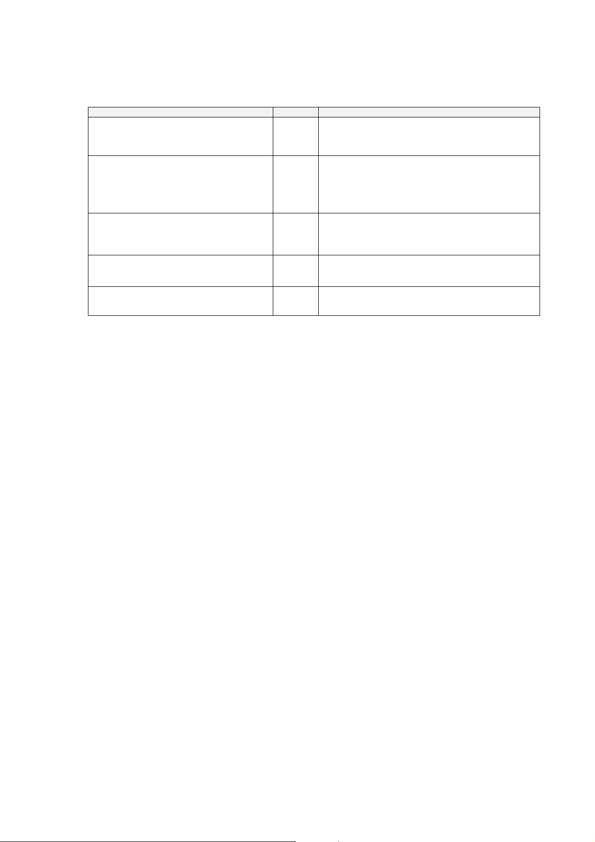
Manuals Related to the CX-Programmer
Name Cat. No. Contents
SYSMAC WS02-CXPC1-V8
CX-Programmer Operation Manual: SFC
SYSMAC WS02-CXPC1-V8
CX-Programmer Ver. 8.1 Operation
Manual
Function Blocks/Structured Texts
SYSMAC WS02-CXPC1-V8
CX-Programmer Ver. 8.1 Operation
Manual
CX-Integrator Operation Manual
CXONE-AL@@C-V3
CXONE-AL@@D-V3
CX-One Setup Manual
CXONE-AL@@C-V3
CXONE-AL@@D-V3
W469
(this
manual)
W447
W446 Describes the general CX-Programmer version 8.1
W464 Describes operating procedures for the CX-Integrator
W463 Installation and overview of CX-One FA Integrated
Explains how to use the SFC programming functions.
For explanations of other shared CX-Programmer
functions, refer to the CX-Programmer Operation
Manual (W446).
Describes the function block functions and structured
text programming functions that can be used with the
CX-Programmer version 8.1. For details on other
CX-Programmer functions, refer to the
CX-Programmer Ver. 8.1 Operation Manual (Cat. No.
W446).
operations that are not specifically related to SFC
programming, function block functions, and structured
text programming functions.
Network Configuration Tool for CS-, CJ-, CP-, and
NSJ-series Controllers.
Tool Package.
ix
Page 10

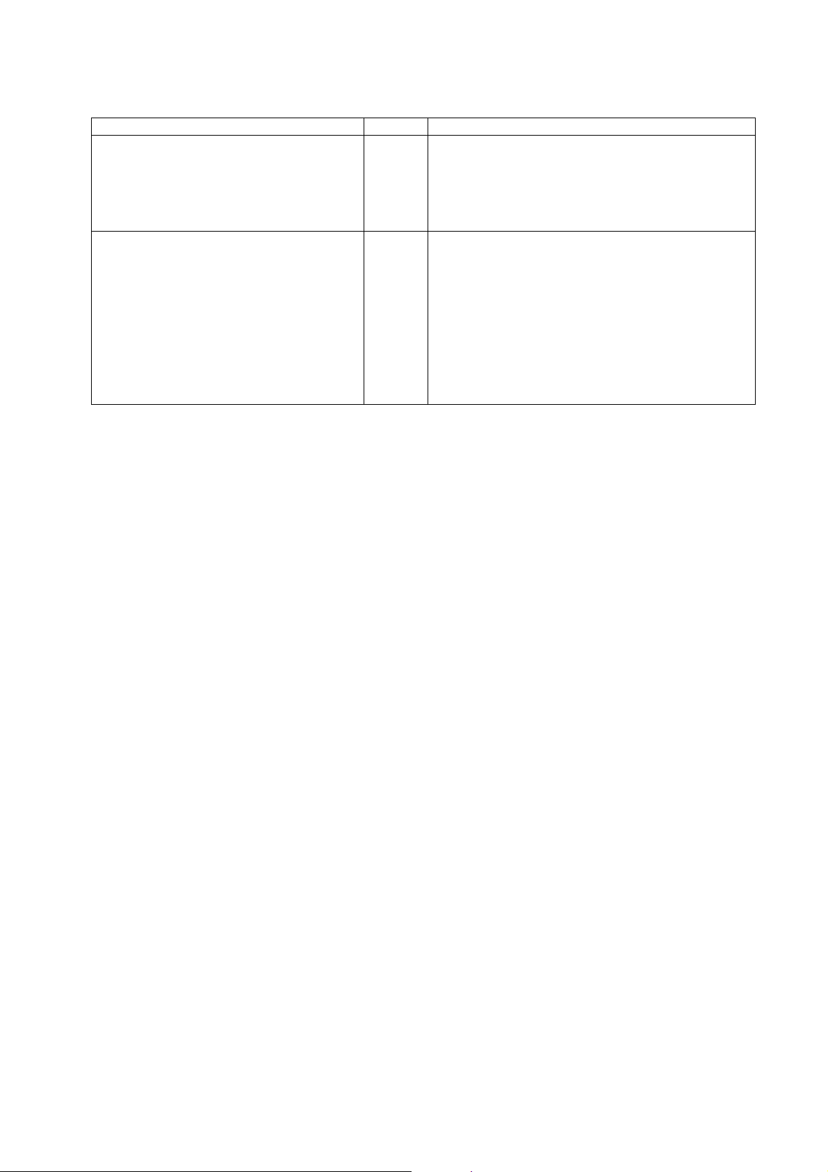
Manuals Related to the CJ2, CS1-H, CJ1-H, CJ1M PLCs
Name Cat. No. Contents
SYSMAC CJ Series
CJ2H-CPU6@-EIP, CJ2H-CPU6@
Programmable Controllers
Hardware User’s Manual
SYSMAC CJ Series
CJ2H-CPU6@-EIP, CJ2H-CPU6@
Programmable Controllers
Software User’s Manual
SYSMAC CS/CJ Series
CS1G/H-CPU@@-EV1, CS1G/H-CPU@@H,
CS1D-CPU@@H, CS1D-CPU@@S,
CJ2H-CPU6@-EIP, CJ2H-CPU6@,
CJ1H-CPU@@H-R
CJ1G-CPU@@, CJ1G/H-CPU@@H,
CJ1G-CPU@@P, CJ1M-CPU@@
SYSMAC One NSJ Series
NSJ@-@@@@ (B)-G5D
NSJ@-@@@@ (B)-M3D
Programmable Controllers
Instructions Reference Manual
SYSMAC CS Series
CS1G/H-CPU@@-EV1, CS1G/H-CPU@@H
Programmable Controllers
Operation Manual
SYSMAC CJ Series
CJ1G-CPU@@, CJ1G/H-CPU@@H,
CJ1G-CPU@@ P, CJ1M-CPU@@
Programmable Controllers
Operation Manual
SYSMAC CS/CJ Series
CS1G/H-CPU@@-EV1, CS1G/H-CPU@@H,
CJ1G-CPU@@, CJ1G/H-CPU@@H,
CJ1G-CPU@@P, CJ1M-CPU@@
Programmable Controllers
Programming Manual
W472 Provides an outline of and describes the design,
installation, maintenance, and other basic operations for
the CJ-series CJ2 CPU Units.
The following information is included:
Overview and features
System configuration
Installation and wiring
Troubleshooting
Use this manual together with the W473.
W473 Describes programming and other methods to use the
functions of the CJ2 CPU Units.
The following information is included:
CPU Unit operation
Internal memory areas
Programming
Tasks
CPU Unit built-in functions
Use this manual together with the W472.
W474 Describes the ladder diagram programming instructions
supported by CS/CJ-series or NSJ-series PLCs.
When programming, use this manual together with the
Operation Manual or Hardware User’s Manual (CS1:
W339, CJ1: W393,or CJ2:W472) and Programming
Manual or Software User’s Manual (CS1/CJ1:W394 or
CJ2:W473).
W339 Provides an outline of and describes the design,
installation, maintenance, and other basic operations for
the CS-series PLCs.
The following information is included:
An overview and features
The system configuration
Installation and wiring
I/O memory allocation
Troubleshooting
Use this manual together with the W394.
W393 Provides an outline of and describes the design,
installation, maintenance, and other basic operations for
the CJ-series PLCs.
The following information is included:
An overview and features
The system configuration
Installation and wiring
I/O memory allocation
Troubleshooting
Use this manual together with the W394.
W394 Describes programming and other methods to use the
functions of the CS/CJ-series PLCs.
The following information is included:
Programming
Tasks
File memory
Other functions
Use this manual together with the W339 or W393.
x
Page 11
Name Cat. No. Contents
SYSMAC CS/CJ Series
CS1G/H-CPU@@ -EV1, CS1G/H-CPU@@H,
CJ1G-CPU@@, CJ1G/H-CPU@@H,
CJ1G-CPU@@P, CJ1M-CPU@@
Programmable Controllers
Instructions Reference Manual
SYSMAC CS/CJ Series
CS1G/H-CPU@@-EV1, CS1G/H-CPU@@H,
CS1W-SCB21-V1/41-V1, CS1W-SCU21/41,
CJ2H-CPU6@-EIP, CJ2H-CPU6@,
CJ1G-CPU@@, CJ1G/H-CPU@@H,
CJ1G-CPU@@P, CJ1M-CPU@@,
CJ1W-SCU21-V1/41-V1
Communications Commands
Reference Manual
W340 Describes the ladder diagram programming instructions
supported by CS/CJ-series PLCs.
When programming, use this manual together with the
Operation Manual (CS1: W339 or CJ1: W393) and
Programming Manual (Cat. No. W394).
W342 Describes the communications commands that can be
addressed to CS/CJ-series CPU Units.
The following information is included:
C-series (Host Link) commands
FINS commands
Note: This manual describes commands that can be sent
to the CPU Unit without regard for the
communications path, which can be through a
serial communications port on the CPU Unit, a
communications port on a Serial Communications
Unit/Board, or a port on any other
Communications Unit.
xi
Page 12
Notice:
OMRON products are manufactured for use according to proper procedures by a qualified operator
and only for the purposes described in this manual.
The following conventions are used to indicate and classify precautions in this manual. Always heed
the information provided with them. Failure to heed precautions can result in injury to people or
damage to property.
DANGER
WARNING
Caution
Indicates an imminently hazardous situation which, if not avoided, will result in death
or serious injury. Additionally, there may be severe property damage.
Indicates a potentially hazardous situation which, if not avoided, could result in death
or serious injury. Additionally, there may be severe property damage.
Indicates a potentially hazardous situation which, if not avoided, may result in minor or
moderate injury, or property damage.
xii
Page 13
WARNING
Caution
Caution
Confirm safety thoroughly in advance when using the CX-Programmer to transfer any
I/O memory data to the actual PLC. Changes to the PLC’s I/O memory may result in
unexpected operation of devices connected to Output Units, regardless of the PLC’s
operating mode.
The following functions require particular caution when using the CX-Programmer to
transfer data to the CPU Unit’s I/O memory.
• Transferring data from the CX-Programmer to the CPU Unit’s CIO Area (with the
PLC Memory Window function)
• Transferring data from a Memory Card or EM file memory to the CPU Unit's CIO
Area (with the Memory Card Window function)
Confirm safety at the destination node before transferring a program to another node
or changing contents of the I/O memory area. Doing either of these without confirming
safety may result in injury.
Execute online editing only after confirming that no adverse effects will be caused by
extending the cycle time. Otherwise, the input signals may not be readable.
xiii
Page 14

Application Precautions
Observe the following precautions when using the CX-Programmer’s SFC functions.
• As a rule, the outputs of actions are reset when a step is changed from active status to
inactive status. When changing an output’s hold/reset setting, change the initial
setting or add reset processing as necessary. When making changes, verify the
operational timing of actions in the preceding and following steps.
Note: Refer to 1-5-1 Holding or Resetting an Action's Outputs and 1-5-2 Action Program
Precautions for details.
• Observe the following precautions before starting the CX-Programmer.
• Exit all applications not directly related to the CX-Programmer. Particularly exit
any software such as screen savers, virus checkers, E-mail or other
communications software, and schedulers or other applications that start up
periodically or automatically.
• Disable sharing hard disks, printers, or other devices with other computers on any
network.
• With some notebook computers, the RS-232C port is allocated to a modem or an
infrared line by default. Following the instructions in documentation for your
computer and enable using the RS-232C port as a normal serial port.
• With some notebook computers, the default settings for saving energy do not
supply the rated power to the RS-232C port. There may be both Windows settings
for saving energy, as well as setting for specific computer utilities and the BIOS.
Following the instructions in documentation for your computer, disable all energy
saving settings.
• Do not turn OFF the power supply to the PLC or disconnect the connecting cable
while the CX-Programmer is online with the PLC. The computer may malfunction.
• Confirm that no adverse effects will occur in the system before attempting any of the
following. Not doing so may result in an unexpected operation.
• Changing the operating mode of the PLC.
• Force-setting/force-resetting any bit in memory.
• Changing the present value of any word or any set value in memory.
• Check the user program for proper execution before actually running it on the Unit.
Not checking the program may result in an unexpected operation.
• When online editing is performed, the user program and parameter area data in CJ2,
CS1-H, CJ1-H, CJ1M, and CP1H CPU Units is backed up in the built-in flash memory.
The BKUP indicator will light on the front of the CPU Unit when the backup operation
is in progress. Do not turn OFF the power supply to the CPU Unit when the BKUP
indicator is lit. The data will not be backed up if power is turned OFF. To display the
status of writing to flash memory on the CX-Programmer, select Display dialog to
show PLC Memory Backup Status in the PLC properties and then select Windows –
PLC Memory Backup Status from the View Menu.
xiv
Page 15

Instructions for Use
Do not turn OFF the power supply to the computer while installing or uninstalling the
CX-Programmer. The data in a computer may be corrupted.
Description of Programmable Controllers
The abbreviation “PLC” means Programmable Controller. “PC” is used, however, in
some Programming Device displays to mean Programmable Controller.
xv
Page 16

Page 17

SECTION 1
Overview
1-1 SFC Overview.............................................................................................................2
1-1-1 SFC Overview...................................................................................................................2
1-1-2 CX-Programmer Features.................................................................................................3
1-2 CX-Programmer Specifications...................................................................................6
1-2-1 PLC Models Supporting SFC............................................................................................6
1-2-2 Specifications....................................................................................................................6
1-3 Window Components..................................................................................................8
1-3-1 SFC Editor ........................................................................................................................8
1-3-2 Menus..............................................................................................................................11
1-3-3 SFC Editor Pop-up Menu................................................................................................14
1-3-4 Toolbar Icons..................................................................................................................21
1-3-5 Keyboard Shortcuts.........................................................................................................22
1-3-6 Environmental Settings Unique to the SFC Programming Functions.............................23
1-4 SFC Programming Example......................................................................................27
1-4-1 Simple Example of an SFC Program..............................................................................27
1-4-2 Procedures for Using CX-Programmer...........................................................................30
1-5 Precautions When Creating SFC Programs...............................................................33
1-5-1 Holding or Resetting an Action’s Outputs......................................................................33
1-5-2 Action Program Precautions ...........................................................................................34
1-5-3 Precautions for Transition Programs...............................................................................36
1-5-4 Ladder Language Instructions That Cannot Be Used in Action Programs and Transition
Programs.........................................................................................................................37
1-5-5 Task Allocation...............................................................................................................37
1-5-6 Memory Allocation.........................................................................................................38
1-5-7 Subchart Online Editing Function Restrictions...............................................................39
1
Page 18
SFC Overview Section 1-1
1-1 SFC Overview
1-1-1 SFC Overview
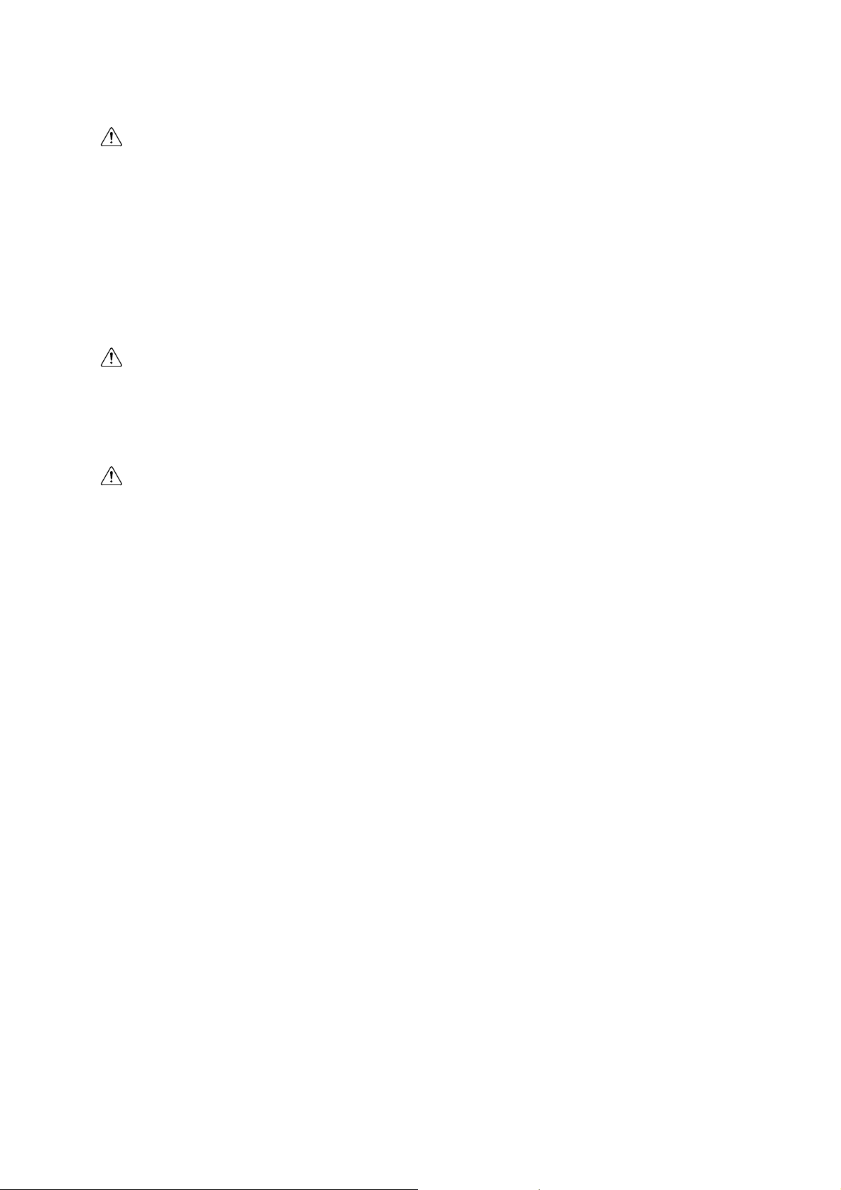
The SFC (Sequential Function Chart) language is a graphical programming language
developed to facilitate the description of step progression programs, which mainly
control sequential processes.
SFC, with its graphical representation of step flow and with description of the
conditions for step progression and the actions in each step, allows users to program
the control of sequential processes.
Step1
Step2
Step3
SFC offers the following advantages.
Since step flow and program control correspond, even third-party programmers can
easily understand the program, as a whole. This reduces the program debugging and
maintenance workload.
Processing Contents
Step Transition Condition
Processing Contents
Step Transition Condition
Processing Contents
Step Transition Condition
Process Flow
A
Equipment Control/
External Device Control
B
C
Correspond-
ence
Step A
Step C
SFC Program
Step B
Programs can be created separately for each step, without the need to consider
complicated requirement exchanges between steps. In other words, each step can be
programmed separately, by a different developer, making program development
simpler and more efficient.
2
Page 19
SFC Overview Section 1-1
Step1
Step2
Step 3
Processing Contents
Processing Contents
Processing Contents
Programs are independently completed for each step, and are therefore simple to
reuse.
Processing is performed on a per step basis, giving process time, only to active steps,
and not to inactive steps, allowing the CPU unit cycle time to be shortened.
1-1-2 CX-Programmer Features
The CX-Programmer Support Software is equipped with an SFC editor, and can be
used to create, monitor, and debug SFC programs for CS/CJ-series and CJ2-series
PLCs. The CX-Programmer supports SFC language in addition to conventional ladder
and structured text (ST) programming languages.
With desirable features, such as the user interface, carried over from the earlier series,
and with the added SFC programming function, the CX-Programmer provides a
programming environment that can take full advantage of the SFC language’s features.
Combining SFC, Ladder, and ST for User Programs
Each program allocated to a task can be coded as an arbitrary combination of SFC,
ladder, and ST. Hence, the language best suited to each process can be utilized (e.g.
SFC for step progression, ladder for device control, and ST for mathematical
processes).
The common functions of CX-Programmer are still available to use, regardless of the
language used.
Developed by
“A”
Developed by
“B”
Developed by
“C”
Steps can be
developed separately.
User Program
Ta sk
Ta sk
Ta sk
Ta sk
SFC
Step Progression
Control
Programming
Language Best
Suited to the
Process is
Selectable
a = a + 1
Ladder
Device Control
ST
Mathematical
Processes
3
Page 20
SFC Overview Section 1-1
A
A
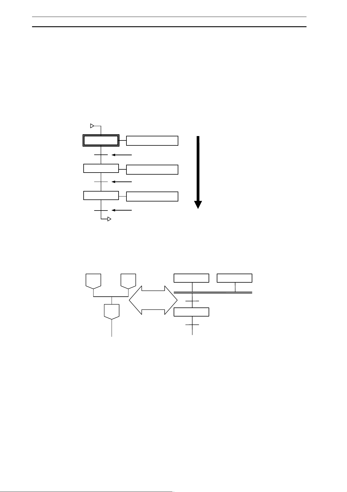
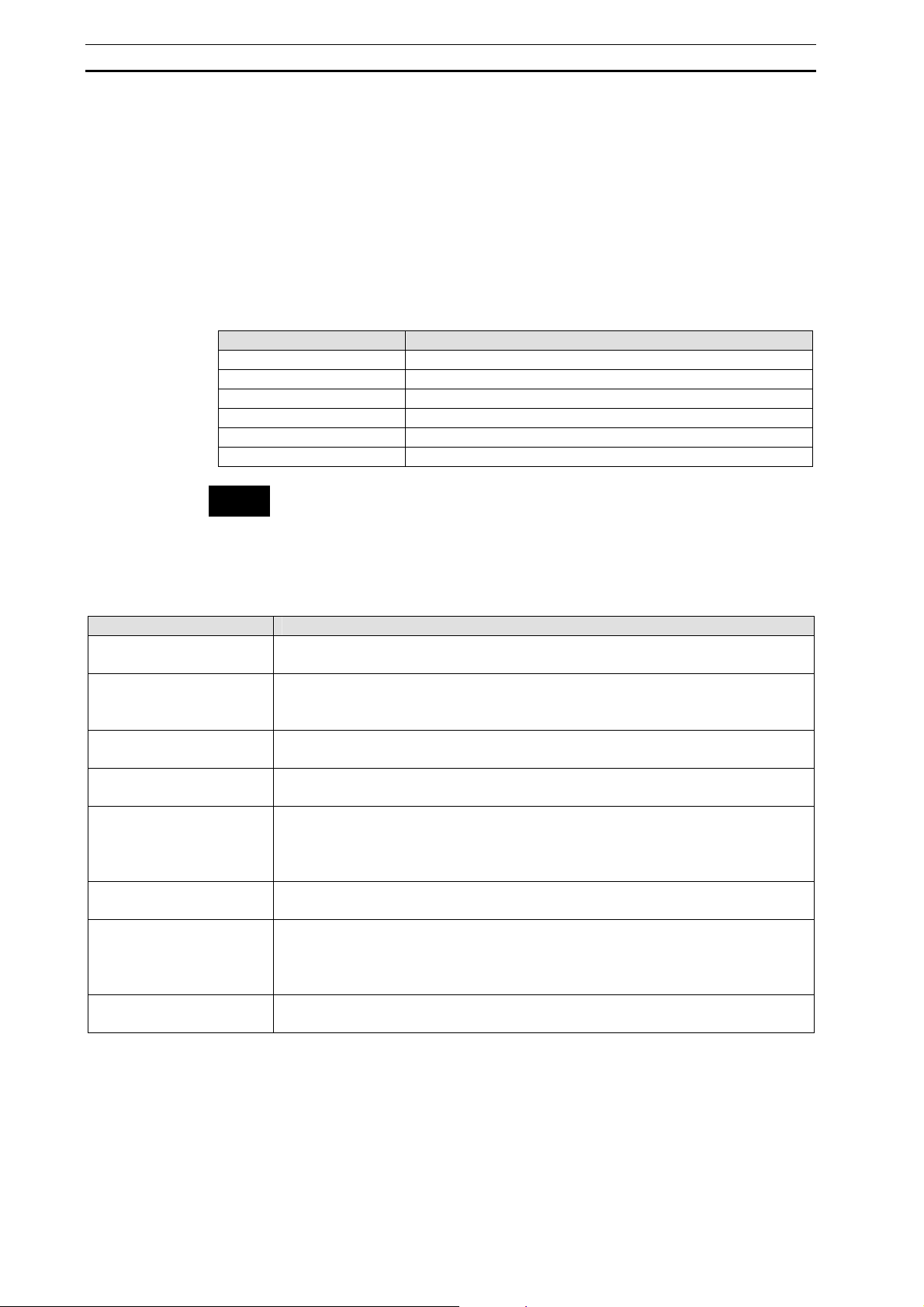
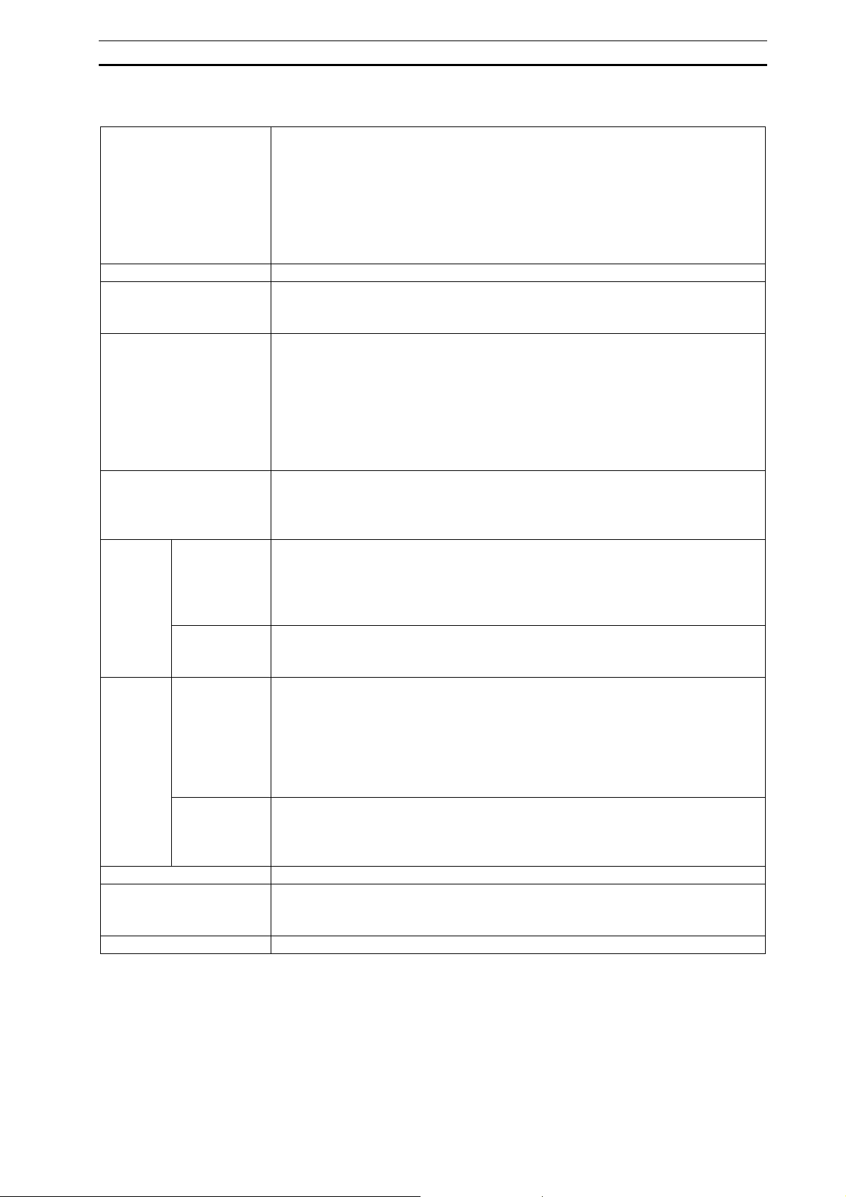
Ladder and ST as Part of SFC Programs
The step actions and transition conditions within an SFC program can be coded in
either ladder or ST.
The step actions and transition conditions coded in ladder or ST are registered in an
SFC program as action programs and transition programs.
ction Programs (Ladder)
ction Programs (ST)
Transition Program (Ladder)
Transition Program (ST)
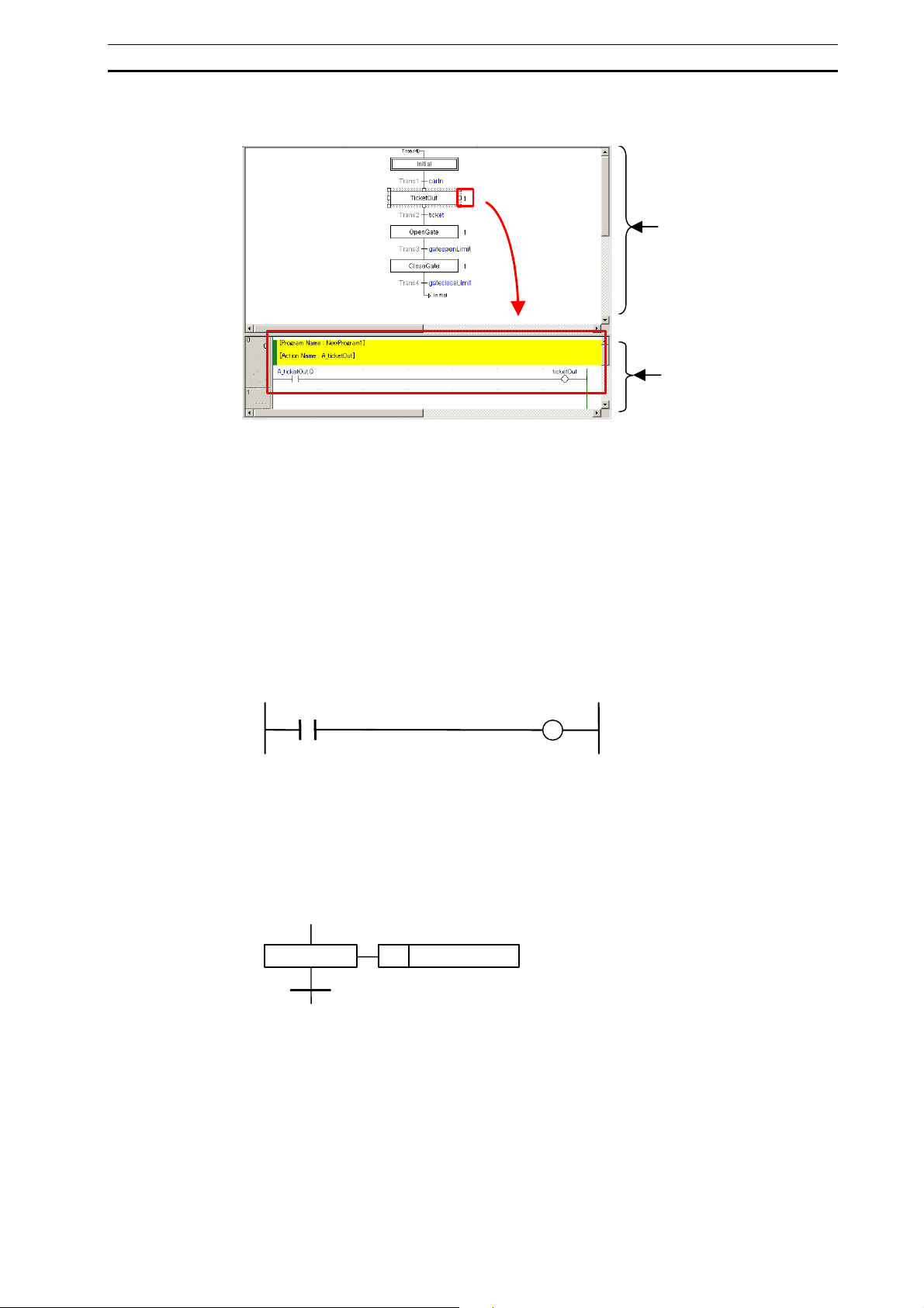
Simultaneous Display/Editing of SFC Charts and Action/Transition Programs
The SFC chart editor can display the SFC view and program view in a horizontally or
vertically split window, allowing an SFC chart and action block (or transition program)
to be viewed and edited at the same time.
In addition, action blocks can be hidden in the SFC view, but action programs and
transition programs can be viewed and edited in the program view, even when the
action blocks are hidden in the SFC chart. Processing contents and transition
conditions can be viewed and edited while envisioning the entire program picture,
allowing the features of SFC to be fully realized.
Action Blocks Shown
SFC View
Program View
4
Page 21
SFC Overview Section 1-1
Action Blocks Hidden
SFC View
Program View
Online Editing and Debugging
SFC charts can be edited online. Furthermore, action blocks can be hidden while
debugging, and the step progression status can be checked. The SFC chart editor will
display the action programs in the program view, even while the action blocks are
hidden.
Array Variables
Array variables can be used in ST and SFC, in addition to being able to use them in
conventional ladder programs, executed for tasks in CX-Programmer.
Ladder
ST
b[7] := a[7]
SFC
a[5] b[5]
NStep n a[3]
b[3]
5
Page 22
CX-Programmer Specifications Section 1-2
1-2 CX-Programmer Specifications
This section describes the CX-Programmer’s operating environment in which SFC
functions can be used. For details on the basic CX-Programmer operating environment,
refer to the CX-Programmer Operation Manual (Cat. No. W446).
1-2-1 PLC Models Supporting SFC
The following PLCs (Programmable Logic Controllers) support the SFC language.
PLC model CPU model
CJ2H unit version 1.0 or later CJ2H-CPU68/67/66/65/64/68-EIP/67-EIP/66-EIP/65-EIP/64-EIP
CS1G-H unit version 4.0 CS1G-CPU45H/44H/43H/42H
CS1H-H unit version 4.0 CS1H-CPU67H/66H/65H/64H/63H
CJ1G-H unit version 4.0 CJ1G-CPU45H/44H/43H/42H
CJ1H-H unit version 4.0 CJ1H-CPU67H/66H/65H/67H-R/66H-R/65H-R/64H-R
CJ1M unit version 4.0 CJ1M-CPU23/22/21/13/12/11
Note
• SFC cannot be used on CP-series PLCs.
• Microsoft .Net Framework 1.1 or later must be installed.
• Internet Explorer 5.@ or later must be installed.
1-2-2 Specifications
Item Details
Programming language for
tasks
SFC program unit Tasks (1 task = 1 SFC chart)
Tasks supported for SFC
program allocation
SFC elements Steps, transitions, actions, jumps, subcharts
SFC chart shapes Series, divergence/convergence, simultaneous sequence divergence/convergence, jump
Step status Active, inactive
Transitions * Boolean address bits (Boolean variables or actual addresses), ST expressions, or
Transition program transition
conditions
SFC, ladder, or ST
(In any combination)
CJ2: 384 tasks max. (128 cyclic tasks, 256 extra tasks)
Other models: 288 tasks max. (32 cyclic tasks, 256 extra tasks)
Cyclic or extra tasks
Note: SFC elements are automatically registered to local variables.
Note: Number of divergences/convergences, simultaneous sequence
divergences/convergences, and subcharts are unlimited. (Unlike with SFC for CV
series)
Note: PAUSE and HALT are not supported. (Unlike with SFC for CVM1/CV series)
transition programs
Note 1: A ladder or ST program can be used for a transition program.
Note 2: Function blocks can be used for transition programs.
A transition condition is met when the Boolean variable with the same name as the
transition program is switched to “ON”.
6
Page 23
CX-Programmer Specifications Section 1-2
Action blocks Action Qualifiers (AQ) (11 types) + action
Note 1: There is no restriction on the number of action blocks allocated to a step.
Note 2: If there are multiple action programs in the same step, the execution order is
determined by the order (top to bottom) that the action programs are listed in the
project workspace.
Note 3: An action program is executed just once per cycle (unlike the CV-series SFC
operation), even if the action program is used in multiple steps and the multiple
steps are active at the same time.
Action qualifiers (11 types) N, P, P1, P0, L, D, R, S, SL, SD, DS
Actions * Boolean address bits (Boolean variables or actual addresses) or action programs
Note 1: A ladder or ST program can be used for an action program.
Note 2: Function blocks can be used for action programs.
Output reset When a step has become inactive, the action block’s outputs can be reset by any one of
the following methods. Select the output reset in the action’s properties (unless the action
is Boolean or an ST program).
The reset operation depends upon the type of program added, as follows.
• Specified bit: Reset.
• Ladder program: The default setting is to reset outputs. If you do not want the outputs
reset, specify that in the action program’s properties.
• ST program: Not reset.
Direct addressing An actual address can be specified for an action or transition using an SFC chart’s
Boolean action/transition or a ladder program.
Only variables can be used to specify addresses in ST programs. (Direct addressing is not
possible.)
Step
control
SFC task
control
Force Step Transitions can be force-set/force-reset online, for a step-by-step execution.
Online Editing Allows SFC chart editing, actions addition/deletion, and transitions addition/deletion.
Array variables Array variables are supported for SFC, ladder, and ST programs.
Step activation/
deactivation
Step timer
readings/
updates
Executing and
ending SFC
tasks
Stopping SFC
tasks (output
reset or output
hold)
* The maximum number of transition programs, action programs, and subcharts is as follows
(when using function blocks, number of definitions are included):
CJ2 CPU Units: 2,048 max.
CS1H /CJ1H CPU Units: 1024 max.
CJ1M CPU Units: 256 max.
Steps in an SFC chart can be activated or deactivated from the following ladder programs
(by using the “SA” step activation instruction and the “SE” step deactivation instruction).
* Ladder program outside of SFC programs
* Action ladder program within an SFC program
* Action ladder program within another SFC program
Time elapsed since the activation of a step can be read and updated (by using the “TSR”
read step timer value instruction and the “TSW” set step timer value instruction).
0 to 6553.5 sec (Unit: 100 millisecond), or 0 to 65535 sec (Unit: 1 sec)
The execution and ending of SFC tasks can be controlled from the ladder program with
the SFC Task Control Instructions.
Execute: If the SFC task was completed, the SFC task status is completely reset and
execution proceeds from the initial step.
If the SFC task was stopped, the SFC task is executed from the step where the
task was stopped.
End: The status of outputs is held, and the SFC task is ended.
SFC tasks can be stopped (outputs reset or outputs held) from the ladder program with the
SFC Task Control Instructions.
Output reset: Resets the outputs, and pauses the SFC task.
Output hold: Retains the output status, and pauses the SFC task.
Note: Choose between standard mode (transfer with source code) and quick mode
(transfer without SFC source code).
7
Page 24
Window Components Section 1-3
1-3 Window Components
This section describes the CX-Programmer’s SFC chart editing functions and functions
related to the SFC editor. For details on other functions, refer to the CX-Programmer
Operation Manual (Cat. No. W446).
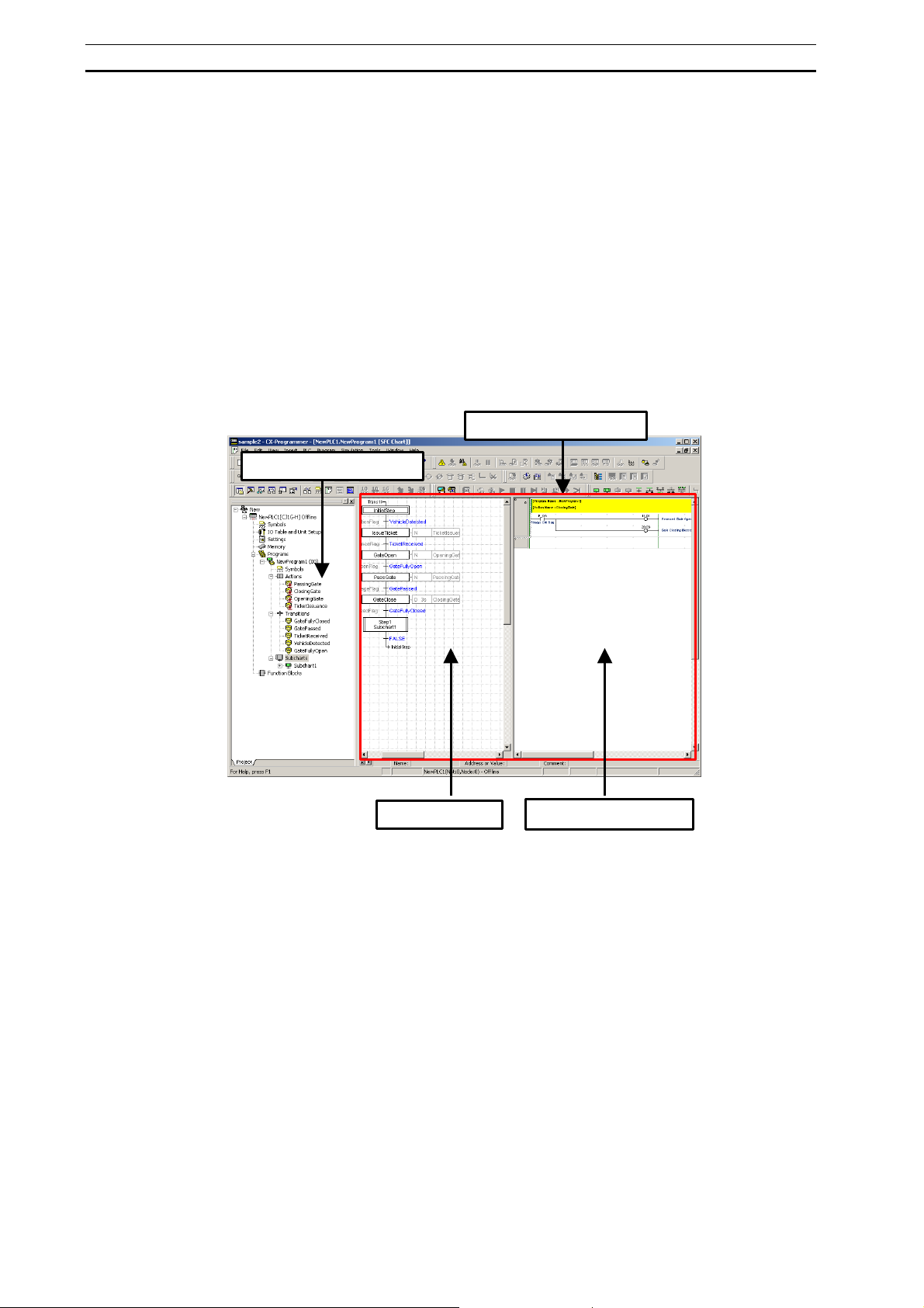
1-3-1 SFC Editor
SFC elements can be inserted and connected in the CX-Programmer’s SFC editor to
create sequential step programs. The project workspace and SFC editor can be
displayed in a horizontally or vertically split window, so that the structural relationship
between the SFC chart and action block (or transition program) can be clearly
understood.
SFC Editor
Project Workspace
SFC View
Program View
8
Page 25
Window Components Section 1-3
A
(
)
r
g
A
r
r
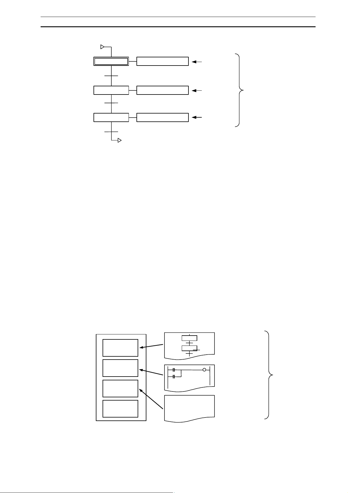
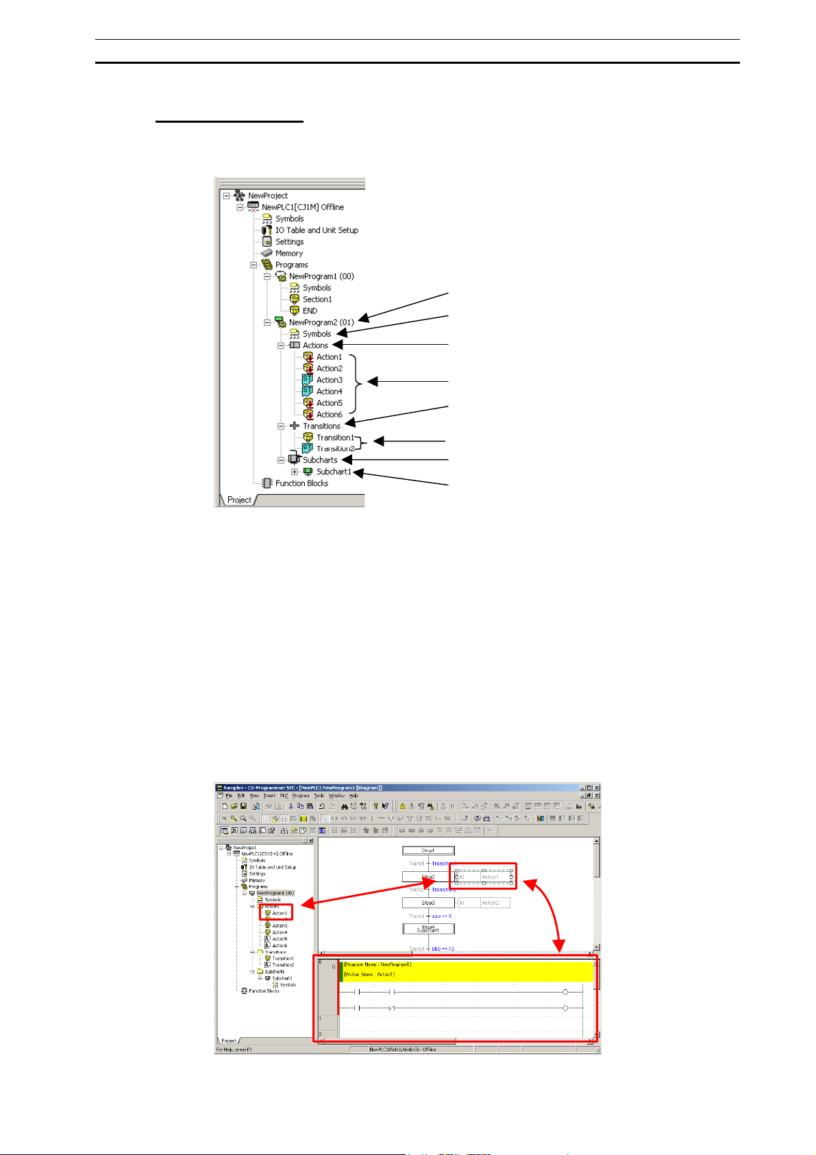
Project Workspace
SFC programming elements are hierarchically displayed and managed.
The Project Workspace is also known as the Project Tree.
SFC Pro
Local Variable
Transition Folde
Transition Programs
(Ladder or ST)
Subchart Folde
Subchart Programs
ram
ction Folde
ction Programs
Ladder or ST
SFC Programs
SFC programs are registered as child items of the Programs folder in the project
workspace. Task allocation is required to execute the SFC program.
Symbol Tables
Variables are automatically registered in the symbol table, corresponding to the SFC
elements created in the SFC chart. The variables registered here are used as local
variables in the SFC chart. Also, the user can register the variables that are required
while writing the SFC program.
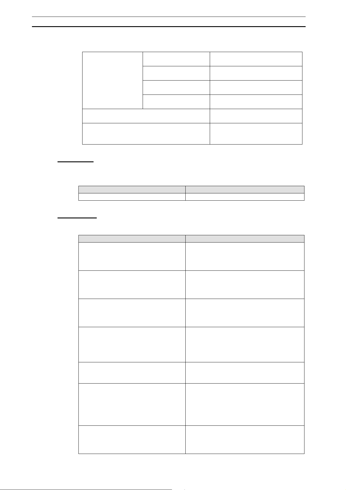
Actions Folder and Action Programs
Action programs are registered in the Actions folder under the SFC program structure.
An action program describes the step actions in ladder or ST.
Action programs are associated to an action block within an SFC chart by selecting the
relevant action name.
9
Page 26
Window Components Section 1-3
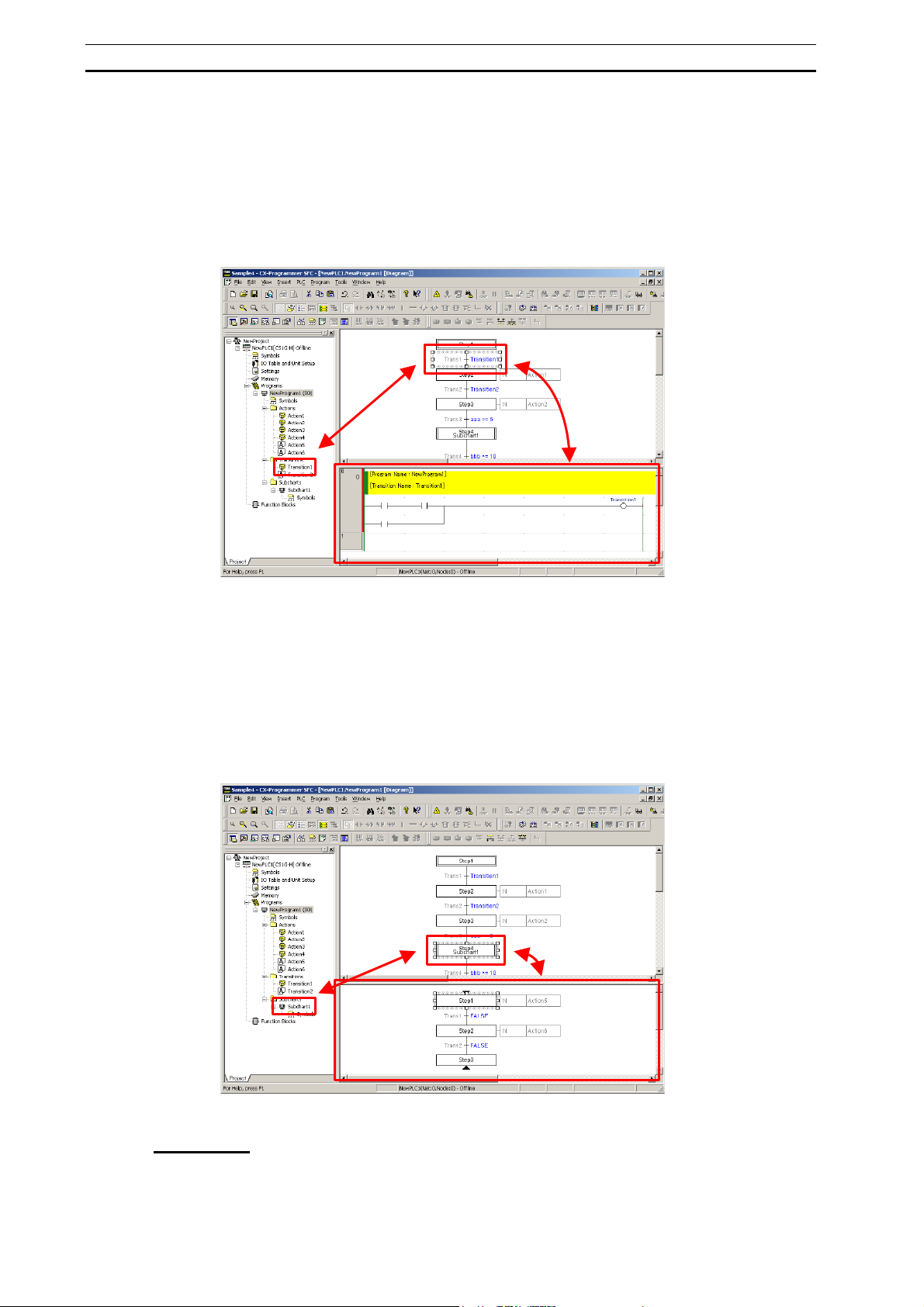
Transitions Folder and Transition Programs
Transition programs are registered in the Transitions folder under the SFC program.
A transition program describes the step progression conditions, which need to be
expressed by multiple input signals or by the more complex ladder or ST logic.
Transition programs are associated with an SFC chart’s transition by selecting the
same transition name.
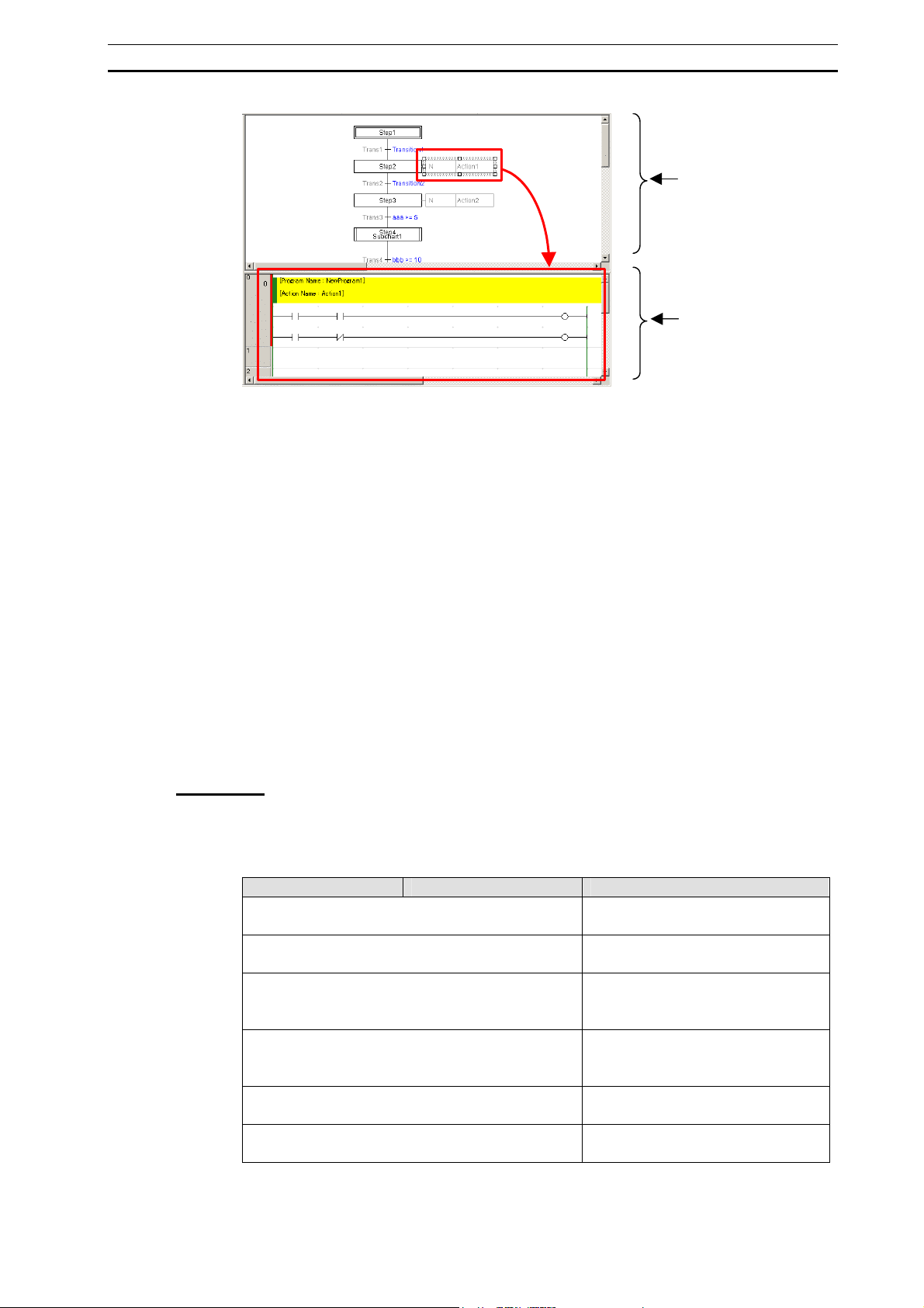
Subcharts Folder and Subchart Programs
Subchart programs are registered in the Subcharts folder under the SFC program.
A subchart program allows an SFC program with large-scale step progression control
to be developed in parts, improving the reusability and visibility of the program and
allowing for more structured programming of the SFC program.
Subchart programs are subcharts for SFC charts and are associated with an SFC chart
by selecting the same subchart name. In program view, it is possible to check whether
an SFC subchart is a partial SFC chart of the SFC program.
10
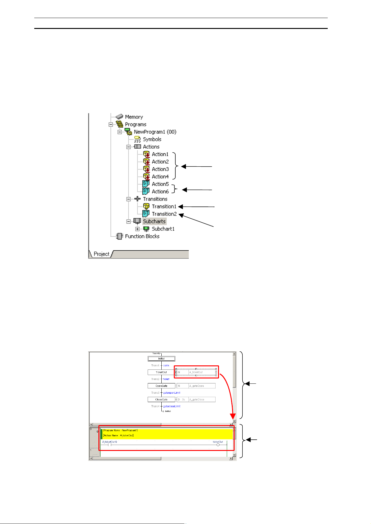
SFC Editor
Displays an SFC chart or subchart.
By providing a split SFC view and program view display, the SFC chart can be viewed
simultaneously with the associated action program or transition program.
Page 27
Window Components Section 1-3
SFC View
Program View
SFC Editor Display Customization
Select Tools - Options from the menu, and then the Appearance or SFC tab to
customize the SFC editor display.
For details on customizing the SFC editor display, refer to 1-3-6 Environmental
Settings Unique to the SFC Programming Functions.
SFC View
Displays an SFC chart or subchart.
Program View
Displays the action program, transition program, or subchart for the action block,
transition, or subchart step, selected in the SFC view.
The action program, transition program, or subchart program can be edited in program
view, while viewing the SFC chart in the SFC editor.
1-3-2 Menus
Edit Menu
This menu is displayed when the SFC editor is displayed in the main editing window
and has the cursor focus. Menu items are enabled and disabled depending on which
SFC element is selected in the SFC editor.
Edit Step Name Enables editing of the selected step
Edit Transition Condition Enables editing of a selected transition
Edit Action Name Displays a combo box in the selected
Edit Action Qualifier Displays a combo box in the action
Edit Action Qualifier Time Enables editing of the selected action
Edit Action Indicator Variable Enables editing of the selected action
Menu Sub-Menu Function
name.
name.
action block, enabling selection of the
action program name.
qualifier of the selected action block,
enabling action qualifier selection.
block’s action qualifier timer.
block’s indicator variable.
11
Page 28
Window Components Section 1-3
Edit Connections
Tidy Element Positions Arranges all of the elements in the SFC
Tidy Descendant Element Positions Arranges the SFC chart elements
Add Connection To SFC
Element
Add Connection From SFC
Element
Delete Connection To SFC
Element
Delete Connection From
SFC Element
Draws out a connection from the
topside of the selected SFC element.
Draws out a connection from the
downside of the selected SFC element.
Deletes the connection on the topside
of the selected SFC element.
Deletes the connection on the
downside of the selected SFC element.
chart.
positioned after the selected SFC
element.
View Menu
This menu is enabled only when the display magnifier for the SFC editor has been
changed.
Menu Function
Zoom Reset Resets the scaling ratio of the SFC editor to 100%.
Insert Menu
This menu is enabled only when the SFC editor is displayed.
Step When a bottom transition is selected, this item adds
Subchart Step When a bottom transition is selected, this item adds
Transition When a bottom step is selected, this item adds a
Divergences When a bottom step is selected, this item adds a
Convergences When a conditionally-branched bottom transition is
Simultaneous Sequence Divergences When a bottom transition is selected, this item adds
Simultaneous Sequence Convergences When a parallel-branched bottom step is selected,
Menu Function
a step and connects it to the transition.
When a transition is not selected, it inserts an
independent step.
a subchart step and connects it to the transition.
When a transition is not selected, it inserts an
independent subchart step.
transition and connects it to the step.
When a step is not selected, it inserts an
independent transition.
divergence and 2 transitions, and connects them to
the step.
When a step is not selected, it adds a step, a
divergence, and 2 transitions.
selected, this item adds a convergence and a step,
and connects them to the transition.
a simultaneous sequence divergence and 2 steps,
and connects them to the transition.
When a transition is not selected, it adds a
transition, a simultaneous sequence divergence,
and 2 steps.
this item adds a simultaneous sequence
convergence and a transition, and connects them to
the step.
12
Page 29
Window Components Section 1-3
Step and Transition When a bottom transition is selected, this item adds
a step and a transition, and connects them to the
transition.
Transition and Step When a bottom step is selected, this item adds a
transition and a step, and connects them to the
step.
Simultaneous Convergent Step Above Inserts a step on the topside of a simultaneous
sequence convergence.
Convergent Transition Above Inserts a transition on the topside of a convergence.
Connector Draws a connection from an SFC element that does
not have a connection in the SFC chart.
Program Menu
This menu is enabled only when the SFC editor is displayed.
Menu Function
Online Edit
Transfer SFC/ST Source to
PLC (Online Edit)
Release FB/SFC/ST,
Online Edit Access Rights
When an SFC program revision is being transferred
in quick mode during online SFC chart editing, only
the SFC source code is transferred later.
Makes PLC access rights invalid in the event of
process interruption, due to communication error
during online SFC chart editing.
13
Page 30
Window Components Section 1-3
1-3-3 SFC Editor Pop-up Menu
This section describes menus, which are displayed by right-clicking within the SFC
editor.
The menu displayed depends on which SFC element is selected. Furthermore, menu
items are enabled and disabled depending on the connected state of SFC elements.
Right-Clicking a Step
The step elements menu for working online differs from that for working offline.
Offline Pop-Up Menu
Menu Sub-Menu Function
Edit Step Name Enables editing of the selected step
name.
Step Type
Step Timer
Add Action
Show Action Blocks Shows hidden action blocks.
Add Transition and Step Adds a transition and a step, and
Add Transition Adds a transition and connects it to the
Insert Step and Transition Above Adds a transition and a step, and
Insert Transition Above Adds a transition to the topside of the
Add Divergences Adds a divergence and 2 transitions,
Add Simultaneous Sequence Convergence Adds a simultaneous sequence
Normal Changes the selected step to a normal
step.
Initial Changes the selected step to an initial
step.
Entry Changes the selected step to a entry
step.
Return Changes the selected step to a return
step.
Use Millisecond Timer Sets the step timer unit to 100
milliseconds.
Use Second Timer Sets the step timer unit to 1 second.
Boolean Action Adds a Boolean variable or actual
address to the selected step.
New Ladder Action Creates a new ladder program, and
adds it to the selected step.
New Structured Text
Action
Existing Action Adds an already registered action to
Creates a new ST program, and adds it
to the selected step.
the selected step.
connects them to the selected step.
selected step.
connects them to the topside of the
selected step.
selected step.
and connects them to the selected
step.
convergence and a transition, and
connects them to the selected step.
14
Page 31

Window Components Section 1-3
Connections
Open Subchart Definition Opens a subchart.
Cut Cuts the selected step to the clipboard.
Copy Copies the selected step to the
Paste Pastes the contents of the clipboard.
Delete Deletes the selected step.
Tidy Descendant SFC Elements Arranges elements of the SFC chart
Online Pop-Up Menu
Menu Sub-Menu Function
Force Step
Set Step Timer Value Updates the step timer value.
Open Subchart Definition Opens a subchart.
Show Action Blocks Shows hidden action blocks.
Tidy Descendant SFC Elements Arranges elements of the SFC chart
Add Connection Opens the Add Connection dialog.
Add Jump to Step Draws out a connection from the
topside of the selected step, and
connects it to the downside of the
transition that is to become the jump
starting point.
Add Connection To Step Draws out a connection from the
topside of the selected step, and
connects it to the downside of a
transition.
Delete Connection To Step Deletes the connection on the topside
of the selected step.
Draw Connections to Step
as Jump
Add Connection From Step Draws out a connection from the
Delete Connection From
Step
On Activates the selected step.
Off Deactivates the selected step.
Cancel Cancels the forced status.
Changes the topside of the selected
step to a jump.
downside of the selected step, and
connects it to the topside of a transition.
Deletes the connection on the
downside of the selected step.
clipboard.
positioned after the selected step.
positioned after the selected step.
Right-Clicking a Transition
The transition elements menu for working online differs from that for working offline.
Offline Pop-Up Menu
Menu Sub-Menu Function
Edit Transition Condition Enables editing of the selected
Add Step and Transition Adds a step and a transition, and
Add Step Adds a step and connects it to the
Insert Transition and Step Above Adds a transition and a step, and
transition condition.
connects them to the selected
transition.
selected transition.
connects them to the topside of the
selected transition.
15
Page 32

Window Components Section 1-3
Insert Step Above Adds a step to the topside of the
selected transition
Add Convergence Adds a convergence and a step, and
connects them to the selected
transition.
Add Simultaneous Sequence Divergence Adds a simultaneous sequence
divergence and 2 steps, and connects
them to the selected transition.
Connections
Add Subchart Step
Open Transition Definition Opens the selected transition program.
Add Connection Opens the Add Connection dialog.
Add Jump From Transition Draws out a connection from the
downside of the selected transition, and
connects it to the topside of the step
that is to become the jump destination.
Add Connection From
Transition
Delete Connection From
Transition
Draw Connections From
Transition as Jump
Add Connection To
Transition
Delete Connection To
Transition
New Subchart Creates and adds a new subchart, and
Existing Subchart Connects an already registered
Draws out a connection from the
downside of the selected transition, and
connects it to the topside of a step.
Deletes the connection on the topside
of the selected transition.
Changes the topside of the selected
transition to a jump.
Draws out a connection from the
topside of the selected isolated
transition, and connects it to the
downside of a step.
Deletes the connection on the
downside of the selected transition.
connects it to the selected transition as
a subchart step.
subchart to the selected transition as a
subchart step.
Cut Cuts the selected transition to the
clipboard.
Copy Copies the selected transition to the
clipboard.
Paste Pastes the contents of the clipboard.
Delete Deletes the selected transition.
Tidy Descendant SFC Elements Arranges SFC chart elements
positioned after the selected transition.
Online Pop-Up Menu
Menu Sub-Menu Function
Force Step
Open Transition Definition Displays the selected transition
Tidy Descendant SFC Elements Arranges SFC chart elements
On Sets the transition condition to ON.
Off Sets the transition condition to OFF.
Cancel Cancels the forced status.
program.
positioned after the selected transition.
16
Page 33

Window Components Section 1-3
Right-Clicking a Divergence
Menu Sub-Menu Function
Add Divergent Transition Branch Adds a transition to the right side of the
selected divergence.
Insert Step Above Adds a step and connects it to the
topside of the selected divergence.
Insert Transition and Step Above Adds a transition and a step, and
connects them to the topside of the
selected divergence.
Connections
Use Default Transition Precedence The order of execution can be set by
Cut Cuts the selected divergence to the
Copy Copies the selected divergence to the
Paste Pastes the contents of the clipboard.
Delete Deletes the selected divergence.
Tidy Descendant SFC Elements Arranges elements of the SFC chart
Add Connection Opens the Add Connection dialog.
Add Connection To
Divergence
Add Connection From
Divergence
Delete Connection To
Divergence
Delete Connection From
Divergence
Draws out a connection from the
topside of the selected divergence, and
connects it to the downside of a step.
Draws out a connection from the
downside of the selected divergence,
and connects it to the topside of a
transition.
Deletes the connection on the topside
of the selected divergence.
Deletes the connection on the
downside of the selected divergence.
deselecting (removing the check
marks) items. (By default, the execution
order is from left to right, and numbers
are not displayed.)
clipboard.
clipboard.
positioned after the selected
divergence.
Right-Clicking a Convergence
Menu Sub-Menu Function
Add Convergent Transition Branch Adds a transition to the right side of the
Add Step Adds a step and connects it to the
Add Subchart Step
Add Step and Transition Adds a step and a transition, and
New Subchart Creates and adds a new subchart, and
Existing Subchart Connects an already registered
selected convergence.
selected convergence.
connects it to the selected convergence
as a subchart step.
subchart to the selected convergence
as a subchart step.
connects them to the selected
convergence.
17
Page 34

Window Components Section 1-3
Connections
Cut Cuts the selected simultaneous
Copy Copies the selected simultaneous
Paste Pastes the contents of the clipboard.
Delete Deletes the selected convergence.
Tidy Descendant SFC Elements Arranges SFC chart elements
Add Connection Opens the Add Connection dialog.
Add Connection To
Convergence
Add Connection From
Convergence
Delete Connection To
Convergence
Delete Connection From
Convergence
Draws out a connection from the
topside of the selected convergence,
and connects it to the downside of a
transition.
Draws out a connection from the
downside of the selected convergence,
and connects it to the topside of a step.
Deletes all connections on the topside
of the selected convergence.
Deletes the connection on the
downside of the selected convergence.
sequence divergence to the clipboard.
sequence divergence to the clipboard.
positioned after the selected
Convergence.
Right-Clicking a Simultaneous Sequence Divergence
Menu Sub-Menu Function
Add Simultaneous Divergent Step Branch Adds a step to the right side of the
selected simultaneous sequence
divergence.
Insert Transition Above Adds a transition to the topside of the
selected simultaneous sequence
divergence.
Insert Step and Transition Above Adds a step and a transition, and
connects them to the topside of the
selected simultaneous sequence
divergence.
Connections
Cut Cuts the selected simultaneous
Copy Copies the selected simultaneous
Paste Pastes the contents of the clipboard.
Delete Deletes the selected simultaneous
Tidy Descendant SFC Elements Arranges SFC chart elements
Add Connection Opens the Add Connection dialog.
Add Connection To
Divergence
Add Connection From
Divergence
Delete Connection To
Divergence
Delete Connection From
Divergence
Draws out a connection from the
topside of the selected simultaneous
sequence divergence, and connects it
to the downside of a transition.
Draws out a connection from the
downside of the selected simultaneous
sequence divergence, and connects it
to the downside of a step.
Deletes the connection on the topside
of the selected simultaneous sequence
divergence.
Deletes the connection on the
downside of the selected simultaneous
sequence divergence.
sequence divergence to the clipboard.
sequence divergence to the clipboard.
sequence divergence.
positioned after the selected
simultaneous sequence divergence.
18
Page 35

Window Components Section 1-3
Right-Clicking a Simultaneous Sequence Convergence
Menu Sub-Menu Function
Add Simultaneous Sequence Convergent Step Branch Adds a step and connects it to the
topside of the selected simultaneous
sequence convergence.
Add Transition Adds a transition and connects it to the
selected simultaneous sequence
convergence.
Add Transition and Step Adds a transition and a step, and
connects them to the selected
simultaneous sequence convergence.
Connections
Cut Cuts the selected simultaneous
Copy Copies the selected simultaneous
Paste Pastes the contents of the clipboard.
Delete Deletes the selected simultaneous
Tidy Descendant SFC Elements Arranges SFC chart elements
Add Connection Opens the Add Connection dialog.
Add Connection To
Convergence
Add Connection From
Convergence
Delete Connection To
Convergence
Delete Connection From
Convergence
Draws out a connection from the
topside of the selected simultaneous
sequence convergence, and connects
it to the downside of a step.
Draws out a connection from the
downside of the selected simultaneous
sequence convergence, and connects
it to the topside of a transition.
Deletes all connections on the topside
of the selected simultaneous sequence
convergence.
Deletes the connection on the
downside of the selected simultaneous
sequence convergence.
sequence convergence to the
clipboard.
sequence convergence to the
clipboard.
sequence convergence.
positioned after the selected
simultaneous sequence convergence.
Right-Clicking an Action Block
Menu Sub-Menu Function
Edit Action Name Displays a combo box in the selected
Edit Action Qualifier Displays a combo box in the action
Edit Action Qualifier Time Enables editing of the selected action
Open Action Program Definition Opens the selected action program.
Add Action
Boolean Action Adds a Boolean variable or actual
New Ladder Action Creates a new ladder program, and
New Structured Text
Action
action block, enabling selection of the
action program name.
qualifier of the selected action block,
enabling action qualifier selection.
block’s action qualifier timer.
address to the selected action block.
adds it to the selected action block.
Creates a new ST program, and adds it
to the selected action block.
19
Page 36

Window Components Section 1-3
Existing Action Adds an already registered action to
the selected action block.
Display Indicator Variable on Chart Indicator valuables may be
shown/hidden.
Edit Action Indicator Variable Enables editing of the selected action
block’s indicator variable.
Cut Cuts the selected action block to the
clipboard.
Copy Copies the selected action block to the
clipboard.
Paste Pastes the contents of the clipboard.
Delete Deletes the selected action block.
Right-Clicking the SFC Editor Background
Menu Sub-Menu Function
Add Step Inserts an independent step.
Add Subchart Step
Add Transition Inserts an independent transition.
Add Divergence Inserts an independent divergence.
Add Convergence Inserts an independent convergence.
Add Simultaneous Sequence Divergence Inserts an independent simultaneous
Add Simultaneous Sequence Convergence Inserts an independent simultaneous
Add Step and Transition Adding a Step and a Transition.
Add Transition and Step Adding a transition and a step.
Add Connector Inserts a connection for the selected
Show All Action Blocks Displays all action blocks.
Hide All Action Blocks Hides all action blocks.
Cut -
Copy -
Paste Pastes the contents of the clipboard.
Delete -
Select All Selects all SFC elements in the SFC
Tidy All SFC Elements Arranges all elements in the SFC chart.
Import/Export
New Subchart Creates a new subchart and inserts it
as an independent subchart step.
Existing Subchart Inserts an already registered subchart
as an independent subchart step.
sequence divergence.
sequence convergence.
SFC element.
chart.
Import from XML File Loads a program saved in XML format.
Import from Structured Text
File
Export as XML File Creates program file in XML format.
Export as Structured Text
File
Loads a program saved in ST format.
Creates program file in ST format.
20
Page 37

Window Components Section 1-3
1-3-4 Toolbar Icons
This section lists toolbar items were not supported in CX-Programmer version 7.2, but
were added for SFC Programming Functions.
Ladder Diagram Toolbar
Icon Pop-up Menu Function
Zoom Reset Resets the scaling ratio of the SFC editor to 100%.
Insert Toolbar
Icon Pop-up Menu Function
Insert SFC Program Creates a new SFC program.
Insert ST Program Creates a new ST program.
SFC Toolbar
Icon Pop-up Menu Function
Add Step Adds an SFC step.
Add Subchart Step Adds an SFC subchart step.
Add Entry Step Adds an SFC subchart entry step.
Add Return Step Adds an SFC subchart return step.
Add Transition Adds an SFC transition.
Add Divergences Adds an SFC divergence.
Add Convergence Adds an SFC convergence.
Add Simultaneous Divergence Adds an SFC simultaneous sequence divergence.
Add Simultaneous
Convergence
Add Connector Adds an SFC connection.
Adds an SFC simultaneous sequence
convergence.
21
Page 38

Window Components Section 1-3
1-3-5 Keyboard Shortcuts
Shortcuts
The following shortcuts can be used in SFC chart editor.
Menu Shortcut Function
SFC Editing:
Step
SFC Editing:
Transition
SFC Editing:
Step and Transition
SFC Editing:
Transition and Step
SFC Editing:
Subchart
SFC Editing:
Connections
SFC Editing:
Join
SFC Editing:
Branch
SFC Editing:
Unconnected Step
SFC Editing:
Unconnected Transition
SFC Editing:
Editing of Selected Parts
SFC Editing:
Action Qualifier (AQ)
SFC Editing:
Actions
SFC Editing:
Initial Step
SFC Editing:
Align
SFC Editing:
Tidy All SFC Elements
S When a bottom transition is selected, this shortcut adds a step and
connects it to the transition.
When no SFC element is selected within the SFC chart, inserts an
independent step.
T When a bottom step is selected, this shortcut adds a transition and
connects it to the step.
When no SFC element is selected within the SFC chart, inserts an
independent transition.
Shift+S When a bottom transition is selected, this shortcut adds a step and a
transition, and connects them to the transition.
Shift+T When a bottom step is selected, this shortcut adds a transition and a
step, and connects them to the step.
U When a bottom transition is selected, this shortcut adds a subchart
step and connects it to the transition.
When no SFC element is selected within the SFC chart, inserts an
independent subchart step.
L When an SFC element is selected, this shortcut displays the Add
Connection dialog.
C Adds a join to a bottom SFC element.
When a transition is selected, this shortcut adds a convergence.
When a step is selected, it adds a simultaneous sequence
convergence.
D Adds a branch to a bottom SFC element.
When a transition is selected, this shortcut adds a simultaneous
sequence divergence.
When a step is selected, it adds a divergence.
Shift+P Inserts an independent step.
Shift+R Inserts an independent transition.
E Enables editing for the selected SFC element (i.e. of the name).
When an action block is selected, this shortcut displays the action
program selection combo box.
Q When an action block is selected, this shortcut displays the action
qualifier selection combo box.
A When a step is selected, this shortcut adds an action block to the step.
I When a step is selected, this shortcut changes the step to an initial
step.
J Arranges SFC chart elements positioned after the selected SFC
element.
Shift+J Arranges all elements in the SFC chart.
22
Page 39

Window Components Section 1-3
1-3-6 Environmental Settings Unique to the SFC Programming
Functions
This section lists environmental setting functions were not supported in
CX-Programmer, but were added for SFC Programming Functions.
Environmental settings include the operating settings of the SFC programming
functions, operation settings, and display settings.
1 Select Tools - Options from the menu.
The Options dialog will be displayed.
2 Select a tab and configure the settings.
3 Click Apply - OK.
Diagrams Tab Page
Editor View to Show When Split: ST (Default: Structured Text)
Sets the content to be displayed when the ST program edit window is in a split window.
Select from Structured Text and Symbols.
The setting is enabled when the project is saved and reopened.
Structured Text
Allows different sections of the same ST program to be viewed in a split window.
Symbols
Displays the ST program edit window and the local symbol table at the same time.
Editor View to Show When Split: SFC (Default: Actions/Transitions)
Sets the content to be displayed in a split window in an SFC editor.
Select from Actions/Transitions, SFC, and Symbols.
The setting is enabled when the project is saved and reopened.
Actions/Transitions
Displays an SFC chart in the SFC editor’s SFC view, and an action program or a
transition program (ladder or ST) in the SFC editor’s program view.
SFC
Displays a single SFC chart in the SFC editor’s SFC view and program view.
The different parts of the single SFC chart can be seen.
Symbols
Displays the local symbol table and SFC chart in the SFC editor.
23
Page 40

Window Components Section 1-3
PLCs Tab Page
Default Program Type in New PLC (Default: SFC)
Sets the default program type for new projects.
Select from Ladder, ST, and SFC.
Appearance Tab Page
Sets the background color for the SFC editor, the display color for the SFC elements,
and the font settings for text.
Setting the Display Color
1 Using the Item combo box, select the item to be set.
2 Click Custom and display the Color dialog.
3 Select a color and click OK.
Check the Default checkbox to use the default color.
4 Click Apply - OK.
The following items can be set:
• SFC background
• SFC grid line
24
Page 41

Window Components Section 1-3
• SFC element (Color of steps, transitions, divergences, convergences,
simultaneous sequence divergences, simultaneous sequence convergences, and
connections)
• SFC monitoring (active step and action block color)
• SFC action (action block color)
• SFC subchart step (subchart step color)
• SFC transition expression (Text color for transition conditions)
• SFC transition name (Text color for transition names)
Setting the Display Text
1 Click SFC Font and display the Font dialog.
2 Select the properties for the display text.
3 Click Apply - OK.
The following items can be set:
• Font name
• Style
• Size
• Character set
SFC Tab Page
Sets the display settings for the SFC editor.
SFC Editor Settings
The following display settings are available for the SFC editor.
Show Grid (Default: Not Checked)
Check the checkbox to display the grid; remove the check to hide the grid.
Show Transition Names (Default: Checked)
Check the checkbox to display the transition names; remove the check to hide the
transition names.
SFC Horizontal Split (Default: Checked)
Check the checkbox to split the SFC editor window horizontally; remove the check to
split the window vertically. The setting is enabled when the project is saved and
25
Page 42

Window Components Section 1-3
reopened.
Automatically Show Active Step in Monitoring Mode (Default: Checked)
Check the checkbox to have SFC diagram editor program view automatically updated
to track the active step, while debugging or editing online.
Automatically Select Active Step in Monitoring Mode (Default: Checked)
Displays the active step’s action program. This function is effective when the action is
hidden.
Snap to Grid (Default: Not checked)
Check the checkbox to align SFC elements to the grid when drag-and-dropped.
Grid Width
Use the slider to adjust the grid size.
Default Settings for SFC Elements
Changes to the options are for newly added elements inserted into the SFC Editor only.
Existing elements keep the previous settings.
SFC elements are labeled using the specified text string and an automatically assigned
number.
• Step Prefix (Display name)
• Transition Prefix (Display name)
• Action Body Prefix (Display name)
• Transition Body Prefix (Display name)
• Subchart Prefix (Display name)
• Element Width (Display width)
Note: This option setting is effective only on elements that are newly added to the SFC chart.
The setting has no effect on elements that were already added.inserted into the SFC
Editor only.
Note: Reserved words for addresses cannot be used as display names.
(Example: S, ST, T, TN, A, AC, etc.)
Use Extended SFC Settings
When this option is selected, the following advanced settings can be used.
Enabling/Disabling the SFC Program’s Final Scan:
The Apply Final Scan Logic Option can be selected in the General Tab of the SFC
program’s Property Dialog Box.
Option selected: Final scan execution is enabled for that entire SFC program.
Option not selected: Final scan execution is disabled for that entire SFC program.
Note: For details on the final scan function, refer to 1-5-2 Action Program Precautions.
26
Page 43

SFC Programming Example Section 1-4
r
1-4 SFC Programming Example
The section provides a simple example of an SFC program, and describes the
procedures for program development using CX-Programmer.
1-4-1 Simple Example of an SFC Program
SFC will be used to program a ticketing system for an unattended paid parking lot.
Study the action flow scenario and clarify the steps and transition conditions.
Check for external devices, also, and define the variables.
Ticket Sensor
Ticket Dispenser
Gate Open Limit Sensor
Gate Close Limit Sensor
Action Flow Scenario for an Unattended Paid Parking Lot
A scenario is created by breaking down the action flow, as well as the statuses of the
external device.
1 Waiting for an incoming car. -> Step 1: Initial step
2 When a car enters, the vehicle sensor is turned ON, and the active status is
transferred to the next step.
-> Transition condition: Trans1/Vehicle sensor ON (carln)
3 When the vehicle sensor is turned ON, the ticket dispenser is turned ON, and a
ticket is issued.
-> Step 2: TicketOut
-> AQ: N (Normal)
-> Action: Active ticket dispenser
4 When the ticket dispenser issues a ticket, the ticket sensor is turned OFF.
5 When the driver takes the ticket, the ticket sensor is turned OFF, and the active
status is transferred to the next step. At this point, the ticket dispenser is also
turned OFF.
-> Transition condition: Trans2/Ticket sensor ON (ticket)
6 When the driver takes the ticket, normal rotation of the gate motor is turned ON,
and the gate begins to open.
-> Step 3: OpenGate
-> AQ: N (Normal)
-> Action: Active normal rotation of gate motor
7 When the gate is fully opened, the gate open limit sensor is turned ON, and the
active status is transferred to the next step.
At this point, the normal rotation of the gate motor is turned OFF.
Vehicle Senso
27
Page 44

SFC Programming Example Section 1-4
-> Transition condition: Trans3/Gate open limit sensor ON (gateopenLimit)
8 If 3 seconds have elapsed since the gate has fully opened, AND if the car has
passed the gate and the vehicle sensor has turned OFF, the transition conditions
are met. The reverse rotation of the gate motor is then turned ON, and the gate
begins to close.
-> Step 4: CloseGate
-> AQ: D (Delay)
-> Action: Active reverse rotation of gate motor
9 When the gate is fully closed, the reverse rotation of the gate motor is turned OFF.
-> Step 4: CloseGate
-> Action: Activate reverse rotation of gate motor
10 When the gate is fully closed, the gate close limit sensor is turned ON, and the
active status is transferred to the next step.
At this point, the reverse rotation of the gate motor is turned OFF.
-> Transition condition: Trans4/Gate close limit sensor ON (gatecloseLimit)
11 The gate returns to the waiting status, and waits for the next car.
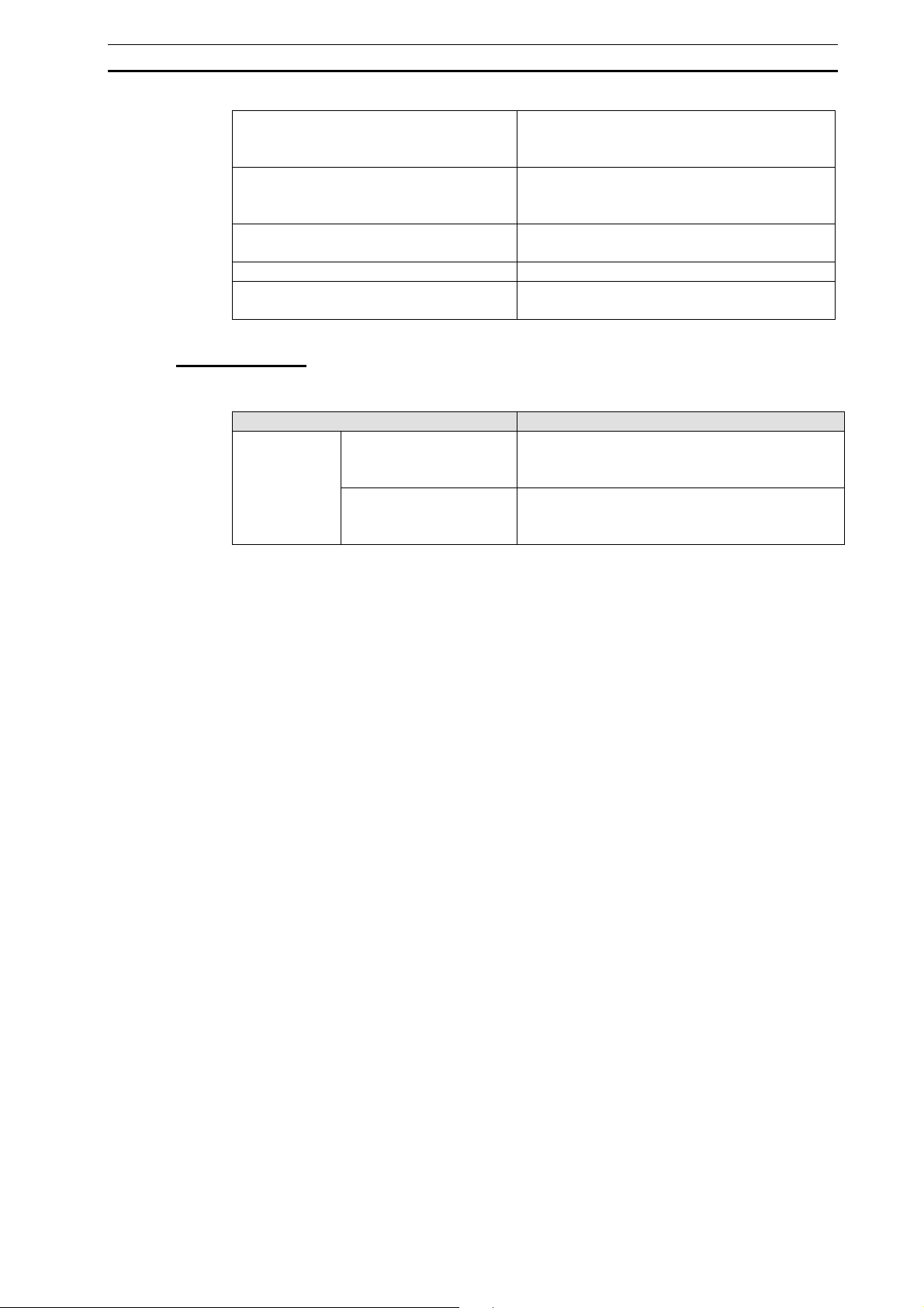
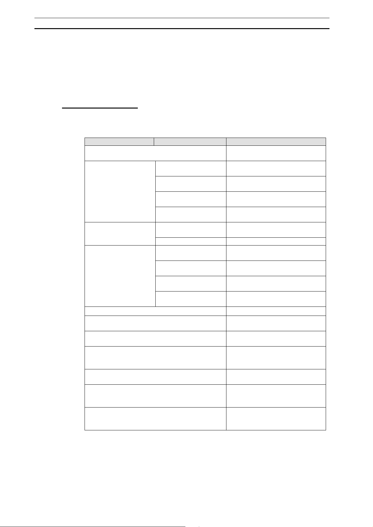
Defining Variables for the Unattended Paid Parking Lot
SFC program user variables must be defined for the external I/O devices.
External device I/O Variable name Variable type
Vehicle sensor Input carIn Boolean
Ticket sensor Input ticket Boolean
Gate open limit sensor Input gateopenLimit Boolean
Gate close limit sensor Input gatecloseLimit Boolean
Ticket dispenser Output ticketOut Boolean
Normal operation of gate motor Output gateopen Boolean
Reverse operation of gate
motor
Note: It is also possible to specify actual addresses, rather than variables.
Output gateClose Boolean
28
Page 45

SFC Programming Example Section 1-4
Example SFC Program for the Unattended Paid Parking Lot
The following example shows part of an SFC program for the ticket-issuing system of
an unattended paid parking lot, based on the defined action flow scenario and
variables. The action program is created using ladder logic.
Action Program (A_tiketOut): Starting/Stopping the Ticket Dispenser
P_On ticketout
Action Program (A_gateOpen): Starting/Stopping the Normal Rotation of the
Gate Motor
P_On gateOpen
Action Program (A_gateClose): Starting/Stopping the Reverse Rotation of the
Gate Motor
gateClosecarIn
Note: Leave each action program’s Reset Output at Final Scan setting at its default setting of ON
(reset).
29
Page 46
SFC Programming Example Section 1-4
1-4-2 Procedures for Using CX-Programmer
This section describes the programming flow and SFC chart editing procedure using,
as an example, the SFC program for the unattended paid parking lot ticketing system.
SFC Programming Flow
1 Select and right-click a Programs item in the project workspace, and select Insert
Program - SFC from the pop-up menu.
For details, refer to 3-1-2 Creating (Inserting) a New SFC Program.
2 Assigning the SFC program to a task
Select and right-click an SFC program item in the project workspace, and select
Properties from the pop-up menu.
On the General tab of the displayed Program Properties dialog, select a task from
the Task Type list.
For details, refer to 3-1-3 Assigning an SFC Program to a Task.
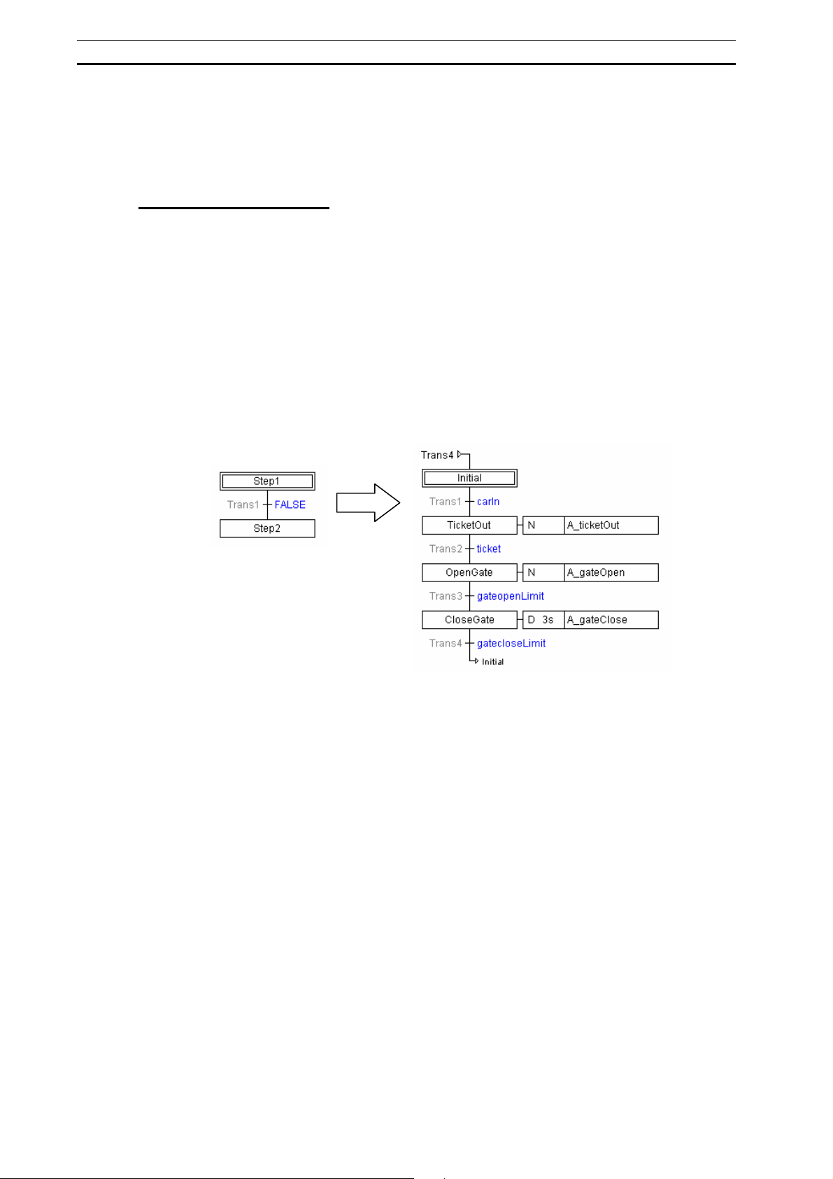
3 Editing SFC chart
When an SFC program is created, 3 types of SFC elements (initial step, transition,
and step) are registered in the SFC chart editor by default. Define the transition
conditions and actions by adding to these SFC elements.
4 Checking the program
Select and right-click an SFC program item in the project workspace, and select
Compile from the pop-up menu.
For details, refer to 3-4-1 SFC Program Check.
5 Transferring the SFC Program to the PLC
Select Transfer - To PLC from the PLC menu.
For details, refer to 4-2 Transferring Programs from Computer to PLC.
30
Page 47
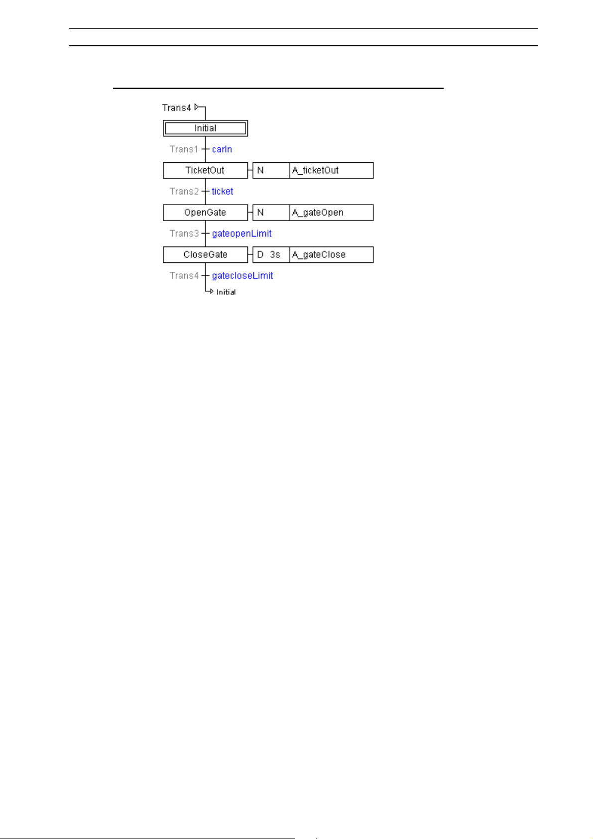
SFC Programming Example Section 1-4
Editing the SFC Chart for the Unattended Paid Parking Lot
1 Register the required user variables (carIn, ticket, ticketOut, gateopenLimit,
gatecloseLimit, gateOpen, and gateClose) in the local symbol table.
For details, refer to 1-4-1 Simple Example of an SFC Program.
In the project workspace, select the Symbols item for the SFC program item.
Right-click the symbol table, and select Insert Symbol.
Enter the variable name in the Name field of the New Symbol dialog, and click OK.
2 Create ladder action programs (A_ticketOut, A_gateOpen, A_gateClose) as
Actions folder in the project workspace.
Select and right-click the Actions folder for the SFC program items in the project
workspace, and select Insert Action - Ladder.
Right-click the inserted action program, select Properties, and enter the action
program name.
Right-click the inserted action program, select Open, and create the ladder action
program.
Note: Leave the action program’s Reset Output at Final Scan setting at its
default setting of ON (reset). Make the same setting for all of the following
action programs, too.
3 Input the name for Step 1.
Right-click Step 1, and select Edit Step Name.
Input Initial into Step 1.
4 Input the transition condition for Step 1.
Right-click the transition after Step 1, and select Edit Transition Condition.
Input carln as the transition condition.
5 Input the name for Step 2.
Right-click Step 2, and select Edit Step Name.
Input TicketOut into Step 2.
6 Add an action program to the action in Step 2.
Right-click Step 2, and select Add Action - Existing Action.
Double-click the right-hand side of the action block, and select A_ticketOut from
the combo box.
7 Input the transition condition for Step 2.
Right-click the transition after Step 2, and select Edit Transition Condition.
Input ticket as the transition condition.
8 Input the name for Step 3.
Right-click Step 3, and select Edit Step Name.
Input OpenGate into Step 3.
9 Add an action program to the action in Step 3.
Right-click Step 3, and select Add Action - Existing Action.
Double-click the right-hand side of the action block, and select A_gateOpen from
31
Page 48

SFC Programming Example Section 1-4
the combo box.
Double-click the left-hand side of the action block, and select D from the combo
box.
Double-click the timer value and input 3.
10 Input the transition condition for Step 3.
Right-click the transition after Step 3, and select Edit Transition Condition.
Input gateopenLimit as the transition condition.
11 Input the name for Step 4.
Right-click Step 4, and select Edit Step Name.
Input CloseGate into Step 4.
12 Add an action program to the action in Step 4.
Right-click Step 4, and select Add Action - Existing Action.
Double-click the right-hand side of the action block, and select A_gateClose from
the combo box.
13 Input the transition condition for Step 4.
Right-click the transition after Step 4, and select Edit Transition Condition.
Input gatecloseLimit as the transition condition.
14 Add a jump to Step 1.
Right-click the transition after Step 4, and select Connections - Add Connection.
On the Add Connection dialog, select Initial as the jump destination.
Check the Draw Connection as Jump checkbox and click OK.
32
Page 49

Precautions When Creating SFC Programs Section 1-5
1-5 Precautions When Creating SFC Programs
1-5-1 Holding or Resetting an Action’s Outputs
The action’s type determines whether the action’s outputs (see note) are held or reset
when the step goes from active to inactive status.
Note: In this section, the term “output” refers to the following.
• For a bit specification, it refers to the specified bit address value in memory.
• For a ladder program, it refers to the value written in memory by an instruction.
• For an ST program, it refers to the value written in memory by a statement.
Bit Specification
• The output is reset when a holding action qualifier (S) is not specified, but a qualifier
such as action qualifier (N) is specified.
• When a holding action qualifier (S) is specified, the output is held by the action
qualifier’s execution condition even if the step becomes inactive. In this case, the
output can be reset by using a resetting action qualifier (R) and adding a step, as
shown in the following chart.
S Ste p 1 Output
R Step 2 Output
Output: Boolean variable
Ladder Program
With the default setting, the outputs are reset.
If you want to retain the output status, deselect the ladder program’s Reset Output at
Final Scan Option (remove the check mark).
Note 1. When timer instructions are being used and outputs are set to be held (not reset), the
Timer Completion Flags will also be held, and the next time that the same action is
executed, it will start execution with the Timer Completion Flag ON. If you want to reset
the timer Completion Flags separately, include the action flag (see note 2) in the timer
instruction’s input condition by ANDing the flag as a NO condition to reset the timer.
2. The action flag is ON when the step is active, and OFF when the step is inactive.
The flag is written as Action_Name.Q. For details on action flags, refer to the explanation
of Flags Used to Monitor a Step’s Active Status in 2-3 Elements of SFC.
ST Program
With the default setting, the outputs are held.
If you want to reset the outputs, reset the outputs by including an “Action flag = FALSE”
condition (see note) in a statement such as an IF statement.
Note: The action flag is ON when the step is active, and OFF when the step is inactive. The flag
is written as Action_Name.Q. For details on action flags, refer to the explanation of Flags
Used to Monitor a Step’s Active Status in 2-3 Elements of SFC.
33
Page 50

Precautions When Creating SFC Programs Section 1-5
A
A
A
A
A
A
Example:
N Step 1 Action1
Action1
When step 1 has become inactive, action flag Action1.Q goes OFF, the action flag
(Action1.Q) becomes FALSE, and the output goes OFF.
1-5-2 Action Program Precautions
Action Program Execution Sequence
The order of execution for the actions in multiple steps that become active
simultaneously within the same SFC execution cycle is as follows:
1. Bits and Boolean variables
2. Action programs
If multiple action programs become active, they are each executed once each
cycle from top down according to their position in the action program tree in the
workspace.
Example 1
The execution order for multiple action programs registered in a single step is not
according to the order of the action programs next to the step, but rather in the order
the action programs are arranged in the workspace.
Note: If more than one bit or Boolean variable is registered in an action, they are executed in
the order that they are registered in the action block.
ction execution order
First bits CIO 10.01 (1) and CIO 10.02 (2) are
executed (i.e., turned ON), and then the action
ction program
execution order
programs are executed in the following order:
ction 2 (3), Action 1 (4), and Action 3 (5).
(5)
(1)
(3)
(2)
(4)
ction program
Bit or Boolean variable
ction program
Bit or Boolean variable
ction program
Type of action
Example 2
The execution order for actions in steps that simultaneously become active (e.g., steps
3 and 4) is not by step, but rather bits and Boolean variables are executed first and
then action programs.
Note: If more than one bit or Boolean variable is registered in an action, they are executed in
the order that they are registered in the action block.
34
Page 51
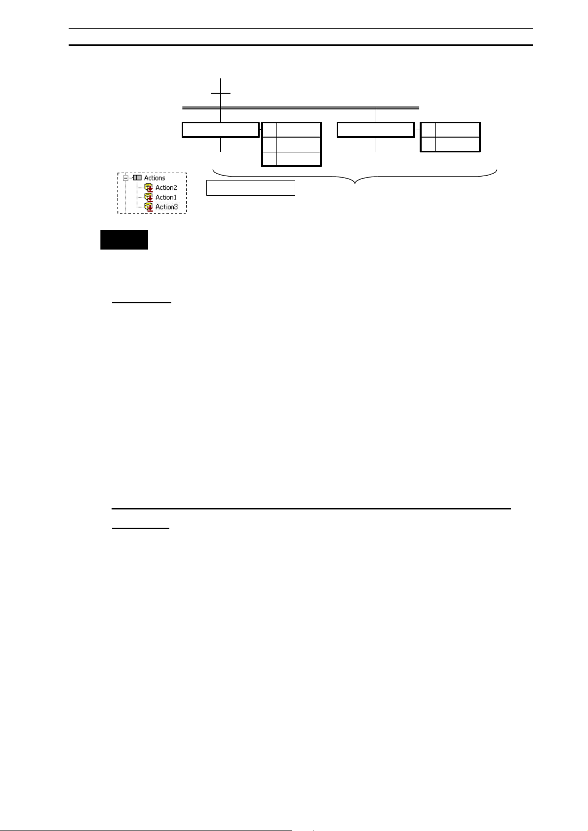
Precautions When Creating SFC Programs Section 1-5
(3)
A
(Action program tree in
workspace)
Note
Refer to 2-2 Basic SFC Execution Cycle for information on the basic SFC execution
cycle, including the order of execution for action programs. Refer to
for information on the execution of action blocks.
Final Scan
Final scan function is an action program execution method defined in the IEC 61131-3
standard. The CX-Programmer conforms to this IEC standard, and is equipped with the
final scan function.
The final scan function executes the action program just one more time after the
previously executed step becomes inactive, when programming switches to the next
step. This final scan function can be used to reset the outputs of the actions that were
executed.
Disabling the Final Scan Operation
The final scan function can be enabled and disabled with the following method. Select
Tools - Options from the menu, click the SFC Tab, select the Use Extended SFC
Settings
SFC program’s properties.
Option selected: Final scan execution is enabled for that entire SFC program.
Option not selected: Final scan execution is disabled for that entire SFC program.
FALSETrans2
Step3 Step4
ction execution order
First bits CIO 10.01 (1) and CIO 10.02 (2) are executed (i.e., turned ON), and then
the action programs are executed in the following order: Action 2 (3), Action 1 (4),
and Action 3 (5).
N 10.01
N Action2
N Action3
--(1)
--
--(5)
N 10.02
N Action1
--(2)
--(4)
2-3-3 Action Blocks
Option, and select the Apply Final Scan Logic Option in the General Tab of the
Programming Precautions When Passing Execution Results through a
Transition
When the final scan is enabled, the step action will be executed once in the next cycle
after the step changes from active to inactive status. Always use the following method
to write the action programs in the step before the transition to prevent the final scan
from affecting the results when calculation results, such as counter values, from an
action in the step before the transition are being evaluated in the step after the
transition.
Ladder Programming
Observe the following precautions if the Reset Output at Final Scan Option is
deselected (check mark removed) in the ladder program’s properties.
When a program section has a calculation that you do not want executed when the
step become inactive, always add the action flag as a NO condition for the calculation
by ANDing the flag in the execution condition for the calculation.
For details on action flags, refer to the explanation of
Active Status
in 2-3 Elements of SFC.
Flags Used to Monitor a Step’s
35
Page 52

Precautions When Creating SFC Programs Section 1-5
Example 1
0.00
++(590)
D0
0.00
Action.Q
Add action flag.
++(590)
D0
With processing such as the increment processing shown above, add the action flag by
ANDing the flag as a NO execution condition. Even if the final scan is executed, the
value of D0 will not be incremented in the final scan.
Example 2
0.00
TIM
0010
___
#10
Action.Q
JMP0(515)
Add action flag.
0.00
TIM
0010
___
#10
When you do not want a timer/counter PV refreshed after the step becomes inactive in
timer/counter instruction processing like the processing in the chart shown above, add
the action flag by ANDing the flag as a NO execution condition to a JUMP (JMP0)
instruction, and enclose the timer/counter instruction between JMP0 and JME0. Even if
the final scan is executed, the PV will not be refreshed additionally.
ST Program
Include an “Action flag = FALSE” condition with an AND condition in a statement such
as an IF statement, and execute the processing.
1-5-3 Precautions for Transition Programs
A bit output or timer/counter instruction used in a transition program will not be reset
when moving to the next step, i.e., operation of the bit output or timer/counter
instruction will continue.
36
JME0(516)
Page 53

Precautions When Creating SFC Programs Section 1-5
1-5-4 Ladder Language Instructions That Cannot Be Used in
Action Programs and Transition Programs
The following instructions cannot be used for action programs and transition programs.
Unsupported instructions
Block programming instructions (All instructions, including BPRG and BEND)
Subroutine instructions (SBS, GSBS, RET, MCRO, SBN, GSBN, and GRET)
Jump instructions (JMP, CJP, CJPN, and JME)
Step ladder instructions (STEP and SNXT)
I/O refresh instruction (IORF)
TMHH and TMHHX instructions
Special instructions (FRMCV and TOCV)
Record position manipulation instructions (PUSH, FIFO, LIFO, SETR, and
GETR)
Failure point detection Instruction (FPD)
Index register setting instruction (MOVRW)
1-5-5 Task Allocation
SFC programs are assigned to cyclic tasks to use them. (See note.) Refer to 3-1-3
Allocating an SFC Program to a Task
Note: Do not use SFC programs in interrupt tasks. They will not execute normally.
Allocating Extra Tasks
The CS/CJ-series PLCs provide 32 cyclic tasks (128 cyclic tasks only for CJ2-series
PLCs). In addition to this, up to 256 extra tasks can be used. (Extra tasks are interrupt
tasks that are executed each cycle as cyclic tasks.) (See note 1.)
The CX-Programmer can be used to create SFC programs, ladder diagrams, or ST
programs in either cyclic tasks or extra tasks. Extra tasks containing SFC programs are
started and stopped using the SFCON and SFCOFF instructions from other tasks.
(See note 2.) The following numbers are used in the SFCON and SFCOFF instructions
to specify the task numbers. Refer to
Specifications
for specifying methods.
Task Number
Extra task 0 (interrupt task 0) 8000
Extra task 1 (power OFF task) 8001
Extra task 2 (scheduled interrupt task 1) 8002
Extra task 3 (scheduled interrupt task 2) 8003
Extra tasks 4 to 99 (interrupt tasks 4 to 99) 8004 to 8099
Extra tasks 100 to 131 (I/O interrupt tasks) 8100 to 8131
Extra tasks 132 to 255 (interrupt tasks 132 to 255) 8132 to 8255
Note 1. When using extra tasks, be sure to refer to the CJ2H Programmable Controllers Software
User’s Manual (Cat. No. W473) and the CS/CJ/NSJ Programming Manual (Cat. No.
W394) and confirm application methods. If the conditions to execute extra tasks as
interrupt tasks are met, the task will not execute normally.
2.Do not use the TKON and TKOFF instructions to stop and start tasks with SFC programs.
The instructions will not function normally.
for information on allocating tasks.
Appendix B SFC Task Control Instruction
37
Page 54

Precautions When Creating SFC Programs Section 1-5
1-5-6 Memory Allocation
In CX-Programmer, the system allocates memory automatically to steps, transitions,
and actions. With the factory default setting, the “FB Non Retain” memory area (H512
and later) of the function block will be allocated.
This memory area may be insufficient, however, for larger SFC programs. In this case,
use the “SFC bit” and “SFC word” memory areas for SFC.
When using the “SFC bit” and “SFC word” memory areas for SFC, uncheck the Share
SFC with FB Memory
checkbox.
Default Value Memory Area
First Address End Address Size
FB Non Retain H512 H1407 896 CIO, WR, HR, DM,
FB Retain H1408 H1535 128 HR, DM, EM
FB Timer T3072 T4095 1024 TIM
FB Counter C3072 C4095 1024 CNT
SFC Bit N/A N/A N/A -
SFC Word N/A N/A N/A -
Note: DM or EM can be used for the "FB Non Retain" memory area. Uncheck the Share SFC
with FB Memory checkbox, since neither DM nor EM can be used as memory areas for
SFC.
Setting Procedure
1 Select Memory Allocation – Function Block/SFC Memory – Function
Block/SFC Memory Allocation
from the PLC menu.
The Function Block/SFC Memory Allocation Dialog Box will be displayed.
2 Uncheck the Share SFC with FB Memory checkbox.
Allocable
Area
EM
38
3 Select SFC Bit or SFC Word.
4 Click the Edit Button in the Function Block/SFC Memory Allocation Dialog Box.
The Edit Function Block/SFC Memory Range Dialog Box will be displayed.
5 Select Memory Area and input First Address and Size.
6 Click the OK Button in the Edit Function Block/SFC Memory Range Dialog Box.
7 Click the OK Button in the Function Block/SFC Memory Allocation Dialog Box.
Note: Set the memory areas for both "SFC bit” and “SFC word”.
Page 55

Precautions When Creating SFC Programs Section 1-5
1-5-7 Subchart Online Editing Function Restrictions
Subcharts cannot be edited during online editing.
39
Page 56

Precautions When Creating SFC Programs Section 1-5
40
Page 57

SECTION 2
SFC Fundamentals
2-1 SFC Basic Operation.................................................................................................42
2-2 Basic SFC Execution Cycle.......................................................................................43
2-3 Elements of SFC........................................................................................................44
2-3-1 Steps................................................................................................................................44
2-3-2 Transitions.......................................................................................................................50
2-3-3 Action Blocks..................................................................................................................52
2-3-4 Divergences.....................................................................................................................59
2-3-5 Convergences..................................................................................................................5 9
2-3-6 Simultaneous Sequence Divergences..............................................................................60
2-3-7 Simultaneous Sequence Convergences...........................................................................60
2-3-8 Connections.....................................................................................................................61
2-3-9 Automatic Registration of SFC Elements as Local Variables.........................................62
41
Page 58

SFC Basic Operation Section 2-1
A
A
A
2-1 SFC Basic Operation
This section describes the behavior of an SFC program using a basic step progression
control.
Step Progression Control
Step progression control is a method of program control in which the execution of each
step, consisting of an entire process, is sequential or time-dependant.
SFC is a graphical programming language developed to allow step progression control
to be easily implemented. Step Ladder has been widely used as a language for
describing step progression control, but SFC has visual properties superior to
traditional Step Ladder.
Consider the following example: “Execute Process 1 until Condition A is met, then stop
Process 1 and execute Process 2”. The following shows the behavior of an SFC
program using basic step progression control (Process 1 is executed and, if condition A
is met, process 2 is executed) as an example.
Step 1
Step 2
Trans1
Action 1
Action 2
ssign Process 1 to Action 1.
ssign Process 2 to Action 2.
ssign Condition A, the transition condition between steps, to
Trans 1.
A step is either active or inactive.
An active step executes the actions defined in that step.
If the condition for the step to transfer to the next step is met, then the immediately
preceding step becomes inactive and the immediately succeeding step becomes
active.
The following illustrates that the transition condition, "Trans1" is met and that the active
status has transferred from step 1 to step 2.
The step showing "z" is the active step.
Step 1
Step 2
z
Trans1
Action 1
Action 2
Conditions Met for
Trans 1
Step 1
Trans1
Step 2
z
Action 1
Action 2
All the actions within an active step are executed for at least one cycle, even if the
condition for the step to transfer to the next step has been met (Note, however, that the
execution of some actions may be prevented by AQs).
42
Page 59

Basic SFC Execution Cycle Section 2-2
2-2 Basic SFC Execution Cycle
The following processing is performed in the SFC execution cycle as 1 unit for all active
steps. No processing is performed for inactive steps.
Action execution judgment
Action execution
Transition evaluation
Cycle
Step transition processing
Subchart processing
z Action execution
judgment
z Action execution
z Transition
evaluation
z Step transition
processing
z Subchart
processing
I/O refreshing
The results of the previous cycle’s step transition processing is received, and the AQ
(action qualifier) is read to determine whether or not the all of actions will be executed.
When a Boolean bit is specified in the action, the action is executed based on the result of
the action execution judgment. When multiple Boolean bits are specified in a single step,
they are executed in the order (from top to bottom) that they appear in the action block.
If active status has changed since the previous cycle, final scan processing (see note) is
performed for any action programs in steps that have changed to inactive status.
Note: Refer to 1-5-2 Action Program Precautions for information on the final scan
operation.
When a step is active, the action programs written in the step are executed in the following
order, including actions in subcharts, based on the result of the action execution judgment.
• First, all actions for which Boolean variables are specified are executed according to
the action execution judgment. Then action programs are executed. For information on
the execution order of action programs, refer to 1-5-2 Action Program Precautions.
• When the same action program is specified in two or more steps that are active at the
same time, that action program will be executed just once in a cycle.
The transition conditions of active steps are evaluated. The transition program connected
after the active step is executed at this time.
The current step is switched to inactive status and the next step is switched to active
status if the transition evaluation determined to move to the next step.
Note 1: The status is switched even if the next step is active (see note 2). If you do not
want the status to switch, add a transition condition that checks whether or not
the next step is active.
Note 2: SFC operation is different in the CV-series PLCs. In the CV-series PLCs, the
status is not switched if the next step is active.
The subchart is executed if the subchart step is active. Subcharts are processed in the
following order:
1. Subchart initialization
2. Transition evaluations inside the subchart
3. Step transition processing inside the subchart
4. Processing to return from the subchart
Note: Actions inside a subchart are executed at the same timing as previously
described in Action Execution. If more than one subchart is active at the same
time, the subcharts are executed from top down in the order the subcharts are
arranged in the workspace.
43
Page 60
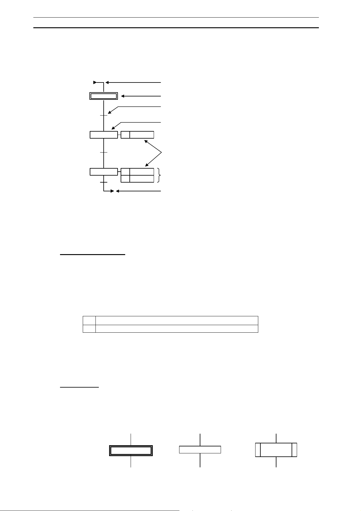
Elements of SFC Section 2-3
A
2-3 Elements of SFC
This section explains the element of SFC.
JUMP ENTRY: Jump Destination
Initial step: The first step to be made active.
2-3-1 Steps
A step is an element of an SFC program and represents a single process within an
entire process.
Operation of Steps
A step is either active or inactive.
An active step executes the actions defined in that step, while an inactive step does not
execute any actions until it becomes active.
The step status transfers when the transition condition is met, but the transfer actually
depends the status of the step before the transition as well as the transition condition.
The status of steps transfers when all of the following conditions are met.
z Step Transfer Condition
1 All transition conditions have been met.
2 All steps before the transition point are in the active status.
Note: The step transfers even if the connecting step after the transition is active.
Some steps do not have an action to execute. These steps will remain in the waiting
status, with no processing to perform until the transition conditions are met.
Steps, which do not have an action to execute, are referred to as “dummy steps”.
Transition
Step
ction
Can be multiple (Number unlimited).
Jump: Jumps to the destination step
Supported
Boolean variable (Bit)
Boolean address (Bit)
ST expression
Program (Ladder or ST)
Supported
Boolean variable (Bit)
Boolean address (Bit)
Program (Ladder or ST)
Step Types
There are following types of steps:
• Initial step
• Normal step
• Subchart step
Initial
Step
Step 1
Normal
Step
Step 1
Subchart
Step
Step 1
Subchart 1
44
Page 61
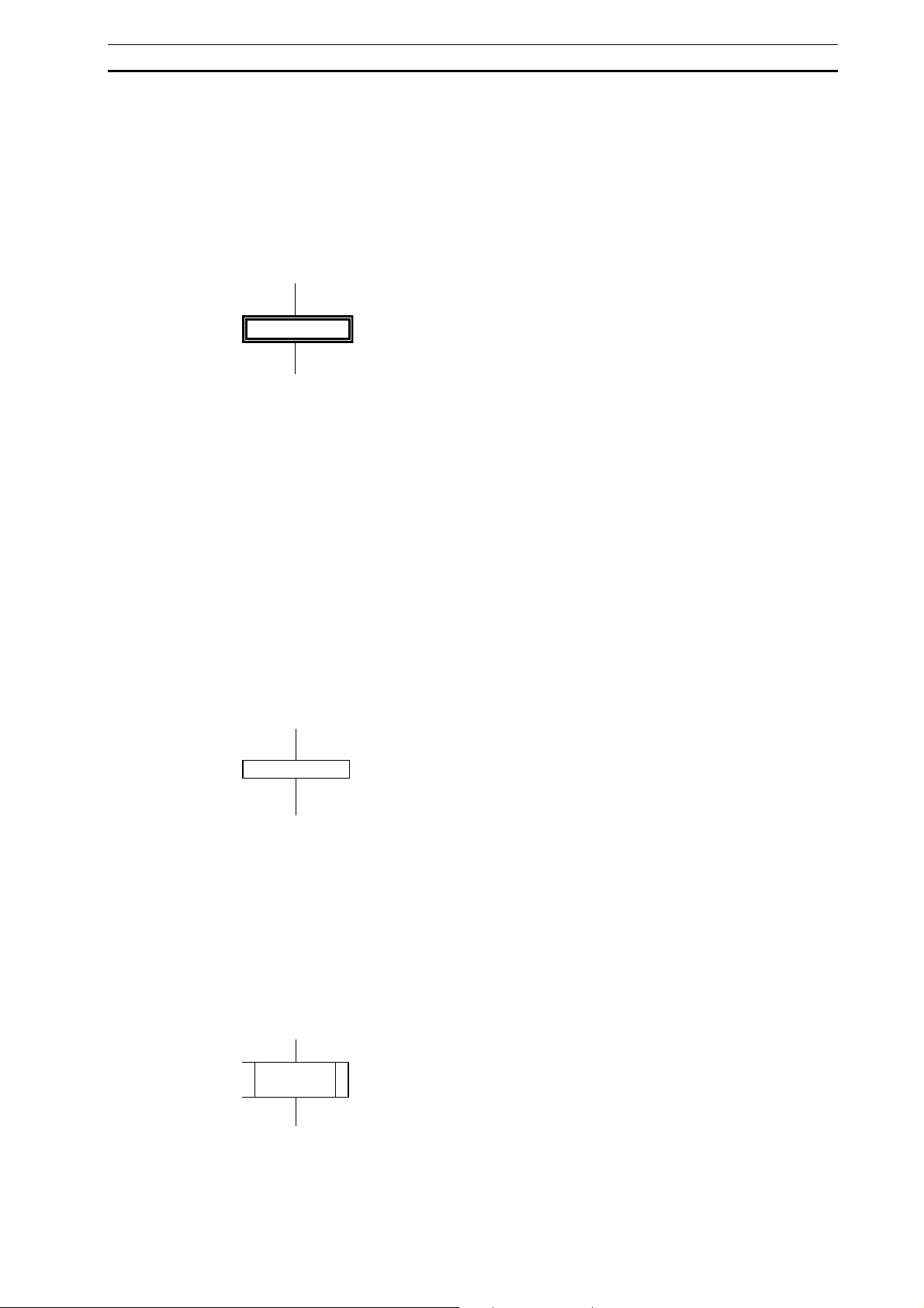
Elements of SFC Section 2-3
Initial Step
An initial step is the step that unconditionally becomes active upon program execution
start. All other steps are inactive at this moment.
It is also the first step to be executed in the SFC chart.
When the initial step becomes active, the actions defined in the initial step are
executed.
The initial step is represented as shown below.
Step 1
• Only one initial step can be created within an SFC chart.
• The initial step does not necessarily need to be positioned at the head of the
program.
• An initial step can hold one or many action blocks.
• When the initial step becomes active, action blocks assigned to the step are
executed.
If the power supply is turned OFF during SFC program execution. The program will be
executed from the initial step when the power supply is turned back ON. To perform
initialization when continuing operation or to select the steps with the step control
instructions to continue step operation, include status control programming in the initial
step.
Normal Step
A normal step is the step that becomes active if the transition condition is met.
When the step becomes active, the actions defined in the normal step are executed.
The normal step is represented as shown below.
Step 1
• There is no limit on the number of normal steps used within an SFC chart.
• A normal step can hold one or many action blocks.
• When a normal step becomes active, action blocks assigned to the step are
executed.
Subchart Step
A subchart step is the step that calls up the subordinate SFC chart (subchart) from an
SFC chart.
The subchart step is represented as shown below.
Step 1
Subchart 1
A subchart is the macro expansion of an SFC step into a group of SFC programs,
similar to the subroutine of a conventional programming language.
45
Page 62

Elements of SFC Section 2-3
Subchart
Step
Step 10
Step 11
Subchart 1
Step 12
Step 1
Trans1
Step 2
Trans2
Step 3
Subchart
Entry Terminal
Entry Step
FALSE
FALSE
Return Step
Subchart
Return Terminal
Subchart
A subchart is called up by a subchart step. Its execution begins at the subchart entry
terminal, and returns to the main process flow at the subchart return terminal.
• There is no limit on the number of subchart steps used within an SFC chart.
• If the transition conditions (for the downside transition) are met while a subchart step
is active, the active status is not transferred to the next subchart step until the SFC
within the subchart reaches its return step.
• The processing of a subchart always begins at the subchart entry terminal () and
ends at the subchart return terminal (
).
• When the return step becomes active, it will remain active until the active status is
transferred for the parent subchart.
• Each subchart requires one entry step and one or more return steps. There is no limit
on the number of return steps within a subchart.
• A subchart can call up another subchart.
There is no limit on the subchart layers.
• When the return step becomes active and the subchart is terminated, all other active
steps within the subchart are simultaneously terminated.
• A subchart step does not hold any action.
• A single subchart can be called up by multiple subchart steps. When two subchart
steps attempt to call up the same subchart, however, the latter caller must wait until
subchart execution is completed for the former caller.
46
Page 63

Elements of SFC Section 2-3
A
Step Control Instructions
Step control instructions (SA, SE, TSR, TSW) can be used to control SFC steps.
SA: Activate step (Switches a step to the activate status)
SE: Deactivate step (Switches a step to the inactivate status)
TSR: Read step timer value instruction (Reads the present value of the step timer)
TSW: Set step timer value instruction (Updates the present value of the step timer)
In each of the instructions, the step flag is specified as follows:
• For within the same task [step name].X
For within another task
In each of the instructions, the step timer is specified as follows:
[program name].[step name].X
• For a step within the same task [step name].T
• For a step within another task [program name].[step name].T
• For a subchart step within the same task [subchart name].[step name].T
• For a subchart step within another task [program name].[subchart name].[step
name].T
For details on step flags, refer to the following description under Flags Used to Monitor
a Step’s Active Status.
Step activation/deactivation instructions can be used for the following
purposes.
Controlling a Step in an SFC Program from an External Ladder Program
Ladder Program
SA
SE
Deactivate
SFC Program
ctivate
47
Page 64

Elements of SFC Section 2-3
A
A
Controlling a Step in an SFC Program from an Action Ladder Program within
the Same SFC Program
SFC Program
SA
ctivate
Controlling an SFC Step from an Action Ladder Program within Another SFC
Program
SFC Program
SFC Program
ctivate
SA
Note: If the SA step control instruction is used to activate another step in the same
SFC program from an action ladder program in the SFC program, the activated
step’s action will be executed in the next cycle.
If the SA step control instruction is used to activate a step in a different SFC program
from an action ladder program in the SFC program, the activated step’s action will be
executed in the current or in the next cycle, depending on the order of the SFC
program execution task numbers.
• If the SFC program containing the step activated with the SA step control
instruction has already been executed, the activated step will be executed in the
next cycle.
• If the SFC program containing the step activated with the SA step control
instruction has not yet been executed, the activated step will be executed in the
same cycle.
Step timer value read/set instructions can be used in the same way as step
activation/deactivation instructions.
• A step can have a step timer to maintain the time, which has elapsed since the step
became active. For each step, the time unit on the step timer can be set to either
of the following:
48
Page 65

Elements of SFC Section 2-3
• 100 milliseconds
• 1 second
• The first operand time range for a step timer value instruction reading varies,
according to the time unit of the specified step timer, as follows.
• 100 milliseconds 0 to 6553.5 seconds
• 1 second 0 to 65535 seconds
• Actions with the action qualifier D, DS, or L are executed in synchronization with
the step timer. Caution should therefore be exercised when making changes to the
step timer of a step, which has those action qualifiers in its actions.
• When the step becomes inactive, the step timer is stopped, and the elapsed time
data is saved. The step timer is reset when the step becomes active again.
• When the step timer value reaches the upper limit, the timer will stop and maintain
the maximum value.
For detailed specifications of step control instructions, refer to Appendix A –
Specifications for Step Control Instructions.
Precautions on Subcharts
Executing the SA Step Control Instruction for a Subchart Step
When the SA step control instruction is executed for a subchart step, that subchart step
will become active, and the subchart will operate from the entry step.
Executing the SE Step Control Instruction for a Subchart Step
When the SE step control instruction is executed for a subchart step, that subchart step
will become inactive, and the subchart’s operation will stop. (Active steps in the
subchart will become inactive.)
Using the SA and SE Step Control Instructions in a Subchart Step
The SA and SE Step Control Instructions cannot be used for a step in the same
subchart.
Note: SFC operation is different in the CV-series PLCs. In the CV-series PLCs, subchart steps
can be used in instruction operands.
Operation When Multiple Subchart Steps Calling the Same Subchart Are
Active
• When a given subchart step is active, another subchart step calling the same
subchart can become active by a status transition or execution of the SA instruction
(see note). In this case, the subchart’s current execution status will not change.
Execution of the subchart for any other subchart steps will standby until the subchart
step that first called the subchart becomes inactive.
• If the subchart step for which the subchart is currently being executed changes to
inactive status or the subchart step is deactivated with the SE instruction, the
subchart will be executed again from the entry step for any other subchart step that
was in standby status.
• If a subchart is currently being executed for one subchart step and another subchart
step calling the same subchart changes to inactive status or the subchart is
deactivated with the SE instruction, the subchart execution will continue as long as
the subchart step for which the subchart is currently being executed is still active.
Note: SFC operation is different in the CV-series PLCs.
In the CV-series PLCs, if a given subchart step is active, another subchart step calling
the same subchart cannot become active by a status transition or execution of a step
control instruction. In this case, execution of the previous step continues, and the step
goes into standby status.
• When multiple subchart steps are in standby status, the subchart that is executed
next is determined by the order in which the subchart steps are registered.
The execution order can be confirmed in the Action Used List Dialog Box. Refer to
Checking Action Usage under 2-3-3 Action Blocks.
49
Page 66

Elements of SFC Section 2-3
E
Flags Used to Monitor a Step’s Active Status
Step Flags
These flags indicate the steps active/inactive status.
The flags are expressed as Step_name.X, and each flag will be ON when the
corresponding step is active or OFF when the corresponding step is inactive.
Step Timers
These timers indicate how long each step has been active.
The timers are expressed as StepName.T, and the timer’s units can be set to 100 ms
or 1 s units for each step.
Procedures:
Adding a Step
Right-click a transition, and select Add Step.
Defining the Initial Step
To convert a normal step to an initial step, right-click the normal step, and select Step
Type - Initial.
Adding a Subchart Step
Right-click a transition, and select Add Subchart Step - New Subchart.
Defining a Subchart
Right-click a Subcharts folder in the project workspace, and select Insert SFC
Subchart.
Administering a Step Control Instruction
Input the instruction as a regular ladder instruction, and specify the target step flag.
2-3-2 Transitions
A transition represents the condition in which the active status transfers from the step
before the transition to the step after it. One transition must be set between steps.
The transition is represented as shown below.
Trans1
FAL S
Operation of Transitions
When the transition condition is met, the step before the transition becomes inactive
and the step after it becomes active.
In this way, the transition controls the program flow from step to step.
• When representing transition conditions with transition programs, turning a transition
program name ON will turn the represented transition condition ON.
Transition Conditions
Transition conditions are to be defined on the right-hand side of the figure.
When a transition is added to the SFC editor, its default condition is the ST expression
“FALSE”.
The condition equation for a transition can be set to any one of the following:
• Bit (Boolean variable or actual address)
• ST expression
• Transition program name
50
Page 67

Elements of SFC Section 2-3
A
Boolean Action (Bit)
Boolean Variable
A transition condition can be defined using a Boolean variable name.
Example: In the case of “bFlag”, the condition is met when “bFlag” is ON.
Actual Address (Bit)
A transition’s condition can be defined using an actual address (bit).
ST Expression
A transition condition can be defined using an ST expression.
Formats for ST-programmed condition equations are listed below:
Formats for Boolean Variables in Defining Transitions with ST Expressions
Operator
Name
Parenthesis () (a & b) OR c Condition met if both “a” and “b” are ON, or if
Complement NOT NOT bFlag Condition met if bFlag is OFF
AND AND, & a & b Condition met if both “a” and “b” are ON
Exclusive OR XOR a XOR b Condition met if “a” differs from “b”
OR OR a OR b Condition met if “a” or “b” is ON
Equality = a = b Condition met if “a” and “b” are the same
Operator Example Details
“c” is ON
Formats for INT, DINT, LINT, UINT, UDINT, ULINT, CHANNEL, REAL, LREAL, WORD,
DWORD, LWORD, UINT_BCD, UDINT_BCD, and ULINT_BCD Variables in Defining
Transitions with ST Expressions
Operator
Name
Parenthesis () (nValue = 10) & a Condition met if nValue is 10 and “a” is ON
Operator Example Details
Comparison <, >, <=, >= nValue >= 10 Condition met if nValue is 10 or greater
Equality = nValue = 10 Condition met if nValue is 10
Inequality <> nValue <> 10 Condition met if nValue is not 10
Transition Program
Program names may be used as transition conditions.
A transition program can be coded using either Ladder or ST as the language.
In CX-Programmer, a transition condition is met when the Boolean variable with the
same name as the transition program is switched to “ON”.
Example 1: “b” bit for “a”
PRG
ny name
Transition Program Name
PRGa
Condition met if “a” is OFF
51
Page 68

Elements of SFC Section 2-3
A
A
Example 2: OR bits for “a” and “b”
TRANS
ny name
Transition Program Name
TRANSa
b
Condition met if “a” or “b” is ON
When a transition program is used as a transition condition, specify a transition
program name for the transition condition. If a conditional equation is specified with a
different Boolean variable name, than that of transition program name for the transition
condition, the program will not run properly.
b OR TRANS
nother Boolean
Variable name
Transition Program Name
TRANSa
The condition of a Boolean output that was used inside a transition program is also
retained after moving to the next step.
Ladder Program
Some instructions are not supported when defining a transition program in ladder logic.
For details, refer to 1-5-4 Ladder Language Instructions That Can Not Be Used in
Action Programs and Transition Programs.
Do not use timer instructions in a transition program. A timer that has timed out cannot
be reset in a transition program.
An END instruction is not required at the end of a ladder transition program.
ST Program
For specifications on the ST language used when defining transition programs in ST,
refer to Part 2: Structured Text (ST) in the CX-Programmer Operation Manual Function
Blocks/Structured Text (Cat. No. W447).
Procedures:
Adding a Transition
Right-click a step, and select Add Transition.
2-3-3 Action Blocks
An action block is used to program the processes for a step.
A single step can register multiple action blocks.
An action within an action block can have the following information registered.
• Action Qualifier (AQ)
• Action name
• Indicator Variable
An Action block is represented as shown below. In the following figure, action qualifier
(AQ), action name, and indicator variable are illustrated, from left to right.
52
Page 69

Elements of SFC Section 2-3
AQ A
Step 2
N Action 1
N bFlag
ction Name
• An action block is inserted into a single step.
• There is no limit on the number of actions registered with an action block.
Administering Action Blocks
When a step becomes active, all actions in its action block are executed according to
the conditions set by the action qualifier.
While a step is in the active status, each action in its action block is executed once
each cycle. During a cycle, action blocks are executed in sequence, from top to bottom,
when Boolean bits are specified. With action programs, the programs are executed in
sequence after execution of the Boolean bit actions, and the sequence is from top to
bottom, in the order that they appear in the project workspace.
Action Qualifier (AQ)
AQ defines the execution timing for each action.
It can determine how the actions should be executed when the step becomes active.
Only one AQ can be specified for each action.
The action’s type determines whether the outputs are held or reset when the step goes
from active to inactive status. When necessary, change the initial settings or add reset
processing to the program.
• When a bit is specified, the output is reset when a holding action qualifier (S) is
not specified. The output status is held if a holding action qualifier is specified.
• With ladder programs, the outputs are reset by default. The default setting can
be changed to hold the output’s status.
• With ST programs, the status of the outputs in the program is held by default.
When necessary, write reset processing in the program and use the Action
Flag (a flag that goes ON when the corresponding step in an ST program
becomes inactive) to control the reset processing.
Note: For details, refer to 1-5-1 Holding or Resetting an Action’s Outputs.
Types of Action Qualifiers (AQs)
There are 11 AQ types, as follows. D, DS, L, SD, and SL have a time element.
For functions and for time element availability of the 11 AQ types, refer to the following
table.
AQ List
AQ
Symbol
D Delay The action is executed after the user-specified time has
DS Delay SET Carries out the same operation as "SD". In contrast to “SD”,
L Limit When the step becomes active, the action is executed until
N Normal
Name Function Timer Set
passed, since step activation. If the step becomes inactive
before the user-specified time expires, the action will not be
executed.
the action will not be performed if the step becomes inactive
before the user-specified delay time expires. To cancel the
execution, use the “R” AQ.
the user-specified time expires. Should the step become
inactive, execution of the action will be terminated.
The action is executed for as long as the step is active.
(Default)
Indicator Variable
Indicator Variable
Required?
Yes
Yes
Yes
53
Page 70

Elements of SFC Section 2-3
P Pulse If the final scan function is enabled, the action is executed for
two cycles when the step becomes active.
If the final scan function is disabled, the action is executed for
only one cycle when the step becomes active.
P1 Rising
Pulse
P0 Falling
Pulse
R Reset When a step becomes active, and its action is being executed
S Set The action is executed when the step becomes active, and
SD Set
Delay
SL Set
Limit
The action is executed once, each time the step becomes
active.
The action is executed once, each time the step becomes
inactive.
by the "S", "SL", "SD", or "DS" AQ, the specified action is
stopped and reset. If the action is being executed, but not by
the "S", "SL", "SD", or "DS" AQ, then the action is only reset
(not stopped). The reset operation sets the following:
OUT/OUT NOT instruction: “OFF”; TIM/TIMH instruction:
“Reset”; Other Timer/Counter/Shift registers: “Hold”.
continues to be executed, even after the step becomes
inactive. To cancel the execution, use the “R” AQ.
The action is executed after the user-specified time has
passed, since step activation, and continues to be executed,
even after the step becomes inactive. To cancel the
execution, use the “R” AQ.
The action is executed when the step becomes active, and
until the user-specified time expires. In contrast to “L”, the
action continues to be executed even after the step becomes
inactive. To cancel the execution, use the “R” AQ.
Yes
Yes
The timer set value is a setting used by AQs, which require a time element.
Timer set value is required by the following AQs:
D, DS, L, SD, SL
D, DS, and L control the timing of action execution, using the step timer. The time unit
on the timer is the same as that on the step timer for the step to which the action block
is allocated.
SD and SL control the time using a different timer than the step timer, since they
operate independently of step status.
54
Page 71

Elements of SFC Section 2-3
A
A
s
Action Execution Timing for Action Qualifiers (AQs)
Step Status
Q
N
P
P1
P0
L
D
Executed
Not Executed
*
Set Value
Set Value
ctive status
Inactive status
* Executed just twice when the
final scan function is
enabled.
Executed just once when the
final scan function is
disabled.
(When the action is a bit, it i
ON for just one cycle.)
S
Set Value
Set Value
SL
Set Value
SD
Set Value
DS
Set Value
Set Value
Actions
An action is executed when a step changes to the active status. Actions can be
specified as either of the following:
• Bit (Boolean variable or actual address)
• Action program name
When an action is defined as a Boolean variable (bit), the bit is turned ON when the
action is executed, and turned OFF when the action is stopped.
When an action is defined as an action program name, the action program is executed
when the action is executed, and stopped when the action is stopped.
Note: Multiple steps can run the same action program within a single execution of the SFC. Only
simultaneously activated steps are affected by single scan execution.
Boolean Variable or Actual Address (Bit)
An action block can be defined as a Boolean variable or actual address (bit). When the
step becomes active, the Boolean variable or actual address (bit) is turned ON
according to the AQ, and the bit is turned OFF if the action stops.
Set Value
R
Termination of execution
by the “R” AQ
55
Page 72

Elements of SFC Section 2-3
Action Program
If the action is executed, the specified action program is executed.
Note: The same action program can be specified in multiple steps of an SFC chart. When two or
more steps are active at the same time and have the same action program specified, that
action program is executed just once in a cycle.
An action program can be coded using either Ladder or ST as the language.
Ladder Program
An action block can be defined as a ladder program.
Some instructions are not supported when defining an action program in ladder logic.
For details, refer to 1-5-4 Ladder Language Instructions Can Not Be Used in Action
Programs and Transition Programs.
In ladder programs, the Reset Output at Final Scan Option can be selected in the
action’s properties to turn OFF the ladder program’s outputs when the step is inactive.
If function blocks are used in the ladder program, the status of outputs used in the
function blocks will be held.
Note: If the action qualifier is set to “N”, the ladder program may not be able to correctly detect
the step “rising” to the active status. For this reason, if a process is to be executed only
once, upon the activation of the step, the “P1” action qualifier should be used.
ST Program
An action block can be defined as an ST program.
For specifications on the ST language used when defining transition programs in ST,
refer to Part 2: Structured Text (ST) in the CX-Programmer Operation Manual Function
Blocks/Structured Text (Cat. No. W447).
Action Execution Order
Refer to 1-5-2 on Action Program Precautions for information on the order of execution
of actions within a step and the actions within multiple active steps.
Checking Action Usage
It is possible to display a list of all of the actions (Boolean bit specifications and action
programs) in a single SFC program.
Select Program – Action used list. The following dialog box will be displayed, so that
the use of the actions can be checked.
• Selecting the Main SFC • Selecting a Subchart
56
• Steps are displayed from the top in the order in which they are registered.
Multiple active subcharts are executed in the order in which they are registered,
i.e., from top down as they are displayed in the dialog box.
Page 73

Elements of SFC Section 2-3
• If an action is used in more than one step, it will be displayed in parentheses from
the second occurrence on to indicate that it is used more than once.
Flags Indicating the Execution Status of Actions
There are two kinds of flags that indicate an action’s execution status. Both kinds of
flags are changed by the step’s active/inactive status, and both can be used as bits in
ladder and ST programs.
Action Flag Q (Action_name.Q)
This flag is ON when the step is active, and goes OFF when the step is inactive.
This flag can be used as an input condition in a ladder or ST program to prevent
execution of a process when a step is deactivated. The flag can also be used as an
input condition in an ST program when resetting outputs.
Action Flag A (Action_name.A)
This flag is ON when the step is active, and goes OFF when execution of the final scan
is completed after the step is deactivated.
Use the Action Flag A as a set with the Action Flag Q when special processing must be
performed for the final scan in a ladder or ST program.
The following diagram shows the operation of the action flags when the final scan
function was enabled by selecting the Apply Final Scan Logic Option in the General
Tab of the SFC program’s Property Dialog Box.
Step
Action Qualifier = N
Action flag Q
(Action_name.Q)
Action flag A
(Action_name.A)
Action
ON
OFF
ON
OFF
ON
OFF
Executed
Not executed
Active status
Normal
processing
1 scan (cycle)
End
processing
The following diagram shows the operation of the action flags when the final scan
function was disabled by clearing the Apply Final Scan Logic Option on the General
Tab Page of the SFC program’s Property Dialog Box.
57
Page 74

Elements of SFC Section 2-3
Step
Action Qualifier = N
Action flag Q
(Action_name.Q)
Action flag A
(Action_name.A)
Action
Indicator Variable
A variable name can be registered to represent an action. Nothing will be executed,
however.
ON
Active status
OFF
ON
OFF
ON
OFF
Executed
Not executed
Procedures:
Adding an Action
Right-click a step and select one of the following from Add Action - Boolean Action,
New Ladder Action,
Selecting an AQ
Double-click an AQ in an action block, and select from the combo list.
Changing the Time Set Value for an AQ
Right-click an action block, and select Edit Action Qualifier Time.
Adding a Boolean Variable
Directly input the name of a Boolean variable as the action name. Or, double-click the
right-hand side of an action block, click the [
variable name. Clicking [
table.
Defining an Action Program
Right-click the Actions folder in the project workspace, and select either Ladder or
Structured Text, both under Insert Action.
Adding a Ladder Program
Right-click a step and select Add Action - New Ladder Action, or (if an action
program is already registered) select Existing Action to use an existing action
program.
Adding an ST Program
Right-click a step and select Add Action - New Structured Text Action, or (if an
action program is already registered) select Existing Action to use an existing action
program.
New Structured Text Action, Existing Action.
] on the right, and select a registered
] will display all local variables registered in the variables
58
Page 75

Elements of SFC Section 2-3
2-3-4 Divergences
A divergence is a program control structure for SFC, in which two or more transitions
are connected after a single step.
A divergence is represented by a single horizontal line.
With a divergence, the process flow branches from a single step to two or more steps,
and active status is transferred for the branch on which the transition conditions are
met.
Step 2
FAL SE
Step 3
Administering Divergences
If a step before a divergence is in the active status and one of the transition conditions
after that divergence is met, the active status will be transferred, provided that the step
after the transition is currently in the inactive status.
• If multiple transition conditions at a divergence are simultaneously met, priority will
be given to the left-most step. (Transition at a divergence can only take place for
one step.)
If the priority of the steps has been changed, however, active status will be
transferred according to the priority order.
Procedures:
Adding a Divergence
Right-click a step and select Add Divergence. To make a divergence with three or
more branches, right-click an existing divergence, and select Add Divergent
Transition Branch to add a branch.
Note: Right-click the divergence and clear the selection of the Use Default Transition
Precedence to display the execution order numerically, starting from 1. The order of
execution can be specified freely by double-clicking a corresponding number and
changing it.
FAL SETrans2 Trans3
Step 4
2-3-5 Convergences
A convergence is a program control structure for SFC, in which a single step is
connected after two or more transitions.
A convergence is represented by a single horizontal line.
A convergence merges a process flow, which has been split into two or more process
flows (i.e. by a divergence).
Step 3
FAL SE
Step 5
Step 4
FAL SETrans4 Trans5
59
Page 76

Elements of SFC Section 2-3
Administering Convergences
If a step before a convergence is in the active status and its transition conditions are
met, the active status will be transferred provided that the step after the transition is
currently in the inactive status.
Procedures:
Adding a Convergence
Right-click a transition and select Add Convergence. Right-click an existing
convergence and select Connections - Add Connection, or right-click and select
Connections - Add Connection to Convergence.
2-3-6 Simultaneous Sequence Divergences
A simultaneous sequence divergence is a program control structure for SFC, in which
two or more steps are connected after a single transition.
A simultaneous sequence divergence is represented by two horizontal lines.
A single step is branched into two or more steps, which are made active at the same
time.
FALSE Trans2
Step 3 Step 4
Administering Simultaneous Sequence Divergences
If a step before a transition is in the active status and its transition conditions are met,
the active status will be transferred to all the steps after the divergence at the same
time, provided they are all currently in the inactive status.
Following the transfer, all the steps immediately after the double line are
simultaneously made active, and are executed in order from left to right.
Procedures:
Adding a Simultaneous sequence divergence
Right-click a transition and select Add Simultaneous Sequence Divergence. To
make a simultaneous sequence divergence with three or more branches, right-click an
existing simultaneous sequence divergence, and select Add Simultaneous Divergent
Step Branch to add a branch.
2-3-7 Simultaneous Sequence Convergences
A simultaneous sequence convergence is a program control structure for SFC, in
which a single transition is connected after two or more steps.
A simultaneous sequence convergence is represented by two horizontal lines.
A simultaneous sequence convergence merges a process flow, which has been split
into two or more process flow (i.e. by a simultaneous sequence divergence).
60
Page 77

Elements of SFC Section 2-3
Step 3
FAL SETrans3
Administering Simultaneous Sequence Convergences
If all the steps before a transition are in the active status, and their transition conditions
are met, the active status will be transferred from all the steps before the transition to
the step after the transition at the same time, provided that the step following the
transition is currently in the inactive status.
Procedures:
Adding a Simultaneous Sequence Convergence
Right-click a step and select Add Simultaneous Sequence Convergence. Right-click
an existing simultaneous sequence convergence and select Connections - Add
Connection, or right-click and select Connections - Add Connection to
Convergence.
2-3-8 Connections
A connection is the line, which connects elements such as steps and transitions, and
represents the process flow.
Step 4
Connections
Jump (Loop)
This is a function with which to make the execution “jump” from a transition to a
specified step.
A jump and a loop are functionally identical, but whereas the source and the
destination are not connected for a jump, they are connected for a loop.
Jump
Step2…Jump
Jump Entry
……
Step 2
61
Page 78

Elements of SFC Section 2-3
Loop
Step 1
Skip
Trans1
Trans2
Step 2
FAL SE
FAL SE
• With a jump, an arrow and the step number for the jump destination are described
after a transition.
• A jump entry is represented by an arrow immediately before the jump destination
step (after the transition).
• When the transition conditions for the transition after the jump source step are met,
the active status is transferred, provided that the jump destination step is currently
in the inactive status.
Procedures:
Adding a Jump
Right-click a transition, select Connections - Add Jump From Transition to prepare
a connection, and then connect it to step, which will become the destination of the
jump.
Skip is a divergence, which has a transition element but no step element.
Step 2
Trans2 FALSE
Step 3
Trans5
Trans7
Trans9
FALSE
Step 5
FALSE
Step 6 Step 7
FALSE
Step 8
Tran s3
Tran s6
Tran s8
Trans10
Step 4
FALS E
FALS E
FALS E
FALS E
Trans4
FALS E
Procedures:
Adding a Skip
Right-click a convergence, select Connections - Add Connection To Convergence
to prepare a connection, and then connect it to the transition to be skipped.
2-3-9 Automatic Registration of SFC Elements as Local Variables
When a step, an action program, a transition, action with a bit specification, or an SFC
element for a subchart is created, a system variable is automatically registered in the
local symbol table.
62
Page 79

SECTION 3
Offline Operations
3-1 Creating an SFC Program..........................................................................................64
3-1-1 Creating a New Project...................................................................................................64
3-1-2 Creating (Inserting) a New SFC Program.......................................................................64
3-1-3 Allocating an SFC Program to a Task.............................................................................65
3-2 Editing the SFC Chart ...............................................................................................67
3-2-1 Default Elements of an SFC Program.............................................................................67
3-2-2 Editing (Inputting) a Transition.......................................................................................68
3-2-3 Adding an Action to a Step (or to the Initial Step)..........................................................70
3-2-4 Adding a Transition ........................................................................................................75
3-2-5 Adding a Step..................................................................................................................76
3-2-6 Inserting Immediately Before a Step or Transition.........................................................77
3-2-7 Creating a Divergence/Convergence...............................................................................77
3-2-8 Creating a Simultaneous Sequence Divergence/Convergence........................................79
3-2-9 Adding a Subchart...........................................................................................................81
3-2-10 Connecting to the Initial Step with a Jump (or Loop).....................................................84
3-2-11 Editing Independent (Isolated) SFC Elements................................................................85
3-2-12 Tidying an SFC Chart .....................................................................................................87
3-2-13 Changing the Step Type..................................................................................................87
3-3 Searching and Replacing within an SFC Chart.........................................................88
3-3-1 Searching within an SFC Chart.......................................................................................88
3-3-2 Substituting within an SFC Chart....................................................................................88
3-3-3 Cross-Reference Report..................................................................................................89
3-3-4 Address Reference Tool..................................................................................................89
3-4 Offline Program Check..............................................................................................90
3-4-1 SFC Program Check........................................................................................................90
3-4-2 Checking All Programs...................................................................................................90
3-5 Miscellaneous............................................................................................................91
3-5-1 Array Variables...............................................................................................................91
3-5-2 Printing............................................................................................................................92
63
Page 80

Creating an SFC Program Section 3-1
3-1 Creating an SFC Program
3-1-1 Creating a New Project
1 Start CX-Programmer and select New from the File menu.
2 From the Device Type list on the Change PLC dialog, select a PLC model, which
supports the SFC programming function; a list of which is provided below.
PLC Model CPU Type
CJ2H Type: CJ2H-CPU68/67/66/65/64/68-EIP/67-EIP/66-EIP/65-EIP/64-EIP
CS1G-H Type: CS1G-CPU45H/44H/43H/42H
CS1H-H Type: CS1H-CPU67H/66H/65H/64H/63H
CJ1G-H Type: CJ1G-CPU45H/44H/43H/42H
CJ1H-H Type: CJ1H-CPU67H/66H/65H/67-R/66-R/65-R/64-R
CJ1M Type: CJ1M-CPU23/22/21/13/12/11
3 Press the Settings button to select a CPU type.
For details on other settings, refer to the CX-Programmer Operation Manual (Cat.
No. W446).
3-1-2 Creating (Inserting) a New SFC Program
Use the following procedure to create an SFC program for a project.
1 In the project workspace, right-click the Programs item, and select Insert Program
- SFC from the pop-up menu.
2 An SFC program is inserted into the project workspace, and the SFC editor is
displayed in the right of the workspace.
Note: You can also create programs in either ladder or ST. Right-click the Programs item in the
project workspace, and select Insert Program - Ladder or Insert Program - Structured
Text from the pop-up menu.
For details on ladder programs, refer to the CX-Programmer Operation Manual (Cat. No.
W446).
For details on ST programs, refer to the CX-Programmer Operation Manual – Function
Blocks and Structured Text (Cat. No. W447).
Note: SFC programs can be set as the default program of a newly created project. Setup is
performed on the PLCs tab under Tools - Options.
For details, refer to 1-3-6 Environmental Settings Unique to the SFC CX-Programming
Functions.
SFC chart editor has 3 types of SFC elements (Initial Step, Transition, and Step)
registered by default.
64
Page 81

Creating an SFC Program Section 3-1
3-1-3 Allocating an SFC Program to a Task
An SFC program inserted into a project must be allocated to a “task”, which is the unit
for execution.
A program that is yet to be allocated to a task will be shown in the project workspace
with a check mark on its program icon.
Note: The following procedure for allocating a program to a task may be postponed until
program creation is completed. Be sure to allocate the program, however, before
transferring it to the PLC as a user program.
Use the following procedure to allocate a program to a task.
1 In the project workspace, right-click the inserted SFC program item, and then
select Properties from the pop-up menu.
2 On the General tab of the displayed Program Properties dialog, select a task from
the Task Type list.
To set the program name, input the program name into the Name text box at this
point.
65
Page 82

Creating an SFC Program Section 3-1
3 Click the close button to close the Program Properties dialog.
4 When the program is allocated to a task, the check mark will be removed from its
SFC program item icon in the program directory. Furthermore, the task to which
the program is allocated will be indicated in parenthesis, next to the program
name.
66
Page 83
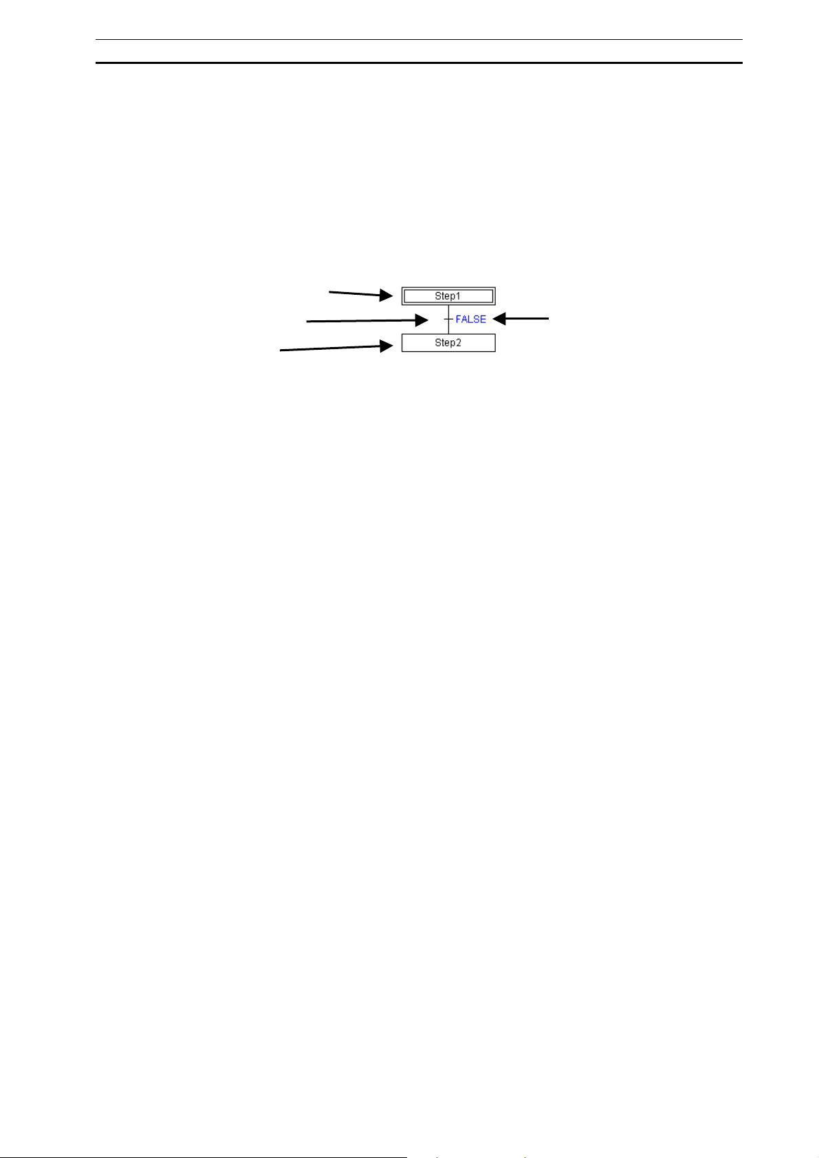
Editing the SFC Chart Section 3-2
3-2 Editing the SFC Chart
This section describes the process of creating an SFC chart using the SFC editor to
connect various SFC elements.
3-2-1 Default Elements of an SFC Program
When a new SFC program is created in the project workspace, the following SFC
elements are automatically generated in the SFC editor.
Initial Step
Transition
Step
Transition Conditions
Initial Step
This is the step that becomes active upon program execution start. It is represented by
a double-line frame.
It will be assigned the name, [Step 1] by default, but this can be changed.
For details, refer to 1-3-6 Environmental Settings Unique to the SFC CX-Programming
Functions.
Transition
The transition conditions (conditions for transferring from the active step to the next
step) are set to the right-hand side of a transition in one of the following ways.
• Bit (Boolean variable or actual address)
• Inputting a ST expression (other than FALSE)
• Inputting a transition program name (ladder or ST)
Transition conditions are set to the ST expression “FALSE” (conditions not fulfilled) by
default.
Step
A step is the box in which the processing details for a single process are stored. It is
represented by a single-line frame.
It will be assigned the name, [Step 2] by default, but this can be changed.
For details, refer to 1-3-6 Environmental Settings Unique to the SFC CX-Programming
Functions.
Processes can be added as “actions” in an action block, for execution upon activation
of the step. There is no limit on the number of actions that can be added.
67
Page 84

Editing the SFC Chart Section 3-2
3-2-2 Editing (Inputting) a Transition
A transition condition can be defined by direct input of a Boolean variable or by an ST
expression.
Alternatively, a transition program can be utilized by specifying the name.
1 To input a transition condition, double-click the target transition, or right-click and
select Edit Transition Condition from the pop-up menu.
The default display (ST expression of “FALSE”) changes to the editable state.
2 Input a Boolean variable (e.g. “a”), an ST expression (e.g. “a=b”), or a transition
program name.
Creating a Transition Program and Defining it as a Transition
A transition program can be created in advance, for use as a transition condition.
Transition programs can be coded in either ladder or ST.
1 Right-click the Transitions folder in the project workspace, and select Insert
Transition – Ladder or Structured Text from the pop-up menu.
68
A transition program (ladder or ST) will be registered under the Transitions folder.
2 Double-click a transition program item (ladder or ST) in the project workspace, or
right-click and select Open from the pop-up menu.
Page 85
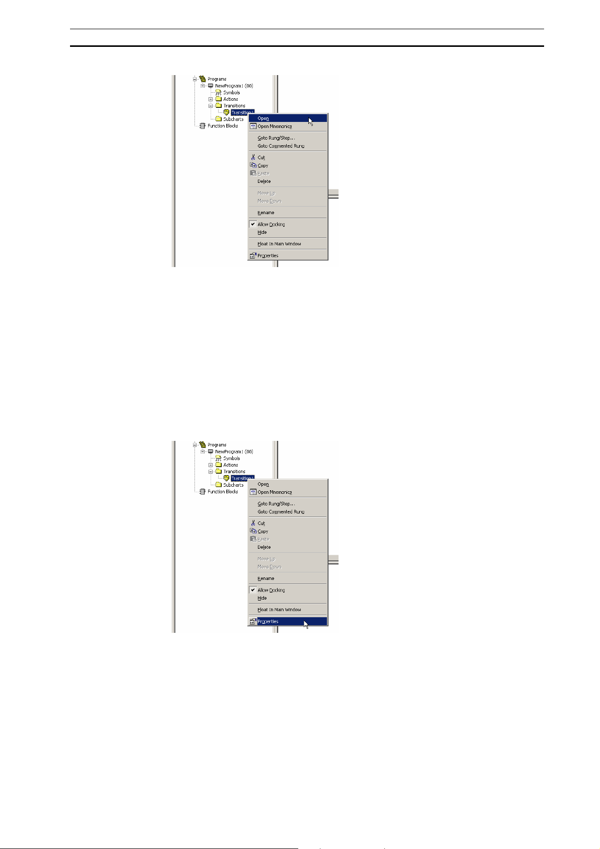
Editing the SFC Chart Section 3-2
The edit window for the transition program (ladder or ST) will open, allowing you to
create the program.
For details on editing in ladder or ST, refer to the CX-Programmer Operation
Manual (Cat. No. W446).
3 Input the name of the transition program as a transition condition.
Assigning a Transition Program Name to a Transition
A transition program can be set as a transition condition by assigning its name to a
transition.
Transition program names can be changed so that they are more self-explanatory.
1 Right-click the Transitions folder in the project workspace, and select Properties
from the pop-up menu.
The Transition Properties dialog is displayed.
2 Under the General tab, input the transition program name into the Name field.
3 Click the close button to close the Transition Properties dialog.
4 Input the new transition program name as a transition condition.
69
Page 86

Editing the SFC Chart Section 3-2
3-2-3 Adding an Action to a Step (or to the Initial Step)
Right-click a step (or the initial step), select Add Action from the pop-up menu, and
select one of the following.
• Boolean Action (Boolean variable or actual address)
• New Ladder Action
• New Structured Text Action
• Existing Action
Adding a Boolean Variable Action Block
Action blocks can be inserted into each step of an SFC chart.
Here, a Boolean variable (bit) action block will be inserted.
1 Select and right-click a step, and select Add Action - Boolean Action from the
pop-up menu.
Note: Multiple action blocks can be inserted into a single step by repeating this procedure. If a
step contains multiple action blocks, they will be executed in sequence from top to bottom.
An action block is inserted to the right of the step.
2 Clicking in the action will display a ‘Browse’ button “[…]”. The Select Symbol dialog
box (shown below) will be displayed.
3 Select a variable from the list shown, or enter a variable name in the Symbol field,
and click OK.
Note: The variables shown are already registered in the local symbol table. If the entered
variable does not currently exist, enter the variable name in the Name field, and click OK.
A prompt to create the variable will be displayed. If ‘Yes’ is selected, then a variable will be
added to the Local Symbol table.
70
Page 87

Editing the SFC Chart Section 3-2
Adding a Ladder Program Action Block and Editing the Ladder Program
Action blocks can be inserted into each step of an SFC chart.
You can insert a ladder program, an ST program, a Boolean variable, or an actual
address as an action block. Here, a ladder program will be inserted as an action block.
1 Select and right-click a step, and select Add Action - New Ladder Action from
the pop-up menu.
Note: Multiple action blocks can be inserted into a single step by repeating this procedure.
2 An action block is inserted to the right of the step.
When the action block is inserted, the program view will switch to the edit window
for ladder programs. Furthermore, a ladder program item will be added to the
project workspace. (An icon will indicate that the item is a ladder program.)
3 Use the program view to edit the ladder action program.
The ladder editing procedure is the same as for CX-Programmer. Refer to the
CX-Programmer Operation Manual (Cat. No. W446).
Adding an ST Program Action Block and Editing the ST Program
Action blocks can be inserted into each step of an SFC chart.
You can insert either a ladder program, an ST program, a Boolean variable, or an
actual address as an action block. Here, an ST program will be inserted as an action
block.
1 Select and right-click a step, and select Add Action - New Structured Text
Action from the pop-up menu.
Note: Multiple action blocks can be inserted into a single step by repeating this procedure.
2 An action block is inserted to the right of the step.
When the action block is inserted, the program view will switch to the edit window
for ST programs. Furthermore, an ST program item will be added to the project
workspace. An icon will indicate that the item is an ST program.
3 Use the program view to edit the ST action program.
The ST editing procedure is the same as for CX-Programmer. Refer to the
71
Page 88

Editing the SFC Chart Section 3-2
CX-Programmer Operation Manual (Cat. No. W446).
Creating an Action Program in Advance and Assigning as an Existing
Program
An action program can be created in advance, and can be assigned to an SFC chart
action block as an “existing action.”
Creating a New Action Program
New action programs can be created in either ladder or ST.
1 Select and right-click an Actions folder in the project workspace, and select Insert
Action - Ladder or Structured Text from the pop-up menu.
An action program (ladder or ST) will be registered under the Actions folder.
2 Double-click the action item (ladder or ST), or right-click and select Open from the
pop-up menu.
The edit window for the action program (ladder or ST) will open, allowing you to
create the program.
For details on editing in ladder or ST, refer to the CX-Programmer Operation
Manual - Function Blocks and Structured Text (Cat. No. W447).
3 Right-click a step, and select Add Action - Existing Action from the pop-up
menu.
4 Right-click the added action block, and select Edit Action Name from the pop-up
menu.
5 Select the action program from the combo list.
72
Page 89

Editing the SFC Chart Section 3-2
Setting AQs (Action Qualifiers)
This section describes how to set an AQ for an action block. One of the 11 AQs must
be set for each action block. The default qualifier is ‘N’.
Multiple action blocks may be inserted into a single step. If a step contains two or more
action blocks, each must be configured independently.
1 Double-click the AQ of an action block, and select an AQ from the combo list.
For specifications on AQ operations, refer to 2-2-3 Action Blocks.
Setting the Timer Unit for a Step Timer
The step timer is started when a step is activated, and when “D”, “L”, “DS” is selected
as the AQ, time control of these actions are executed according to the present value of
the step timer.
The unit of a step timer can be set to seconds or 100 milliseconds.
1 Right-click the step, and select Step Timer - Use Second Timer or Use
Millisecond Timer from the pop-up menu.
73
Page 90

Editing the SFC Chart Section 3-2
Setting the Timer Value for an AQ (Action Qualifier)
When “D”, “L”, “DS”, “SD”, or “SL” is selected as the AQ, the timer value must be set.
Actions are controlled according to the AQ when the step timer reaches the specified
timer value.
1 Right-click an action block, and select Edit Action Qualifier Time from the pop-up
menu.
2 Input the timer value.
0 – 65535 for a one second timer, or 0 – 6553.5 for a millisecond timer.
Note: The unit for the AQ timer value is determined by the step timer setting. Right-click the step,
and select Step Timer - Use Second Timer or Use Millisecond Timer from the pop-up
menu.
Hiding the Action Blocks
Action blocks may be shown/hidden on the SFC chart.
While the action blocks are displayed, right-click the background of the SFC editor and
select Hide All Action Blocks from the pop-up menu.
All action blocks on the SFC chart will be hidden. The number of action block
included in a step will be displayed to the right of each step.
74
Page 91

Editing the SFC Chart Section 3-2
Alternatively, clicking an action on the SFC chart will display the action in the split
window (program view), as will clicking the number for a hidden action block, which
in turn will display a spin box. Change the number to switch the required action
program displayed in the program view.
Showing the Action Blocks
Action blocks may be shown/hidden on the SFC chart.
While the action blocks are hidden, right-click the background of the SFC editor and
select Show All Action Blocks from the pop-up menu.
Note: The actions associated with an individual step may be shown/hidden.
While the action blocks are displayed, right click the required step, and de-select Show
Action Blocks from the pop-up menu.
To display action blocks for an individual step when hidden, right-click the required step,
and select Show Action Blocks from the pop-up menu.
When more than one action is registered, the actions are executed from top down in
the order they are arrange in the action program tree in the workspace.
3-2-4 Adding a Transition
A transition can be added after a step (or subchart step).
1 Right-click a step (or subchart step), and select Add Transition from the pop-up
menu.
Adding a Transition and a Step
A transition and a step can be simultaneously added after a step (or subchart step).
1 Right-click a step (or subchart step), and select Add Transition and Step from the
pop-up menu.
75
Page 92

Editing the SFC Chart Section 3-2
3-2-5 Adding a Step
A step can be added after a transition.
1 Right-click a transition, and select Add Step from the pop-up menu.
Adding a Step and a Transition
A step and a transition can be simultaneously added after a transition.
1 Right-click a transition, and select Add Step and Transition from the pop-up
menu.
76
Page 93

Editing the SFC Chart Section 3-2
3-2-6 Inserting Immediately Before a Step or Transition
Inserting a Step and a Transition Before a Step
A step and a transition can be inserted before a step (or subchart step).
1 Right-click a step (or subchart step), and select Insert Step and Transition
Above from the pop-up menu.
Inserting a Transition and a Step Before a Step
A transition and a step can be inserted before a transition.
1 Right-click a transition, and select Insert Transition and Step Above from the
pop-up menu.
3-2-7 Creating a Divergence/Convergence
Creating a Divergence
Adding 2 Transitions
A divergence can be added after a step (or subchart step).
1 Right-click a step (or subchart step), and select Add Divergence from the pop-up
menu.
77
Page 94

Editing the SFC Chart Section 3-2
A divergence and 2 subsequent transitions will be added.
When using a divergence, add SFC elements so that each branch ends with a
transition, enabling a convergence.
Adding More Transitions
Branches can be added to a divergence.
1 Right-click an existing divergence, and select Add Divergent Transition Branch
from the pop-up menu.
A transition is added to the divergence.
When using a divergence, add SFC elements so that each branch ends with a
transition, enabling a convergence.
78
Creating a Conditional Join
Add a convergence to merge conditionally branched SFC chart process flows.
In order to add a convergence, each conditionally branched process flow must have a
transition as its terminating element.
Right-click one of the conditionally branched transitions, and select Add Convergence
from the pop-up menu.
Page 95

Editing the SFC Chart Section 3-2
A convergence and a subsequent step will be added.
2 Right-click the created convergence, and select Connections - Add Connection
from the pop-up menu.
The Add Connection dialog will be displayed.
3 Confirm that the transitions to be joined are selected in the Add Connection dialog,
and click OK.
The selected transitions will be joined to the convergence.
Note 1: You can also right-click the convergence, select Connections - Add Connection to
Convergence from the pop-up menu, and drag the lead line to the target transition to
connect transitions to a convergence.
2: Right-click the line next to a conditional branch and select Use Default Transition
Precedence to numerically display the execution order starting from 1. Then
double-click the numbers to change the execution order as desired.
3-2-8 Creating a Simultaneous Sequence Divergence/Convergence
Creating a Simultaneous Sequence Divergence
Adding 2 Steps
A simultaneous sequence divergence can be added after a transition.
1 Right-click a transition, and select Add Simultaneous Sequence Divergence
from the pop-up menu.
79
Page 96

Editing the SFC Chart Section 3-2
A simultaneous sequence divergence and 2 subsequent steps will be added.
When using a simultaneous sequence divergence, add SFC elements so that each
branch ends with a step (or subchart step), enabling a simultaneous sequence
convergence.
Adding More Steps
Branches can be added to a simultaneous sequence divergence.
1 Right-click an existing simultaneous sequence divergence, and select Add
Simultaneous Divergent Step Branch from the pop-up menu.
A step is added to the simultaneous sequence divergence.
Creating a Simultaneous Sequence Convergence
Add a simultaneous sequence convergence to merge parallel-branched SFC chart
process flows.
In order to add a simultaneous sequence convergence, each parallel-branched
process flow must have a step (or subchart step) as its terminating element.
1 Right-click one of the branched steps (or subchart steps), and select Add
Simultaneous Sequence Convergence from the pop-up menu.
80
Page 97
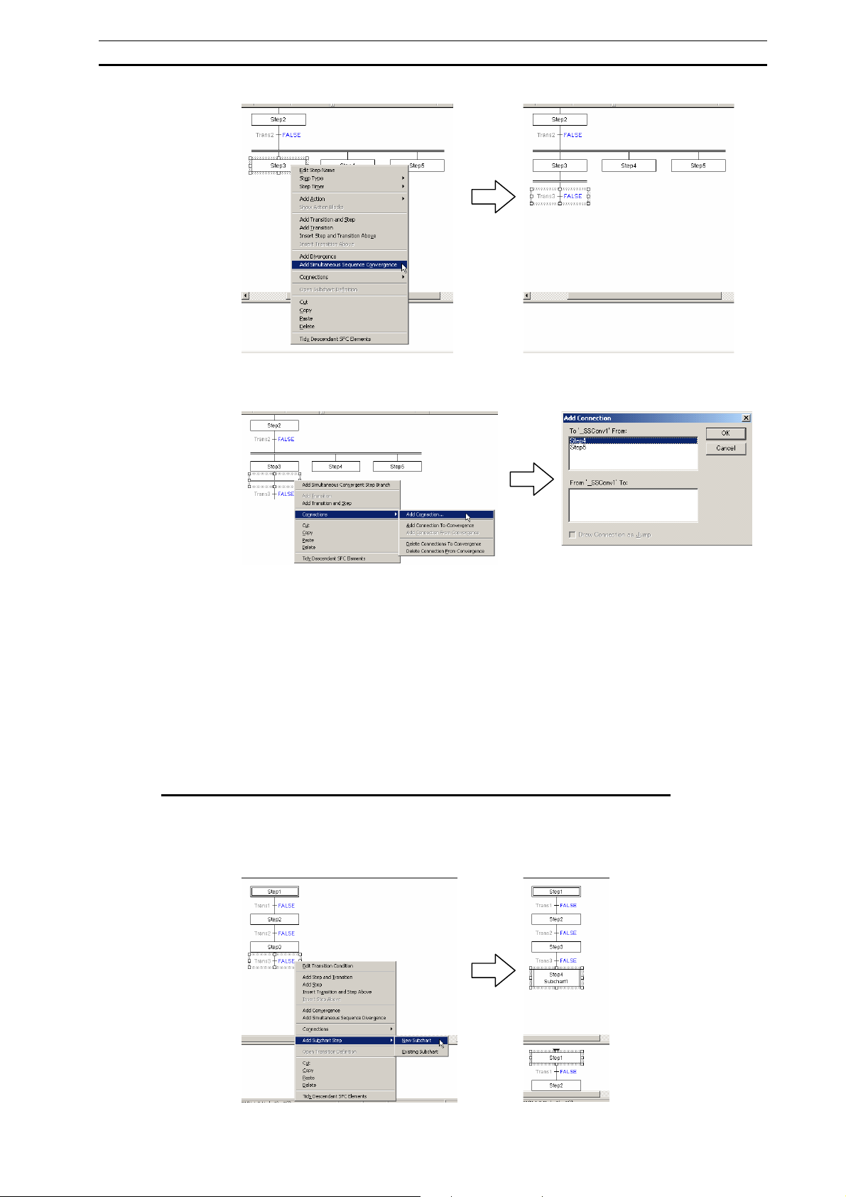
Editing the SFC Chart Section 3-2
A simultaneous sequence convergence and a subsequent transition will be added.
2 Right-click the simultaneous sequence convergence, and select Connections -
Add Connection from the pop-up menu.
The Add Connection dialog will be displayed.
3 Confirm that the transitions to be joined are selected in the Add Connection dialog,
and click OK.
The selected steps (or subchart steps) will be joined to the simultaneous sequence
convergence.
Note: You can also right-click the simultaneous sequence convergence, select Connections -
Add Connection to Convergence from the pop-up menu, and drag the lead line to the
target step to connect steps to a simultaneous sequence convergence.
3-2-9 Adding a Subchart
Adding a Subchart Step and Creating a New Subchart Program
A subchart step can be added after a transition. The subchart program can be created
later.
1 Right-click a transition, and select Add Subchart Step - New Subchart from the
pop-up menu.
81
Page 98
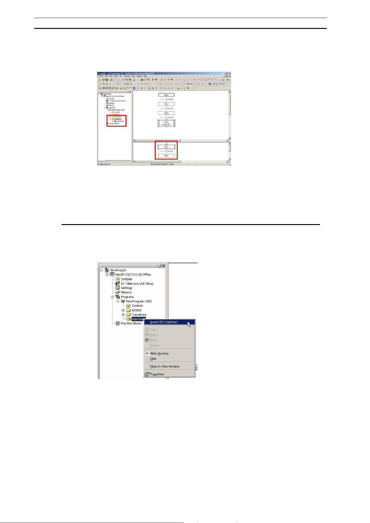
Editing the SFC Chart Section 3-2
When the new subchart step is added, the default SFC subchart will be displayed in
the program view. An SFC subchart item will be added to the Subcharts folder in the
project workspace.
2 Edit the subchart.
The default subchart contains an entry step, a transition, and a step.
Edit the subchart by adding and connecting SFC elements, just as with an SFC
chart.
The first SFC element must be the entry step, and the last must be the return step
Creating a New Subchart Program and Adding an Existing Subchart Step
A subchart program can be created in advance, and used as an “existing subchart” in
adding a subchart step to an SFC chart.
Right-click a Subcharts folder in the project workspace, and select Insert SFC
Subchart from the pop-up menu.
A subchart program will be registered under the Subcharts folder.
3 Double-click the registered subchart program, or right-click and select Open from
the pop-up menu.
82
Page 99

Editing the SFC Chart Section 3-2
The subchart edit window will be displayed. Edit the subchart.
4 Double-click an SFC program in the project workspace, or right-click and select
Open from the pop-up menu.
5 Right-click a transition, and select Add Subchart Step - Existing Subchart from
the pop-up menu.
6 Double-click the subchart step and select the subchart program from the combo
list.
Select from subchart programs that have been registered in the project workspace
as Subcharts folder.
83
Page 100
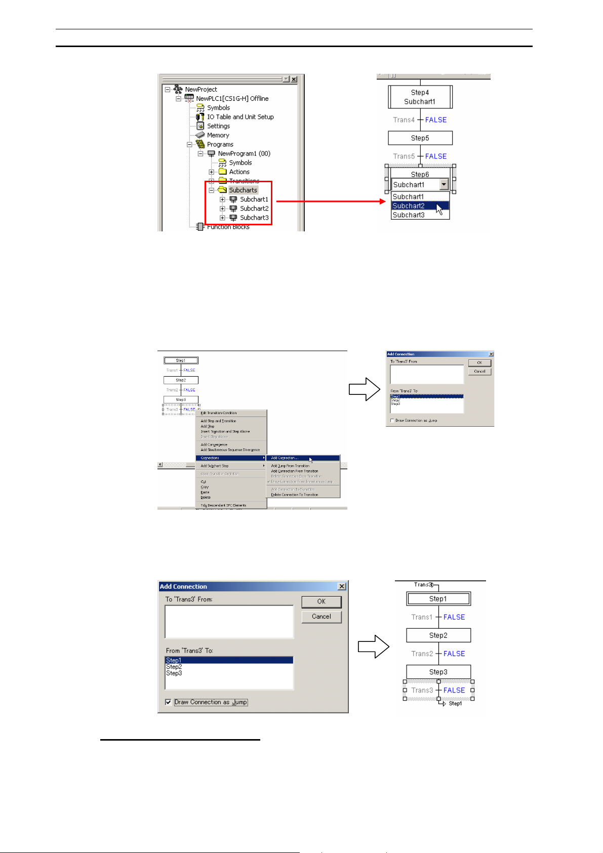
Editing the SFC Chart Section 3-2
3-2-10 Connecting to the Initial Step with a Jump (or Loop)
The bottom transition of an SFC chart can be connected to any other step.
Right-click the bottom transition, and select Connections - Add Connection from the
pop-up menu.
Note: You can also right-click a transition, select Connections - Add Jump from the pop-up
menu, and drag the connection to the jump destination step to establish a connection.
The Add Connection dialog will be displayed.
7 On the Add Connection dialog, select the destination step element.
8 Check the Draw Connection as Jump checkbox and click OK.
Note: For a loop connection, remove the check from Draw Connection as Jump checkbox.
84
Changing a Loop to a Jump
A loop can be changed to a jump.
1 Right-click a loop transition, and select Connections - Draw Connection From
Transition as Jump from the pop-up menu.
 Loading...