

Page 1

Cat. No. W447-E1-08
SYSMAC
CX-Programmer
Ver. 8.1
WS02-CXPC1-V8
OPERATION MANUAL
Function Blocks/
Structured Text
Page 2

CX-Programmer
Ver. 8.1
WS02-CXPC1-V8
Operation Manual
Function Blocks/Structured Text
Revised February 2009
Page 3

iv
Page 4

Notice:
r
f
OMRON products are manufactured for use according to proper procedures by a qualified operator
and only for the purposes described in this manual.
The following conventions are used to indicate and classify precautions in this manual. Always heed
the information provided with them. Failure to heed precautions can result in injury to people or damage to property.
!DANGER Indicates an imminently hazardous situation which, if not avoided, will result in death or
serious injury. Additionally, there may be severe property damage.
!WARNING Indicates a potentially hazardous situation which, if not avoided, could result in death or
serious injury. Additionally, there may be severe property damage.
!Caution Indicates a potentially hazardous situation which, if not avoided, may result in minor or
moderate injury, or property damage.
OMRON Product References
All OMRON products are capitalized in this manual. The word “Unit” is also capitalized when it refers to
an OMRON product, regardless of whether or not it appears in the proper name of the product.
The abbreviation “Ch,” which appears in some displays and on some OMRON products, often means
“word” and is abbreviated “Wd” in documentation in this sense.
The abbreviation “PLC” means Programmable Controller. “PC” is used, however, in some Programming Device displays to mean Programmable Controller.
Visual Aids
The following headings appear in the left column of the manual to help you locate different types of
information.
OMRON, 2008
All rights reserved. No part of this publication may be reproduced, stored in a retrieval system, or transmitted, in any form, o
by any means, mechanical, electronic, photocopying, recording, or otherwise, without the prior written permission o
OMRON.
No patent liability is assumed with respect to the use of the information contained herein. Moreover, because OMRON is constantly striving to improve its high-quality products, the information contained in this manual is subject to change without
notice. Every precaution has been taken in the preparation of this manual. Nevertheless, OMRON assumes no responsibility
for errors or omissions. Neither is any liability assumed for damages resulting from the use of the information contained in
this publication.
Note Indicates information of particular interest for efficient and convenient opera-
tion of the product.
1,2,3... 1. Indicates lists of one sort or another, such as procedures, checklists, etc.
v
Page 5

vi
Page 6

Part 1: Function Block
SECTION 1 Introduction to Function Blocks
SECTION 2 Function Block Specifications
SECTION 3 Creating Function Blocks
Part 2: Structured Text
SECTION 4 Introduction to Structured Text
SECTION 5 Structured Text (ST) Language Specifica-
tions
SECTION 6 Creating ST Programs
Appendices
Page 7

Page 8

TABLE OF CONTENTS
PRECAUTIONS . . . . . . . . . . . . . . . . . . . . . . . . . . . . . . . . . . . xxi
1 Intended Audience. . . . . . . . . . . . . . . . . . . . . . . . . . . . . . . . . . . . . . . . . . . . . . . . . . . . . . . . . xxii
2 General Precautions . . . . . . . . . . . . . . . . . . . . . . . . . . . . . . . . . . . . . . . . . . . . . . . . . . . . . . . . xxii
3 Safety Precautions . . . . . . . . . . . . . . . . . . . . . . . . . . . . . . . . . . . . . . . . . . . . . . . . . . . . . . . . . xxii
4 Application Precautions. . . . . . . . . . . . . . . . . . . . . . . . . . . . . . . . . . . . . . . . . . . . . . . . . . . . . xxiii
Part 1:
Function Blocks
SECTION 1
Introduction to Function Blocks . . . . . . . . . . . . . . . . . . . . . . 3
1-1 Introducing the Function Blocks . . . . . . . . . . . . . . . . . . . . . . . . . . . . . . . . . . . . . . . . . . . . . . 4
1-2 Function Blocks. . . . . . . . . . . . . . . . . . . . . . . . . . . . . . . . . . . . . . . . . . . . . . . . . . . . . . . . . . . 11
1-3 Variables . . . . . . . . . . . . . . . . . . . . . . . . . . . . . . . . . . . . . . . . . . . . . . . . . . . . . . . . . . . . . . . . 18
1-4 Converting Function Block Definitions to Library Files. . . . . . . . . . . . . . . . . . . . . . . . . . . . 23
1-5 Usage Procedures. . . . . . . . . . . . . . . . . . . . . . . . . . . . . . . . . . . . . . . . . . . . . . . . . . . . . . . . . . 23
1-6 Version Upgrade Information . . . . . . . . . . . . . . . . . . . . . . . . . . . . . . . . . . . . . . . . . . . . . . . . 25
SECTION 2
Function Block Specifications . . . . . . . . . . . . . . . . . . . . . . . . 29
2-1 Function Block Specifications. . . . . . . . . . . . . . . . . . . . . . . . . . . . . . . . . . . . . . . . . . . . . . . . 30
2-2 Data Types Supported in Function Blocks . . . . . . . . . . . . . . . . . . . . . . . . . . . . . . . . . . . . . . 41
2-3 Instance Specifications . . . . . . . . . . . . . . . . . . . . . . . . . . . . . . . . . . . . . . . . . . . . . . . . . . . . . 42
2-4 Programming Restrictions . . . . . . . . . . . . . . . . . . . . . . . . . . . . . . . . . . . . . . . . . . . . . . . . . . .51
2-5 Function Block Applications Guidelines . . . . . . . . . . . . . . . . . . . . . . . . . . . . . . . . . . . . . . . . 56
2-6 Precautions for Instructions with Operands Specifying the First or Last of Multiple Words 65
2-7 Instruction Support and Operand Restrictions. . . . . . . . . . . . . . . . . . . . . . . . . . . . . . . . . . . . 68
2-8 CPU Unit Function Block Specifications . . . . . . . . . . . . . . . . . . . . . . . . . . . . . . . . . . . . . . . 70
2-9 Number of Function Block Program Steps and Instance Execution Time . . . . . . . . . . . . . . 76
SECTION 3
Creating Function Blocks. . . . . . . . . . . . . . . . . . . . . . . . . . . . 79
3-1 Procedural Flow. . . . . . . . . . . . . . . . . . . . . . . . . . . . . . . . . . . . . . . . . . . . . . . . . . . . . . . . . . . 80
3-2 Procedures . . . . . . . . . . . . . . . . . . . . . . . . . . . . . . . . . . . . . . . . . . . . . . . . . . . . . . . . . . . . . . . 82
ix
Page 9

TABLE OF CONTENTS
Part 2:
Structured Text (ST)
SECTION 4
Introduction to Structured Text . . . . . . . . . . . . . . . . . . . . . . 131
4-1 ST Language . . . . . . . . . . . . . . . . . . . . . . . . . . . . . . . . . . . . . . . . . . . . . . . . . . . . . . . . . . . . . 132
4-2 CX-Programmer Specifications. . . . . . . . . . . . . . . . . . . . . . . . . . . . . . . . . . . . . . . . . . . . . . . 133
SECTION 5
Structured Text (ST) Language Specifications . . . . . . . . . . 135
5-1 Structured Text Language Specifications . . . . . . . . . . . . . . . . . . . . . . . . . . . . . . . . . . . . . . . 136
5-2 Data Types Used in ST Programs . . . . . . . . . . . . . . . . . . . . . . . . . . . . . . . . . . . . . . . . . . . . . 137
5-3 Inputting ST Programs. . . . . . . . . . . . . . . . . . . . . . . . . . . . . . . . . . . . . . . . . . . . . . . . . . . . . . 138
5-4 ST Language Configuration . . . . . . . . . . . . . . . . . . . . . . . . . . . . . . . . . . . . . . . . . . . . . . . . . 141
5-5 Statement Descriptions . . . . . . . . . . . . . . . . . . . . . . . . . . . . . . . . . . . . . . . . . . . . . . . . . . . . . 148
5-6 ST-language Program Example . . . . . . . . . . . . . . . . . . . . . . . . . . . . . . . . . . . . . . . . . . . . . . . 166
5-7 Restrictions . . . . . . . . . . . . . . . . . . . . . . . . . . . . . . . . . . . . . . . . . . . . . . . . . . . . . . . . . . . . . . 167
SECTION 6
Creating ST Programs . . . . . . . . . . . . . . . . . . . . . . . . . . . . . . 169
6-1 Procedures . . . . . . . . . . . . . . . . . . . . . . . . . . . . . . . . . . . . . . . . . . . . . . . . . . . . . . . . . . . . . . . 170
Appendices
A System-defined external variables supported in function blocks . . . . . . . . . . . . . . . . . . . . . 181
B Structured Text Errors . . . . . . . . . . . . . . . . . . . . . . . . . . . . . . . . . . . . . . . . . . . . . . . . . . . . . . 183
C Function Descriptions . . . . . . . . . . . . . . . . . . . . . . . . . . . . . . . . . . . . . . . . . . . . . . . . . . . . . . 187
Index. . . . . . . . . . . . . . . . . . . . . . . . . . . . . . . . . . . . . . . . . . . . . 201
Revision History . . . . . . . . . . . . . . . . . . . . . . . . . . . . . . . . . . . 203
x
Page 10
About this Manual:
This manual describes the CX-Programmer operations that are related to the function block functions
and Structured Text (ST) functions. The function block and structure text functionality of CX-Programmer Ver. 8.1 is supported by CJ2H CPU Units, by CS1-H, CJ1-H, and CJ1M CPU Units with unit version 3.0 or later, by CP-series CPU Units, and by NSJ-series and FQM1-series Controllers.
Some function block and structure text functionality, however, is supported only by CJ2H CPU Units, by
CS1-H, CJ1-H, and CJ1M CPU Units with unit version 4.0 or later.
For details, refer to 1-6 Version Upgrade Information.
For information on functionality other than function blocks and structure text, refer to the following manuals.
• CX-Programmer
: CX-Programmer Operation Manual (W446) and CX-Programmer Operation Manual: SFC (W469)
• CPU Unit
: The operation manuals for the CS-series, CJ-series, CP-series, and NSJ-series Controllers
CX-Programmer Ver. 8.1 Manuals
Name Cat. No. Contents
SYSMAC WS02-CXPC1-V8
CX-Programmer Ver. 8.1 Operation Manual
Function Blocks/Structured Text
SYSMAC WS02-CXPC1-V8
CX-Programmer Operation Manual
SYSMAC WS02-CXPC1-V8
CX-Programmer Operation Manual: SFC
CX-Net Operation Manual W362 Information on setting up networks, such as setting data links,
SYSMAC CXONE-AL
SYSMAC CXONE-AL
CX-Integrator Operation Manual
@@C-V3
@@D-V3
W447
(this
manual)
W446 Provides information on how to use the CX-Programmer for
W469 Explains how to use the SFC programming functions. For
W445 Describes the operating procedures for the CX-Integrator.
Explains how to use the CX-Programmer Ver. 8.1 software’s
function block and structured text functions. For explanations
of other shared CX-Programmer functions, refer to the CX-
Programmer Operation Manual (W446).
all functionality except for function blocks.
explanations of other shared CX-Programmer functions, refer
to the CX-Programmer Operation Manual (W446).
routing tables, and unit settings.
xi
Page 11

CS1-H, CJ1-H, and CJ1M CPU Unit Manuals
Name Cat. No. Contents
SYSMAC CJ Series
CJ2H-CPU6@-EIP, CJ2H-CPU6@
Programmable Controllers
Hardware User's Manual
SYSMAC CJ Series
CJ2H-CPU6@-EIP, CJ2H-CPU6@
Programmable Controllers
Software User's Manual
SYSMAC CS/CJ Series
CS1G/H-CPU@@ -EV1, CS1G/H-CPU@@H,
CS1D-CPU@@H, CS1D-CPU@@S,
CJ2H-CPU6@-EIP, CJ2H-CPU6@,
CJ1H-CPU@@H-R
CJ1G-CPU@@, CJ1G/H-CPU@@H,
CJ1G-CPU@@P, C J 1 M - C P U @@
SYSMAC One NSJ Series
NSJ@-@@@@(B)-G5D
NSJ@-@@@@(B)-M3D
Programmable Controllers
Instructions Reference Manual
SYSMAC CS Series
CS1G/H-CPU@@-EV1, CS1G/H-CPU@@H
Programmable Controllers
Operation Manual
SYSMAC CJ Series
CJ1G-CPU@@, CJ1G/H-CPU@@H,
CJ1H-CPU@@H-R, CJ1G-CPU@@P,
CJ1M-CPU@@
Programmable Controllers
Operation Manual
W472 Provides an outline of and describes the design, installation,
maintenance, and other basic operations for the CJ-series
CJ2 CPU Units.
The following information is included:
Overview and features
System configuration
Installation and wiring
Troubleshooting
Use this manual together with the W473.
W473 Describes programming and other methods to use the func-
tions of the CJ2 CPU Units.
The following information is included:
CPU Unit operation
Internal memory areas
Programming
Tasks
CPU Unit built-in functions
Use this manual together with the W472.
W474 Describes the ladder diagram programming instructions sup-
ported by CS/CJ-series or NSJ-series PLCs.
When programming, use this manual together with the Oper-
ation Manual or Hardware User's Manual (CS1: W339, CJ1:
W393,or CJ2:W472) and Programming Manual or Software
User's Manual (CS1/CJ1:W394 or CJ2:W473).
W339 Provides an outline of and describes the design, installation,
maintenance, and other basic operations for the CS-series
PLCs.
The following information is included:
An overview and features
The system configuration
Installation and wiring
I/O memory allocation
Troubleshooting
Use this manual together with the W394.
W393 Provides an outline of and describes the design, installation,
maintenance, and other basic operations for the CJ-series
PLCs.
The following information is included:
An overview and features
The system configuration
Installation and wiring
I/O memory allocation
Troubleshooting
Use this manual together with the W394.
xii
Page 12

Name Cat. No. Contents
SYSMAC CS/CJ Series
CS1G/H-CPU@@-EV1, CS1G/H-CPU@@H,
CJ1G-CPU@@, CJ1G/H-CPU@@H,
CJ1H-CPU@@H-R, CJ1G-CPU@@P,
CJ1M-CPU@@, NSJ@-@@@@(B)-G5D,
NSJ@-@@@@(B)-M3D
Programmable Controllers
Programming Manual
SYSMAC CS/CJ Series
CS1G/H-CPU@@-EV1, CS1G/H-CPU@@H,
CJ1G-CPU@@, CJ1G/H-CPU@@H,
CJ1H-CPU@@H-R, CJ1G-CPU@@P,
CJ1M-CPU@@, NSJ@-@@@@(B)-G5D,
NSJ@-@@@@(B)-M3D
Programmable Controllers
Instructions Reference Manual
CS1G/H-CPU@@-EV1
CS1G/H-CPU@@H
CS1W-SCB21-V1/41-V1
CS1W-SCU21/41
CJ2H-CPU6@-EIP, CJ2H-CPU6@
CJ1G-CPU@@
CJ1G/H-CPU@@H
CJ1G-CPU@@P
CJ1M-CPU@@
CJ1W-SCU21-V1/41-V1
CP1H-X@@@@-@
CP1H-XA@@@@-@
CP1H-Y@@@@-@
NSJ@-@@@@(B)-G5D
NSJ@-@@@@(B)-M3D
SYSMAC CS/CJ Series Communications
Commands Reference Manual
W394 Describes programming and other methods to use the func-
tions of the CS/CJ-series and NSJ-series PLCs.
The following information is included:
Programming
Tasks
File memory
Other functions
Use this manual together with the W339 or W393.
W340 Describes the ladder diagram programming instructions sup-
ported by CS/CJ-series and NSJ-series PLCs.
When programming, use this manual together with the Oper-
ation Manual (CS1: W339 or CJ1: W393) and Programming
Manual (W394).
W342 Describes the communications commands that can be
addressed to CS/CJ-series CPU Units.
The following information is included:
C-series (Host Link) commands
FINS commands
Note: This manual describes commands that can be sent to
the CPU Unit without regard for the communications path,
which can be through a serial communications port on the
CPU Unit, a communications port on a Serial Communications Unit/Board, or a port on any other Communications
Unit.
NSJ-series NSJ Controller Manual
Refer to the following manual for NSJ-series NSJ Controller specifications and handling methods not
given in this manual.
Cat. No. Models Name Description
W452 NSJ5-TQ@@(B)-G5D
NSJ5-SQ@@(B)-G5D
NSJ8-TV@@(B)-G5D
NSJ10-TV@@(B)-G5D
NSJ12-TS@@(B)-G5D
NSJ Series
Operation
Manual
Provides the following information about the NSJ-series NSJ Controllers:
Overview and features
Designing the system configuration
Installation and wiring
I/O memory allocations
Troubleshooting and maintenance
Use this manual in combination with the following manuals: SYS-
MAC CS Series Operation Manual (W339), SYSMAC CJ Series
Operation Manual (W393), SYSMAC CS/CJ Series Programming
Manual (W394), and NS-V1/-V2 Series Setup Manual (V083)
xiii
Page 13
FQM1 Series Manuals (Unit Version 3.0 or Later)
Refer to the following manuals for specifications and handling methods not given in this manual for
FQM1 Series unit version 3.0 (FQM1-CM002/MMP22/MMA22).
Cat. No. Models Name Description
O012 FQM1-CM002
FQM1-MMP22
FQM1-MMA22
O013 FQM1-CM002
FQM1-MMP22
FQM1-MMA22
FQM1 Series
Operation Manual
FQM1 Series
Instructions
Reference Manual
Provides the following information about the FQM1-series Modules
(unit version 3.0):
Overview and features
Designing the system configuration
Installation and wiring
I/O memory allocations
Troubleshooting and maintenance
Individually describes the instructions used to program the FQM1.
Use this manual in combination with the FQM1 Series
Operation Manual (O012) when programming.
CP-series PLC Unit Manuals
Refer to the following manuals for specifications and handling methods not given in this manual for CPseries CPU Units.
Cat. No. Models Name Description
W450 CP1H-X@@@@-@
CP1H-XA@@@@-@
CP1H-Y@@@@-@
W462 CP1L-M@@@@-@
CP1L-L@@@@-@
W451 CP1H-X@@@@-@
CP1H-XA@@@@-@
CP1H-Y@@@@-@
CP1L-M@@@@-@
CP1L-L@@@@-@
SYSMAC CP Series
CP1H CPU Unit
Operation Manual
SYSMAC CP Series
CP1L CPU Unit Operation Manual
SYSMAC CP Series
CP1H/CP1L CPU
Unit Programming
Manual
Provides the following information on the CP-series CP1H PLCs:
• Overview/Features
• System configuration
• Mounting and wiring
• I/O memory allocation
• Troubleshooting
Use this manual together with the CP1H/CP1L Programmable
Controllers Programming Manual (W451).
Provides the following information on the CP-series CP1L PLCs:
• Overview/Features
• System configuration
• Mounting and wiring
• I/O memory allocation
• Troubleshooting
Use this manual together with the CP1H Programmable Control-
lers Programming Manual (W451).
Provides the following information on the CP-series CP1H and
CP1L PLCs:
• Programming instructions
• Programming methods
• Tasks
Use this manual together with the CP1H/CP1L Programmable
Controllers Operation Manual (W450).
Installation from CX-One
For details on procedures for installing the CX-Programmer from CX-One FA Integrated Tool Package,
refer to the CX-One Ver. 3.0 Setup Manual provided with CX-One.
Cat. No. Model Manual name Contents
W463 CXONE-AL@@C-V3/
AL@@D-V3
xiv
CX-One Setup Manual Installation and overview of CX-One FA
Integrated Tool Package.
Page 14

Overview of Contents
Precautions provides general precautions for using the CX-Programmer Ver. 8.1.
Part 1
Part 1 contains the following sections.
Section 1 introduces the function block functionality of the CX-Programmer and explains the features
that are not contained in the non-function block version of CX-Programmer.
Section 2 provides specifications for reference when using function blocks, including specifications on
function blocks, instances, and compatible PLCs, as well as usage precautions and guidelines.
Section 3 describes the procedures for creating function blocks on the CX-Programmer.
Part 2
Part 2 contains the following sections.
Section 4 introduces the structure text programming functionality of the CX-Programmer and explains
the features that are not contained in the non-structured text version of CX-Programmer.
Section 5 provides specifications for reference when using structured text programming, as well as
programming examples and restrictions.
Section 6 explains how to create ST programs.
Appendices provide information on structured text errors and ST function descriptions.
!WARNING Failure to read and understand the information provided in this manual may result in per-
sonal injury or death, damage to the product, or product failure. Please read each section
in its entirety and be sure you understand the information provided in the section and
related sections before attempting any of the procedures or operations given.
xv
Page 15

xvi
Page 16

Read and Understand this Manual
Please read and understand this manual before using the product. Please consult your OMRON
representative if you have any questions or comments.
Warranty and Limitations of Liability
WARRANTY
(1) The warranty period for the Software is one year from either the date of purchase or the date on which
the Software is delivered to the specified location.
(2) If the User discovers a defect in the Software (i.e., substantial non-conformity with the manual), and
returns it to OMRON within the above warranty period, OMRON will replace the Software without charge
by offering media or downloading services from the Internet. And if the User discovers a defect in the
media which is attributable to OMRON and returns the Software to OMRON within the above warranty
period, OMRON will replace the defective media without charge. If OMRON is unable to replace the
defective media or correct the Software, the liability of OMRON and the User's remedy shall be limited to
a refund of the license fee paid to OMRON for the Software.
LIMITATIONS OF LIABILITY
(1) THE ABOVE WARRANTY SHALL CONSTITUTE THE USER'S SOLE AND EXCLUSIVE REMEDIES
AGAINST OMRON AND THERE ARE NO OTHER WARRANTIES, EXPRESSED OR IMPLIED,
INCLUDING BUT NOT LIMITED TO, WARRANTY OF MERCHANTABILITY OR FITNESS FOR A
PARTICULAR PURPOSE. IN NO EVENT WILL OMRON BE LIABLE FOR ANY LOST PROFITS OR
OTHER INDIRECT, INCIDENTAL, SPECIAL, OR CONSEQUENTIAL DAMAGES ARISING OUT OF
USE OF THE SOFTWARE.
(2) OMRON SHALL ASSUME NO LIABILITY FOR DEFECTS IN THE SOFTWARE BASED ON
MODIFICATION OR ALTERATION OF THE SOFTWARE BY THE USER OR ANY THIRD PARTY.
(3) OMRON SHALL ASSUME NO LIABILITY FOR SOFTWARE DEVELOPED BY THE USER OR ANY
THIRD PARTY BASED ON THE SOFTWARE OR ANY CONSEQUENCE THEREOF.
xvii
Page 17

Application Considerations
SUITABILITY FOR USE
THE USER SHALL NOT USE THE SOFTWARE FOR A PURPOSE THAT IS NOT DESCRIBED IN THE
ATTACHED USER MANUAL.
xviii
Page 18

Disclaimers
CHANGE IN SPECIFICATIONS
The software specifications and accessories may be changed at any time based on improvements or for
other reasons.
EXTENT OF SERVICE
The license fee of the Software does not include service costs, such as dispatching technical staff.
ERRORS AND OMISSIONS
The information in this manual has been carefully checked and is believed to be accurate; however, no
responsibility is assumed for clerical, typographical, or proofreading errors, or omissions.
xix
Page 19

xx
Page 20

PRECAUTIONS
This section provides general precautions for using the CX-Programmer and the Programmable Logic Controller.
The information contained in this section is important for the safe and reliable application of the CX-Programmer
and Programmable Controller. You must read this section and understand the information contained before
attempting to set up or operate the CX-Programmer and Programmable Controller.
1 Intended Audience . . . . . . . . . . . . . . . . . . . . . . . . . . . . . . . . . . . . . . . . . . . . . xxii
2 General Precautions . . . . . . . . . . . . . . . . . . . . . . . . . . . . . . . . . . . . . . . . . . . . xxii
3 Safety Precautions. . . . . . . . . . . . . . . . . . . . . . . . . . . . . . . . . . . . . . . . . . . . . . xxii
4 Application Precautions . . . . . . . . . . . . . . . . . . . . . . . . . . . . . . . . . . . . . . . . . xxiii
xxi
Page 21

Intended Audience 1
1 Intended Audience
This manual is intended for the following personnel, who must also have
knowledge of electrical systems (an electrical engineer or the equivalent).
• Personnel in charge of installing FA systems.
• Personnel in charge of designing FA systems.
• Personnel in charge of managing FA systems and facilities.
2 General Precautions
The user must operate the product according to the performance specifications described in the operation manuals.
Before using the product under conditions which are not described in the
manual or applying the product to nuclear control systems, railroad systems,
aviation systems, vehicles, combustion systems, medical equipment, amusement machines, safety equipment, and other systems, machines, and equipment that may have a serious influence on lives and property if used
improperly, consult your OMRON representative.
Make sure that the ratings and performance characteristics of the product are
sufficient for the systems, machines, and equipment, and be sure to provide
the systems, machines, and equipment with double safety mechanisms.
This manual provides information for programming and operating the product.
Be sure to read this manual before attempting to use the product and keep
this manual close at hand for reference during operation.
!WARNING It is extremely important that a PLC and all PLC Units be used for the speci-
fied purpose and under the specified conditions, especially in applications that
can directly or indirectly affect human life. You must consult with your OMRON
representative before applying a PLC System to the above-mentioned applications.
3 Safety Precautions
!WARNING Confirm safety sufficiently before transferring I/O memory area status from the
CX-Programmer to the actual CPU Unit. The devices connected to Output
Units may malfunction, regardless of the operating mode of the CPU Unit.
Caution is required in respect to the following functions.
• Transferring from the CX-Programmer to real I/O (CIO Area) in the CPU
Unit using the PLC Memory Window.
• Transferring from file memory to real I/O (CIO Area) in the CPU Unit using
the Memory Card Window.
!Caution Variables must be specified either with AT settings (or external variables), or
the variables must be the same size as the data size to be processed by the
instruction when specifying the first or last address of multiple words in the
instruction operand.
xxii
1. If a non-array variable with a different data size and without an AT setting
is specified, the CX-Programmer will output an error when compiling.
2. Array Variable Specifications
Page 22

Application Precautions 4
• When the size to be processed by the instruction operand is fixed:
The number of array elements must be the same as the number of elements to be processed by the instruction. Otherwise, the CX-Programmer
will output an error when compiling.
• When the size to be processed by the instruction operand is not fixed:
The number of array elements must be greater than or the same as the
size specified in the other operands.
• If the other operand specifying a size is a constant, the CX-Programmer will output an error when compiling.
• If the other operand specifying a size is a variable, the CX-Programmer
will not output an error when compiling, even if the size of the array
variable is not the same as that specified by the other operand (variable). A warning message, however, will be displayed. In particular, if
the number of array elements is less than the size specified by the other operand (e.g., the size of the instruction operand is 16, and the number of elements registered in the actual variable table is 10), the
instruction will execute read/write processing for the area that exceeds
the number of elements. For example, read/write processing will be executed for the 6 words following those for the number of elements registered in the actual variable table. If these words are used for other
instructions (including internal variable allocations), unexpected operation will occur, which may result in serious accidents.
Check that the system will not be adversely affected if the size of the
variable specified in the operand is less than the size in the operand
definition before starting PLC operations.
!Caution Confirm safety at the destination node before transferring a program to
another node or changing contents of the I/O memory area. Doing either of
these without confirming safety may result in injury.
!Caution Execute online editing only after confirming that no adverse effects will be
caused by extending the cycle time. Otherwise, the input signals may not be
readable.
!Caution If synchronous unit operation is being used, perform online editing only after
confirming that an increased synchronous processing time will not affect the
operation of the main and slave axes.
!Caution Confirm safety sufficiently before monitoring power flow and present value
status in the Ladder Section Window or when monitoring present values in the
Watch Window. If force-set/reset or set/reset operations are inadvertently performed by pressing short-cut keys, the devices connected to Output Units
may malfunction, regardless of the operating mode of the CPU Unit.
4 Application Precautions
Observe the following precautions when using the CX-Programmer.
• User programs cannot be uploaded to the CX-Programmer.
• Observe the following precautions before starting the CX-Programmer.
• Exit all applications not directly related to the CX-Programmer. Particularly exit any software such as screen savers, virus checkers, E-mail
or other communications software, and schedulers or other applications that start up periodically or automatically.
xxiii
Page 23

Application Precautions 4
• Disable sharing hard disks, printers, or other devices with other computers on any network.
• With some notebook computers, the RS-232C port is allocated to a
modem or an infrared line by default. Following the instructions in documentation for your computer and enable using the RS-232C port as
a normal serial port.
• With some notebook computers, the default settings for saving energy
do not supply the rated power to the RS-232C port. There may be both
Windows settings for saving energy, as well as setting for specific computer utilities and the BIOS. Following the instructions in documentation for your computer, disable all energy saving settings.
• Do not turn OFF the power supply to the PLC or disconnect the connecting cable while the CX-Programmer is online with the PLC. The computer
may malfunction.
• Confirm that no adverse effects will occur in the system before attempting
any of the following. Not doing so may result in an unexpected operation.
• Changing the operating mode of the PLC.
• Force-setting/force-resetting any bit in memory.
• Changing the present value of any word or any set value in memory.
• Check the user program for proper execution before actually running it on
the Unit. Not checking the program may result in an unexpected operation.
• When online editing is performed, the user program and parameter area
data in CJ2, CS1-H, CJ1-H, CJ1M, and CP1H CPU Units is backed up in
the built-in flash memory. The BKUP indicator will light on the front of the
CPU Unit when the backup operation is in progress. Do not turn OFF the
power supply to the CPU Unit when the BKUP indicator is lit. The data will
not be backed up if power is turned OFF. To display the status of writing to
flash memory on the CX-Programmer, select Display dialog to show PLC
Memory Backup Status in the PLC properties and then select Windows -
PLC Memory Backup Status from the View Menu.
• Programs including function blocks (ladder programming language or
structured text (ST) language) can be downloaded or uploaded in the
same way as standard programs that do not contain function blocks.
Tasks including function blocks, however, cannot be downloaded in task
units (uploading is possible).
• If a user program containing function blocks created on the CX-Programmer Ver. 5.0 or later is downloaded to a CPU Unit that does not support
function blocks (CS/CJ-series CPU Units with unit version 2.0 or earlier),
all instances will be treated as illegal commands and it will not be possible
to edit or execute the user program.
• If the input variable data is not in boolean format, and numerical values
only (e.g., 20) are input in the parameters, the actual value in the CIO
Area address (e.g., 0020) will be passed. Therefore, be sure to include an
&, #, or +, - prefix before inputting the numerical value.
• Addresses can be set in input parameters, but an address itself cannot be
passed as an input variable. (Even if an address is set as an input parameter, the value passed to the function block will be that for the size of data
of the input variable.) Therefore, an input variable cannot be used as the
operand of an instruction in the function block when the operand specifies
the first or last of multiple words. With CX-Programmer version 7.0, use
xxiv
Page 24

Application Precautions 4
an input-output variable specified as an array variable (with the first
address set for the input parameter) and specify the first or last element of
the array variable, or, with any version of CX-Programmer, use an internal
variable with an AT setting. Alternatively, specify the first or last element in
an internal variable specified as an array variable.
• Values are passed in a batch from the input parameters to the input variables or input-output variables before algorithm execution (not at the
same time as the instructions in the algorithm are executed). Therefore, to
pass the value from a parameter to an input variable or input-output variable when an instruction in the function block algorithm is executed, use
an internal variable or external variable instead of an input variable or
input-output variable. The same applies to the timing for writing values to
the parameters from output variables.
• Always use internal variables with AT settings in the following cases.
• The addresses allocated to Basic I/O Units, Special I/O Units, and
CPU Bus Units cannot be registered to global symbols, and these variables cannot be specified as external variables (e.g., the data set for
global variables may not be stable).
• Use internal variables when Auxiliary Area bits other than those preregistered to external variables are registered to global symbols and
these variables are not specified as external variables.
• Use internal variables when specifying PLC addresses for another
node on the network: For example, the first destination word at the remote node for SEND(090) and the first source word at the remote node
for RECV(098).
• Use internal variables when the first or last of multiple words is specified by an instruction operand and the operand cannot be specified as
an array variable (e.g., the number of array elements cannot be specified).
xxv
Page 25

Application Precautions 4
xxvi
Page 26

Part 1:
Function Blocks
Page 27

Page 28

SECTION 1
Introduction to Function Blocks
This section introduces the function block functionality of the CX-Programmer and explains the features that are not
contained in the non-function block version of CX-Programmer.
1-1 Introducing the Function Blocks. . . . . . . . . . . . . . . . . . . . . . . . . . . . . . . . . . . 4
1-1-1 Overview and Features . . . . . . . . . . . . . . . . . . . . . . . . . . . . . . . . . . . 4
1-1-2 Function Block Specifications . . . . . . . . . . . . . . . . . . . . . . . . . . . . . 5
1-1-3 Files Created with CX-Programmer Ver. 6.0 or Later . . . . . . . . . . . 8
1-1-4 Function Block Menus in CX-Programmer Ver. 5.0
(and later Versions). . . . . . . . . . . . . . . . . . . . . . . . . . . . . . . . . . . . . . 8
1-2 Function Blocks . . . . . . . . . . . . . . . . . . . . . . . . . . . . . . . . . . . . . . . . . . . . . . . 11
1-2-1 Outline . . . . . . . . . . . . . . . . . . . . . . . . . . . . . . . . . . . . . . . . . . . . . . . 11
1-2-2 Advantages of Function Blocks . . . . . . . . . . . . . . . . . . . . . . . . . . . . 12
1-2-3 Function Block Structure . . . . . . . . . . . . . . . . . . . . . . . . . . . . . . . . . 13
1-3 Variables . . . . . . . . . . . . . . . . . . . . . . . . . . . . . . . . . . . . . . . . . . . . . . . . . . . . . 18
1-3-1 Introduction. . . . . . . . . . . . . . . . . . . . . . . . . . . . . . . . . . . . . . . . . . . . 18
1-3-2 Variable Usage and Properties . . . . . . . . . . . . . . . . . . . . . . . . . . . . . 19
1-3-3 Variable Properties . . . . . . . . . . . . . . . . . . . . . . . . . . . . . . . . . . . . . . 19
1-3-4 Variable Properties and Variable Usage . . . . . . . . . . . . . . . . . . . . . . 20
1-3-5 Internal Allocation of Variable Addresses . . . . . . . . . . . . . . . . . . . . 21
1-4 Converting Function Block Definitions to Library Files . . . . . . . . . . . . . . . . 23
1-5 Usage Procedures . . . . . . . . . . . . . . . . . . . . . . . . . . . . . . . . . . . . . . . . . . . . . . 23
1-5-1 Creating Function Blocks and Executing Instances . . . . . . . . . . . . . 23
1-5-2 Reusing Function Blocks . . . . . . . . . . . . . . . . . . . . . . . . . . . . . . . . . 24
1-6 Version Upgrade Information . . . . . . . . . . . . . . . . . . . . . . . . . . . . . . . . . . . . . 25
3
Page 29

Introducing the Function Blocks Section 1-1
1-1 Introducing the Function Blocks
1-1-1 Overview and Features
The CX-Programmer Ver. 5.0 (and later versions) is a Programming Device
that can use standard IEC 61131-3 function blocks. The CX-Programmer
function block function is supported for CJ2H CPU Units, CP1H CPU Units,
NSJ-series NSJ Controllers, and FQM1 Flexible Motion Controllers as well as
CS/CJ-series CPU Units with unit version 3.0 or later and has the following
features.
• User-defined processes can be converted to block format by using function blocks.
• Function block algorithms can be written in the ladder programming language or in the structured text (ST) language. (See note.)
• When ladder programming is used, ladder programs created with nonCX-Programmer Ver. 4.0 or earlier can be reused by copying and pasting.
• When ST language is used, it is easy to program mathematical processes that would be difficult to enter with ladder programming.
Note The ST language is an advanced language for industrial control
(primarily Programmable Logic Controllers) that is described in IEC
61131-3. The ST language supported by CX-Programmer conforms to the IEC 61131-3 standard.
• Function blocks can be created easily because variables do not have to
be declared in text. They are registered in variable tables.
A variable can be registered automatically when it is entered in a ladder or
ST program. Registered variables can also be entered in ladder programs
after they have been registered in the variable table.
• A single function block can be converted to a library function as a single
file, making it easy to reuse function blocks for standard processing.
• A program check can be performed on a single function block to easily
confirm the function block’s reliability as a library function.
• Programs containing function blocks (ladder programming language or
structured text (ST) language) can be downloaded or uploaded in the
same way as standard programs that do not contain function blocks.
Tasks containing function blocks, however, cannot be downloaded in task
units (uploading is possible).
• One-dimensional array variables are supported, so data handling is easier for many applications.
Note The IEC 61131 standard was defined by the International Electro-
technical Commission (IEC) as an international programmable logic controller (PLC) standard. The standard is divided into 7 parts.
Specifications related to PLC programming are defined in Part 3
Textual Languages (IEC 61131-3).
• A function block (ladder programming language or structured text (ST)
language) can be called from another function block (ladder programming
language or structured text (ST) language). Function blocks can be
nested up to 8 levels and ladder/ST language function blocks can be combined freely.
4
Page 30

Introducing the Function Blocks Section 1-1
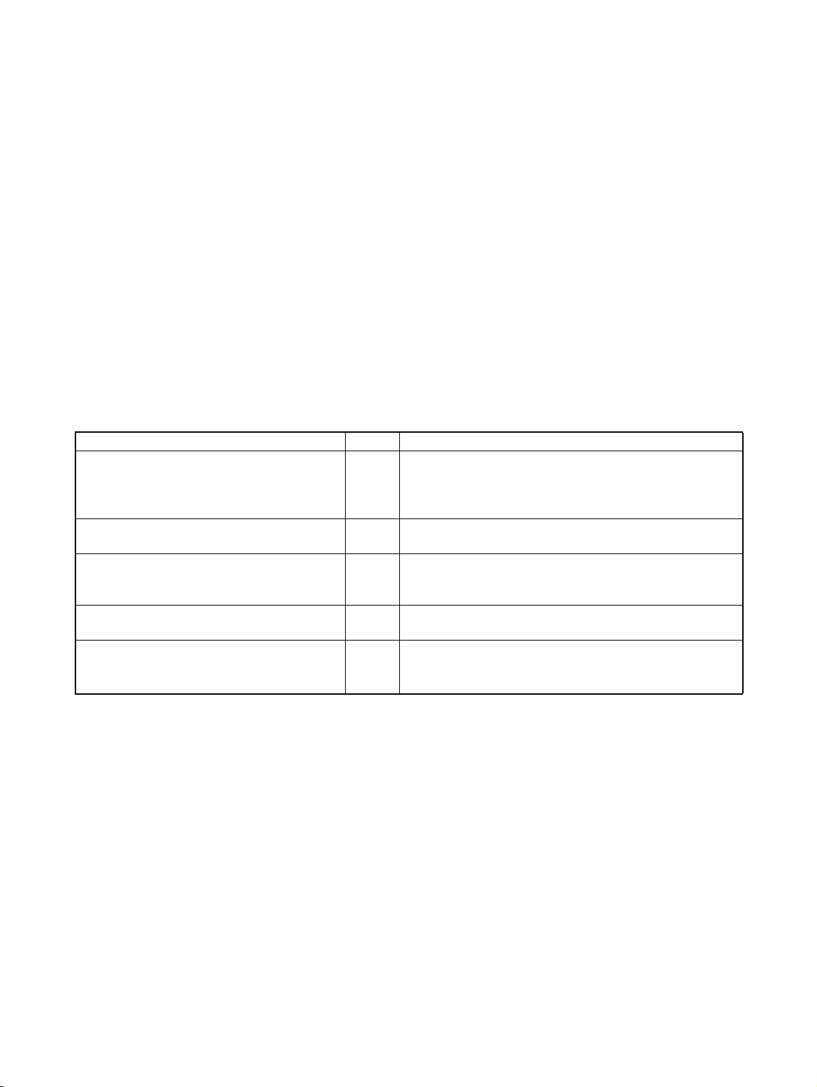
1-1-2 Function Block Specifications
For specifications that are not listed in the following table, refer to the CX-Programmer Operation Manual (W446).
Item Specifications
Model number WS02-CXPC1-E-V7
Setup disk CD-ROM
Compatible CPU Units (PLC models)
Note The function block and structured
text functions supported by CS/
CJ-series CPU Units with unit version 4.0 or later can not be used
in CS/CJ-series CPU Units with
unit version 3.0 or earlier, CPseries PLCs, NSJ-series PLCs, or
FQM1-series PLCs.
For details, refer to 1-6 Version
Upgrade Information.
CS/CJ-series CS1-H, CJ1-H, and CJ1M CPU Units with unit version 3.0 or later
are compatible.
Device Type CPU Type
• CJ2H CJ2H-CPU68/67/66/65/64/68-EIP/67-EIP/66-EIP/65-EIP
/64-EIP
• CS1G-H CS1G-CPU42H/43H/44H/45H
• CS1H-H CS1H-CPU63H/64H/65H/66H/67H
• CJ1G-H CJ1G-CPU42H/43H/44H/45H
• CJ1H-H CJ1H-CPU65H/66H/67H/64H-R/65H-R/66H-R/67H-R
• CJ1M CJ1M-CPU11/12/13/21/22/23
The following CP-series CPU Units are compatible.
• CP1H CP1H-X/XA/Y
• CP1L CP1L-M/L
Note If a user program containing function blocks created on the CX-Program-
mer Ver. 5.0 or later is downloaded to a CPU Unit that does not support
function blocks (CS/CJ-series CPU Units with unit version 2.0 or earlier),
all instances will be treated as illegal commands and it will not be possible to edit or execute the user program.
• NSJ G5D (Used for the NSJ5-TQ0@-G5D, NSJ5-SQ0@-G5D, NSJ8
-TV0@-G5D, NSJ10-TV0@-G5D, and NSJ12-TS0@-G5D)
M3D (Used for the NSJ5-TQ0@-M3D, NSJ5-SQ0@-M3D, and
NSJ8-TV0@-M3D)
• FQM1-CM FQM1-CM002
• FQM1-MMA FQM1-MMA22
• FQM1-MMP FQM1-MMP22
CS/CJ/CP Series Function Restrictions
• Instructions Not Supported in Function Block Definitions
Block Program Instructions (BPRG and BEND), Subroutine Instructions (SBS,
GSBS, RET, MCRO, and SBN), Jump Instructions (JMP, CJP, and CJPN),
Step Ladder Instructions (STEP and SNXT), Immediate Refresh Instructions
(!), I/O REFRESH (IORF), ONE-MS TIMER (TMHH and TMHHX) (These timers can be used with CJ1-H-R CPU Units.)
Note For details and other restrictions, refer to 2-4 Programming Restrictions.
5
Page 31

Introducing the Function Blocks Section 1-1
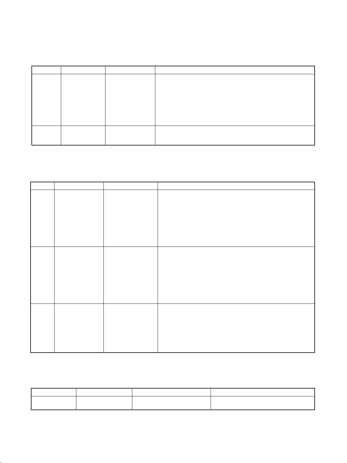
Item Specifications
Functions not
supported by
CX-Programmer Ver. 4.0
or earlier.
Defining
and creating function blocks
Number of
function
block definitions
Function
block
names
CJ2H Units:
• CJ2H-CPU6@(-EIP): 2,048 max. per CPU Unit
CS1-H/CJ1-H CPU Units:
• Suffix -CPU44H/45H/64H/65H/66H/67H/64H-R/65H-R/66H-R/67H-R: 1,024
max. per CPU Unit
• Suffix -CPU42H/43H/63H: 128 max. per CPU Unit
CJ1M CPU Units:
• CJ1M-CPU11/12/13/21/22/23: 128 max. per CPU Unit
CP1H CPU Units:
• All models: 128 max. per CPU Unit
CP1L CPU Units:
• CP1L-M/L: 128 max. per CPU Unit
NSJ Controllers:
•NSJ@-@@@@-G5D: 1,024 max. per Controller;
NSJ@-@@@@-M3D: 128 max. per Controller
FQM1 Flexible Motion Controllers:
• FQM1-CM002/MMA22/MMP22: 128 max. per Controller
64 characters max.
6
Page 32

Introducing the Function Blocks Section 1-1
Item Specifications
Functions not
supported by
CX-Programmer Ver. 4.0
or earlier.
Defining
and creating function blocks
Creating
instances
Storing
function
blocks as
files
Variables Variable names 30,000 characters max.
Variable types Input variables (Inputs), output variables (Out-
Number of variables used in
a function block
(not including internal variables, external variables,
EN, and EN0)
Allocation of addresses
used by variables
Actual address specification Supported
Array specifications Supported (one-dimensional arrays only and only
Language Function blocks can be created in ladder programming language or structured
text (ST, see note).
Number of
instances
CJ2H Units:
• CJ2H-CPU6@(-EIP): 2,048 max. per CPU Unit
CS1-H/CJ1-H CPU Units:
puts), input-output variables (In Out), internal
variables (Internals), and external variables
(Externals)
Maximum number of variables per function block
definition
• Input-output variables: 16 max.
• Input variables + input-output variables: 64 max.
• Output variables + input-output variables: 64
max.
Automatic allocation (The allocation range can be
set by the user.)
for internal variables and input-output variables)
• Suffix -CPU44H/45H/64H/65H/66H/67H/64H-R/65H-R/66H-R/67H-R: 2,048
max. per CPU Unit
• Suffix -CPU42H/43H/63H: 256 max. per CPU Unit
CJ1M CPU Units:
• CJ1M-CPU11/12/13/21/22/23: 256 max. per CPU Unit
CP1H CPU Units:
• All models: 256 max. per CPU Unit
CP1L CPU Units:
• CP1L-M/L: 256 max. per CPU Unit
NSJ Controllers:
•SJ@-@@@@-G5D: 2,048 max. per Controller;
NSJ@-@@@@-M3D: 256 max. per Controller
FQM1 Flexible Motion Controllers:
• FQM1-CM002/MMA22/MMP22: 256 max. per Controller
Instance
names
Project files The project file (.cxp/cxt) Includes function block definitions and instances.
Program
files
Function
block library
files
15,000 characters max.
The file memory program file (*.obj) includes function block definitions and
instances.
Each function block definition can be stored as a single file (.cxf) for reuse in
other projects.
Note The structured text (ST language) conforms to the IEC 61131-3 standard, but
CX-Programmer Ver. 5.0 supports only assignment statements, selection
statements (CASE and IF statements), iteration statements (FOR, WHILE,
REPEAT, and EXIT statements), RETURN statements, arithmetic operators,
logical operators, comparison functions, numeric functions, standard string
functions, numeric string functions, OMRON expansion functions, and comments. For details, refer to SECTION 5 Structured Text (ST) Language Speci-
fications in Part 2: Structured Text (ST).
7
Page 33

Introducing the Function Blocks Section 1-1
1-1-3 Files Created with CX-Programmer Ver. 6.0 or Later
Project Files (*.cxp) and
File Memory Program
Files (*.obj)
Function Block Library
Files (*.cxf)
Projects created using CX-Programmer that contain function block definitions
and projects with instances are saved in the same standard project files
(*.cxp) and file memory program files (*.obj).
The following diagram shows the contents of a project. The function block definitions are created at the same directory level as the program within the relevant PLC directory.
Project file (.cxp)
PLC1
PLC2
Global symbol table
I/O table
PLC Setup
PLC memory table
Program (with rung comments)
Local symbol table
Section 1 (with instances)
Section 2 (with instances)
END section (with instances)
Function block definitions
FunctionBlock1
FunctionBlock2
Instances created
in program
sections.
Each function block can be
stored in a separate
definition file (.cxf).
A function block definition created in a project with CX-Programmer Ver. 6.0
can be saved as a file (1 definition = 1 file), enabling definitions to be loaded
into other programs and reused.
Note When function blocks are nested, all of the nested (destination) function block
definitions are included in this function block library file (.cxf).
Project Text Files
Containing Function
Data equivalent to that in project files created with CX-Programmer Ver. 6.0
(*.cxp) can be saved as CXT text files (*.cxt).
Blocks (*.cxt)
1-1-4 Function Block Menus in CX-Programmer Ver. 5.0 (and later
Versions)
The following tables list menus related to function blocks in CX-Programmer
Ver. 5.0 and later versions. For details on all menus, refer to the CX-Program-
mer Operation Manual (W446).
Main Menu
Main
menu
File Function Block Load Function
Submenu Shortcut Function
--- Reads the saved function block library files (*.cxf).
Block from File
Save Function
Block to File
--- Saves the created function block definitions to a file ([func-
tion block library file]*.cxf).
8
Page 34

Introducing the Function Blocks Section 1-1
Main
menu
Edit Update Function Block --- When a function block definition’s input variables, output
To Lower Layer --- Jumps to the function block definition for the selected
Function Block (ladder) generation --- Generates a ladder-programmed function block for the
View Monitor FB Instance --- When monitoring the program online, monitors ST variable
To Lower Layer --- Displays on the right side the contents of the function block
To Upper Layer --- Returns to the calling instance (ladder diagram or ST).
Window FB Instance
Insert Function Block Invocation F Creates an instance in the program (section) at the present
Function Block Parameter P When the cursor is located to the left of an input variable or
PLC Memory
Allocation
Program Online Edit Begin --- Starts online editing of a function block.
Submenu Shortcut Function
variables, or input-output variables have been changed
after the instance was created, an error will be indicated by
displaying the instance’s left bus bar in red. This command
updates the instance with the new information and clears
the error.
instance.
selected program section while automatically determining
address application conditions.
status as well as I/O bit and word status (I/O bit monitor) of
the ladder diagram in the instance.
(Supported by CX-Programmer Ver. 6.1 and later only).
definition of the selected instance. (Supported by CX-Programmer Ver. 6.0 and later only.)
(Supported by CX-Programmer Ver. 6.0 and later only.)
--- Displays the FB Instance Viewer. (When nesting, the display shows details such as the relationship between
instance nesting levels and allocated variable addresses in
the instances.)
cursor location.
the right of an output variable, sets the variable’s input or
output parameter.
--- Sets the range of addresses (function block instance areas)
internally allocated to the selected instance’s variables.
--- Checks the status of the addresses internally allocated to
the selected instance’s variables.
--- Checks the addresses internally allocated to each variable
in the selected instance.
--- Optimizes the allocation of addresses internally allocated to
variables.
block.
online.
--- Transfers only the function block source.
--- Forcefully releases the access rights for function block,
SFC, and ST online editing held by another user.
Function
Block/
SFC
Memory
Viewer
Function Block
/SFC Memory
Allocation
Function Block
/SFC Memory
Statistics
Function Block
Instance
Address
Optimize Function Block/SFC
Memory
Send Change --- Transfers changes made during online editing of a function
Cancel --- Cancels changes made to a function block being edited
Transfer FB
Source
Release FB
Online Edit
Access Rights
9
Page 35

Introducing the Function Blocks Section 1-1
Main
menu
Tools Simulation Break Point |
Submenu Shortcut Function
Set/Clear
Break Point
Break Point |
Clear All Break
Point
Mode | Run
(Monitor Mode)
Mode | Stop
(Program
Mode)
Mode | Pause --- Pauses simulator operation.
Step Run --- Executes just one step of the simulator’s program.
Step Run |
Step In
Step Run |
Step Out
Step Run |
Continuous
Step Run
Step Run |
Scan Run
Always Display
Current Execution Point
Break Point List --- Displays a list of the break points that have been set.
--- Sets or clears a break point.
--- Clears all break points.
--- Executes continuous scanning. (Sets the ladder execution
engine’s run mode to MONITOR mode.)
--- Sets the simulator’s operation mode to PROGRAM mode.
--- When there is a function block call instruction, this command moves to execution of the internal program step.
--- When a function block’s internal program step is being executed, this command returns to the next higher level (call
source) and pauses execution.
--- Executes steps continuously for a fixed length of time.
--- Executes for one cycle and pauses execution.
--- Used with the Step Run or Continuous Step Run commands to automatically scroll the display and always show
the pause point.
(Operation can be jumped to a specified point.)
Main Pop-up Menus
Pop-up Menu for Function Block Definitions
Pop-up menu Function
Insert Function Block Ladder Creates a function block definition with a ladder programming language algo-
rithm.
Structured Text Creates a function block definition with an ST language algorithm.
From file Reads a function block definition from a function block library file (*.cxf).
Pop-up Menu for Inserted Function Blocks
Pop-up menu Function
Open Displays the contents of the selected function block definition on the right side
Save Function Block File Saves the selected function block definition in a file.
Compile Compiles the selected function block definition.
FB online Edit Begin Starts online editing of a function block.
Send Change Transfers changes made during online editing of a function block.
Cancel Cancels changes made to a function block being edited online.
Transfer FB Source Transfers only the function block source.
Release FB Online
Edit Access Rights
of the window.
Forcefully releases the access rights for function block online editing held by
another user.
10
Page 36

Function Blocks Section 1-2
Pop-up Menu for Function Block Variable Tables
Pop-up menu Function
Edit Edits the variable.
Insert Variable Adds a variable to the last line.
Insert Variable Above Inserts the variable above the current cursor position.
Below Inserts the variable below the current cursor position.
Cut Cuts the variable.
Copy Copies the variable.
Paste Pastes the variable.
Find Searches for the variable. Variable names, variable comments, or all (text strings) can
be searched.
Replace Replaces the variable.
Delete Deletes the variable.
Rename Changes only the name of the variable.
Pop-up Menu for Instances
Pop-up menu Function
Edit Changes the instance name.
Update Invocation When a function block definition’s input variables, output variables, or input-output vari-
ables have been changed after the instance was created, an error will be indicated by
displaying the instance’s left bus bar in red. This command updates the instance with
the new information and clears the error.
Monitor FB Ladder Instance When monitoring the program online, monitors I/O bit and word status (I/O bit monitor)
of the ladder diagram in the instance.
(Supported by CX-Programmer Ver. 6.0 and later only).
Monitor FB Instance When monitoring the program online, monitors ST variable status as well as I/O bit and
word status (I/O bit monitor) of the ladder diagram in the instance.
(Supported by CX-Programmer Ver. 6.1 and later only).
Register in Watch Window Displays the FB variables registration Dialog Box in order to register a variable from the
selected instance to the Watch Window.
Function Block Definition Displays the selected instance’s function block definition on the right side of the window.
Shortcut Keys
F Key: Pasting Function
Block Definitions in
Program
Enter Key: Inputting
Parameters
Move the cursor to the position at which to create the copied function block
instance in the Ladder Section Window, and press the F Key. This operation is
the same as selecting Insert - Function Block Invocation.
Position the cursor at the left of the input variable or input-output variable, or
at the right of the output variable and press the Enter Key. This operation is
the same as selecting Insert - Function Block Parameter.
1-2 Function Blocks
1-2-1 Outline
A function block is a basic program element containing a standard processing
function that has been defined in advance. Once the function block has been
defined, the user just has to insert the function block in the program and set
the I/O in order to use the function.
As a standard processing function, a function block does not contain actual
addresses, but variables. The user sets addresses or constants in those variables. These address or constants are called parameters. The addresses
used by the variables themselves are allocated automatically by the CX-Programmer for each program.
11
Page 37

Function Blocks Section 1-2
With the CX-Programmer, a single function block can be saved as a single file
and reused in other PLC programs, so standard processing functions can be
made into libraries.
Program 2
Copy of function block A
Function block A
Standard
program section
written with
variables
Define in advance.
Insert in
program.
Save function
block as a file.
Convert to
library function.
Function
block A
Reuse.
1-2-2 Advantages of Function Blocks
Function blocks allow complex programming units to be reused easily. Once
standard programming is created in a function block and saved in a file, it can
be reused just by placing the function block in a program and setting the
parameters for the function block’s I/O. The ability to reuse existing function
blocks will save significant time when creating/debugging programs, reduce
coding errors, and make the program easier to understand.
Program 1
Copy of function block A
Input Output
Variable Variable
Set
Copy of function block A
Input Output
Variable Variable
To another PLC program
Set
Variable
Output
Structured
Programming
Easy-to-read “Black Box”
Design
Structured programs created with function blocks have better design quality
and require less development time.
The I/O operands are displayed as variable names in the program, so the program is like a “black box” when entering or reading the program and no extra
time is wasted trying to understand the internal algorithm.
Use One Function Block
for Multiple Processes
Many different processes can be created easily from a single function block by
using the parameters in the standard process as input variables (such as
timer SVs, control constants, speed settings, and travel distances).
Reduce Coding Errors Coding mistakes can be reduced because blocks that have already been
debugged can be reused.
Black-boxing Know-how Read-protection can be set for function blocks to prevent programming know-
how from being disclosed.
Data Protection The variables in the function block cannot be accessed directly from the out-
side, so the data can be protected. (Data cannot be changed unintentionally.)
Improved Reusability with
Variable Programming
The function block’s I/O is entered as variables, so it isn’t necessary to change
data addresses in a block when reusing it.
Creating Libraries Processes that are independent and reusable (such as processes for individ-
ual steps, machinery, equipment, or control systems) can be saved as function block definitions and converted to library functions.
12
Page 38

Function Blocks Section 1-2
The function blocks are created with variable names that are not tied to actual
addresses, so new programs can be developed easily just by reading the definitions from the file and placing them in a new program.
Supports Nesting and
Multiple Languages
Mathematical expressions can be entered in structured text (ST) language.
With CX-Programmer Ver. 6.0 and later versions, function blocks can be
nested. The function block nesting function allows just special processing to
be performed in a ST-language function block nested within a ladder-language function block.
Function block (ladder language)
1-2-3 Function Block Structure
Function blocks consist of function block definitions that are created in
advance and function block instances that are inserted in the program.
Function Block
Definitions
Function block definitions are the programs contained in function blocks. Each
function block definition contains the algorithm and variable definitions, as
shown in the following diagram.
Call (Nesting)
Function block (ST language)
Number of Function Block
Definitions
Function Block Definition
Example: CLOCK PULSE
Algorithm
Variable definitions
Example: CLOCK PULSE
1. Algorithm
tim_b
tim_a
2. Variable Definitions
Usage
Internal
Internal
Input
Input
TIMX tim_a OFF_TIME
TIMX tim_b ON_TIME
Name
tim_a TIMER
tim_b TIMER
ON_TIME INT
OFF_TIME INT
ENO
Type
1. Algorithm
Standardized programming is written with variable names rather than real I/O
memory addresses. In the CX-Programmer, algorithms can be written in
either ladder programming or structured text.
2. Variable Definitions
The variable table lists each variable’s usage (input, output, input-output, or
internal) and properties (data type, etc.). For details, refer to 1-3 Variables.
The maximum number of function block definitions that can be created for one
CPU Unit is either 128 or 1,024 depending on the CPU Unit model.
13
Page 39

Function Blocks Section 1-2
Instances To use an actual function block definition in a program, create a copy of the
function block diagram and insert it in the program. Each function block definition that is inserted in the program is called an “instance” or “function block
instance.” Each instance is assigned an identifier called an “instance name.”
By generating instances, a single function block definition can be used to process different I/O data with the same function.
Not yet in program
and memory not yet
allocated
(abstract).
Function Block Definition FB1
1. Algorithm
Standard
program unit
with variable
names a, b, c,
etc.
2. Parameters
Table defining usage
and properties of
variables a, b, c, etc.
Insert in
program.
Insert in
program.
Block instance in program with memory
allocated. (object)
Program
Instance FB1_1 of function block definition FB1
Input
data
Instance FB1_2 of function block definition FB1
Input
data
Instance
ab
ab
c
Output data
Output data
c
Output data
Output data
Automatic
allocation
Automatic
allocation
Memory
used
Memory
for FB1_1
Memory
for FB1_2
Different I/O data
can be processed
with the same
function.
Note Instances are managed by names. More than one instance with the same
name can also be inserted in the program. If two or more instances have the
same name, they will use the same internal variables. Instances with different
names will have different internal variables.
For example, consider multiple function blocks that use a timer as an internal
variable. In this case all instances will have to be given different names. If
more than one instance uses the same name, the same timer would be used
in multiple locations, resulting in duplicated use of the timer.
If, however, internal variables are not used or they are used only temporarily
and initialized the next time an instance is executed, the same instance name
can be used to save memory.
instance_A
Function Block Definition
TIMER_FB
Variable Definitions
Internal variable: WORK_NUM
TIMER_FB
Use same internal variables.
instance_A
TIMER_FB
Use different internal variables.
instance_B
TIMER_FB
Number of Instances Multiple instances can be created from a single function block definition. Up to
either 256 or 2,048 instances can be created for a single CPU Unit depending
on the CPU Unit model. The allowed number of instances is not related to the
number of function block definitions and the number of tasks in which the
instances are inserted.
14
Page 40

Function Blocks Section 1-2
Parameters Each time an instance is created, set the real I/O memory addresses or con-
stants for input variables, output variables, and input-output variables used to
pass input data values to instances and obtain output data values from
instances. These addresses and constants are called parameters.
Instance of Function Block Definition A
Input 0.00
Input 3.00
Set the constants or
input source addresses
from which to pass data.
ab
c
Output 2.00
Set the constant or
output destination
address to which to pass
data.
Using Input Variables and Output Variables
With input variables and output variables, it is not the input source address
itself, but the contents at the input address in the form and size specified by
the variable data type that is passed to the function block. In a similar fashion,
it is not the output destination address itself, but the contents for the output
address in the form and size specified by the variable data type that is passed
from the function block.
Even if an input source address (i.e., an input parameter) or an output destination address (i.e., an output parameter) is a word address, the data that is
passed will be the data in the form and size specified by the variable data type
starting from the specified word address.
Program
Instance of Function Block Definition A
Input D100
mk
Output D300
Input D200
Examples:
If m is type WORD, one word of data from D100 will be passed to the
variable.
If n is type DWORD, two words of data from D200 and D201 will be
passed to the variable.
If k is type LWORD, four words of data from the variable will be passed
to the D300 to D303.
n
Note (1) Only addresses in the following areas can be used as parameters: CIO
Area, Auxiliary Area, DM Area, EM Area (banks 0 to C), Holding Area,
and Work Area.
The following cannot be used: Index and Data Registers (both direct and
indirect specifications) and indirect addresses to the DM Area and EM
Area (both in binary and BCD mode).
(2) Local and global symbols in the user program can also be specified as
parameters. To do so, however, the data size of the local or global symbol
must be the same as the data size of the function block variable.
(3) When an instance is executed, input values are passed from parameters
to input variables before the algorithm is processed. Output values are
15
Page 41

Function Blocks Section 1-2
passed from output variables to parameters just after processing the algorithm. If it is necessary to read or write a value within the execution cycle of the algorithm, do not pass the value to or from a parameter. Assign
the value to an internal variable and use an AT setting (specified addresses).
!Caution If an address is specified in an input parameter, the values in the address are
passed to the input variable. The actual address data itself cannot be passed.
!Caution Parameters cannot be used to read or write values within the execution cycle
of the algorithm. Use an internal variable with an AT setting (specified
addresses). Alternatively, reference a global symbol as an external variable.
Using Input-Output Variables (In Out)
When using an input-output variable, set the address for the input parameter.
A constant cannot be set. The address set for the input parameter will be
passed to the function block. If processing is performed inside the function
block using the input-output variable, the results will be written to I/O starting
at the address set for the size of the variable.
Program
Instance of function block definition A
Automatically set.
Input
D200 D200 a a
Address passed.
D200
D201
Processing is performed inside the function block using variable
“a.” The resulting value is written to I/O memory for the size of
variable “a” starting at address D200.
Variable “a”
Output
Address passed.
“a” changed by function
block processing.
Note Input-output variables are specified in a CX-Programmer variable table by
selecting “In Out” for the variable usage.
16
Page 42

Function Blocks Section 1-2
■ Reference Information
A variety of processes can be created easily from a single function block by
using parameter-like elements (such as fixed values) as input variables and
changing the values passed to the input variables for each instance.
Example: Creating 3 Instances from 1 Function Block Definition
Cyclic task 0
Instance
CASCADE_01
Algorithm
Internal and I/O
Function Block Definition
Example: CONTROL
Algorithm
Variables
Example:
There are 3 FB
instances and each
has its own I/O and
internal variables.
variables
Instance
CASCADE_02
Algorithm
Internal and I/O
variables
Instance
CASCADE_03
Algorithm
Internal and I/O
variables
If internal variables are not used, if processing will not be affected, or if the
internal variables are used in other locations, the same instance name can be
used at multiple locations in the program.
Cyclic task 0
P_On
The same instance can be
Function block definition
Example: CONTROL
Algorithm
Variables
used at multiple locations.
Instance
CASCADE
Algorithm
Internal and I/O
variables
P_On
P_On
&20
&10
P_On
&15
&10
Cyclic task 1
P_On
&7
&8
CASCADE
CONTROL
EN ENO
&100
PARA_1
&130
PARA_2
CASCADE
CONTROL
EN ENO
&50
PARA_1
&150
PARA_2
CASCADE_01
CONTROL
EN ENO
ON_TIME
OFF_TIME
CASCADE_02
CONTROL
EN ENO
ON_TIME
OFF_TIME
CASCADE_03
CONTROL
EN ENO
ON_TIME
OFF_TIME
1.0
1.1
1.2
1.0
1.1
Cyclic task 1
P_On
&100
&200
CASCADE
EN ENO
PARA_1
PARA_2
CONTROL
1.2
Some precautions are required when using the same memory area. For
example, if the same instance containing a timer instruction is used in more
than one program location, the same timer number will be used causing coil
duplication, and the timer will not function properly if both instructions are executed.
17
Page 43

Variables Section 1-3
Registration of Instances Each instance name is registered in the global symbol table as a file name.
Program
Instance (sample) of function block definition A
ab
c
The instance is registered in the
global symbol table with the instance
name as the symbol name.
Name
sample FB [FunctionBlock1] N/A[Auto]
Instance name
Data type
Address/
value
The function block definition
name is registered after FB in
square parentheses [ ].
1-3 Variables
1-3-1 Introduction
In a function block, the addresses (see note) are not entered as real I/O memory addresses, they are all entered as variable names. Each time an instance
is created, the actual addresses used by the variable are allocated automatically in the specified I/O memory areas by the CX-Programmer. Consequently, it isn’t necessary for the user to know the real I/O memory addresses
used in the function block, just as it isn’t necessary to know the actual memory allocations in a computer. A function block differs from a subroutine in this
respect, i.e., the function block uses variables and the addresses are like
“black boxes.”
Example:
Insert in
program.
Program
Instance of function block definition A
Input 0.00
Input 3.00
ab
c
Output 2.00
Function block definition A
Standard program section with
variable names a, b, c, etc.
a
c
b
MOV
Specify inputs and outputs
at the same time.
18
Table indicating usage and
properties of variables a, b, c, etc.
Usage: Inputs
Properties:
Name Type AT Initial Value Retained
a BOOL
c BOOL
Usage: Outputs
Properties:
Name Type AT Initial Value Retained
BOOL
b
Status of 0.00 (1 or 0) is
passed to a.
0.00 a
1 1
Status of 3.00 (1 or 0) is
passed to c.
3.00 c
0 0
The system automatically allocates the
addresses used by variables a, b, and c. For
example, when W100 to W120 is set as the
system’s non-retained memory area, bit
Status of b (1 or 0) is
passed to 2.00.
2.00b
11
addresses such as a = W10000, b = W10001,
and c = W10002 will be allocated.
Note Constants are not registered as variables. Enter constants directly in instruc-
tion operands.
Page 44

Variables Section 1-3
• Ladder programming language: Enter hexadecimal numerical values
after the # and decimal values after the &.
• Structured text (ST language): Enter hexadecimal numerical values after 16# and enter decimal numerical values as is.
Exception: Enter directly or indirectly specified addresses for Index Registers
IR0 to IR15 and Data Registers DR0 to DR15 directly into the instruction
operand.
1-3-2 Variable Usage and Properties
Variable Usage The following variable types (usages) are supported.
Internals: Internal variables are used only within an instance. They cannot
be used pass data directly to or from I/O parameters.
Inputs: Input variables can input data from input parameters outside of
the instance. The default input variable is an EN (Enable) variable, which passes input condition data.
Outputs: Output variables can output data to output parameters outside of
the instance. The default output variable is an ENO (Enable Out)
variable, which passes the instance’s execution status.
In Out: Input-output variables can input data from input parameters out-
side of the instance and can return the results of processing in a
function block instance to external parameters.
Externals: External variables are either system-defined variables registered
in advance with the CX-Programmer, such as the Condition Flags
and some Auxiliary Area bits, or user-defined global symbols for
use within instances.
For details on variable usage, refer to the section on Variable Type (Usage)
under Variable Definitions in 2-1-2 Function Block Elements.
The following table shows the number of variables that can be used and the
kind of variable that is created by default for each of the variable usages.
1-3-3 Variable Properties
Variables have the following properties.
Variable Name The variable name is used to identify the variable in the function block. It
doesn’t matter if the same name is used in other function blocks.
Note The variable name can be up to 30,000 characters long, but must not begin
with a number. Also, the name cannot contain two underscore characters in a
row. The character string cannot be the same as that of a an index register
such as in IR0 to IR15. For details on other restrictions, refer to Variable D e f i-
nitions in 2-1-2 Function Block Elements.
Data Type Select one of the following data types for the variable:
BOOL, INT, UINT, DINT, UDINT, LINT, ULINT, WORD, DWORD, LWORD,
REAL, LREAL, TIMER, COUNTER, and STRING
For details on variable data types, refer to Variable Definitions in 2-1-2 Func-
tion Block Elements.
AT Settings (Allocation to
an Actual Addresses)
It is possible to set a variable to a particular I/O memory address rather than
having it allocated automatically by the system. To specify a particular
address, the user can input the desired I/O memory address in this property.
This property can be set for internal variables only. Even if a specific address
is set, the variable name must still be used in the algorithm.
19
Page 45

Variables Section 1-3
Refer to Variable Definitions in 2-1-2 Function Block Elements for details on
AT settings and 2-5-3 AT Settings for Internal Variables for details on using AT
settings.
Array Settings A variable can be treated as a single array of data with the same properties.
To convert a variable to an array, specify that it is an array and specify the
maximum number of elements.
This property can be set for internal variables and input-output variables only.
Only one-dimensional arrays are supported by the CX-Programmer Ver. 5.0
and later versions.
• Setting Procedure
Click the Advanced Button, select the Array Variable option, and input the
maximum number of elements.
• When entering an array variable name in the algorithm in a function block
definition, enter the array index number in square brackets after the variable number.
For details on array settings, refer to Variable Definitions in
Block Elements
.
Initial Value This is the initial value set in a variable before the instance is executed for the
first time. Afterwards, the value may be changed as the instance is executed.
For example, set a boolean (BOOL) variable (bit) to either 1 (TRUE) or 0
(FALSE). Set a WORD variable to a value between 0 and 65,535 (between
0000 and FFFF hex).
If an initial value is not set, the variable will be set to 0. For example, a boolean variable would be 0 (FALSE) and a WORD variable would be 0000 hex.
2-1-2 Function
Retain Select the Retain Option if you want a variable’s data to be retained when the
PLC is turned ON again and when the PLC starts operating.
• Setting Procedure
Select the Retain Option.
Size When a STRING variable is used, the size required to store the text string can
be set to between 1 and 255 characters.
1-3-4 Variable Properties and Variable Usage
The following table shows which properties must be set, can be set, and cannot be set, based on the variable usage.
Property Variable usage
Internals Inputs Outputs In Out
Name Must be set. Must be set. Must be set. Must be set.
Data Type Must be set. Must be set. Must be set. Must be set.
AT (specified
address)
Array specification Must be set. Cannot be set. Cannot be set. Must be set.
Initial Value Can be set. Cannot be set.
Retained Can be set. Cannot be set.
Size Can be set.
Can be set. Cannot be set. Cannot be set. Cannot be set.
Can be set. Cannot be set.
(See note 1.)
Can be set. Cannot be set.
(See note 1.)
Cannot be set. Cannot be set. Cannot be set.
(See note 2.)
20
(1) The value of the input parameter will be given.
(2) Valid only for STRING variables.
Page 46

Variables Section 1-3
1-3-5 Internal Allocation of Variable Addresses
When an instance is created from a function block definition, the CX-Programmer internally allocates addresses to the variables. Addresses are allocated
to all of the variables registered in the function block definition except for variables that have been assigned actual addresses with the AT S et ti ng s property.
Setting Internal Allocation
Areas for Variables
Program
Instance of function block definition A
Input 0.00
Note: Variable c is an internal
a
variable, so it is not displayed.
Usage: Inputs
Properties:
Name Type AT Initial Value
a BOOL
Usage: Outputs
Properties:
Name Type AT
b
BOOL
t
TIMER
Usage: Internals
Properties:
Name Type Initial Value
2000.00
c
BOOL
AT
Initial Value
b
Output 2.00
t
Output 5.00
Retained
Retained
YES
Retained
Non-retained area
Starting address
Retained area
Starting address
Timer area
Starting address
Counter area
Automatic allocation of
addresses by system
Manual allocation of address to
variable in FB by AT Settings option.
FB instance areas
Starting
address
Example
2000.00
15 0
CIO, H, W,
D, or E Area
15 0
H, D, or E
Area
T Area
C Area
Size (words)
Size (words)
Size (Completion
Flags)
Size (Completion
Flags)
The user sets the function block instance areas in which addresses are allocated internally by the system. The variables are allocated automatically by
the system to the appropriate instance area set by the user.
Setting Procedure
Select Function Block/SFC Memory - Function Block/SFC Memory Allocation from the PLC Menu. Set the areas in the Function Block/SFC Memory
Allocation Dialog Box.
21
Page 47
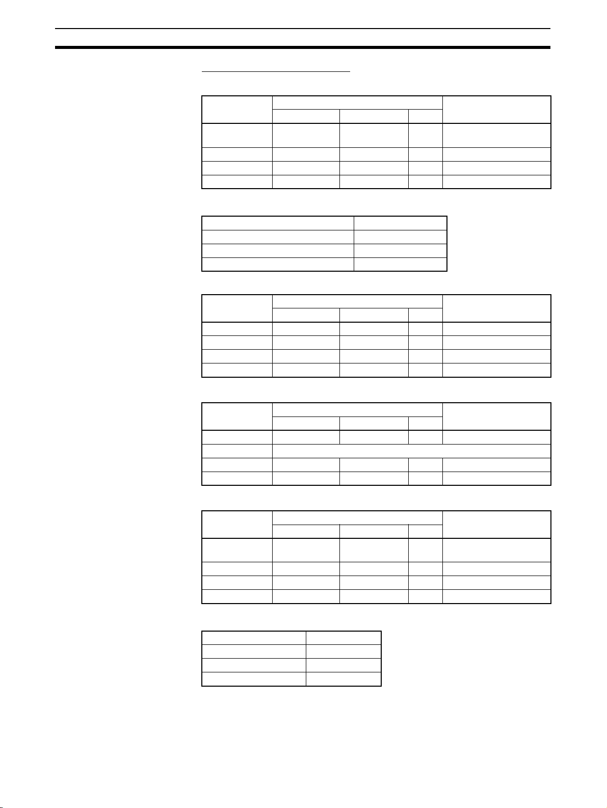
Variables Section 1-3
Function Block Instance Areas
CJ2-series CPU Units
FB Instance
Area
Non Retain H512 H1407 896 CIO, WR, HR, DM,
Retain H1408 H1535 128 HR, DM, EM (See note.)
Timers T3072 T4095 1024 TIM
Counters C3072 C4095 1024 CNT
Start address End address Size
Note Force-setting/resetting is enabled when the following EM banks are specified:
CJ2H-CPU64(-EIP)/-CPU65(-EIP) EM bank 3
CJ2H-CPU66(-EIP) EM banks 6 to 9
CJ2H-CPU67(-EIP) EM banks 7 to E
CJ2H-CPU68(-EIP) EM banks 11 to 18
CS/CJ-series CPU Units Ver. 3.0 or Later, and NSJ Controllers
FB Instance
Area
Non Retain H512 H1407 896 CIO, WR, HR, DM, EM
Retain H1408 H1535 128 HR, DM, EM
Timers T3072 T4095 1024 TIM
Counters C3072 C4095 1024 CNT
Start address End address Size
Default value Applicable memory
areas
EM (See note.)
Default value Applicable memory
areas
FQM1 Flexible Motion Controllers
FB Instance
Area
Non Retain 5000 5999 1000 CIO, WR, DM
Retain None
Timers T206 T255 50 TIM
Counters C206 C255 50 CNT
Start address End address Size
CP-series CPU Units
FB Instance
Area
Non Retain H512 H1407 896 CIO, WR, HR, DM (See
Retain H1408 H1535 128 HR, DM (See note.)
Timers T3072 T4095 1024 TIM
Counters C3072 C4095 1024 CNT
Start address End address Size
Note DM area of CP1L-L
Address CP1L-L
D0000 to D9999 Provided
D10000 to D31999 Not Provided
D32000 to D32767 Provided
Default value Applicable memory
areas
Default value Applicable memory
areas
note.)
22
Page 48

Converting Function Block Definitions to Library Files Section 1-4
Function Block Holding
Area Words (H512 to
H1535)
The Function Block Holding Area words are allocated from H512 to H1535.
These words are different to the standard Holding Area used for programs
(H000 to H511) and are used only for the function block instance area (internally allocated variable area). These words cannot be specified as instruction
operands. They are displayed in red if input when a function block is not being
created. Although the words can be input when creating a function block, an
error will occur when the program is checked. If this area is specified not to be
retained in the Function Block Memory Allocation Dialog Box, turn the power
ON/OFF or clear the area without retaining the values when starting operation.
1-4 Converting Function Block Definitions to Library Files
A function block definition created using the CX-Programmer can be stored as
a single file known as a function block definition file with filename extension
*.cxf. These files can be reused in other projects (PLCs).
Project Project
Function block definition
Example: CLOCK_PULSE
1. Algorithm
tim_b
TIMX tim_a OFF_TIME
tim_a
TIMX tim_b ON_TIME
ENO
2. Variable Definitions
Usage
Name
Internal
tim_a TIMER
tim_b TIMER
Internal
ON_TIME INT
Input
OFF_TIME INT
Input
Save
Type
Function block
definition file (.cxf)
Read
Function block definition
Example: CLOCK_PULSE
1. Algorithm
tim_b
TIMX tim_a OFF_TIME
tim_a
TIMX tim_b ON_TIME
ENO
2. Variable Definitions
Usage
Name
Internal
Internal
Input
Input
tim_a TIMER
tim_b TIMER
ON_TIME INT
OFF_TIME INT
Type
1-5 Usage Procedures
Once a function block definition has been created and an instance of the algorithm has been created, the instance is used by calling it when it is time to
execute it. Also, the function block definition that was created can be saved in
a file so that it can be reused in other projects (PLCs).
1-5-1 Creating Function Blocks and Executing Instances
The following procedure outlines the steps required to create and execute a
function block.
1,2,3... 1. First, create the function block definition including the algorithm and vari-
able definitions in ladder program or ST language. Alternatively, insert a
function block library file that has been prepared in advance.
Note (a) Create the algorithm entirely with variable names.
(b) When entering the algorithm in ladder programming language,
project files created with versions of CX-Programmer earlier than
Ver. 5.0 can be reused by reading the project file into CX-Programmer Ver. 5.0 or higher and copying and pasting useful parts.
(c) Existing ladder programming can be automatically turned into a
function block using Edit - Function Block (ladder) generation.
2. When creating the program, insert copies of the completed function block
definition. This step creates instances of the function block.
3. Enter an instance name for each instance.
23
Page 49

Usage Procedures Section 1-5
4. Set the variables’ input source addresses and/or constants and output
destination addresses and/or constants as the parameters to pass data for
each instance.
5. Select the created instance, select Function Block Memory - Function
Block Memory Allocation from the PLC Menu, and set the internal data
area for each type of variable.
6. Transfer the program to the CPU Unit.
7. Start program execution in the CPU Unit and the instance will be called and
executed if their input conditions are ON.
The instance is
Function block definition A
1. Algorithm
Standard
program section
with variable
names a, b, c,
etc.
2. Variables
Table defining usage
and properties of
variables a, b, c, etc.
Insert in
program.
Program
Input
condition
executed if the input
condition is established.
Instance of function block definition A
Input 0.00
a b
4. Specify the input source and
output destination addresses.
3. Input instance name
5. The system automatically allocates
the addresses used by these
variables. Set the data area area in
which these addresses are allocated.
Output 2.00
c
Output 3.00
1-5-2 Reusing Function Blocks
Use the following procedure to save a function block definition as a file and
use it in a program for another PLCs.
1,2,3... 1. Select the function block that you want to save and save it as a function
block definition file (*.cxf).
2. Open the other PLC’s project and open/read the function block definition
file (*.cxf) that was saved.
3. Insert the function block definition in the program when creating the new
program.
Function block definition A
Read and
insert.
Program
Input
condition
Input 1.00
Instance of function block definition A
c
Output 5.00
Output 6.00
ab
1. Algorithm
Standard
program section
with variable
names a, b, c,
etc.
2. Variables
Table defining usage
and properties of
variables a, b, c, etc.
Save
Function
block
definition
A
Function block
definition file (*.cxf)
Note In the CX-Programmer Ver. 5.0, each function block definition can be com-
piled and checked as a program. We recommend compiling to perform a program check on each function block definition file before saving or reusing the
file.
24
Page 50

Version Upgrade Information Section 1-6
1-6 Version Upgrade Information
Refer to the CX-Programmer Operation Manual (W446) for information on
upgraded functions other than those for function blocks and structure text.
Version 8.0 to 8.1 Upgrade Information
The new PLC models of CJ2H-CPU6@ supporting function blocks and structured text are now supported.
Version 7.2 to 8.0 Upgrade Information
The new PLC models of CJ2H-CPU6@-EIP supporting function blocks and
structured text are now supported.
Version 7.0 to 7.2 Upgrade Information
Improved Support for
Function Blocks and
For details on the other improvements to CX-Programmer functions in this
upgrade, refer to the CX-Programmer Operation Manual (W446).
Structured Text
■ IEC61131-3 Language Improvements
Support has been improved for the structured text and SFC languages, which
are IEC61131-3 languages. Ladder, structured text (ST), and SFC programming can be combined freely, so that the best language for each process can
be used, which reduces program development time and makes the program
easier to understand.
Support for ST Language in the Program (Task Allocation)
Version 7.0 Version 7.2
The ST language could be used only in function
blocks.
The ST language can be used in programs (task allocation) other than
function blocks. (ST programs can be allocated to tasks.)
Other programming languages can be combined freely in a single user
program. With this capability, numerical calculations can be written as
ST programs, and other processing can be written as ladder or SFC
programs.
Note Structured text is supported only by CS/CJ-series CPU Units with
unit version 4.0 or later. It is not supported by CP-series CPU
Units.
Comparison of Function Block Definitions and ST Programs
Version 7.0 Version 7.2
Function block definitions could not be compared.
• Function block definitions can be compared. With this capability, it is
easy to check for differences in function block definitions in programs.
• ST programs can also be compared.
25
Page 51

Version Upgrade Information Section 1-6
Version 6.1 to 7.0 Upgrade Information
Convenient Functions to Convert Ladder Diagrams to Function Blocks
Version 6.1 Version 7.0
Ladder programming can be copied into a function block definition to create a function block.
The symbols and addresses in the ladder programming, however, have to be checked and
input variables, internal variables, and output
variables have to be identified and manually registered.
Online Function Block Editing
Version 6.1 Version 7.0
Function block definitions (i.e., the algorithms
and variable tables) cannot be changed online
when the PLC is running. (Only I/O parameters
for function block instances can be changed.)
Support for STRING Data Type and Processing Functions in Standard Text Programs
Version 6.1 Version 7.0
• The STRING data type (text) cannot be used in
ST programming. (See note.)
• There are no text processing functions supported for ST programming.
• Even in a ladder program, the user has to consider the ASCII code and code size of text for
display messages and no-protocol communications (see note) when executing string processing instructions, data conversion instructions,
and serial communications instructions.
Note The user can use the PLC memory func-
tion of the CX-Programmer to input text
strings in I/O memory. The data size in I/O
memory, however, must be considered.
One or more program sections can be selected from the program and
then Function Block (ladder) generation selected from the menu to
automatically create a function block definition and automatically allocate variables according to symbols and addresses in the program sections. (Allocations can later be changed as required.) This enables
legacy programming to be easily converted to function blocks.
The algorithms and variables tables for function blocks can be changed
while the PLC is operation. (See note.) This enables debugging and
changing function block definitions in systems that cannot be stopped,
such as systems that operate 24 hours a day.
Operation: Right-click the function block definition in the Work Space
and select FB Online Edit - Begin from the pop-up menu.
Note Function block instances cannot be added.
Note This function cannot be used for simulations on CX-Simulator.
• The STRING data type (text) can be used in ST programming. This
enables, for example, substituting a text string for a variable (e.g., a :=
'@READ';) to easily set a variable containing text (i.e., ASCII characters). In doing this, the user does not have to be concerned with the
ASCII code or code size.
• Text processing functions are supported for ST programming, including text extraction, concatenation, and searching. This enables easily
processing text strings and display messages in ST programming
inside function blocks.
• Functions are also supported for sending and receiving text strings.
This enables easily processing no-protocol communications using ST
programming in functions blocks without being concerned with ASCII
codes.
Support for Input-Output Variables
Version 6.1 Version 7.0
• Input-output variables cannot be used in function blocks. (Only input variables, internal variables, and output variables can be used.)
• Arrays cannot be specified for input variables.
• Values are passed from input parameters to
input variables.
26
• Input-output variables can be used in function blocks.
• Input-output variables can be specified as arrays.
• Addresses are passed from input parameters to input variables
instead of values. This enables using input-output variable arrays
inside function blocks to enable easily passing large amounts of data
to function blocks using the input parameters.
Page 52

Version Upgrade Information Section 1-6
Version 6.0 to 6.1 Upgrade Information
Support for NSJ-series
NSJ Controllers
Support for FQM1 Unit
Version 3.0
The PLC model (“device type”) can be set to “NSJ” and the CPU type can be
set to the G5D.
The new models of the FQM1 Flexible Motion Controller are now supported
(i.e., the FQM1-CM002 Coordinator Module and the FQM1-MMA22/MMP22
Motion Control Modules).
Instance ST/Ladder Program Simulation Function
Previous version (Ver. 6.0) New version (Ver. 6.1)
The CX-Simulator could be used to execute a
ladder program step (Step Run), execute steps
continuously (Continuous Step Run), execute a
single cycle (Scan Run), and set I/O break point
conditions.
The Step Run, Continuous Step Run, Scan Run, and Set/Clear Break
Point functions can be executed as CX-Programmer functions.
All of these functions can be used with ladder programs and ladder/ST
programs in function blocks.
Note The CX-Simulator Ver. 1.6 (sold separately) must be installed in
order to use these functions.
Note I/O break conditions cannot be set.
Improved Function Block Functions
Monitoring ST Programs in Function Blocks
Previous version (Ver. 6.0) New version (Ver. 6.1)
The operation of ST programs within function
block instances could not be monitored while
monitoring the program online.
(It was possible to check the contents of a function block definition’s program and monitor the I/
O status of a function block instance’s ladder
diagram.)
The status of a function block instance’s ST program can be monitored
while monitoring the program.
To monitor the ST program’s status, either double-click the function
block instance or right-click the instance and select Monitor FB
Instance from the pop-up menu. At this point, it will be possible to
change PVs and force-set/reset bits.
Note Online editing is not supported.
Password Protection of Function Blocks
Previous version (Ver. 6.0) New version (Ver. 6.1)
The function block properties could be set to
prevent the display of a function block definition’s program.
The following two kinds of password protection can be set.
• Password protection restricting both reading and writing.
• Password protection restricting writing only.
27
Page 53

Version Upgrade Information Section 1-6
Version 5.0 to 6.0 Upgrade Information
Nesting Function Blocks
Previous version (Ver. 5.0) New version (Ver. 6.0)
A function block could not be called from another
function block. (Nesting not supported.)
I/O Bit Monitor Support for Ladder Programs in Function Blocks
Previous version (Ver. 5.0) New version (Ver. 6.0)
The I/O status of a function block instance’s ladder diagram could not be monitored while monitoring the program online.
(It was only possible to check the program in the
function block definition.)
A function block can be called from another function block (nested). Up
to 8 nesting levels are supported.
The languages of the calling function block and called function block
can be either ladder language or ST language.
The nesting level relationship between function blocks can be displayed
in a directory tree format. When function blocks are nested, just one
Function Block Library file (.cxf extension) is stored for the calling function block and its called (nested) function block definitions.
The I/O status of a function block instance’s ladder diagram can be
monitored while monitoring the program online.
To monitor the I/O status, either double-click the function block instance
or right-click the instance and select Monitor FB Ladder Instance
from the pop-up menu. At this point, it will be possible to monitor the
status of I/O bits and the content of words, change PVs, force-set/reset
bits, and monitor differentiation (ON/OFF transitions) of bits.
Note Online editing is not supported and timer/counter SVs cannot be
changed.
Registering and Monitoring Function Block Instance Variables in a Watch Window
Previous version (Ver. 5.0) New version (Ver. 6.0)
To register a function block instance’s variable in
a Watch Window, it was necessary to display the
Watch Window, double-click the window, and
select the desired variable from a pull-down list.
Multiple variables in a function block instance can be easily registered
together in the Watch Window. The FB variables registration Dialog Box
can be displayed with any of the following methods and the variables
can be registered together in that Dialog Box.
• Right-click the function block instance and select Register in Watch
Window from the pop-up menu.
• Select the desired function block instance in the program or variable
table and either copy/paste or drag/drop the instance into the Watch
Window.
• Move the cursor to an empty line in the Watch Window and select
Register in Watch Window from the pop-up menu.
Other Function Block Improvements
• The cross-reference pop-up function is supported in ladder programs
within function blocks.
• The ST language help program can be started from the pop-up menu in
ST Editor.
• A function block’s definitions can be opened just by double-clicking the
function block instance.
• The cursor automatically moves down after a function block instance’s
parameter input is confirmed.
28
Page 54

SECTION 2
Function Block Specifications
This section provides specifications for reference when using function blocks, including specifications on function blocks,
instances, and compatible PLCs, as well as usage precautions and guidelines.
2-1 Function Block Specifications . . . . . . . . . . . . . . . . . . . . . . . . . . . . . . . . . . . . 30
2-1-1 Function Block Specifications . . . . . . . . . . . . . . . . . . . . . . . . . . . . . 30
2-1-2 Function Block Elements . . . . . . . . . . . . . . . . . . . . . . . . . . . . . . . . . 31
2-2 Data Types Supported in Function Blocks . . . . . . . . . . . . . . . . . . . . . . . . . . . 41
2-2-1 Basic Data Types . . . . . . . . . . . . . . . . . . . . . . . . . . . . . . . . . . . . . . . 41
2-2-2 Derivative Data Types. . . . . . . . . . . . . . . . . . . . . . . . . . . . . . . . . . . . 41
2-3 Instance Specifications . . . . . . . . . . . . . . . . . . . . . . . . . . . . . . . . . . . . . . . . . . 42
2-3-1 Composition of an Instance . . . . . . . . . . . . . . . . . . . . . . . . . . . . . . . 42
2-3-2 Parameter Specifications. . . . . . . . . . . . . . . . . . . . . . . . . . . . . . . . . . 47
2-3-3 Operating Specifications. . . . . . . . . . . . . . . . . . . . . . . . . . . . . . . . . . 49
2-4 Programming Restrictions. . . . . . . . . . . . . . . . . . . . . . . . . . . . . . . . . . . . . . . . 51
2-4-1 Ladder Programming Restrictions . . . . . . . . . . . . . . . . . . . . . . . . . . 51
2-4-2 ST Programming Restrictions. . . . . . . . . . . . . . . . . . . . . . . . . . . . . . 53
2-4-3 Programming Restrictions . . . . . . . . . . . . . . . . . . . . . . . . . . . . . . . . 54
2-5 Function Block Applications Guidelines . . . . . . . . . . . . . . . . . . . . . . . . . . . . 56
2-5-1 Deciding on Variable Data Types . . . . . . . . . . . . . . . . . . . . . . . . . . . 56
2-5-2 Determining Variable Types
(Inputs, Outputs, In Out, Externals, and Internals). . . . . . . . . . . . . . 57
2-5-3 AT Settings for Internal Variables. . . . . . . . . . . . . . . . . . . . . . . . . . . 59
2-5-4 Array Settings for Input-Output Variables and Internal Variables . . 59
2-5-5 Specifying Addresses Allocated to Special I/O Units . . . . . . . . . . . 61
2-5-6 Using Index Registers. . . . . . . . . . . . . . . . . . . . . . . . . . . . . . . . . . . . 62
2-6 Precautions for Instructions with Operands Specifying the First
or Last of Multiple Words . . . . . . . . . . . . . . . . . . . . . . . . . . . . . . . . . . . . . . . . 65
2-7 Instruction Support and Operand Restrictions . . . . . . . . . . . . . . . . . . . . . . . . 68
2-8 CPU Unit Function Block Specifications . . . . . . . . . . . . . . . . . . . . . . . . . . . . 70
2-8-1 Specifications . . . . . . . . . . . . . . . . . . . . . . . . . . . . . . . . . . . . . . . . . . 70
2-8-2 Operation of Timer Instructions . . . . . . . . . . . . . . . . . . . . . . . . . . . . 75
2-9 Number of Function Block Program Steps and Instance Execution Time . . . 76
2-9-1 Number of Function Block Program Steps. . . . . . . . . . . . . . . . . . . . 76
2-9-2 Function Block Instance Execution Time. . . . . . . . . . . . . . . . . . . . . 77
29
Page 55

Function Block Specifications
2-1 Function Block Specifications
2-1-1 Function Block Specifications
Item Description
Number of function
block definitions
Number of instances CJ2H Units:
Number of instance
nesting levels
Number of variables
used in a function block
(not including internal
variables, external variables, EN, and EN0)
CJ2H Units:
• CJ2H-CPU6@(-EIP): 2,048 max. per CPU Unit
CS1-H/CJ1-H CPU Units:
• Suffix -CPU44H/45H/64H/65H/66H/67H/64H-R/65H-R/
66H-R/67H-R: 1,024 max. per CPU Unit
• Suffix -CPU42H/43H/63H: 128 max. per CPU Unit
CJ1M CPU Units:
• CJ1M-CPU11/12/13/21/22/23: 128 max. per CPU Unit
CP1H CPU Units:
• CP1H-XA/X/Y: 128 max. per CPU Unit
CP1L CPU Units:
• CP1L-M/L: 128 max. per CPU Unit
NSJ Controllers:
• All models: 1,024 max. per Controller
FQM1 Flexible Motion Controllers:
• FQM1-CM002/MMA22/MMP22: 128 max. per Controller
• CJ2H-CPU6@(-EIP): 2,048 max. per CPU Unit
CS1-H/CJ1-H CPU Units:
• Suffix -CPU44H/45H/64H/65H/66H/67H/64H-R/65H-R/
66H-R/67H-R: 2,048 max. per CPU Unit
• Suffix -CPU42H/43H/63H: 256 max. per CPU Unit
CJ1M CPU Units:
• CJ1M-CPU11/12/13/21/22/23: 256 max. per CPU Unit
CP1H CPU Units:
• CP1H-XA/X/Y: 256 max. per CPU Unit
CP1L CPU Units:
• CP1L-M/L: 256 max. per CPU Unit
NSJ Controllers:
• All models: 2,048 max. per Controller
FQM1 Flexible Motion Controllers:
• FQM1-CM002/MMA22/MMP22: 256 max. per Controller
• CX-Programmer Ver. 5.0:
Nesting is not supported.
• CX-Programmer Ver. 6.0 and later versions:
Supports nesting up to 8 levels. (The instance called from
the program is counted as one nesting level.)
Maximum number of variables per function block definition
• Input-output variables: 16 max.
• Input variables + input-output variables: 64 max.
• Output variables + input-output variables: 64 max.
Section 2-1
30
Page 56

Function Block Specifications
2-1-2 Function Block Elements
The following table shows the items that must be entered by the user when
defining function blocks.
Item Description
Function block
definition name
Language The programming language used in the function block defini-
Variable definitions Variable settings, such as operands and return values,
Algorithm Enter the programming logic in ladder or structured text.
Comment Function blocks can have comments.
Section 2-1
The name of the function block definition
tion. Select ladder programming or structured text
required when the function block is executed
• Type (usage) of the variable
• Name of the variable
• Data type of the variable
• Initial value of the variable
• Enter the programming logic using variables.
• Input constants directly without registering in variables.
Function Block
Definition Name
Each function block definition has a name. The names can be up to 64 characters long and there are no prohibited characters. The default function block
name is FunctionBlock@, where @ is a number (assigned in order).
Function block definition name
CLOCK PULSE
EN ENO
(BOOL) (BOOL)
ON_TIME
(INT)
OFF_TIME
(INT)
Language Select either ladder programming language or structured text (ST language).
Note (1) For details on ST language, refer to SECTION 5 Structured Text (ST)
Language Specifications in Part 2: Structured Text (ST).
(2) When nesting, function blocks using ST language and ladder language
can be combined freely (version 6.0 and higher only).
Variable Definitions Define the operands and variables used in the function block definition.
Variable Names • Variable names can be up to 30,000 characters long.
• Variables name cannot contain spaces or any of the following characters:
!“ #$%&‘()=-~^\|‘@{[+;*:}]<,>.?/
• Variable names cannot start with a number (0 to 9).
• Variable names cannot contain two underscore characters in a row.
•
The following characters cannot be used to indicate addresses in I/O
memory.
A, W, H (or HR), D (or DM), E (or EM), T (or TIM), C (or CNT) followed
by the numeric value (word address)
31
Page 57

Function Block Specifications
Variable Notation
Section 2-1
CLOCK PULSE
EN
ENO
(BOOL) (BOOL)
ON_TIME
(INT)
OFF_TIME
(INT)
Input variables
Output variables
Variable table
Usage
Name
tim_a TIMER
Internal
Internal
tim_b TIMER
ON_TIME INT
Input
OFF_TIME INT
Input
tim_b
tim_a
Internal
variables
Type
TIMX tim_a OFF_TIME
TIMX tim_b OFF_TIME
ENO
Variable Type (Usage)
Item Variable type
Inputs Outputs In Out Internals Externals
Definition Operands to the
instance
Status of value
at next execution
The value of the
input parameter
will be given.
Display Displayed on the
left side of the
instance.
Number allowed 64 max. per func-
tion block (exclud-
ing EN)
AT setting No No No Supported No
Array setting No No Supported Supported No
Retain setting Supported
(See note 2.)
Varia bles c re-
ated by default
EN (Enable):
Receives an input
condition.
Return values from
the instance
Variables used to
pass data to and
from instances
Variables used
only within
instance
using addresses
The value is
passed on to the
next execution.
Displayed on the
right side of the
instance.
64 max. per function block (exclud-
The value of the
external parameter
Displayed on the
left and right sides
of the instance.
16 max. per function block
The value is
passed on to the
next execution.
Not displayed. Not displayed.
Unlimited Unlimited
ing ENO)
Supported No Supported No
ENO (Enable Out-
None None Pre-defined symput):
Outputs the function block’s execution status.
(See note 1.)
Global symbols
registered as variables beforehand
with the CX-Programmer or userdefined global
symbols.
The value of the
variable registered
externally
bols registered in
advance as variables in the CXProgrammer, such
as Condition Flags
and some Auxiliary Area bits.
32
Note (1) For details on Externals, refer to Appendix A System-defined external
variables supported in function blocks.
(2) The value of the input parameter will be given.
■ Input Variables
Input variables pass external operands to the instance. The input variables
are displayed on the left side of the instance.
The value of the input source (data contained in the specified parameter just
before the instance was called) will be passed to the input variable.
Page 58

Function Block Specifications
Section 2-1
P_On
D0 D100
The value of the parameter specified as the input (value of D0)
is passed to the instance’s input variable (PV).
FB
EN
ENO
PV CV
1.0
Example
ADD_INT_DINT
0.0
EN ENO
D100
IN16 OUT32
D200
IN32
IN16 is an INT variable, so the content of D100 is used.
IN32 is a DINT variable, so the content of D200 and
D201 is used.
10.0
D1000
Algorithm (Body)
P_On
Variable table
Usage
tmp DINT
Internal
EN BOOL
Input
IN16 INT
Input
IN32 DINT
Input
ENO BOOL
Output
OUT32 DINT
Output
SIGN IN16 tmp
+L IN32 tmp OUT32
Name
Type
Note 1. The same name cannot be assigned to an input variable and output vari-
able. If it is necessary to receive a value from an external variable, change
the variable inside the function block, and then return the result to the external variable, use an input-output variable.
2. When the instance is executed, input values are passed from parameters
to input variables before the algorithm is processed. Consequently, values
cannot be read from parameters to input variables within the algorithm. If
it is necessary to read a value within the execution cycle of the algorithm,
do not pass the value from a parameter. Assign the value to an internal
variable and use an AT setting (specified addresses). Alternatively, reference the global symbol as external variables.
Initial Value
Initial values can be set for input variables, but the value of the input parameter will be enabled (the input parameter value will be set when the parameter
for input variable EN goes ON and the instance is executed).
Note The input parameter setting cannot be omitted when using the CX-
Programmer.
EN (Enable) Variable
When an input variable is created, the default input variable is the EN variable.
The instance will be executed when the parameter for input variable EN is ON.
■ Output Variables
Output variables pass return values from the instance to external applications.
The output variables are displayed on the right side of the instance.
After the instance is executed, the value of the output variable is passed to the
specified parameter.
33
Page 59

Function Block Specifications
Section 2-1
P_On
D0 D100
The value of the output variable (CV) is passed to the parameter
specified as the output destination, which is D100 in this case.
FB
EN ENO
PV CV
1.0
Example
0.0
ADD_INT_DINT
EN ENO
D100
IN16 OUT32
D200
IN32
OUT32 is a DINT variable, so
the variable's value is passed
to D1000 and D1001.
10.0
D1000
Algorithm (Body)
EN
Variable table
Usage
tmp DINT
Internal
EN BOOL
Input
IN16 INT
Input
IN32 DINT
Input
ENO BOOL
Output
OUT32 DINT
Output
SIGN IN16 tmp
+L IN32 tmp OUT32
Name
Data type
Like internal variables, the values of output variables are retained until the
next time the instance is executed (i.e., when EN turns OFF, the value of the
output variable is retained).
Example:
In the following example, the value of output variable CV will be retained until
the next time the instance is executed.
Product A counter
CTD
CD Q
LD
PV CV
D150
Note 1. The same name cannot be assigned to an input variable and output vari-
able. If it is necessary to receive a value from an external variable, change
the variable inside the function block, and then return the result to the external variable, use an input-output variable.
2. When the instance is executed, output variables are passed to the corresponding parameters after the algorithm is processed. Consequently, values cannot be written from output variables to parameters within the
algorithm. If it is necessary to write a value within the execution cycle of the
algorithm, do not write the value to a parameter. Assign the value to an internal variable and use an AT setting (specified addresses).
Initial Value
An initial value can be set for an output variable that is not being retained, i.e.,
when the Retain Option is not selected. An initial value cannot be set for an
output variable if the Retain Option is selected.
The initial value will not be written to the output variable if the IOM Hold Bit
(A50012) is ON.
Auxiliary Area control bit Initial value
IOM Hold Bit (A50012) ON The initial value will not be set.
34
Page 60
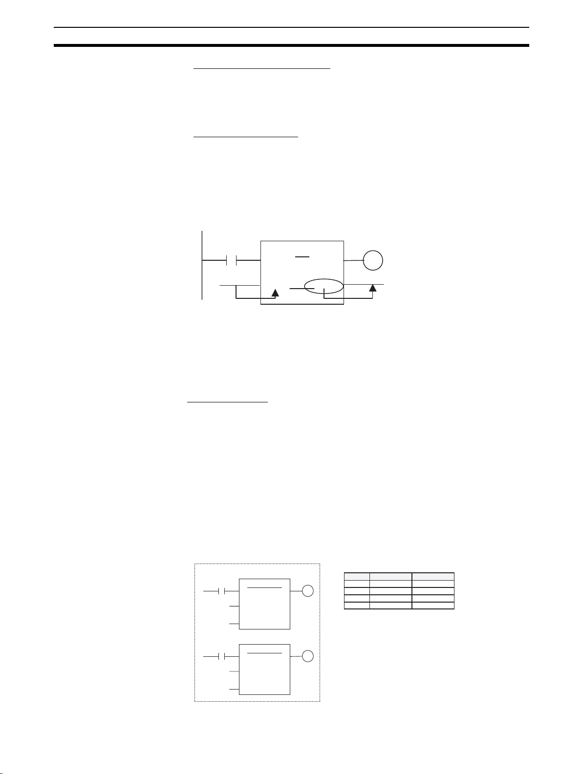
Function Block Specifications
Section 2-1
ENO (Enable Output) Variable
The ENO variable is created as the default output variable. The ENO output
variable will be turned ON when the instance is called. The user can change
this value. The ENO output variable can be used as a flag to check whether or
not instance execution has been completed normally.
Input-Output Variables
Input-output variables use addresses to pass data to and from a function
block instance. An input-output variable is displayed on both the left and right
side of the instance. The value of the input-output variable immediately after
the instance is executed is not stored in the addresses internally allocated to
the input-output variable by the system, but rather the value is stored in the
address (and following addresses depending on the data size) of the parameter used to pass data to and from the input-output variable.
P_ON
FB
1.0
EN ENO
D200
Address D200 is passed to the input-output variable CAL.
Inside the function block, the specified data size of I/O
memory starting from D200 is processed, and changes are
thus passed outside the function block instance.
CAL CAL
D200
Note Input-output variables are specified a CX-Programmer variable table by
selecting “In Out” for the variable usage.
■ Internal Variables
Internal variables are used within an instance. These variables are hidden
within each instance. They cannot be referenced from outside of the instance
and are not displayed in the instance.
The values of internal variables are retained until the next time the instance is
executed (i.e., when EN turns OFF, the value of the internal variable is
retained). Consequently, even if instances of the same function block definition are executed with the same I/O parameters, the result will not necessarily
be the same.
Example:
The internal variable tim_a in instance Pulse_2sON_1sOFF is different from
internal variable tim_a in instance Pulse_4sON_1sOFF, so the instances cannot reference and will not affect each other’s tim_a value.
Variable table
Usage
Internal
Internal
Input
Input
Name
tim_a TIMER
tim_b TIMER
ON_TIME INT
OFF_TIME INT
Data type
P_On
&20
&10
Pulse_2sON_1sOFF
CLOCK PULSE
EN ENO
ON_TIME
OFF_TIME
1.0
P_On
&40
&10
Pulse_4sON_1sOFF
CLOCK PULSE
EN ENO
ON_TIME
OFF_TIME
1.1
35
Page 61

Function Block Specifications
Section 2-1
Algorithm (Body)
0.0
ADD_INT_DINT
EN ENO
D100
IN16 OUT32
D200
IN32
Internal variable tmp
is not displayed.
Retain Data through Power Interruptions and Start of Operation
Internal variables retain the value from the last time that the instance was
called. In addition, the Retain Option can be selected so that an internal variable will also retains its value when the power is interrupted or operation
starts (the mode is switched from PROGRAM to RUN or MONITOR mode).
When the Retain Option is selected, the value of the variable is retained when
the power is interrupted or operation starts unless the CPU Unit does not
have a backup battery. If the CPU Unit does not have a good battery, the value
will be unstable.
Variables Condition Status
Variables set to Retain Start of operation Retained
10.0
D1000
EN
SIGN IN16 tmp
+L IN32 tmp OUT32
Variable table
Internal
Input
Input
Input
Output
Output
Power ON Retained
Name
tmp DINT
EN BOOL
IN16 INT
IN32 DINT
ENO BOOL
OUT32 DINT
Type
When the Retain Option is not selected, the value of the variable will not be
held when the power is interrupted or operation starts. Even variables not set
to be retained, however, can be held at the start of operation by turning ON
the IOM Hold Bit (A50012) and can be held during power interruptions by setting the PLC Setup, as shown in the following table.
Variables Condition IOM Hold Bit (A50012) setting
OFF ON
IOM Hold Bit Status at Startup
IOM Hold Bit Status at Startup
(PLC Setup) selected
Variables not
set to Retain
Start of operation Not retained Retained Retained
Power ON Not retained Retained Not retained
Note The IOM Hold Bit (A50012) is supported for compatibility with previous mod-
els. To hold the values of variables in function blocks, however, use the Retain
Option and not the IOM Hold Bit.
Initial Value
An initial value can be set for an internal variable that is not being retained
(i.e., when the Retain Option not selected). An initial value cannot be set for
an internal variable if the Retain Option is selected.
Internal variables that are not being retained will be initialized to 0.
The initial value will not be written to the internal variable if the IOM Hold Bit
(A50012) is ON
Auxiliary Area control bit Initial value
IOM Hold Bit (A50012) ON The initial value will not be set.
.
OFF The initial value will be set.
(PLC Setup) not selected
36
Page 62

Function Block Specifications
■ External Variables
External variables are either system-defined variables that have been registered in CX-Programmer before hand, or variables that externally reference
user-defined variables in the global symbol table.
• For details on system-defined variables, refer to Appendix A System-
defined external variables supported in function blocks.
• To externally reference user-defined variables in the global symbol table,
the variables of the same name and data type must be registered as an
external variable.
However, it is impossible to externally reference the variables userdefined as a network symbol.
Variable Properties Variable Name
The variable name is used to identify the variable in the function block. The
name can be up to 30,000 characters long. The same name can be used in
other function blocks.
Note A variable name must be input for variables, even ones with AT settings (spec-
ified address).
Data Type
Any of the following types may be used.
Section 2-1
Data type Content Size Inputs Outputs In Out Internals
BOOL Bit data 1 bit OK OK OK OK
INT Integer 16 bits OK OK OK OK
UNIT Unsigned integer 16 bits OK OK OK OK
DINT Double integer 32 bits OK OK OK OK
UDINT Unsigned double integer 32 bits OK OK OK OK
LINT Long (4-word) integer 64 bits OK OK OK OK
ULINT Unsigned long (4-word) integer 64 bits OK OK OK OK
WORD 16-bit data 16 bits OK OK OK OK
DWORD 32-bit data 32 bits OK OK OK OK
LWORD 64-bit data 64 bits OK OK OK OK
REAL Real number 32 bits OK OK OK OK
LREAL Long real number 64 bits OK OK OK OK
TIMER Timer (See note 1.) Flag: 1 bit
PV: 16 bits
COUNTER Counter (See note 2.) Flag: 1 bit
PV: 16 bits
STRING Text string data Variable Not sup-
Not supported
Not supported
ported
Not supported
Not supported
Not supported
Not supported
Not supported
Not supported
OK
OK
OK
Note (1) The TIMER data type is used to enter variables for timer numbers (0 to
4095) in the operands for TIMER instructions (TIM, TIMH, etc.). When
this variable is used in another instruction, the Timer Completion Flag (1
bit) or the timer present value (16 bits) is specified (depending on the instruction operand). The TIMER data type cannot be used in structured
text function blocks.
(2) The COUNTER data type is used to enter variables for counter numbers
(0 to 4095) in the operands for COUNTER instructions (CNT, CNTR,
etc.). When this variable is used in another instruction, the Counter Completion Flag (1 bit) or the counter present value (16 bits) is specified (depending on the instruction operand). The COUNTER data type cannot be
used in structured text function blocks.
37
Page 63

Function Block Specifications
Note (1) The AT property can be set for internal variables only.
Section 2-1
AT Settings (Allocation to Actual Addresses)
With internal variables, it is possible to set the variable to a particular I/O
memory address rather than having it allocated automatically by the system.
To specify a particular address, the user can input the desired I/O memory
address in this property. It is still necessary to use variable name in programming even if a particular address is specified.
(2) AT settings can be used only with the CIO (Core I/O Area), A (Auxiliary
Area), D (Data Memory Area), E (Extended Memory Area, H (Holding
Relay Area), W (Internal Relay Area).
The AT property cannot be set in the following memory areas:
• Index Register and Data Register Areas (directly/indirectly specified)
• Indirectly specified DM/EM (: binary mode, *:BCD mode)
(3) AT settings can be used for the following allocations.
• Addresses for Basic I/O Units, CPU Bus Units, or Special I/O Units
• Auxiliary Area bits not registered as external variables in advance
• PLC addresses for other nodes in the network
Example:
If the READ DATA FILE instruction (FREAD) is being used in the function
block definition and it is necessary to check the File Memory Operation Flag
(A34313), use an internal variable and specify the flag’s address in the AT setting.
Register an internal variable, select the AT setting option, and specify A34313
as the address. The status of the File Memory Operation Flag can be checked
through this internal variable.
38
Address A34313 is allocated to a
boolean internal variable named
NOW_CARD_ACCESS.
When the AT setting is used, the function block loses its flexibility. This function should thus be used only when necessary.
Array Setting
With internal variables and input-output variables, a variable can be defined
as an array.
Note Only one-dimensional arrays are supported by the CX-Programmer.
With the array setting, a large number of variables with the same properties
can be used by registering just one variable.
• An array set for an internal variable can have from 1 to 32,000 array elements. An array set for an input-output variable can have the number of
elements given in the following table.
Data type Number of elements
BOOL 2,048
INT/UINT/WORD 2,048
Page 64

Function Block Specifications
SCL
Section 2-1
Data type Number of elements
DINT/UDINT/DWORD 1,024
LINT/ULINT/LWORD 512
• An array can be set only for internal variables or input-output variables.
• Any data type except for STRING can be specified for an array variable,
as long as it is an internal variable.
• When entering an array variable name in the algorithm of a function block
definition, enter the array index number in square brackets after the variable name. The following three methods can be used to specify the index.
(In this case the array variable is a[].)
• Directly with numbers (for ladder or ST language programming)
Example: a[2]
• With a variable (for ladder or ST language programming)
Example: a[n], where n is a variable
Note INT, DINT, LINT, UINT, UDINT, or ULINT can be used as the vari-
able data type.
• With an equation (for ST language programming only)
Example: a[b+c], where b and c are variables
Note Equations can contain only arithmetic operators (+, −, *, and /).
An array is a collection of data elements that are the same type of data. Each
array element is specified with the same variable name and a unique index.
(The index indicates the location of the element in the array.)
A one-dimensional array is an array with just one index number.
Example: When an internal variable named SCL is set as an array variable
with 10 elements, the following 10 variables can be used:
SCL[0], SCL[1], SCL[2], SCL[3], SCL[4], SCL[5], SCL[6], SCL[7], SCL[8], and
SCL[9]
0
WORD variable
1
WORD variable
2
WORD variable
3
WORD variable
4
WORD variable
5
WORD variable
6
WORD variable
7
WORD variable
8
WORD variable
9
WORD variable
Specify SCL[3] to access this data element.
Settings for variable SCL as an array
variable with element numbers 0 to 9.
Note Use an array variable when specifying the first or last of multiple words in an
instruction operand to enable reusing the function block if an internal variable
with a AT property cannot be set for the operand and an external variable cannot be set. When using an array setting for an input-output variable, specify
the address of the first word for the input parameter (CX-Programmer version
7.0 or higher). When using an array setting for an internal variable, prepare an
array variable with the number of elements for the required size, and after set-
39
Page 65

Function Block Specifications
Section 2-1
ting the data in each array element, specify the first or last element in the
array variable for the operand.
Example:
Function block definition Instance
Variable
SCL WORD[10]
Algorithm
SCL-BODY
LD P_On
MOV #0000 SCL[0]
MOV &0SCL[1]
MOV #0300 SCL[2]
MOV &4000 SCL[3]
SCL S SCL[0] D
SCL
0 #0000
1&0
2 #0300
3 &4000
Write the operand data
to the array variables.
Specify the beginning of the
array in the SCL instruction.
SCL
EN
S D
ENO
100
Specifying this array element in
the SCL instruction is the same
as specifying the first address.
Note For details, refer to 2-6 Precautions for Instructions with Operands Specifying
the First or Last of Multiple Words.
Initial Values
When an instance is executed the first time, initial values can be set for input
variables, internal variables, and output variables. For details, refer to Initial
Value under the preceding descriptions of input variables, internal variables,
and output variables.
Retaining Data through Power Interruptions and Start of Operation
The values of internal variables can be retained through power interruptions
and the start of operation. When the Retain Option is selected, the variable
will be allocated to a region of memory that is retained when the power is
interrupted and PLC operation starts.
Algorithm Enter the logic programming using the registered variables.
Operand Input
Restrictions
Note Exception: Input directly or indirectly specified addresses for Index Registers
Addresses cannot be directly input into instruction operands within function
blocks. Addresses that are directly input will be treated as variable names.
IR0 to IR15 and Data Registers DR0 to DR15 directly into the instruction
operand. Do not input variables.
Input constants directly into instruction operands.
• Ladder programming: Enter decimal values after the &, and enter
hexadecimal numerical values after the #.
40
Page 66

Data Types Supported in Function Blocks
Section 2-2
• Structured text (ST language): Enter decimal numerical values as is
and enter hexadecimal numerical values after 16#.
Comment A comment of up to 30,000 characters long can be entered.
2-2 Data Types Supported in Function Blocks
2-2-1 Basic Data Types
Data type Content Size Range of values
BOOL Bit data 1 0 (FALSE), 1 (TRUE)
INT Integer 16 −32,768 to +32,767
DINT Double integer 32 −2,147,483,648 to +2,147,483,647
LINT Long (8-byte) integer 64 −9,223,372,036,854,775,808 to +9,223,372,036,854,775,807
UINT Unsigned integer 16 &0 to 65,535
UDINT Unsigned double integer 32 &0 to 4,294,967,295
ULINT Unsigned long (8-byte)
integer
REAL Real number 32
LREAL Long real number 64
WORD 16-bit data 16 #0000 to FFFF or &0 to 65,535
DWORD 32-bit data 32 #00000000 to FFFFFFFF or &0 to 4,294,967,295
LWORD 64-bit data 64 #0000000000000000 to FFFFFFFFFFFFFFFF or
STRING Text string (See note.) Variable 1 to 255 ASCII characters
TIMER Timer Flag: 1 bit
COUNTER Counter Flag: 1 bit
FUNCTION
BLOCK
Function block instance --- ---
64 &0 to 18,446,744,073,709,551,615
PV: 16 bits
PV: 16 bits
−3.402823 × 1038 to −1.175494 × 10
+1.175494 × 10
−1.79769313486232 × 10
2.22507385850720 × 10
&0 to 18,446,744,073,709,551,615
Timer number: 0 to 4095
Completion Flag: 0 or 1
Timer PV: 0 to 9999 (BCD), 0 to 65535 (binary)
Counter number: 0 to 4095
Completion Flag: 0 or 1
Counter PV: 0 to 9999 (BCD), 0 to 65535 (binary)
−38
to +3.402823 × 10
308
to −2.22507385850720 × 10
−308
to 1.79769313486232 × 10
−38
, 0,
38
−308
308
, 0,
Note The TIMER and COUNTER data types cannot be used in structured text func-
tion blocks.
2-2-2 Derivative Data Types
Array 1-dimensional array; 32,000 elements max.
41
Page 67

Instance Specifications
2-3 Instance Specifications
2-3-1 Composition of an Instance
The following table lists the items that the user must set when registering an
instance.
Item Description
Instance name Name of the instance
Language
Variable definitions
Function block instance areas The ranges of addresses used by the variables
Comments A comment can be entered for each instance.
Instance Name This is the name of the instance.
• Instance names can be up to 30,000 characters long.
• Instance names cannot contain spaces or any of the following characters:
!“#$%&‘()=-~^\|‘@{[+;*:}]<,>.?/
• Instance names cannot start with a number (0 to 9).
There are no other restrictions.
The instance name is displayed above the instance in the diagram.
Pulse_2sON_2sOFF
CLOCK PULSE
EN
ENO
&20
ON_TIME
&10
OFF_TIME
The programming and variables are the same as in
the function block definition.
Instance name
Section 2-3
Function Block
Instance Areas
To use a function block, the system requires memory to store the instance’s
internal variables, input variables, output variables, and input-output variables.
These areas are known as the function block instance areas and the user
must specify the first addresses and sizes of these areas. The first addresses
and area sizes can be specified in 1-word units.
When the CX-Programmer compiles the function, it will output an error if there
are any instructions in the user program that access words in these areas.
42
Page 68

Instance Specifications
Section 2-3
CJ2-series CPU Units
FB Instance
Area
Non Retain H512 H1407 896 CIO, WR, HR, DM,
Retain H1408 H1535 128 HR, DM, EM (See note.)
Timers T3072 T4095 1024 TIM
Counters C3072 C4095 1024 CNT
Start address End address Size
Note Force-setting/resetting is enabled when the following EM banks are specified:
CJ2H-CPU64(-EIP)/-CPU65(-EIP) EM bank 3
CJ2H-CPU66(-EIP) EM banks 6 to 9
CJ2H-CPU67(-EIP) EM banks 7 to E
CJ2H-CPU68(-EIP) EM banks 11 to 18
CS/CJ-series CPU Units Ver. 3.0 or Later, and NSJ Controllers
Default value Applicable memory
areas
EM (See note.)
FB Instance
Area
Non Retain H512 H1407 896 CIO, WR, HR, DM, EM
Retain H1408 H1535 128 HR, DM, EM
Timers T3072 T4095 1024 TIM
Counters C3072 C4095 1024 CNT
Start address End address Size
Default value Applicable memory
areas
FQM1 Flexible Motion Controllers
FB Instance
Area
Non Retain 5000 5999 1000 CIO, WR, DM
Retain None
Timers T206 T255 50 TIM
Counters C206 C255 50 CNT
Start address End address Size
Default value Applicable memory
areas
CP-series CPU Units
FB Instance
Area
Non Retain H512 H1407 896 CIO, WR, HR, DM (See
Retain H1408 H1535 128 HR, DM (See note.)
Timers T3072 T4095 1024 TIM
Counters C3072 C4095 1024 CNT
Start address End address Size
Default value Applicable memory
areas
note.)
Note DM area of CP1L-L
Address CP1L-L
D0000 to D9999 Provided
D10000 to D31999 Not Provided
D32000 to D32767 Provided
43
Page 69

Instance Specifications
Section 2-3
Function Block Instance
Area Types
Note (1) Except when the data type is set to TIMER or COUNTER.
The following settings are made in the function block instance area:
CS/CJ-series CPU Units Ver. 3.0 or Later, CP-series PLCs, and NSJ
Controllers
Non-retained Areas
Item Contents
Allocated variables Variables for which the retain property for power OFF and
operation start is set as non-retained (See note 1.)
Applicable areas H (Function block Special Holding Area), I/O (CIO Area), H
Setting unit Set in words
Allocated words
(default)
(Holding Area), W (Internal Relay Area), D (Data Memory
Area) (see note 2), E (Extended Data Memory Area) (See
notes 2 and 3.)
H512 to H1407
(2) Bit data can be accessed even if the DM or EM Area is specified for the
non-retained area or retained area.
(3) The same bank number cannot be specified as the current bank in the
user program if the EM Area is specified for the non-retained area or retained area.
Retained Area
Item Contents
Allocated variables Variables for which the retain property for power OFF and
operation start is set as retained (See note 1.)
Applicable areas H (Function block Special Holding Area), H (Holding Area), D
(Data Memory Area) (see note 1), E (Extended Data Memory
Area) (See notes 2 and 3.)
Setting unit Set in words
Allocated words
(default)
H1408 to H1535
Note (1) Except when the data type is set to TIMER or COUNTER.
(2) Bit data can be accessed even if the DM or EM Area is specified for the
non-retained area or retained area.
(3) The same bank number cannot be specified as the current bank in the
user program if the EM Area is specified for the non-retained area or retained area.
Timer Area
Item Contents
Allocated variables Variables with TIMER set as the data type.
Applicable areas T (Timer Area) Timer Flag (1 bit) or timer PVs (16 bits)
Allocated words
(default)
T3072 to T4095 Timer Flag (1 bit) or timer PVs (16 bits)
Counter Area
Item Contents
Allocated variables Variables with COUNTER set as the data type.
Applicable areas C (Counter Area) Counter Flag (1 bit) or counter PVs (16 bits)
Allocated words
(default)
C3072 to C4095 Counter Flag (1 bit) or counter PVs (16 bits)
44
Page 70

Instance Specifications
Section 2-3
Function Block Holding Area (H512 to H1535)
The default allocation of Function Block Holding Area words set as retained
and non-retained words is H512 to H1535. These words are different to the
standard Holding Area used for programs (H000 to H511), and are used only
for the function block instance area (internally allocated variable area).
• These words cannot be specified in AT settings for internal variables.
• These words cannot be specified as instruction operands.
• These words are displayed in red if they are input when a function
block is not being created.
• Although the words can be input when creating a function block, an
error will occur when the program is checked.
• If this area is specified as non-retained, turn the power ON/OFF or clear
the area without retaining the values when starting operation.
Note To prevent overlapping of instance area addresses with addresses used in the
program, set H512 to H1535 (Function Block Holding Area words) for the nonretained area and retained area. If there are not sufficient words, use words in
areas not used by the user program.
FQM1 Flexible Motion controller
FB Instance
Area
Non Retain 5000 5999 1000 CIO, WR, DM
Retain None
Timers T206 T255 50 TIM
Counters C206 C255 50 CNT
Start address End address Size
Default value Applicable memory
areas
Non-retained Areas
Item Contents
Allocated variables Variables for which the retain property for power OFF and
Applicable areas I/O (CIO), W (Work Area), and D (DM Area) (See note 2.)
Setting unit Set in words
Allocated words
(default)
operation start is set as retained. (See note 1.)
CIO 5000 to CIO 5999
Note (1) Except when the data type is set to TIMER or COUNTER.
(2) Bit data can be accessed even if the DM Area is specified for the non-re-
tained area.
Retained Area
None
Timer Area
Item Contents
Allocated variables Variables with TIMER set as the data type.
Applicable areas T (Timer Area) Timer Flag (1 bit) or timer PVs (16 bits)
Allocated words
(default)
T206 to T255 Timer Flag (1 bit) or timer PVs (16 bits)
Counter Area
Item Contents
Allocated variables Variables with COUNTER set as the data type.
45
Page 71

Instance Specifications
Section 2-3
Item Contents
Applicable areas C (Counter Area) Counter Flag (1 bit) or counter PVs (16 bits)
Allocated words
(default)
C206 to C255 Counter Flag (1 bit) or counter PVs (16 bits)
Accessing Function Block
Instance Area from the
User Program
Note The allocations in the function block instance area for variables are automati-
If the user program contains an instruction to access the function block
instance area, an error will be displayed in the Compile Tab of the Output Window of CX-Programmer if the following operations are attempted.
• Attempting to write during online editing (writing not possible)
• Executing program check (Selecting Compile from the Program Menu or
Compile All PLC Programs from the PLC Menu)
Example: If W0 to W511 is specified as the non-retained area of the function
block instance area and W0.00 is used in the ladder program, an error will
occur when compiling and be displayed as “ERROR: [omitted]...- Address W0.00 is reserved for Function Block use].
Program
FB
EN ENO
1.0P_Off
3.0W0.00
Instance data area
Non Retain
Retain
Timers
Counters
Compile error
Start
address
W0 512
Size
cally reallocated when a variable is added or deleted. A single instance
requires addresses in sequence, however, so if addresses in sequence cannot be obtained, all variables will be allocated different addresses. As a result,
unused areas will be created. If this occurs, execute the optimization operation to effectively use the allocated areas and remove the unused areas.
Comments A comment of up to 30,000 characters long can be entered.
Creating Multiple
Instances
Calling the Same Instance A single instance can be called from multiple locations. In this case, the inter-
nal variables will be shared.
Making Multiple Instances Multiple instances can be created from a single function block definition. In
this case, the values of internal variables will be different in each instance.
Example: Counting Product A and Product B
Prepare a function block definition called Down Counter (CTD) and set up
counters for product A and product B. There are two types of programs, one
for automatic operation and another for manual operation. The user can
switch to the appropriate mode of operation.
In this case, multiple instances will be created from a single function block.
The same instance must be called from multiple locations.
46
Page 72

Instance Specifications
Section 2-3
Program 1 (automatic operation)
Product A counter
CTD
CD Q
LD
PV CV
Product B counter
CTD
CD Q
LD
PV CV
Program 1
Program 2
Instance A
FB
Instance B
FB
Instance A
FB
D100
D200
Program 2 (manual operation)
Product B counter
CTD
CD Q
LD
PV CV
Reading the same product’s counter
value at different locations
Reading different products’ counter values
(Algorithm calculating counter value is the same.)
Instance A
I/O variables,
Internal
variables
Body
Instance B
I/O variables,
Internal
variables
Body
FB definition
Variable
definitions
Body
D150
Use the same internal variables
Use different internal variables
2-3-2 Parameter Specifications
The data that can be set by the user in the input parameters and output
parameters is as follows:
Item Applicable data
Input parameters Values (See note 1.), addresses, and program symbols (glo-
Output parameters Addresses, program symbols (global symbols, local symbols)
Input-output parameters
Note (1) The following table shows the methods for inputting values in parameters.
Input
variable
data type
BOOL Bit data 1 bit P_Off, P_On 0 (FALSE), 1 (TRUE)
Contents Size Parameter value input
bal symbols and local symbols) (See note 2.)
Note The data that is passed to the input variable from the
parameter is the actual value of the size of the input
variable data. (An address itself will not be passed even
if an address is set in the parameter.)
Note Input parameters must be set. If even one input param-
eter has not been set, a fatal error will occur and the
input parameters will not be transferred to the actual
PLC.
(See note 2.)
Addresses, program symbols (global symbols, local symbols)
Setting range
method
47
Page 73

Instance Specifications
Section 2-3
Input
variable
data type
INT Integer 16 bits Positive value: & or + followed
DINT Double integer 32 bits −2,147,483,648 to 2,147,483,647
LINT Long (8-byte) integer 64 bits −9,223,372,036,854,775,808 to
UINT Unsigned integer 16 bits Positive value: & or + followed
UDINT Unsigned double integer 32 bits &0 to 4,294,967,295
ULINT Unsigned long (8-byte)
integer
REAL Real number 32 bits Positive value: & or + followed
LREAL Long real number 64 bits
WORD 16-bit data 16 bits # followed by hexadecimal
DWORD 32-bit data 32 bits # followed by hexadecimal
LWORD 64-bit data 64 bits # followed by hexadecimal
Contents Size Parameter value input
by integer
Negative value: − followed by
integer
by integer
64 bits &0 to 18,446,744,073,709,551,615
by real number (with decimal
point)
Negative value:
real number (with decimal
point)
number (4 digits max.)
& or + followed by decimal
number
number (8 digits max.)
& or + followed by decimal
number
number (16 digits max.)
& or + followed by decimal
number
method
− followed by
Setting range
−32,768 to 32,767
9,223,372,036,854,775,807
&0 to 65,535
−3.402823 × 10
−38
10
, 0, 1.175494 × 10
3.402823 × 1038
−1.79769313486232 × 10
−2.22507385850720 × 10
2.22507385850720 × 10
1.79769313486232 × 10
#0000 to FFFF or &0 to 65,535
#00000000 to FFFFFFFF or &0 to
4,294,967,295
#0000000000000000 to
FFFFFFFFFFFFFFFF or &0 to
18,446,744,073,709,551,615
38
to −1.175494 ×
−38
to
308
−308
−308
308
to
, 0,
,
(2) The size of function block input variables and output variables must
match the size of program symbols (global and local), as shown in the following table.
Size Function block variable data
type
1 bit BOOL BOOL
16 bits INT, UINT, WORD INT, UINT, UINT BCD, WORD
32 bits DINT, UDINT, REAL, DWORD DINT, UDINT, UDINT BCD, REAL,
64 bits LINT, ULINT, LREAL, LWORD LINT, ULINT, ULINT BCD, LREAL,
More than 1
bit
Non-boolean CHANNEL, NUMBER (see note)
Program symbol (global, local)
data type
DWORD
LWORD
Note The program symbol NUMBER can be set only in the input param-
eters. The value that is input must be within the size range for the
function block variable data type.
48
Page 74

Instance Specifications
Section 2-3
2-3-3 Operating Specifications
Calling Instances The user can call an instance from any location. The instance will be executed
when the input to EN is ON.
0.0
D0
Instance
EN ENO
A B
1.0
In this case, the input to EN is bit 0.0 at the left of the diagram.
• When the input to EN is ON, the instance is executed and
D10
the execution results are reflected in bit 1.0 and word D10.
• When the input to EN is OFF, the instance is not executed,
bit 1.0 is turned OFF, and the content of D10 is not changed.
Operation when the
Instance Is Executed
The system calls a function block when the input to the function block’s EN
input variable is ON. When the function block is called, the system generates
the instance’s variables and copies the algorithm registered in the function
block. The instance is then executed.
Pulse_2sON_1sOFF
P_On
Algorithm (Image)
CLOCK PULSE
EN ENO
&20
ON_TIME
&10
OFF_TIME
Usage
Internal
Internal
Input
Input
Pulse_2sON_1sOFF tim_b
Pulse_2sON_1sOFF tim_a
Pulse_2sON_1sOFF tim_a
Pulse_2sON_1sOFF tim_b Pulse_2sON_1sOFF ON_TIME
1.0
1. The FB is called.
2. The system generates the instance
variables and copies the algorithm.
FB instance (Pulse_2sON_1sOFF)
Name
200-100ms_PULSE_tim_a
200-100ms_PULSE_tim_b
200-100ms_PULSE_ON_TIME
200-100ms_PULSE_OFF_TIME
Pulse_2sON_1sOFF ENO
---
--&20
&10
Pulse_2sON_1sOFF OFF_TIME
Value
Algorithm (Body)
tim_b
tim_a
3. The contents of the
TIMX tim_a OFF_TIME
TIMX tim_b ON_TIME
ENO
instance are executed.
The order of execution is as follows:
1. Read data from parameters to input variables.
2. Execute the algorithm.
3. Write data from output variables to parameters.
Input to EN is ON.
Parameters
1. Read values from parameters
to input variables.
2. Execute the algorithm.
3. Write values from output
variables to parameters.
Parameters
Data cannot be exchanged with parameters in the algorithm itself.
In addition, if an output variable is not changed by the execution of the algorithm, the output parameter will retain its previous value.
49
Page 75

Instance Specifications
a
Section 2-3
Operation when the
Instance Is Not Executed
!Caution An instance will not be executed while its EN input variable is OFF, so Differ-
When the input to the function block’s EN input variable is OFF, the function
block is not called, so the internal variables of the instance do not change (values are retained). In the same way the output variables do not change when
EN is OFF (values are retained).
Program
FB
EN ENO
Execution results:
Output variable 1.0 is turned OFF, but
internal variable a retains its previous value.
Program
Internal
variable a
1.0P_Off
1.0P_Off P_On
FB definition
Body
P_On
ENO
Internal
variable a
If the programming were entered
directly into the program instead of in
function block definition, both bit 1.0
and variable a would be turned OFF.
entiation and Timer instructions will not be initialized while EN is OFF. If Differentiation or Timer instructions are being used, use the Always ON Flag
(P_On) for the EN input condition and include the instruction’s input condition
within the function block definition.
Nesting With CX-Programmer Ver. 6.0 and later versions, a function block can be
called from another function block, i.e., nesting is supported. Function blocks
can be nested up to 8 levels (including the function block called from the program).
The calling function block and called function block can be either ST language, ladder language, or either combination of the two.
Program
INSTANCE_FB0
FB0
FB0: Ladder diagram
INSTANCE_FB1
1st
Example:
INSTANCE_FB1 (A:=FB1__OUT1,B=:>FB1_IN1)
FB1
FB0 (ST)
"INSTANCE_FB1," "INSTANCE_FB2," etc., are the FUNCTION BLOCK data type instance names.
Note: Any combination of ladder diagrams and structured text programming can be used between the called and the calling function block.
FB1: Ladder diagram
2nd
;
Example:
INSTANCE_FB2 (...,..)
INSTANCE_FB2
FB2
FB1 (ST)
7th
FB7: Ladder diagram
INSTANCE_FB8
FB8
FB7 (ST)
Example:
INSTANCE_FB8 (...,..)
8th
FB8: Ladder diagram
FB8 (ST)
Example:
The function block nesting levels can also be displayed in a directory tree format with the FB Instance Viewer function.
The nested function blocks’ function block definitions are included in the function block library file (.cxf) containing the calling function block’s definitions.
50
Page 76

Programming Restrictions
2-4 Programming Restrictions
2-4-1 Ladder Programming Restrictions
There are some restrictions on instructions used in ladder programs.
Section 2-4
Instructions Prohibited in
Function Block Definitions
AT Setting Restrictions
(Unsupported Data Areas)
Direct Addressing of I/O
Memory in Instruction
Operands
Restrictions for Input
Variables, Output
Variables, and InputOutput Variables
(Unsupported Data Areas)
Refer to the Programmable Controllers Instructions Reference Manual (Cat.
No. W474)
Addresses in the following areas cannot be used for AT settings.
• Index Registers (neither indirect nor direct addressing is supported) and
Data Registers
Note Input the address directly, not the AT setting.
• Indirect addressing of DM or EM Area addresses (Neither binary-mode
nor BCD-mode indirect addressing is supported.)
• Addresses, not variables, can be directly input in Index Registers (both
indirect and direct addressing) and Data Registers.
The following values can be input in instruction operands:
Direct addressing: IR0 to IR15; Indirect addressing: ,IR0 to ,IR15; Constant offset (example): +5,IR0; DR offset: DR0,IR0; Auto-increment:
,IR0++; Auto-decrement: --,IR0
• Direct addressing in instruction operands is not supported for any other
areas in I/O memory.
Addresses in the following data areas cannot be used as parameters for input
variables, output variables, and input-output variables.
• Index Registers (neither indirect nor direct addressing is supported) and
Data Registers
• Indirect addressing of DM or EM Area addresses (Neither binary-mode
nor BCD-mode indirect addressing is supported.)
Interlock Restrictions When a function block is called from an interlocked program section, the con-
tents of the function block definition will not be executed. The interlocked function block will behave just like an interlocked subroutine.
P_Off
Differentiation
Instructions in Function
Block Definitions
IL
FB
ILC
Interlocked
An instance will not be executed while its EN input variable is OFF, so the following precautions are essential when using a Differentiation Instruction in a
function block definition. (Differentiation Instructions include DIFU, DIFD, and
FB_BODY
Interlock will not
affect instructions in
the function block
definition.
any instruction with an @ or % prefix.)
• As long as the instance’s EN input variable is OFF, the execution condition
will retain its previous status (the last status when the EN input variable
was ON) and the Differentiation Instruction will not operate.
51
Page 77
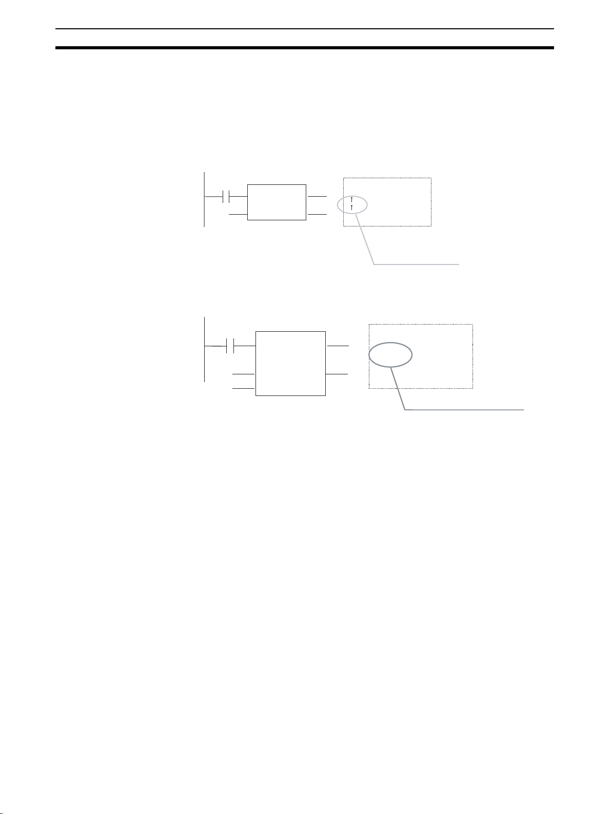
Programming Restrictions
Section 2-4
• When the instance’s EN input variable goes ON, the present execution
condition status will not be compared to the last cycle’s status. The
present execution condition will be compared to the last condition when
the EN input variable was ON, so the Differentiation Instruction will not
operate properly. (If the EN input variable remains ON, the Differentiation
Instruction will operate properly when the next rising edge or falling edge
occurs.)
Example:
0.0
FB1
EN ENO
IN1 OUT1
LD EN
OR IN1
SET OUT1
Body
These Differentiation Instructions do not
operate when input condition 0.00 goes
from OFF to ON the first time.
The instructions do not operate while
input condition 0.00 is OFF.
If Differentiation Instructions are being used, always use the Always ON Flag
(P_On) for the EN input condition and include the instruction’s input condition
within the function block definition.
P_On
0.00
FB1
EN ENO
a O UT1
IN 1
LD a
OR IN1
SET OUT1
Body
The EN input condition is always ON, so
these Differentiation Instructions operate
normally.
• Input a decimal numerical value after “#” when specifying the first operand
of the following instructions.
MILH(517), MILR(518), MILC(519), DIM(631), MSKS(690), MSKR(692),
CLI(691), FAL(006), FALS(007), TKON(820), TKOF(821)
Note “&” is not supported.
• CNR(545), CNRX(547) (RESET TIMER/COUNTER) instructions cannot
be used to reset multiple timers and counters within a function block at the
same time.
Always specify the same variable for the first operand (timer/counter number 1) and second operand (timer/counter number 2). Different variables
cannot be specified for the first and second operand.
Timer Instructions in
Function Block Definitions
52
An instance will not be executed while its EN input variable is OFF, so the following precautions are essential when using a Timer Instruction in a function
block definition.
The Timer Instruction will not be initialized even though the instance’s EN
input variable goes OFF. Consequently, the timer’s Completion Flag will not be
turned OFF if the EN input variable goes OFF after the timer started operating.
Page 78

Programming Restrictions
Section 2-4
0.00
FB1
EN ENO
U P
If Timer Instructions are being used, always use the Always ON Flag (P_On)
for the EN input condition and include the instruction’s input condition within
the function block definition.
P_On
0.00
FB1
EN ENO
a U P
• If the same instance containing a timer is used in multiple locations at the
same time, the timer will be duplicated.
2-4-2 ST Programming Restrictions
Body
LD EN
TIM t im UP
The timer’s Completion Flag (UP)
will not be turned OFF even though
input condition 0.00 goes OFF.
Body
LD a
TIM t im UP
The timer’s completion flag (UP) is turned
OFF when input condition a (0.00) goes OFF.
Restrictions when
Using ST Language in
Function Blocks
• Only the following statements and operators are supported.
• Assignment statements
• Selection statements (CASE and IF statements)
• Iteration statements (FOR, WHILE, REPEAT, and EXIT statements)
• RETURN statements
• Function block calling statements
• Arithmetic operators
• Logical operators
• Comparison operators
• Numerical functions
• Arithmetic functions
• Standard text string functions
• Numeric text string functions
• OMRON expansion functions
• Comments
• The TIMER and COUNTER data types cannot be used.
For further details, refer to SECTION 5 Structured Text (ST) Language Speci-
fications in Part 2: Structured Text (ST).
53
Page 79
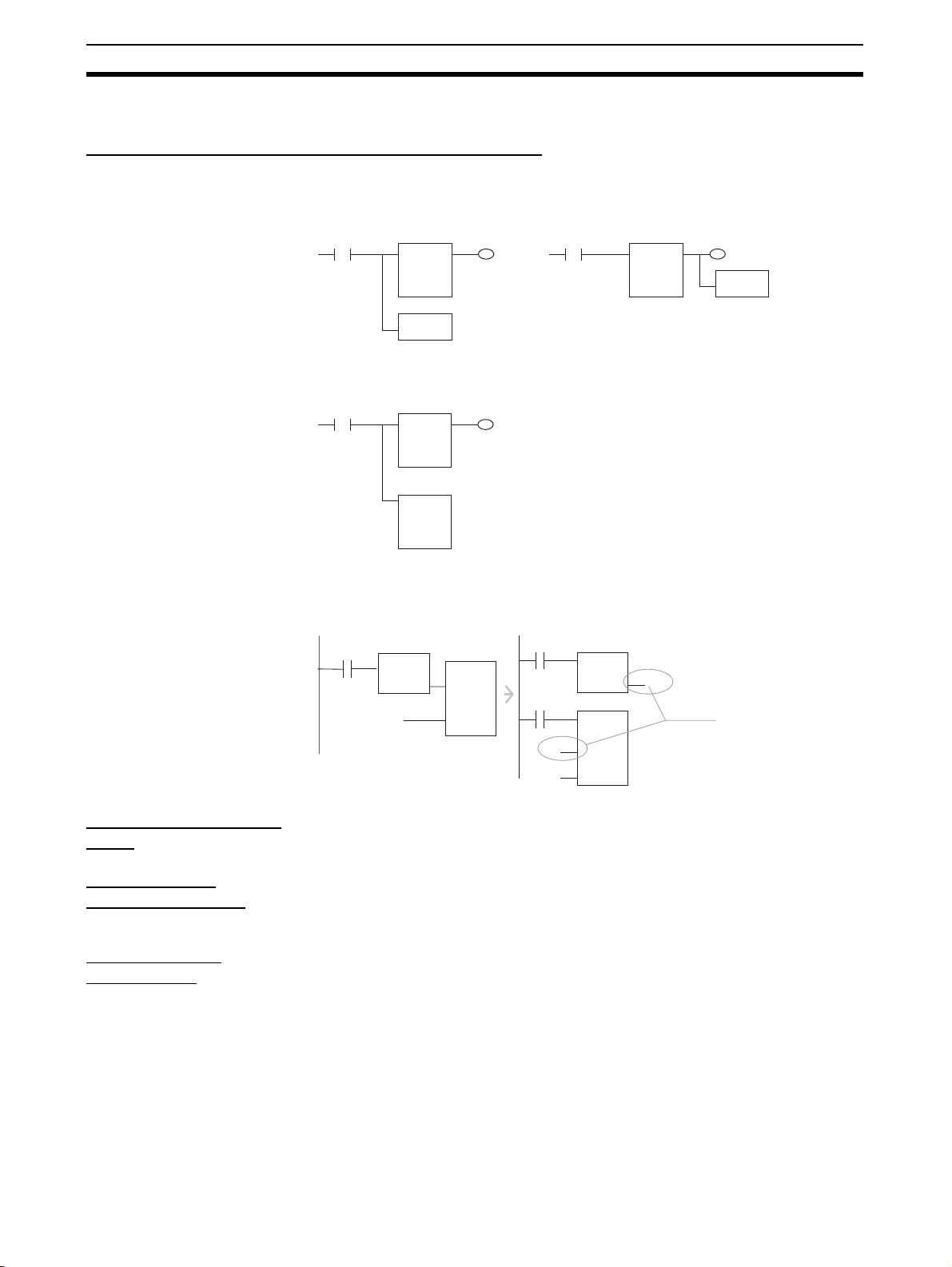
Programming Restrictions
2-4-3 Programming Restrictions
Restrictions in Locating Function Block Instances
Section 2-4
No Branches to the Left of
the Instance
Only One Instance per
Rung
No Function Block
Connections
Branches are not allowed on the left side of the instance. Branches are
allowed on the right side.
Incorrect Correct
FB FB
Instruction
Instruction
A program rung cannot have more than one instance.
Incorrect Correct
FB
FB
FB
A function block’s input cannot be connected to another function block’s output. In this case, a variable must be registered to transfer the execution status
from the first function block’s output to the second function blocks input.
Downloading in Task
Units
Programming
Console Displays
Online Editing
Restrictions
0.0
FB1
EN
XOUT
D100
XIN1
XIN2
FB2
0.0
FB1
EN
0.0
EN
D3000
XIN1
D100
XIN2
XOUT
FB2
D3000
Temporary variables
transfer the value from
FB1 to FB2.
Tasks including function blocks cannot be downloaded in task units, but
uploading is possible.
When a user program created with the CX-Programmer is downloaded to the
CPU Unit and read by a Programming Console, the instances will all be displayed as question marks. (The instance names will not be displayed.)
The following online editing operations cannot be performed on the user program in the CPU Unit.
• Changing or deleting function block definitions (variable table or algorithm)
• Inserting instances or changing instance names
Note The instance’s I/O parameters can be changed, instances can be
deleted, and instructions outside of an instance can be changed.
54
Page 80

Programming Restrictions
Section 2-4
Error-related
Restrictions
Prohibiting Access to
FB Instance Areas
If a fatal error occurs in the CPU Unit while a function block definition is being
executed, ladder program execution will stop at the point where the error
occurred.
Program FB definition
BodyInstance name
0.0
FB
EN ENO
AAA BBB
10.0
D200D100
LD P_On
++ AAA
Fatal error occurs here.
MOV AAA BBB
In this case, the MOV AAA BBB instruction will not be executed and output
variable D200 will retain the same value that it had before the function block
was executed.
To use a function block, the system requires memory areas to store the
instance’s internal variables, input variables, output variables, and input-output variables.
CJ2-series CPU Units
Function block instance
area
Non-retained H512 896 CIO, WR, HR, DM,
Retained H1408 128 HR, DM, EM (See
Timer T3072 1024 TIM
Counter C3072 1024 CNT
Initial value of
start address
Initial value
of size
Allowed data areas
EM (See note.)
note.)
Note Force-setting/resetting is enabled when the following EM banks are specified:
CJ2H-CPU64(-EIP)/-CPU65(-EIP) EM bank 3
CJ2H-CPU66(-EIP) EM banks 6 to 9
CJ2H-CPU67(-EIP) EM banks 7 to E
CJ2H-CPU68(-EIP) EM banks 11 to 18
CS/CJ-series CPU Units Ver. 3.0 or Later, and NSJ Controllers
Function block instance
area
Non-retained H512 896 CIO, WR, HR, DM, EM
Retained H1408 128 HR, DM, EM
Timer T3072 1,024 TIM
Counter C3072 1,024 CNT
Initial value of
start address
Initial value
of size
Allowed data areas
FQM1 Flexible Motion Controllers
FB Instance
Area
Start address End address Size
Non Retain 5000 5999 1000 CIO, WR, DM
Retain None
Timers T206 T255 50 TIM
Counters C206 C255 50 CNT
Default value Applicable memory
areas
55
Page 81

Function Block Applications Guidelines
CP-series CPU Units
Function block instance
Non-retained H512 896 CIO, WR, HR, DM
Retained H1408 128 HR, DM (See note.)
Timer T3072 1024 TIM
Counter C3072 1024 CNT
Note DM area of CP1L-L
Address CP1L-L
D0000 to D9999 Provided
D10000 to D31999 Not Provided
D32000 to D32767 Provided
If there is an instruction in the user program that accesses an address in an
FB instance area, the CX-Programmer will output an error in the following
cases.
• When a program check is performed by the user by selecting Program -
Compile from the Program Menu or Compile All Programs from the
PLC Menu.
• When attempting to write the program through online editing (writing is
not possible).
area
Initial value of
start address
Initial value
of size
Section 2-5
Allowed data areas
(See note.)
2-5 Function Block Applications Guidelines
This section provides guidelines for using function blocks with the CX-Programmer.
2-5-1 Deciding on Variable Data Types
Integer Data Types
(1, 2, or 4-word Data)
Note Use signed integers if the numbers being used will fit in the range.
Word Dat a Types
(1, 2, or 4-word Data)
Text St ring Data Use the following data type for text string data.
Use the following data types when handling single numbers in 1, 2, or 4-word
units.
• INT and UINT
• DINT and DINT
• LINT and ULINT
Use the following data types when handling groups of data (non-numeric
data) in 1, 2, or 4-word units.
•WORD
•DWORD
•LWORD
•STRING
56
Page 82

Function Block Applications Guidelines
Section 2-5
2-5-2 Determining Variable Types (Inputs, Outputs, In Out, Externals,
and Internals)
Using Input Variable to
Change Passed Values
To paste a function block into the program and then change the value (not the
address itself) to be passed to the function block for each instance, use an
input variable.
Program
Instance for function block definition A
The value itself is
passed
&3 Unit No.
&50
Changing the pass value to an input variable.
PARA
The following two restrictions apply.
• An address can be set in an input parameter, but an address itself cannot
be passed to an input variable (even if an address is set in the input
parameter, the value for the size of the input variable data type is passed
to the function block). Therefore, when the first or last of multiple words is
specified in the instruction operand within the function block, an input variable cannot be used for the operand. Specify either to use internal variables with AT settings, specify the first or last element in an input-output
array variable (set the input parameter to the first address) (CX-Programmer version 7.0 or higher), specify the first or last element in an internal
array variable, or use an external variable (as described in 2-5-4 Array
Settings for Input-Output Variables and Internal Variables).
Program
Instance for function block definition A
The actual value is
passed
D00100 DATA_1
W500
DATA_2
The address can be specified, but the address itself is not passed.
If the size of the data type in
DATA_1 is 1 word, the value
for the word D00100 is
passed.
If the size of the data type in
DATA_2 is 2 words, the value
for the 2 words W500 and
W501 is passed.
An input variable cannot be used to specify
the address of an operand that specifies
the first (or last) address of multiple words.
For example, the XFER (BLOCK
TRANSFER) instruction cannot be used to
transfer 10 words from the address
beginning with DATA_1 to the address
beginning with DATA_2.
XFER
&10
DATA_1
DATA_2
• Values are passed in a batch from the input parameters to the input variables before algorithm execution (not at the same time as the instruction
in the algorithm is executed). Therefore, to pass the value from a parameter to an input variable when the instruction in the function block algorithm
is executed, use an internal variable or external variable instead of an
input variable.
57
Page 83

Function Block Applications Guidelines
(
)
Section 2-5
Passing Values from or
Monitoring Output
Variabl es
Input-Output Variables to
Return FB Processing
Results from Values
Passed from Input
Parameters to Output
Parameters
To paste into the program and then pass values outside (the program) from
the function block for each instance, or monitor values, use output variables.
Program
Instance for function block definition A.
The actual value is
passed.
OK_Flag
NG_F lag
W0. 00
W0. 01
Variable for passing a value outside or monitoring:
Use an output variable.
The following restrictions apply.
• Values are passed from output variables to output parameters all at once
after algorithm execution.
An input-output variable can be used to implement the functionality of both
input and output parameters. Internal operation involves passing the address
set for the parameter to the input-output variable, but the use of the input-output variable inside the function block is the same as that of other variables.
Program Section
Instance of FB definition A
Specify an address for the input parameter;
the address will be passed to the FB.
Input-Output Array
Variables to Pass Large
Amounts of Data
D100
a a
Use an input-output variable to implement
both input and output variable functions
while changing the value in the FB.
This address
is passed.
D100 a
Example: WORD data type
D100
D100 can be used
in the rest of the
program after being
changed in the FB.
Contents can be changed in the FB.
"a" indicates D100.
Input-output variables can be set as arrays (which is not possible for input
variables and output variables). If an input-output array variable is used, a
range of addresses of the specified size starting from the address set for the
input parameter can be used inside the FB. Input-output variables should thus
be used when it’s necessary to pass large quantities of data to a function
block.
Program Section
Use an input-output variable to pass large
quantities of data to the FB (only the first
address is actually passed).
This address
is passed.
Instance of FB definition A
Specify an address for the input parameter;
the address will be passed to the FB.
D200 Da ta Data
D200
D201
D209
Data
WORD data
Array setting
10 elements
Contents can be changed in the FB.
"Data[0]" indicates D200.
"Data [1]" indicates D201
Etc.
D200
D200 to D2009 can
be used in the rest
of the program after
being changed in
the FB.
58
Page 84

Function Block Applications Guidelines
Section 2-5
External Variables:
Condition Flags, Clock
Pulses, Auxiliary Area
Bits, Global Symbols in
Program
Internal Variables:
Internally Allocated
Variables and Variables
Requiring AT Settings
Condition Flags (e.g., Always ON Flag, Equals Flag), Clock Pulses (e.g., 1.0
second clock pulse bit), pre-registered Auxiliary Area Bits (e.g., First Cycle
Flag), and global symbols used in the program are all external variables
defined by the system.
Variables that are not specified as Inputs, Outputs, In Out, or Externals are
Internals. Internal variables include variables with internally allocated
addresses and variables requiring addresses with AT settings (e.g., I/O allocation addresses, addresses specially allocated for Special I/O Units). Variables
requiring array settings include input-output variables and internal variables.
For details on conditions requiring AT settings or array settings, refer to 2-5-3
AT Settings for Internal Variables, and 2-5-4 Array Settings for Input-Output
Variables and Internal Variables.
2-5-3 AT Settings for Internal Variables
Always specify AT settings for internal variables under the following conditions.
• When addresses allocated to Basic I/O Units, Special I/O Units, or CPU
Bus Units are used and these addresses are registered to global symbols
that cannot be specified as external variables (e.g., data set for global
symbols is unstable).
Note The method for specifying Index Registers for Special I/O Unit allo-
cation addresses requires AT settings to be specified for the first
address of the allocation area. (For details, refer to 2-5-5 Specifying
Addresses Allocated to Special I/O Units.)
• When Auxiliary Area bits that are not pre-registered to external variables
are used, and these bits are registered to global symbols that are not
specified as external variables.
• When setting the first destination word at the remote node for SEND(090)
and the first source word at the local node for RECV(098).
• When the instruction operand specifies the first or last of multiple words,
and an array variable cannot be specified for the operand (e.g., the number of array elements cannot be specified).
2-5-4 Array Settings for Input-Output Variables and Internal Variables
Using Array Variables
to Specify First or Last
Word in Multiword
Operands
Note Some examples are the first source word or first destination word of the
1,2,3... 1. Prepare an internal array variable with the required number of elements.
When specifying the first or last of a range of words in an instruction operand
(see note), the instruction operates according to the address after AT specification or internal allocation. (Therefore, the variable data type and number of
elements for the variable are unrelated to the operation of the instruction.) Always specify a variable with an AT setting or an array variable with a number
of elements that matches the data size to be processed by the instruction.
XFER(070) (BLOCK TRANSFER) instruction, the first source word for
SEND(090), or control data for applicable instructions.
For details, refer to 2-6 Precautions for Instructions with Operands Specifying
the First or Last of Multiple Words. Use the following method to specify an array
variable.
When using input-output variables, set the input parameter to the first address
of multiple words.
Use the following procedure for internal variables.
59
Page 85

Function Block Applications Guidelines
p
p
p
Note Make sure that the data size to be processed by the instruction is
2. Set the data in each of the array elements using the MOV instruction in the
function block definition.
3. Specify the first (or last) element of the array variable for the operand. This
enables specification of the first (or last) address in a range of words.
Examples are provided below.
Handling a Single String of Data in Multiple Words
In this example, an array contains the directory and filename (operand S2) for
an FREAD instruction.
• Variable Table
Input-output variable or internal variable, data type = WORD, array setting
with 10 elements, variable names = filename[0] to filename[9]
• Data Settings and Internal Function Block Processing
• Input-output variables:
FREAD (omitted) (omitted) read_num[0] (omitted)
• Internal variables:
MOV #5C31 file_name[0]
MOV #3233 file_name[1]
MOV #0000 file_name[2])
FREAD (omitted) (omitted) file_name[0] (omitted)
Section 2-5
the same as the number of elements. For details on the data sizes
processed by each instruction, refer to 2-7 Instruction Support and
Operand Restrictions.
Set the input parameter to the address of the first word in the data (example: D100). The data (#5C31, #3233, #0000, etc.) is set in D100 to
D109 in advance from the main user program.
Specify the first element of the array
in the instruction o
Use ladder programming within the function block to set data into the
array.
Set data in each array element.
Specify the first element
of the array in the instruction
erand.
o
erand.
Handling Control Data in Multiple Words
In this example, an array contains the number of words and first source word
(operand S1) for an FREAD instruction.
• Variable table
Input-output variable or internal variable, data type = DINT, array setting
with 3 elements, variable names = read_num[0] to read_num[9]
• Data Settings and Internal Function Block Processing
• Input-output variables:
Set the input parameter to the address of the first word in the data (example: D200). The data is set in D200 to D205 in advance from the
main user program.
FREAD (omitted) read_num[0] (omitted) (omitted)
Specify the first element of the array
in the instruction o
erand.
• Internal variables:
Use ladder programming within the function block to set data into the
array.
• Ladder Programming
MOVL &100 read_num[0] (No._of_words)
MOVL &0 read_num[1] (1st_source_word)
FREAD (omitted) read_num[0] (omitted) (omitted)
Set data in each array element.
Specify the first element of the array
in the instruction operand.
60
Page 86

Function Block Applications Guidelines
Handling a Block of Read Data in Multiple Words
The allowed amount of read data must be determined in advance and an
array must be prepared that can handle the maximum amount of data. In this
example, an array receives the FREAD instruction’s read data (operand D).
• Variable table
Input-output variable or internal variable, data type = WORD, array setting
with 100 elements, variable names = read_data[0] to read_data[99]
• Data Settings and Internal Function Block Processing
• Input-output variables:
FREAD (omitted) (omitted) (omitted) read_data[0]
• Internal variables:
FREAD (omitted) (omitted) (omitted) read_data[0]
Section 2-5
Set the input parameter to the address of the first word in the read data
(example: D200).
Division Using Integer
Array Variables (Ladder
Programming Only)
Note When ST language is used, it isn’t necessary to use an array to receive the
A two-element array can be used to store the result from a ladder program’s
SIGNED BINARY DIVIDE (/) instruction. The result from the instruction is D
(quotient) and D+1 (remainder). This method can be used to obtain the remainder from a division operation in ladder programming.
result of a division operation. Also, the remainder can’t be calculated directly
in ST language. The remainder must be calculated as follows:
Remainder = Dividend − (Divisor × Quotient)
2-5-5 Specifying Addresses Allocated to Special I/O Units
Use Index Registers IR0 to IR15 (indirectly specified constant offset) to specify addresses allocated to Special I/O Units based on the value passed for the
unit number as an input parameter within the function block definition as
shown in the following examples.
Note For details on using Index Registers in function blocks, refer to 2-5-6 Using
Index Registers.
Examples
Example 1: Specifying the CIO Area within a Function Block (Same for DM
Area)
Special I/O Units
Variables: Use the unit number as an input variable, and specifying the first
allocation address as an internal variable with the AT set to CIO 2000.
Programs: Use the following procedure.
1,2,3... 1. Multiply the unit number (input variable) by &10, and create the unit num-
ber offset (internal variable, DINT data type).
2. Use the MOVR(560) (MOVE TO REGISTER) instruction to store the real I/
O memory address for the first allocation address (internal variable, AT =
CIO 2000) in the Index Register (e.g., IR0).
3. Add the unit number offset to the real I/O memory address within the Index
Register (e.g., IR0).
Example 2: Specifying the Designated Bit in the CIO Area (e.g., CIO Word
n+a, Bit b)
Programs: Use either of the following methods.
61
Page 87

Function Block Applications Guidelines
• Word addresses: Specify the constant offset of the Index Register using
an indirect specification (e.g., +a,IR0).
• Bit addresses: Specify an instruction that can specify a bit address within
a word (e.g., &b in second operand of SETB instruction when writing and
TST instruction when reading).
Example: Special I/O Units
Instance for function block definition A.
&3 Unit No.
1) Specify the first CIO Area word n (n = CIO 2000 + unit number × 10)
Used constants:
Unit number (input variable, INT data type)
Offset (internal variable, DINT data type)
Relay (internal variable, WORD data type, 400 array elements, AT
setting = 2000)
Multiplies unit number by
&10
&10 and stores in offset.
Unit No.
Offset
Stores the real I/O memory
MOVR
address for the relay in IR0.
Relay
IR0
Adds offset to IR0.
+L
IR0
Offset
IR0
Section 2-5
2-5-6 Using Index Registers
Index Registers IR0 to IR15 function as pointers for specifying I/O memory
addresses. These Index Registers can be used within function blocks to
directly specify addresses using IR0 to IR15 and not the variable names
(Index Register direct specification: IR0 to IR15; Index Register indirect specification: ,IR0 to ,IR15)
Note After storing the real I/O memory addresses in the Index Registers using the
MOVR(560) instruction, Index Registers can be indirectly specified using general instructions. This enables all I/O memory areas to be specified dynamically.
2) Specify the designated bit in the CIO
Area (e.g., CIO word n+1, bit 02)
Turns ON CIO word n+1,
SETB
bit 02.
+1,IR0
&2
62
Page 88

Function Block Applications Guidelines
Section 2-5
Pointer
All I/O memory
areas
MOVR(560)
IR@
Index Register
Example: Specifying +5,IR0 using
constant offset specification, not
variable name
Function block
Instruction
+5,IR0
a
Indirect
specification
Specify address
in IR0
+5 offset
Specify address at +5
IR0
offset from
I/O memory
IR0.
Note (1) When Index Registers IR0 to IR15 are used within function blocks, using
the same Index Register within other function blocks or in the program
outside of function blocks will create competition between the two instances and the program will not execute properly. Therefore, when using
Index Registers (IR0 to IR15), always save the value of the Index Register
at the point when the function block starts (or before the Index Register
is used), and when the function block is completed (or after the Index
Register has been used), incorporate processing in the program to return
the Index Register to the saved value.
Example: Starting function block (or before using Index Register):
1. Save the value of IR (e.g., A).
Value A
Value A
IR0
Value A
Within function block:
2.Use IR.
Value B
IR0
At start of function block (or before Index Register is used):
3. Return IR to saved value (e.g., A)
Value A
IR0
Value A
(2) Always set the value before using Index Registers. Operation will not be
stable if Index Registers are used without the values being set.
63
Page 89

Function Block Applications Guidelines
Section 2-5
Application Examples The following examples are for using Index Registers IR0 to IR15 within func-
tion blocks.
Example Details
Saving the Index Register Value before Using Index Register When Index Registers are used within this
Store IR0 temporarily in backup buffer
Using Index Registers
1) Setting the value in the Index Register. (Stores the real I/O memory
address for first CIO Area word n.)
Calculate offset address from unit number
function block, processing to save the Index
Register value is performed when the function starts (or before the Index Register is
used) to enable the value to be returned to
the original Index Register value after the
function block is completed (or after the
Index Register is used).
Example: Save the contents of Index Register IR0 by storing it in SaveIR[0] (internal
variable, data type DINT, 1 array element).
Example: The real I/O memory address for
the first word of CIO 1500 + unit number
25 allocated in the CPU Bus Unit allocation
area based on the CPU Bus Unit’s unit
number (&0 to &15) passed from the function block is stored in IR0.
Procedure:
Assumes that unit numbers &0 to &15 have
already been input (from outside the function block) in UnitNo (input variables, INT
data type).
1. Multiple UnitNo by &25, and store in Off-
set (internal variable, DINT data type)
2. Store the real I/O memory address for
SCPU_Relay (internal variable, WORD
data type, (if required, specify the array as
400 elements (see note), AT setting =
1500)) in Index Register IR0.
Note Specifying an array for SCPU_relay,
such as SCPU_relay [2], for example,
enables the address CIO 1500 +
(UnitNo
This also applies in example 2 below.
3. Increment the real I/O memory address
in Index Register IR0 by the value for the
variable Offset (variable UnitNo
× &25) + 2 to be specified.
×
× &25).
64
Page 90

Precautions for Instructions with Operands Specifying the First or Last of Multiple Words
Example Details
2) Specifying constant offset of Index Register (Specifying a bit between
CIO n+0 to n+24)
Check local node data link participation
Returning the Index Register to the Prior Value The Index Register returns to the original
Restore data to IR0 from temporary backup buffer
The real I/O memory address for CIO 1500
+ (UnitNo
IR0 by the processing in step 1 above.
Therefore the word address is specified
using the constant offset from IR0.
For example, specifying +2,IR0 will specify
CIO 1500 + (UnitNo × &25) + 2.
Note CIO 1500 + (UnitNo
Specify bit addresses using instructions that
can specify bit addresses within words
(e.g., second operand of TST(350/351)/
SETB(532) instructions).
Example: Variable NodeSelf_OK turns ON
when NetCheck_OK (internal variable,
BOOL data type) is ON and bit 15 of the
word at the +6 offset from IR0 (CIO 1500 +
UnitNo
value after this function block is completed
(or after the Index Register has been used).
Example: The value for variable SaveIR[0]
that was saved is stored in Index Register
IR0, and the value is returned to the contents from when this function started (or
prior to using the Index Register).
× &25) is stored in Index Register
also by specified by specifying
SCPU_relay [2] using the array setting with SCPU_relay.
× &25 +6) is ON.
Section 2-6
× &25) + 2 can
2-6 Precautions for Instructions with Operands Specifying the
First or Last of Multiple Words
When using ladder programming to create function blocks with instruction
operands specifying the first or last of a range of words, the following precautions apply when specifying variables for the operand.
When the operand specifies the first or last word of multiple words, the
instruction operates according to the internally allocated address for AT setting (or external variable setting). Therefore, the variable data type and number of array elements are unrelated to the operation of the instruction. Either
specify a variable with an AT setting, or an array variable with a size that
matches the data size to be processed by the instruction.
For details on whether an AT setting (or external variable setting) or an array
setting for a number of elements is required to specify the first address of a
range of words in the instruction operand, refer to 2-7 Instruction Support and
Operand Restrictions.
Note To specify the first or last of multiple words in an instruction operand, always
specify a variable with AT setting (or an external variable), or a variable with
the same size as the data size to be processed in the instruction. The following precautions apply.
1,2,3... 1. If a non-array variable is specified without AT setting and without a match-
ing data size, the CX-Programmer will output an error when compiling.
2. The following precautions apply to when an array variable is specified.
65
Page 91

Precautions for Instructions with Operands Specifying the First or Last of Multiple Words
Size to Be Processed in the Instruction Operand Is Fixed
Make sure that the number of elements in the array is the same as size to be
processed by the instruction. Otherwise, the CX-Programmer will output an
error when compiling.
Size to Be Processed in the Instruction Operand Is Not Fixed
Make sure that the number of elements in the array is the same or greater
than the size specified by another operand.
Other Operand Specifying Size: Constant
The CX-Programmer outputs an error when compiling.
Other Operand Specifying Size: Variable
The CX-Programmer will not output an error when compiling (a warning message will be displayed) even if the number of elements in the array does not
match the size specified in another operand (variable).
In particular, when the number of elements in the array is less than the size
specified by another operand, (for example, when instruction processing size
is 16 and the number of elements actually registered in the variable table is
10), the instruction will execute read/write processing in the areas exceeding
the number of elements. (In this example, read/write processing will be executed for the next 6 words after the number of elements registered in the
actual variable table.) If the same area is being used by another instruction
(including internal variable allocations), unexpected operation may occur,
which may result in a serious accident.
Do not use variables with a size that does not match the data size to be processed by the instruction in the operand specifying the first address (or last
address) for a range of words. Always use either non-array variables data type
with a size that is the same as the data size required by the instruction or
array variable with the number of elements that is the same as the data size
required by the instruction. Otherwise, the following errors will occur.
Section 2-6
Non-array Variables
without Matching Data
Size and without AT
Setting
Example: XFER &10 a b
(variables a and b are WORD data types)
Internally allocated address Internally allocated address
Example: H700
If the operand specifying the first address (or last address) of multiple words
uses a non-array variable data type with a size that does not match the data
size required by the instruction and an AT setting is also not used, the CX-Programmer will output a compile error.
Example: BLOCK TRANSFER(070) instruction: XFER W S D
(W: Number of words, S: First source word; D: First destination word)
When &10 is specified in W, variable a with data type WORD is specified in S,
and variable b with data type WORD is specified in D: XFER &10 a b
The XFER(070) instruction will transfer the data in the 10 words beginning from
the automatically allocated address in variable a to the 10 words beginning
with the automatically allocated address in variable b. Therefore, the CX-Programmer will output a compile error.
Example: H7@@
10 words are
transferred regardless of the size of
variable a.
Variable b (1 word)Variable a (1 word)
This area will be overwritten,
so the CX-Programmer will
output a compile error.
66
Page 92

Precautions for Instructions with Operands Specifying the First or Last of Multiple
Array Variables The result depends on the following conditions.
Size to Be Processed by Instruction Is Fixed
If the size to be processed by the instruction is a fixed operand, and this size
does not match the number of array elements, the CX-Programmer will output
a compile error.
Example: LINE TO COLUMN(064) instruction; COLM S D N
(S: Bit number, D: First destination word, N: Source word)
E.g., COLM a b[0] c
If an array for a WORD data type with 10 array elements is specified in D
when it should be for 16 array elements, the CX-Programmer will output an
error when compiling.
Size to Be Processed by Instruction Is Not Fixed
When the operand size to be processed by the instruction is not fixed (when
the size is specified by another operand in the instruction), make sure that the
number of array elements is the same or greater than the size specified in the
other operand (i.e., size to be processed by the instruction).
Other Operand Specifying Size: Constant
The CX-Programmer will output an error when compiling.
Example: BLOCK TRANSFER: XFER W S D
(W: Number of words, S: First source word; D: First destination word)
When &20 is specified in W, array variable a with data type WORD and 10
elements is specified in S, and array variable b with data type WORD and 10
elements is specified in D:
XFER &20 a[0] b[0]
Even though the array variables a[0] and b[0] are both 10 words, the
XFER(070) instruction will execute transfer processing for the 20 words specified in W. As a result, the XFER(070) instruction will perform read/write processing for the I/O memory area following the number of array elements that
was allocated, as shown in the following diagram.
Therefore, if a[10 elements] is internally allocated words (e.g., H700 to H709),
and b[10 elements] is internally allocated words (e.g., H800 to H809),
XFER(070) will transfer data in words H700 to H719 to words H800 to H819.
In this operation, if another internally allocated variable (e.g., c), is allocated
words in H810 to H819, the words will be overwritten, causing unexpected
operation to occur. To transfer 20 words, make sure that the number of elements is specified as 20 elements for both array variable a and b.
Section 2-6
67
Page 93

Instruction Support and Operand Restrictions
XFER &20 a[0] b[0]
Using a WORD data type with 10 elements for both variables a and b:
To transfer 20 words, be sure to specify 20 elements for both array variables a and b.
Internally allocated address Internally allocated address
Example: H700
Array variable
10 words
a (10 words)
20 words
Array variable
a (10 words)
Section 2-7
10 words
Example: H710
Example: H719
Example: H810
20 words will be
transferred regardless of the size of array variables a and b.
Example: H819
The variables allocated in this area
(H810 to H819 in this example) are
overwritten. The data is variablelength data, so the CX-Programmer
will not output a compile error.
Other Operand Specifying Size: Variable
Even if the number of array elements does not match the size (i.e., size to be
processed by the instruction) specified in another operand (variable), the CXProgrammer will not output an error when compiling. The instruction will be
executed according to the size specified by the operand, regardless of the
number of elements in the array variable.
Particularly if the number of elements in the array is less than the size (i.e.,
size to be processed by the instruction) specified by another operand (variable), other variables will be affected and unexpected operation may occur.
2-7 Instruction Support and Operand Restrictions
The tables in this appendix indicate which instructions can be used in function
blocks created with ladder programming language, the restrictions that apply
to them and to the operands, including the variables (whether array variables
and AT settings or external variable specifications are required, and which
data types can be used).
Instruction Support Instructions that are not supported for use in function block definitions by the
CX-Programmer, CP-series CPU Units, and CS/CJ-series CPU Units with unit
version 3.0 are given as Not supported in function blocks in the Symbol column.
Restrictions on Operands • Operands that specify the first or last of multiple words, thereby requiring
AT setting or specification of array variables, are indicated as follows in
the AT setting or array required column.
Yes: An AT setting (or external specification) or array variable must be
specified for the operand to specify the first or last of multiple words.
• The value within parentheses is the fixed size used by the instruction
for reading, writing, or other processing. This size indicates either the
data type size or the size required for the array variable specified in
word units. For array variables, this size must be the same as the number of elements. Otherwise, the CX-Programmer will output an error
when compiling.
68
Page 94

Instruction Support and Operand Restrictions
• If “not fixed” is indicated in parentheses, the size used by the instruction for reading, writing, or other processing can be changed. Make
sure that the maximum size required for the number of array elements
is provided.
Even if the number of array elements in an operand with unfixed size
does not match the size specified in another operand, the CX-Programmer will not output an error when compiling. The instruction will
operate according to the size specified in the other operand, regardless of the number of array variable elements.
---: Operands that do not require an AT setting or specification of array variables.
Note When specifying the first or last word of multiple words in an in-
struction operand, input parameters cannot be used to pass data
to or from variables. Either an AT setting must be used or one of the
following must be used: 1) An input-output variable set to an array
must be used and the address of the first word must be set for the
input parameter (CX-Programmer version 7.0 or higher) or 2) An
array variable with the required number of elements must be prepared, and after the array data is set in the function block definition,
the first or last element in the array variable must be specified for
the operand.
• Any operands for which an AT setting must be specified for an I/O memory address on a remote node in the network are indicated as Specify
address at remote node with AT setting in the AT setting or array required
column.
The following table lists all of the instructions supported by the CS/CJ-series
CPU Units, CP-series CPU Units, NSJ-series NSJ Controllers, and FQM1
Flexible Motion Controllers (unit version 3.0 or later).
• Some instructions are supported only by FQM1 Flexible Motion Controllers (unit version 3.0 or later). These are indicated by “FQM1 only” under
the mnemonic.
• There are also instructions that are supported only by the CS/CJ-series
CPU Units, CP-series CPU Units, and NSJ-series NSJ Controllers, i.e.,
that cannot be used by the FQM1 Flexible Motion Controllers (unit version
3.0 or later). Refer to the FQM1 Instructions Reference Manual (Cat. No.
O013) to confirm the instructions that are supported.
For details, refer to the Programmable Controllers Instructions Reference
Manual (Cat. No. W474).
Section 2-7
69
Page 95

CPU Unit Function Block Specifications
2-8 CPU Unit Function Block Specifications
The specifications of the functions blocks used in CS/CJ-series and CP-series
CPU Units are given in the following tables. Refer to the other operation manuals for the CS/CJ Series and CP Series for other specifications.
2-8-1 Specifications
CJ2H CPU Units
Item Specification
Model CJ2H-CPU68
(-EIP)
I/O points 2,560
Program capacity
(steps)
Data memory 32K words (The DM and EM areas can be accessed in bit-units.)
Extended Data
Memory
Force-set/
reset
enabled
area
Function
blocks
Source/
Comment
areas
Maximum
number of
definitions
Maximum
number of
instances
Symbol
tables/
comments/
program
indexes
400K 250K 150K 100K 50K
32K words
banks
E0_00000 to
E18_32767
EM 11 to EM 18 EM 7 to EM E EM 6 to EM9 EM3 EM3
1,024
2,048
3.5MB (See note.)
× 25
CJ2H-CPU67
(-EIP)
32K words × 15
banks
E0_00000 to
EE_32767
CJ2H-CPU66
(-EIP)
32K words × 10
banks
E0_00000 to
E9_32767
CJ2H-CPU65
(-EIP)
32K words × 4
banks
E0_00000 to
E3_32767
Section 2-8
CJ2H-CPU64
(-EIP)
32K words × 4
banks
E0_00000 to
E3_32767
Note There is no restriction on the memory capacity by the stored data.
The total capacity of source and comment areas is 3.5 MB.
CS1-H CPU Units
Item Specification
Model CS1H-
CPU67H
I/O points 5,120 1,280 960
Program capacity
(steps)
Data memory 32K words
Extended Data
Memory
250K 120K 60K 30K 20K 60K 30K 20K 10K
32K
words
13 banks
E0_00000
to
EC_32767
×
CS1HCPU66H
32K
words
×
7 banks
E0_00000
to
E6_32767
CS1HCPU65H
32K
words
×
3 banks
E0_00000
to
E2_32767
CS1HCPU64H
32K words × 1 bank
E0_00000 to
E0_32767
CS1HCPU63H
CS1GCPU45H
32K
words
×
3 banks
E0_00000
to
E2_32767
CS1GCPU44H
32K words × 1 bank
E0_00000 to E0_32767
CS1GCPU43H
70
CS1GCPU42H
Page 96

CPU Unit Function Block Specifications
Item Specification
Function
blocks
Comment
Memory
Unit (ver.
4.0 or
later)
Inside
comment
memory
(ver. 3.0
or later)
Maximum
number of
definitions
Maximum
number of
instances
To t al f o r
all files
(Kbytes)
Function
block program
memory
(Kbytes)
Comment files
(Kbytes)
Program
index files
(Kbytes)
Varia ble
tables
(Kbytes)
1,024 1,024 1,024 1,024 128 1,024 1,024 128 128
2,048 2,048 2,048 2,048 256 2,048 2,048 256 256
2,048 2,048 1,280 1,280 1,280 1,280 704 704 704
1,664 1,664 1,024 512 512 1,024 512 512 512
128 128 64 64 64 64 64 64 64
128 128 64 64 64 64 64 64 64
128 128 128 64 64 128 64 64 64
Section 2-8
CJ1-H CPU Units
Item Specification
Model CJ1H-
I/O points 2,560 1,280 960
Program capacity
(steps)
Data memory 32K words
Extended Data
Memory
Function
blocks
Comment
Memory
Unit (ver.
4.0 or
later)
Maximum
number of
definitions
Maximum
number of
instances
To t al f o r
all files
(Kbytes)
CPU67H/
CPU67H-
R
250K 120K 60K 30K 60K 30K 20K 10K
32K words
× 13
banks
E0_00000
to
EC_32767
1,024 1,024 1,024 1,024 1,024 1,024 128 128
2,048 2,048 2,048 2,048 2,048 2,048 256 256
2,048 2,048 1,280 1,280 1,280 1,280 1,280 704
CJ1HCPU66H/
CPU66HR
32K words
× 7 banks
E0_00000
to
E6_32767
CJ1HCPU65H/
CPU65HR
32K words
× 3 banks
E0_00000
to
E2_32767
CPU64H-RCJ1G-
32K words
× 1 bank
E0_00000
to
E2_32767
CPU45H
32K words
× 3 banks
E0_00000
to
E2_32767
CJ1GCPU44H
32K words
E0_00000 to E0_32767
CJ1GCPU43H
× 1 bank
CJ1GCPU42H
71
Page 97

CPU Unit Function Block Specifications
Item Specification
Inside
comment
memory
(ver. 3.0
or later)
Function
block program
memory
(Kbytes)
Comment files
(Kbytes)
Program
index files
(Kbytes)
Varia ble
tables
(Kbytes)
1,664 1,664 1,024 512 1,024 512 512 512
128 128 64 64 64 64 64 64
128 128 64 64 64 64 64 64
128 128 128 64 128 64 64 64
Section 2-8
CJ1M CPU Units
Item Specification
Units with internal I/O functions Units without internal I/O functions
Model CJ1M-CPU23 CJ1M-CPU22 CJ1M-CPU21 CJ1M-CPU13 CJ1M-CPU12 CJ1M-CPU11
I/O points 640 320 160 640 320 160
Program capacity
(steps)
Number of Expan-
sion Racks
Data memory 32K words
Extended Data
Memory
Pulse start times 46 µs (without acceleration/
Number of scheduled interrupts
PWM outputs 2 1 None
Maximum value of
subroutine number
Maximum value of
jump number in JMP
instruction
Internal inputs 10 points
Internal outputs 6 points
20K 10K 5K 20K 10K 5K
1 max. Expansion not supported 1 max. Expansion not supported
None
63 µs (without
deceleration)
70 µs (with acceleration/decel-
eration)
2121
1,024 256 1,024 256
1,024 256 1,024 256
• 4 interrupt inputs (pulse catch)
• 2 high-speed counter inputs (50-kHz phase difference or 100-kHz single-phase)
• 2 pulse outputs (100 kHz)
• 2 PWM outputs
acceleration/
deceleration)
100 µs (with
acceleration/
deceleration)
6 points
• 2 pulse outputs
(100 kHz)
• 1 PWM output
---
---
---
72
Page 98

CPU Unit Function Block Specifications
Item Specification
Units with internal I/O functions Units without internal I/O functions
Function
blocks
Comment
Memory
Unit (ver.
4.0 or
later)
Inside
comment
memory
(ver. 3.0
or later)
Maximum
number of
definitions
Maximum
number of
instances
To t al f o r
all files
(Kbytes)
Function
block program
memory
(Kbytes)
Comment files
(Kbytes)
Program
index files
(Kbytes)
Varia ble
tables
(Kbytes)
128
256
704
256
64
64
64
Section 2-8
CP1H CPU Units
Item X models XA models Y models
Model CP1H-X40DR-A
Max. number of I/O points 320 points (40 built-in points + 40 points/Expansion
Program capacity (steps) 20K
Data memory 32K words
Number of connectable Expan-
sion Units and Expansion I/O Units
Function blocks Maximum num-
ber of definitions
Maximum num-
ber of instances
Inside comment
memory
Function block
program memory (Kbytes)
Comment files
(Kbytes)
Program index
files (Kbytes)
Variable tables
(Kbytes)
CP1H-X40DT-D
CP1H-X40DT1-D
Rack x 7 Racks)
7 Units (CP-series Expansion Units and Expansion I/O Units)
128
256
256
64
64
64
CP1H-XA40DR-A
CP1H-XA40DT-D
CP1H-XA40DT1-D
CP1H-Y20DT-D
300 points (20 built-in
points + 40 points/Expansion Rack x 7 Racks)
73
Page 99

CPU Unit Function Block Specifications
Section 2-8
CP1L CPU Units
Item M models L models
Model CP1L-
Max. number of I/O points 180 points
Program capacity (steps) 10K 5K
Data memory 32K words (D00000 to D32767) 10K words (D00000 to D09999, and
Number of connectable Expansion Units and Expansion I/O Units
Function blocks Maximum num-
ber of definitions
Maximum num-
ber of instances
Inside comment
memory
Function block
program memory (Kbytes)
Comment files
(Kbytes)
Program index
files (Kbytes)
Variable tables
(Kbytes)
M60D@-@
(60 built-in
points + 40
points/
Expansion
Rack x 3
Racks)
3 Units (CP-series Expansion Units and
Expansion I/O Units)
128
256
256
64
64
64
CP1LM40D@-@
160 points
(40 built-in
points + 40
points/
Expansion
Rack x 3
Racks)
CP1LM30D@-@
150 points
(30 built-in
points + 40
points/
Expansion
Rack x 3
Racks)
CP1LL20D@-@
60 points
(20 built-in
points + 40
points/
Expansion
Rack x 1
Rack)
D32000 to D32767)
1 Unit (CP-series Expan-
sion Unit or Expansion I/O
Unit)
CP1LL14D@-@
54 points
(14 built-in
points + 40
points/
Expansion
Rack x 1
Racks)
CP1LL10D@-@
10 points
None
NSJ-series NSJ Controllers
Model NSJ5-TQ0@-G5D, NSJ5-SQ0@-G5D,
NSJ8-TV0@-G5D, NSJ10-TV0@-G5D,
Max. number of I/O points 1,280 640
Program capacity (steps) 60K 20K
Data memory 32K words
Extended data memory
Function blocks Maximum num-
ber of definitions
Maximum num-
ber of instances
Inside comment
memory
Function block
program memory (Kbytes)
Comment files
(Kbytes)
Program index
files (Kbytes)
Variable tables
(Kbytes)
32K words
E0_00000 to E2_32767
1,024 128
2,048 256
1,024 256
64 64
64 64
128 64
NSJ12-TS0@-G5D,
× 3 banks
None
NSJ5-TQ0@-M3D, NSJ5-SQ0@-M3D,
NSJ8-TV0@-M3D
74
Page 100

CPU Unit Function Block Specifications
FQM1 Flexible Motion Controllers
Item Coordinator Module Motion Control Modules
Model FQM1-CM002 FQM1-MMA22 FQM1-MMP22
Max. number of I/O points 344 points (24 built-in
Program capacity (steps) 10K
Data memory 32K words
Function blocks Maximum num-
ber of definitions
Maximum num-
ber of instances
Inside comment
memory
Function block
program memory (Kbytes)
Comment files
(Kbytes)
Program index
files (Kbytes)
Variable tables
(Kbytes)
points + 320 points on
Basic I/O Units)
128
256
256
64
64
64
20 built-in points
Section 2-8
2-8-2 Operation of Timer Instructions
There is an option called Apply the same spec as T0-2047 to T2048-4095 in
the PLC properties. This setting affects the operation of timers as described in
this section.
Selecting the Option If this option is selected, all timers will operate the same regardless of timer
number, as shown in the following table.
Timer Operation for Timer Numbers T0000 to T4095
Refresh Description
Not Selecting the
Option (Default)
When instruction is
executed
When execution of all
tasks is completed
Every 80 ms If the cycle time exceeds 80 ms, all PV are refreshed once
If this option is not selected, the refreshing of timer instructions with timer
numbers T0000 to T2047 will be different from those with timer numbers
T2048 to T4095, as given below. This behavior is the same for CPU Units that
do not support function blocks. (Refer to the descriptions of individual instruction in the CS/CJ Series Instruction Reference for details.)
The PV is refreshed each time the instruction is executed.
If the PV is 0, the Completion Flag is turned ON. If it is not 0,
the Completion Flag is turned OFF.
All PV are refreshed once each cycle.
every 80 ms.
75
 Loading...