

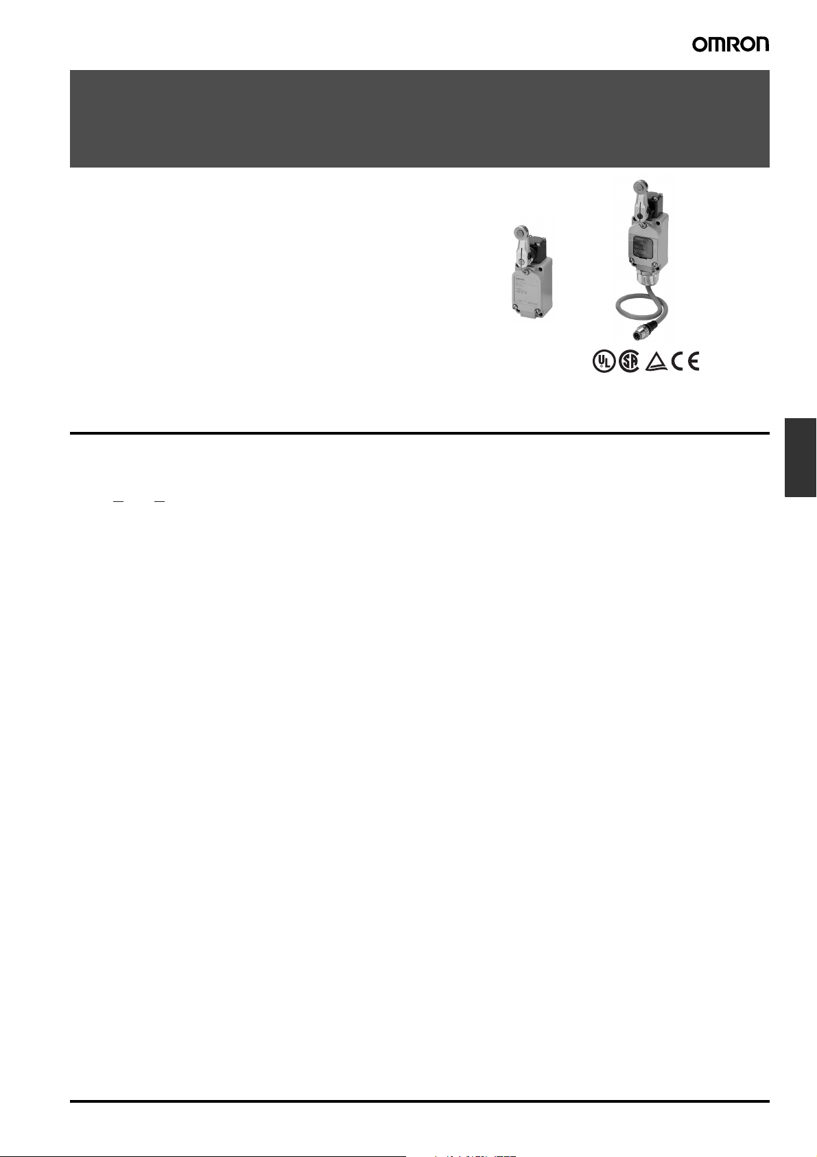
Long-life Two-circuit Limit Switch
WLM@
New Long-life Limit Switches Added to the
Wide Variety of WL Models
• Improved resistance to abrasion and smoother movement in the
head section means that a mechanical life of 30,000,000 operations minimum is now a reality.
• Wiring and replacement for maintenance purposes are easy
done.
• Fluorescent indicators improve visibility when setting stroke
zones.
Model Number Structure
■ Model Number Legend
WLM@-LD@
1 2
1. Actuators
CA2: Roller lever: Standard
GCA2: Roller lever: High-precision
H2: Roller lever: Overtravel, general-purpose
G2: Roller lever: Overtravel, high-sensitivity
2. Wiring Specifications
Blank: Screw terminal: G1/2 conduit
K13A: Direct-wired connector: 2-core, AC
K13: Direct-wired connector: 2-core, DC
K43A: Direct-wired connector: 4-core, AC
K43: Direct-wired connector: 4-core, DC
-M1J: Pre-wired connector: 2-core, DC (See note.)
-AGJ03: Pre-wired connector: 4-core, AC (See note.)
-DGJ03: Pre-wired connector: 4-core, DC (See note.)
Note: With 0.3-m cable attached.
Limit
Switches
Long-life Two-circuit Limit Switch WLM@ F-99
Ordering Information
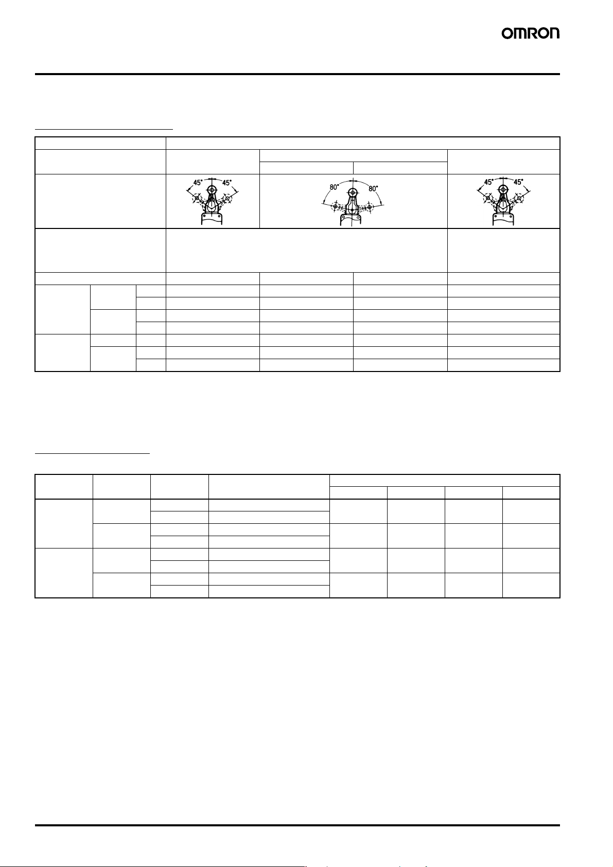
■ List of Models
Roller Lever with LED
Item Model
Type Standard Overtravel High-precision
General-purpose High-sensitivity
Overall movement
Features One-side operation not possible.
Head can be mounted in any of the four directions.
(See note 3.)
Screw terminal WLMCA2-LD WLMH2-LD WLMG2-LD WLMGCA2-LD
Direct-wired
connector
Pre-wired
connector
(See note 2.)
Note: 1. The default setting is light-ON when not operating (NO connection). To switch to light-ON when operating, simply rotate the lamp holder
2. 0.3-m cable attached.
3. One-side operation possible means that, by changing the direction of the operational plunger, one of three operating directions can be
2-core AC WLMCA2-LDK13A WLMH2-LDK13A WLMG2-LDK13A WLMGCA2-LDK13A
DC WLMCA2-LDK13 WLMH2-LDK13 WLMG2-LDK13 WLMGCA2-LDK13
4-core AC WLMCA2-LDK43A WLMH2-LDK43A WLMG2-LDK43A WLMGCA2-LDK43A
DC WLMCA2-LDK43 WLMH2-LDK43 WLMG2-LDK43 WLMGCA2-LDK43
2-core DC WLMCA2-LD-M1J WLMH2-LD-M1J WLMG2-LD-M1J WLMGCA2-LD-M1J
4-core AC WLMCA2-LD-AGJ03 WLMH2-LD-AGJ03 WLMG2-LD-AGJ03 WLMGCA2-LD-AGJ03
DC WLMCA2-LD-DGJ03 WLMH2-LD-DGJ03 WLMG2-LD-DGJ03 WLMGCA2-LD-DGJ03
by 180°. Contact your OMRON representative for details on the 2-core models.
selected. One-side operation not possible means that only operation on both sides is possible. See page 106 for details.
One-side operation possible.
Head can be mounted in any
of the four directions.
(See note 3.)
Applicable Cables
Use the Cables listed below with the Limit Switch with Connector.
Voltage Core wires Cable length Model Connection wires
1234
AC 2 2 m XS2F-A421-DB0-A --- --- Brown Blue
5 m XS2F-A421-GB0-A
4 2 m XS2F-A421-D90-A Brown White Blue Black
5 m XS2F-A421-G90-A
DC 2 2 m XS2F-D421-DD0 --- --- Blue Brown
5 m XS2F-D421-GD0
4 2 m XS2F-D421-D80-A Brown White Blue Black
5 m XS2F-D421-G80-A
F-100 Long-life Two-circuit Limit Switch WLM@
Specifications
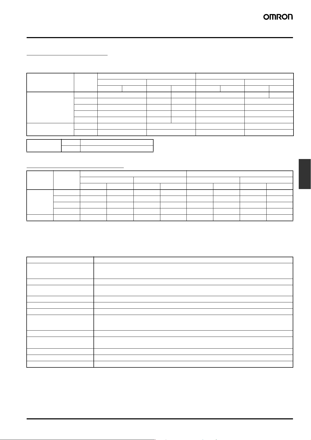
■ Ratings
General-purpose Ratings
Refer to these ratings before using the product.
Screw Terminal Models
Model Rated
Standard, overtravel
(except high-sensitivity),
and high-precision
Overtravel
(High-sensitivity)
Inrush current NC 30 A max. (15 A max. (See note))
NO 20 A max. (10 A max. (See note))
Note: Only for high-sensitivity overtravel models.
voltage
115 VAC 10 3 1.5 10 5 2.5
12 VDC 10 6 3 10 6
24 VDC 6 4 3 6 4
48 VDC 3 2 1.5 3 2
115 VDC 0.8 0.2 0.2 0.8 0.2
115 VAC 5 --- --- --115 VDC 0.4 --- --- ---
Resistive load Lamp load Inductive load Motor load
NC NO NC NO NC NO NC NO
Direct-wired/Pre-wired Models
Model Rated
DC12 VDC33333333
AC 115 VAC 3 3 3 1.5 3 3 3 2.5
Note: 1. The above figures are for standard currents.
2. Inductive loads have a power factor of 0.4 min. (AC) and a time constant of 7 ms max. (DC).
3. Lamp load has an inrush current of 10 times the steady-state current.
4. Motor load has an inrush current of 6 times the steady-state current.
voltage
24 VDC33333333
48 VDC33333333
115 VDC 0.8 0.8 0.2 0.2 0.8 0.8 0.2 0.2
Resistive load Lamp load Inductive load Motor load
NC NO NC NO NC NO NC NO
■ Characteristics
Degree of protection IP67
Durability (See note 2.) Mechanical: 30,000,000 operations min. (10 mA at 24 VDC, resistive load)
Operating speed 1 mm to 1 m/s (for WLMCA2)
Operating frequency Mechanical: 120 operations/minute
Rated frequency 50/60 Hz
Insulation resistance 100 MΩ min. (at 500 VDC)
Contact resistance 25 mΩ max. (initial value)
Dielectric strength 1,000 VAC, 50/60 Hz for 1 min between non-continuous terminals. (Except connector models.)
Vibration resistance 10 to 55 Hz, 1.5-mm double amplitude
Shock resistance
Ambient temperature Operating: –10°C to 80°C (with no icing)
Ambient humidity Operating: 95% max.
Weight Approx. 275 g (for WLMCA2)
Note: 1. The figures in parentheses for dielectric strength, are those for overtravel (high-sensitivity) or connector models.
2. The values are calculated at an operating temperature of 5°C to 35°C, and an operating humidity of 40% to 70%. Contact your OMRON
sales representative for more detailed information on other operating environments.
Electrical: 750,000 operations min. (10 A at 115 VAC, resistive load),
Electrical: 30 operations/minute
2,200 VAC (1,500 V), 50/60 Hz for 1 min between non-current-carrying metal part and ground.
2,200 VAC (1,500 V), 50/60 Hz for 1 min between each terminal and non-current-carrying metal part.
Destruction: 1,000 m/s
Malfunction: 300 m/s
Non-inductive load Inductive load
Non-inductive load Inductive load
but for high-precision models: 500,000 operations min. (10 A at 115 VAC, resistive load)
2
min.
2
min.
Limit
Switches
Long-life Two-circuit Limit Switch WLM@ F-101

■ Operating Characteristics
Operating characteristics WLMCA2-LD@
OF max. 9.81 N 9.81 N 9.81 N 13.34 N
RF min. 0.98 N 0.98 N 0.98 N 1.47 N
PT
OT min. 30° 55° 65° 40°
MD max. 12° 12° 7° 3°
Standard models
15±5
°
WLMH2-LD@
Overtravel models
(general-purpose)
15±5
°
WLMG2-LD@
Overtravel models
(high-sensitivity)
+2°
10
−1°
WLMGCA2-LD@
High-precision models
+2°
5
−0°
■ Contact Form
Screw Terminal Models
WLM@-LD
Lamp-equipped: Light-ON when not operating
Internal circuit
Built-in switch
Direct-wired Connector/Pre-wired Connector Models
AC Models: WLM@-LD@@
Lamp-equipped: Light-ON when not operating (See note.)
AC model DC model
Internal circuit
Built-in switch
Pin No.
2-core
4-core
Note: Light-ON when not operating means that the lamp remains lit when the actuator is free, and goes out when the Limit Switch contacts (NO)
close when the actuator rotates or is pushed down.
Pin No.
2-core
4-core
Internal circuit
Built-in switch
F-102 Long-life Two-circuit Limit Switch WLM@

Engineering Data
■ Electrical Durability: cosφ = 1
Operating temperature: 5°C to 30°C
Operating humidity: 40% to 70%
Operating frequency: 30 operations/min
cosφ = 1
125 VAC
250 VAC
operations)
4
480 VAC
Durability (x 10
Switching current (mA)
■ Lamp-equipped Models
The operating status of the Switch can be checked using a neon
lamp of LED indictor.
Circuit checks and troubleshooting errors are easy done.
Light emitting diode (LED)
Lamp holder
Operation
indicator
window
The built-in switch’s terminal screws are used to connect the lamp
terminal (indicator cover). Since the connection spring (coil spring) is
used for this connection, it will not be necessary to connect to the
lamp terminal. When a ground terminal is provided however, lead
wire method must be used.
WL-LD has a built-in rectifier stack, so it will not be necessary to
change the polarity.
The indicator cover is molded from diecast aluminum and has outstanding sealing properties. Furthermore, regardless of whether the
power is connected or not, the operating status is shown (operating
or not operating), and indicators can be switched from light-ON when
operating and light-ON when not operating, by simply rotating the
lamp holder by 180°.
The lamp-equipped models are ideal in locations using a conveyor
belt where items need to be checked, or locations that are difficult to
inspect for faults.
Contact spring
Light-ON when Operating
LED at top
Light-ON when Not Operating
LED at bottom
Indicator Lamp and Load Operation
When the indicator lamp is set to light-ON when operating, connect
the load on the NC side, and set so that the load turns ON when the
actuator is free.
When the indicator lamp is set to light-ON when not operating, connect the load on the NO side, and set so that the load turns ON when
the actuator is pushed down.
Light-ON when Operating
When the Switch’s contacts and the internal circuit of the lamp holder
are connected in parallel, there is large resistance from the internal
circuit, so the current will flow through the Switch’s contacts and the
load will turn ON.
When the contacts and the internal circuit are separated, only a
small voltage, enough to light the indicator lamp will flow to the lamp,
but the load will not turn ON.
Operation
LIght-ON
when
operating
(See note 1.)
Light-ON
when not
operating
(See note 2.)
WL-LD
WL-LD
Power supply
Built-in switch
Load
Internal circuit
Power supply
Internal circuit
Load
Limit
Switches
Built-in switch
Note: 1. Light-ON when operating means that the lamp lights when
the Limit Switch contacts (NC) release, or when the actuator
rotates or is pushed down.
2. Light-ON when not operating means the lamp remains lit
when the actuator is free, or when the Limit Switch contacts
(NO) close when the actuator rotates or is pushed down.
Long-life Two-circuit Limit Switch WLM@ F-103

Models/Ratings
Operating
characteristics
LED 10 to
Note: 1. In the model number, @ indicates the actuator number. For
2. The default setting is “light-ON when not operating.” Turn the
Maximum
rated voltage
115 VAC, DC
Leakage
current
Approx. 1 mA WL@-LD
Lamp-
equipped
Switch
(See note 1.)
Lamp-
equipped
cover only
WL-LD
example, MCA2, etc.
lamp holder by 180° to change the setting to “light-ON when
operating.”
Nomenclature
Internal Circuits
WL-LD
Contact spring
Zener
diode
Rectifier stack
Resistance
Constant current diode
Light-emitting diode (LED)
Release Plunger
Hardening method changed for greater abrasion resistance.
Standard Model Long-life Model
Sintered
alloy
Head
The Head can be mounted in any of the
four directions by removing the screws at
the four corners of the Head.
Shaft Section Seal
By fitting a double seal consisting of an oil seal
and an X-ring to the rotary shaft, even greater
sealing properties are achieved.
Standard Model Long-life Model
O-ring
Smoother Movement
A grease holder is provided on the shaft to
prevent the grease from running out.
Standard Model
Stainless steel
+
Hardening
Oil seal X-ring
Head
Mounting
Screws
Set Position Marker Plate
The set position is easy to view. The stroke is
indicated in fluorescent color that is visible from
the slit in the rubber cap.
Standard Model Long-life Model
Requires maintenance
(excessive overtravel)
Proper range
Requires maintenance (insufficient overtravel)
Proper range
Requires maintenance (excessive overtravel)
Roller
The roller is made of self-lubricating stainless sintered
and boasts high resistance to wear.
Lever
The lever forged of anti-corrosive aluminium alloy
features high corrosion resistance and outstanding
ruggedness. With roller lever models, the actuator
position can be set anywhere within 360°. (The lever
cannot be mounted in the opposite direction.)
Operational Plunger (See note.)
Fluorescent paint
Cover Seal
Long-life Model
Grease holder
Smooth movement is achieved using
olefin grease. (Standard models use
molybdenum disulfide grease.)
Bearing
The bearing smooths the plunger movement.
Built-in Switch
Built-in switch with SPST-NO+NC contact form.
Conduit Opening
In addition to level screws which use G 1/2 tube, directwired and pre-wired connectors have been added.
By using a packing seal as the cover seal, an
optimum squeeze can be obtained and high sealing
properties are assured as well.
Terminal Screws
Four, M4 screws
Cover
Separator
The separator has outstanding insulation
properties and prevents the generation of any
gases which may corrode the internal parts.
Cover Mounting Screw
A Phillips screw is used to ensure ease of use.
Note: By changing the direction of the operational plunger, any one of the three operational directions (both sides, left, or right) can be selected.
(Only applicable to the WLMGCA2-@.)
F-104 Long-life Two-circuit Limit Switch WLM@

Dimensions
Rotating Lever Models: Standard
Screw Terminals
WLM@-LD
17.5 dia. × 7 (See note)
38R
14.7
58.7±0.2
5
(15.1)
(4.9)
Pre-wired Connectors
WLM@-LD@
17.5 dia. × 7 (See note)
38R
14.7
58.7±0.2
30.2
40±0.7
±
0.2
Four, M3.5
(length: 26.5)
M5 × 12
Allen-head
bolt
+0.2
Four ,5.2
0
holes
Rubber cap
Three, M4 × 13
Lamp cover
JIS B0202 G1/2
Effective thread:
4 threads min.
Four, M3.5
(length: 26.5)
M5 × 12
Allen-head
bolt
+0.2
Four, 5.2
0
Rubber cap
Three, M4 × 13
dia.
dia.
holes
60 max.
53±1.5
41.5±1.5
40±1.5
42 max.
53.2±0.8
60 max.
53±1.5
41.5±1.5
25.4
21.6
29.2
35
40±1.5
25.4
13.1
12.7
Four, M6
Depth: 15 min.
±
1.2
13.1
12.7
25.4
68.7
25.4
68.7
Direct-wired Connectors
WLM@-LD@
14.7
58.7±0.2
5
(15.1)
(4.9)
Note: Stainless steel rollerNote: Stainless steel roller
17.5 dia. × 5 (See note)
38R
Four, M3.5
(length: 26.5)
Four ,5.2
Rubber cap
Three, M4 × 13
Lamp cover
12.5
30.2
40±0.7
±
0.2
SC-2FD
M12 × 1
JIS B0202 G1/2
Effective thread:
4 threads min.
M5 × 12
Allen-head
bolt
+0.2
dia.
0
holes
60 max.
53±1.5
41.5±1.5
40±1.5
29.2
42 max.
53.2±0.8
35
25.4
21.6
±
13.1
1.2
12.7
25.4
68.7
Four, M6
Depth: 15 min.
Limit
Switches
(25)
5
Four, M6
Depth: 15 min.
XS2H-D421
Lamp cover
300±50
52
(15.1)
(4.9)
30.2
40±0.7
±
0.2
53.2±0.8
29.2
35
42 max.
21.6
6 dia.
±
1.2
Note: Stainless steel roller
Note: Unless otherwise indicated, a tolerance of ±0.4 mm applies to all dimensions.
Long-life Two-circuit Limit Switch WLM@ F-105

Accessories
Cable
Straight
5 dia.
5 dia.
6 dia.
14.9 dia.
DC
AC
Installation
Item Appropriate model/actuator Details
Changing the installation position of
the actuator
By loosening the Allen-head bolt on the
actuator lever, the position of the actuator can be set anywhere within 360°.
With Lamp-equipped Switches, the actuator lever comes in contact with the
top of the lamp cover, so use caution
when rotating and setting the lever.
Installing the roller on the inside
By installing the roller lever in the opposite direction, the roller can be installed
on the inside. (Set so that operation can
be completed within a 180° level
range.)
Changing the orientation of the head
By removing the screws in the four corners of the Head, the Head can be set
in any of the four directions. Be sure to
change the plunger for internal operations at the same time. (The operational
plunger does not need to be changed
on overtravel general-purpose and
overtravel high-sensitivity models.)
Roller Levers: WLMCA2@, WLMH2@,
WLMG2@, WLMGCA2@
Roller Levers: WLMCA2@, WLMH2@,
WLMG2@, WLMGCA2@
Roller Levers: WLMCA2@, WLMH2@,
WLMG2@, WLMGCA2@
Loosen the
Allen head bolt
Head
Loosen the M5 × 12 bolt, set the
actuator's position and then
tighten the bolt again.
Loosen the screws
Head
Loosen the
screws
Changing the operating direction
Roller Levers: WLMGCA2@
By removing the Head on models which
can operate on one-side, and then
changing the direction of the operational plunger, one of three operating directions can be selected.
The tightening torque for the screws on
the Head is 0.78 to 0.88 N·m.
F-106 Long-life Two-circuit Limit Switch WLM@
The output of the
Switch will be changed,
regardless of which
direction the lever is
pushed.
Operating
Operation in both
directions
Not operating Not operating
Operating Operating Operating
Clockwise operation Anti-clockwise
The output of the
Switch will only be
changed when the lever
is pushed in one
direction.
Operational
plunger
operation

Precautions
■ Correct Use
When wiring terminal screws, use M4 round crimp terminals and
tighten screws to the recommended torque. Wiring with broken
wires, or the incorrect crimp terminals, or not tightening screws to the
recommended torque can lead to short-circuits, leakage current, and
fire.
When performing internal wiring there is a chance of short-circuit,
leakage current, or fire, so be sure to protect the inside of the Switch
from splashes of oil or water, corrosive gases, and cutting powder.
Using an inappropriate connector or assembling Switches incorrectly
(assembly, tightening torque) can result in malfunction, leakage current, or fire, so be sure to read the instruction manual thoroughly
beforehand.
Even when the connector is assembled and set correctly, the end of
the cable and the inside of the Switch may come in contact. This can
lead to malfunction, leakage current, or fire, so be sure to protect the
end of the cable from splashes of oil or water and corrosive gases.
Environmental Precautions
When the Switch is used in locations subject to splashes of water or
oil, the material of the seal, which ensures the sealing properties of
the Switch, may undergo changes in shape and quality. This is due to
deterioration (including expansion and contraction), and may result in
reduced performance, ineffective return, and ineffective sealing
(leading to ineffective contact, insulation, leakage current, and fire).
Confirm the possible effects of the operating environment on the
Switch before use.
Tightening Torque
If screws are too loose they can lead to an early malfunction of the
Switch, so ensure that all screws are tightened using the correct
torque.
No. Type Torque
1 Head mounting screw 0.78 to 0.88 N·m
2 Cover mounting screw 1.18 to 1.37 N·m
3 Allen-head bolt
(for securing the lever)
4 Terminal screw 0.59 to 0.78 N·m
5 Connector 1.77 to 2.16 N·m
6 Main Unit screws 4.90 to 5.88 N·m
4.90 to 5.88 N·m
Limit
Switches
Built-in Switch
Do not replace the built-in switch. If the position of the insulation
sheet moves (separator), the insulation may become ineffective.
In particular, when changing the direction of the Head, make sure
that all screws are tightened again to the correct torque. Do not allow
foreign objects to fall into the Switch.
Installing the Switch
To install the Switch, make a mounting panel, as shown in the following diagram, and tighten screws using the correct torque.
+0.2
Four, 5.2
dia. mounting holes or M5 taps
0
Connectors
Either the easy-to-use Allen-head nut or the SC Connector can be
used as connectors. To ensure high-sealing properties, use the SC
Connector. (SC-1M to -5M and others.)
Long-life Two-circuit Limit Switch WLM@ F-107

Wiring
Use 1.25-mm lead wires and M4-insulation covered crimp terminals
for wiring.
Crimp Terminal External Dimensions
D dia.
dz dia. 4.3
D dia. 4.5
B: 8.5
L: 21.0
F: 7.8
l: 9.0 (mm)
Wiring Method
Switch Box Section
dz dia.
Operation Set Position
There is a set position marker slit on the rubber cap of the head.
After operation, set the slit on the rubber cap so that the fluorescent
color on the shaft section can be seen.
Terminal Plate
By using a short circuit plate, as shown in the following diagram, the
Switch can be fabricated into a single-polarity double-break model.
When ordering specify WL Terminal-Plate (IWPA01).
.
3R
9+0.2
16±0.15
2R
Ground terminal
NO terminal
NC terminal
Note: Ground terminals are not installed on the standard models.
2.1R
t = 0.6 Copper plate
ALL DIMENSIONS SHOWN ARE IN MILLIMETERS.
To convert millimeters into inches, multiply by 0.03937. To convert grams into ounces, multiply by 0.03527.
Cat. No. C112-E1-02
In the interest of product improvement, specifications are subject to change without notice.
F-108 Long-life Two-circuit Limit Switch WLM@
 Loading...