

Page 1
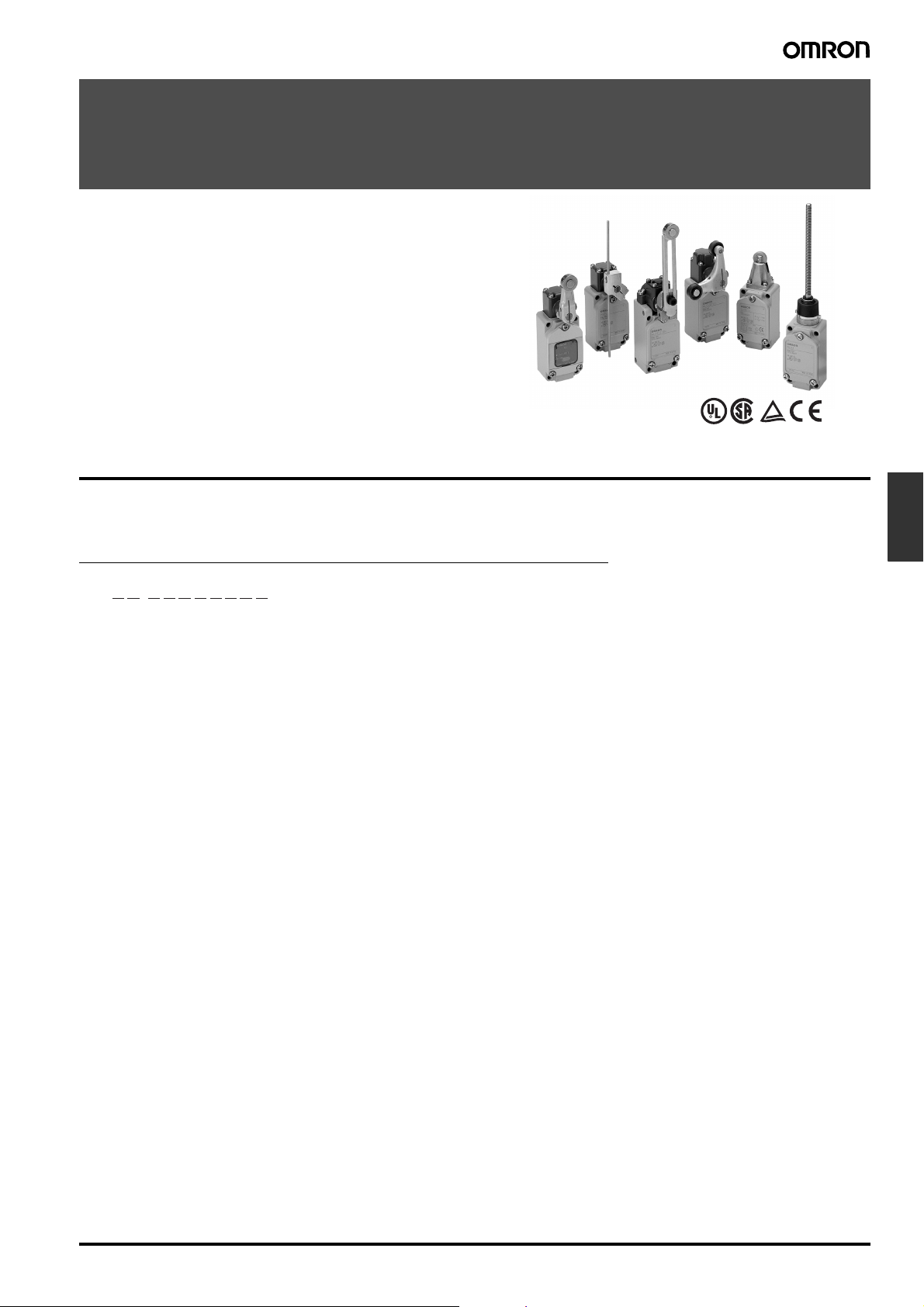
Two-circuit Limit Switch
WL
Wide Selection of Two-circuit Limit Switches
• A wide selection of models are available, including the overtravel models with greater OT, lamp-equipped models for checking
operation, low-temperature and heat-resistant models, and microload models.
• Microload models are added to the product lineup.
• Meets EN/IEC standards (only Switches with ground terminals).
• Switches with ground terminals have the CE marking.
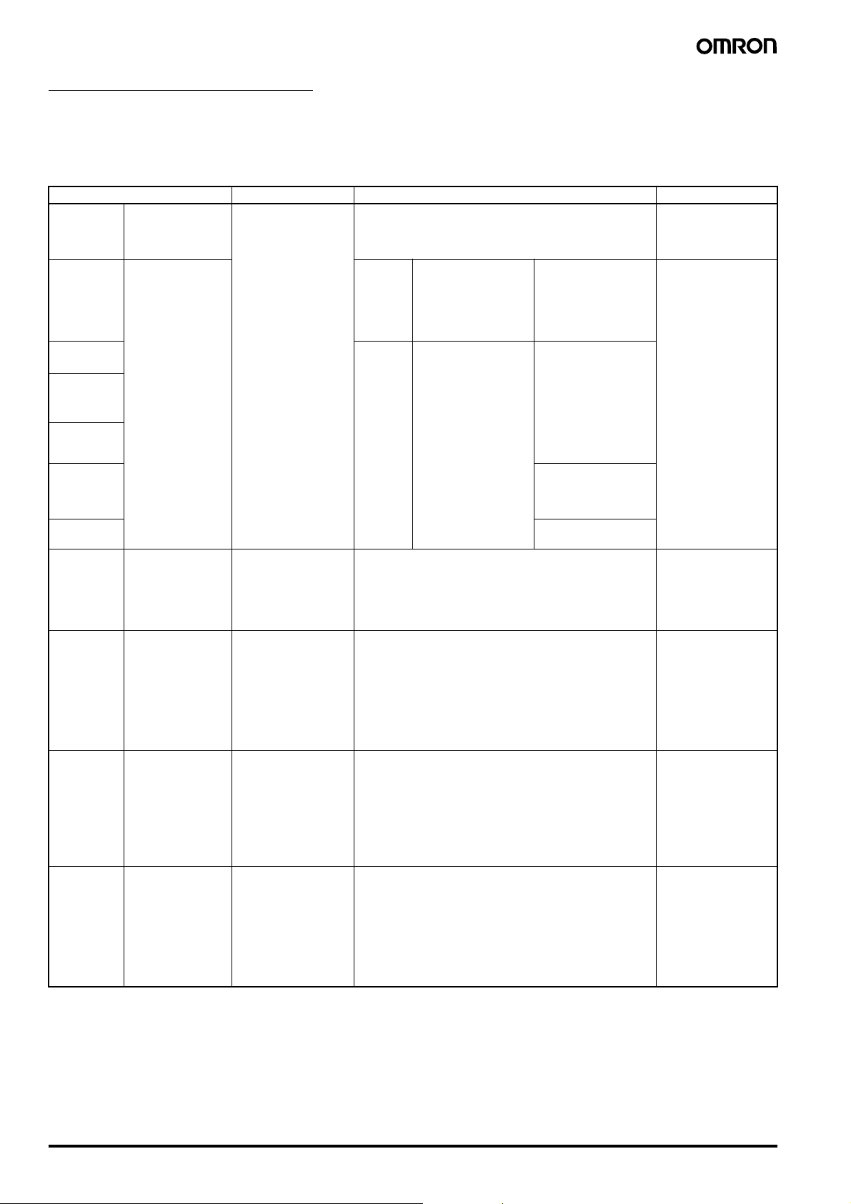
Model Number Structure
■ Model Number Legend
General-purpose Models/Environment-resistant Models
WL@@-@@@@@@@@
1 2 3 4 5 6 7 8 9 10
1. Electrical Rating
Blank: Standard
01: Micro
2. Actuator and Head Specifications
Symbol Actuator type Switches without levers
CA2 Roller lever: Standard model (R38) WLRCA2
CA2-7 Roller lever: Standard, standard model (R50) WLRCA2
CA2-8 Roller lever: Standard, standard model (R63) WLRCA2
H2 Roller lever: Overtravel, general-purpose model, 80° WLRH2
G2 Roller lever: Overtravel, high-sensitivity, 80° WLRG2
CA2-2N Roller lever: Overtravel, 90° WLRCA2-2N
GCA2 Roller lever: High-precision WLRGCA2
CA12 Adjustable roller lever: Standard WLRCA2
H12 Adjustable roller lever: Overtravel, general-purpose model, 80° WLRH2
G12 Adjustable roller lever: Overtravel, high-sensitivity, 80° WLRG2
CA12-2N Adjustable roller lever: Overtravel, 90° WLRCA2-2N
CL Adjustable rod lever: Standard WLRCL
HL Adjustable rod lever: Overtravel, general-purpose model, 80°, 25 to 140 mm WLRH2
HLAL4 Adjustable rod lever: Overtravel, general-purpose model, 80°, 350 to 380 mm WLRH2
GL Adjustable rod lever: Overtravel, high-sensitivity, 80°, 25 to 140 mm WLRG2
CL-2N Adjustable rod lever: Overtravel, 90°, 25 to 140 mm WLRCA2-2N
HAL5 Rod spring lever: Protective, Overtravel, general-purpose model, 80° WLRH2
CA32-41 Fork lever lock: Protective, WL-5A100 WLRCA32
CA32-42 Fork lever lock: Protective, WL-5A102 WLRCA32
CA32-43 Fork lever lock: Protective, WL-5A104 WLRCA32
D Plunger: Top plunger --D2 Plunger: Top-roller plunger --D28 Plunger: Sealed top-roller plunger --D3 Plunger: Top-ball plunger --SD Plunger: Horizontal plunger ---
Limit
Switches
Two-circuit Limit Switch WL F-57
Page 2

Symbol Actuator type Switches without levers
SD2 Plunger: Horizontal-roller plunger --SD3 Plunger: Horizontal-ball plunger --NJ Flexible rod: Coil spring --NJ-30 Flexible rod: Coil spring, multi-wire --NJ-2 Flexible rod: Coil spring, resin rod --NJ-S2 Flexible rod: Steel wire ---
3. Environment-resistant Model Specifications
Blank: Standard
RP: Corrosion-proof (See note 1.)
P1: Weather-resistant (See note 1.)
4. Built-in Switch Specifications
Blank: General-purpose built-in switch
55: Hermetically-sealed built-in switch (See note 1.)
5. Temperature Specifications
Blank: Standard: –10°C to 80°C
TH: Heat-resistive: 5°C to 120°C (See note 1.)
TC: Low temperature: –40°C to 40°C (See note 1.)
6. Special Hermetic Model Specifications
Blank: No cables or molding
139: General-purpose built-in switch with cables attached and molded conduit opening and cover (cover cannot be removed).
(See note 1.)
140: Airtight built-in switch with cables attached and molded conduit opening, cover, and case cover (cover cannot be removed).
(See note 1.)
141: Airtight built-in switch with cables attached and molded conduit opening, cover, and case cover (cover cannot be removed).
The Head opening is created to protect it from cutting powder. (See note 1.)
145: Airtight built-in switch with cables attached and molded conduit opening, cover, and case cover (cover cannot be removed, Head
can be mounted in any of 4 directions).
The Head opening is created to protect it from cutting powder. (See note 1.)
RP40: Airtight built-in switch with cables attached, SC Connector can be used, molded conduit opening, cover, and case cover
(cover cannot be removed, Head direction can be changed). (See note 1.)
RP60: Airtight built-in switch with cables attached, fluorine rubber-molded conduit opening, cover, and case cover
(cover cannot be removed, Head direction cannot be changed). (See note 1.)
7. Conduit Size, Ground Terminal Specifications (See note 2.)
Blank: G
G1: G
1
/
2
1
/
2
Without ground terminal
With ground terminal
G: Pg13.5 With ground terminal
Y: M20 With ground terminal
TS:
1
/2-14NPT With ground terminal
8. Indicator Type
Element Voltage Leakage Current
LE: Neon lamp 125 VAC Approx. 0.6 mA
250 VAC Approx. 1.9 mA
LD: LED 10 to 115 VAC/VDC Approx. 0.5 mA
9. Lamp Wiring
2: NC connection: Light-ON when operating
3: NO connection: Light-ON when not operating
10.Lever Type
Blank: Standard lever
A: Double nut lever
Note: 1. For information on applicable models, see page 60.
2. Switches with ground terminals meet EN/IEC standards (and have the CE marking).
Ground Terminal Models
WL -
12
F-58 Two-circuit Limit Switch WL
1: Type of actuator
2: Conduit opening size
The models differ depending on the size of the case’s conduit thread.
Model Conduit opening size
G1
G
1
/
2
G Pg 13.5
YM20
TS
1
/2-14NPT
Page 3
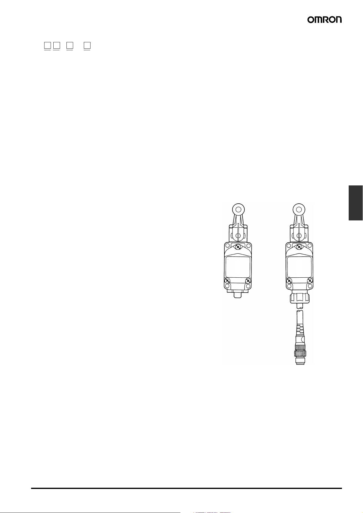
Sensor I/O Connector Models
WL - LD
12 34
1. Electrical Rating
Blank: Standard
01: Microload
2. Actuator Type
CA2: Roller lever: Standard
GCA2: Roller lever: High-precision
H2: Roller lever: Overtravel, general-purpose
G2: Roller lever: Overtravel, high-sensitivity
D2: Plunger: Top-roller plunger
D28: Plunger: Sealed top-roller plunger
3. Built-in Switch Type
Blank: Standard
55: Hermetically sealed
4. Wiring Specifications
K13A: Direct-wired Connector
K13: Direct-wired Connector
K43A: Direct-wired Connector (4-core: AC)
K43: Direct-wired Connector (4-core: DC)
-M1J: Pre-wired Connector (See note 2.)
-M1GJ: Pre-wired Connector (See note 2.)
(See note 1.) (2-core: DC, NO wiring, connector pins No. 1, 4)
-M1JB: Pre-wired Connector (See note 2.)
(See note 1.) (2-core: DC, NC wiring, connector pins No. 3, 2)
-AGJ03: Pre-wired Connector (See note 2.) (4-core, AC)
-DGJ03: Pre-wired Connector (See note 2.) (4-core, DC)
(See note 1.)
-DK1EJ03: Pre-wired Connector (See note 2.)
(See note 1.) (3-core: DC, NO wiring, connector pins No. 2, 3, 4)
Note: 1. Models with pre-wired connectors and DC specifications
2. With 0.3-m cable attached.
Direct-wired Connector
(2-core: AC, NO wiring, connector pins No. 3, 4)
(2-core: DC, NO wiring, connector pins No. 3, 4)
(2-core: DC, NO wiring, connector pins No. 3, 4)
have EN/IEC approval.
Pre-wired Connector
Limit
Switches
Two-circuit Limit Switch WL F-59
Page 4
Spatter-prevention Models
WL - S
12 34 5
1. Electrical Rating
Blank: Standard
01: Microload
2. Actuator Type
CA2: Roller lever: Standard model
GCA2: Roller lever: High-precision model
H2: Roller lever: Overtravel, general-purpose model
G2: Roller lever: Overtravel, high-sensitivity model
D28: Plunger: Sealed top-roller plunger
3. Built-in Switch Type
Blank: Standard
55: Hermetically sealed
Ordering Information
■ Classification
4. Indicator Lamp
Blank: None
LD: LED indicator lamp (AC/DC common)
LE: Neon Lamp
5. Wiring Specifications
-M1J-1: Pre-wired Connector (See note.)
(2-core: DC, NO wiring, connector pins No. 3, 4)
-M1GJ-1: Pre-wired Connector (See note.)
(2-core: DC, NO wiring, connector pins No. 1, 4)
-DGJS03: Pre-wired Connector (See note.) (4 core, DC)
Note: With 0.3-m cable attached.
Specifications Standard Overtravel High-
Actuators Roller lever Yes Yes Yes Five models: Roller lever, adjustable roller le-
Plunger Yes --- --- Six models: Top plunger, top-roller plunger,
Flexible rod Yes --- --- Two models: coil spring and steel wire.
Load/
contact
Environment-resistant
models
(See
note 3.)
Standard load SPST-NO/
Microload SPST-NO/
Airtight-seal WL@-55 Yes (Cannot be used with heat-resistive
Hermet-
ic seal
Spatter-prevention WL@-S Yes To improve spatter prevention during welding,
Molded
terminals
Anti-coolant
SPST-NC
type
SPST-NC
type
WL@-139 Lead wires are attached.
WL@-140
WL@-141
WL@-145
WL@-RP40 The connector can be removed, so it is possi-
WL@-RP60 Rubber parts are made from fluorine rubber.
Yes Standard models use a two-circuit double-
Yes Specifications include gold-plated contacts.
and low-temperature models.)
precision
ver, adjustable rod lever, fork lever lock, rod
spring lever.
top-ball plunger, horizontal plunger, horizontal-roller plunger, horizontal-ball plunger.
break switch.
Uses an airtight-sealed built-in switch. 66, 76
The case cover and conduit section are molded from epoxy resin to improve sealing performance.
Lead wires are attached.
The case is filled with epoxy resin, to ensure
high sealing performance.
The Head opening is protected from cutting
powder. (WL@-141 and -145 models)
Only WLG2, WLCA2, and WLGCA2 can be
fabricated. (WL@-141 models.)
ble to use flexible wires in the cable. The
Head can be removed.
The Head cannot be removed.
a heat-resistant resin is used, and screws
and rollers are all made from stainless steel.
Features Page
77 to
94
62 to
64
69, 73
to 75
67, 69,
71, 73,
76, 89
F-60 Two-circuit Limit Switch WL
Page 5
Specifications Standard Overtravel High-
Environment-resistant
models
(See
note 3.)
Lamp-equipped WL@-LE Yes Operating status can be checked at a glance.
Relevant pages Pages 77 to 94 --- ---
Heat-resistive WL@-TH Yes (Cannot be used with airtight, hermet-
Low-temperature WL@-TC Yes (Cannot be used with airtight, hermet-
Corrosion-proof
(See note 4.)
Outdoor specifications
WL@-RP Yes (Cannot be used with lamp-equipped
WL@-P1 ---
WL@-LD Yes
ic, low-temperature, corrosion-proof, or
lamp-equipped models.)
ic, heat-resistive, corrosion-proof, or lampequipped models.)
models.)
(See note 5.)
Ye s
(See note 6.)
precision
To improve heat resistance, silicone rubber is
used for rubber parts and for the built-in
switch.
The operating temperature range is +5°C to
120°C.
To improve low temperature resistance, silicone rubber is used.
The operating temperature range is –40°C to
40°C.
Diecast parts such as the switch box are
made of corrosion-proof aluminum. Rubbersealing parts are made of fluorine rubber and
exposed nuts and screws are made of stainless steel. These all aid in resisting oil, chemicals and adverse weather conditions.
--- Rotary shafts are made of unquenched (i.e.,
untreated) stainless steel to improve corrosion resistance. Exposed nuts and screws
are made of stainless steel and rubber sealing parts of silicone rubber. These factors all
combine to create a product which is resistant
to temperature changes and adverse weather
conditions.
Lit when operating and not lit when not operating.
WL@-LE: 100 VAC/VDC min.
WL@-LD: 115 VAC/VDC min. (Refer to
page 71 for detailed ratings.)
Features Page
66
64, 72,
73, 75,
86
Limit
Switches
Note: 1. Do not expose to extreme changes in temperature.
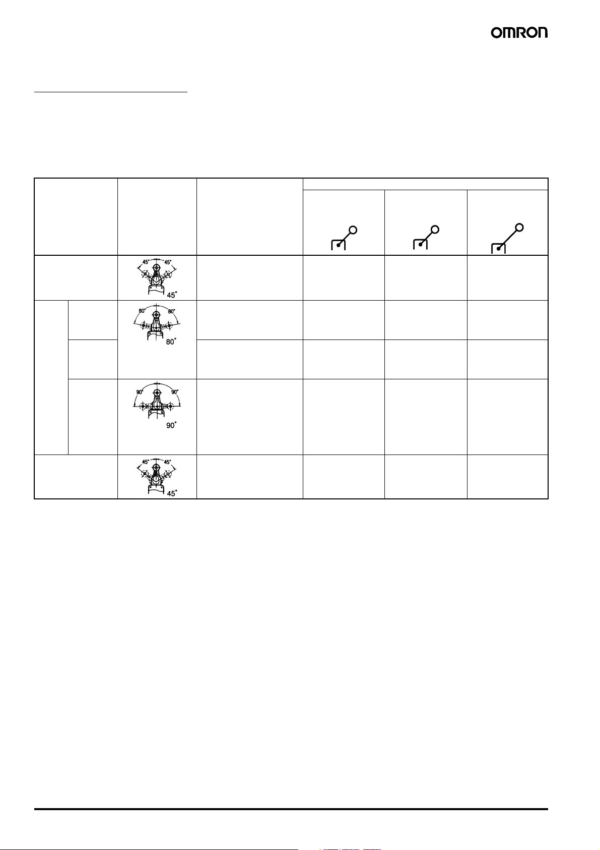
2. Standard Models: Operate on each side at an angle of 45°.
Overtravel Models: Standard and high-sensitivity models operate on each side at an angle of 80°.
High-precision Models: Operate on each side at an angle of 45°.
3. When ordering, add the suffix for the environment-resistant model or indicator specifications required according to the operating environ-
ment and purpose.
4. The overtravel model (-2N Series), fork lever lock model (WLCA32-41 to 44), horizontal plunger (WLSD@) model, heat-resistive model,
low-temperature model, and lamp-equipped model cannot be used with the corrosion-proof model.
5. Outdoor specifications are available for some standard models. Consult your OMRON representative for details.
6. Outdoor specifications are only available for general models and high-sensitivity models.
Possible to set to one-side operation on either side.
Pretravel (PT) is 15°.
Not possible to set to one-side operation.
-2N Series operate on each side at an angle of 90°.
Possible to set to one-side operation on either side.
Possible to set to one-side operation on either side.
Pretravel (PT) is 5°.
Two-circuit Limit Switch WL F-61
Page 6
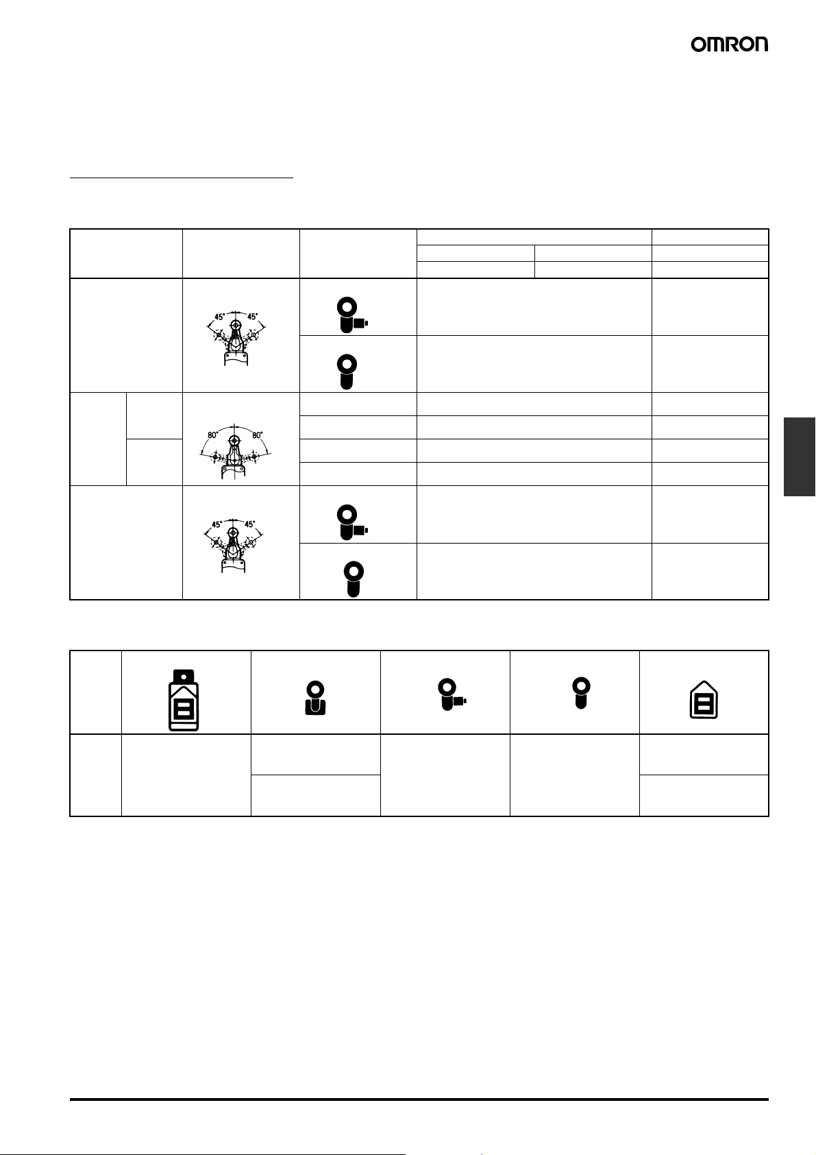
■ List of Models
General-purpose Models
These Limit Switches are two-circuit double-break switches housed in rugged diecast, thus making it an oil-tight, waterproof and dustproof construction (complies with IP67).
In addition to the standard models, microload models are also available.
A wide range of actuators with a range of functions are available; rotating lever, plunger, flexible rod etc.
The rubber material in the standard models is designed to be resistant to water and most oils.
Roller Lever Models: Short, Medium, and Long Lever Models
Type Total travel (TT) Features Actuator (See note 2.)
WL-1A100 Roller
Lever: Short
lever (R38)
WL-1A200 Roller
Lever: Medium
lever (R50)
WL-1A300 Roller
Lever: Long
lever (R63)
Standard One-side operation is possi-
Overtravel
High-precision One-side operation is possi-
Note: 1. For the approved standards file numbers, refer to page 69.
General One-side operation is impos-
High-sensitivity
Side-installation
2. For external dimensions and other information, refer to pages 77 to 94.
3. One-side operation means that three operational directions can be selected electrically, according to the change in direction of the oper-
ating plunger. Those models for which one-side operation is impossible can only operate on both sides. For details, see page 94.
ble. (See note 3.)
Head can be mounted in any
of the four directions.
sible. (See note 3.)
Head can be mounted in any
of the four directions.
One-side operation is possible. (See note 3.)
Head can be mounted in any
of the four directions.
One-side operation is possible. (See note 3.)
Head can be mounted in any
of the two directions. (When
the Head can be mounted
horizontally, the Head can be
mounted in any of the four directions.)
ble. (See note 3.)
Head can be mounted in any
of the four directions.
WLCA2 WLCA2-7 WLCA2-8
WLH2 --- ---
WLG2 --- ---
WLCA2-2N --- ---
WLGCA2 --- ---
F-62 Two-circuit Limit Switch WL
Page 7
Adjustable Roller Levers and Adjustable Rod Levers
Type Total Travel (TT) Features Actuator (See note 2.)
WL-2A100
Adjustable
Roller Lever
WL-4A100
Adjustable Rod
Lever (Adjustable
length: 25 to
140 mm)
WL-3A100
(Adjustable length:
350 to 380 mm)
Standard One-side operation possible. (See note 3.)
Overtrav-elGeneral One-side operation possible. (See note 3.)
High-sensitivity
Side-installation
p
Note: 1. For the approved standards file numbers, refer to page 69.
2. For external dimensions and other information, refer to pages 77 to 94.
3. One-side operation means that three operational directions can be selected electrically, according to the change in direction of the oper-
ating plunger. The operating plunger is set for operation on both sides before delivery. Those models for which one-side operation is impossible can only operate on both sides. For details, see page 94. The operational plunger is factory-set to both sides.
Head can be mounted in any of the four directions.
Head can be mounted in any of the four directions.
One-side operation possible. (See note 3.)
Head can be mounted in any of the four directions.
One-side operation is possible. (See note 3.)
Head can be mounted in any of the two directions.
(When the Head can be mounted horizontally, the
Head can be mounted in any of the four directions.)
WLCA12 ---
--- WLCL (WL-4A100)
WLH12 WLHL (WL-4A100)
WLHAL4 (WL-3A100)
WLG12 WLGL (WL-4A100)
WLCA12-2N WLCL-2N (WL-4A100)
Rod Spring Levers and Fork Lever Locks
Type Total travel (TT) Features Actuator (See note 2.)
WL-3A200 Rod
Spring Lever
Fork Lever Locks:
WL-5A100,
WL-5A102,
WL-5A104
Limit
Switches
Protective Head can be mounted in any of the four directions. --- WLCA32-41
Overtrav-elGeneral One-side operation is possible. (See note 3.)
Head can be mounted in any of the four directions.
Note: 1. For the approved standard file numbers, refer to page 69.
2. For external dimensions and other information, refer to pages 77 to 94.
3. One-side operation means that three operational directions can be selected electrically, according to the change in direction of the oper-
ating plunger. The operating plunger is set for operation on both sides before delivery. Those models for which one-side operation is impossible can only operate on both sides. For details, see page 94. The operational plunger is factory-set to both sides.
4. The fork lever lock is configured so that the dog pushes the lever to reverse the output and this reversed state is maintained even after
the dog continues on. If the dog then pushes the lever from the opposite direction, the lever will return to its original position.
WLHAL5 ---
(WL-5A100)
WLCA32-42
(WL-5A102)
WLCA32-43
(WL-5A104)
Two-circuit Limit Switch WL F-63
Page 8
Standard Plungers
Type Actuators Model
To p W L D
Top Plunger
Top-roller Plunger
Top-ball Plunger
WLD2
WLD28 (See note.)
WLD3
Standard Flexible Rods
Actuators Model
Coil spring
Steel wire
Spring dia. 6.5 WLNJ
Spring dia. 4.8 WLNJ-30
Resin rod dia. 8.0 WLNJ-2
1.0-dia. wire WLNJ-S2
Horizontal WLSD
Horizontal Plunger
Microload Models
Horizontal-roller
Plunger
Horizontal-ball Plunger
Note: Sealed roller.
WLSD2
WLSD3
A series of microload models has also been developed for the configurations outlined on pages 62 to 64. The model numbers become
WL01@. For example, WLCA2 becomes WL01CA2.
Lamp-equipped Models
Operating
characteristics
Neon lamp 125 VAC Approx. 0.6 mA WL@-LE (See note 1.) WL-LE
LED 10 to 115 VAC/VDC Approx. 0.5 mA WL@-LD (See note 1.) WL-LD
Note: 1. In the model number, @ indicates the actuator number. For example, CA2, D, NJ, etc.
2. The default setting is “light-ON when not operating.” Turn the lamp holder by 180° to change the setting to “light-ON when operating.”
Ordering Information
When ordering general-purpose indicator-equipped models insert the specifications number at the end of the basic model number.
E.g.: When a neon lamp is installed in a General-purpose/Standard Roller Lever Switch (WLCA2).
WLCA2
↑↑
Standard Lamp
When ordering indicator-equipped molded terminal models, insert the specifications number at the end of the standard model number.
E.g.: When a Neon Lamp (WL-LE) is installed in a general-purpose molded terminal model (WLCA2-139).
WLCA2-139
↑↑↑
Standard Lamp Lamp 2: NC connection: Light-ON when operating
Note: The indicator cover cannot be replaced on the molded terminals. In all cases the indicator does not light when the load is ON.
Rated voltage Leakage current Lamp-equipped Switch Lamp-equipped cover only
250 VAC Approx. 1.9 mA
LE
specifications
LE 2
specifications wiring 3: NO connection: Light-ON when not operating
F-64 Two-circuit Limit Switch WL
Page 9
Sensor I/O Connector Models
A reduction in the amount of wiring and parts makes maintenance easy and reduced wiring mistakes, in addition it’s already compact size for fitting
into areas of limited space.
Ordering Information
Item Standard Overtravel High sensitivity
Actuators Rotating lever Yes Yes Yes
Plunger Yes --- ---
Load Standard load (SPST-NO/SPST-NC) Yes
Microload (SPST-NO/SPST-NC) Yes
High-precision models WL-@55 Yes
Spatter-prevention models (See note 3.) Yes
Lamp Yes
Note: 1. Standard Models: For standard models only one-side operation at an angle of 45° is possible.
Direct-wired Connectors
Lamp-equipped WL@-LDK13 WL@-LDK43
Double-seal WL@-55LDK13 WL@-55LDK43
Overtravel Models: Only one-side operation at an angle of 80° is possible. One-side operation only is not possible.
High-precision Models: Only one-side operation at an angle of 45° is possible, and pretravel (PT) is 5°, as opposed to 15° for standard
models.
2. For information other than that listed at the above, contact your OMRON representative.
3. The spatter-prevention models are only available as pre-wired connectors.
Note: 1. In the model number, @ indicates the actuator number. For
Type 2-core (NO) 4-core
example, Overtravel Model WLG2
2. The lamp is set to “light-ON when not operating” (NO con-
nection).
-LDK13.
Pre-wired Connectors
Type 2-core (NO) 2-core (NC) 4-core 3-core (NO)
Lamp-equipped WL@-LD-M1J WL@-LD-M1JB WL@-LD-DGJ03 WL@-LD-DK1EJ03
Double-seal WL@-55LD-M1J WL@-55LD-M1JB WL@-55LD-DGJ03 WL@-55LD-DK1EJ03
Note: 1. In the model number, @ indicates the actuator number. For example, Overtravel Model WLG2-LD-M1J.
2. The lamp is set to “light-ON when not operating” (NO connection).
Limit
Switches
Two-circuit Limit Switch WL F-65
Page 10
Environment-resistant Models
Airtight, Hermetic Seal, Low-temperature, Heat-resistive, Corrosion-proof, and Weatherresistant Models
Using the general-purpose model, six types of environment-resistant models can be created to meet a variety of difficult operating conditions. Select the model most appropriate to your operating environment.
Type Usage Environment-resistant construction Appropriate models
WL@-55 Airtight seal For use in locations
WL@-139 Hermetic seal
(molded terminals
and anti-coolant
models)
WL@-140 Hermeti-
WL@-141
WL@-145
WL@-RP40 The connector can be
WL@-RP60 Rubber parts are made
WL@-TC Low-temperature Can be used at a tem-
WL@-TH Heat-resistive Can be used in tem-
WL@-RP Corrosion-proof For use in locations
WL@-P1 Outdoor specifica-
tions
Note: 1. Consult your OMRON representative for the microload WL01@ models.
2. Use the SC Connector for the conduit opening.
3. The actuator can be created using the standard model.
4. The actuator can be created using the standard model. For WL-@141 and -145, only WLG2, WLCA2, WLGCA2, and WLH2 can be used.
subject to splashes of
water and anti-coolant
perature of
–40°C (The operating
temperature range is
–40°C to 40°C), but
cannot withstand icing.
peratures of 120°C
(The operating temperature range is 5°C to
120°C).
subject to corrosive
gases and chemicals.
For use in parking lots
and other such outdoor
locations.
Uses the W-10FB3-55 Airtight Built-in Switch. (See note 2.) All models except the
Generalpurpose
built-in
switch
callysealed
built-in
switch
Uses the general-purpose built-in switch.
Silicone rubber is used for rubber parts such as the O-ring,
gasket, etc.
Uses a special built-in switch made from heat-resistant resin.
Silicone rubber is used for rubber parts such as the O-ring,
gasket etc.
Diecast parts such as the switch box are made of corrosionproof aluminum.
Rubber sealing parts are made of fluorine rubber which aids
in resisting oil, chemicals and adverse weather conditions.
Exposed nuts and screws (except the actuator section) are
made of stainless steel.
Moving and rotary parts such as rollers are made of sintered stainless steel or stainless steel.
Rubber parts are made from silicone rubber, which has a
high-tolerance to deterioration over time, and changes in
temperature.
Rollers are made of stainless steel to improve corrosion resistance.
Exposed nuts and screws are made of stainless steel.
Connection lead wires:
Standard 5-m VCT (vinyl cabtire cable) cable
attached. Finished diameter: 11.5 mm, 4core.
Connection lead wires:
Standard 5-m VCT cable, with high flexibility
and good anti-oil properties attached. Finished diameter:
11.5 mm, 4-core.
The case cover and
conduit opening are
molded from epoxy
resin. The cover cannot be removed.
The case cover, cover
box and conduit opening are molded from
epoxy resin. The cover
cannot be removed
(141, 145).
The Head opening is
protected from cutting
powder. (WL@-141)
removed, so it is possible to use flexible wires
in the cable.
from fluorine rubber.
low-temperature and
heat-resistive models.
(See note 3.)
All models except the
low-temperature and
heat-resistive models.
(See note 4.)
All models except airtight, hermetic, heatresistive, corrosionproof, or lampequipped models.
All models except airtight, hermetic, lowtemperature, corrosion-proof, lampequipped, nylon roller
(WLCA2-26N), seal
roller models, and resin rod (WLNJ-2) models.
All models except overtravel model (-2N), fork
lever lock models
(WLCA32-41 to -43),
low-temperature, heatresistive, and lampequipped models.
Only the general-purpose overtravel models
(WLH2/12), the overtravel high-sensitivity
models (WLG2/12)
and some standard
models (e.g., WLCA2)
can be used. Excluding
heat-resistive models.
F-66 Two-circuit Limit Switch WL
Page 11
Ordering Information
Use the following as a guide when ordering environment-resistant
models.
E.g.: For a hermetic model of WLCA2
WLCA2 - 55
↑↑
Standard Specifications No.
An additional catalog is available for outdoor specifications models.
Spatter-prevention Models
These models are most effective in an arc welding line or places where cutting powder is spattered.
Standard Models
Type Total travel (TT) Actuators Neon lamp LED
125 VAC 250 VAC 10 to 115 VAC/DC
Approx. 0.6 mA Approx. 1.9 mA Approx. 0.5 mA
Standard WLCA2-LEAS WLCA2-LDAS
One-side operation
is possible
Double nut lever
Allen-head lever
Overtravel General Double nut lever WLH2-LEAS WLH2-LDAS
High-sensitivity
High-precision WLGCA2-LEAS WLGCA2-LDAS
One-side operation
is impossible
One-side operation
Allen-head lever WLH2-LES WLH2-LDS
Double nut lever WLG2-LEAS WLG2-LDAS
Allen-head lever WLG2-LES WLG2-LDS
Double nut lever
WLCA2-LES WLCA2-LDS
is possible
Allen-head lever
Note: Consult your OMRON representative for the microload WL01@ models.
WLGCA2-LES WLGCA2-LDS
Levers/Lamp-equipped Covers
Type
Without lever
Complete Head
(lever with Head)
Double nut lever
Allen-head lever
Lamp-equipped
cover
Limit
Switches
Model Add an “R” to the product
number to order.
E.g.: WL@CA2-LES
WL-1H1100S
(in case of WLCA2-@,
WLGCA2-@)
WL-2H1100S
(in case of WLH2-@,
WLG2-@)
Switches Without Lever
WLRCA2-LES, WLRCA2-LDS
WLRH2-LES, WLRH2-LDS, WLRG2-LES
WLRG2-LDS
WLRGCA2-LES, WLRGCA2-LDS
WL-1A105S
(forward and backward lever)
WL-1A103S
(forward and backward lever)
WL-LES
(Neon Lamp)
WL-LDS
(LED)
Two-circuit Limit Switch WL F-67
Page 12
Head Models
Actuators Set model Head model Head model without lever
Roller lever
Adjustable roller lever
Adjustable rod lever
Top plunger
Horizontal plunger
Fork lever lock
WLCA2 WL-1H1100 WLRCA2
WLGCA2 WL-1H1100-1 (See note.) WLRGCA2
WLG2 WL-2H1100 WLRG2
WLH2 WL-2H1100-1 (See note.) WLRH2
WLCA2-2N WL-6H1100 WLRCA2-2N
WLCA12 WL-1H2100 WLRCA2
WLG12 WL-2H2100 WLRG2
WLH12 WL-2H2100-1 (See note.) WLRH2
WLCA12-2N WL-6H2100 WLRCA2-2N
WLCL WL-4H4100 WLRCL
WLGL WL-2H4100 WLRG2
WLCL-2N WL-6H4100 WLRCA2-2N
WLD WL-7H100 --WLD2 WL-7H200
WLD3 WL-7H300
WLD28 WL-7H400
WLSD WL-8H100 --WLSD2 WL-8H200
WLSD3 WL-8H300
WLCA32-41 WL-5H5100 WLRCA32
Coil spring
Note: For the model number of Heads without lever, simply remove the numbers after WL-@H. For example, WL-1H1100 becomes WL-1H. WLH2
and WLH12 however, become WL-2H-1, and WLGCA2 becomes WL-1H-1. Other Head models are available, but must be ordered separately.
WLNJ WL-9H100 --WLNJ-30 WL-9H200
WLNJ-2 WL-9H300
WLNJ-S2 WL-9H400
F-68 Two-circuit Limit Switch WL
Page 13
Specifications
■ Approved Standards
Agency Standard File No.
UL UL508 E76675
CSA CSA C22.2 No. 14 LR45746
TÜV Rheinland EN60947-5-1 R9551016
Note: Contact your OMRON representative for more information on approved models.
■ Approved Standard Ratings
General-purpose Models
UL/CSA
Standard Models: A600
Rated voltage Carry current Current Volt-amperes
Make Break Make Break
120 VAC 10 A 60 A 6 A 7,200 VA 720 VA
240 VAC 30 A 3 A
480 VAC 15 A 1.5 A
600 VAC 12 A 1.2 A
Microload Models:
0.1 A at 125 VAC, 0.1 A at 30 VDC
Limit
Switches
TÜV (EN60947-5-1)
(Only Ground Terminal Models are Approved)
Model Category/rating Thermal
WL@-@ AC-15 2 A/250 V
DC12 2 A/48 V
WL01@ AC-14 0.1 A/125 V
DC12 0.1 A/48 V
WL@-LE AC-15 2 A/250 V 10 A Neon lamp
WL01@-LE AC-14 0.1 A/125 V 0.5 A Neon lamp
WL@-LD AC-15 2 A/115 V
DC12 2 A/48 V
WL01@-LD AC-14 0.1 A/115 V
DC12 0.1 A/48 V
current
10 A ---
0.5 A ---
10 A LED
0.5 A LED
Indicator
Spatter-prevention Models
UL/CSA
LE (Neon Lamp) A300
Rated
voltage
120 VAC 10 A 60 A 6 A 7,200 VA 720 VA
240 VAC 30 A 3 A
LD (LED)
115 VAC 10 A
115 VDC 0.8 A
Carry
current
Rated voltage Carry current
Current Volt-amperes
Make Break Make Break
Note: As an example, AC-15 2 A/250 V means the following:
Application category AC-15
Rated operating current (Ie) 2 A
Rated operating voltage (Ue) 250 V
Two-circuit Limit Switch WL F-69
Page 14

■ Ratings
General-purpose Models/Environment-resistant Models
Standard Load Models
Type Rated
Standard,
overtravel
(except high-sensitivity models), and
high-precision
models.
Overtravel
(high-sensitivity
models)
Note: 1. The above figures are for standard currents.
2. Inductive loads have a power factor of 0.4 min. (AC) and a time constant of 7 ms max. (DC).
3. Lamp load has an inrush current of 10 times the steady-state current.
4. Motor load has an inrush current of 6 times the steady-state current.
5. For PC loads, use the microload models.
Inrush current NC 30 A max. (15 A max. (See note.))
Note: Only for high-sensitivity overtravel models.
voltage
125 VAC 10 A 3 A 1.5 A 10 A 5 A 2.5 A
250 VAC 10 A 2 A 1 A 10 A 3 A 1.5 A
500 VAC 10 A 1.5 A 0.8 A 3 A 1.5 A 0.8 A
8 VDC 10 A 6 A 3 A 10 A 6 A
14 VDC 10 A 6 A 3 A 10 A 6 A
30 VDC 6 A 4 A 3 A 6 A 4 A
125 VDC 0.8 A 0.2 A 0.2 A 0.8 A 0.2 A
250 VDC 0.4 A 0.1 A 0.1 A 0.4 A 0.1 A
125 VAC 5 A --- --- --250 VAC 5 A
125 VDC 0.4 A --- --- --250 VDC 0.2 A
NO 20 A max. (10 A max. (See note.))
Resistive load Lamp load Inductive load Motor load
NC NO NC NO NC NO NC NO
Non-inductive load Inductive load
Microload Models
Rated voltage Resistive load
125 VAC 0.1 A
30 VDC
Operation within the three zones illustrated in the following diagram
will produce optimum performance.
Recommended Load Range: 5 to 30 VDC, 0.5 to 100 mA
Voltage (VDC)
5 mW
0.8 W
Current (mA)
Lamp-equipped Models
Neon lamp (WL-LE) LED (WL-LD)
125 VAC 250 VAC 10 to 115 VAC/DC
Approx. 0.6 mA Approx. 1.9 mA Approx. 0.5 mA
WLD28-LES WLD28-LDS
F-70 Two-circuit Limit Switch WL
Page 15

Sensor I/O Connector Models
Type Rated
For DC 12 VDC 1 A 1 A 1 A 1 A 1 A 1 A 1 A 1 A
For AC 115 VAC 1 A 1 A 1 A 1 A 1 A 1 A 1 A 1 A
Note: 1. The above figures are for standard currents.
2. Inductive loads have a power factor of 0.4 min. (AC) and a time constant of 7 ms max. (DC).
3. Lamp load has an inrush current of 10 times the steady-state current.
4. Motor load has an inrush current of 6 times the steady-state current.
voltage
24 VDC 1 A 1 A 1 A 1 A 1 A 1 A 1 A 1 A
48 VDC 1 A 1 A 1 A 1 A 1 A 1 A 1 A 1 A
115 VDC 0.8 A 0.8 A 0.2 A 0.2 A 0.8 A 0.8 A 0.2 A 0.2 A
Resistive load Lamp load Inductive load Motor load
NC NO NC NO NC NO NC NO
Non-inductive load Inductive load
Spatter-prevention Models
Model Rated
WL@-LES 125 VAC 10 A 3 A 1.5 A 10 A 5 A 2.5 A
WL@-LDS 115 VAC 10 A 3 A 1.5 A 10 A 5 A 2.5 A
Note: 1. The above figures are for standard currents.
2. Inductive loads have a power factor of 0.4 min. (AC) and a time constant of 7 ms max. (DC).
3. Lamp load has an inrush current of 10 times the steady-state current.
4. Motor load has an inrush current of 6 times the steady-state current.
Inrush current NC 30 A max.
Operating temperature –10°C to 80°C (with no icing)
Operating humidity 95% max.
current
250 VAC 10 A 2 A 1 A 10 A 3 A 1.5 A
125 VDC 0.8 A 0.2 A 0.2 A 0.8 A 0.2 A 0.2 A
250 VDC 0.4 A 0.1 A 0.1 A 0.4 A 0.1 A 0.1 A
12 VDC 10 A 6 A 3 A 10 A 6 A
24 VDC 6 A 4 A 3 A 6 A 4 A
48 VDC 3 A 2 A 1.5 A 3 A 2 A
NO 20 A max.
Resistive load Lamp load Inductive load Motor load
NC NO NC NO NC NO NC NO
Non-inductive load Inductive load
Limit
Switches
Two-circuit Limit Switch WL F-71
Page 16

■ Characteristics
General-purpose Models/Environment-resistant Models
Degree of protection IP67
Durability (See note 3.) Mechanical: 15,000,000 operations min. (See note 4.)
Operating speed 1 mm to 1 m/s (for WLCA2)
Operating frequency Mechanical: 120 operations/minute min.
Rated frequency 50/60 Hz
Insulation resistance 100 MΩ min. (at 500 VDC)
Contact resistance 25 mΩ max. (initial value)
Dielectric strength 1,000 VAC (600 VAC), 50/60 Hz for 1 min between non-continuous terminals.
Rated insulation voltage (U
Switching overvoltage 1,000 V max. (EN60947-5-1)
Pollution degree (operating environment) 3 (EN60947-5-1)
Short-circuit protective device (SCPD) 10 A, fuse type gG or gI (IEC269)
Conditional short-circuit current 100 A (EN60947-5-1)
Conventional enclosed thermal current
)
(I
the
Protection against electric shock Class I
Vibration resistance 10 to 55 Hz, 1.5-mm double amplitude (See note 6.)
Shock resistance
Ambient temperature Operating: –10°C to 80°C (with no icing) (See note 7.)
Ambient humidity Operating: 95% max.
Weight Approx. 275 g (in the case of WLCA2)
) 250 V (EN60947-5-1)
i
Electrical: 750,000 operations min. (See note 5.)
Electrical: 30 operations/minute min.
2,200 VAC, 50/60 Hz for 1 min/Uimp 2.5 kV non-current-carrying metal part and ground.
2,200 VAC, 50/60 Hz for 1 min Uimp 2.5 kV between each terminal and non-current-carrying metal
part.
10 A, 0.5 A (EN60947-5-1)
2
Destruction: 1,000 m/s
Malfunction: 300 m/s
min.
2
min. (See note 6.)
Note: 1. The above figures are initial values.
2. The figures in parentheses for dielectric strength, are those for the overtravel (high-sensitivity) model.
3. The values are calculated at an operating temperature of 5°C to 35°C, and an operating humidity of 40% to 70%. Contact your OMRON
sales representative for more detailed information on other operating environments.
4. 10,000,000 operations min. for general-purpose, high-sensitivity, and flexible rod overtravel models.
5. 500,000 operations min. for high-precision and outdoor specifications models. All microload models however, are 1,000,000 operations
min.
6. Except the flexible rod models. The shock resistance (malfunction) for microload models is 200 m/s
7. For low temperature models this is –40°C to 40°C (no icing). For heat-resistive models the range is +5°C to 120°C.
2
min.
F-72 Two-circuit Limit Switch WL
Page 17

■ Contact Form
General-purpose Models
Standard (WL@)/Microload (WL01@) Models
Environment-resistant Models
(White) (Blue)
(Black) (Red)
Spatter-prevention Models
Standard Model
Limit
Switches
Lamp-equipped Models
Light-ON when operating
(See note 1.)
Light-ON when not operating
(See note 2.)
Note: 1. Light-ON when operating means that the lamp lights when the Limit Switch contacts (NC) release, or when the actuator rotates or is
pushed down.
2. Light-ON when not operating means the lamp remains lit when the actuator is free, or when the Limit Switch contacts (NO) close when
the actuator rotates or is pushed down.
WL-LE
WL-LD
WL-LE
WL-LD
Power supply
Built-in switch
Load
Internal circuit
Power supply
Internal circuit
Load
Built-in switch
Two-circuit Limit Switch WL F-73
Page 18

Internal circuit of Lamp-equipped Models
WL-LE WL-LD
Neon lamp
Contact
spring
Contact
Resistance
spring Rated current
Resistance
Rectifier stack
diode
Zener
diode
Light-emitting
diode (LED)
■ Wiring Specifications of Sensor I/O Connector Models
Direct-wired Connector Pre-wired Connector
2-core 4-core 2-core 4-core 3-core
K13 (DC)
K13A (AC)
Built-in
switch
1 (NC) --- 1 (NC) 1 1 (NC) --- 1 (NC) --- 1 (NC) 3 1 (NC) 1 1 (NC) --2 (NC) --- 2 (NC) 2 2 (NC) --- 2 (NC) --- 2 (NC) 2 2 (NC) 2 2 (NC) 2
3 (NO) 3 3 (NO) 3 3 (NO) 3 3 (NO) 1 3 (NO) --- 3 (NO) 3 3 (NO) 3
4 (NO) 4 4 (NO) 4 4 (NO) 4 4 (NO) 4 4 (NO) --- 4 (NO) 4 4 (NO) 4
Connec-
tor
K43 (DC)
K43A (AC)
Built-in
switch
Connec-
tor
M1J (DC) M1GJ (DC) M1JB (DC) DGJ03 (DC)
Built-in
switch
Connec-
tor
Built-in
switch
Connec-
tor
Built-in
switch
Connec-
tor
AGJ03 (AC)
Built-in
switch
Connec-
tor
DK1EJ03 (DC)
Built-in
switch
Connec-
tor
Engineering Data
General-purpose Models/Spatter-prevention Models/Environment-resistant Models
Electrical Durability
Operating temperature: 5°C to 30°C
Operating humidity: 40% to 70%.
Operating frequency: 30 operations/min
cosφ = 1
125 VAC
250 VAC
operations)
4
480 VAC
Durability (x 10
Switching current (mA)
F-74 Two-circuit Limit Switch WL
Page 19

Nomenclature
■ General-purpose Models
Set Position Marker Plate Roller
After operation, set the indicator needle on the
marker plate so that is in the convex section of the
bearing. For the WLD2, insert the needle so that is
is between the two main wires on the plunger.
Requires maintenance (excessive overtravel)
Proper range
Requires maintenance
(insufficient overtravel)
Proper range
Requires maintenance
(excessive overtravel)
Head
The Head used in the roller lever type, adjustable
rod lever type, or horizontal plunger type (except
the -2N Series) can be mounted in any of the four
directions by removing the screws at the four corners of the Head.
Shaft Section Seal
By fitting an O-ring to the rotary shaft and with an
appropriate interference of the screws, high-sealing properties are maintained.
Bearing
The bearing smooths the plunger movement.
Built-in Switch
The built-in switch (for all models except the microload models) has an extended mechanical life of 15
million operations or more.
Note: 1. The display for conduit threads has changed from PF1/2 to G1/
so the thread size and pitch have not changed. (Conduit threads Pg 13.5 and
Head-mounting
Screws
Conduit Opening (See note 1.)
The conduit threads are parallel threads for G
tube and offer further increased sealing properties
when used in conjunction with the SC connector.
according to revisions of JIS B 0202. This is only a change in the display,
2,
1
/
1
/2-14NPT are also available.)
The roller is made of self-lubricating sintered stainless steel and boasts high resistance to wear.
Lever
The lever forged of anti-corrosive aluminium alloy
features high corrosion resistances and outstanding ruggedness. With roller lever, adjustable rod
and flexible rod models, the actuator position can
be set anywhere within 360°. (The lever cannot be
mounted in the opposite direction.)
Roller Lever Setscrew
Operational Plunger (See note 2.)
Cover Seal
By using an O-ring as the cover seal, an optimum
squeeze can be obtained and high sealing properties are assured as well.
Terminal Screws
M4 screws
Cover
Insulator
The insulator has outstanding insulation properties and prevents the generation of any gases
which may corrode the internal parts.
Cover Setscrew
A Phillips screw is used to ensure ease of use.
2
2. By changing the orientation of the operational plunger, three operational directions can be selected electrically. (This is only possible with
general-purpose roller lever, adjustable roller lever, and adjustable rod lever models. For the overtravel models, only -2N Series models
have this function.)
Limit
Switches
Lamp-equipped Models
The operating status of the Switch can be checked using a neon
lamp of LED indictor.
Circuit checks and troubleshooting errors are easy done.
Light-emitting diode (LED)
Indictor window
The built-in switch’s terminal screws are used to connect the lamp
terminal (indicator cover). Since the connection spring (coil spring) is
used for this connection, it will not be necessary to connect to the
lamp terminal. When a ground terminal is provided however, lead
wire method must be used.
WL-LD has a built-in rectifier stack, so it will not be necessary to
change the polarity.
The indicator cover is molded from diecast aluminum and has outstanding sealing properties. Furthermore, regardless of whether the
power is connected or not, the operating status is shown (operating
or not operating), and indicators can be switched from light-ON when
operating and light-ON when not operating, by simply rotating the
lamp holder by 180°. (Molded terminals do not have this switching
capacity.)
The lamp-equipped models are ideal in locations using a conveyor
belt where items need to be checked, or locations that are difficult to
inspect for faults.
Lamp holder
Contact spring
Light-ON when Operating
LED at top
Light-ON when Not Operating
LED at bottom
Two-circuit Limit Switch WL F-75
Page 20

■ Environment-resistant Models
Airtight Built-in Switch
Sealed by the rubber boot
of the plunger
Sealed by the resin molded
into the case cover
Four, M4 ±terminal screws
■ Spatter-prevention Models
Double Nut Lever
Roller, Roller Axis
Using stainless steel prevents
spatter from adhering.
Operating Lever
Melamine sinter-painted, it is easy to
peel off the spatter.
Lamp Cover
Heat-resistant resin is used for the
lamp cover.
By using spherical surface for the
display part, it disperses the direction of spatter.
Hermetic Seal Model
The lead wires are sealed to the Limit Switch with
resin, providing a hermetically sealed construction.
Filled with epoxy resin
Leads for molding
Exclusive connector
SUS304 is used for double nut.
Screws
SUS304 is used, preventing spatter
from adhering.
Head Cap
Using Teflon prevents spatter from adhering.
Note: Spatter means the Zn powder pro-
duced when welding.
Adhering spatter to the Limit Switch
may cause malfunction of lever or
lamp cover.
The lack of gap prevents spatter powder from clogging.
F-76 Two-circuit Limit Switch WL
Page 21

Dimensions
■ General-purpose Models
Standard Models
Note: 1. Rotating Lever Models: For all models WL@ indicates a standard model and WL01@ indicates a microload model.
2. Unless otherwise indicated, a tolerance of ±0.4 mm applies to all dimensions.
Roller Lever Roller Lever
WLCA2
WL01CA2
17.5 dia. × 7 (see note)
38R
Four, M3.5
M5 (length: 12)
Allen-head bolt
Four, 5.2
Three, M4
(lengh:13)
+0.2
o
holes
60 max.
dia.
WLCA2-7
WL01CA2-7
17.5 dia. × 15 (see note)
50R
Four, M3.5
M5 (length: 12)
Allen-head bolt
Four, 5.2
Three, M4
(length: 13)
+0.2
o
holes
67.2 max.
dia.
42 max.
Four, M6
Depth: 15 min.
JIS B0202 G1/2
Effective thread:
4 threads min.
JIS B0202 G1/2
Effective thread:
4 threads min.
Note: Stainless sintered roller Note: Stainless steel roller
Roller Lever Adjustable Roller Lever
WLCA2-8
WL01CA2-8
17.5 dia. × 7 (see note)
63R
Four, M3.5
Four, 5.2
M5 (length: 12)
Allen-head bolt
Three, M4
(length: 13)
JIS B0202 G1/2
Effective thread:
4 threads min.
+0.2
o
holes
60 max.
dia.
42 max.
WLCA12
WL01CA12
Four, M6
Depth: 15 min.
17.5 dia. × 7 (see note)
Adjustable range:
25 to 89
Four, M3.5
M5 (length:
16) Allen-
head bolt
Four, 5.2
dia. holes
Three, M4
(length: 13)
JIS B0202 G1/2
Effective thread:
4 threads min.
+0.2
Four, M6
Depth: 15 min.
42 max.
67 max.
o
Four, M6
Depth: 15 min.
42 max.
Limit
Switches
Note: Stainless sintered roller Note: Stainless sintered roller
Operating characteristics WLCA2
WL01CA2
WLCA2-7
WL01CA2-7
WLCA2-8
WL01CA2-8
Operating force: OF max. 13.34 N 10.2 N 8.04 N 13.34 N
Release force: RF min. 2.23 N 1.67 N 1.34 N 2.23 N
Pretravel: PT 15±5° 15±5° 15±5° 15±5°
Overtravel: OT min. 30° 30° 30° 30°
Movement differential: MD max. 12° 12° 12° 12°
Note: The operating characteristics for WLCA12 and WL01CA12 are measured at the lever length of 38 mm.
Two-circuit Limit Switch WL F-77
WLCA12
WL01CA12
(See note.)
Page 22

OF and RF for WLCA12, with a lever length of 89 mm.
Operating characteristics WLCA12, WL01CA12
OF 5.68 N
RF 0.95 N
Rotating Lever Models: For all models WL indicates a standard model and WL01@ indicates a microload model.
Adjustable Rod Lever Fork Lever Lock
WLCL
WL01CL
55 max.
WLCA32-41 to 44
WL01CA32-41 to 44
(For details see pages 40 and 42.)
62.5 max.
3±0.2 dia. (length:
Adjustable range:
25 to 140
160) (see note)
Four, M3.5
M5 × 12
Allen-head bolt
Four,
+0.2
5.2
0
Three, M4
(length: 13)
JIS B0202 G1/2
Effective thread:
4 threads min.
M8×12
Allen-head
set screw
dia. holes
42 max.
Four, M6
Depth: 15 min.
Note: Stainless steel rod
Note: Unless otherwise indicated, a tolerance of ±0.4 mm applies to
all dimensions.
Operating characteristics WLCL, WL01CL
Operating force: OF max. 1.39 N
Release force: RF min. 0.27 N
Pretravel: PT 15±5°
Overtravel: OT min. 30°
Movement differential: MD max. 12°
Two, 17.5 dia.
(length: 7)
(see note)
Four, M3.5
M5 × 16
Allen-head
bolt
Four,
+0.2
dia. holes
5.2
0
Three, M4
(length: 13)
JIS B0202 G1/2
Effective thread:
4 threads min.
42 max.
Four, M6
Depth: 15 min.
Note: Plastic roller. This illustration shows the external dimen-
sions of the WLCA32-41. (Models WLCA32-041 to -044
and WL01CA32-041 to -044 have stainless steel rollers.)
WLCA32-41 WLCA32-42 WLCA32-43 WLCA32-44
Note: The operating characteristics for WLCA12 and WL01CA12 are
measured at the lever length of 140 mm.
Operating characteristics WLCA32-41 to 44,
Force necessary to reverse the
direction of the lever: Max.
Movement until the lever reverses 50±5°
Movement until switch operation:
Max.
Movement after switch operation:
Min.
WL01CA32-41 to 44
11.77 N
55°
35°
F-78 Two-circuit Limit Switch WL
Page 23

Note: 1. Plunger Models: For all models WL@ indicates a standard model and WL01@ indicates a microload model.
2. Unless otherwise indicated, a tolerance of ±0.4 mm applies to all dimensions.
Top Plunger
WLD
WL01D
9 dia.
OP
Note: Stainless steel plunger
Top-ball Plunger
WLD3
WL01D3
15.5 dia.
1R (see note)
Four, M3.5
Four,
+0.2
dia. holes
5.2
0
Three, M4
(length: 13)
JIS B0202 G1/2
Effective thread:
4 threads min.
1/2 dia. (see note)
42 max.
Four, M6
Depth: 15 min.
Top-roller Plunger
WLD2
WL01D2
17 dia. (length: 5) (see note)
OP
Note: Stainless sintered roller
Four, M3.5
Four,
+0.2
dia. holes
5.2
0
Three, M4
(length: 13)
JIS B0202 G1/2
Effective thread:
4 threads min.
Sealed Top-roller Plunger
WLD28
WL01D28
11.2 dia. (length: 5) (see note)
42 max.
Four, M6
Depth: 15 min.
Limit
Switches
OP
Note: Stainless steel ball
Four, M3.5
Four,
+0.2
dia. holes
5.2
0
Three, M4
(length: 13)
JIS B0202 G1/2
Effective thread:
4 threads min.
42 max.
Four, M6
Depth: 15 min.
OP
Note: Stainless steel roller
Four, M3.5
Four,
+0.2
dia. holes
5.2
0
Three, M4
(length: 13)
JIS B0202 G1/2
Effective thread:
4 threads min.
42 max.
Four, M6
Depth: 15 min.
Two-circuit Limit Switch WL F-79
Page 24

Note: Unless otherwise indicated, a tolerance of ±0.4 mm applies to all dimensions.
Horizontal Plunger
WLSD
WL01SD
Four, M3.5
Four,
5.2
Note: 1. Stainless steel plunger
2. Cosmetic nuts.
Horizontal-ball Plunger
WLSD3
WL01SD3
1R (see note 1)
25 dia. (see
note 2.)
+0.2
dia. holes
0
Three, M4
(length: 13)
JIS B0202 G1/2
Effective thread:
4 threads min.
OP
42 max.
Four, M6
Depth: 15 min.
Horizontal-roller Plunger
WLSD2
WL01SD2
Four, M3.5
17 dia.
(length: 5)
(see note 1)
Four,
5.2
dia. holes
Note: 1. Stainless sintered roller
2. Cosmetic nuts
3. The WLSD21 model, which has the roller rotated by 90°
is also available.
25 dia.
+0.2
0
(see
note 2.)
Three, M4
(length: 13)
JIS B0202 G1/2
Effective thread:
4 threads min.
42 max.
Four, M6
Depth: 15 min.
Four, M3.5
1/2 dia.
(see note)
Four,
5.2
dia. holes
Three, M4
(length: 13)
25 dia.
+0.2
(see
0
note 2)
JIS B0202 G1/2
Effective thread:
4 threads min.
42 max.
Four, M6
Depth: 15 min.
Note: 1. Stainless steel ball
2. Cosmetic nuts
Operating characteristics WLD
WL01D
WLD2
WL01D2
WLD3
WL01D3
WLD28
WL01D28
WLSD
WL01SD
WLSD2
WL01SD2
WLSD3
WL01SD3
Operating force: OF max. 26.67 N 26.67 N 26.67 N 16.67 N 40.03 N 40.03 N 40.03 N
Release force: RF min. 8.92 N 8.92 N 8.92 N 4.41 N 8.89 N 8.89 N 8.89 N
Pretravel: PT max. 1.7 mm 1.7 mm 1.7 mm 1.7 mm 2.8 mm 2.8 mm 2.8 mm
Overtravel: OT min. 6.4 mm 5.6 mm 4 mm 5.6 mm 6.4 mm 5.6 mm 4 mm
Movement differential: MD
1 mm 1 mm 1 mm 1 mm 1 mm 1 mm 1 mm
max.
Operating position: OP 34±0.8 mm 44±0.8 mm 44.5±0.8 mm 44±0.8 mm 40.6±0.8 mm 54.2±0.8 mm 54.1±0.8 mm
Total travel position: TTP
29.5 mm 39.5 mm 41 mm 39.5 mm --- --- ---
max.
F-80 Two-circuit Limit Switch WL
Page 25

Note: 1. Flexible Rod Models: For all models WL@ indicates a standard model and WL01@ indicates a microload model.
2. Unless otherwise indicated, a tolerance of ±0.4 mm applies to all dimensions.
Coil Spring Coil Spring (Multi-wire)
WLNJ
WL01NJ
(See note 3.)
(See note 1.)
6.5 dia.
(See note 2.)
WLNJ-30
WL01NJ-30
(See note 1.)
(See note 3.)
4.8 dia.
(See note 2.)
Four,
+0.2
dia. holes
5.2
0
Three, M4
(length: 13)
Four, M6
JIS B0202 G1/2
Effective thread:
4 threads min.
Note: 1. The coil spring may be operated from any direc-
tion except the axial direction (↓).
2. Stainless steel coil spring
3. Optimum operating range of the coil spring is
within 1/3 of the entire length from the top end.
Depth: 15 min.
42 max.
Note: 1. The coil spring may be operated from any
direction except the axial direction (↓).
2. Piano wire coil
3. Optimum operating range of the coil spring is
within 1/3 of the entire length from the top end.
Coil Spring (Resin Rod) Steel Wire
WLNJ-2
WL01NJ-2
(See note 3.)
(See note 1.)
26 dia.
8 dia.
(See note 2.)
WLNJ-S2
WL01NJ-S2
(See note 3.)
Four,
+0.2
5.2
0
dia. holes
Three, M4
(length: 13)
JIS B0202 G1/2
Effective thread:
4 threads min.
(See note 1.)
M3 (length: 3) Allenhead set screw
42 max.
Four, M6
Depth: 15 min.
1 dia.
(See note 2.)
Limit
Switches
Four,
+0.2
dia. holes
5.2
Four,
+0.2
dia. holes
5.2
0
Three, M4
(length: 13)
42 max.
Four, M6
Depth: 15 min.
JIS B0202 G1/2
Effective thread:
4 threads min.
Note: 1. The coil spring may be operated from any direction
except the axial direction (↓).
2. Polyamide resin rod
3. Optimum operating range of the rod is within 1/3 of
the entire length from the top end.
Operating characteristics WLNJ
WL01NJ
(See note.)
Note: 1. The coil spring may be operated from any direction
except the axial direction (↓).
2. Stainless steel wire
3. Optimum operating range of the wire is within 1/3 of
the entire length from the top end.
WLNJ30
WL01NJ30
(See note.)
0
Three, M4
(length: 13)
JIS B0202 G1/2
Effective thread:
4 threads min.
WLNJ-2
WL01NJ-2
(See note.)
42 max.
WL01NJ-S2
(See note.)
Operating force: OF max. 1.47 N 1.47 N 1.47 N 0.28 N
Pretravel: PT 20±10 mm 20±10 mm 40±20 mm 40±20 mm
Note: These values are taken from the top end of the wire or spring.
Four, M6
Depth: 15 min.
WLNJ-S2
Two-circuit Limit Switch WL F-81
Page 26

Overtravel Models
Overtravel models are Limit Switches which are provided with a greater OT to facilitate dog setting.
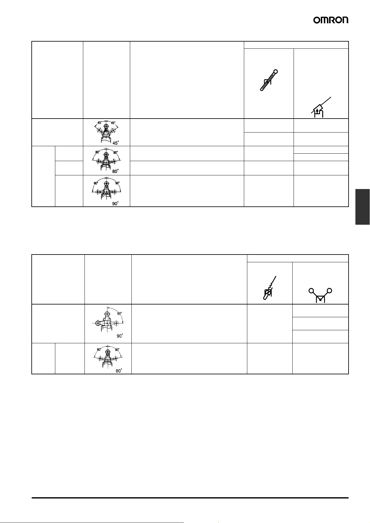
The overtravel models are classified into three types; general-purpose, high-sensitivity, and models which are capable of one-side 90° operation,
the -2N Series.
The -2N Series can also be installed on either side.
Since this model is identical to the standard model in dimensions, both models are interchangeable.
Like the standard model, it is oil-tight, waterproof, and dustproof (complies with IP67).
General-purpose, high sensitivity models Side-installation models
Head can be mounted in any of the four directions.
The lever operates on either side at 80°.
One-side operation is impossible.
The Head can be mounted in two directions, forward and backward.
The lever operates on either side at 90°.
One side operation is possible.
General-purpose/High Sensitivity Models
Note: 1. For all models WL@ indicates a standard model and WL01@ indicates a microload model.
2. One-side operation is not possible with the general-purpose and high-sensitivity models.
3. Unless otherwise indicated, a tolerance of ±0.4 mm applies to all dimensions.
Roller Lever Adjustable Rod Lever
WLH2
WL01H2
WLG2
WL01G2
17.5 dia. (length: 7) (see note 1)
38R
Four, M3.5
M5 (length: 12)
Allen-head bolt
Four,
+0.2
dia. holes
5.2
0
Three, M4
(length: 13)
JIS B0202 G1/2
Effective thread:
4 threads min.
60 max.
42 max.
Four, M6
Depth: 15 min.
WLHL
WL01HL
WLGL
WL01GL
Adjustable range:
25 to 140
3±0.2 dia.
(length: 160)
(see note 1)
Four, M3.5
M5 (length: 12)
Allen-head bolt
Four,
+0.2
5.2
0
Three, M4
(length: 13)
JIS B0202 G1/2
Effective thread:
4 threads min.
Allen-head
lock screw
dia. holes
55 max.
42 max.
Four, M6
Depth: 15 min.
Note: 1. Stainless sintered roller
2. WL@G2 is identical to other models except in
the shape of the set position marker plate.
3. The built-in switch for WLH2 is W-10FB3.
4. The built-in switch for WLG2 is W-10FB3-8.
Note: 1. WL@GL is identical to other models except in
the shape of the set position marker plate.
2. The built-in switch for WLHL is W-10FB3.
3. The built-in switch for WLGL is W-10FB3-8.
F-82 Two-circuit Limit Switch WL
Page 27

Adjustable Roller Lever
2
WLH12
WL01H12
WLG12
WL01G12
17.5 dia. (length: 7)
Adjustable range:
25 to 89
Four, M3.5
M5 (length:
12) Allenhead bolt
Four,
+0.2
5.2
0
dia. holes
Three, M4
(length: 13)
67 max.
42 max.
Four, M6
Depth: 15 min.
JIS B0202 G1/2
Effective thread:
4 threads min.
Note: 1. Stainless sintered roller
2. WL@G12 is identical to other models except in
the shape of the set position marker plate.
3. The built-in switch for WLH12 is W-10FB3.
4. The built-in switch for WLG12 is W-10FB3-8.
Operating characteristics WLH2
WL01H2
WLG2
WL01G2
WLHL
WL01HL
(See note 2.)
WLGL
WL01GL
(See note 2.)
WLH12
WL01H12
(See note 1.)
(See note 1.)
Operating force: OF max. 9.81 N 9.81 N 2.84 N 2.84 N 9.81 N 9.81 N
Release force: RF min. 0.98 N 0.98 N 0.25 N 0.25 N 0.98 N 0.98 N
+2
Pretravel: PT 15±5° 15±5° 15±5°
10°
−1
10°
+
−1
10°
Overtravel: OT min. 55° 65° 55° 65° 55° 65°
Movement differential: MD
12° 7° 12° 7° 12° 7°
max.
Note: 1. The operating characteristics of WLH12, WL01HL12, WLG12, and WL01G12 are measured at the lever length of 38 mm.
2. The operating characteristics of WLHL, WL01HL, WLGL, and WL01GL are measured at the rod length of 140 mm.
OF and RF for WLH12 and WL01H12, with a lever length of 89 mm.
Operating
characteristics
WLH12,
WL01H12
WLG12,
WL01G12
OF 4.18 N 4.18 N
RF 0.42 N 0.42 N
WLG12
WL01G12
+2
−
1
Limit
Switches
Two-circuit Limit Switch WL F-83
Page 28

Note: 1. For all models WL@ indicates a standard model and WL01@ indicates a microload model.
2. Unless otherwise indicated, a tolerance of ±0.4 mm applies to all dimensions.
Adjustable Rod Lever Rod Spring Lever
WLHAL4
WL01HAL4
Adjustable range:
350 to 380
Note: Stainless steel rod Note: Piano wire
Operating characteristics WLHAL4
Operating force: OF max. 0.98 N 0.90 N
Release force: RF min. 0.15 N 0.09 N
Pretravel: PT 15±5° 15±5°
Overtravel: OT min. 55° 55°
Movement differential: MD
max.
Note: 1. With WLHAL4, WL01HAL4, WLHAL5, and WL01HAL5, the
actuator’s tare is large, so depending on the installation direction, they may not be properly reset. Always install so
that the actuator is facing downwards.
3.2 dia. (see note)
M5 (length:
16) Allenhead bolt
Four,
+0.2
5.2
dia. holes
0
Three, M4
(length: 13)
JIS B0202 G1/2
Effective thread:
4 threads min.
WL01HAL4
(See note 2.)
12° 12°
42 max.
WL01HAL5
Four, M6
Depth: 15 min.
WLHAL5
WLHAL5
WL01HAL5
2. The operating characteristics of WLHAL4, and WL01HAL4
are measured at the rod length of 380 mm.
2.3 dia. (see note)
M5 (length: 16)
Allen-head bolt
Four,
+0.2
5.2
dia. holes
0
Three, M4
(length: 13)
JIS B0202 G1/2
Effective thread:
4 threads min.
42 max.
Four, M6
Depth: 15 min.
Side-installation Models
90° operation on one side is possible by simply changing the direction of the cam.
Note: 1. For all models WL@ indicates a standard model and WL01@ indicates a microload model.
2. With the side-installation models, 90° operation on one side is possible by simply changing the direction of the cam.
3. Unless otherwise indicated, a tolerance of ±0.4 mm applies to all dimensions.
60 max.
Roller Lever Adjustable Roller Lever
WLCA2-2N
WL01CA2-2N
17.5 dia. (length: 7) (see note)
Four, M3
38R
Two , M 5
(length: 18)
M5 (length:
12) Allenhead bolt
Four, 5.2
dia. holes
Two, 5.2
Three, M4
(length: 13)
JIS B0202 G1/2
Effective thread:
4 threads min.
+0.2
+0.2
0
dia.
0
Four, M6
Depth: 15 min.
WLCA12-2N
WL01CA12-2N
Note: Stainless sintered roller Note: Stainless sintered roller
42 max.
17.5 dia. (length: 7) (see note)
Adjustable range:
25 to 89
Four, M3
Two , M 5
(length: 18)
M5 (length:
16) Allenhead bolt
Two, 5.2
Three, M4
(length: 13)
JIS B0202 G1/2
Effective thread:
4 threads min.
+0.2
0
dia.
67 max.
42 max.
Four, M6
Depth: 15 min.
F-84 Two-circuit Limit Switch WL
Page 29

Adjustable Rod Lever
WLCL-2N
WL01CL-2N
Adjustable range:
25 to 140
3 ±0.2 dia. (length:
160) (see note)
M8 (length: 12)
Allen-head
lock screw
Four, M3
Two , M 5
(length: 18)
M5 (length:
12) Allenhead bolt
Four, 5.2
dia. holes
Two, 5.2
Three, M4
(length: 13)
+0.2
55 max.
+0.2
0
dia.
0
JIS B0202 G1/2
Effective thread:
4 threads min.
Note: Stainless steel rod
Operating characteristics WLCA2-2N
42 max.
Four, M6
Depth: 15 min.
WL01CA2-2N
WLCA12-2N
WL01CA12-2N
(See note 1.)
WLCL-2N
WL01CL-2N
(See note 2.)
Operating force: OF max. 9.61 N 9.61 N 2.84 N
Release force: RF min. 1.18 N 1.18 N 0.25 N
Pretravel: PT max. 20° 20° 20°
Overtravel: OT min. 70° 70° 70°
Movement differential: MD max. 10° 10° 10°
Note: 1. The operating characteristics of WLCA12-2N and WL01CA12-2N are measured at the lever length of 38 mm.
2. The operating characteristics of WLCL-2N and WL01CL-2N are measured at the rod length of 140 mm.
OF and RF for WLCA12-2N and WL01CA12-2N, with a lever length of 89 mm.
Operating
WLCA12-2N, WL01CA12-2N
characteristics
OF 4.10 N
RF 0.50 N
High-precision Models
The high-precision models feature a pretravel of 5° (as compared with 15° for the standard models) and a repeat accuracy twice as great as standard models. The high-precision models are ideal for positioning control of machine tools.
For all models WL@ indicates a standard model and WL01@ indicates a microload model.
Note: Unless otherwise indicated, a tolerance of ±0.4 mm applies to all dimensions.
Limit
Switches
Roller Lever
WLGCA2
WL01GCA2
Note: Stainless sintered roller
17.5 dia. (length: 7) (see note)
38R
Four, M3.5
M5 (length: 12)
Allen-head bolt
Four,
+0.2
5.2
dia. holes
0
Three, M4
(length: 13)
JIS B0202 G1/2
Effective thread:
4 threads min.
60 max.
42 max.
Four, M6
Depth: 15 min.
Operating characteristics WLGCA2
Operating force: OF max. 13.34 N
Release force: RF min. 1.47 N
Pretravel: PT
+2
5°
0
Overtravel: OT min. 40°
Movement differential: MD max. 3°
WL01GCA2
Two-circuit Limit Switch WL F-85
Page 30

Lamp-equipped Models
y
Roller Lever
WLCA2-LE/LD
WL01CA2-LE/LD
17.5 dia. (length: 7)
Stainless steel roller
38R
Four, M3.5
M5 (length: 12)
Allen-head bolt
Four,
+0.2
5.2
0
Three, M4
(length: 13)
dia. holes
60 max.
Note: Unless otherwise indicated, a tolerance of ±0.4 mm
applies to all dimensions.
OF max. 13.34 N
RF min. 2.23 N
PT 15±5°
OT min. 30°
MD max. 12°
Four, M6
Depth: 15 min
Note:
Stainless steel roller
JIS B0202 G1/2
Effective thread:
4 threads min.
42 max.
Sensor I/O Connector Models
Roller Lever Models
Standard Model (WLCA2), High-precision Model (WLGCA2), Overtravel Model (WLH2), and Overtravel High-sensitivity
Model (WLG2)
Note: 1. For the WLG2 model, only the dimensions for the set position marker plate change.
2. Unless otherwise indicated, a tolerance of ±0.4 mm applies to all dimensions.
3. The above diagram is for a lamp-equipped model.
Direct-wired Connector Models
60 max.
17.5 dia.
(length: 7)
(see note)
38R
Four,, M3.5
M5 (length: 12)
Allen-head bolt
Four,
+0.2
dia. holes
5.2
0
Three, M4
(length: 13)
Pre-wired Connector Models
60 max.
17.5 dia.
(length: 7)
(see note)
38R
Four, M3.5
M5 (length:
12) Allenhead bolt
Four,
+0.2
dia. holes
5.2
0
Three, M4
(length: 13)
Four, M6
JIS B0202 G1/2
Effective thread:
4 threads min.
Note: Stainless sintered roller
42 max.
Depth: 15 min.
F-86 Two-circuit Limit Switch WL
SC-1M
XS2H-D421
Note: Stainless sintered allo
42 max.
Four, M6
Depth: 15 min.
6 dia.
roller
Page 31

Operating characteristics Roller lever/Standard
model
Roller lever/High
precision model
Roller lever/Overtravel
model
Roller lever/Overtravel
high sensitivity model
Operating force: OF max. 13.34 N 13.34 N 9.81 N 9.81 N
Release force: RF min. 2.23 N 1.47 N 0.98 N 0.98 N
+2°
Pretravel: PT 15±5° 15±5°
5°
−
°
10°
Overtravel: OT min. 30° 40° 55° 65°
Movement differential: MD
12° 3° 12° 7°
max.
Top-roller Plunger
WLD2
Note: 1. Unless otherwise indicated, a tolerance of ±0.4 mm applies to all dimensions.
2. The above diagram is for a lamp-equipped model.
+2°
−
°
Direct-wired Connector Models
17 dia. (length: 5)
(see note)
OP
Note: Stainless sintered roller
Operating characteristics Top-roller plunger
Operating force: OF max. 26.67 N
Release force: RF min. 8.92 N
Pretravel: PT max. 1.7 mm
Overtravel: OT min. 5.6 mm
Movement differential: MD max. 1 mm
Operating position: OP 44±0.8 mm
Total travel position: TTP max. 39.5 mm
Four, M3.5 (length: 10)
Four,
+0.2
dia. holes
5.2
0
Three, M4 (length: 13)
JIS B0202 G1/2
Effective thread:
4 threads min.
42 max.
Four, M6
Depth: 15 min.
actuator
Pre-wired Connector Models
17 dia. (length: 5)
(see note)
OP
Four, M3.5 (length: 10)
Four,
+0.2
dia. holes
5.2
0
Three, M4 (length: 13)
SC-1M
XS2H-D421
Note: Stainless sintered roller
42 max.
42 max.
Four, M6
Depth: 15 min.
6 dia.
Limit
Switches
Two-circuit Limit Switch WL F-87
Page 32

Sealed Top-roller Plunger
WLD28
Note: 1. Unless otherwise indicated, a tolerance of ±0.4 mm applies to all dimensions.
2. The above diagram is for a lamp-equipped model.
Direct-wired Connector Models
11.2 dia. (length: 5)
(see note)
OP
Note: Stainless sintered alloy roller
Operating characteristics Sealed top-roller plunger
Operating force: OF max. 16.67 N
Release force: RF min. 4.41 N
Pretravel: PT max. 1.7 mm
Overtravel: OT min. 5.6 mm
Movement differential: MD max. 1 mm
Operating position: OP 44±0.8 mm
Total travel position: TTP max. 39.5 mm
Four, M3.5 (length: 10)
Four,
+0.2
dia. holes
5.2
0
Three, M4 (length: 13)
JIS B0202 G1/2
Effective thread:
4 threads min.
42 max.
Four, M6
Depth: 15 min.
actuator
Pre-wired Connector Models
11.2 dia. (length: 5)
(see note)
OP
Four, M3.5 (length: 10)
Four,
+0.2
dia. holes
5.2
0
Three, M4 (length: 13)
SC-1M
XS2H-D421
Note: Stainless sintered alloy roller
42 max.
Four, M6
Depth: 15 min.
F-88 Two-circuit Limit Switch WL
Page 33

■ Environment-resistant Models
The dimensions and operating characteristics are the same as general-purpose, environment-resistant models.
■ Spatter-prevention Models
Roller Lever (Screw Terminals)
WLCA2-@S/WL01@-@S
WLH2-@S/WLG2-@S
WLGCA2-@S
60 max.
17.5 dia. (length: 7) (see note)
Four, M3.5 head
clamping screws
38R
Note: Stainless steel roller
Roller Lever (Pre-wired Connector)
WLCA2-@S-M1J/WL01@-@S-M1J
WLH2-@S-M1J/WLG2-@S-M1J
WLGCA2-@S-M1J
Note: The dimensions are the same regardless of the number of core lines.
17.5 dia. (length: 7) (see note)
Four, M3.5 head
clamping screws
Two, M5 Allenhead nut and
arm set screw
+0.2
Four, 5.2
0
dia. holes
Teflon cap
Three, M4
(length: 13)
Lamp cover
14.7
58.7±
5
(25)
300
+100
−50
38R
0.2
Two, M5 Allen-head
nut and arm set screw
Four, 5.2
Three, M4 (length: 13)
60 max.
1.5
53±
1.5
41.5±
1.5
40±
13.1
25.4
12.7
Four, M6
Depth: 15 min.
6 dia.
+0.2
dia. holes
0
Teflon cap
Lamp cover
JIS B0202 G1/2
Effective thread:
4 threads min.
25.4
68.7
SC-1M
42 max.
Four, M6
Depth: 15 min.
Limit
Switches
(15.1)
30.2±
40±
0.2
0.7
XS2H-D421
(4.9)
Note: Stainless steel roller
53.2±
21.6
29.2±
35
42 max.
0.8
1.2
Operating characteristics Standard Overtravel models High-precision
General High-sensitivity
Operating force: OF max. 13.34 N 9.81 N 9.81 N 13.34 N
Release force: RF min. 2.23 N 0.98 N 0.98 N 1.47 N
Pretravel: PT 15°±5° 15°±5°
10°
+2
−1
+2°
5°
−0°
Overtravel: OT min. 30° 55° 65° 40°
Movement differential: MD max. 12° 12° 7° 3°
Two-circuit Limit Switch WL F-89
Page 34

Sealed Top-roller Plunger (Screw Terminals)
WLD28-@S
11.2 dia. (length: 5) (see note)
OP
Four, M3.5
Four, 5.2
+0.2
dia. holes
0
Lamp cover
Three, M4 (length: 13)
Note: Stainless steel roller
JIS B0202 G1/2
Effective thread:
4 threads min.
42 max.
Four, M6
Depth: 15 min.
Sealed Top-roller Plunger (Pre-wired Connector)
WLD28-@S-M1J
Note: The dimensions are the same regardless of the number of core lines.
l
11.2 dia. (length: 5) (see note)
OP
58.7±
5
(25)
300
PT
0.2
+100
−50
Rubber cap (fluorosilicon)
Four, M3.5 (length: 10)
push-in mounting screws
with spring washers
+0.2
Four, 5.2
dia. holes
0
Three, M4
(length: 13)
Lamp cover
XS2H-D421
(15.1)
(4.9)
0.2
30.2±
0.7
40±
Note: Stainless steel roller
Operating characteristics WLD28-L@S
Operating force: OF max. 16.67 N
Release force: RF min. 4.41 N
Pretravel: PT max. 1.7 mm
Overtravel: OT min. 5.6 mm
Movement differential: MD max. 1 mm
Operating position: OP 44±0.8 mm
Total travel position: TTP max. 39.5 mm
Note: Unless otherwise indicated, a tolerance of ±0.4 mm applies to all dimensions.
29.2±
35
42 max.
13.1
12.9
21.6
1.2
68.7
Four, M6
Depth: 15 min.
SC-1M
6 dia.
F-90 Two-circuit Limit Switch WL
Page 35

■ Actuators (Levers Only)
Note: 1. Lever: Only rotating lever models are illustrated.
2. Unless otherwise indicated, a tolerance of ±0.4 mm applies to all dimensions.
3. When using the adjustable roller (rod) lever, make sure that the lever is facing downwards. Use caution, as telegraphing (the Switch turns
ON and OFF repeatedly due to inertia) may occur.
WL-1A100
Standard Lever
17.5 dia. (length: 7) stainless
sintered alloy roller
7.3-dia.
mounting
holes
M5
Allen-head bolt
WL-1A118
Nylon Roller:
Roller Width: 30 mm
17.5 dia. (length: 30)
Nylon roller
38
7.3-dia.
mounting
holes
M5
Allen-head bolt
WL-1A115
Resin Roller
17.5 dia. (length: 7)
resin roller
7.3-dia.
mounting
holes
M5
Allen-head bolt
WL-1A105
Double Nut
17.5 dia. (length: 7) stainless
sintered alloy roller
7.3-dia.
mounting
holes
Two, M5 Allen-head
nut and arm set screw
WL-1A400
Bearing Roller
17 dia. (length: 6)
bearing roller
7.3-dia.
mounting
holes
M5
Allen-head bolt
WL-1A103S
Spatter Prevention
17.5 dia. (length: 7)
stainless steel roller
7.3-dia.
mounting
holes
M5
Allen-head bolt
Limit
Switches
WL-1A200
Lever Length: 50
Roller Width: 15
17.5 dia. (length: 15)
stainless sintered roller
7.3-dia.
mounting
holes
M5
Allen-head bolt
WL-1A300
Lever Length: 63
17.5 dia. (length: 7)
stainless sintered roller
7.3-dia.
mounting
holes
M5
Allen-head bolt
WL-2A100
17.5 dia. (length: 7) stainless
sintered alloy roller
Adjustable lever:
stainless steel
Adjustable range:
25 to 89
7.3-dia.
mounting
holes
M5
Allen-head
bolt
Two-circuit Limit Switch WL F-91
Page 36

WL-2A111
Resin Roller
17.5 dia. (length: 7)
resin roller
Adjustable lever:
stainless steel
Adjustable range:
25 to 89
WL-2A107
Double Nut
17.5 dia. (length: 7) stainless
sintered alloy roller
Adjustable lever:
stainless steel
Adjustable range:
28 to 88
WL-2A108
Resin Roller
17.5 dia. (length: 7)
resin roller
Adjustable lever:
stainless steel
Adjustable range:
25 to 140
M5
Allen-head
bolt
7.3-dia.
7.3-dia.
mounting
holes
M5
Allen-head
bolt
mounting
holes
WL-2A122 WL-2A106
17.5 dia. (length: 7) stainless
sintered alloy roller
Adjustable lever:
stainless steel
Adjustable range:
25 to 140
7.3-dia.
mounting
holes
M5
Allen-head
bolt
17.5 dia. (length: 7) stainless
sintered alloy roller
Adjustable lever:
stainless steel
Adjustable range:
25 to 89
7.3-dia.
mounting
holes
Two, M5 Allen-head
nut and arm set screw
M5
Allen-head
bolt
7.3-dia.
mounting
holes
WL-2A130
17.5 dia. (length: 7)
stainless steel roller
(21.8)
(10)
(10)
(112)
Note: Can be installed on the rear side.
WL-2A104 WL-2A110 WL-2A105
50 dia. (length: 6)
Nylon roller
50 dia. (length: 15)
Nylon roller
49 dia. rubber roller
Material: EPDM
89.5R
Three,
5.3
7.3
mounting holes
Two, M5 (length:
15.9
16) Allen-head
20
nut and arm set
screw
+0.2
dia. holes
0
+0.1
-dia.
0
24.7±
19.5
22.1
0.8
0.8
±
3
Adjustable from
42 to 89
7.3-dia.
mounting
holes
M5
Allen-head
bolt
Adjustable from
41 to 78.5
7.3-dia.
mounting
holes
M5
Allenhead bolt
Adjustable from
16 to 89
7.3-dia.
mounting
holes
M5
Allen-head
bolt
F-92 Two-circuit Limit Switch WL
Page 37

WL-1A106 WL-1A110 WL-4A100
50 dia. (length: 6)
Nylon roller
35 dia. (length: 6)
Nylon roller
Adjustable
up to
141
38R
3-dia. stainless
steel rod
7.3-dia. mounting
holes
M5 Allen-head
bolt
38R
M5
Allen-head
bolt
7.3-dia.
mounting
holes
WL-4A201 WL-3A100
M5
Allen-head
bolt
7.3-dia.
mounting
holes
WL-3A106
Double Nut
3.2-dia.
2-dia. stainless
Adjustable to
a maximum
of 290
steel for spring
13 dia.
7.3-dia. mounting
holes
M5
Allen-head
bolt
Actuator's
center of
rotation
7.3-dia. mounting
holes
Adjustable from
350 to
380
WL-3A108 WL-3A200 WL-3A203
3.2-dia. stainless
Adjustable
from
630 to
660
steel rod
417.5±2
stainless
steel rod
M5
Allenhead bolt
2.3-dia. piano
wire
12.5 dia. max.
25.5 max.
Adjustable
from
350 to
380
7.3-dia. mounting
holes
3.2-dia. stainless
steel rod
Two, M5 Allenhead nut and
arm set screw
8 dia.
Cap
Adhesive
12.5 dia.
2.3-dia.
max.
operation
rod
25.5 max.
Limit
Switches
7.3-dia.
mounting
holes
WL-4A112
Adjustable up
to 141
M5
Allen-head
bolt
4-dia. stainless
steel rod
7.3-dia. mounting
holes M5
Allen-head
bolt
25.5 max.
7.3-dia.
mounting
holes
WL-2A129
Marking
M5
Allen-head
bolt
8R
Three, 5.3
dia. holes
+0.1
7.3
0
dia. mounting
holes
Tw o,
M5 (length:
16) Allenhead bolts
+0.2
0
24.6 max.
7.3-dia.
mounting
holes
M5
Allen-head bolt
24.6 max.
Two-circuit Limit Switch WL F-93
Page 38

WL-5A101 WL-5A103 WL-5A105
Two, 17.5 dia. (length: 7)
stainless sintered alloy
rollers
Two, 17.5 dia. (length: 7)
stainless sintered alloy
rollers
Two, 17.5 dia. (length: 7)
stainless sintered alloy
rollers
+0.1
7.3
dia.
0
WL-5A100 has a resin roller WL-5A102 has a resin roller WL-5A104 has a resin roller
38R
M5 (length: 16)
Allen-head bolt
Installation
Item Appropriate model/actuator Details
Changing the installation position of
the actuator
By loosening the Allen-head bolt on the
actuator lever, the position of the actuator can be set anywhere within the 360°.
With Lamp-equipped Switches, the actuator lever comes in contact with the top
of the lamp cover, so use caution when
rotating and setting the lever. When the
lever only moves forwards and backwards, it will not contact the lamp cover.
Changing the orientation of the Head
By removing the screws in the four corners of the Head, the Head can be set in
any of the four directions. Be sure to
change the plunger for internal operations at the same time. (The operational
plunger does not need to be changed on
overtravel general-purpose and highsensitivity models.) The roller plunger
can be set in either two positions at 90°.
WLCA2-2N and WL01CA2-2N can only
be set in either the forward or backward
direction.
7.3
+0.1
dia.
0
38R
M5 (length: 16)
Allen-head bolt
Roller Levers: WLCA2, WL01CA2,
WLH2, WL01H2, WLG2, WL01G2
Adjustable Roller Levers: WLCA12,
WL01CA12, WLH12, WL01H12,
WLG12, WL01G12
Adjustable Rod Levers: WLCL,
WL01CL, WLHL, WL01HL, WLGL,
WL01GL
Roller Levers: WLCA@, WL01CA@,
WLGCA@
Adjustable Rod Levers: WLCL,
WL01CL
Horizontal Plungers: WLSD@,
WL01SD@
Roller Plungers: WLD2, WL01D2
Sealed Roller Plungers: WLD28,
WL01D28.
Note: Does not include -RP60
Series or -141 Series.
Head
7.3
+0.1
dia.
0
38R
M5 (length: 16)
Allen-head bolt
Loosen the M5 × 12 bolt, set the
actuator's position and then tighten
the bolt again.
Loosen the screws.
Head
Loosen
the
screws.
F-94 Two-circuit Limit Switch WL
Page 39

Item Appropriate model/actuator Details
e
Changing the operating direction
By removing the Head on models which
can operate on one-side only, and then
changing the direction of the operational
plunger, one of three operating directions can be selected. In the case of
overtravel models, by loosening the rubber holder using either a coin or a flatblade screwdriver, and changing the direction of the internal rubber section,
one of three operating directions can be
selected.
The tightening torque for the screws on
the Head is 0.78 to 0.88 N·m.
Roller Levers: WLCA2, WL01CA2,
WLGCA2, WLMGCA2@
Adjustable Roller Levers: WLCA12,
WL01CA12
Adjustable Rod Levers: WLCL,
WL01CL
Overtravel Models: WLCA@-2N,
WL01CA@-2N
Note: The diagram at the right is not
correct for the overtravel -2N
models.
The output of the
Switch will be changed,
regardless of which
direction the lever is
pushed.
Operating
Operating
Not operating
The output of the
Switch will only be
changed when the lever
is pushed in one
direction.
Operating
Operating
Not operating
Operational
plunger
Operation in
both directions
Clockwise operation
Counterclockwise
operation
For details on overtravel -2N models, refer to page 28.
Cam direction changing procedure for side-installation
models
Loosen the cam holder with
a coin or screwdriver. Take
out the cam from the Switch.
Change the direction of the cam
as required by your intended operation and then reinstall the cam.
Relationship of cam to operation as observed from the rear of
Switch
Operation on both sides Operation on one side
Operates
Operates Operates
Does not operat
Limit
Switches
Installing the roller on the inside
By installing the roller lever in the opposite direction, the roller can be installed
on the inside. (Set so that operation can
be completed within a 180° level range.)
Roller Levers: WLCA@, WL01CA@,
except for the adjustable roller levers.
Fork Lever Locks: WLCA32-4@,
WL01CA32-4@
Operation on one side
Does not operate
Loosen the
Allen-head bolt.
Two-circuit Limit Switch WL F-95
Avoid this combination
Operates
Page 40

Item Appropriate model/actuator Details
Selecting the roller position
There are four types of fork lever lock for
use depending on the roller position.
Fork Lever Locks: WLCA32-4@,
WL01CA32-4@
WLCA32-41
WLCA32-43
Adjusting the length of the rod or lever
The length of the rod or lever can be adjusted by loosening the Allen-head bolt.
Adjustable Roller Levers: WLCA12,
WL01CA12 etc.
Adjustable Rod Levers: WLCL,
WL01CL, etc.
■ Operation of Fork Lever Locks
The fork lever lock is configured so that the dog pushes the lever to
reverse the output and this reversed state is maintained even after
the dog continues on. If the dog then pushes the lever from the opposite direction, the lever will return to its original position.
WLCA32-42
WLCA32-44
Note: An explanation of the operation of fork lever locks is pro-
vided after this table.
WLCA12 etc.
Loosen this
Allen-head
bolt and
adjust the
length of
the lever.
Adjustment range:
25 to 89 mm
Loosen this
Allen-head
bolt and
adjust the
length of
the rod.
Example
NC terminal: ON NO terminal: ON NO terminal: ON
F-96 Two-circuit Limit Switch WL
Page 41

Precautions
Refer to the Technical Information for Limit Switches (Cat. No. C121).
■ Correct Use
When a rod or wired-type actuator is used, do not touch the top end
of the actuator. Doing so may result in injury.
Applicable models: WLHAL5 and WL01HAL5 Rod Spring Levers and
WLNJ-S2 and WL01NJ-S2 Steel-wire Actuators.
A short-circuit may cause damage to the Switch, so insert a circuit
breaker fuse, of 1.5 to 2 times the rated current, in parallel with the
Switch. In order to meet EN approval ratings, use a 10-A fuse that
corresponds to IEC269, either a gI or gG for general-purpose types
and spatter-prevention models only.
When wiring terminal screws, use M4 round crimp terminals and
tighten screws to the recommended torque. Wiring with broken
wires, or the incorrect crimp terminals, or not tightening screws to the
recommended torque can lead to short-circuits, leakage current, and
fire.
When performing internal wiring there is a chance of short-circuit,
leakage current, or fire, so be sure to protect the inside of the Switch
from splashes of oil or water, corrosive gases, and cutting powder.
Using an inappropriate connector or assembling Switches incorrectly
(assembly, tightening torque) can result in malfunction, leakage current, or fire, so be sure to read the instruction manual thoroughly
beforehand.
Even when the connector is assembled and set correctly, the end of
the cable and the inside of the Switch may come in contact. This can
lead to malfunction, leakage current, or fire, so be sure to protect the
end of the cable from splashes of oil or water and corrosive gases.
Environmental Precautions
When the Switch is used in locations subject to splashes of water or
oil, the material of the seal, which ensures the sealing properties of
the Switch, may undergo changes in shape and quality. This is due to
deterioration (including expansion and contraction), and may result in
reduced performance, ineffective return, and ineffective sealing
(leading to ineffective contact, insulation, leakage current, and fire).
Confirm the possible effects of the operating environment on the
Switch before use.
Built-in Switch
Do not remove or replace the built-in switch. If the position of the
built-in switch moves, it can cause reduced performance, and if the
insulation sheet moves (separator), the insulation may become ineffective.
Tightening Torque
If screws are too loose they can lead to an early malfunction of the
Switch, so ensure that all screws are tightened using the correct
torque.
No. Type Torque
A Head mounting screw 0.78 to 0.88 N·m
B Cover mounting screw 1.18 to 1.37 N·m
C Allen-head bolt
(for securing the lever)
D Terminal screw 0.59 to 0.78 N·m
E Connector 1.77 to 2.16 N·m
F Main Unit screws 4.90 to 5.88 N·m
In particular, when changing the direction of the Head, make sure
that all screws are tightened again to the correct torque. Do not allow
foreign objects to fall into the Switch.
4.90 to 5.88 N·m
Installing the Switch
To install the Switch, make a mounting panel, as shown in the following diagram, and tighten screws using the correct torque.
Standard/Overtravel model Overtravel model (side
Mounting holes
Four, 5.2
+0.2
dia. holes
0
Mounting holes
installation)
+0.2
Two, 5.2
dia. holes
0
Limit
Switches
Connectors
Either the easy-to-use Allen-head nut or the SC Connector can be
used as connectors. To ensure high-sealing properties, use the SC
Connector. Consult your OMRON representative for details on SC
Connectors.
Two-circuit Limit Switch WL F-97
Page 42

Wiring
Use 1.25-mm lead wires and M4-insulation covered crimp terminals
for wiring.
Crimp Terminal External Dimensions
D dia.
dz dia.
dz dia.: 4.3
D dia.: 4.5
B: 8.5
L: 21.0
F: 7.8
l: 9.0 (mm)
Wiring Method
Switch Box Section
Rotating Lever Set Position
All rotating lever models, except the fork lever lock, have a set position marker plate. (See page 75.) After operation, set the indicator
needle on the marker plate so that is in the convex section of the
bearing.
Terminal Plate
By using a short circuit plate, as shown in the following diagram, the
Switch can be fabricated into a single-polarity double-break model.
When ordering specify WL Terminal Plate (product code: WL9662F).
Ground terminal
NO terminal
NC terminal
Note: The ground terminal is only installed on models with ground ter-
minals.
t = 0.6 Copper plate
ALL DIMENSIONS SHOWN ARE IN MILLIMETERS.
To convert millimeters into inches, multiply by 0.03937. To convert grams into ounces, multiply by 0.03527.
Cat. No. C001-E1-13
In the interest of product improvement, specifications are subject to change without notice.
F-98 Two-circuit Limit Switch WL
 Loading...