

Page 1
»
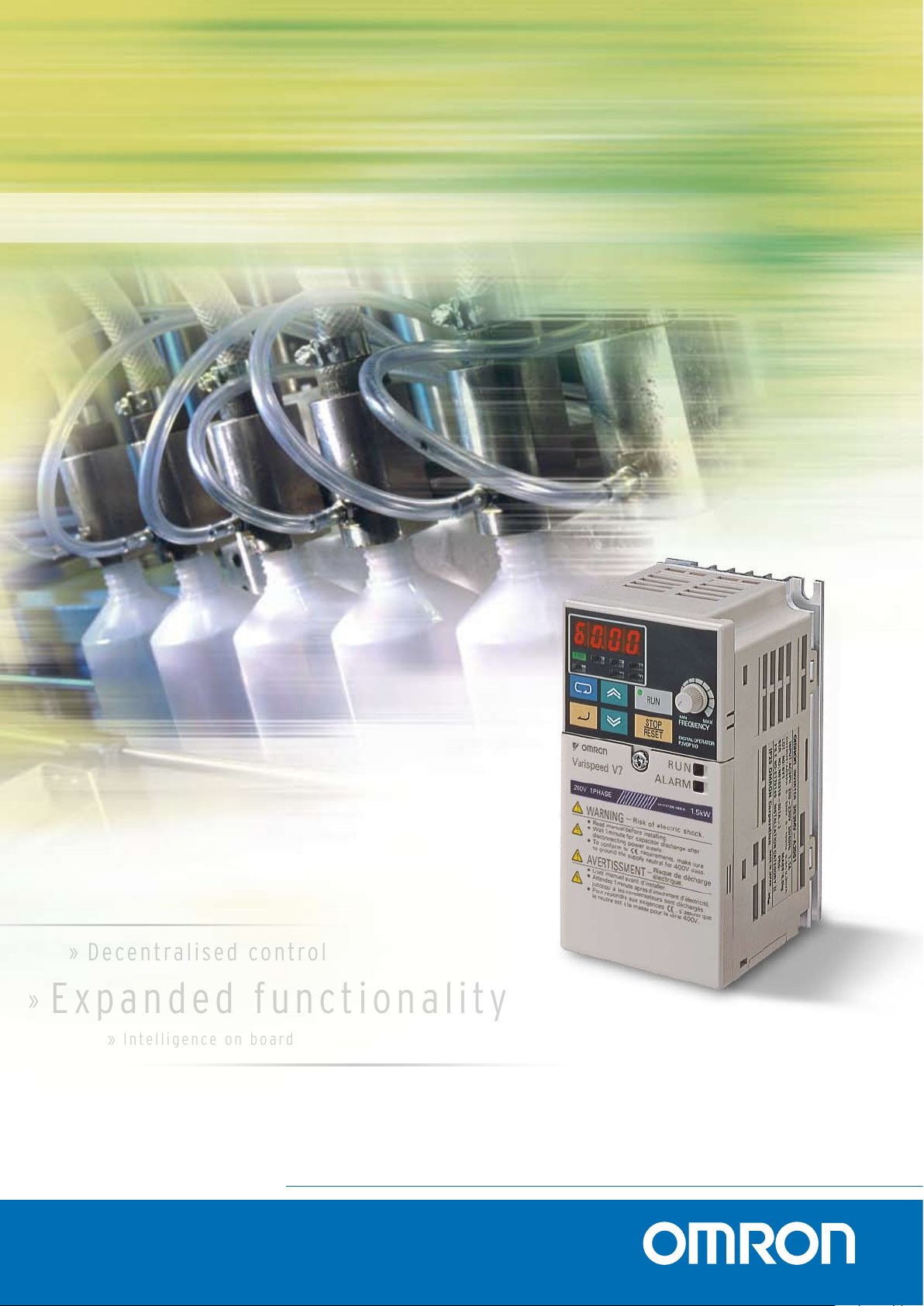
Decentra l i sed c o n t rol
» In te lli gen ce on bo ard
»
Ex pan d ed fun c tion a lit y
NEW V7 INVERTERS
I m p ro v i n g o n p e rf e c t i o n
Advanced Industrial Automation
Page 2
Europe’s first choice - V7 inverters
Robu s t IGBTs
T h e s e c re t i n s i d e
always meet your expectations
Since the V7 inverter was launched into the market,
Omron-Yaskawa has installed more than 1.5 million
of V7 series inverters world-wide. It has become
a market reference in reliability. The latter is not
some quantifiable parameter that one can just
mention in the specification sheet. It’s a rather
rigorous process built into the genes
of the product.
5%
3%
1%
1 year 5 years
Failure rate for drives
Market standard
Omron-Yaskawa
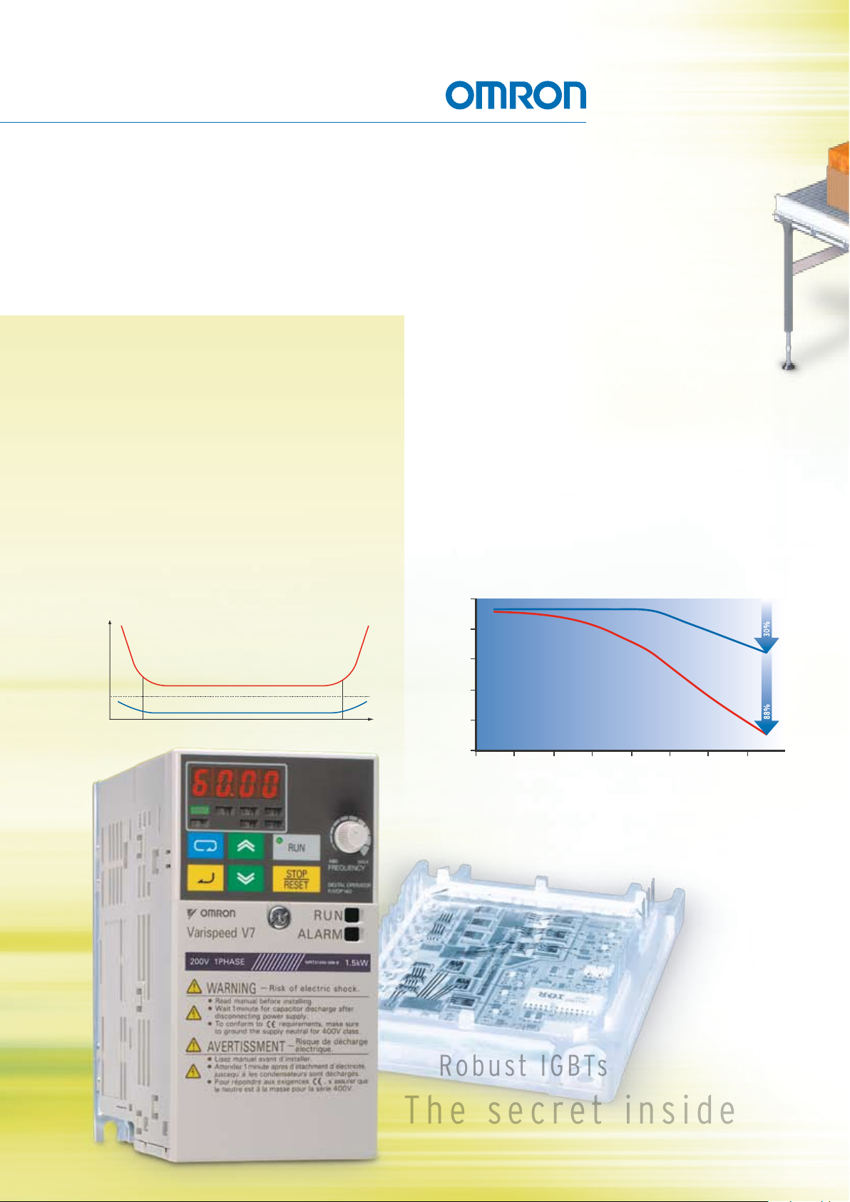
The secret of the leader is that it simply runs and runs
until you tell it to stop…
The V7 is designed to operate in the most severe environments.
Hence, it goes far beyond normal expectations (standard
published specifications). For example, it delivers 40% more
current than any inverter on the market. And it does this under
severe conditions, such as high carrier frequency, high
temperature, large voltage fluctuations, etc. The result is that
you get what’s in the box and much more.
Now that’s quality beyond a doubt!
Conventional inverter vs V7 Amps Derating
400V - 4,0 Kw at 40ºC
Omron Yaskawa V7AZ
Conventional inverter
C.Frq. (KHz)
Output (A)
10,00
8,00
6,00
4,00
2,00
Noisy operation Silent operation
0,00
2,5 3 5 6 7,5 10 12 14
Page 3
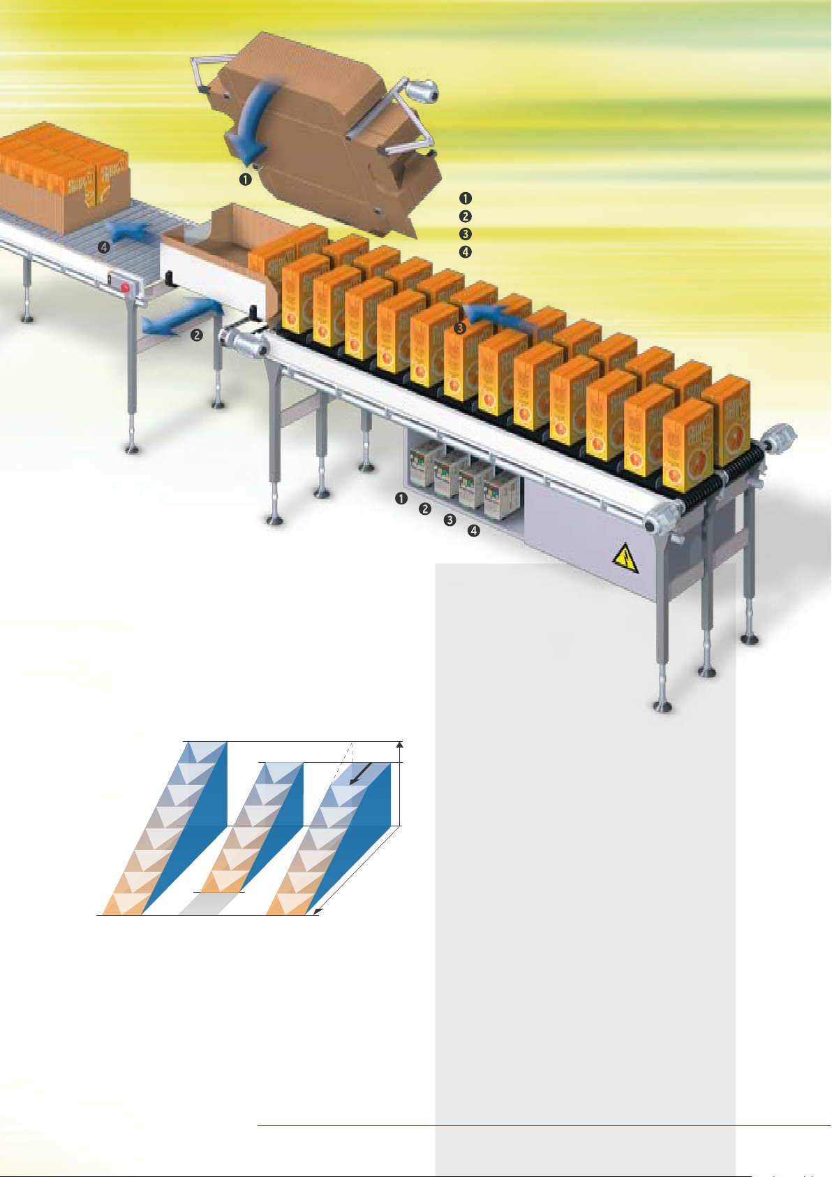
Rotating and static autotune
Product feed
Product out
Besides the standard rotating autotune function, the new
V7 series also features static autotune. This greatly eases drive
setup by eliminating the need to rotate the motor during
autotuning. The result - faster, easier and cheaper installation
and commissioning.
Position control at stop
Nominal speed
S
S>S
Speed
Packaging feed
Positioning
New features
• Sensor-less vector controller
ensures 100% at 0.5Hz
• Compact size available
in IP20 or IP65
• Silent operation
• Programming software:
CX-Drive for parameter configuration
• CASE (Inverter application software)
• PLC option board
• High speed Motion Bus: MECHATROLINK-II (ML-II)
• Connectivity: Memobus, Dnet, Profibus, CANopen
S: Travel distance
(blue area)
Preferred stop position
Standard stop at
nominal speed.
Unexpected stop position
Stopping without
position control.
Stopping with
position control.
Embodying advanced on-board processing, V7 inverters offer
unrivalled dynamic control, including fast braking and high-
precision positioning at stop. From full speed to full stop is
achieved faster than market standard inverters. Moreover, this
braking performance is completely independent of the motor
running speed, providing you with perfect control of
your machines.
Advanced Industrial Automation
Time
• New features:
- Autotuning
- Position control when stopping
- Carrier frequency up to 14KHz
- Analogue positioning
- Improved Up & Down function
- PTC input
- 2 Motors change function
- Free I/O’s setting to be used
from host controller
- Frequency Offsets
- New start / stop sequence
Page 4
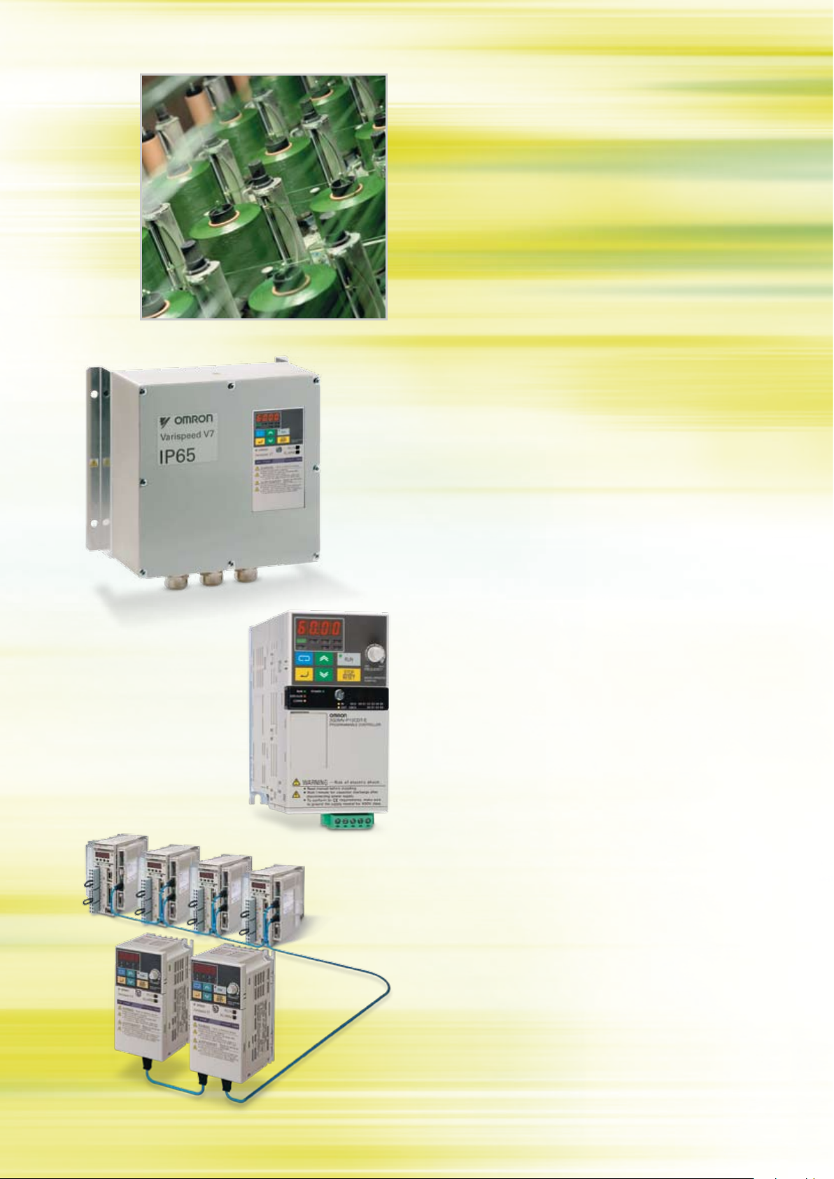
Cost-effective customisation with CASE
Special CASE (Customised Application Software) is available
for the V7 series to provide customised control without need
of any extra option boards. CASE gives standard inverters the
performance of a custom-made solution, allowing big savings
in hardware equipment and increasing system reliability.
Safe decentralised control
The V7 inverter is also available in a ruggedized IP65 housing,
enabling you to decentralise your drive control without any
extra cabinet costs. Operating independently of the main
control panel, this solution also reduces cabling and saves
on installation time.
PLC functionality
A PLC option board based on Omron’s market-leading PLC
technology offers you all the cost-saving benefits of PLC
functionality. It not only equips the V7 with extra functionality
for a broad range of digital control tasks, it also leads to
significant savings by eliminating the need for a separate PLC.
The board’s inverter-based architecture provides for wireless
installation and seamless access to all V7 parameters. And it
provides external communication via analogue/digital IOs.
MECHATROLINK-II
Using the Omron-Yaskawa MECHATROLINK-II digital motion bus,
you can use the same high-speed motion bus throughout your
machine, from motion controller, servo drives and now also the
inverter. This creates a fully integrated system for the most
advanced motion-control solutions.
Page 5
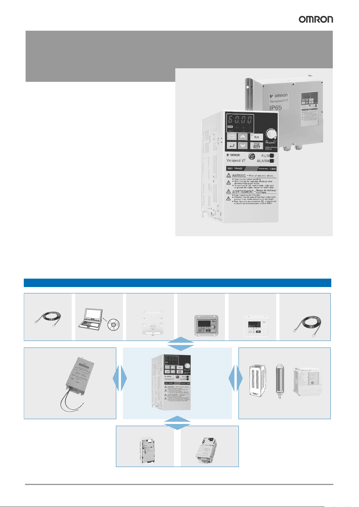
1Varispeed V7
CIMR-V7AZ
Varispeed V7
Sensorless vector in pocket size
• Nominal torque at 0.5 Hz
• Autotuning
• High carrier up to 14 khz
• Stop accuracy function.
• Integrated PID controller and bidirectional PID-out put
• Motor protection with PTC input
• Pulse input
• Standard digital operator with copy function
• Fieldbus: Modbus, DeviceNet, PROFIBUS, CANopen
• High speed motion bus: ML- II
• Plug-in PLC option unit. Total inverter access.
• CE, UL, and cUL marked
V7 IP65
• Compact size
• Easy wiring
• Built-in filter (Class B)
Customized software*
• The inverter software can be customized to meet
specific application. Examples:
• Traverse sofware S-9381.
*For detailed information please refer to case software section.
Ratings
• 200 V Class single-phase 0.1 to 4 kW
• 200 V Class three-phase 0.1 to 7.5 kW
• 400 V Class three-phase 0.2 to 7.5 kW
System configuration
*See note
*See note
* Option frames are needed for V7 IP65 type.
Communication unit
3G3IV-PCN329-E
Inverter to PC cable
3G3IV-PCN126/326
Digital operator
extension cable
CX-Drive
Braking accessories
PLC option unit
Varispeed
V7
Line filter
3G3IV-PEZZ8122_
DIN attachment
JVOP-144
Remote digital oper.
with potentiometer
JVOP-146
Remote digital oper.
with potentiometer
LKEB_
ERF150WJ_
CDBR_B
* V7 IP65 types are built-in filter inverters.
*See note
Varispeed V7 5
Page 6
2
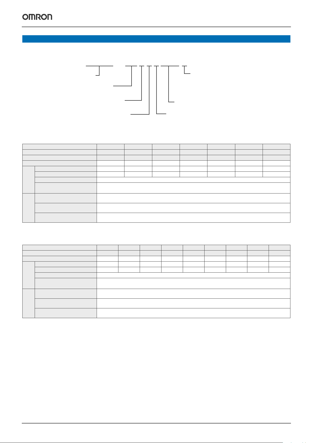
Frequency inverters
Type designation
200 V class
400 V class
Specifications
IP20 single-phase: CIMR-V7AZ B0P1 B0P2 B0P4 B0P7 B1P5 B2P2 B4P0
IP65 single-phase: CIMR-V7TZ --- --- B0P405 B0P705 B1P505 B2P205 ---
IP20 three-phase: CIMR-V7AZ 20P1 20P2 20P4 20P7 21P5 22P2 24P0
Maximum permissible motor output kW
1
1. Based on a standard 4-pole motor for maximum applicable motor output. Select the inverter model within the allowable motor rated current
0.12 0.25 0.55 1.1 1.5 2.2 4.0
Output
characteristics
Inverter capacity kVA
0.3 0.6 1.1 1.9 3.0 4.2 6.7
Rated output current A
0.8 1.6 3.0 5.0 8.0 11.0 17.5
Max. output voltage
Proportional to input voltage: 0..240 V
Max. output frequency
400 Hz
Power
supply
Rated input voltage
and frequency
Single-phase 200..240 V 50/60 Hz
3-phase 200..230 V 50/60 Hz
Allowable voltage
fluctuation
-15%..+10%
Allowable frequency
fluctuation
+5%
IP20 three-phase: CIMR-V7AZ
40P2 40P4 40P7 41P5 42P2 43P0 44P0 45P5 47P5
IP65 three-phase: CIMR-V7TZ
40P405 40P705 41P505 42P205 43P005 44P005
Maximum permissible motor output kW
1
1. Based on a standard 4-pole motor for maximum applicable motor output. Select the inverter model within the allowable motor rated current
0.37 0.55 1.1 1.5 2.2 3.0 4.0 5.5 7.5
Output
characteristics
Inverter capacity kVA
0.9 1.4 2.6 3.7 4.2 5.5 7.0 11.0 14.0
Rated output current A
1.2 1.8 3.4 4.8 5.5 7.2 9.2 14.8 18.0
Max. output voltage
Proportional to input voltage: 0..400 V
Max. output frequency
400 Hz
Power
supply
Rated input voltage
and frequency
3-phase 380..460 VAC, 50/60 Hz
Allowable voltage
fluctuation
-15%..+10%
Allowable frequency
fluctuation
+5%
Voltage
B: Single-phase 200 VAC
2: Three-phase 200 VAC
4: Three-phase 400 VAC
Z: European standard specifications
Inverter
V7 series
A: With digital operator (with potentiometer)
T: V7 IP65 type with digital operator
( without potentiometer )
C I M R — V 7 A Z B 0 P 1 0
Max. applicable motor output
0P1: 0.1 kW
7P5: 7.5 kW
~
"P" indicates a decimal
point
[ ]
Protective enclosure:
0: IP20
1: NEMA1
05: IP65
Varispeed V7
3
Commom specifications
Model number
CIMR-V7AZ-@
CIMR-V7TZ-@
Specifications
Control functions
Control methods
Sine wave PWM (V/f control, sensorless vector control)
Output frequency range
0.1..400 Hz
Frequency tolerance
Digital set value: ±0.01% (-10..+50 ºC)
Analogue set value: ±0.5% (25 ±10 ºC)
Resolution of frequency set value
Digital set value: 0.01 Hz (<100 Hz), 0.1 Hz (>100 Hz)
Analogue set value: 1/1000 of maximum frequency
Resolution of output frequency
0.01 Hz
Overload capability
150%/60 s
Frequency set value
0..10 V (20 kΩ), 4..20 mA (250 Ω), 0..20 mA (250 Ω)
Pulse train input, frequency setting value (selectable)
Braking torque
(short term peak torque)
Up to 200 W 150% or more
550 W to 1.1 kW 100% or more
1.5 kW 50% or more
>1.5 kW 20% or more
Continuous braking torque approx. 20% without, 150% with external braking resistor
Functionality
Binary inputs
7 freely programmable inputs
Binary outputs
1 relay output, 2 freely programmable open collector outputs
Analogue output
1 programmable analogue output (0..10 V)/pulse output
Analogue inputs
2 analogue inputs, 0..10 V, 4..20 mA, 0..20 mA
Braking/acceleration times
0.01..6000 s
Display
Optionally frequency, current or set value
Error and status LED
Protection functions
Motor overload protection Electronic thermal overload relay
Instantaneous overcurrent Motor coasts to a stop at approx. 250% of inverter rated current
Overload Motor coasts to a stop after 1 minute at 150% of inverter rated output current
Overvoltage Motor coasts to a stop if DC bus voltage exceed 410 V (double for 400 V class)
Undervoltage
Stops when DC bus voltage is approx. 200 V or less (double for 400 V class)
(approx. 160 V or less for single-phase series)
Momentary power loss
Following items are selectable: not provided (stop if power loss is 15 ms or longer), continuous operation
if power loss is approx. 0.5 s or shorter, continuous operation
Cooling fin overheat Protected by electronic circuit
Stall prevention level Individual levels during accel/constant speed. Decel ON/OFF available. During decel enable/disable selectable.
Cooling fan fault Detected by electronic circuit (fan lock detection)
Ground fault Protected by electronic circuit (operation level is approx. 250% of rated output current)
Power charge indication
RUN lamp stays ON or digital operator LED stays ON until the DC bus voltage becomes 50 V or less.
(Charge LED is provided for 400 V)
Ambient conditions
Degree of protection
IP20, NEMA1, IP65
Cooling
Self cooling for 200 V 0.1..0.4 kW (3 or single phase) and for 400 V 0.2..0.75 kW
Cooling fan for 200 V 0.75 to 7.5 kW and for 400 V 1.5 to 7.5 kW
Ambient temperature
Open air mounting: -10 ºC..50 ºC
Wall mounting: -10 ºC..40 ºC
Ambient humidity
95% (without condensation)
Storage temperature
-20 ºC..+60 ºC (short-term temperature during transportation)
Installation
Indoor (no corrosive gas, dust, etc.)
Installation height
Max. 1000 m
Vibration
10 to 20 Hz, 9.8 m/s2 max; 20 to 50 Hz, 2 m/s2 max
Varispeed V76
Page 7

Varispeed V7
3
Commom specifications
Model number
CIMR-V7AZ-@
CIMR-V7TZ-@
Specifications
Control functions
Control methods
Sine wave PWM (V/f control, sensorless vector control)
Output frequency range
0.1..400 Hz
Frequency tolerance
Digital set value: ±0.01% (-10..+50 ºC)
Analogue set value: ±0.5% (25 ±10 ºC)
Resolution of frequency set value
Digital set value: 0.01 Hz (<100 Hz), 0.1 Hz (>100 Hz)
Analogue set value: 1/1000 of maximum frequency
Resolution of output frequency
0.01 Hz
Overload capability
150%/60 s
Frequency set value
0..10 V (20 kΩ), 4..20 mA (250 Ω), 0..20 mA (250 Ω)
Pulse train input, frequency setting value (selectable)
Braking torque
(short term peak torque)
Up to 200 W 150% or more
550 W to 1.1 kW 100% or more
1.5 kW 50% or more
>1.5 kW 20% or more
Continuous braking torque approx. 20% without, 150% with external braking resistor
Functionality
Binary inputs
7 freely programmable inputs
Binary outputs
1 relay output, 2 freely programmable open collector outputs
Analogue output
1 programmable analogue output (0..10 V)/pulse output
Analogue inputs
2 analogue inputs, 0..10 V, 4..20 mA, 0..20 mA
Braking/acceleration times
0.01..6000 s
Display
Optionally frequency, current or set value
Error and status LED
Protection functions
Motor overload protection Electronic thermal overload relay
Instantaneous overcurrent Motor coasts to a stop at approx. 250% of inverter rated current
Overload Motor coasts to a stop after 1 minute at 150% of inverter rated output current
Overvoltage Motor coasts to a stop if DC bus voltage exceed 410 V (double for 400 V class)
Undervoltage
Stops when DC bus voltage is approx. 200 V or less (double for 400 V class)
(approx. 160 V or less for single-phase series)
Momentary power loss
Following items are selectable: not provided (stop if power loss is 15 ms or longer), continuous operation
if power loss is approx. 0.5 s or shorter, continuous operation
Cooling fin overheat Protected by electronic circuit
Stall prevention level Individual levels during accel/constant speed. Decel ON/OFF available. During decel enable/disable selectable.
Cooling fan fault Detected by electronic circuit (fan lock detection)
Ground fault Protected by electronic circuit (operation level is approx. 250% of rated output current)
Power charge indication
RUN lamp stays ON or digital operator LED stays ON until the DC bus voltage becomes 50 V or less.
(Charge LED is provided for 400 V)
Ambient conditions
Degree of protection
IP20, NEMA1, IP65
Cooling
Self cooling for 200 V 0.1..0.4 kW (3 or single phase) and for 400 V 0.2..0.75 kW
Cooling fan for 200 V 0.75 to 7.5 kW and for 400 V 1.5 to 7.5 kW
Ambient temperature
Open air mounting: -10 ºC..50 ºC
Wall mounting: -10 ºC..40 ºC
Ambient humidity
95% (without condensation)
Storage temperature
-20 ºC..+60 ºC (short-term temperature during transportation)
Installation
Indoor (no corrosive gas, dust, etc.)
Installation height
Max. 1000 m
Vibration
10 to 20 Hz, 9.8 m/s2 max; 20 to 50 Hz, 2 m/s2 max
Frequency inverters 7
Page 8

4
Frequency inverters
Digital operator
Indicators
(setting/monitor
item indicators)
Data display
FREQUENCY
adjuster
Operation keys
Appearance Name Function
Data display Displays relevant data items, such as frequency reference, output frequency,
and parameter set values.
Frequency adjuster Sets the frequency reference within a range between 0 Hz and the maximum frequency.
1
Frequency reference indicator The frequency reference can be monitored or set while this indicator is lit.
Output frequency indicator The output frequency of the inverter can be monitored while this indicator is lit.
Output current indicator The output current of the inverter can be monitored while this indicator is lit.
Multi-function monitor indicator The values set in U01 through U10 are monitored while this indicator is lit.
Forward/reverse selection indicator The direction of rotation can be selected while this indicator is lit when operating the inverter
with the RUN key.
Local/remote selection indicator The operation of the inverter through the digital operator or according to the set parameters is
selectable while this indicator is lit.
2
Parameter setting indicator The parameters in n001 through n179 can be set or monitored while this indicator is lit.
3
Mode key Switches the simplified-LED (setting and monitor) item indicators in sequence.
Parameter being set will be canceled if this key is pressed before entering the setting.
Increment key Increases multi-function monitor numbers, parameter numbers, and parameter set values.
Decrement key Decreases multi-function monitor numbers, parameter numbers, and parameter set values.
Enter key Enters multi-function monitor numbers, parameter numbers, and internal data values after they
are set or changed.
RUN key Starts the inverter running when the 3G3MV is in operation with the digital operator
STOP/RESET key Stops the inverter unless parameter n007 is set to disable the STOP key.
Used to reset the inverter when an error occurs.
4
1. V7 IP65 types have digital operator without frequency adjuster.
2. The status of the local/remote selection indicator can be only monitored while the inverter is in operation. Any RUN comand input is ignored while this
indicator is lit.
3. While inverter is in operation, the parameters can be only monitored and only some parameters can be changed. Any RUN command is ignored while the
parameter setting indicator is lit.
4. For safety reasons, the reset function cannot be used while an operation instruction (forward/reverse) is being input. Turn the operation instruction OFF
before using this function.
Varispeed V7
5
Frequenc
IP 20 type 0.1 to 4 Kw
IP20 / NEMA1 type 5.5/7.5 Kw
Dimensions
Voltage class
Max. applicable
motor output kW
Inverter model
CIMR V7AZ
Figure
Dimensions in mm
Weight kg
Cooling
method
W H D W1 H1 H2 D1
Three-phase
200 V
0.12 20P1
1 68
128
76
56
118
5
10
0.6
Self cooled0.25 20P2 0.6
0.55 20P4 108 42 0.9
1.1 20P7 128 62 1.1
Fan cooled
1.5 21P5
2
108
131
96
5
64
1.4
2.2 22P2 140 1.5
4.0 24P0 140 143 128 71 2.1
Single-phase
200 V
0.12 B0P1
1 68
128
76
56 118 5
10
0.6
Self cooled0.25 B0P2 76 0.7
0.55 B0P4 131 42 1.0
1.1 B0P7
2
108
140 96
118 5
64
1.5
Fan cooled
1.5 B1P5 156 96 1.5
2.2 B2P2 140 163 128
71
2.2
4.0 B4P0 170 180 158 2.9
Three-phase
400 V
0.37 40P2
2
108
128
92
96
118 5
16 1.0
Self cooled0.55 40P4 110 34 1.1
1.1 40P7 140
64
1.5
1.5 41P5
156
1.5
Fan cooled
2.2 42P2 1.5
3.0 43P0
140 143 128 71
2.1
4.0 44P0 2.1
Voltage class
Max. applicable
motor output kW
Inverter model
CIMR - V7AZ
Figure
Dimensions in mm (inches)
Weight kg
Cooling
method
W H D W1 H1 H2 D1
Three-phase
200 V
5.5 25P5
3
180 260 170 164 244 8 65
4.6
Fan cooled
7.5 27P5 4.8
Three-phase
400 V
5.5 45P5
180 260 170 164 244 8 65
4.8
7.5 47P5 4.8
W 1
D
D1
8.5
(0.34)
W
H 2 H 1
H
2 M4
W 1
W
H 2 H 1
H
4 M4
D
8.5
(0.34)
D1
Figure 1 Figure 2
Figure 3
Varispeed V78
Page 9

Varispeed V7
5
Frequenc
IP 20 type 0.1 to 4 Kw
IP20 / NEMA1 type 5.5/7.5 Kw
Dimensions
Voltage class
Max. applicable
motor output kW
Inverter model
CIMR V7AZ
Figure
Dimensions in mm
Weight kg
Cooling
method
W H D W1 H1 H2 D1
Three-phase
200 V
0.12 20P1
1 68
128
76
56
118
5
10
0.6
Self cooled0.25 20P2 0.6
0.55 20P4 108 42 0.9
1.1 20P7 128 62 1.1
Fan cooled
1.5 21P5
2
108
131
96
5
64
1.4
2.2 22P2 140 1.5
4.0 24P0 140 143 128 71 2.1
Single-phase
200 V
0.12 B0P1
1 68
128
76
56 118 5
10
0.6
Self cooled0.25 B0P2 76 0.7
0.55 B0P4 131 42 1.0
1.1 B0P7
2
108
140 96
118 5
64
1.5
Fan cooled
1.5 B1P5 156 96 1.5
2.2 B2P2 140 163 128
71
2.2
4.0 B4P0 170 180 158 2.9
Three-phase
400 V
0.37 40P2
2
108
128
92
96
118 5
16 1.0
Self cooled0.55 40P4 110 34 1.1
1.1 40P7 140
64
1.5
1.5 41P5
156
1.5
Fan cooled
2.2 42P2 1.5
3.0 43P0
140 143 128 71
2.1
4.0 44P0 2.1
Voltage class
Max. applicable
motor output kW
Inverter model
CIMR - V7AZ
Figure
Dimensions in mm (inches)
Weight kg
Cooling
method
W H D W1 H1 H2 D1
Three-phase
200 V
5.5 25P5
3
180 260 170 164 244 8 65
4.6
Fan cooled
7.5 27P5 4.8
Three-phase
400 V
5.5 45P5
180 260 170 164 244 8 65
4.8
7.5 47P5 4.8
W 1
D
D1
8.5
(0.34)
W
H 2 H 1
H
2 M4
W 1
W
H 2 H 1
H
4 M4
D
8.5
(0.34)
D1
Figure 1 Figure 2
Figure 3
Frequency inverters 9
Page 10

6
Frequency inverters
IIP65 type 0.55 to 4 Kw
Voltage
class
Max.
applicable
motor
output kW
Inverter
model
CIMR V7TZ
Figure
Dimensions in mm
Weight kgCooling
method
W H D W1 W2 H1 H2 H3 D1
Single-phase
200 V
0.55 B0P405
4
280 240 142 260 228 165 38 275 44
3.4 Self cooled
1.1 B0P705 4.3
Fan cooled1.5 B1P505 3.7
2.2 B2P205 4.2
Three-phase
400 V
0.55 40P405
280 240 142 260 228 165 38 275 44
4.2 Self cooled
1.1 40P705 4.3
Fan cooled
1.5 41P505 3.7
2.2 42P205 3.7
3.0 43P005 4.1
4.0 44P005 4.1
W 1
D
D1
W
H 2
H 1
H
Figure 4
W 2
H 1
6 . 4
3x PG25
Varispeed V7
7
IP65 type 0.55 to 4Kw (with option frame accessory attached)
Voltage
class
Max.
applicable
motor
output kW
Inverter
model
CIMR V7TZ
Figure
Dimensions in mm
Weight kgCooling
method
W H D W1 W2 H1 H2 H3 D1 D2
Single-
phase 200 V
0.55 B0P405
5
280 240 180 260 228 165 38 275 44 38
3.6 Self cooled
1.1 B0P705 4.5
Fan cooled1.5 B1P505 3.9
2.2 B2P205 4.4
Three-phase
400 V
0.55 40P405
280 240 180 260 228 165 38 275 44 38
4.4 Self cooled
1.1 40P705 4.5
Fan cooled
1.5 41P505 3.9
2.2 42P205 3.9
3.0 43P005 4.3
4.0 44P005 4.3
Figure 5
W 2
D
D1
H 1
H
D2
W
W 1
6 . 4
H 2
H 1
3x PG25
2x PG12
Varispeed V710
Page 11

Varispeed V7
7
IP65 type 0.55 to 4Kw (with option frame accessory attached)
Voltage
class
Max.
applicable
motor
output kW
Inverter
model
CIMR V7TZ
Figure
Dimensions in mm
Weight kgCooling
method
W H D W1 W2 H1 H2 H3 D1 D2
Single-
phase 200 V
0.55 B0P405
5
280 240 180 260 228 165 38 275 44 38
3.6 Self cooled
1.1 B0P705 4.5
Fan cooled1.5 B1P505 3.9
2.2 B2P205 4.4
Three-phase
400 V
0.55 40P405
280 240 180 260 228 165 38 275 44 38
4.4 Self cooled
1.1 40P705 4.5
Fan cooled
1.5 41P505 3.9
2.2 42P205 3.9
3.0 43P005 4.3
4.0 44P005 4.3
Figure 5
W 2
D
D1
H 1
H
D2
W
W 1
6 . 4
H 2
H 1
3x PG25
2x PG12
Frequency inverters 11
Page 12

12
Frequency inverters
Standard connections
Installation
U X
DC reactor (option)
Short bar
Thermal
overload
relay (option)
Braking resistor
(option)
MCCB
R
S
T
Forward run/stop
Reverse run/stop
External fault
(no contact)
Fault reset
JOG command
Multi-step speed
reference 1
Multifunction
input
Multi-step speed
reference 2
Frequency
reference
Pulse train input
Frequency setter
2k
Ω
P
P
MEMOBUS
communication
RS-485/422
max 19.2kBPS
R+
R–
S+
S–
Terminal
resistance
AM
AC
(1/2 W. 120 Ω)
Frequency meter
adjusting potentiometer
Multi-function
analog input 2*
Housing (type : ZHR-3)
Analog monitor
output
0 TO +10 VDC (2 mA)
Pulse monitor
output
(12 VDC
20 mA max. 30
- 70% duty)
Output
frequency
P
FM
Digital operator
frequency setting
potentiometer
min
max
VIN
IIN
GND
+2 +1 – B1 B2
U/T1
V/T2
W/T3
R/L1
S/L2
T/L3
S1
S2
S3
S4
S5
S6
S7
RP
FS
FR
FC
SC
PNP
NPN
Shield connection
terminal
Speed reference
pulse train
(33 kHz max.)
Frequency setting
power supply
(+12 V 20 mA)
Speed frequency
reference
0 to +10 V (20 kΩ) OR
4 to 20 mA (250 Ω)
0 V
P2
P1
MA
MB
MC
PC
Multi-function
photocoupler output
+48 VDC 50 mA or less
Running
Speed
agree
Grounding
Fault
Multi-function
output
250 VAC 1 A or less
30 VDC 1 A or less
IM
: twisted pair shielded wire: shielded wire
P
2*
A housing is required when using the CN2 terminal on the back side of the digital operator.
1m analog input cable (code no. 3G3MV-PCN-CN2) is available for housing on request
A +24 V power supply is required for sequence connection by PNP transistor (+24 V common) .
Shows the following two kinds of connections (factory setting) :
· Input signals (S1 to S7) are non-voltage contacts
· Sequence connection by NPN transistor (0V common)
PHC
PHC
PHC
PHC
PHC
PHC
PHC
24 V
CN2
0 to 10 V
4 to 20 mA
0V
P
Line
filter
1*
1* V7 IP65 types are built-in filter.
Varispeed V7
13
Main circuit
Control Circuit
Terminal Name Function (signal level)
R/L1, S/L2, T/L3
AC power supply input Main circuit power supply input (use R/L1 and S/L2 for single-phase power supply inverter.
Do not use T/L3 of the models less than 0.75 kW for other usage, such as a junction terminal.)
U/T1, V/T2, W/T3
Inverter output For inverter output
B1, B2
Braking resistor connection For braking resistor connection
+2, +1
DC reactor connection Remove the short bar between +2 and +1 when connecting DC reactor (option)
+1, –
DC power supply input For power supply input (+1: positive electrode; – : negative electrode)*
Grounding For grounding (grounding should conform to the local grounding code.)
Type No.
Signal name Function Signal level
Digital input signals
S1
Multi-function input selection 1 Factory setting: runs when CLOSED, stops when OPEN.
24VDC, 8mA
photocoupler
insulation
S2
Multi-function input selection 2 Factory setting: runs when CLOSED, stops when OPEN.
S3
Multi-function input selection 3 Factory setting: "fault reset"
S4
Multi-function input selection 4 Factory setting: "external fault (NO contact)"
S5
Multi-function input selection 5 Factory setting: "multi-step speed reference 1"
S6
Multi-function input selection 6 Factory setting: "multi-step speed reference 2"
S7
Multi-function input selection 7 Factory setting: "JOG command"
SC
Multi-function input selection
Common
Common for control signal
Analog input signals
RP
Speed reference pulse train input 33 kHz max.
FS
Power supply terminal for
frequency setting
+12V (allowable current: 20 mA max.)
FR
Speed frequency reference 0 to +10 VDC (20 kΩ) or 4 to 20 mA (250 Ω), 0 to 20 mA (250 Ω) (resolution 1/1000)
FC
Frequency reference common 0 V
1 (CN2)
Multi-function analog voltage input
Voltage input (between terminals 1 and 3): 0 to 10 VDC (input impedance: 20 kΩ)
Current input (between terminals 2 and 3): 4 to 20 mA (input impedance: 250 Ω)
2 (CN2)
Multi-function analog current input
3 (CN2
Multi-function analog input common
Digital output signals
MA
NO contact output
Factory setting: "fault"
Contact capacity
250 VAC,
1 A or less
30 VDC, 1 A
or less
NC
Contact output
MC
Contact output common
P1
Photocoupler output 1 Factory setting: "running"
Photocoupler output:
+48 VDC, 50 mA or
less
P2
Photocoupler output 2 Factory setting: "at frequency"
PC
Photocoupler output common 0 V
Analog
output
signals
AM
Analog monitor output
Factory setting: "output frequency" 0 to +10 V output
(pulse monitor output available by setting constants. Duty: 30 to 70%)
0 to 10 V 2 mA
or less
Resolution: 8 bits
AC
Analog monitor common 0 V
RS-485/422
R+
Communication input (+)
For MEMOBUS communication
operation by RS-485 or RS-422 communication is available.
RS-485/422
MEMOBUS
protocol
19.2 kBPS max.
R–
Communication input (–)
S+
Communication output (+)
S–
Communication output (–)
Varispeed V712
Page 13

Varispeed V7
13
Main circuit
Control Circuit
Terminal Name Function (signal level)
R/L1, S/L2, T/L3
AC power supply input Main circuit power supply input (use R/L1 and S/L2 for single-phase power supply inverter.
Do not use T/L3 of the models less than 0.75 kW for other usage, such as a junction terminal.)
U/T1, V/T2, W/T3
Inverter output For inverter output
B1, B2
Braking resistor connection For braking resistor connection
+2, +1
DC reactor connection Remove the short bar between +2 and +1 when connecting DC reactor (option)
+1, –
DC power supply input For power supply input (+1: positive electrode; – : negative electrode)*
Grounding For grounding (grounding should conform to the local grounding code.)
Type No.
Signal name Function Signal level
Digital input signals
S1
Multi-function input selection 1 Factory setting: runs when CLOSED, stops when OPEN.
24VDC, 8mA
photocoupler
insulation
S2
Multi-function input selection 2 Factory setting: runs when CLOSED, stops when OPEN.
S3
Multi-function input selection 3 Factory setting: "fault reset"
S4
Multi-function input selection 4 Factory setting: "external fault (NO contact)"
S5
Multi-function input selection 5 Factory setting: "multi-step speed reference 1"
S6
Multi-function input selection 6 Factory setting: "multi-step speed reference 2"
S7
Multi-function input selection 7 Factory setting: "JOG command"
SC
Multi-function input selection
Common
Common for control signal
Analog input signals
RP
Speed reference pulse train input 33 kHz max.
FS
Power supply terminal for
frequency setting
+12V (allowable current: 20 mA max.)
FR
Speed frequency reference 0 to +10 VDC (20 kΩ) or 4 to 20 mA (250 Ω), 0 to 20 mA (250 Ω) (resolution 1/1000)
FC
Frequency reference common 0 V
1 (CN2)
Multi-function analog voltage input
Voltage input (between terminals 1 and 3): 0 to 10 VDC (input impedance: 20 kΩ)
Current input (between terminals 2 and 3): 4 to 20 mA (input impedance: 250 Ω)
2 (CN2)
Multi-function analog current input
3 (CN2
Multi-function analog input common
Digital output signals
MA
NO contact output
Factory setting: "fault"
Contact capacity
250 VAC,
1 A or less
30 VDC, 1 A
or less
NC
Contact output
MC
Contact output common
P1
Photocoupler output 1 Factory setting: "running"
Photocoupler output:
+48 VDC, 50 mA or
less
P2
Photocoupler output 2 Factory setting: "at frequency"
PC
Photocoupler output common 0 V
Analog
output
signals
AM
Analog monitor output
Factory setting: "output frequency" 0 to +10 V output
(pulse monitor output available by setting constants. Duty: 30 to 70%)
0 to 10 V 2 mA
or less
Resolution: 8 bits
AC
Analog monitor common 0 V
RS-485/422
R+
Communication input (+)
For MEMOBUS communication
operation by RS-485 or RS-422 communication is available.
RS-485/422
MEMOBUS
protocol
19.2 kBPS max.
R–
Communication input (–)
S+
Communication output (+)
S–
Communication output (–)
Frequency inverters 13
Page 14

14
Frequency inverters
Inverter heat loss
Three-phase 200 V class
Single-phase 200 V class
Three-phase 400 V class
Installation conditions for IP65
Model CIMR-V7AZ 20P1 20P2 20P4 20P7 21P5 22P2 24P0 25P5 27P5
Inverter capacity kVA 0.3 0.6 1.1 1.9 3.0 4.2 6.7 9.5 13
Rated current A 0.8 1.6 3 5 8 11 17.5 25 33
Heat
loss W
Fin 3.7 7.7 15.8 28.4 53.7 60.4 96.7 170.4 219.2
Inside unit 9.3 10.3 12.3 16.7 19.1 34.4 52.4 79.4 98.9
Total heat loss 13.0 18.0 28.1 45.1 72.8 94.8 149.1 249.8 318.1
Model CIMR-V7AZ B0P1 B0P2 B0P4 B0P7 B1P5 B2P2 B4P0
Inverter capacity kVA 0.3 0.6 1.1 1.9 3.0 4.2 6.7
Rated current A 0.8 1.6 3 5 8 11 17.5
Heat
loss W
Fin 3.7 7.7 15.8 28.4 53.7 64.5 98.2
Inside unit 10.4 12.3 16.1 23.0 29.1 49.1 78.2
Total heat loss 14.1 20.0 31.9 51.4 82.8 113.6 176.4
Model CIMR-V7AZ 40P2 40P4 40P7 41P5 42P2 44P0 45P5 47P5
Inverter capacity kVA 1.4 2.6 3.7 4.2 5.5 7.0 11 14
Rated current A 1.8 3.4 4.8 5.5 7.2 8.6 14.8 18
Heat
loss W
Fin 15.1 30.3 45.8 50.5 58.2 73.4 168.8 209.6
Inside unit 15.0 24.6 29.9 32.5 37.6 44.5 87.7 99.3
Total heat loss 30.1 54.9 75.7 83.0 95.8 117.9 256.5 308.9
W =
Inverter
Inverter Inverter
50 mm min. (5.5 and 7.5 KW)
30 mm min. (0.1 to 4.0 KW)
100 mm min.
100 mm min.
Side
Air
Air
Install the inverter vertically in order to ensure proper cooling. When installing the inverter,
always provide the following minimum installation space to allow normal heat dissipation.
1. Always provide enough space for the main circuit or control lines including cable gland.
2. If installing inverters next to one another, provide a minimum spacing of 60mm
.
50 mm or more
50 mm or more
120 mm or more
120 mm or more
40 mm or more 40 mm
or more
Side spaces Top and bottom spaces
Air
Air
Varispeed V7
17
Ordering information
Varispeed V7
200 V 400 V
*See note
*See note
* Option frames are needed for V7 IP65 type.
CB
A
E
D D D D D D
Communication unit
3G3IV-PCN329-E
Inverter to PC cable
3G3IV-PCN126/326
Digital operator
extension cable
CX-Drive
Braking accessories
PLC option unit
Varispeed
V7
Line filter
3G3IV-PEZZ8122_
DIN attachment
JVOP-144
Remote digital oper.
with potentiometer
JVOP-146
Remote digital oper.
with potentiometer
LKEB_
ERF150WJ_
CDBR_B
* V7 IP65 types are built-in filter inverters.
*See note
Specifications Model
1x200 V 0.12 Kw 0.8 A CIMR-V7AZB0P10
0.25 Kw 1.6 A CIMR-V7AZB0P20
0.55 Kw 3.0 A CIMR-V7AZB0P40
1.1 Kw 5.0 A CIMR-V7AZB0P70
1.5 Kw 8.0 A CIMR-V7AZB1P50
2.2 Kw 11.0 A CIMR-V7AZB2P20
4.0 Kw 17.5 A CIMR-V7AZB4P00
3x200 V 0.12 Kw 0.8 A CIMR-V7AZ20P10
0.25 Kw 1.6 A CIMR-V7AZ20P20
0.55 Kw 3.0 A CIMR-V7AZ20P40
1.1 Kw 5.0 A CIMR-V7AZ20P70
1.5 Kw 8.0 A CIMR-V7AZ21P50
2.2 Kw 11.0 A CIMR-V7AZ22P20
4.0 Kw 17.5 A CIMR-V7AZ24P00
5.5 Kw 25.0 A CIMR-V7AZ25P51
7.5 Kw 33.0 A CIMR-V7AZ27P51
Specifications Model
3x400 V 0.37 Kw 1.2 A CIMR-V7AZ40P20
0.55 Kw 1.8 A CIMR-V7AZ40P40
1.1 Kw 3.4 A CIMR-V7AZ40P70
1.5 Kw 4.8 A CIMR-V7AZ41P50
2.2 Kw 5.5 A CIMR-V7AZ42P20
3.0 Kw 7.2 A CIMR-V7AZ43P00
4.0 Kw 9.2 A CIMR-V7AZ44P00
5.5 Kw 14.8 A CIMR-V7AZ45P51
7.5 Kw 18.0 A CIMR-V7AZ47P51
Varispeed V714
Page 15

Varispeed V7
17
Ordering information
Varispeed V7
200 V 400 V
*See note
*See note
* Option frames are needed for V7 IP65 type.
CB
A
E
D D D D D D
Communication unit
3G3IV-PCN329-E
Inverter to PC cable
3G3IV-PCN126/326
Digital operator
extension cable
CX-Drive
Braking accessories
PLC option unit
Varispeed
V7
Line filter
3G3IV-PEZZ8122_
DIN attachment
JVOP-144
Remote digital oper.
with potentiometer
JVOP-146
Remote digital oper.
with potentiometer
LKEB_
ERF150WJ_
CDBR_B
* V7 IP65 types are built-in filter inverters.
*See note
Specifications Model
1x200 V 0.12 Kw 0.8 A CIMR-V7AZB0P10
0.25 Kw 1.6 A CIMR-V7AZB0P20
0.55 Kw 3.0 A CIMR-V7AZB0P40
1.1 Kw 5.0 A CIMR-V7AZB0P70
1.5 Kw 8.0 A CIMR-V7AZB1P50
2.2 Kw 11.0 A CIMR-V7AZB2P20
4.0 Kw 17.5 A CIMR-V7AZB4P00
3x200 V 0.12 Kw 0.8 A CIMR-V7AZ20P10
0.25 Kw 1.6 A CIMR-V7AZ20P20
0.55 Kw 3.0 A CIMR-V7AZ20P40
1.1 Kw 5.0 A CIMR-V7AZ20P70
1.5 Kw 8.0 A CIMR-V7AZ21P50
2.2 Kw 11.0 A CIMR-V7AZ22P20
4.0 Kw 17.5 A CIMR-V7AZ24P00
5.5 Kw 25.0 A CIMR-V7AZ25P51
7.5 Kw 33.0 A CIMR-V7AZ27P51
Specifications Model
3x400 V 0.37 Kw 1.2 A CIMR-V7AZ40P20
0.55 Kw 1.8 A CIMR-V7AZ40P40
1.1 Kw 3.4 A CIMR-V7AZ40P70
1.5 Kw 4.8 A CIMR-V7AZ41P50
2.2 Kw 5.5 A CIMR-V7AZ42P20
3.0 Kw 7.2 A CIMR-V7AZ43P00
4.0 Kw 9.2 A CIMR-V7AZ44P00
5.5 Kw 14.8 A CIMR-V7AZ45P51
7.5 Kw 18.0 A CIMR-V7AZ47P51
Frequency inverters 15
Page 16

18
Frequency inverters
Varispeed V7 IP65
200 V 400 V
ALine filters *
* V7 IP65 types are built-in filter inverters.
Specifications Model
1x200 V 0.55 Kw 3.0 A CIMR-V7TZB0P405
1.1 Kw 5.0 A CIMR-V7TZB0P705
1.5 Kw 8.0 A CIMR-V7TZB1P505
2.2 Kw 11.0 A CIMR-V7TZB2P205
Specifications Model
3x400 V 0.55 Kw 1.8 A CIMR-V7TZ40P405
1.1 Kw 3.4 A CIMR-V7TZ40P705
1.5 Kw 4.8 A CIMR-V7TZ41P505
2.2 Kw 5.5 A CIMR-V7TZ42P205
3.0 Kw 7.2 A CIMR-V7TZ43P005
4.0 Kw 9.2 A CIMR-V7TZ44P005
Inverter Line filter
Voltage Model CIMR-V7AZ Schaffner Rasmi Rated current (A) Weight (kg)
3-Phase 200 VAC
20P1 / 20P2 / 20P4 / 20P7 3G3MV-PFI2010-SE 3G3MV-PFI2010-E 10 0.8
21P5 / 22P2 3G3MV-PFI2020-SE 3G3MV-PFI2020-E 20 1.0
24P0 3G3MV-PFI2030-SE 3G3MV-PFI2030-E 30 1.1
25P5 / 27P5 - 3G3MV-PFI2050-E 50 2.3
Single-Phase 200 VAC
B0P1 / B0P2 / B0P4 3G3MV-PFI1010-SE 3G3MV-PFI1010-E 10 0.6
B0P7 / B1P5 3G3MV-PFI1020-SE 3G3MV-PFI1020-E 20 1.0
B2P2 3G3MV-PFI1030-SE 3G3MV-PFI1030-E 30 1.1
B4P0 3G3MV-PFI1040-SE 3G3MV-PFI1040-E 40 1.2
3-Phase 400 VAC
40P2 / 40P4 3G3MV-PFI3005-SE 3G3MV-PFI3005-E 5 1.0
40P7 / 41P5 / 42P2 3G3MV-PFI3010-SE 3G3MV-PFI3010-E 10 1.0
40P4 3G3MV-PFI3020-SE 3G3MV-PFI3020-E 15 1.1
45P5 / 47P5 3G3MV-PFI3030-SE 3G3MV-PFI3030-E 30 2.3
Varispeed V7
19
B Communication cards
C PLC option card
D Option frame accessory for V7 IP65
Type Model
1
1. Option frame accessory is needed for V7 IP65 types when communications option units are used.
Description Function
Communication option board
3G3MV-PDRT2
DeviceNet option card
2
2. For V7 IP65 types with DeviceNet communication, SI-N1/V7 should be used.
• Used for running or stopping the inverter, setting or referencing parameters, and monitoring
output frequency, output current, or similar items through DeviceNet communication with the
host controller.
SI-P1/V7
PROFIBUS-DP option card
• Used for running or stopping the inverter, setting or referencing parameters, and monitoring
output frequency, output current, or similar items through PROFIBUS-DP communication
with the host controller.
SI-S1/V7
Can open option card
• Used for running or stopping the inverter, setting or referencing parameters, and monitoring
output frequency, output current, or similar items through CANopen communication with the
host controller.
3G3MV-PCORT21
Can open gateway
• Used for running or stopping the inverter, setting or referencing parameters, and monitoring
output frequency, output current, or similar items through CANopen communication with the
host controller.
SI-T1/V7
MECHATROLINK-II
option card
• Used for running or stopping the inverter, setting or referencing parameters, and monitoring
output frequency, output current, or similar items through MECHATROLINK-II communica-
tion with the host controller.
• High speed motion bus.
• Host controller: TrajeXia, MCH or MP series.
3
3. Please refer to TrajeXia, MCH or MP series section for host controller technical information.
Type Model
1
1. Option frame accessory is needed on V7 IP65 types when PLC option unit is used.
Description Function
PLC option
3G3MV-P10CDT-E
3G3MV-P10CDT3-E
PLC option
• Full PLC featrues, wireless installation and seamless access to the inverter parameters and
analogue/digital inputs and outputs.
• Standard OMRON tools can be used for programming
• Calendar / clock
PLC option with
RS 422/485
• Same features as standard models with RS 422/485 support.
Type Model Description Function
Option frame
V7TZ-FR1
Option frame
• Frame accessory is needed when communication option unit or PLC option unit are used
with Varispeed V7 IP65.
Varispeed V716
Page 17

Varispeed V7
19
B Communication cards
C PLC option card
D Option frame accessory for V7 IP65
Type Model
1
1. Option frame accessory is needed for V7 IP65 types when communications option units are used.
Description Function
Communication option board
3G3MV-PDRT2
DeviceNet option card
2
2. For V7 IP65 types with DeviceNet communication, SI-N1/V7 should be used.
• Used for running or stopping the inverter, setting or referencing parameters, and monitoring
output frequency, output current, or similar items through DeviceNet communication with the
host controller.
SI-P1/V7
PROFIBUS-DP option card
• Used for running or stopping the inverter, setting or referencing parameters, and monitoring
output frequency, output current, or similar items through PROFIBUS-DP communication
with the host controller.
SI-S1/V7
Can open option card
• Used for running or stopping the inverter, setting or referencing parameters, and monitoring
output frequency, output current, or similar items through CANopen communication with the
host controller.
3G3MV-PCORT21
Can open gateway
• Used for running or stopping the inverter, setting or referencing parameters, and monitoring
output frequency, output current, or similar items through CANopen communication with the
host controller.
SI-T1/V7
MECHATROLINK-II
option card
• Used for running or stopping the inverter, setting or referencing parameters, and monitoring
output frequency, output current, or similar items through MECHATROLINK-II communication with the host controller.
• High speed motion bus.
• Host controller: TrajeXia, MCH or MP series.
3
3. Please refer to TrajeXia, MCH or MP series section for host controller technical information.
Type Model
1
1. Option frame accessory is needed on V7 IP65 types when PLC option unit is used.
Description Function
PLC option
3G3MV-P10CDT-E
3G3MV-P10CDT3-E
PLC option
• Full PLC featrues, wireless installation and seamless access to the inverter parameters and
analogue/digital inputs and outputs.
• Standard OMRON tools can be used for programming
• Calendar / clock
PLC option with
RS 422/485
• Same features as standard models with RS 422/485 support.
Type Model Description Function
Option frame
V7TZ-FR1
Option frame
• Frame accessory is needed when communication option unit or PLC option unit are used
with Varispeed V7 IP65.
Frequency inverters 17
Page 18

20
Frequency inverters
E Accessories
E Computer software
Types Model Description Functions
Digital operator
JVOP-146
Remote digital operator
without potentiometer
JVOP-144
Remote digital operator
with potentiometer
72606-CVS31060 Blank cover -----
3G3IV-PEZZ0838BA Digital operator case same as JVOP-144 without operator
Accessories
3G3IV-PCN126
3G3IV-PCN326
Digital operator
extension cable
1 meter
3 meters
-----
3G3IV-PCN329-E PC configuration cable
-----
Types Model Description Installation
Software
CX-drive Computer software Configuration and monitoring software tool
CX-One Computer software Configuration and monitoring software tool
DATA
(15.5)
STOP
78 (3.07)
18.2
(0.72)
88 (3.46)
5
(0.2)
80 (3.15)
4-4.4 DIA. MTG HOLES
58 (2.28)
11
(0.43)
70 (2.76)
15.5 (0.61)
23.1
(0.91)
50 (1.97)
10.5
(0.41)
30.4
(1.20)
1.7
(0.07)
12.2
(0.48)
68 (2.68)
56 (2.20)
4-M4 SPOT FACING
DEEP 3.5 (0.14)
4-4.4 dia. MTG holes
4-M4 spot facing
deep 3.5 (0.14)
DSPL
STOP
RESET
DATA
ENTER
78 (3.07)
18.2
(0.72)
88 (3.46)
5
(0.2)
80 (3.15)
4-4.4 DIA. MTG HOLES
58 (2.28)
11
(0.43)
70 (2.76)
15.5 (0.61)
23.1
(0.91)
50 (1.97)
10.5
(0.41)
30.4
(1.20)
68 (2.68)
56 (2.20)
4-M4 SPOT FACING
DEEP 3.5 (0.14)
RUN
DIGITAL
OPERATOR
JVOP-140
MIN MAX
12.2 (0.48)12.2 (0.48)
9.3 (0.37)
9.3 (0.37)
1.7 (0.07)
1.7 (0.07)
4-4.4 dia. MTG holes
4-M4 spot facing
deep 3.5 (0.14)
Varispeed V7
21
F Braking unit, braking resistor unit
Inverter Braking resistor unit
Voltage Max.
applicable
motor
output kW
Inverter model
CIMR-V7AZ
Inverter-mounted type
(3 %ED, 10 sec max)
Separately-installed type
(10 %ED, 10 sec. max.)
Three-
phase
Single-
phase
Model
ERF-
150WJ_
Resis-
tance
Ω
No. of
used
Braking
torque %
Model
LKEB-
#
Resistor spec.
(per one unit)
W Ω
No. of
used
Braking
torque %
Connectable
min. resis-
tance Ω
200 V
(single-/
three-phase)
0.12 20P1 B0P1 401 400 1 220 – – – – 300
0.25 20P2 B0P2 401 400 1 220 – – – – 300
0.55 20P4 B0P4 201 200 1 220 20P7 70 200 1 220 200
1.1 20P7 B0P7 201 200 1 125 20P7 70 200 1 125 120
1.5 21P5 B1P5 101 100 1 125 21P5 260 100 1 125 60
2.2 22P2 B2P2 700 70 1 120 22P2 260 70 1 120 60
4.0 24P0 B4P0 620 62 1 100 23P7 390 40 1 125 32
5.5 25P5 – – – – – 25P5 520 30 1 115 9.6
7.5 27P5 – – – – – 27P5 780 20 1 125 9.6
400 V
(three-
phase)
0.37 40P2 – 751 750 1 230 – – – – 750
0.55 40P4 – 751 750 1 230 40P7 70 750 1 230 750
1.1 40P7 – 751 750 1 130 40P7 70 750 1 130 510
1.5 41P5 – 401 400 1 125 41P5 260 400 1 125 240
2.2 42P2 – 301 300 1 115 42P2 260 250 1 135 200
3.0 43P0 –
401 400 2 105 43P7 390 150 1 135 100
4.0 44P0 –
5.5 45P5 – – – – – 45P5 520 100 1 135 32
7.5 47P5 – – – – – 47P5 780 75 1 130 32
In the interest of product improvement, specifications are subject to change without notice.
ALL DIMENSIONS SHOWN ARE IN MILLIMETERS.
To convert millimeters into inches, multiply by 0.03937. To convert grams into ounces, multiply by 0.03527.
Cat. No. I20E-EN-02
Varispeed V718
Page 19

Varispeed V7
21
F Braking unit, braking resistor unit
Inverter Braking resistor unit
Voltage Max.
applicable
motor
output kW
Inverter model
CIMR-V7AZ
Inverter-mounted type
(3 %ED, 10 sec max)
Separately-installed type
(10 %ED, 10 sec. max.)
Three-
phase
Single-
phase
Model
ERF-
150WJ_
Resis-
tance
Ω
No. of
used
Braking
torque %
Model
LKEB-
#
Resistor spec.
(per one unit)
W Ω
No. of
used
Braking
torque %
Connectable
min. resis-
tance Ω
200 V
(single-/
three-phase)
0.12 20P1 B0P1 401 400 1 220 – – – – 300
0.25 20P2 B0P2 401 400 1 220 – – – – 300
0.55 20P4 B0P4 201 200 1 220 20P7 70 200 1 220 200
1.1 20P7 B0P7 201 200 1 125 20P7 70 200 1 125 120
1.5 21P5 B1P5 101 100 1 125 21P5 260 100 1 125 60
2.2 22P2 B2P2 700 70 1 120 22P2 260 70 1 120 60
4.0 24P0 B4P0 620 62 1 100 23P7 390 40 1 125 32
5.5 25P5 – – – – – 25P5 520 30 1 115 9.6
7.5 27P5 – – – – – 27P5 780 20 1 125 9.6
400 V
(threephase)
0.37 40P2 – 751 750 1 230 – – – – 750
0.55 40P4 – 751 750 1 230 40P7 70 750 1 230 750
1.1 40P7 – 751 750 1 130 40P7 70 750 1 130 510
1.5 41P5 – 401 400 1 125 41P5 260 400 1 125 240
2.2 42P2 – 301 300 1 115 42P2 260 250 1 135 200
3.0 43P0 –
401 400 2 105 43P7 390 150 1 135 100
4.0 44P0 –
5.5 45P5 – – – – – 45P5 520 100 1 135 32
7.5 47P5 – – – – – 47P5 780 75 1 130 32
In the interest of product improvement, specifications are subject to change without notice.
ALL DIMENSIONS SHOWN ARE IN MILLIMETERS.
To convert millimeters into inches, multiply by 0.03937. To convert grams into ounces, multiply by 0.03527.
Cat. No. I20E-EN-02
Frequency inverters 19
Page 20

OMRON EUROPE B.V.
Wegalaan 67-69, NL-2132 JD, Hoofddorp, The Netherlands. Tel: +31 (0) 23 568 13 00 Fax: +31 (0) 23 568 13 88 www.omron-industrial.com
UNITED KINGDOM
Omron Electronics Ltd
Opal Drive, Fox Milne, Milton Keynes, MK15 0DG, UK
Tel: +44 (0) 870 752 08 61
Fax: +44 (0) 870 752 08 62
www.omron.co.uk
Austria
Tel: +43 (0) 1 80 19 00
www.omron.at
Belgium
Tel: +32 (0) 2 466 24 80
www.omron.be
Czech Republic
Tel: +420 234 602 602
www.omron.cz
Denmark
Tel: +45 43 44 00 11
www.omron.dk
Finland
Tel: +358 (0) 207 464 200
www.omron.fi
France
Tel: +33 (0) 1 56 63 70 00
www.omron.fr
Germany
Tel: +49 (0) 2173 680 00
www.omron.de
Hungary
Tel: +36 (0) 1 399 30 50
www.omron.hu
Italy
Tel: +39 02 326 81
www.omron.it
Netherlands
Tel: +31 (0) 23 568 11 00
www.omron.nl
Norway
Tel: +47 (0) 22 65 75 00
www.omron.no
Poland
Tel: +48 (0) 22 645 78 60
www.omron.pl
Portugal
Tel: +351 21 942 94 00
www.omron.pt
Russia
Tel: +7 495 745 26 64
www.omron-industrial.ru
Spain
Tel: +34 913 777 900
www.omron.es
Sweden
Tel: +46 (0) 8 632 35 00
www.omron.se
Switzerland
Tel: +41 (0) 41 748 13 13
www.omron.ch
Turkey
Tel: +90 (0) 216 474 00 40
www.omron.com.tr
Middle East & Africa
Tel: +31 (0) 23 568 11 00
www.omron-industrial.com
More Omron representatives
www.omron-industrial.com
Aut hori sed Dis tri buto r:
KPP_V7_01_EN
Control Systems
• Programmable logic controllers • Human-machine interfaces • Remote I/O
Motion & Drives
• Motion controllers • Servo systems • Inverters
Control Components
• Temperature controllers • Power supplies • Timers • Counters • Programmable relays
• Digital panel indicators • Electromechanical relays • Monitoring products • Solid-state relays
• Limit switches • Pushbutton switches • Low voltage switch gear
Sensing & Safety
• Photoelectric sensors • Inductive sensors • Capacitive & pressure sensors • Cable connectors
• Displacement & width-measuring sensors • Vision systems • Safety networks • Safety sensors
• Safety units/relay units • Safety door/guard lock switches
Although we strive for perfection, Omron Europe BV and/or its subsidiary and affiliated companies do not warrant
or make any representations regarding the correctness or completeness of the information described in this document.
We reserve the right to make any changes at any time without prior notice.
 Loading...