

Page 1
Autofocus Multicode Reader
MicroHAWK V320-F/V330-F/V420-F/
V430-F Series
User Manual for Communication Settings
Z407-E1-04
Page 2

NOTE
• All rights reserved.
• No part of this publication may be reproduced, stored in a retrieval system, or transmitted, in any
form, or by any means, mechanical, electronic, photocopying, recording, or otherwise, without the
prior written permission of OMRON.
• No patent liability is assumed with respect to the use of the information contained herein. Moreover,
because OMRON is constantly striving to improve its high-quality products, the information con-
tained in this manual is subject to change without notice. Every precaution has been taken in the
preparation of this manual. Nevertheless, OMRON assumes no responsibility for errors or omis-
sions.
Neither is any liability assumed for damages resulting from the use of the information contained in
this publication.
Trademarks
• Sysmac and SYSMAC are trademarks or registered trademarks of OMRON Corporation in Japan
and other countries for OMRON factory automation products.
• Microsoft, Windows, Windows Vista, Excel, and Visual Basic are either registered trademarks or
trademarks of Microsoft Corporation in the United States and other countries.
• ODVA, CIP, CompoNet, DeviceNet, and EtherNet/IP are trademarks of ODVA.
• QR Code is a registered trademark of DENSO WAVE INCORPORATED.
Other company names and product names in this document are the trademarks or registered trade-
marks of their respective companies.
Copyrights
Microsoft product screen shots reprinted with permission from Microsoft Corporation.
Page 3

Introduction
Thank you for purchasing the MicroHAWK V320-F/V330-F/V420-F/V430-F Series.
This manual contains information that is necessary for using MicroHAWK V320-F/V330-F/V420-F/
V430-F Series.
Please read this manual and make sure you understand the functions and capabilities before you attempt to use it in a control system.
Keep this manual in a safe place where it will be available for reference during operation.
Intended Audience
This manual is intended for the following personnel, who must also have knowledge of electrical systems (an electrical engineer or the equivalent).
• Personnel in charge of introducing barcoding systems.
• Personnel in charge of designing barcoding systems.
• Personnel in charge of installing and maintaining barcoding systems.
• Personnel in charge of managing barcoding systems and facilities.
Introduction
Applicable Products
This manual covers the following products:
• MicroHAWK V320-F/V330-F/V420-F/V430-F Series
Parts of the specifications and restrictions for each product may be listed in other manuals. Please refer to Related Manuals on page 16.
Autofocus Multicode Reader MicroHAWK V320-F/V330-F/V420-F/V430-F Series User Manual for Communication Settings (Z407-E1)
1
Page 4
4-9
4 Installation and Wiring
NJ-series CPU Unit Hardware User’s Manual (W500)
s
t
i
n
U
gnitn
u
oM
3-4
4
s
t
ne
no
p
m
o
C
rel
l
o
r
t
n
oC
g
n
i
tc
e
n
noC
1
-
3-
4
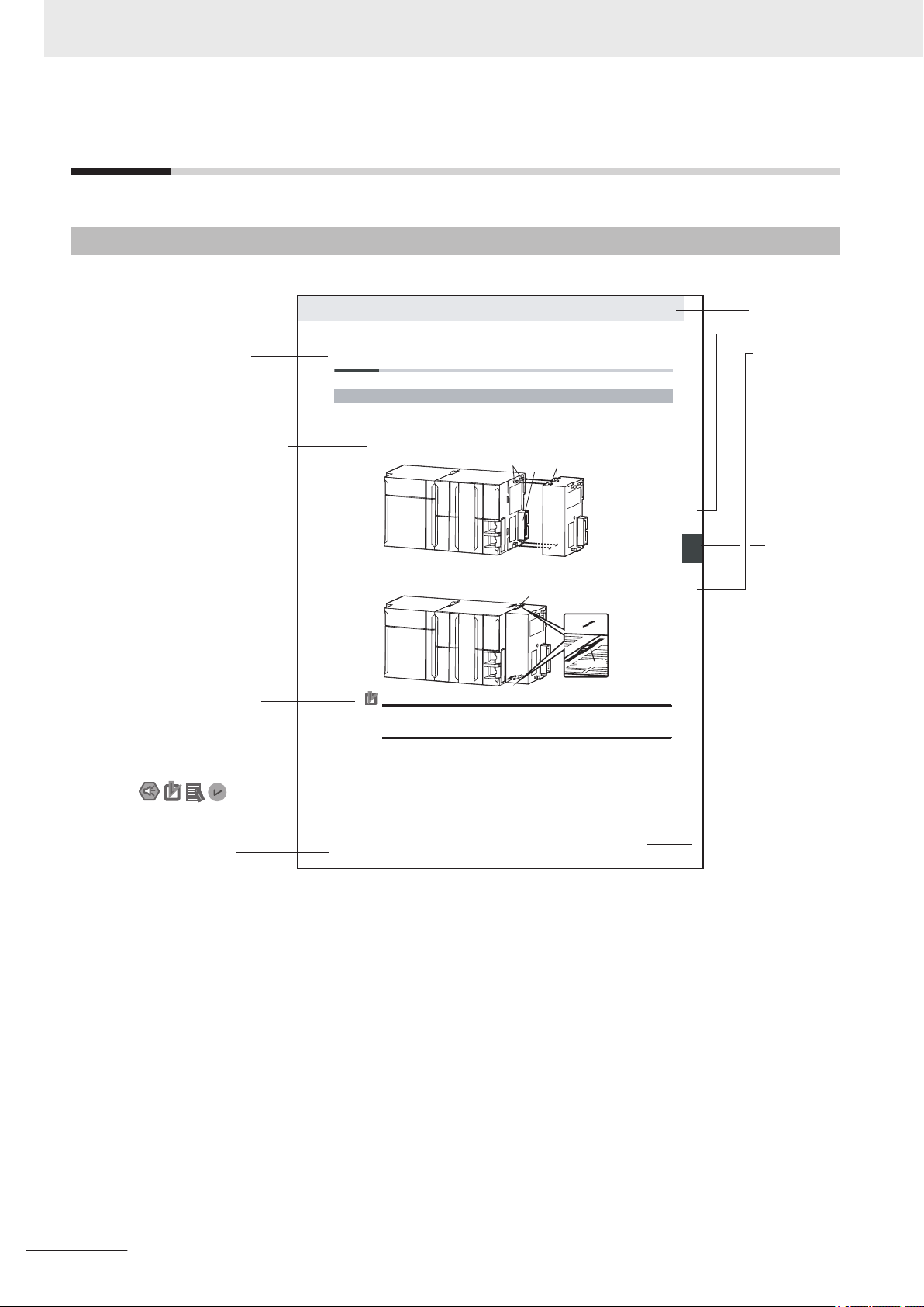
4-3 Mounting Units
The Units that make up an NJ-series Controller can be connected simply by pressing the Units together
and locking the sliders by moving them toward the back of the Units. The End Cover is connected in the
same way to the Unit on the far right side of the Controller.
1 Join the Units so that the connectors fit exactly.
2 The yellow sliders at the top and bottom of each Unit lock the Units together. Move the sliders
toward the back of the Units as shown below until they click into place.
Precautions for Correct UsePrecautions for Correct Use
4-3-1 Connecting Controller Components
Connector
Hook
Hook holes
Slider
Lock
Release
Move the sliders toward the back
until they lock into place.
Level 1 heading
Level 2 heading
Level 3 heading
Level 2 heading
A step in a procedure
Manual name
Special information
Level 3 heading
Page tab
Gives the current
headings.
Indicates a procedure.
Icons indicate
precautions, additional
information, or reference
information.
Gives the number
of the main section.
The sliders on the tops and bottoms of the Power Supply Unit, CPU Unit, I/O Units, Special I/O
Units, and CPU Bus Units must be completely locked (until they click into place) after connecting
the adjacent Unit connectors.
Manual Structure
Manual Structure
Page Structure
The following page structure is used in this manual.
Note : This page is a sample for the purpose of describing the page structure. It differs in its actual content.
2
Autofocus Multicode Reader MicroHAWK V320-F/V330-F/V420-F/V430-F Series User Manual for Communication Settings (Z407-E1)
Page 5

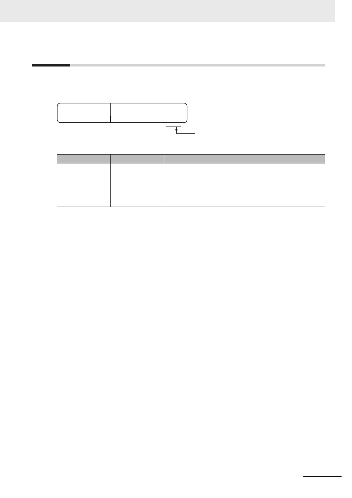
Icons
Manual Structure
The icons used in this manual have the following meanings.
Precautions for Safe Use
Precautions on what to do and what to avoid doing to ensure the safe use of the product.
Precautions for Correct Use
Precautions on what to do and what to avoid doing to ensure proper operation and performance.
Additional Information
Additional information to read as required.
This information is provided to increase understanding or make operation easier.
Autofocus Multicode Reader MicroHAWK V320-F/V330-F/V420-F/V430-F Series User Manual for Communication Settings (Z407-E1)
3
Page 6

Manual Structure
4
Autofocus Multicode Reader MicroHAWK V320-F/V330-F/V420-F/V430-F Series User Manual for Communication Settings (Z407-E1)
Page 7
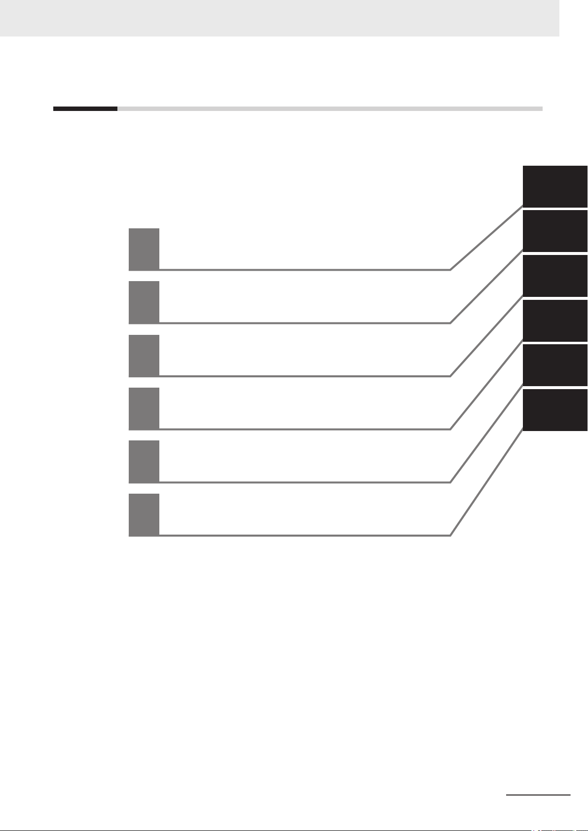
Sections in this Manual
1
2
3
4
5
1
2
3
4
5
Communication Specifications Overview
Controlling Operation and Data Output
with Parallel I/O
Controlling Operation and Data Output
with Ethernet
Controlling Operation and Data Output
with PROFINET
Controlling Operation and Data Output
with RS-232C
A
A
Appendices
Sections in this Manual
Autofocus Multicode Reader MicroHAWK V320-F/V330-F/V420-F/V430-F Series User Manual for Communication Settings (Z407-E1)
5
Page 8

CONTENTS
CONTENTS
Introduction .............................................................................................................. 1
Intended Audience...........................................................................................................................................1
Applicable Products ......................................................................................................................................... 1
Manual Structure...................................................................................................... 2
Page Structure.................................................................................................................................................2
Icons ................................................................................................................................................................3
Sections in this Manual ........................................................................................... 5
Terms and Conditions Agreement.......................................................................... 9
Warranty, Limitations of Liability ......................................................................................................................9
Application Considerations ............................................................................................................................10
Disclaimers ....................................................................................................................................................10
Safety Precautions................................................................................................. 12
Precautions for Safe Use ...................................................................................... 13
Precautions for Correct Use ................................................................................. 14
Regulations and Standards .................................................................................. 15
Related Manuals..................................................................................................... 16
Revision History..................................................................................................... 17
Section 1 Communication Specifications Overview
1-1 Confirming the System Configuration ................................................................................. 1-2
1-1-1 V430-F Series System Configuration..........................................................................................1-2
1-1-2 V420-F Series System Configuration..........................................................................................1-4
1-1-3 V330-F Series System Configuration..........................................................................................1-5
1-1-4 V320-F Series System Configuration..........................................................................................1-6
1-2 Communicating with an External Device.............................................................................1-7
1-2-1 Basic Control Operations of the Code Reader............................................................................1-7
1-2-2 Applicable Communications Protocols for the MicroHAWK V320-F/V330-F/V420-F/
V430-F Series .............................................................................................................................1-8
Section 2 Controlling Operation and Data Output with Parallel I/O
2-1 Controlling Operation and Data Output with Parallel I/O ................................................... 2-2
2-1-1 Basic Operation with a Parallel I/O Connection ..........................................................................2-2
2-1-2 Wiring and Electrical Specifications for Parallel I/O (for V430-F)................................................2-4
2-1-3 Change the Behavior of Operation..............................................................................................2-6
2-1-4 Change the Type of Trigger.........................................................................................................2-7
2-1-5 Timing Charts for each Trigger Mode..........................................................................................2-8
2-1-6 Sample Ladder Program .............................................................................................................2-9
2-1-7 Change the Assignments for the Output Signal (Output 1 to 3) ON Condition .........................2-10
2-1-8 Change the ON/OFF Timing of the Output Signal (Output 1 to 3) ............................................2-20
2-1-9 Change the Polarity of Output Signal (Output 1 to 3)................................................................2-23
2-1-10 Controlling Operation with Signals from an External Device.....................................................2-24
6
Autofocus Multicode Reader MicroHAWK V320-F/V330-F/V420-F/V430-F Series User Manual for Communication Settings (Z407-E1)
Page 9

CONTENTS
Section 3 Controlling Operation and Data Output with Ethernet
3-1 Controlling Operation and Data Output with EtherNet/IP ..................................................3-2
3-1-1 EtherNet/IP Overview..................................................................................................................3-2
3-1-2 Communication with the Code Reader over EtherNet/IP Connection.........................................3-4
3-1-3 Communication Flow Between PLC and Code Reader ..............................................................3-5
3-1-4 Communication Settings (EtherNet/IP) .......................................................................................3-6
3-1-5 Tag Data Link Setting Methods ...................................................................................................3-8
3-1-6 Status and Control Signals for Each Input and Output Assembly............................................. 3-11
3-1-7 Timing Charts by Assembly Type ..............................................................................................3-12
3-1-8 Sample Ladder Program ...........................................................................................................3-14
3-1-9 Accessing the NJ-series Controller Communication Areas using Variables ............................3-15
3-1-10 Communicating with the Code Reader with EtherNet/IP Message...........................................3-28
3-2 Controlling Operation and Data Output with Serial (TCP) ...............................................3-30
3-2-1 Serial (TCP) Overview ..............................................................................................................3-30
3-2-2 Communications Processing Flow ............................................................................................3-30
3-2-3 Communication Settings (Serial (TCP)) ....................................................................................3-31
3-2-4 Setting the Data to Output after a Read....................................................................................3-33
3-2-5 Controlling Operation from an External Device.........................................................................3-39
3-2-6 Serial Command List.................................................................................................................3-42
Section 4 Controlling Operation and Data Output with PROFINET
4-1 Overview of PROFINET .........................................................................................................4-2
4-1-1 Types of PROFINET ...................................................................................................................4-2
4-2 Code Reader Communications for PROFINET Connections.............................................4-5
4-2-1 Types of Communications Areas ................................................................................................4-5
4-3 Setting Up PROFINET Communications..............................................................................4-7
4-3-1 Configuring Network Settings in the Code Reader .....................................................................4-7
4-4 Timing Charts by Module Type ...........................................................................................4-11
4-4-1 Read is Executed by the Read (TRIG) Signal........................................................................... 4-11
4-5 Sample Ladder Program .....................................................................................................4-13
Section 5 Controlling Operation and Data Output with RS-232C
5-1 Controlling Operation and Data Output with RS-232C.......................................................5-2
5-1-1 Communications Processing Flow ..............................................................................................5-2
5-1-2 RS-232C Wiring ..........................................................................................................................5-2
5-1-3 Communication Settings (Serial (RS-232C)) ..............................................................................5-4
5-1-4 Setting Data to be Output after Reading a Code (Serial (RS-232C))..........................................5-7
5-1-5 Additional Symbol Information that can be Appended (Serial (RS-232C)) .................................5-7
5-1-6 Controlling Operation with Serial (RS-232C) from an External Device .......................................5-8
5-1-7 Serial Command List (RS-232C).................................................................................................5-8
Appendices
A-1 Command List ....................................................................................................................... A-2
A-1-1 Command List ............................................................................................................................ A-2
A-2 EtherNet/IP Specifications ................................................................................................... A-3
A-2-1 EDS Files by Firmware Version ................................................................................................. A-3
A-2-2 Assembly Memory Allocation ..................................................................................................... A-3
A-3 PROFINET - V430-F/V330-F Input and Output Modules .................................................. A-31
A-3-1 Module Types........................................................................................................................... A-31
A-3-2 Data Types............................................................................................................................... A-32
A-3-3 PROFINET Base Information................................................................................................... A-33
Autofocus Multicode Reader MicroHAWK V320-F/V330-F/V420-F/V430-F Series User Manual for Communication Settings (Z407-E1)
7
Page 10

CONTENTS
A-3-4 Timing Diagrams ...................................................................................................................... A-34
8
Autofocus Multicode Reader MicroHAWK V320-F/V330-F/V420-F/V430-F Series User Manual for Communication Settings (Z407-E1)
Page 11

Terms and Conditions Agreement
Terms and Conditions Agreement
Warranty, Limitations of Liability
Warranties
Exclusive Warranty
Omron’s exclusive warranty is that the Products will be free from defects in materials and workmanship for a period of twelve months from the date of sale by Omron (or such other period expressed in writing by Omron). Omron disclaims all other warranties, express or implied.
Limitations
OMRON MAKES NO WARRANTY OR REPRESENTATION, EXPRESS OR IMPLIED, ABOUT
NON-INFRINGEMENT, MERCHANTABILITY OR FITNESS FOR A PARTICULAR PURPOSE OF
THE PRODUCTS. BUYER ACKNOWLEDGES THAT IT ALONE HAS DETERMINED THAT THE
PRODUCTS WILL SUITABLY MEET THE REQUIREMENTS OF THEIR INTENDED USE.
Omron further disclaims all warranties and responsibility of any type for claims or expenses based
on infringement by the Products or otherwise of any intellectual property right.
Buyer Remedy
Omron’s sole obligation hereunder shall be, at Omron’s election, to (i) replace (in the form originally
shipped with Buyer responsible for labor charges for removal or replacement thereof) the non-complying Product, (ii) repair the non-complying Product, or (iii) repay or credit Buyer an amount equal
to the purchase price of the non-complying Product; provided that in no event shall Omron be responsible for warranty, repair, indemnity or any other claims or expenses regarding the Products
unless Omron’s analysis confirms that the Products were properly handled, stored, installed and
maintained and not subject to contamination, abuse, misuse or inappropriate modification. Return
of any Products by Buyer must be approved in writing by Omron before shipment. Omron Companies shall not be liable for the suitability or unsuitability or the results from the use of Products in
combination with any electrical or electronic components, circuits, system assemblies or any other
materials or substances or environments. Any advice, recommendations or information given orally
or in writing, are not to be construed as an amendment or addition to the above warranty.
See http://www.omron.com/global/ or contact your Omron representative for published information.
Limitation on Liability; Etc
OMRON COMPANIES SHALL NOT BE LIABLE FOR SPECIAL, INDIRECT, INCIDENTAL, OR CONSEQUENTIAL DAMAGES, LOSS OF PROFITS OR PRODUCTION OR COMMERCIAL LOSS IN ANY
Autofocus Multicode Reader MicroHAWK V320-F/V330-F/V420-F/V430-F Series User Manual for Communication Settings (Z407-E1)
9
Page 12

Terms and Conditions Agreement
WAY CONNECTED WITH THE PRODUCTS, WHETHER SUCH CLAIM IS BASED IN CONTRACT,
WARRANTY, NEGLIGENCE OR STRICT LIABILITY.
Further, in no event shall liability of Omron Companies exceed the individual price of the Product on
which liability is asserted.
Application Considerations
Suitability of Use
Omron Companies shall not be responsible for conformity with any standards, codes or regulations
which apply to the combination of the Product in the Buyer’s application or use of the Product. At Buyer’s request, Omron will provide applicable third party certification documents identifying ratings and
limitations of use which apply to the Product. This information by itself is not sufficient for a complete
determination of the suitability of the Product in combination with the end product, machine, system, or
other application or use. Buyer shall be solely responsible for determining appropriateness of the particular Product with respect to Buyer’s application, product or system. Buyer shall take application responsibility in all cases.
NEVER USE THE PRODUCT FOR AN APPLICATION INVOLVING SERIOUS RISK TO LIFE OR
PROPERTY OR IN LARGE QUANTITIES WITHOUT ENSURING THAT THE SYSTEM AS A WHOLE
HAS BEEN DESIGNED TO ADDRESS THE RISKS, AND THAT THE OMRON PRODUCT(S) IS
PROPERLY RATED AND INSTALLED FOR THE INTENDED USE WITHIN THE OVERALL EQUIPMENT OR SYSTEM.
Programmable Products
Omron Companies shall not be responsible for the user’s programming of a programmable Product, or
any consequence thereof.
Disclaimers
Performance Data
Data presented in Omron Company websites, catalogs and other materials is provided as a guide for
the user in determining suitability and does not constitute a warranty. It may represent the result of
Omron’s test conditions, and the user must correlate it to actual application requirements. Actual performance is subject to the Omron’s Warranty and Limitations of Liability.
10
Change in Specifications
Product specifications and accessories may be changed at any time based on improvements and other reasons. It is our practice to change part numbers when published ratings or features are changed,
or when significant construction changes are made. However, some specifications of the Product may
Autofocus Multicode Reader MicroHAWK V320-F/V330-F/V420-F/V430-F Series User Manual for Communication Settings (Z407-E1)
Page 13

Terms and Conditions Agreement
be changed without any notice. When in doubt, special part numbers may be assigned to fix or establish key specifications for your application. Please consult with your Omron’s representative at any
time to confirm actual specifications of purchased Product.
Errors and Omissions
Information presented by Omron Companies has been checked and is believed to be accurate; however, no responsibility is assumed for clerical, typographical or proofreading errors or omissions.
Autofocus Multicode Reader MicroHAWK V320-F/V330-F/V420-F/V430-F Series User Manual for Communication Settings (Z407-E1)
11
Page 14

Safety Precautions
Safety Precautions
For details on Safety Precautions, please refer to Safety Precautions in Autofocus Multicode Reader
MicroHAWK V320-F/V330-F/V420-F/V430-F Series User Manual (Z432-E).
12
Autofocus Multicode Reader MicroHAWK V320-F/V330-F/V420-F/V430-F Series User Manual for Communication Settings (Z407-E1)
Page 15

Precautions for Safe Use
For details on Precautions for Safe Use, please refer to Precautions for Safe Use in Autofocus
Multicode Reader MicroHAWK V320-F/V330-F/V420-F/V430-F Series User Manual (Z432-E).
Precautions for Safe Use
Autofocus Multicode Reader MicroHAWK V320-F/V330-F/V420-F/V430-F Series User Manual for Communication Settings (Z407-E1)
13
Page 16

Precautions for Correct Use
Precautions for Correct Use
For detailed precautions on the correct use of the product, please refer to Precautions for Correct Use
in Autofocus Multicode Reader MicroHAWK V320-F/V330-F/V420-F/V430-F Series User Manual
(Z432-E).
14
Autofocus Multicode Reader MicroHAWK V320-F/V330-F/V420-F/V430-F Series User Manual for Communication Settings (Z407-E1)
Page 17

Regulations and Standards
For details on Regulations and Standards, please refer to Regulations and Standards in Autofocus
Multicode Reader MicroHAWK V320-F/V330-F/V420-F/V430-F Series User Manual (Z432-E).
Regulations and Standards
Autofocus Multicode Reader MicroHAWK V320-F/V330-F/V420-F/V430-F Series User Manual for Communication Settings (Z407-E1)
15
Page 18

Related Manuals
Related Manuals
The followings are the manuals related to this manual. Use these manuals for reference.
Name of Manual Cat. No. Model Usage Description
MicroHAWK V320-F/V330-F/
V420-F/V430-F Series Autofocus Multicode Reader
User Manual
MicroHAWK V320-F/V330-F/
V420-F/V430-F Series Autofocus Multicode Reader
User Manual for Communications Settings
Z432 MicroHAWK V320-
F/V330-F/V420-F/
V430-F Series
Z407 When you want to
When you want to
know the product
specifications and
basic settings for using the MicroHAWK
V320-F/V330-F/
V420-F/V430-F Series Autofocus Multicode Reader
operate the MicroHAWK V320-F/V330F/V420-F/V430-F
Series Autofocus
Multicode Reader
from an external device
MicroHAWK V320-F/V330-F/V420-F/V430F Series specifications, getting started, explanation of settings, command parameters.
It describes the system configuration, control methods, I/O specifications, supported
network types and communication setting
for using the MicroHAWK V320-F/V330-F/
V420-F/V430-F Series.
16
Autofocus Multicode Reader MicroHAWK V320-F/V330-F/V420-F/V430-F Series User Manual for Communication Settings (Z407-E1)
Page 19
Revision History
Z407-E1-04
Revision code
Cat. No.
A manual revision code appears as a suffix to the catalog number on the front and back covers of the
manual.
Revision Code Date Revised Content
01 Dec. 2018
02 Apr. 2019
03 Dec. 2020
04 Mar. 2021
Revision History
• First Publication.
• Addition of PROFINET content.
• Corresponding to changes to new models of V430-F.
• Added information on the V320-F / V330-F / V420-F Series.
• General improvements.
Autofocus Multicode Reader MicroHAWK V320-F/V330-F/V420-F/V430-F Series User Manual for Communication Settings (Z407-E1)
17
Page 20

Revision History
18
Autofocus Multicode Reader MicroHAWK V320-F/V330-F/V420-F/V430-F Series User Manual for Communication Settings (Z407-E1)
Page 21

1
Communication Specifications
Overview
This section provides a basic overview of the communications specifications and
methods for controlling the code readers. This information is required before performing communications between the MicroHAWK V320-F/V330-F/V420-F/V430-F Series
and an external device.
1-1 Confirming the System Configuration .........................................................1-2
1-1-1 V430-F Series System Configuration .............................................................. 1-2
1-1-2 V420-F Series System Configuration .............................................................. 1-4
1-1-3 V330-F Series System Configuration .............................................................. 1-5
1-1-4 V320-F Series System Configuration .............................................................. 1-6
1-2 Communicating with an External Device..................................................... 1-7
1-2-1 Basic Control Operations of the Code Reader ................................................ 1-7
1-2-2 Applicable Communications Protocols for the MicroHAWK V320-F/
V330-F/V420-F/V430-F Series........................................................................ 1-8
1
Autofocus Multicode Reader MicroHAWK V320-F/V330-F/V420-F/V430-F Series User Manual for Communication Settings (Z407-E1)
1-1
Page 22
I/O control PLC
I/O cable
V430-W8-3M
Basic configuration
Code Reader (V430-F)
External devices
Trigger sensor
WebLink or ESP
*1
Computer
Special Ethernet cable
V430-WE-3M
Switching hub
for EtherNet/IP
(industrial
Ethernet)
*1
Basic configuration
Code Reader (V430-F)
I/O control PLC
I/O cable
V430-W8-3M
Trigger sensor
Special Ethernet cable
V430-WE-3M
General-purpose
Ethernet cable
XS6W-5PUR8SS100CM-G
General-purpose
Ethernet cable
XS6W-5PUR8SS100CM-G
WebLink or ESP
Computer
External devices
1 Communication Specifications Overview
1-1
1-1-1
Confirming the System Configuration
This product is a multi-code reader that captures images of 1D symbols (barcodes) and 2D Symbols
and reads and processes their embedded data.
In a system configuration in which it is connected to a PLC, PC, or other external device, serial commands can be received from, and code reading results can be output to the external device.
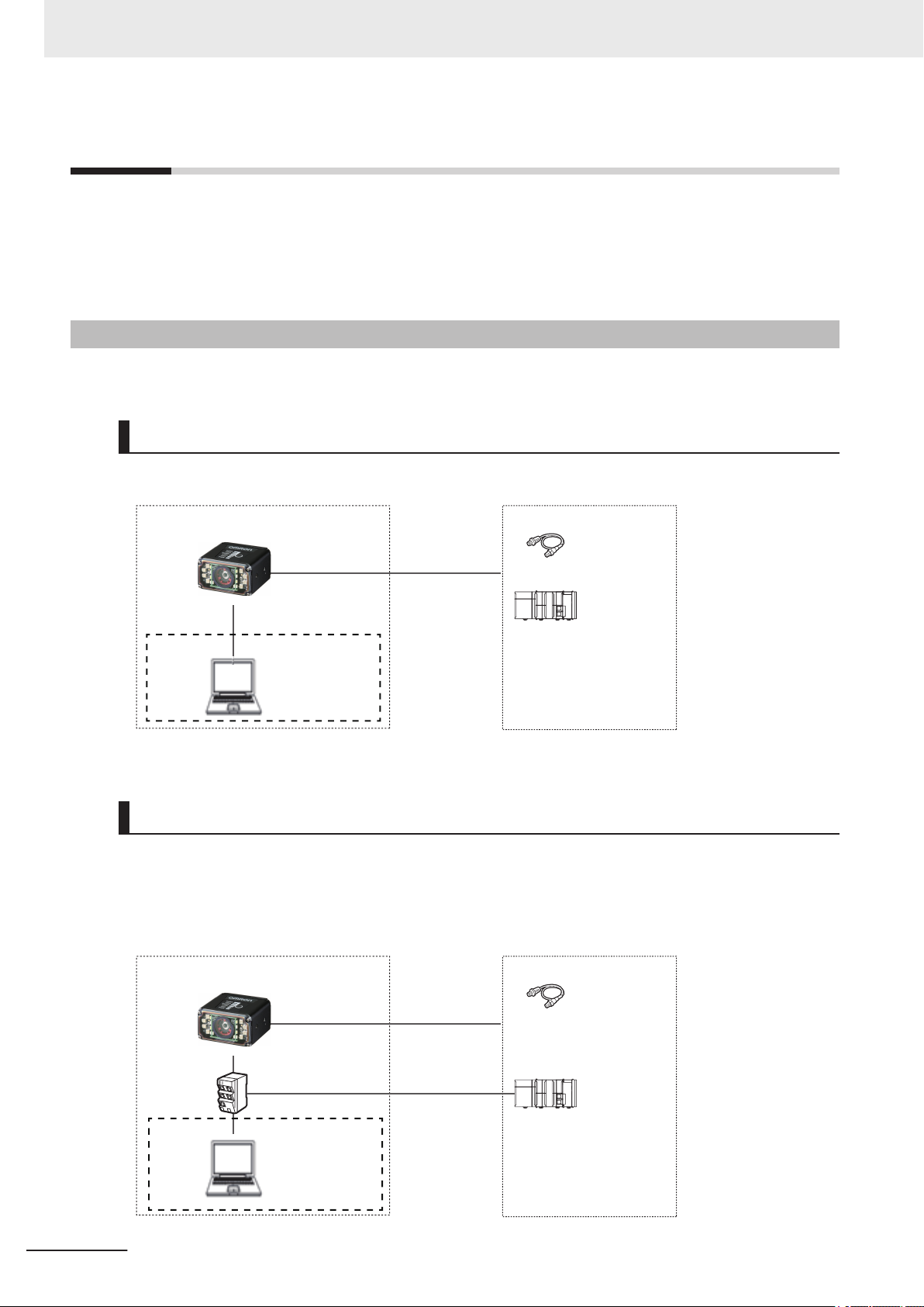
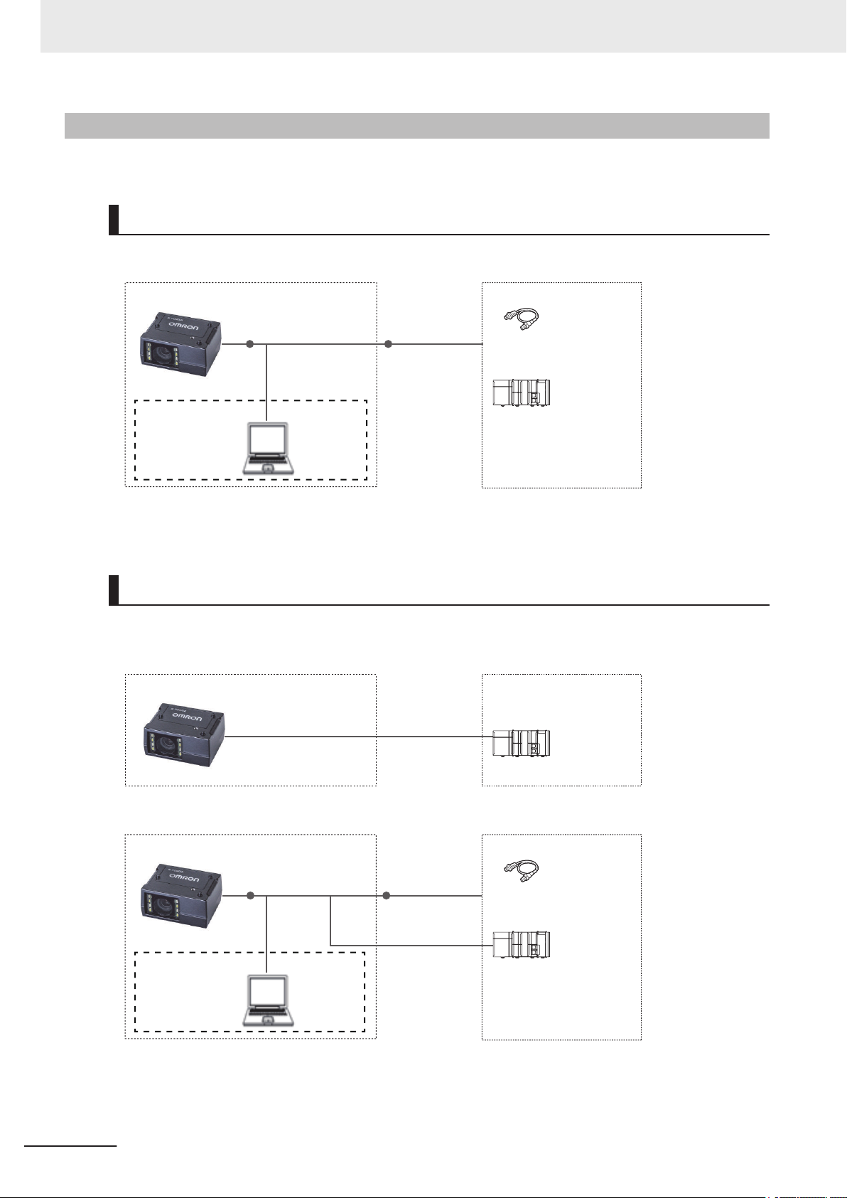
V430-F Series System Configuration
The V430-F can be used in the following types of system configurations.
Connection using Parallel I/O Interface
Trigger inputs and OK/NG Judgement result outputs are received and sent over I/O cable.
1-2
*1 If monitor display is not required, it is not necessary to connect with a PC during operation.
Connecting over Ethernet (EtherNet/IP, Serial (TCP), PROFINET)
Establish network connections via an Ethernet cable to input triggers and communication commands
and to output reading results (Judgment results and decoded content). Triggers can also be input over
parallel I/O. Using the data link function for each network (excluding Serial), data transfer can be done
periodically between the code reader and the external device.
Autofocus Multicode Reader MicroHAWK V320-F/V330-F/V420-F/V430-F Series User Manual for Communication Settings (Z407-E1)
Page 23
Special I/O cable
V430-W8-3M
Code Reader (V430-F)
RS-232C- I/O
2-way cable
V430-WQR-3M
*1
Basic configuration External devices
I/O control PLC
Trigger sensor
Special Ethernet cable
V430-WE-3M
WebLink or ESP
Computer
1 Communication Specifications Overview
*1 If monitor display is not required, it is not necessary to connect with a PC during operation.
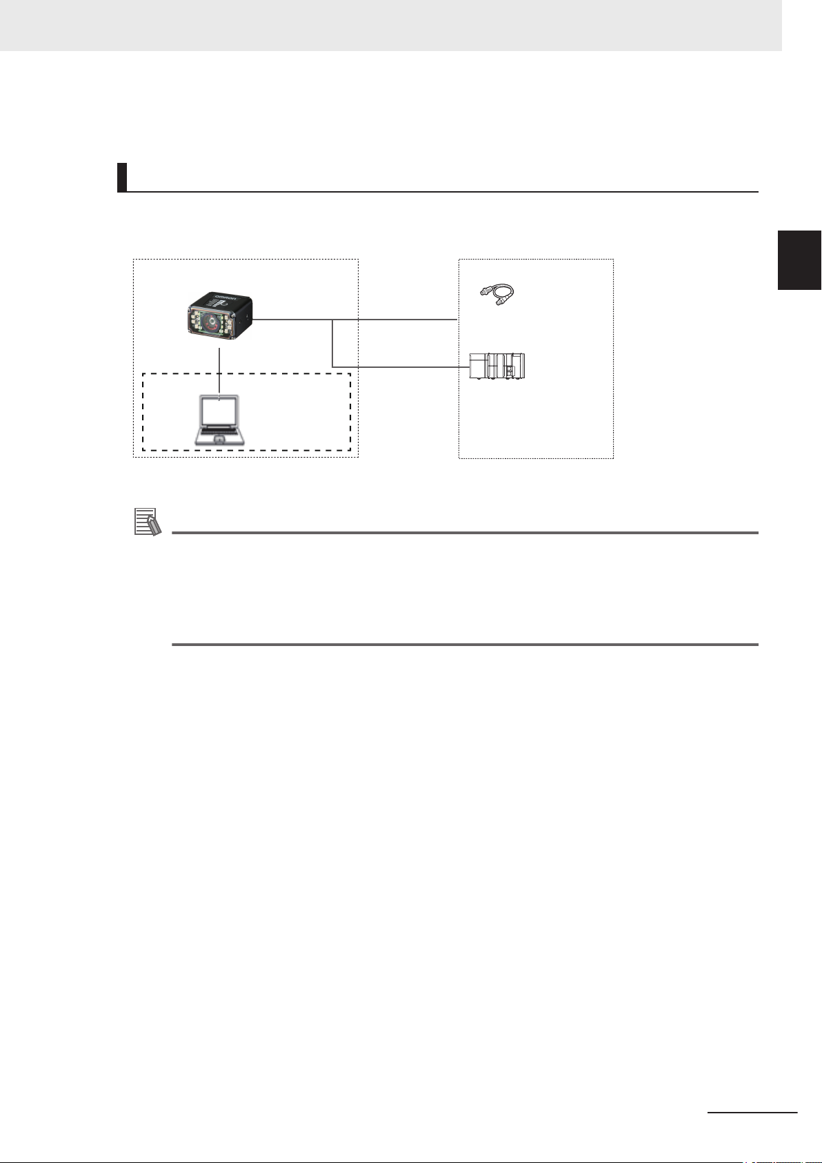
Connecting by Serial (RS-232)
Triggers and Serial command input, as well as Read result judgement and Read string content data
output is transmitted over RS-232C cable. Triggers can also be input over parallel I/O.
1-1 Confirming the System Con-
figuration
1
1-1-1 V430-F Series System Configuration
*1 If monitor display is not required, it is not necessary to connect with a PC during operation.
Additional Information
The cable to use for Serial (RS-232C) communication is RS-232C- I/O 2-way cable (V430WQR-3M) specifically for the V430-F / V440-F. Please use this cable when connecting to a PC
by RS-232C.
For wiring different from that of IBM compatible PC, either make your own converter cable, or
use the discrete wire cable type (V430-W8£ Series) with its RxD signal and TxD signal converted.
Autofocus Multicode Reader MicroHAWK V320-F/V330-F/V420-F/V430-F Series User Manual for Communication Settings (Z407-E1)
1-3
Page 24
*1
Basic configuration
Code Reader (V420-F)
I/O control PLC
I/O cable
61-000151-01
Trigger sensor
Special DB-15 - USB/
I/O cable
V420-WU8X-1M
*2
WebLink or ESP
Computer
External devices
Basic configuration
Code Reader (V420-F)
I/O control PLC
Special DB-15 - RS-232C
cable
V420-WRX-1M
*1
External devices
*1
Basic configuration
Code Reader (V420-F)
I/O control PLC
I/O cable
61-000151-01
Trigger sensor
Special DB-15 - RS-232C/
USB/ I/O cable
V420-WRU8X-1M
*2
WebLink or ESP
Computer
External devices
1 Communication Specifications Overview
1-1-2
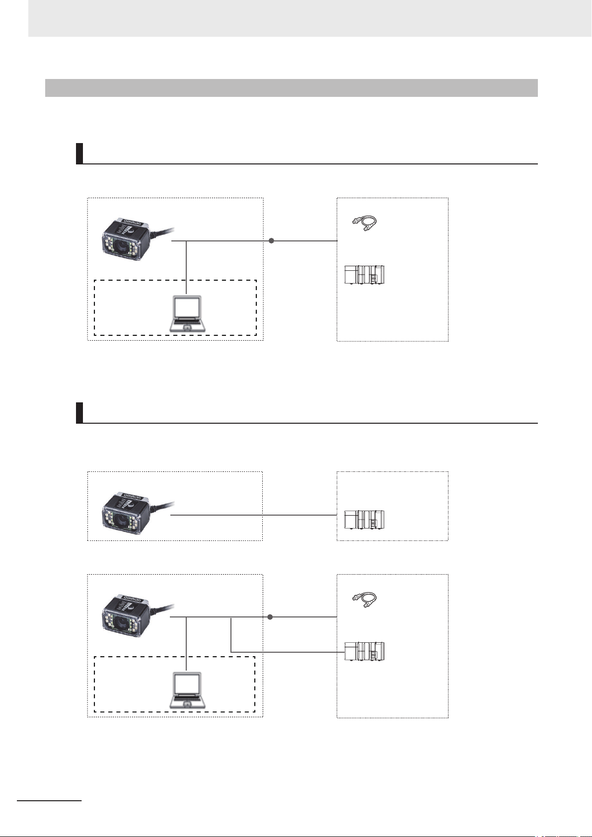
V420-F Series System Configuration
V420-F can be used in the following types of system configurations.
Connection using Parallel I/O Interface
Trigger inputs and OK/NG Judgement result outputs are received and sent over I/O cable.
*1 If monitor display is not required, it is not necessary to connect with a PC during operation.
*2 The V420-WU8X-1M requires power supply from the external power source (97-900011-02).
1-4
Connecting by Serial (RS-232)
Triggers and Serial command input, as well as Read result judgement and Read string content data
output is transmitted over RS-232C cable. Triggers can also be input over parallel I/O.
*1 The V420-WRX-1M requires power supply from the external power source (97-900006-01).
*1 If monitor display is not required, it is not necessary to connect with a PC during operation.
*2 The V420-WRU8X-1M requires power supply from the external power source (97-900011-02).
Autofocus Multicode Reader MicroHAWK V320-F/V330-F/V420-F/V430-F Series User Manual for Communication Settings (Z407-E1)
Page 25
Basic configuration
Code Reader (V330-F)
I/O control PLC
PoE injector *2
External devices
Switching hub
for EtherNet/IP
(industrial
Ethernet)
*1
General-purpose
Ethernet cable
XS6W-5PUR8SS100CM-G
General-purpose
Ethernet cable
XS6W-5PUR8SS100CM-G
General-purpose
Ethernet cable
XS6W-5PUR8SS100CM-G
General-purpose
Ethernet cable
XS6W-5PUR8SS100CM-G
WebLink or ESP
Computer
1 Communication Specifications Overview
1-1 Confirming the System Con-
1-1-3
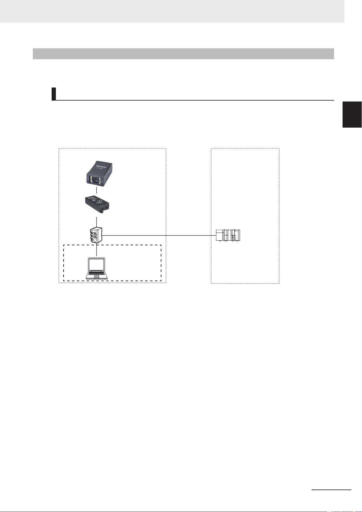
V330-F Series System Configuration
The V330-F can be used in the following types of system configurations.
Connecting over Ethernet (EtherNet/IP, Serial (TCP), PROFINET)
Establish network connections via an Ethernet cable to input triggers and communication commands
and to output reading results (judgment results and decoded content). Using the data link function for
each network (excluding Serial), data transfer can be done periodically between the code reader and
the external device.
figuration
1
1-1-3 V330-F Series System Configuration
*1 If monitor display is not required, it is not necessary to connect with a PC during operation.
*2 The PoE injector requires power supply from an external power source.
Autofocus Multicode Reader MicroHAWK V320-F/V330-F/V420-F/V430-F Series User Manual for Communication Settings (Z407-E1)
1-5
Page 26
*1
Basic configuration
Code Reader (V320-F)
I/O control PLC
I/O cable
61-000151-01
Trigger sensor
Special DB-15 - USB/
I/O cable
V420-WU8X-1M
*2
Special RJ50 - DB-15 cable
V320-WR-1M
WebLink or ESP
Computer
External devices
Basic configuration
Code Reader (V320-F)
I/O control PLC
Special RJ50 - RS-232C cable
V320-WRX-2M
*1
External devices
*1
Basic configuration
Code Reader (V320-F)
I/O control PLC
I/O cable
61-000151-01
Trigger sensor
Special RJ50 - DB-15 cable
V320-WR-1M
Special DB-15
- RS-232C/ USB/
I/O cable
V420-WRU8X-1M
*2
WebLink or ESP
Computer
External devices
1 Communication Specifications Overview
1-1-4
V320-F Series System Configuration
The V320-F can be used in the following types of system configurations.
Connection using Parallel I/O Interface
Trigger inputs and OK/NG Judgement result outputs are received and sent over I/O cable.
*1 If monitor display is not required, it is not necessary to connect with a PC during operation.
*2 The V420-WU8X-1M requires power supply from the external power source (97-900011-02).
Connecting by Serial (RS-232)
Triggers and Serial command input, as well as Read result judgement and Read string content data
output is transmitted over RS-232C cable. Triggers can also be input over parallel I/O.
*1 The V320-WRX-2M requires power supply from the external power source (97-900006-01).
1-6
*1 If monitor display is not required, it is not necessary to connect with a PC during operation.
*2 The V420-WRU8X-1M requires power supply from the external power source (97-900011-02).
Autofocus Multicode Reader MicroHAWK V320-F/V330-F/V420-F/V430-F Series User Manual for Communication Settings (Z407-E1)
Page 27
Trigger sensor
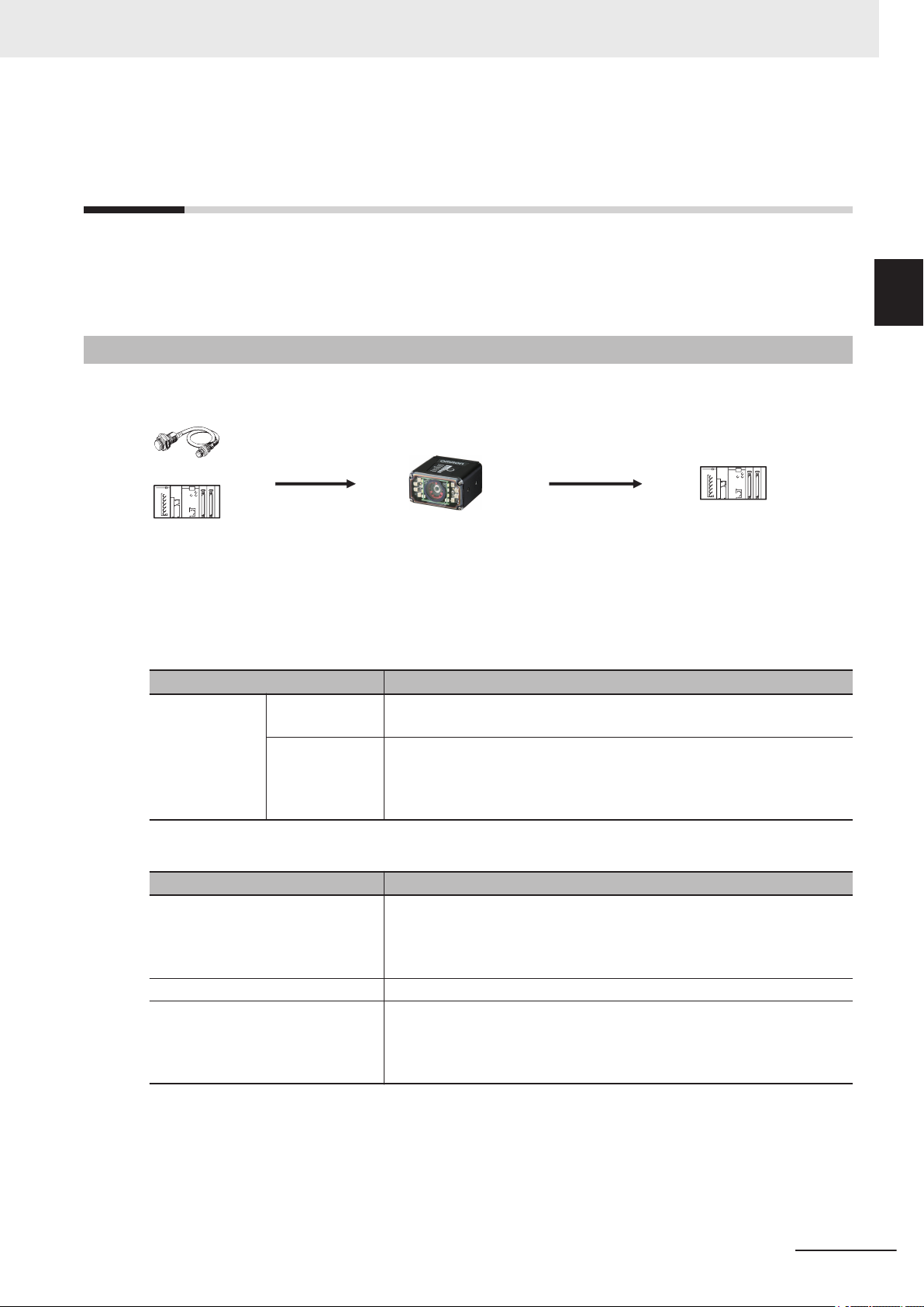
PLC PLC
The reading results are output.
- Status signals
- Read character string output
- Additional information
(read time, quality grade and so on)
Triggers and other
control commands
are input.
Code Reader
1 Communication Specifications Overview
1-2 Communicating with an Ex-
1-2
1-2-1
Communicating with an External Device
This section gives the communications specifications, describes the control methods that you can use
for communications, and describes the settings that are required before starting communications with
an external device.
Basic Control Operations of the Code Reader
The following figure shows basic communications between an external device and the code reader
and the flow of signals and data.
The following methods can be used to exchange data between an external device and the code reader.
ternal Device
1
1-2-1 Basic Control Operations of the Code Reader
Commands that can be input to the code reader from an external device
Type Description
Control Commands
Status Signals When the code reader confirms the input of a control signal or communi-
Read Character String Output You can output the character string read from barcodes, or 2D Codes
Additional Information Additional data such as print quality grade and code position coordinates
Control Signals
(Input Signals)
Communication
Command Input
Data output from the code reader to an external device
Type Description
Reading is executed when a trigger (TRIG signal: ON) is input.
Various commands can be executed, such as a Read commands (trigger)
and commands to change settings.
The communication commands differ depending on the communications
protocol that you use.
cation command and starts the reading process, it notifies the external
device of its status (by signals such as InReadCycle, etc.) and its judgement with the OK/NG Judgment signal.
can be output.
For these items to be appended to the output, they must be setup in advance in the detailed settings menu.
Autofocus Multicode Reader MicroHAWK V320-F/V330-F/V420-F/V430-F Series User Manual for Communication Settings (Z407-E1)
1-7
Page 28
Code Reader (V430-F)
PLC
Computer
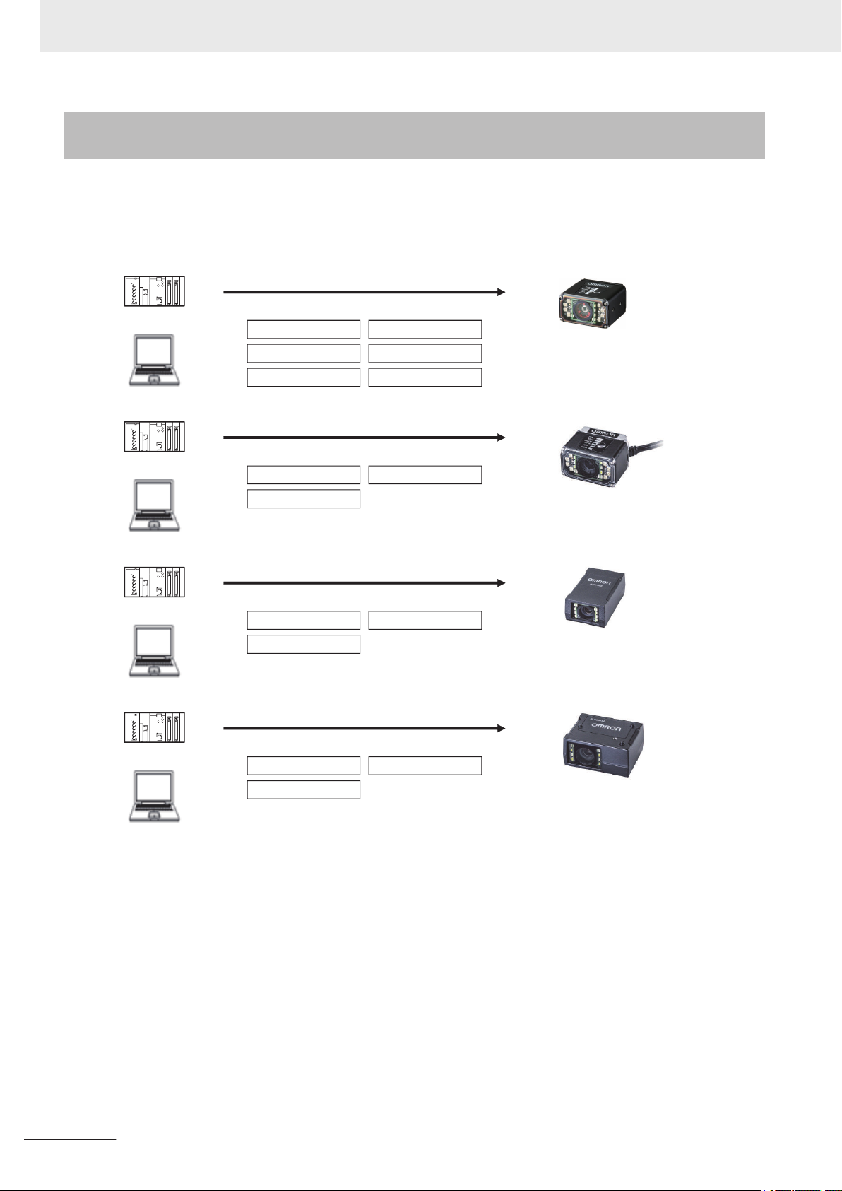
Control can be performed through different communications protocols.
Serial (RS-232C)
EtherNet/IP
PROFINET
USB
Serial (TCP)
Parallel I/O
Code Reader (V420-F)
PLC
Computer
Control can be performed through different communications protocols.
Serial (RS-232C)
USB
Parallel I/O
Code Reader (V330-F)
PLC
Computer
Control can be performed through different communications protocols.
Serial (TCP)
PROFINET
EtherNet/IP
Code Reader (V320-F)
PLC
Computer
Control can be performed through different communications protocols.
Serial (RS-232C)
USB
Parallel I/O
1 Communication Specifications Overview
1-2-2
Applicable Communications Protocols for the MicroHAWK V320F/V330-F/V420-F/V430-F Series
The MicroHAWK V320-F/V330-F/V420-F/V430-F Series can be controlled from a PLC, computer, or
other external device using various communication protocols.
The following types of communication protocols can be used for controlling the MicroHAWK V320-F/
V330-F/V420-F/V430-F Series from an external device.
1-8
Autofocus Multicode Reader MicroHAWK V320-F/V330-F/V420-F/V430-F Series User Manual for Communication Settings (Z407-E1)
Page 29

1 Communication Specifications Overview
1-2 Communicating with an Ex-
Applicable Communications Protocols
Communication
Method
Contact Input Interface
Data Sharing EtherNet/IP This is an open communica-
Frame Transmission Serial (TCP) Command frames are sent to
Communication
Protocol
Parallel I/O Data is exchanged between an
external device and the code
reader through combinations of
ON/OFF signals from multiple
physical contacts.
tions protocol. Tag Data Links
are used for communication
with the code reader. On the
PLC, structured variables are
created that correspond to the
control signals, Command/
Response data, and Read data.
These variables are then used
as I/O Tag Data Links to exchange data between the PLC
and the code reader.
PROFINET This is an open communica-
tions protocol. Software-based
RT (Real-time) communications, (SRT) is used for communication with the code reader.
The control signals, Command
Area/Response Area, and area
to store Read result data are
assigned in the I/O memory of
the PLC, and data is exchanged cyclically between the
PLC and the code reader.
the code reader and Response
frames are received from the
code reader without the use of
any specific protocol.
Data can be exchanged between the PLC, computer, or
other external device and the
code reader in ASCII or binary
format.
Serial (RS-232C) Data can be exchanged in AS-
CII format over the RS-232C
cable connection between the
code reader and its controlling
device (PLC, PC, or other external device).
Description
○: Supported ×: Not supported
Communication Cable Type
Parallel
I/O
Ethernet RS-232C
○ × ×
× ○ ×
× ○ ×
× ○ ×
× × ○
ternal Device
1
1-2-2 Applicable Communications Protocols for the MicroHAWK V320-F/V330-F/V420-F/V430-F Series
Autofocus Multicode Reader MicroHAWK V320-F/V330-F/V420-F/V430-F Series User Manual for Communication Settings (Z407-E1)
1-9
Page 30
1 Communication Specifications Overview
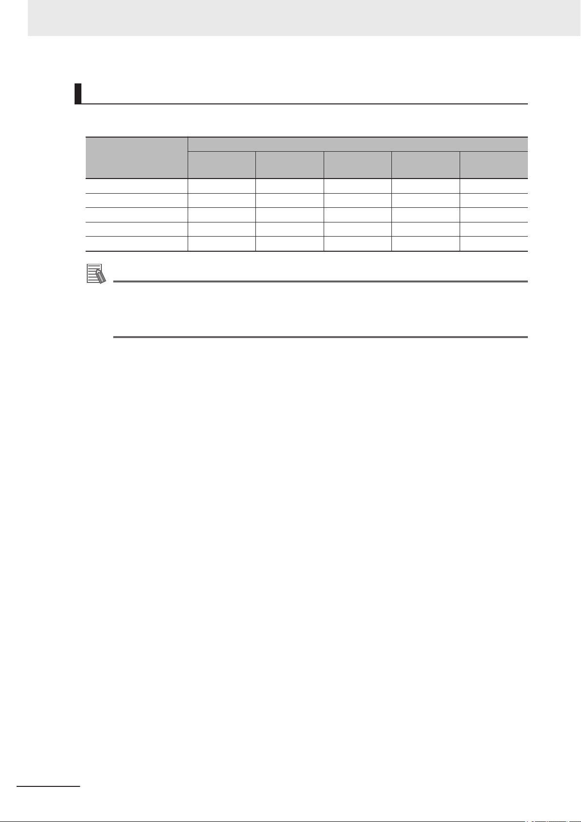
Simultaneous Use of Communication Methods and Connections
○: Supported ×: Not Supported -: N/A
Code reader Connec-
tion Method
EtherNet/IP - × ○ ○ ○
PROFINET × - ○ ○ ○
Serial (TCP) ○ ○ - ○ ○
Serial (RS-232C) ○ ○ ○ - ○
Parallel I/O ○ ○ ○ ○ -
EtherNet/IP PROFINET Serial (TCP)
Simultaneous Connection Method
Serial
(RS-232C)
Parallel I/O
Additional Information
About connections over network routers
WebLink can connect to code readers on different networks across routers.
• To connect to the code reader, enter its IP address from the browser.
• Set a fixed IP address for the code reader you wish to connect to.
1-10
Autofocus Multicode Reader MicroHAWK V320-F/V330-F/V420-F/V430-F Series User Manual for Communication Settings (Z407-E1)
Page 31

2
Controlling Operation and Data
Output with Parallel I/O
2-1 Controlling Operation and Data Output with Parallel I/O ...........................2-2
2-1-1 Basic Operation with a Parallel I/O Connection .............................................. 2-2
2-1-2 Wiring and Electrical Specifications for Parallel I/O (for V430-F) .................... 2-4
2-1-3 Change the Behavior of Operation.................................................................. 2-6
2-1-4 Change the Type of Trigger ............................................................................. 2-7
2-1-5 Timing Charts for each Trigger Mode.............................................................. 2-8
2-1-6 Sample Ladder Program ................................................................................. 2-9
2-1-7 Change the Assignments for the Output Signal (Output 1 to 3) ON
Condition ....................................................................................................... 2-10
2-1-8 Change the ON/OFF Timing of the Output Signal (Output 1 to 3)................. 2-20
2-1-9 Change the Polarity of Output Signal (Output 1 to 3).................................... 2-23
2-1-10 Controlling Operation with Signals from an External Device......................... 2-24
2
Autofocus Multicode Reader MicroHAWK V320-F/V330-F/V420-F/V430-F Series User Manual for Communication Settings (Z407-E1)
2-1
Page 32

Trigger sensor
External devices
(1) Trigger input
Code Reader
(3) Judgement results
are output.
(2) Read is execute.
1. Trigger input
(TRIG signal)
OFF
ON
2. Output1
In Read Cycle
OFF
ON
OFF
ON
3. Output2
Match
(or Good Read)
In Read Cycle
Turns ON on Good Read.
Read executed by Trigger Input.
Length of time to hold the signal
can be changed in settings. *1
OFF
ON
4. Output3
Mismatch
(or No Read)
Turns ON when No Read.
Length of time to hold the signal
can be changed in settings. *1
2 Controlling Operation and Data Output with Parallel I/O
2-1
2-1-1
Controlling Operation and Data Output with Parallel I/O
This section explains how to connect the code reader to an external device by the I/O cable and the
methods that you can use to control the code reader from the external device.
Basic Operation with a Parallel I/O Connection
This section describes the basic connections and signal flow with external devices.
Operation for one of the primary uses is described in the example below.
Example of Trigger Input and OUTPUT signal
Below is an Output assignment example and Timing chart.
[Example assignment of OUTPUT signals]
• Output 1: In Read Cycle
It turns ON while the code reader is in its Read cycle.
• Output 2: On Match (or Good Read)
It turns ON when there is a Good Read or when it matches with the Master Symbol (if using the
Matchcode function).
• Output 3 : On Mismatch (or No Read)
It turns ON when there is a No Read or when it does not match with the Master Symbol (if using the
Matchcode function).
For how to set up the Output signal assignments, please refer to How to Assign the Output Signals on
page 2-12.
<Timing Chart>
2-2
Autofocus Multicode Reader MicroHAWK V320-F/V330-F/V420-F/V430-F Series User Manual for Communication Settings (Z407-E1)
Page 33

2 Controlling Operation and Data Output with Parallel I/O
*1 For how to change the length of time to hold the signal, please refer to 2-1-8 Change the ON/OFF
Timing of the Output Signal (Output 1 to 3) on page 2-20.
2-1 Controlling Operation and Data Output
with Parallel I/O
2
2-1-1 Basic Operation with a Parallel I/O Connection
Autofocus Multicode Reader MicroHAWK V320-F/V330-F/V420-F/V430-F Series User Manual for Communication Settings (Z407-E1)
2-3
Page 34

Code Reader
Brown 24V
Blue 0V
Red COM_IN
Red / Black COM_OUT
White TRIG
Black SD
Purple RD
Gray OUTPUT1
Gray / Red OUTPUT2
Pink OUTPUT3
Green DEFAULT
Yellow NEW MASTER
None (Shield)
2 Controlling Operation and Data Output with Parallel I/O
2-1-2
Wiring and Electrical Specifications for Parallel I/O (for V430-F)
The following is the wiring diagram of the power cable to connect to the V430-F (All V430-W8).
Wire color Pin No. Signal Name Function
Brown 2 24V Power supply
Blue 7 0V GND
Red 8 COM_IN Common Input Signals (Input Common)
Red / Black 12 COM_OUT Common Output Signals (Output Common)
White 1 TRIG Read Trigger Input (Trigger)
Black 9 SD Send Data (SD)
Purple 10 RD Receive Data (RD)
Gray 5 OUTPUT 1 (Output 1)
Gray / Red 11 OUTPUT 2 (Output 2)
Pink 6 OUTPUT 3 (Output 3)
Green 3 DEFAULT (Default)
Yellow 4 NEW MASTER (New Master)
None - - (Shield)
2-4
Autofocus Multicode Reader MicroHAWK V320-F/V330-F/V420-F/V430-F Series User Manual for Communication Settings (Z407-E1)
Page 35

Code reader
NPN device
+V
GND
COM_IN
INPUT
- TRIG
- DEFAULT
- NEW MASTER
CLC
CLC = Current Limiting Circuit
NPN device
GND
COM_OUT
OUTPUT
- OUTPUT1
- OUTPUT2
- OUTPUT3
+V
Input
Code reader
COM_IN
INPUT
- TRIG
- DEFAULT
- NEW MASTER
CLC
CLC = Current Limiting Circuit
+V
GND
Code reader
PNP device
COM_OUT
OUTPUT
- OUTPUT1
- OUTPUT2
- OUTPUT3
GND
+V
Input
Code reader
PNP device
2 Controlling Operation and Data Output with Parallel I/O
• Input circuit diagram (V430-F ↔ External device) when NPN connected
2-1 Controlling Operation and Data Output
with Parallel I/O
2
• Output circuit diagram (V430-F ↔ External device) when NPN connected
• Input circuit diagram (V430-F ↔ External device) when PNP connected
2-1-2 Wiring and Electrical Specifications for Parallel I/O (for V430-F)
Autofocus Multicode Reader MicroHAWK V320-F/V330-F/V420-F/V430-F Series User Manual for Communication Settings (Z407-E1)
• Output circuit diagram (V430-F ↔ External device) when PNP connected
2-5
Page 36

2 Controlling Operation and Data Output with Parallel I/O
2-1-3
Change the Behavior of Operation
The following changes are possible depending on the system configuration and usage.
Type Modification
Change the type of Trigger You can change the method used to trigger a Read
(Triggered, or Continuous).
Change the assignments for the Output Signal (Output
1 to 3) ON Condition
Change the ON/OFF timing of the Output Signal (Output 1 to 3)
Change the Output polarity of Output Signal (Output 1
to 3)
Change the ON condition for Output 1 to 3.
Change the OFF timing of the Output 1 to 3 signals after they turn ON.
Change the Output polarity for Output 1 to 3.
2-6
Autofocus Multicode Reader MicroHAWK V320-F/V330-F/V420-F/V430-F Series User Manual for Communication Settings (Z407-E1)
Page 37

2 Controlling Operation and Data Output with Parallel I/O
2-1 Controlling Operation and Data Output
2-1-4
Change the Type of Trigger
It is possible to change the Input method for the trigger used by the code reader to execute Image
capture.
• WebLink - Setup - Gear Icon - Advanced Settings - Read Cycle - Trigger
Setting Item Setting Value Description
Mode Continuous Read With no Parallel TRIG signal used, the code reader executes Con-
tinuous Read.
The data is continually output as each code is read.
External Trigger Signal Filter (Rising
Edge)
External Trigger Signal Filter (Falling
Edge)
External Trigger
State
Continuous Read 1
Output
External Level While TRIG signal is ON, Read is executed.
External Edge While TRIG signal is ON, Read is executed.
Serial Data Read is executed when you send the serial command "<>" (de-
Serial Data and
Edge
Continuous Read
Auto
0 to 2097120 μs When the TRIG signal is ON for more than a set time, the trigger
0 to 2097120 μs When the TRIG signal is OFF for more than a set time, the trigger
Active Open When the TRIG signal turns from OFF → ON, it is recognized as
Active Closed When the TRIG signal turns from ON → OFF, it is recognized as
With no Parallel TRIG signal used, the code reader executes Continuous Read.
If the data of a read code is the same as the previously read code,
it is not output.
When TRIG signal turns OFF, Read ends.
On Good Read or when End of Read Cycle condition is met,
Read ends.
fault value) to the code reader.
On Good Read or when End of Read Cycle condition is met,
Read ends.
Read is executed when TRIG signal turns ON or when you send
the serial command "<>" (default value) to the code reader.
On Good Read or when End of Read Cycle condition is met,
Read ends.
With no Parallel TRIG signal used, the code reader executes Continuous Read.
Exposure time and Gain is automatically adjusted for every Read
performed.
is input as ON.
If it is ON for less than the set time, it is not regarded as ON, so
no trigger is input.
is input as OFF.
If it is OFF for less than the set time, it is not regarded as OFF, so
no trigger is input.
the rising edge of the Trigger.
When the TRIG signal turns from ON → OFF, it is recognized as
the falling edge of the Trigger.
the rising edge of the Trigger.
When the TRIG signal turns from OFF → ON, it is recognized as
the falling edge of the Trigger.
with Parallel I/O
2
2-1-4 Change the Type of Trigger
Autofocus Multicode Reader MicroHAWK V320-F/V330-F/V420-F/V430-F Series User Manual for Communication Settings (Z407-E1)
2-7
Page 38

1. Trigger input
(TRIG signal)
2. Output1
In Read Cycle
3. Output2
Match
(or Good Read)
4. Output3
Mismatch
(or No Read)
OFF
ON
OFF
ON
OFF
ON
Turns ON on Good Read.
OFF
ON
Read is executed only
while Trigger Input is ON.
Read is executed only
while Trigger Input is ON.
Turns ON when No Read.
2 Controlling Operation and Data Output with Parallel I/O
2-1-5
Timing Charts for each Trigger Mode
There are two methods for Trigger input.
Trigger Input Method Overview Trigger Mode
Triggered Execute Read when the input on
the Parallel TRIG signal is ON.
Continuous Read With no Parallel TRIG signal used,
the code reader executes Continuous Read.
Below is an Output assignment example and Timing chart.
[Example assignment of OUTPUT signals]
• Output 1: In Read Cycle
It turns ON while the code reader is in its Read cycle.
• Output 2: On Match (or Good Read) Output Mode: Pulse
It turns ON when there is a Good Read or when it matches with the master symbol (if using the
Matchcode function).
• Output 3: Mismatch (or on No Read) Output Mode: Pulse
It turns ON when there is a No Read or when it does not match with the master symbol (if using the
Matchcode function).
For how to set up the Output signal assignments, please refer to How to Assign the Output Signals on
page 2-12.
• External Level
• External Edge
• Serial Data
• Continuous Read
• Continuous Read 1 Output
• Continuous Read Auto
<Timing Chart (External Level)>
<Timing Chart (External Edge)>
2-8
Autofocus Multicode Reader MicroHAWK V320-F/V330-F/V420-F/V430-F Series User Manual for Communication Settings (Z407-E1)
Page 39

1. Trigger input
(TRIG signal)
2. Output1
In Read Cycle
3. Output2
Match
(or Good Read)
4. Output3
Mismatch
(or No Read)
OFF
ON
OFF
ON
OFF
ON
In Read Cycle
Turns ON on Good Read.
Read executed by Trigger Input.
OFF
ON
Turns ON when No Read.
1. Trigger input
(TRIG signal)
2. Output1
In Read Cycle
3. Output2
Match
(or Good Read)
4. Output3
Mismatch
(or No Read)
OFF
ON
OFF
ON
In Read Cycle
Turns ON on Good Read.
TRIG Signal not used.
OFF
ON
Turns ON if No Read occurs.
Always in Read Cycle *1
Either Output 2 or Output 3 will
continue as ON.
2 Controlling Operation and Data Output with Parallel I/O
2-1 Controlling Operation and Data Output
with Parallel I/O
2
2-1-6
<Timing Chart (Continuous Read)>
*1 Output 1 turns OFF for about 300 μs at the end of each Read Cycle.
Sample Ladder Program
This is a sample ladder program that inputs the TRIG signal to execute a Triggered Read.
Triggered Read is executed by W0.00 ON.
2-1-6 Sample Ladder Program
Autofocus Multicode Reader MicroHAWK V320-F/V330-F/V420-F/V430-F Series User Manual for Communication Settings (Z407-E1)
2-9
Page 40

SET When the single read command bit (W0.00) turns ON,
the TRIG signal is turned.
The TRIG signal is kept ON for 2 ms and then turned OFF.
TRIG
W0.00
Single read
command bit
OUT1
InReadCycle
signal
0000
#2
TRIG
TRIG signal
TMHH
TRIG
T0000
RSET
W0.00
++L
1000
++L
1002
OUT2
OUT3
OUT1
In Read
Cycle
Match (or Good Read)
Mismatch (or No Read)
The judgement result is added to the total count.
OK: 1000, NG: 1002
RSET
2 Controlling Operation and Data Output with Parallel I/O
2-1-7
Input and Output Signal Assignment
Signal Type Address
Output Signal Output 1 0.00
Output 2 0.01
Output 3 0.02
Input Signal TRIG 1.00
Precautions for Correct Use
The time at which Read is executed is the same time the InReadCycle signal turns ON.
The following Output signal assignments are made in WebLink.
• Output 1: In Read Cycle
• Output 2: On Match or On Good Read Output Mode: Pulse
• Output 3: On Mismatch (or No Read)
For how to set up the Output signal assignments, please refer to How to Assign the Output Signals on
page 2-12.
Change the Assignments for the Output Signal (Output 1 to 3) ON Condition
The condition for turning the Output signals, Output 1, 2, 3 to ON can be set.
The following conditions for output can be set.
Mismatch or No Read It turns ON when there is a No Read or when it does not match with the
Match or Good Read It turns ON when there is a Good Read or when it matches with the Mas-
2-10
Autofocus Multicode Reader MicroHAWK V320-F/V330-F/V420-F/V430-F Series User Manual for Communication Settings (Z407-E1)
Output On Parameter meaning
Master Symbol (if using the Matchcode function).
ter Symbol (if using the Matchcode function).
Page 41

2 Controlling Operation and Data Output with Parallel I/O
Output On Parameter meaning
Mismatch It turns ON when it does not match with the Master Symbol (if using the
Matchcode function). When the Matchcode function is not used, it is always OFF.
No Read It turns ON when there is a No Read result.
Trend Analysis Turns ON when the conditions set for Trend Analysis (Output 1 to 3) are
matched.
Symbol Quality Turns ON when the ISO/IEC xxx Code Quality conditions set for (Output
1 to 3) are met. Select 15415, 15416, 16022, or 29158.
Diagnostic Warning Turns ON when the conditions set for Diagnostics (Output 1 to 3) are met.
In Read Cycle ON while the code reader is in its Read cycle. Confirm the output when it
changes from ON to OFF.
Use as Ext.Illumination Strobe
- Can only be assigned to Output 3.
It is the signal used to illuminate with external lighting
Turns ON when Light Source is set to External Strobe and a Trigger is
input.
2-1 Controlling Operation and Data Output
with Parallel I/O
2
2-1-7 Change the Assignments for the Output Signal (Output 1 to 3) ON Condition
Autofocus Multicode Reader MicroHAWK V320-F/V330-F/V420-F/V430-F Series User Manual for Communication Settings (Z407-E1)
2-11
Page 42

2 Controlling Operation and Data Output with Parallel I/O
How to Assign the Output Signals
The Output signals can be assigned using WebLink.
1 From the WebLink screen, select Setup → Outputs.
2 The Digital Output Editor dialog opens.
3 The Output condition for each Output signal can be set or changed in Output On.
4 Advanced Settings for Trend Analysis, Symbol Quality and Diagnostic Warning are displayed
by clicking on the Text string at the bottom of the Output setting screen. Here you can change
any settings as needed.
2-12
Autofocus Multicode Reader MicroHAWK V320-F/V330-F/V420-F/V430-F Series User Manual for Communication Settings (Z407-E1)
Page 43

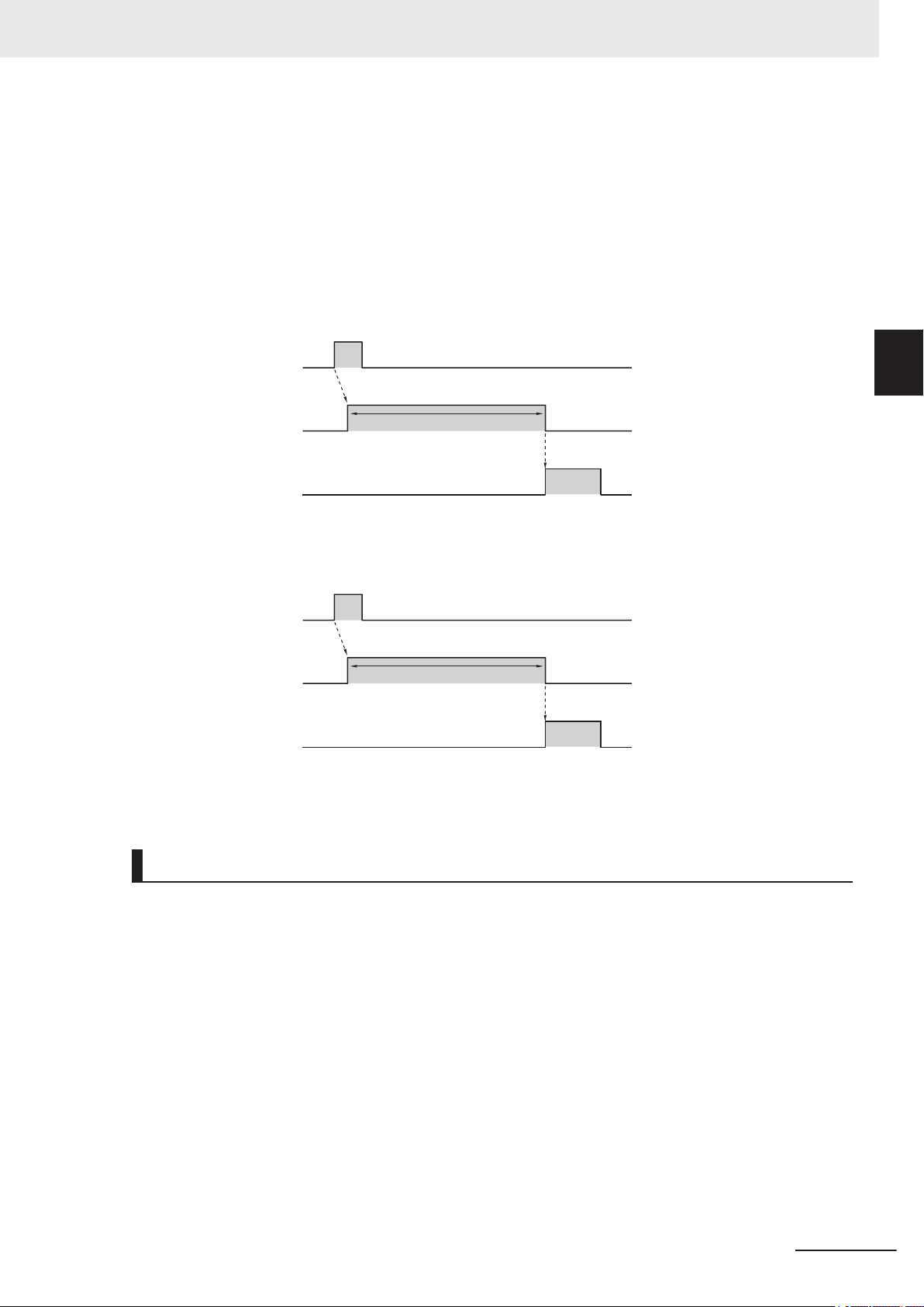
1. Trigger input
(TRIG signal)
2. Output1
In Read Cycle
3. Output2
Mismatch
(or No Read)
OFF
ON
OFF
ON
OFF
ON
In Read Cycle
Turns ON if No Read. *1
Read executed by Trigger Input.
2 Controlling Operation and Data Output with Parallel I/O
Mismatch or No Read
The assigned output signal turns ON when one of the following conditions is met.
• On No Read (NOREAD)
• If using the Matchcode function, when it does not match with the master symbol
• Triggered Mode must be External or Serial
Below is an Output assignment example and Timing chart.
[Example assignment of OUTPUT signals]
• Output 1: In Read Cycle
• Output 2: Mismatch (or No Read) Output Mode: Pulse
For how to set up the Output signal assignments, please refer to How to Assign the Output Signals on
page 2-12.
<Timing Chart>
2-1 Controlling Operation and Data Output
with Parallel I/O
2
2-1-7 Change the Assignments for the Output Signal (Output 1 to 3) ON Condition
*1 You can change the length of time the signal is ON. For further information, please refer to
2-1-8 Change the ON/OFF Timing of the Output Signal (Output 1 to 3) on page 2-20.
Match (or On Good Read)
The assigned output signal turns ON when one of the following conditions is met.
• On Good Read
• If using the Matchcode function, when it matches with the master symbol
Below is an Output assignment example and Timing chart.
[Example assignment of OUTPUT signals]
• Output 1: In Read Cycle
• Output 2: On Match (or On Good Read) Output Mode: Pulse
For how to set up the Output signal assignments, please refer to How to Assign the Output Signals on
page 2-12.
<Timing Chart>
• Trigger Input → On Good Read
Autofocus Multicode Reader MicroHAWK V320-F/V330-F/V420-F/V430-F Series User Manual for Communication Settings (Z407-E1)
2-13
Page 44

1. Trigger input
(TRIG signal)
2. Output1
In Read Cycle
3. Output2
Match
(or Good Read)
OFF
ON
OFF
ON
OFF
ON
In Read Cycle
Turns ON on Good Read *1
Read executed by Trigger Input.
1. Trigger input
(TRIG signal)
2. Output1
In Read Cycle
OFF
ON
OFF
ON
OFF
ON
3. Output2
Mismatch
In Read Cycle
Turns ON on Good Read or Character string Mismatch *1
Read executed by Trigger Input.
2 Controlling Operation and Data Output with Parallel I/O
*1 You can change the length of time the signal is ON. For further information, please refer to
2-1-8 Change the ON/OFF Timing of the Output Signal (Output 1 to 3) on page 2-20.
Mismatching Character String (Mismatch)
If using the Matchcode function, the assigned output signal for a Mismatch with the Master Symbol
turns ON.
When the Matchcode function is not used, the signal state is OFF.
Note
Matchcode functionality is only used when Triggering mode is External or Serial.
Below is an Output assignment example and Timing chart.
[Example assignment of OUTPUT signals]
• Output 1: In Read Cycle
• Output 2: Character string Mismatch Output Mode: Pulse
For how to set up the Output signal assignments, please refer to How to Assign the Output Signals on
page 2-12.
<Timing Chart>
• Trigger Input → No Read (Mismatch with Master Symbol)
*1 You can change the length of time the signal is ON. For further information, please refer to
2-1-8 Change the ON/OFF Timing of the Output Signal (Output 1 to 3) on page 2-20.
2-14
No Read
The assigned Output signal turns ON when there is a No Read.
Note
Triggered mode must be External or Serial.
Below is an Output assignment example and Timing chart.
[Example assignment of OUTPUT signals]
• Output 1: In Read Cycle
• Output 2: No Read Output Mode: Pulse
Autofocus Multicode Reader MicroHAWK V320-F/V330-F/V420-F/V430-F Series User Manual for Communication Settings (Z407-E1)
Page 45

1. Trigger input
(TRIG signal)
2. Output1
In Read Cycle
3. Output2
No Read
OFF
ON
OFF
ON
OFF
ON
In Read Cycle
Turns ON if No Read *1
Read executed by Trigger Input.
1. Trigger input
(TRIG signal)
2. Output1
In Read Cycle
OFF
ON
OFF
ON
In Read Cycle
Read executed by Trigger Input.
2 Controlling Operation and Data Output with Parallel I/O
For how to set up the Output signal assignments, please refer to How to Assign the Output Signals on
page 2-12.
<Timing Chart>
• Trigger Input → On No Read
*1 You can change the length of time the signal is ON. For further information, please refer to
2-1-8 Change the ON/OFF Timing of the Output Signal (Output 1 to 3) on page 2-20.
2-1 Controlling Operation and Data Output
with Parallel I/O
2
2-1-7 Change the Assignments for the Output Signal (Output 1 to 3) ON Condition
In Read Cycle
The assigned output signal turns ON when the code reader is In Read Cycle. The setting selected for
Output Mode is disabled.
This signal turns ON when the Read Cycle starts. The timing for when it turns OFF depends on what is
set for the End of Read Cycle condition.
• When the End of Read Cycle condition is Timeout
On Good Read: Turns OFF when there is a Good Read.
No Read: Turns OFF when the Timeout period is exceeded.
• When the End of Read Cycle condition is Last Frame
On Good Read: Turns OFF when there is a Good Read.
On No Read: Turns OFF when all the image capture executed by 1 trigger input is completed.
• When the End of Read Cycle condition is New Trigger
On Good Read: Turns OFF when there is a Good Read.
On No Read: Turns OFF when a trigger is input and there is a New Read Cycle. At this time, since
the New Read Cycle is in progress, it will turn ON again.
Below is an Output assignment example and Timing chart.
[Example assignment of OUTPUT signals]
• Output 1: In Read Cycle
For how to set up the Output signal assignments, please refer to How to Assign the Output Signals on
page 2-12.
<Timing Chart>
• Trigger input
Autofocus Multicode Reader MicroHAWK V320-F/V330-F/V420-F/V430-F Series User Manual for Communication Settings (Z407-E1)
2-15
Page 46

2 Controlling Operation and Data Output with Parallel I/O
Trend Analysis
Monitors the frequency of Mismatches and No Reads as well as the Number of Reads per Trigger, and
turns ON when a certain threshold is met.
This can be used to monitor quality indicators like the percentage of Matches and Read Rate.
The following settings are set independent for each Output signal.
Change the Output signal number selection as needed for your application.
• WebLink - Setup - Gear Icon - Advanced Settings - I/O - Trend Options (Output 1, 2, 3)
Setting Item Setting Value Description
Trend Analysis
Mode
Number of Triggers 0 to 255 The number of triggers in the Trend Analysis.
Number to OutputOn0 to 255 This is the threshold for turning on the Output signal Trend Analy-
Decodes per Trigger
Threshold
• Mismatch
• No Read
• Decodes per Trig-
ger
• Mismatch
Turns ON when the number of Mismatches for the most recent
Number of Triggers cycle reaches the number set for Number
to Output On.
• No Read
Turns ON when the number of No Reads for the most recent
Number of Triggers cycle reaches the number set for Number
to Output On.
• Decodes per Trigger
Turns ON when the Number Of Decodes for the most recent
Number of Triggers cycle reaches the number set for Number
to Output On.
For example, if you set this to 25, the Trend Analysis will be done
for the most recent 25 trigger inputs.
sis is assigned to.
For example,
Trend Analysis Mode : No Read,
Number of Triggers : 25,
Number to Output On : 4
With these settings, the output signal turns ON when there are 4
No Read in the last 25 triggers.
0 to 65535 When the number of codes read within the Read Cycle falls below
the Decodes per Trigger threshold, the Output signal turns ON.
2-16
Setting Example
• Read Cycle
Trigger - Mode : External Edge
End of Read Cycle - Mode : Timeout
Capture Mode - Captures Mode : Continuous
• I/O
Decodes per Trigger Output - Decodes/Trigger Status :
Enabled
Trend Analysis (Output 1) - Trend Analysis Mode : Decodes
per Trigger
Trend Analysis (Output 1) - Number of Triggers : 1
Trend Analysis (Output 1) - Number to Output On : 1
Trend Analysis (Output 1) - Decodes per Trigger : 10
10 or more Reads in the Read Cycle : Signal OFF
9 or less Reads in the Read Cycle : Signal ON
Autofocus Multicode Reader MicroHAWK V320-F/V330-F/V420-F/V430-F Series User Manual for Communication Settings (Z407-E1)
Page 47
1. Trigger input
(TRIG signal)
2. Output1
In Read Cycle
OFF
ON
OFF
ON
OFF
ON
3. Output2
Trend Analysis
In Read Cycle
Turns ON when Trend Analysis Output On
condition is met. *1
Read executed by Trigger Input.
1. Trigger input
(TRIG signal)
2. Output1
In Read Cycle
OFF
ON
OFF
ON
OFF
ON
3. Output2
Trend Analysis
In Read Cycle
Turns ON when Trend Analysis Output On
condition is met. *1
Read executed by Trigger Input.
2 Controlling Operation and Data Output with Parallel I/O
Below is an Output assignment example and Timing chart.
[Example assignment of OUTPUT signals]
• Output 1: In Read Cycle
• Output 2: Trend Analysis Output Mode: Pulse
For how to set up the Output signal assignments, please refer to How to Assign the Output Signals on
page 2-12.
<Timing Chart>
• Trigger Input → Trend Analysis Output On Condition met
2-1 Controlling Operation and Data Output
with Parallel I/O
2
2-1-7 Change the Assignments for the Output Signal (Output 1 to 3) ON Condition
*1 You can change the length of time the signal is ON. For further information, please refer to
2-1-8 Change the ON/OFF Timing of the Output Signal (Output 1 to 3) on page 2-20.
• Trigger Input → Decodes per Trigger count falls below threshold
*1 You can change the length of time the signal is ON. For further information, please refer to
2-1-8 Change the ON/OFF Timing of the Output Signal (Output 1 to 3) on page 2-20.
Symbol Quality Grade
If a read barcode or 2D Code's Symbol Quality Grade falls below the set threshold value by one, the
assigned output signal turns ON.
This can be used when you want to monitor trends in deterioration of Symbol Quality Grades.
The ISO standards for which threshold values can be set are as follows.
• ISO/IEC 15415
• ISO/IEC 15416
• ISO/IEC 16022
• ISO/IEC 29158
For more information on each of these, please refer to Autofocus Multicode Reader MicroHAWK
V320-F/V330-F/V420-F/V430-F Series User Manual (Z432-E)–Symbol Quality Grading.
Below is an Output assignment example and Timing chart.
[Example assignment of OUTPUT signals]
• Output 1: In Read Cycle
Autofocus Multicode Reader MicroHAWK V320-F/V330-F/V420-F/V430-F Series User Manual for Communication Settings (Z407-E1)
2-17
Page 48

1. Trigger input
(TRIG signal)
2. Output1
In Read Cycle
OFF
ON
OFF
ON
OFF
ON
3. Output2
Symbol Quality
In Read Cycle
Turns ON when Symbol Quality Grade falls below threshold. *1
Read executed by Trigger Input.
2 Controlling Operation and Data Output with Parallel I/O
• Output 2: Symbol Quality Output Mode: Pulse
ISO/IEC 15415 Output on Overall Grade: B
* In this case, when the Overall ISO Judgement of the Symbol Quality is lower than a B, this signal
will turn ON.
For how to set up the Output signal assignments, please refer to How to Assign the Output Signals
on page 2-12.
<Timing Chart>
• Trigger Input → The read code symbol's quality grade falls below the set threshold
*1 You can change the length of time the signal is ON. For further information, please refer to
2-1-8 Change the ON/OFF Timing of the Output Signal (Output 1 to 3) on page 2-20.
Diagnostic Warning
This signal turns ON and a text string is sent over Serial communications according to the interval set
in Diagnostics - Service Message - Threshold - Resolution.
This can be used to regularly transmit a specified message from the code reader at a desired interval.
• WebLink - Setup - Gear Icon - Advanced Settings - Diagnostics - Service Message
Setting Item Setting Value Description
Status
Service Message Optional
Threshold Value 1 to 65535 Interval at which to send Service Message
Unit
• Disabled
• Enabled
(Default: SERVICE)
• Seconds
• Minutes
• Disabled:
Service Message is not used.
• Enabled:
The Service Message is used.
The text string set in Service Message is sent from the code
reader by Serial communications at the interval set in
Threshold - Resolution.
The default message ”SERVICE” will continue to be output at the
interval set in Threshold - Resolution.
• Seconds: Treat thresholds in seconds.
• Minutes: Treat thresholds in minutes.
2-18
Below is an Output assignment example and Timing chart.
[Example assignment of OUTPUT signals]
• Output 1: Diagnostic Warning
Threshold: 2 Resolution: Seconds Output Mode: Pulse (500ms)
For how to set up the Output signal assignments, please refer to How to Assign the Output Signals on
page 2-12.
<Timing Chart>
Autofocus Multicode Reader MicroHAWK V320-F/V330-F/V420-F/V430-F Series User Manual for Communication Settings (Z407-E1)
Page 49

OFF
ON
500ms
ON for 500ms at 2000ms intervals.
2000ms 500ms 2000ms 500ms
1. Output1
Diagnostic
Warning
2 Controlling Operation and Data Output with Parallel I/O
Use as Ext.Illumination Strobe - (Output 3 Signal Only)
Outputs the signal used to illuminate with external lighting.
After enabling Output 3 as Ext.Illumination Strobe, by default, this output will be ON during the camera
exposure time. In this mode, changing the exposure time also changes the ON time for Output 3.
For advanced applications where more control over Output 3 is required, the Illumination Brightness
can be set to Extreme, which will enable the Fixed Light On Time and Fixed Light Delay Time.
The illumination time length is dependent on the setting for Fixed Light On Time and its timing is dependent on the setting for Fixed Light Delay Time.
2-1 Controlling Operation and Data Output
with Parallel I/O
2
2-1-7 Change the Assignments for the Output Signal (Output 1 to 3) ON Condition
The setting selected for Output Mode is disabled.
• WebLink - Setup - Gear Icon - Advanced Settings - Camera Setup - Lighting
Setting Item Setting Value Description
Illumination Brightness
Light Source External Strobe Service Message is not used.
Fixed Light On Time 1 to 100000μs The signal is ON during imaging only for the time set.
Fixed Light Delay
Time
Extreme Provides ability to set a fixed light-on time and fixed light delay
time.
1 to 100000μs The signal turns ON during imaging only after the time set.
Below is an Output assignment example and Timing chart.
[Example assignment of OUTPUT signals]
• Output 1: In Read Cycle
• Output 2: On Match (or On Good Read) Output Mode: Pulse (500ms)
• Output 3: Use as Ext.Illumination Strobe Fixed Light On Time: 100000μs Fixed Light Delay Time:
5000μs
For how to set up the Output signal assignments, please refer to How to Assign the Output Signals on
page 2-12.
<Timing Chart>
Autofocus Multicode Reader MicroHAWK V320-F/V330-F/V420-F/V430-F Series User Manual for Communication Settings (Z407-E1)
2-19
Page 50

1. Trigger input
(TRIG signal)
2. Output1
In Read Cycle
3. Output2
Match
(or Good Read)
OFF
ON
OFF
ON
OFF
ON
In Read Cycle
Turns ON on Good Read.
Read executed by Trigger Input.
OFF
ON
4. Output3
Use as Ext.
Illumination Strobe
From 5ms after start of Read Cycle, ON for 100ms.
2 Controlling Operation and Data Output with Parallel I/O
2-1-8
Change the ON/OFF Timing of the Output Signal (Output 1 to 3)
Set/Change the length of time the signals assigned to Outputs 1 to 3 are in an ON state and the timing
of when they turn OFF.
How to Set the Output Signals
1 From the WebLink screen, select Setup → Outputs.
2 The Digital Output Editor dialog opens.
3 The ON/OFF timing of the Output Signal can be changed in Mode.
4 In Pulse Width, set the ON to OFF time.
Precautions for Correct Use
This can only be set when Mode is set to Pulse.
2-20
Autofocus Multicode Reader MicroHAWK V320-F/V330-F/V420-F/V430-F Series User Manual for Communication Settings (Z407-E1)
Page 51

1. Trigger input
(TRIG signal)
2. Output1
In Read Cycle
3. Output2
Match
(or Good Read)
OFF
ON
OFF
ON
OFF
ON
In Read Cycle
ON for 1000ms.
Turns OFF after 1000ms elapsed
from when it turned ON.
Read executed by Trigger Input.
2 Controlling Operation and Data Output with Parallel I/O
Setting Item Setting Value Description
Mode
• Pulse
• Latch Mode 1
(Unlatch with
Setup Button)
• Latch Mode 2
(Unlatch Opposite Condition)
• Latch Mode 3
(Unlatch Re-Enter Read Cycle)
• Pulse:
After it turns ON when the Output On condition is met, it
turns OFF after the set time (ms) elapses.
• Latch Mode 1 (Unlatch with Setup Button)
After it turns ON when the Output On condition is met, it
can only be turned OFF by pressing the Setup button on
the code reader.
(This is set with I/O - Setup Button. Make the setting for
Setup Button Unlatch Output.)
• Latch Mode 2 (Unlatch Opposite Condition):
It turns ON when the Output On condition is met and remains in the ON state until the ON Condition is no longer
met.
For example, if its Output On condition is set to No Read,
it turns ON whenever there is a No Read, and turns OFF
whenever there is a Good Read
• Latch Mode 3 (Unlatch Re-Enter Read Cycle):
After it turns ON when its Output On condition is met, it remains in the ON state until Start New Read Cycle.
2-1 Controlling Operation and Data Output
with Parallel I/O
2
2-1-8 Change the ON/OFF Timing of the Output Signal (Output 1 to 3)
Pulse
The Output Signal is held for the time set for the Pulse Width.
Below is an Output assignment example and Timing chart.
[Example assignment of OUTPUT signals]
• Output 1: In Read Cycle
• Output 2: On Match (or On Good Read) Output Mode: Pulse (1000ms)
For how to set up the Output signal assignments, please refer to How to Assign the Output Signals on
page 2-12.
<Timing Chart>
Latch Mode 1 (Unlatch with Setup Button)
The Output Signal stays ON until the Setup Button on the code reader is pressed.
As for how this can be used, for example, when connected to a PLC, it can be configured so that when
this signal is ON, an alarm can sound until the Setup Button on the code reader is pressed.
Autofocus Multicode Reader MicroHAWK V320-F/V330-F/V420-F/V430-F Series User Manual for Communication Settings (Z407-E1)
2-21
Page 52

1. Trigger Input
(TRIG Signal)
OFF
ON
2. Output 1
In Read Cycle
OFF
ON
OFF
ON
3. Output 2
Match
(or Good Read)
In Read Cycle
Turns ON on Good Read.
Turns ON on Good Read.
Turns OFF when the Setup button
on the code reader is pressed.
Read is executed by Trigger Input.
1. Trigger input
(TRIG signal)
2. Output1
In Read Cycle
3. Output2
Match
(or Good Read)
4. Output3
Mismatch
(or No Read)
OFF
ON
OFF
ON
OFF
ON
In Read Cycle
ON on Good Read
Read executed by Trigger Input
OFF
ON
Turns ON if No Read
In Read Cycle
Turns OFF if No Read
Turns ON if No Read.
Turns ON on Good Read.
Continues ON until No Read occurs.
2 Controlling Operation and Data Output with Parallel I/O
Precautions for Correct Use
To use this function, set I/O - Setup Button - Setup Button to Unlatch Outputs.
Also, signals assigned with Latch Mode 1 will not turn OFF except by pressing the Setup Button.
Below is an Output assignment example and Timing chart.
[Example assignment of OUTPUT signals]
• Output 1: In Read Cycle
• Output 2: Match (or On Good Read) Output Mode: Latch Mode 1 (Unlatch with Setup Button)
For how to set up the Output signal assignments, please refer to How to Assign the Output Sig-
nals on page 2-12.
<Timing Chart>
2-22
Latch Mode 2 (Unlatch Opposite Condition)
The Output Signal is held until the ON Condition is no longer met.
Below is an Output assignment example and Timing chart.
[Example assignment of OUTPUT signals]
• Output 1: In Read Cycle
• Output 2: Match (or On Good Read) Output Mode: Latch Mode 2 (Unlatch Opposite Condition)
• Output 3: Mismatch (or No Read) Output Mode: Latch Mode 2 (Unlatch Opposite Condition)
For how to set up the Output signal assignments, please refer to How to Assign the Output Signals on
page 2-12.
<Timing Chart>
Autofocus Multicode Reader MicroHAWK V320-F/V330-F/V420-F/V430-F Series User Manual for Communication Settings (Z407-E1)
Page 53

1. Trigger input
(TRIG signal)
2. Output 1
In Read Cycle
3. Output 2
Match
(or Good Read)
OFF
ON
OFF
ON
OFF
ON
In Read Cycle
ON on Good Read
Read executed by Trigger Input
In Read Cycle
Turns OFF after entering
New Read Cycle.
2 Controlling Operation and Data Output with Parallel I/O
Latch Mode 3 (Unlatch Re-Enter Read Cycle)
The Output Signal is held until the start of New Read Cycle.
2-1 Controlling Operation and Data Output
2-1-9
Below is an Output assignment example and Timing chart.
[Example assignment of OUTPUT signals]
• Output 1: In Read Cycle
• Output 2: Match (or On Good Read) Output Mode: Latch Mode 3 (Unlatch Re-Enter Read Cycle)
For how to set up the Output signal assignments, please refer to How to Assign the Output Signals on
page 2-12.
<Timing Chart>
Change the Polarity of Output Signal (Output 1 to 3)
with Parallel I/O
2
2-1-9 Change the Polarity of Output Signal (Output 1 to 3)
Change the Output polarity for Output 1 to 3.
By changing the Output polarity, the ON/OFF state of each output signal can be inverted.
How to Set the Output Signals
1 From the WebLink screen, select Setup → Outputs.
2 The Digital Output Editor dialog opens.
3 Change the polarity of the output signal in Polarity.
Advanced Settings: I/O - Output 1 - 3 Parameters - Output State
Autofocus Multicode Reader MicroHAWK V320-F/V330-F/V420-F/V430-F Series User Manual for Communication Settings (Z407-E1)
2-23
Page 54

2 Controlling Operation and Data Output with Parallel I/O
Setting Item Setting Value Description
Output Polarity
(Output 1 to 3)
[Usage Example]
• Output 1: In Read Cycle Output State: Active Open
Output 1 Signal for In Read Cycle turns ON, and the code reader will not accept Trigger input.
Therefore, when the Output 1 Signal is OFF, you can see that the Trigger Input is possible.
• Output 2: In Read Cycle Output State: Active Closed
Output 2 Signal for In Read Cycle turns OFF, and the code reader will not accept Trigger input.
Therefore, when the Output 1 Signal is ON, you can see that the Trigger Input is possible.
• Active Open
(default)
• Active Closed
• Active Open:
Turns ON when the Output On Condition for the Signal is
met.
Is OFF until the Output On Condition for the Signal is met.
• Active Closed:
Turns OFF when the Output On Condition for the Signal is
met.
Is ON until the Output On Condition for the Signal is met.
2-1-10
Precautions for Correct Use
The timing charts in this manual for all Output Signals show the behavior of Active Open (the
default setting) selected for the Output State. Please be careful when changing this setting.
Controlling Operation with Signals from an External Device
There are signals that can control the following on the code reader through its ParalIel I/O.
Signal Name Description
NEW MASTER When this signal from the external device is ON, the symbol data from the next
Good Read is registered as the Master Symbol.
DEFAULT Used whenever a hardware reset is performed.
Using the NEW MASTER Signal to Register a Master Symbol (Only
V430-F and V420-F)
You can register the character string of a barcode or 2D code you have read as the target text string to
use for match verification.
• Signal wire to use
2-24
For V430-F using V430-W8-£M cable
Pin No. Signal
1 TRIG
4 NEW MASTER
Example: For V420-F
Pin No. Signal
9 TRIG
12 NEW MASTER
Autofocus Multicode Reader MicroHAWK V320-F/V330-F/V420-F/V430-F Series User Manual for Communication Settings (Z407-E1)
Page 55

2 Controlling Operation and Data Output with Parallel I/O
How to Use
Step 1 to Step 4: Settings on the code reader
Step 5 to Step 8: Registration
2-1 Controlling Operation and Data Output
1 On the Setup screen, select Triggered for the Cycle.
2 Set Matchcode to ON.
3 Select Mode: Standard. Train Match String on New Master Input and set New Master Pin to
Enabled.
Click on Done.
4
The NEW MASTER Signal is set to ON from an external device.
5
Put the barcode, or 2D code you want to register as the original to match with in the field of
6
view.
Set the TRIG Signal to ON.
7
The read barcode, or 2D code is registered in the Match String Database.
8
Verify the operation from the screen described in Step 3.
with Parallel I/O
2
2-1-10 Controlling Operation with Signals from an External Device
Using the DEFAULT Signal to Reset the Code Reader (Only V430-F
and V420-F)
Used whenever a hardware reset is performed.
• Signal wire to use
For V430-F using V430-W8-£M cable
Pin No. Signal
3 DEFAULT
7 GROUND
Example: For V420-F
Pin No. Signal
8 DEFAULT
4 GROUND
In cases where a software reset or hardware reset is not possible, it may be necessary to reset the
code reader by short-circuiting (connecting) the two pin types shown above. This will do the same
thing as sending the <Zrdall> command.
Precautions for Correct Use
In perform a hardware reset in this manner, it must be executed within 60 seconds of the
reader being started by either its power supply being turned on or the reader being reset.
Connecting incorrect pins can cause serious damage to the equipment.
Autofocus Multicode Reader MicroHAWK V320-F/V330-F/V420-F/V430-F Series User Manual for Communication Settings (Z407-E1)
2-25
Page 56

2 Controlling Operation and Data Output with Parallel I/O
How to use
1 Verify the location of Pin 3 (DEFAULT) and Pin 7 (GROUND) on the connector.
2 Supply power to the code reader.
3 Indicator light PWR (Green) lights up.
4 After a while, the indicator lights LINK (Orange), MODE (Orange), TRIG (Orange) will light up
once and the code reader will start up.
Within 60 seconds of this indication of the code reader starting up, short-circuit (connect) DE-
5
FAULT pin and GROUND pin.
Within 3 seconds after doing that, disconnect and then re-connect Pin 3 and Pin 7 (short-circuit
6
them again).
7 The code reader resets. After it restarts this time, disconnect Pin 3 and Pin 7.
2-26
Autofocus Multicode Reader MicroHAWK V320-F/V330-F/V420-F/V430-F Series User Manual for Communication Settings (Z407-E1)
Page 57

3
Controlling Operation and Data
Output with Ethernet
3-1 Controlling Operation and Data Output with EtherNet/IP........................... 3-2
3-1-1 EtherNet/IP Overview...................................................................................... 3-2
3-1-2 Communication with the Code Reader over EtherNet/IP Connection............. 3-4
3-1-3 Communication Flow Between PLC and Code Reader .................................. 3-5
3-1-4 Communication Settings (EtherNet/IP) ........................................................... 3-6
3-1-5 Tag Data Link Setting Methods ....................................................................... 3-8
3-1-6 Status and Control Signals for Each Input and Output Assembly ..................3-11
3-1-7 Timing Charts by Assembly Type .................................................................. 3-12
3-1-8 Sample Ladder Program ............................................................................... 3-14
3-1-9 Accessing the NJ-series Controller Communication Areas using Vari-
ables ............................................................................................................. 3-15
3-1-10 Communicating with the Code Reader with EtherNet/IP Message ............... 3-28
3-2 Controlling Operation and Data Output with Serial (TCP)........................ 3-30
3-2-1 Serial (TCP) Overview................................................................................... 3-30
3-2-2 Communications Processing Flow ................................................................ 3-30
3-2-3 Communication Settings (Serial (TCP)) ........................................................ 3-31
3-2-4 Setting the Data to Output after a Read ........................................................ 3-33
3-2-5 Controlling Operation from an External Device ............................................. 3-39
3-2-6 Serial Command List ..................................................................................... 3-42
3
Autofocus Multicode Reader MicroHAWK V320-F/V330-F/V420-F/V430-F Series User Manual for Communication Settings (Z407-E1)
3-1
Page 58

3 Controlling Operation and Data Output with Ethernet
3-1
3-1-1
Controlling Operation and Data Output with EtherNet/IP
EtherNet/IP Overview
EtherNet/IP is an industrial multi-vendor network that uses Ethernet. The EtherNet/IP specifications
are open standards managed by the ODVA (OpenDeviceNet Vendor Association). EtherNet/IP is used
by a wide range of industrial devices.
Because EtherNet/IP uses standard Ethernet technology, various general-purpose Ethernet devices
can be used in the network.
EtherNet/IP has mainly the following features.
• High-speed, High-capacity Data Exchange through Tag Data Links (Cyclic Communications)
The EtherNet/IP protocol supports implicit communications, which allows cyclic communications
(called Tag Data Links) with EtherNet/IP devices.
• Tag Data Links are set at the specified communication cycle for each application regardless
of the number of nodes
Because the data is exchanged over the network at the refresh cycle that is set for each connection
regardless of the number of nodes, that refresh cycle will not increase even if the number of nodes
increases. (Data exchange in the connection is kept in synch)
Because the refresh cycle can be set for each connection, each application can communicate at its
ideal refresh cycle. (For example, interprocess interlocks can be transferred at high speed, while the
production commands and the status monitor information are transferred at low speed.)
Precautions for Correct Use
On a network to which many devices are connected, performance may drop (e.g., responses
may be delayed or packets lost) or communications errors may occur when there is temporarily
high traffic on the network.
Test the operation under actual conditions before you start actual operation of the system.
3-2
Autofocus Multicode Reader MicroHAWK V320-F/V330-F/V420-F/V430-F Series User Manual for Communication Settings (Z407-E1)
Page 59

Code reader
Connection
PLC
Input tag set name: B
Input tag set name:
Output_198
Output tag set name: A
Ethernet
Target
Connection
Originator
Tag: D100
Tag: D0
Tag: Output_198
Connection from
PLC to Code reader
Output tag set name:
Input_101
Tag:
Input_101
Connection from
Code reader to PLC
3 Controlling Operation and Data Output with Ethernet
Data Exchange with EtherNet/IP (Implicit Communications)
Data is exchanged cyclically between Ethernet devices on the EtherNet/IP network using Tag Data
Links as shown below.
3-1 Controlling Operation and Data Output with Ether-
Net/IP
3
3-1-1 EtherNet/IP Overview
• Data Exchange Method
To exchange data, a connection is opened between two EtherNet/IP devices.
One of the nodes requests the connection to open a connection with a remote node.
The node that requests the connection is called the Originator and the node that receives the request is called the Target.
• Data Exchange Memory Locations
The memory locations that are used to exchange data across a connection are specified as tags.
You can specify memory addresses or variables for tags.
A group of tags consists of an output tag set and an input tag set.
Additional Information
Message communications are used when communicating over EtherNet/IP with a PLC that
does not support Tag Data Link communications (3-1-10 Communicating with the Code Reader
with EtherNet/IP Message on page 3-28).
Autofocus Multicode Reader MicroHAWK V320-F/V330-F/V420-F/V430-F Series User Manual for Communication Settings (Z407-E1)
3-3
Page 60

(1) Output Area
PLC
(2) Input Area
Code reader
Commands
Responses
Execution
Output tag set
Input tags
Output Connection
to Code reader
Output tags
Input tag set
Input tag set Output tag set
Input Connection
to PLC
Output Assembly Trigger
bit turns ON.
When PLC Trigger bit turns
ON, the control command is
executed and the code reader
performs a Read.
The Read Data from code
reader is written.
Read result written to Input
Area.
- Read data
- Code reader status
information
3 Controlling Operation and Data Output with Ethernet
3-1-2
Communication with the Code Reader over EtherNet/IP Connection
You can use an EtherNet/IP Tag Data Link to communicate between the PLC and the code reader.
The PLC can control the code reader with Command/Response communications and the code reader
can output data after executing a Read.
To connect to OMRON Controllers and communicate through EtherNet/IP, you can use Sysmac Studio, or Network Configurator to set up the Tag Data Links (tags, tag sets, and connection settings).
For more detailed information on Tag Data Link settings, please refer to the following manuals.
• NJ-series CPU Unit Built-in EtherNet/IP Port User’s Manual (Cat. No. W506)
• CS/CJ-series EtherNet/IP Units Operation Manual (Cat. No. W465)
• CJ-series EtherNet/IP Units Operation Manual for NJ-series CPU Unit (Cat. No. W495)
Types of Communication Areas
For EtherNet/IP, communication with a PLC, the communication is performed using two communication areas on the PLC, the Input Field and the Output Field. This code reader has 6 types of Input
Field Assemblies and 2 types of Output Field Assemblies, and one can be selected for each.
3-4
Autofocus Multicode Reader MicroHAWK V320-F/V330-F/V420-F/V430-F Series User Manual for Communication Settings (Z407-E1)
Page 61

Character string is output to
DECODE DATA Area
Trigger bit is True
3 Controlling Operation and Data Output with Ethernet
3-1 Controlling Operation and Data Output with Ether-
3-1-3
Communication Flow Between PLC and Code Reader
1. The PLC (User) changes the Trigger bit assigned to the memory area (Output Field) of the PLC in
advance from OFF to ON.
2. When the Trigger bit from the PLC is ON, the code reader executes a Read process.
3. After the code reader's Read process is complete, it then stores its Read data in the specified
memory area (Input Field) on the PLC.
[Output Data Example]
Net/IP
3
3-1-3 Communication Flow Between PLC and Code Reader
Autofocus Multicode Reader MicroHAWK V320-F/V330-F/V420-F/V430-F Series User Manual for Communication Settings (Z407-E1)
3-5
Page 62

3 Controlling Operation and Data Output with Ethernet
3-1-4
Communication Settings (EtherNet/IP)
Using WebLink to Set the Code Reader Network Settings
Use WebLink to set the IP address on the code reader to match the network settings of the PLC or
other external device.
• WebLink - Setup - Gear Icon - Advanced Settings - Communications - Ethernet
1 Set Ethernet to Enabled.
2 Set the IP Address and Subnet mask according to the network settings of the PLC or other
external device.
Setting Item Setting Value Description
Ethernet
• Enabled
(Default)
• Disabled
IP Address a.b.c.d
a: 0 to 255
b: 0 to 255
c: 0 to 255
d: 0 to 255
(Default:
192.168.188.2)
Subnet a.b.c.d
a: 0 to 255
b: 0 to 255
c: 0 to 255
d: 0 to 255
(Default:
255.255.0.0)
Gateway a.b.c.d
a: 0 to 255
b: 0 to 255
c: 0 to 255
d: 0 to 255
(Default: 0.0.0.0)
IP Address Mode
• Fixed
(Default)
• DHCP
Select whether to enable all, some, or none of the various
Ethernet protocols, (Serial (TCP)), EtherNet/IP, PROFINET).
Enter the IP address of the Code Reader
Input the subnet mask address.
If a Gateway is used, enter the gateway address. If a Gateway is not used, use the default value 0.0.0.0.
In Fixed mode, the code reader uses a user-defined IP address.
In DHCP mode, the code reader acquires its IP address,
subnet, and gateway from the DHCP server.
3-6
Autofocus Multicode Reader MicroHAWK V320-F/V330-F/V420-F/V430-F Series User Manual for Communication Settings (Z407-E1)
Page 63

0011 0001 0011 0000 0011 0011 0011 0010Byte Swapping: Enabled
1 30 2
0011 0000 0011 0001 0011 0010 0011 0011Byte Swapping: Disabled
0 21 3
3 Controlling Operation and Data Output with Ethernet
Using WebLink to Set Up EtherNet/IP Communication
• WebLink - Setup - Gear Icon - Advanced Settings - Communications - Ethernet
Setting Item Setting Value Description
EtherNet/IP
Ethernet/IP Byte
Swapping
• Enabled
• Disabled
• Enabled
• Disabled
• Enabled: EtherNet/IP connectivity is enabled on the code read-
er.
• Disabled: EtherNet/IP connectivity is disabled on the code
reader.
• Enabled:
Byte Swapping is enabled for the Read data.
The Read data is stored in Decode Data in Little endian format.
This is used when the Endian of the CPU architecture is diferent from that of the Read data.
• Disabled:
Byte Swapping is disabled for the Read data.
The Read data is stored in Decode Data in Big endian format.
3-1 Controlling Operation and Data Output with Ether-
Net/IP
3
3-1-4 Communication Settings (EtherNet/IP)
When Byte Swapping is used, the output changes as follows.
Example: Where the character string of the read code is 0123
Autofocus Multicode Reader MicroHAWK V320-F/V330-F/V420-F/V430-F Series User Manual for Communication Settings (Z407-E1)
3-7
Page 64

3 Controlling Operation and Data Output with Ethernet
3-1-5
Tag Data Link Setting Methods
This section describes how to set data links for EtherNet/IP.
The communications areas in the PLC for which data links to the code reader are created are specified as tags and tag sets, and the connections are set for tag data link communications.
Precautions for Correct Use
When connecting to an NJ-series or CJ-series CPU Unit, install the EDS file that defines the
connection information for the code reader in to Sysmac Studio.
Download the EDS file from OMRON's website.
Tags, Tag Sets, and Connection Settings
The code reader has 6 types of Input Assemblies and 2 types of Output Assemblies, and one type can
be selected for each. The Data Structure changes based on the selected Assembly.
For more detailed information about Memory Allocation and the Data Structure of each Assembly,
please refer to A-2 EtherNet/IP Specifications on page A-3.
Assemblies
Assembly
Name
Small Input Assembly
Big Input
Assembly
MXL/SLC
Input Assembly
1 Decode
Input Assembly
4 Decode
Input Assembly
N Decode
Input Assembly
Output Assembly
Output Assembly
(Legacy)
*1. refer to A-2 EtherNet/IP Specifications on page A-3.
Connection
I/O Type
IO small Input 100 84 It is a compact, lightweight input assembly.
IO big Input 101 176 Allows for more Device Status Information
Input
MXLSLC
Input 1 Decode
Input 4 Decode
Input N Decode
- Output 197 4 For commands to be sent to the code read-
- Output 198 12 Commands and Command Echo for fixed
Input /
Output
Input 102 258 Allows advanced Device Status Information
Input 103 500 Holds 436 bytes of Read data.
Input 104 500 Holds Read result information for 4 sym-
Input 105 500 Holds Symbol information and Read result
Target
Variable
Size
(bytes)
Assembly Description
Holds 64 bytes of Read data.
to be stored for verification than what can
be stored with the Small Input Assembly.
Holds 128 bytes of Read data.
too large to be stored in Big Input Assembly
to be stored for verification.
Holds 184 bytes of Read data.
bols.
The first Read data is stored in a 160 byte
Area and the 2nd to 4th Read data are stored in the 72 byte Area.
information for any number of symbols.
Holds 456 bytes of Read data.
er.
data can be sent to the code reader.
Data
Struc
ture
*1
3-8
Autofocus Multicode Reader MicroHAWK V320-F/V330-F/V420-F/V430-F Series User Manual for Communication Settings (Z407-E1)
Page 65

3 Controlling Operation and Data Output with Ethernet
Tag Set Settings
Setting Item Setting
Input
Tag Set Name Tag Set Name on PLC
Size Input Assembly Dependency
• 84, 176, 248, 500 byte
Output
Tag Set Name Tag Set Name on PLC
Size Output Assembly Dependency
• 4 and 12 byte
Connection Settings
3-1 Controlling Operation and Data Output with Ether-
Net/IP
Setting Item Setting
Input
Target Variable Input Assembly Dependency
• 100, 101, 102, 103, 104, 105
Size Input Assembly Dependency
• 84, 176, 248, 500 byte
Originator Variable Variable defined on the PLC
Size Input Assembly Dependency
• 4 and 12 byte
Connection type Point to Point connection
RPI 1.0 to 65.0ms (Default: 5.0ms)
Timeout RPI × (4 to 512) (Default: RPI × 512)
Output
Target Variable Output Assembly Dependency
• 197, 198
Size Output Assembly Dependency
• 4 and 12 byte
Originator Variable Variable defined on the PLC
Size Output Assembly Dependency
• 4 and 12 byte
Connection type Point to Point connection
3
3-1-5 Tag Data Link Setting Methods
Autofocus Multicode Reader MicroHAWK V320-F/V330-F/V420-F/V430-F Series User Manual for Communication Settings (Z407-E1)
3-9
Page 66

3 Controlling Operation and Data Output with Ethernet
Precautions for Correct Use
• If I/O memory addresses are specified for the communications areas, the information in the
communications areas will be cleared when the operating mode of the PLC changes unless
addresses in the CIO Area, which holds memory, are specified.
• The following Assembly objects are required to specify instances when the EDS file is not
used.
Setting the Assembly Object
Setting Item Setting Value Note
Instance ID 100 Small Input Assembly
101 Big Input Assembly
102 MXL/SLC Assembly
103 1 Decode Input Assembly
104 4 Decode Input Assembly
105 N Decode Input Assembly
197 Output Assembly
198 Output Assembly (Legacy)
3-10
Autofocus Multicode Reader MicroHAWK V320-F/V330-F/V420-F/V430-F Series User Manual for Communication Settings (Z407-E1)
Page 67

3 Controlling Operation and Data Output with Ethernet
3-1 Controlling Operation and Data Output with Ether-
3-1-6
Status and Control Signals for Each Input and Output Assembly
This code reader has the following types of Input Assemblies.
1. Small Input Assembly
2. Large Input Assembly
3. MXL/SLC Input Assembly
4. 1 Decode Input Assembly
5. 4 Decode Input Assembly
6. N Decode Input Assembly
The Status signals are as follows.
These signals are controlled automatically based on the status of the code reader.
○: Verifiable ×: Not Verifiable
Status Signal Description 1 2 3 4 5 6
InReadCycle While in Read Cycle, this bit is set to 1. × ○ × × × ×
Trigger Acknowledged
Exposure Done When Exposure is done, this bit becomes 1.
Decoding When reader is decoding image, this bit is set to 1.
Data is Ready When the data from Read Cycle Report and Data
Read Cycle Pass On Good Read (or Match if Matchcode enabled), bit
Read Cycle Fail On No Read (or Mismatch if Matchcode enabled), bit
Decode Data This field stores the Read string. When additional in-
This bit becomes 1 when the Trigger bit from the
Output Assembly is received.
When the Trigger bit is OFF, Trigger Acknowledged
also becomes 0.
During exposure, this bit is set to 0.
When the decode is completed, this bit becomes 0.
Cycle Report is confirmed, this bit becomes 1.
When the next Read starts, this bit becomes 0.
becomes 1.
When the next Read starts, this bit becomes 0.
becomes 1.
When the next Read starts, this bit becomes 0.
formation such as a Print Quality Grading Standard
is set, it is stored following the Read string.
× × ○ ○ ○ ○
× × ○ ○ ○ ○
× × ○ ○ ○ ○
× × ○ ○ ○ ○
× × ○ ○ ○ ○
× × ○ ○ ○ ○
○ ○ ○ ○ ○ ○
Net/IP
3
3-1-6 Status and Control Signals for Each Input and Output Assembly
This code reader has the following types of Output Assemblies.
1. Output Assembly
2. Output Assembly (Legacy)
The Control Signals are as follows.
They can be controlled by the user at an arbitrary timing.
○: Verifiable ×: Not Verifiable
Control Signal
Trigger Executes Read. The code reader recognizes this bit changing from 0 to 1 as
the rising edge of the trigger and its change from 1 to 0 as the falling edge of
the trigger.
New Master When this bit is ON, the next Read result is registered as the Master Symbol. ○ ○
Autofocus Multicode Reader MicroHAWK V320-F/V330-F/V420-F/V430-F Series User Manual for Communication Settings (Z407-E1)
Description 1 2
○ ○
3-11
Page 68

Trigger
OFF
ON
Decode Date
Executes read.
Read data
In Read Cycle In Read Cycle
Read data
Executes read.
Trigger
OFF
ON
Decode Date
Executes read.
Read data
Read data
Executes read.
InReadCycle
OFF
ON
In Read Cycle In Read Cycle
Check to confirm if Read is in progress
3 Controlling Operation and Data Output with Ethernet
3-1-7
Timing Charts by Assembly Type
Read is executed by the Read (TRIG) Signal
The timing signal at completion of storing the Read data to PLC data memory differs by the Input
Assembly type.
Small Input Assembly (100)
It does not correspond to the Timing Signal for storing Read data.
1. Reading starts at the rising edge of the Trigger.
2. At the end of reading, the read data is stored in Decode Data.
Large Input Assembly (101)
It is output at the timing of the Device Status - InReadCycle bit turning from ON → OFF.
1. Reading starts at the rising edge of the Trigger.
2. At start of Read, InReadCycle turns ON and Trigger turns OFF.
3. At end of Read, the Read data is stored in Decode Data and InReadCycle turns OFF.
3-12
Autofocus Multicode Reader MicroHAWK V320-F/V330-F/V420-F/V430-F Series User Manual for Communication Settings (Z407-E1)
Page 69

Trigger
OFF
ON
Decode Date
Executes Read
Read data
Read data
Decoding
OFF
ON
Turns ON during Decode process (including Exposure).
Trigger
Acknowledged
OFF
ON
Turns ON if Trigger ON is detected and OFF if OFF is detected.
Exposure Done
OFF
ON
Turns OFF during Exposure and ON after Exposure Complete.
Data is Ready
OFF
ON
Turns ON at same time Read Cycle Pass/Read Cycle Fail/Decode Data are confirmed.
Read Cycle Pass
OFF
ON
Turns ON on Good Read.
Read Cycle Fail
OFF
ON
Turns ON on No Read.
3 Controlling Operation and Data Output with Ethernet
MXL/SLC Input Assembly (102) through N Decode Input Assembly (105)
It is output at the timing of the Device Status - InReadCycle bit turning from ON → OFF.
3-1 Controlling Operation and Data Output with Ether-
Net/IP
3
3-1-7 Timing Charts by Assembly Type
1. Reading starts at the rising edge of the Trigger.
2. Trigger Acknowledged turns ON when Trigger ON is detected and turns OFF when Trigger OFF
is detected.
3. ExposureDone turns OFF when exposure starts and turns ON when exposure completes.
4. Decoding is ON during decoding processing. The Decoding process overlaps the Exposure
process.
5. Data is Ready turns ON at the same time Decode Data / Read Cycle Pass or Read Cycle is
confirmed.
6. Read Cycle Pass turns ON when there is a Good Read and Read Cycle Fail turns ON when
Autofocus Multicode Reader MicroHAWK V320-F/V330-F/V420-F/V430-F Series User Manual for Communication Settings (Z407-E1)
there is a No Read. The Read data is stored in Decode Data.
Additional Information
There can be up to a 10ms delay in the Output timing of the Symbol data.
When the next Trigger is detected, Data is Ready turns OFF.
7.
3-13
Page 70

SET
Trigger
W0.00
Single read
command bit
Decoding
Trigger
Trigger
RSET
W0.00
++L
OK Count
++L
NG Count
Data is Ready
RSET
Trigger
Acknowledge
=
Master Symbol
Decode Data
<>
Master Symbol
Decode Data
3 Controlling Operation and Data Output with Ethernet
3-1-8
Sample Ladder Program
A sample ladder program to execute the following operation.
• Input the Trigger Signal to execute Triggered Read.
• The read character string (Decode Data) is compared with the Verification string (Master Symbol)
stored in the PLC.
• If they match, it is added to the OK/Match count, and if they do not match, it is added to the Mismatch/NG count.
The following Input and Output Assemblies are used.
• Input Assembly: MXL/SLC Input Assembly (102)
• Output Assembly: Output Assembly (197)
3-14
1. When the flag for Triggered is ON, The Trigger Bit turns ON.
2. The Trigger Acknowledged Bit (for detecting trigger input) is ON.
3. When the Trigger Acknowledged Bit ON is detected, the Trigger Bit turns OFF.
4. When Read is completed, the Data is Ready Bit turns ON.
5. The Read string (Decode Data) is compared with the Verification string (Master Symbol).
6. If the two strings match, the Match/OK Count is incremented by 1.
7. If the two strings do not match, the Mismatch/NG Count is incremented by 1.
Autofocus Multicode Reader MicroHAWK V320-F/V330-F/V420-F/V430-F Series User Manual for Communication Settings (Z407-E1)
Page 71

3 Controlling Operation and Data Output with Ethernet
3-1 Controlling Operation and Data Output with Ether-
3-1-9
Accessing the NJ-series Controller Communication Areas using
Variables
With an NJ-series, accessing the I/O memory allocated to each communication area can be done with
the user program with the use of variables.
Here is an example of using the MXL/SLC Input Assembly (102) and Output Assembly (197) for that
purpose.
For more detailed information about the data structure of each Assembly, please refer to
A-2 EtherNet/IP Specifications on page A-3.
Access Using Network Variables
Create user-defined variables that match the structures of the communications areas of the Sensor.
Use the Sysmac Studio to define the variables.
For how to use Sysmac Studio, please refer to Sysmac Studio Version1 Operation Manual (W504).
1 Defining the Data Types of the Variables
Define data types for variables that match the structures of the communications areas.
1) Defining a Data Type for Control Signal Access
First, define a BOOL array data type to access the control signals and status signals.
Here, we define the Data types, COMMAND and Device_Status.
Net/IP
3
3-1-9 Accessing the NJ-series Controller Communication Areas using Variables
Control Signal
Data Name Data Type
COMMAND ARRAY[0..31] OF BOOL
Run_Mode BOOL
Trigger BOOL
Enable_Matchcode BOOL
…
Output_2 BOOL
Output_3 BOOL
Reserved ARRAY[0..17] OF BOOL
Status Signals
Data Name Data Type
Device_Status ARRAY[0..31] OF BOOL
Online BOOL
Trigger_Acknowledged BOOL
Exposure_Done BOOL
…
Output2_Status BOOL
Output3_Status BOOL
Reserved ARRAY[0..10] OF BOOL
2) Defining Data Types for Communications Area Access
Data types are defined according to the communication area to access, with one data type
for Output Area and another data type for Input Area.
Here, there are two Data types defined, S_EIPOutput197 and S_EIPInput102.
Autofocus Multicode Reader MicroHAWK V320-F/V330-F/V420-F/V430-F Series User Manual for Communication Settings (Z407-E1)
3-15
Page 72

3 Controlling Operation and Data Output with Ethernet
• Data Type to access Output Area
Data type name: S_EIPOutput197
Type of derivative data type: Structure
Data Name Data Type
S_EIPOutput197 STRUCT
COMMANDS COMMAND
Example assignments of Variable Data Type for Output Area:
15 14 13 12 11 10 9 8 7 6 5 4 3 2 1 0
+0 Reserved
+1 Reserved
*1. For Bits other than TRIG, please refer to Output Assembly (Instance ID: 197) on page A-26.
• Data Type to access Input Area
Data type name: S_EIPInput102
Type of derivative data type: Structure
*1 *1 *1 *1 *1 *1 *1 *1 *1 *1 *1
Bit
TR
IG
*1
Data Name Data Type
S_EIPInput102 STRUCT
INFO_BITS BYTE
DIAGNOSTIC_SEQUENCE_COUNT BYTE
CONFIGURATION_SEQ_COUNT BYTE
RESERVED BYTE
DEVICE_STATUS Device Status
FAULT DINT
COUNTERS ARRAY[0..5] OF DINT
READ_CYCLE_REPORT ARRAY[0..3] OF INT
DECODE_CYCLE_REPORT ARRAY[0..3] OF DINT
DECODE_CYCLE_REPORT DINT
DECODE_DATA ARRAY[0..183] OF BYTE
Example assignments of Variable Data Type for Input Area:
Bit
15 14 13 12 11 10 9 8 7 6 5 4 3 2 1 0
+0 DIAGNOSTIC_SEQUENCE_COUNT INFO_BITS
+1 RESERVED CONFIGURATION_SEQ_COUNT
+2 Code reader Signal Status Information (Device_Status)
+3
+4 Code reader Error Code Information (FAULT)
+5
+6 Read Counter Information (COUNTERS)
…
...
+11
3-16
Autofocus Multicode Reader MicroHAWK V320-F/V330-F/V420-F/V430-F Series User Manual for Communication Settings (Z407-E1)
Page 73

3 Controlling Operation and Data Output with Ethernet
Bit
15 14 13 12 11 10 9 8 7 6 5 4 3 2 1 0
+12 Read Cycle Information (READ CYCLE REPORT)
+13
+14
+15
+16 Number of characters in Read data (DECODE LENGTH)
+17
+18 The content of the Read data (DECODE DATA)
…
...
+89
3-1 Controlling Operation and Data Output with Ether-
Net/IP
2 Defining the Variables
Define variables for the data links for the communications area data that is used in EtherNet/IP
communications.
These variables use the data types that were defined above in procedure 1.
Network
Variable Variable Type
EIPOutput Global variable Output S_EIPOutput197 For data links to the Output Area
EIPInput Global variable Input S_EIPInput102 For data links to the Input Area
Publish At-
tribute
Data Type Application
3 Accessing the Communications Areas from the User Program
The defined variables are used to access the communications areas for the Sensor using the
following
Output Area
Signal Name Variable Name
Trigger EIPOutput.COMMANDS.Trigger
Input Area
3
3-1-9 Accessing the NJ-series Controller Communication Areas using Variables
Signal Name Variable Name
Online EIPInput.DEVICE_STATUS.Online
Trigger_Acknowledged EIPInput.DEVICE_STATUS.Trigger_Acknowledged
Decoding EIPInput.DEVICE_STATUS.Decoding
DataIsReady EIPInput.DEVICE_STATUS.DataIsReady
Decode_Data EIPInput.DECODE_DATA
Command Control Example
Here is an example of how Command Control is executed in EtherNet/IP communications between a
PLC and the code reader.
Read a Code and Store the Read String Output on the PLC
<Example Tag Sets and Connection Settings>
• Input Assembly: MXL/SXL Input Assembly (102)
Autofocus Multicode Reader MicroHAWK V320-F/V330-F/V420-F/V430-F Series User Manual for Communication Settings (Z407-E1)
3-17
Page 74

3 Controlling Operation and Data Output with Ethernet
• Output Assembly: Output Assembly (197)
<Example Variables>
Input Assembly
3-18
Autofocus Multicode Reader MicroHAWK V320-F/V330-F/V420-F/V430-F Series User Manual for Communication Settings (Z407-E1)
Page 75

3 Controlling Operation and Data Output with Ethernet
3-1 Controlling Operation and Data Output with Ether-
Net/IP
3
3-1-9 Accessing the NJ-series Controller Communication Areas using Variables
Output Assembly
<Example of Data Storage>
• Read string: 123456
PLC
Autofocus Multicode Reader MicroHAWK V320-F/V330-F/V420-F/V430-F Series User Manual for Communication Settings (Z407-E1)
3-19
Page 76
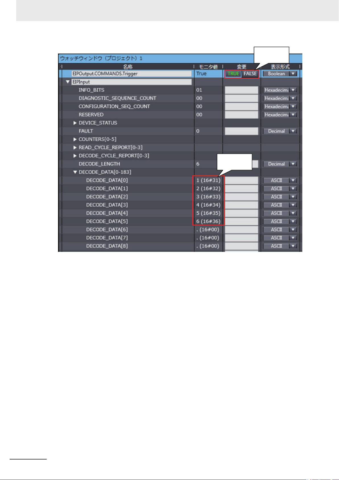
Trigger input
Data output
3 Controlling Operation and Data Output with Ethernet
• Note: When outputting the Code Quality Grade
Read data: 123456 D D A A A D A A
3-20
Autofocus Multicode Reader MicroHAWK V320-F/V330-F/V420-F/V430-F Series User Manual for Communication Settings (Z407-E1)
Page 77

3 Controlling Operation and Data Output with Ethernet
3-1 Controlling Operation and Data Output with Ether-
Net/IP
3
3-1-9 Accessing the NJ-series Controller Communication Areas using Variables
Read 4 Codes and Store the Read String Output on the PLC
<Example of Tag Sets and Connection Settings>
• Input Assembly: 4 Decode Input Assembly (104)
• Output Assembly: Output Assembly (197)
Autofocus Multicode Reader MicroHAWK V320-F/V330-F/V420-F/V430-F Series User Manual for Communication Settings (Z407-E1)
3-21
Page 78

3 Controlling Operation and Data Output with Ethernet
<Example of Setting Variables>
Input Assembly
3-22
Output Assembly
Autofocus Multicode Reader MicroHAWK V320-F/V330-F/V420-F/V430-F Series User Manual for Communication Settings (Z407-E1)
Page 79

3 Controlling Operation and Data Output with Ethernet
3-1 Controlling Operation and Data Output with Ether-
Net/IP
3
<Trigger Input>
<Example of Data Storage>
• Example of PLC data storage for 4 different codes in 1 image capture.
WebLink Screen
3-1-9 Accessing the NJ-series Controller Communication Areas using Variables
PLC
Autofocus Multicode Reader MicroHAWK V320-F/V330-F/V420-F/V430-F Series User Manual for Communication Settings (Z407-E1)
3-23
Page 80

Decoded symbol data
stored in
DECODE_1, 2, 3, 4.
3 Controlling Operation and Data Output with Ethernet
Using the NEW MASTER Bit in the Output Assembly to Register Master
Symbol Data
<Example Tag Sets and Connection Settings>
• Input Assembly: Large Input Assembly (101)
• Output Assembly: Output Assembly (198)
3-24
<Example Variables>
Autofocus Multicode Reader MicroHAWK V320-F/V330-F/V420-F/V430-F Series User Manual for Communication Settings (Z407-E1)
Page 81
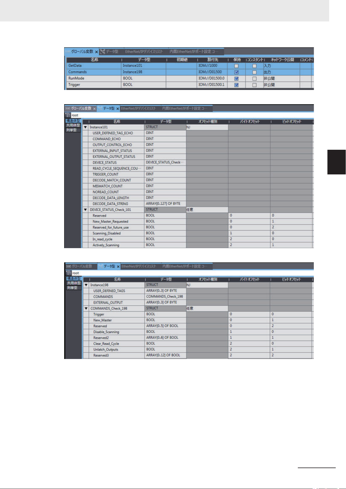
Input Assembly
3 Controlling Operation and Data Output with Ethernet
3-1 Controlling Operation and Data Output with Ether-
Net/IP
3
3-1-9 Accessing the NJ-series Controller Communication Areas using Variables
Output Assembly
Set Matchcode to ON.
• WebLink - Setup Screen
Autofocus Multicode Reader MicroHAWK V320-F/V330-F/V420-F/V430-F Series User Manual for Communication Settings (Z407-E1)
3-25
Page 82

NewMaster bit
set to True.
New_Master_Requested
becomes True and next
Read data is registered
as Master Symbol.
3 Controlling Operation and Data Output with Ethernet
With nothing currently registered as the Master Symbol, when a Read is executed with Matchcode
ON, the result is Mismatch.
By setting the NewMaster bit in the Output Assembly to 1, the next code that is read will be
registered as the Master Symbol data.
<Register the Master Symbol Data>
3-26
<Trigger Input>
Autofocus Multicode Reader MicroHAWK V320-F/V330-F/V420-F/V430-F Series User Manual for Communication Settings (Z407-E1)
Page 83

Trigger bit
set to True.
Becomes False after Read
is executed and
NewMaster is registered.
3 Controlling Operation and Data Output with Ethernet
3-1 Controlling Operation and Data Output with Ether-
Net/IP
3
3-1-9 Accessing the NJ-series Controller Communication Areas using Variables
<Perform a Read to Verify>
Since the data was registered as the Master Symbol, the result is Match.
WebLink Screen
• WebLink - Setup - Matchcode - Match String Editor
Autofocus Multicode Reader MicroHAWK V320-F/V330-F/V420-F/V430-F Series User Manual for Communication Settings (Z407-E1)
3-27
Page 84

Command StringCommand Length
0x08
0x00
0x00
0x00
0x3C('<')
0x4B('K')
0x32('2')
0x32('2')
0x35('5')
0x2C(',')
0x30('0')
0x3E('>')
3 Controlling Operation and Data Output with Ethernet
3-1-10
Communicating with the Code Reader with EtherNet/IP Message
Serial commands can be executed using EtherNet/IP Message (Explicit) communication.
For more information on Serial commands, please refer to the following.
3-2-5 Controlling Operation from an External Device on page 3-39
Note
Any explicit message that causes an action that takes longer than 3 seconds will time out. It is recommended to use implicit messaging in these cases.
Message Communication Objects have the following structure.
Item Setting Value
Class ID 104 (0x68 Hex)
Instance ID 1
Attribute ID 1
Service code 69 (0x45 Hex)
EtherNet/IP Message (Explicit) Format
EtherNet/IP messages, both transmitted and received, are comprised of two parts, the Command
Length and Command String.
• Command Length (4 bytes)
The total number of characters in the Command String.
• Command String (256 byte maximum)
The ASCII character array of the command sent from the PLC to the code reader.
3-28
Autofocus Multicode Reader MicroHAWK V320-F/V330-F/V420-F/V430-F Series User Manual for Communication Settings (Z407-E1)
Page 85

3 Controlling Operation and Data Output with Ethernet
Command Setting Example
This example shows how to set Message communication command strings.
• For the data that is sent from the PLC to the code reader, set a serial command character string.
• When using K Commands some commands do not provide a Response.
However, in the case of a Verify setting command like <K225?>, there is a Response so data will be
received after this command type is sent.
Please note that multiple commands can be sent in a single transmission, so if the command sent
typically doesn’t produce a response a verify setting command can be sent in addition as shown in
Example 3.
Example 1: The received data string when the data was sent using the <K225,0> command.
(Transmitted data) in 12 bytes 0x08 0x00 0x00 0x00 0x3C('<') 0x4B('K') 0x32('2') 0x32('2') 0x35('5')
0x2C(',') 0x30('0') 0x3E('>')
(Received data) None
3-1 Controlling Operation and Data Output with Ether-
Net/IP
3
3-1-10 Communicating with the Code Reader with EtherNet/IP Message
Example 2: The received data string when the data was sent using the <K225?> command.
(Transmitted data) in 11 bytes 0x07 0x00 0x00 0x00 0x3C('<') 0x4B('K') 0x32('2') 0x32('2') 0x35('5')
0x3F('?') 0x3E('>')
(Received data) in 12 bytes 0x08 0x00 0x00 0x00 0x3C('<') 0x4B('K') 0x32('2') 0x32('2') 0x35('5')
0x2C(',') 0x30('0') 0x3E('>')
Example 3: The received data string when the data was sent using the <K225,0><K225?> commands.
(Transmitted data) in 19 bytes 0x0F 0x00 0x00 0x00 0x3C('<') 0x4B('K') 0x32('2') 0x32('2') 0x35('5')
0x2C(',') 0x30('0') 0x3E('>') 0x3C('<') 0x4B('K') 0x32('2') 0x32('2') 0x35('5') 0x3F('?') 0x3E('>')
(Received data) in 12 bytes 0x08 0x00 0x00 0x00 0x3C('<') 0x4B('K') 0x32('2') 0x32('2') 0x35('5')
0x2C(',') 0x30('0') 0x3E('>')
Autofocus Multicode Reader MicroHAWK V320-F/V330-F/V420-F/V430-F Series User Manual for Communication Settings (Z407-E1)
3-29
Page 86

Code ReaderExternal device
Example: Connection request to TCP Port 2001 (Default)
TCP port connection
request
Command
Example: Send Read command "< >" (Default)
Data
Example: Send Read result "ABCDE"
3 Controlling Operation and Data Output with Ethernet
3-2
3-2-1
3-2-2
Controlling Operation and Data Output with Serial (TCP)
This section explains the communications settings required for using Serial (TCP) communications between the code reader and an external device.
Serial (TCP) Overview
Serial (TCP) conforms to the TCP/IP communication protocols. It can be used with any Ethernet communication equipment compatible with TCP/IP communication protocol. Since this code reader communicates as a TCP server, the external device to be connected must be connected to this code reader as a TCP client. If you intend to use with an Omron PLC, please verify that it supports Socket Services (TCP Client).
Communications Processing Flow
In a system configuration in which it is connected by Serial (TCP) communications to an external device (such as PLC), serial commands can be received and code reading results can be output to the
external device.
Below is the basic flow for establishing the Serial (TCP) communications, executing a Read command
and outputting the Read result.
3-30
Autofocus Multicode Reader MicroHAWK V320-F/V330-F/V420-F/V430-F Series User Manual for Communication Settings (Z407-E1)
Page 87

3 Controlling Operation and Data Output with Ethernet
3-2 Controlling Operation and Data Output with Serial
3-2-3
Communication Settings (Serial (TCP))
Network Settings on the Code Reader
Set the IP address on the code reader to match the network settings of the PLC or other external device.
• WebLink - Setup - Gear Icon - Advanced Settings - Communications - Ethernet
1 Set Ethernet to Enabled.
2 Set the IP Address and Subnet mask according to the network settings of the PLC or other
external device.
Setting Item Setting Value Description
Ethernet
• Enabled
(Default)
• Disabled
IP Address a.b.c.d
a: 0 to 255
b: 0 to 255
c: 0 to 255
d: 0 to 255
(Default:
192.168.188.2)
Subnet a.b.c.d
a: 0 to 255
b: 0 to 255
c: 0 to 255
d: 0 to 255
(Default:
255.255.0.0)
Gateway a.b.c.d
a: 0 to 255
b: 0 to 255
c: 0 to 255
d: 0 to 255
(Default: 0.0.0.0)
IP Address Mode
• Fixed
(Default)
• DHCP
TCP Port 1 1024 to 65536
(Default: 2001)
TCP Port 2 1024 to 65536
(Default: 2003)
Select whether to enable all, some, or none of the various
Ethernet protocols, (Serial (TCP)), EtherNet/IP, PROFINET).
Enter the IP address of the Code Reader
Input the subnet mask address.
If a Gateway is used, enter the gateway address. If a Gateway is not used, use the default value 0.0.0.0.
In Fixed mode, the code reader uses a user-defined IP address.
In DHCP mode, the code reader acquires its IP address,
subnet, and gateway from the DHCP server.
Enter one of the two TCP port numbers for communication
with the code reader over Serial (TCP).
Enter one of the two TCP port numbers for communication
with the code reader over Serial (TCP).
(TCP)
3
3-2-3 Communication Settings (Serial (TCP))
Additional Information
Through the use of two TCP ports at the same time, it is possible for this code reader to
communicate over Serial (TCP) with two different external devices.
Autofocus Multicode Reader MicroHAWK V320-F/V330-F/V420-F/V430-F Series User Manual for Communication Settings (Z407-E1)
3-31
Page 88

Character notatiion
Hex notatiion
Serial Trigger
command
<
3C
20>3E
Character notatiion
Hex notatiion
Read result
1
31
2323
33
In Read Cycle
4
34
535CR
0D
LF
0A
Code Reader
External device
3 Controlling Operation and Data Output with Ethernet
Change the Command that Executes Read
It is possible to change the command used in Serial communications to execute Read.
There are two types of Read execution commands. One includes a Separator Character (delimiter) <>
and the other has no delimiter.
• WebLink - Setup - Gear Icon - Advanced Settings - Read Cycle - Serial Trigger (Non-Delimited)
Setting Item Setting Value Description
Serial Trigger Character (Delimited)
Start Character
(Non-Delimited)
Stop Character
(Non-Delimited)
ASCII code for 1
character
(Default: Space
(Hex: 20))
The ASCII codes for
maximum of 2 characters
(Default: NULL
(Hex:00))
The ASCII codes for
maximum of 2 characters
(Default: NULL
(Hex:00))
Specifies the command character string used to start a Read. To
execute the command, the trigger character must be delimited in
brackets <>.
This command can only be executed when the Trigger Mode is
set in Read Cycle - Trigger - Mode to either Serial Data or Serial
Data or External Edge.
Specifies the command character string used to start a Read and
the command character used to end a Read.
The Start command character and the End command character
must be different characters. When set it to NULL (Hex:00) it is
disabled.
The behavior will differ according to the selection made for Read
Cycle - Trigger - Mode.
• If External Edge is selected, the code reader executes Read
with the Start command character. An End command character
is not necessary.
• If External Level or Serial Data and Edge is selected, the Start
trigger character starts a Read cycle and the End command
character ends the Read cycle. Even for a Good Read, the
Read Cycle does not end until the End command is sent.
Example Use of Character (Delimited) Command
• Read string: 12345, Character (Delimited): Space, Preamble: None, Postamble: CRLF
3-32
Autofocus Multicode Reader MicroHAWK V320-F/V330-F/V420-F/V430-F Series User Manual for Communication Settings (Z407-E1)
Page 89

3 Controlling Operation and Data Output with Ethernet
3-2 Controlling Operation and Data Output with Serial
3-2-4
Setting the Data to Output after a Read
The code reader can be configured so that after a Read is executed, its read results are automatically
output to the TCP port it is connected to. Additional information such as print quality grade and code
position coordinates can be appended to the Read result output and the format of that output can be
modified.
Change the Read Result Output Condition
You can change the conditions by which you will output your Read results.
• WebLink - Setup - Gear Icon - Advanced Settings - I/O - Symbol Data Output
Setting Item Setting Value Description
Symbol Data Output
Output Timing
• Disabled
• Match
• Mismatch
• Good Read
(Default)
• Only If All Are
Good Reads
• As Soon As Pos-
sible
(Default)
• End of Read Cy-
cle
• Disabled:
Read result is not output.
• Match:
The Read result is only output when it matches the Master
Symbol set in the Matchcode function.
• Mismatch:
The Read result is only output when it does not match the Master Symbol set in the Matchcode function.
• On Good Read:
Read results are output for even just one Good Read.
• Only If All Are Good Reads:
The Read result is output only when all the symbols specified in
the Read Multiple Symbols function are successfully read.
• As Soon As Possible:
Outputs the Read result immediately on Good Read and ends
the Read Cycle.
• End of Read Cycle:
The Read result is not output until the End of Read Cycle condition is met. The End of Read Cycle condition is set in
Advanced Settings - Read Cycle - End of Read Cycle.
(TCP)
3
3-2-4 Setting the Data to Output after a Read
Set the Data to be Output when There is a No Read.
You can change the data to output when there is a No Read result.
• WebLink - Setup - Gear Icon - Advanced Settings - I/O - No Read Message
Setting Item Setting Value Description
No Read Message
Message NOREAD
Autofocus Multicode Reader MicroHAWK V320-F/V330-F/V420-F/V430-F Series User Manual for Communication Settings (Z407-E1)
• Enabled
(Default)
• Disabled
(Default)
• Enabled:
A message is output when there is a No Read. However, if the
Trigger Mode set in Read Cycle is Continuous Read, no message is output regardless of this setting.
• Disabled:
No message is output for a No Read.
Set the message to output when there is a No Read. You can set
up to 64 ASCII characters.
3-33
Page 90

3 Controlling Operation and Data Output with Ethernet
Header and Footer Settings
You can change the Header (Preamble) and Footer (Postamble) that precedes and follows the Read
string.
• WebLink - Setup - Format Output
1 Set the Header (Preamble) as needed.
In Format Output, check the box for Preamble to add a header to the Read result.
To edit the characters used in the header, click on the blue text to the right of Preamble.
Characters can be entered from the keyboard in to the Text Input Box.
If you want to use a Control Character as the input, select ASCII... below the text input box.
Control characters will be displayed and can be selected from here.
Set the Footer (Postamble) as needed.
2
The procedure for setting it is the same as that for the Header (Preamble).
Additional Information
The Header and Footer can also be set in Advanced Settings - Communications - Preamble /
Postamble.
Setting the Format of Data Output
You can format the Read data you wish to output, for example, by specifying the number of characters
read from a code symbol to output and appending a fixed character string to the output.
• WebLink - Setup - Format Output
3-34
1 Change the format of the output as needed.
Turn Format Output ON.
Autofocus Multicode Reader MicroHAWK V320-F/V330-F/V420-F/V430-F Series User Manual for Communication Settings (Z407-E1)
Page 91

3 Controlling Operation and Data Output with Ethernet
2 The Output Formatting Editor screen opens.
Click on the Format: text in blue below Format Output to open the Output Formatting Editor.
3-2 Controlling Operation and Data Output with Serial
(TCP)
3
3-2-4 Setting the Data to Output after a Read
3 Parse Symbol?Check this box.
Press the appropriate button to select either Extract chars from symbol data, or Insert
your own text.
4 If you want to specify the range (number) of characters from the read character string to output,
select Extract chars from symbol data.
Enter the range for the number of characters to output. In the example setting below, a string
length of 1 to 4 characters is output.
Autofocus Multicode Reader MicroHAWK V320-F/V330-F/V420-F/V430-F Series User Manual for Communication Settings (Z407-E1)
3-35
Page 92

3 Controlling Operation and Data Output with Ethernet
To apply this setting, click the button.
5 If you want to insert a fixed character string in to the read (decoded) character string to output,
select Insert your own text.
The default text in the field is /r. If you click on it, a Text input box will appear so that you can
input text from your keyboard. In the example below, ABC- is set for the 4 characters.
If you want to use a Control Character as the input, select ASCII... below the text input box.
Control characters will be displayed and can be selected from here.
When Input is complete, press Enter on the keyboard.
6 To delete the formatting you set for the output, place the cursor on it and click the X button dis-
played on the upper right.
7 Click the Done button. It will close the Output Formatting Editor screen.
How to Append Additional Symbol Information
3-36
Additional information such as print quality grade and code position coordinates can be appended to
the Read result output.
Outputting a Code Symbol's Position Information
• WebLink - Setup - Gear Icon - Advanced Settings - I/O - Output Object Info
1 Enable Output Coordinates.
Autofocus Multicode Reader MicroHAWK V320-F/V330-F/V420-F/V430-F Series User Manual for Communication Settings (Z407-E1)
Page 93
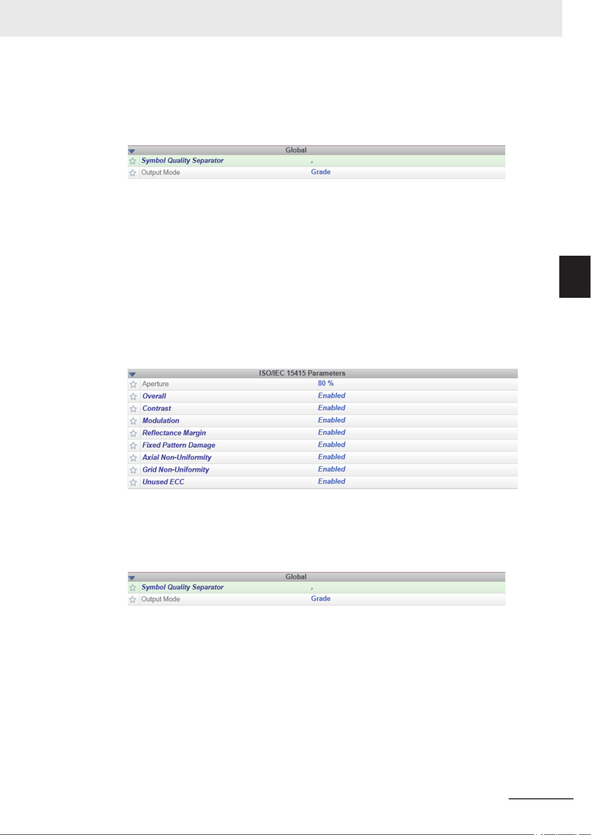
3 Controlling Operation and Data Output with Ethernet
2 If necessary, change the Separator Character.
In WebLink - Setup - Gear Icon - Advanced Settings - Symbol Quality - Global, enter a
character for Symbol Quality Separator. Below is an example where , is used as the Separator Character.
3 The position coordinates of the code symbol is output appended to the Read result.
The following example shows the code symbol's position coordinates appended to the Read
string ABCDE.
ABCDE,(0867,0708)(0867,0708)(1741,0673)(1741,0673)
3-2 Controlling Operation and Data Output with Serial
(TCP)
Output of the Symbol Quality Grade Information (ISO/IEC 15415)
• WebLink - Setup - Gear Icon - Advanced Settings - Symbol Quality - ISO/IEC 15415
1 Enable the Symbol Quality Grade Standard to output
The following is an example where all ISO/IEC 15415 Symbol Quality Grade parameters are
enabled.
2 If necessary, change the Separator Character.
In WebLink - Setup - Gear Icon - Advanced Settings - Symbol Quality - Global, enter a
character for Symbol Quality Separator. Below is an example where , is used as the Separator Character.
3
3-2-4 Setting the Data to Output after a Read
3 The Symbol Quality Grade is output appended to the Read result.
The following example shows Symbol Quality Grades appended to the Read string ABCDE.
ABCDE,C,A,C,C,C,A,A,A
Autofocus Multicode Reader MicroHAWK V320-F/V330-F/V420-F/V430-F Series User Manual for Communication Settings (Z407-E1)
3-37
Page 94

3 Controlling Operation and Data Output with Ethernet
Additional Symbol Information That Can Be Appended
Setting to adjust
Additional
information
Symbol Identifier
Decodes per
Trigger
Configuration
Data Identifier
Frame Number
Code Position Coordinates
Print Quality
(ISO/IEC
16022)
Print Quality
(Omron Microscan)
Print Quality
(ISO/IEC
15415)
Print Quality
(ISO/IEC
15416)
Print Quality
(ISO/IEC
29158)
Read Time I/O - Read
Read CycleIDI/O - Output CycleIDThe Output Cycle ID number (num-
*1. For more information on Symbol Quality Grade, please refer to Autofocus Multicode Reader MicroHAWK
V320-F/V330-F/V420-F/V430-F Series User Manual (Z432-E) – Symbol Quality Grade.
(WebLink -
Advanced
Settings Menu)
I/O - Symbol Data
Output
I/O - Decodes per
Trigger Output
I/O - Database
Identifier Output
I/O - Output Object
Info
I/O - Output Object
Info
Symbol Quality ISO/IEC 16022
Parameters
Symbol Quality Omron Microscan
Parameters
Symbol Quality ISO/IEC 15415
Parameters
Symbol Quality ISO/IEC 15416
Parameters
Symbol Quality ISO/IEC 29158
Parameters
Duration Output
Description
A (3 character) Symbol Identifier indicating the type of the read symbol
is put in front of its Read string.
Outputs the number of Good Read
in Read Cycle.
Outputs the Index Number of the
Configuration Database used to get
a Good Read.
Outputs the Frames number (number of images) that were needed to
get a Good Read result. The output
is a 3 digit number.
Outputs the coordinates of the four
vertices of the read symbol in pixels.
Outputs the DataMatrix Symbol
Quality Grade defined by ISO/IEC
*1
16022.
Outputs the Omron Microscan Pro-
prietary Symbol Quality Grade.
Outputs the Symbol Quality Grade
defined by ISO/IEC 15415 for 2D
*1
Codes.
Outputs the Symbol Quality Grade
defined by ISO/IEC 15416 for Bar-
code symbols.
Outputs the Symbol Quality grade
defined by ISO/IEC TR 29158 for
2D Codes.
Outputs the Read Duration time in
milliseconds.
ber of Reads executed) is output in
hexadecimal format.
*1
*1
*1
Example Output
(For Read string
ABCDE.) The de-
limiter character is
a , <comma>.)
]dlABCDE Put in
ABCDE,00002 1
ABCDE,DB01 2
ABCDE,F010 3
ABCDE,
(0032,0040)
(0287,0056)
(0287,0279)
(0048,0271)
ABCDE,B,A,A,A 5
ABCDE,000,092,14
3,091,001,14.3,200,
16X16,PASS,349
ABCDE,C,A,C,C,C,
A,A,A
ABCDE,C,A,A,A,A,
A,C,A,A,A
ABCDE,C,C,A,B,C,
A,A,A
ABCDE,100 10
ABCDE,CycleID=0x8
Output
Order
front of
the Read
string
4
6
7
8
9
11
3-38
Additional Information
When Multiple Symbol Reading is enabled, the Output Order is read character string of symbol
1, additional information for symbol 1, read character string for symbol 2, additional information
for symbol 2, and so on.
Autofocus Multicode Reader MicroHAWK V320-F/V330-F/V420-F/V430-F Series User Manual for Communication Settings (Z407-E1)
Page 95

Separator
<
K 5
4
1 ,
2
Command
0
0 0
,
3 0
>
Parameter1 Parameter2
Separator
Comma
Comma
3 Controlling Operation and Data Output with Ethernet
3-2 Controlling Operation and Data Output with Serial
3-2-5
Controlling Operation from an External Device
The code reader can be controlled, have its settings viewed and changed from an external device with
the use of serial commands.
The serial commands of this code reader are divided broadly in to two different types.
• Serial Configuration Commands (K Commands)
Commands to change settings on this code reader.
• Serial Utility Commands
Commands used to test Read Rate, get code reader status and control automatic adjustments.
Serial Command Format
Explanation of how commands are formatted in Serial communication.
Common Command Format for Serial Configuration Commands and Serial
Utility Commands
• Enclose the commands in brackets "< >".
• Characters used in commands and data are case-sensitive. Use either upper-case, or lowercase characters as required.
• Serial commands can be linked together in a chain. For example, the following command sets
Trigger Mode to External Trigger/Edge, sets the End of Read Cycle condition to New Trigger, and
saves the setting.
<K200,3> <K220,1> <Z>
(TCP)
3
3-2-5 Controlling Operation from an External Device
Serial Configuration Command (K Commands) Format
• The K Commands consist of the letter K, followed by a three digit number and comma-separated
parameters as shown below.
• Some K Commands can change multiple parameters. For those, if the final parameter does not
need to be changed, it can be omitted.
For example, when using the K Command <K541> which is used for changing both Exposure
time and Gain, if you only need to change the Exposure time, it can be entered as follows.
<K541,1000>
• If the parameter that does not need to be changed is not the last in sequence, only the comma
delimiter for it is necessary.
For example, when using the K Command <K541> which is used for changing both Exposure
time and Gain, if you only need to change the Gain, it can be entered as follows.
<K541,,30>
• If any characters other than numeric values, such as Control characters, need to be used in the
command, they must be entered in hexidecimal format. If you need to include the characters <,>,
comma (,) as parameters, enter them as their hexadecimal value. To enter a hexadecimal value
as a parameter, add lowercase h immediately after the K command.
For example, to set CR (hexadecimal value: 0D) to the footer (postamble), you can enter it as
follows.
Autofocus Multicode Reader MicroHAWK V320-F/V330-F/V420-F/V430-F Series User Manual for Communication Settings (Z407-E1)
3-39
Page 96

<
K 5
4
1 ?
>
- Status Request command
- Response
Header (Preamble)
<
K 5
4
1 ,
2
0
0 0
,
3 0
>
The current settings of the request K command
CR
LF
Footer (Postamble)
<
K 5
4
1 ,
1
- K command (when the Serial Verification function is enabled)
- Response
Header (Preamble)
<
K 5
4
1 ,
1
0
0 0
,
3 0
>
The current settings of the request K command
CR
LF
Footer (Postamble)
0
0 0
>
3 Controlling Operation and Data Output with Ethernet
<K142h,,0D>
• By default, there is no Response when a K Command is used. To query a current state on the
code reader, use a <Knnn?> Command.
For example, the following is the command to query the current Exposure time and Gain settings
and its Response.
Additional Information
The Response includes a Header (Preamble) and Footer (Postamble). The defaults for these
are Header: None and Footer: CRLF (hexadecimal: 0D0A).
• When the Serial Verification function is enabled (by default: disabled), the current setting status
is returned as the response to the K command. If you want to confirm that the K command was
applied correctly, please enable the Serial Verification function.
Additional Information
The Response includes a Header (Preamble) and Footer (Postamble).
Command Format for the Serial Utility
• For the Serial Utility commands, there are commands for which there is a response and com-
3-40
mands for which there is no response. The format of the response differs with each command.
Autofocus Multicode Reader MicroHAWK V320-F/V330-F/V420-F/V430-F Series User Manual for Communication Settings (Z407-E1)
Page 97

<
# a
>
- Application version Request command
- Response
Header (Preamble)
<
# a
/
3 5
-
9
0 0
0
0 9
7
-
1
.
2 .
3
. 3
0
0 8
>
CR
LF
Footer (Postamble)
<
L 1
>
- OUTPUT1 ON Request command
- Response
None
3 Controlling Operation and Data Output with Ethernet
3-2 Controlling Operation and Data Output with Serial
(TCP)
3
3-2-5 Controlling Operation from an External Device
Autofocus Multicode Reader MicroHAWK V320-F/V330-F/V420-F/V430-F Series User Manual for Communication Settings (Z407-E1)
3-41
Page 98

3 Controlling Operation and Data Output with Ethernet
3-2-6
Serial Command List
A list of the supported Serial commands.
Category Command Description
Setting
change (K
Command)
Execute a
Read
Read Test <C> Tests the number of Decodes per second. The
Auto-adjust <@CAL> Automatically adjusts the settings for Expo-
Train <TRAIN> Start the Train operation. Trains with the next
Optimization <OPT> Starts Optimization. Optimization using the
<Knnn, Parameter>
nnn: Threedigit number
of each K
command
User Defined
(Default: < >)
User Defined
(Default: Disabled)
User Defined
(Default: Disabled)
<Cp> Tests the Read Rate (%). The Response data
<J> Ends the Read test. None
<UNTRAIN> Release the Train operation. None
<TRAIN?> Verifies the Train status. Depending on the
Commands to change settings on the code
reader. Refer to the Autofocus Multicode
Reader MicroHAWK V320-F/V330-F/V420-F/
V430-F Series User Manual (Z432-E) Appendices A-6 to A-17 for additional informa-
tion on K Commands.
Command (Delimited) to execute a Read.
(Reference: Change the Command that Exe-
cutes Read on page 3-32)
The Start Character (Non-Delimited)
(Reference: Change the Command that Exe-
cutes Read on page 3-32)
The Stop Character (Non-Delimited)
(Reference: Change the Command that Exe-
cutes Read on page 3-32)
Response data output is the number of Decodes per second and the Read character
string.
output is the percentage of Good Read per
100 Reads and the Read character string.
sure, Focus Position and Symbol Type. Calibration PASSED is output as the Response
data from halfway through the progress and
when calibration completes successfully. If
calibration fails, the message, Calibration
FAILED will be output.
Symbol read. When reading the same code
symbols, using Train can make Reading results more stable.
status of the Train, the Response data will be
one of the following.
• <TRAIN,0>: Default, Train not done
• <TRAIN,1>: Train in progress
• <TRAIN,2>: Training of Symbol complete
next Symbol read. When reading the same
code symbols, using Optimization can make
the Reading speed faster.
<UNOPT> Releases Optimization. None
Response Data Example
(For Read string ABCDE.)
None
(If the Serial Verification function is enabled, the Response
data will be the same as that
for the <Knnn?> command.)
ABCDE
ABCDE
ABCDE
5 Decodes / Sec ABCDE
(By this you can see 5 Good
Read in 1 second)
95% ABCDE
(By this you can see 95 Good
Reads out of 100 Reads.)
Prog | Exposure Gain Brightness 2 | 5764 33 24 100 |
6011 33 37 Calibration
PASSED.
None
<TRAIN,2>
None
*1
*1
*1
3-42
Autofocus Multicode Reader MicroHAWK V320-F/V330-F/V420-F/V430-F Series User Manual for Communication Settings (Z407-E1)
Page 99

3 Controlling Operation and Data Output with Ethernet
3-2 Controlling Operation and Data Output with Serial
Category Command Description
<OPT?> Confirm the Optimization status. Depending
on the Optimization status, the Response data
will be one of the following.
• <OPT,0>: Default, No Optimization
• <OPT,1>: Optimization in Progress
• <OPT,2>: Optimization of Symbol is com-
plete
<?> Gets the hexidecimal number showing the
code reader status. Information for error conditions on the code reader and Read Cycle
status can be obtained. For more detailed information, please refer to Autofocus Multicode
Reader MicroHAWK V320-F/V330-F/V420-F/
V430-F Series User Manual (Z432-E) Appendices A-16 Utilities.
<K?> Queries the settings status of all K Com-
mands.
<K??> Gets the description of all K Command param-
eters.
<K?#> Gets the parameter ranges of all K Com-
mands.
<Knnn?>
(nnn: Threedigit number
of each K
command)
<Knnn??>
(nnn: Threedigit number
of each K
command)
<Knnn?#>
(nnn: Threedigit number
of each K
command)
<Knnn?*>
(nnn: Threedigit number
of each K
command)
Queries the setting status of the specified K
Command.
Queries the parameter description of the
specified K Command.
Gets the parameter range of the specified K
Command.
Gets the same Response data as when the
<Knnn?> command, <Knnn??> command, or
<Knnn?#> command is executed.
Response Data Example
(For Read string ABCDE.)
<OPT,0>
<?/02>
(You can see there is currently
no error condition on the code
reader.)
Settings status of all K Commands.
Description of all K Command
parameters.
Parameter ranges of all K
Commands.
<K541,2000,30>
(Example response to
<K541??> Exposure: 2000us,
Gain: 30)
<K541??,Exposure,Gain>
(Example Response data for
<K541??> You can see that
Parameter 1 is Exposure and
Parameter 2 is Gain.)
<K541?#,Value
25-100000:Def=2500,Value
0-100:Def=33>
(Example Response data for
<K541?#> You can see that
the setting range of Parameter 1 is 25 to 100000 with a
default value of 2500, while
the setting range of Parameter 2 is 0 to 100 with a default
value of 33.)
<K541,2000,30>
<K541??,Exposure,Gain>
<K541?#,Value
25-100000:Def=2500,Value
0-100:Def=33>
(Example Response data for
<K541?*>.)
(TCP)
3
3-2-6 Serial Command List
Autofocus Multicode Reader MicroHAWK V320-F/V330-F/V420-F/V430-F Series User Manual for Communication Settings (Z407-E1)
3-43
Page 100

3 Controlling Operation and Data Output with Ethernet
Category Command Description
Device Control
Counters and
Counter Resets
<L1> Parallel OUTPUT 1 Signal turns ON. None
<L2> Parallel OUTPUT 2 Signal turns ON. None
<L3> Parallel OUTPUT 3 Signal turns ON. None
<l1> Turn ON the target pattern (blue LED). None
<l0> Turn OFF the target pattern (blue LED). None
<I> Disables Read Cycle. While Read Cycle is
Disabled, it cannot accept a trigger.
<H> Enables Read Cycle. None
<q> Gets the number of No Reads in the Read Cy-
cle. The Response data output is q/ followed
by a 9 digit value for the number of No Read.
<q0> Clears the number of No Reads in the Read
Cycle.
<$> Gets the Mismatch Count. The Response data
output is $/ followed by a 9 digit value for the
number of Mismatch.
<$0> Clears the Mismatch Count. None
<N> Gets the number of No Reads. The Response
data output is N/ followed by a 9 digit value for
the number of No Reads
<O> Clears the Mismatch Count. None
<T> Gets the Trigger Input Count. The Response
data output is T/ followed by a 9 digit value for
the number of Triggers.
<U> Clears the Trigger Input Count. None
<V> Gets the Match Count when the Matchcode
function is used. The Response data output is
V/ followed by a 9 digit value for the number of
Matched strings.
<W> Clears the Match Count. None
<X> Gets the Mismatch Count when the Match-
code function is used. The Response data
output is X/ followed by a 9 digit value for the
number of Mismatched strings.
<Y> Clears the Mismatch Count. None
Response Data Example
(For Read string ABCDE.)
None
<q/000000005>
None
<$/000000002>
<N/000000005>
<T/000000010>
<V/000000010>
3-44
Autofocus Multicode Reader MicroHAWK V320-F/V330-F/V420-F/V430-F Series User Manual for Communication Settings (Z407-E1)
 Loading...