

Page 1

USB3 Vision
Aegis Electronic Group, Inc.
For more information please contact Aegis Electronic Group, Inc. *(888)687-6877 *aegis-g2@aegiselect.com *http://www.aegiselect.com
Monochrome / Color CMOS Camera
STC-MBS43U3V (0.4M / Monochrome)
STC-MCS43U3V (0.4M / Color)
STC-MBS163U3V (1.6M / Monochrome)
No.17S010-01
STC-MCS163U3V (1.6M / Color)
Product Specifications and User’s Guide
STC-MBS43U3V / STC-MCS43U3V / STC-MBS163U3V / STC-MCS163U3V
Product Specifications and Use’s Guide
1/68
Page 2

No.17S010-01
Aegis Electronic Group, Inc.
For more information please contact Aegis Electronic Group, Inc. *(888)687-6877 *aegis-g2@aegiselect.com *http://www.aegiselect.com
Table of Contents
1 Product Precautions ............................................................................................ 9
2 Warranty ................................................................................................................ 9
3 Overview ............................................................................................................. 10
3.1 Features ..................................................................................................................................... 10
3.2 Product Number Naming Method ............................................................................................ 10
4 Specifications ...................................................................................................... 11
4.1 Electronic Specifications .......................................................................................................... 11
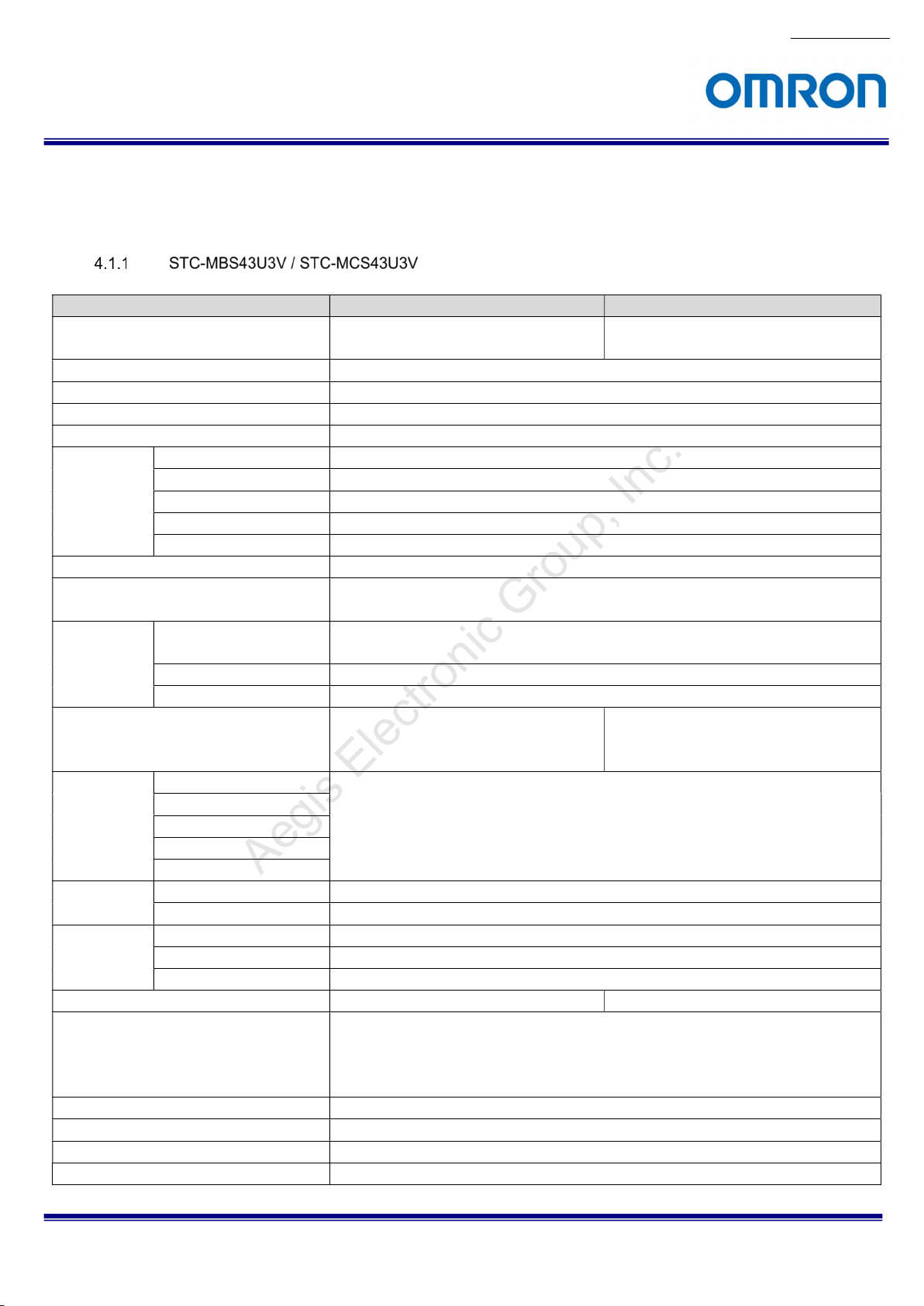
4.1.1 STC-MBS43U3V / STC-MCS43U3V ....................................................................................................... 11
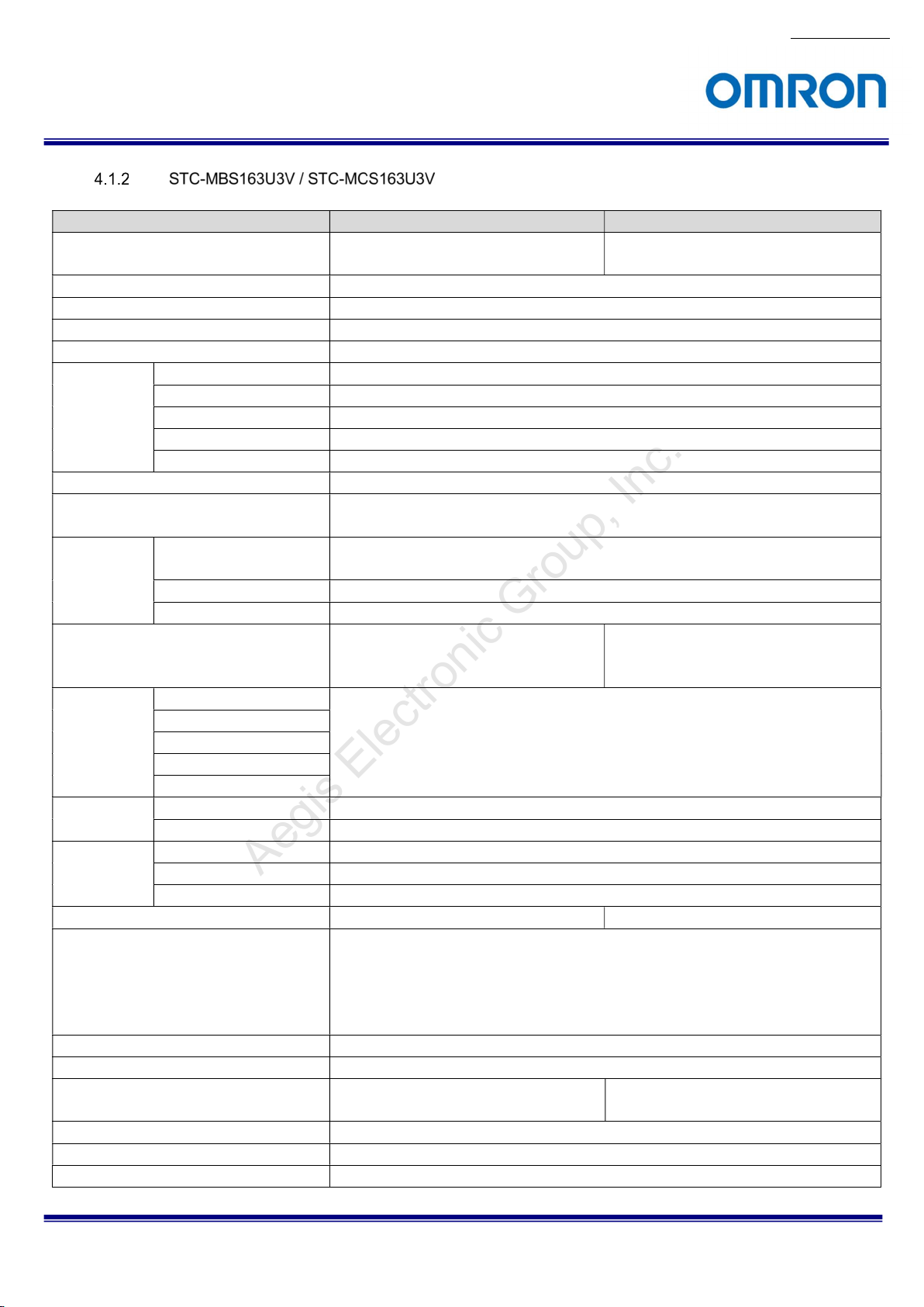
4.1.2 STC-MBS163U3V / STC-MCS163U3V .................................................................................................. 13
4.2 Spectral Sensitivity Characteristics ........................................................................................ 16
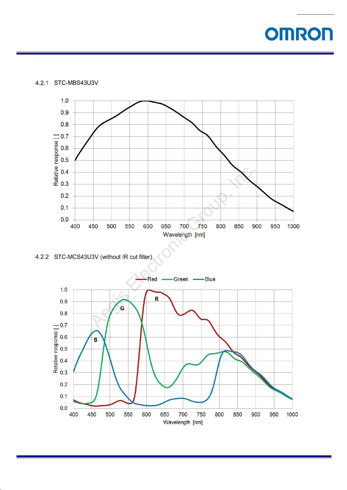
4.2.1 STC-MBS43U3V ................................................................................................................................... 16
4.2.2 STC-MCS43U3V (without IR cut filter) ................................................................................................ 16
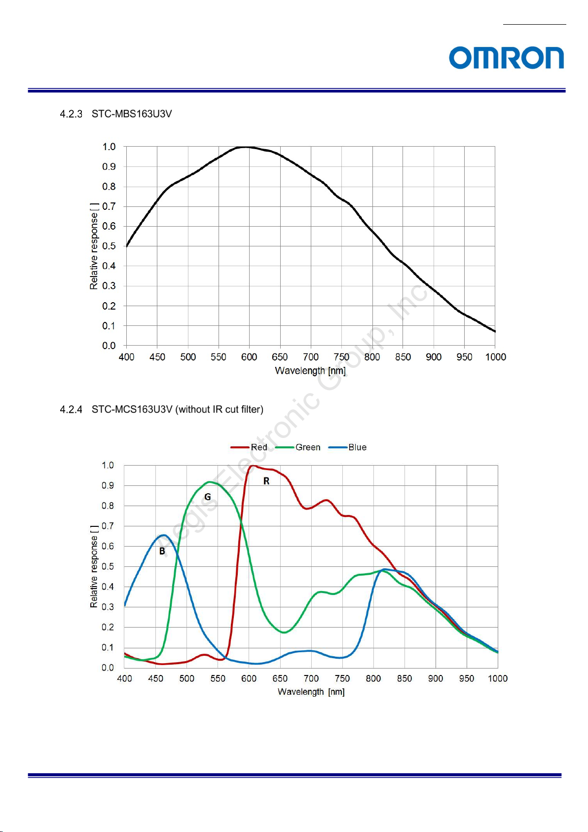
4.2.3 STC-MBS163U3V ................................................................................................................................. 17
4.2.4 STC-MCS163U3V (without IR cut filter) .............................................................................................. 17
4.2.1 IR Cut Filter (STC-MCS43U3V / STC-MCS163U3V) ............................................................................ 18
4.3 Mechanical Specifications ........................................................................................................ 19
4.3.1 STC-MBS43U3V / STC-MCS43U3V ...................................................................................................... 19
4.3.2 STC-MBS163U3V / STC-MCS163U3V .................................................................................................. 19
4.4 Environmental Specifications .................................................................................................. 20
4.4.1 STC-MBS43U3V / STC-MCS43U3V ...................................................................................................... 20
4.4.2 STC-MBS163U3V / STC-MCS163U3V .................................................................................................. 20
4.5 External Connector Specifications .......................................................................................... 21
4.5.1 USB 3.0 micro B ................................................................................................................................... 21
4.5.2 IO Connector ........................................................................................................................................ 22
4.5.3 Reference Input Circuit ....................................................................................................................... 23
4.5.4 Reference Output Circuit .................................................................................................................... 25
5 Dimensions ......................................................................................................... 27
6 Sensor Information ............................................................................................ 28
6.1 Pixel Transferring Image ........................................................................................................... 28
STC-MBS43U3V / STC-MCS43U3V / STC-MBS163U3V / STC-MCS163U3V
Product Specifications and Use’s Guide
2/68
Page 3

No.17S010-01
Aegis Electronic Group, Inc.
For more information please contact Aegis Electronic Group, Inc. *(888)687-6877 *aegis-g2@aegiselect.com *http://www.aegiselect.com
7 Image Acquisition and Camera Operational Modes (GenICam) ...................... 29
7.1 Free run ...................................................................................................................................... 29
7.2 Trigger Mode .............................................................................................................................. 30
7.2.1 Frame Start Trigger (Edge Preset) ...................................................................................................... 31
7.2.2 Frame Start Trigger (Pulse Width Trigger) ......................................................................................... 32
7.2.3 Exposure Start Trigger, Exposure End Trigger .................................................................................. 33
7.2.4 Trigger Software .................................................................................................................................. 33
8 IO Function ......................................................................................................... 34
8.1 Input Port Function ................................................................................................................... 34
8.1.1 Trigger Input ......................................................................................................................................... 34
8.1.2 Line Status ........................................................................................................................................... 34
8.1.3 Line Debouncer .................................................................................................................................... 35
8.1.4 Trigger Delay ........................................................................................................................................ 35
8.2 Output Port Function ................................................................................................................ 36
8.2.1 Line Source .......................................................................................................................................... 36
8.2.2 User Output .......................................................................................................................................... 38
8.2.3 Line Status ........................................................................................................................................... 38
8.2.4 Output signal duration setting and Pulse width setting.................................................................... 38
8.3 Hardware Reset ......................................................................................................................... 38
9 Camera Functions .............................................................................................. 39
9.1 ROI (Region of Interest) ............................................................................................................ 39
9.1.1 ROI (One Region) ................................................................................................................................. 39
9.1.2 Multi ROI (Only available for STC-MBS163U3V / STC-MCS163U3V)................................................. 41
9.2 Pixel Format ............................................................................................................................... 44
9.3 Binning (Only available for STC-MBS163U3V / STC-MCS163U3V) ....................................... 44
9.4 Decimation (Only available for STC-MBS163U3V / STC-MCS163U3V) ................................. 45
9.5 Image Flip .................................................................................................................................. 46
9.6 Priority Mode ............................................................................................................................. 48
9.7 Gain ............................................................................................................................................ 49
9.7.1 Analog Gain ......................................................................................................................................... 49
9.7.2 Digital Gain ........................................................................................................................................... 49
9.7.3 White Balance Gain (Only available for the color model) ................................................................. 49
STC-MBS43U3V / STC-MCS43U3V / STC-MBS163U3V / STC-MCS163U3V
Product Specifications and Use’s Guide
3/68
Page 4

No.17S010-01
Aegis Electronic Group, Inc.
For more information please contact Aegis Electronic Group, Inc. *(888)687-6877 *aegis-g2@aegiselect.com *http://www.aegiselect.com
9.8 Black Level................................................................................................................................. 50
9.9 ALC (Auto Light Control) .......................................................................................................... 50
9.9.1 ALC Control Method ............................................................................................................................ 50
9.9.2 AGC (Auto Gain Control) ..................................................................................................................... 51
9.9.3 Auto Exposure ..................................................................................................................................... 51
9.9.4 The setting procedure of ALC ............................................................................................................. 51
9.10 White Balance (Only available for the color model) ............................................................... 52
9.10.1 White balance control methods .......................................................................................................... 52
9.10.2 Disable .................................................................................................................................................. 52
9.10.3 Manual (Off) .......................................................................................................................................... 52
9.10.4 Auto White Balance (Continuous) ...................................................................................................... 52
9.10.5 Push to Set White Balance (Once) ...................................................................................................... 53
9.11 Gamma Table ............................................................................................................................. 54
9.12 Save and load the camera settings .......................................................................................... 55
9.12.1 Saving the Camera Settings ................................................................................................................ 55
9.12.2 Loading Camera Settings .................................................................................................................... 56
9.12.3 Loading Camera Settings when the Camera Power is on ................................................................. 56
9.12.4 Camera Settings Initialization ............................................................................................................. 56
9.13 Pixel Defect Correction ............................................................................................................. 57
9.14 Trigger ........................................................................................................................................ 57
9.14.1 Trigger Signal Process ........................................................................................................................ 57
9.15 Device User ID ........................................................................................................................... 58
9.16 Event Control (Only available with USB3 Vision protocol) .................................................... 58
9.16.1 The way to use Event .......................................................................................................................... 58
9.16.2 Event Function ..................................................................................................................................... 58
9.17 Chunk Control (Only available with USB3 Vision protocol) .................................................. 59
9.17.1 The way to use Chunk ......................................................................................................................... 59
9.17.2 Chunk Data ........................................................................................................................................... 59
9.18 GenICam command list ............................................................................................................ 60
9.18.1 DeviceControl ...................................................................................................................................... 60
9.18.1 ImageFormatControl............................................................................................................................ 61
9.18.2 AcquisitionControl .............................................................................................................................. 62
9.18.3 TransportLayerControl ........................................................................................................................ 63
9.18.4 DigitalIOControl ................................................................................................................................... 63
9.18.5 CounterAndTimerControl .................................................................................................................... 63
9.18.6 EventControl ........................................................................................................................................ 64
9.18.7 EventExposureEndData ...................................................................................................................... 64
9.18.8 EventExposureStartData ..................................................................................................................... 64
9.18.9 EventTestData ...................................................................................................................................... 64
STC-MBS43U3V / STC-MCS43U3V / STC-MBS163U3V / STC-MCS163U3V
Product Specifications and Use’s Guide
4/68
Page 5

No.17S010-01
Aegis Electronic Group, Inc.
For more information please contact Aegis Electronic Group, Inc. *(888)687-6877 *aegis-g2@aegiselect.com *http://www.aegiselect.com
9.18.10 AnalogControl ................................................................................................................................. 65
9.18.11 LUTControl ...................................................................................................................................... 65
9.18.12 UserSetControl ................................................................................................................................ 65
9.18.13 ChunkDataControl .......................................................................................................................... 66
9.18.14 TestControl ...................................................................................................................................... 66
10 Revision History ................................................................................................. 67
STC-MBS43U3V / STC-MCS43U3V / STC-MBS163U3V / STC-MCS163U3V
Product Specifications and Use’s Guide
5/68
Page 6
No.17S010-01
Aegis Electronic Group, Inc.
For more information please contact Aegis Electronic Group, Inc. *(888)687-6877 *aegis-g2@aegiselect.com *http://www.aegiselect.com
Precautions for safe use
Please read carefully this “Precautions for safe use” before use the camera. Then the camera uses correctly with
agreeing with below notes.
In this “Precautions for safe use”, notes divides into “Warning” and “Caution” to use the camera safety and prevent to
harm and damage.
This shows, assumption for possibility of serious accident leading death or
Warning
Caution
About Graphic
symbols
[Environment / condition]
serious injury if ignore this note and camera uses incorrectly.
This shows, assumption for possibility of bear the damage or physical
damage if ignore this note and camera uses incorrectly.
This symbol shows general prohibition.
This symbol shows completion or instruction.
Warning
Do not use flammable or explosiveness
atmospheres.
This will cause of personal injury or fire.
Do not use for “safety for human body” related
usage.
This camera is designed for use “do not harm
human body immediately” if by any chance the
camera has malfunction.
Caution
Use and store under specified environmental
conditions (Vibration, shock, temperature,
humidity) in the specifications for this camera.
This will cause of fire or damage the camera.
[Installation and cable wiring]
Warning
Do not use with out of power voltage range
that is specified in the specifications for this
camera.
This will cause of fire, electrification or
malfunction.
STC-MBS43U3V / STC-MCS43U3V / STC-MBS163U3V / STC-MCS163U3V
Product Specifications and Use’s Guide
Do not wrong wiring.
This will cause of fire or malfunction.
6/68
Page 7
Aegis Electronic Group, Inc.
For more information please contact Aegis Electronic Group, Inc. *(888)687-6877 *aegis-g2@aegiselect.com *http://www.aegiselect.com
Caution
Do not grounding DC power (+) of all devices
that are connect to the camera.
The camera housing is connecting to 0 V line of
camera inside circuit.
There is a risk of short circuit between camera
inside ciurcuit and frame ground.
This will cause of malfunction.
It is necessary to wiring with turn off the camera.
This will cause of electrification or malfunction.
[Usage instruction]
No.17S010-01
It is necessary to wiring and mounting that is
specified in the specifications for this camera.
This will cause of fire or malfunction.
It is necessary to mounting the camera without
stress for the cable.
This will case of electrification or fire.
Warning
Do not touch the terminal and PCB board
While turn on the camera.
This will cause of electrification or accident
caused by malfunction.
Do not use without usage that is specified in
the specifications for this camera.
This will cause of personal injury or malfunction.
Do not touch the camera housing while or
afterusing the camera.
There is a risk of get burned.
Caution
Do not push contamination into opening of
the camera.
This will cause of electrification or malfunction.
[Maintenance]
Do not put combustibles near the camera.
This will cause of fire.
Do not push metals including screw driver into
radiation holes.
This will cause of electrification or malfunction.
Do not block the radiation holes.
This will cause of fire due to increase the
camera inside temperature.
Caution
Do not disassemble or repair the camera.
This will cause of fire, electrification or
malfunction.
STC-MBS43U3V / STC-MCS43U3V / STC-MBS163U3V / STC-MCS163U3V
Product Specifications and Use’s Guide
It is turn off the camera when maintaining or
inspecting the camera.
This will cause of electrification.
7/68
Page 8
Aegis Electronic Group, Inc.
For more information please contact Aegis Electronic Group, Inc. *(888)687-6877 *aegis-g2@aegiselect.com *http://www.aegiselect.com
[Disposal]
It is necessary to dispose as industrial waste.
]
No.17S010-01
Caution
STC-MBS43U3V / STC-MCS43U3V / STC-MBS163U3V / STC-MCS163U3V
Product Specifications and Use’s Guide
8/68
Page 9

Aegis Electronic Group, Inc.
For more information please contact Aegis Electronic Group, Inc. *(888)687-6877 *aegis-g2@aegiselect.com *http://www.aegiselect.com
1 Product Precautions
Do not give shock to the camera.
Do not haul or damage the camera cable.
Do not wrap the camera with any material while using the camera. This will cause the internal camera
temperature to increase.
When the camera moving or using the place that temperature difference is extreme, countermeasure for
dew condensation (heat removal / cold removal) is necessary.
While the camera is not using, keep the lens cap on the camera to prevent dust or contamination from getting
in the sensor or filter and scratching or damaging it.
Do not keep the camera under the following conditions.
・ In wet, moist, high humidity or dusty place
・ Under direct sunlight
・ In extreme high or low temperature place
・ Near an object that releases a strong magnetic or electric filed
・ Place with strong vibrations
Apply the power that satisfies the specified in specifications for the camera.
The defective pixels may appear due to the sensor characteristics.
Use below recommend materials (or equivalent materials) to clean the surface of glass.
・ Air dust: Non Freon air duster (NAKABAYASHI Co., LTD.)
・ Alcohol: Propan-2-ol (SAN’EI KAKO Co., LTD.)
・ Non-woven: nikowipe clean room (NKB)
Use a soft cloth to clean the camera.
No.17S010-01
2 Warranty
■Warranty period
One year after delivery (However, the camera had malfunction with camera uses correctly)
In below case for a fee even within warranty period.
・The malfunction caused by incorrect usage, incorrect modify or repair.
・The malfunction caused by external shock including the camera dropping after delivery the camera.
・The malfunction caused by fire, earthquake, flood disaster, thunderbolt struck, other natural disaster or
wrong voltage.
■Warranty coverage
Exchange or repair the malfunction camera if the malfunction is occurred by our responsibility.
“Warranty” mean is warranty for the delivered camera itself. Please accept the induction damage by the
camera malfunction is not included.
STC-MBS43U3V / STC-MCS43U3V / STC-MBS163U3V / STC-MCS163U3V
Product Specifications and Use’s Guide
9/68
Page 10
Aegis Electronic Group, Inc.
For more information please contact Aegis Electronic Group, Inc. *(888)687-6877 *aegis-g2@aegiselect.com *http://www.aegiselect.com
3 Overview
This document describes the specification of the following cameras.
STC-MBS43U3V / STC-MCS43U3V
STC-MBS163U3V / STC-MCS163U3V
3.1 Features
・USB3 Vision
・Maximum frame rate (Full resolution): 527.1 fps @ 0.4M 8bits, 238 fps @ 1.6M 8bits
・CMOS (Global Shutter)
・Up to 2,048 Pixel Defect Correction
・8bits, 10bits, 12bits output
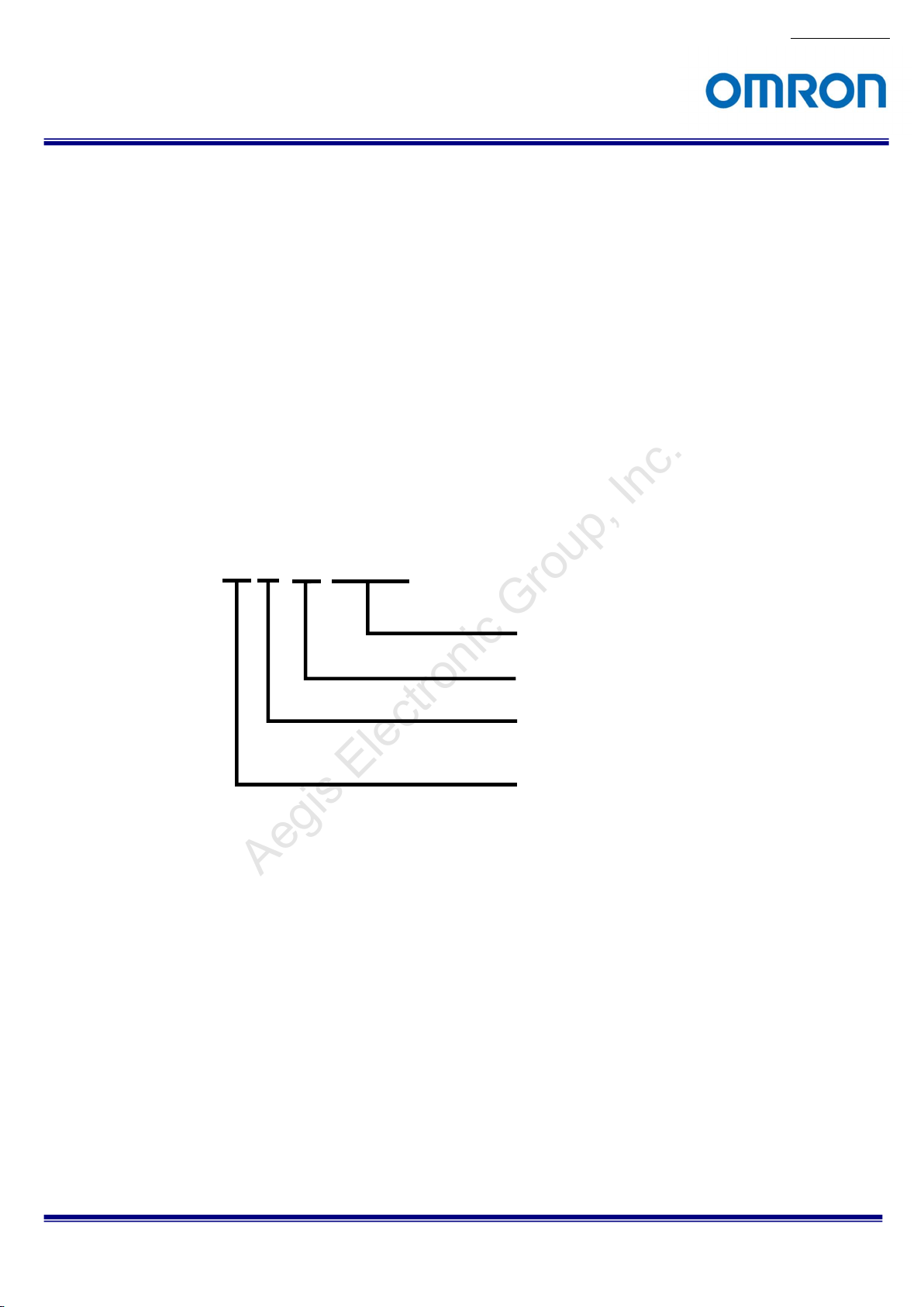
3.2 Product Number Naming Method
No.17S010-01
STC-MxS43U3V
U3V: USB3 Vision
43: 0.4M Pixel, 1/2.9” Sensor
163: 1.6M Pixel, 1/2.9” Sensor
Sensor Manufacturer
S: SONY
B: Monochrome
C: Color
STC-MBS43U3V / STC-MCS43U3V / STC-MBS163U3V / STC-MCS163U3V
Product Specifications and Use’s Guide
10/68
Page 11
Aegis Electronic Group, Inc.
For more information please contact Aegis Electronic Group, Inc. *(888)687-6877 *aegis-g2@aegiselect.com *http://www.aegiselect.com
4 Specifications
4.1 Electronic Specifications
Model Number STC-MBS43U3V STC-MCS43U3V
Image Sensor 1/2.9” 0.4M Progressive Monochrome CMOS
(SONY: IMX287)
Shutter Type Global
Active Picture Elements 720 (H) x 540 (V)
Cell Size 6.9 (H) x 6.9 (V) µm
Sync System
Maximum 8bits output (*1)
Frame Rate 10bits output 439.9 fps
(at Full 10bits Packed output 439.9 fps
scanning) 12bits output 322.1 fps
12bits Packed output 322.1 fps
ADC bit width 10bits / 12bits
Video Format
Noise Level 8bits output Less than 6 digits (Gain 0 dB, Frame rate prioritized) /
10bits / 10bits Packed output
12bits / 12bits Packed output
Sensitivity (*2) 8bits (Frame rate prioritized): 27 Lux
Exposure time 8bits output
10bits output
10bits Packed output
12bits output
12bits Packed output
Gain Analog Gain
Digital Gain
Black Level 8bits output 0 to 31 digits
10bits / 10bits Packed output
12bits / 12bits Packed output
White Balance Gain N/A
ROI
Multi ROIs N/A
Gamma
Binning N/A
Decimation N/A
527.1 fps (Frame rate prioritized mode) / 439.9 fps (Image quality prioritized mode)
8bits (Image quality prioritized) / 10bits /12bits:
Horizontal: 64 to 720 (704 on Packed) pixels / Vertical: 4 to 540 lines (Default: 720 x 540)
16 pixels in horizontal direction (64 pixels on Packed) / 4 lines in vertical direction
Adjustable Steps for offset: 4 pixels in horizontal direction / 4 lines in vertical direction
External trigger (Hardware, Software) / Free run
8bits / 10bits / 12bits output
(Support packed on 10bits / 12bits)
Less than 3 digits (Gain 0 dB, Image quality prioritized)
Less than 12 digits (Gain 0 dB)
Less than 48 digits (Gain 0 dB)
108 Lux
1 µsecond to 16.777 seconds (Default: 1.77373 mseconds)
0 to 19.2 dB (Default: 0 dB)
x1 to x2 (Default: x1)
0 to 127 digits
0 to 511 digits
Adjustable Steps for size:
Gamma Table = 0.1 to 4.0 (Default = 1.0)
Default: Bold
STC-MBS43U3V / STC-MCS43U3V / STC-MBS163U3V / STC-MCS163U3V
Product Specifications and Use’s Guide
1/2.9” 0.4M Progressive Color CMOS
(SONY: IMX287)
8bits (Frame rate prioritized): 60 Lux
8bits (Image quality prioritized) / 10bits /12bits:
240 Lux
0 (Black level) to x3.99 (Default: x1)
No.17S010-01
11/68
Page 12
Aegis Electronic Group, Inc.
For more information please contact Aegis Electronic Group, Inc. *(888)687-6877 *aegis-g2@aegiselect.com *http://www.aegiselect.com
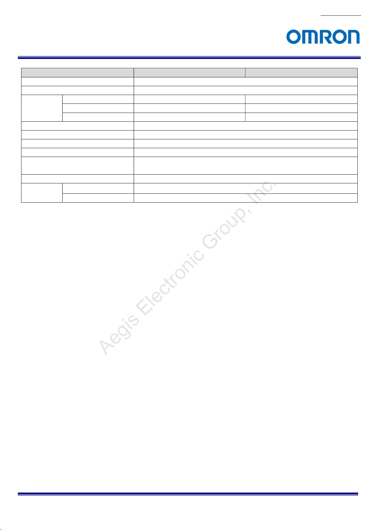
Model Number STC-MBS43U3V STC-MCS43U3V
Image Flip
Defective Pixel Correction Up to 2,048 points
Auto Image
Control
Operational Mode
User Setting Storage Support
Communication Through USB3.0 bus
Interface USB3.0 Super speed (USB3.0 Micro B)
Protocol USB3 Vision® 1.0.1, GenICam Standard Version (SFNC 2.2, PFNC 2.0) compliant
Input / Output Three GPIOs, One Camera Hardware Reset
Power Input Voltage +5V (typ.) (This conforms to USB standard)
Auto Exposure Support Support
Auto Gain Support Support
Auto White Balance N/A Support
Edge preset Trigger / Pulse width Trigger / Start Stop Trigger / Free run
Consumption (*4) Max: 3.4 W, Typ: 3.1 W
Horizontal / Vertical / Horizontal and Vertical / Off
and Sentech’s original protocol (on Standard SDK, Trigger SDK)
Default: Bold
No.17S010-01
STC-MBS43U3V / STC-MCS43U3V / STC-MBS163U3V / STC-MCS163U3V
Product Specifications and Use’s Guide
12/68
Page 13
Aegis Electronic Group, Inc.
For more information please contact Aegis Electronic Group, Inc. *(888)687-6877 *aegis-g2@aegiselect.com *http://www.aegiselect.com
Model Number STC-MBS163U3V STC-MCS163U3V
Image Sensor 1/2.9” 1.6M Progressive Monochrome CMOS
(SONY: IMX273)
Shutter Type Global
Active Picture Elements 1,440 (H) x 1,080 (V)
Cell Size 3.45 (H) x 3.45 (V) µm
Sync System
Maximum 8bits output (*1)
Frame Rate 10bits output 118.1 fps
(at Full 10bits Packed output 183.8 fps
scanning) 12bits output 117.3 fps
12bits Packed output 157.5 fps
ADC bit width 10bits / 12bits
Video Format
Noise Level 8bits output Less than 6 digits (Gain 0 dB, Frame rate prioritized) /
10bits / 10bits Packed output
12bits / 12bits Packed output
Sensitivity (*2) 8bits (Frame rate prioritized): 108 Lux
Exposure time 8bits output
10bits output
10bits Packed output
12bits output
12bits Packed output
Gain Analog Gain
Digital Gain
Black Level 8bits output 0 to 31 digits
10bits / 10bits Packed output
12bits / 12bits Packed output
White Balance Gain N/A
ROI (*3) Horizontal: 64 to 1,440 (1,408 on Packed) pixels / Vertical: 4 to 1,080 lines
Multi ROIs N/A
Gamma
Binning
Decimation
Image Flip
Defective Pixel Correction Up to 2,048 points
238.0 fps (Frame rate prioritized mode) / 200.5 fps (Image quality prioritized mode)
8bits (Image quality prioritized) / 10bits /12bits:
16 pixels in horizontal direction (64 pixels on Packed) / 4 lines in vertical direction
Adjustable Steps for offset: 4 pixels in horizontal direction / 4 lines in vertical direction
Individual x2 Horizontal, Vertical Binning / Off
(Horizontal: Average, Vertical: Addition) (*8)
External trigger (Hardware, Software) / Free run
8bits / 10bits / 12bits output
(Support packed on 10bits / 12bits)
Less than 3 digits (Gain 0 dB, Image quality prioritized)
Less than 12 digits (Gain 0 dB)
Less than 48 digits (Gain 0 dB)
430 Lux
1 µsecond to 16.777 seconds (Default: 4.05736 mseconds)
0 to 19.2 dB (Default: 0 dB)
x1 to x2 (Default: x1)
0 to 127 digits
0 to 511 digits
(Default: 1,440 x 1,080)
Adjustable Steps for image size:
Gamma Table = 0.1 to 4.0 (Default = 1.0)
Individual x2 Horizontal, Vertical Decimation / Off
Horizontal / Vertical / Horizontal and Vertical / Off
1/2.9” 1.6M Progressive Color CMOS
(SONY: IMX273)
8bits (Frame rate prioritized): 240 Lux
8bits (Image quality prioritized) / 10bits /12bits:
960 Lux
0 (Black level) to x3.99 (Default: x1)
N/A
Default: Bold
STC-MBS43U3V / STC-MCS43U3V / STC-MBS163U3V / STC-MCS163U3V
Product Specifications and Use’s Guide
No.17S010-01
13/68
Page 14
Aegis Electronic Group, Inc.
For more information please contact Aegis Electronic Group, Inc. *(888)687-6877 *aegis-g2@aegiselect.com *http://www.aegiselect.com
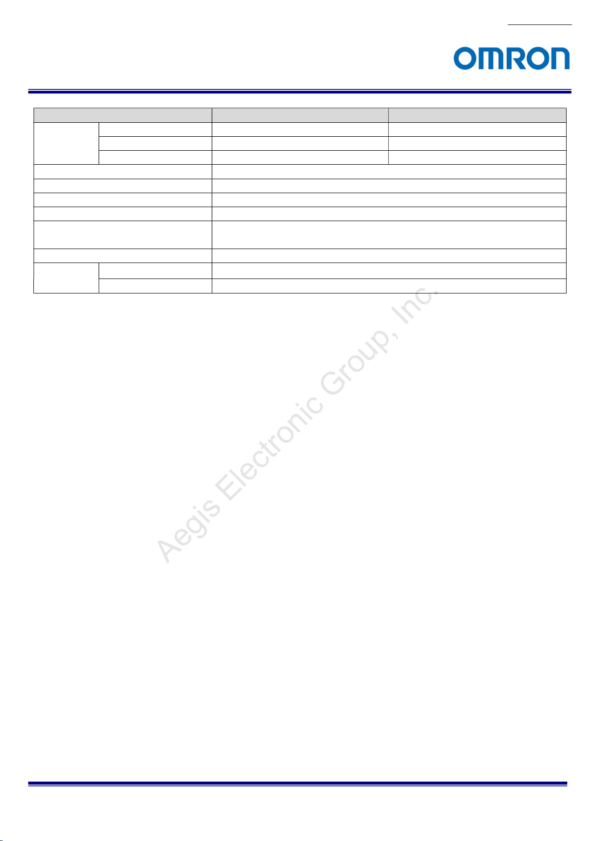
Model Number STC-MBS163U3V STC-MCS163U3V
Auto Image
Control
Operational Mode
User Setting Storage Support
Communication Through USB3.0 bus
Interface USB3.0 Super speed (USB3.0 Micro B)
Protocol USB3 Vision® 1.0.1, GenICam Standard Version (SFNC 2.2, PFNC 2.0) compliant
Input / Output Three GPIOs, One Camera Hardware Reset
Power Input Voltage +5V (typ.) (This conforms to USB standard)
Auto Exposure Support Support
Auto Gain Support Support
Auto White Balance N/A Support
Edge preset Trigger / Pulse width Trigger / Start Stop Trigger / Free run
and Sentech’s original protocol (on Standard SDK, Trigger SDK)
Consumption (*4) Max: 3.8 W, Typ: 3.4 W
Default: Bold
No.17S010-01
STC-MBS43U3V / STC-MCS43U3V / STC-MBS163U3V / STC-MCS163U3V
Product Specifications and Use’s Guide
14/68
Page 15
Aegis Electronic Group, Inc.
For more information please contact Aegis Electronic Group, Inc. *(888)687-6877 *aegis-g2@aegiselect.com *http://www.aegiselect.com
Precautions
(*1) When selecting 8bits output, the priority mode (Image quality / Frame rate) can be selectable.
When selecting “Image quality”, the maximum frame rate is reduced, but the low noise image is acquiring.
When selecting “Frame rate”, the camera can be operated with the fastest frame rate of this camera, but noise
level is greater than “Image quality” selected image.
Please test and select suitable priority mode for the application.
(*2) The sensitivity is measuring the luminance when white level achieved 100 % in below conditions.
Camera Setting Environment
Parameter Setting Parameter Setting
Gain Up 0 dB Light Source Light Box (White)
AGC Off Color temperature 5,100K
White Balance Optimum Lens
Electrical Shutter 1/30 seconds F on Lens F5.6
Black Level Optimum Target Luminance IM-600 (Topcon)
Gamma Factory Setting
(*3) The frame rate does not increase by the binning function.
(*4) The camera operates as USB3.0 standard even the camera connecting to a USB 2.0 port. Please careful
about the power consumption of the camera when the camera connecting to USB2.0 port.
The guideline to perform the full frame rate with full resolution of camera
The data transfer speed on the USB bus is depending on the performance of USB host controller.
The data transfer speed on the USB bus is very important to obtain full frame rate with full resolution. (527.1 fps @
0.4M, 238 fps @ 1.6M)
Renesas / Fresco Logic host controller improved the data transfer speed drastically in the second generation.
However, the transferring speed of Intel chipset is 10 to 20% faster than these host controllers.
When using USB3.0 interface PCI Express board, please insert it to the PCI Express Gen2.0 (5.0[GT/s]) slot. If
non-PCI Express Gen2.0 (5.0[GT/s]) is used, data transfer speed could decrease by about 50%.
If the frame rate is slow due to the performance of USB host controller, the frame rate of camera should adjust
based on the performance of USB host controller. This may resolve to increase the frame rate.
PC resources may have consumed during the image processing (color interpolation, image display, etc.) with huge
image data from camera.
No.17S010-01
STC-MBS43U3V / STC-MCS43U3V / STC-MBS163U3V / STC-MCS163U3V
Product Specifications and Use’s Guide
15/68
Page 16
Aegis Electronic Group, Inc.
For more information please contact Aegis Electronic Group, Inc. *(888)687-6877 *aegis-g2@aegiselect.com *http://www.aegiselect.com
4.2 Spectral Sensitivity Characteristics
No.17S010-01
STC-MBS43U3V / STC-MCS43U3V / STC-MBS163U3V / STC-MCS163U3V
Product Specifications and Use’s Guide
16/68
Page 17
No.17S010-01
Aegis Electronic Group, Inc.
For more information please contact Aegis Electronic Group, Inc. *(888)687-6877 *aegis-g2@aegiselect.com *http://www.aegiselect.com
STC-MBS43U3V / STC-MCS43U3V / STC-MBS163U3V / STC-MCS163U3V
Product Specifications and Use’s Guide
17/68
Page 18

No.17S010-01
Aegis Electronic Group, Inc.
For more information please contact Aegis Electronic Group, Inc. *(888)687-6877 *aegis-g2@aegiselect.com *http://www.aegiselect.com
STC-MBS43U3V / STC-MCS43U3V / STC-MBS163U3V / STC-MCS163U3V
Product Specifications and Use’s Guide
18/68
Page 19
Aegis Electronic Group, Inc.
For more information please contact Aegis Electronic Group, Inc. *(888)687-6877 *aegis-g2@aegiselect.com *http://www.aegiselect.com
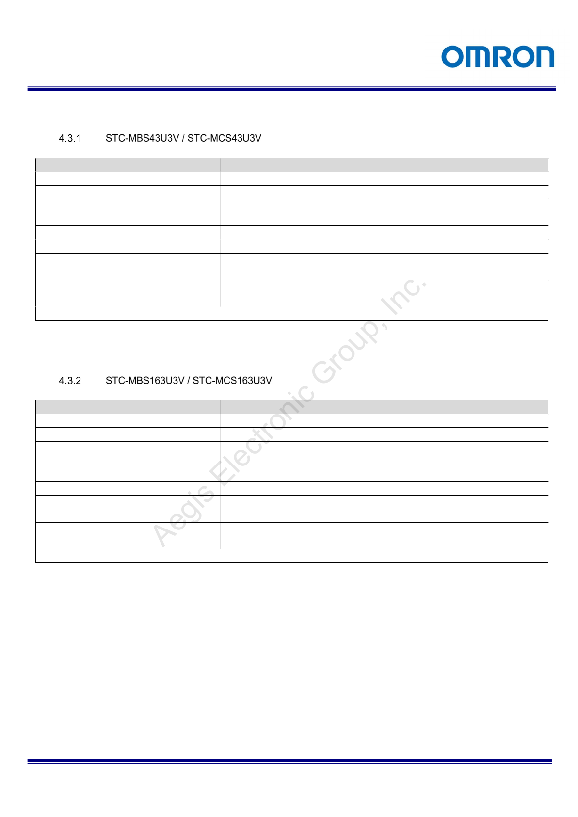
4.3 Mechanical Specifications
Model Number STC-MBS43U3V STC-MCS43U3V
Dimensions 28 (W) x 28 (H) x 40 (D) mm (*1)
Optical Filter No Optical Cut Filter IR Cut Filter
Optical Center Accuracy Positional accuracy in Horizontal and Vertical directions: +/- 0.3 mm
Rotational accuracy of Horizontal and Vertical: +/- 1.5 deg.
Material Aluminum alloy (AC)
Lens Mount (*2) C Mount
Interface Connectors USB Connector: USB3.0 Micro B type
I/O Connector: HR10A-7R-6PB (Hirose) or equivalent
Camera Mounting M2 screw holes (Three on top, bottom and both side plate)
M4 screws holes (Two on top, four on bottom plate)
Weight Approximately 46 g
(*1) Excluding connectors
(*2) Recommend lens: More than F2.8 (Close side)
Model Number STC-MBS163U3V STC-MCS163U3V
Dimensions 28 (W) x 28 (H) x 40 (D) mm (*1)
Optical Filter No Optical Cut Filter IR Cut Filter
Optical Center Accuracy Positional accuracy in Horizontal and Vertical directions: +/- 0.3 mm
Rotational accuracy of Horizontal and Vertical: +/- 1.5 deg.
Material Aluminum alloy (AC)
Lens Mount (*2) C Mount
Interface Connectors USB Connector: USB3.0 Micro B type
I/O Connector: HR10A-7R-6PB (Hirose) or equivalent
Camera Mounting M2 screw holes (Three on top, bottom and both side plate)
M4 screws holes (Two on top, four on bottom plate)
Weight Approximately 46 g
(*1) Excluding connectors
(*2) Recommend lens: More than F2.8 (Close side)
No.17S010-01
STC-MBS43U3V / STC-MCS43U3V / STC-MBS163U3V / STC-MCS163U3V
Product Specifications and Use’s Guide
19/68
Page 20
No.17S010-01
Aegis Electronic Group, Inc.
For more information please contact Aegis Electronic Group, Inc. *(888)687-6877 *aegis-g2@aegiselect.com *http://www.aegiselect.com
4.4 Environmental Specifications
Model Number STC-MBS43U3V STC-MCS43U3V
Operational
Temperature /
Humidity
Storage Temperature / Humidity Environmental Temperature: -25 to +70 deg. C,
Vibration 20 Hz to 200 Hz to 20 Hz (5 min. / cycle), acceleration 10 G, XYZ 3 directions 30 min. each
Shock Acceleration 38 G, half amplitude 6 ms, XYZ 3 directions 3 times each
Standard Compliancy EMS: EN61000-6-2, EMI: EN55011
RoHS RoHS Compliant
Minimum Environmental Temperature: 0 deg. C,
Environmental Humidity: 0 to 85 %RH (No condensation)
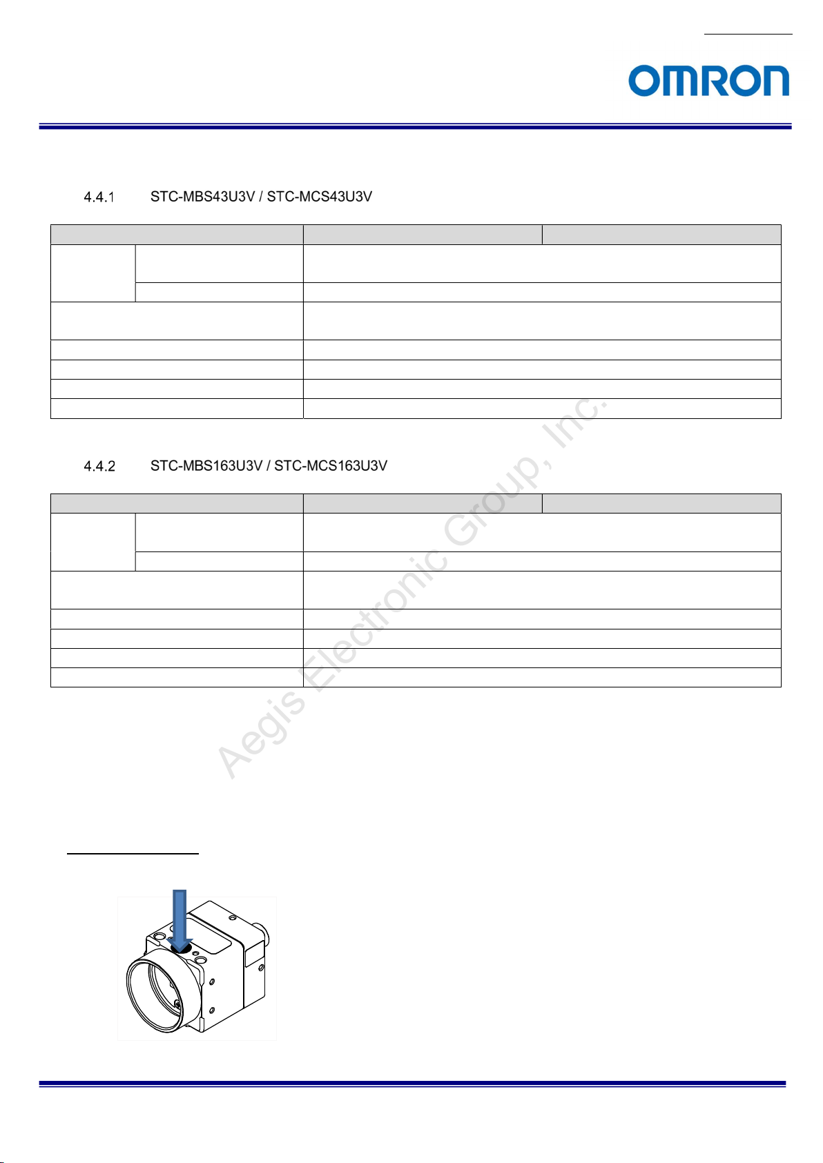
Maximum Camera housing temperature (top plate) shall not exceed 54 deg. C (*1),
Environmental Humidity: 0 to 85 %RH (No condensation)
Model Number STC-MBS163U3V STC-MCS163U3V
Operational
Temperature /
Humidity
Storage Temperature / Humidity Environmental Temperature: -25 to +70 deg. C,
Vibration 20 Hz to 200 Hz to 20 Hz (5 min. / cycle), acceleration 10 G, XYZ 3 directions 30 min. each
Shock Acceleration 38 G, half amplitude 6 ms, XYZ 3 directions 3 times each
Standard Compliancy EMS: EN61000-6-2, EMI: EN55011
RoHS RoHS Compliant
Minimum Environmental Temperature: 0 deg. C,
Environmental Humidity: 0 to 85 %RH (No condensation)
Maximum Camera housing temperature (top plate) shall not exceed 54 deg. C (*1)
Environmental Humidity: 0 to 85 %RH (No condensation)
(*1) Please insure the camera is installed with the appropriate heat dissipation. If camera has a mounted lens and a tripod
with an aluminum plate, this could decrease the camera housing temperature for heat dissipation. When the internal
temperature sensor on the camera shows less than 64 deg. C, the camera housing temperature (top plate) will be less
than 54 deg. C.
Taking these steps will maintain the heat rating of the electronic components of the camera.
Upper side of camera
Measuring point
STC-MBS43U3V / STC-MCS43U3V / STC-MBS163U3V / STC-MCS163U3V
Product Specifications and Use’s Guide
20/68
Page 21
Aegis Electronic Group, Inc.
For more information please contact Aegis Electronic Group, Inc. *(888)687-6877 *aegis-g2@aegiselect.com *http://www.aegiselect.com
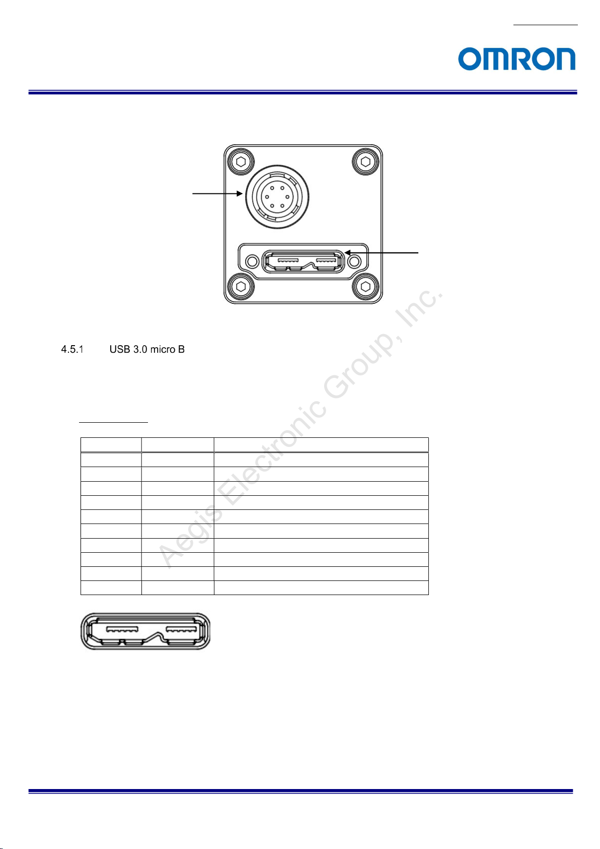
4.5 External Connector Specifications
IO Connector
This connector is compatible with a USB 3.0 micro B connector.
Connector size includes screw lock size and complies with USB3 Vision 1.0.1.
Pin assignment
Pin No. Signal Name
1 VBUS Power
2 D− USB 2.0 differential pair (D−)
3 D+ USB 2.0 differential pair (D+)
4 USB OTG USB OTG ID
5 GND GND
6 SSTX− SuperSpeed transmitter differential pair (−)
7 SSTX+ SuperSpeed transmitter differential pair (+)
8 GND GND
9 SSRX− SuperSpeed receiver differential pair (−)
10 SSRX+ SuperSpeed receiver differential pair (+)
No.17S010-01
USB 3.0 micro B
Connector
Description
12345 678910
STC-MBS43U3V / STC-MCS43U3V / STC-MBS163U3V / STC-MCS163U3V
Product Specifications and Use’s Guide
21/68
Page 22

No.17S010-01
Aegis Electronic Group, Inc.
For more information please contact Aegis Electronic Group, Inc. *(888)687-6877 *aegis-g2@aegiselect.com *http://www.aegiselect.com
HR10A-7R-6PB (Hirose) or equivalent.
This connector is for input and output signals.
Please use HR10A-7P-6S (Hirose) or equivalent connector for cable.
Pin assignment
Pin No. Signal Name
1 GPIO_GND 2 GPIO2 IN/OUT
3 GPIO1 IN/OUT
4 GPIO0 IN/OUT
5 CAM_RESET
6 N.C. -
IN/OUT
IN
* Possible Maximum Rated Voltage is +24 V on CAM_RESET, GPIO0, GPIO1 and GPIO2.
* Please set “OPEN” electrically on N.C. (Pin 6).
Input Output DC characteristics
Signal Name
Pin
No.
1 IO_GND GND - - -
2 GPIO2 General Purpose
3 GPIO1 General Purpose
4 GPIO0 General Purpose
5 CAM_RESET
6 N.C. NC - - - -
Function IN/OUT Voltage Current Reference
Low Voltage High Voltage
Input Output
Input Output
Input Output
Camera
Hardware Reset
IN/OUT IN Less than +1.00 V
OUT 0 to +2.20V (*1) +3.00 to +24 V (*2) 15 mA (Max.) (*3)
IN/OUT IN Less than +1.00 V
OUT 0 to +2.20 V (*1) +3.00 to +24 V (*2) 15 mA (Max.) (*3)
IN/OUT
IN IN Less than +0.80 V
IN Less than +1.00 V
OUT 0 to +2.20 V (*1) +3.00 to +24 V (*2) 15 mA (Max.) (*3)
+3.00 to +24 V 4 µA (typ.) (*4) 2
+3.00 to +24 V 4 µA (typ.) (*4) 2
+3.00 to +24 V 4 µA (typ.) (*4) 2
+3.00 to +24 V 4 µA (typ.)(*4) 1
3,4
3,4
3,4
(*1) The case that output low voltage on 15mA load. The output voltage could be higher voltage due to the generate
voltage by the internal resister when the power consumption is large with low voltage output. Please evaluate
carefully with the actual system.
(*2) The maximum voltage can be applied to connecting IO port as output IO port when external circuits connecting to IO
port. This is equivalent to VCCext on Reference 4.
(*3) When external IO port is connected, control the currency less than 15mA on IO port. Please do not apply more than
15 mA to connecting IO port as output IO port when external circuits connecting to IO port.
(*4) The typical current value when high voltage input into Input port.
STC-MBS43U3V / STC-MCS43U3V / STC-MBS163U3V / STC-MCS163U3V
Product Specifications and Use’s Guide
22/68
Page 23

No.17S010-01
Aegis Electronic Group, Inc.
For more information please contact Aegis Electronic Group, Inc. *(888)687-6877 *aegis-g2@aegiselect.com *http://www.aegiselect.com
Default Setting of Input / Output
Pin No.
2 GPIO2 IN Disable
3 GPIO1 IN Disable
4 GPIO0 IN Disable
CAM_RESET (Reference 1)
Signal
Name
Default
IN/OUT Setting
The camera resets while “CAM_REST pin” connecting to GND 5 seconds in this circuit.
The default camera setting is disable for this reset function. It is necessary to turn ON.
General Purpose Input (Reference 2)
STC-MBS43U3V / STC-MCS43U3V / STC-MBS163U3V / STC-MCS163U3V
Product Specifications and Use’s Guide
23/68
Page 24

No.17S010-01
tIPDHL
Aegis Electronic Group, Inc.
For more information please contact Aegis Electronic Group, Inc. *(888)687-6877 *aegis-g2@aegiselect.com *http://www.aegiselect.com
Input Response Characteristics
The response characteristics of CAM_RESET (Reference1), General Purpose Input (Reference 2) are shown in
the following diagrams
tIPDLH 6.54 µseconds
0.13 µseconds
The capable input trigger’s pulse width is
Positive Trigger: More than tIPDLH
Negative Trigger: More than tIPDHL
USER INPUT
USER_INPUT
Camera internal
カメラ内部
tIPDLH
tIPDHL
90%
10%
Internal Voltage (+3.3V)
入力電圧 High
0V
0V
Internal Voltage
内部電圧
IO_GND
IO_GND
STC-MBS43U3V / STC-MCS43U3V / STC-MBS163U3V / STC-MCS163U3V
Product Specifications and Use’s Guide
24/68
Page 25

No.17S010-01
Aegis Electronic Group, Inc.
For more information please contact Aegis Electronic Group, Inc. *(888)687-6877 *aegis-g2@aegiselect.com *http://www.aegiselect.com
General Purpose Output (Reference 3)
O General Purpose Output (Reference 4)
STC-MBS43U3V / STC-MCS43U3V / STC-MBS163U3V / STC-MCS163U3V
Product Specifications and Use’s Guide
25/68
Page 26

No.17S010-01
Aegis Electronic Group, Inc.
For more information please contact Aegis Electronic Group, Inc. *(888)687-6877 *aegis-g2@aegiselect.com *http://www.aegiselect.com
Output Response Characteristics
The response characteristics of the General Purpose output (Reference 3), and General Purpose output
(Reference 4) are shown in the diagram below. Pulse width is configurable through software.
Please refer to the following response timing table.
VCCext
OPEN (*1) 5 V (*2) 12 V (*2) 24 V (*2)
tOPDHL 0.21 µseconds 0.25 µseconds 0.37 µseconds 0.51 µseconds
tOPDLH 10.40 µseconds 2.69 µseconds 2.68 µseconds 2.61 µseconds
(*1) Measured on +3.3 V internal Voltage at “Reference 4”.
(*2) Measured at “Reference 3”.
Camera internal
カメラ内部
USER_OUTPUT
USER OUTPUT
tOPDHL
tOPDLH
90%
10%
Internal Voltage
内部電圧
0V
0V
+3.3V or VCCext
3.3VまたはVCCext
IO_GND
IO_GND
STC-MBS43U3V / STC-MCS43U3V / STC-MBS163U3V / STC-MCS163U3V
Product Specifications and Use’s Guide
26/68
Page 27

Aegis Electronic Group, Inc.
For more information please contact Aegis Electronic Group, Inc. *(888)687-6877 *aegis-g2@aegiselect.com *http://www.aegiselect.com
5 Dimensions
No.17S010-01
12.5
20
12
28
28
φ 27.6
C mount
9
12
12.5
2-M4 Depth4.0
2414
(46.8)
40
2414
41
24.5
3-M2 Depth2.3
6-M2 Depth2.3
(3-M2 on other side)
4-M4 Depth4.0
4.6
4.8
6.6
2-M2 Depth4.0
18
20
12
14
24
STC-MBS43U3V / STC-MCS43U3V / STC-MBS163U3V / STC-MCS163U3V
Product Specifications and Use’s Guide
13
3-M2 Depth2.3
Unit: mm
27/68
Page 28

Aegis Electronic Group, Inc.
For more information please contact Aegis Electronic Group, Inc. *(888)687-6877 *aegis-g2@aegiselect.com *http://www.aegiselect.com
6 Sensor Information
6.1 Pixel Transferring Image
STC-MBS43U3V / STC-MBS163U3V (Monochrome)
No.17S010-01
Pixel0
of
Data
Pixel1
of
Data
Pixel (n) of Data: nth pixel being transferred
STC-MCS43U3V / STC-MCS163U3V (Color)
Pixel00
of
Data
Pixel01
of
Data
Pixel10
of
Data
Pixel11
of
Data
Pixel (m, n) of Data: nth pixel of the mth line being transferred
STC-MBS43U3V / STC-MCS43U3V / STC-MBS163U3V / STC-MCS163U3V
Product Specifications and Use’s Guide
28/68
Page 29

Aegis Electronic Group, Inc.
For more information please contact Aegis Electronic Group, Inc. *(888)687-6877 *aegis-g2@aegiselect.com *http://www.aegiselect.com
7 Image Acquisition and Camera Operational Modes (GenICam)
Please refer to another chapter for the method of switching Trigger.
GenICam Parameters
TriggerSelector IEnumeration Type Select Trigger function
TriggerMode IEnumeration Type Select ON / OFF which was selected function on TriggerSelector
On: Trigger function ON, Off: Trigger function Off
TriggerSource IEnumeration Type Set Trigger Source which was selected function on TriggerSelector
Software: Trigger control through TriggerSoftware command
LineN: Trigger control through hardware trigger (N: Line number)
ExposureMode IEnumeration Type Select Exposure mode
Please refer to IO function for the (*) Line.
7.1 Free run
Free run mode outputs the camera video image continuously.
In order to run Free run Mode, all trigger functions must be set to OFF via the Trigger mode.
Exposure time determines Exposure Mode. When Exposure Mode is turned off, the frame exposure will complete.
When Exposure Mode is set to Timed, the Exposure Time value will be set as the exposure time.
No.17S010-01
露光
Exposure
VideoOut
映像出力
(*) The camera is set to Free run mode as the default mode.
Exposur eTime
STC-MBS43U3V / STC-MCS43U3V / STC-MBS163U3V / STC-MCS163U3V
Product Specifications and Use’s Guide
29/68
Page 30

Aegis Electronic Group, Inc.
For more information please contact Aegis Electronic Group, Inc. *(888)687-6877 *aegis-g2@aegiselect.com *http://www.aegiselect.com
7.2 Trigger Mode
This trigger consists of Frame Start, Exposure Start and Exposure End.
1) Frame Start
This function has the capability to acquire an image from exposure through the trigger.
The Frame Start function can be enabled when “Frame Start” is selected on Trigger Selector and the Trigger
mode is set to “On”.
This function supports “Edge Preset” trigger and “Pulse Width” trigger with trigger signal. This function can control
exposure through Exposure Mode.
2) Exposure Start, Exposure End
This function has the capability to acquire an image from Exposure Start to Exposure End. Exposure Start trigger
is pair of Exposure End.
Exposure Start and Exposure End are selectable on Trigger Selector. Exposure Start function and Exposure End
function can be enable through each Trigger Mode On.
This function is only enabled when Exposure Mode sets Trigger Controlled. If Exposure Mode did not set Triger
Controlled, camera exposure and image acquisition do not work.
(*) Please do not apply the Trigger through maximum frame rate on Trigger Mode. When Trigger applies within sensor
Readout as exposure end, camera interrupted Readout.
No.17S010-01
STC-MBS43U3V / STC-MCS43U3V / STC-MBS163U3V / STC-MCS163U3V
Product Specifications and Use’s Guide
30/68
Page 31

No.17S010-01
Aegis Electronic Group, Inc.
For more information please contact Aegis Electronic Group, Inc. *(888)687-6877 *aegis-g2@aegiselect.com *http://www.aegiselect.com
The exposure synchronizes trigger signal.
The value on Exposure Time is actual exposure time.
When the polarity on Line Inverter is positive (false), the Exposure starts on the rising edge of trigger.
When the polarity on Line Inverter is negative (true), the Exposure starts on the falling edge of trigger.
To work the camera under this mode, as following setting have to be set.
・Exposure Mode: Timed
・Trigger Selector: Frame Start
・Trigger Mode: On
(*) On Trigger Mode except Frame Start should be set Off.
Timing
トリガー入力(正極性)
トリガー入力(負極性)
露光
映像出力
Trigger Input
(Positive)
Trigger Input
(Negative)
Exposure
VideoOut
Delay time on exposure start timing in the sensor Jitter (unit: μseconds)
Video Output Format
8bits 0 to 13.4 0 to 11.4
10bits
10bits Packed
12bits
12bits Packed
I/O遅延(tIPDL H)
I/O Delay (tIPDLH)
I/O遅延(tIPDH L)
I/O Delay (tIPDHL)
LineDebounceTime
STC-MBS43U3V
STC-MCS43U3V
TriggerDelay
Exposure Start Duration inside of sensor
センサー内部の露光開始遅延
ExposureTime
STC-MBS163U3V
STC-MCS163U3V
STC-MBS43U3V / STC-MCS43U3V / STC-MBS163U3V / STC-MCS163U3V
Product Specifications and Use’s Guide
31/68
Page 32

No.17S010-01
inside of
sensor
Start Duration
inside of
sensor
Aegis Electronic Group, Inc.
For more information please contact Aegis Electronic Group, Inc. *(888)687-6877 *aegis-g2@aegiselect.com *http://www.aegiselect.com
When operating in this mode, the exposure synchronizes the trigger signal.
The exposure time can be controlled by the pulse width of Frame Start trigger.
When the polarity on the Line Inverter is positive (false), the exposure can be controlled at a period of High level
of input trigger signal.
When the polarity on the Line Inverter is negative (true), the exposure can be controlled at a period of Low level
of input trigger signal.
To operate the camera in this mode, the following settings have to be set.
・Exposure Mode: Trigger Width
・Trigger Selector: Frame Start
・Trigger Mode: On
(*) On Trigger Mode except Frame Start should be set Off.
Timing
トリガー入力 (正極性)
トリガー入力 (負極性)
露光
映像出力
Trigger Input
(Positive)
Trigger Input
(Negative)
Exposure
VideoOut
Delay time on exposure start timing in the sensor Jitter (unit: μseconds)
Video Output Format
8bits 0 to 13.4 0 to 11.4
10bits
10bits Packed
12bits
12bits Packed
tPW
I/O Delay (tIPDLH)
I/O遅延(tIPDLH)
tPW
I/O遅延(tIPDHL)
I/O Delay (tIPDHL)
LineDebounceTime
センサー 内部の 露光開 始遅延
Exposure
I/O Delay (tIPDHL)
I/O Delay (tIPDLH)
TriggerDelay
STC-MBS43U3V
STC-MCS43U3V
I/O遅延(tIPDHL)
I/O遅延(tIPDLH)
LineDebounceTime
STC-MBS163U3V
STC-MCS163U3V
TriggerDelay
Exposure Start Duration
センサー 内部の 露光開 始遅延
STC-MBS43U3V / STC-MCS43U3V / STC-MBS163U3V / STC-MCS163U3V
Product Specifications and Use’s Guide
32/68
Page 33

No.17S010-01
Start Duration
inside of
sensor
inside of
sensor
Aegis Electronic Group, Inc.
For more information please contact Aegis Electronic Group, Inc. *(888)687-6877 *aegis-g2@aegiselect.com *http://www.aegiselect.com
Exposure Start trigger determines exposure start timing, Exposure End trigger determines exposure end timing.
To operate the camera under this mode, the following settings have to be set.
・Exposure Mode: Trigger Controlled
・Selects Trigger Selector: Exposure Start, and Trigger Mode: On
・Selects Trigger Selector: Exposure End, and Trigger Mode: On
(*) On Trigger Mode except Frame Start should be set Off.
Timing
ExposureStartトリガー
ExposureStopトリガー
露光
映像出力
Trigger Input
(Positive)
Trigger Input
(Negative)
センサー 内部の 露光開 始遅延
Exposure
Video Out
Exposure
I/O遅延(tI PDLH)
I/O Delay (tIPDLH)
LineDebounceTime
TriggerDelay
I/O遅延(tIPDLH)
I/O Delay (tIPDLH)
LineDebounceTime
(*)When all of Trigger Mode (Frame Start trigger, Exposure Start trigger, Exposure End) are On, camera’s behavior
depends on Exposure Mode setting.
When the Exposure Mode sets the Trigger Control, this function works through Trigger Start/End Trigger
This function works through Frame Start trigger for the remainder of the Exposure Mode.
Delay time on exposure start timing in the sensor Jitter (unit: μseconds)
Video Output Format
STC-MBS43U3V
STC-MCS43U3V
8bits 0 to 13.4 0 to 11.4
10bits
10bits Packed
12bits
12bits Packed
This function can apply either external signal or a software command as the trigger.
The software trigger can be applied through the “execute Trigger Software” command when the trigger is
selected on the Trigger Selector.
STC-MBS43U3V / STC-MCS43U3V / STC-MBS163U3V / STC-MCS163U3V
Product Specifications and Use’s Guide
TriggerDelay
Exposure Start Duration
センサー 内部の 露光開 始遅延
STC-MBS163U3V
STC-MCS163U3V
33/68
Page 34

Aegis Electronic Group, Inc.
For more information please contact Aegis Electronic Group, Inc. *(888)687-6877 *aegis-g2@aegiselect.com *http://www.aegiselect.com
8 IO Function
This chapter describes the IO functions.
In this chapter, the IO Port places as “Line”. The follow chart details the relationship of the Line and IO Port.
IO Port
Pin No.
2 GPIO2 Line2
3 GPIO1 Line1
4 GPIO0 Line0
GenICam Parameters
LineSelector IEnumeration Type
LineMode IEnumeration Type Switch input / output direction for the Line that was selected at LineSelector.
LineInverter IBoolean Type Switch polarity inversion ON / OFF for the Line that was selected at LineSelector.
LineStatus IBoolean Type Line status (High / Low)
LineSource IEnumeration Type Set function for the Line that was selected at LineSelector
UserOutputSelector IEnumeration Type Select UserOutput
UserOutputValue IBoolean Type Switch voltage level of UserOutput that was selected at UserOutputSelector
Select Line
Input: set as input, Output: set as output
False: polarity inversion Off (Active-High),
True: polarity inversion On (Active-Low)
False: Low voltage level, True: High voltage level
8.1 Input Port Function
This function sets the input on Line Mode, then assigns Line as the input.
The following functions can be assigned as input.
When select “input” assign port at the Trigger Source, the input signal can be assigned as Trigger.
The input signal can be switched to Active-Low (Line Inverter: true) or Active-High (Line Inverter: false).
(*) When the Line polarity changing by Line Inverter, the active polarity of input trigger signal is changed.
This function monitors the signal status on the input Line.
The High level (Line Status: true) or Low level (Line Status false) status can be seen through the software.
Signal Name
Line number
No.17S010-01
STC-MBS43U3V / STC-MCS43U3V / STC-MBS163U3V / STC-MCS163U3V
Product Specifications and Use’s Guide
34/68
Page 35

Aegis Electronic Group, Inc.
For more information please contact Aegis Electronic Group, Inc. *(888)687-6877 *aegis-g2@aegiselect.com *http://www.aegiselect.com
Line Debouncer can reduce the wrong input signal detection that is noise on the signal or chartering, by the
filtering input signal.
GenICamParameters
LineDebounceTime Integer Type Line Debounce Time
Range: 0 to 10,000 μseconds, Default: 1 μseconds
Timing
No.17S010-01
Line入力信号
Line Debounce Time
LineDebounceTime
Line Debounce Output
Line Debouncer出力
Line Input
Line
Debounce
Time
As mentioned in the previous chapter, “Image acquisition and Camera Mode”, each trigger can add to the
duration of the input signal
This Trigger Delay can add to the duration per μsecond.
GenICam Parameters
TriggerDelay Integer Type Trigger Delay
Range: 0 to 262,143 μseconds, Default: 0 μsecond
tPW
tPW
STC-MBS43U3V / STC-MCS43U3V / STC-MBS163U3V / STC-MCS163U3V
Product Specifications and Use’s Guide
35/68
Page 36

Aegis Electronic Group, Inc.
For more information please contact Aegis Electronic Group, Inc. *(888)687-6877 *aegis-g2@aegiselect.com *http://www.aegiselect.com
8.2 Output Port Function
This function sets the Output to Line Mode, and then the Line is assigned as the output.
The following functions can be assigned when the IO port is used as the output signal port.
The following list shows the configurable functions available through the Line Source.
The function that describes as “Enable” on “Changeable Polarity” is the configurable polarity on the Line Inverter
(true, false).
No. Function Name Changeable
Polarity
1) Off (Default) -
2) User Output -
3) Trigger Out Enable
4) Exposure End Out Enable
5) Frame End Out Enable
6) Transfer End Out Enable
7) Strobe Out Enable
8) Exposure Active Enable
1) Off (Disable)
Disable the output signal.
2) User Output (General Output)
High or Low level signal that sets on the software is output.
3) Trigger Out (Trigger Output)
The trigger signal that added “Trigger Out Delay (Output pulse delay time)” and “Trigger Out On Time
(Output pulse width)” is output.
4) Exposure End Out (Exposure End)
“Trigger Out on Time (Output pulse width)” activation time signal with set “Trigger Out Delay (Output
pulse delay time)” is output when the expose was finished.
5) Frame End Out (Sensor Readout End)
“Trigger Out on Time (Output pulse width)” activation time signal with set “Trigger Out Delay (Output
pulse delay time)” is output when the sensor read out was finished.
6) Transfer End Out (Transfer End Output)
“Trigger Out on Time (Output pulse width)” activation time signal with set “Trigger Out Delay (Output
pulse delay time)” is output when one frame image transferring from camera was finished.
7) Strobe Out (Strobe Output)
“Strobe Out on Time (Output pulse width)” activation time signal with set “Strobe Out Delay (Strobe
output delay time)” is output when the trigger signal is received.
8) Exposure Active (In Exposure Period)
The signal that activation time is exposure time is output.
(*) Actual exposure period = Output signal pulse width + Minimum exposure time 13.73 μseconds
STC-MBS43U3V / STC-MCS43U3V / STC-MBS163U3V / STC-MCS163U3V
Product Specifications and Use’s Guide
No.17S010-01
36/68
Page 37

No.17S010-01
Aegis Electronic Group, Inc.
For more information please contact Aegis Electronic Group, Inc. *(888)687-6877 *aegis-g2@aegiselect.com *http://www.aegiselect.com
Line Source Timing
トリガー入力
露光
リードア ウト
ReadOut (Sensor to FPGA)
(センサー to FPGA)
映像出力
Trigger Out出力
Strobe Out
Exposure Active
Exposure Active Output
Exposure End Out
Exposure End Out Output
Trigger Input
Exposure
VideoOut
Trigger Out Output
出力
Strobe Out Output
出力
出力
TriggerOutDelay
TriggerOutOnTime
StrobeOutDelay
StrobeOutOnTime
TriggerOutDelay
TriggerOutOnTime
Frame End Out
Frame End Out Output
Transfer End Out
Transfer End Out Output
出力
出力
(*) This timing chart does not include the delay of the IO circuit
(*) The trigger port in this chart describes Frame Start trigger as an example
(*) Trigger Out and Strobe Out do not output from the camera for Exposure Start trigger and Exposure End
trigger
TriggerOutDelay
TriggerOutOnTime
TriggerOutDelay
TriggerOutOnTime
STC-MBS43U3V / STC-MCS43U3V / STC-MBS163U3V / STC-MCS163U3V
Product Specifications and Use’s Guide
37/68
Page 38

Aegis Electronic Group, Inc.
For more information please contact Aegis Electronic Group, Inc. *(888)687-6877 *aegis-g2@aegiselect.com *http://www.aegiselect.com
High or low level signal that was configured on the software is output.
Setting Procedure
Selects Line N (N: any number from 0, 1 or 2)
1) Sets the User Output N (N is Line number) as Line Source
2) Selects User Output N (N is same as selected Line number on User Output) on User Output Selector
3) Sets the value (True: High level, False: Low level) on User Output Value
Monitor the status on output port.
Monitor the output voltage level High (Line Status: true) or Low (Line Status: false) through the software.
Some selectable functions can be modified in order to add to the duration or pulse width on Line Source.
The configurable parameters are shown in the chart below.
Please refer to Line Source for the applicable functions of Parameters.
GenICamParameters
TriggerOutDelay Integer Type Trigger Out Delay Time
Range: 0 to 262,143 μseconds, Default: 0 μsecond
TriggerOutOnTime Integer Type Trigger Out On Time
Range: 4 to 262,143 μseconds, Default: 32 μseconds
StrobeOutDelay Integer Type Strobe Out Delay Time
Range: 0 to 262,143 μseconds, Default: 30 μseconds
StrobeOutOnTime Integer Type Strobe Out On Time
Range: 4 to 262,143 μseconds, Default: 32 μseconds
8.3 Hardware Reset
The hardware reset can be done by CAM_RESET port.
Sets On (Default: Off) at Line Device Reset Mode, and apply the Low voltage in 5 seconds on CAM_RESET port then
camera rest.
No.17S010-01
STC-MBS43U3V / STC-MCS43U3V / STC-MBS163U3V / STC-MCS163U3V
Product Specifications and Use’s Guide
38/68
Page 39

Width
OffsetX
OffsetY
ROI Region
Aegis Electronic Group, Inc.
For more information please contact Aegis Electronic Group, Inc. *(888)687-6877 *aegis-g2@aegiselect.com *http://www.aegiselect.com
9 Camera Functions
This chapter describes the camera functions.
9.1 ROI (Region of Interest)
This sets the ROI in order to output the selected area of image.
The frame rate increases when reducing the height of image. The frame rate does not change when reducing the
width of image.
GenICam Parameters
Width Integer Type Horizontal (Pixel) size
Sets the width of image. “Width + OffsetX” should not exceed the maximum
width.
Height Integer Type Vertical (Line) size
Sets the height of image. “Height + OffsetY” should not exceed the maximum
height.
OffsetX Integer Type Horizontal (Pixel) offset
Default: 0
Setting steps: 4 pixels
OffsetY Integer Type Vertical (Line) offset
Default: 0
Setting steps: 4 lines
The parameters define as following chart.
(*) Width, Height, OffsetX, OffestY setting steps is the same in Binning and Decimation.
No.17S010-01
Height
STC-MBS43U3V / STC-MCS43U3V / STC-MBS163U3V / STC-MCS163U3V
Product Specifications and Use’s Guide
39/68
Page 40

Aegis Electronic Group, Inc.
For more information please contact Aegis Electronic Group, Inc. *(888)687-6877 *aegis-g2@aegiselect.com *http://www.aegiselect.com
Width / Height setting range
STC-MBS43U3V
STC-MCS43U3V
Width Setting range: 64 to 720 pixels
(*) 704 pixels is maximum width on
Packed output
Default: 720 pixels 1,440 pixels
Setting steps 16 pixels unit
(*) 64 pixels unit on Packed output
Height Setting range: 4 to 540 pixels 4 to 1,080 lines
Default: 540 pixels 1,080 lines
Setting steps 4 lines 4 lines
STC-MBS163U3V
STC-MCS163U3V
64 to 1,440 pixels
(*) 1,408 pixels is maximum width on
Packed output
16 pixels unit
(*) 64 pixels unit on Packed output
No.17S010-01
STC-MBS43U3V / STC-MCS43U3V / STC-MBS163U3V / STC-MCS163U3V
Product Specifications and Use’s Guide
40/68
Page 41

No.17S010-01
Aegis Electronic Group, Inc.
For more information please contact Aegis Electronic Group, Inc. *(888)687-6877 *aegis-g2@aegiselect.com *http://www.aegiselect.com
When utilizing the Multi-ROI function, please make note of the following:
This image format is Sentech original format, which does not comply with USB3Vision. Therefore, this Multi ROI
will not work on 3rd party applications that conform to USB3Vision.
To use Multi ROI, one of following application is required.
・The application that built on Sentech’s SDK (Standard SDK / Trigger SDK)
・The application that built on Sentech’s DirectShowFilter
・The application that built on Sentech’s GenTL module (*1)
(*1) Sentech’s original format data process has to be implemented into application
WidthMax
OffsetX[Region0]
OffsetX[Region1]
OffsetY[Re gion0]
Height[Region0]
Region0
Width[Region0] Width[Region1]
OffsetY[Region1]
Height[Region1]
Region1
Multi ROI can be configuring 4 regions as Region 0 to 3.
Region2
HeightMax
Region3
STC-MBS43U3V / STC-MCS43U3V / STC-MBS163U3V / STC-MCS163U3V
Product Specifications and Use’s Guide
41/68
Page 42

Aegis Electronic Group, Inc.
For more information please contact Aegis Electronic Group, Inc. *(888)687-6877 *aegis-g2@aegiselect.com *http://www.aegiselect.com
Restriction of ROI operation
Region 0 is always ON
Region(X+Y) can be enable (On) after sets ON Region (X) and Region (Y).
The following restriction exist to set region’s Width, Height, OffsetX and OffsetY
Width[Region0] = Width[Region1]
Height[Region0] = Height[Region2]
OffsetX[Region0] = OffsetX[Region1]
OffsetY[Region0] = OffsetY[Region2]
Overlapped region setting is invalid
When setting the Horizontal flip, Vertical flip, Horizontal Vertical flip, position of region 0 to 15 are changed.
Please refer to the drawing that follows.
All of selected data outputs as single image data.
If Binning / Decimation is enable, obtained Width and Height values are as “Binning / Decimation” functioned
value. When changing Binning / Decimation settings, the image size and region position are changed.
Please set correct image size and region position after change Binning / Decimation settings.
No.17S010-01
STC-MBS43U3V / STC-MCS43U3V / STC-MBS163U3V / STC-MCS163U3V
Product Specifications and Use’s Guide
42/68
Page 43

No.17S010-01
Aegis Electronic Group, Inc.
For more information please contact Aegis Electronic Group, Inc. *(888)687-6877 *aegis-g2@aegiselect.com *http://www.aegiselect.com
The region position when using image flip function
Region, Width, Height, OffsetX and OffsetY at normal image is applying.
Normal
Region0
Region1
Region2
Region3
Region2
Region3
Region0
Region1
Horizontal flip
Region1
Region0
Vertical flip
Region3
Region2
Region3
Region2
Horizontal and vertical flip
Region1
Region0
STC-MBS43U3V / STC-MCS43U3V / STC-MBS163U3V / STC-MCS163U3V
Product Specifications and Use’s Guide
43/68
Page 44

Aegis Electronic Group, Inc.
For more information please contact Aegis Electronic Group, Inc. *(888)687-6877 *aegis-g2@aegiselect.com *http://www.aegiselect.com
9.2 Pixel Format
The image format from camera can be set on the Pixel Format.
GenICam Parameters
PixelFormat IEnumeration Type Pixel Format
The following chart shows the available Pixel Formats on the camera:
Output Bit Pixel Format
Monochrome Camera Color Camera
8bits Mono8 BayerRG8
10bits Mono10 BayerRG10
10bits Packed Mono10p BayerRG10p
12bits Mono12 BayerRG12
12bits Packed Mono12p BayerRG12p
Each format specified on GenICam PFNC (Pixel Format Naming Convention).
9.3 Binning (Only available for STC-MBS163U3V / STC-MCS163U3V)
Binning is add and average beside pixels into one pixel.
The pixel data inside of red square add or average as one pixel.
Binning
X(Off), Y(Off)
Binning X(Off), Y(On)
Binning X(On), Y(Off) Binning X(On), Y(On)
No.17S010-01
GenICamParameters
BinningHorizontal Integer Type Sets Binning on Horizontal direction
1: Disable Binning 2: Binning 2 Pixel
BinningVertical Integer Type Sets Binning on Vertical direction
1: Disable Binning 2: Binning 2 Pixel
(*) Binning and Decimation function cannot be use simultaneously.
STC-MBS43U3V / STC-MCS43U3V / STC-MBS163U3V / STC-MCS163U3V
Product Specifications and Use’s Guide
44/68
Page 45

Aegis Electronic Group, Inc.
For more information please contact Aegis Electronic Group, Inc. *(888)687-6877 *aegis-g2@aegiselect.com *http://www.aegiselect.com
9.4 Decimation (Only available for STC-MBS163U3V / STC-MCS163U3V)
When using Decimation mode, the decimated image can be output.
The images below show decimated pixels (red squares) where they are output.
Decimation X(Off), Y(Off)
Decimation X(Off), Y(Off)
Decimation X(Off), Y(On)
Decimation X(Off), Y(On)
Decimation X(On), Y(Off) Decimation X(On), Y(On)
Decimation X(On), Y(Off) Decimation X(On), Y(On)
No.17S010-01
GenICam Parameters
DecimationHorizontal Integer Type Sets decimation on horizontal direction
1: Disable Decimation, 2: Decimate one of two pixels
DecimationVertical Integer Type Sets decimation on vertical direction
1: Disable Decimation, 2: Decimate one of two pixels
(*) Binning and Decimation function cannot be use simultaneously.
STC-MBS43U3V / STC-MCS43U3V / STC-MBS163U3V / STC-MCS163U3V
Product Specifications and Use’s Guide
45/68
Page 46

Aegis Electronic Group, Inc.
For more information please contact Aegis Electronic Group, Inc. *(888)687-6877 *aegis-g2@aegiselect.com *http://www.aegiselect.com
9.5 Image Flip
Flip the image through ReverseX and ReverseY.
GenICam Parameters
ReverseX IBoolean Type Switch ON / OFF at Horizontal
False: Horizontal Flip Off, True: Horizontal Flip On. Default: False
ReverseY IBoolean Type Switch ON / OFF at Vertical
False: Vertical Flip Off, True: Vertical Flip On. Default: False
No.17S010-01
Reverse X(Off), Y(Off)
00 01 02 03
10 11 12 13
20 21 22 23
30 31 32 33
Reverse X(On), Y(Off)
Reverse X(Off), Y(On)
30 31 32 33
20 21 22 23
10 11 12 13
00 01 02 03
Reverse X(On), Y(On)
00010203
10111213
20212223
30313233
STC-MBS43U3V / STC-MCS43U3V / STC-MBS163U3V / STC-MCS163U3V
Product Specifications and Use’s Guide
30313233
20212223
10111213
00010203
46/68
Page 47

No.17S010-01
Aegis Electronic Group, Inc.
For more information please contact Aegis Electronic Group, Inc. *(888)687-6877 *aegis-g2@aegiselect.com *http://www.aegiselect.com
Reverse X(Off), Y(Off)
00 01 02 03
10 11 12 13
20 21 22 23
30 31 32 33
Reverse X(On), Y(Off)
Reverse X(Off), Y(On)
30 31 32 33
20 21 22 23
10 11 12 13
00 01 02 03
Reverse X(On), Y(On)
00010203
10111213
20212223
(*) When the image is flipping for color camera, the pixel array is also flipped.
30313233
30313233
20212223
10111213
00010203
STC-MBS43U3V / STC-MCS43U3V / STC-MBS163U3V / STC-MCS163U3V
Product Specifications and Use’s Guide
47/68
Page 48

No.17S010-01
Aegis Electronic Group, Inc.
For more information please contact Aegis Electronic Group, Inc. *(888)687-6877 *aegis-g2@aegiselect.com *http://www.aegiselect.com
9.6 Priority Mode
The frame rate prioritized mode or the Image quality prioritized mode is selectable for 8bits image output.
GenICam Parameters
PrioiryMode IEnumeration 型 Switch Priority mode for 8bits output
0: Image quality prioritized, 1: Frame rate prioritized,
Default: Image quality prioritized
STC-MBS43U3V / STC-MCS43U3V
Priority Mode Maximum frame rate (fps)
Image quality 439.9 Less than 3 digits (Gain 0 dB)
Frame rate 527.1 Less than 6 digits (Gain 0 dB)
Noise level
STC-MBS163U3V / STC-MCS163U3V
Priority Mode Maximum frame rate (fps)
Image quality 200.5 Less than 3 digits (Gain 0 dB)
Frame rate 238.0 Less than 6 digits (Gain 0 dB)
Noise level
STC-MBS43U3V / STC-MCS43U3V / STC-MBS163U3V / STC-MCS163U3V
Product Specifications and Use’s Guide
48/68
Page 49

Aegis Electronic Group, Inc.
For more information please contact Aegis Electronic Group, Inc. *(888)687-6877 *aegis-g2@aegiselect.com *http://www.aegiselect.com
9.7 Gain
The gain has Analog Gain, Digital Gain and White Balance Gain.
(*) When increasing the gain level may increase the noise level.
Please check the image on the actual environment when adjusting brightness of image.
This parameter sets the analog gain.
Selects “Analog ALL” at “Gain Selector”, sets gain at “Gain[Gain Selector]”.
GenICam Parameters
Gain[Analog All] IFloat Type Analog Gain
Range: 0 to 192, Default: 0
Analog Gain Formula
Gain (dB) = Gain[Analog All] / 10
This parameter sets the digital gain.
Selects “Digital ALL” at “Gain Selector”, sets gain at “Gain[Gain Selector]”.
GenICam Parameters
Gain[Digital All] IFloat Type Digital Gain
Range: 0 to 64, Default: 0
Digital Gain Formula
Gain (x times) = 1 + (Gain[Digital All] / 64)
This parameter sets the Bayer patter color gain.
Sets gain at “Balance Ratio” for selected color at “Balance Ratio Selector”.
GenICam Parameters
BalanceRatio[BalanceRatioSelector] IFloat Type White Balance Gain
Range: 0 to 511,
Default: Red: 158, Green: 128, Blue: 304
White Balance Gain Formula
Gain (x times) = BalanceRatio[BalanceRatioSelector] / 128
No.17S010-01
STC-MBS43U3V / STC-MCS43U3V / STC-MBS163U3V / STC-MCS163U3V
Product Specifications and Use’s Guide
49/68
Page 50

Aegis Electronic Group, Inc.
For more information please contact Aegis Electronic Group, Inc. *(888)687-6877 *aegis-g2@aegiselect.com *http://www.aegiselect.com
9.8 Black Level
This parameter sets the black level (the clamp level for the black signal).
Sets the black level at “BlackLevel[Black Level Selector]”.
The lower limit of the signal is clamped at this setting level. The signal does not lower than this.
(*) “Analog All” is only selectable at “Black Level Selector”.
GenICam Parameters
BlackLevel[Black Level Selector] IFloat Type Black Level, Default: 7 (on 8bits output)
Range:
8bits output: 0 to 31
10bits output: 0 to 127 (10bits Packed outputs same as this mode)
12bits output: 0 to 511 (12bits Packed outputs same as this mode)
9.9 ALC (Auto Light Control)
ALC has AGC (Auto Gain Control) and auto exposure function. It can be set individually.
The camera parameters adjust automatically based on current brightness of image, to achieve the target brightness
with ALC function.
GenICam Parameters (for AGC and Auto Exposure)
AutoLightTarget Integer Type Target Brightness
Range: 0 to 255, Default: 127
Target Brightness Formula (Auto Light Target)
8bits output: Target Brightness (Gradient) = Auto Light Target
10bits output: Target Brightness (Gradient) = Auto Light Target × 4
12bits output: Target Brightness (Gradient) = Auto Light Target × 16
The brightness of image adjusts to achieve “Auto Light Target” brightness with AGC and auto exposure function.
When AGC and auto exposure are enabled, at first, the brightness adjusts with auto exposure function. If the
brightness does not achieve “Auto Light Target” brightness with auto exposure function, the brightness adjusts
with the AGC function.
No.17S010-01
STC-MBS43U3V / STC-MCS43U3V / STC-MBS163U3V / STC-MCS163U3V
Product Specifications and Use’s Guide
50/68
Page 51

Aegis Electronic Group, Inc.
For more information please contact Aegis Electronic Group, Inc. *(888)687-6877 *aegis-g2@aegiselect.com *http://www.aegiselect.com
The gain adjusts automatically to achieve the target brightness.
When the current brightness of image was darker than target brightness, increases the gain up to “Gain Auto
Limit Max”.
When the current brightness of image was brighter than target brightness, decrease the gain down to “Gain Auto
Limit Min”.
GenICam Parameters
GainAuto IEnumeration Type Switch ON / OFF for AGC
Continuous: AGC On, Off: AGC Off.
Default: Off
GainAutoLimitMax IFloat Type Sets the maximum gain for AGC
Range: 0 to 192, Default: 127
This value sets as maximum gain for AGC.
GainAutoLimitMin IFloat Type Sets the minimum gain for AGC
Range: 0 to 192, Default: 0
This value sets as minimum gain for AGC.
The exposure time adjusts automatically to achieve the target brightness.
When the current brightness of image was darker than target brightness, extend exposure time up to “Exposure
Auto Limit Max”.
When the current brightness of image was darker than target brightness, reduce exposure time down to
“Exposure Auto Limit Min”.
GenICamParameters
ExposureAuto IEnumeration Type Switch ON / OFF for Auto Exposure
Continuous: Auto Exposure On,
Off: Auto Exposure Off.
Default: Off
ExposureAutoLimitMax IFloat Type Sets the maximum exposure time in μsecond unit
Range: Same as Exposure Time Range for each PixelFormat
ExposureAutoLimitMin IFloat Type Sets the minimum exposure time in μsecond unit
Range: Same as Exposure Time Range for each PixelFormat
Please follow setting procedure shown below.
Setting Procedure
1. Sets “Timed” at “Exposure Mode” (When using Auto Exposure)
2. Sets “Continuous” at “Exposure Auto” (When using Auto Exposure)
3. Sets “Exposure Auto Limit Max” (When using Auto Exposure)
4. Sets “Exposure Auto Limit Min” (When using Auto Exposure)
5. Sets “Continuous” at “Gain Auto” (When using AGC)
6. Sets “Gain Auto Limit Max” (When using AGC)
7. Sets “Gain Auto Limit Min” (When using AGC)
STC-MBS43U3V / STC-MCS43U3V / STC-MBS163U3V / STC-MCS163U3V
Product Specifications and Use’s Guide
No.17S010-01
51/68
Page 52

Aegis Electronic Group, Inc.
For more information please contact Aegis Electronic Group, Inc. *(888)687-6877 *aegis-g2@aegiselect.com *http://www.aegiselect.com
9.10 White Balance (Only available for the color model)
The color compensates by the gain adjustment for each individual color.
The gain for each color has to adjust to same brightness with the flat white target.
The white balance control methods are the listed in the below:
・Disable
・Manual (Off)
・Auto White Balance (Continuous)
・Push to set white balance (Once)
GenICam Parameters
BalanceWhiteAuto IEnumeration Type White balance control method selection.
Default: Off (Manual)
BalanceRatioSelector IEnumeration Type White balance control target color selection.
BalanceRatio IFloat Type Color gain setting for selected color selects at “BalanceRatioSelector”.
Disabled white balance gain and each color gain set as x1.
Setting Procedure
1. Sets “Disable” at “Balance White Auto”
The optimized Balance Ratio (Red, Green or Blue) for the white balance.
Setting Procedure
1. Sets “Red” (when Red gain set) at “Balance White Selector”
2. Sets value at “Balance Ratio”
3. Sets “Green” at “Balance White Selector”
4. Sets value at “Balance Ratio”
5. Sets “Blue” (when Blue gain set) at “Balance White Selector”
6. Sets value at “Balance Ratio”
7. Sets “Off” at “Balance White Auto”
Optimizes white balance gain each frame automatically.
Setting Procedure
1. Sets “Continuous” at “Balance White Auto”
No.17S010-01
STC-MBS43U3V / STC-MCS43U3V / STC-MBS163U3V / STC-MCS163U3V
Product Specifications and Use’s Guide
52/68
Page 53

Aegis Electronic Group, Inc.
For more information please contact Aegis Electronic Group, Inc. *(888)687-6877 *aegis-g2@aegiselect.com *http://www.aegiselect.com
The white balance gain adjusts once after selecting this white balance method. Then each gain set to “Balance
White (Red, Green and Blue)”.
Sets “Off” at “Balance White Auto” automatically after set “White Balance Gain”.
Setting Procedure
1. Sets the flat white target (To process white balance correctly)
2. Sets Once on Balance White Auto
No.17S010-01
STC-MBS43U3V / STC-MCS43U3V / STC-MBS163U3V / STC-MCS163U3V
Product Specifications and Use’s Guide
53/68
Page 54

Aegis Electronic Group, Inc.
For more information please contact Aegis Electronic Group, Inc. *(888)687-6877 *aegis-g2@aegiselect.com *http://www.aegiselect.com
9.11 Gamma Table
The linearity of gradient of image can be correct by the gamma table on the camera.
GenICam Parameters
Gamma IFloat Type Gamma
Gamma Formula
For 12bits image
入力データ
Output data = 4,095 x
For 10bits image
Output data = 1,023 x
For 8bits image
Output data = 255 x
The input signal divides into 32 equal part and have 33 points of gamma table.
The between the points is generates by the linear interpolation.
For 12bits image (Gamma = 2.0)
4096
3584
4096
1024
256
・出力データ
・出力データ
・出力データ
Input data
4096
入力データ
Input data
1024
入力データ
Input data
256
4,095
1,023
Range: 0.1 to 4.0, Default: 1.0
γ
γ
γ
γ
γ
γ
255
No.17S010-01
B point
A point
3072
2560
2048
Output data
1536
1024
512
0
0 512 1024 1536 2048 2560 3072 3584 4096
STC-MBS43U3V / STC-MCS43U3V / STC-MBS163U3V / STC-MCS163U3V
Product Specifications and Use’s Guide
Gamma Table
Generate by the linear
interpolation with A point
and B point.
Input data
54/68
Page 55

Selector
Aegis Electronic Group, Inc.
For more information please contact Aegis Electronic Group, Inc. *(888)687-6877 *aegis-g2@aegiselect.com *http://www.aegiselect.com
9.12 Save and load the camera settings
The camera has the camera setting save function, the camera setting including factory default loads function.
The camera has below two camera settings.
Default: The factory default settings (This setting cannot change)
User Set X: Over writeable camera settings (X: 0 to 7)
These camera settings load from ROM to the register in the RAM on the camera and camera settings save to ROM.
The camera settings saving and loading is controllable with Parameters (User Set Selector, User Set Default), and
commands (UserSetLoad, UserSetSave) in UserSetControl category of GenICam.
The details of the parameters and the functions are in the table below:
GenICam Parameters
UserSetSelector IEnumeration Type Select “Default” or ”UserSet1”
UserSetLoad or UserSetSave process for the selected settings.
UserSetLoad ICommand Type The camera settings load from ROM to the register in RAM.
UserSetSave ICommand Type The camera settings at the register in RAM save to ROM.
UserSetDefault IEnumeration Type Select which settings (“Default or UserSet X) load automatically when the
camera power is on. This selection saves automatically.
Camera
Setting
UserSetSelector
Setting Procedure
1. Selects “UserSetX” at “UserSetSelector”
2. Execute “UserSetSave”
ROM
UserSetX
ROM
Default
When UserSetSave is executing,
the camera settings at the register in RAM
are saved to the ROM that is selected at
UserSetSelector.
Caution:
UserSetSave cannot execute when “Default”
was selected at “UserSet Selector”
No.17S010-01
STC-MBS43U3V / STC-MCS43U3V / STC-MBS163U3V / STC-MCS163U3V
Product Specifications and Use’s Guide
55/68
Page 56

Selector
Selector
Aegis Electronic Group, Inc.
For more information please contact Aegis Electronic Group, Inc. *(888)687-6877 *aegis-g2@aegiselect.com *http://www.aegiselect.com
ROM
UserSetX
ROM
Default
UserSetSelector
Setting Procedure
1. Select “UserSetX” (or Default) at “UserSetSelector”
2. Execute “UserSetLoad”
ROM
UserSetX
ROM
Default
UserSetSelector
Setting Procedure
1. Set “UserSetX” or “Default” at “UserSetDefault”
Please follow the below procedure for the camera settings put back to the factory default settings.
Setting Procedure
1. Selects “Default” at “UserSetSelector”.
2. Executes “UserSetLoad”.
Camera
Setting
Camera
Setting
No.17S010-01
When UserSetLoad is executing,
the camera settings load from the selected
ROM that was selected at “UserSetSelector”
to the register at RAM.
When the camera power is on,
the camera settings load from the selected
ROM that was selected at “UserSetDefault”
to the register at RAM.
STC-MBS43U3V / STC-MCS43U3V / STC-MBS163U3V / STC-MCS163U3V
Product Specifications and Use’s Guide
56/68
Page 57

Aegis Electronic Group, Inc.
For more information please contact Aegis Electronic Group, Inc. *(888)687-6877 *aegis-g2@aegiselect.com *http://www.aegiselect.com
9.13 Pixel Defect Correction
The defected pixel corrects with horizontally beside pixel information.
In the color camera, using same color of horizontally beside same pixel.
When consecutive defect pixels are selected, corrects up to 2 pixels.
GenICamParameters
PixelCorrectionAllEnabled IBoolean Type Switch ON / OFF for Pixel Defect Correction
True: On, False: Off
PixelCorrectionIndex Integer Type Pixel Correction Index
PixelCorrectionX Integer Type Defect position on X coordinate for Index was selected at
“PixelCorrectionIndex”
PixelCorrectionY Integer Type Defect position on Y coordinate for Index was selected at
“PixelCorrectionIndex”
PixellCorrectionEnabled IBoolean Type Switch ON / OFF for pixel defect correction for Index was selected at
“PixelCorrectionIndex”
True: On, False: Off
9.14 Trigger
The description of trigger type and characteristic, please refer to the chapter “Image acquisition and Camera Mode”.
When the external hardware or software signal is input to the camera, the following process are proceeding.
No.17S010-01
Line0
Line1
Line2
Software Trigger
Trigger Source
Line
Debouncer
Trigger
Selector
Trigger
Delay
トリガー
Trigger
STC-MBS43U3V / STC-MCS43U3V / STC-MBS163U3V / STC-MCS163U3V
Product Specifications and Use’s Guide
57/68
Page 58

9.15 Device User ID
Aegis Electronic Group, Inc.
For more information please contact Aegis Electronic Group, Inc. *(888)687-6877 *aegis-g2@aegiselect.com *http://www.aegiselect.com
Device User ID provides the user access to the writable memory area.
Up to 64 bytes data can be stored (The data still remains, even the camera power is off)
When the data is less than 64 bytes, please add 0x00 at the end of data.
9.16 Event Control (Only available with USB3 Vision protocol)
The camera can be send notification of event inside of the camera to host controller.
GenICamParameters
EventSelector IEnumeration Type Select Event Function
EventNotification IEnumeration Type Switch ON / OFF for Event function that was selected at “EventSelector”.
On: Event function On, Off: Event function Off
No.17S010-01
Please select the available event at “EventSelector” then select “On” at “EventNotification” then the event
function is enabled.
The event functions on the camera are as follows.
1) Event Exposure Start
Send notification as event when expose starts in the camera.
Event ID is 0x9002.
2) Event Exposure End
Send notification as event when expose finishes in the camera.
Event ID is 0x9001.
(*) The event occurrence frequently, the stream data transferring rate could be reduced because Event and
Stream (image data) share USB bus.
STC-MBS43U3V / STC-MCS43U3V / STC-MBS163U3V / STC-MCS163U3V
Product Specifications and Use’s Guide
58/68
Page 59

Aegis Electronic Group, Inc.
For more information please contact Aegis Electronic Group, Inc. *(888)687-6877 *aegis-g2@aegiselect.com *http://www.aegiselect.com
9.17 Chunk Control (Only available with USB3 Vision protocol)
This function has is attached the additional image information to image data.
For example, the exposure time and gain information do not include in image data itself. However, Chunk data
transfers parameters when image was acquiring.
GenICam Parameters
ChunkModeActive IBoolean Type Enable transfer Chunk data on Payload
True: Enable Chunk data transfer, False: Disable Chunk data transfer,
ChunkSelector IEnumeration Type Select the transfer Chunk data
ChunkEnable IBoolean Type Enable Chunk data that was selected at “ChunkSelector”
True: Enable Chunk data, False: Disable Chunk data
Please enabled “Chunk data Active” then enabled “ChunkEnable” to enable Chunk Control.
Setting Procedure
1. To enable Chunk, set “Ture” at “ChunkModeActive”
2. Select “Chunk data type” at “ChunkSelector”
3. To enable Chunk, set “True” at “ChunkEnable”
1) Chunk Counter Value
Transfer the value of Counter0 in the camera as Chunk data.
Chunk ID is 0x00000001.
“Frame Start”, “Frame End” or “Frame Trigger” can be set as Counter Event Source. Execute “Counter Reset”
to reset counter.
2) Chunk Gain
Transfer the Gain when image was acquiring, as Chunk data.
Chunk Gain contains Analog All, Digital All, Red, Blue and Green
Chunk ID is 0x00000002.
3) Chunk Black Level
Transfer the Black Level when image was acquiring, as Chunk data.
Chunk Black Level contains Analog All and Digital All.
Chunk ID is 0x00000003.
4) Chunk Exposure Time
Transfer the exposure time when image was acquiring, as Chunk data.
Chunk ID is 0x00000004.
5) Chunk Gamma
Transfer the Gamma when image was acquiring, as Chunk data.
Chunk ID is 0x00000005.
No.17S010-01
STC-MBS43U3V / STC-MCS43U3V / STC-MBS163U3V / STC-MCS163U3V
Product Specifications and Use’s Guide
59/68
Page 60

No.17S010-01
Aegis Electronic Group, Inc.
For more information please contact Aegis Electronic Group, Inc. *(888)687-6877 *aegis-g2@aegiselect.com *http://www.aegiselect.com
9.18 GenICam command list
Name Description
DeviceType Returns the device type.
DeviceScanType Scan type of the sensor of the device.
DeviceVendorName Name of the manufacturer of the device.
DeviceModelName Model of the device.
DeviceFamilyName Identifier of the product family of the device.
DeviceManufacturerInfo Manufacturer information about the device.
DeviceVersion Version of the device.
DeviceFirmwareVersion Version of the firmware in the device.
DeviceSerialNumber Device's serial number. This string is a unique identifier of the device.
DeviceUserID User-programmable device identifier.
DeviceSFNCVersionMajor Major version of the Standard Features Naming Convention that was used to create the
device`s GenICam XML.
DeviceSFNCVersionMinor Minor version of the Standard Features Naming Convention that was used to create the
device`s GenICam XML.
DeviceSFNCVersionSubMinor Sub minor version of Standard Features Naming Convention that was used to create the
device`s GenICam XML.
DeviceManifestEntrySelector Selects the manifest entry to reference.
DeviceManifestXMLMajorVersion Indicates the major version number of the GenICam XML file of the selected manifest
entry.
DeviceManifestXMLMinorVersion Indicates the minor version number of the GenICam XML file of the selected manifest
entry.
DeviceManifestXMLSubMinorVersion Indicates the sub minor version number of the GenICam XML file of the selected
manifest entry.
DeviceManifestSchemaMajorVersion Indicates the major version number of the schema file of the selected manifest entry.
DeviceManifestSchemaMinorVersion Indicates the minor version number of the schema file of the selected manifest entry.
DeviceTLType Transport Layer type of the device.
DeviceTLVersionMajor Major version of the Transport Layer of the device.
DeviceTLVersionMinor Minor version of the Transport Layer of the device.
DeviceTLVersionSubMinor Sub minor version of the Transport Layer of the device.
DeviceGenCPVersionMajor Major version of the GenCP protocol supported by the device.
DeviceGenCPVersionMinor Minor version of the GenCP protocol supported by the device.
DeviceMaxThroughput Maximum bandwidth of the data that can be streamed out of the device. This can be
used to estimate if the connection can sustain transfer of free-running images from the
camera at its maximum speed.
DeviceLinkSelector Selects which Link of the device to control.
DeviceLinkThroughputLimitMode Controls if the DeviceLinkThroughputLimit is active. When disabled, lower level TL
specific features are expected to control the throughput. When enabled,
DeviceLinkThroughputLimit controls the overall throughput.
DeviceLinkThroughputLimit Limits the maximum bandwidth of the data that will be streamed out by the device on the
selected Link. If necessary, delays will be uniformly inserted between transport layer
packets in order to control the peak bandwidth.
DeviceLinkCommandTimeout Indicates the command timeout of the specified Link. This corresponds to the maximum
response time of the device for a command sent on that link.
STC-MBS43U3V / STC-MCS43U3V / STC-MBS163U3V / STC-MCS163U3V
Product Specifications and Use’s Guide
60/68
Page 61

No.17S010-01
Aegis Electronic Group, Inc.
For more information please contact Aegis Electronic Group, Inc. *(888)687-6877 *aegis-g2@aegiselect.com *http://www.aegiselect.com
Name Description
DeviceCharacterSet Character set used by the strings of the device`s bootstrap registers.
DeviceReset Resets the device to its power up state.
DeviceRegistersStreamingStart Prepare the device for registers streaming without checking for consistency.
DeviceRegistersStreamingEnd Announce the end of registers streaming. This will do a register set validation for
consistency and activate it.
DeviceTemperatureSelector Selects the location within the device, where the temperature will be measured.
DeviceTemperature Device temperature in degrees Celsius (C). It is measured at the location selected by
DeviceTemperatureSelector.
TimestampLatch Latches the current timestamp counter into TimestampLatchValue.
TimestampLatchValue Returns the latched value of the timestamp counter.
Name Description
SensorWidth Effective width of the sensor in pixels.
SensorHeight Effective height of the sensor in pixels.
SensorShutterMode Sets the shutter mode of the device.
WidthMax Maximum width of the image (in pixels). The dimension is calculated after horizontal
binning, decimation or any other function changing the horizontal dimension of the
image.
HeightMax Maximum height of the image (in pixels). This dimension is calculated after vertical
binning, decimation or any other function changing the vertical dimension of the image
BinningSelector Selects which binning engine is controlled by the BinningHorizontal and BinningVertical
features.
BinningHorizontalMode Sets the mode to use to combine horizontal photo-sensitive cells together when
BinningHorizontal is used.
BinningHorizontal Number of horizontal photo-sensitive cells to combine together. This increases the
intensity (or signal to noise ratio) of the pixels and reduces the horizontal resolution
(width) of the image.
BinningVerticalMode Sets the mode used to combine vertical photo-sensitive cells together when
BinningVertical is used.
BinningVertical Number of vertical photo-sensitive cells to combine together. This increases the intensity
(or signal to noise ratio) of the pixels and reduces the vertical resolution (height) of the
image.
DecimationHorizontal Horizontal sub-sampling of the image. This reduces the horizontal resolution (width) of
the image by the specified horizontal decimation factor.
DecimationVertical Vertical sub-sampling of the image. This reduces the vertical resolution (height) of the
image by the specified vertical decimation factor.
RegionSelector Selects the Region of interest to control. The RegionSelector feature allows devices that
are able to extract multiple regions out of an image, to configure the features of those
individual regions independently.
ImageComponentSelector Selects a component to activate data streaming from.
ImageComponentEnable Controls if the selected component streaming is active.
Width Width of the image provided by the device (in pixels).
Height Height of the image provided by the device (in pixels).
OffsetX Horizontal offset from the origin to the region of interest (in pixels).
OffsetY Vertical offset from the origin to the region of interest (in pixels).
STC-MBS43U3V / STC-MCS43U3V / STC-MBS163U3V / STC-MCS163U3V
Product Specifications and Use’s Guide
61/68
Page 62

No.17S010-01
Aegis Electronic Group, Inc.
For more information please contact Aegis Electronic Group, Inc. *(888)687-6877 *aegis-g2@aegiselect.com *http://www.aegiselect.com
Name Description
PixelFormat Format of the pixels provided by the device. It represents all the information provided by
PixelCoding, PixelSize, PixelColorFilter combined in a single feature.
PixelFormatInfoSelector Select the pixel format for which the information will be returned.
PixelFormatInfoID Returns the value used by the streaming channels to identify the selected pixel format.
PixelSize Total size in bits of a pixel of the image.
PixelColorFilter Type of color filter that is applied to the image.
ReverseX This feature is used to flip horizontally the image sent by the device. The AOI is applied
after the flipping.
ReverseY This feature is used to flip vertically the image sent by the device. The AOI is applied
after the flipping.
MultiROIsInMultiPayloads MultiROIs In MultiPayloads.
PirorityMode
Select image output priority, image quality or frame rate.
Name Description
AcquisitionMode Sets the acquisition mode of the device. It defines mainly the number of frames to
capture during an acquisition and the way the acquisition stops.
AcquisitionStart Starts the Acquisition of the device. The number of frames captured is specified by
AcquisitionMode.
AcquisitionStop Stops the Acquisition of the device at the end of the current Frame. It is mainly used
when AcquisitionMode is Continuous but can be used in any acquisition mode.
AcquisitionArm Arms the device before an AcquisitionStart command. This optional command validates
all the current features for consistency and prepares the device for a fast start of the
Acquisition.
AcquisitionFrameRate Controls the acquisition rate (in Hertz) at which the frames are captured.
TriggerSelector Selects the type of trigger to configure.
TriggerMode Controls if the selected trigger is active.
TriggerSoftware Generates an internal trigger. TriggerSource must be set to Software.
TriggerSource Specifies the internal signal or physical input Line to use as the trigger source. The
selected trigger must have its TriggerMode set to On.
TriggerDelay Specifies the delay in microseconds (us) to apply after the trigger reception before
activating it.
ExposureMode Sets the operation mode of the Exposure (or shutter).
ExposureTimeSelector Selects which exposure time is controlled by the ExposureTime feature. This allows for
independent control over the exposure components.
ExposureTime Sets the Exposure time when ExposureMode is Timed and ExposureAuto is Off. This
controls the duration where the photosensitive cells are exposed to light.
ExposureTimeAbs Sets the Exposure time when ExposureMode is Timed and ExposureAuto is Off. This
controls the duration where the photosensitive cells are exposed to light.
ExposureTimeRaw Sets the Exposure time when ExposureMode is Timed and ExposureAuto is Off. This
controls the duration where the photosensitive cells are exposed to light.
ExposureAuto Sets the automatic exposure mode when ExposureMode is Timed. The exact algorithm
used to implement this control is device-specific.
ExposureAutoLimitMax Determine the upper limit of exposure time when ExposureAuto is set to Continuous.
ExposureAutoLimitMin Determine the lower limit of exposure time when ExposureAuto is set to Continuous.
STC-MBS43U3V / STC-MCS43U3V / STC-MBS163U3V / STC-MCS163U3V
Product Specifications and Use’s Guide
62/68
Page 63

No.17S010-01
Aegis Electronic Group, Inc.
For more information please contact Aegis Electronic Group, Inc. *(888)687-6877 *aegis-g2@aegiselect.com *http://www.aegiselect.com
Name Description
PayloadSize Provides the number of bytes transferred for each image or chunk on the stream
channel. This includes any end-of-line, end-of-frame statistics or other stamp data. This
is the total size of data payload for a data block.
Name Description
LineSelector Selects the physical line (or pin) of the external device connector to configure.
LineMode Controls if the physical Line is used to Input or Output a signal.
LineInverter Controls the inversion of the signal of the selected input or output Line.
LineStatus Returns the current status of the selected input or output Line.
LineSource Selects which internal acquisition or I/O source signal to output on the selected Line.
LineMode must be Output.
UserOutputSelector Selects which bit of the User Output register will be set by UserOutputValue.
UserOutputValue Sets the value of the bit selected by UserOutputSelector.
StrobeOutDelay Delay of StrobeOut signal when LineSource is set to StrobeOut(us).
StrobeOutOnTime Duration of StrobeOut signal when LineSource is set to StrobeOut(us).
TriggerOutDelay Delay of TriggerOut signal when LineSource is set to TriggerOut(us).
TriggerOutOnTime Duration of TriggerOut signal when LineSource is set to TriggerOut(us).
LineDeviceResetMode Sets the Line device reset mode.
LineDebounceTime Sets the value of the input line debouncer time.
Name Description
CounterSelector Selects which Counter to configure.
CounterEventSource Select the events that will be the source to increment the Counter.
CounterEventActivation Selects the Activation mode Event Source signal.
CounterResetSource Selects the signals that will be the source to reset the Counter.
CounterResetActivation Selects the Activation mode of the Counter Reset Source signal.
CounterReset Does a software reset of the selected Counter and starts it. The counter starts counting
events immediately after the reset unless a Counter trigger is active. CounterReset can
be used to reset the Counter independently from the CounterResetSource. To disable
the counter temporarily, set CounterEventSource to Off.
CounterValue Reads or writes the current value of the selected Counter.
CounterValueAtReset Reads the value of the selected Counter when it was reset by a trigger or by an explicit
CounterReset command.
CounterDuration Sets the duration (or number of events) before the CounterEnd event is generated.
CounterStatus Returns the current status of the Counter.
CounterTriggerSource Selects the source to start the Counter.
CounterTriggerActivation Selects the activation mode of the trigger to start the Counter.
STC-MBS43U3V / STC-MCS43U3V / STC-MBS163U3V / STC-MCS163U3V
Product Specifications and Use’s Guide
63/68
Page 64

Aegis Electronic Group, Inc.
For more information please contact Aegis Electronic Group, Inc. *(888)687-6877 *aegis-g2@aegiselect.com *http://www.aegiselect.com
Name Description
EventSelector Selects which Event to signal to the host application.
EventNotification Activate or deactivate the notification to the host application of the occurrence of the
selected Event.
Name Description
EventExposureEnd Returns the unique identifier of the ExposureEnd type of Event. This feature can be
used to register a callback function to be notified of the event occurrence. Its value
uniquely identifies the type of event that will be received.
EventExposureEndTimestamp Returns the Timestamp of the ExposureEnd Event. It can be used to determine
precisely when the event occured.
Name Description
EventExposureStart Returns the unique Identifier of the Exposure Start type of Event.
EventExposureStartTimestamp Returns the Timestamp of the Exposure Start Event.
Name Description
EventTest Returns the unique identifier of the Test type of Event. This feature can be used to
register a callback function to be notified of the event occurrence. Its value uniquely
identifies the type of event that will be received.
EventTestTimestamp Returns the timestamp of the Test event.
No.17S010-01
STC-MBS43U3V / STC-MCS43U3V / STC-MBS163U3V / STC-MCS163U3V
Product Specifications and Use’s Guide
64/68
Page 65

No.17S010-01
Aegis Electronic Group, Inc.
For more information please contact Aegis Electronic Group, Inc. *(888)687-6877 *aegis-g2@aegiselect.com *http://www.aegiselect.com
Name Description
GainSelector Selects which Gain is controlled by the various Gain features.
Gain Controls the selected gain as an absolute physical value. This is an amplification factor
applied to the video signal.
GainAuto Sets the automatic gain control (AGC) mode. The exact algorithm used to implement
AGC is device-specific.
GainAutoLimitMax Determine the upper limit of gain when GainAuto is set to Continuous.
GainAutoLimitMin Determine the lower limit of gain when GainAuto is set to Continuous.
AutoLightTarget Determine the brightness target for GainAuto.
BlackLevelSelector Selects which Black Level is controlled by the various Black Level features.
BlackLevel Controls the black level as an absolute physical value. This represents a DC offset
applied to the video signal.
BalanceRatioSelector Selects which Balance ratio to control.
BalanceRatio Controls ratio of the selected color component to a reference color component. It is
used for white balancing.
BalanceWhiteAuto Controls the mode for automatic white balancing between the color channels. The
white balancing ratios are automatically adjusted.
Name Description
PixelCorrectionAllEnabled Enable pixel correction for all pixels.
PixelCorrectionIndex Determine index of targeted pixel for pixel correction.
PixelCorrectionEnabled Determine if targeted pixel is enabled for pixel correction.
PixelCorrectionX Determine x-coordinate of targeted pixel for pixel correction.
PixelCorrectionY Determine y-coordinate of targeted pixel for pixel correction.
Name Description
UserSetSelector Selects the feature User Set to load, save or configure.
UserSetLoad Loads the User Set specified by UserSetSelector to the device and makes it active.
UserSetSave
UserSetDefault
Save the User Set specified by UserSetSelector to the non-volatile memory of the
device.
Selects the feature User Set to load and make active by default when the device is
reset.
STC-MBS43U3V / STC-MCS43U3V / STC-MBS163U3V / STC-MCS163U3V
Product Specifications and Use’s Guide
65/68
Page 66

No.17S010-01
Aegis Electronic Group, Inc.
For more information please contact Aegis Electronic Group, Inc. *(888)687-6877 *aegis-g2@aegiselect.com *http://www.aegiselect.com
Name Description
ChunkModeActive Activates the inclusion of Chunk data in the payload of the image.
ChunkSelector Selects which Chunk to enable or control.
ChunkEnable Enables the inclusion of the selected Chunk data in the payload of the image.
ChunkCounterSelector Selects which counter to retrieve data from.
ChunkCounterValue Returns the value of the selected Chunk counter at the time of the FrameStart event.
ChunkGainSelector Selects which Gain to return.
ChunkGain Returns the gain used to capture the image.
ChunkBlackLevelSelector Selects which Black Level to return.
ChunkBlackLevel Returns the black level used to capture the image included in the payload.
ChunkExposureTimeSelector Selects which exposure time is read by the ChunkExposureTime feature.
ChunkExposureTime Returns the exposure time used to capture the image.
ChunkGamma Returns the gamma used to capture the image.
Name Description
TestPendingAck Tests the device's pending acknowledge feature. When this feature is written, the
device waits a time period corresponding to the value of TestPendingAck before
acknowledging the write.
TestEventGenerate Generates a Test Event.
TriggerEventTest This register is used to control the generation of test events.
STC-MBS43U3V / STC-MCS43U3V / STC-MBS163U3V / STC-MCS163U3V
Product Specifications and Use’s Guide
66/68
Page 67

No.17S010-01
Aegis Electronic Group, Inc.
For more information please contact Aegis Electronic Group, Inc. *(888)687-6877 *aegis-g2@aegiselect.com *http://www.aegiselect.com
10 Revision History
Rev
00 2017/11/27 New Document
01 2019/02/27 Revised
USB3 Vision is trademark of AIA.
GenICam is trademark of EMVA.
Other company names and product names in this document are trademarks of their respective owners.
STC-MBS43U3V / STC-MCS43U3V / STC-MBS163U3V / STC-MCS163U3V
Product Specifications and Use’s Guide
Date Changes Note
Revised maximum gain
Added trademark information
67/68
Page 68

No.17S010-01
Aegis Electronic Group, Inc.
For more information please contact Aegis Electronic Group, Inc. *(888)687-6877 *aegis-g2@aegiselect.com *http://www.aegiselect.com
STC-MBS43U3V / STC-MCS43U3V / STC-MBS163U3V / STC-MCS163U3V
Product Specifications and Use’s Guide
68/68
 Loading...