

Page 1
TJ
Trajexia motion controller
Stand-alone advanced motion controller over
MECHATROLINK-II motion bus
• Control of up to 64 axes over a robust and fast
motion bus
• Supports position, speed and torque control
• Advanced motion control such as CAM control,
registration control, interpolation and axes synchronization via simple motion commands
• Advanced debugging tools including data trace and
oscilloscope functions
• Control of servos, inverters and I/Os over a single
motion network
• Multi-tasking controller capable of running up to
22 tasks simultaneously
• Open communication: Serial Ethernet built-in,
PROFIBUS-DP, DeviceNet and CANopen
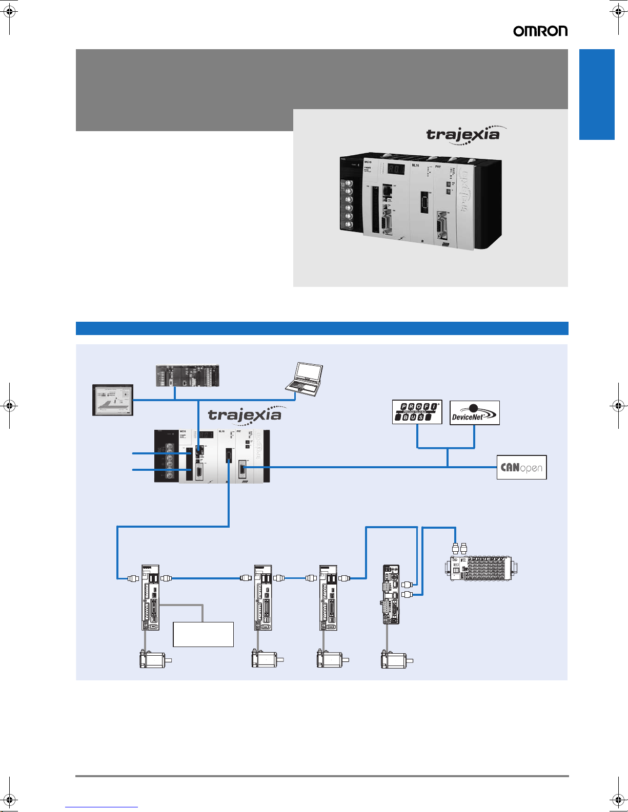
System configuration
Motion controllers
NS-series
HMI
Digital I/Os
Host-link
Accurax G5 series
Servo motors
CJ-series PLC
Motion controller
Accurax G5 series
Servo drive
Input
Fast registration
inputs, home and
limits switches...
Ethernet
Personal computer software:
CX-One (CX-Motion Pro)
Trajexia Studio
PROFIBUS-DP
Fieldbus
MECHATROLINK-II
G- Series
Servo drive
AC SERVO DRIVER
ADR
1
1
0
0
9
2
2
8
3
3
7
4
6
5
X10
X1
COM
SP
IM
G
G-Series
Servo motors
Master
DeviceNet
Master
Terminator
GRT1-ML2
SW1 SW2
CN2
CN1
A/B
SmartSlice IOs
CANopen
Devices
23Trajexia motion controller
Page 2
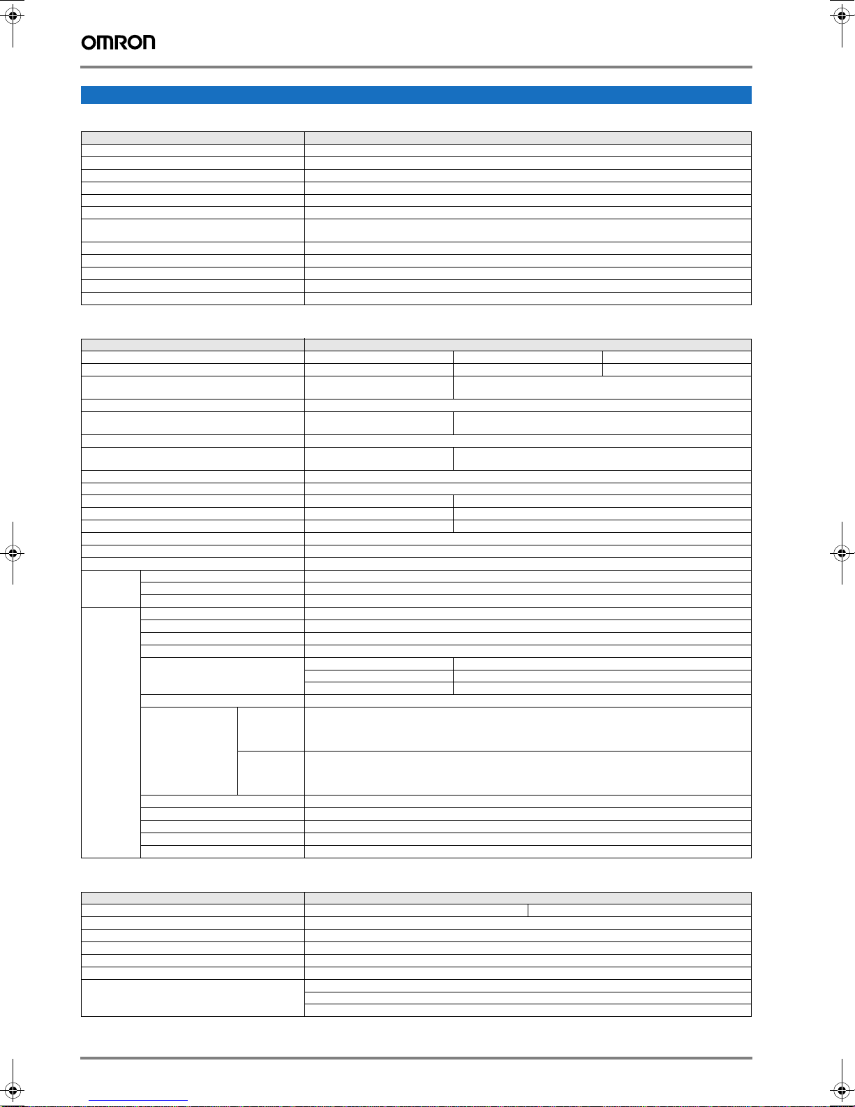
Specifications
Trajexia general specifications
Item Details
Model TJ@
Ambient operating temperature 0 to 55°C
Ambient operating humidity 10 to 90%RH
Ambient storage temperature -20 to 70°C
Ambient storage humidity 90% max. (with no condensation)
Atmosphere No corrosive gases
Vibration resistance 10 to 57 Hz: (0.075 mm amplitude)
Shock resistance 143 m/s
Insulation resistance 20 MOhm
Dielectric strength 500 Volt
Protective structure IP20
International standards CE, EN 61131-2, cULus, Lloyds, RoHS compliant
57 to 100 Hz Acceleration: 9,8 m/s
2
, 3 times each X, Y and Z directions.
Trajexia motion control units
Item Details
Model TJ2-MC64 TJ1-MC16 TJ1-MC04
Number of axes 64 16 4 (+1 using TJ1-FL02 unit)
Number of inverters and I/O modules Up to 64 (Inverters in position,
Number of MECHATROLINK-II master units Up to 4 MECHATROLINK-II master units (see below TJ1-ML16/ML04) can be connected
Cycle time Selectable 0.25 ms, 0.5 ms, 1 ms or
Programming language BASIC-like motion language
Multi-tasking Up to 22 tasks running simulta-
Built-in digital I/O 16 inputs and 8 outputs, for general purpose
Measurement units User definable
Available memory for user programs 8 MB 500 KB
Data storage capacity Up to 32 MB Flash data storage Up to 2 MB Flash data storage
Saving program data, motion controller Flash-ROM SRAM with battery backup and Flash-ROM
Saving program data, personal computer Via CX-Motion Pro/Trajexia Studio software
Communication ports 1 Ethernet port and 2 serial ports
Firmware update Via CX-Motion Pro/Trajexia Studio software
Ethernet port Electrical characteristics Conform to IEEE 802.3 (100BaseT)
Serial port Electrical characteristics Conform 1 port to RS232C and 1 port to RS485/RS422A (selectable by switch)
Connector RJ45 Ethernet connector
Transmission protocol Modbus TCP slave
Connector SUB-D9 connector (Counterpart included in the package)
Synchronization Start-stop synchronization (asynchronous)
Baud rate 1200 / 2400 / 4800 / 9600 / 19200 / 38400 bps
Transmission format Databit length 7 or 8 bit
Transmission mode Point-to-multipoint (1:N)
Transmission protocol RS-232C (1:1) Host Link master protocol,
RS-485 (1:N)
RS-422A (1:N)
Galvanic isolation RS422A port
Communication buffers 254 bytes
Flow control None
Terminator Yes, selectable by switch
Cable length 15 m for RS232 and 500 meter for RS422/485
speed or torque mode)
2 ms
neously
Stop bit 1 or 2 bit
Parity bit Even/Odd/None
Host Link slave protocol,
ASCII general-purpose,
Modbus TCP slave
Host Link master protocol,
Host Link slave protocol,
ASCII general-purpose,
Modbus TCP slave
2
, in X, Y and Z directions for 80 minutes.
8 maximum (Inverters in position, speed or torque mode)
Selectable 0.5 ms, 1 ms or 2 ms
Up to 14 tasks running simultaneously
Trajexia MECHATROLINK-II master units
Item Specifications
Model TJ1-ML16 TJ1-ML04
Controlled devices with MECHATROLINK-II interface Accurax G5 and G-Series servo drives ML-II built-in and SmartSlice IOs
Electrical characteristics Conforms to MECHATROLINK standard
Communication ports 1 MECHATROLINK-II master
Transmission speed 10 Mbps
Communication cycle 0.5 ms, 1 ms or 2 ms
Stations slave types Axes or servo drives
24 Motion Control
Frequency inverters
I/O modules
Page 3
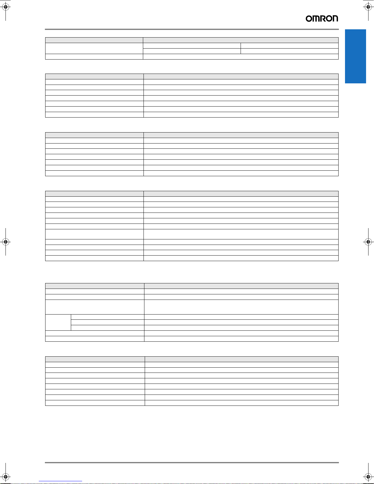
Item Specifications
Number of stations per master / Cycle time Max.16 Stations/2 ms Max. 4 Stations/2 ms
Transmission distance Max. 50 meters without using repeater
Max. 8 Stations/1 ms Max. 4 Stations/1ms
Trajexia PROFIBUS slave unit
Items Specifications
Model TJ1-PRT
PROFIBUS standard Conforms to PROFIBUS-DP standard EN50170 (DP-V0)
Communication ports 1 PROFIBUS-DP sl ave
Transmission speed 9.6, 19.2, 45.45, 93.75, 187.5, 500, 1500, 3000, 6000 and 12000kbps
Node numbers 0 to 99
I/O size 0 to 122 words (16 bit), configurable, for both directions
Galvanic isolation Yes
Trajexia DeviceNet slave unit
Items Specifications
Model TJ1-DRT
PROFIBUS standard Conforms to DeviceNet standard of CIP edition 1
Communication ports 1 DeviceNet slave
Transmission speed 125, 250 and 500 Kbps, auto-detect
Node numbers 0 to 63
I/O size 0 to 32 words (16 bit), configurable, for both directions
Galvanic isolation Yes
Trajexia CANopen unit
Items Specifications
Model TJ1-CORT
Electrical Characteristics Conforms to CAN 2.0 B
Communication ports 1 CANopen
Transmission speed 20, 50, 125 and 500 Kbps
Implemented CiA Standards DS301, DS302
PDO Support 8 TPDO and 8 RPDO
PDO Mapping Each PDO can be mapped into TJ1-MC16/04 VR, table, analogue and digital IO.
CANopen slave configuration Any SDO message can be sent using BASIC during start-up and operation
CANopen network states CANopen network can be set to pre-operational and operat i onal using BASIC
CANopen slave emergencies Available using BASIC command
Galvanic isolation Yes
*1. TJ2-MC64 and TJ1-MC16/04 CPUs support a total of 256 digital IO points and 36 analogue IO points.
BASIC commands assign mapping and start address
*1
Motion controllers
Trajexia flexible axis unit
Items Specifications
Model TJ1-FL02
Number of axes 2. Every axis has 1 analog output, 1 encoder in/out -software configurable - and several digit al I/O
Control methods
(independent per axis)
Encoder Encoder protocols Abs SSI 200 kHz, Abs EnDat 1 MHz, Abs Tamagawa and Incremental Line driver AB
Auxiliary I/Os 2 fast registration inputs, 2 definable inputs, 2 enable output, 4 position switch outputs or axes reset
Galvanic isolation Yes
Encoder Input maximum frequency 6 MHz
Encoder/pulse output max. frequency 2 MHz
±10 V analogue output + encoder input (closed loop)
Line driver AB output
Stepper pulse output in closed loop or pulse train output in open loop
SmartSlice MECHATROLINK-II interface unit
Item Specifications
Model GRT1-ML2
Electrical characteristics Conform to MECHATROLINK standard
Communication cycle 0.5, 1 or 2 ms
Power supply 24 VDC
Number of connectable Slices Up to 64 slices with a maximum amount of 128 bytes
IO mapping Automatic analogue and digital IO mapping into TJ1-MC16/04 CPU
Slice unit configuration Not supported
Supported slice units See ordering information section
*1. TJ2-MC64 and TJ1-MC16/04 CPUs support a total of 256 digital IO points and 36 analogue IO points.
*1
Trajexia motion controller 25
Page 4

Nomenclature
Trajexia motion controller unit - TJ2-MC64, TJ1MC-16/04
LEDs
Battery
compartment
Digital I/O
connector
Display
Ethernet port
RS422A/RS485
switches
RS-232C and
RS422A/485
serial ports
Trajexia DeviceNet slave unit - TJ1-DRT
Unit LEDs
3
2
4
1
5
0
6
9
7
8
3
2
4
1
5
0
6
9
7
8
Node selection
Trajexia MECHATROLINK-II master unit - TJ1-ML16/04
ML16
RUN
8F
CN1
Unit LEDs
MECHATROLINK-II master port
Trajexia CANopen unit - TJ1-CORT
CORT
Unit LEDs
3
2
4
1
5
0
6
9
7
8
3
2
4
1
5
0
6
9
7
8
Node selection
V-
CAN L
DRAIN
CAN H
V+
Trajexia PROFIBUS-DP unit - TJ1-PRT
H
B
3
2
4
1
5
0
6
9
7
8
3
2
4
1
5
0
6
9
7
8
DeviceNet slave port
Unit LEDs
PROFIBUS node
selection
PROFIBUS-DP slave port
V-
CAN L
DRAIN
CAN H
V+
Trajexia Flex axis unit - TJ1-FL02
FL02
CANopen port
Unit LEDs
15 pin connector
(Encoders IN/Out)
18 pin connector
(Digital and Analogue IOs)
26 Motion Control
Page 5

SmartSlice MECHATROLINK-II interface unit - GRT1-ML2
GRT1-ML2
SW1
SW2
CN2
CN1
A/B
RUN
ALARM
ML COM
TS
UNIT PWR
I/O PWR
ON
MECHATROLINK-II node selection
Unit LEDs
FG connector
REGS
1
NC2
ADR
3
BACK4
UNIT
+V
-V
I/O
+V
-V
DC24V
INPUT
Slice-master switches
ML vonnectors
Unit power
IO power
Dimensions
Trajexia motion controller - TJ2-MC64, TJ1-MC16/04 Trajexia modules - TJ1-ML16/04, -PRT, -DRT, -CORT, -FL02
94
90
94
90
Motion controllers
65
70.3
62
71
Trajexia system - CJ1W-PA202 + TJ1-MC16 + one module + TJ1-TER
65
PA202
70.30
31
39.9
94
90
Trajexia motion controller 27
62
29.73145
Page 6

SmartSlice communication unit - GRT1-ML2
SmartSlice end unit - GRT1-END
SmartSlice I/O units - GRT1-_
28 Motion Control
Page 7

Ordering information
Motion controllers
Power
Supply
Motion
controller
Axes
control
Communication
slave
End cover
(Included into the Motion controller)
Trajexia motion controller
Name Model
Trajexia motion controller unit, up to 4 axes. (Trajexia end cover unit TJ1-TER is included) TJ1-MC04
Trajexia motion controller unit, up to 16 axes. (Trajexia end cover unit TJ1-TER is included) TJ1-MC16
Trajexia motion controller Unit, up to 64 axes. (Trajexia end cover unit TJ1-TER is included) TJ2-MC64
Power supply for Trajexia system, 100-240 VAC CJ1W-PA202
Power supply for Trajexia system, 24 VDC CJ1W-PD022
Trajexia - axes control modules
Name Model
Trajexia MECHATROLINK-II master unit (up to 4 stations) TJ1-ML04
Trajexia MECHATROLINK-II master unit (up to 16 stations) TJ1-ML16
Trajexia flexible axis unit (for 2 axes) TJ1-FL02
Note: The TJ1-ML04 and TJ1-ML16 supported by the TJ2-MC64 motion controller are V2 (Version 2) and lot number equal
or above Lot No.091019 (YYMMDD).
Trajexia - communication modules
Name Model
Trajexia DevicNet slave unit TJ1-DRT
Trajexia PROFIBUS-DP slave unit TJ1-PRT
Trajexia CANopen unit TJ1-CORT
MECHATROLINK-II - related devices
Servo system & frequency inverters
Name Model
Accurax G5 servo drive ML-II built-in R88D-KN@@@-ML2
G-Series servo drive ML-II built-in R88D-GN@@H-ML2
Note: Refer to servo systems section for detailed specs and ordering information
SmartSlice IOs system
Function Specification Model
SmartSlice Interface unit SmartSlice MECHATROLINK-II inteface unit GRT1-ML2
End plate, one unit required per bus interface GRT1-END
4 NPN inputs 24 VDC, 6 mA, 3-wire connection GRT1-ID4
4 PNP inputs 24 VDC, 6 mA, 3-wire connection GRT1-ID4-1
8 NPN inputs 24 VDC, 4 mA, 1-wire connection + 4xG GRT1-ID8
8 PNP inputs 24 VDC, 4 mA, 1-wire connection + 4xV GRT1-ID8-1
4 NPN outputs 24 VDC, 500 mA, 2-wire connection GRT1-OD4
4 PNP outputs 24 VDC, 500 mA, 2-wire connection GRT1-OD4-1
4 PNP outputs with short-circuit protection 24 VDC, 500 mA, 3-wire connection GRT1-OD4G-1
8 NPN outputs 24 VDC, 500 mA, 1-wire connection + 4xV GRT1-OD8
8 PNP outputs 24 VDC, 500 mA, 1-wire connection + 4xG GRT1-OD8-1
8 PNP outputs with short-circuit protection 24 VDC, 500 mA, 1-wire connection + 4xG GRT1-OD8G-1
2 relay outputs 240 VAC, 2 A, normally-open contacts GRT1-ROS2
2 analogue inputs, current/voltage ±10 V, 0-10 V, 0-5 V, 1-5 V, 0-20 mA, 4-20 mA GRT1-AD2
2 analogue outputs, voltage ± 10 V, 0-10 V, 0-5 V, 1-5 V GRT1-DA2V
2 analogue outputs, current 0-20 mA, 4-20 mA GRT1-DA2C
Note: Refer to Automation systems catalogue for detailed specs and accesories information
Trajexia motion controller 29
Page 8

MECHATROLINK-II cables
Name Remarks Model
MECHATROLINK-II cables 0.5 meter JEPMC-W6003-A5
MECHATROLINK-II terminator Terminating resistor JEPMC-W6022
MECHATROLINK-II repeater Network repeater JEPMC-REP2000
1 meter JEPMC-W6003-01
3 meters JEPMC-W6003-03
5 meters JEPMC-W6003-05
10 meters JEPMC-W6003-10
20 meters JEPMC-W6003-20
30 meters JEPMC-W6003-30
Computer software
Specifications Model
CX-Motion Pro V1.22 or higher CX-One
Trajexia Studio
*1. When the Trajexia Studio software is included in CX-One, then it is called CX-Motion Pro.
*1
V1.22 or higher
TJ1-Studio
ALL DIMENSIONS SHOWN ARE IN MILLIMETERS.
To convert millimeters into inches, multiply by 0.03937. To convert grams into ounces, multiply by 0.03527.
Cat. No. I53E-EN-03A
In the interest of product improvement, specifications are subject to change without notice.
30 Motion Control
 Loading...