

Page 1
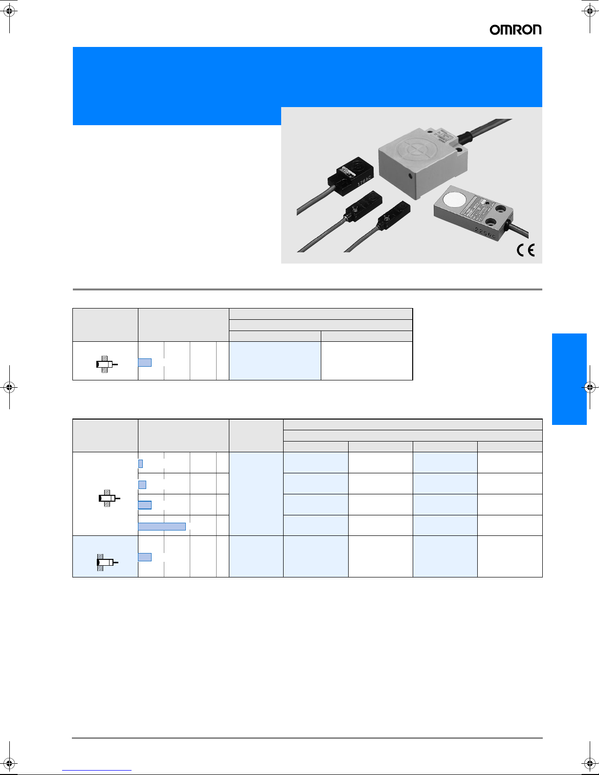
Standard Flat Inductive Proximity Sensors
TL-W
• Front and side facing surface
•IP67
• DC 2-wire and DC 3-wire models
Ordering Information
DC 2-wire Models
Shape Sensing distance
Output and operating status
NO NC
Model
5mm
*1. Models with different response frequency are available. These model numbers take the form TL-W5MD#5 (e.g., TL-
W5MD15)
TL-W5MD1
*1
TL-W5MD2
*1
DC 3-wire Models
Shape Sensing distance
1.5mm
3mm
5mm
20mm
Shielded
5mm
*1. Models with different response frequency are available. These model numbers take the form TL-W5MD#5 (e.g., TL-W5MD15)
Output
specifications
DC 3-wire
DC 3-wire TL-W5F1 TL-W5F2 TL-W5E1 TL-W5E2
PNP-NO PNP-NC NPN-NO NPN-NC
TL-W1R5MB1 --- TL-W1R5MC1
TL-W3MB1 TL-W3MB2 TL-W3MC1
TL-W5MB1 TL-W5MB2 TL-W5MC1
--- --- TL-W20ME1*1TL-W20ME2
Output and operating status
Model
*1
*1
*1
TL-W
---
TL-W3MC2
TL-W5MC2
*1
D-53TL-W
Page 2
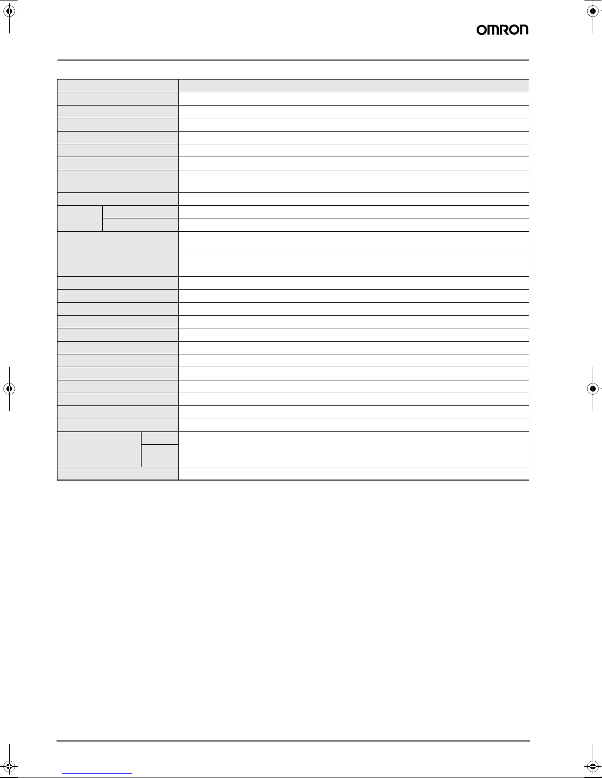
Rating/Performance
DC 2-wire Models
Item Model TL-W5MD#
Sensing distance 5 mm ±10%
Setting distance
Differential distance 10% max.
Sensing object Ferrous metal(Sensitivity decreases with non-ferrous metals)
Standard sensing object Iron, 18 x 18 x 1 mm
Response frequency 0.5 kHz
Rated supply voltage
(operating voltage)
Leakage current 0.8 mA max.
Control
output
Indicator lamp
Operating status
(with sensing object approaching)
Protective circuits Surge absorber, short-circuit protection
Ambient temperature Operating/Storage: -25°C to 70°C (with no icing or condensation)
Ambient humidity Operating/Storage: 35% to 95%RH (with no condensation)
Temperature influence ±10% max. of sensing distance at 23°C within a temperature range of -25°C and 70°C
Voltage influence ±2.5% max. of Sensing distance within a rated voltage range ±15%.
Insulation resistance 50 M min. (at 500 VDC) between energized parts and case
Dielectric strength 1,000 VAC for 1 min between energized parts and case
Vibration resistance 10 to 55 Hz, 1.5 mm double amplitude for 2 hours each in X, Y, and Z directions
Shock resistance Destruction: 500 m/s2 for 3 times each in X, Y, and Z directions
Protective structure IEC60529 IP67
Connection method Pre-wired models (standard length: 2 m)
Weight (Packed state) Approx. 45 g
Material
Accessories Instruction manual
* The response frequencies for DC switching are average values measured under the condition that the distance between each sensing object is twice as large as the
size of the sensing object and the sensing distance set is half of the maximum sensing distance.
Switching capacity 3 to 100 mA
Residual voltage 3.3 V max. (under load current of 100 mA with cable length of 2 m)
Case
Sensing
surface
0 to 4 mm
12 to 24 VDC (10 to 30 VDC), ripple (p-p): 10% max.
D1 models: Operation indicator (Red LED), Operation set indicator (Green LED)
D2 models: Operation indicator (Red LED)
D1 models: NO
D2 models: NC
Heat-resistant ABS resin
D-54 Inductive Sensors
Page 3
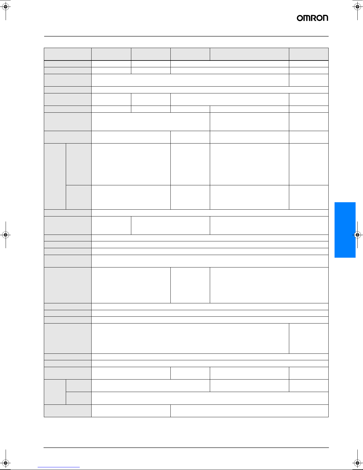
DC 3-wire Models
Item
Sensing distance 1.5 mm ±10% 3 mm ±10% 5 mm ±10% 20 mm ±10%
Setting distance
Differential distance 10% max.
Sensing object Ferrous metal (refer to Engineering Data for non-ferrous metal on page E-55)
Standard sensing
object
Response frequency 1 kHz min. 600 Hz min. 500 Hz min. 300 Hz min. 40 Hz min.
Power supply
(Operating voltage
range)
Current consumption 15 mA max. at 24 VDC (no-load) 10 mA max. 15mA max. at 24 VDC (no-load)
Control
output
Indicator lamp Detection indicator (red LED)
Operating status
(with sensing object
approaching)
Protective circuits Reverse connection protection, surge absorber
Ambient temperature Operating/Storage: -25°C to 70°^C (with no icing or condensation)
Ambient humidity Operating/Storage: 35% to 95%RH (with no condensation)
Temperature influ-
ence
Voltage influence
Insulation resistance 50 M min. (at 500 VDC) between energized parts and case
Dielectric strength 1000 VAC 50/60 Hz for 1 min between energized part and case
Vibration resistance 10 to 55 Hz, 1.5 mm double amplitude for 2 hours each in X, Y, and Z directions
Shock resistance Destruction: 500 m/s2 for 3 times each in X, Y, and Z directions
Protective structure IEC60529 IP67
Connection method Pre-wired models (standard length: 2 m)
Weight
(Packed state)
Material
Accessories
Model
Switching
capacity
Residual
voltage
Case Heat-resistant ABS resin Diecast aluminum
Sensing
surface
TL-W1R5M#1 TL-W3M## TL-W5M## TL-W5E#/F# TL-W20ME#
0 to 1.2 mm
Iron, 8 x 8 x 1 mm
12 to 24 VDC (10 to 30 VDC) ripple (p-p): 10% max.
NPN open collector 100 mA max.
(30 VDC max.)
1 V max. (under load current of
100 mA with cable length of 2 m)
NO
±10% max. of sensing distance at 23°C within the temperature range of -25°C and 70°C
±2.5% max. of sensing distance
within a range of ±10% of rated
power supply voltage
30 g Approx. 45 g Approx. 70 g Approx. 180 g
Heat-resistant ABS resin
Mounting bracket,
instruction manual
0 to 2.4 mm 0 to 4 mm 0 to 16 mm
1% to 15% of
sensing distance
Iron, 12 x 12 x
1 mm
C1 models: NO
C2 type: NC
Iron, 18 x 18 x 1 mm
NPN open collector 12 VDC
50 mA max.
(30 VDC max.)
24 VDC 100 mA
max. (30 VDC
max.)
1 V max. (under
load current of
50 mA with cable
length of 2 m)
±2.5% max.
of sensing distance within a
range of ±20%
of rated power
supply voltage
Instruction manual
10 to 30 VDC with a ripple (p-p) of
20% max.
200 mA
2 V max. (under load current of
200 mA with cable length of 2 m)
E1 models, F1 models: NO
E2 models, F2 models: NC
±2.5% max. of sensing distance within a range of ±10%
of rated power supply voltage
Iron, 50 x 50 x
1 mm
12 to 24 VDC (10
to 30 VDC) ripple
(p-p): 10% max.
8 mA at 12 VDC,
15 mA at 24 VDC
12 VDC
100mA max.,
24 VDC
200 mA max.
1 V max. (under
load current of
200 mA with cable length of 2 m)
Destruction:
500 m/s2 for 10
times each in X,
Y, and Z directions
Heat-resistant
ABS resin
TL-W
D-55TL-W
Page 4

Characteristic data (typical)
Sensing Distance vs. Sensing Object
TL-W1R5M# TL-W3M# TL-W5MB#/C#
4
#
d
t=
mm
1
X
3
Sensing distance X (mm)
2
Iron
1
0
Stainless steel (SUS304)
Brass
Copper
Aluminum
10 20 30 40 50 60
Side length of sensing object d (mm)
TL-W5E#/-W5F#/-W5MD# TL-W20#
6
#
d
t
mm
=1
X
5
4
Sensing distance X (mm)
3
2
1
0
5 1015202530 354045
Stainless steel (SUS304)
Side length of sensing object d (mm)
Iron
Brass
Aluminum
4
3
Sensing distance X (mm)
2
1
0
10 20 30 40 50 60
24
#
d
22
20
18
16
14
Sensing distance X (mm)
12
10
X
8
6
4
2
0
10 20 30 40 50 60 70 80 90
Stainless steel (SUS304)
Side length of sensing object d (mm)
t
mm
=1
Stainless steel (SUS304)
Side length of sensing object d (mm)
Aluminum
Brass
Aluminum
Iron
Brass
Copper
Iron
7
#
d
6
5
4
Sensing distance X (mm)
3
2
1
0 102030405060
t=
X
mm
1
Iron
Stainless steel (SUS304)
Brass
Aluminum
Copper
Side length of sensing object d (mm)
D-56 Inductive Sensors
Page 5

Output Circuit Diagram
DC 2-wire Models
Operating
status
NO TL-W5MD1
NC TL-W5MD2
DC 3-wire Models
Operating
status
NO
NC
Model Timing chart Output circuit
Model Timing chart Output circuit
TL-W1R5M#1
TL-W3M#1
TL-W5M#1
TL-W3M#2
TL-W5MC2
Non-sensing
zone
Sensing object
(%) 100 080(TYP)
Rated sensing distance
Sensing
object
(%) 0
Rated sensing distance
Setting position
Stable sensing
Unstable
Sensing zone
Sensing zoneNon-sensing zone
100
Sensing object
Output transistor
(load)
Operation indicator
Operation indicator
(red)
Sensing object
Output transistor
(load)
(red)
zone
Yes
OFF
OFF
Yes
OFF
OFF
No
ON
ON
No
ON
ON
Proximity Sensor
ON
Setting indicator (green)
OFF
ON
Operation indicator (red)
OFF
ON
Control output
OFF
Proximity Sensor
ON
Operation indicator (red)
OFF
ON
Control output
OFF
Brown
Load
+V
Main
circuit
Blue
Brown
Black
Output
Blue
*
0V
+V
Load
0V
Note:
The Load can be connected to either the +V and 0-V side.
100W
Main
circuit
* Maximum load current: 100 mA
TL-W
NO
NC
NO
NC
TL-W1R5B1
TL-W3MB1
TL-W5MB1
TL-W3MB2
TL-W5MB2
TL-W5E1
TL-W20ME1
TL-W5E2
TL-W20ME2
Sensing object
Output transistor
Operation indicator
Sensing object
Output transistor
Operation indicator
(between brown and black)
(between blue and black)
Operation indicator (red)
(between brown and black)
(between blue and black)
Operation indicator (red)
Yes
ON
OFF
(load)
ON
OFF
(red)
Yes
ON
(load)
OFF
ON
OFF
(red)
Sensing object
Load
Output voltage
Sensing object
Load
Output voltage
No
No
Yes
Operate
Release
OFF
Yes
Operate
Release
OFF
Brown
Main
circuit
No
H
L
ON
No
H
L
ON
Main
circuit
* Maximum load current: 100 mA
* 2. Current flows in this direction
if the circuit incorporates the transistor.
100W
4.7kW
100W
2.2W
Black
Blue
Brown
Black
Output
Blue
+V
Load
0V
+V
Load
*1
*2
Tr
0V
D-57TL-W
Page 6

Operating
status
NO TL-W5F1
NC TL-W5F2
Model Timing chart Output circuit
Sensing object
Operate
(between brown and black)
(between blue and black)
Operation indicator (red)
(between brown and black)
Load
Output voltage
Sensing object
Load
Output voltage
(between blue and black)
Operation indicator (red)
Release
Operate
Release
Precautions
Correct Use
Design
Effects of Surrounding Metal
Provide a minimum distance between the Sensor and the surrounding metal as shown in the table below.
Front Surface Sensing Type (Not exceeding the sensor head
height).
Yes
No
ON
OFF
OFF
H
L
Yes
No
H
L
ON
Main
circuit
* 1. Maximum load current: 200 mA
* 2. Current flows in this direction
if the circuit incorporates the transistor.
4.7kW
2.2W
100W
Mutual Interference
If two or more Sensors are mounted face to face or side by side,
keep them separate at the following minimum distance.
A
B
Brown
Black
Output
Blue
+V
Tr
*2
*1
Load
0V
m
Sensing surface
Proximity Sensor
Sensing
B
surface
ll
Proximity Sensor
Effects of Surrounding Metal(Unit: mm)
Model
TL-W1R5M# 2
TL-W3M#
TL-W5MD#
TL-W5M#
TL-W20ME# 25 16 100
TL-W5E#/-W5F# 0020
Length
l m n
8
3
0
12
520
Mutual Interference (unit: mm)
Model
TL-W1R5M# 75 (50) 120(60)
TL-W3MC# 90 (60) 200(100)
TL-W5MD#
TL-W5MC#
TL-W20ME# 200(100) 200(100)
TL-W5E#/-W5F# 50 35
Note: The above values in parentheses are applicable when using two sensors
with different frequencies.
Length
A B
120(80) 60(30)
Installation
• Use M3 flat-head screws to install TL-W1R5M# and
•TL-W3M#.
• Ensure that the resin cover should be tightened with
• a torque according to the following table.
Model Tensile strength (torque)
TL-W1R5MC1
TL-W3MC#
0.98 Nm
TL-W5MD#
TL-W20M# 1.5 Nm
● Adjustment
Power ON
Please note that the power injection AND connection generate an error pulse for approximately 1 ms.
D-58 Inductive Sensors
Page 7

Dimensions (Unit: mm)
TL-W1R5M#1
Mounting Bracket
(Attachment)
1
7.8
5
Note:
R1.6
3.2
22.4
16
(See note)
R1.6
8
7
Mounting dimensions: 17
TL-W5M##
25
0.2
±
16
0.2
5±
3
Operation indicator
Mounting hole for
M3 pan-head screw
90
˚
6 dia.
Indicator
Indicator
0.1
±
12
7.5
6.5
(red)
*
8
8
Sensing surface
5.5
3.2
*
Vinyl-insulated round cable with three conductors, 2.9 dia.
(conductor cross-sectional area: 0.15 mm²; insulation
diameter: 0.9 mm);
standard length: 2 m
±0.2
Sensing
surface
18
10
* 1. TL-W5MC1: Vinyl-insulated round cable with
three conductors, 4 dia. (conductor cross-sectional area:
0.2 mm
TL-W5MD# : Vinyl-insulated round cable with two conductors,
4 dia. (conductor cross-sectional area: 0.3 mm²; insulation
diameter: 1.3 mm); standard length: 2 m
* 2. C type: Operation indicator (red)
D type: Operation indicator (red), Setting indicator (green)
30.5
8.5
18
5
Indicator * 2
12.5
2
; insulation diameter: 1.2 mm); standard length: 2 m
89
3.2 dia.
4.5
*1
4
3.5
TL-W3M##
Mounting Bracket
(Attachment)
7.8
1
5.5
R1.6
22.4
16
(See note)
R1.6
3.2
10
9
Note: Mounting dimensions: 17±0.2
TL-W5E#
TL-W5F#
Operation indicator (red)
0
24.9
-0.4
Mounting Holes
0.2
15±
Two, 4.5 dia.
10
27
0.2
±
17
0.2
5±
10
Sensing surface
6
3.2
10
15
16 dia.
Sensing surface
3
4
* Vinyl-insulated round cable with three conductors,
4 dia. (conductor cross-sectional area: 0.2mm
insulation diameter: 1.2 mm); standard length: 2 m
3.2 dia.
* Vinyl-insulated round cable with three conductors,
2.9 dia. (conductor cross-sectional area: 0.14 mm
insulation diameter: 0.9 mm); standard length: 2 m
10.5
50
89
90˚
6 dia.
8
4.2 dia.
7.2 dia.
3
Operation indicator
(red)
Mounting hole for M3
pan-head screw
Indicator
Indicator
4.5
(2)
2
;
(See note)
*
2
;
TL-W
TL-W20ME#
Operation indicator (red)
Sensing surface
0.1
40
18
±
30
5
0.1
27±
5
23
1
18
53
620
Two, 5.5 dia. mounting holes
Vinyl-insulated round cable with three conductors,
1.5
6 dia. (conductor cross-sectional area: 0.5 mm
insulation diameter: 1.9 mm); standard length: 2 m
2
;
D-59TL-W
Page 8

ALL DIMENSIONS SHOWN ARE IN MILLIMETERS.
To convert millimeters into inches, multiply by 0.03937. To convert grams into ounces, multiply by 0.03527.
Cat. No. E221-E2-03-X
In the interest of product improvement, specifications are subject to change without notice.
D-60 Inductive Sensors
 Loading...