

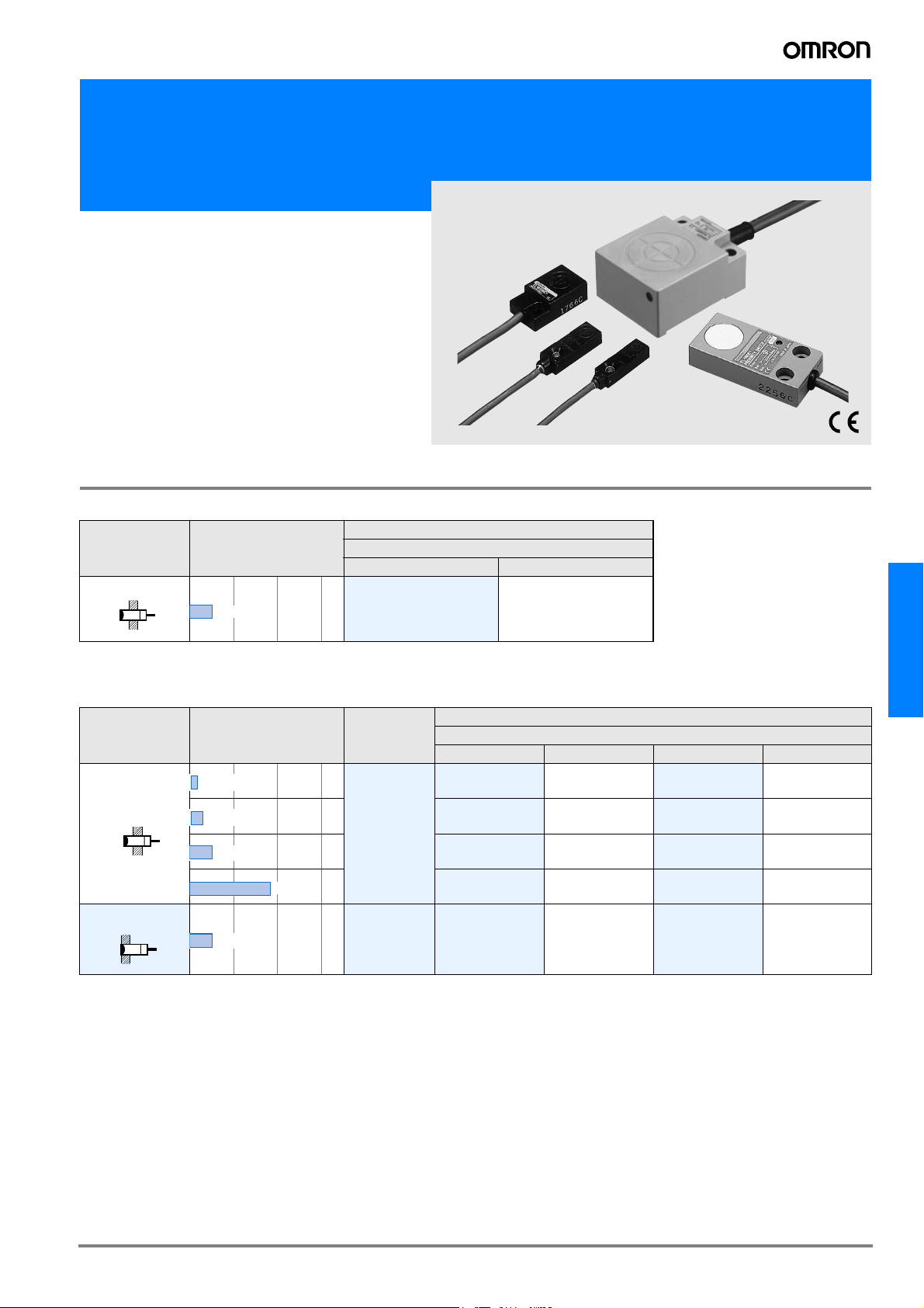
Standard Flat Inductive Proximity Sensors
TL-W
• Front and side facing surface
•IP67
• DC 2-wire and DC 3-wire models
Ordering Information
DC 2-wire Models
Shape Sensing distance
Output and operating status
NO NC
Model
5mm
*1. Models with different response frequency are available. These model numbers take the form TL-W5MD#5 (e.g., TL-
W5MD15)
TL-W5MD1
*1
TL-W5MD2
*1
DC 3-wire Models
Shape Sensing distance
1.5mm
3mm
5mm
20mm
Shielded
5mm
*1. Models with different response frequency are available. These model numbers take the form TL-W5MD#5 (e.g., TL-W5MD15)
Output
specifications
DC 3-wire
DC 3-wire TL-W5F1 TL-W5F2 TL-W5E1 TL-W5E2
PNP-NO PNP-NC NPN-NO NPN-NC
TL-W1R5MB1 --- TL-W1R5MC1
TL-W3MB1 TL-W3MB2 TL-W3MC1
TL-W5MB1 TL-W5MB2 TL-W5MC1
--- --- TL-W20ME1
Output and operating status
Model
*1
*1
*1
*1
---
TL-W3MC2
TL-W5MC2
TL-W20ME2
TL-W
*1
D-53TL-W
Rating/Performance
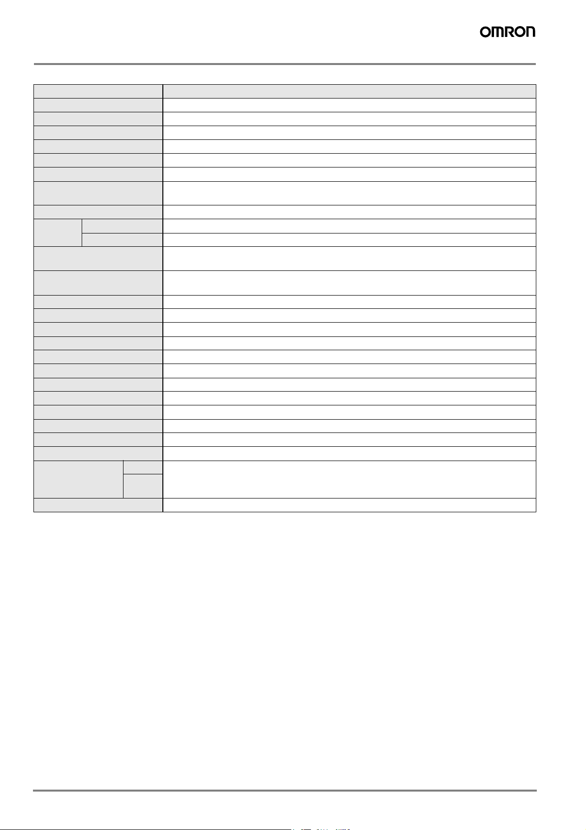
DC 2-wire Models
Item Model TL-W5MD#
Sensing distance 5 mm ±10%
Setting distance
Differential distance 10% max.
Sensing object Ferrous metal(Sensitivity decreases with non-ferrous metals)
Standard sensing object Iron, 18 x 18 x 1 mm
Response frequency 0.5 kHz
Rated supply voltage
(operating voltage)
Leakage current 0.8 mA max.
Control
output
Indicator lamp
Operating status
(with sensing object approaching)
Protective circuits Surge absorber, short-circuit protection
Ambient temperature Operating/Storage: -25°C to 70°C (with no icing or condensation)
Ambient humidity Operating/Storage: 35% to 95%RH (with no condensation)
Temperature influence ±10% max. of sensing distance at 23°C within a temperature range of -25°C and 70°C
Voltage influence ±2.5% max. of Sensing distance within a rated voltage range ±15%.
Insulation resistance 50 M min. (at 500 VDC) between energized parts and case
Dielectric strength 1,000 VAC for 1 min between energized parts and case
Vibration resistance 10 to 55 Hz, 1.5 mm double amplitude for 2 hours each in X, Y, and Z directions
Shock resistance Destruction: 500 m/s2 for 3 times each in X, Y, and Z directions
Protective structure IEC60529 IP67
Connection method Pre-wired models (standard length: 2 m)
Weight (Packed state) Approx. 45 g
Material
Accessories Instruction manual
* The response frequencies for DC switching are average values measured under the condition that the distance between each sensing object is twice as large as the
size of the sensing object and the sensing distance set is half of the maximum sensing distance.
Switching capacity 3 to 100 mA
Residual voltage 3.3 V max. (under load current of 100 mA with cable length of 2 m)
Case
Sensing
surface
0 to 4 mm
12 to 24 VDC (10 to 30 VDC), ripple (p-p): 10% max.
D1 models: Operation indicator (Red LED), Operation set indicator (Green LED)
D2 models: Operation indicator (Red LED)
D1 models: NO
D2 models: NC
Heat-resistant ABS resin
D-54 Inductive Sensors
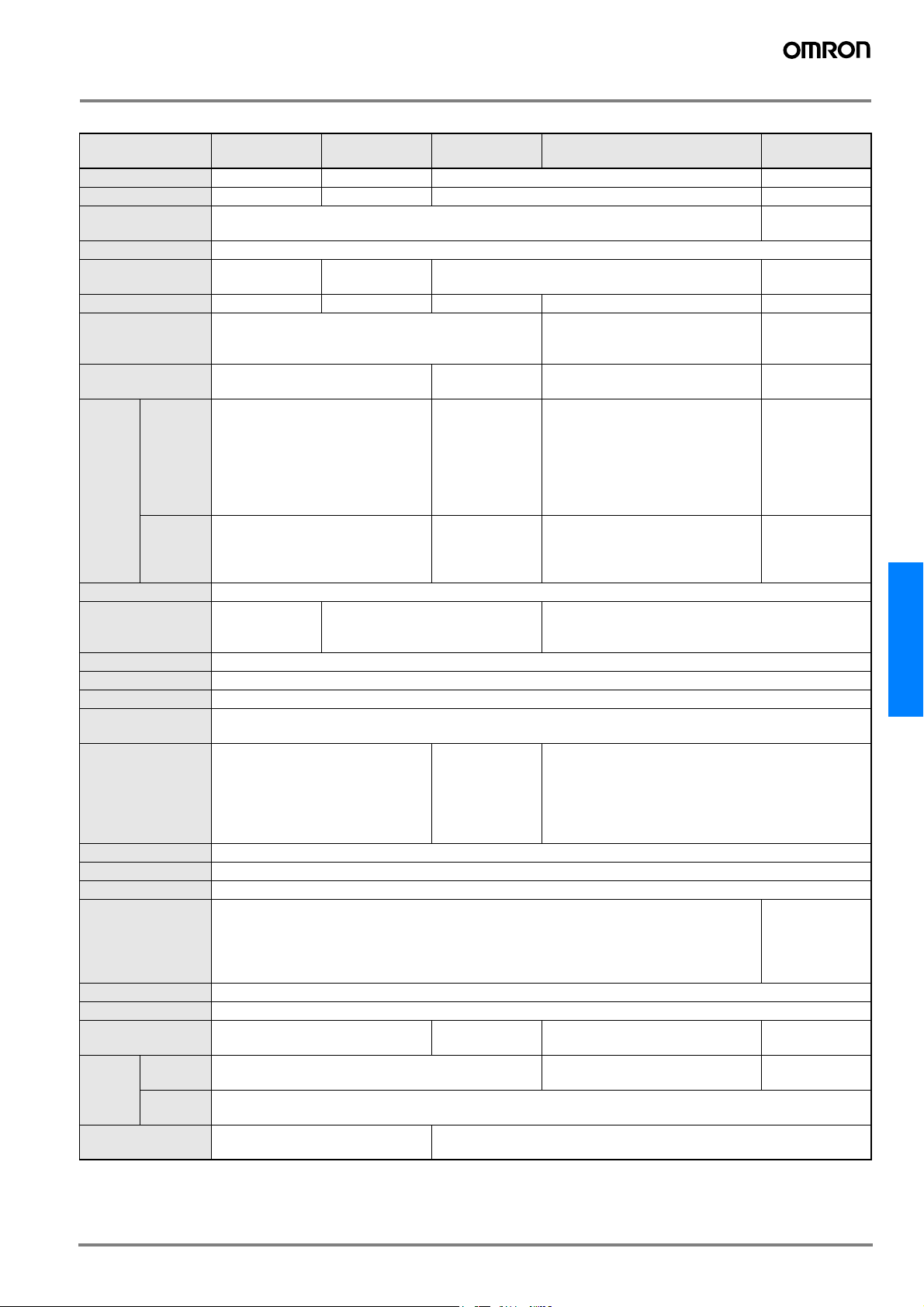
DC 3-wire Models
Model
Item
Sensing distance 1.5 mm ±10% 3 mm ±10% 5 mm ±10% 20 mm ±10%
Setting distance
Differential distance 10% max.
Sensing object Ferrous metal (refer to Engineering Data for non-ferrous metal on page E-55)
Standard sensing
object
Response frequency 1 kHz min. 600 Hz min. 500 Hz min. 300 Hz min. 40 Hz min.
Power supply
(Operating voltage
range)
Current consumption 15 mA max. at 24 VDC (no-load) 10 mA max. 15mA max. at 24 VDC (no-load)
Switching
capacity
Control
output
Residual
voltage
Indicator lamp Detection indicator (red LED)
Operating status
(with sensing object
approaching)
Protective circuits Reverse connection protection, surge absorber
Ambient temperature Operating/Storage: -25°C to 70°^C (with no icing or condensation)
Ambient humidity Operating/Storage: 35% to 95%RH (with no condensation)
Temperature influ-
ence
Voltage influence
Insulation resistance 50 M min. (at 500 VDC) between energized parts and case
Dielectric strength 1000 VAC 50/60 Hz for 1 min between energized part and case
Vibration resistance 10 to 55 Hz, 1.5 mm double amplitude for 2 hours each in X, Y, and Z directions
Shock resistance Destruction: 500 m/s2 for 3 times each in X, Y, and Z directions
Protective structure IEC60529 IP67
Connection method Pre-wired models (standard length: 2 m)
Weight
(Packed state)
Case Heat-resistant ABS resin Diecast aluminum
Material
Accessories
Sensing
surface
TL-W1R5M#1 TL-W3M## TL-W5M## TL-W5E#/F# TL-W20ME#
0 to 1.2 mm
Iron, 8 x 8 x 1 mm
12 to 24 VDC (10 to 30 VDC) ripple (p-p): 10% max.
NPN open collector 100 mA max.
(30 VDC max.)
1 V max. (under load current of
100 mA with cable length of 2 m)
NO
±10% max. of sensing distance at 23°C within the temperature range of -25°C and 70°C
±2.5% max. of sensing distance
within a range of ±10% of rated
power supply voltage
30 g Approx. 45 g Approx. 70 g Approx. 180 g
Heat-resistant ABS resin
Mounting bracket,
instruction manual
0 to 2.4 mm 0 to 4 mm 0 to 16 mm
1% to 15% of
sensing distance
Iron, 12 x 12 x
1 mm
C1 models: NO
C2 type: NC
Iron, 18 x 18 x 1 mm
NPN open collector 12 VDC
50 mA max.
(30 VDC max.)
24 VDC 100 mA
max. (30 VDC
max.)
1 V max. (under
load current of
50 mA with cable
length of 2 m)
±2.5% max.
of sensing distance within a
range of ±20%
of rated power
supply voltage
Instruction manual
10 to 30 VDC with a ripple (p-p) of
20% max.
200 mA
2 V max. (under load current of
200 mA with cable length of 2 m)
E1 models, F1 models: NO
E2 models, F2 models: NC
±2.5% max. of sensing distance within a range of ±10%
of rated power supply voltage
Iron, 50 x 50 x
1 mm
12 to 24 VDC (10
to 30 VDC) ripple
(p-p): 10% max.
8 mA at 12 VDC,
15 mA at 24 VDC
12 VDC
100mA max.,
24 VDC
200 mA max.
1 V max. (under
load current of
200 mA with cable length of 2 m)
Destruction:
500 m/s2 for 10
times each in X,
Y, and Z directions
Heat-resistant
ABS resin
TL-W
D-55TL-W
 Loading...