

Page 1
Cat. No.
I58E-EN-01
Trajexia machine control system
TJ2-MC64
PROGRAMMING MANUAL
Page 2

Notice
OMRON products are manufactured for use according to proper procedures
by a qualified operator and only for the purposes described in this manual.
The following conventions are used to indicate and classify precautions in
this manual. Always heed the information provided with them. Failure to
heed precautions can result in injury to people or damage to property.
Definition of precautionary information
WARNING
Indicates a potentially hazardous situation, which, if not avoided,
could result in death or serious injury.
Caution
Indicates a potentially hazardous situation, which, if not avoided,
may result in minor or moderate injury, or property damage.
Trademarks and Copyrights
PROFIBUS is a registered trademark of PROFIBUS International.
MECHATROLINK is a registered trademark of Yaskawa Corporation.
DeviceNet is a registered trademark of Open DeviceNet Vendor Assoc INC.
CIP is a registered trademark of Open DeviceNet Vendor Assoc INC.
CANopen is a registered trademark of CAN in Automation (CiA).
ModbusTCP is a registered trademark of Modbus IDA.
Trajexia is a registered trademark of OMRON.
All other product names, company names, logos or other designations
mentioned herein are trademarks of their respective owners.
Revision 1.0
/i
© OMRON, 2010
All rights reserved. No part of this publication may be reproduced, stored in a retrieval system, or transmitted, in any form, or by any means, mechanical, electronic, photocopying,
recording, or otherwise, without the prior written permission of OMRON.
No patent liability is assumed with respect to the use of the information contained herein.
Moreover, because OMRON is constantly striving to improve its high-quality products, the
information contained in this manual is subject to change without notice. Every precaution
has been taken in the preparation of this manual. Nevertheless, OMRON assumes no
responsibility for errors or omissions. Neither is any liability assumed for damages resulting
from the use of the information contained in this publication.
PROGRAMMING MANUAL III
Page 3

About this manual
Name Cat. No. Contents
This manual describes the installation and operation of the Trajexia Machine
Control System.
Please read this manual and the related manuals listed in the following table
carefully and be sure you understand the information provided before
attempting to install or operate the Trajexia Machine Control units. Be sure
to read the precautions provided in the following section.
/i
Name Cat. No. Contents
Trajexia motion control system
QUICK START
GUIDE
Trajexia machine
control system
HARDWARE REFERENCE MANUAL
Trajexia machine
control system
PROGRAMMING
MANUAL
Sigma-II Servo Drive
manual
Sigma-III with
MECHATROLINK
interface manual
Sigma-V Servo Drive
manual
JUNMA series servo
drive manual
Revision 1.0
V7 Inverter TOEP C71060605 02-OY Describes the installation and operation
I50E Describes how to get quickly familiar
with Trajexia, moving a single axis using
MECHATROLINK-II, in a test set-up.
I57E Describes the installation and hardware
specification of the Trajexia units, and
explains the Trajexia system philosophy.
I58E Describes the BASIC commands to be
used for programming Trajexia, communication protocols and Trajexia Studio
software, gives practical examples and
troubleshooting information.
SIEP S800000 15 Describes the installation and operation
of Sigma-II Servo Drives
SIEP S800000 11 Describes the installation and operation
of Sigma-III Servo Drives with MECHATROLINK-II interface
SIEP S800000-44
SIEP S800000-46
SIEP S800000-48
TOEP-C71080603 01-OY Describes the installation and operation
Describes the installation and operation
of Sigma-V Servo Drives
of JUNMA Servo Drives
of V7 Inverters
F7Z Inverter TOE S616-55 1-OY Describes the installation and operation
of F7Z Inverters
G7 Inverter TOE S616-60 Describes the installation and operation
of G7 Inverters
JUSP-NS115 manual
SI-T MECHATROLINK interface for
the G7 & F7
ST-T/V7 MECHATROLINK interface
for the V7
MECHATROLINK IO
Modules
SYSMAC CS/CJ
Series Communications Commands
Omron Smartslice
GRT1-Series, slice I/
O units, Operation
manual
Omron G-series
user’s manual
Omron Accurax G5
user’s manual
Trajexia Studio user
manual
SIEP C71080001 Describes the installation and operation
of the MECHATROLINK-II application
module
SIBP-C730600-08 Describes the installation and operation
of MECHATROLINK-II interfaces for G7
and F7 Inverters
SIBP-C730600-03 Describes the installation and operation
of MECHATROLINK-II interfaces for V7
Inverters
SIE C887-5 Describes the installation and operation
of MECHATROLINK-II input and output
modules and the MECHATROLINK-II
repeater
W342 Describes FINS communications proto-
col and FINS commands
W455-E1 Describes the installation and operation
of Omron slice I/O units
I566-E1 Describes the installation and operation
of G-series Servo Drives
I572-E1 Describes the installation and operation
of Accurax Servo Drives
I56E-EN Describes the use of Trajexia Studio
programming software
PROGRAMMING MANUAL IV
Page 4
WARNING
Failure to read and understand the information provided in this
manual may result in personal injury or death, damage to the product, or product failure. Please read each section in its entirety and
be sure you understand the information provided in the section and
related sections before attempting any of the procedures or operations given.
Functions supported by unit versions
During the development of Trajexia new functionality will be added to the
controller unit after market release.
This functionality is implemented in the firmware, and/or the FPGA of the
controller unit.
In the table below, the overview of the applicable functionality is shown
related to the firmware and FPGA version of the TJ2-MC64.
/i
Functionality TJ2-MC64 Firmware
version
Initial release V2.00xx 7
TJ2-MC64 FPGA version
Verify the firmware and FPGA versions of the TJ2-MC64
Connect the TJ2-MC64 to Trajexia Studio software. Refer to the
Programming Manual.
Open the terminal window and type the following commands:
Type
PRINT VERSION in the terminal window. The version parameter returns
the current firmware version number of the motion controller.
Type
PRINT FPGA_VERSION SLOT(-1) in the terminal window. The
parameter returns the current FPGA version number of the TJ2-MC64.
Revision 1.0
PROGRAMMING MANUAL V
Page 5

Contents
1 Safety warnings and precautions................................................................................................................................................................1
1.1 Intended audience ............................................................................................................................................................................................................................1
1.2 General precautions .........................................................................................................................................................................................................................1
1.3 Safety precautions ...........................................................................................................................................................................................................................1
1.4 Operating environment precautions..................................................................................................................................................................................................2
1.5 Application precautions.....................................................................................................................................................................................................................3
1.6 Unit assembly precautions................................................................................................................................................................................................................5
2 Trajexia system ...........................................................................................................................................................................................6
2.1 Introduction .......................................................................................................................................................................................................................................6
2.2 Multitasking BASIC programming.....................................................................................................................................................................................................8
2.3 BASIC programming .........................................................................................................................................................................................................................9
2.4 Motion execution.............................................................................................................................................................................................................................14
2.5 Command line interface ..................................................................................................................................................................................................................15
2.6 BASIC programs .............................................................................................................................................................................................................................15
3 BASIC commands ......................................................................................................................................................................................17
3.1 Categories ......................................................................................................................................................................................................................................17
3.2 All BASIC commands .....................................................................................................................................................................................................................26
4 Communication protocols ...................................................................................................................................................................... 204
4.1 Available interfaces.......................................................................................................................................................................................................................204
4.2 Ethernet ....................................................................................................................................................................................................................................204
4.3 Serial protocol ...........................................................................................................................................................................................................................212
4.4 PROFIBUS ...................................................................................................................................................................................................................................221
4.5 DeviceNet .....................................................................................................................................................................................................................................226
4.6 CANopen ......................................................................................................................................................................................................................................232
4.7 MECHATROLINK-II ................................................................................................................................................................................................................237
4.8 GRT1-ML2 I/O mapping ...............................................................................................................................................................................................................237
5 Examples and tips ....................................................................................................................................................................................245
5.1 How-to’s........................................................................................................................................................................................................................................245
5.2 Practical examples........................................................................................................................................................................................................................306
Revision 1.0
PROGRAMMING MANUAL VI
Page 6

Contents
6 Troubleshooting........................................................................................................................................................................................341
6.1 Voltage and analysis tools ............................................................................................................................................................................................................341
6.2 TJ2-MC64 .....................................................................................................................................................................................................................................341
6.3 TJ1-PRT .......................................................................................................................................................................................................................................344
6.4 TJ1-DRT .......................................................................................................................................................................................................................................345
6.5 TJ1-CORT ....................................................................................................................................................................................................................................345
6.6 TJ1-ML__......................................................................................................................................................................................................................................346
6.7 GRT1-ML2 ....................................................................................................................................................................................................................................346
6.8 TJ1-FL02 ......................................................................................................................................................................................................................................349
A GRT1-ML2 timing ......................................................................................................................................................................................350
A.1 Timing concepts............................................................................................................................................................................................................................350
A.2 Examples ......................................................................................................................................................................................................................................352
Revision history .............................................................................................................................................................................................. 355
Revision 1.0
PROGRAMMING MANUAL VII
Page 7
Safety warnings and precautions
1 Safety warnings and precautions
1.1 Intended audience
This manual is intended for personnel with knowledge of electrical systems
(electrical engineers or the equivalent) who are responsible for the design,
installation and management of factory automation systems and facilities.
WARNING
Never short-circuit the positive and negative terminals of the batteries, charge the batteries, disassemble them, deform them by
applying pressure, or throw them into a fire.
The batteries may explode, combust or leak liquid.
1.2 General precautions
The user must operate the product according to the performance
specifications described in this manual.
Before using the product under conditions which are not described in the
manual or applying the product to nuclear control systems, railroad systems,
aviation systems, vehicles, safety equipment, petrochemical plants, and
other systems, machines and equipment that can have a serious influence
on lives and property if used improperly, consult your OMRON
representative.
1.3 Safety precautions
WARNING
Do not attempt to take the Unit apart and do not touch any of the
internal parts while power is being supplied.
Doing so may result in electrical shock.
WARNING
Do not touch any of the terminals or terminal blocks while power is
being supplied.
Doing so may result in electric shock.
Revision 1.0
WARNING
Fail-safe measures must be taken by the customer to ensure
safety in the event of incorrect, missing, or abnormal signals
caused by broken signal lines, momentary power interruptions, or
other causes.
Not doing so may result in serious accidents.
WARNING
Emergency stop circuits, interlock circuits, limit circuits, and similar
safety measures must be provided by the customer as external circuits, i.e., not in the Trajexia motion controller.
Not doing so may result in serious accidents.
WARNING
When the 24-VDC output (I/O power supply to the TJ2) is overloaded or short-circuited, the voltage may drop and result in the
outputs being turned off.As a countermeasure for such problems,
external safety measures must be provided to ensure safety in the
system.
WARNING
The TJ2 outputs will go off due to overload of the output transistors
(protection).As a countermeasure for such problems, external
safety measures must be provided to ensure safety in the system.
PROGRAMMING MANUAL 1
Page 8
Safety warnings and precautions
WARNING
The TJ2 will turn off the WDOG when its self-diagnosis function
detects any error.As a countermeasure for such errors, external
safety measures must be provided to ensure safety in the system.
WARNING
Provide safety measures in external circuits, i.e., not in the Trajexia Machine Controller (referred to as "TJ2"), in order to ensure
safety in the system if an abnormality occurs due to malfunction of
the TJ2 or another external factor affecting the TJ2 operation.
Not doing so may result in serious accidents.
WARNING
Do not attempt to disassemble, repair, or modify any Units.
Any attempt to do so may result in malfunction, fire, or electric
shock.
Caution
Confirm safety at the destination unit before transferring a program
to another unit or editing the memory.
Doing either of these without confirming safety may result in injury.
1.4 Operating environment precautions
Caution
Do not operate the Unit in any of the following locations.
Doing so may result in malfunction, electric shock, or burning.
- Locations subject to direct sunlight.
- Locations subject to temperatures or humidity outside the
range specified in the specifications.
- Locations subject to condensation as the result of severe
changes in temperature.
- Locations subject to corrosive or flammable gases.
- Locations subject to dust (especially iron dust) or salts.
- Locations subject to exposure to water, oil, or chemicals.
- Locations subject to shock or vibration.
Caution
Take appropriate and sufficient countermeasures when installing
systems in the following locations.
Inappropriate and insufficient measures may result in malfunction.
- Locations subject to static electricity or other forms of noise.
- Locations subject to strong electromagnetic fields.
- Locations subject to possible exposure to radioactivity.
- Locations close to power supplies.
Caution
Pay careful attention to the polarity (+/-) when wiring the DC power
supply.A wrong connection may cause malfunction of the system.
Caution
The operating environment of the TJ2 System can have a large
effect on the longevity and reliability of the system.
Improper operating environments can lead to malfunction, failure,
and other unforeseeable problems with the TJ2 System.
Caution
Revision 1.0
Tighten the screws on the terminal block of the Power Supply Unit
to the torque specified in this manual.
Make sure that the operating environment is within the specified
conditions at installation and remains within the specified conditions during the life of the system.
Loose screws may result in burning or malfunction.
PROGRAMMING MANUAL 2
Page 9
Safety warnings and precautions
1.5 Application precautions
WARNING
Do not start the system until you check that the axes are present
and of the correct type.
The numbers of the Flexible axes will change if MECHATROLINKII network errors occur during start-up or if the MECHATROLINK-II
network configuration changes.
WARNING
When using multiple TJ1-ML__ units, do not swap the MECHATROLINK-cables. This can result in different axis allocation. This
can result in serious injury and/or significant damage.
WARNING
Check the user program for proper execution before actually running it in the Unit.
Not checking the program may result in an unexpected operation.
Caution
Always use the power supply voltage specified in this manual.
An incorrect voltage may result in malfunction or burning.
Caution
Take appropriate measures to ensure that the specified power with
the rated voltage and frequency is supplied. Be particularly careful
in places where the power supply is unstable.
An incorrect power supply may result in malfunction.
Revision 1.0
Caution
Install external breakers and take other safety measures against
short-circuiting in external wiring.
Insufficient safety measures against short-circuiting may result in
burning.
Caution
Do not apply voltage to the Input Units in excess of the rated input
voltage.
Excess voltage may result in burning.
Caution
Do not apply voltage or connect loads to the Output Units in
excess of the maximum switching capacity.
Excess voltage or loads may result in burning.
Caution
Disconnect the functional ground terminal when performing withstand voltage tests.
Not disconnecting the functional ground terminal may result in
burning.
Caution
Always connect to a class-3 ground (to 100Ω or less) when installing the Units.
Not connecting to a class-3 ground may result in electric shock.
PROGRAMMING MANUAL 3
Page 10
Safety warnings and precautions
Caution
Always turn off the power supply to the system before attempting
any of the following.
Not turning off the power supply may result in malfunction or electric shock.
- Mounting or dismounting expansion Units, CPU Units, or any
other Units.
- Assembling the Units.
- Setting dipswitches or rotary switches.
- Connecting or wiring the cables.
- Connecting or disconnecting the connectors.
Caution
Be sure that all mounting screws, terminal screws, and cable connector screws are tightened to the torque specified in this manual.
Incorrect tightening torque may result in malfunction.
Caution
Leave the dust protective label attached to the Unit when wiring.
Removing the dust protective label may result in malfunction.
Caution
Remove the dust protective label after the completion of wiring to
ensure proper heat dissipation.
Leaving the dust protective label attached may result in malfunction.
Caution
Double-check all the wiring before turning on the power supply.
Incorrect wiring may result in burning.
Caution
Wire correctly.
Incorrect wiring may result in burning.
Caution
Mount the Unit only after checking the terminal block completely.
Caution
Be sure that the terminal blocks, expansion cables, and other
items with locking devices are properly locked into place.
Improper locking may result in malfunction.
Caution
Confirm that no adverse effect will occur in the system before
changing the operating mode of the system.
Not doing so may result in an unexpected operation.
Caution
Resume operation only after transferring to the new CPU Unit the
contents of the VR and table memory required for operation.
Not doing so may result in an unexpected operation.
Caution
Use crimp terminals for wiring. Do not connect bare stranded wires
Revision 1.0
directly to terminals.
Connection of bare stranded wires may result in burning.
PROGRAMMING MANUAL 4
Page 11
Safety warnings and precautions
Caution
When replacing parts, be sure to confirm that the rating of a new
part is correct.
Not doing so may result in malfunction or burning.
Caution
Do not pull on the cables or bend the cables beyond their natural
limit. Doing so may break the cables.
Caution
Before touching the system, be sure to first touch a grounded
metallic object in order to discharge any static build-up.
Otherwise it might result in a malfunction or damage.
Caution
UTP cables are not shielded. In environments that are subject to
noise use a system with shielded twisted-pair (STP) cable and
hubs suitable for an FA environment.
Do not install twisted-pair cables with high-voltage lines.
Do not install twisted-pair cables near devices that generate noise.
Do not install twisted-pair cables in locations that are subject to
high humidity.
Do not install twisted-pair cables in locations subject to excessive
dirt and dust or to oil mist or other contaminants.
Caution
Outputs may remain on due to a malfunction in the built-in transistor outputs or other internal circuits.As a countermeasure for such
problems, external safety measures must be provided to ensure
the safety of the system.
Caution
The TJ2 will start operating in RUN mode when the power is
turned on and if a BASIC program is set to Auto Run mode.
1.6 Unit assembly precautions
Caution
Install the unit properly.
Improper installation of the unit may result in malfunction.
Caution
Be sure to mount the Termination Unit supplied with the TJ2MC__ to the right most Unit.
Unless the Termination Unit is properly mounted, the TJ2 will not
function properly.
Caution
Use the dedicated connecting cables specified in operation manuals to connect the Units.Using commercially available RS-232C
computer cables may cause failures in external devices or the
Revision 1.0
PROGRAMMING MANUAL 5
Motion Control Unit.
Page 12
Trajexia system
2 Trajexia system
2.1 Introduction
Trajexia is OMRON's motion platform that offers you the performance and
the ease of use of a dedicated motion system.
Trajexia is a stand-alone modular system that allows maximum flexibility and
scalability. At the heart of Trajexia lies the TJ2 multi-tasking machine
controller. Powered by a 64-bit processor, it can do motion tasks such as ecam, e-gearbox, registration control and interpolation, all using simple
motion commands.
The TJ2-MC64 offers control of up to 64 axes over a MECHATROLINK-II
motion bus or traditional analogue or pulse control with independent
position, speed or torque control for every axis. And its powerful motion
instruction set makes programming intuitive and easy.
You can select from a wide choice of best-in-class rotary, linear and directdrive Servo systems as well as Inverters. The system is scalable up to 64
axes and 8 Inverters & I/O modules.
The TJ2-MC64 also contains an IEC 61131-3 compliant soft PLC, capable of
controlling I/O and performing motion.
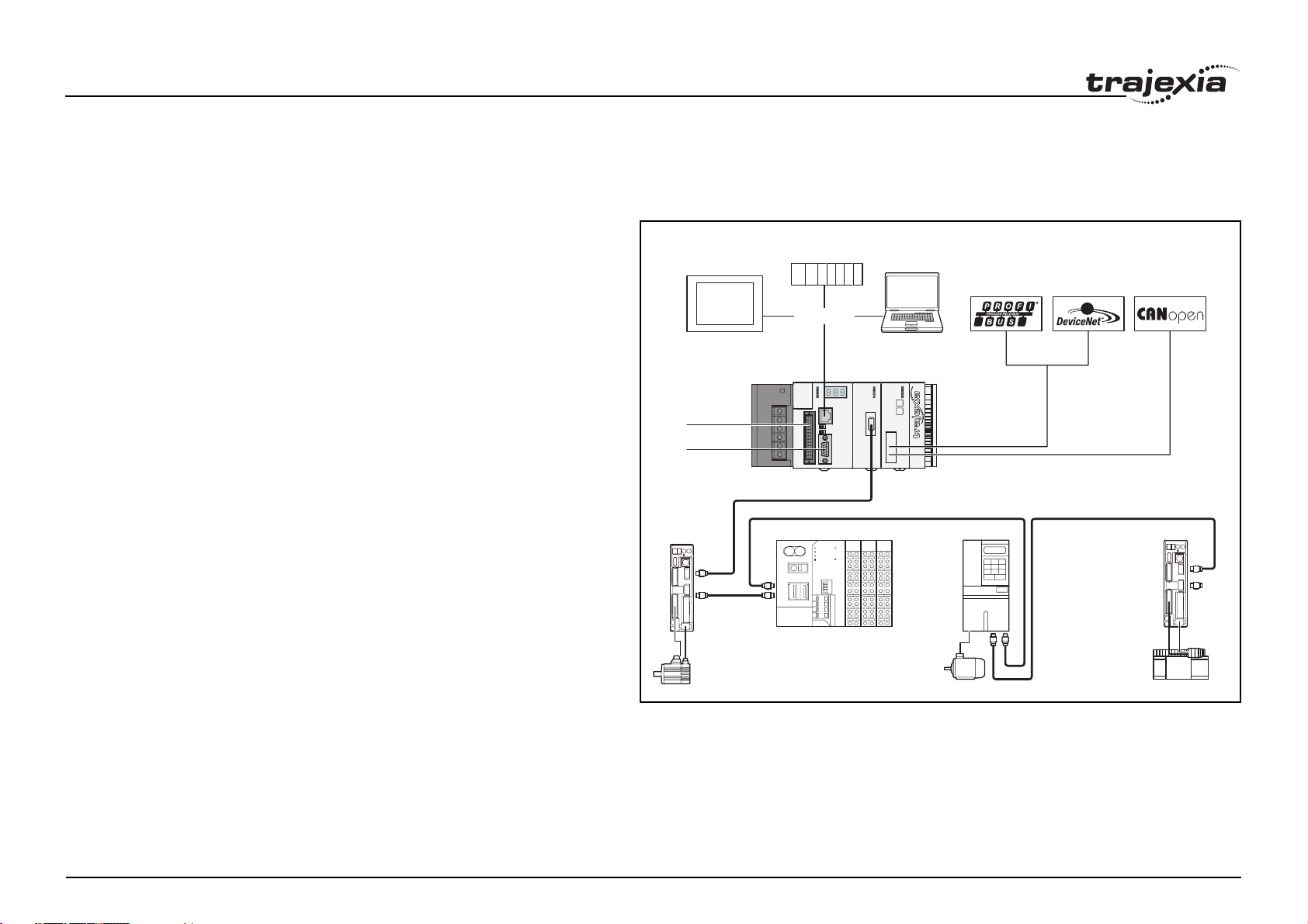
2.1.1 Trajexia hardware
NS-series HMI
Digital I/O
Hostlink
CJ-series PLC CX-one
Ethernet
MECHATROLINK-II
Trajexia Tools
fig. 1
PROFIBUS-DP
Master
DEVICENET
Master
CANopen
Master
The Trajexia hardware is described in the Trajexia Hardware Reference
manual. It is recommend to read the Hardware Reference manual first.
The Trajexia system gives these advantages:
Direct connectivity via Ethernet
Trajexia's built-in Ethernet interface provides direct and fast connectivity to
PCs, PLCs, HMIs and other devices while providing full access to the CPU
Revision 1.0
and to the Drives over a MECHATROLINK-II motion bus. It allows explicit
PROGRAMMING MANUAL 6
Page 13

Trajexia system
messaging over Ethernet and through MECHATROLINK-II to provide full
transparency down to the actuator level, and making remote access
possible.
Revision 1.0
PROGRAMMING MANUAL 7
Page 14

Trajexia system
Keep your know-how safe
By preventing access to the programs in the controller Trajexia guarantees
complete protection and confidentiality for your valuable know-how.
Serial Port and Local I/Os
A serial port provides direct connectivity with any OMRON PLC, HMIs or any
other field device. 16 Inputs and 8 outputs are freely configurable embedded
I/Os in the controller to enable you to tailor Trajexia to your machine design.
MECHATROLINK-II Master
The MECHATROLINK-II master performs control of up to 16 Servo Drives,
Inverters or I/Os while allowing complete transparency across the whole
system.MECHATROLINK-II offers the communication speed and time
accuracy essential to guarantee perfect motion control of Servo Drives. The
motion cycle time is selectable between 0.5 ms, 1 ms or 2 ms.
TJ1-FL02 (Flexible Axis Unit)
The TJ1-FL02 allows full control of two actuators via an analogue output or
pulse train. The module supports the main absolute encoder protocols
allowing the connection of an external encoder to the system.
Drives and Inverters
A wide choice of rotary, linear and direct-drive Servo systems as well as
Inverters are available to fit your needs in compactness, performance and
reliability. The Inverters connected to the MECHATROLINK-II are driven at
the same update cycle time as the Servo Drives.
Remote I/Os
The I/Os on the MECHATROLINK-II motion bus provide for system
expansion while keeping the devices under one motion bus.
PROFIBUS-DP
The PROFIBUS-DP slave allows connectivity to the PROFIBUS network in
Revision 1.0
your machine.
DeviceNet
The DeviceNet slave allows connectivity to the DeviceNet network in your
machine.
CANopen
The CANopen master allows connectivity to the CANopen network in your
machine.
Modbus
Both ModbusRTU via serial and ModbusTCP via Ethernet are supported to
be able to connect to masters supporting the same interface.
2.1.2 This manual
This Programming Manual gives the dedicated information for:
• The description and use of the BASIC commands
• The communication protocols necessary for the Trajexia system
• The use and description of the parts of the Trajexia Studio interface
• Program examples and good programming practices
• Troubleshooting and fault finding.
2.2 Multitasking BASIC programming
The TJ2-MC64 units (Machine Controller Unit) feature a multitasking version
of the BASIC programming language. The motion control language is largely
based upon a tokenised BASIC and the programs are compiled into the
tokenised form prior to their execution.
Multitasking is simple to set up and use and allows very complex machines
to be programmed. Multitasking gives the TJ2-MC64 a significant advantage
over equivalent single task systems. It allows modular applications where
the logically connected processes can be grouped together in the same task
program, thus simplifying the code architecture and design.
The TJ2-MC64 can hold up to 32 programs if memory size permits. Up to 22
programs can be run simultaneously. The execution of the programs is user
controlled using BASIC.
The BASIC commands, functions and parameters presented here can be
found in chapter 3.
PROGRAMMING MANUAL 8
Page 15

Trajexia system
2.3 BASIC programming
The BASIC language consists among others of commands, functions and
parameters. These BASIC statements are the building blocks provided to
control the TJ2-MC64 operation.
Commands are words recognized by the processor that perform a certain
action but do not return a value. For example, PRINT is a recognized word
that will cause the value of the following functions or variables to be printed
on a certain output device.
Functions are words recognized by the processor that perform a certain
action and return a value related to that action. For example, ABS will take
the value of its parameter and return the absolute value of it to be used by
some other function or command. For example ABS(-1) will return the value
1, which can be used by the PRINT command, for example, to generate a
string to be output to a certain device.
Parameters are words recognized by the processor that contain a certain
value. This value can be read and, if not read only, written. Parameters are
used to determine and monitor the behavior of the system. For example,
ACCEL determines the acceleration rate of a movement for a certain axis.
2.3.1 Axis, system and task statements
The commands, functions and parameters apply either to (one of) the axes,
the tasks running or the general system.
Individual axis dependent commands or parameters can also be
programmed to work on a temporary base axis by including the AXIS
function as a modifier in the axis dependent command. A temporary base
axis is effective only for the command or parameter after which AXIS
appears.
Task statements
The task parameters apply to a single task. The task parameters monitor the
task for example for error handling. The PROC modifier allows the user to
access a parameter of a certain task. Without PROC the current task is
assumed. The BASE command (see above) is task specific and can be
used with the PROC modifier.
System statements
These statements govern the overall system features, which are basically all
statements which do not belong to the first two groups.
2.3.2 Memory areas
Three main memory areas can be identified in the Trajexia Motion Controller
Unit:
• I/O memory.
• VR memory.
• TABLE memory.
Axis statements
The motion control commands and the axis parameters apply to one or more
axes. Axis parameters determine and monitor how an axis reacts on
commands given and how it reacts to the outside world. Every axis has a set
of parameters, so that all axes can work independently of each other. The
motion control commands are able to control one or more of the axes
simultaneously, while every axis has its own behavior. The axis parameters
are reset to their default values for each startup.
The commands and parameters work on some base axis or group of axes,
Revision 1.0
specified by the BASE command. The BASE command is used to change
this base axis group and every task has its own group which can be changed
at any time. The default base axis is 0.
PROGRAMMING MANUAL 9
I/O memory
I/O memory is used for holding the status of input and output devices
connected to the Trajexia system. It is divided into two sub-areas: one for
digital I/O memory, and one for analog I/O memory. The digital I/O memory
holds input and output statuses of digital I/O devices. Its capacity is 256 bits
(input points) for input and 256 bits (output points) for outputs. The inputs in
this memory can be accessed using the IN command. The outputs can be
accessed using the OUT command.
The analog I/O memory holds input and output values of analog I/O devices.
Its capacity is 36 input channels and 36 output channels. The analog input
channels can be accessed using the AIN command. The analog output
channels can be accessed using the AOUT command.
Page 16

Trajexia system
VR memory
VR memory is commonly used if some data or value needs to be global,
which means that it is accessible from all programs in the project at the
same time. The size of this memory is 64,000 slots with indexes 0 to 63,999.
A memory slot is addressed using the VR(x) macro where x is index of the
VR memory slot. The VR memory is accessible for reading and writing.
Writing is done by making mathematical assignment using the = command
in the program. The content of this memory is held in the battery powered
RAM memory and is preserved during power off. The VR memory is also
preserved when changing the battery, if this is done quickly.
TABLE memory
TABLE is commonly used if some data or value needs to be global, which
means that it is accessible from all programs in the project at the same time.
Whereas the VR memory is used for similar purposes to define several
global data and values, TABLE memory is used for much bigger amounts of
global data, which also need to be arranged in a certain order. For this
reason, TABLE memory is commonly used for storing TABLE data, motion
profiles, logging data, etc. Some BASIC commands that provide this type
and size of data, for example SCOPE, CAM, CAMBOX etc., require use of
TABLE memory to write their results. The size of this memory is 500,000
slots with indexes 0 to 499,999. The TABLE is accessible for reading and
writing too, but the way it is accessed differs for those two operations. Before
being read, a particular TABLE memory slot needs to be defined and written
first, using the command TABLE(x, value1, value2,…) where x is the index
of the start TABLE memory slot to define, and value1, value2, ... are the
values written into the TABLE memory at indexes x, x+1, ... Once defined
and written, the TABLE memory slot can be read using the TAB LE( x )
command, where x is the index of the TABLE memory slot. An attempt to
read an undefined TABLE memory slot results in an error reported by the
TJ2-MC64. The first 65,536 TABLE memory entries are held in the battery
powered RAM memory and is preserved during power off. This part of the
TABLE memory is also preserved when changing the battery, if this is done
quickly.
Revision 1.0
2.3.3 Data structures and variables
BASIC programs can store numerical data in various types of variables.
Some variables have predefined functions, such as the axis parameters and
system parameters; other variables are available for the programmer to
define as required in programming. The TABLE, global and local variables of
the TJ2-MC64 are explained in this section. Furthermore also the use of
labels will be specified.
TABLE variables
The TABLE is an array structure that contains a series of numbers. These
numbers are used for instance to specify positions in the profile for a CAM or
CAMBOX command. They can also be used to store data for later use, for
example to store the parameters used to define a workpiece to be
processed.
The TABLE is common to all tasks on the TJ2-MC64. This means that the
values written to the TABLE from one task can be read from other tasks.
TABLE values can be written and read using the TABLE command. The
maximum length of the array is 500,000 elements, from TABLE(0) to
TABLE(499999). The TABLE array is initialized up to the highest defined
element.
Global variables
The global variables, defined in VR memory, are common to all tasks on the
TJ2-MC64. This means that if a program running on task 2 sets VR(25) to a
certain value, then any other program running on a different task can read
that same value from VR(25). This is very useful for synchronizing two or
more tasks, but care must be taken to avoid more than one program writing
to the same variable at the same time. The controller has 64,000 global
variables, VR(0) to VR(63999). The variables are read and written using the
VR command.
PROGRAMMING MANUAL 10
Page 17

Trajexia system
/i
Note
The TABLE and VR data can be accessed from the different running tasks. When using either VR or TABLE variables, make sure
to use only one task to write to one particular variable. This to
avoid problems of two program tasks writing unexpectedly to one
variable.
Local variables
Named variables or local variables can be declared in programs and are
local to the task. This means that two or more programs running on different
tasks can use the same variable name, but their values can be different.
Local variables cannot be read from any task except for the one in which
they are declared. Local variables are always cleared when a program is
started. The local variables can be cleared by using either the CLEAR or the
RESET command.
A maximum of 1024 local variables can be declared. Only the first 32
characters of the name are significant. Undefined local variables will return
zero. Local variables cannot be declared on the command line.
Labels
The BASIC programs are executed in descending order through the lines.
Labels can be used to alter this execution flow using the BASIC commands
GOTO and GOSUB. To define a label it must appear as the first statement
on a line and it must be ended by a colon (:). Labels can be character strings
of any length, but only the first 32 characters are significant.
Using variables and labels
Each task has its own local labels and local variables. For example, consider
the two programs shown below:
Revision 1.0
start:
FOR a = 1 to 100
MOVE(a)
WAIT IDLE
NEXT a
GOTO start
start:
a=0
REPEAT
a = a + 1
PRINT a
UNTIL a = 300
GOTO start
These two programs when run simultaneously in different tasks and have
their own version of variable a and label start.
If you need to hold data in common between two or more programs, VR
variables should be used. Or alternatively if the large amount of data is to be
held, the TABLE memory can be used.
To make a program more readable when using a global VR variable, two
approaches can be taken. The first is using a named local variable as a
constant in the VR variable. The local constant variable, however, must be
declared in each program using the global VR variable. Using this approach,
the example below shows how to use VR(3) to hold a length parameter
common for several programs:
/i
start:
GOSUB Initial
VR(length) = x
...
...
Initial:
length = 3
RETURN
start:
GOSUB Initial
MOVE(VR(length))
PRINT(VR(length))
...
Initial:
length = 3
RETURN
The other approach is even more readable and uses the GLOBAL
command to declare the name as a reference to one of the global VR
variables. The name can then be used from within the program containing
the GLOBAL definition and all other programs. Take care that the program
containing the GLOBAL definition must be run before the name is used in
other programs. The best practice is to define global names in the start-up
program. Using this approach, the example above becomes:
PROGRAMMING MANUAL 11
Page 18

Trajexia system
/i
'The declaration in start-up program
GLOBAL length, 3
'In other programs executed after the start-up program
start:
length = x
...
...
start:
MOVE(length)
PRINT(length)
...
Revision 1.0
PROGRAMMING MANUAL 12
Page 19

Trajexia system
2.3.4 Mathematical specifications
Number format
The TJ2-MC64 has two main formats for numeric values: double precision
floating point and double precision integer.
The double precision floating point format is internally a 64 bit value. It has
an 11 bit exponent field, a sign bit and a 52 bit fraction field. Floating point
numbers have a valid range of ±2.2×10
−308
to ±1.8×10
308
.
Integers are essentially floating point numbers with a zero exponent. This
implies that the integers are 53 bits wide. The integer range is therefore
given from -9,007,199,254,740,992 to 9,007,199,254,740,991. Numeric
values outside this range will be floating point.
WARNING
All mathematical calculations are done in floating point format. This
implies that for calculations of/with larger values the results may
have limited accuracy. The user should be aware of this when
developing the motion control application.
Hexadecimal format
The TJ2-MC64 supports assigning and printing hexadecimal values. A
hexadecimal number is input by prefixing the number with the $ character.
Valid range is from 0x0 to 0xFFFFFFFFFFFFF. Example:
>> VR(0)=$FF
>> PRINT VR(0)
255.0000
A value can be printed in hexadecimal by using the HEX function. Negative
values result in the 2’s complement hexadecimal value (53-bit). Valid range
is from −xxx to xxx. Example:
>> TABLE(0,-10,65536)
>> PRINT HEX(TABLE(0)),HEX(TABLE(1))
1FFFFFFFFFFFF6 10000
Revision 1.0
Positioning
For positioning, the TJ2-MC64 will round up if the fractional encoder edge
distance calculated exceeds 0.9. Otherwise the fractional value will be
rounded down. The internal measured position and demanded position of
the axes, represented by the MPOS and DPOS axis parameters, have xxxbit counters.
Floating point comparison
The comparison function considers a small difference between values as
equal to avoid unexpected comparison results. Therefore any two values for
which the difference is less than <EXOO>1.19×10
−6
are considered equal.
Precedence
The precedence of the operators is given below:
1. Unary minus, NOT
2. ^
3. / *
4. MOD
5. + -
6. = <> > >= <= <
7. AND OR XOR
8. Left to right
The best way to ensure the precedence of various operators is through the
use of parentheses.
PROGRAMMING MANUAL 13
Page 20
Trajexia system
2.4 Motion execution
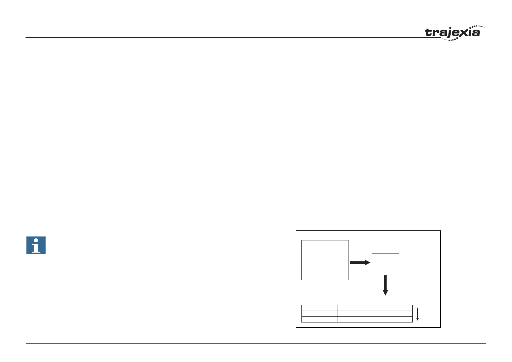
Every task on the TJ2-MC64 has a set of buffers that holds the information
from the motion commands given.
2.4.1 Motion generator
The motion generator has a set of up to 64 motion buffers for each axis.
One buffer called MTYPE, holds the Actual Move, which is the move
currently executing on the axis. The next buffer called NTYPE, holds the
Next Move, which is executed after the Actual Move has finished.
See chapter 2.8 “Motion Buffers” in the Trajexia Hardware Reference
manual for detailed explanation.
The BASIC programs are separate from the motion generator program,
which controls moves for the axes. The motion generator has separate
functions for each axis, so each axis is capable of being programmed with its
own axis parameters (for example speed, acceleration) and moving
independently and simultaneously or they can be linked together using
special commands.
When a move command is being processed, the motion generator waits until
the move is finished and the buffer for the required axis has become empty,
and then loads these buffers with the next move information.
Note
If the task buffers are full, the program execution is paused until
buffers are available again. This also applies to the command line
task and no commands can be given for that period. Trajexia Studio will disconnect in such a case. The PMOVE task parameter will
be set to TRUE when the task buffers are full and will be reset to
FALSE when the task buffers are available again.
Task buffers
Task 1
MOVECIRC(..) AXIS(0)
FORWARD AXIS(1)
Task 2
Task 3
MOVE(..) AXIS(0)
fig. 2
Motion
Generator
Sequencing
Move buffers
Revision 1.0
Axis
Next Move (NTYPE)
Next Move (NTYPE)
012
MOVE (1)
MOVECIRC (4)
FORWARD (10)
MOVECIRC (4)
IDLE (0)
IDLE (0)
Move
Loading
PROGRAMMING MANUAL 14
Page 21

Trajexia system
2.4.2 Sequencing
On each servo cycle interrupt (see section 2.6.2), the motion generator
examines the NTYPE buffers to see if any of them are available. If there are
any available then it checks the task buffers to see if there is a move waiting
to be loaded. If a move can be loaded, then the data for all the specified
axes is loaded from the task buffers into the NTYPE buffers and the
corresponding task buffers are marked as idle. This process is called
sequencing.
2.4.3 Move loading
Once sequencing has been completed, the MTYPE buffers are checked to
see if any moves can be loaded. If the required MTYPE buffers are
available, then the move is loaded from the NTYPE buffers to the MTYPE
buffers and the NTYPE buffers are marked as idle. This process is called
move loading. If there is a valid move in the MTYPE buffers, then it is
processed. When the move has been completed, the MTYPE buffers are
marked as idle.
2.5 Command line interface
The command line interface provides a direct interface for the user to
execute commands and access parameters on the system.
Use the Terminal Window in Trajexia Studio when the TJ2-MC64 is
connected.
The TJ2-MC64 puts the last 10 commands given on the command line in a
buffer. Pressing the Up and Down Cursor Key will cycle through the buffer to
execute the command again.
2.6 BASIC programs
The TJ2-MC64 can store up to 32 programs in memory, provided the
capacity of memory is not exceeded. The TJ2-MC64 supports simple filehandling instructions for managing these program files rather like the DOS
Revision 1.0
filing system on a computer.
The Trajexia Studio software package is used to store and load programs to
and from a computer for archiving, printing and editing. It also has several
controller monitor and debugging facilities.
2.6.1 Managing programs
The Trajexia Studio software package is used to store and load programs to
and from a computer for archiving, printing and editing. It also has several
controller monitor and debugging facilities. For more information please refer
to the Trajexia Studio user manual.
Storing programs
Programs in the TJ2-MC64 are stored automatically in Flash-ROM memory
and therefore do not rely on the battery.
2.6.2 Program execution
The timing of the execution for the different tasks and the refreshing of the I/
O of the TJ2-MC64 revolves around the servo cycle period of the system.
The servo cycle period is determined by the SERVO_PERIOD system
parameter. The TJ2-MC64 will either have a servo cycle period of 0.25, 0.5,
1.0 or 2.0 ms.
I/O refresh
The I/O status of the TJ2-MC64 is refreshed at the beginning of every cycle
time.
• The captured status of the digital inputs is transferred to the IN system
input variable. Note that this is the status captured in the previous servo
cycle.
• The analogue outputs for the speed references are updated.
• The digital outputs are updated conform the status of the OP system
output variable.
• The status of the digital inputs is captured.
PROGRAMMING MANUAL 15
Page 22
Trajexia system
Note that no automatic processing of the I/O signals is taking place, except
for registration. This implies that all actions must be programmed in the
BASIC programs.
Relevant commands
Trajexia Studio provides several ways of executing, pausing and stopping
the programs using buttons on the control panel and the editing windows.
The following commands can be given on the command line to control the
execution.
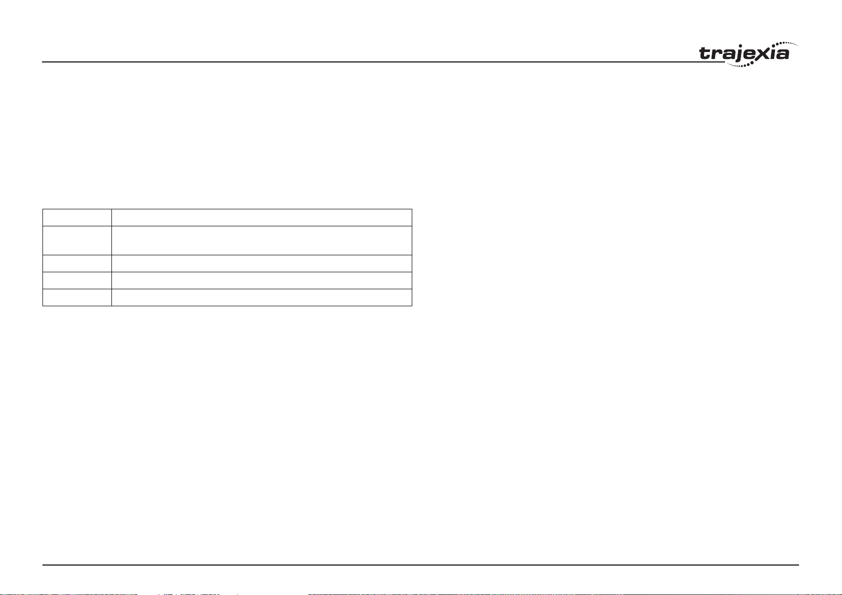
/i
Command Function
RUN Run the current selected program or a specified program, optionally on a
specified task number.
STOP Stop the current selected program or a specified program.
HALT Stop all programs on the system.
PROCESS Displays all running tasks.
The user can explicitly allocate the task priority on which the BASIC program
is expected to run. When a user program is run without explicit task
allocation, it is assigned the highest available task priority.
Setting programs to run at start-up
Programs can be set to run automatically at different priorities when power is
turned on. If required, the computer can be left connected as an operator
interface or may be removed and the programs run stand-alone.
Programs are set in Trajexia Studio to run automatically at start-up by
setting the startup priority with the Priority property in the Properties window.
If you click the ellipsis button in the edit field of this property, the StartUp
Priority window shows. To set the program to run at power up, select the
Run at Power Up check box and select a priority in the list. Possible priority
values are Default or 0 (lowest priority) to 21 (highest priority).The current
status in the controller can be seen using the DIR command.
Revision 1.0
For more information on program control, multitasking and cycle times, refer
to sections 2.2 and 2.3 of the Trajexia Hardware Reference Manual.
PROGRAMMING MANUAL 16
Page 23
BASIC commands
3 BASIC commands
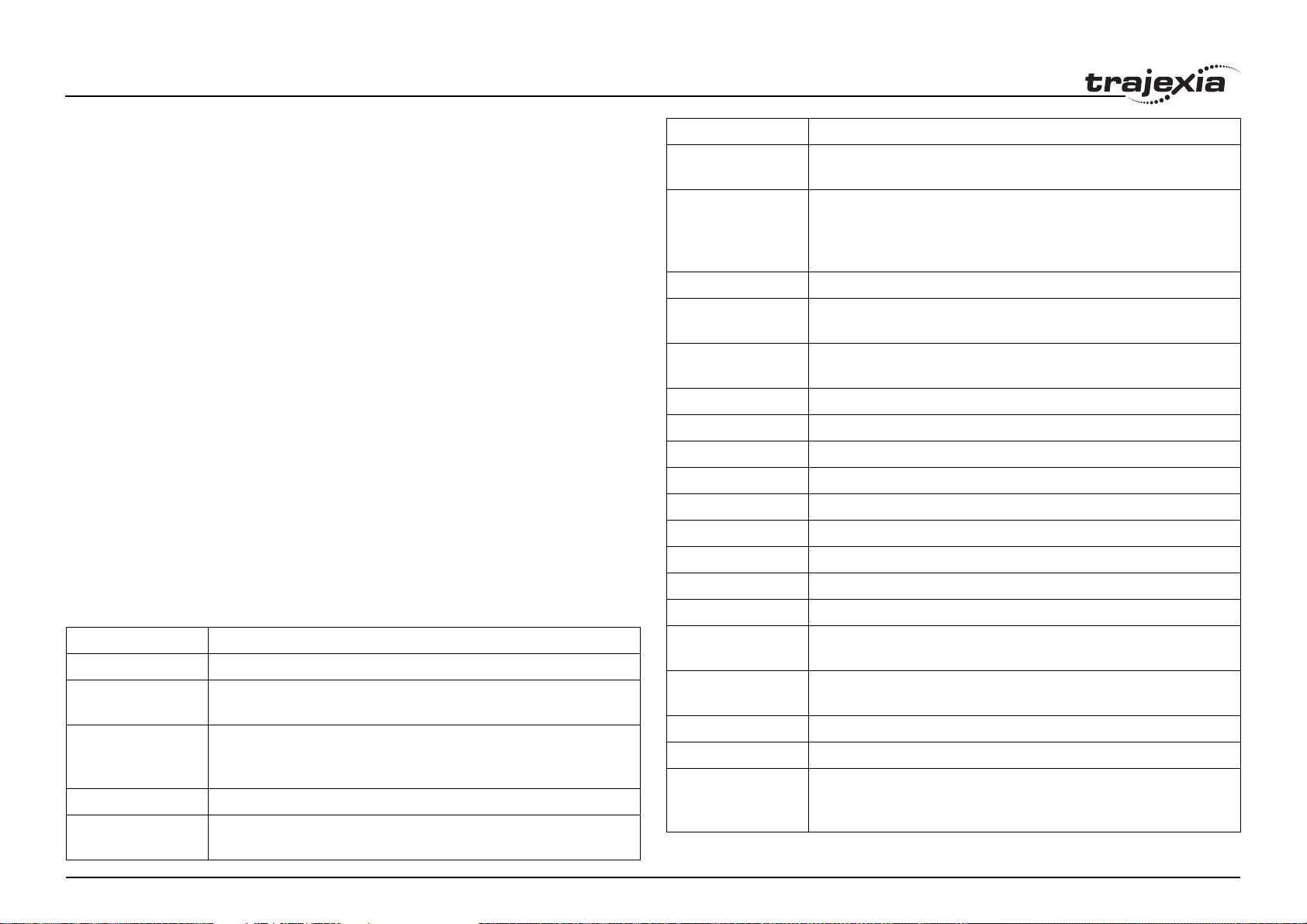
3.1 Categories
This section lists all BASIC commands divided by categories. The categories
are:
• Axis commands.
•Axis parameters.
• Communication commands and parameters.
• Constants.
• I/O commands, functions and parameters.
• Mathematical functions and operations.
• Program commands.
• Program control commands.
• Slot parameters and modifiers.
• System commands and functions.
• System parameters.
• Task commands and parameters.
The lists are quick reference guides only. A complete description of the
commands is given in alphabetical order in the next section.
3.1.1 Axis commands
/i
Name Description
CAM Moves an axis according to values of a movement profile stored in
the TABLE variable array.
CAMBOX Moves an axis according to values of a movement profile stored in
the TABLE variable array. The motion is linked to the measured
motion of another axis to form a continuously variable software gearbox.
CANCEL Cancels the move on an axis.
CONNECT Connects the demand position of an axis to the measured move-
ments of an other axis to produce an electronic gearbox.
DATUM Performs one of 7 origin search sequences to position an axis to an
absolute position or reset a motion error.
DEFPOS Defines the current position as a new absolute position.
DISABLE_GROUP Groups axes together for error disabling.
DRIVE_ALARM Monitors the current alarm.
DRIVE_CLEAR Clears the alarm status of the Servo Drive.
DRIVE_READ Reads the specified parameter of the Servo Drive.
DRIVE_RESET Resets the Servo Drive.
DRIVE_WRITE Writes a specific value to the specified parameter of the Servo Drive.
ENCODER_READ Reads a parameter of the EnDat absolute encoder.
ENCODER_WRITE Writes to a parameter of the EnDat absolute encoder.
Name Description
ACC Changes the ACCEL and DECEL at the same time.
ADD_DAC Sum to the DAC value of one axis to the analogue output of the
base axis.
ADDAX Sets a link to a superimposed axis. All demand position movements
for the superimposed axis will be added to any moves that are currently being executed.
Revision 1.0
BACKLASH Allows the backlash compensation to be loaded.
BASE Used to set the base axis to which the commands and parameters
are applied.
FORWARD Moves an axis continuously forward at the speed set in the SPEED
parameter.
MECHATROLINK Initializes MECHATROLINK-II bus and performs various operations
on MECHATROLINK-II stations connected to the bus.
MHELICAL Interpolates 3 orthogonal axes in a helical move.
MHELICALSP Forced speed version of the MHELICAL command.
MOVE Moves one or more axes at the demand speed, acceleration and
deceleration to the position specified as increment from the current
position.
PROGRAMMING MANUAL 17
Page 24

BASIC commands
Name Description
MOVEABS Moves one or more axes at the demand speed, acceleration and
deceleration to the position specified as absolute position.
MOVEABSSP Forced speed version of the MOVEABS command.
MOVECIRC Interpolates 2 orthogonal axes in a circular arc.
MOVECIRCSP Forced speed version of the MOVECIRC command.
MOVELINK Creates a linear move on the base axis linked via a software gear-
box to the measured position of a link axis.
MOVEMODIFY Changes the absolute end position of the current single-axis linear
move (MOVE or MOVEABS).
MOVESP Forced speed version of the MOVE command.
MOVETANG Performs a Tangential move.
MSPHERICAL Moves a group of three axes along a spherical path.
RAPIDSTOP Cancels the current move on all axes.
REGIST Captures an axis position when a registration input or the Z mark on
the encoder is detected.
REVERSE Moves an axis continuously in reverse at the speed set in the
SPEED parameter.
SPHERE_CENTRE Returns the co-ordinates of the centre point (x, y, z) of the most
recent MSPHERICAL.
STEP_RATIO Sets the ratio for the axis stepper output.
3.1.2 Axis parameters
/i
Name Description
ACCEL Contains the axis acceleration rate.
ADDAX_AXIS Contains the number of the axis to which the base axis is cur-
rently linked to by ADDAX.
ATYPE Contains the axis type.
AXIS_DISPLAY Selects information that are represented by the LEDs on the
front cover of the TJ1-FL02.
AXIS_ENABLE Enables and disables particular axis independently of other axis.
AXISSTATUS Contains the axis status.
BACKLASH_DIST Defines the amount of backlash compensation.
CHANGE_DIR_LAST Defines the change in direction in radians of the last pro-
grammed MOVESP/MOVEABSSP/MOVECIRCSP move of 2 or
more axes.
CLOSE_WIN Defines the end of the window in which a registration mark is
expected.
CLUTCH_RATE Defines the change in connection ratio when using the
CONNECT command.
CORNER_STATE Allows a BASIC program to interact with the move loading proc-
ess to facilitate knife rotation at sharp corners.
CREEP Contains the creep speed.
D_GAIN Contains the derivative control gain.
DAC_SCALE Sets scale and polarity applied to DAC values.
DATUM_IN Contains the input number to be used as the origin input.
DECEL Contains the axis deceleration rate.
DECEL_ANGLE Defines the angle change in radians above which an X-Y sys-
Revision 1.0
DEMAND_EDGES Contains the current value of the DPOS axis parameter in
tem should start to decelerate.
encoder edges.
PROGRAMMING MANUAL 18
Page 25

BASIC commands
Name Description
DPOS Contains the demand position generated by the move com-
mands.
DRIVE_CONTROL Selects data to be monitored using DRIVE_MONITOR for axes
connected via the MECHATROLINK-II bus. For axes connected
via the TJ1-FL02, DRIVE_CONTROL sets outputs of the TJ1FL02.
DRIVE_INPUTS Holds I/O data of the Drive connected to MECHATROLINK-II
bus. Data is updated every servo cycle.
DRIVE_MONITOR Monitors data of the Servo Drive connected to MECHATRO-
LINK-II bus. Data are updated every servo cycle.
DRIVE_STATUS Contains the current status of the Servo Drive.
ENCODER Contains a raw copy of the encoder hardware register.
ENCODER_BITS Sets the number of bits for the absolute encoder connected to
TJ1-FL02.
ENCODER_CONTROL Controls operating mode of the EnDat absolute encoder.
ENCODER_ID Returns the ID value of the absolute encoder connected to TJ1-
FL02.
ENCODER_RATIO Sets scaling value for incoming encoder counts.
ENCODER_STATUS Returns the status of the Tamagawa absolute encoder.
ENCODER_TURNS Returns the multi-turn count of the absolute encoder.
END_DIR_LAST Defines the end direction in radians of the last programmed
forced speed move of 2 or more axes.
ENDMOVE Holds the position of the end of the current move.
ENDMOVE_BUFFER Holds the absolute position at the end of the buffered sequence.
ENDMOVE_SPEED Contains the ramp to exit speed when forced speed moves are
loaded.
ERRORMASK Contains the mask value that determines if MOTION_ERROR
Revision 1.0
FAST_ JOG Contains the input number to be used as the fast jog input.
occurs depending on the axis status.
Name Description
FASTDEC Defines ramp to zero deceleration ratio when an axis limit switch
or position is reached.
FE Contains the Following Error.
FE_LATCH Contains the FE value which caused the axis to put controller in
MOTION_ERROR state.
FE_LIMIT Contains the maximum allowable Following Error.
FE_LIMIT_MODE Defines how FE influences MOTION_ERROR state.
FE_RANGE Contains the Following Error warning range limit.
FHOLD_IN Contains the input number to be used as the feedhold input.
FHSPEED Contains the feedhold speed.
FORCE_SPEED Contains the speed when forced speed moves are loaded.
FS_LIMIT Contains the absolute position of the forward software limit.
FULL_SP_RADIUS Contains the full speed radius in user UNITS.
FWD_IN Contains the input number to be used as a forward limit input.
FWD_JOG Contains the input number to be used as a jog forward input.
I_GAIN Contains the integral control gain.
INVERT_STEP Switches a hardware Inverter into the stepper output circuit.
JOGSPEED Sets the jog speed.
LIMIT_BUFFERED Contains the maximum number of move buffers available in the
controller.
MARK Detects the primary registration event on a registration input.
MARKB Detects the secondary registration event on a registration input.
MERGE Is a software switch that can be used to enable or disable the
merging of consecutive moves.
MOVES_BUFFERED Holds the number of moves being buffered by the axis.
MPOS Is the position of the axis as measured by the encoder.
MSPEED Represents the change in the measured position in the last
servo period.
PROGRAMMING MANUAL 19
Page 26
BASIC commands
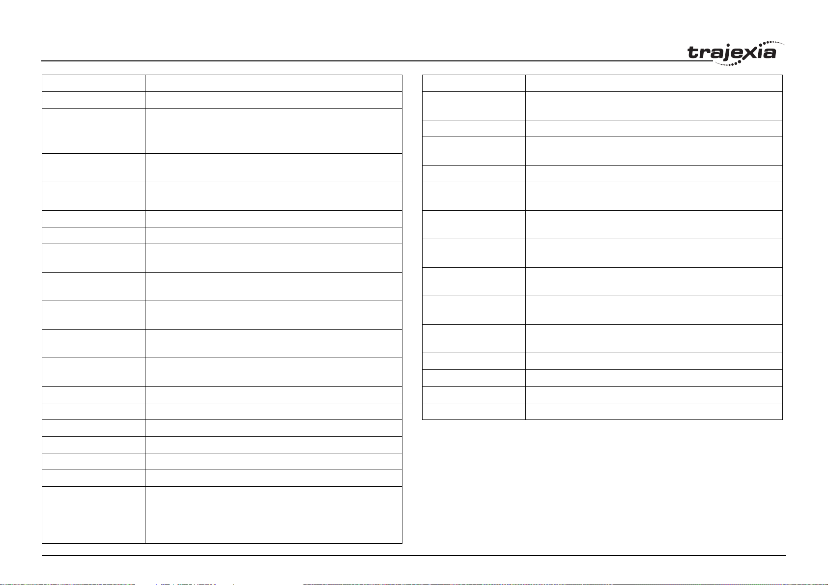
Name Description
MTYPE Contains the type of move currently being executed.
NTYPE Contains the type of the move in the Next Move buffer.
OFFPOS Contains an offset that will be applied to the demand position
without affecting the move in any other way.
OPEN_WIN Defines the beginning of the window in which a registration
mark is expected.
OUTLIMIT Contains the limit that restricts the speed reference output from
the TJ2-MC64.
OV_GAIN Contains the output velocity control gain.
P_GAIN Contains the proportional control gain.
RAISE_ANGLE Defines the angle change in radians above which an X-Y sys-
tem will interact with a BASIC program.
REG_POS Contains the position at which the (primary) registration event
occurred.
REG_POSB Contains the position at which the secondary registration event
occurred.
REGIST_SPEED Contains the speed when the (primary) registration event
occurred.
REGIST_SPEEDB Contains the speed when the secondary registration event
occurred.
Name Description
SERVO Determines whether the axis runs under servo control or open
loop.
SPEED Contains the demand speed in units/s.
SPEED_SIGN Configures the voltage range of the analog speed reference out-
put of the TJ1-FL02.
SRAMP Contains the S-curve factor.
START_DIR_LAST Defines the start direction in radians of the last programmed
forced speed move of 2 or more axes.
STOP_ANGLE Defines the angle change in radians above which an X-Y sys-
tem should decelerate to zero speed.
T_REF Contains the torque reference value which is applied to the
servo motor.
TABLE_POINTER Parmeter to determine which TABLE memory location is cur-
rently being used by the CAM.
TANG_DIRECTION Parameter returns the angle in radians that represents the vec-
tor direction of the interpolated axes.
TRANS_DPOS Contains axis demand position at output of frame transforma-
tion.
UNITS Contains the unit conversion factor.
VECTOR_BUFFERED Holds the total vector length of the buffered moves.
REMAIN Is the distance remaining to the end of the current move.
REP_DIST Contains or sets the repeat distance.
REP_OPTION Controls the application of the REP_DIST axis parameter.
REV_IN Contains the input number to be used as a reverse limit input.
REV_JOG Contains the input number to be used as a jog reverse input.
RS_LIMIT Contains the absolute position of the reverse software limit.
S_REF Contains the speed reference value which is applied when the
Revision 1.0
S_REF_OUT Contains the speed reference value being applied to the Servo
axis is in open loop.
Drive for both open as closed loop.
VFF_GAIN Contains the speed feed forward control gain.
VP_SPEED Contains the speed profile speed.
PROGRAMMING MANUAL 20
Page 27

BASIC commands
3.1.3 Communication commands and parameters
/i
Name Description
FINS_COMMS Sends FINS Read Memory and Write Memory to a designated
FINS server unit.
GET Waits for the arrival of a single character and assigns the ASCII
code of the character to variable.
HLM_COMMAND Executes a specific Host Link command to the Slave.
HLM_READ Reads data from the Host Link Slave to either VR or TABLE var-
iable array.
HLM_STATUS Represents the status of the last Host Link Master command.
HLM_TIMEOUT Defines the Host Link Master timeout time.
HLM_WRITE Writes data to the Host Link Slave from either VR or TABLE var-
iable array.
HLS_NODE Defines the Slave unit number for the Host Link Slave protocol.
INDEVICE Parameter defines the default input device.
INPUT Waits for a string to be received and assigns the numerical value
to variable.
KEY Returns TRUE or FALSE depending on if character is received.
LINPUT Waits for a string and puts it in VR variables.
OUTDEVICE Defines the default output device.
PRINT Outputs a series of characters to a serial port.
SETCOM Sets the serial communications.
Name Description
ON Equal to the numerical value 1.
PI Equal to the numerical value 3.1416.
TRUE Equal to the numerical value -1.
3.1.5 I/O commands, functions and parameters
/i
Name Description
AIN Holds the value of the analog channel.
AOUT Holds the value of the analog channel.
HW_PSWITCH Sets on and off the hardware switch on output 0 of the TJ1-FL02
when predefined positions are reached.
IN Returns the value of digital inputs.
OP Sets one or more outputs or returns the state of the first 24 out-
puts.
PSWITCH Turns on an output when a predefined position is reached, and
turns off the output when a second position is reached.
READ_OP Returns the value of the digital outputs.
3.1.6 Mathematical functions and operands
/i
Name Description
+ (ADDITION) Adds two expressions.
3.1.4 Constants
/i
Name Description
Revision 1.0
FALSE Equal to the numerical value 0.
OFF Equal to the numerical value 0.
- (SUBTRACTION) Subtracts two expressions.
* (MULTIPLICATION) Multiplies two expressions.
/ (DIVISION) Divides two expressions.
^ (POWER) Takes the power of one expression to the other expression.
= (IS EQUAL TO) Checks two expressions to see if they are equal.
= (ASSIGNMENT) Assigns an expression to a variable.
PROGRAMMING MANUAL 21
Page 28
BASIC commands
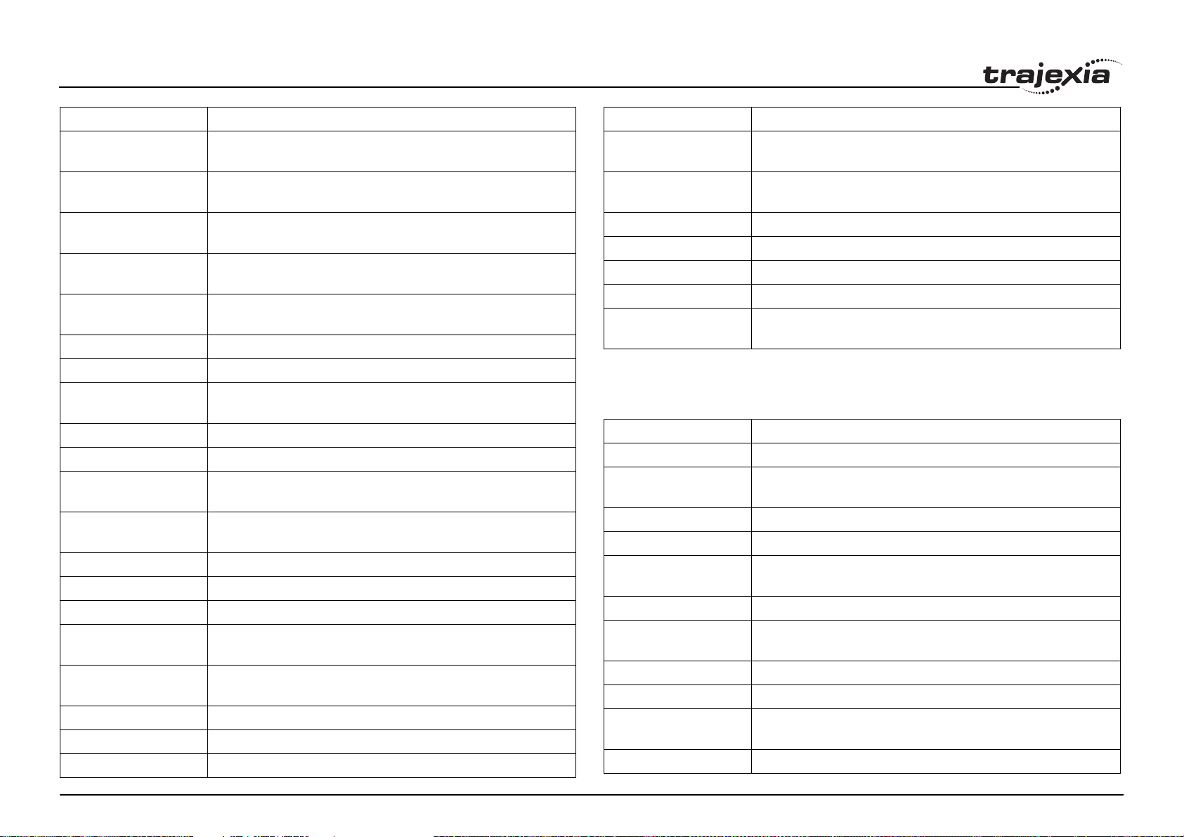
Name Description
<> (IS NOT EQUAL
TO)
> (IS GREATER THAN) Checks two expressions to see if the expression on the left is
>= (IS GREATER
THAN OR EQUAL TO)
< (IS LESS THAN) Checks two expressions to see if the expression on the left is
<= (IS LESS THAN OR
EQUAL TO)
ABS Returns the absolute value of an expression.
ACOS Returns the arc-cosine of an expression.
AND Performs an AND operation on corresponding bits of the integer
ASIN Returns the arc-sine of an expression.
ATAN Returns the arc-tangent of an expression.
ATAN2 Returns the arc-tangent of the non-zero complex number made
B_SPLINE Expands the profile stored in TABLE memory using the B-Spline
COS Returns the cosine of an expression.
EXP Returns the exponential value of an expression.
FRAC Returns the fractional part of an expression.
IEEE_IN Returns floating point number in IEEE format, represented by 4
IEEE_OUT Returns single byte extracted from the floating point number in
INT Returns the integer part of an expression.
Revision 1.0
LN Returns the natural logarithm of an expression.
MOD Returns the modulus of two expressions.
Checks two expressions to see if they are different.
greater than the expression on the right.
Checks two expressions to see if the expression on the left is
greater than or equal to the expression on the right.
less than the expression on the right.
Checks two expressions to see if the expression on the left is
less than or equal to the expression on the right.
parts of two expressions.
by two expressions.
mathematical function.
bytes.
IEEE format.
Name Description
NOT Performs a NOT operation on corresponding bits of the integer
part of the expression.
OR Performs an OR operation between corresponding bits of the
integer parts of two expressions.
SGN Returns the sign of an expression.
SIN Returns the sine of an expression.
SQR Returns the square root of an expression.
TAN Returns the tangent of an expression.
XOR Performs an XOR function between corresponding bits of the
integer parts of two expressions.
3.1.7 Program commands
/i
Name Description
' (COMMENT FIELD) Enables a line not to be executed.
: (STATEMENT
SEPARATOR)
AUTORUN Starts all the programs that have been set to run at start-up.
COMPILE Compiles the current program.
COPY Copies an existing program in the motion controller to a new
DEL Deletes a program from the motion controller.
DIR Displays a list of the programs in the motion controller, their size
LIST Prints the program on the standard output.
NEW Deletes all lines of the program in the motion controller.
PROCESS Returns the running status and task number for each current
RENAME Changes the name of a program in the motion controller.
Enables more statements on one line.
program.
and their RUNTYPE on the standard output.
task.
PROGRAMMING MANUAL 22
Page 29

BASIC commands
Name Description
RUN Executes a program.
RUNTYPE Determines if a program is run at start-up, and which task it is to
run on.
SELECT Specifies the current program.
STEPLINE Executes a single line in a program.
STOP Halts program execution.
TROFF Suspends a trace at the current line and resumes normal pro-
gram execution.
TRON Creates a breakpoint in a program.
3.1.8 Program control commands
/i
Name Description
FOR..TO..STEP..NEXT Loop allows a program segment to be repeated with increasing/
decreasing variable.
GOSUB..RETURN Jumps to a subroutine at the line just after label. The program
execution returns to the next instruction after a RETURN.
GOTO Jumps to the line containing the label.
IF..THEN..ELSE..ENDIF Controls the flow of the program base on the results of the con-
dition.
ON.. GOSUB or ON..
GOTO
REPEAT..UNTIL Loop allows the program segment to be repeated until the con-
WHILE..WEND Loop allows the program segment to be repeated until the con-
Revision 1.0
Enables a conditional jump to one of several labels.
dition becomes TRUE.
dition becomes FALSE .
3.1.9 Slot parameters and modifiers
/i
Name Description
ALL Is a modifier that specifies that all items in the controller are con-
cerned.
COMMSTYPE Contains the type of unit in a controller slot.
FPGA_VERSION Returns the FPGA version of unit with unit_number in a control-
ler system.
SLOT Is a modifier that specifies slot number of unit.
3.1.10 System commands and functions
/i
Name Description
$ (HEXADECIMAL
INPUT)
AXIS Sets the axis for a command, axis parameter read, or assign-
AXIS_OFFSET Defines the axis offset per unit when axes are assigned.
BASICERROR Is used to run a specific routine when an error occurs in a
CAN_CORT Configures the TJ1-CORT for data exchange, or returns the sta-
CLEAR Clears all global variables and the local variables on the current
CLEAR_BIT Clears the specified bit of the specified VR variable.
CLEAR_PARAMS Clears all parameters and variables stored in Flash-ROM to
CONSTANT Declares a constant for use in BASIC program.
CRC16 Calculates the 16 bit CRC of data stored in contiguous TABLE
Assigns a hexadecimal number to a variable.
ment to a particular axis.
BASIC command.
tus of the TJ1-CORT.
task.
their default values.
or VR Memory locations.
PROGRAMMING MANUAL 23
Page 30
BASIC commands
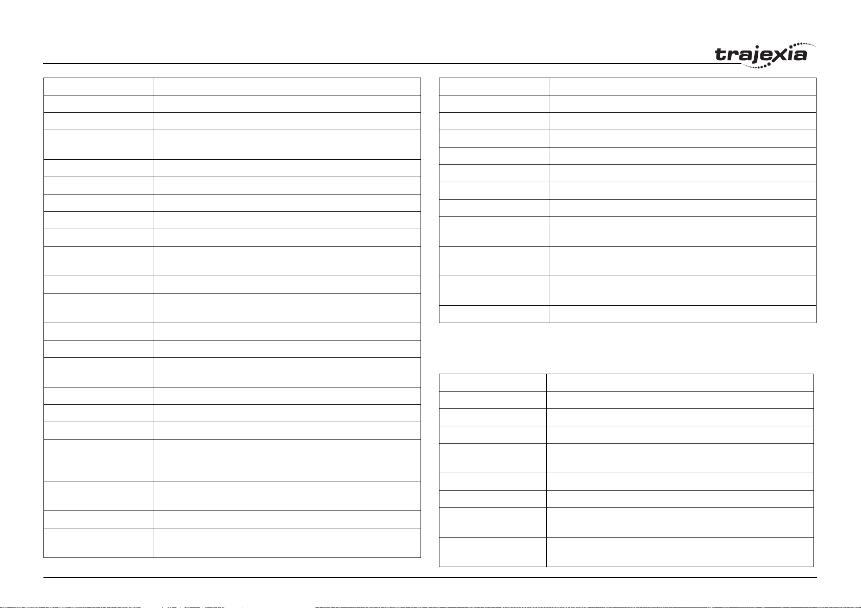
Name Description
DATE$ Prints the current date as a string.
DAY$ Prints the current day as a string
DEVICENET Configures the TJ1-DRT (DeviceNet Slave Unit) for data
exchange, or returns the data exchange status of the TJ1-DRT.
ETHERNET Reads and sets various parameters of TJ2-MC64 Ethernet port.
EX Resets the controller.
FREE Returns the amount of available memory.
GLOBAL Declares a reference to one of VR variables.
HALT Stops execution of all programs currently running.
HEX Used in a print statement to output a number in hexadecimal for-
mat.
INITIALISE Sets all axes and parameters to their default values.
INTEGER_READ Splits a 64 bit variable in 2 32 bit values and copies
these values to 2 other variables.
INVERT_IN Inverts input channels 0 - 31 in the software.
INVERTER_COMMAND Reads I/O and clears alarm of the Inverter.
INVERTER_READ Reads parameter, alarm, speed and torque reference of the
Inverter.
INVERTER_WRITE Writes to parameter, speed and torque reference of the Inverter.
LIST_GLOBAL Shows all GLOBAL and CONSTANT variables.
LOCK Prevents the programs from being viewed or modified.
PROFIBUS Configures the TJ1-PRT (PROFIBUS-DP Slave Unit) to
exchange I/O data with the master and returns the status of the
TJ1-PRT.
READ_BIT Returns the value of the specified bit in the specified VR varia-
ble.
RESET Resets all local variables on a task.
Revision 1.0
SCOPE Programs the system to automatically store up to 4 parameters
every sample period to the TABLE variable array.
Name Description
SET_BIT Sets the specified bit in the specified VR variable to one.
TABLE Writes and reads data to and from the TABLE variable array.
TABLEVALUES Returns list of values from the TABLE memory.
TIME$ Prints the current time as a string.
TRIGGER Starts a previously set SCOPE command.
VR Writes and reads data to and from the global (VR) variables.
VRSTRING Combines VR memory values so they can be printed as a string.
WA Holds program execution for the number of milliseconds speci-
fied.
WAIT IDLE Suspends program execution until the base axis has finished
executing its current move and any buffered move.
WAIT LOADED Suspends program execution until the base axis has no moves
buffered ahead other than the currently executing move.
WAIT UNTIL Repeatedly evaluates the condition until it is TRUE.
3.1.11 System parameters
/i
Name Description
ADDRESS Sets the ModbusRTU multidrop address for the controller
BATTERY_LOW Returns the current status of the battery condition.
CHECKSUM Contains the checksum for the programs in RAM.
COMMSERROR Contains all the communications errors that have occurred since
the last time that it was initialised.
CONTROL Contains the type of TJ2-MC64 in the system.
CORNER_MODE Allows the program to control the cornering action.
D_ZONE_MAX Controls the DAC output in conjunction with the Following Error
value.
D_ZONE_MIN Controls the DAC output in conjunction with the Following Error
value.
PROGRAMMING MANUAL 24
Page 31
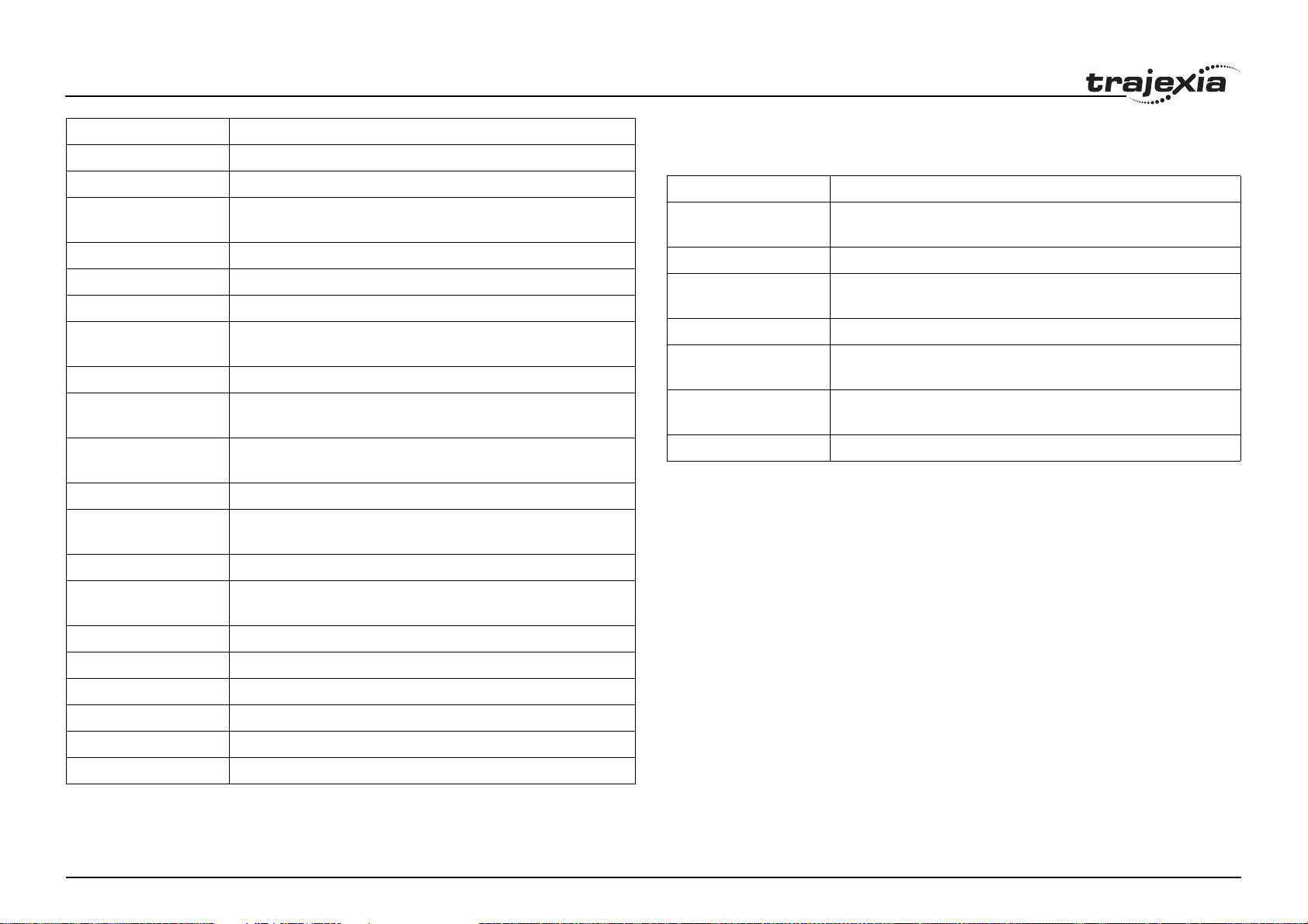
BASIC commands
Name Description
DATE Sets or returns the current date held by the real time clock.
DAY Sets or returns the current day.
DISPLAY Determines I/O channels to be displayed on the front panel
LEDs.
ERROR_AXIS Contains the number of the axis which caused the motion error.
FRAME Specifies operating frame for frame transformations.
LAST_AXIS Contains the number of the last axis processed by the system.
LIMIT_BUFFERED Contains the maximum number of move buffers available in the
system.
MOTION_ERROR Contains an error flag for axis motion errors.
N_ANA_IN Returns the number of analogue inputs connected on the
MECHATROLINK-II bus.
N_ANA_OUT Returns the number of analogue outputs connected on the
MECHATROLINK-II bus.
NEG_OFFSET Applies a negative offset to the DAC signal from the servo loop.
NIO Contains the number of inputs and outputs connected to the
system.
POS_OFFSET Applies a positive offset to the DAC signal from the servo loop.
SCOPE_POS Contains the current TABLE position at which the SCOPE com-
mand is currently storing its first parameter.
3.1.12 Task commands and parameters
/i
Name Description
ERROR_LINE Contains the number of the line which caused the last BASIC
program error.
PMOVE Contains the status of the task buffers.
PROC Lets a process parameter from a particular process to be
accessed.
PROC_STATUS Returns the status of the process specified.
PROCNUMBER Contains the number of the task in which the currently selected
program is running.
RUN_ERROR Contains the number of the last BASIC error that occurred on the
specified task.
TICKS Contains the current count of the task clock pulses.
SERVO_PERIOD Sets the servo cycle period of the TJ2-MC64.
SYSTEM_ERROR Contains the system errors since the last initialization.
TIME Returns the current time held by the real time clock.
TSIZE Returns the size of the currently defined Table.
VERSION Returns the version number of the controller firmware.
WDOG The software switch that enables Servo Drives.
Revision 1.0
PROGRAMMING MANUAL 25
Page 32

BASIC commands
3.2 All BASIC commands
3.2.1 + (Addition)
/i
Type Mathematical function
Syntax expression1 + expression2
Description The operator + adds two expressions.
Arguments • expression1
Any valid BASIC expression.
• expression2
Any valid BASIC expression.
Example result = 4 + 3
Assigns the value 7 to the variable result.
See also N/A
3.2.2 - (Subtraction)
/i
Type Mathematical function
Syntax expression1 - expression2
Description The operator - subtracts expression2 from expression1.
Arguments • expression1
Any valid BASIC expression.
• expression2
Any valid BASIC expression.
Example result = 10 - 2
Assigns the value 8 to the variable result.
See also N/A
3.2.3 * (Multiplication)
/i
Type Mathematical function
Syntax expression1 * expression2
Description The operator * multiplies two expressions.
Arguments • expression1
Any valid BASIC expression.
• expression2
Any valid BASIC expression.
Example result = 3 * 7
Assigns the value 21 to the variable result.
See also N/A
3.2.4 / (Division)
/i
Type Mathematical function
Syntax expression1 / expression2
Description The operator / divides expression1 by expression2.
Arguments • expression1
Any valid BASIC expression.
• expression2
Any valid BASIC expression.
Example result = 11 / 4
Assigns the value 2.75 to the variable result.
See also N/A
Revision 1.0
PROGRAMMING MANUAL 26
Page 33

BASIC commands
3.2.5 ^ (Power)
/i
Type Mathematical function
Syntax expression1 ^ expression2
Description The power operator ^ raises expression1 to the power of expression2.
This operation uses floating point algorithms and may give small deviations for
integer calculations.
Arguments • expression1
Any valid BASIC expression.
• expression2
Any valid BASIC expression.
Example result = 2^5
Assigns the value 32 to the variable result.
See also N/A
3.2.6 = (Is equal to)
/i
Type Mathematical function
Syntax expression1 = expression2
Description The operator = returns TRUE if expression1 is equal to expression2, other-
wise it returns FALSE.
Arguments • expression1
Any valid BASIC expression.
• expression2
Any valid BASIC expression.
Example IF a = 10 THEN GOTO label1
If variable a contains a value equal to 10, program execution continues at
label label1. Otherwise, program execution continues with the next statement.
See also N/A
Revision 1.0
3.2.7 = (Assignment)
/i
Type Mathematical function
Syntax variable = expression
Description The operator = assigns the value of the expression to the variable.
Arguments • variable
A variable name.
• expression
Any valid BASIC expression.
Example var = 18
Assigns the value 18 to the variable var.
See also N/A
3.2.8 <> (Is not equal to)
/i
Type Mathematical function
Syntax expression1 <> expression2
Description The operator <> returns TRUE if expression1 is not equal to expression2,
otherwise it returns FALSE.
Arguments • expression1
Any valid BASIC expression.
• expression2
Any valid BASIC expression.
Example IF a <> 10 THEN GOTO label1
If variable a contains a value not equal to 10, program execution continues at
label label1. Otherwise, program execution continues with the next statement.
See also N/A
PROGRAMMING MANUAL 27
Page 34

BASIC commands
3.2.9 > (Is greater than)
/i
Type Mathematical function
Syntax expression1 > expression2
Description The operator > returns TRUE if expression1 is greater than expression2,
otherwise it returns FALS E .
Arguments • expression1
Any valid BASIC expression.
• expression2
Any valid BASIC expression.
Example IF a > 10 THEN GOTO label1
If variable a contains a value greater than 10, program execution continues at
label label1. Otherwise, program execution continues with the next statement.
See also N/A
3.2.10 >= (Is greater than or equal to)
/i
Type Mathematical function
3.2.11 < (Is less than)
/i
Type Mathematical function
Syntax expression1 < expression2
Description The operator < returns TRUE if expression1 is less than
expression2, otherwise it returns FALSE.
Arguments • expression1
Any valid BASIC expression.
• expression2
Any valid BASIC expression.
Example IF a < 10 THEN GOTO label1
If variable a contains a value less than 10, program execution continues at label label1. Otherwise, program execution continues
with the next statement.
See also N/A
3.2.12 <= (Is less than or equal to)
/i
Type Mathematical function
Syntax expression1 >= expression2
Description The operator >= returns TRUE if expression1 is greater than or equal to
expression2, otherwise it returns FALSE.
Arguments • expression1
Any valid BASIC expression.
• expression2
Any valid BASIC expression.
Example IF a >=10 THEN GOTO label1
If variable a contains a value greater than or equal to 10, program execution
continues at label label1. Otherwise, program execution continues with the
Revision 1.0
See also N/A
next statement.
Syntax expression1 <= expression2
Description The operator <= returns TRUE if expression1 is less than or equal to
expression2, otherwise it returns FALSE.
Arguments • expression1
Any valid BASIC expression.
• expression2
Any valid BASIC expression.
Example IF a <= 10 THEN GOTO label1
If variable a contains a value less than or equal to 10, program execution continues at label label1. Otherwise, program execution continues with the next
statement.
See also N/A
PROGRAMMING MANUAL 28
Page 35

BASIC commands
3.2.13 $ (Hexadecimal input)
/i
Type System command
Syntax $hex_num
Description The $ command makes the number that follows a hexadecimal number.
Arguments • hex_num
A hexadecimal number (consisting of the characters 0 - 9 and A - F).
hex_num ranges from 0 to 1FFFFFFFFFFFFF.
Example >>TABLE(0, $F, $ABCD)
>>print TABLE(0), TABLE(1)
15.0000 43981.0000
See also HEX (PRINT)
3.2.14 ' (Comment field)
/i
Type Program command
Syntax '
Description ' marks all that follows it on a line as comment and not program code. Com-
ment is not executed when the program is run. You can use ' at the beginning
of a line or after a valid statement.
Arguments N/A
Example ' This line is not printed
PRINT "Start"
See also N/A
3.2.15 : (Statement separator)
/i
Type Program command
Syntax :
Description The statement separator : separates multiple BASIC statements on one line.
You can use it on the command line and in programs.
Arguments N/A
Example PRINT "THIS LINE": GET low : PRINT "DOES THREE THINGS"
See also N/A
3.2.16 #
/i
Type Special character
Syntax #
Description The # symbol is used to specify a communications channel to be used for
serial input/output commands.
Note: Communications Channels greater than 3 will only be used when running the Trajexia Studio software.
Arguments N/A
Example PRINT #1, "RS232"
PRINT #2, "RS485"
Example IF KEY #1 THEN GET #1, k
Checks keypad on RS232 port, which represent communication channel 1.
See also N/A
Revision 1.0
PROGRAMMING MANUAL 29
Page 36

BASIC commands
3.2.17 ABS
/i
Type Mathematical function
Syntax ABS(expression)
Description The ABS function returns the absolute value of an expression.
Arguments • expression
Any valid BASIC expression.
Example IF ABS(A) > 100 THEN PRINT "A is outside range -100 ... 100"
See also N/A
3.2.18 ACC
/i
Type Axis command
Syntax ACC(rate)
Description Sets the acceleration and deceleration at the same time.
This command gives a quick method to set both ACCEL and DECEL. Acceleration and deceleration rates are recommended to be set with the ACCEL
and DECEL axis parameters.
Arguments • rate
The acceleration/deceleration rate in units/s
with the UNITS axis parameter.
Example ACC(100)
Sets ACCEL and DECEL to 100 units/s
See also ACCEL, DECEL, UNITS
2
.
2
. You can define the units
3.2.19 ACCEL
/i
Type Axis parameter
Syntax ACCEL = expression
Description The ACCEL axis parameter contains the axis acceleration rate. The rate is
set in units/s
Arguments N/A
Example BASE(0)
ACCEL = 100 ' Set acceleration rate
PRINT "Acceleration rate: "; ACCEL; " mm/s/s"
ACCEL AXIS(2) = 100 ' Sets acceleration rate for axis (2)
See also ACCEL, DECEL, UNITS
2
. The parameter can have any positive value including zero.
3.2.20 ACOS
/i
Type Mathematical function
Syntax ACOS(expression)
Description The ACOS function returns the arc-cosine of the expression. The expression
value must be between -1 and 1. The result in radians is between 0 and PI.
Input values outside the range will return 0.
Arguments • expression
Any valid BASIC expression.
Example >> PRINT ACOS(-1)
3.1416
See also N/A
Revision 1.0
PROGRAMMING MANUAL 30
Page 37
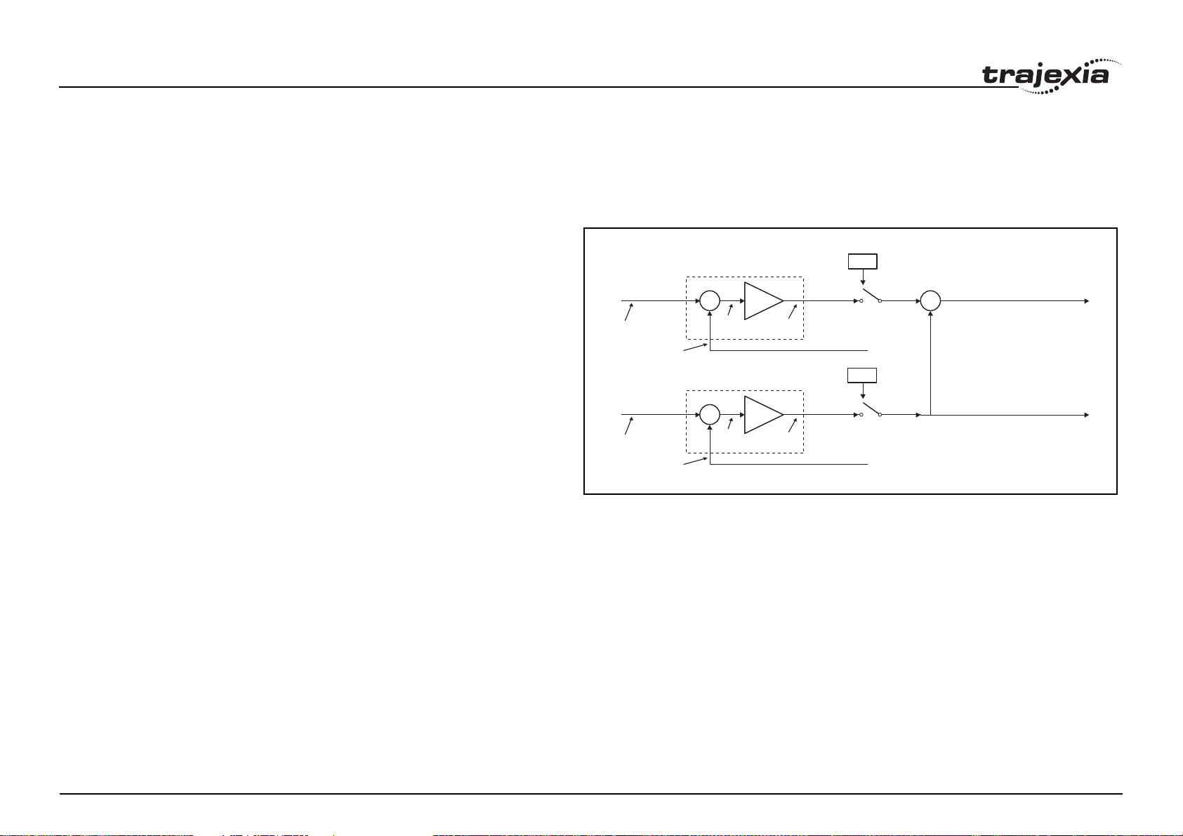
BASIC commands
3.2.21 ADD_DAC
/i
Type Axis command
Syntax ADD_DAC(axis)
fig. 1/i
Description The ADD_DAC command adds the DAC_OUT value of axis to the
DAC_OUT value of the base axis. Use ADD_DAC(-1) to cancel the sum.
ADD_DAC works on the default basis axis (set with BASE) unless AXIS is
used to specify a temporary base axis.
Note:
1. Be aware that the control loop gains for both axes need to be determined
with care. As different encoders with different resolutions are used, the
gains are not identical.
2. Set the OUTLIMIT parameter to the same value for both linked axes.
3. This command has no meaning for a MECHATROLINK-II axis in position
mode (ATYPE=40), because the value of DAC_OUT is ignored.
Arguments • axis
The axis from which to sum the speed reference output to the base axis.
Set the argument to -1 to cancel the link and return to normal operation.
Example No example.
See also AXIS, DAC_OUT, OUTLIMIT
Demanded
position
Demanded
position
Measured
position
Measured
position
AXIS m
Position loop
+
_
AXIS n
Position loop
+
_
Following
error
Following
error
Speed
command
Speed
command
DAC
SERVO = OFF
SERVO = ON
DAC
SERVO = OFF
SERVO = ON
ADD_DAC(n) AXIS(m):
+
DAC_OUT AXIS(m) + DAC_OUT AXIS(n)
+
Final speed reference in AXIS(n) =
Revision 1.0
PROGRAMMING MANUAL 31
Page 38

BASIC commands
3.2.22 ADDAX
/i
Type Axis command
Syntax ADDAX(axis)
Description The ADDAX command is used to superimpose two or more movements to
build up a more complex movement profile.
The ADDAX command takes the demand position changes from the superimposed axis as specified by the axis argument and adds them to any movement running on the axis to which the command is issued. The axis specified
by the parameter can be any axis and does not have to physically exist in the
system.
The ADDAX command therefore allows an axis to perform the moves specified on two axes added together. When the axis parameter is set to OFF on
an axis with an encoder interface the measured position MPOS is copied into
the demanded position DPOS. This allows ADDAX to be used to sum
encoder inputs.
After the ADDAX command has been issued the link between the two axes
remains until broken. Use ADDAX(-1) to cancel the axis link. ADDAX allows
an axis to perform the moves specified for 2 axes added together. Combinations of more than two axes can be made by applying ADDAX to the superimposed axis as well.
ADDAX works on the default basis axis (set with BASE) unless AXIS is used
to specify a temporary base axis.
Note: The ADDAX command sums the movements in encoder edge units.
Arguments • axis
The axis to be set as a superimposed axis. Set the argument to -1 to cancel the link and return to normal operation.
Revision 1.0
PROGRAMMING MANUAL 32
Page 39
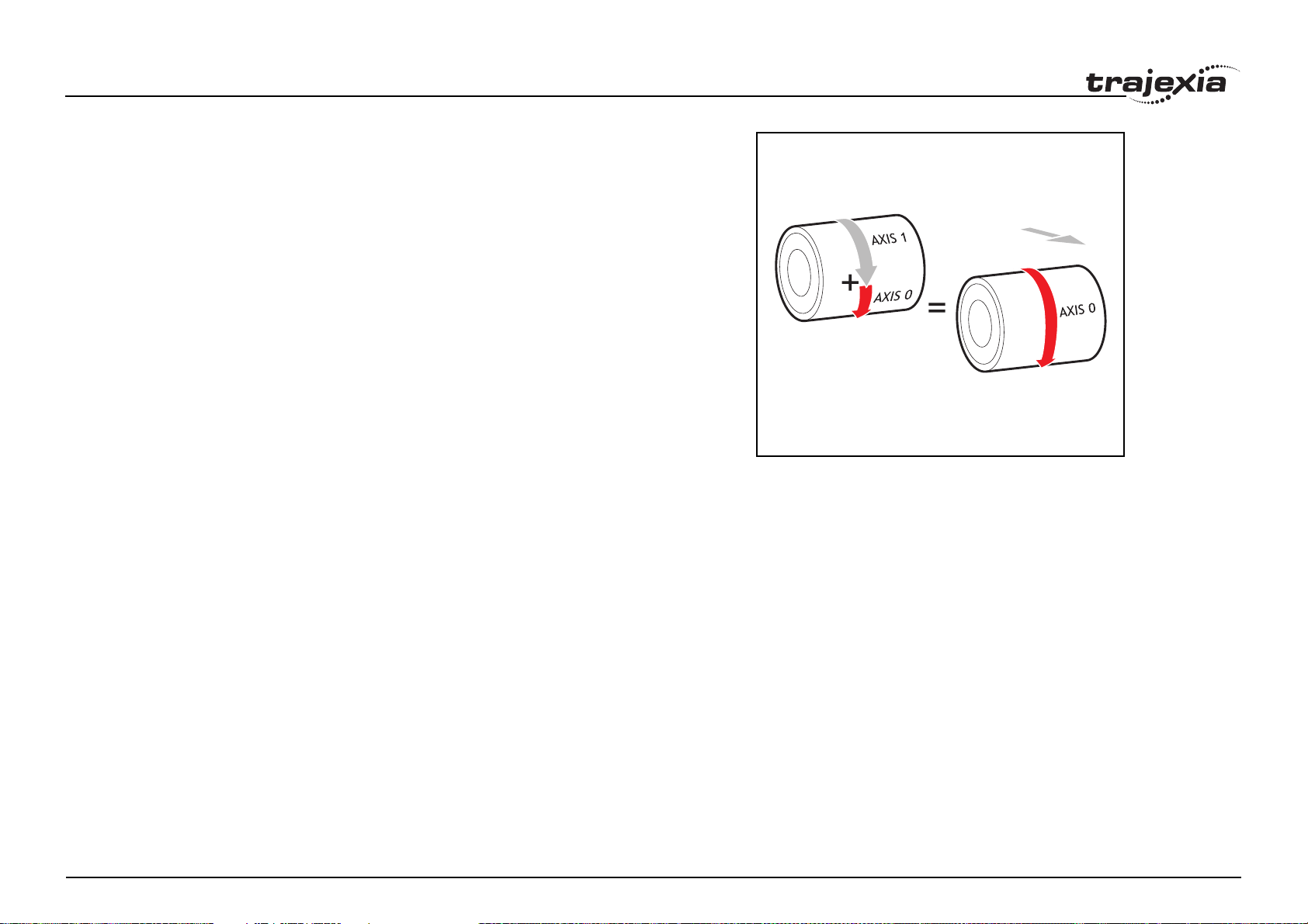
BASIC commands
Example UNITS AXIS(0)=1000
UNITS AXIS(1)=20
' Superimpose axis 1 on axis 0
ADDAX(1) AXIS(0)
MOVE(1) AXIS(0)
MOVE(2) AXIS(1)
'Axis 0 will move 1*1000+2*20=1040 edges
fig. 2/i
Revision 1.0
PROGRAMMING MANUAL 33
Page 40
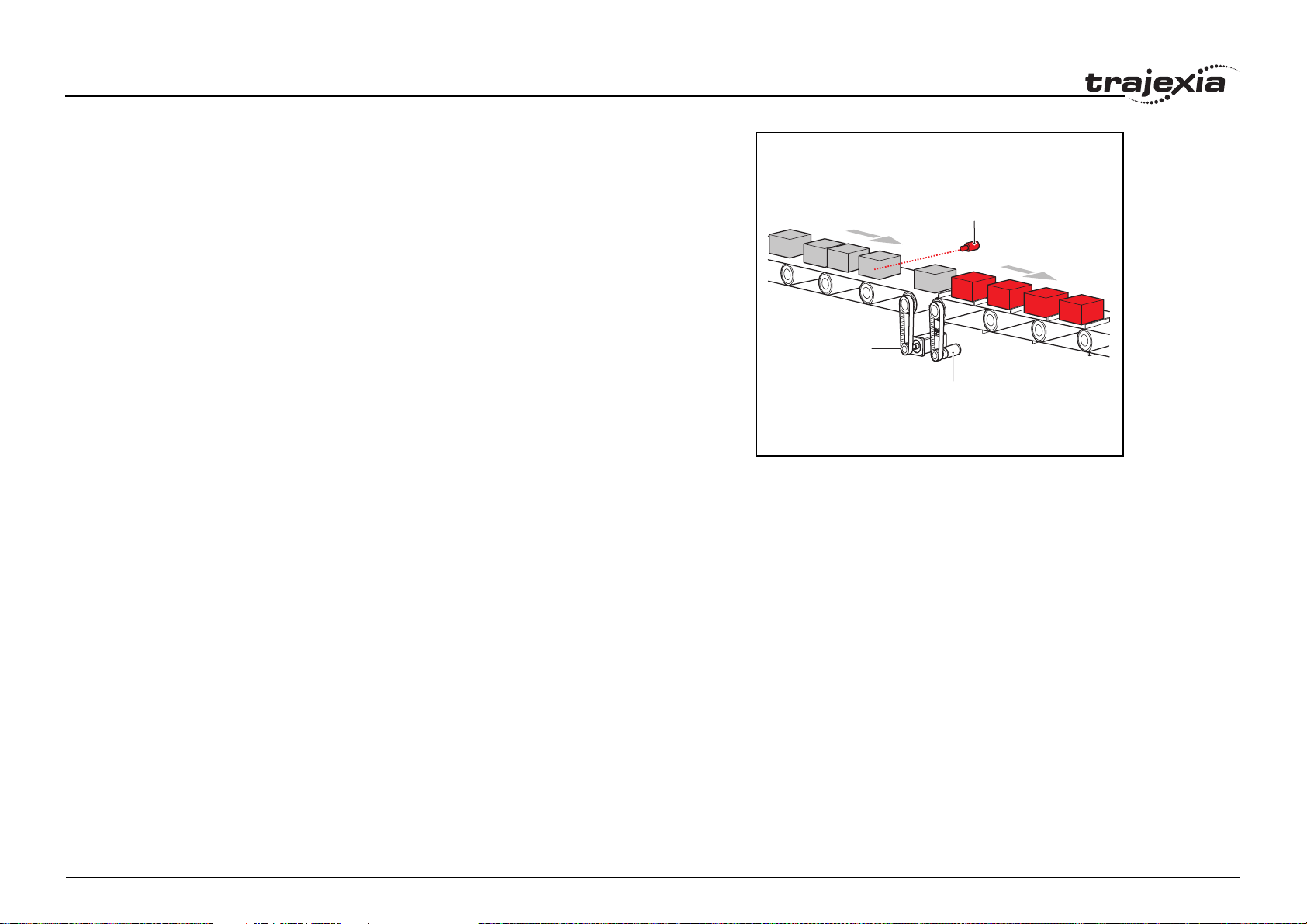
BASIC commands
Example Pieces are placed randomly onto a belt that moves continuously. Further
along the line they are transferred to a second flighted belt. A detection system indicates if a piece is in front of or behind its nominal position, and how
far.
expected=2000 ' sets expected position
BASE(0)
ADDAX(1)
CONNECT(1,2) ' continuous geared connection to flighted belt
REPEAT
GOSUB getoffset ' get offset to apply
MOVE(offset) AXIS(1) ' make correcting move on virtual axis
UNTIL IN(2)=OFF ' repeat until stop signal on input 2
RAPIDSTOP
ADDAX(-1) ' clear ADDAX connection
STOP
getoffset: ' sub routine to register the position of the
' piece and calculate the offset
BASE(0)
REGIST(3)
WAIT UNTIL MARK
seenat=REG_POS
offset=expected-seenat
RETURN
Axis 0 in this example is connected to the encoder of the second conveyor. A
superimposed MOVE on axis 1 is used to apply offsets.
fig. 3/i
R AXIS 0
MOTOR
AXIS 0
ENCODER
AXIS 2
Revision 1.0
PROGRAMMING MANUAL 34
Page 41
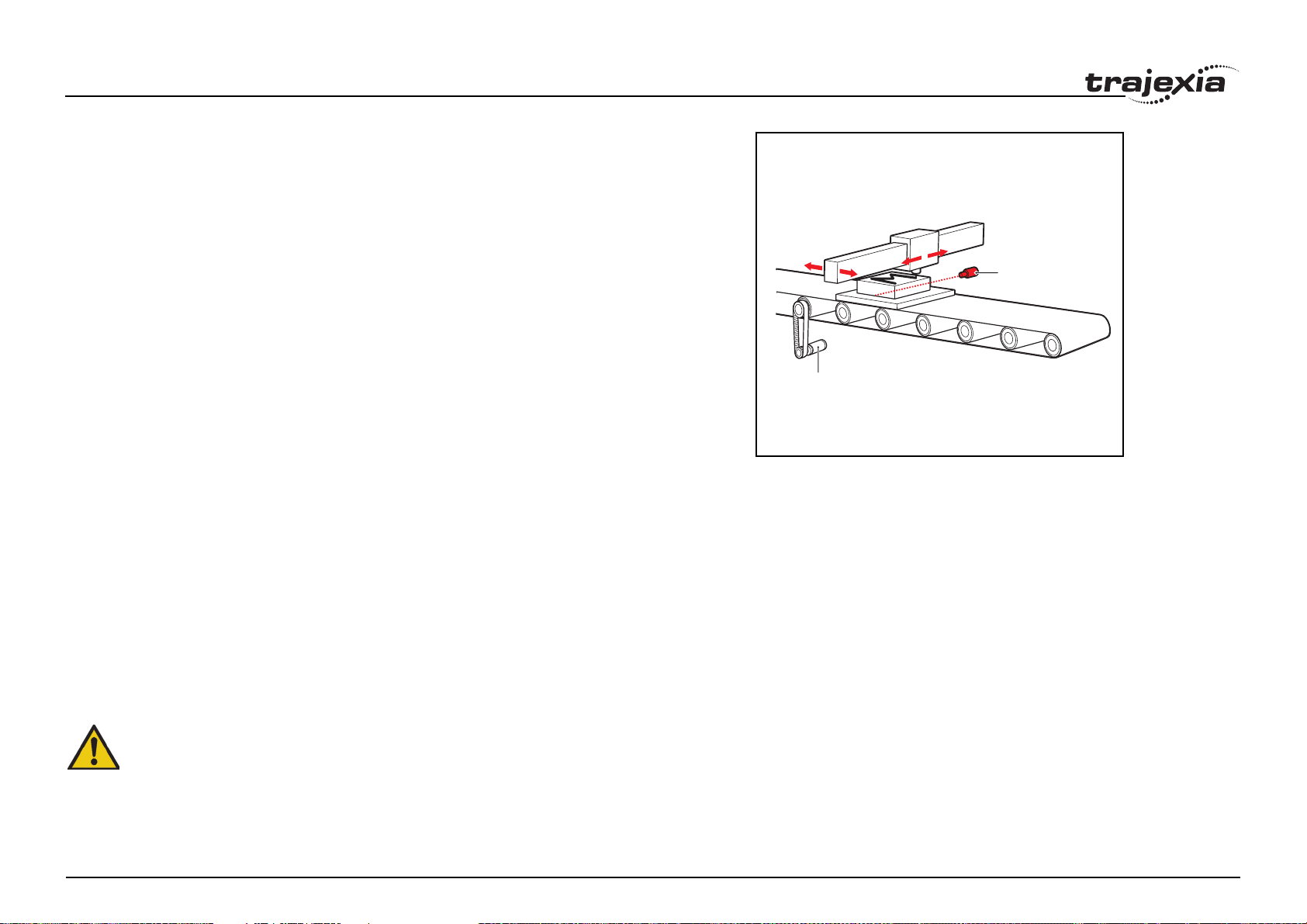
BASIC commands
Example An X-Y marking machine must mark boxes as they move along a conveyor.
Using CONNECT enables the X marking axis to follow the conveyor. A virtual
axis is used to program the marking absolute positions; this is then superimposed onto the X axis using ADDAX.
ATYPE AXIS(3)=0 'set axis 3 as virtual axis
SERVO AXIS(3)=ON
DEFPOS(0) AXIS(3)
ADDAX (3)AXIS(0) 'connect axis 3 requirement to axis 0
WHILE IN(2)=ON
REGIST(3) 'registration input detects a box on the conveyor
WAIT UNTIL MARK OR IN(2)=OFF
IF MARK THEN
CONNECT(1,2) AXIS(0)'connect axis 0 to the moving belt
BASE(3,1) 'set the drawing motion to axis 3 and 1
'Draw the M
MOVEABS(1200,0)'move A > B
MOVEABS(600,1500)'move B > C
MOVEABS(1200,3000)' move C > D
MOVEABS(0,0)'move D > E
WAIT IDLE
BASE(0)
CANCEL 'stop axis 0 from folowing the belt
WAIT IDLE
MOVEABS(0) 'move axis 0 to home position
ENDIF
WEND
CANCEL
AXIS 0
ENCODER
AXIS 2
fig. 4/i
AXIS 1
R AXIS 0
See also ADDAX_AXIS, AXIS, OUTLIMIT
WARNING
Beware that giving several ADDAX commands in a system can
create a dangerous loop when for instance one axis is linked to
Revision 1.0
PROGRAMMING MANUAL 35
another and vice versa. This may cause instability in the system.
Page 42

BASIC commands
3.2.23 ADDAX_AXIS
/i
Type Axis parameter (read-only)
Syntax ADDAX_AXIS
Description The ADDAX_AXIS axis parameter returns the number of the axis to which
the base axis is currently linked to by ADDAX. If the base axis in not linked to
any other axis, the ADDAX_AXIS parameter returns -1.
Arguments N/A
Example >> BASE(0)
>> ADDAX(2)
>> PRINT ADDAX_AXIS
2.0000
>> ADDAX(-1)
>> PRINT ADDAX_AXIS
-1.0000
See also ADDAX, AXIS
3.2.24 ADDRESS
/i
Type SYSTEM parameter
Syntax ADDRESS
Description Sets the RS-232 and RS485/422 ModbusRTU multidrop address for the con-
troller. This parameter should be in the range of [1 – 32].
Arguments N/A
Example ADDRESS = 5
See also SETCOM
Syntax AIN(analogue_chan)
Description The AIN reads a value from an analogue input. Analogue input channels are
provided by connecting GRT1-ML2 Slice Coupler, or JEPMC-AN2900 modules on the MECHATROLINK-II bus.
Arguments analogue_chan.
Analogue input channel number 0.31
Example MOVE(-5000)
REPEAT
a=AIN(1)
IF a<0 THEN a=0
SPEED=a*0.25
UNTIL MTYPE=0
The speed of a production line is governed by the rate at which material is fed
onto it. The material feed is via a lazy loop arrangement which is fitted with an
ultra-sonic height sensing device. The output of the ultra-sonic sensor is in
the range 0V to 4V where the output is at 4V when the loop is at its longest.
Note: The analogue input value is checked to ensure it is above zero even
though it always should be positive. This is to allow for any noise on the
incoming signal which could make the value negative and cause an error
because a negative speed is not valid for any move type except FORWARD
or REVERSE.
See also N/A
3.2.26 ALL
/i
Type Slot modifier
Syntax ALL
Description The ALL modifier is used with the commands DEL and NEW. It indicates that
these commands are applied to all items in the directory structure of the controller.
3.2.25 AIN
Revision 1.0
/i
Type I/O command
Arguments N/A
Example DEL ALL
This deletes all programs and the TABLE memory of the controller.
PROGRAMMING MANUAL 36
Page 43

BASIC commands
Example HALT
NEW ALL
STORE
This creates the memory of the controller.
See also DEL, NEW.
3.2.27 AND
/i
Type Mathematical operation
Syntax expression1 AND expression2
Description The AND operator performs the logical AND function on the corresponding
bits of the integer parts of two valid BASIC expressions.
The logical AND function between two bits is defined as follows:
0 AND 0 = 0
0 AND 1 = 0
1 AND 0 = 0
1 AND 1 = 1
Arguments • expression1
Any valid BASIC expression.
• expression2
Any valid BASIC expression.
Example VR(0) = 10 AND (2.1*9)
The parentheses are evaluated first, but only the integer part of the result, 18,
is used for the AND operation. Therefore, this expression is equivalent to the
following:
VR(0) = 10 AND 18
The AND is a bit operator and so the binary action is as follows:
01010 AND 10010 = 00010
Therefore, VR(0) will contain the value 2.
Example IF MPOS AXIS(0) > 0 AND MPOS AXIS(1) > 0 THEN GOTO cycle1
If measured positions MPOS of both axis 1 and axis 2 are greater than zero,
Revision 1.0
program execution continues at label cycle1. Otherwise, program execution
continues with the next statement.
3.2.28 AOUT
/i
Type I/O command
Syntax AOUT(analogue_chan)
Description The AOUT command sets the output value of the analogue output channels
that are provided by connecting GRT1-ML2 Slice Coupler or JEPMC-AN2910
modules on the MECHATROLINK-II bus. The range of the value set is [32000, 32000] for full output range. The output range depends on the analogue unit used and can be one of the following: [-10V, 10V], [0V, 10V] or [0V,
5V] for voltage and [0mA, 20mA] or [4mA, 20mA] for current output.
Arguments • analogue_chan.
Analogue output channel number 0.31
Example No example.
See also N/A
3.2.29 ASIN
/i
Type Mathematical function
Syntax ASIN(expression)
Description The ASIN function returns the arc-sine of the argument. The argument must
have a value between -1 and 1. The result in radians is between -PI/2 and PI/
2. Input values outside this range return 0.
Arguments • expression
Any valid BASIC expression.
Example >> PRINT ASIN(-1)
-1.5708
See also N/A
See also N/A
PROGRAMMING MANUAL 37
Page 44
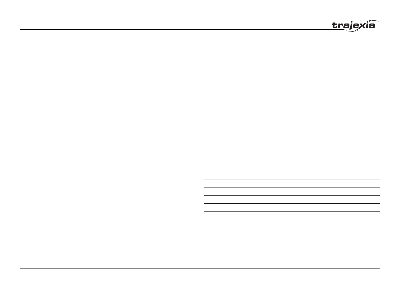
BASIC commands
3.2.30 ATAN
/i
Type Mathematical function
Syntax ATAN(expression)
Description The ATAN function returns the arc-tangent of the argument. expression can
have any value. The result is in radians and is between -PI/2 and PI/2.
Arguments • expression
Any valid BASIC expression.
Example >> PRINT ATAN(1)
0.7854
See also N/A
3.2.31 ATAN2
/i
Type Mathematical function
Syntax ATAN2(expression1, expression2)
Description The ATAN2 function returns the arc-tangent of the non-zero complex number
(expression1, expression2), which is equivalent to the angle between a
point with coordinate (expression1, expression2) and the x-axis. If
expression2 >= 0, the result is equal to the value of ATAN(expression1 /
expression2). The result in radians will be between -PI and PI.
Arguments • expression1
Any valid BASIC expression.
• expression2
Any valid BASIC expression.
Example >> PRINT ATAN2(0,1)
0.0000
See also N/A
Revision 1.0
3.2.32 ATYPE
/i
Type Axis parameter
Syntax ATYPE = value
Description The ATYPE axis parameter indicates the axis type for the axis. The valid val-
ues depend on TJ1 module the Servo Drive controlling the axis is connected
to. See the table below.
/i
AXIS type ATYPE value Applicable TJ1 unit
Virtual 0 All
MECHATROLINK-II Position 40 TJ1-ML__
(MECHATROLINK-II Master Unit)
MECHATROLINK-II Speed 41 TJ1-ML__
MECHATROLINK-II Torque 42 TJ1-ML__
Flexible axis Stepper Out 43 TJ1-FL02
Flexible axis Servo 44 TJ1-FL02
Flexible axis Encoder Out 45 TJ1-FL02
Flexible axis Absolute Tamagawa 46 TJ1-FL02
Flexible axis Absolute EnDat 47 TJ1-FL02
Flexible axis Absolute SSI 48 TJ1-FL02
MECHATROLINK-II Inverter 49 TJ1-ML__
Flexible axis Stepper In 60 TJ1-FL02
/i
The ATYPE parameters are set by the system at start-up. For axes controlled
by the Servo Drives connected to the system via MECHATROLINK-II bus, the
default ATYPE value is 40 (MECHATROLINK-II Position). For axes controlled
by the Servo Drives connected to the system via the TJ1-FL02, the default
ATYPE value is 44 (Flexible Axis Servo).
Arguments N/A
PROGRAMMING MANUAL 38
Page 45
BASIC commands
Example ATYPE AXIS(1) = 45
This command will set axis 1 as Flexible axis encoder output axis.
See also AXIS
3.2.33 AUTORUN
/i
Type Program command
Syntax AUTORUN
Description The AUTORUN command starts all the programs that have been set to run at
start-up.
Note: This command should only be used on the Command Line Terminal.
Arguments N/A
Example No example.
See also RUNTYPE
3.2.34 AXIS
/i
Type System command
Syntax AXIS(axis_number)
Description The AXIS modifier sets the axis for a single motion command or a single axis
parameter read/write to a particular axis. AXIS is effective only for the command or axis parameter operation. If it is required to change the axis used to
a particular axis in every subsequent command, use the BASE command
instead.
Arguments • axis_number
Any valid BASIC expression specifying the axis number.
Example BASE(0)
Revision 1.0
Example MOVE(300) AXIS(0)
PRINT VP_SPEED AXIS(2)
See also BASE
3.2.35 AXIS_DISPLAY
/i
Type Axis parameter
Syntax AXIS_DISPLAY = value
Description The AXIS_DISPLAY axis parameter enables different data to be displayed by
the LEDs on the front cover of the TJ1-FL02 unit. LEDs affected by this
parameter setting are two yellow LEDs showing axis status. The default value
of this parameter on start-up for all axes is 0. The valid values are shown in
the table below.
/i
AXIS_DISPLAY value 0 1 2 3
A0 REG 0 AUX IN OUT 0 ENCODER A
A1 REG 1 ENCODER Z
B0 REG 0 AUX IN OUT 0 ENCODER A
B1 REG 1 ENCODER Z OUT 1 ENCODER B
1. In case of incremental encoder, it reflects the status of the Z-input.
In case of absolute encoder, it reflects the status of the clock output.
/i
Arguments N/A
Example AXIS_DISPLAY AXIS(2) = 2
This command will display status of the outputs OUT 0 and OUT 1 allocated
to axis 2.
See also N/A
1
OUT 1 ENCODER B
Example REP_DIST AXIS(1) = 100
PROGRAMMING MANUAL 39
Page 46
BASIC commands
3.2.36 AXIS_ENABLE
/i
Type Axis parameter
Syntax AXIS_ENABLE = ON/OFF
Description The AXIS_ENABLE axis parameter is used to enable or disable particular
axis independently of others. This parameter can be set ON or OFF for each
axis individually. The default value on start-up is ON for all axes. The axis will
be enabled if both AXIS_ENABLE for that axis is ON and WDOG is on. For
MECHATROLINK-II axes setting AXIS_ENABLE to OFF will disable Servo
Drive output to the motor. For Flexible axis Servo axis setting AXIS_ENABLE
to OFF will force both voltage outputs to 0. For Flexible axis Stepper Out and
Encoder Out axes, setting AXIS_ENABLE to OFF will block pulses generation on the outputs.
Arguments N/A
Example AXIS_ENABLE AXIS(3) = OFF
This command will disable axis 3 independently of other axes in the system.
See also AXIS, DISABLE_GROUP
3.2.37 AXIS_OFFSET
/i
Typ e Sys tem parameter
Syntax AXIS_OFFSET [SLOT(unit_number)] = offset_value
Description Provides control over the position of axes (on a per unit basis) when they are
assigned at system start-up. The offsets are stored in Flash-ROM of the TJ2MC64 and will only become active after the next start-up. The offset specified
will be added to the node address of a MECHATROLINK-II Servo Drive or will
be used as a starting point to search for an unused axis in case of Flexible
axes.
Revision 1.0
Arguments • unit_number
Unit numbers are 0 to 6, with 0 being the unit immediately to the right of
the TJ2-MC64.
• offset_value
Offset applied during axis number assignment for axes connected to the
unit.
Example AXIS_OFFSET SLOT(1)=16
Axes connected to unit in slot 1 will be assigned from axis 16 upwards.
See also SLOT
WARNING
When using multiple TJ1-ML__ units, do not swap the MECHATROLINK-cables. This can result in different axis allocation. This
can result in serious injury and/or significant damage.
3.2.38 AXISSTATUS
/i
Type Axis parameter (read-only)
Syntax AXISSTATUS
Description The AXISSTATUS axis parameter contains the axis status and is used for the
motion error handling of the controller. The axis status consists of status bits,
which definitions are shown in the table below.
/i
Bit
number
0- 1-
1 Following error warning range 2 w
2 Servo Drive communication error 4 a
3 Servo Drive alarm 8 m
4 in forward limit 16 f
Description Value Character (as used in
Trajexia Studio)
5In reverse limit 32r
PROGRAMMING MANUAL 40
Page 47
BASIC commands
Bit
number
6 Datuming 64 d
7 Feed hold input 128 h
8 Following error exceeds limit 256 e
9 In forward software limit 512 x
10 In reverse software limit 1024 y
11 Cancelling move 2048 c
12 Encoder out overspeed 4096 o
/i
Arguments N/A
Example IF (AXISSTATUS AND 16)>0 THEN PRINT "In forward limit"
See also AXIS, ERRORMASK
Description Value Character (as used in
Trajexia Studio)
3.2.39 B_SPLINE
/i
Type Mathematical function
Arguments • type
Reserved for future expansion. Always set this to 1.
• data_in
Location in the TABLE where the source profile is stored.
• number_in
Number of points in the source profile.
• data_out
Location in the TABLE where the expanded profile will be stored.
• expansion_ratio
The expansion ratio, i.e., if the source profile is 99 points and
expansion_ratio is set to 10 the resulting profile will be 1000 point
((number_in+1) * expansion_ratio).
Example BASE(1)
B_SPLINE(1, 0, 9, 200, 10)
This command expands a 10 point profile in TABLE locations 0 to 9 to a larger
100 points profile starting at TABLE location 200.
See also N/A
Syntax B_SPLINE(type, data_in, number_in, data_out, expansion_ratio)
Description Expands an existing profile stored in the TABLE using the B-Spline mathemat-
ical function. The expansion factor is configurable and the B_SPLINE stores
expanded profile to another area in the TABLE.
This is ideally used where the source CAM profile is too course and needs to
be extrapolated into a greater number of points.
Revision 1.0
PROGRAMMING MANUAL 41
Page 48

BASIC commands
3.2.40 BACKLASH
/i
Type Axis command
Syntax BACKLASH(ON/OFF, distance, speed, accel)
Description The BACKLASH command allows the parameters for the backlash compen-
sation to be loaded. The backlash compensation is achieved as follows:
• An offset move is applied when the motor demand is in one direction.
• The offset move is reversed when the motor demand is in the opposite
direction.
These moves are superimposed on the command axis movements.
The backlash compensation is applied after a change in the direction of the
DPOS parameter. The backlash compensation can be seen in the
TRANS_DPOS parameter, which is equal to DPOS + backlash compensa-
tion.
Arguments • ON/OFF
Either ON or OFF.
• distance
The offset distance, expressed in user units.
• speed
The speed of the compensation move, expressed in user units.
• accel
The acceleration or deceleration rate of the compensation move,
expressed in user units.
Example BACKLASH(ON,0.5,10,50) AXIS(0)
BACKLASH(ON,0.4,8,50) AXIS(1)
This applies backlash compensation on axes 0 and 1.
3.2.41 BACKLASH_DIST
/i
Type Axis parameter
Syntax BACKLASH_DIST
Description BACKLASH_DIST is the amount of backlash compensation that is applied to
the axis when BACKLASH = ON.
Arguments N/A
Example IF BACKLASH_DIST>100 THEN
OP (10, ON) ' show that backlash compensation reached this value
ELSE
OP (10, OFF)
END IF
See also BACKLASH
3.2.42 BASE
/i
Type Axis command
Syntax BASE
BASE(axis_1 [ ,axis_2 [ , axis_3 [ , axis_4 [ , axis_...]]]])
BA
BA(axis_1 [ ,axis_2 [ , axis_3 [ , axis_4 [ , axis_...]]]])
See also DPOS, TRANS_DPOS.
Revision 1.0
PROGRAMMING MANUAL 42
Page 49

BASIC commands
Description The BASE command is used to set the default base axis or to set a specified
axis sequence group. All subsequent motion commands and axis parameters
will apply to the base axis or the specified axis group unless the AXIS command is used to specify a temporary base axis. The base axis or axis group is
effective until it is changed again with BASE.
Each BASIC process can have its own axis group and each program can set
its own axis group independently. Use the PROC modifier to access the
parameters for a certain task.
The BASE order grouping can be set by explicitly assigning the order of axes.
This order is used for interpolation purposes in multi-axes linear and circular
moves. The default for the base axis group is (0,1,2 ... 62,63) at start-up or
when a program starts running on a task. The BASE command without any
arguments returns the current base order grouping.
Note: If the BASE command does not specify all the axes, the BASE com-
mand will “fill in” the remaining values automatically. Firstly it will fill in any
remaining axes above the last declared value, then it will fill in any remaining
axes in sequence.
So BASE(2,6,10) sets the internal array of 64 axes to:
2,6,10,11,12,13,14,15 ... ,61,62,63,0,1,3,4,5,7,8,9.
Note: The BASE command without any arguments should only be used on
the Command Line Terminal.
Arguments The command can take up to 64 arguments.
• axis_i
The number of the axis set as the base axis and any subsequent axes in
the group order for multi-axis moves.
Example BASE(1)
UNITS = 2000 ' Set unit conversion factor for axis 1
SPEED = 100 ' Set speed for axis 1
ACCEL = 5000 ' Set acceleration rate for axis 1
BASE(2)
UNITS = 2000 ' Set unit conversion factor for axis 2
SPEED = 125 ' Set speed for axis 2
ACCEL = 10000 ' Set acceleration rate for axis 2
It is possible to program each axis with its own speed, acceleration and other
Revision 1.0
parameters.
Example BASE(0)
MOVE(100,-23.1,1250)
In this example, axes 0, 1 and 2 will move to the specified positions at the
interpolated speed and acceleration set for axis 0. BASE(0) sets the base
axis to axis 0, which determines the three axes used by MOVE and the speed
and acceleration rate.
Example >> BASE
(0,2,1)
On the command line the base group order can be shown by typing BASE.
Example >> RUN "PROGRAM", 3
>> BASE PROC(3)
(0,2,1)
Use the PROC modifier to show the base group order of a certain task.
Example >> BASE(2)
>> PRINT BASE
2.0000
Printing BASE will return the current selected base axis.
See also AXIS
3.2.43 BASICERROR
/i
Type System command
Syntax BASICERROR
Description The BASICERROR command can be used to run a routine when a run-time
error occurs in a program. BASICERROR can only be used as part of an ON
... GOSUB or ON ... GOTO command. This command is required to be executed once in the BASIC program. If several commands are used only the
one executed last is effective.
Arguments N/A
PROGRAMMING MANUAL 43
Page 50

BASIC commands
Example ON BASICERROR GOTO error_routine
...
no_error = 1
STOP
error_routine:
IF no_error = 0 THEN
PRINT "The error "; RUN_ERROR[0];
PRINT " occurred in line "; ERROR_LINE[0]
ENDIF
STOP
If an error occurs in a BASIC program in this example, the error routine will be
executed.
The IF statement is present to prevent the program going into error routine
when it is stopped normally.
See also ERROR_LINE, ON, RUN_ERROR.
3.2.44 BATTERY_LOW
/i
Type System parameter (read-only)
Syntax BATTERY_LOW
Description This parameter returns the current state of the battery condition. If
BATTERY_LOW=ON then the battery needs to be changed. If
BATTERY_LOW=OFF then battery condition is ok.
Arguments N/A
Example No example.
See also N/A
Arguments • program_name
The name of the program from which you want to remove all break
points.
Example BREAK_RESET "simpletest"
Will remove all break points from program simpletest.
See also N/A
3.2.46 CAM
/i
Type Axis command
Syntax CAM(start_point, end_point, table_multiplier, distance)
Description The CAM command is used to generate movement of an axis following a
position profile which is stored in the TABLE variable array. The TABLE values are absolute positions relative to the starting point and are specified in
encoder edges. The TABLE array is specified with the TABLE command.
The movement can be defined with any number of points from 3 to the maximum table size available (500000). The TJ2-MC64 moves continuously
between the values in the TABLE to allow a number of points to define a
smooth profile. Two or more CAM commands can be executed simultaneously using the same or overlapping values in the TABLE array. The TABLE
profile is traversed once.
The distance argument together with the SPEED and ACCEL parameters
determine the speed moving through the TABLE array. Note that in order to
follow the CAM profile exactly the ACCEL parameter of the axis must be at
least 1000 times larger than the SPEED parameter.
CAM works on the default basis axis (set with BASE) unless AXIS is used to
specify a temporary base axis.
3.2.45 BREAK_RESET
/i
Type System command
Revision 1.0
Syntax BREAK_RESET "program_name"
Description Used by Trajexia Studio to remove all break points from the specified pro-
gram.
PROGRAMMING MANUAL 44
Page 51

BASIC commands
Arguments • start_point
The address of the first element in the TABLE array to be used.
Being able to specify the start point allows the TABLE array to hold more
than one profile and/or other information.
• end_point
The address of the end element in the TABLE array.
• table_multiplier
The Table multiplier value used to scale the values stored in the TABLE.
As the Table values are specified in encoder edges, use this argument to
set the values for instance to the unit conversion factor (set by UNITS
parameter).
• distance
A factor given in user units that controls the speed of movement through
the Table. The time taken to execute CAM depends on the current axis
speed and this distance. For example, assume the system is being programmed in mm and the speed is set to 10 mm/s and the acceleration
sufficiently high. If a distance of 100 mm is specified, CAM will take 10
seconds to execute.
The SPEED parameter in the base axis allows modification of the speed
of movement when using the CAM move.
Note: When the CAM command is executing, the ENDMOVE parameter is
set to the end of the previous move.
Revision 1.0
PROGRAMMING MANUAL 45
Page 52
BASIC commands
Example Motion is required to follow the POSITION equation:
t(x) = x*25 + 10000(1-cos(x)), where x is in degrees. This example table provides a simple oscillation superimposed with a constant speed. To load the
table and cycle it continuously the program would be:
FOR deg=0 TO 360 STEP 20 'loop to fill in the table
rad = deg * 2 * PI/360 'convert degrees to radians
x = deg * 25 + 10000 * (1-COS(rad))
TABLE(deg/20,x) 'place value of x in table
NEXT deg
WHILE IN(2)=ON 'repeat cam motion while input 2 is on
CAM(0,18,1,200)
WAIT IDLE
WEND
/i
TABLE position Degree Value
100
2 20 1103
3 40 3340
fig. 5/i
4 60 6500
5 80 10263
6 100 14236
7 120 18000
8 140 21160
9 160 23396
10 180 24500
11 200 24396
12 220 23160
13 240 21000
Revision 1.0
14 260 18236
15 280 15263
PROGRAMMING MANUAL 46
Page 53
BASIC commands
TABLE position Degree Value
16 300 12500
17 320 10340
18 340 9103
19 360 9000
Revision 1.0
PROGRAMMING MANUAL 47
Page 54
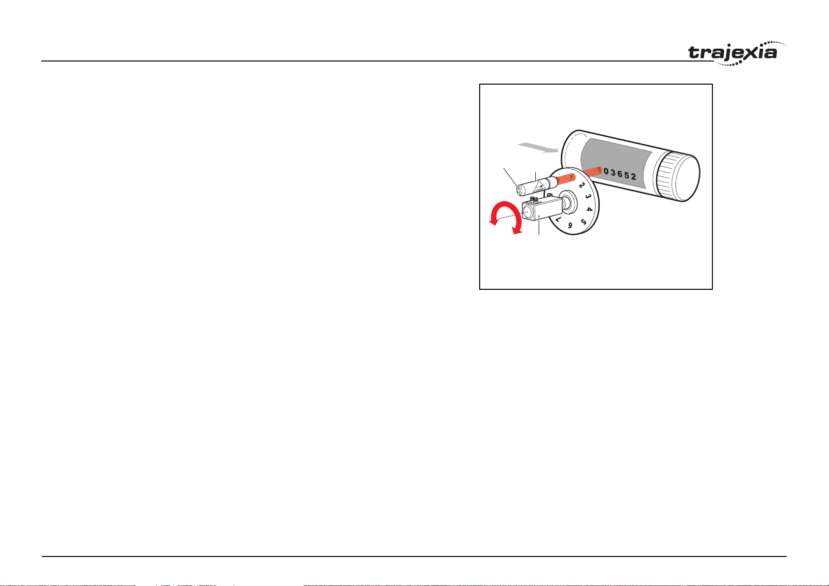
BASIC commands
Example A masked wheel is used to create a stencil for a laser to shine through for use
in a printing system for the ten numerical digits. The required digits are transmitted through port 1 serial port to the controller as ASCII text.
The encoder used has 4000 edges per revolution and so must move 400
between each position. The cam table goes from 0 to 1, which means that the
CAM multiplier needs to be a multiple of 400 to move between the positions.
The wheel is required to move to the pre-set positions every 0.25 seconds.
The speed is set to 10000 edges/second, and we want the profile to be complete in 0.25 seconds. So multiplying the axis speed by the required completion time (10000 x 0.25) gives the distance parameter equals 2500.
GOSUB profile_gen
WHILE IN(2)=ON
WAIT UNTIL KEY#1 'Waits for character on port 1
GET#1,k
IF k>47 AND k<58 THEN 'check for valid ASCII character
position=(k-48)*400 'convert to absolute position
multiplier=position-offset 'calculate relative movement
'check if it is shorter to move in reverse direction
IF multiplier>2000 THEN
multiplier=multiplier-4000
ELSEIF multiplier<-2000 THEN
multiplier=multiplier+4000
ENDIF
CAM(0,200,multiplier,2500) 'set the CAM movment
WAIT IDLE
OP(15,ON) 'trigger the laser flash
WA(20)
OP(15,OFF)
offset=(k-48)*400 'calculates current absolute position
ENDIF
WEND
profile_gen:
num_p=201
scale=1.0
Revision 1.0
FOR p=0 TO num_p-1
TABLE(p,((-SIN(PI*2*p/num_p)/(PI*2))+p/num_p)*scale)
NEXT p
RETURN
OP(15)
TRIGGER
fig. 6/i
LASER
MOTOR
PROGRAMMING MANUAL 48
Page 55

BASIC commands
Example A suction pick and place system must vary its speed depending on the load
carried. The mechanism has a load cell which inputs to the controller on the
analogue channel (AIN).
The move profile is fixed, but the time taken to complete this move must be
varied depending on the AIN. The AIN value varies from 100 to 800, which
must result in a move time of 1 to 8 seconds. If the speed is set to 10000 units
per second and the required time is 1 to 8 seconds, then the distance parameter must range from 10000 to 80000. (distance = speed x time).
The return trip can be completed in 0.5 seconds and so the distance value of
5000 is fixed for the return movement. The Multiplier is set to -1 to reverse the
motion.
GOSUB profile_gen 'loads the cam profile into the table
SPEED=10000:ACCEL=SPEED*1000:DECEL=SPEED*1000
WHILE IN(2)=ON
OP(15,ON) 'turn on suction
load=AIN(0) 'capture load value
distance = 100*load 'calculate the distance parameter
CAM(0,200,50,distance) 'move 50mm forward in time calculated
WAIT IDLE
OP(15,OFF) 'turn off suction
WA(100)
CAM(0,200,-50,5000) 'move back to pick up position
WEND
profile_gen:
num_p=201
scale=400 'set scale so that multiplier is in mm
FOR p=0 TO num_p-1
TABLE(p,((-SIN(PI*2*p/num_p)/(PI*2))+p/num_p)*scale)
NEXT p
RETURN
See also ACCEL, AXIS, CAMBOX, SPEED, TAB LE.
Revision 1.0
PROGRAMMING MANUAL 49
Page 56

BASIC commands
3.2.47 CAMBOX
/i
Type Axis command
Syntax CAMBOX(start_point, end_point, table_multiplier, link_distance,
link_axis [ , link_option [ , link_position ]])
Description The CAMBOX command is used to generate movement of an axis following a
position profile in the TABLE variable array. The motion is linked to the measured motion of another axis to form a continuously variable software gearbox.
The TABLE values are absolute position relative to the starting point and are
specified in encoder edges.
The TABLE array is specified with the TABLE command. The movement can
be defined with any number of points from 3 to the maximum table size available (500000). Being able to specify the start point allows the TABLE array to
be used to hold more than one profile and/or other information. The TJ2MC64 moves continuously between the values in the TABLE to allow a
number of points to define a smooth profile. Two or more CAMBOX com-
mands can be executed simultaneously using the same or overlapping values
in the TABLE array.
Note that CAMBOX command allows traversing the TABLE backwards as
well as forwards depending on the Master axis direction.
The link_option argument can be used to specify different options to start the
command and to specify a continuous CAM. For example, if the link_option
is set to 4 then the CAMBOX operates like a "physical" CAM.
CAMBOX works on the default basis axis (set with BASE) unless AXIS is
used to specify a temporary base axis.
Note: While CAMBOX is being executed, the ENDMOVE parameter will be
set to the end of the previous move. The REMAIN axis parameter will hold the
remainder of the distance on the link axis.
Revision 1.0
PROGRAMMING MANUAL 50
Page 57
BASIC commands
Arguments • start_point
The address of the first element in the TABLE array to be used.
• end_point
The address of the end element in the TABLE array.
• table_multiplier
The Table multiplier value used to scale the values stored in the TABLE.
As the TABLE values are specified in encoder edges, use this argument
to set the values for instance to the unit conversion factor (set by UNITS
parameter).
• link_distance
The distance in user units the link axis must move to complete the specified output movement. The link distance must be specified as a positive
distance.
• link_axis
The axis to link to.
• link_option
See the table below.
/i
link_option value Description
1 Link starts when registration event occurs on link axis.
2 Link starts at an absolute position on link axis (see link_position).
4 CAMBOX repeats automatically and bidirectionally. This option is can-
celled by setting bit 1 of REP_OPTION parameter (REP_OPTION =
REP_OPTION OR 2).
5 Combination of options 1 and 4.
6 Combination of options 2 and 4.
/i
• link_position
The absolute position where CAMBOX will start when link_option is set
to 2.
Note: When the CAMBOX command is executing, the ENDMOVE
Revision 1.0
parameter is set to the end of the previous move. The REMAIN axis
parameter holds the remainder of the distance on the link axis.
PROGRAMMING MANUAL 51
Page 58
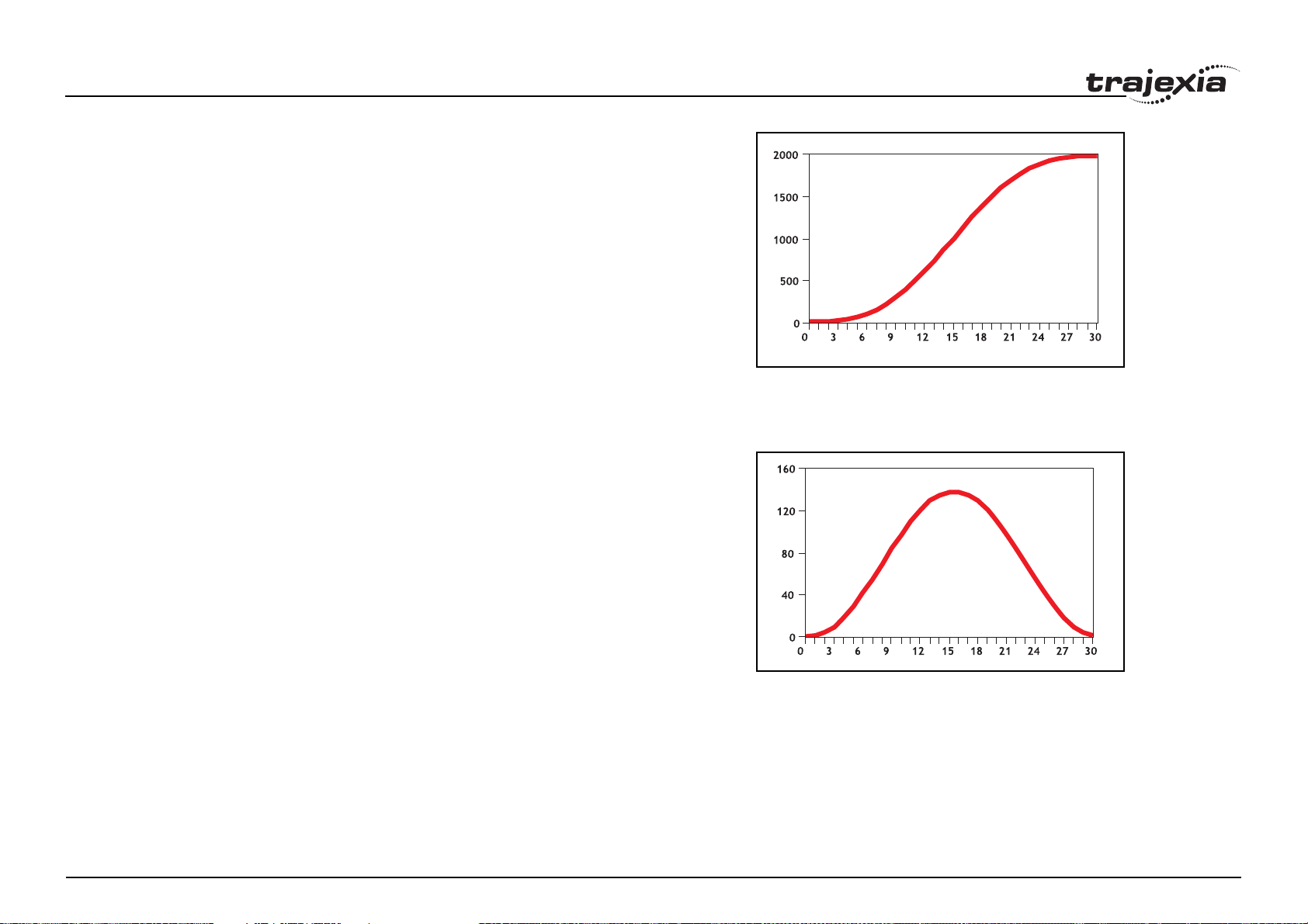
BASIC commands
Example ' Subroutine to generate a SIN shape speed profile
' Uses: p is loop counter
' num_p is number of points stored in tables pos 0..num_p
' scale is distance travelled scale factor
profile_gen:
num_p=30
scale=2000
FOR p=0 TO num_p
TABLE(p,((-SIN(PI*2*p/num_p)/(PI*2))+p/num_p)*scale)
NEXT p
RETURN
This graph plots TABLE contents against table array position. This corresponds to motor POSITION against link POSITION when called using
CAMBOX. The SPEED of the motor will correspond to the derivative of the
position curve above.
fig. 7/i
fig. 8
Revision 1.0
PROGRAMMING MANUAL 52
Page 59
BASIC commands
Example A pair of rollers feeds plastic film into a machine. The feed is synchronised to
a master encoder and is activated when the master reaches a position held in
the variable start. This example uses the table points 0...30 generated in the
example above:
start=1000
FORWARD AXIS(1)
WHILE IN(2)=OFF
CAMBOX(0,30,800,80,15,2,start)
WA(10)
WAIT UNTIL MTYPE=0 OR IN(2)=ON
WEND
CANCEL
CANCEL AXIS(1)
WAIT IDLE
The arguments of the CAMBOX command are:
• 0 is the start of the profile shape in the TABLE
• 30 is the end of the profile shape in the TABLE
• 800 scales the TABLE values. Each CAMBOX motion therefore
totals 800*2000 encoder edges steps.
• 80 is the distance on the product conveyor to link the motion to. The units
for this parameter are the programmed distance units on the link axis.
• 15 specifies the axis to link to.
• 2 is the link option setting. It means: Start at absolute position on the link
axis.
• The variable start holds a position. The motion will execute when this
position is reached on axis 15.
fig. 9/i
MOTOR
AXIS 0
Revision 1.0
PROGRAMMING MANUAL 53
Page 60
BASIC commands
Example A motor on Axis 0 is required to emulate a rotating mechanical CAM. The
position is linked to motion on axis 3. The “shape” of the motion profile is held
in TABLE values 1000..1035.
The table values represent the mechanical cam but are scaled to range from
0-4000.
TABLE(1000,0,0,167,500,999,1665,2664,3330,3497,3497)
TABLE(1010,3164,2914,2830,2831,2997,3164,3596,3830,3996,3996)
TABLE(1020,3830,3497,3330,3164,3164,3164,3330,3467,3467,3164)
TABLE(1030,2831,1998,1166,666,333,0)
BASE(3)
MOVEABS(130)
WAIT IDLE
'start the continuously repeating cambox
CAMBOX(1000,1035,1,360,3,4) AXIS(0)
FORWARD start camshaft axis
WAIT UNTIL IN(2)=OFF
REP_OPTION = 2 'cancel repeating mode by setting bit 1
WAIT IDLE AXIS(0) waits for cam cycle to finish
CANCEL 'stop camshaft axis
WAIT IDLE
Note: The system software resets bit 1 of REP_OPTION after the repeating
mode has been cancelled.
fig. 10/i
Setting bit 3 (value 8) of the link options parameter enables the CAMBOX pattern mode. This mode enables a sequence of scale values to be cycled automatically. This is normally combined with the automatic repeat mode, so the
options parameter must be set to 12. This diagram shows a typical repeating
pattern which can be automated with the CAMBOX pattern mode.
The parameters for this mode are treated differently to the standard CAMBOX
function:
CAMBOX(start, end, control block pointer, link dist, link axis,options)
The start and end parameters specify the basic shape profile ONLY. The pattern sequence is specified in a separate section of the TABLE memory. There
is a new TABLE block defined: The “Control Block”. This block of seven
Revision 1.0
TABLE values defines the pattern position, repeat controls etc. The block is
fixed at 7 values long.
Therefore in this mode only there are 3 independently positioned TABLE
blocks used to define the required motion:
PROGRAMMING MANUAL 54
Page 61
BASIC commands
/i
• SHAPE BLOCK: This is directly pointed to by the CAMBOX command as
in any CAMBOX.
• CONTROL BLOCK: This is pointed to by the third CAMBOX parameter
in this options mode only. It is of fixed length (7 table values). It is important to note that the control block is modified during the CAMBOX operation. It must therefore be re-initialised prior to each use.
• PATTERN BLOCK: The start and end of this are pointed to by 2 of the
CONTROL BLOCK values. The pattern sequence is a sequence of scale
factors for the SHAPE.
The table below gives the CONTROL BLOCK parameters
Note: READ/WRITE values can be written to by the user program during the
pattern CAMBOX execution.
/i
Value Parameter R/W Description
0 CURRENT
POSITION
1FORCE
POSITION
2START
PATTERN
3END
PATTERN
4 REPEAT
POSITION
Revision 1.0
R The current position within the TABLE of the pattern sequence.
This value should be initialised to the START PATTERN
number.
R/W Normally this value is -1. If at the end of a SHAPE the user
program has written a value into this TABLE position the pattern will continue at this position. The system software will then
write -1 into this position. The value written must be inside the
pattern such that the value: CB(2)<=CB(1)<=CB(3)
R The position in the TABLE of the first pattern value.
R The position in the TABLE of the final pattern value.
R/W The current pattern repeat number. Initialise this number to 0.
The number will increment when the pattern repeats if the link
axis motion is in a positive direction. The number will decrement when the pattern repeats if the link axis motion is in a
negative direction. Note that the counter runs starting at zero:
0,1,2,3...
PROGRAMMING MANUAL 55
Page 62
BASIC commands
Value Parameter R/W Description
5 REPEAT
COUNT
6NEXT
CONTROL
BLOCK
R/W Required number of pattern repeats. If -1 the pattern
repeats endlessly. The number should be positive. When the
ABSOLUTE value of CB(4) reaches CB(5) the CAMBOX finishes if CB(6)=-1. The value can be set to 0 to terminate the
CAMBOX at the end of the current pattern.
The axis the CAMBOX is linked to can run in a positive or negative direction. In the case of a negative direction link the pattern will execute in reverse. In the case where a certain
number of pattern repeats is specified with a negative direction
link, the first control block will produce one repeat less than
expected. This is because the CAMBOX loads a zero link position which immediately goes negative on the next servo cycle
triggering a REPEAT COUNT. This effect only occurs when the
CAMBOX is loaded, not on transitions from CONTROL
BLOCK to CONTROL BLOCK. This effect can easily be compensated for either by increasing the required number of
repeats, or setting the initial value of REPEAT POSITION to 1.
R/W If set to -1 the pattern will finish when the required number of
repeats are done. Alternatively a new control block pointer can
be used to point to a further control block.
Revision 1.0
PROGRAMMING MANUAL 56
Page 63
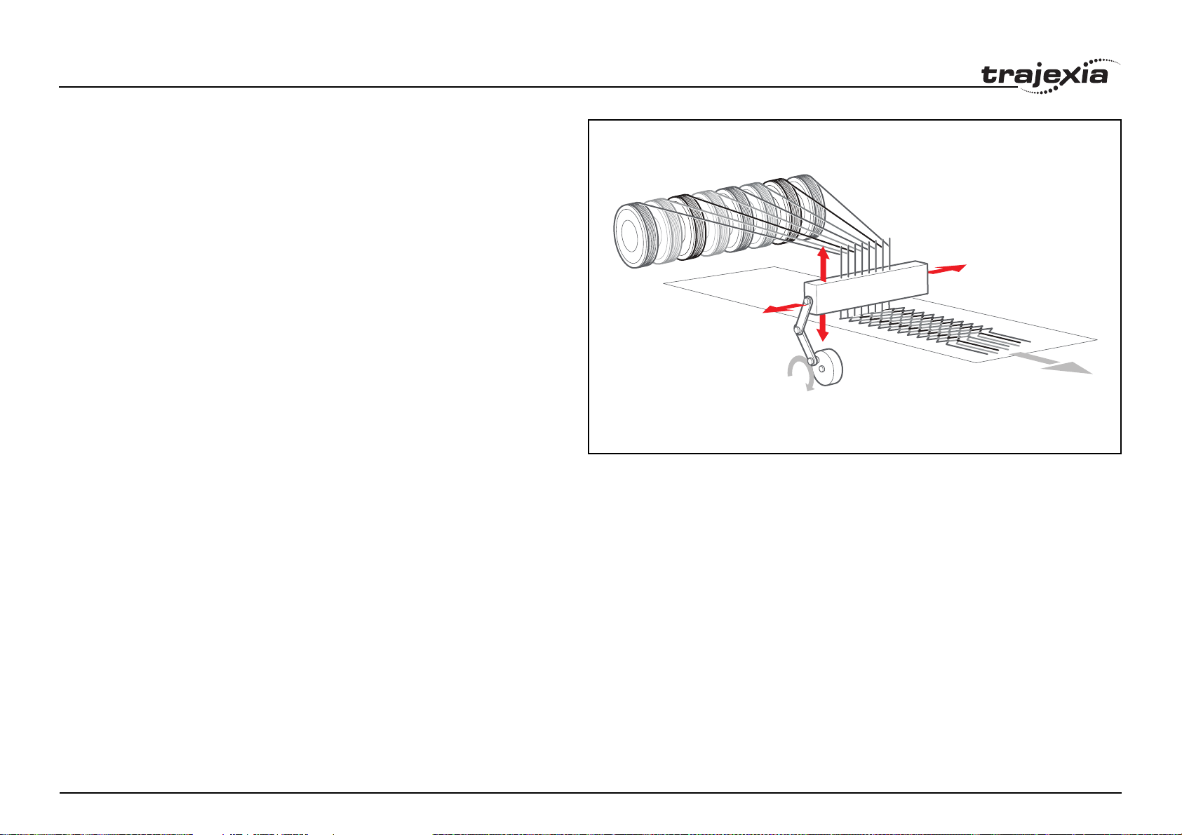
BASIC commands
Example A quilt stitching machine runs a feed cycle that stitches a plain pattern before
it starts a patterned stitch. The plain pattern must run for 1000 cycles. Then, it
must runs a pattern continuously, until requested to stop at the end of the pattern. The cam profile controls the motion of the needle bar between moves.
The pattern table controls the distance of the move to make the pattern.
The same shape is used for the initialisation cycles and the pattern. This
shape is held in TABLE values 100..150. The running pattern sequence is
held in TABLE values 1000..4999. The initialisation pattern is a single value
held in TABLE(160). The initialisation control block is held in
TABLE(200)..TABLE(206). The running control block is held in
TABLE(300)..TABLE(306).
' Set up Initialisation control block:
TABLE(200,160,-1,160,160,0,1000,300)
' Set up running control block:
TABLE(300,1000,-1,1000,4999,0,-1,-1)
' Run whole lot with single CAMBOX:
' Third parameter is pointer to first control block
CAMBOX(100,150,200,5000,1,20)
WAIT UNTIL IN(7)=OFF
TABLE(305,0) ' Set zero repeats: This will stop at end of pattern
Note: The axis to which the CAMBOX is linked can run in a positive or negative direction. In the case of a negative direction link, the pattern executes in
reverse. In the case where a certain number of pattern repeats is specified
with a negative direction link, the first control block produces one repeat less
than expected. This is because the CAMBOX loads a zero link position which
immediately goes negative on the next servo cycle triggering a REPEAT
COUNT. This effect only occurs when the CAMBOX is loaded, not on transitions from CONTROL BLOCK to CONTROL BLOCK. This effect can easily be
compensated for: either increase the required number of repeats, or set the
initial value of REPEAT POSITION to 1.
fig. 11/i
AXIS 0
AXIS 1
See also AXIS, CAM, REP_OPTION, TABLE
Revision 1.0
PROGRAMMING MANUAL 57
Page 64

BASIC commands
3.2.48 CAN_CORT
/i
Type System command
Syntax CAN_CORT(unit,4,0)
Retrieves the unit status. See the table in section 4.6.2.
CAN_CORT(unit,5,bit_rate)
Initialises the TJ1-CORT with the desired bit rate.
CAN_CORT(unit,6,node_ID,mandatory_flag)
Add a slave node to the TJ1-CORT and indicate whether it is permanently
available on the network.
CAN_CORT(unit,7,PDO_number,area_type,start_address,COB_ID,
obj_type, obj_type,…)
Configure an RPDO.
CAN_CORT(unit,8,PDO_number,area_type,start_address,COB_ID,
inhibit_time,event_timer,obj_type, obj_type,…)
Configure a TPDO.
CAN_CORT(unit,9,node_ID,index,subindex,byte1,byte2,…)
Make the TJ1-CORT configure an object in a slave during the CANopen network initialization.
CAN_CORT(unit,10)
Start the CANopen network and map the Trajexia memory to RPDOs and
TPDOs.
CAN_CORT(unit,11,mode)
Set the CANopen network to pre-operational or operational state.
CAN_CORT(unit,12,node_ID,index,subindex,VR_address)
Reads the value of a CANopen node object using an SDO (Service Data
Object) command into the VR array. Each byte of the returned value occupies
one VR address.
CAN_CORT(unit,13,node_ID,index,subindex,VR_address,data_len)
Write a value of a CANopen node object using an SDO command using the
VR array as source. Each VR address is interpreted as one byte of the value
that is written.
CAN_CORT(unit,14,node_ID,VR_address)
Reads the EMCY (emergency) message from a node into the VR array. Each
Revision 1.0
byte of the eight bytes occupies one VR address.
Description The CAN_CORT commands where the second argument is 4 through 10 are
normally used in a BASIC program that is run at startup. The sequence of the
CAN_CORT commands that configure a CANopen network is important.
Arguments • unit
The sequence number of the unit.
• bit_rate
The bit rate on the CAN bus. Valid values are 2 (500 Kbps), 3 (250
Kbps), 4 (125 Kbps), 5 (50 Kbps) and 6 (20 Kbps).
• node_ID
The CANopen node on the CAN bus.
• mandatory_flag
The mandatory flag of the node.
- 0 = optional, no error occurs when the node is not in the network.
- 1= mandatory, an error occurs when the node is not in the network.
• PDO_number
Identification of an individual PDO. PDO_number can range from 0 to 7.
• area_type
The memory area in Trajexia: 1 = VR, 2 = TABLE, 3 = Digital I/O, 4 =
Analog I/O.
• start_address
The array index in the VR, TABLE, IN, OP, AIN or AOUT array.
• COB_ID
The COB (Controller Object Identification) ID used to identify a PDO in a
CANopen network.
• obj_type
The CANopen object type. Valid values are: 2 = INT8, 3 = INT16, 4 =
INT32, 5 = UINT8, 6 = UINT16, 7 = UINT32.
• inhibit_time
The minimum time in 0.1 ms units between two consecutive transmissions of a TPDO.
• event_timer
The maximum time in ms units that is observed between two consecutive transmissions of a TPDO. If this value is 0, the time is unlimited. The
TPDO is sent only when the contents changes.
• index
The index of the addressed CANopen object.
• subindex
The subindex within the addressed CANopen object.
PROGRAMMING MANUAL 58
Page 65

BASIC commands
• mode
The CANopen network operation mode. 0 = pre-operational, 1 = operational.
• VR_address
The index in the VR array.
• data_len
The amount of bytes to transfer.
Example No example.
See also N/A
3.2.49 CANCEL
/i
Type Axis command
Syntax CANCEL[(1)]
CA[(1)]
Description The CANCEL command cancels the move on an axis or an interpolating axis
group. Speed-profiled moves (FORWARD, REVERSE, MOVE, MOVEABS,
MOVECIRC, MHELICAL and MOVEMODIFY) will be decelerated at the
deceleration rate as set by the DECEL parameter and then stopped. Other
moves will be immediately stopped.
The CANCEL command cancels the contents of the current move buffer
(MTYPE). The command CANCEL(1) cancels the contents of the next move
buffer (NTYPE) without affecting the current move in the MTYPE buffer.
CANCEL works on the default basis axis (set with BASE) unless AXIS is used
to specify a temporary base axis.
Note:
• CANCEL cancels only the presently executing move. If further moves are
buffered they will then be loaded.
• During the deceleration of the current move additional CANCELs will be
ignored.
• CANCEL(1) cancels only the presently buffered move. Any moves stored
in the task buffers indicated by the PMOVE variable can be loaded into
Revision 1.0
Arguments N/A
the buffer as soon as the buffered move is cancelled.
PROGRAMMING MANUAL 59
Page 66
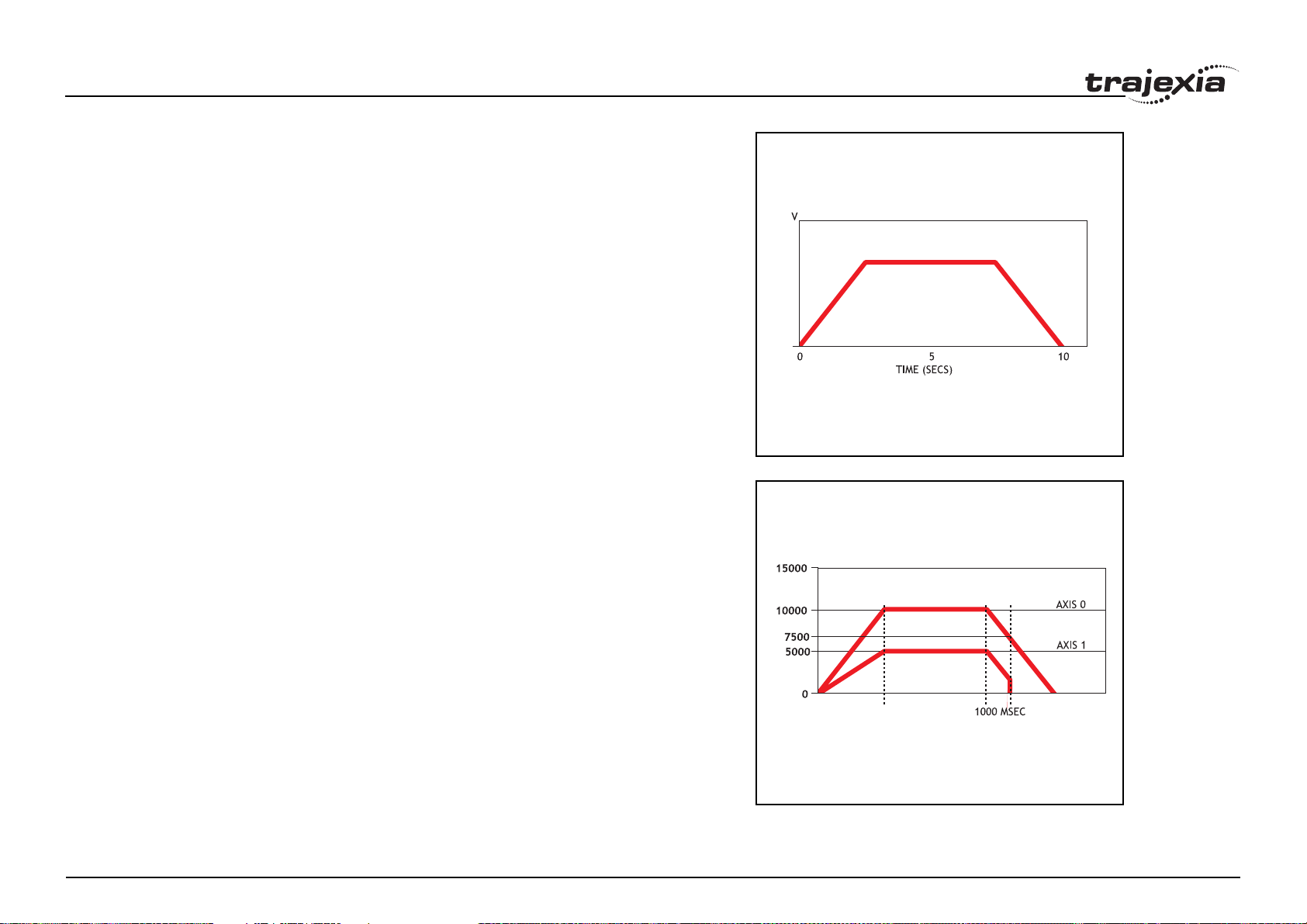
BASIC commands
Example FORWARD
WA(10000)
CANCEL ' Stop movement after 10 seconds
Example MOVE(1000)
MOVEABS(3000)
CANCEL ' Cancel the move to 3000 and move to 4000 instead.
MOVEABS(4000)
Note that the command MOVEMODIFY is a better solution for modifying end
points of moves in this case.
Example Two axes are connected with a ratio of 1:2. Axis 0 is cancelled after 1 second,
then axis 1 is cancelled when the speed drops to a specified level. After the
first cancel axis 1 decelerates at the DECEL rate. When the CONNECT of
axis 1 is cancelled, axis 1 stops instantly.
BASE(0)
SPEED=10000
FORWARD
CONNECT(0.5,0) AXIS(1)
WA(1000)
CANCEL
WAIT UNTIL VP_SPEED<=7500
CANCEL AXIS(1)
fig. 12/i
fig. 13/i
See also AXIS, MTYPE, NTYPE, PMOVE, RAPIDSTOP
Revision 1.0
PROGRAMMING MANUAL 60
Page 67
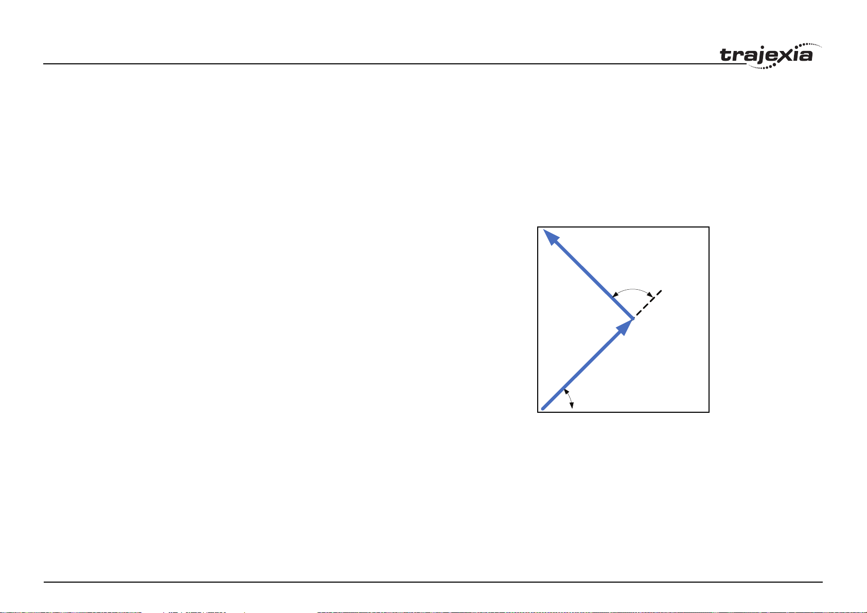
BASIC commands
3.2.50 CHANGE_DIR_LAST
/i
Type Axis parameter
Syntax CHANGE_DIR_LAST
Description Allows the program to examine the change in direction in radians of the last
programmed MOVESP/MOVEABSSP/MOVECIRCSP move of 2 or more
axes. CHANGE_DIR_LAST is always positive.
Arguments N/A
Example MOVESP(100,100)
PRINT "START_DIR_LAST: ";START_DIR_LAST/(2*PI)*360[0];" Deg"
PRINT "CHANGE_DIR_LAST: ";CHANGE_DIR_LAST/(2*PI)*360[0];" Deg"
PRINT "END_DIR_LAST: ";END_DIR_LAST/(2*PI)*360[0];" Deg"
PRINT
MOVESP(-100,100)
PRINT "START_DIR_LAST: ";START_DIR_LAST/(2*PI)*360[0];" Deg"
PRINT "CHANGE_DIR_LAST: ";CHANGE_DIR_LAST/(2*PI)*360[0];" Deg"
PRINT "END_DIR_LAST: ";END_DIR_LAST/(2*PI)*360[0];" Deg"
fig. 14/i
CHANGE_DIR_LAST=90°
Results in:
START_DIR_LAST: 45 Deg
CHANGE_DIR_LAST: 45 Deg
END_DIR_LAST: 45 Deg
START_DIR_LAST: -45 Deg
CHANGE_DIR_LAST: 90 Deg
END_DIR_LAST: -45 Deg
See also MOVESP, START_DIR_LAST, END_DIR_LAST
Revision 1.0
START_DIR_LAST=45°
PROGRAMMING MANUAL 61
Page 68

BASIC commands
3.2.51 CHECKSUM
/i
Type System parameter (read-only)
Syntax CHECKSUM
Description The CHECKSUM parameter contains the checksum for the programs in RAM.
At start-up, the checksum is recalculated and compared with the previously
held value. If the checksum is incorrect the program will not run.
Arguments N/A
Example No example.
See also N/A
3.2.52 CHR
/i
Type I/O command
Syntax CHR(x)
Description The CHR command is used to send individual ASCII characters which are
referred to by number. PRINT CHR(x); is equivalent to PUT(x) in some other
versions of BASIC.
Arguments • x
A BASIC expression.
Example >>PRINT CHR(65);
A
See also N/A
3.2.53 CLEAR
/i
Description The CLEAR command resets all global VR variables to 0 and sets local varia-
bles on the process on which the command is run to 0. When you use it in a
program it resets all local variables defined to 0.
Arguments N/A
Example >>VR(0)=22: VR(20)=44.3158: VR(300)=-12
>>PRINT VR(0), VR(20), VR(300)
22.0000 44.3158 -12.0000
>>CLEAR
>>PRINT VR(0), VR(20), VR(300)
0.0000 0.0000 0.0000
See also • RESET, VR
3.2.54 CLEAR_BIT
/i
Type System command
Syntax CLEAR_BIT(bit_number, vr_number)
Description The CLEAR_BIT command resets the specified bit in the specified VR varia-
ble. Other bits in the variable keep their values.
Arguments • bit_number
The number of the bit to be reset. Range: 0 - 52.
• vr_number
The number of the VR variable for which the bit will be reset. Range: 0 -
63999.
Example >>PRINT VR(17)
112.0000
>>CLEAR_BIT(5, 17)
>>PRINT VR(17)
80.0000
See also READ_BIT, SET_BIT, VR.
Type System command
Revision 1.0
Syntax CLEAR
PROGRAMMING MANUAL 62
Page 69
BASIC commands
3.2.55 CLEAR_PARAMS
/i
Type System command
Syntax CLEAR_PARAMS
Description Clears all variables and parameters stored in Flash-ROM to their default val-
ues. The CLEAR_PARAM will erase (set to 0) all the VR’s stored using
FLASHVR command. This command cannot be performed if the controller is
locked.
Arguments N/A
Example No example.
See also N/A
3.2.56 CLOSE_WIN
/i
Type Axis parameter
Syntax CLOSE_WIN
CW
Description The CLOSE_WIN axis parameter defines the end of the window inside or out-
side which a registration mark is expected. The value is in user units.
Description The CLUTCH_RATE axis parameter defines the change in connection ratio
when using the CONNECT command. The rate is defined as amount of ratio
per second.
The default value is set to a high value (1000000) in order to ensure compatibility with previous TJ2-MC64 units.
Note: The operation using CLUTCH_RATE is not deterministic in position. If
required, use the MOVELINK command instead to avoid unnecessary phase
difference between base axis and linked axis.
Arguments N/A
Example CLUTCH_RATE = 4
This setting will imply that when giving CONNECT(4,1), it will take one second to reach the full connection.
See also AXIS, CONNECT, MOVELINK.
3.2.58 COMMSERROR
/i
Type System parameter (read-only)
Syntax COMMSERROR
Description The COMMSERROR parameter contains the communication errors that
have occurred since the last time that it was initialized.
The bits in COMMSERROR are given in the table below.
Arguments N/A
Example CLOSE_WIN=10
See also AXIS, OPEN_WIN, REGIST, UNITS.
3.2.57 CLUTCH_RATE
/i
Type Axis parameter
Syntax CLUTCH_RATE
Revision 1.0
/i
Bit Description Error location
8 Port 1 Rx data ready Serial port 1
9 Port 1 Rx Overrun Serial port 1
10 Port 1 Parity Error Serial port 1
11 Port 1 Rx Frame Error Serial port 1
12 Port 2 Rx data ready Serial port 2
13 Port 2 Rx Overrun Serial port 2
14 Port 2 Parity Error Serial port 2
15 Port 2 Rx Frame Error Serial port 2
PROGRAMMING MANUAL 63
Page 70
BASIC commands
/i
Arguments N/A
Example No example.
See also N/A
3.2.59 COMMSTYPE
/i
Type Slot parameter
Syntax COMMSTYPE SLOT(unit_number)
Description This parameter returns the type of unit in a controller unit. The table below
lists the return values.
/i
Return value Description
0 Unused unit
31 TJ1-ML16
33 TJ1-FL02
34 TJ1-PRT
3.2.60 COMPILE
/i
Type Program command
Syntax COMPILE
Description The COMPILE command forces the compilation of the currently selected pro-
gram to intermediate code. Program are compiled automatically by the system software prior to program execution or when another program is selected.
This command is not therefore normally required.
Arguments N/A
Example No example.
See also N/A
35 TJ1-DRT
36 TJ1-ML04
38 TJ1-CORT
/i
Arguments • unit_number
Unit numbers are 0 to 6, with 0 being the unit immediately to the right of
the TJ2-MC64.
Example No example.
See also N/A
Revision 1.0
PROGRAMMING MANUAL 64
Page 71
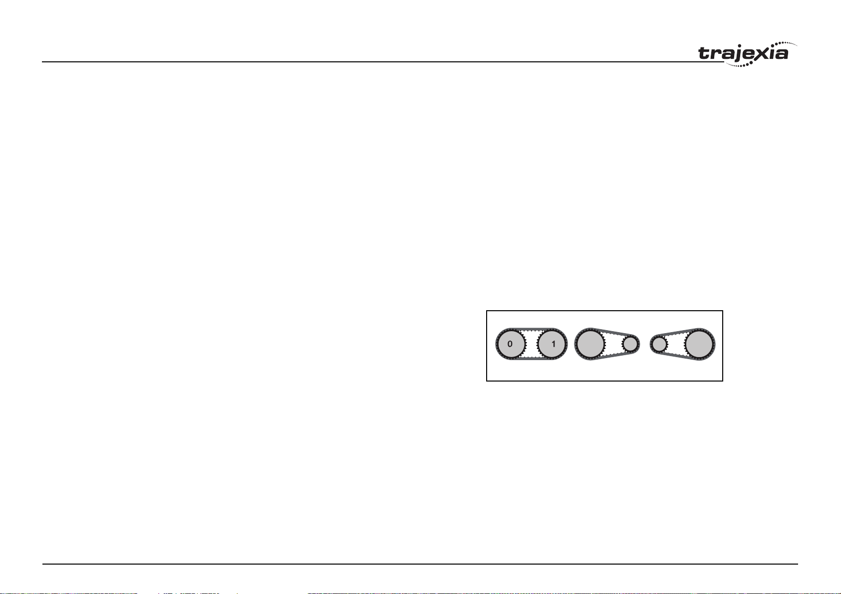
BASIC commands
3.2.61 CONNECT
/i
Type Axis command
Syntax CONNECT(ratio, driving_axis)
CO(ratio, driving_axis)
Description The CONNECT command connects the demand position of the base axis to
the measured movements of the axis specified by driving_axis to achieve an
electronic gearbox.
The ratio can be changed at any time by executing another CONNECT command on the same axis. To change the driving axis the CONNECT command
needs to be cancelled first. CONNECT with different driving axis will be
ignored. The CONNECT command can be cancelled with a CANCEL or
RAPIDSTOP command. The CLUTCH_RATE axis parameter can be used to
set a specified connection change rate.
CONNECT works on the default basis axis (set with BASE) unless AXIS is
used to specify a temporary base axis.
Arguments • ratio
The connection ratio of the gearbox. The ratio is specified as the encoder
edge ratio (not units). It holds the number of edges the base axis is
required to move per edge increment of the driving axis. The ratio value
can be either positive or negative and has sixteen bit fractional resolution.
• driving_axis
The Master axis which will drive the base axis.
Note: To achieve an exact connection of fractional ratio’s of values such
as 1024/3072 the MOVELINK command can be used with the continu-
ous repeat link option set to ON.
fig. 15/i
CONNECT (1,1) CONNECT (0.5,1) CONNECT (2,1)
Example In a press feed, a roller is required to rotate at a speed that is equal to one
quarter of the measured rate from an encoder installed on the incoming conveyor. The roller is wired to the master axis 0. The reference encoder is connected to axis 1.
Revision 1.0
BASE(0)
SERVO=ON
CONNECT(0.25,1)
PROGRAMMING MANUAL 65
Page 72
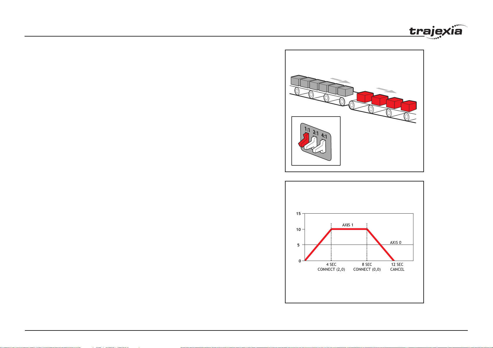
BASIC commands
Example A machine has an automatic feed on axis 1 that must move at a set ratio to
axis 0. This ratio is selected using inputs 0-2 to select a particular “gear”. This
ratio can be updated every 100 ms. Combinations of inputs select the intermediate gear ratios. For example, 1 ON and 2 ON gives a ratio of 6:1.
BASE(1)
FORWARD AXIS(0)
WHILE IN(3)=ON
WA(100)
gear = IN(0,2)
CONNECT(gear,0)
WEND
RAPIDSTOP cancel the FORWARD and the CONNECT
Example Axis 0 is required to run a continuous forward. Axis 1 must connect to axis 0.
If CONNECT is called, it results in a step change. Therefore, CLUTCH_RATE
is used, together with an initial and final connect ratio of zero, to get the
required motion.
FORWARD AXIS(0)
BASE(1)
CONNECT(0,0) 'set intitial ratio to zero
CLUTCH_RATE=0.5 'set clutch rate
CONNECT(2,0) 'apply the required connect ratio
WA(8000)
CONNECT(0,0) 'apply zero ratio to disconnect
WA(4000) 'wait for deceleration to complete
CANCEL 'cancel connect
fig. 16/i
fig. 17/i
See also AXIS, CANCEL, CLUTCH_RATE, CONNECT, RAPIDSTOP.
Revision 1.0
PROGRAMMING MANUAL 66
Page 73

BASIC commands
3.2.62 CONSTANT
/i
Type System command
Syntax CONSTANT ["name"[, value]]
Description Declares the name as a constant for use both within the program containing
the CONSTANT definition and all other programs in the Trajexia Studio
project.
Note: The program containing the CONSTANT definition must be run before
the name is used in other programs. In addition, only that program should be
running at the time the CONSTANT is executed, otherwise the program error
will appear and the program will stop when trying to execute this command.
For fast startup the program should also be the only process running at
power-up.
Using CONSTANT with only the name will erase the specified constant.
Using CONSTANT with no parameters will erase all CONSTANT declara-
tions. This also happens when the TJ2-MC64 is reset by switching the power
off and back on, or by executing the EX command.
A maximum of 256 CONSTANTs can be declared.
The maximum length of the name of the GLOBAL is 32 characters.
Arguments • name
Any user-defined name containing lower case alpha, numerical or underscore characters.
• value
The value assigned to name.
Example CONSTANT "nak", $15
CONSTANT "start_button", 5
IF IN(start_button)=ON THEN OP(led1, ON)
IF key_char=nak THEN GOSUB no_ack_received
See also LIST_GLOBAL
3.2.63 CONTROL
/i
Type System parameter (read-only)
Syntax CONTROL
Description The CONTROL parameter returns the type of TJ2-MC64 in the system. The
value of this system parameter for the TJ2-MC64 is 266..
Note: When the Machine Controller is locked, 1000 is added to above values,
so e.g. a locked TJ2-MC64 will return 1266.
Arguments N/A
Example No example.
See also N/A
3.2.64 COPY
/i
Type Program command
Syntax COPY program_name new_program_name
Description The COPY command copies an existing program in the controller to a new
program with the specified name. The program name can be specified without
quotes.
Note: This command is implemented for the Command Line Terminal. Within
Trajexia Studio users can select the command from the Program menu.
Arguments • program_name
Name of the program to be copied.
• new_program_name
Name to use for the new program.
Example >> COPY "prog" "newprog"
See also DEL, NEW, RENAME.
Revision 1.0
PROGRAMMING MANUAL 67
Page 74
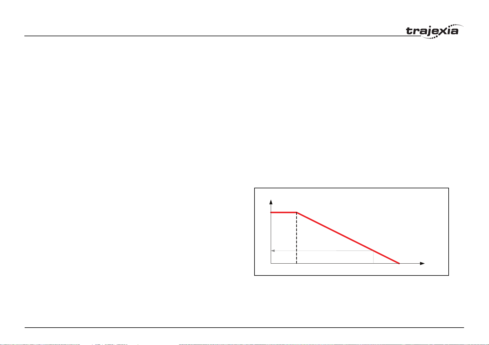
BASIC commands
3.2.65 CORNER_MODE
/i
Typ e Sys tem parameter
Syntax CORNER_MODE
Description Allows the program to control the cornering action:
Bit 0 - reserved for future use
Bit 1 - Enable use of DECEL_ANGLE and STOP_ANGLE
When enabling this function, the system will proportionaly reduce the speed
when a change in angle of two consecutive moves is between the angles
defined by DECEL_ANGLE and STOP_ANGLE.
Bit 2 - allows RAISE_ANGLE and CORNER_STATE interaction
Bit 3 - allows FULL_SP_RADIUS
It is possible to use combinations of these.
Arguments N/A
fig. 18/i
Example CORNER_MODE=2
In the following example the system will reduce the speed to 27.5% during an
change in angle of PI/4.
/i
Example Bit 2 - allows RAISE_ANGLE and CORNER_STATE interaction
See CORNER_STATE
Speed [%]
100
DECEL_ANGLE =0.2
STOP_ANGLE=1
27.5
Angle
1 rad0.2 rad 1/4PI=0.78 rad
Revision 1.0
PROGRAMMING MANUAL 68
Change
Page 75
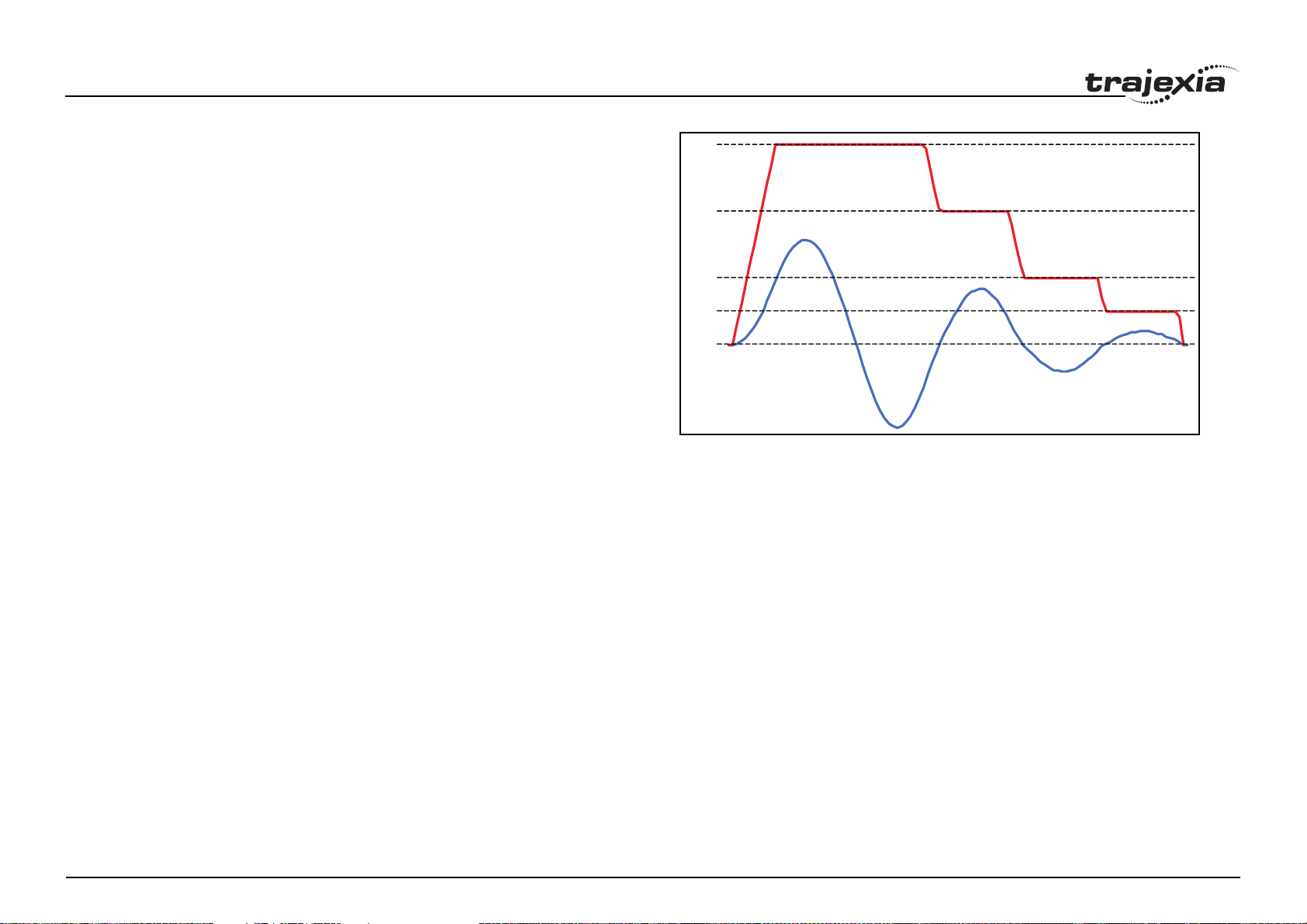
BASIC commands
Example Bit 3 - allows FULL_SP_RADIUS
In the following program, when the first two MOVECIRCSP is reached the
speed remains at 1000 because the radius (60) is greater than that set in
FULL_SP_RADIUS. The speeds of the following circular moves are reduced
to 60% (40/60), 30% (20/60) and 15% (20/60) because the radius is proportionally lower than that stored in FULL_SP_RADIUS.
BASE(0)
CORNER_MODE=8 'Enable use of FULL_SP_RADIUS (bit 3 ON)
FULL_SP_RADIUS=60
MERGE=ON
FORCE_SPEED=1000
ENDMOVE_SPEED=1000
MOVECIRCSP(150,0,75,0,1)
MOVECIRCSP(120,0,60,0,0)
MOVECIRCSP(80,0,40,0,1)
MOVECIRCSP(40,0,20,0,0)
MOVECIRCSP(20,0,10,0,1)
See also CORNER_STATE, DECEL_ANGLE, RAISE_ANGLE, STOP_ANGLE,
FULL_SP_RADIUS
fig. 19/i
1000
666
333
166
0
3.2.66 CORNER_STATE
/i
Type Axis parameter
Syntax CORNER_STATE
Description Allows a BASIC program to interact with the move loading process to facilitate
knife rotation at sharp corners. Bit 2 of CORNER_MODE must be set for this
functionality.
Description of the bits in CORNER_STATE:
Bit 1 - This bit is set when the change in direction is above RAISE_ANGLE
Bit 2 - Set this bit to continue at FHSPEED
Bit 3 - This bit is set when the axis is continuing at FHSPEED
Clear all bits to continue normal operation.
Revision 1.0
Arguments N/A
PROGRAMMING MANUAL 69
Page 76

BASIC commands
Example MOVEABSSP(x,y)
IF CHANGE_DIR_LAST>RAISE_ANGLE THEN
WAIT UNTIL CORNER_STATE>0
GOSUB raise
CORNER_STATE=3
WA(10)
WAIT UNTIL VP_SPEED AXIS(2)=0
GOSUB lower
CORNER_STATE=0
ENDIF
See also CORNER_MODE, RAISE_ANGLE, FHSPEED
3.2.67 COS
/i
Type Mathematical function
Syntax COS(expression)
Description The COS function returns the cosine of the expression. Input values are in
radians and may have any value. The result value will be in the range from -1
to 1.
Arguments • expression
Any valid BASIC expression.
Example >> PRINT COS(0)
1.0000
See also N/A
3.2.68 CRC16
/i
Type System command
Arguments • mode
Specifies the mode of the command.
0 = Initialises the command with the Polynomial
1 = Returns the CRC. Will return 0 if Initialise has not been run
• poly
Polynomial used as seed for CRC check range 0-65535 (or 0-$FFFF)
• data_source
Defines where the data is loaded
0 = TAB LE memory
1 = VR memory
• start
Start location of first byte
• end
End location of last byte
• reg
Initial CRC value. Normally $0 - $FFFF
Example Using TABLE memory:
poly = $90d9
reginit = $ffff
CRC16(0, poly) 'Initialise internal CRC table memory
TABLE(0,1,2,3,4,5,6,7,8) ‘Load data into table memory location 0-7
calc_crc = CRC16(1,0,0,7,reginit) 'Source Data=TABLE(0..7)
Example Using VR memory:
poly = $90d9
reginit = $ffff
CRC16(0, poly) 'Initialise internal CRC table memory
‘Load 6 bytes into VR memory location 0-5
FOR i=0 TO 5
VR(i)=i+1
NEXT i
calc_crc = CRC16(1,1,0,5,reginit) 'Source Data=VR(0)..VR(5)
See also N/A
Syntax mode=0: CRC16(mode, poly)
Revision 1.0
Description Calculates the 16 bit CRC of data stored in contiguous Table Memory or VR
mode=1: CRC16(mode, data_source, start, end, reg)
Memory locations.
PROGRAMMING MANUAL 70
Page 77

BASIC commands
3.2.69 CREEP
/i
Type Axis parameter
Syntax CREEP
Description The CREEP axis parameter contains the creep speed for the axis. The creep
speed is used for the slow part of an origin search sequence. CREEP can
have any positive value, including 0.
The creep speed is entered in units/sec with the unit conversion factor
UNITS. For example, if the unit conversion factor is set to the number of
encoder edges/inch, the speed is set in inches/sec.
Arguments N/A
Example BASE(2)
CREEP=10
SPEED=500
DATUM(4)
CREEP AXIS(1)=10
SPEED AXIS(1)=500
DATUM(4) AXIS(1)
See also AXIS, DATUM, UNITS.
3.2.70 D_GAIN
Example D_GAIN=0.25
See also • AXIS, I_GAIN, OV_GAIN, P_GAIN, VFF_GAIN.
3.2.71 D_ZONE_MAX
/i
Type System parameter
Syntax D_ZONE_MAX=value
Description This parameter works in conjunction with D_ZONE_MIN to clamp the DAC
output to zero when the demand movement is complete and the magnitude of
the Following Error is less than the D_ZONE_MIN value. The servo loop will
be reactivated when either the Following Error rises above the
D_ZONE_MAX value, or a fresh movement is started.
Arguments N/A
Example D_ZONE_MIN=3
D_ZONE_MAX=10
With these 2 parameters set as above, the DAC output will be clamped at
zero when the movement is complete and the Following Error falls below 3.
When a movement is restarted or if the Following Error rises above a value of
10, the servo loop will be reactivated.
See also D_ZONE_MIN.
/i
Type Axis parameter
Syntax D_GAIN
Description The D_GAIN axis parameter contains the derivative gain for the axis. The
derivative output contribution is calculated by multiplying the change in Following Error with D_GAIN. The default value is 0.
Add the derivative gain to a system to produce a smoother response and to
allow the use of a higher proportional gain that could not be used otherwise.
High values can cause oscillation.
Revision 1.0
Arguments N/A
Note: The servo gain must only be changed when the SERVO is off.
Note: Servo gains have no affect on stepper output axis, ATYPE=46.
3.2.72 D_ZONE_MIN
/i
Type System parameter
Syntax D_ZONE_MIN=value
Description This parameter works in conjunction with D_ZONE_MAX to clamp the DAC
output to zero when the demand movement is complete and the magnitude of
the Following Error is less than the D_ZONE_MIN value. The servo loop will
be reactivated when either the Following Error rises above the
D_ZONE_MAX value, or a fresh movement is started.
Arguments N/A
PROGRAMMING MANUAL 71
Page 78

BASIC commands
Example D_ZONE_MIN=3
D_ZONE_MAX=10
With these 2 parameters set as above, the DAC output will be clamped at
zero when the movement is complete and the Following Error falls below 3.
When a movement is restarted or if the Following Error rises above a value of
10, the servo loop will be reactivated.
See also D_ZONE_MAX.
3.2.73 DAC
See S_REF.
3.2.74 DAC_OUT
See S_REF_OUT.
3.2.75 DAC_SCALE
/i
Type Axis parameter
Syntax DAC_SCALE
Description The DAC_SCALE axis parameter is an integer multiplier which is applied
between the servo control loop output and the Digital to Analog Converter
which output is supplied to the Servo Drive. Its value is set to 16 on axes with
a 16 bit Digital to Analog Converter, which are Flex axis types. This scales
the values applied to the higher resolution DAC so that the gains required on
the axis are similar to those required on the other controllers.
DAC_SCALE may be set negative (-16) to reverse the polarity of the DAC
output signal. This is useful in case if e.g. absolute SSI encoder used has no
capability of changing default CW/CCW rotation direction and the default
direction is opposite to the one of the Servo Drive used.
Note: When the SERVO is OFF for a given axis, the magnitude of
DAC_SCALE is not important as the voltage applied is controlled by the DAC
Revision 1.0
parameter. The polarity is still reversed however by DAC_SCALE.
Note: The default DAC_SCALE value for MECHATROLINK-II axis types is 1.
Arguments N/A
Example DAC_SCALE AXIS(3)=-16
See also DAC, S_REF.
3.2.76 DATE
/i
Type System parameter
Syntax DATE
Description Returns or sets the current date held by the Trajexia' s real time clock. The
number may be entered in DD:MM:YY or DD:MM:YYYY format.
Arguments N/A
Example DATE=25:09:09
or
DATE=25:09:2009
Example >>PRINT DATE
3555
This prints the number representing the current day. This number is the
number of days since 1st January 2000, with 1 Jan. 1900 represented as 1.
See also N/A
3.2.77 DATE$
/i
Type System command
Syntax DATE$
Description Prints the current date DD/MMM/YYYY as a string to the communication port.
A 4-digit year description is given.
Arguments N/A
Example PRINT #1, DATE$
This will print the date in format for example: 20/Oct/2005
See also N/A
PROGRAMMING MANUAL 72
Page 79

BASIC commands
3.2.78 DATUM
/i
Type Axis command
Syntax DATUM(sequence)
Description The DATUM command performs one of 6 origin search sequences to position
an axis to an absolute position and also reset the error bits in AXISSTATUS
axis parameter.
DATUM uses both the creep and demand speed for the origin search. The
creep speed in the sequences is set with the CREEP axis parameter and the
demand speed is set with the SPEED axis parameter. The datum switch input
number, used for sequences 3 to 6, is set by the DATUM_IN parameter.
DATUM works on the default basis axis (set with BASE) unless AXIS is used
to specify a temporary base axis.
Note: The origin input set with the DATUM_IN parameter is active low, i.e., the
origin switch is set when the input is OFF. The feedhold, reverse jog, forward
jog, forward and reverse limit inputs are also active low. Active low inputs are
used to enable fail-safe wiring.
Arguments • sequence
See the table below.
/i
sequence
value
0The DATUM(0) command will clear the motion error. The currently measured
Revision 1.0
Description
position is set as the demand position (this is especially useful on stepper
axes with position verification). DATUM(0) also clears the Following Error that
exceeded the FE_LIMIT condition in the AXISSTATUS register for ALL axes.
It sets these bits in AXISSTATUS to zero:
Bit 1 : Following Error Warning.
Bit 2 : Remote Drive Comms Error.
Bit 3 : Remote Drive Error.
Bit 8 : Following Error Limit Exceeded.
Bit 11 : Cancelling Move.
Note that the status can not be cleared if the cause of the problem is still
present. DATUM(0) must only be used after the WDOG is set to OFF, other-
wise there will be unpredictable errors on the motion.
sequence
value
1 The axis moves at creep speed forward until the Z marker is encountered.
2 The axis moves at creep speed in reverse until the Z marker is encountered.
3 The axis moves at the demand speed forward until the datum switch is
4 The axis moves at the demand speed in reverse until the datum switch is
5 The axis moves at demand speed forward until the datum switch is reached.
6 The axis moves at demand speed reverse until the datum switch is reached.
Description
The demand position is then reset to 0 and the measured position corrected
so as to maintain the Following Error.
The demand position is then reset to 0 and the measured position corrected
so as to maintain the Following Error.
reached. The axis then moves reverse at creep speed until the datum switch
is reset. The demand position is then reset to 0 and the measured position
corrected so as to maintain the Following Error.
reached. The axis then moves forward at creep speed until the datum switch
is reset. The demand position is then reset to 0 and the measured position
corrected so as to maintain the Following Error.
The axis then reverses at creep speed until the datum switch is reset. The
axis continues in reverse at creep speed until the Z marker of the encoder is
encountered. The demand position is then reset to 0 and the measured position corrected so as to maintain the Following Error.
The axis then moves forward at creep speed until the datum switch is reset.
The axis continues forward at creep speed until the Z marker of the encoder is
encountered. The demand position is then reset to 0 and the measured position corrected so as to maintain the Following Error.
PROGRAMMING MANUAL 73
Page 80
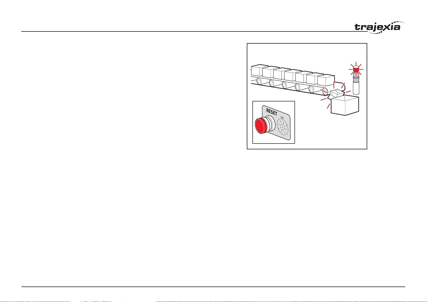
BASIC commands
Example A production line must stop if something blocks the product belt, which
causes a motion error. The obstacle must be removed, and a reset button
must be pressed to restart the line.
FORWARD 'start production line
WHILE IN(2)=ON
IF MOTION_ERROR=0 THEN
OP(8,ON) 'green light on; line is in motion
ELSE
OP(8, OFF)
GOSUB error_correct
ENDIF
WEND
CANCEL
STOP
error_correct:
REPEAT
OP(10,ON)
WA(250)
OP(10,OFF) 'flash red light to show crash
WA(250)
UNTIL IN(1)=OFF
DATUM(0) 'reset axis status errors
SERVO=ON 'turn the servo back on
WDOG=ON 'turn on the watchdog
OP(9,ON) 'sound siren that line will restart
WA(1000)
OP(9,OFF)
FORWARD 'restart motion
RETURN
fig. 20/i
Revision 1.0
PROGRAMMING MANUAL 74
Page 81
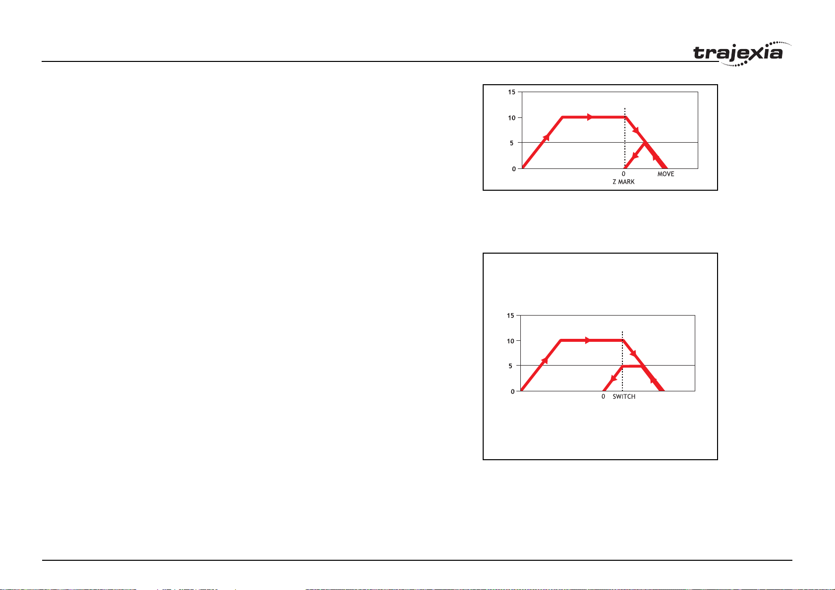
BASIC commands
Example The position of an axis must be defined by the Z marker. This position must
be set to zero. Then the axis must move to this position. Using the datum 1
the zero point is set on the Z mark. But the axis starts to decelerate at this
point, and therefore it stops after the mark. A move is used to bring it back to
the Z position.
SERVO=ON
WDOG=ON
CREEP=1000 'set the search speed
SPEED=5000 'set the return speed
DATUM(1) 'register on Z mark and sets this to datum
WAIT IDLE
MOVEABS (0) 'moves to datum position
Example A machine must return to its home position defined by the limit switch which is
found at the rear of the move before operation. This can be achieved through
using DATUM(4) which moves in reverse to find the switch.
SERVO=ON
WDOG=ON
REV_IN=-1 'temporarily turn off the limit switch function
DATUM_IN=5 'sets input 5 for registration
SPEED=5000 'set speed, for quick location of limit switch
CREEP=500 'set creep speed for slow move to find edge of switch
DATUM(4) 'find edge at creep speed and stop
WAIT IDLE
DATUM_IN=-1
REV_IN=5 'restore input 5 as a limit switch again
fig. 21/i
fig. 22/i
Revision 1.0
PROGRAMMING MANUAL 75
Page 82
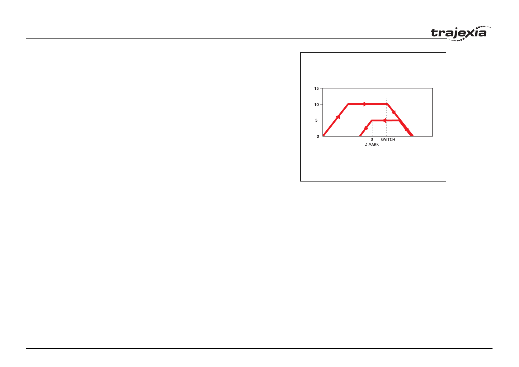
BASIC commands
Example A machine similar to the machine in the example above must locate a home
switch, which is at the forward end of the move. The machine then moves
backwards to the next Z marker, and set this Z marker as the
datum. This is done with DATUM(5), which moves forward at SPEED to
locate the switch, then reverses at CREEP to the Z marker. If required, a
move is made to the datum Z marker.
SERVO=ON
WDOG=ON
DATUM_IN=7 'sets input 7 as home switch
SPEED=5000 'set speed, for quick location of switch
CREEP=500 'set creep speed for slow move to find edge of switch
DATUM(5) 'start the homing sequence
WAIT IDLE
See also ACCEL, AXIS, AXISSTATUS, CREEP, DATUM_IN, DECEL,
MOTION_ERROR, SPEED.
fig. 23/i
Revision 1.0
PROGRAMMING MANUAL 76
Page 83

BASIC commands
3.2.79 DATUM_IN
/i
Type Axis parameter
Syntax DATUM_IN
DAT_IN
Description The DATUM_IN axis parameter contains the input number to be used as the
datum switch input for the DATUM command. The valid input range is given
by 0 to 31. Values 0 to 15 represent physically present inputs of TJ2-MC64 I/
O connector and are common for all axes.
Values 16 to 31 are mapped directly to Drive inputs that are present on the
CN1 connector. They are unique for each axis. It depends on the type of
Servo Drive which Servo Drive inputs are mapped into inputs 16 to 31.
Note: The origin input is active low, i.e., the origin switch is set when the input
is OFF. The feedhold, reverse jog, forward jog, forward and reverse limit
inputs are also active low. Active low inputs are used to enable fail-safe wiring.
Arguments N/A
Example DATUM_IN AXIS(0)=5
See also AXIS, DATUM.
3.2.80 DAY
/i
Type System parameter (read only)
3.2.81 DAY$
/i
Type System command
Syntax DAY$
Description Prints the current day as a string.
Arguments N/A
Example >>? DAY$
Wednesday
See also N/A
3.2.82 DECEL
/i
Type Axis parameter
Syntax DECEL
Description The DECEL axis parameter contains the axis deceleration rate. The rate is
set in units/s
Arguments N/A
Example DECEL = 100 ' Set deceleration rate
PRINT " Deceleration rate is ";DECEL;" mm/s/s"
See also ACCEL, AXIS, UNITS.
2
. The parameter can have any positive value including 0.
Syntax DAY
Description Returns the current day as a number 0..6, Sunday is 0.
Arguments N/A
Example >>? DAY
3.0000
See also N/A
Revision 1.0
3.2.83 DECEL_ANGLE
/i
Type Axis parameter
Syntax DECEL_ANGLE
Description Used to define the angle change in radians above which an X-Y system
should start to decelerate. Operation of DECEL_ANGLE applies to forced
speed moves and depends on setting of STOP_ANGLE and
CORNER_MODE.
PROGRAMMING MANUAL 77
Page 84

BASIC commands
Arguments N/A
Example ' Decelerate above 15 deg (0.2618 rad)
DECEL_ANGLE = 0.2618
See also ACCEL, AXIS, UNITS.
3.2.84 DEFPOS
/i
Type Axis command
Syntax DEFPOS(pos_1 [ , pos_2 [ , pos_3 [ , pos_4 [, ...]]]])
DP(pos_1 [ , pos_2 [ , pos_3 [ , pos_4 [, ...]]]])
Description The DEFPOS command defines the current demand position (DPOS) as a
new absolute position. The measured position (MPOS) will be changed
accordingly in order to keep the Following Error. DEFPOS is typically used
after an origin search sequence (see DATUM command), as this sets the current position to 0. DEFPOS can be used at any time.
As an alternative also the OFFPOS axis parameter can be used. This parameter can be used to perform a relative adjustment of the current position.
DEFPOS works on the default basis axis or axis sequence group (set with
BASE) unless AXIS is used to specify a temporary base axis.
Note: The changes to the axis position made using DEFPOS or OFFPOS are
made on the next servo update. This can potentially cause problems when a
move is initiated in the same servo period as the DEFPOS or OFFPOS.
The following example shows how the OFFPOS parameter can be used to
avoid this problem. DEFPOS commands are internally converted into
OFFPOS position offsets, which provides an easy way to avoid the problem
by programming as follows:
DEFPOS(100): WAIT UNTIL OFFPOS = 0: MOVEABS(0)
Arguments The command can take up to 64 arguments.
• pos_i
The absolute position for (base+i) axis in user units. Refer to the BASE
command for the grouping of the axes.
Revision 1.0
PROGRAMMING MANUAL 78
Page 85
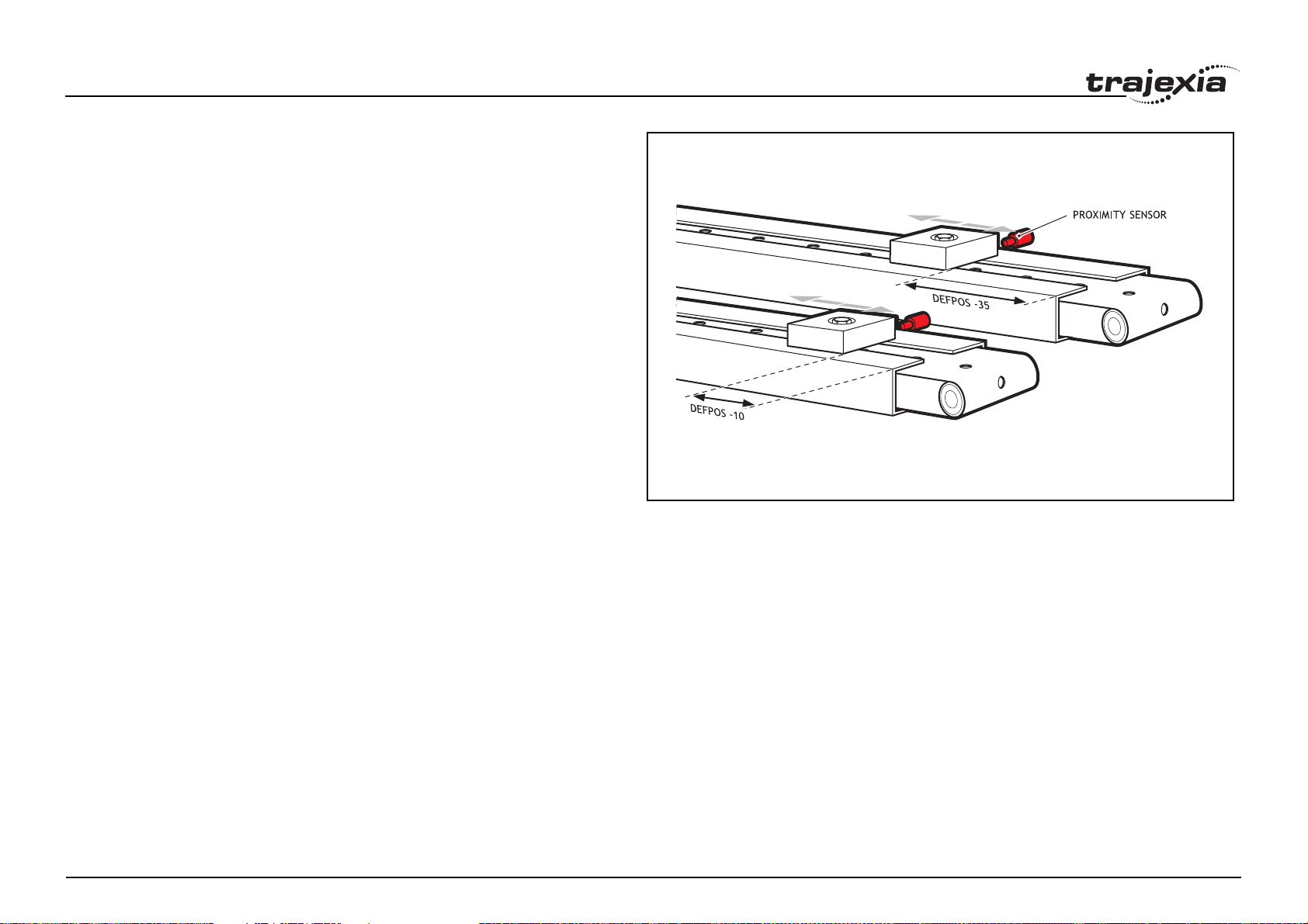
BASIC commands
Example After 2 axes returned to their homing positions, it is required to change the
DPOS values so that the home positions are not zero, but some defined positions instead.
DATUM(5) AXIS(1) ' home both axes. At the end of the DATUM
DATUM(4) AXIS(3) ' procedure, the positions are 0,0.
WAIT IDLE AXIS(1)
WAIT IDLE AXIS(3)
BASE(1,3) ' set up the BASE array
DEFPOS(-10,-35) ' define positions of the axes to be -10 and -35
fig. 24/i
Revision 1.0
PROGRAMMING MANUAL 79
Page 86
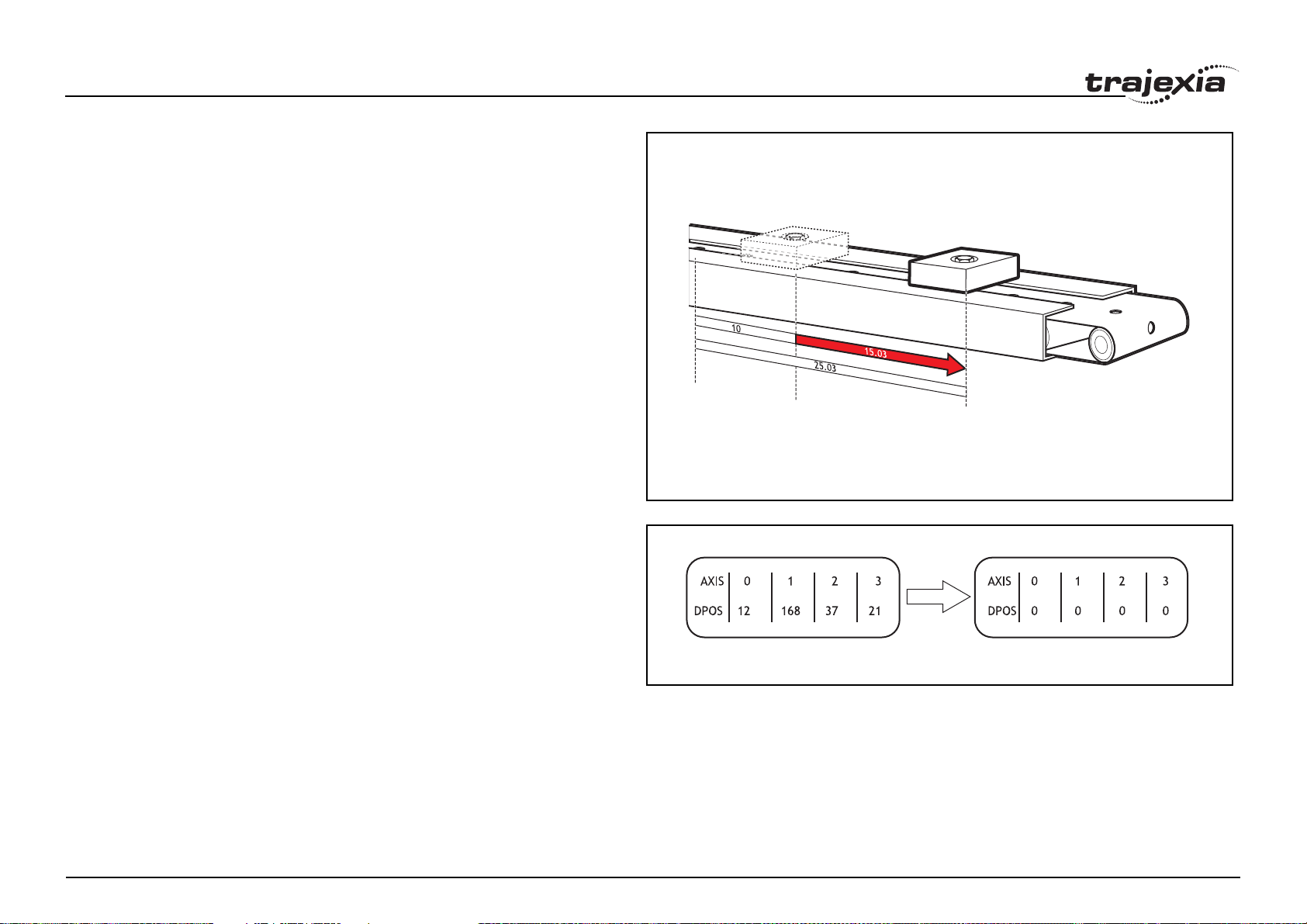
BASIC commands
Example Set the axis position to 10, then start an absolute move, but make sure the
axis has updated the position before loading the MOVEABS.
DEFPOS(10.0)
WAIT UNTIL OFFPOS=0
' Makes sure that DEFPOS is complete before next line
MOVEABS(25.03)
fig. 25/i
fig. 26/i
Example From the Command Line of the Terminal window, quickly set the DPOS val-
ues of the first four axes to 0.
>>BASE(0)
>>DP(0,0,0,0)
See also AXIS, DATUM, DPOS, OFFPOS, MPOS, UNITS.
BEFORE AFTER
Revision 1.0
PROGRAMMING MANUAL 80
Page 87
BASIC commands
3.2.85 DEL
/i
Type Program command
Syntax DEL [program_name]
RM [program_name]
Description The DEL command deletes a program from the controller. DEL without a pro-
gram name can be used to delete the currently selected program (using
SELECT). The program name can also be specified without quotes. DEL ALL
will delete all programs.
DEL can also be used to delete the Table: DEL "TABLE". The name
"TABLE" must be in quotes.
Note: This command is implemented for the Command Line Terminal. Within
Trajexia Studio users can select the command from the Program menu.
Arguments • program_name
Name of the program to be deleted.
Example >> DEL oldprog
See also COPY, NEW, RENAME, SELECT, TABLE.
3.2.86 DEMAND_EDGES
/i
Type Axis parameter (read-only)
Syntax DEMAND_EDGES
Description The DEMAND_EDGES axis parameter contains the current value of the
DPOS axis parameter in encoder edge units.
Arguments N/A
Example No example.
See also AXIS, DPOS.
Revision 1.0
3.2.87 DEVICENET
/i
Type System command
Syntax DEVICENET(unit_number, 2, 1, VR_start_outputs, no_outputs,
VR_start_inputs, no_inputs)
DEVICENET(unit_number, 4, 0)
Description DEVICENET function 2 configures the TJ1-DRT for data exchange with the
DeviceNet master unit and defines areas in the VR memory where I/O
exchange takes place. DEVICENET function 4 returns the data exchange status of the TJ1-DRT. Refer to the table below for the description of the bits in
the data exchange status word.
/i
Bit Value Description
0 0 Command DEVICENET (unit_number, 2, ...) not executed yet
1 Command DEVICENET (unit_number, 2, ...) executed without error
1 0 No DeviceNet I/O connection
1 DeviceNet I/O connection running
2 0 VR variables in the output data range have been updated
1 VR variables in the output data range have not been updated yet
3 0 DeviceNet I/O connection size matches the DEVICENET
(unit_number, 2,…) command
1 DeviceNet I/O connection size does not match the
DEVICENET(unit_number, 2,…) command
4-7 0 Always zero
8 0 Network power OK
1 Network power failure
9 0 No BUSOFF occurred
1 BUSOFF occurred
PROGRAMMING MANUAL 81
Page 88
BASIC commands
Bit Value Description
10 0 No node address duplication error
1 Node address duplication error
/i
Arguments • unit_number
Specifies the unit number of the TJ1-DRT in the Trajexia system.
• VR_start_outputs
The starting address in VR memory of the controller where the output
data from the DeviceNet master is located.
• no_outputs
The number of output words from the DeviceNet master in VR memory.
• VR_start_inputs
The starting address in VR memory of the controller where the input data
for the DeviceNet master is located.
• no_inputs
The number of input words to the DeviceNet master in VR memory.
Example DEVICENET (0,2,1,10,16,150,31)
In this example, the TJ1-DRT is configured to exchange data with DeviceNet
master with 16 output words (received from the master) located at VR(10) to
VR(25), and 31 input words (sent to the master) located at VR(150) to
VR(180).
See also N/A
3.2.88 DIR
/i
Type Program command
Syntax DIR
LS
Description The DIR command shows a list of the programs held in the controller, the
memory size and the RUNTYPE. DIR also shows the available memory size,
Revision 1.0
power up mode and current selected program of the controller.
Note: This command is implemented for the Command Line Terminal only.
Example No example.
See also FREE, PROCESS, RUNTYPE, SELECT.
3.2.89 DISABLE_GROUP
/i
Type Axis command
Syntax DISABLE_GROUP(-1)
DISABLE_GROUP(axis_1 [, axis_2 [, ...]] )
Description The DISABLE_GROUP is used to create a group of axes which will be disa-
bled if there is a motion error in any or more axes in the group. After the group
is made, when an error occurs on one they will all have their AXIS_ENABLE
set OFF and SERVO set OFF. Multiple groups can be made, although an axis
cannot belong to more than one group. All groupings can be cleared using
DISABLE_GROUP(-1).
Note: For use with MECHATROLINK-II only..
Arguments • axis_i
A BASIC expression that evaluates to an axis number.
Example A machine has 2 functionally separate parts, which have their own emergency
stop and operator protection guarding. If there is an error on one part of the
machine, the other part can continue to run while the cause of the error is
removed and the axis group restarted. For this, 2 separate axis groupings
must be set up.
DISABLE_GROUP(-1) ' remove any previous axis groupings
DISABLE_GROUP(0,1,2,6) ' group axes 0 to 2 and 6
DISABLE_GROUP(3,4,5,7) ' group axes 3 to 5 and 7
WDOG=ON ' turn on the enable relay and the remote drive enable
FOR ax=0 TO 7
AXIS_ENABLE AXIS(ax)=ON ' enable the 8 axes
SERVO AXIS(ax)=ON ' start position loop servo for each axis
NEXT ax
Arguments N/A
PROGRAMMING MANUAL 82
Page 89
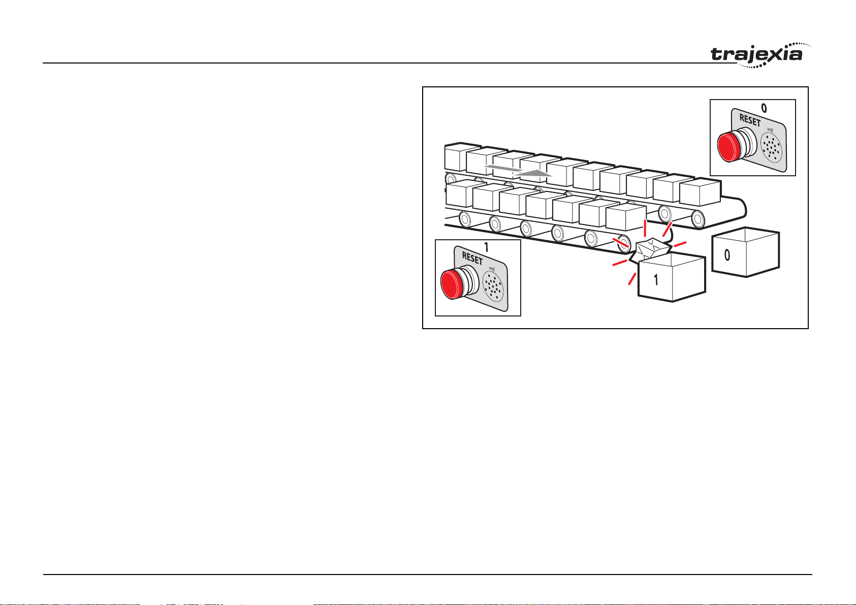
BASIC commands
Example Two conveyors operated by the same Motion Coordinator are required to run
independently, to make sure that the second conveyor does not stop if the
first conveyor is blocked.
DISABLE_GROUP(0) 'put axis 0 in its own group
DISABLE_GROUP(1) 'put axis 1 in another group
GOSUB group_enable0
GOSUB group_enable1
WDOG=ON
FORWARD AXIS(0)
FORWARD AXIS(1)
WHILE TRUE
IF AXIS_ENABLE AXIS(0)=0 THEN
PRINT "motion error axis 0"
reset_0_flag=1
ENDIF
IF AXIS_ENABLE AXIS(1)=0 THEN
PRINT "motion error axis 1"
reset_1_flag=1
ENDIF
IF reset_0_flag=1 AND IN(0)=ON THEN
GOSUB group_enable0
FORWARD AXIS(0)
reset_0_flag=0
ENDIF
IF reset_1_flag=1 AND IN(1)=ON THEN
GOSUB group_enable1
FORWARD AXIS(1)
reset_1_flag=0
ENDIF
WEND
group_enable0:
BASE(0)
DATUM(0) ' clear motion error on axis 0
WA(10)
Revision 1.0
AXIS_ENABLE=ON
RETURN
group_enable1:
BASE(1)
fig. 27/i
AXIS 0
AXIS 1
PROGRAMMING MANUAL 83
Page 90
BASIC commands
DATUM(0) ' clear motion error on axis 0
WA(10)
AXIS_ENABLE=ON
SERVO=ON
RETURN
Example One group of axes in a machine must be reset if a motion error occurs, with-
out affecting the remaining axes. This must be done manually by clearing the
cause of the error, pressing a button to clear the error flags of the controllers
and re-enabling the motion.
DISABLE_GROUP(-1) 'remove any previous axis groupings
DISABLE_GROUP(0,1,2) 'group axes 0 to 2
GOSUB group_enable 'enable the axes and clear errors
WDOG=ON
SPEED=1000
FORWARD
WHILE IN(2)=ON
check axis 0, but all axes in the group will disable together
IF AXIS_ENABLE =0 THEN
PRINT "Motion error in group 0"
PRINT "Press input 0 to reset"
IF IN(0)=0 THEN 'checks if reset button is pressed
GOSUB group_enable 'clear errors and enable axis
FORWARD 'restarts the motion
ENDIF
ENDIF
WEND
STOP 'stop program running into sub routine
group_enable: 'Clear group errors and enable axes
DATUM(0) 'clear any motion errors
WA(10)
FOR axis_no=0 TO 2
AXIS_ENABLE AXIS(axis_no)=ON 'enable axes
SERVO AXIS(axis_no)=ON 'start position loop servo
NEXT axis_no
RETURN
See also N/A
Revision 1.0
3.2.90 DISPLAY
/i
Type System parameter
Syntax DISPLAY=value
Description Determines the I/O channels to be displayed on the front panel LEDs. The
DISPLAY parameter may be used to select which bank of I/O should be displayed. The parameter default value is 0.
The values are in the table below.
/i
value Description
0 Inputs 0 to 7 (default)
1 Inputs 8 to 15
2 Inputs 16 to 23
3 Inputs 24 to 31
4 Outputs 0 to 7 (not used on Trajexia)
5 Outputs 8 to 15
6 Outputs 16 to 23
7 Outputs 24 to 31
/i
Arguments N/A
Example DISPLAY=5
Shows outputs 8-15.
See also N/A
3.2.91 DPOS
/i
Type Axis parameter (read-only)
Syntax DPOS
PROGRAMMING MANUAL 84
Page 91
BASIC commands
Description The DPOS axis parameter contains the demand position in user units, which
is generated by the move commands in servo control. When the controller is
in open loop (SERVO=OFF), the measured position (MPOS) will be copied to
the DPOS in order to maintain a 0 Following Error.
The range of the demand position is controlled with the REP_DIST and
REP_OPTION axis parameters. The value can be adjusted without doing a
move by using the DEFPOS command or OFFPOS axis parameter. DPOS is
reset to 0 at start-up or controller reset.
Arguments N/A
Example >> PRINT DPOS AXIS(0)
34.0000
The above line will return the demand position in user units.
See also AXIS, DPOS, DEFPOS, DEMAND_EDGES, FE, MPOS, REP_DIST,
REP_OPTION, OFFPOS, UNITS.
3.2.92 DRIVE_ALARM
/i
Type Axis command
Syntax DRIVE_ALARM(VR)
Description The DRIVE_ALARM function reads the current alarm of the Servo Drive that
is connected to the Trajexia system via MECHATROLINK-II. Upon successful
execution, the command returns -1 and stores the value in the VR memory
location specified by the VR parameter. If the command cannot be executed,
the value 0 is returned. The command is executed on the Drive for the base
axis set by BASE. The base axis can be changed with the AXIS modifier, as
with all the other axis commands and parameters.
This command waits for the response from the axis, The execution of the
command can be slow and variable in time. If you require a quick response
do not use this command.
Arguments • VR
The alarm value is stored on the VR address on successful execution.
Revision 1.0
Example IF NOT DRIVE_ALARM(10) AXIS(2)THEN
PRINT "Failed to readalarm for Servo Drive"
ELSE
IF VR(10) = 0THEN
PRINT "ServoDrive healthy"
ELSE
PRINT "Servoalarm code: "; VR(10)
ENDIF
ENDIF
This example reads an alarm of the Servo Drive driving axis 2 and present
that information to the user.
See also N/A
3.2.93 DRIVE_CLEAR
/i
Type Axis command
Syntax DRIVE_CLEAR
Description The DRIVE_CLEAR command clears the alarm status of the Servo Drive
connected via the MECHATROLINK-II bus. This command is not capable of
clearing all the possible alarm states. Some alarms can only be cancelled by
turning off the power supply (both the TJ2-MC64 and the Servo Drive), and
then turning it on again. Also, an alarm will not be cleared if the cause of the
alarm is still present. The command is executed on the Drive for the base axis
set by BASE. The base axis can be changed with the AXIS modifier, as with
all the other axis commands and parameters.
Arguments N/A
Example No example.
See also DRIVE_STATUS.
Caution
Be sure that no Parameter Unit or Personal Computer Software is
connected to the Servo Drive when executing this command. Otherwise the program task will be paused until the connection of the
other device to the Servo Drive is removed.
PROGRAMMING MANUAL 85
Page 92
BASIC commands
3.2.94 DRIVE_CONTROL
/i
Type Axis parameter
Syntax DRIVE_CONTROL
Description When applied to an axis driven by the Servo Drive connected to the system
via the MECHATROLINK-II bus, this parameter selects the data to be monitored by DRIVE_MONITOR according to the table below.
/i
Code Description
2 Following error (this is the real FE when ATYPE=40 is used)
8 Feedback speed (With ATYPE=41 Units=Max Speed/40000000H, with other
ATYPE Units= reference units/s)
9 Command speed (units same as in Feedback Speed)
10 Target speed (units same as in Feedback Speed)
11 Torque (Force) reference (With ATYPE=42 Units=Max Torque/40000000H, with
other ATYPE Units= % over nominal Torque
14 Monitor selected with Pn813.0 Useful to monitor servo monitors (Unxxx)
15 Monitor selected with Pn813.1 Useful to monitor servo monitors (Unxxx)
/i
When applied to an axis driven by the Servo Drive connected to the system
via the TJ1-FL02, this parameter sets outputs of the TJ1-FL02. Set bit 8 of
this parameter to switch on OUT 0 for an axis. Set bit 9 of this parameter to
switch on OUT 1 for an axis. Keep in mind that the same outputs are used by
the HW_PSWITCH command.
The command is executed on the Drive for the base axis set by BASE. The
base axis can be changed with the AXIS modifier, as with all the other axis
commands and parameters.
Arguments N/A
Revision 1.0
Example DRIVE_CONTROL AXIS(2) = 256
In this example, OUT 0 is switched on for axis 2, connected using the TJ1FL02.
See also N/A
3.2.95 DRIVE_INPUTS
/i
Type Axis parameter
Syntax DRIVE_INPUTS
Description This parameter monitors the status of the inputs of the Servo Drive connected
via the MECHATROLINK-II bus. The parameter value is updated each
SERVO_PERIOD cycle. It is a bit-wise word with the bits as listed in the table
below.
/i
Bit no. Servo Drive input signal Description
Sigma-II Sigma-V Junma G/G5-
series
0 P_OTP_OTP_OTP_OTForward limit switch
1 N_OTN_OTN_OTN_OTReverse limit switch
2 DEC DEC /DEC DEC Zero point return deceleration
3 PA PA Not used Not used Encoder A phase signal
4 PB PB Not used Not used Encoder B phase signal
5 PC PC Not used PC Encoder C phase signal
6 EXT1 EXT1 /EXT1 EXT1 First external latch signal
7 EXT2 EXT2 Not used EXT2 Second external latch signal
8 EXT3 EXT3 Not used EXT3 Third external latch signal
9 BRK BRK /BRK BRK Brake output
10 Reserved HBB E-STP E-STP Emergency stop switch
11 Reserved Reserved Not used SI2 General input 2
12 IO12 IO12 Not used PCL General input 12 (Sigma-II
and Sigma-V), Torque limit
input in positive direction (G/
G5)
PROGRAMMING MANUAL 86
Page 93
BASIC commands
Bit no. Servo Drive input signal Description
Sigma-II Sigma-V Junma G/G5-
series
13 IO13 IO13 Not used NCL General input 13 (Sigma-II
and Sigma-V), Torque limit
input in negative direction (G/
G5)
14 IO14 IO14 Not used SI0 General input 14 (Sigma-II
and Sigma-V), General input
0 (G/G5)
15 IO15 IO15 Not used SI1 General input 15 (Sigma-II
and Sigma-V), General input
1 (G/G5)
/i
Refer to section 5.1.4 for more information about mapping Servo Drive inputs
and outputs.
The command is executed on the Drive for the base axis set by BASE. The
base axis can be changed with the AXIS modifier, as with all the other axis
commands and parameters.
Arguments N/A
Example No example.
See also N/A
3.2.96 DRIVE_MONITOR
/i
Type Axis parameter
Syntax DRIVE_MONITOR
Revision 1.0
Description This parameter contains the monitored data of the Servo Drive connected to
the system via the MECHATROLINK-II bus. The data to be monitored is
selected using DRIVE_CONTROL and can be displayed in the Trajexia Stu-
dio scope or used inside a program. The monitored data is updated each
SERVO_PERIOD. The command is executed on the Drive for the base axis
set by BASE. The base axis can be changed with the AXIS modifier, as with
all the other axis commands and parameters.
Arguments N/A
Example No example.
See also N/A
3.2.97 DRIVE_READ
/i
Type Axis command
Syntax DRIVE_READ(parameter, size, VR)
Description The DRIVE_READ function reads the specified parameter of the Servo Drive
connected to the Trajexia system via the MECHATROLINK-II bus. Upon successful execution, this command returns -1 and puts the read value in the VR
memory location specified by the VR parameter. If the command cannot be
executed, the value 0 is returned. The command is executed on the Drive for
the base axis set with BASE. It can be changed using the AXIS modifier, like
with all the other axis commands and parameters.
Notes:
• This command waits for the response of the axis so, its execution is slow
and the time variable. Do not use this command together with other commands that require quick execution.
• Executing a DRIVE_READ will temporarily disable the Servo Drive Front
Panel display.
• DRIVE_READ returns -1 on success. It also returns -1 with no parameter
read if the parameter number does not exist or has the wrong size.
• Reading of parameters is not possible when registration is active in order
to give priority to registration.
PROGRAMMING MANUAL 87
Page 94
BASIC commands
Arguments • parameter
The number of the parameter to be read. Note that the parameter numbers are hexadecimal. The format of the data can be found in the Servo
Drive manual.
• size
SIze of the parameter is specified in bytes. For most parameters the size
is normally 2 bytes. Some special parameters may be 4 bytes long. Sizes
for each parameter can be found in the Servo Drive manual.
• VR
The VR address where the read parameter is stored upon successful
execution.
Example IF DRIVE_READ($100,2,1) THEN
PRINT "The Speed loop gain is: ";VR(1)
ELSE
PRINT "The speed loop gain could not be read"
ENDIF
See also DRIVE_WRITE, HEX, $ (HEXADECIMAL INPUT).
Caution
Be sure that no Parameter Unit or Personal Computer Software is
connected to the Servo Drive when executing this command. Otherwise the program task will be paused until the connection of the
other device to the Servo Drive is removed.
3.2.98 DRIVE_RESET
See also N/A
Caution
Be sure that no Parameter Unit or Personal Computer Software is
connected to the Servo Drive when executing this command. Otherwise the program task will be paused until the connection of the
other device to the Servo Drive is removed.
3.2.99 DRIVE_STATUS
/i
Type Axis parameter (read-only)
Syntax DRIVE_STATUS
Description For MECHATROLINK-II axes, this parameter is set from the STATUS field in
the MECHATROLINK-II communication frame and is updated every servo
period. Those bits can be seen in the Intelligent drives configuration window
in Trajexia Studio, and can be used in programs. The explanation of each bit
is given in the table below. (Note: Only bits relevant to MECHATROLINK-II
axes are listed.) For the detailed explanation for these status bits, see the
MECHATROLINK-II manual.
/i
Bit Description (MECHATROLINK-II)
0Alarm
/i
Type Axis command
Syntax DRIVE_RESET
Description The DRIVE_RESET command resets the Servo Drive connected via the
MECHATROLINK-II bus. The command is executed on the Drive for the base
axis set by BASE. The base axis can be changed with the AXIS modifier, as
Revision 1.0
Arguments N/A
Example No example.
with all the other axis commands and parameters.
1 Warning
2 Command Ready
3Servo on
4 Power on
5 Machine Lock
6 Home Position
7 At Position/Speed
8 Output Completed
PROGRAMMING MANUAL 88
Page 95
BASIC commands
Bit Description (MECHATROLINK-II)
9 Torque Limit
10 Latch Completed (first Latch for Accurax G5)
11 In Range/Speed Limit
12 In Forward Software Limit (G-Series and Accurax G5 only)
13 In Reverse Software Limit (G-Series and Accurax G5 only)
14 Servo Ready (G-Series and Accurax G5 only)
15 Second Latch Completed (Accurax G5 only)
16 to 21 Reserved (internal use only)
/i
For Flexible Axis axes, this parameter holds the status of registration and
auxiliary inputs, as well as registration selection. The explanation of each bit
is given in the second table below. (Note: Only bits relevant to Flexible axis
are listed.)
/i
Bit Description (Flexible Axis)
0MARK
1MARKB
2 REG 0 selected current value
3 REG 1 selected current value
4 AUX IN current value
5 REG 0 current value
6 REG 1 current value
Example BASE(3)
ATYPE = 44
IF (DRIVE_STATUS AND 32)= 32 THEN
PRINT "REG 0 input is ON for axis(3)"
ENDIF
See also AXIS, MARK, MARKB, REGIST.
3.2.100 DRIVE_WRITE
/i
Type Axis command
Syntax DRIVE_WRITE(parameter, size, value [,mode])
Description The DRIVE_WRITE function writes to the specified parameter of the Servo
Drive via the MECHATROLINK-II bus. Upon successful execution, this command returns -1. If the command cannot be executed, the value 0 is returned.
The command is executed on the Drive for the base axis set with BASE. It
can be changed using the AXIS modifier, as with all other axis commands and
parameters. For some parameters to be written the Drive needs to be powered off and on again. The DRIVE_RESET command can be used for that
purpose.
Notes:
• This command waits for the response of the axis so, its execution is slow
and the time variable. Do not use this command together with other commands that require quick execution.
• Executing a DRIVE_WRITE will temporarily disable the Servo Drive Front
Panel display.
• DRIVE_WRITE returns -1 on success. It also returns -1 with no parameter read if the parameter number does not exist or has the wrong size.
• Writing of parameters is not possible when registration is active in order
to give priority to registration.
7 to 13 Reserved (internal use only)
/i
Arguments N/A
Revision 1.0
Example PRINT DRIVE_STATUS AXIS(4)
This command will print the current value of DRIVE_STATUS for axis(4).
PROGRAMMING MANUAL 89
Page 96

BASIC commands
Arguments • parameter
The number of the parameter to write to. Note that the parameter numbers are hexadecimal. The format of the data can be found in the Refer to
the Servo Drive manual for the format of the data.
• size
SIze of the parameter is specified in bytes. For most parameters the size
is normally 2 bytes. Some special parameters may be 4 bytes long. Sizes
for each parameter can be found in the Servo Drive manual.
• value
The value to be written into Drive parameter.
• mode
The write mode. Possible values: 0 (or omitted) - write and store in RAM;
1 - write and store in EPROM.
Example IF DRIVE_WRITE($100,2,90) THEN
PRINT "The new speed loop gain is: 90"
ELSE
PRINT "The speed loop gain could not be written in RAM"
ENDIF
See also • DRIVE_READ, DRIVE_RESET, $ (HEXADECIMAL INPUT)
Caution
Be sure that no Parameter Unit or Personal Computer Software is
connected to the Servo Drive when executing this command. Otherwise the program task will be paused until the connection of the
other device to the Servo Drive is removed.
3.2.101 ELSE
See IF..THEN..ELSE..ENDIF.
3.2.102 ELSEIF
See IF..THEN..ELSE..ENDIF.
Revision 1.0
3.2.103 ENCODER
/i
Type Axis parameter (read-only)
Syntax ENCODER
Description The ENCODER axis parameter contains a raw copy of the encoder hardware
register or the raw data received from the drive via MECHATROLINK-II. On
axes with absolute encoders, the ENCODER parameter contains a value
using a number of bits programmed with ENCODER_BITS.
The MPOS axis parameter contains the measured position calculated from
the ENCODER value automatically, allowing for overflows and offsets.
Arguments N/A
Example No example.
See also AXIS, MPOS.
3.2.104 ENCODER_BITS
/i
Type Axis parameter
Syntax ENCODER_BITS = value
Description This axis parameter configures the interface for the number of encoder bits for
Flexible axis SSI and EnDat absolute encoder axes. The parameter is applicable only to axes of ATYPE values 47 and 48.
When applied to Flexible axis EnDat absolute encoder axis, bits 0 - 7 of the
parameter should be set to the total number of encoder bits. Bits 8 - 14 should
be set to the number of multi-turn bits to be used.
When applied to Flexible axis SSI absolute encoder axis, bits 0 - 5 of the
parameter should be set to the number of encoder bits. Bit 6 should be 1 for
binary operation, or 0 for Gray code.
For SSI encoders of the “Balluff” brand bits 8..10 allow an additional hardware
shift to be specified. Normally bits 8..10 are 0.
Note: If using Flexible axis absolute encoder axis, it is essential to set this
parameter for the axis before setting the ATYPE.
Arguments N/A
PROGRAMMING MANUAL 90
Page 97

BASIC commands
Example ENCODER_BITS = 25 + (256 * 12)
ATYPE = 47
In this example a 25 bit EnDat encoder is used, that has 12 bits for multi-turn
value and 13 bits per one revolution.
Example ENCODER_BITS = 12 + (64 * 1)
ATYPE = 48
In this example a 12 bit (4096 positions per revolution) SSI encoder is used,
with binary output type.
See also AXIS.
3.2.105 ENCODER_CONTROL
/i
Type Axis parameter
Syntax ENCODER_CONTROL = value
Description The ENCODER_CONTROL parameter is applicable only to Flexible axis
absolute EnDat axis with ATYPE value 47. The parameter controls the mode
in which EnDat encoder return its position. The encoder can be set to either
cyclically return its position, or it can be set to a parameter read/write mode.
The default after initialization is cyclic position return mode. For more information see EnDat absolute encoder interface specification.
Arguments N/A
Example ENCODER_CONTROL AXIS(1) = 0
This command sets cyclic position return mode.
Example ENCODER_CONTROL AXIS(1) = 1
This command sets parameter read/write mode.
See also AXIS, ENCODER, ENCODER_BITS.
3.2.106 ENCODER_ID
/i
Type Axis parameter (read-only)
Revision 1.0
Syntax ENCODER_ID
Description This parameter returns the ID value of an absolute encoder for the axis.
This parameter is applicable only to Flexible axis absolute Tamagawa axis
with ATYPE value 46.
It returns ENID parameter from the encoder, which is set to 17. For more
information see Tamagawa absolute encoder interface specification.
If applied to axis of ATYPE value other than 46, this parameter returns 0.
Arguments N/A
Example >>PRINT ENCODER_ID AXIS (1)
17.0000
This command will print absolute encoder ID value for axis 1.
See also AXIS, ENCODER, ENCODER_BITS.
3.2.107 ENCODER_RATIO
/i
Type Axis parameter
Syntax ENCODER_RATIO(numerator,denominator)
Description This command allows the incoming encoder count to be scaled by a non inte-
ger number, using the equation:
MPOS = (numerator / demoninator) x encoder_edges_input
Unlike the UNITS parameters, ENCODER_RATIO affects commands like
MOVECIRC and CAMBOX, since it affects the number of encoder edges
within the servo loop at the low level. It is necessary to change the position
loop gains after changing encoder ratio in order to maintain performance and
stability.
Note: Large ratios should be avoided as they will lead to either loss of resolution or much reduced smoothness in the motion. The actual physical encoder
count is the basic resolution of the axis and the use of this command may
reduce the ability of the Motion Controller to accurately achieve all positions.
Note: ENCODER_RATIO does not replace UNITS. Only use
ENCODER_RATIO where absolutely necessary. For all other axis scaling
use UNITS.
Note: ENCODER_RATIO only scales the position feedback, not the position
command. Therefore it cannot be use for scaling a MECHATROLINK position
axis (ATYPE=40).
PROGRAMMING MANUAL 91
Page 98

BASIC commands
Arguments • denominator
A number between 0 and 16777215 that is used to define the denominator in the above equation.
• numerator
A number between 0 and 16777215 that is used to define the numerator
in the above equation.
Example ' 7200 is the closest to the encoder resolution that can be devided by an
' integer to give degrees. (7200/20=360)
ENCODER_RATIO(8192,7200)
UNITS=20 ' axis calibrated in degrees, resolution is 0.05 deg.
A rotary table has a servo motor connected directly to its centre of rotation. An
encoder is mounted to the rear of the servo motor and returns a value of 8192
counts per revolution. The application requires the table to be calibrated in
degrees, but so that one degree is an integer number of counts.
See also N/A
3.2.108 ENCODER_READ
/i
Type Axis command
Syntax ENCODER_READ(address)
Description The ENCODER_READ command is applicable only to Flexible axis absolute
EnDat axis with ATYPE value 47. The parameter returns a 16-bit encoder
parameter stored at specified address. Bits 8 -15 of the address are the EnDat
MRS field settings and bits 0 - 7 are the offset within the EnDat MRS block. If
a CRC error occurs, this command will return -1. For more information see
EnDat absolute encoder interface specification.
Arguments • address
Specifies the EnDat MRS field to read.
Example VR(100) = ENCODER_READ($A10D) AXIS(7)
This command will read the number of encoder bits and put that value in
VR(10) memory location.
3.2.109 ENCODER_STATUS
/i
Type Axis parameter (read-only).
Syntax ENCODER_STATUS
Description This parameter returns the status of the absolute encoder.
This parameter is applicable only to Flexible axis absolute Tamagawa axis
with ATYPE value 46. It returns both the status field SF and the ALMC
encoder error field. The SF field is in bits 0 - 7, while the ALMC filed is in bits 8
- 15. For more information see Tamagawa absolute encoder interface specification.
If applied to axis of ATYPE value other than 46, this parameter returns 0.
Arguments N/A
Example PRINT (ENCODER_STATUS AXIS (1) AND 255)
This command will print SF field of the Tamagawa absolute encoder for axis 1.
See also AXIS, ENCODER, ENCODER_BITS.
3.2.110 ENCODER_TURNS
/i
Type Axis parameter (read-only)
Syntax ENCODER_TURNS
Description The ENCODER_TURNS parameter returns the number of multi-turn count
from the encoder.
This is applicable only to Flexible axis absolute Tamagawa axis with ATYPE
value 46 and Flexible axis absolute EnDat axis with ATYPE value 47.
The multi-turn data is not automatically applied to the axis MPOS parameter
after initialization. The application programmer must apply this from the program using OFFPOS or DEFPOS commands as required.
If applied to axis of ATYPE value other than 46 or 47, the parameter returns 0.
Arguments N/A
See also AXIS, ENCODER, ENCODER_BITS.
Revision 1.0
Example PRINT ENCODER_TURNS AXIS (1)
This command will print absolute encoder multi-turn counts for axis 1.
See also AXIS, ENCODER, ENCODER_BITS.
PROGRAMMING MANUAL 92
Page 99

BASIC commands
3.2.111 ENCODER_WRITE
/i
Type Axis command
Syntax ENCODER_WRITE(address, value)
Description The ENCODER_WRITE command is applicable only to Flexible axis absolute
EnDat axis with ATYPE value 47. The command writes to an encoder param-
eter specified by the address. Bits 8 -15 of the address are the EnDat MRS
field settings and bits 0 - 7 are the offset within the EnDat MRS block. If a
CRC error occurs, this command will return 0. Writing to address 0 performs
an encoder reset function.For more information see EnDat absolute encoder
interface specification.In order to successfully write an encoder parameter
with this command, the ENCODER_CONTROL parameter must be set to 1,
encoder parameter read/write mode.
Arguments • address
Specifies the EnDat MRS field to write to.
• value
Any valid BASIC expression.
Example No example.
See also AXIS, ENCODER, ENCODER_BITS, ENCODER_CONTROL.
3.2.112 END_DIR_LAST
Example >>MOVESP(10000,-10000)
>>? END_DIR_LAST
2.3562
See also MOVESP, START_DIR_LAST.
3.2.113 ENDIF
See IF..THEN..ELSE..ENDIF.
/i
Type Axis parameter
Syntax END_DIR_LAST
Description Allows the program to examine the end direction in radians of the last pro-
grammed MOVESP/MOVEABSSP/MOVECIRCSP move of 2 or more axes.
END_DIR_LAST will be the same as START_DIR_LAST except in the case
of circular moves. END_DIR_LAST is used by the system to calculate the
change in angle when a new move is loaded. END_DIR_LAST can be written
to. This is often required when initialising a system or after a sequence of
Revision 1.0
Arguments N/A
moves which are not MOVESP/MOVEABSSP/MOVECIRCSP moves of 2 or
more axes.
PROGRAMMING MANUAL 93
Page 100

BASIC commands
3.2.114 ENDMOVE
/i
Type Axis parameter
Syntax ENDMOVE
Description The ENDMOVE axis parameter holds the position of the end of the current
move in user units. If the SERVO axis parameter is ON, the ENDMOVE
parameter can be written to produce a step change in the demand position
(DPOS).
Note: As the measured position is not changed initially, the Following Error
limit (FE_LIMIT) should be considered when writing to ENDMOVE to produce
a step change. If the change of demanded position is too big, the limit will be
exceeded.
Arguments N/A
Example No example.
See also AXIS, DPOS, FE_LIMIT, UNITS.
3.2.115 ENDMOVE_BUFFER
/i
Type Axis parameter (read only)
Syntax ENDMOVE_BUFFER
Description This holds the absolute position at the end of the buffered sequence. It is
adjusted by OFFPOS/DEFPOS. The individual moves in the buffer are incremental and do not need to be adjusted by OFFPOS.
Arguments N/A
Example No example.
See also MOVES_BUFFERED, VECTOR_BUFFERED
3.2.116 ENDMOVE_SPEED
/i
Type Axis parameter
Syntax ENDMOVE_SPEED = value
Description The ENDMOVE_SPEED parameter is used to directly control the the ramp to
exit speed when forced speed moves (MOVESP, MOVEABSSP,
MOVECIRCSP, MHELICALSP) are loaded. The ENDMOVE_SPEED parameter should be set to the required value at the time of loading the move into
the buffer.
If two forced speed move types are merged, the speed at the merge point is
controlled by the ENDMOVE_SPEED of the outgoing move. If a forced speed
move follows one or more non-forced speed moves the deceleration will
occur to the FORCE_SPEED of the incoming move.
Arguments N/A
Example ENDMOVE_SPEED=2000
See also MOVESP, FORCE_SPEED
3.2.117 ERROR_AXIS
/i
Type System parameter (read-only)
Syntax ERROR_AXIS
Description The ERROR_AXIS axis parameter contains the number of the axis which has
caused the motion error.
A motion error occurs when the AXISSTATUS state for one of the axes
matches the ERRORMASK setting. In this case the enable switch (WDOG)
will be turned off, the MOTION_ERROR parameter will have value different
than 0 and the ERROR_AXIS parameter will contain the number of the first
axis to have the error.
Arguments N/A
Revision 1.0
Example No example.
See also AXISSTATUS, ERRORMASK, MOTION_ERROR, WDOG.
PROGRAMMING MANUAL 94
 Loading...