

Page 1
Cat. No.
I51E-EN-05
Trajexia motion control system
TJ1-MC04, TJ1-MC16, TJ1-ML04, TJ1-ML16, TJ1-PRT, TJ1-DRT, TJ1-CORT, TJ1-FL02
GRT1-ML2
HARDWARE REFERENCE MANUAL
Page 2

Notice
OMRON products are manufactured for use according to proper procedures
by a qualified operator and only for the purposes described in this manual.
The following conventions are used to indicate and classify precautions in
this manual. Always heed the information provided with them. Failure to
heed precautions can result in injury to people or damage to property.
Definition of precautionary information
WARNING
Indicates a potentially hazardous situation, which, if not avoided,
could result in death or serious injury.
Caution
Indicates a potentially hazardous situation, which, if not avoided,
may result in minor or moderate injury, or property damage.
Trademarks and Copyrights
PROFIBUS is a registered trademark of PROFIBUS International.
MECHATROLINK is a registered trademark of Yaskawa Corporation.
DeviceNet is a registered trademark of Open DeviceNet Vendor Assoc INC.
CIP is a registered trademark of Open DeviceNet Vendor Assoc INC.
CANopen is a registered trademark of CAN in Automation (CiA).
ModbusTCP is a registered trademark of Modbus IDA.
Trajexia is a registered trademark of OMRON.
Motion Perfect is a registered trademark of Trio Motion Technology Ltd.
All other product names, company names, logos or other designations
mentioned herein are trademarks of their respective owners.
Revision 5.0
/i
© OMRON, 2010
All rights reserved. No part of this publication may be reproduced, stored in a retrieval system, or transmitted, in any form, or by any means, mechanical, electronic, photocopying,
recording, or otherwise, without the prior written permission of OMRON.
No patent liability is assumed with respect to the use of the information contained herein.
Moreover, because OMRON is constantly striving to improve its high-quality products, the
information contained in this manual is subject to change without notice. Every precaution
has been taken in the preparation of this manual. Nevertheless, OMRON assumes no
responsibility for errors or omissions. Neither is any liability assumed for damages resulting
from the use of the information contained in this publication.
HARDWARE REFERENCE MANUAL I
Page 3

About this manual
Name Cat. No. Contents
This manual describes the installation and operation of the Trajexia Motion
Control System.
Please read this manual and the related manuals listed in the following table
carefully and be sure you understand the information provided before
attempting to install or operate the Trajexia Motion Control units. Be sure to
read the precautions provided in the following section.
/i
Name Cat. No. Contents
Trajexia motion control system
QUICK START
GUIDE
Trajexia motion control system HARDWARE
REFERENCE MANUAL
Trajexia motion control system
PROGRAMMING
MANUAL
Sigma-II Servo
Driver manual
Sigma-III with
MECHATROLINK
interface manual
Sigma-V Servo
Driver manual
JUNMA series servo
Revision 5.0
drive manual
I50E Describes how to get quickly familiar
with Trajexia, moving a single axis using
MECHATROLINK-II, in a test set-up.
I51E Describes the installation and hardware
specification of the Trajexia units, and
explains the Trajexia system philosophy.
I52E Describes the BASIC commands to be
used for programming Trajexia, communication protocols and Trajexia Studio
software, gives practical examples and
troubleshooting information.
SIEP S800000 15 Describes the installation and operation
of Sigma-II Servo Drivers
SIEP S800000 11 Describes the installation and operation
of Sigma-III Servo Drivers with MECHATROLINK-II interface
SIEP S800000-44-O-OY
SIEP S800000-46-O-OY
SIEP S800000-48-O-OY
TOEP-C71080603 01-OY Describes the installation and operation
Describes the installation and operation
of Sigma-V Servo Drivers
of JUNMA Servo Drivers
V7 Inverter TOEP C71060605 02-OY Describes the installation and operation
of V7 Inverters
F7Z Inverter TOE S616-55 1-OY Describes the installation and operation
of F7Z Inverters
G7 Inverter TOE S616-60 Describes the installation and operation
of G7 Inverters
JUSP-NS115 manual
SI-T MECHATROLINK interface for
the G7 & F7
ST-T/V7 MECHATROLINK interface
for the V7
MECHATROLINK IO
Modules
SYSMAC CS/CJ
Series Communications Commands
Omron Smartslice
GRT1-Series, slice I/
O units, Operation
manual
Omron G-series
user’s manual
Omron Accurax G5
user’s manual
Trajexia Studio user
manual
SIEP C71080001 Describes the installation and operation
of the MECHATROLINK-II application
module
SIBP-C730600-08 Describes the installation and operation
of MECHATROLINK-II interfaces for G7
and F7 Inverters
SIBP-C730600-03 Describes the installation and operation
of MECHATROLINK-II interfaces for V7
Inverters
SIE C887-5 Describes the installation and operation
of MECHATROLINK-II input and output
modules and the MECHATROLINK-II
repeater
W342 Describes FINS communications proto-
col and FINS commands
W455-E1 Describes the installation and operation
of Omron slice I/O units
I566-E1 Describes the installation and operation
of G-series Servo Drivers
I572-E1 Describes the installation and operation
of Accurax G5 Servo Drivers
I56E-EN Describes the use of Trajexia Studio
programming software
HARDWARE REFERENCE MANUAL II
Page 4
WARNING
Failure to read and understand the information provided in this
manual may result in personal injury or death, damage to the product, or product failure. Please read each section in its entirety and
be sure you understand the information provided in the section and
related sections before attempting any of the procedures or operations given.
Functions supported by unit versions
During the development of Trajexia new functionality was added to the
controller unit after market release.
This functionality is implemented in the firmware, and/or the FPGA of the
controller unit.
In the table below, the overview of the applicable functionality is shown
related to the firmware and FPGA version of the TJ1-MC__.
/i
Connect the TJ1-MC__ to Trajexia Studio software. Refer to the
Programming Manual.
Open the terminal window and type the following commands:
Type
PRINT VERSION in the terminal window. The version parameter returns
the current firmware version number of the motion controller.
Type
PRINT FPGA_VERSION SLOT(-1) in the terminal window. The
parameter returns the current FPGA version number of the TJ1-MC__.
Functionality TJ1-MC__ Firmware
version
Full support TJ1-FL02 V1.6509 21 and higher
Support BASIC commands FINS_COMMS V1.6509 All versions
Support TJ1-DRT V1.6509 All versions
Support TJ1-MC04 andTJ1-ML04 V1.6607 21 and higher
Support TJ1-CORT, GRT1-ML2, ModbusTCP, Sigma-V series Servo Drivers
(except DATUM and REGIST BASIC com-
mands) and allow Inverters to be controlled
as servo axes
Support for G-series Drivers, full support for
Sigma-V series Servo Drivers
Support for Accurax G5 Drivers V1.6720 21 and higher
Revision 5.0
V1.6652 21 and higher
V1.6714 21 and higher
TJ1-MC__ FPGA
version
Verify the firmware and FPGA versions of the TJ1-MC__
HARDWARE REFERENCE MANUAL III
Page 5

Contents
1 Safety warnings and precautions................................................................................................................................................................1
1.1 Intended audience ............................................................................................................................................................................................................................1
1.2 General precautions .........................................................................................................................................................................................................................1
1.3 Safety precautions ............................................................................................................................................................................................................................1
1.4 Operating environment precautions..................................................................................................................................................................................................2
1.5 Application precautions.....................................................................................................................................................................................................................3
1.6 Unit assembly precautions................................................................................................................................................................................................................5
1.7 Conformance to EC Directives Conformance...................................................................................................................................................................................6
2 System philosophy.......................................................................................................................................................................................7
2.1 Introduction .......................................................................................................................................................................................................................................7
2.2 Motion control concepts ....................................................................................................................................................................................................................8
2.3 Servo system principles ..................................................................................................................................................................................................................19
2.4 Trajexia system architecture .........................................................................................................................................................................................................22
2.5 Cycle time ...................................................................................................................................................................................................................................... 23
2.6 Program control and multi-tasking ..................................................................................................................................................................................................29
2.7 Motion sequence and axes.............................................................................................................................................................................................................30
2.8 Motion buffers ............................................................................................................................................................................................................................... 40
2.9 Mechanical system .........................................................................................................................................................................................................................42
3 Hardware reference ....................................................................................................................................................................................43
3.1 Introduction .....................................................................................................................................................................................................................................43
3.2 All units ..........................................................................................................................................................................................................................................46
3.3 Power Supply Unit (PSU) ...............................................................................................................................................................................................................57
3.4 TJ1-MC__ .....................................................................................................................................................................................................................................59
3.5 TJ1-ML__........................................................................................................................................................................................................................................70
3.6 GRT1-ML2 ....................................................................................................................................................................................................................................143
3.7 TJ1-PRT .......................................................................................................................................................................................................................................158
3.8 TJ1-DRT .......................................................................................................................................................................................................................................162
3.9 TJ1-CORT .................................................................................................................................................................................................................................... 166
3.10 TJ1-FL02 ......................................................................................................................................................................................................................................170
A Differences between Sigma-II and Junma .............................................................................................................................................. 188
Revision history ..............................................................................................................................................................................................189
Revision 5.0
HARDWARE REFERENCE MANUAL IV
Page 6
Safety warnings and precautions
1 Safety warnings and precautions
1.1 Intended audience
This manual is intended for personnel with knowledge of electrical systems
(electrical engineers or the equivalent) who are responsible for the design,
installation and management of factory automation systems and facilities.
WARNING
Never short-circuit the positive and negative terminals of the batteries, charge the batteries, disassemble them, deform them by
applying pressure, or throw them into a fire.
The batteries may explode, combust or leak liquid.
1.2 General precautions
The user must operate the product according to the performance
specifications described in this manual.
Before using the product under conditions which are not described in the
manual or applying the product to nuclear control systems, railroad systems,
aviation systems, vehicles, safety equipment, petrochemical plants, and
other systems, machines and equipment that can have a serious influence
on lives and property if used improperly, consult your OMRON
representative.
1.3 Safety precautions
WARNING
Do not attempt to take the Unit apart and do not touch any of the
internal parts while power is being supplied.
Doing so may result in electrical shock.
WARNING
Do not touch any of the terminals or terminal blocks while power is
being supplied.
Doing so may result in electric shock.
Revision 5.0
WARNING
Fail-safe measures must be taken by the customer to ensure
safety in the event of incorrect, missing, or abnormal signals
caused by broken signal lines, momentary power interruptions, or
other causes.
Not doing so may result in serious accidents.
WARNING
Emergency stop circuits, interlock circuits, limit circuits, and similar
safety measures must be provided by the customer as external circuits, i.e., not in the Trajexia motion controller.
Not doing so may result in serious accidents.
WARNING
When the 24 VDC output (I/O power supply to the TJ1) is overloaded or short-circuited, the voltage may drop and result in the
outputs being turned off.As a countermeasure for such problems,
external safety measures must be provided to ensure safety in the
system.
WARNING
The TJ1 outputs will go off due to overload of the output transistors
(protection).As a countermeasure for such problems, external
safety measures must be provided to ensure safety in the system.
HARDWARE REFERENCE MANUAL 1
Page 7
Safety warnings and precautions
WARNING
The TJ1 will turn off the WDOG when its self-diagnosis function
detects any error.As a countermeasure for such errors, external
safety measures must be provided to ensure safety in the system.
WARNING
Provide safety measures in external circuits, i.e., not in the Trajexia Motion Controller (referred to as "TJ1"), in order to ensure
safety in the system if an abnormality occurs due to malfunction of
the TJ1 or another external factor affecting the TJ1 operation.
Not doing so may result in serious accidents.
WARNING
Do not attempt to disassemble, repair, or modify any Units.
Any attempt to do so may result in malfunction, fire, or electric
shock.
Caution
Confirm safety at the destination unit before transferring a program
to another unit or editing the memory.
Doing either of these without confirming safety may result in injury.
Caution
User programs written to the Motion Control Unit will not be automatically backed up in the TJ1 flash memory (flash memory function).
Caution
Tighten the screws on the terminal block of the Power Supply Unit
to the torque specified in this manual.
Loose screws may result in burning or malfunction.
1.4 Operating environment precautions
Caution
Do not operate the Unit in any of the following locations.
Doing so may result in malfunction, electric shock, or burning.
- Locations subject to direct sunlight.
- Locations subject to temperatures or humidity outside the
range specified in the specifications.
- Locations subject to condensation as the result of severe
changes in temperature.
- Locations subject to corrosive or flammable gases.
- Locations subject to dust (especially iron dust) or salts.
- Locations subject to exposure to water, oil, or chemicals.
- Locations subject to shock or vibration.
Caution
Take appropriate and sufficient countermeasures when installing
systems in the following locations.
Inappropriate and insufficient measures may result in malfunction.
- Locations subject to static electricity or other forms of noise.
- Locations subject to strong electromagnetic fields.
- Locations subject to possible exposure to radioactivity.
- Locations close to power supplies.
Caution
Revision 5.0
Pay careful attention to the polarity (+/-) when wiring the DC power
supply.A wrong connection may cause malfunction of the system.
HARDWARE REFERENCE MANUAL 2
Page 8
Safety warnings and precautions
Caution
The operating environment of the TJ1 System can have a large
effect on the longevity and reliability of the system.
Improper operating environments can lead to malfunction, failure,
and other unforeseeable problems with the TJ1 System.
Make sure that the operating environment is within the specified
conditions at installation and remains within the specified conditions during the life of the system.
1.5 Application precautions
WARNING
Do not start the system until you check that the axes are present
and of the correct type.
The numbers of the Flexible axes will change if MECHATROLINKII network errors occur during start-up or if the MECHATROLINK-II
network configuration changes.
Not doing so may result in unexpected operation.
WARNING
Check the user program for proper execution before actually running it in the Unit.
Not checking the program may result in an unexpected operation.
Caution
Always use the power supply voltage specified in this manual.
An incorrect voltage may result in malfunction or burning.
Caution
Take appropriate measures to ensure that the specified power with
the rated voltage and frequency is supplied. Be particularly careful
in places where the power supply is unstable.
An incorrect power supply may result in malfunction.
Caution
Install external breakers and take other safety measures against
short-circuiting in external wiring.
Insufficient safety measures against short-circuiting may result in
burning.
Caution
Do not apply voltage to the Input Units in excess of the rated input
voltage.
Excess voltage may result in burning.
Caution
Do not apply voltage or connect loads to the Output Units in
excess of the maximum switching capacity.
Excess voltage or loads may result in burning.
Caution
Disconnect the functional ground terminal when performing withstand voltage tests.
Not disconnecting the functional ground terminal may result in
burning.
Revision 5.0
Caution
Always connect to a class-3 ground (to 100Ω or less) when installing the Units.
Not connecting to a class-3 ground may result in electric shock.
HARDWARE REFERENCE MANUAL 3
Page 9
Safety warnings and precautions
Caution
Always turn off the power supply to the system before attempting
any of the following.
Not turning off the power supply may result in malfunction or electric shock.
- Mounting or dismounting expansion Units, CPU Units, or any
other Units.
- Assembling the Units.
- Setting dipswitches or rotary switches.
- Connecting or wiring the cables.
- Connecting or disconnecting the connectors.
Caution
Be sure that all mounting screws, terminal screws, and cable connector screws are tightened to the torque specified in this manual.
Incorrect tightening torque may result in malfunction.
Caution
Leave the dust protective label attached to the Unit when wiring.
Removing the dust protective label may result in malfunction.
Caution
Remove the dust protective label after the completion of wiring to
ensure proper heat dissipation.
Leaving the dust protective label attached may result in malfunction.
Caution
Double-check all the wiring before turning on the power supply.
Incorrect wiring may result in burning.
Caution
Wire correctly.
Incorrect wiring may result in burning.
Caution
Mount the Unit only after checking the terminal block completely.
Caution
Be sure that the terminal blocks, expansion cables, and other
items with locking devices are properly locked into place.
Improper locking may result in malfunction.
Caution
Confirm that no adverse effect will occur in the system before
changing the operating mode of the system.
Not doing so may result in an unexpected operation.
Caution
Resume operation only after transferring to the new CPU Unit the
contents of the VR and table memory required for operation.
Not doing so may result in an unexpected operation.
Caution
Use crimp terminals for wiring. Do not connect bare stranded wires
Revision 5.0
directly to terminals.
Connection of bare stranded wires may result in burning.
Caution
When replacing parts, be sure to confirm that the rating of a new
part is correct.
Not doing so may result in malfunction or burning.
HARDWARE REFERENCE MANUAL 4
Page 10
Safety warnings and precautions
Caution
Do not pull on the cables or bend the cables beyond their natural
limit. Doing so may break the cables.
Caution
Before touching the system, be sure to first touch a grounded
metallic object in order to discharge any static build-up.
Otherwise it might result in a malfunction or damage.
Caution
UTP cables are not shielded. In environments that are subject to
noise use a system with shielded twisted-pair (STP) cable and
hubs suitable for an FA environment.
Do not install twisted-pair cables with high-voltage lines.
Do not install twisted-pair cables near devices that generate noise.
Do not install twisted-pair cables in locations that are subject to
high humidity.
Do not install twisted-pair cables in locations subject to excessive
dirt and dust or to oil mist or other contaminants.
Caution
The TJ1 will start operating in RUN mode when the power is
turned on and if a BASIC program is set to Auto Run mode.
Caution
Always check the “Status-Words” of each GRT1-ML2 coupler.
Not doing so can lead to missing or incorrect I/O data.
Caution
Always check the status of the connected MECHATROLINK-II
devices in a BASIC program.
Not doing so may result in an unexpected operation.
Caution
The TJ1-CORT unit is developed to exchange I/O data between
the Trajexia system and a CANopen network.
The TJ1-CORT is not able to exchange motion commands.
Using the TJ1-CORT to exchange motion commands may result in
unexpected operation.
Caution
1.6 Unit assembly precautions
Use the dedicated connecting cables specified in operation manuals to connect the Units.
Using commercially available RS-232C computer cables may
cause failures in external devices or the Motion Control Unit.
Caution
Install the unit properly.
Improper installation of the unit may result in malfunction.
Caution
Outputs may remain on due to a malfunction in the built-in transistor outputs or other internal circuits.
Revision 5.0
As a countermeasure for such problems, external safety measures
must be provided to ensure the safety of the system.
Caution
Be sure to mount the TJ1-TER supplied with the TJ1-MC__ to the
right most Unit.
Unless the TJ1-TER is properly mounted, the TJ1 will not function
properly.
HARDWARE REFERENCE MANUAL 5
Page 11

Safety warnings and precautions
1.7 Conformance to EC Directives Conformance
1.7.1 Concepts
The concepts for the directives EMC and Low Voltage are as follows:
EMC Directives
OMRON devices that comply with EC Directives also conform to the related
EMC standards so that they can be more easily built into other devices or
machines. The actual products have been checked for conformity to EMC
standards. Whether the products conform to the standards in the system
used by the customer, however, must be checked by the customer.
EMC-related performance of the OMRON devices that comply with EC
Directives will vary depending on the configuration, wiring, and other
conditions of the equipment or control panel in which the OMRON devices
are installed. The customer must, therefore, perform final checks to confirm
that devices and the over-all machine conform to EMC standards.
Low Voltage Directive
Always ensure that devices operating at voltages of 50 to 1,000 VAC or 75 to
1,500 VDC meet the required safety standards.
1.7.2 Conformance to EC Directives
The Trajexia Motion Controllers comply with EC Directives.
To ensure that the machine or device in which a system is used complies
with EC directives, the system must be installed as follows:
1. The system must be installed within a control panel.
2. Reinforced insulation or double insulation must be used for the DC
power supplies used for the communications and I/O power supplies.
Revision 5.0
HARDWARE REFERENCE MANUAL 6
Page 12
System philosophy
r
2 System philosophy
2.1 Introduction
The system philosophy is centred around the relationship between:
• System architecture
• Cycle time
• Program control and multi-tasking
• Motion sequence and axes
• Motion buffers
A clear understanding of the relationship between these concepts is
necessary to obtain the best results for the Trajexia system.
2.1.1 Glossary
Motion sequence
The Motion Sequence is responsible for controlling the position of the axes.
Servo period
Defines the frequency at which the Motion Sequence is executed. The servo
period must be set according to the configuration of the physical axes. The
available settings are 0.5ms, 1ms or 2ms.
Cycle time
Is the time needed to execute one complete cycle of operations in the TJ1MC__. The cycle time is divided in 4 time slices of equal time length, called
"CPU Tasks". The cycle time is 1ms if SERVO_PERIOD=0.5ms or
SERVO_PERIOD=1ms and 2ms if the SERVO_PERIOD=2ms.
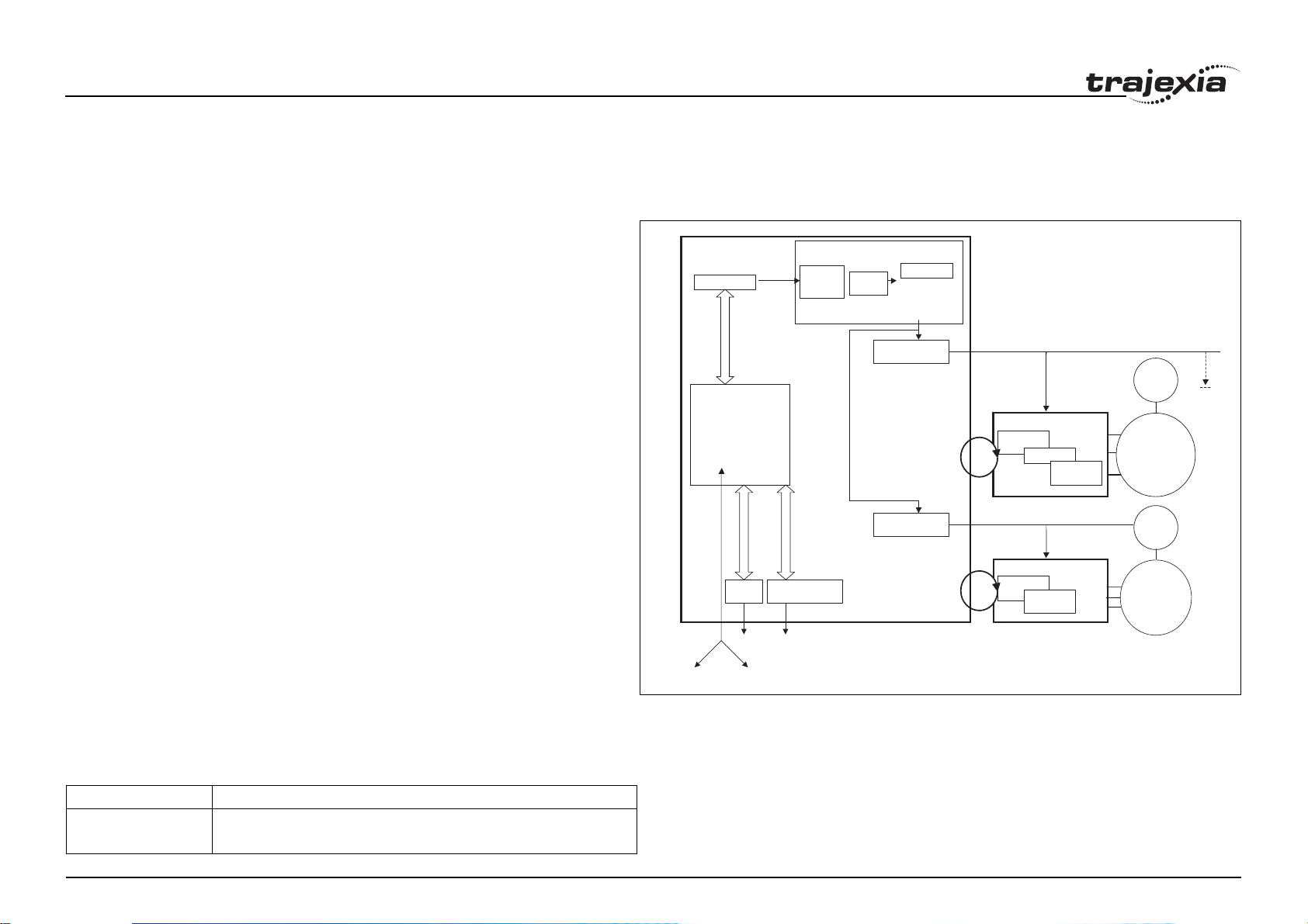
TJ1-MC__
Program Buffer
BASIC PROGRAMS
Process 1
Process 2
Process 3
…
Process 14
Comms
MC I/O
Ethernet
FINS
Ethernet
BUILT-IN TJ1-ML16
Via
Buffer &
Buffer &
profile
profile
gererator
gererator
-
TJ1 PRT
Profibus
AXIS CONTROL LOOP
Position
Position
Loop
Loop
-
TJ1 ML__
-
TJ1 FL02
AXIS TYPE
AXIS TYPE
AXIS TYPE
fig. 1
Servo Driver
Position
Position
Loop
Loop
Speed Loop
Speed Loop
Servo Driver
Speed Loop
Torque
Loop
Torque
Torque
Loop
Loop
ENC
All othe
Servo
Drivers
MOTOR
ENC
MOTOR
CPU tasks
The operations executed in each CPU task are:
CPU task Operation
Revision 5.0
First CPU task Motion Sequence
Low priority process
HARDWARE REFERENCE MANUAL 7
Page 13

System philosophy
CPU task Operation
Second CPU task High priority process
Third CPU task Motion Sequence (only if SERVO_PERIOD=0.5ms)
LED Update
High priority process
Fourth CPU task External Communications
Program
A program is a piece of BASIC code.
Process
Is a program in execution with a certain priority assigned. Process 0 to 12
are Low priority processes and Process 13 and 14 are High priority
processes. First the process priority, High or Low, and then the process
number, from high to low, will define to which CPU task the process will be
assigned.
2.2 Motion control concepts
The TJ1-MC__ offers these types of positioning control operations:
1. Point-to-Point (PTP) control
2. Continuous Path (CP) control
3. Electronic Gearing (EG) control.
This section introduces some of the commands and parameters used in the
BASIC programming of the motion control application.
Coordinate system
Positioning operations performed by the TJ1-MC__ are based on an axis
coordinate system. The TJ1-MC__ converts the position data from either the
connected Servo Driver or the connected encoder into an internal absolute
coordinate system.
Revision 5.0
The engineering unit that specifies the distances of travelling can be freely
defined for each axis separately. The conversion is performed through the
use of the unit conversion factor, which is defined by the UNITS axis
HARDWARE REFERENCE MANUAL 8
Page 14
System philosophy
parameter. The origin point of the coordinate system can be determined
using the DEFPOS command. This command re-defines the current position
to zero or any other value.
A move is defined in either absolute or relative terms. An absolute move
takes the axis (A) to a specific predefined position with respect to the origin
point. A relative move takes the axis from the current position to a position
that is defined relative to this current position. The figure shows an example
of relative (command MOVE) and absolute (command MOVEABS) linear
moves.
2.2.1 PTP control
In point-to-point positioning, each axis is moved independently of the other
axis. The TJ1-MC__ supports the following operations:
• Relative move
• Absolute move
• Continuous move forward
• Continuous move reverse.
MOVE(30)
0
fig. 2
MOVEABS(30)
MOVE(60)
MOVEABS(50)
MOVE(50)
50 100
A
Revision 5.0
HARDWARE REFERENCE MANUAL 9
Page 15
System philosophy
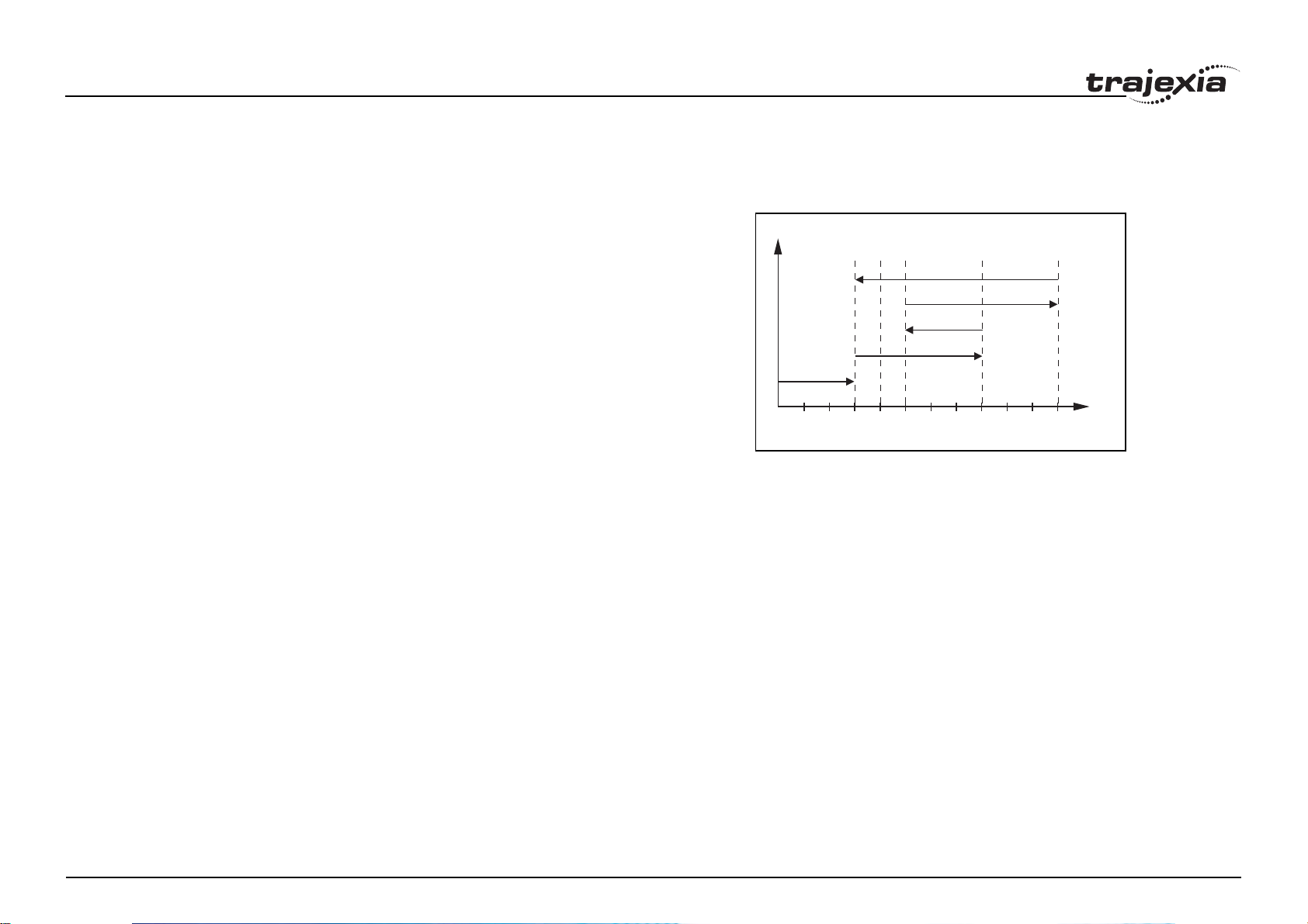
Relative and absolute moves
To move a single axis either the command MOVE for a relative move or the
command MOVEABS for an absolute move is used. Each axis has its own
move characteristics, which are defined by the axis parameters.
Suppose a control program is executed to move from the origin to an axis
no. 0 (A) coordinate of 100 and axis no. 1 (B) coordinate of 50. If the speed
parameter is set to be the same for both axes and the acceleration and
deceleration rate are set sufficiently high, the movements for axis 0 and axis
1 will be as shown in the figure.
At start, both the axis 0 and axis 1 moves to a coordinate of 50 over the
same duration of time. At this point, axis 1 stops and axis 0 continues to
move to a coordinate of 100.
The move of a certain axis is determined by the axis parameters. Some
relevant parameters are:
/i
Parameter Description
UNITS Unit conversion factor
ACCEL Acceleration rate of an axis in units/s
DECEL Deceleration rate of an axis in units/s
SPEED Demand speed of an axis in units/s
2
2
2
50
B
fig. 3
MOVEABS(100) AXIS(0)
MOVEABS(50) AXIS(1)
0
50
100
A
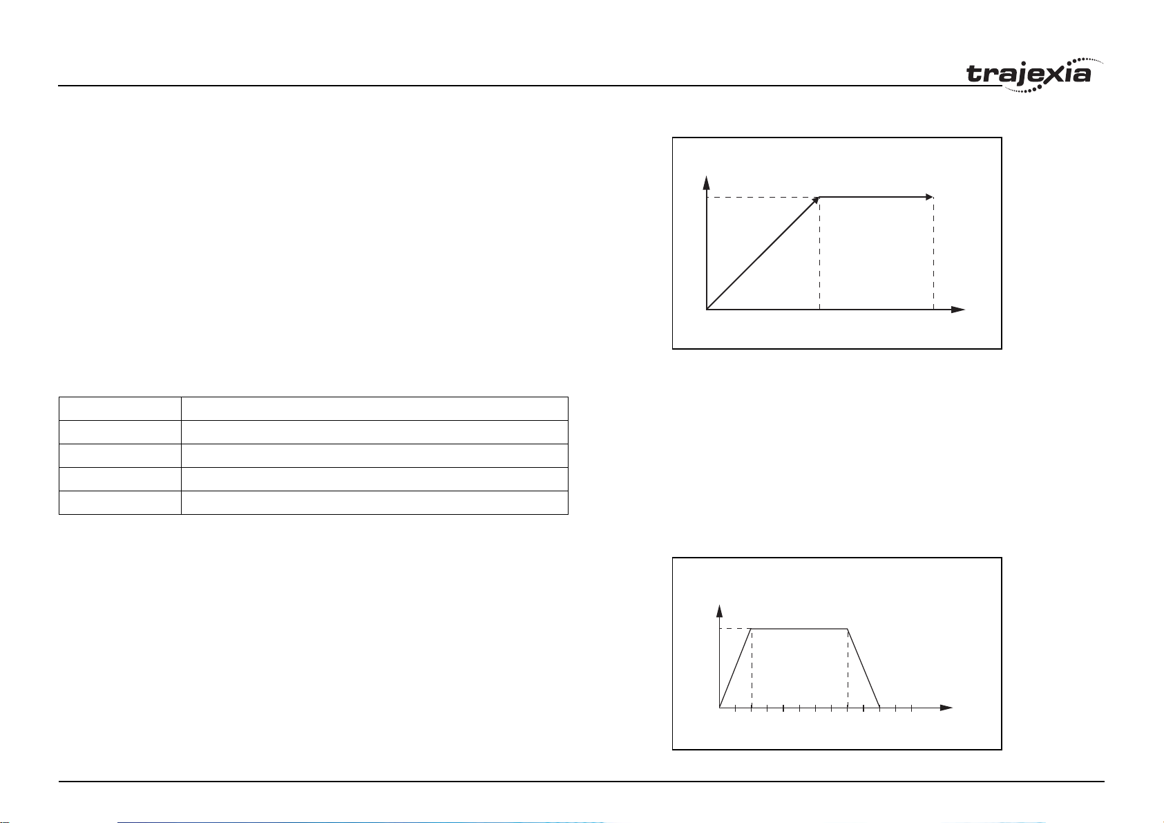
Defining moves
The speed profile in this figure shows a simple MOVE operation. Axis A is
fig. 4
the time, axis B is the speed. The UNITS parameter for this axis has been
defined for example as meters. The required maximum speed has been set
to 10 m/s. In order to reach this speed in one second and also to decelerate
to zero speed again in one second, both the acceleration as the deceleration
rate have been set to 10 m/s
2
. The total distance travelled is the sum of
10
B
ACCEL=10
DECEL=10
SPEED=10
MOVE(40)
distances travelled during the acceleration, constant speed and deceleration
segments. Suppose the distance moved by the MOVE command is 40 m,
the speed profile is given by the figure.
Revision 5.0
0
123 456
HARDWARE REFERENCE MANUAL 10
A
Page 16
System philosophy
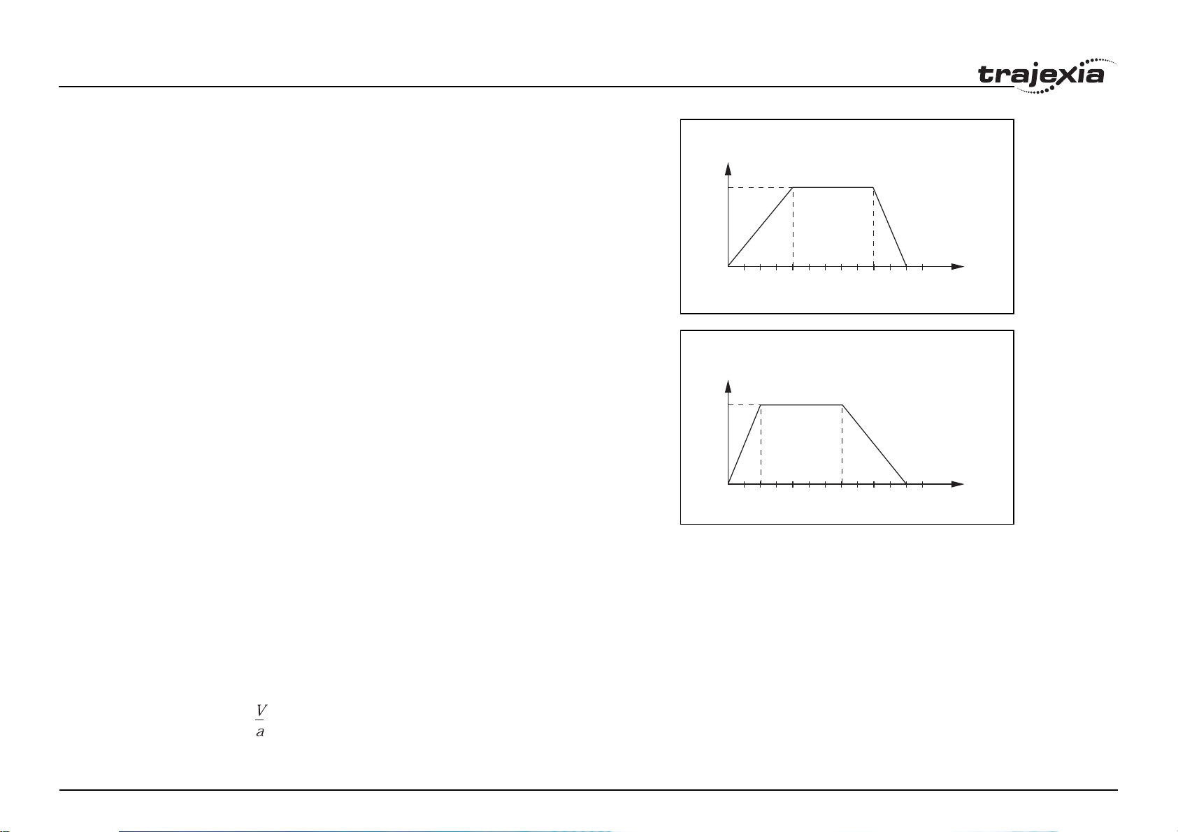
The two speed profiles in these figures show the same movement with an
acceleration time respectively a deceleration time of 2 seconds. Again, Axis
A is the time, axis B is the speed.
10
10
fig. 5
B
0
123 456
fig. 6
B
0
123 456
ACCEL=5
DECEL=10
SPEED=10
MOVE(40)
A
ACCEL=10
DECEL=5
SPEED=10
MOVE(40)
A
Move calculations
The following equations are used to calculate the total time for the motion of
the axes.
• The moved distance for the MOVE command is D.
• The demand speed is V.
• The acceleration rate is a.
• The deceleration rate is d.
/i
Revision 5.0
Acceleration time =
HARDWARE REFERENCE MANUAL 11
Page 17

System philosophy
Acceleration distance =
Deceleration time =
Deceleration distance =
Constant speed distance =
To tal tim e =
Continuous moves
The FORWARD and REVERSE commands can be used to start a
continuous movement with constant speed on a certain axis. The
FORWARD command moves the axis in positive direction and the
REVERSE command in negative direction. For these commands also the
axis parameters ACCEL and SPEED apply to specify the acceleration rate
and demand speed.
Both movements can be cancelled by using either the CANCEL or
RAPIDSTOP command. The CANCEL command cancels the move for one
axis and RAPIDSTOP cancels moves on all axes. The deceleration rate is
set by DECEL.
2.2.2 CP control
Continuous Path control enables to control a specified path between the
start and end position of a movement for one or multiple axes. The TJ1MC__ supports the following operations:
• Linear interpolation
Revision 5.0
• Circular interpolation
• CAM control.
HARDWARE REFERENCE MANUAL 12
Page 18

System philosophy
Linear interpolation
In applications it can be required for a set of motors to perform a move
operation from one position to another in a straight line. Linearly interpolated
moves can take place among several axes. The commands MOVE and
MOVEABS are also used for the linear interpolation. In this case the
commands will have multiple arguments to specify the relative or absolute
move for each axis.
Consider the three axis move in a 3-dimensional plane in the figure. It
corresponds to the MOVE(50,50,50) command. The speed profile of the
motion along the path is given in the diagram. The three parameters
SPEED, ACCEL and DECEL that determine the multi axis movement are
taken from the corresponding parameters of the base axis. The MOVE
command computes the various components of speed demand per axis.
A is the time axis, B is the speed axis.
fig. 7
2
1
3
B
A
Revision 5.0
HARDWARE REFERENCE MANUAL 13
Page 19
System philosophy
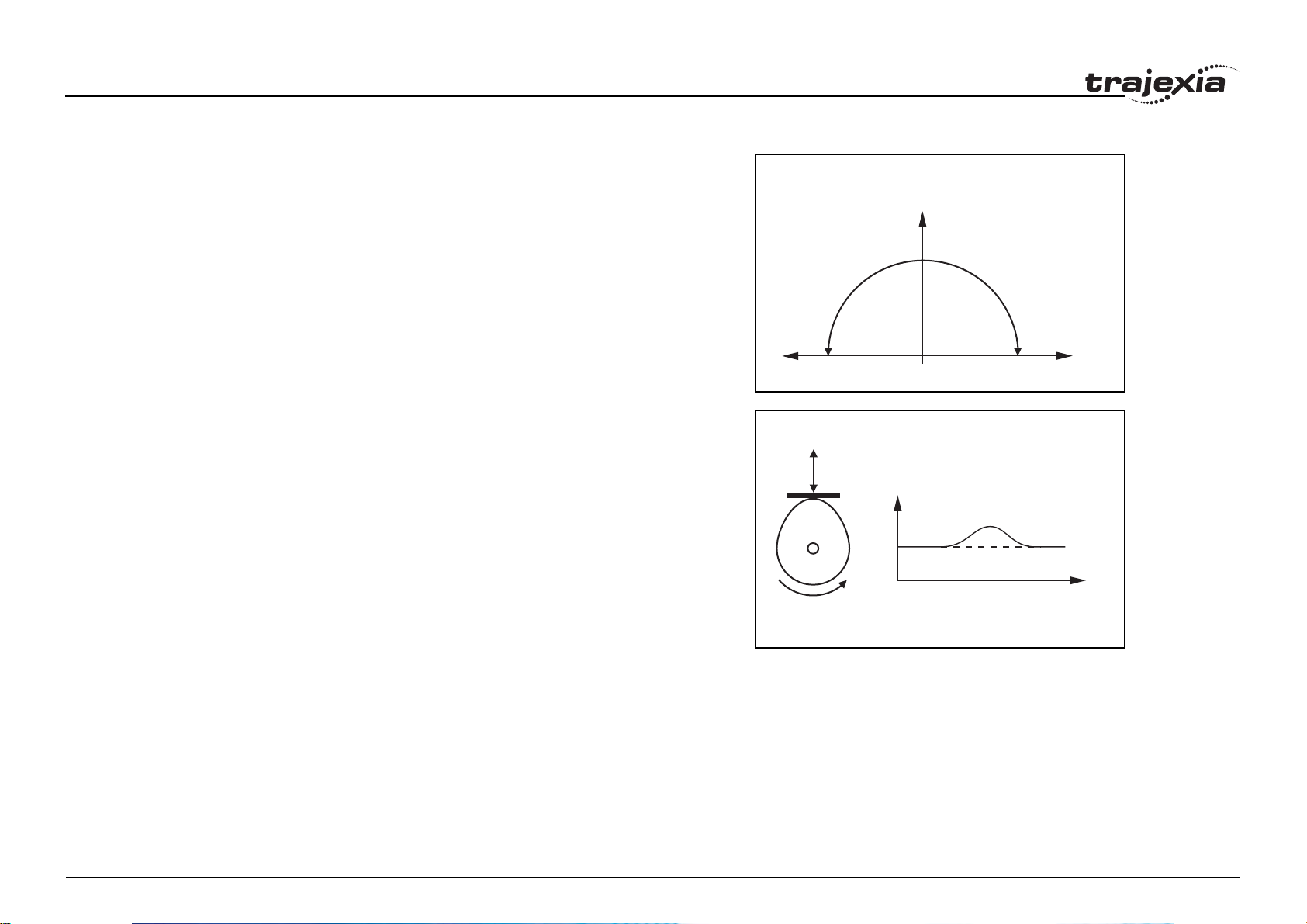
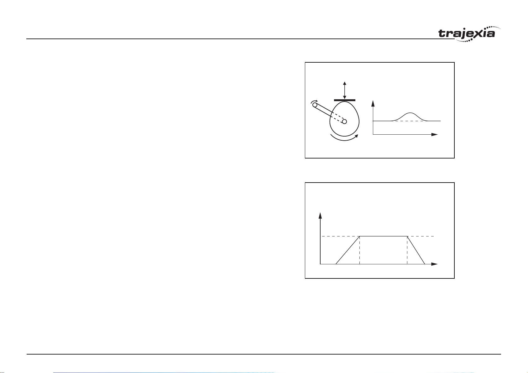
Circular interpolation
It may be required that a tool travels from the starting point to the end point
in an arc of a circle. In this instance the motion of two axes is related via a
circular interpolated move using the MOVECIRC command.
Consider the diagram in the figure. It corresponds to the MOVECIRC(-
100,0,-50,0,0) command. The centre point and desired end point of the
trajectory relative to the start point and the direction of movement are
specified. The MOVECIRC command computes the radius and the angle of
rotation. Like the linearly interpolated MOVE command, the ACCEL, DECEL
and SPEED variables associated with the base axis determine the speed
profile along the circular move.
fig. 8
50
CAM control
Additional to the standard move profiles the TJ1-MC__ also provides a way
to define a position profile for the axis to move. The CAM command moves
an axis according to position values stored in the TJ1-MC__ Table array.
The speed of travelling through the profile is determined by the axis
parameters of the axis.
The figure corresponds to the command CAM(0,99,100,20). A is the time
axis, B is the position axis.
2.2.3 EG control
Electronic Gearing control allows you to create a direct gearbox link or a
linked move between two axes. The MC Unit supports the following
operations.
• Electronic gearbox
•Linked CAM
Revision 5.0
• Linked move
• Adding axes
-50
050
fig. 9
B
A
HARDWARE REFERENCE MANUAL 14
Page 20
System philosophy
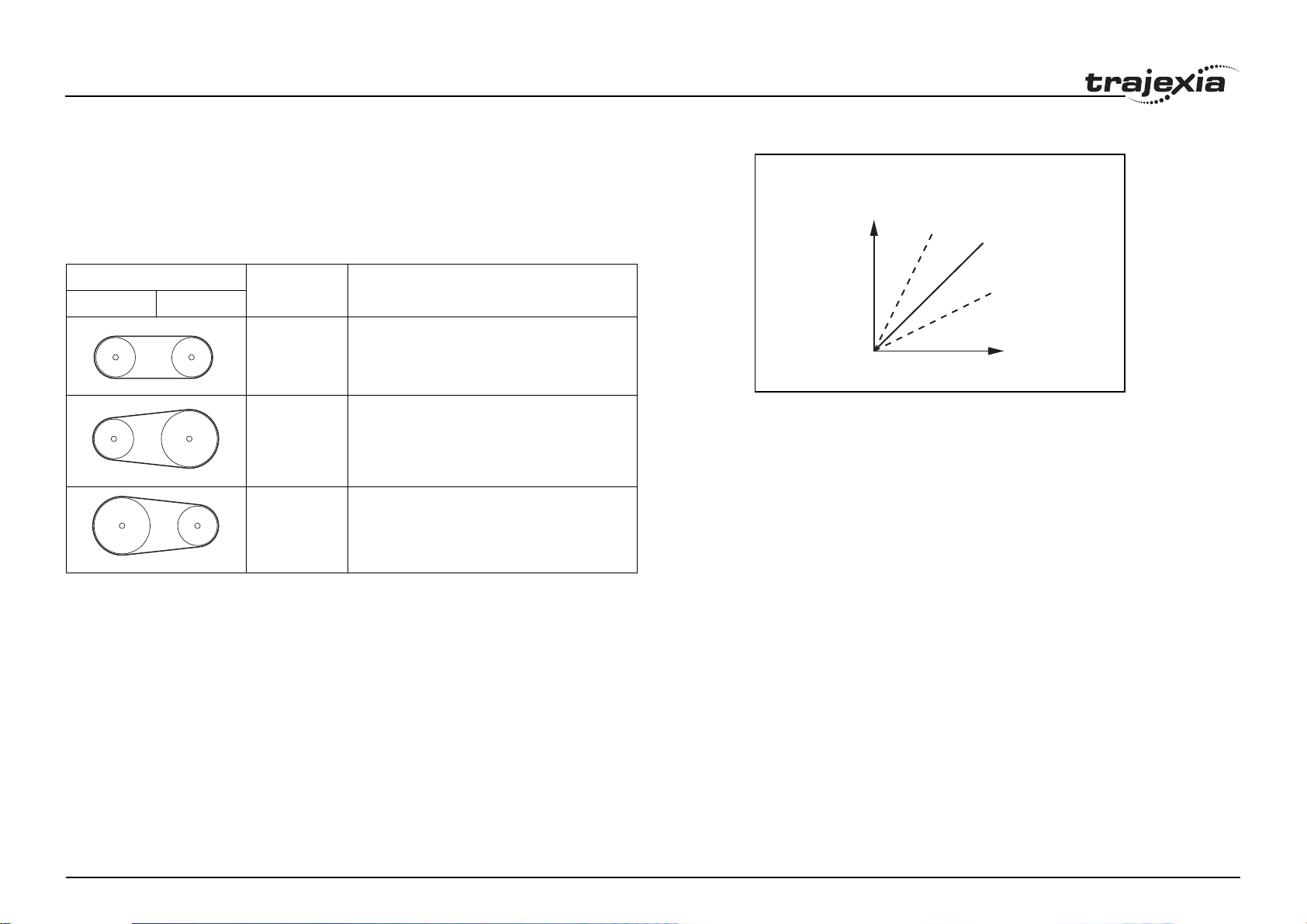
Electronic gearbox
The TJ1-MC__ is able to have a gearbox link from one axis to another as if
there is a physical gearbox connecting them. This can be done using the
CONNECT command in the program. In the command the ratio and the axis
to link to are specified.
In the figure, A is the Master axis, and B is the CONNECT axis.
/i
B
fig. 10
2:1
1:1
Axes Ratio CONNECT command
0 1
1:1 CONNECT(1,0) AXIS(1)
2:1 CONNECT(2,0) AXIS(1)
1:2 CONNECT(0.5,0) AXIS(1)
1:2
A
Revision 5.0
HARDWARE REFERENCE MANUAL 15
Page 21
System philosophy
Linked CAM control
Next to the standard CAM profiling tool the TJ1-MC__ also provides a tool to
link the CAM profile to another axis. The command to create the link is called
CAMBOX. The travelling speed through the profile is not determined by the
axis parameters of the axis but by the position of the linked axis. This is like
connecting two axes through a cam.
In the figure, A is the Master axis (0) position, and B is the CAMBOX Axis (1)
position.
Linked move
The MOVELINK command provides a way to link a specified move to a
master axis. The move is divided into an acceleration, deceleration and
constant speed part and they are specified in master link distances. This can
be particularly useful for synchronizing two axes for a fixed period.
The labels in the figure are:
A. Time axis.
B. Speed axis.
C. Master axis (1).
D. Synchronized.
E. MOVELINK axis (0).
fig. 11
B
A
fig. 12
B
DC
E
A
Revision 5.0
HARDWARE REFERENCE MANUAL 16
Page 22
System philosophy
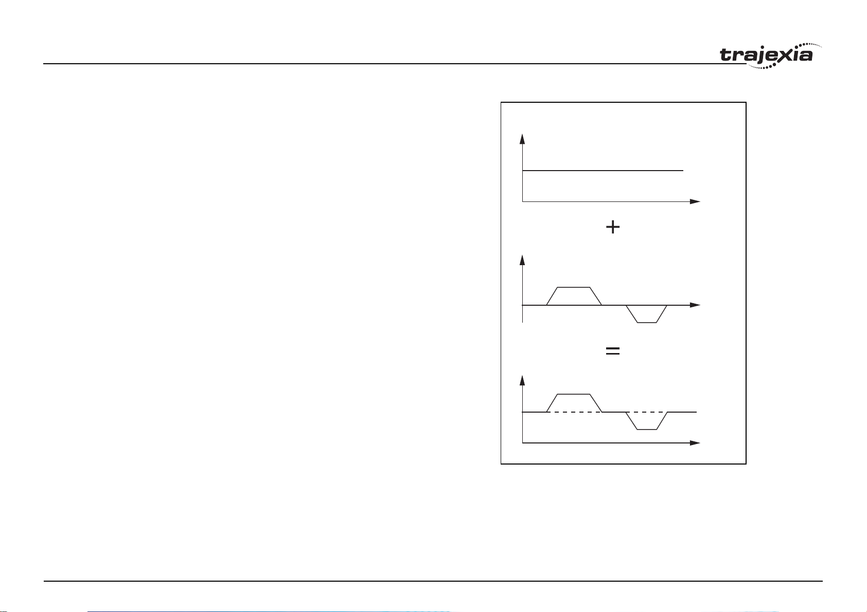
Adding axes
It is very useful to be able to add all movements of one axis to another. One
possible application is for instance changing the offset between two axes
linked by an electronic gearbox. The TJ1-MC__ provides this possibility by
using the ADDAX command. The movements of the linked axis will consists
of all movements of the actual axis plus the additional movements of the
master axis.
In the figure, A is the time axis and B is the speed axis.
B
B
fig. 13
BASE(0)
ADDAX(2)
FORWARD
MOVE(100) AXIS(2)
MOVE(-60) AXIS(2)
A
A
B
A
Revision 5.0
HARDWARE REFERENCE MANUAL 17
Page 23

System philosophy
2.2.4 Other operations
Cancelling moves
In normal operation or in case of emergency it can be necessary to cancel
the current movement from the buffers. When the CANCEL or RAPIDSTOP
commands are given, the selected axis respectively all axes will cancel their
current move.
Origin search
The encoder feedback for controlling the position of the motor is
incremental. This means that all movement must be defined with respect to
an origin point. The DATUM command is used to set up a procedure
whereby the TJ1-MC__ goes through a sequence and searches for the
origin based on digital inputs and/or Z-marker from the encoder signal.
Print registration
The TJ1-MC__ can capture the position of an axis in a register when an
event occurs. The event is referred to as the print registration input. On the
rising or falling edge of an input signal, which is either the Z-marker or an
input, the TJ1-MC__ captures the position of an axis in hardware. This
position can then be used to correct possible error between the actual
position and the desired position. The print registration is set up by using the
REGIST command.
The position is captured in hardware, and therefore there is no software
overhead and no interrupt service routines, eliminating the need to deal with
the associated timing issues.
Revision 5.0
HARDWARE REFERENCE MANUAL 18
Page 24
System philosophy
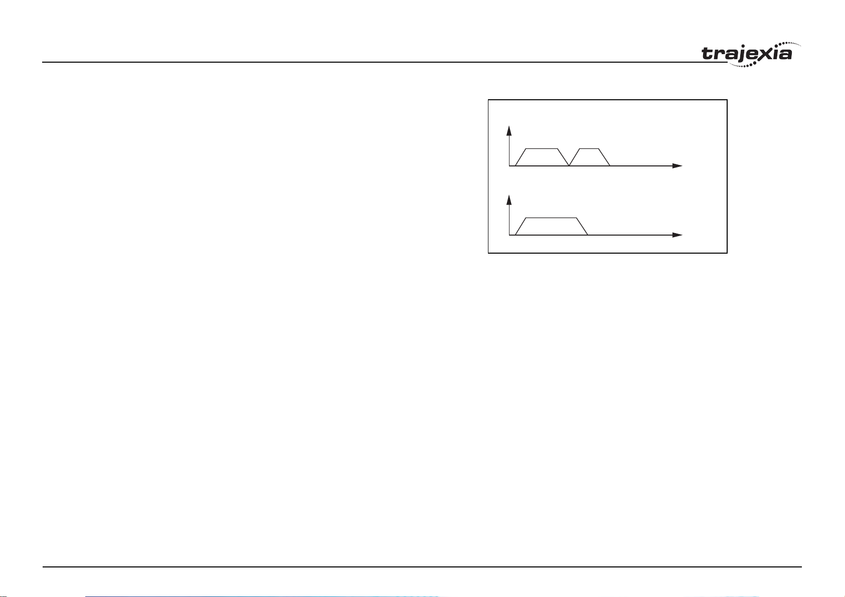
Merging moves
If the MERGE axis parameter is set to 1, a movement is always followed by
a subsequent movement without stopping. The figures show the transitions
of two moves with MERGE value 0 and value 1.
In the figure, A is the time axis and B is the speed axis.
fig. 14
B
MERGE=0
Jogging
Jogging moves the axes at a constant speed forward or reverse by manual
operation of the digital inputs. Different speeds are also selectable by input.
Refer to the FWD_JOG, REV_JOG and FAST_JOG axis parameters.
2.3 Servo system principles
The servo system used by and the internal operation of the TJ1-MC__ are
briefly described in this section.
2.3.1 Semi-closed loop system
The servo system of the TJ1-MC__ uses a semi-closed or inferred closed
loop system. This system detects actual machine movements by the rotation
of the motor in relation to a target value. It calculates the error between the
target value and actual movement, and reduces the error through feedback.
A
B
MERGE=1
A
Revision 5.0
HARDWARE REFERENCE MANUAL 19
Page 25
System philosophy
2.3.2 Internal operation of the TJ1-MC__
Inferred closed loop systems occupy the mainstream in modern servo
systems applied to positioning devices for industrial applications. The figure
shows the basic principle of the servo system as used in the TJ1-MC__.
1. The TJ1-MC__ performs actual position control. The main input of the
controller is the Following Error, which is the calculated difference
between the demand position and the actual measured position.
2. The Position Controller calculates the required speed reference output
determined by the Following Error and possibly the demanded position
and the measured position. The speed reference is provided to the
Servo Driver.
3. The Servo Driver controls the rotational speed of the servo motor
corresponding to the speed reference. The rotational speed is
proportional to the speed reference.
4. The rotary encoder generates the feedback pulses for both the speed
feedback within the Servo Driver speed loop and the position feedback
within the TJ1-MC__ position loop.
The labels in the figure are:
A. TJ1-MC__.
B. Servo system.
C. Demand position.
D. Position control.
E. Speed reference.
F. Speed control.
G. M otor.
H. Encoder.
I. Measured speed.
J. Measured position.
C
fig. 15
AB
2
1
D
E
3
F
G
4
I
H
J
2.3.3 Motion control algorithm
The servo system controls the motor by continuously adjusting the speed
Revision 5.0
reference to the Servo Driver. The speed reference is calculated by the
motion control algorithm of the TJ1-MC__, which is explained in this section.
HARDWARE REFERENCE MANUAL 20
Page 26

System philosophy
The motion control algorithm uses the demand position (A), the measured
position (D) and the Following Error (B) to determine the speed reference.
The Following Error is the difference between the demanded and measured
position. The demand position, the measured position and the Following
Error are represented by the axis parameters MPOS, DPOS and FE. Five
gain values have been implemented for the user to be able to configure the
correct control operation for each application.
C is the output signal.
• Proportional gain
The proportional gain K
creates an output Op that is proportional to the
p
Following Error E.
O
= Kp · E
p
All practical systems use proportional gain. For many just using this gain
parameter alone is sufficient. The proportional gain axis parameter is
called P_GAIN.
• Integral gain
The integral gain K
creates an output Oi that is proportional to the sum
i
of the Following Errors that have occurred during the system operation.
O
= Ki · ΣE
i
Integral gain can cause overshoot and so is usually used only on
systems working at constant speed or with slow accelerations. The
integral gain axis parameter is called I_GAIN.
• Derivative gain
The derivative gain K
produces an output Od that is proportional to the
d
change in the Following Error E and speeds up the response to changes
in error while maintaining the same relative stability.
O
= Kd · ∆E
d
Derivative gain may create a smoother response. High values may lead
to oscillation. The derivative gain axis parameter is called D_GAIN.
• Output speed gain
The output speed gain K
the change in the measured position P
O
= Kov · ∆P
ov
Revision 5.0
m
produces an output Oov that is proportional to
ov
and increases system damping.
m
fig. 16
∑
K
vff
K
p
AB C
∑
K
i
∆
K
d
∆
K
ov
D
HARDWARE REFERENCE MANUAL 21
Page 27
System philosophy
The output speed gain can be useful for smoothing motions but will
generate high Following Errors. The output speed gain axis parameter is
called OV_GAIN.
• Speed feed forward gain
The speed feedforward gain K
proportional to the change in demand position P
produces an output O
vff
and minimizes the
d
that is
vff
Following Error at high speed.
O
= K
vff
· ∆P
d
vff
The parameter can be set to minimise the Following Error at a constant
machine speed after other gains have been set. The speed feed forward
gain axis parameter is called VFF_GAIN.
The default settings are given in the table along with the resulting profiles.
Fractional values are allowed for gain settings.
/i
Gain Default value
Proportional gain 0.1
Integral gain 0.0
Derivative gain 0.0
Output speed gain 0.0
Speed feedforward gain 0.0
2.4 Trajexia system architecture
The system architecture of the Trajexia is dependant upon these
concepts:
• Program control
• Motion Sequence
• Motion buffers
• Communication
• Peripherals
Revision 5.0
These concepts depend upon the value set in the SERVO_PERIOD
parameter. The relationship between the value of SERVO_PERIOD and the
different concepts of the system architecture are describes as follows.
2.4.1 Program control
Programs make the system work in a defined way. The programs are written
in a language similar to BASIC and control the application of the axes and
modules. 14 Programs can be executed in parallel. The programs can be set
to run at system power-up, started and stopped from other programs and
executed from Trajexia Tools.
Programs execute commands to move the axes, control inputs and outputs
and make communication via BASIC commands.
2.4.2 Motion sequence
The motion sequence controls the position of all 16 axes with the actions as
follows:
• Reading the Motion buffer
• Reading the current Measured Position (MPOS)
• Calculating the next Demanded Position (DPOS)
• Executing the Position loop
• Sending the Axis reference
• Error handling
2.4.3 Motion buffers
Motion buffers are the link between the BASIC commands and the Axis
control loop. When a BASIC motion command is executed, the command is
stored in one of the buffers. During the next motion sequence, the profile
generator executes the movement according to the information in the buffer.
When the movement is finished, the motion command is removed from the
buffer.
2.4.4 Communication
All communication is carried out in the forth CPU task. A set of BASIC
communication commands are used to configure the communications.
When the Trajexia is a communication slave (as in the PROFIBUS
communication) it is only necessary to configure the communication in an
HARDWARE REFERENCE MANUAL 22
Page 28
System philosophy
initial task. The values are exchanged from the configured global variables in
a transparent way. When the Trajexia is a communications master, the
BASIC communication commands are used to write and read.
2.4.5 Peripherals
All inputs and outputs are used with the set of parameters (IN, OP, AIN,
AOUT). The inputs and outputs are automatically detected and mapped in
Trajexia. Inverters are considered a peripheral device and have a set of
BASIC commands to control them. Various MECHATROLINK-II input and
output modules can be connected to a TJ1-ML__ unit.
2.5 Cycle time
All processes in the Trajexia system are based on the cycle time. The cycle
time is divided into four CPU tasks:
•250µs time intervals for a SERVO_PERIOD of 0.5 and 1.0ms
•500µs time intervals for a SERVO_PERIOD of 2.0ms
The processes that can be carried out in each time interval depends on the
SERVO_PERIOD that is set.
The operations executed in each CPU task are:
CPU task Operation
First CPU task Motion Sequence
Low priority process
Second CPU task High priority process
Third CPU task
Fourth CPU task External Communications
Revision 5.0
Note
1
Motion Sequence (only if SERVO_PERIOD=0.5ms)
LED Update.
High priority process
The Motion sequence execution depends on setting of the
SERVO_PERIOD parameter.
250µs
1
500 µs
1
fig. 17
2
Cycle time = 1ms
fig. 18
2
Cycle time = 2 ms
3
3
4
4
HARDWARE REFERENCE MANUAL 23
Page 29

System philosophy
2.5.1 Servo period
The SERVO_PERIOD can be set at 0.5, 1 or 2ms. The processes that take
place within the cycle time depend on the setting of the SERVO_PERIOD
parameter. The SERVO_PERIOD parameter is a Trajexia parameter that
must be set according to the system configuration.
The factory setting is 1ms (SERVO_PERIOD=1000). A change is set only
after a restart of the TJ1-MC__.
Note
Only the Sigma-III Servo Driver and the Sigma-V Servo Driver
support the 0.5 ms transmission cycle.
Example 1
The SERVO_PERIOD has a value of 0.5ms and the motion sequence is
executed every 0.5ms.
CPU task 1
CPU task 2
fig. 19
Motion sequence
Low priority task (0,1,2,3...)
High priority task (13,14)
CPU task 3
CPU task 4
Revision 5.0
Motion sequence
LED refresh
High priority task (13,14)
Communication
1ms
HARDWARE REFERENCE MANUAL 24
Page 30
System philosophy
Example 2
The SERVO_PERIOD has a value of 1ms and the motion sequence is
executed every 1ms. As the motion sequence is not executed during CPU
task 3, there is more time for the program execution. High priority programs
run faster.
CPU task 1
CPU task 2
fig. 20
Motion sequence
Low priority task (0,1,2,3...)
High priority task (13,14)
Example 3
The SERVO_PERIOD has a value of 2ms and the motion sequence is
executed every 2.0ms.
Servo period rules
The number of axes and MECHATROLINK-II devices in the Trajexia system
determines the value of the SERVO_PERIOD system parameter.
There are 3 types of MECHATROLINK-II devices that are supported by the
TJ1-MC__ units:
• Servo Drivers
The TJ1-MC__ considers Servo Drivers as axes.
• Inverters
The TJ1-MC__ does not consider Inverters as axes.
• I/O units and slice bus couplers
The TJ1-MC__ does not consider I/O units (analog and digital, counter
and pulse) and slice bus couplers as axes.
CPU task 3
CPU task 4
CPU task 1
CPU task 2
CPU task 3
CPU task 4
LED refresh
High priority task (13,14)
Communication
fig. 21
Motion sequence
Low priority task (0,1,2,3...)
High priority task (13,14)
LED refresh
High priority task (13,14)
Communication
1ms
2ms
You must obey the most restrictive rules when you set the SERVO_PERIOD
parameter. An incorrect value of the SERVO_PERIOD parameter results in
an incorrect detection of the MECHATROLINK-II devices.
Revision 5.0
The most restrictive rules are given in the tables below. For each unit the
table lists the maximum number of devices the unit can control at the given
SERVO_PERIOD setting.
HARDWARE REFERENCE MANUAL 25
Page 31

System philosophy
/i
SERVO_PERIOD TJ1-MC16 TJ1-MC04 TJ1-ML16 TJ1-ML04
0.5 ms 8 axes 5 axes 4 devices 4 devices
4 non-axis
devices
1.0 ms 16 axes 5 axes 8 devices 4 devices
4 non-axis
devices
8 non-axis
devices
2.0 ms 16 axes 5 axes 16 devices 4 devices
8 non-axis
devices
8 non-axis
devices
8 non-axis
devices
Configuration examples
Example 1
• 1x TJ1-MC__
• 1x TJ1-ML__
• 3x Sigma-II Servo Driver
• SERVO_PERIOD = 1ms
TJ1-MC__ Supports 0.5ms SERVO_PERIOD with 3 axes.
TJ1-MC__ Supports 0.5ms SERVO_PERIOD with 3 devices.
Sigma-II supports 1ms SERVO_PERIOD. This is the limiting factor.
Address
43
fig. 22
Servo Driver
Address44Address
45
Terminator
Revision 5.0
Axis 2 Axis 3 Axis 4
HARDWARE REFERENCE MANUAL 26
Page 32

System philosophy
Example 2
• 1x TJ1-MC16
• 2x TJ1-ML16
• 16x Sigma-II Servo Driver
• SERVO_PERIOD = 1ms
TJ1-MC16 supports 1ms SERVO_PERIOD with 16 axes.
TJ1-ML16 supports 1ms SERVO_PERIOD with 8 devices.
Sigma-II supports 1ms SERVO_PERIOD.
fig. 23
Servo Drive
Address 41Address 42Address 43Address 44Address 45Address 46Address 47Address
48
Terminator
Axis 0
Address
49
Axis 8
Revision 5.0
Axis 1
Address 4AAddress 4BAddress 4CAddress 4DAddress 4EAddress 4FAddress
Axis 9
Axis 2
Axis 10
Axis 3
Axis 11
Axis 4
Axis 12
Axis 5
Axis 13
Axis 6
Axis 14
Axis 7
50
Axis 15
Terminator
HARDWARE REFERENCE MANUAL 27
Page 33

System philosophy
Example 3
• 1x TJ1-MC16
• 1x TJ1-ML16
• 8x Sigma-II Servo Driver
• 1x F7Z Inverter with SI-T interface
• 3x MECHATROLINK-II I/Os
• SERVO_PERIOD = 2.0ms
fig. 24
TJ1-ML16 supports 2.0ms SERVO_PERIOD with 12 devices. This is the
limiting factor.
Sigma-II supports 1.0ms SERVO_PERIOD.
SI-T supports 1ms.
MECHATROLINK-II I/Os support 1.0ms.
Example 4
• 1x TJ1-MC16
• 1x TJ1-ML16
• 2x TJ1-FL02
• 1x TJ1-PRT (does not influence in the SERVO_PERIOD)
• 5x Sigma-II Servo Driver
• SERVO_PERIOD = 1.0ms
TJ1-MC16 supports 1.0ms SERVO_PERIOD with 9 axes (5
MECHATROLINK-II servo axes and 4 TJ1-FL02 axes)
TJ1-ML16 supports 1.0ms SERVO_PERIOD with 5 devices
TJ1-FL02 supports 0.5ms SERVO_PERIOD (2 axes each module)
Sigma-II supports 1.0ms SERVO_PERIOD.
Address
21
Address
0 31 32 95 96 159 160
I/O Memory Allocations
Address 62Address
61
63
Address 41Address 42Address 43Address 44Address 45Address 46Address 47Address
fig. 25
Axis 8Axis 7 Axis 1Axis 0
Address43Address44Address45Address46Address
47
48
Revision 5.0
Axis 2 Axis 3 Axis 4 Axis 5 Axis 6
HARDWARE REFERENCE MANUAL 28
Page 34

System philosophy
2.6 Program control and multi-tasking
The Trajexia system has program, processes and multi tasking control.
2.6.1 Program control
The Trajexia system can control 14 processes that are written as BASIC
programs. When the program is set to run, the program is executed.
Processes 1 to 12 are low priority, 13 and 14 are high priority.
2.6.2 Processes
The low-priority process 0 is reserved for the "Terminal Window" of Trajexia
Tools. This terminal window is used to write direct BASIC commands to the
TJ1-MC__ independent to other programs. These commands are executed
after you press the Enter button.
2.6.3 Multi-tasking
Each cycle time is divided into 4 time slices called CPU tasks. Processes run
fig. 26
in the first 3 CPU tasks according to the priority of the process.
Motion sequence and low-priority processes (A) are executed in the Low
Task (LT) period.
LT HT #1 HT #2
COMS.
High priority processes (B) are executed in the high Task (HT) periods.
Cycle time
External communication that are not related to the motion network are
updated in the communications (COMS) period in the fourth CPU task.
A
fig. 27
B
Trajexia can control up to 14 programs at the same time.
In contrast to low priority processes, a high priority process is always
available for execution during two of the four CPU tasks. The high-priority
tasks are executed faster than the low-priority tasks, it is that they have more
time available for their execution. All the low-priority tasks must share one
slot of time and the high-priority task have their own two slots of time.
Revision 5.0
HARDWARE REFERENCE MANUAL 29
LT HT #1 HT #2
Cycle time
COMS.
Page 35

System philosophy
2.6.4 Multi-tasking example
In the example 1, there are two high-priority processes, 13 and 14. The two
HT periods are reserved for these processes, one for processes 13 and one
for processes 14. The low-priority processes 3, 2, 1 and 0 are executed in
the LT period, one process per Cycle time here set to 1.0ms.
In the middle example, there is only one high-priority process, 14. Both HT
periods are reserved for this process. The low-priority processes, 3, 2, 1 and
0 are executed in the LT period, one process per cycle time.
In the lower example, there are no high-priority processes. Therefore, the
HT periods can be used for the low-priority processes. The LT period is also
used for the low-priority processes.
2.7 Motion sequence and axes
Motion sequence is the part of the TJ1-MC__ that controls the axes. The
actual way that the motion sequence operates depends on the axis type.
The axis type can be set and read by the parameter ATYPE. At start-up the
Trajexia system automatically detects the configuration of the axes.
• The default value for the parameter ATYPE for MECHATROLINK-II axes
is 41 (MECHATROLINK-II speed).
• The default value for the parameter ATYPE for the TJ1-FL02 axes is 44
(Servo axis with an incremental encoder).
fig. 28
14
10
(c/l)
1ms
1ms
141
1ms
13
1ms
14
13
1ms
140
1ms
0
(c/l)
(c/l)
3
COMS.
210
1
14
3
2
3
321
1ms
1ms
143
1ms
13
COMS.
COMS.
COMS.
2
0
(c/l)
1ms
13
14
1ms
142
1ms
32
COMS. COMS.
1
COMS. COMS.
COMS. COMS.
fig. 29
• block
•
AXIS PARAMETER
Servo Drive
COMS.
COMS.
(c/l)
All non allocated axes are set as a virtual axis. The value for the parameter
ATYP E is 0.
Every axis has the general structure as shown in fig. 29.
Revision 5.0
The motion sequence which will be executed at the beginning of each servo
period will contain the following elements:
Profile generatorProfile generator
Demanded
Demanded
position
position
Measured
Measured
position
position
Position loop
Position loop
+
+
-
Foll owing
Foll owing
error
error
command
command
Speed
Speed
OFF
ON
Speed loop
Torq ue
loop
HARDWARE REFERENCE MANUAL 30
M
E
Page 36

System philosophy
1. Transfer any moves from BASIC process buffers to motion buffers (see
section 2.8).
2. Read digital inputs.
3. Load moves. (See note.)
4. Calculate speed profile. (See note.)
5. Calculate axis positions. (See note.)
6. Execute position servo. For axis 0 this also includes the Servo Driver
communications. (See note.)
7. Update outputs.
Note
Each of these items will be performed for each axis in turn before
moving on to the next item.
2.7.1 Profile generator
The profile generator is the algorithm that calculates the demanded position
for each axis. The calculation is made every motion sequence.
The profile is generated according to the motion instructions from the BASIC
programs.
Basic Program
.........
.........
MOVE(1000)
.........
.........
fig. 30
Profile generator
Demand Position
2.7.2 Position loop
The position loop is the algorithm that makes sure that there is a minimal
deviation between the measured position (MPOS) and the demand position
(DPOS) of the same axis.
2.7.3 Axis sequence
• The motion controller applies motion commands to an axis array that is
Revision 5.0
defined with the BASE command. If the motion command concerns one
axis, it is applied to the first axis in the BASE array. If the motion
command concerns more than one axis, and makes an orthogonal
HARDWARE REFERENCE MANUAL 31
Page 37

System philosophy
move, the axes are taken from the array in the order defined by the
BASE command. For more information on the BASE command and the
definition of the axis sequence in an axis array, refer to the Trajexia
Programming Manual, chapter 3 (BASIC commands).
•If SERVO=OFF for one axis, the motion commands for that axis are
ignored.
• If the Following Error (FE) in one axis exceeds the parameter value
FELIMIT, the next action occurs:
- WDOG is set to OFF and all axes stop.
- SERVO for the axis that causes the error goes to OFF.
- The current move is cancelled and removed from the buffer.
2.7.4 Type of axis
/i
ATYPE Applicable to Name Description
0 All axes Virtual axis Internal axis with no physical output. It is the
only valid setting for non-allocated axes. That
is, those that are not MECHATROLINK-II servos or a flexible axis.
40 MECHATRO-
LINK-II Servo
Drivers con-
41 MECHATRO-
42 MECHATRO-
Revision 5.0
nected to a TJ1ML__
MECHATROLINK-II Position
LINK-II Speed
(Default)
LINK-II Torque
Position loop in the Servo Driver. TJ1-MC__
sends position reference to the Servo Driver
via MECHATROLINK-II.
Position loop in the Trajexia. TJ1-MC__ sends
speed reference to the Servo Driver via
MECHATROLINK-II.
Position loop in the Trajexia. TJ1-MC__ sends
torque reference to the Servo Driver via
MECHATROLINK-II.
HARDWARE REFERENCE MANUAL 32
Page 38

System philosophy
ATYPE Applicable to Name Description
43 External driver
connected to a
TJ1-FL02
44 Servo axis
Stepper output Pulse and direction outputs. Position loop is in
the driver. TJ1-FL02 sends pulses and receives
no feed back.
Analogue servo. Position loop is in the TJ1(Default)
Encoder
MC__. The TJ1-FL02 sends speed reference
and receives position from an incremental
encoder.
45 Encoder out-
put
The same as stepper, but with the phase differ-
ential outputs emulating an incremental
encoder.
46 Absolute Tam-
agawa
47 Absolute
EnDat
The same as servo axis but the feed back is
received from a Tamagawa absolute encoder.
The same as servo axis but the feed back is
received from an EnDat absolute encoder.
48 Absolute SSI The same as servo axis but the feed back is
received from an SSI absolute encoder.
49 ML__ Inverter as
axis
Inverters (with built-in encoder interface) are
controlled on the MECHATROLINK-II bus as
servo axes.
Virtual axis ATYPE=0
You can split a complex profile into two or more simple movements, each
assigned to a virtual axis. These movements can be added together with the
BASIC command ADDAX then assigned to a real axis.
fig. 31
Profile generator
MEASURED
POSITION
Revision 5.0
=
DEMAND
POSITION
HARDWARE REFERENCE MANUAL 33
Page 39
System philosophy
MECHATROLINK-II position ATYPE=40
With SERVO = ON, the position loop is closed in the Servo Driver. Gain
settings in the TJ1-MC__ have no effect. The position reference is sent to
the Servo Driver.
TJ1-MC__
fig. 32
TJ1-ML__ SERVO
Note
Although MPOS and FE are updated, the real value is the value in
the Servo Driver. The real Following Error can be monitored by the
DRIVE_MONITOR parameter by setting DRIVE_CONTROL = 2.
Note
The MECHATROLINK-II position ATYPE = 40 is the recom-
mended setting to obtain a higher performance of the servo motor.
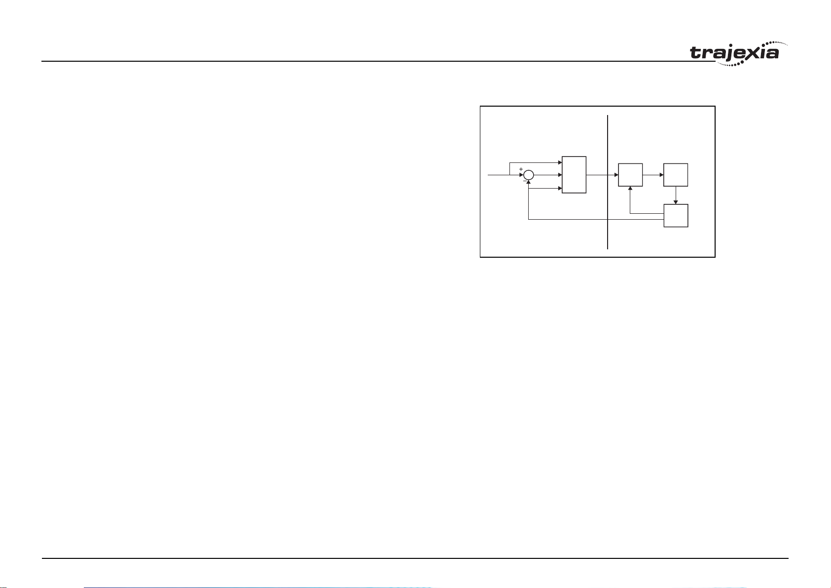
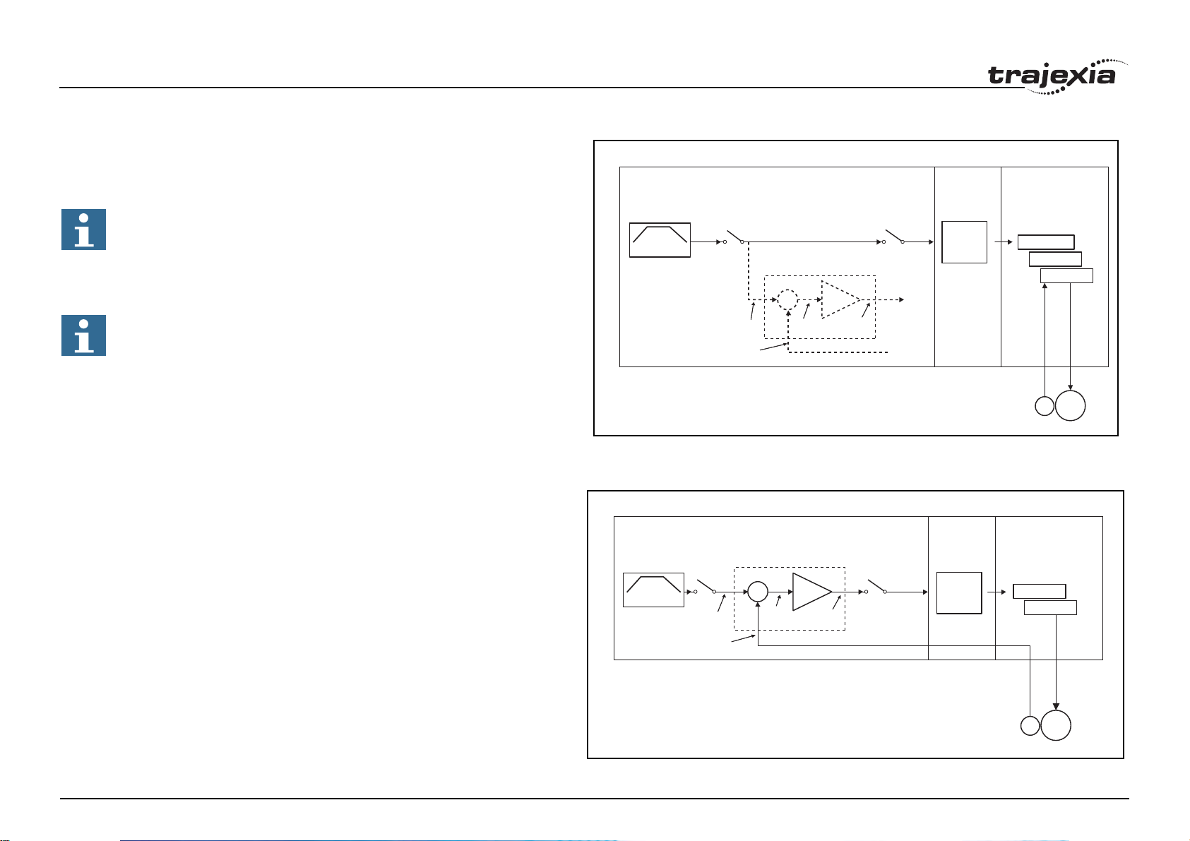
MECHATROLINK-II speed ATYPE=41
With SERVO = ON, the speed loop is closed in the TJ1-MC__.
Speed reference is sent to the Servo Driver. This setting is not
recommended, since there is one cycle delay in the loop (DPOS(n) is
compared with MPOS(n-1)).
With SERVO = OFF, the speed reference is sent via S_REF command.
0x40000000 means maximum speed of the servomotor. This is the
recommended setting.
Profile generator
Trajexia
Position Loop is
deactivated
(Gains are not
used!)
Profile generator
SERVO = OFF SERVO = OFF
Position loop
+
_
Demanded
position
Measured
position
Following
error
Speed
command
fig. 33
TJ1-MC__
Demanded
position
Measured
position
Position loop
+
_
Following
error
Speed
command
SERVO = OFF SERVO = OFF
ML-II
Position
command
TJ1-ML__
ML-II
Speed
command
Position Loop
Speed Loop
Torque Loop
E
SERVO
Speed Loop
Torque Loop
M
Revision 5.0
M
E
HARDWARE REFERENCE MANUAL 34
Page 40

System philosophy
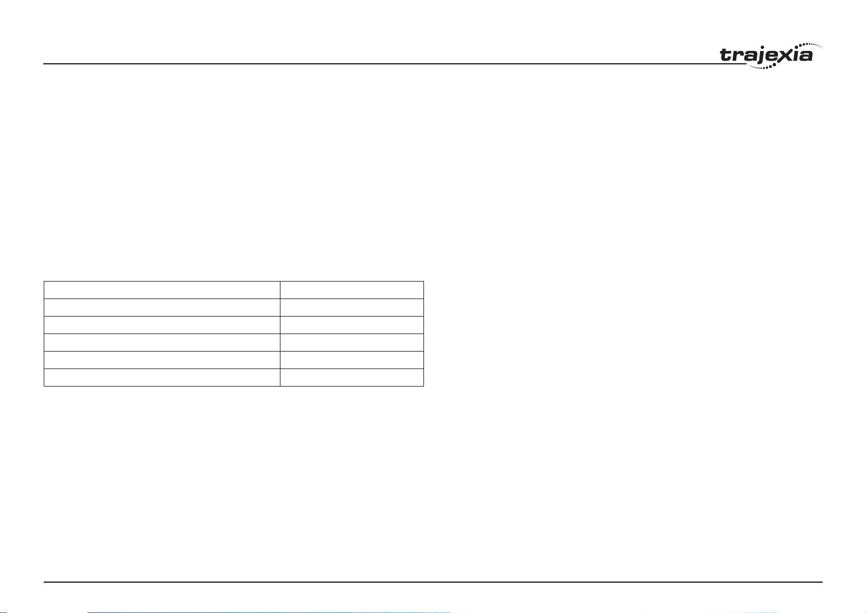
MECHATROLINK-II torque ATYPE=42
With SERVO = ON, the torque loop is closed in the TJ1-MC__. The torque
reference in the Servo Driver depends on the FE and the gain.
With SERVO = OFF, the torque reference is sent directly via the T_REF
command. 0x40000000 is the maximum torque of the servomotor.
TJ1-MC__
fig. 34
TJ1-ML__
SERVO
Note
To monitor the torque in the servo in DRIVE_MONITOR, set
DRIVE_CONTROL=11.
Stepper output ATYPE=43
The position profile is generated and the output from the system is a pulse
train and direction signal. This is useful to control a motor via pulses or as a
position reference for another motion controller.
Profile generator
Demanded
position
Measured
position
Position loop
+
_
Following
error
Torque
command
SERVO = OFF SERVO = OFF
ML-II
Torque
command
Torque Loop
E
M
Revision 5.0
HARDWARE REFERENCE MANUAL 35
Page 41
System philosophy
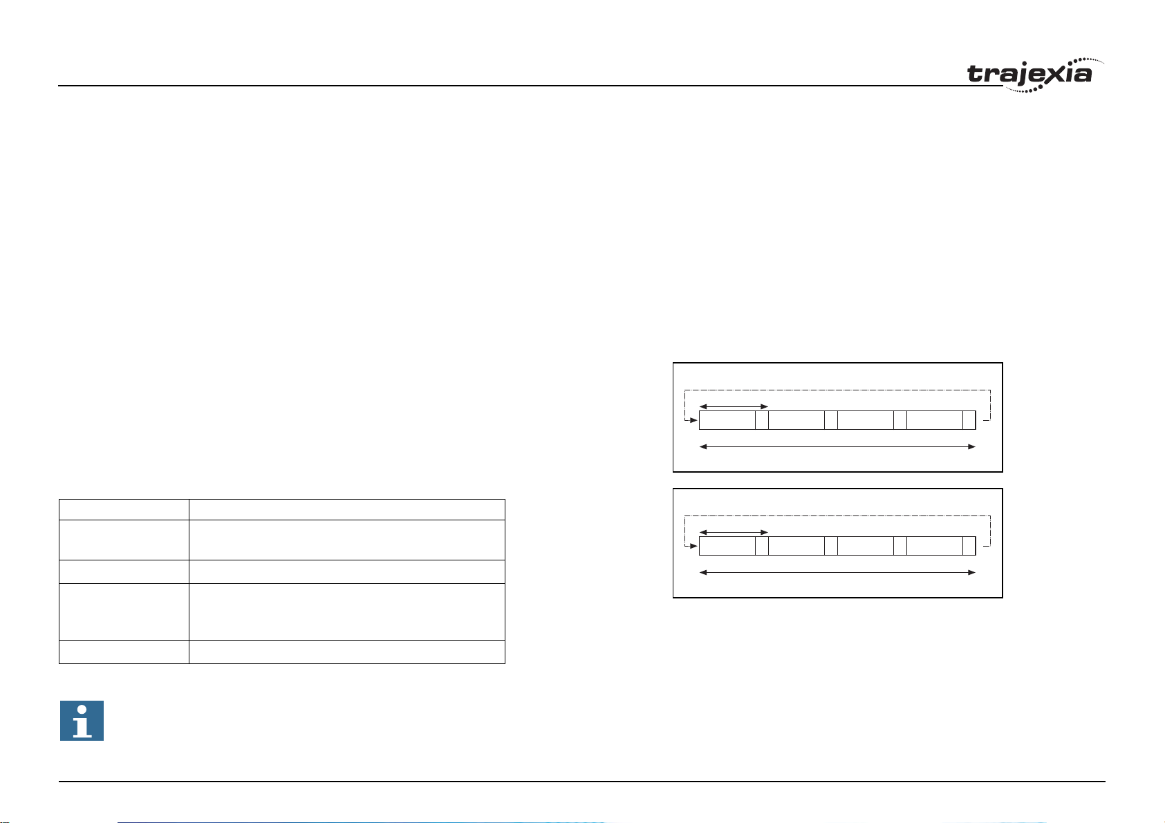
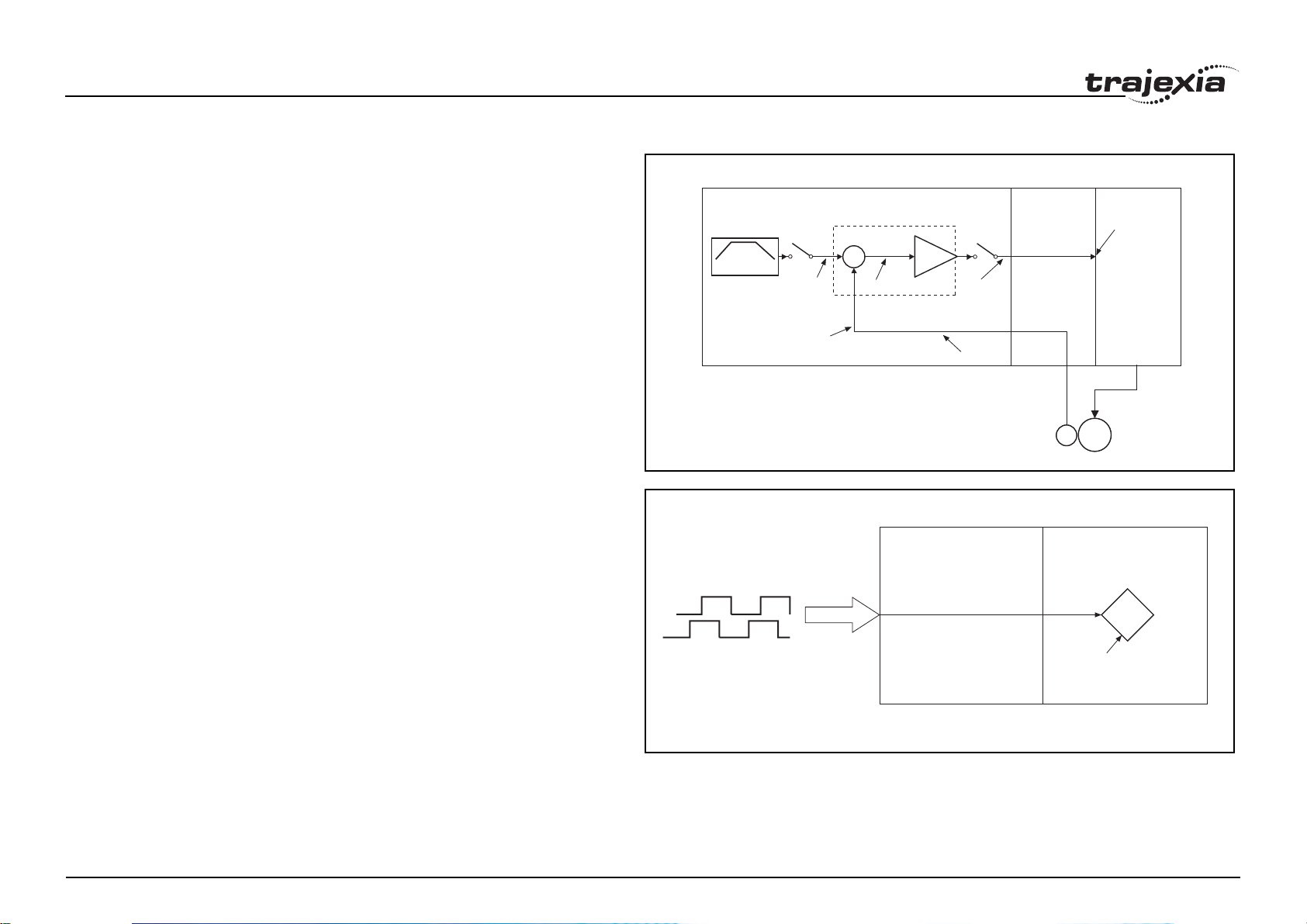
Servo axis ATYPE=44
With SERVO = ON this is an axis with an analogue speed reference output
and incremental encoder feedback input. The position loop is closed in the
TJ1-MC__ which sends the resulting speed reference to the axis.
Profile generator
fig. 35
TJ1-MC__ TJ1-FL02 DRIVE
Demanded
Position
Measured
Position
Position loop
+
_
Following
Error
Speed
Command
Encoder Signal
E
SERVO = OFF SERVO = OFF
+_
10V
M
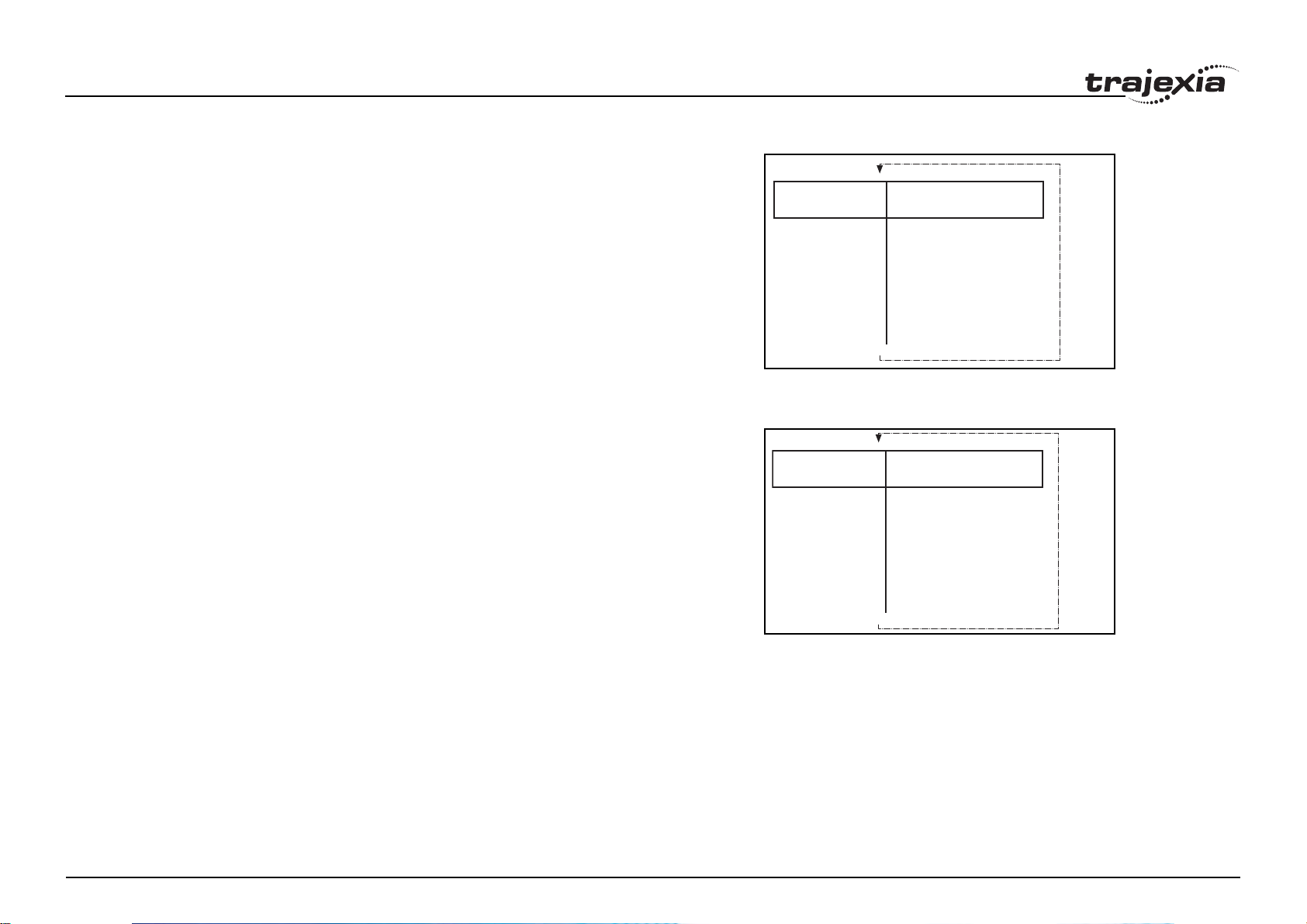
With SERVO = OFF, the position of the external incremental encoder is
fig. 36
read. The analogue output can be set with BASIC commands only and can
Measured
Position
TJ1-MC__ TJ1-FL02
be used for general purposes.
Revision 5.0
HARDWARE REFERENCE MANUAL 36
Page 42

System philosophy
Encoder output ATYPE=45
The position profile is generated and the output from the system is an
incremental encoder pulse. This is useful to control a motor via pulses or as
a position reference for another motion controller.
fig. 37
TJ1-FL02
Profile generator
Absolute Tamagawa encoder ATYPE=46
With SERVO = ON, this is an axis with analogue speed reference output and
absolute Tamagawa encoder feedback. The position loop is closed in the
TJ1-MC__ and the resulting speed reference is sent to the axis.
With SERVO = OFF, the position of the external absolute Tamagawa
encoder is read. The analogue output can be set with BASIC commands
only and can be used for general purposes.
See fig. 35 for reference.
Absolute EnDat encoder ATYPE=47
With SERVO = ON, this is an axis with analogue speed reference output and
absolute EnDat encoder feedback. The position loop is closed in the TJ1MC__ and the resulting speed reference is sent to the axis.
With SERVO = OFF, the position of the external absolute EnDat encoder is
read. The analogue output can be set with BASIC commands only and can
be used for general purposes.
See fig. 35 for reference.
AXIS 1
ATYPE = 45
Demanded
position
Revision 5.0
HARDWARE REFERENCE MANUAL 37
Page 43

System philosophy
Absolute SSI encoder ATYPE=48
With SERVO = ON, this is an axis with analogue speed reference output and
absolute SSI encoder feedback. The position loop is closed in the TJ1-MC__
and the resulting speed reference is sent to the axis.
With SERVO = OFF, the position of the external absolute SSI encoder is
read. The analogue output can be set with BASIC commands only and can
be used for general purposes.
See fig. 35 for reference.
Inverter axis ATYPE=49
This type allows Inverters (with built-in encoder interface) to be controlled on
the MECHATROLINK-II bus as servo axes.
From the controller point of view, Inverter axes are handled the same as
servo axes in MECHATROLINK-II Speed Mode (ATYPE=44).
Unlike the other axis types, this Inverter axis must be defined
programmatically with function 8 of the command INVERTER_COMMAND.
The Speed command to the Inverter and the feedback from the encoder is
refreshed in the Inverter every 5 ms. This is a DPRAM limitation. This means
that the use of the Inverter is similar to the use of a Servo Driver, but the
performance is lower.
Summary of axis types and control modes
The following table lists the axis types and their recommended modes for
speed control, position control and torque control.
/i
Profile generator
SERVO = OFF
Demanded
position
Measured
position
TJ1-MC__
Position loop
+
_
Following
error
Speed
command
fig. 38
SERVO = OFF
TJ1-ML__
ML-II
Speed
command
DPRAM
REFRESH
EVERY 5ms
INVERTER
Speed Loop
M
E
ATYPE SERVO Mode Comment
40 OFF Position
40 ON Position
Revision 5.0
41 OFF Speed
(MECHATROLINK-II)
(MECHATROLINK-II)
(MECHATROLINK-II)
The position loop is closed in the Servo Driver.
No new motion command is allowed.
Recommended mode for position control with
MECHATROLINK-II axes.
Recommended mode for speed control with
MECHATROLINK-II axes. Set the speed with
S_REF.
HARDWARE REFERENCE MANUAL 38
Page 44

System philosophy
ATYPE SERVO Mode Comment
41 ON Position
(MECHATROLINK-II)
42 OFF Torque
(MECHATROLINK-II)
42 ON Position via torque
(MECHATROLINK-II)
44, 46,
47, 48
44, 46,
47, 48
49 OFF Speed Inverter (with built-in encoder interface) control-
49 ON Position Inverter (with built-in encoder interface) control-
OFF Speed
(Flexible Axis)
ON Position
(Flexible Axis)
The position loop is closed in Trajexia. This
gives lower performance than closing the position loop in the Servo Driver.
Recommended mode for torque control with
MECHATROLINK-II axes. Set the torque with
T_REF.
The position loop is closed in Trajexia. The output of the position loop is sent as the torque reference to the Servo Driver.
Recommended mode for speed control with
Flexible Axis.
The position loop is closed in Trajexia. Recommended mode for position control with Flexible
Axis.
led on the MECHATROLINK-II bus as a servo
axis. Set the speed with S_REF.
led on the MECHATROLINK-II bus as a servo
axis. The position loop is closed in Trajexia.
Revision 5.0
HARDWARE REFERENCE MANUAL 39
Page 45
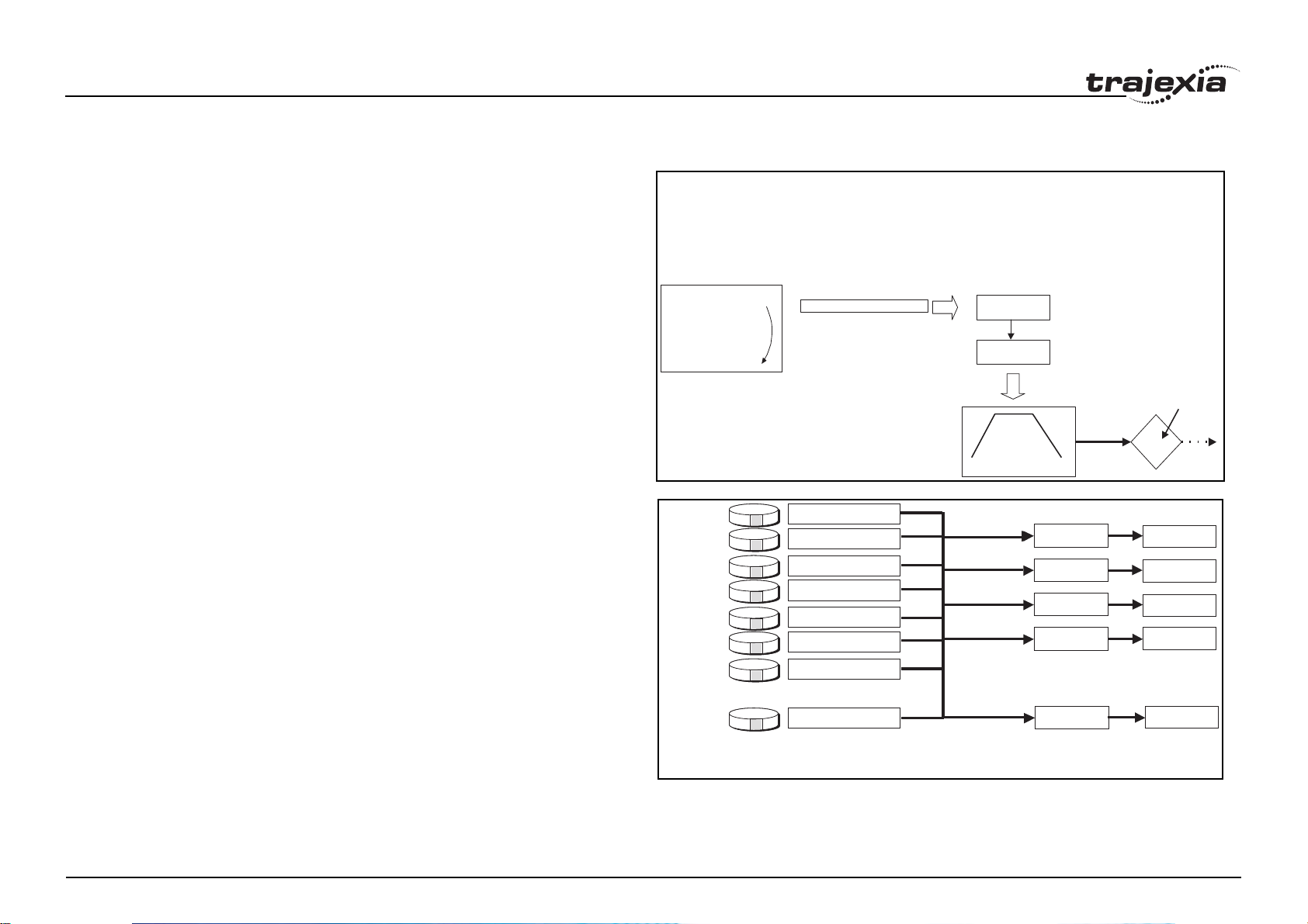
System philosophy
2.8 Motion buffers
The motion buffer is a temporary store of the motion instruction from the
BASIC program to the profile generator.
The BASIC program continues while the instruction waits in the buffer.
There are three types of buffer:
• MTYPE. The current movement that is being executed. MTYPE relates
to the axis and not to the process.
• NTYPE. The new movement that waits for execution. NTYPE relates to
the axis and not to the process.
• Process Buffer. The third buffered movement cannot be monitored. The
process buffer relates to the process and not to the axis.
It is possible to check if the process buffer is full by checking the PMOVE
process parameter.
When a motion instruction is executed in the BASIC program, the instruction
is loaded into the process buffer and distributed to the corresponding axis
buffer in the next motion sequence.
If a fourth motion instruction is executed and the three buffers are full, the
BASIC program stops execution until a process buffer is free for use.
Example of buffered instructions:
BASIC PROGRAM
BASIC PROGRAM
..... ..
..... ..
MOVE(-500)
MOVE(-500)
..... ..
..... ..
MOVE(1000)
MOVE(1000)
..... ..
..... ..
CONNECT(1,1)
CONNECT(1,1)
..... ..
Process 1
Process 2
Process 3
Process 4
Process 5
Process 6
Process 7
CONNECT(1,1) AXIS(2)
PROCESS BUFFER
Process Buffer
Process Buffer
Process Buffer
Process Buffer
Process Buffer
Process Buffer
Process Buffer
fig. 39
Profile generator
fig. 40
Axis 0
Axis 1
Axis 2
Axis 3
AXIS BUFFER
(one per axis)
NTYPE
MTYPE
Waiting to be executed
MOTION COMMAND
Currently executed
MOTION COMMAND
DEMAND
POSITION
WAITING EXECU TING
NTYPE
NTYPE
NTYPE
NTYPE MTYPE
MTYPE
MTYPE
MTYPE
Process 14
Each process has its own
“Process Buffer”
Revision 5.0
Program Buffer
Each Axis has its own
2 buffers: NTYPE & MTYPE
NTYPE MTYPE
HARDWARE REFERENCE MANUAL 40
Axis 15
Page 46

System philosophy
e
u
EXAMPLE:
BASIC PROGRAM
.......
MOVE(-500)
.......
MOVE(1000)
.......
DAT UM(3)
.......
MOVE(200)
.......
BASIC PROGRAM
.......
MOV E(- 50 0)
.......
MOVE(1000)
.......
DATUM( 3)
.......
MOVE(200)
.......
BASIC PROGRAM
.......
MOV E(-50 0)
.......
MOVE(1000)
.......
DAT UM(3)
.......
MOVE(200)
.......
BASIC PROGRAM
BASIC PROGRAM
.......
.......
MOV E(-50 0)
MOV E(-50 0)
.......
.......
MOVE(1000)
MOVE(1000)
.......
.......
DAT UM(3)
DAT UM(3)
.......
.......
MOVE(200)
MOVE(200)
.......
.......
BASIC PROGRAM
BASIC PROGRAM
.......
.......
MOVE(-500)
MOVE(-500)
.......
.......
MOVE(1000)
MOVE(1000)
.......
.......
DAT UM(3)
DAT UM(3)
.......
.......
MOVE(200)
MOVE(200)
.......
.......
BASIC PROGRAM
BASIC PROGRAM
.......
.......
MO VE(-50 0)
MO VE(-50 0)
.......
.......
MOVE(1000)
MOVE(1000)
.......
.......
DAT UM(3)
DAT UM(3)
.......
.......
MOVE(200)
MOVE(200)
.......
.......
BUFFER
--------------------------------NTYPE IDLE
--------------------------------MTYPE MOVE(-500)
- - - -
BUFFER
- - - -
--------------------------------NTYPE MOVE(1000)
--------------------------------MTY PE MOV E( -5 00)
BUFFER
DATUM(3)
-------------------------- ------NTYPE MOVE(1000)
-------------------------- ------MTYPE MOVE(-500)
BUFFER
BUFFER
MOVE(200)
MOVE(200)
-------------------------- -------
-------------------------- ------NTYPE DATUM(3)
NTYPE DATUM(3)
-------------------------- -------
-------------------------- ------MTYPE MOVE(1000)
MTYPE MOVE(1000)
BUFFER
BUFFER
- - - - - -
- - - - - -
---------------------------------
--------------------------------NTYPE MOVE(200)
NTYPE MOVE(200)
---------------------------------
--------------------------------MTYPE DATUM(3)
MTYPE DATUM(3)
BUFFER
BUFFER
- - - - - -
- - - - - -
---------------------------------
--------------------------------NTYPE IDLE
NTYPE IDLE
---------------------------------
--------------------------------MTYPE MOVE(200)
MTYPE MOVE(200)
MOVE -500
MOV E -50 0
MOVE -500
MOVE -500
MOVE -500
MOVE -500
MOVE -500
MOVE -500
MOVE -500
fig. 41
MOVE 1000
MOVE 1000
MOVE 1000
MOVE 1000
MOVE 1000
MOVE 1000
DAT UM (3)
DAT UM (3)
DAT UM (3)
DAT UM (3)
MOVE 200
MOVE 200
1.- All buffers are empty
and a movement is
loaded. The movement
starts to execute.
2.- A second movement is
loaded while the first one
is not finished.
The new movement waits in th
second buffer.
3.- A third movement can
still be stored in the process b
If the basic
program reaches
‘MOVE(200)’ it will wait.
4.- The first movement has
finished. Thebuffer moves
by one position .
The next movement starts to
execute.
5.- As the sent
movements are finished,
the buffer
empties.
6.- If no new movements
are executed, finally, the
buffer will become empty
and the profile generator
becomes inactive.
Revision 5.0
HARDWARE REFERENCE MANUAL 41
Page 47

System philosophy
2.9 Mechanical system
2.9.1 Inertia ratio
The inertia ratio is a stability criterion. The higher the intertia of the load in
relation to the intertia of the motor, the lower the gains you can set in your
system before you reach oscillation, and the lower the performance you can
reach.
With a ratio of 1:30 for small Servo Drivers and a ratio of 1:5 for big Servo
Drivers you can reach the maximum dynamic of the motor-driver
combination.
2.9.2 Rigidity
If a machine is more rigid and less elastic, you can set higher gains without
vibration, and you can reach higher dynamic and lower Following Error.
2.9.3 Resonant frequency
A mechanical system has at least one resonant frequency. If you excite your
mechanical system to the resonant frequency, it starts oscillating. For motion
systems, it is best to have mechanical systems with a very high resonant
frequency, that is, with low inertia and high rigidity.
The resonant frequency of the mechanical system is the limit for the gain
settings.
Revision 5.0
HARDWARE REFERENCE MANUAL 42
Page 48

Hardware reference
3 Hardware reference
3.1 Introduction
Trajexia is OMRON's motion platform that offers you the performance and
the ease of use of a dedicated motion system.
Trajexia is a stand-alone modular system that allows maximum flexibility and
scalability. At the heart of Trajexia lies the TJ1 multi-tasking motion
coordinator. Powered by a 32-bit DSP, it can do motion tasks such as e-cam,
e-gearbox, registration control and interpolation, all via simple motion
commands.
Trajexia offers control of up to 16 axes over a MECHATROLINK-II motion
bus or traditional analogue or pulse control with independent position, speed
or torque control for every axis. And its powerful motion instruction set
makes programming intuitive and easy.
You can select from a wide choice of best-in-class rotary, linear and directdriver servos as well as Inverters. The system is scalable up to 16 axes and
8 Inverters & I/O modules.
3.1.1 Trajexia High-Lights
The main high-lights of the trajexia system are as follows:
Direct connectivity via Ethernet
Trajexia's Ethernet built-in connector provides direct and fast connectivity to
PCs, PLCs, HMIs and other devices while providing full access to the drivers
over a MECHATROLINK-II motion bus. It allows explicit messaging over
Ethernet and through MECHATROLINK-II to provide full transparency down
to the actuator level, and making remote access possible.
NS-series HMI
Digital I/O
Hostlink
CJ-series PLC CX-one
Ethernet
MECHATROLINK-II
fig. 1
Trajexia Tools
PROFIBUS-DP
Master
DEVICENET
Master
CANopen
Master
Keep your know-how safe
Revision 5.0
Trajexia's encryption method guarantees complete protection and
confidentiality for your valuable know-how.
HARDWARE REFERENCE MANUAL 43
Page 49

Hardware reference
Serial Port and Local I/Os
A serial connector provides direct connectivity with any OMRON PLC, HMIs
or any other field device. 16 Inputs and 8 outputs are freely configurable
embedded I/Os in the controller to enable you to tailor Trajexia to your
machine design.
MECHATROLINK-II Master
The MECHATROLINK-II master performs control of up to 16 servos,
Inverters or I/Os while allowing complete transparency across the whole
system.MECHATROLINK-II offers the communication speed and time
accuracy essential to guarantee perfect motion control of servos. The
motion cycle time is selectable between 0.5 ms, 1 ms or 2 ms.
TJ1-FL02 (Flexible Axis Unit)
The TJ1-FL02 allows full control of two actuators via an analogue output or
pulse train. The module supports the main absolute encoder protocols
allowing the connection of an external encoder to the system.
Drives and Inverters
A wide choice of rotary, linear and direct-driver servos as well as Inverters
are available to fit your needs in compactness, performance and reliability.
The Inverters connected to the MECHATROLINK-II are driven at the same
update cycle time as the Servo Drivers.
Remote I/Os
The I/Os on the MECHATROLINK-II motion bus provide for system
expansion while keeping the devices under one motion bus.
PROFIBUS-DP
The PROFIBUS-DP slave allows connectivity to the PROFIBUS network in
your machine.
DeviceNet
Revision 5.0
The DeviceNet slave allows connectivity to the DeviceNet network in your
machine.
HARDWARE REFERENCE MANUAL 44
Page 50

Hardware reference
CANopen
The CANopen master allows connectivity to the CANopen network in your
machine.
3.1.2 Trajexia Studio
One software
Trajexia's intuitive and easy programming tool, based on the Motion BASIC
instruction set, includes dedicated commands for linking axes, e-cams, egearboxes etc. Multi-tasking provides flexibility in application design. The
motion commands are "buffered" so the BASIC programs are executed
while motion movements are executed.
One connection
The parameters and functions inside the drivers on the MECHATROLINK-II
are fully accessible from the Ethernet connection.
One minute
Trajexia Studio includes advanced debugging tools, including trace and
oscilloscope functions, to ensure efficient operation and minimum downtime.
The servos, Inverters and I/Os connected to the MECHATROLINK-II motion
bus are automatically identified and configured, allowing you to set up your
system in minutes.
3.1.3 This manual
This Hardware Reference Manual gives the dedicated information for:
• The description, connections and use of the Trajexia units
• The description, connections and use of the MECHATROLINK-II slaves
• A detailed philosophy of the system design to obtain the best results for
Trajexia
fig. 2
Revision 5.0
HARDWARE REFERENCE MANUAL 45
Page 51

Hardware reference
3.2 All units
3.2.1 System installation
A Trajexia system consists of these units:
• A Power Supply Unit.
• A TJ1-MC__ (Motion Controller Unit). This can be one of these:
- TJ1-MC16. It supports 16 real or virtual axes, and 16 axes in total.
- TJ1-MC04. It supports 5 real and up to 16 virtual axes, 16 axes in
total.
• Up to 7 expansion units.
• A TJ1-TER (Terminator Unit).
The expansion units (unit numbers 0-6) can be arranged in any order. The
TJ1-MC__ autodetects all units.
A Trajexia system with a TJ1-MC16 can include:
• 0 to 4 TJ1-ML__ units (MECHATROLINK-II Master Unit).
• 0 to 7 TJ1-FL02 units.
• 0 or 1 TJ1-PRT (PROFIBUS-DP Slave Unit) or TJ1-DRT units
(DeviceNet Slave Unit)
1
.
• 0 or 1 TJ1-CORT units (CANopen Master Unit).
A Trajexia system with a TJ1-MC04 can include:
• 0 to 4 TJ1-ML__ units.
• 0 to 3 TJ1-FL02 units.
• 0 or 1 TJ1-PRT or TJ1-DRT units
1
.
• 0 or 1 TJ1-CORT units.
fig. 3
-1Unit number: 012345 6
Revision 5.0
1. Trajexia does not support both a TJ1-PRT and a TJ1-DRT unit in the same
system.
HARDWARE REFERENCE MANUAL 46
Page 52

Hardware reference
The figure is an example of a simple configuration.
A. Power supply
B. TJ1-MC__.
C. TJ1-ML__.
D. Sigma-II Servo Driver
E. NS115 MECHATROLINK-II Interface Unit.
F. Sigma-II servo motor
G. TJ1-TER.
M
C
1
OMRON
MOTION CONTROLLER
fig. 4
G
C
B
A
6
0
1
2
3
4
ML16
5
6
7
CN3
CN1
TERM
ON/OFF
WIRE
2/4
CN2
RUN
8F
CN1
F
D
E
Revision 5.0
HARDWARE REFERENCE MANUAL 47
Page 53

Hardware reference
1. Remove all the units from the packaging. Make sure all units are
complete.
2. Do not remove the protection labels from the units.
3. To disconnect the TJ1-MC__ and the TJ1-TER, push the clips (A) on top
and bottom of the TJ1-TER to the front.
4. Disconnect the TJ1-TER from the TJ1-MC__.
5. Push the clips (A) on top and bottom of all the units to the front.
fig. 5
A
MC16
0
O
1
M
R
O
N
2
M
OTION CON
3
TROLLER
4
5
6
7
C
N3
CN1
TER
M
O
N/O
FF
W
IRE
2/4
C
N2
fig. 6
A
MC16
0
OMRON
1
2
MOTION CONTROLLER
3
4
5
6
7
CN3
CN1
TERM
ON/OFF
W
IRE
2/4
CN2
Revision 5.0
HARDWARE REFERENCE MANUAL 48
Page 54

Hardware reference
6. Attach the TJ1-MC__ (C) to the Power Supply Unit (B).
7. Push the clips (A) on top and bottom to the rear.
fig. 7
MC16
OMRON
MOTION CONTROLLER
fig. 8
CB
0
1
2
3
4
5
6
7
CN3
CN1
TERM
ON/OFF
W
IRE
2/4
CN2
A
M
C16
0
OM
1
RON
2
MOTION CONTROLLER
3
4
5
6
7
CN3
CN1
TERM
ON/OFF
WIRE
2/4
CN2
Revision 5.0
HARDWARE REFERENCE MANUAL 49
Page 55

Hardware reference
8. Repeat the previous two steps for all other units.
9. Make sure the last unit is the TJ1-TER.
10. Pull down all the clips (D) on all units.
11. Attach the Trajexia system to the DIN rail in an upright position to
provide proper cooling. The recommended DIN rail is of type PFP100N2, PFP-100N or PFP-50N.
12. Push all the clips (D) up on all units.
13. After you complete the wiring of the units, remove the protection labels
from the units.
fig. 9
A
MC16
0
OMRON
1
2
M
OTIO
N C
3
ONTR
O
4
LLER
5
6
7
CN3
ML16
RUN
C
N
1
TERM
O
N/O
FF
W
IRE
2/4
CN2
8F
CN1
fig. 10
D
MC16
0
OM
1
R
O
N
2
MOTION CONTROLLER
3
4
ML16
5
6
7
CN3
CN1
TERM
ON/OFF
WIRE
2/4
CN2
R
U
N
8F
CN1
Revision 5.0
HARDWARE REFERENCE MANUAL 50
Page 56

Hardware reference
14. Do not install the Trajexia units in one of these positions:
• Upside down.
• With the top side forward.
• With the bottom forward.
•Vertically.
fig. 11
N1
C
8F
N
RU
2
N
C
2/4
E
IR
W
F
F
/O
N
O
M
ER
T
3
N
C
1
N
C
7
R
LLE
O
TR
ON
N C
OTIO
M
6
OMRON
5
4
3
2
1
0
ML16
MC16
CN1
N
8F
U
R
16
L
M
0
C16
M
2
CN
1
E
OFF
CN
2/4
N/
WIR
O
TERM
7
6
5
4
3
2
1
R
CN3
MOTION CONTROLLE
OMRON
Revision 5.0
HARDWARE REFERENCE MANUAL 51
Page 57

Hardware reference
15. When you design a cabinet for the units, make sure that the cabinet
allows at least 20 mm of space around the units to provide sufficient
airflow. We advise to allow at least 100 mm of space around the units.
3.2.2 Environmental and storage for all units
/i
Item Specification
Ambient operating temperature 0 to 55°C
Ambient operating humidity 10 to 90% RH. (with no condensation)
Ambient storage temperature -20 to 70°C (excluding battery)
fig. 12
Ambient storage humidity 90% max. (with no condensation)
Atmosphere No corrosive gases
Vibration resistance 10 to 57 Hz: (0.075 mm amplitude): 57 to 100 Hz:
Acceleration: 9,8 m/s2, in X, Y and Z directions for
80 minutes
Shock resistance 147 m/s
Insulation resistance 20 MΩ
Dielectric strength 500 VAC
Protective structure IP20
Revision 5.0
International standards CE, EN 61131-2, cULus, Lloyds
RoHS compliant
2
, 3 times each X, Y and Z directions
HARDWARE REFERENCE MANUAL 52
Page 58

Hardware reference
3.2.3 Unit dimensions
The dimensions for the units of the Trajexia system are as follows:
Trajexia motion controller
All measurements are in mm.
fig. 13
65
62
71
94
90
70.3
Revision 5.0
HARDWARE REFERENCE MANUAL 53
Page 59

Hardware reference
Trajexia units
All measurements are in mm.
fig. 14
31
39.9
94
90
70.3
Revision 5.0
HARDWARE REFERENCE MANUAL 54
Page 60

Hardware reference
Trajexia system
All measurements are in mm.
P
A202
65
fig. 15
90
94
The installation depth of the Trajexia system is up to 90 mm, depending on
the modules that are mounted. Allow sufficient depth in the control cabinet.
3.2.4 Wire the I/O connectors
To wire the I/O connectors of the TJ1-MC__ and the TJ1-FL02 units, do
Revision 5.0
these steps:
62
fig. 16
94
3145
70.30
81.60 to 89.0 mm
29.7
90
HARDWARE REFERENCE MANUAL 55
Page 61

Hardware reference
1. Strip the wires.
2. To make it easier to insert the wires, twist them.
3. If necessary, crimp the plain (top) ferrules or the collared (bottom)
ferrules.
4. Insert the screwdriver into the inner (square) hole. Push firmly.
5. Insert the wire into the outer (circular) hole.
6. Remove the screwdriver.
7. Make sure that there are no loose strands.
Wiring specifications
/i
Item Specification
Wire types 0.14−1.0 mm
Solid, stranded or stranded with ferrule:
• Crimp ferrules according to DIN46228/1
• Crimp ferrules wit plastic collar according to DIN46228/4
• With recommended tool Weidmüller PZ6
Insertion tool 2.5 mm flat-bladed screwdriver
Recommended
ferrule types
Stripping length 7 mm without ferrules (tolerance: +1 mm, −0 mm)
Weidmüller
AEH H0,14/12
AEH H0,25/12
AEH H0,34/12
10 mm with ferrules (tolerance: +1 mm, −0 mm)
2
fig. 17
Conductor size
/i
Item Specification
Clamping range 0.08−1.0 mm
Wires without ferrule 0.5−1.0 mm
Wires with ferrule AEH H0,14/12, 0.13 mm
Revision 5.0
AEH H0,25/12, 0.25 mm
AEH H0,34/12, 0.34 mm
HARDWARE REFERENCE MANUAL 56
2
2
2
2
2
Page 62

Hardware reference
3.3 Power Supply Unit (PSU)
3.3.1 Introduction
The PSU supplies power to the other units in the Trajexia system. You can
use three different types of Power Supply Unit with the Trajexia system:
• CJ1W-PA202
• CJ1W-PA205R
• CJ1W-PD025.
3.3.2 PSU Connections
Each Power Supply Unit has six terminals:
/i
Item CJ1W-PA202 CJ1W-PA205R CJ1W-PD025
A 110 - 240 VAC input 110 - 240 VAC input 24 VDC input
B 110 - 240 VAC input 110 - 240 VAC input 0 V input
C Line earth Line earth Line earth
D Earth Earth Earth
EN/C
F N/C Wdog relay contact N/C
1
Wdog relay contact
N/C
1. Terminals E and F for the CJ1W-PA205R are relay contacts that close
when Wdog is enabled. Refer to the BASIC Commands in the Programming manual.
Caution
Always connect to a class-3 ground (to 100Ω or less) when installing the Units.
Not connecting to a class-3 ground may result in electric shock.
Revision 5.0
G
XXXXX
AC100
-240V
INPUT
L2/N
NC
NC
L1
fig. 18
POWER
A
B
C
D
E
F
HARDWARE REFERENCE MANUAL 57
Page 63

Hardware reference
Caution
A ground of 100Ω or less must be installed when shorting the GR
and LG terminals on the Power Supply Unit.
Not connecting a ground of 100Ω or less may result in electric
shock.
Each Power Supply Unit has one green LED (G). This LED comes on when
you connect the Power Supply Unit to the power source.
Caution
Tighten the screws of the power supply terminal block to the
torque of 1.2 N·m. Loose screws can result in short-circuit, malfunction or fire.
3.3.3 PSU Specifications
/i
Power
Supply
Unit
CJ1W-PA202 110 - 240 VAC 2.8 A 0.4 A 14 W
CJ1W-PA205R 110 - 240 VAC 5.0 A 0.8 A 25 W
CJ1W-PD025 24 VDC 5.0 A 0.8 A 25 W
Input
voltage
Maximum current consumption Output
5 V group 24 V group
power
Caution
The amount of current and power that can be supplied to the system is limited by the capacity of the Power Supply Unit. Refer to
this table when designing your system so that the total current
consumption of the units in the system does not exceed the maximum current for each voltage group.
Revision 5.0
The total power consumption must not exceed the maximum for
the Power Supply Unit.
HARDWARE REFERENCE MANUAL 58
Page 64

Hardware reference
3.3.4 PSU box contents
• Safety sheet.
• Power Supply Unit.
• Protection label attached to the top surface of the unit.
3.4 TJ1-MC__
3.4.1 Introduction
The TJ1-MC__ is the heart of the Trajexia system. You can program the
TJ1-MC__ with the BASIC programming language to control the expansion
units and the servo motors attached to the expansion units. Refer to the
Programming Manual.
There are two versions of the TJ1-MC__:
The TJ1-MC04 supports 5 axes (up to 4 axis on MECHATROLINK-II)
The TJ1-MC16 supports 16 axes.
The TJ1-MC__ has these visible parts:
/i
fig. 19
Part Description
ALED display
B I/O LEDs 0 - 7
C Battery
D Ethernet connector
E TERM ON/OFF switch
F WIRE 2/4 switch
G Serial connector
H 28-pin I/O connector
A
B
C
D
E
F
G
H
Revision 5.0
HARDWARE REFERENCE MANUAL 59
Page 65

Hardware reference
3.4.2 LED Display
The LED display shows the following information:
Information When
IP address and subnet mask
IP address Shows 4 times when you connect an Ethernet cable to the Ethernet
RUN When the TJ1-MC__ operates a Servo Driver.
OFF When the TJ1-MC__ does not operate a Servo Driver.
ERR + code When an error occurs in the Trajexia system.
Shows 3 times when you connect the Trajexia system to the power
supply.
connector of the TJ1-MC__ and to a PC.
The code is the error code. Refer to troubleshooting chapter in the
Programming Manual.
fig. 20/i
Revision 5.0
HARDWARE REFERENCE MANUAL 60
Page 66

Hardware reference
3.4.3 TJ1-MC__ Connections
The TJ1-MC__ comes with these connectors:
• One Ethernet connector, to connect to a PC or Ethernet network (D)
• One serial connector (G).
• One 28-pin I/O connector (H).
The parts for the serial connector and the 28-pin connector are supplied.
Ethernet connector
The Ethernet connector is used to connect the TJ1-MC__ to a PC or
Ethernet network. The Ethernet connector is the only connection that can be
used to program the system. Use either a crossover or a Ethernet patch
cable for this connection. If you connect the PC directly to the TJ1-MC__,
and not via a hub or any other network device, the PC must have a fixed IP
address.
The TJ1-MC__ automatically detects when a cable is connected to the
Ethernet connector.
BASIC installation precautions
Make sure that the Ethernet system is to the IEEE Std 802.3 standard.
Do not install the Ethernet system near a source of noise.
Environmental precautions
UTP cables are not shielded. In environments that are subject to noise use a
system with shielded twisted-pair (STP) cable and hubs suitable for an FA
environment.
Install twisted-pair cables away from high-voltage lines and devices that
generate noise.
Install twisted-pair cables in locations that are free of high humidity and
excessive dust and contaminates.
fig. 21
A
B
C
D
E
F
G
H
Revision 5.0
HARDWARE REFERENCE MANUAL 61
Page 67

Hardware reference
Serial connector
The serial connector allows for three communication standards:
• RS232.
• RS422.
• RS485.
/i
Pin Communication Connection
1 RS422/RS485 /Tx
2 RS232 Tx
3 RS232 Rx
4N/C N/C
5N/C N/C
6 RS422/RS485 /Rx
7 RS422/RS485 Tx
8 RS422/RS485 Rx
9 RS232 0 V
TERM ON/OFF Switch
Sets the termination on/off of the RS422 / 485 serial connection. The setting
of the TERM ON/OFF switch depends on the communication standard of the
serial connection and the position of the TJ1-MC__ in the network:
/i
fig. 22
5
9
8
7
6
4
3
2
1
Communication
standard
RS422 or RS485 First or last Left (on)
RS422 or RS485 Not the first and not the last Right (off)
Revision 5.0
HARDWARE REFERENCE MANUAL 62
Position of the TJ1-MC__ Setting of the TERM ON/OFF
switch
Page 68

Hardware reference
WIRE 2/4 Switch
The WIRE 2/4 switch sets the communication standard for the RS422/485
serial connection. To use one of the communication standards, do this:
/i
Communication standard How to select it
RS422 Set the WIRE 2/4 switch right
RS485 Set the WIRE 2/4 switch left
fig. 23
A
B
C
Note
In RS485 mode, the transmit pair is connected to the receive pair.
D
E
F
G
H
Revision 5.0
HARDWARE REFERENCE MANUAL 63
Page 69

Hardware reference
28-Pin I/O connector
The 28 pin connector is a Weidmuller connector designation:
B2L 3.5/28 LH.
Pin Connection Pin Connection
1 0 V input common 2 0 V input common
3 Input 0 4 Input 1
5 Input 2 6 Input 3
7 Input 4 8 Input 5
9 Input 6 10 Input 7
11 Input 8 12 Input 9
13 Input 10 14 Input 11
11
fig. 24/i
1
3
5
7
9
2
4
6
8
10
12
15 Input 12 16 Input 13
17 Input 14 18 Input 15
19 Output 8 20 Output 9
21 Output 10 22 Output 11
23 Output 12 24 Output 13
25 Output 14 26 Output 15
27 0 V output common 28 24V Power supply Input for
the Outputs.
LEDs 0 - 7
The I/O LEDs reflect the activity of the input and outputs. You can use the
BASIC DISPLAY=n command to set the LEDs.
The table below lists the configuration for LEDs 0 - 7 and the DISPLAY=n
command where n ranges from 0 to 7.
/i
LED
Revision 5.0
label
0 IN 0 IN 8 IN 16 IN 24 OUT 0 OUT 8 OUT 16 OUT 24
1 IN 1 IN 9 IN 17 IN 25 OUT 1 OUT 9 OUT 17 OUT 25
n=0 n=1 n=2 n=3 n=4 n=5 n=6 n=7
13
15
17
19
21
23
25
27
14
16
18
20
22
24
26
28
HARDWARE REFERENCE MANUAL 64
Page 70

Hardware reference
LED
label
2 IN 2 IN 10 IN 18 IN 26 OUT 2 OUT 10 OUT 18 OUT 26
3 IN 3 IN 11 IN 19 IN 27 OUT 3 OUT 11 OUT 19 OUT 27
4 IN 4 IN 12 IN 20 IN 28 OUT 4 OUT 12 OUT 20 OUT 28
5 IN 5 IN 13 IN 21 IN 29 OUT 5 OUT 13 OUT 21 OUT 29
6 IN 6 IN 14 IN 22 IN 30 OUT 6 OUT 14 OUT 22 OUT 30
7 IN 7 IN 15 IN 23 IN 31 OUT 7 OUT 15 OUT 23 OUT 31
n=0 n=1 n=2 n=3 n=4 n=5 n=6 n=7
For example, if you use the DISPLAY=1 command, LED 5 reflects the
activity of the input in 13 (pin16) of the 28-pin I/O connector.
Digital inputs
The following table and illustration details the digital input (Input 0 to Input
15) specifications for the I/O:
/i
Item Specification
Type PNP/NPN
Maximum voltage 24 VDC + 10%
Input current 5 mA at 24 VDC
ON voltage 14.4 VDC
OFF voltage 5.0 VDC max.
External power
supply 24V
Input
0V Input
fig. 25
TJ 1-MC 16
3
1
The timings are dependant upon the MC16’s servo period, and include
0V common for Input circuits
physical delays in the input circuit.
Maximum response times of 1250 µs (for servo periods of 0.5 ms or 1.0 ms)
or 2500 µs (for a servo period of 2.0 ms) are achieved between a change in
the input voltage and a corresponding change in the IN Parameter.
Revision 5.0
HARDWARE REFERENCE MANUAL 65
Page 71

Hardware reference
Digital outputs
The following table and illustration details the digital output (O8 to O15)
specifications:
/i
Item Specification
Type PNP
Maximum voltage 24 VDC + 10%
Current capacity 100 mA each output (800 mA for a group of 8)
Max. Voltage 24 VDC + 10%
Protection Over current, Over temperature and 2A fuse on
Common
The timings are dependant upon the MC16’s servo period, and include
physical delays in the output circuit.
Maximum response times of 250 µs on and 350 µs off (for servo periods of
0.5 ms or 1.0 ms) or 500 µs on and 600 µs off (for a servo period of 2.0 ms)
are achieved between a change in the OP parameter and a corresponding
change in the digital output circuit.
lvanically
Equivalent
circuit
isolated from the system)
Internal circuits (ga
To other output circuits
fig. 26
TJ 1-MC 16
2A Fuse
27
24V output supply28
19 O8
0Vout
External
power
supply
24V
Load
Revision 5.0
HARDWARE REFERENCE MANUAL 66
Page 72

Hardware reference
3.4.4 Battery
The backup battery provides power to the RAM, where programs and global
variables are stored, and real Time Clock when the power supply is off. You
must replace it every five years. The part number of the backup battery is
CJ1W-BAT01.
To replace the battery the power must not be off for more than five minutes
to ensure no backup memory loss. If the TJ1-MC__ has not been on, set the
unit to on for at least five minutes before you replace the battery else the
capacitor that gives backup power to the memory is not fully changed and
backup memory may be lost before the new battery is inserted.
3.4.5 TJ1-MC__ Specification
/i
Item Specification
TJ1-MC04 TJ1-MC16
Power supply 5 VDC and 24 VDC (supplied by a Power Supply Unit)
fig. 27
A
B
C
D
E
F
G
H
Total power consumption 3.3 W
Current consumption 650 mA at 5 VDC
Approximate weight 230 g
Number of axes 5 (up to 4 axis on MECHA-
TROLINK-II)
Number of Inverters and I/Os Up to 8 on MECHATROLINK-II, depending on the type of
Revision 5.0
Number of TJ1-ML__ units Up to 4
Real Time Clock Yes
HARDWARE REFERENCE MANUAL 67
TJ1-ML__ in the system.
16
Page 73

Hardware reference
Item Specification
TJ1-MC04 TJ1-MC16
Servo period 0.5 ms, 1 ms or 2 ms
Programming language BASIC-like motion language
Multi-tasking Up to 14 tasks
Digital I/O 16 digital inputs and 8 digital outputs, freely configurable
Measurement units User-definable
Available memory for user programs
Data storage capacity Up to 2 MB flash data storage
Saving program data on the
TJ1-MC__
Saving program data on the PC Trajexia Tools software manages backups on the hard-
Communication connectors • 1 Ethernet connection
Firmware update Via Trajexia Tools software
Electrical characteristics of the
Ethernet connector
Ethernet connector RJ45
500 kB
• RAM and flash memory backup
• Battery backup
disk of the PC
• 2 serial connections
Conforms to IEEE 802.3 (100BaseT)
Serial connectors 1 and 2
/i
Item Specification
Electrical characteristics • PORT1: RS232C, non-isolated
• PORT2: RS485/RS422A, isolated
Connector SUB-D9 connector
Baud rate 1200, 2400, 4800, 9600, 19200 and 38400 bps
Revision 5.0
Transmission format, databit length 7 or 8 bit
Transmission format, stop bit 1 or 2 bit
HARDWARE REFERENCE MANUAL 68
Page 74

Hardware reference
Item Specification
Transmission format, parity bit Even/odd/none
Transmission mode • RS232C: Point-to-point (1:1)
• RS422/485: Point-to-multipoint (1:N)
Transmission protocol • Host link master protocol
• Host link slave protocol
• ASCII general purpose
Galvanic isolation RS422/485 connector only
Communication buffers 254 bytes
Flow control None
Terminator Yes, selected by switch
Maximum cable length • RS232C: 15 m
• RS422/485: 100 m
3.4.6 TJ1-TER
The TJ1-TER makes sure that the internal data bus of the Trajexia system
fig. 28
functions correctly. A Trajexia system must always contain a TJ1-TER as the
last unit.
Revision 5.0
HARDWARE REFERENCE MANUAL 69
Page 75

Hardware reference
3.4.7 TJ1-MC__ box contents
• Safety sheet.
• TJ1-MC__ (battery included).
• Protection label attached to the top surface of the TJ1-MC__.
• TJ1-TER, attached to the TJ1-MC__.
• Parts for a serial connector.
• Parts for an I/O connector.
• Two metal DIN-rail clips, to prevent the Trajexia system from sliding off
the rail.
• White clip, to replace the yellow clip of the Power Supply Unit.
3.5 TJ1-ML__
3.5.1 Introduction
The TJ1-ML__ controls MECHATROLINK-II devices in a cyclic and
deterministic way. MECHATROLINK-II devices can be:
• Servo Drivers.
• Inverters.
•I/Os.
The TJ1-ML__ has these visible parts:
/i
Part Description
ALED indicators
ML16
fig. 29
RUN
BF
CN1
A
B
B CN1 MECHATROLINK-II bus connector
Together the TJ1-ML__ and its devices form a serial network. The first unit in
the network is the TJ1-ML__.
• One TJ1-ML16 can control 16 devices.
• One TJ1-ML04 can control 4 devices.
Revision 5.0
HARDWARE REFERENCE MANUAL 70
Page 76
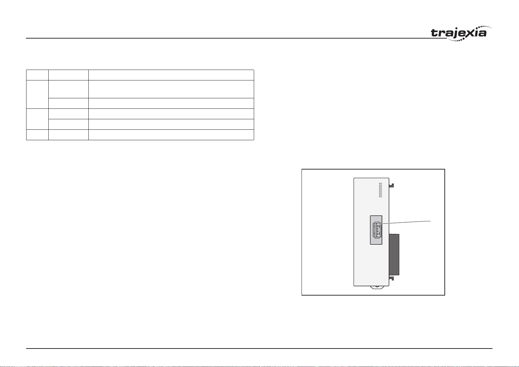
Hardware reference
3.5.2 LEDs description
/i
Label Status Description
run off Start-up test failed. Unit not operational
Operation stopped. Fatal error
on Start-up test successful. Normal operation
BF off Normal operation
on A fault in the MECHATROLINK-II bus
- Reserved
3.5.3 TJ1-ML__ connection
The MECHATROLINK-II bus connector (A) fits a MECHATROLINK-II
connector. Use this connector to connect the TJ1-ML__ to a
MECHATROLINK-II network.
The MECHATROLINK-II network must always be closed by the
MECHATROLINK-II terminator.
Revision 5.0
ML16
fig. 30
RUN
8F
CN1
A
HARDWARE REFERENCE MANUAL 71
Page 77

Hardware reference
Example connections
Example 1
• 1 x TJ1-MC__
•1 x TJ1-ML__
• 3 x Sigma-II Servo Driver
• 1 x MECHATROLINK-II terminator
fig. 31
Servo Driver
Address
43
Axis 2 Axis 3 Axis 4
Address44Address
45
Terminator
Revision 5.0
HARDWARE REFERENCE MANUAL 72
Page 78

Hardware reference
Example 2
• 1 x TJ1-MC16
• 2 x TJ1-ML16
• 16 x Sigma-II Servo Driver
• 2 x MECHATROLINK-II terminator
fig. 32
Address 41Address 42Address 43Address 44Address 45Address 46Address 47Address
48
Axis 0
Address
49
Axis 1
Address 4AAddress 4BAddress 4CAddress 4DAddress 4EAddress 4FAddress
Axis 2
Axis 3
Axis 4
Axis 5
Axis 6
Axis 7
50
Servo Drive
Terminator
Terminator
Axis 8
Revision 5.0
Axis 9
Axis 10
Axis 11
Axis 12
Axis 13
Axis 14
Axis 15
HARDWARE REFERENCE MANUAL 73
Page 79

Hardware reference
The MECHATROLINK-II Units can control different combinations of axes,
Inverters and I/O units.
Example 3
• 1 x TJ1-MC__
•1 x TJ1-ML16
• 1 x Sigma-II Servo Driver
•1 x Inverter
• 3 x I/O units
• 1 x MECHATROLINK-II terminator
Address
41
INVERTERS
All Inverter Addresses
are numbered 2x
(valid range 20 to 2F)
Address
21
fig. 33
I/O UNITS
I/O Addresses are numbered 6x
(valid range 60 to 6F)
I/O Address selected on DIP Switches
Address
61
I/O Memory Allocations
0 31 32 95 96 159 160 223 224
Address
62
Address
63
Terminator
Axis 0
3.5.4 TJ1-ML__ specifications
/i
Item Specification
TJ1-ML04 TJ1-ML16
Power supply 5 VDC (supplied by the TJ1-MC__)
Revision 5.0
Total power consumption 1.0 W
Current consumption 200 mA at 5 VDC
HARDWARE REFERENCE MANUAL 74
Page 80

Hardware reference
Item Specification
TJ1-ML04 TJ1-ML16
Approximate weight 75 g
Number of controlled devices 4 16
Controlled devices • Omron G-Series Servo Drivers
• Omron Accurax G5 Servo Drivers
• Sigma-II, Sigma-V and Junma-ML Servo Drivers
• I/Os
• V7, F7 and G7 Inverters
Electrical characteristics Conforms to MECHATROLINK-II standard
Communication connection 1 MECHATROLINK-II master connector
Transmission speed 10 Mbps
Servo period 0.5 ms, 1 ms or 2 ms
Transmission distance without a
repeater
Up to 50 m
TJ1-ML__ related devices
/i
Name Remarks Model
Distributed I/O modules
MECHATROLINK-II Smartslice coupler GRT1-ML2
64-point digital input and 64-point digital
output (24 VDC sinking)
64-point digital input and 64-point digital
output (24 VDC sourcing)
Analogue input: -10V to +10 V,
4 channels
JEPMC-IO2310
JEPMC-IO2330
JEPMC-AN2900
Name Remarks Model
5 meters FNY-W6003-05
10 meters FNY-W6003-10
20 meters FNY-W6003-20
30 meters FNY-W6003-30
MECHATROLINK-II
terminator
MECHATROLINK-II
interface unit
Terminating resistor FNY-W6022
For Sigma-II series Servo Drivers
(firmware version 39 or later)
For Varispeed V7 Inverter (For the supported version details of the Inverter, contact your OMRON sales office).
For Varispeed F7, G7 Inverter (For the
supported version details of the Inverter,
contact your OMRON sales office).
JUSP-NS115
SI-T/V7
SI-T
3.5.5 TJ1-ML__ box contents
MECHATROLINK-II Interface Unit box:
• Safety sheet.
• TJ1-ML__.
• Protection label attached to the top surface of the unit.
3.5.6 Related BASIC commands
The following BASIC commands are related to the TJ1-ML__:
• ATYPE
• MECHATROLINK
MECHATROLINK-II
Revision 5.0
cables
Analogue output: -10 V to +10 V,
2 channels
0.5 meter FNY-W6003-A5
1 meters FNY-W6003-01
3 meters FNY-W6003-03
JEPMC-AN2910
For more information, refer to the Trajexia Programming Manual.
HARDWARE REFERENCE MANUAL 75
Page 81

Hardware reference
3.5.7 MECHATROLINK-II Servo Drivers
A MECHATROLINK-II Servo Driver is designed to do position control in
Trajexia. In every MECHATROLINK-II cycle, the TJ1-MC__ receives the
position feedback from the Servo Driver via the TJ1-ML__. The TJ1-MC__
sends either the target position, speed or torque to the receiver, depending
on the axis type.
Other functionality of the Servo Driver is available but refreshed at slower
rate.
A Servo Driver is considered an axis by the TJ1-MC__.
When you connect a servo to the Trajexia, the parameter does not change
automatically so, depending on the application, you may have to change
values.
3.5.8 MECHATROLINK-II Servo Drivers Sigma-II series
To connect a Sigma-II Servo Driver to a Trajexia system, a JUSP-NS115
MECHATROLINK-II interface must be connected to the Servo Driver.
For details about the Sigma-II connections refer to the manual.
Revision 5.0
fig. 34
HARDWARE REFERENCE MANUAL 76
Page 82

Hardware reference
LED indicators on the NS115
LED Color Description
Alarm Red Lit: an alarm occurred
Not lit: no alarm active
Ready Green Lit: communication active
Not lit: no communication in progress
fig. 35/i
A
B
C
Address settings (SW1 & SW2)
The dipswitches (B) on the NS115 configure the communication settings.
Dipswitch Function Setting Description
1 Baud rate on 10 Mbps
2 Data length on 32-byte data transmission
3 Address range off Addresses 40-4F
on Addresses 50-5F
4 Maintenance
(Reserved)
off Must always be set to off. on is not used
C
fig. 36/i
23 4
1
ON OFF
Revision 5.0
HARDWARE REFERENCE MANUAL 77
Page 83

Hardware reference
Set the address selector (A, fig 35) of the NS115 to n (where n ranges from 0
to F) to assign the following address to the NS115:
/i
Rotary
switch
number
1off41 0
2off42 1
3off43 2
4off44 3
5off45 4
6off46 5
7off47 6
8off48 7
9off49 8
Aoff4A 9
Boff4B 10
Coff4C 11
Doff4D 12
Dipswitch 3 Station address Axis in motion controller
fig. 37
Eoff4E 13
Foff4F 14
0on50 15
Do not use the addresses 40 and 51-5F. Use only the addresses 41-50.
Revision 5.0
HARDWARE REFERENCE MANUAL 78
Page 84

Hardware reference
MECHATROLINK-II connectors (CN1A & CN1B)
Connect to the MECHATROLINK-II network as in the figure using a suitable
MECHATROLINK-II cable. Both connectors are parallelled so you can
connect both cables to both connectors. Connect a MECHATROLINK-II
terminator resistor in one of the connectors if the Servo Driver is the last
device in the network.
CN4 Full-closed encoder connector
CN4 is for connecting a full-closed encoder, that is, the position is controlled
based in one external encoder, and the speed and torque loop based in the
motor encoder. This is used when you install the motor in machines where
you have to measure directly on the load because either:
• There is slip or backlash in the mechanical transmission.
• The precision required is very high.
fig. 38
The supported encoder is line driver and the pinout is shown in the figure.
The table shows the CN4 connector terminal layout and connector
specifications.
Revision 5.0
HARDWARE REFERENCE MANUAL 79
Page 85
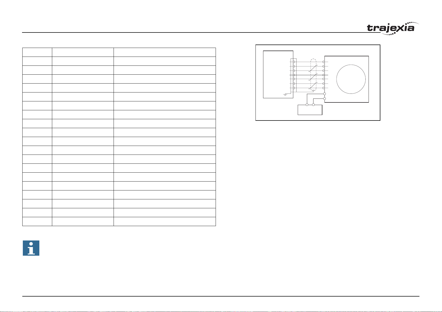
Hardware reference
1 PG0V Signal ground
2 PG0V Signal ground
3 PG0V Signal ground
4- -
5- -
6- -
NS115
CN4
1,2,3
fig. 39/i
PG0V
FA
16
/FA
17
FB
18
/FB
19
FC
14
/FC
15
GND
A
/A
B
/B
Z
/Z
External PG
7- -
8- -
9- -
10 - -
11 - -
12 - -
13 - -
14 FC Phase-C input +
15 /FC Phase-C input -
16 FA Phase-A input +
17 /FA Phase-A input -
18 FB Phase-B input +
19 /FB Phase-B input -
20 - -
Note
Make sure that shielded cable is used and that the shield is connected to the connector shell.
External
power supply
Revision 5.0
Relevant servo parameters related with the use of Trajexia:
HARDWARE REFERENCE MANUAL 80
Page 86

Hardware reference
Encoder gear ratio resolution
These two parameters define the units of the system in combination with
UNITS.
• Pn202: Gear ratio numerator. Default is 4, set to 1 to obtain the
maximum encoder resolution.
• Pn203: Gear ratio denominator. Default=1.
Absolute encoder
• Pn205= Number of multiturn limit. Default 65535. Set to suitable value in
combination with the encoder gear ratio and UNITS.
Full close encoder
• Pn002.3: 0=Disabled, 1=uses without Z, 2=uses with Z, 3=uses without
Z reverse rotation, 4= uses with Z reverse rotation.
• Pn206: Number of full-closed encoder pulses per revolution. Default
16384
Using the Servo Driver digital inputs with Trajexia
• Pn50A: Mapping of the forward limit switch (P_OT).
• Pn50B: Mapping of the reverse limit switch (N_OT).
• Pn511: Mapping of the registration inputs and zero point return
declaration.
• Pn81E: Mapping of the normal inputs.
For the overview of all possible settings and parameter values to map the
input signals from the Servo Driver to Trajexia, refer to the Trajexia
Programming manual, chapter “Mapping Servo Driver inputs and outputs”.
For the rest of the parameters and connections refer to the Sigma-II manual.
Related BASIC commands
The following BASIC commands are related to the MECHATROLINK-II
Servo Drivers Sigma-II series:
• ATYPE
Revision 5.0
• AXIS
• AXIS_ENABLE
• AXISSTATUS
HARDWARE REFERENCE MANUAL 81
Page 87

Hardware reference
• DRIVE_ALARM
• DRIVE_CLEAR
• DRIVE_CONTROL
• DRIVE_INPUTS
• DRIVE_MONITOR
• DRIVE_READ
• DRIVE_RESET
• DRIVE_STATUS
• DRIVE_WRITE
For more information, refer to the Trajexia Programming Manual.
3.5.9 MECHATROLINK-II Servo Drivers Sigma-V series
You can also connect a Sigma-V Servo Driver to a Trajexia system.
/i
Label Terminal/LED Description
A CHARGE Charge indicator
B L1, L2, L3 Main circuit power supply terminals
C L1, L2 Control power supply terminals
D B1, B2 Regenerative resistor connecting terminals
E 1, 2 DC reactor terminals for harmonic suppression
F U, V, W Servo motor terminals
G + Ground terminal
H CN6A/B MECHATROLINK-II bus connectors
I CN3 Connector for digital operator
J CN7 PC connector
K CN1 I/O signal connector
L CN8 Connector for safety function devices
M CN2 Encoder connector
N SW1 Rotary switch for MECHATROLINK-II address settings
O SW2 Dipswitches for MECHATROLINK-II communication settings
Revision 5.0
P Panel display
Q MECHATROLINK-II communication LED
A
B
C
D
E
F
G
CHARGE
L1
L2
L3
L1
L2
B1
B2
B3
1
2
U
V
W
fig. 40
C
H
N
6
A/B
1
0
2
F
3
E
4
D
5
C
ON
6
B
7
A
8
C
I
N
3
C
J
N
7
C
K
N
1
C
L
N
8
C
N
M
2
9
NPO
1
R
Q
HARDWARE REFERENCE MANUAL 82
Page 88

Hardware reference
Label Terminal/LED Description
R Power LED
Communication settings (SW2)
The 4 dipswitches configure the communication settings.
/i
Dipswitch Function Setting Description Factory
setting
1 Baud rate on 10 Mbps on
2 Data length on 32-byte data transmission on
3Address
range
off Addresses 40-4F off
on Addresses 50-5F
fig. 41
4 Reserved off Must always be set to off. on is not
used
Revision 5.0
off
1
HARDWARE REFERENCE MANUAL 83
Page 89
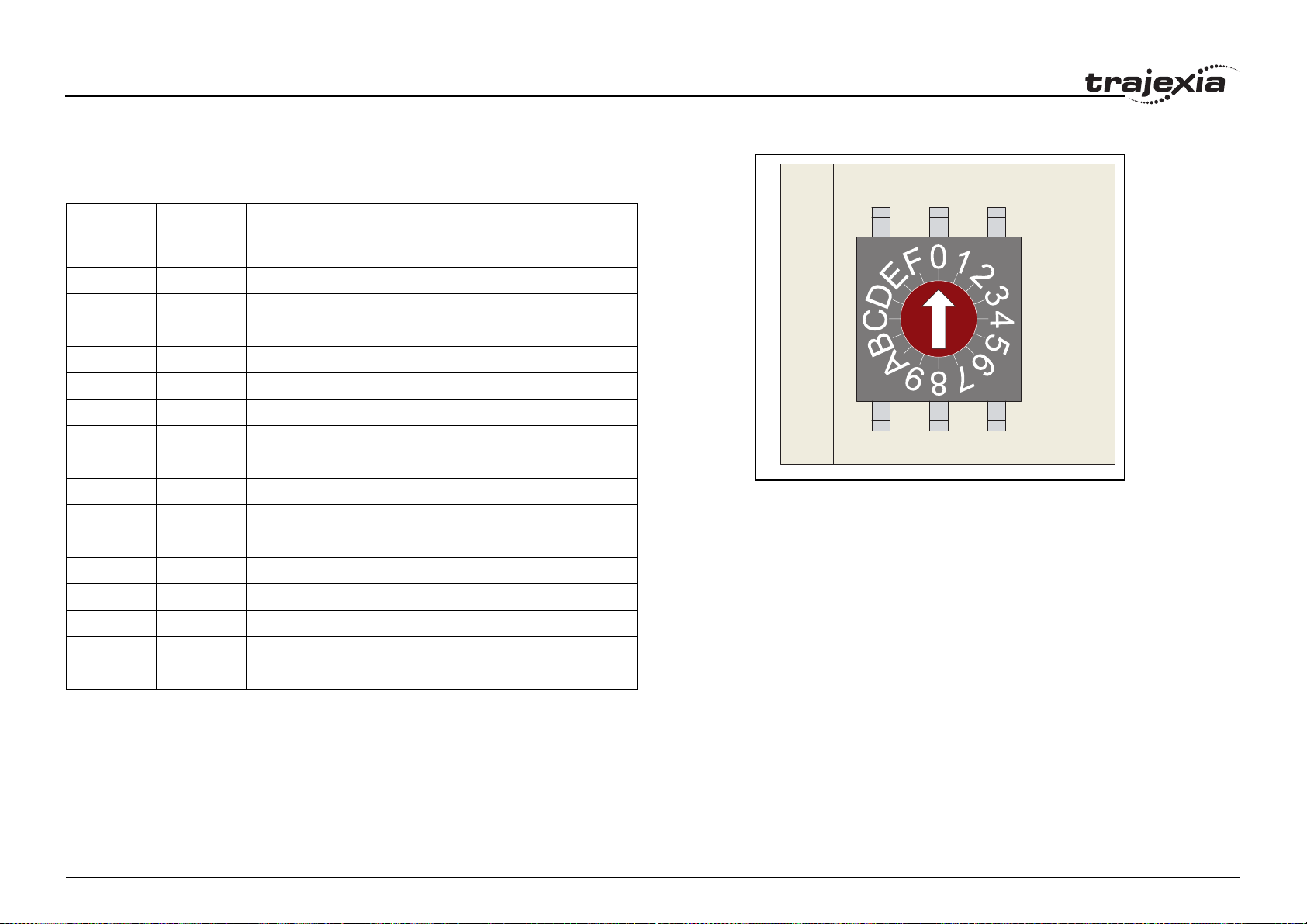
Hardware reference
Address settings (SW1)
Set the address selector of the Sigma-V Servo Driver to n (where n ranges
from 0 to F) to assign the following station address to it:
/i
fig. 42
Rotary
switch
number
1off41 0
2off42 1
3off43 2
4off44 3
5off45 4
6off46 5
7off47 6
8off48 7
9off49 8
Aoff4A 9
Boff4B 10
Coff4C 11
Doff4D 12
Eoff4E 13
Foff4F 14
Dipswitch 3 Station address Axis in motion controller
0on50 15
Do not use the addresses 40 and 51-5F. Use only the addresses 41-50.
Revision 5.0
HARDWARE REFERENCE MANUAL 84
Page 90

Hardware reference
LEDs
/i
LED Color Description
Charge indicator Orange Lit: main circuit power supply is on or internal
capacitor is charged
Not lit: no power supply and internal capacitor
is not charged
Power LED Green Lit: control power is supplied
Not lit: no control power
MECHATROLINK-II communication LED
Green Lit: communication active
Not lit: no communication
Panel display
The panel display is a 7-segment LED display. It indicates the status of the
Servo Driver.
The panel display has 3 display modes:
• Status display
The display shows the statuses listed in the table below.
/i
Display Description Remark
Baseblock Comes on when the motor current is shut off. Does not
come on when the Servo Driver is on
Rotation detection
(/TGON)
Reference input Comes on when a reference is being input
CONNECT Comes on during connection
Comes on when the motor speed is greater than the
value set in Pn502
Revision 5.0
HARDWARE REFERENCE MANUAL 85
Page 91
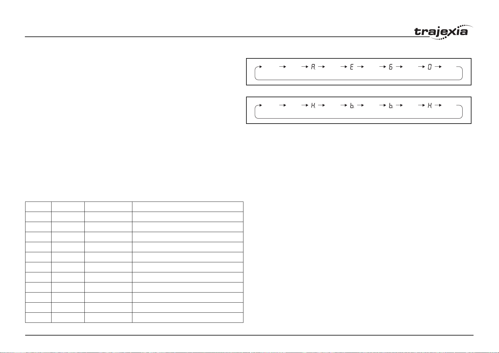
Hardware reference
• Alarm/warning
If an alarm or a warning occurs, the display shows the alarm code or the
warning code.
The figure shows an example of displaying alarm code A.E60.
• Test without motor
The display shows the sequence given in the figure if a test is executed
without a motor.
MECHATROLINK-II connectors (CN6A & CN6B)
Connect the Sigma-V Servo Driver to the MECHATROLINK-II network using
the CN6A and CN6B connectors. Use one of the MECHATROLINK-II
connectors to connect to the previous MECHATROLINK-II device or the
TJ1-ML__. Use the other MECHATROLINK-II connector to connect to the
next MECHATROLINK-II device, or to connect a MECHATROLINK-II
terminator.
CN1 I/O Signal connector
The table below shows the pin layout for the I/O signal connector (CN1).
/i
Status
Display
Status
Display
fig. 43
Unlit UnlitUnlit Unlit Unlit
fig. 44
Unlit UnlitUnlit Unlit Unlit
Pin I/O Signal Signal name
1 Output /BK+ (/SO1+) Brake interlock signal
2 Output /BK- (/SO1-) Brake interlock signal
3 Output ALM+ Servo alarm output signal
4 Output ALM- Servo alarm output signal
5 N/A N/A Not used
6 Input +24 V IN Control power supply for sequence signal
7 Input P-OT Forward run prohibited
8 Input N-OT Reverse run prohibited
9 Input /DEC Homing deceleration limit switch
Revision 5.0
10 Input /EXT1 External latch signal 1
11 Input /EXT2 External latch signal 2
1
1
HARDWARE REFERENCE MANUAL 86
Page 92
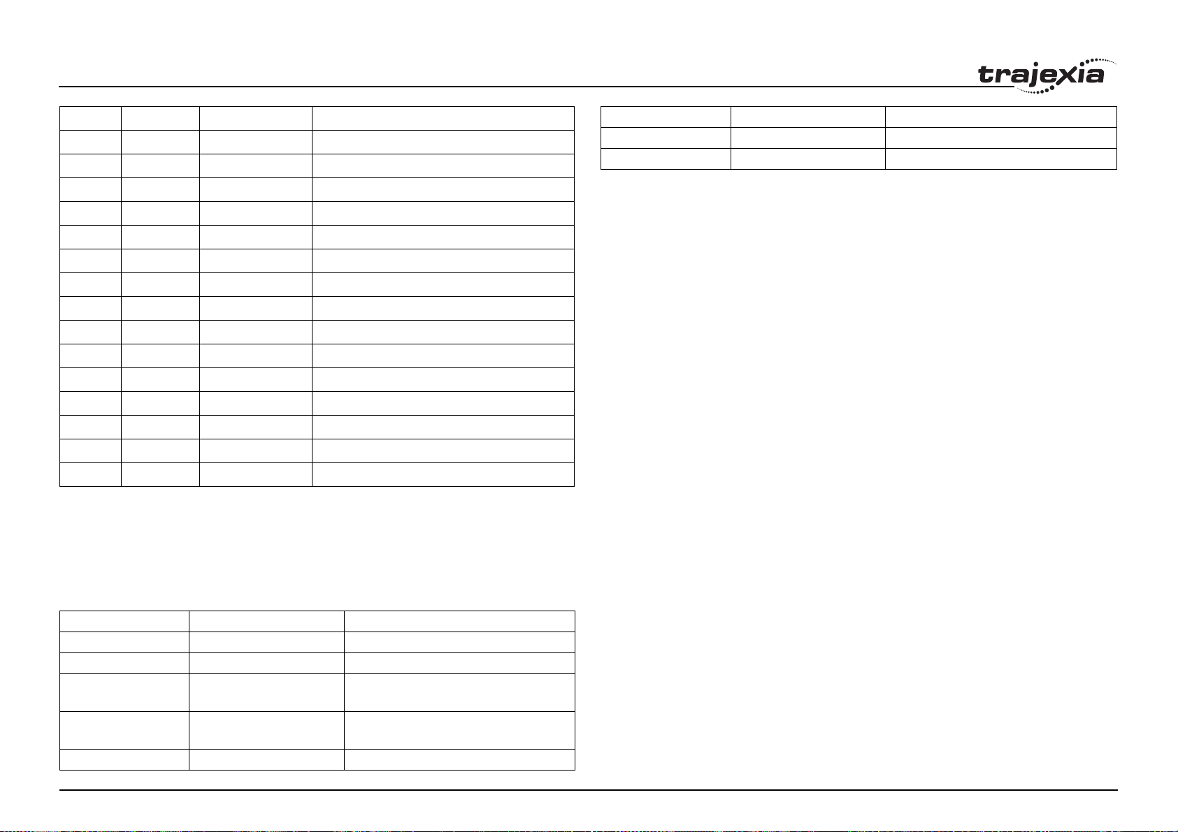
Hardware reference
Pin I/O Signal Signal name
12 Input /EXT3 External latch signal 3
13 Input /SIO General-purpose input signal
14 N/A N/A Not used
15 N/A N/A Not used
16 Output FG Signal ground
17 N/A N/A Not used
18 N/A N/A Not used
19 N/A N/A Not used
20 N/A N/A Not used
21 Input BAT (+) Battery (+) input signal
22 Input BAT (-) Battery (-) input signal
23 Output /SO2+ General-purpose output signal
24 Output /SO2- General-purpose output signal
25 Output /SO3+ General-purpose output signal
26 Output /SO3- General-purpose output signal
1
1. NPN only.
For more information, refer to the Sigma-V Series SERVOPACKs manual.
Pin Signal Description
6 /PS PG serial signal input (-)
Shell Shield -
Related BASIC commands
The following BASIC commands are related to the MECHATROLINK-II
Servo Drivers Sigma-V series:
• ATYPE
• AXIS
• AXIS_ENABLE
• AXISSTATUS
• DRIVE_ALARM
• DRIVE_CLEAR
• DRIVE_CONTROL
• DRIVE_INPUTS
• DRIVE_MONITOR
• DRIVE_READ
• DRIVE_RESET
• DRIVE_STATUS
• DRIVE_WRITE
For more information, refer to the Trajexia Programming Manual.
CN2 encoder connector
The tables below shows the pin layout for the Sigma-V encoder connector.
/i
Pin Signal Description
1 PG 5 V PG power supply +5 V
2 PG 0 V PG power supply 0 V
3 BAT (+) Battery (+)
(For an absolute encoder)
Revision 5.0
4 BAT (-) Battery (-)
(For an absolute encoder)
5 PS PG serial signal input (+)
HARDWARE REFERENCE MANUAL 87
Page 93

Hardware reference
3.5.10 MECHATROLINK-II Servo Drivers Junma series
You can also connect a Junma Servo Driver to a Trajexia system.
/i
Label Terminal/LED Description
A FIL Rotary switch for reference filter setting
B CN6A & CN6B MECHATROLINK-II bus connectors
C CN1 I/O signal connector
D CN2 Encoder input connector
E SW1 Rotary switch for MECHATROLINK-II address settings
F SW2 Dipswitches for MECHATROLINK-II communication settings
G RDY Servo status indicator
H ALM Alarm indicator
I COM MECHATROLINK-II communication status indicator
J CNA Connector for power supply
K CNB Connector for servo motor
LED indicators
/i
LED Description
COM Lit: MECHATROLINK-II communication in progress
Not lit: No MECHATROLINK-II communication
ALM Lit: An alarm occurred
Not lit: no alarm
RDY Lit: Power is on, standby for establishment of communication
Blinking: Servo ON status
A
B
C
D
fig. 45
COM
ALM
RDY
4
5
3
6
2
7
1
8
0
9
FIL
F
A
E
B
D
C
CN
6
A/B
CN
1
CN
2
PWR
L1
L2
J
CN
A
U
V
W
K
CN
B
4
5
3
6
2
7
1
8
0
9
A
F
ON
B
E
C
D
1
G
H
I
E
F
Revision 5.0
HARDWARE REFERENCE MANUAL 88
Page 94

Hardware reference
Communication settings (SW2)
The 4 dipswitches configure the communication settings.
/i
Dipswitch Function Setting Description
1 Reserved ON Must always be set to ON. OFF is not used
2 Data
length
3 Address
range
4Filter
setting
ON 32 bytes
OFF Addresses 40-4F
ON Addresses 50-5F
OFF Set the filter with the FIL rotary switch
ON Set the filter with Pn00A
fig. 46
1
Revision 5.0
HARDWARE REFERENCE MANUAL 89
Page 95

Hardware reference
Address settings (SW1)
Set the address selector of the Junma Servo Driver to n (where n ranges
from 0 to F) to assign the following station address to it:
/i
fig. 47
Rotary
switch
number
1off41 0
2off42 1
3off43 2
4off44 3
5off45 4
6off46 5
7off47 6
8off48 7
9off49 8
Aoff4A 9
Boff4B 10
Coff4C 11
Doff4D 12
Eoff4E 13
Foff4F 14
Dipswitch 3 Station address Axis in motion controller
0on50 15
Do not use the addresses 40 and 51-5F. Use only the addresses 41-50.
Revision 5.0
HARDWARE REFERENCE MANUAL 90
Page 96

Hardware reference
CN1 I/O Signal connector
The table below shows the pin layout for the I/O signal connector (CN1).
/i
fig. 48
Pin I/O Code Signal name
1 Input /EXT1 External latch
2 Input /DEC Homing deceleration
3 Input N_OT Reverse run prohibit
4 Input P_OT Forward run prohibit
5 Input +24VIN External input power supply
6 Input E-STP Emergency stop
7 Output SG-COM Output signal ground
8N/C
9N/C
10 N/C
11 N/C
12 Output ALM Servo alarm
13 Output /BK Brake
14 N/C
Shell - - FG
MECHATROLINK-II connectors (CN6A & CN6B)
Connect the Junma Servo Driver to the MECHATROLINK-II network using
the CN6A and CN6B connectors. Use one of the MECHATROLINK-II
connectors to connect to the previous MECHATROLINK-II device or the
TJ1-ML__. Use the other MECHATROLINK-II connector to connect to the
next MECHATROLINK-II device, or to connect a MECHATROLINK-II
terminator.
891011121314
1234567
Revision 5.0
HARDWARE REFERENCE MANUAL 91
Page 97

Hardware reference
CN2 encoder input connector
The tables below shows the pin layout for the Junma Servo Driver encoder
connector.
/i
Pin Signal
1PG5V
2 PG0V (GND)
3Phase A (+)
4 Phase A (-)
5Phase B (+)
6 Phase B (-)
7 Phase /Z
8Phase U
9Phase V
10 Phase W
Shell -
CNA power supply connector
The tables below shows the pin layout for the CNA power supply connector.
/i
Pin Signal Name
1 L1 Power supply terminal
2 L2 Power supply terminal
3 + Regenerative unit connection terminal
4 - Regenerative unit connection terminal
fig. 49
97531
46810
2
fig. 50
A
N
1
2
3
4321
Revision 5.0
HARDWARE REFERENCE MANUAL 92
4
Page 98

Hardware reference
CNB servo motor connector
The tables below shows the pin layout for the CNB servo motor connector.
/i
Pin Signal Name
1 U Phase U
2 V Phase V
3 W Phase W
4N/C
Related BASIC commands
The following BASIC commands are related to the MECHATROLINK-II
Servo Drivers Junma series:
• ATYPE
• AXIS
• AXIS_ENABLE
• AXISSTATUS
• DRIVE_ALARM
• DRIVE_CLEAR
• DRIVE_CONTROL
• DRIVE_INPUTS
• DRIVE_MONITOR
• DRIVE_READ
• DRIVE_RESET
• DRIVE_STATUS
• DRIVE_WRITE
Revision 5.0
fig. 51
1
A
1
N
2
2
34
3
4
For more information, refer to the Trajexia Programming Manual.
HARDWARE REFERENCE MANUAL 93
Page 99

Hardware reference
3.5.11 MECHATROLINK-II Servo Drivers G-series
You can also connect a G-Series Servo Driver to a Trajexia system.
/i
Label Terminal/LED Description
A SP, IM, G Analog monitor check pins
B L1, L2, L3 Main-circuit power terminals
C L1C, L2C Control-circuit power terminals
D B1, B2, B3 External Regeneration Resistor connection terminals
E U, V, W Servomotor connection terminals
F CN2 Protective ground terminals
G --- Display area
H --- Rotary switches
I COM MECHATROLINK-II communications status LED indicator
J CN3 RS-232 communications connector
K CN6A, CN6B MECHATROLINK-II communications connector
L CN1 Control I/O connector
M CN2 Encoder connector
LED indicators
/i
LED Description
COM Lit: MECHATROLINK-II communication in progress
Not lit: No MECHATROLINK-II communication
fig. 52
G
H
AC SERVO DRIVE
ADR
0
0
1
1
9
2
2
8
3
3
7
4
6
5
X10
COM
A
SP
IM
G
X1
B
C
D
I
J
K
L
E
F
M
Revision 5.0
HARDWARE REFERENCE MANUAL 94
Page 100

Hardware reference
Address settings (SW1)
Set the address selector of the G-series Servo Driver to the required node
address by using the X1 (right) and X10 (left) rotary switches.
The setting range for the node address setting rotary switch is 1 to 31. The
actual station address used on the network will be the sum of the rotary
switch setting and the offset value of 40h. These node addresses
correspond to axis numbers 0 (node address = 1) to 15 (node address = 16).
Note
The node address is only loaded once when the control power
supply is turned ON. Changes made after turning the power ON
will not be applied until the power is turned ON next time. Do not
change the rotary switch setting after turning the power ON
7-segment LED (2 digits)
Analog monitor pins
Speed monitor
SP:
Torque monitor
IM:
Signal ground
G:
SP
IM
fig. 53
AC SERVO DRIVER
ADR
0
1
9
2
8
3
7
X10
COM
Rotary switches for
setting a node
address
0
1
2
3
4
6
5
X1
MECHATROLINK-II
communications
status LED
indicator (COM)
Note
G
If the rotary switch setting is not between 1 and 31, a node
address setting error (alarm code 82) will occur.
Revision 5.0
HARDWARE REFERENCE MANUAL 95
 Loading...