

Page 1

T20 Pendant
User's Manual
I601-E-04
Page 2

Copyright Notice
The information contained herein is the property of OMRON, and shall not be reproduced in whole or in
part without prior written approval of OMRON The information herein is subject to change without
notice and should not be construed as a commitment by OMRON The documentation is periodically
reviewed and revised.
OMRON, assumes no responsibility for any errors or omissions in the documentation.
Copyright © 2020 by OMRON Corporation
Any trademarks from other companies used in this publication
are the property of those respective companies.
Created in the United States of America
Page 3

Table of Contents
Chapter 1: Introduction 9
1.1 Product Description
Features 9
System Compatibility 9
1.2 Proper Handling of the Pendant
1.3 How Can I Get Help?
Related Manuals 10
10
10
Chapter 2: Safety 13
2.1 Dangers, Warnings, Cautions
Alert Icons 13
Special Information 13
2.2 What to Do in an Emergency or Abnormal Situation
Stopping the Robot 14
Fire Response 14
2.3 Safety Precautions
2.4 Additional Safety Information
Manufacturer’s Declarations 15
Robot Safety Guide 15
Emergency Stop Circuit and Buttons 15
Safety Standard Compliance 15
2.5 Disposal
13
13
14
15
16
9
Chapter 3: Installation and Setup 17
3.1 Transport and Storage
3.2 Unpacking the Pendant
3.3 Repacking for Shipment
3.4 Operating Environment
3.5 Installation
Chapter 4: Operation 23
4.1 Using the Pendant Controls and Indicators
Keypad Functions 25
4.2 Enable Switch
4.3 Turning Power ON and OFF
Turning Robot Power ON 28
10433-000 Rev. H T20 Pendant User's Manual 3
17
17
17
18
18
23
27
28
Page 4

Table of Contents
Turning OFF Power from the T20 Pendant 29
4.4 User Interface Operation
User Interface Controls 29
User Interface Flow Diagram 30
Displaying the Home Screens 33
4.5 Using Jog Mode
COMP Mode 35
Joint Mode 35
World Mode 36
Tool Mode 37
Free Mode 38
4.6 Speed Control
4.7 Position Display
4.8 Smart Locations
4.9 Available Frames
Enable Frame-Based Jogging 42
A Note about Frame-mode Jogging 42
4.10 Available Tools
4.11 Location Teaching
Adding Approach Distance 46
Using Jog To 46
Align 47
4.12 I/O Signals
4.13 Displaying and Clearing Errors
29
34
38
39
40
41
43
43
47
49
Chapter 5: Maintenance 51
5.1 The System Maintenance Screen
5.2 Setting the Screen Saver
5.3 Setting the Initial Speed
5.4 Enabling Smart Locations
5.5 Setting the Approach Distance
5.6 Enabling Pendant Messages
5.7 Displaying System Information
5.8 Displaying Recent Errors
5.9 Updating the Pendant Firmware
5.10 Loss of Communication
5.11 Cleaning
5.12 Periodic Maintenance
4 T20 Pendant User's Manual 10433-000 Rev. H
51
52
53
53
53
54
54
55
56
58
58
58
Page 5

Table of Contents
Chapter 6: Technical Specifications 59
6.1 Dimension Drawings
6.2 Pendant Specifications
59
59
10433-000 Rev. H T20 Pendant User's Manual 5
Page 6

Page 7
Revision History
Revision
code
A May, 2012 Original production release.
B July, 2013 Updates for the new user interface
C March, 2014
D May, 2016
E June, 2016
F March, 2019
G July, 2020 Update for NJ-series Robot Integrated CPU Unit.
H August, 2020 Minor corrections and revisions.
Date Revised Content
Added references to eV+ Language User's Guide.
General updates .
Minor specification updates
Minor updates for translation.
10433-000 Rev. H T20 Pendant User's Manual 7
Page 8

Page 9

This manual covers the setup, operation, and user maintenance of the T20 pendant.
1.1 Product Description
The T20 pendant provides a user interface and teach pendant in an ergonomic and rugged
package. The T20 pendant is designed for right or left-handed use. All gripping and holding
positions enable comfortable and fatigue-free operation.
Features
The safety features include:
l
Emergency stop switch (dual-channel circuit)
l
Three-position enable switch that prevents pendant input or robot motion when the
switch is not engaged
The software features include the ability to:
l
Control the robot by enabling and disabling power and jogging the robot
The T20 pendant can only move one robot at a time, even if multiple robots are connected to a SmartController EX, and the pendant is connected to the SmartController EX.
Chapter 1: Introduction
If there is no SmartController EX in the system, the pendant can only be connected to a
single robot at any given time. A single pendant connection can only control a single
robot for systems using an iCS-ECAT or eCS-ECAT controller.
l
Teach locations
l
Use Smart Locations, which allow you to work with locations through the Frame and
Tool screens
l
Display robot position, system status, system identification, and error messages
l
Display and exchange digital I/O with the robot
The pendant cannot exchange digital I/O over the EtherCAT network.
l
Debug (and teach)V+programs using Step mode
System Compatibility
The T20 pendant works with a robot that is controlled by a control system that runs eV+.
The iCS and eCS robots require a T20 with firmware v3.x+.
A T20 with v3.x firmware will also support eAIB, SmartController EX, eMB-40, and eMB-60
controllers running eV+ 2.4 or later. A T20 pendant running v2.x firmware must be upgraded
to at least 2.3.3.14 firmware to work with eV+ 2.4 or later.
NOTE: A T20 pendant with 2.x firmware cannot be upgraded to 3.x firmware.
10433-000 Rev. H T20 Pendant User's Manual 9
Page 10
1.2 Proper Handling of the Pendant
!
1.2 Proper Handling of the Pendant
To avoid malfunctions or damage through improper handling, and possible voiding of the
warranty, follow these instructions during operation.
l
When you are not using the T20 pendant, place it in a safe location and clear of the
robot working envelope.
l
Never place the T20 pendant with the display screen facing down, to avoid damaging
the buttons or display.
l
Never place the T20 pendant on an unstable surface. It could fall to the ground and be
damaged.
l
Never place the T20 pendant close to heat sources or in direct sunlight.
l
Avoid exposing the T20 pendant to mechanical vibrations, excessive dust, humidity, or
strong magnetic fields.
l
Never clean the T20 pendant display screen or other surfaces with solvents, abrasive
cleaners, or scrubbing sponges.
l
Make sure that no foreign objects or liquids can penetrate into the T20 pendant.
WARNING: When the cable entrance cover is removed, the T20 pendant is
sensitive to electrostatic discharge.
1.3 How Can I Get Help?
Refer to the corporate website:
http://www.ia.omron.com
Related Manuals
This guide covers the installation, operation, and maintenance of the T20 pendant. There are
additional manuals that cover programming the system, reconfiguring installed components,
and adding other optional components. See the table that follows. These manuals are also
available on the software media shipped with each robot system.
Manual Description
Robot Safety Guide (Cat. No. I590) Contains safety information for our
Table 1-1. Related Manuals
robots.
SmartController EX User's Guide (Cat.
No. I602)
Contains complete information on
the installation and operation of the
SmartController EX motion controller.
10 T20 Pendant User's Manual 10433-000 Rev. H
Page 11

Chapter 1: Introduction
Manual Description
ACE User's Guide (Cat. No. I603) Describes the ACE software envir-
onment and use with a control system. This documentation is included
in the ACE software installation.
eV+ Language User's Guide (Cat. No.
I604)
eV+ Language References Guide (Cat.
No. I605)
eV+ Operating System User's Guide
(Cat. No. I606)
Describes the eV+ language and programming of a control system.
Detailed descriptions of the
keywords in the eV+ language.
Describes the eV+ operating system.
Loading, storing, and executing programs are covered in this guide.
eV+ Operating System Reference Guide
(Cat. No. I607)
Describes the eV+ operating system
commands (known as monitor commands).
eV+3 User's Manual (Cat. No. I651) Describes the eV+ language and pro-
gramming of a control system for
eV+ version 3.x and later.
eV+3 Keyword Reference Manual (Cat.
No. I652)
Detailed descriptions of the
keywords in the eV+ language for
eV+ version 3.x and later.
NJ-series Robot Integrated CPU Unit
User's Manual (Cat. No. O037)
Describes the settings and operation
of the CPU Unit and programming
concepts for OMRON robot control.
Sysmac Studio Version 1 Operation
Manual (Cat. No. W504)
Describes the operating procedures
of the Sysmac Studio.
Robot user's guide User Guide for the robot in use.
Sysmac Studio Integrated Robot System
Control Function Operation Manual
(Cat. No. W595)
Learning about the operating procedures and functions of the Sysmac
Studio to configure Robot Integrated
System using Robot Integrated CPU
Unit.
10433-000 Rev. H T20 Pendant User's Manual 11
Page 12

Page 13
2.1 Dangers, Warnings, Cautions
!
!
!
The following levels of alert notation are used in this manual, in descending order of importance.
WARNING: Identifies a potentially hazardous situation which, if not avoided,
will result in minor or moderate injury, and might result in serious injury, fatality, or significant property damage.
CAUTION: Identifies a potentially hazardous situation which, if not avoided,
might result in minor injury, moderate injury, or property damage.
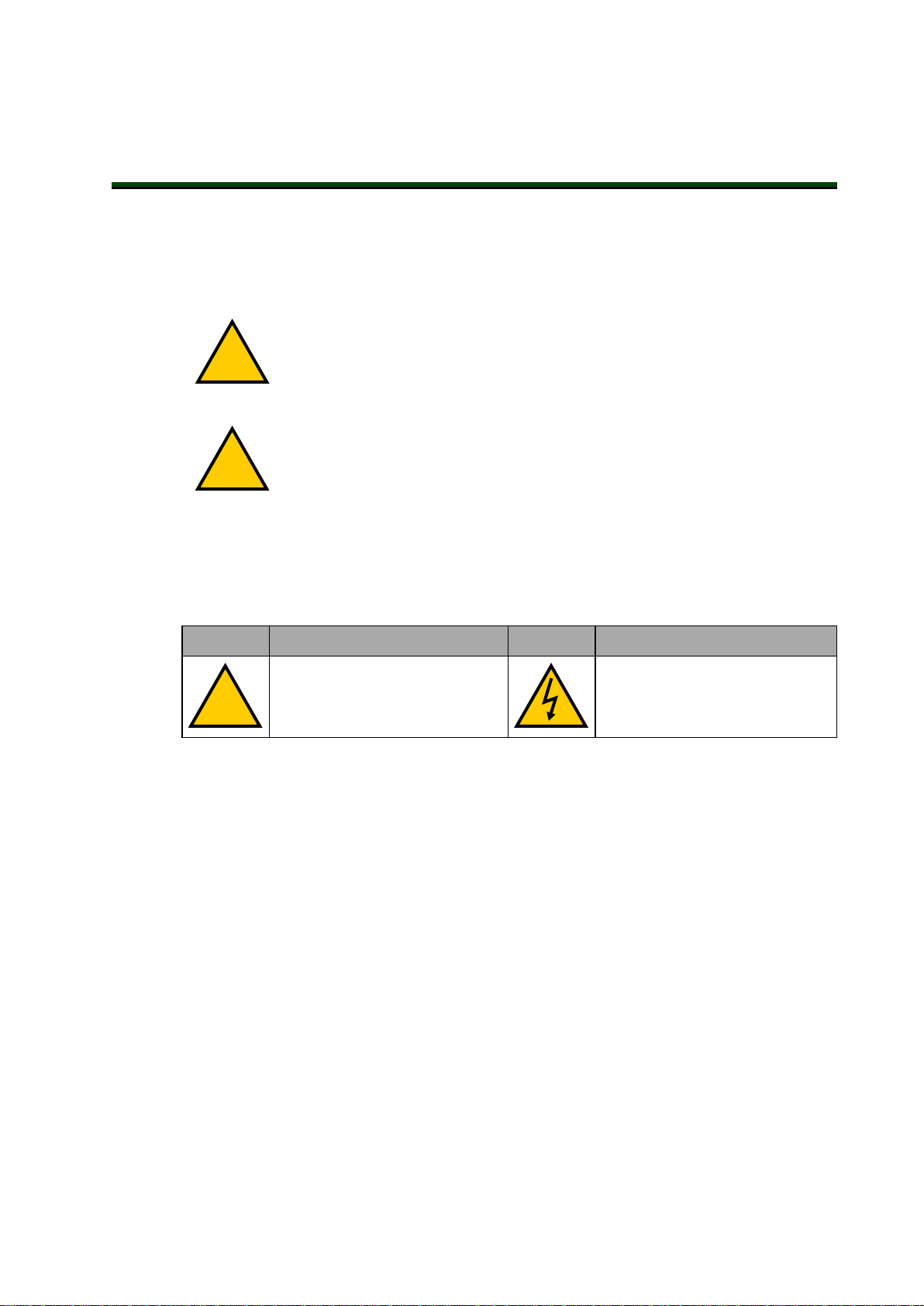
Alert Icons
The icon that starts each alert can be used to indicate the type of hazard. These will be used
with the appropriate signal word - Danger, Warning, or Caution - to indicate the severity of the
hazard. The text following the signal word will specify what the risk is, and how to avoid it.
Chapter 2: Safety
Icon Meaning Icon Meaning
This is a generic alert icon. Any
specifics on the risk will be in the
text following the signal word.
Special Information
There are several types of notation used to call out special information.
IMPORTANT: Information to ensure safe use of the product.
NOTE: Information for more effective use of the product.
Additional Information: Offers helpful tips, recommendations, and best prac-
tices.
Version Information: Information on differences in specifications for different
versions of hardware or software.
2.2 What to Do in an Emergency or Abnormal Situation
This identifies a hazardous electrical situation.
10433-000 Rev. H T20 Pendant User's Manual 13
Page 14
2.3 Safety Precautions
!
Stopping the Robot
Press any E-Stop button (a red push-button on a yellow background) and then follow the
internal procedures of your company or organization for an emergency situation.
Fire Response
If a fire occurs, use CO2to extinguish the fire.
2.3 Safety Precautions
WARNING: ELECTROCUTIONRISK
During maintenance, disconnect AC power from the robot, and install a lockout tag-out to prevent anyone from reconnecting power.
WARNING: PERSONALINJURYORPROPERTYDAMAGERISK
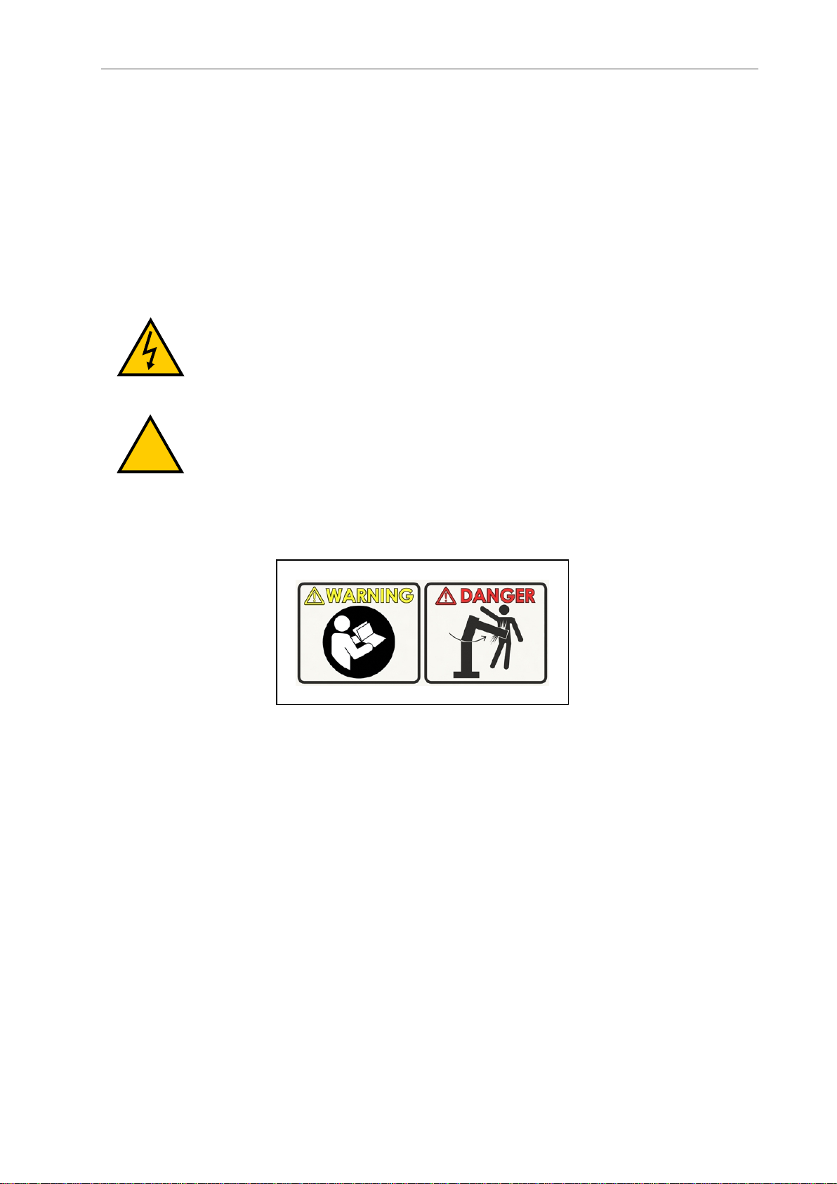
A robot can cause serious injury or death, or damage to itself and other equipment, if the safety precautions in this manual are not observed:
l
All personnel who install, operate, teach, program, or maintain the system must read
this guide, read the Robot Safety Guide (Cat. No. I590), and complete a training course for
their responsibilities in regard to the robot.
Figure 2-1. Read Manual and Impact Warning Labels
l
All personnel who design the robot system must read this guide, read the Robot Safety
Guide (Cat. No. I590), and must comply with all local and national safety regulations for
the location in which the robot is installed.
l
The robot system must not be used for purposes other than described in the robot user’s
guide. Contact your local OMRON representative if you are not sure of the suitability for
your application.
l
The user is responsible for providing safety barriers around the robot to prevent anyone
from accidentally coming into contact with the robot when it is in motion.
l
Lock out and tag out power to the robot and its power supply before performing any
maintenance on the robot.
14 T20 Pendant User's Manual 10433-000 Rev. H
Page 15

2.4 Additional Safety Information
We provide other sources for more safety information:
Manufacturer’s Declarations
This lists the standards with which our robots and controllers comply. The Manufacturer’s
Declarations are in the Manufacturer's Declarations Guide (p/n 18305-000).
Robot Safety Guide
The Robot Safety Guide (Cat. No. I590) provides detailed information on safety for our robots. It
also gives resources for more information on relevant standards. It ships with each robot.
Emergency Stop Circuit and Buttons
The E-Stop provided complies with ISO 10218-1 (Clause 5.5.2), with stop category 1 (per IEC
60204). The E-stop button complies with ISO 13850. The E-Stop meets the requirements of PL-d
per ISO 13849.
Chapter 2: Safety
Safety Standard Compliance
The protective stop category for the pendant enable switch is category 1, which complies with
the requirements of ISO 10218-1.
The pendant is designed in accordance with the requirements of IEC 60204-1 and ISO 13849.
The E-Stop button is ISO 13850.
The robot control system is designed so that when the robot is placed under pendant control,
initiation of robot motion or control selection from any other source is prevented.
This is in compliance with ISO 10218-1.
10433-000 Rev. H T20 Pendant User's Manual 15
Page 16

2.5 Disposal
2.5 Disposal
Customers can contribute to resource conservation and protecting the environment by the
proper disposal of WEEE (Waste Electronics and Electrical Equipment). All electrical and electronic products should be disposed of separately from the municipal waste system via designated collection facilities. For information about disposal of your old equipment, contact your
local OMRON representative.
Dispose of in accordance with applicable regulations.
16 T20 Pendant User's Manual 10433-000 Rev. H
Page 17

Chapter 3: Installation and Setup
This chapter covers the installation and setup of the T20 pendant.
3.1 Transport and Storage
The T20 pendant must be shipped and stored in a temperature-controlled environment, within
the range –25 to +60°C (-13 to 140°F). The recommended humidity range is 5% to 95%, non-condensing. It should be shipped and stored in the original packaging, which is designed to prevent damage from normal shock and vibration. You should protect the packaging from
excessive shock and vibration. The pendant must always be stored and shipped in a clean,
dry area that is free from condensation.
The T20 pendant weighs 480 g (1.1 lb) without the adapter cable installed.
3.2 Unpacking the Pendant
Carefully inspect the shipping packages for evidence of damage during transit. If any damage
is indicated, request that the carrier’s agent be present at the time the container is unpacked.
Before signing the carrier’s delivery sheet, compare the actual items received (not just the packing slip) with your equipment purchase order. Verify that all items are present and that the
shipment is correct and free of visible damage.
l
If the items received do not match the packing slip, or are damaged, do not sign the
receipt. Contact your local OMRON representative as soon as possible.
l
If the items received do not match your order, please contact your local OMRON representative immediately.
l
Retain all containers and packaging materials. These items may be necessary to settle
claims.
Remove the pendant from its box and place it on its back on a flat surface.
3.3 Repacking for Shipment
If the pendant needs to be shipped, reverse the steps in the installation procedures in this
chapter. Reuse all original packing containers and materials and follow all safety notes used
for installation. Improper packaging for shipment will void your warranty.
10433-000 Rev. H T20 Pendant User's Manual 17
Page 18

3.4 Operating Environment
!
3.4 Operating Environment
The T20 pendant is designed to operate in the following environment:
l
Temperature: 0 to 45°C (32 to 113°F)
l
Humidity: 0% to 95%, non-condensing
CAUTION: Do not use the T20 pendant in hazardous environments (explosive gas, water, dust, oil, or mist), in mining operations, or outdoors. It has an IP
rating of IP65.
3.5 Installation
The T20 pendant can be used with any robot system using eV+. This may be attached to a
single robot or through a SmartController EX motion controller. A Front Panel is required in
either case.
Note the following points:
l
The E-Stop buttons on the Front Panel and T20 pendant both function and are individually detected.
l
The high-power-enable buttons on both devices function independently. The button on
either device can enable/disable power on the system.
l
In the legacy system there is generally a single controller (SmartController EX) and the
pendant is connected to this. If multiple robots are connected to the controller, then a
single pendant can be used to control each of them, one at a time. In the new (EtherCAT) system (NJ-series Robot Integrated CPU unit), the pendant needs to be plugged directly into the robot in order to control it, even if other robots are on the EtherCAT
network.
There can be as many pendants in the system as there are robots. Therefore, each
pendant is only controlling the robot it is connected to. It won’t be possible to connect
to, select, or control any other robot (other than the directly-connected robot) with the
pendant.
About Jumper Plugs
There are two jumpers, or bypass plugs, that can be used with a T20 pendant system. One is a
screw-to-lock T20 Pendant Bypass Plug (P/N 10048-000) for the pendant adapter cable,
included with the T20 pendant kit. The other is an XMCP jumper plug (P/N 10052-000)
included with the XSYSTEMcable assembly.
The reason for the jumper plugs is that the pendant emergency stop switch and the enable
switch are wired into the system emergency stop circuitry. If the T20 is not connected and
there is no jumper plug in the T20 cable, the system emergency stop circuitry will see this as
an E-Stop having been activated, and you cannot enable high power.
To prevent this, when either the pendant cable or the adapter cable will be unplugged, the corresponding jumper plug must be installed.
See the connection diagrams that follow.
18 T20 Pendant User's Manual 10433-000 Rev. H
Page 19
Chapter 3: Installation and Setup
A
C
B
E
D
21
ON
INOUT ID
XSYSTEM
DC
IN
24V
AC
1
200-
240V
GND
XIO
XBELTIO
NX
OP SV
3P
RUN
ERR
FS
x256
x16
x1
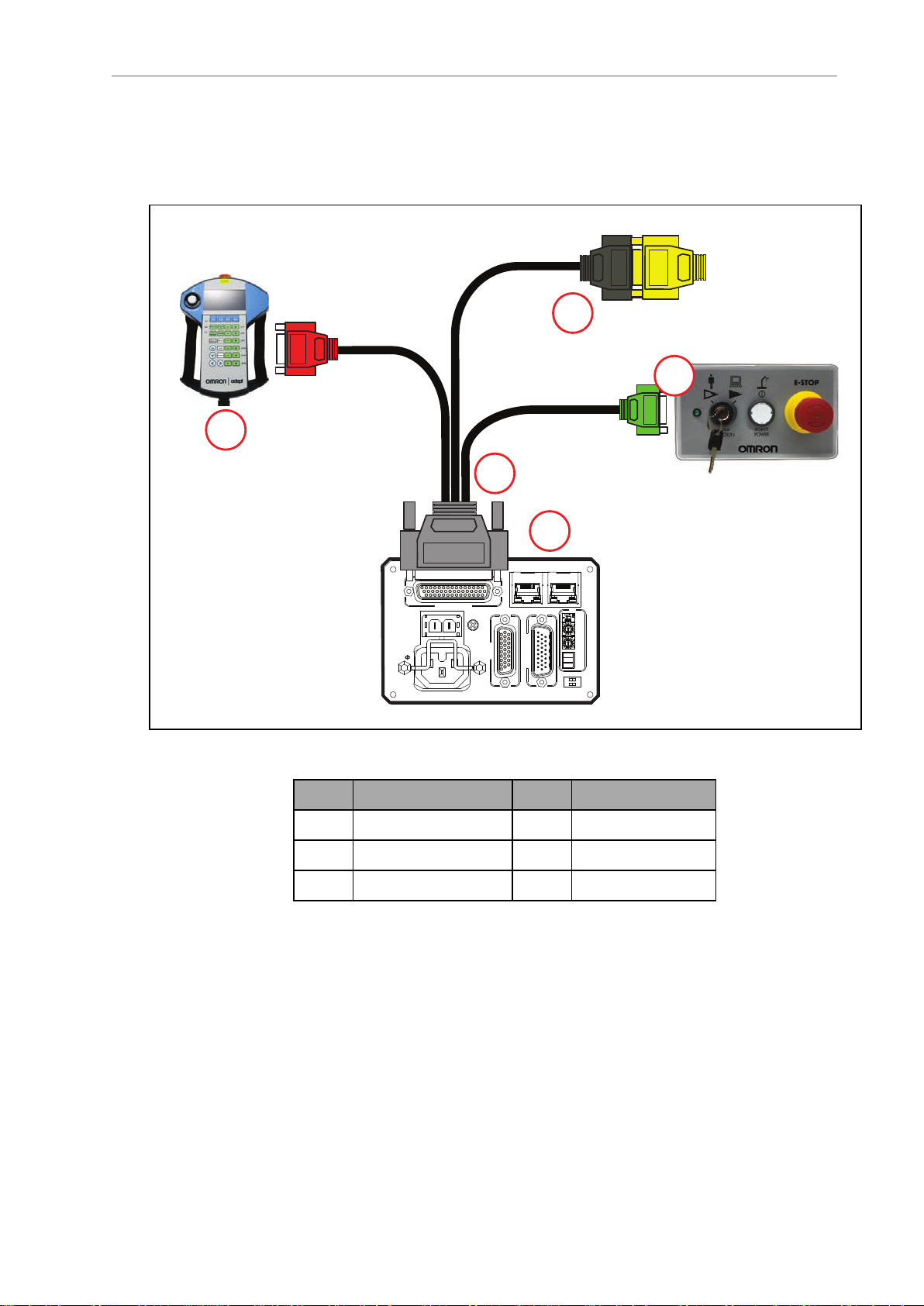
Installation without a SmartController EX
The following figure and table show a Front Panel and an T20 pendant connected to an EtherCAT robot. See your robot User's Guide for additional information.
Figure 3-1. Pendant and Front Panel Installation (eCobra EtherCAT Version Shown)
Letter Meaning Letter Meaning
A T20 Pendant D Front Panel
B XSYSTEM Cable E XUSR, with Jumper
C Robot Interface Panel
NOTE: A Front Panel or Front Panel Jumper Plug must be connected to
theeAIBXSYSTEMCable Assembly. A T20 Pendant, T20 Pendant Bypass Plug,
or XMCPJumper Plug must be connected to the eAIBXSYSTEMCable
Assembly.
10433-000 Rev. H T20 Pendant User's Manual 19
Page 20

3.5 Installation
STOP
R
T20
Pendant
SmartController EX
XMCP PLUG
10052-000
1
2
4
3
5
7
6
XUSR PLUG
04736-000
8
Installation with a SmartController EX
The following figure shows a Front Panel and an T20 pendant connected to a SmartController
EX motion controller. See the SmartController EX User's Guide (Cat. No. I602) for additional
information.
Figure 3-2. Pendant and Front Panel Installation with SmartController EX
NOTE: The cutout hole for the bypass plug should be Ø25+0.1 mm. The maximum wall thickness through which this hole is cut is 6.5 mm.
20 T20 Pendant User's Manual 10433-000 Rev. H
Page 21

Chapter 3: Installation and Setup
Table 3-1. Pendant and Front Panel Item Descriptions
Item Description Part Number
1 Front Panel 90356-10358
2 Front Panel Cable (3 m) 10356-10500
3 Front Panel Jumper Plug 04736-000
4 T20Pendant Kit 10046-010
5 T20 Pendant Assembly 10054-010
6 T20 Pendant Adapter Cable
(3 m)
7 T20 Pendant Bypass Plug 10048-000
8 XMCPJumper Plug 10052-000
10051-003
NOTE: Items 1 and 2 are included with most OMRON fixed robots. Items 3 and
8 are included with the SmartController EX. Item 4 includes items 5, 6, and 7.
NOTE: A Front Panel or Front Panel Jumper Plug must be connected to
theXSYSTEM XFP cable or to the SmartController EX. A T20 Pendant, T20 Pendant Bypass Plug, or XMCPJumper Plug must also be connected.
10433-000 Rev. H T20 Pendant User's Manual 21
Page 22

Page 23

Chapter 4: Operation
1
2
7
6
5
4
3
This chapter describes how to operate the T20 pendant. Before proceeding, you need to perform
the steps covered in the Installation and Setup chapter.
4.1 Using the Pendant Controls and Indicators
Use the following diagram to understand the Pendant controls and indicators
10433-000 Rev. H T20 Pendant User's Manual 23
Figure 4-1. T20 Pendant Controls and Indicators
Page 24

4.1 Using the Pendant Controls and Indicators
Table 4-1. T20 Pendant Control and Indicator Descriptions
Item Description
1 Display Screen
2
E-StopButton
Press to stop program execution and turn off high power immediately. If the robot is
equipped with brakes, activates the brakes.
3
Robot Power Button andLight
Press to toggle between high power ONand OFF. Unlike the emergency stop switch,
when turning OFF high power, a controlled stop is initiated, where the robot is decelerated under software control. After the robot has stopped, power is turned OFF.
When robot power is ON, this button is lit.
4
ACELED
When lit, indicates that the pendant is communicating.
5
ERRLED (Error)
When lit, indicates that an error has occurred.
6
JOGLED
When lit, indicates that the Joint/Axis control buttons are available to move the robot.
Also indicates that the system is not in COMP mode.
7 Keypad (Refer to Keypad Functions in the next section for more information)
24 T20 Pendant User's Manual 10433-000 Rev. H
Page 25

Keypad Functions
1
2
8
7
6
5
4
3
10
9
Chapter 4: Operation
Figure 4-2. Keypad Functions
Table 4-2. Keypad Descriptions
Item Description
1
SPEED + and SPEED - Buttons
Press to increase or decrease the robot speed as a percentage of the maximum monitor speed (COMP mode) or jog speed (non-COMP modes). The currently set speed is
displayed in the Speed indicator on the right side of the display screen.
2
10433-000 Rev. H T20 Pendant User's Manual 25
SLOW Button
Press to toggle between slow speed and normal speed. While slow speed is active,
press SPEED + or SPEED - to select a robot speed within the slow speed range,
which is from 0 to 20% of the normal robot speed. Press the SLOW button again to
return to normal speed.
Page 26

4.1 Using the Pendant Controls and Indicators
Item Description
3
JOG MODE Button
Press to cycle through COMP, Joint, World, Tool, or Free modes, and then return to
COMP mode. The currently selected mode is displayed in the Jog Mode indicator on
the left side of the display screen. A prolonged press on this button will change the
mode back to COMP.
4
MENU Button
Press to display the Home 1 screen.
5
SELECT ROBOT Button
When more than one robot is connected to a SmartController EX, press to cycle
through the connected robots. The currently selected robot is displayed in the Selected
Robot indicator on the display screen.
The T20 pendant can move multiple robots independently and sequentially, but cannot move multiple robots simultaneously.
6
OK Button
Press to select a setting to be changed, to implement a change, or to clear an error
message.
7
CANCEL Button
Press to return to the previous screen or to clear an error message.
8
9
10
Arrow Buttons
Press to make selections or to scroll through lists.
F1 - F4 Function Buttons
When using the display screen, press the function button (F1 to F4) that is under the
soft key you want to select. For example, from the Home 1 screen, press F1 to select
the Disp (Display) soft key.
Joint / Axis Control Buttons
Press a '+' button to move a joint or a Cartesian coordinate in the positive direction.
Press a '-' button to move in the negative direction. These buttons work all the time
while power is on and a jog mode is selected. Multiple joints or Cartesian coordinates can be moved simultaneously by pressing multiple buttons.
26 T20 Pendant User's Manual 10433-000 Rev. H
Page 27

4.2 Enable Switch
!
The pendant is equipped with a 3-position enable switch. The enable switch is located on the
back of the pendant, as shown in the following figure.
Chapter 4: Operation
WARNING: Improper use of the pendant can cause hazards. Ensure that you
always use the pendant properly, following the instructions in this manual.
Figure 4-3. 3-Position Enable Switch (Circled)
The full-out and full-in positions disable all output, as shown in the following table. In order
to enable high power in Manual mode, the switch must be activated. For details, see Turning
Robot Power ON on page 28.
Table 4-3. Enable Switch Positions on Pendant
Function Switch Position
Home Not pressed (out) Open
Enable Partially pressed (half-way, in middle position) Closed
Panic Fully pressed (in) Open
10433-000 Rev. H T20 Pendant User's Manual 27
Switch
Contacts
Page 28

4.3 Turning Power ON and OFF
4.3 Turning Power ON and OFF
This section discusses how to turn the power on and off in both auto and manual modes, as
well as after an E-Stop is pressed.
NOTE: When power is disabled, the pendant automatically changes to COMP
mode, and cannot change out of COMP mode. The Power button is functional
even when the screen saver is on. Pressing any other button only clears the
screen saver.
Turning Robot Power ON
The Robot Power light uses the same blinking pattern as the Front Panel: Fast blink when the
enable switch is released in manual mode; slow blink when the “Power button must be
pushed after an ENABLE POWER command” feature is enabled in the controller configuration.
In Auto Mode
1.
Make sure the Auto/Manual mode key switch on the Front Panel is set to Auto mode.
2.
Press and release the Robot Power button on the pendant. After a few seconds, high
power to the robot turns on, and the Robot Power button on the pendant lights.
In Manual Mode
NOTE: When enabling power in manual mode, the pendant will display a notification screen that requests that user press and hold the enable switch. For
details on the enable switch location, see Enable Switch on page 27.
1.
Make sure that the Auto/Manual key switch on the Front Panel is set to Manual mode.
If any errors occur, the ERR LED lights. Press OK or Cancel to clear errors.
2.
Press and release the Robot Power button on the pendant.
3.
Press the pendant enable switch to the middle position. After a few seconds, high power
to the robot turns on, and the Robot Power button on the pendant lights.
After an E-Stop
To turn ON high power after pressing the pendant emergency stop (E-Stop)button, perform the
following procedure:
1.
Twist the E-Stop button to the right (clockwise). The button is spring-loaded and will
return to its normal position. If any errors occur, the ERR LED lights. Press OK or
Cancel to clear errors.
2.
Press the pendant enable switch (to its Enable position) to turn ON high power.
After Enable Switch Is Released
When the system is set to Manual mode and you release the enable switch (or select the
"panic" position), the system turns off in a controlled manner. This puts the system in a different state than when the E-Stop button is pressed.
28 T20 Pendant User's Manual 10433-000 Rev. H
Page 29

To turn ON high power in this situation, perform the following procedure:
1
2
7
6
5
4
3
1.
Press the enable switch (to its Enable position). If any errors occur, the ERR LED lights.
Press OK or Cancel to clear errors.
2.
Press and release the Robot Power button to turn ON high power.
Turning OFF Power from the T20 Pendant
You have three options for turning OFF power from the pendant:
l
Press Robot Power
l
Press the E-Stop button
l
Release or fully press the enable switch (only available when the system is in Manual
mode)
4.4 User Interface Operation
This section describes how to use the T20 user interface.
Chapter 4: Operation
User Interface Controls
Figure 4-4. T20 Pendant Indicators
10433-000 Rev. H T20 Pendant User's Manual 29
Page 30

4.4 User Interface Operation
Table 4-4. T20 Pendant Indicators
Item Indicator Description
1
Jog Mode
Indicator
Displays the currently selected Jog Mode: COMP (computer), Joint,
World, Tool, or Free.
NOTE: This indicator flashes when the jog mode changes.
2
Current
Displays the name of the currently displayed screen.
Screen
Title
3
Speed
Indicator
Displays the current robot speed setting as a percentage of maximum
monitor speed (COMP mode) or jog speed (non-COMP modes). Also, the
green speed gauge increases or decreases in size to indicate higher or
lower speed, respectively.
NOTE: While slow speed is active, maximum slow-mode
speed is 20% of maximum monitor or jog speed, depending on the jog mode selected.
4
Main Dis-
Displays information about the robot and errors.
play Area
5
User Mes-
Displays user messages, such as operating instructions.
sage Area
6
Soft Key
Labels
Displays the labels of the soft keys associated with the currently dis-
played screen. In some circumstances, soft key labels will be displayed,
but will not be available. They will be blue if available, and grey if not.
7
Selected
Robot
Indicator
Displays the currently selected robot. The currently selected robot is the
robot that can be moved and monitored by the software. (This indicator
is only applicable when more than one robot is connected to aSmartCon-
troller EX motion controller.)
NOTE: This indicator flashes when the robot number
changes.
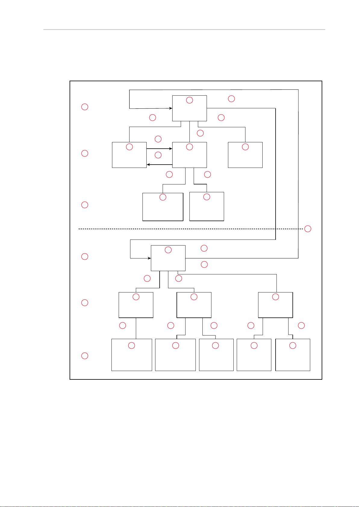
User Interface Flow Diagram
The following diagram shows the flow of the T20 pendant user interface. Please note the following:
l
The Menu button always returns you to the Home 1 screen. See the next section.
l
The Cancel button always takes you back one screen (up one level in the diagram).
Additionally, in the case of the Expanded Array screens, these continue to repeat, if
there are arrays within arrays. At each level, pressing the Cancel button will back up
exactly one level.
l
The software incorporates a button blocking feature, which ignores continued button
30 T20 Pendant User's Manual 10433-000 Rev. H
Page 31
Chapter 4: Operation
Home 1
Home 2
Position
Display
Locations
I/O
Frame
Tool
Maintenance
Info Error List
Expanded Array
(If the level above
was an array)
Tool Display
Location
Teaching
Page
Expanded Array
(If the level above
was an array)
Expanded Array
(If the level above
was an array)
F4 (Next >)
F4 (Next >)
F1 (Disp)
F2 (Loc)
F3 (I/O)
F1 (Frame) F2 (Tool)
F3 (Maint)
F2 (Expand)
F1 (Disp)
F2 (Loc)
F1 (Expand) F1 (Expand) F2 (Errors)F1 (Info)F1 (Disp)
F2 (Teach)
LEVEL 1
LEVEL 2
LEVEL 3
LEVEL 1
LEVEL 2
LEVEL 3
1
2
20
19
18
17
16
15
14
13
12
11
10
9
8
7
6
5
4
3
30
2928
27
26
25
24
23
2221
31 32
33
34 35 36 37 38
39
inputs while the pendant is processing the current input. This is most notable during
the Power On sequence, which may take a few seconds, during which time the pendant
will not respond. This prevents the pendant from suddenly executing a series of
queued-up inputs, if you have moved on to a different command screen.
Figure 4-5. User Interface Flow Diagram
10433-000 Rev. H T20 Pendant User's Manual 31
Page 32

4.4 User Interface Operation
Table 4-5. User Interface Flow Descriptions
Item Description Item Description Item Description
1 LEVEL 1 14 F2 (Expand) 27 Maintenance
2 Home 1 15
Expanded Array (If the level
28 F1 (Expand)
above was an array)
3 F4 (Next >) 16
4 F1 (Disp) 17
5 F2 (Loc) 18
6 F3 (I/O) 19
F2 (Teach)
Location Teaching Page
LEVEL 1
Home 2
29 F1 (Expand)
30 F1 (Disp)
31 F1 (Info)
32 F2 (Errors)
7 LEVEL 2 20 F4 (Next >) 33 LEVEL 3
8 Position
Display
21 F1 (Frame) 34 Expanded Array (If the level
above was an array)
9 F2 (Loc) 22 F2 (Tool) 35 Expanded Array (If the level
above was an array)
10 Locations 23 F3 (Maint) 36 Tool Display
11 F1 (Disp) 24 LEVEL 2 37 Info
12 I/O 25 Frame 38 Error List
13 LEVEL 3 26 Tool 39 Home 1 / Home 2 division
32 T20 Pendant User's Manual 10433-000 Rev. H
Page 33

Chapter 4: Operation
Displaying the Home Screens
Pressing the Menu button on the T20 pendant displays the Home 1 screen as shown below.
There are two Home screens. Use the Next > soft key to switch between them.
Figure 4-6. Home 1 Screen
The following table describes the soft keys shown on the Home 1 screen. The soft keys are used
for quick access to the different screens and functions on the T20 pendant.
Table 4-6. Home 1 ScreenDescription
Soft
Key
Description
Disp Accesses the current World or Joint position screens. It also allows you to open and
close the gripper.
Loc Accesses the available locations and associated commands (such as a pick or place),
Teach, JogTo, Align, and New functions.
I/O Accesses the Type and Toggle functions, which allow you to select the type of I/O,
and toggle the selected signal on or off.
Next>Access the Home 2 screen, which displays additional soft keys.
10433-000 Rev. H T20 Pendant User's Manual 33
Page 34

4.5 Using Jog Mode
The following table describes the soft keys shown on the Home 2 screen.
Soft
Key
Frame Allows displaying available frames and selecting a frame for movement.
Tool Allows displaying available tools and displaying and setting the current tool.
Maint Accesses the System Maintenance screen, for setting screen saver, initial speed,
Smart Locations, approach distance, pendant messages, system information, error
functions, and firmware updates on the pendant.
Next> Returns to the Home 1 screen.
4.5 Using Jog Mode
Jog Mode and the jog control buttons allow you to position the connected or selected robot. The
following jog modes are available in the following order: COMP (computer), Joint, World, Tool,
and Free. When high power is enabled and the robot is calibrated, press Jog Mode to step
through these modes in sequential order. The selected mode is displayed in the Jog Mode indicator. When any of these modes other than COMP is active, the Jog LED lights. You can use the
jog control feature while any of the software screens are displayed.
Figure 4-7. Home 2 Screen
Table 4-7. Home 2 Screen Description
Description
34 T20 Pendant User's Manual 10433-000 Rev. H
Page 35

Chapter 4: Operation
1
2
4
3
1
2
3
4
COMP Mode
In COMP mode, an executing program or the system terminal has control of the robot. To
select COMP mode, press the Jog Mode button until COMP is displayed in the Jog Mode indicator.
NOTE: You cannot use jog control to move a robot while in COMP mode.
Joint Mode
When Joint mode is selected, movement is about the axis of the specified joint. The following
figure shows a Cobra robot with three rotational joints (Joints 1, 2, and 4) and one translational
joint (Joint 3). Positive rotation of Joints 1 and 2 is counterclockwise as viewed from above. Positive rotation of Joint 4 is clockwise as viewed from above. Positive movement of Joint 3 is
downward.
Different robots or motion devices will have different joint numbers assigned to their joints.
When you first move an unfamiliar robot using Joint mode, set the jog speed to 10 or lower,
put the robot in a safe area, and carefully move the robot using the different joint numbers to
verify how the pendant moves the robot. See the documentation for the motion devices you are
using for details on their joint assignments.
Figure 4-8. Joint Mode - Pendant Joint / Axis Control Buttons (Four-Axis Scara Robot Shown)
Table 4-8. Joint Mode Axis Descriptions
Item Description
1 Joint 1
2 Joint 2
3 Joint 3
4 Joint 4
10433-000 Rev. H T20 Pendant User's Manual 35
Page 36

4.5 Using Jog Mode
1
2
4
3
4
3
2
1
To position the robot while in Joint mode:
1.
Press the Jog Mode button until Joint is displayed in the Jog Mode indicator.
2.
Press and hold the '+' button to move the robot joint in the positive direction; press and
hold the '–' button to move the robot joint in the negative direction.
World Mode
When World mode is selected, movement in the X, Y, or Z direction is parallel to an axis of the
World coordinate system.
Figure 4-9. World Mode - Pendant Joint / Axis ControlButtons (Four-Axis Scara Robot Shown)
Table 4-9. World Mode AxisDescriptions
Item Description
1 +X (X Direction)
2 +Y(YDirection)
3 +Z(ZDirection)
4 +RZ, CCW (RZRotation)
To position the robot while in World mode:
1.
Press the Jog Mode button until World is displayed in the Jog Mode indicator.
2.
Press and hold the '+' button to move the robot tool flange in the positive direction;
36 T20 Pendant User's Manual 10433-000 Rev. H
Page 37

Chapter 4: Operation
1
2
4
3
1
2
3
4
press and hold the '–' button to move the flange in the negative direction
Tool Mode
When Tool mode is selected, movement in the X, Y, or Z direction is along an axis of the Tool
coordinate system. The Tool coordinate system is centered at the robot tool flange with the Zaxis pointing away from the flange. On most robots, the positive X-axis is aligned with the center of the tool flange keyway.
Figure 4-10. Tool Mode - Pendant Joint / Axis ControlButtons (Four-Axis Scara Robot Shown)
Table 4-10. Tool Mode Axis Descriptions
Item Description
1 +X (XDirection)
2 +Y (YDirection)
3 +Z (Z Direction)
4 +RZ(Rotation About Tool ZAxis)
NOTE: The previous drawing assumes that the tool transformation is set to null
(all values are 0). If a tool transformation is in effect, the tool coordinate system
will be offset and rotated by the value of the tool transformation. Any motion in
10433-000 Rev. H T20 Pendant User's Manual 37
Page 38

4.6 Speed Control
!
Tool mode will now be relative to the offset coordinate system, and not the center
of the tool flange.
To position the robot while in Tool mode:
1.
Press the Jog Mode button until Tool is displayed in the Jog Mode indicator.
2.
Press and hold the '+' button to move the robot tool flange in the positive direction;
press and hold the '–' button to move the flange in the negative direction. In a four-axis
robot, positive rotation of the gripper (RZ) is clockwise as viewed from above.
Free Mode
When Free mode is selected, the motor torque will be zeroed and the brake (if any) for the selected joint will be released. You can make multiple selections with the Joint/Axis control buttons
to release as many joints as required.
To select Free mode, press the Jog Mode button until Free is displayed in the Jog Mode indicator. As soon as another jog control mode is selected, all joints are returned to servo control
and will not move freely.
On some robots, Free mode is disabled for some of the joints.
The joint assignments in Free mode are the same as the joint assignments in Joint mode. See
the preceding figure.
WARNING: When a joint is selected using the Joint/Axis control buttons
while in Free mode, the corresponding joint is released and moves freely (in
some mechanisms, multiple joints may be released). In many cases, the weight
on the joint will be sufficient to move the joint and cause equipment damage or
injury to personnel in the workspace.
4.6 Speed Control
You can change the robot speed using the Speed +, Speed -, and Slow buttons. The selected
speed will be applied when you use the jog controls to move the robot.
While Slow speed is active, a red horizontal line and hash marks are displayed in the part of
the speed indicator above 20%, showing that you cannot increase the speed beyond 20%. See
the following figure.
38 T20 Pendant User's Manual 10433-000 Rev. H
Page 39

Chapter 4: Operation
Figure 4-11. Speed Indicator (Slow Mode)
l
In COMP mode, the speed control and speed indicator pertain to monitor speed.
l
In other modes, the speed control and speed indicator pertain to jog speed.
Jog speed is the percentage of the speed in manual mode, which is settable in the ACE
or Sysmac Studio software with the manual control maximum speed parameter.
4.7 Position Display
To display coordinate information about the robot's current position, press Disp. The coordinates for the robot's current location are displayed.
Figure 4-12. Position Display, World Coordinates
10433-000 Rev. H T20 Pendant User's Manual 39
Page 40

4.8 Smart Locations
l
Press Disp to toggle the display between the World and Joint coordinate systems.
l
Press Grip to open and close a gripper installed on the tool flange.
l
Press Loc to display the Available Locations screen.
4.8 Smart Locations
A pendant option, called Smart Locations (available on the System Maintenance screen),
shows all locations that have the string “tool” in them on the Available Tools screen, all locations that have the string “frame” in them in the Available Frames screen, and all locations
that don’t match “tool” or “frame” in the Available Locations screen. If the option is disabled,
all locations are shown on all three screens. See the examples in the following table.
Figure 4-13. Position Display, Joint Coordinates
40 T20 Pendant User's Manual 10433-000 Rev. H
Page 41

Chapter 4: Operation
Table 4-11. Smart Locations Enabled versus Disabled
Smart Locations Enabled Smart Locations Disabled
4.9 Available Frames
The Available Frames screen is used to set the jog mode relative to the selected frame. This is
the only way to enter the Frame jog mode. When this is done, the jog controls will move the
robot in relation to the selected frame, rather than the World coordinates (robot base).
10433-000 Rev. H T20 Pendant User's Manual 41
Page 42

4.9 Available Frames
Figure 4-14. Available Frames Screen
NOTE: Once you use Jog Mode to cycle to another jog mode, you cannot return
to Frame mode without going back to this screen.
Enable Frame-Based Jogging
1.
From the Home 2 screen, press the Frame soft key. The Available Frames screen opens.
2.
Use the arrow buttons to select the desired frame.
3.
Press the Jog soft key to enable jogging based on the selected frame.
The system will now jog in Frame mode (this is displayed as JOG REL: <FrameName>).
A Note about Frame-mode Jogging
When locations are taught while in frame-jogging mode (see the previous section), they are
taught relative to the selected frame. When locations are jogged to while in frame-jogging
mode, they are jogged relative to the currently-selected frame.
This feature was designed to allow you to teach, and then jog to locations relative to another
frame, such as a palette, all from the pendant. However, it does provide the opportunity for
confusion: The most likely user error here would be to teach a position in “JOG REL: XXX”,
then change jog modes, and later try to jog to the new position while in world mode – this
would produce either no movement (if the position is unreachable) or, possibly, movement to
an arbitrary location, because the relative frame is no longer involved.
42 T20 Pendant User's Manual 10433-000 Rev. H
Page 43

4.10 Available Tools
The Available Tools screen provides the ability to view and set a tool transformation (or offset).
Chapter 4: Operation
While on this screen, you can:
l
Press the Disp soft key to display the value of the selected tool transformation (you can
select CURRENT TOOL to display the current tool transformation). After you display a
tool (other than current tool), pressing the Disp soft key will then toggle between that
tool and the current tool, which allows you to see if it is the selected tool.
l
Set a tool—select the desired tool from the list and press OK to set it.
l
Press the Null soft key to set the current tool transformation (or offset) to null tool (no
tool offset frame in use).
4.11 Location Teaching
Press the Loc soft key from the pendant Home 1 screen to display the Available Locations
screen shown in the following figure.
Figure 4-15. Available Tools Screen
10433-000 Rev. H T20 Pendant User's Manual 43
Page 44

4.11 Location Teaching
Figure 4-16. Available Locations Screen 1
Figure 4-17. Available Locations Screen 2
The following table describes the soft keys shown on the Available Locations screens.
44 T20 Pendant User's Manual 10433-000 Rev. H
Page 45

Table 4-12. Available Locations Soft Key Descriptions
Chapter 4: Operation
Soft
Key
Description
Disp Shows the current position of the robot.
Teach Teaches the current position to the selected location.
New Creates a new location named pendant.loc[X] where X is the first available value
(1,2,3...).
JogTo Press and hold to move (jog) the robot to the selected position.
Appro Press to bring the robot to the approach position for the selected location. The
approach position is the location less 'A' mm along the Z-axis of the tool transformation (or offset), where 'A' is the approach distance set on the System Maintenance screen.
Align Aligns the robot tool Z-axis with the nearest world axis.
Next> Goes to the next Available Locations screen.
To teach a location:
1.
From the Available Locations screen, press the arrow buttons to select the desired location from the list of locations.
2.
Press Teach. The Teach screen opens for the selected location.
3.
Use the jog controls to position the robot at the desired location.
4.
When the robot is at the desired location, press OK to teach the position.
10433-000 Rev. H T20 Pendant User's Manual 45
Page 46

4.11 Location Teaching
Figure 4-18. Teach Screen
To select an array:
1.
From the Available Locations screen, press the up/down arrow buttons to select the
desired array, and then press Expand. The valid members of the selected array are displayed.
2.
Press the up/down arrow buttons to select the desired location.
Press Cancel to return to the previous screen.
Adding Approach Distance
You can specify an approach distance through the System Maintenance screen. For details, see
Setting the Approach Distance on page 53.
After the approach distance is set, you can use the Appro soft key to bring the robot to the
approach position for the selected location. The approach position is the location less 'A' mm
along the Z-axis of the tool transformation (or offset), where 'A' is the approach distance set on
the System Maintenance screen.
Using Jog To
Use Jog To to move the robot to a selected location (stored in memory).
To jog the robot to a location:
1.
Press Loc from the Home 1 screen to display the Available Locations screen.
2.
Press the arrow buttons to select the desired location.
3.
Press and hold Jog To until the robot is at the desired location. Release the button.
46 T20 Pendant User's Manual 10433-000 Rev. H
Page 47

NOTE: The predefined JOINTZERO location, sets the robot to #PPOINT
(0,0,0,0,0,0).
Align
Align works with Viper robots. While the Available Locations screen is displayed, you can
select a location and then press the Align soft key to align the nearest axis of the tool transformation (or offset) to the Z axis.
NOTE: Align is only available for six-axis robots, like the Viper robots.
NOTE: Other than the green Joint/Axis control buttons, the Jog To and Align
functions are the only functions available for moving the robot.
4.12 I/O Signals
NOTE: The T20 pendant does not support network I/O over EtherCAT. These
I/O signals are exchanged between the T20 and the robot that it is attached to.
Press the I/O soft key on Home 1 screen to display the screens used to control I/O signals. The
I/O Signals feature allows users to toggle outputs ON (active, high) and OFF (inactive, low).
Round icons represent input signals; square icons represent output signals. The available signal types are: digital output, digital input, soft, and robot.
Chapter 4: Operation
Figure 4-19. Digital Input Screen
10433-000 Rev. H T20 Pendant User's Manual 47
Page 48

4.12 I/O Signals
After pressing the I/O soft key, perform the following steps to control I/O signals.
1.
Press the Type soft key to cycle through the available signal types until the desired signal type is displayed. The current signal type and the selected signal number are displayed at the top of the screen.
2.
Press the arrow buttons to select the desired signal. The selected signal is identified by a
red outline.
If more than one row of signals is available, press the up/down arrow buttons to scroll
through the rows of signals. If more than one screen full of signals is displayed, press
PgUp/PgDn soft keys to scroll through the screens.
3.
For output signals, press the Toggle soft key to turn the selected signal ON or OFF.
Figure 4-20. Digital Output Screen
NOTE: In the preceding screen, the PgUp and PgDn soft keys are grey, rather
than blue, because there is only one screen available for digital outputs, so page
up and page down are not available.
48 T20 Pendant User's Manual 10433-000 Rev. H
Page 49

4.13 Displaying and Clearing Errors
When errors occur, the ERR LED lights and a screen describing the error is displayed. Press
OK or Cancel to clear the error information.
While the error screen is displayed, the Menu button, arrow buttons, and soft keys are disabled. Even though the soft keys remain blue, they are not active in this state.
Chapter 4: Operation
Figure 4-21. Error Screen
In order for these errors to be displayed, the Pendant Msgs must be Enabled, from the System
Maintenance screen.
NOTE: If the pendant ever loses contact with the controller, the pendant will display the Connection Lost screen. From this screen, you will be prompted to reconnect with the controller. This message is not affected by the Pendant Msgs
setting.
You can display a list of errors that have occurred since the pendant was last powered up. For
details, see Displaying Recent Errors on page 55.
10433-000 Rev. H T20 Pendant User's Manual 49
Page 50

Page 51

Chapter 5: Maintenance
This chapter describes how to set the screen saver, set default values for initial speed and
approach distance, enable smart locations and pendant messages, update the pendant's firmware, troubleshoot problems, and maintain the pendant.
5.1 The System Maintenance Screen
The System Maintenance screen is used to set various pendant options, obtain information on
the system, and view the error log.
Figure 5-1. System Maintenance Screen
The following table describes the options shown on the System Maintenance screen.
Table 5-1. System MaintenanceOption Descriptions
Option Description
Screen
Saver
Initial
Speed
10433-000 Rev. H T20 Pendant User's Manual 51
Sets the screen-idle time (Thirty Seconds, One Minute, Two Minutes, Five
Minutes, Ten Minutes, Twenty Minutes, One Hour) before the screen saver is
activated. For details, see Setting the Screen Saver on page 52.
Sets the default speed used when the system starts up (Slow, Normal). For
details, see Setting the Initial Speed on page 53.
Page 52

5.2 Setting the Screen Saver
Option Description
Smart
Locations
Approach
Dist
Pendant
Msgs
Enables/disables the Smart Locations feature, which organizes the locations by
type. For details, see Enabling Smart Locations on page 53.
Sets the approach distance (1 mm to 200 mm). For details, see Setting the
Approach Distance on page 53.
Enables/disables whether errors are displayed. If disabled, errors are not reported
to the pendant.
The following table describes the soft keys shown on the System Maintenance screen.
Table 5-2. System Maintenance Soft Key Descriptions
Soft
Key
Info Accesses a screen that displays the system information from the controller. For
details, see Displaying System Information on page 54.
Errors Accesses the error log. For details, see Displaying Recent Errors on page 55.
Update Updates the pendant firmware. For details, see Displaying System Information on
page 54.
5.2 Setting the Screen Saver
Description
You can specify the length of time without activity before the screen saver is activated.
To set the screen saver idle time:
1.
From the Home 1 screen, press Next > to display the Home 2 screen.
2.
Press Maint. The System Maintenance screen opens.
3.
If necessary, press the up/down arrow buttons to select the Screen Saver field. Press OK.
4.
Press the up/down arrow buttons to select the length of time before the screen saver is
activated.
The options available are:
l
Thirty Seconds
l
One Minutes
l
Two Minutes
l
Five Minutes
l
Ten Minutes
l
Twenty Minutes
l
One Hour
5.
Press OK to accept the change. Press Cancel to revert to the previous setting.
52 T20 Pendant User's Manual 10433-000 Rev. H
Page 53

5.3 Setting the Initial Speed
You can specify Normal or Slow as the default speed setting when the system starts up. The
pendant comes with Normal as the default setting.
To select the initial speed:
1.
From the Home 1 screen, press Next > to display the Home 2 screen.
2.
Press Maint. The System Maintenance screen opens.
3.
Press the up/down arrow buttons to select the Initial Speed field. Press OK.
4.
Press the up/down arrow buttons to select either Normal or Slow for the initial speed.
5.
Press OK to accept the change. Press Cancel to revert to the previous setting.
5.4 Enabling Smart Locations
The Smart Locations option allows you to view tool, frame, and general locations on separate
pages. For more details on this option, see Smart Locations on page 40.
To enable the Smart Locations option:
1.
From the Home 1 screen, press Next > to display the Home 2 screen.
Chapter 5: Maintenance
2.
Press Maint. The System Maintenance screen opens.
3.
Press the up/down arrow buttons to select the Smart Locations option. Press OK.
4.
Press the up/down arrow buttons to select Enabled or Disabled.
5.
Press OK to accept the change. Press Cancel to revert to the previous setting.
5.5 Setting the Approach Distance
You can specify the approach distance, which is used by the robot when moving to a location.
For details on teaching locations, see Location Teaching on page 43.
To select the approach distance:
1.
From the Home 1 screen, press Next > to display the Home 2 screen.
2.
Press Maint. The System Maintenance screen opens.
3.
Press the up/down arrow buttons to select the Approach field. Press OK.
4.
Press the up/down arrow buttons to select a value from 1 mm to 200 mm.
5.
Press OK to accept the change. Press Cancel to revert to the previous setting.
10433-000 Rev. H T20 Pendant User's Manual 53
Page 54

5.6 Enabling Pendant Messages
5.6 Enabling Pendant Messages
You can disable all error messages except the Connection Lost screen, which is displayed if the
T20 pendant ever loses connection to the SmartController EX motion controller.
To enable the display of error messages on the pendant:
1.
From the Home 1 screen, press Next > to display the Home 2 screen.
2.
Press Maint. The System Maintenance screen opens.
3.
Press the up/down arrow buttons to select the Pendant Msgs option. Press OK.
4.
Press the up/down arrow buttons to select Enabled or Disabled.
5.
Press OK to accept the change. Press Cancel to revert to the previous setting.
5.7 Displaying System Information
The System Information screen displays identity information about components of the system,
as returned by the ID and NETmonitor commands.
The screen displays the IP address of the connected controller. The controller type and OP / SV
switch position have the following affect on the IP address displayed.
Controller Type OP/SV Switch Position IPAddress Displayed
SmartController EX
N/A
eAIB or eMB eAIB or eMB
OP NJ-series Robot Integrated
iCS-ECAT or eCS-ECAT
SV iCS-ECAT or eCS-ECAT
SmartController EX
CPU unit
To access the System Information screen:
1.
From the Home 1 screen, press Next > to display the Home 2 screen.
2.
Press Maint. The System Maintenance screen opens.
3.
From the System Maintenance screen, press the Info soft key. The following screen
opens.
54 T20 Pendant User's Manual 10433-000 Rev. H
Page 55

Chapter 5: Maintenance
Figure 5-2. Sample System Information Screen
5.8 Displaying Recent Errors
You can display a list of errors that have occurred since the pendant was last powered up.
To display recent errors:
1.
From the Home 1 screen, press Next > to display the Home 2 screen.
2.
Press Maint. The System Maintenance screen opens.
3.
Press the Errors soft key. The Recent Errors screen opens.
4.
If necessary, press the up/down arrow buttons to select the error of interest.
5.
Press the Detail soft key to display details about the selected error.
10433-000 Rev. H T20 Pendant User's Manual 55
Page 56

5.9 Updating the Pendant Firmware
Figure 5-3. Recent Errors and Detail Screens
6.
Press List to return to the Recent Errors screen.
5.9 Updating the Pendant Firmware
To update the pendant firmware:
56 T20 Pendant User's Manual 10433-000 Rev. H
Page 57
Chapter 5: Maintenance
1.
Turn OFF power to the SmartController EX motion controller or disconnect the T20
pendant from the controller (see Installation on page 18).
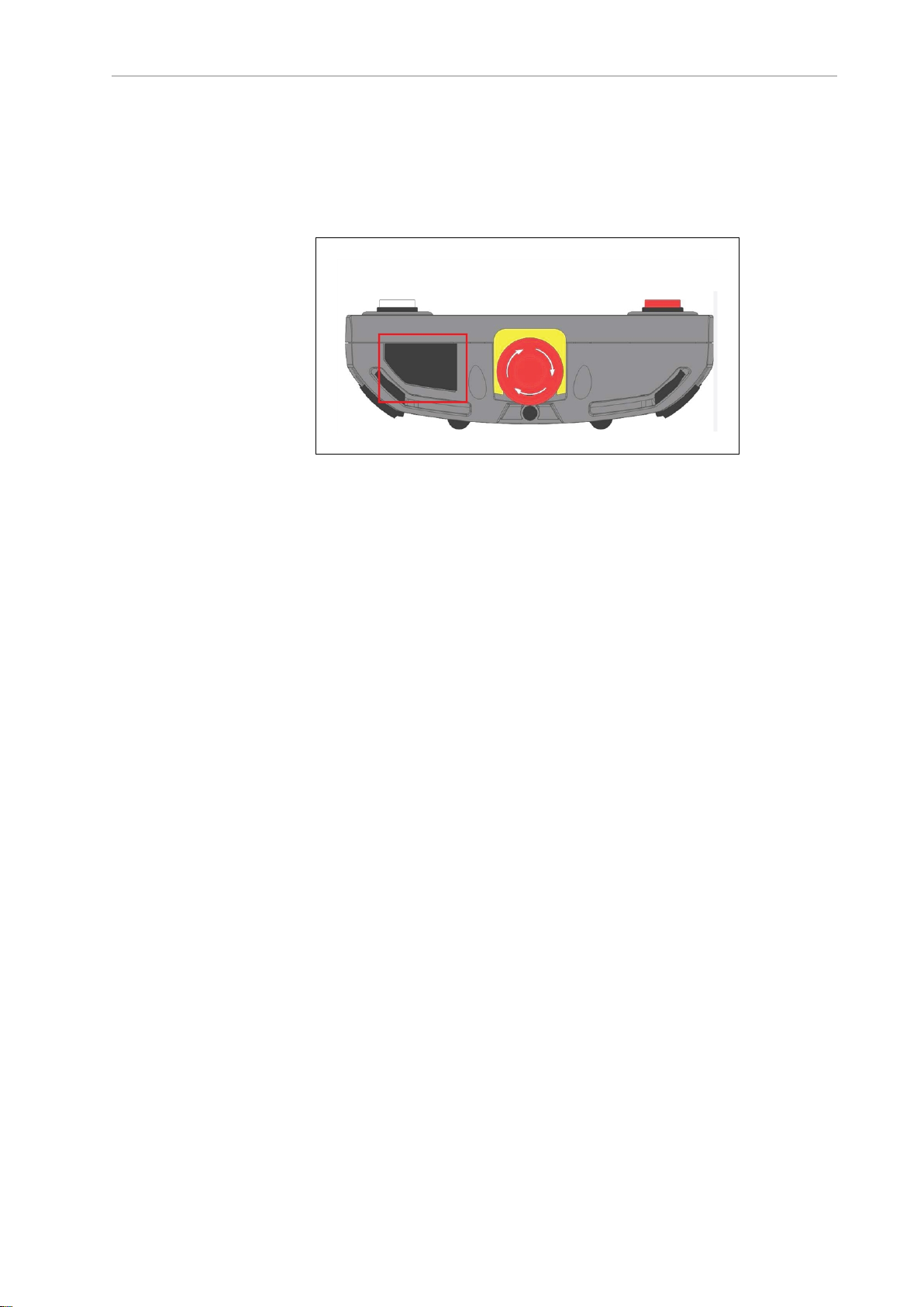
2.
Insert a Micro SD card containing the firmware update files and
"T20UpdatePackage.dat" into the pendant. Make sure the files are located under the following path and folder name: "\T20Update".
Figure 5-4. Location for Inserting Micro SD Card in Pendant
3.
Reapply power to the controller, or reconnect the T20 pendant to the controller, depending on how you removed power.
4.
After a reboot, on the Home 1 screen, press Next > to display the Home 2 screen.
5.
Press Maint. The System Maintenance screen opens.
6.
Press the Update soft key.
7.
Press OK. A screen displaying status messages about the update will be displayed. The
messages should indicate that the system was able to detect the firmware update and
that the firmware update was successfully verified.
8. Press OK. The firmware will be copied to the pendant.
9.
After the update has completed, the pendant reboots automatically.
If you encounter any problems while updating the firmware, check the following:
l
Make sure the Micro SD card is fully inserted in the pendant and that you reboot the
pendant after inserting the Micro SD card.
l
Make sure the firmware update files are stored in a folder named "T20Update" on the
Micro SD card.
l
The update package performs a checksum test to verify the integrity of the contents of
the update files. If any of the files are corrupted, the update package will fail to verify
the contents. If this error occurs, obtain new update files from your local OMRON representative.
NOTE: In the event a firmware update fails, you can operate the pendant using
the factory-installed firmware, which is always present on the pendant.
10433-000 Rev. H T20 Pendant User's Manual 57
Page 58

5.10 Loss of Communication
!
5.10 Loss of Communication
If the T20 pendant ever loses communication with the connected controller for any reason (e.g.
controller reboot), a Communication Lost screen will be displayed. From this screen, pressing
OK will tell the pendant to try to restablish communication with the controller.
If the reconnection fails, use the ACE or Sysmac Studio software to verify that the controller's
monitor window is responsive. If this state persists, contact your local OMRON representative
for assistance.
5.11 Cleaning
To clean the T20 pendant, use a soft cloth dampened with a small amount of water or a mild
cleaning agent.
CAUTION: Never clean the T20 pendant display screen or other surfaces with
solvents, abrasive cleaners, or scrubbing sponges.
5.12 Periodic Maintenance
Periodically check the protective covers of the T20 pendant to ensure that all housing screws
are firmly tightened, and that there is no damage to the cable entry area, sealing plug, or cable
strain-relief.
Figure 5-5. Connection Lost Screen
58 T20 Pendant User's Manual 10433-000 Rev. H
Page 59

Chapter 6: Technical Specifications
6.1 Dimension Drawings
Figure 6-1. T20 Pendant Dimensions (Units in mm)
6.2 Pendant Specifications
Table 6-1. T20 Pendant Specifications
Description Specification
Physical
Length 224 mm
Width 162 mm
Depth 45 mm
Weight (w/o connector) 480 g
Pendant Cable Length 10 m
10433-000 Rev. H T20 Pendant User's Manual 59
Page 60

6.2 Pendant Specifications
Description Specification
Adapter Cable Length 3 m
Safety Controls 1 Emergency Stop (E-Stop) switch
Construction/Rating
Ingress Protection IP65
Shock Resistance (operating) 25 g / 11 ms (IEC 60068-2-27)
Display Type High-resolution color OLED display
Construction Steel panel housing, blue zinc-coated
Flammability Class UL 94-V0
Environmental
Operating Temperature 0 to 45°C
1 3-position Enable switch
1 Auto/Manual key switch
surface. Withstands grease, oil, alcohol, and lubricants.
Storage Temperature -25 to 60°C
Relative Humidity (non-condensing) 5% to 95%
60 T20 Pendant User's Manual 10433-000 Rev. H
Page 61

Page 62

OMRON Corporation Industrial Automation Company
Kyoto, JAPAN
Regional Headquarters
OMRON EUROPE B.V.
Wegalaan 67-69, 2132 JD Hoofddorp
The Netherlands
Tel: (31)2356-81-300/Fax: (31)2356-81-388
OMRON ASIA PACIFIC PTE. LTD.
No. 438A Alexandra Road # 05-05/08 (Lobby 2),
Alexandra Technopark,
Singapore 119967
Tel: (65) 6835-3011/Fax: (65) 6835-2711
Contact: www.ia.omron.com
OMRON ELECTRONICS LLC
2895 Greenspoint Parkway, Suite 200 Hoffman Estates,
IL 60169 U.S.A.
Tel: (1) 847-843-7900/Fax: (1) 847-843-7787
OMRON ROBOTICS AND SAFETY TECHNOLOGIES, INC.
4225 Hacienda Drive, Pleasanton, CA 94588 U.S.A
Tel: (1) 925-245-3400/Fax: (1) 925-960-0590
OMRON (CHINA) CO., LTD.
Room 2211, Bank of China Tower, 200 Yin Cheng Zhong Road,
PuDong New Area, Shanghai, 200120, China
Tel: (86) 21-5037-2222/Fax: (86) 21-5037-2200
Authorized Distributor:
© OMRON Corporation 2016-2020
All Rights Reserved. In the interest of product
improvement, specifications are subject to change
without notice.
Cat. No. I601-E-04
0820
10433-000 H
 Loading...