

Page 1
Automation Software
Sysmac Studio
Version 1
Drive Functions Operation Manual
SYSMAC-SE2
I589-E1-06
Page 2

NOTE
All rights reserved. No part of this publication may be reproduced, stored in a retrieval system, or transmitted, in
any form, or by any means, mechanical, electronic, photocopying, recording, or otherwise, without the prior
written permission of OMRON.
No patent liability is assumed with respect to the use of the information contained herein. Moreover, because
OMRON is constantly striving to improve its high-quality products, the information contained in this manual is
subject to change without notice. Every precaution has been taken in the preparation of this manual. Nevertheless, OMRON assumes no responsibility for errors or omissions. Neither is any liability assumed for damages
resulting from the use of the information contained in this publication.
Trademarks
• Sysmac and SYSMAC are trademarks or registered trademarks of OMRON Corporation in Japan and other
countries for OMRON factory automation products.
• Microsoft, Windows, Windows Vista, Excel, and Visual Basic are either registered trademarks or trademarks of
Microsoft Corporation in the United States and other countries.
• EtherCAT® is registered trademark and patented technology, licensed by Beckhoff Automation GmbH, Germany.
• ODVA, CIP, CompoNet, DeviceNet, and EtherNet/IP are trademarks of ODVA.
• The SD and SDHC logos are trademarks of SD-3C, LLC.
• NVIDIA, the NVIDIA logo, GeForce, and the GeForce logo are the trademarks or registered trademarks of NVIDIA
Corporation in the USA and other countries.
• ATITM, RadeonTM is a trademark of Advanced Micro Devices, Inc..
• Celeron, Intel and Intel Core are trademarks of Intel Corporation in the U.S. and / or other countries.
Other company names and product names in this document are the trademarks or registered trademarks of their
respective companies.
Copyrights
Microsoft product screen shots reprinted with permission from Microsoft Corporation.
Page 3

Introduction
Thank you for purchasing Sysmac Studio Automation Software.
Sysmac Studio allows you to use a computer to program and set up Sysmac devices.
Introduction
This manual describes the operating procedures of Sysmac
Use this manual together with the Sysmac
user’s manuals of the devices that you use.
Intended Audience
This manual is intended for the following personnel, who must also have knowledge of electrical systems (an electrical engineer or the equivalent).
• Personnel in charge of introducing FA systems.
• Personnel in charge of designing FA systems.
• Personnel in charge of installing and maintaining FA sy
• Personnel in charge of managing FA systems and facilities.
For
programming, this manual is intended for pers
specifications in international standard IEC 61131-3 or Japanese standard JIS B 3503.
Notice
This manual contains information that is necessary to use the Sysmac Studio. Please read and understand this manual before using the Sysmac S
available for reference during operation.
Studio mainly for drive functions.
Studio Version 1 Operation Manual (Cat. No. W504) and the
stems.
onnel who understand the programming language
tudio. Keep this manual in a safe place where it will be
Sysmac Studio Drive Functions Operation Manual (I589)
1
Page 4
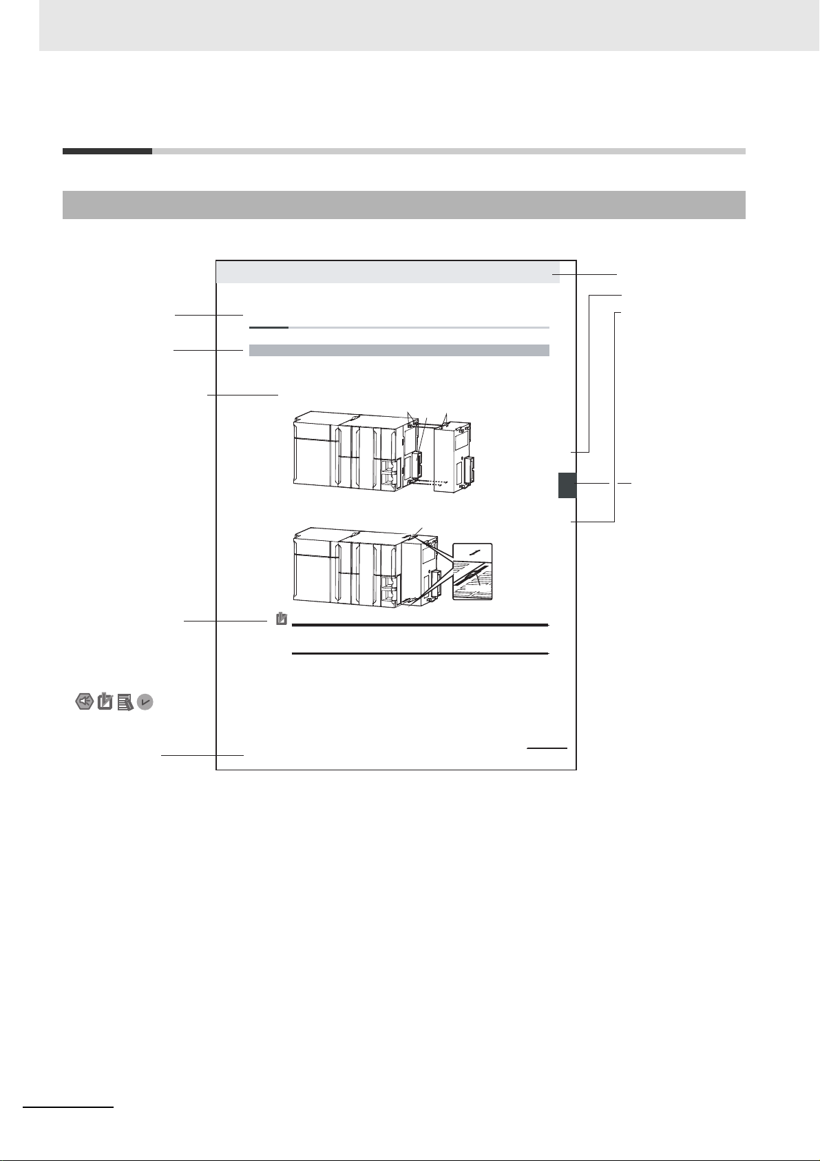
Manual Structure
4-9
4 Installation and Wiring
NJ-series CPU Unit Hardware User’s Manual (W500)
stinU gnitnuoM 3-4
4
stnenopmoC rellortnoC gnitcennoC 1-3-4
4-3 Mounting Units
The Units that make up an NJ-series Controller can be connected simply by pressing the Units together
and locki ng the slide rs by moving the m toward the back of the U nits. The End Cover is connect ed in the
same way to the Unit on the far right side of the Controller.
1 Join the Units so that the connectors fit exactly.
2 The yellow sliders at the top and bottom of each Unit lock the Units together. Move the sliders
toward the back of the Units as shown below until they click into place.
Precautions for Correct UsePrecautions for Correct Use
4-3-1 Connecting Controller Components
Connector
Hook
Hook holes
Slider
Lock
Release
Move the sliders toward the back
until they lock into place.
Level 1 heading
Level 2 heading
Level 3 heading
Level 2 heading
A step in a procedure
Manual name
Special information
Level 3 heading
Page tab
Gives the current
headings.
Indicates a procedure.
Icons indicate
precautions, additional
information, or reference
information.
Gives the number
of the main section.
The sliders on the tops and bottoms of the Power Supply Unit, CPU Unit, I/O Units, Special I/O
Units, and CPU Bus Units must be completely locked (until they click into place) after connecting
the adjacent Unit connectors.
Manual Structure
Page Structure
The following page structure is used in this manual.
This illustration is provided only as a sample.
It may not literally appear in this manual.
2
Sysmac Studio Drive Functions Operation Manual (I589)
Page 5

Special Information
Manual Structure
Special information in this manual is classified as follows:
Precautions for Safe Use
Precautions on what to do and what not to do to ensure safe usage of the product.
Precautions for Correct Use
Precautions on what to do and what not to do to ensure proper operation and performance.
Additional Information
Additional information to read as required.
This information is provided to incre
Version Information
Information on differences in specifications and functionality for CPU Units
and for different versions of the Sysmac Studio is given.
Note References are provided to more detailed or related information.
Precaution on Terminology
• In this manual, “download” refers to transferring data from the Sysmac Studio to the physical Controller and “upload” refers to transferring data from the ph
For the Sysmac Studio, synchronization is used to both upload and download data. Here, “synchronize” means to automatically compare the data for th
in the physical Controller and transfer the data in the direction that is specified by the user.
• The Sysmac Studio supports the NJ/NX/NY-series Contro
specified, the operating procedures and screen captures used in the manual are examples for the
NJ-series Controllers.
a
se understanding or make operation easier.
with different unit versions
ysical Controller to the Sysmac Studio.
e Sysmac Studio on the computer with the data
llers. Unless another Controller series is
Terminology
For descriptions of the Controller terms that are used in this manual, refer to information on terminology
in the manuals that are listed in Related Manuals on
page 19.
Sysmac Studio Drive Functions Operation Manual (I589)
3
Page 6

Manual Structure
4
Sysmac Studio Drive Functions Operation Manual (I589)
Page 7

1
2
3
4
5
1
2
3
4
5
Sysmac Studio Drive Functions
Overview of the Operations
Basic Servo Drive Operations
Applied Servo Drive Operations
Other Servo Drive Operations
Sections in this Manual
Sections in this Manual
Sysmac Studio Drive Functions Operation Manual (I589)
5
Page 8

CONTENTS
CONTENTS
Introduction ..............................................................................................................1
Intended Audience....................................................................................................................................... 1
Notice............................................................................................................................
Manual Structure ......................................................................................................2
Special Information...................................................................................................................................... 3
Sections in this Manual ...........................................................................................5
Terms and Conditions Agreement.......................................................................... 8
Safety Precautions ...................................................................................................9
Definition of Precautionary Information........................................................................................................ 9
Symbols..............................................................................................................................
Precaution for Safe Use......................................................................................... 12
............................... 1
......................... 9
Precautions for Correct Use.................................................................................. 14
Regulations and Standards...................................................................................15
Software Licenses and Copyrights ............................................................................................................ 15
Versions ..................................................................................................................16
Unit Versions ............................................................................................................................................. 16
Checking Versions..................................................................................................................................... 16
Unit Versions and Sysmac Studio Versions .............................................................................................. 18
Related Manuals .....................................................................................................19
Revision History .....................................................................................................20
Section 1 Sysmac Studio Drive Functions
1-1 Sysmac Studio Drive Functions........................................................................................... 1-2
1-2 System Configuration ...........................................................................................................
1-2-1 Connection to Drive.....................................................................................................................1-3
1-2-2 Applicable Drives and Communications Types..............
Section 2 Overview of the Operations
1-3
.............................................................1-5
2-1 Basic Operation Flow............................................................................................................ 2-2
2-1-1 1S Series.....................................................................................................................................2-2
2-1-2 G5 Series .......................................................................................................................
2-2 Installation and Uninstallation ............................................................................................. 2-8
2-3 Creating a Project................................................................................................................
2-3-1 Using a Drive with an OMRON NJ/NX/NY-series Controller.......................................................2-9
2-3-2 Using a Drive Independently.....................................................................................................
2-4 Areas of the Application Window ...................................................................................... 2-12
2-4-1 Overview of the Application Window .........................................................................................2-12
2-4-2 Multiview Explorer............................................................................................................
2-4-3 Toolbar........................................................................................................................
2-5 Project Data.......................................................................................................................... 2-17
6
Sysmac Studio Drive Functions Operation Manual (I589)
.............2-6
.. 2-9
2-10
......... 2-13
..............2-16
Page 9

2-5-1 Project Management................................................................................................................. 2-17
2-5-2 Project Data..................................................................................................................
2-5-3 Import and Export ..................................................................................................................... 2-19
2-6 Functions, Use Cases, and Operation Procedures .......................................................... 2-20
2-6-1 1S Series .................................................................................................................................. 2-20
2-6-2 G5 Series.................................................................................................................................. 2-22
2-6-3 Function and Operation Procedures for Each Drive ................................................................. 2-23
2-7 Online Connection Procedure............................................................................................ 2-24
Section 3 Basic Servo Drive Operations
3-1 Displaying and Editing Parameters ..................................................................................... 3-2
3-1-1 Displaying and Editing Drive Parameters ................................................................................... 3-2
3-1-2 Displaying and Editing Multi-drive Parameters (Drive Setting Ta
3-2 Auto Tuning ......................................................................................................................... 3-11
3-2-1 Auto Tuning for 1S Series......................................................................................................... 3-11
3-2-2 Auto Tuning for G5 Series .....................................................................................................
3-3 Test Run ............................................................................................................................... 3-18
3-4 Status Monitor ..................................................................................................................
3-5 Troubleshooting ..................................................................................................................
CONTENTS
............ 2-18
ble) ......................................... 3-9
... 3-12
... 3-22
3-23
3-6 Data Tracing......................................................................................................................
3-7 Motors and Encoders..........................................................................................................3-
3-7-1 Motor Properties ....................................................................................................................... 3-34
3-7-2 Encoder Properties ................................................................................................................... 3-35
3-8 Setup and Tuning Wizard ................................................................................................... 3-36
3-8-1 Overview................................................................................................................................... 3-36
3-8-2 Quick Parameter Setup and I/O Monitor................................................................................... 3-37
3-8-3 Test Run and Function Status .................................................................................................. 3-45
4 Easy Tuning (Single Drive)....................................................................................................... 3-48
3-8-
3-8-5 Easy Tuning (Multiple Drives)................................................................................................... 3-59
Section 4 Applied Servo Drive Operations
4-1 Manual Tuning ....................................................................................................................... 4-2
4-1-1 1S Series Advanced Tuning ....................................................................................................... 4-2
4-1-2 1S Series Manual Tuning (Single Drive)................................................................................... 4-14
4-1-3 1S Series Manual Tuning (Multiple Drives) .............
4-1-4 G5 Series Manual Tuning .........................................................................................................
4-2 Other Tuning Functions...................................................................................................... 4-19
4-2-1 FFT ........................................................................................................................................... 4-19
4-2-2 Damping Control....................................................................................................................... 4-23
4-3 Motor Settings (only for Linear Motor Type of G5 Series)............................................... 4-27
................................................................. 4-17
... 3-24
34
4-18
Section 5 Other Servo Drive Operations
5-1 Initialization of the Drive ....................................................................................................... 5-2
5-2 Drive Properties................................................................................................................
Sysmac Studio Drive Functions Operation Manual (I589)
..... 5-3
7
Page 10

Terms and Conditions Agreement
Terms and Conditions Agreement
WARRANTY
• The warranty period for the Software is one year from the date of purchase, unless otherwise specifically agreed.
• If the User discovers defect of the Software (substan
return it to OMRON within the above warranty period, OMRON will replace the Software without
charge by offering media or download from OMRON’s website. And if the User discovers defect of
media which is attributable to OMRON and return it to OMRON within the above warranty period,
OMRON will replace defective media without charge. If OMRON is unable to replace defective
media or correct the Software, the liability of OMRON and the User’s remedy shall be limited to
the refund of the license fee paid to OMRON for the Software.
LIMITATION OF LIABILITY
• THE ABOVE WARRANTY SHALL CONSTITUTE THE USER’S SOLE AND EXCLUSIVE REMEDIES AGAINST OMRON AND THERE ARE NO OTHER WARRANTIES, EXPRE
IMPLIED, INCLUDING BUT NOT LIMITED TO, WARRANTY OF MERCHANTABILITY OR FITNESS FOR PARTICULAR PURPOSE. IN NO EVENT, OMRON W
LOST PROFITS OR OTHER INDIRECT, INCIDENTAL, SPECIAL OR CONSEQUENTIAL DAMAGES ARISING OUT OF USE OF THE SOFTW
• OMRON SHALL HAVE NO LIABILITY FOR DEFECT
CATION OR ALTERNATION TO THE SOFTWARE BY THE
• OMRON SHALL HAVE NO LIABILITY FOR SOFTWARE DEVELOPED B
THIRD PARTY BASED ON THE SOFTWARE OR ANY CONSEQUENCE THEREOF.
tial non-conformity with the manual), and
ILL BE LIABLE FOR ANY
ARE.
OF THE SOFTWARE BASED ON MODIFI-
USER OR ANY THIRD PARTY.
SSED OR
Y THE USER OR ANY
APPLICABLE CONDITIONS
USER SHALL NOT USE THE SOFTWARE FOR THE PURPOSE THAT IS NOT PROVIDED IN
THE ATTACHED USER MANUAL.
CHANGE IN SPECIFICATION
The software specifications and accessories may be changed at any time based on improvements
and other reasons.
ERRORS AND OMISSIONS
The information in this manual has been carefully checked and is believed to be accurate; however,
no responsibility is assumed for clerical, typographical, or proofreading errors, or omissions.
8
Sysmac Studio Drive Functions Operation Manual (I589)
Page 11
Safety Precautions
Definition of Precautionary Information
The following notation is used in this manual to provide precautions required to ensure safe usage of
the drive functions of Sysmac Studio.
The safety precautions that are provided are extremely important to safety. Always read and heed the
ation provided in all safety precautions.
inform
The following notation is used.
Indicates a potentially hazardous situation which, if not avoided,
WARNING
could result in death or serious injury. Additionally, there may be
severe property damage.
Safety Precautions
Symbols
Indicates a potentially hazardous situation which, if not avoided,
Caution
may result in minor or moderate injury, or property damage.
Precautions for Safe Use
Indicates precautions on what to do and what not to do to ensure safe usage of the product.
Precautions for Correct Use
Indicates precautions on what to do and what no
The circle and slash symbol indicates operations that you must not do.
The specific operation is shown in the circle and explained in text.
This example indicates prohibiting disassembly.
t to do to ensure proper operation and performance.
The triangle symbol indicates precautions (including warnings).
The specific operation is shown in the
This example indicates a precaution for electric shock.
The triangle symbol indicates precautions (including warnings).
The specific operation is shown in the
This example indicates a general precaution.
Sysmac Studio Drive Functions Operation Manual (I589)
triangle and explained in text.
triangle and explained in text.
9
Page 12

Safety Precautions
WARNING
Always confirm safety at the destination node before you transfer parameters
or data from Sysmac Studio to another node. Not doing so may result in
injury.
When you change the Drive’s mode to Test Run mode or RUN mode, the
motor opera
mac Studio. Ensure safety before changing the mode.
tion generator is switched between the host controller and Sys-
The filled circle symbol indicates operations that you must do.
The specific operation is shown in the
circle and explained in text.
This example shows a general precaution for something that you must do.
Sometimes you may be unable to stop the motor from your computer. Install
an
external emergency stop device so that you can stop the motor immedi-
ately if needed.
Confirm the axis number carefully before you perfo
rm an operation from Sys-
mac Studio.
Caution
Please check the safety of the machines during FFT analysis which requires
some drastic movements of motor.
To prevent the dangers please monitor the machine and be ready to make
the servo OFF any time.
Please do not use FFT analysis if there are any risks of damaging machine
by moving the motor in wide range.
Please do analysis under setting the gain as low as possible.
Check the parameters for proper execution before you use them for actual
operation
.
10
Don't turn OFF the power supply to the Drive while flash memory is being
written.
In the worst
If the absolute encoder setting function is executed, the mu
case, the flash memory may be damaged.
ltiturn counter
and encoder alarm are reset in the absolute serial encoder. When the multiturn counter in the absolute serial encoder is reset to 0, the previously
de
ned machine system changes to a different coordinate system. After the
fi
encoder is set normally, reset the zero point of the mechanical system.
Sysmac Studio Drive Functions Operation Manual (I589)
Page 13
Confirm that the machine will not be adversely affected before you enable
the function to automatically transfer the changed parameters to the Drive.
Safety Precautions
During autotuning or during automatic moto
motor operates and the workpiece moves greatly. Provide a means so that
you can turn OFF the Servo immediately during autotuning.
If you perform FFT analysis, the motor velocity may change drastically. Provide a means so that you can turn OF
FFT analysis.
If you use the damping control function, the motor
drastically. Provide a means so that you can turn OFF the Servo Drive during
the damping control.
Conform that the related parameters have
performing the automatic motor setting for the Linear Motor in order to prevent unintended operation.
r setting for a Linear Motor, the
F the Servo immediately During the
response may change
been applied to the Drive before
Sysmac Studio Drive Functions Operation Manual (I589)
11
Page 14

Precaution for Safe Use
Precaution for Safe Use
Displaying and Editing Parameters
• When you restart a Servo Drive, the ESM state of the Servo Drive will change in the following order:
Operational → Init → Operational.
• By the above state transition, the commands to the Serv
ning, make sure to stop the operation before executing the restart operation.
• When you use the NJ/NX/NY-series, the Controller will enter
state transition. Therefore, connect Sysmac Studio to the Controller and execute troubleshooting to
reset the error.
Auto Tuning
omotor will be stopped. If the device is run-
the minor fault state due to the ESM
• The motor operates during the adjustment. Confir
• If abnormal noise or vibration occurs, immediately turn OFF the power supply or the Servo.
• Gain adjustment is automatically performed by the Servo
adjustment. Follow the following safety precautions.
(1) Provide a means to perform an emergency stop (i
response may greatly change during the adjustment.
(2) Confirm safety around all moving par
movement range and directions of the motor and that the motor can operate safely. Provide
protective measures for unexpected motion.
(3) Before you start the adjustment, make sure that the device
of place. Before you start normal operation, make sure to perform homing to reset the position. If home is not reset before the adjustment is performed, the motor may run away, creating a very hazardous condition. Co
Make sure that the object that is being adjusted does not fall when the Servo is turned OFF.
(4) If vibration or oscillation occurs when
until the system is stable.
• During auto tuning, the motor operates and the work
you can turn OFF the Servo immediately during auto tuning.
• Always confirm safety at the destination node before
m safety at the destination node.
Drive. The motor operates during the
.e., to turn OFF the power supply). The
ts. Always confirm that there are no obstacles in the
that is being adjusted is not out
nfirm
the safety of the system if you use a vertical axis.
auto tuning is performed, manually reduce the gain
piece moves greatly. Provide a means so that
you perform easy tuning on multiple Drives.
Manual Tuning
12
• The advanced tuning for 1S Series is made through a simulation of motor operations. The actual
oper
ation may be different from the simulated operations. Ensure safety before the actual operation
after the tuning.
• Always confirm safety at the destination node before
you perform manual tuning on multiple Drives.
Test Run
• Confirm the axis number carefully before you perform a test run.
• A test run operation involves motor operation. Refer
test run.
Be particularly careful of the following points.
Confirm safety around all moving parts.
•
• When you click the start button, the motor begins actual oper
the motor operation only when you are absolutely sure there is no danger if you start the motor.
to the operation manual before you execute a
ation at the specified velocity. Begin
Sysmac Studio Drive Functions Operation Manual (I589)
Page 15

Precaution for Safe Use
• Always have an external emergency stop device available.
• Sometimes you may be unable to stop the motor from your computer. Install an external emergency stop device so that you can stop the motor immediately if needed.
• Only operate the motor when you can clearly confirm the motor operation so that you can react
ickly in the case of any danger that may arise due to operation of the motor.
qu
• When you perform a test run via an NJ/NX/NY-series Con
after establishing EtherCAT communications.
• A communications error will occur if you attempt to begin operations w
cations. Always establish EtherCAT communications first.
• When operation is performed, such data as a travel distance and velocity
conversion settings for the axes assigned on the project file is displayed. Before performing operation, carefully check safety by using units of drive
• Precautions during Test Run Operation
• During test run execution, only Sysmac Studio has an
from motion control instructions are ignored.
• Make sure that you are operating the correct axis.
measurement such as command units.
troller, perform the test run operations
ithout EtherCAT communi-
calculated from the unit
y control of the operation. Any commands
Motors and Encoders
If the absolute encoder setting function is executed, the mu
reset in the absolute serial encoder. When the multiturn counter in the absolute encoder is reset to
0, the previously defined machine system changes to a different coordinate system. After the
encoder is set normally, reset the zero point of the mechanical system.
ltiturn counter and encoder alarm are
Damping Control
Damping control is automatically performed by the
adjustment. Follow the following safety precautions.
• Provide a means to perform an emergency stop (i.e., to turn OFF the power supply). The
sponse may greatly change during the adjustment.
re
• Confirm safety around all moving
ment range and directions of the motor and that the motor
measures for unexpected motion.
• Before you start the adjustment, make sure that the device that is being adjusted is not out of
ace. Before you start normal operation, make sure to perform homing to reset the position. If
pl
home is not reset before the adjustment is performed, the motor may run away, creating a very
hazardous condition. Confirm the safety of the system if you use a vertical axis. Make sure that
the object that is being adjusted does not fall when the Servo is turned OFF.
parts. Always confirm that there are no obstacles in the move-
Servo Drive. The motor operates during the
can operate safely. Provide protective
Motor Setup (only for Linear Motor Type of
• After the completion of processing, the related parame
memory.
• Before moving to the next step, perform the following operations.
• Go offline with the Servo Drive.
• Cycle the power supply to the Servo Drive to apply the setti
valid at the startup.
• If an EtherCAT cable is connected to the Servo Drive, remove it.
• Go online with the Servo Drive.
Sysmac Studio Drive Functions Operation Manual (I589)
G5 Series)
te
rs are automatically saved to the non-volatile
ngs of the parameters that become
13
Page 16

Precautions for Correct Use
Precautions for Correct Use
• Observe the following precautions while the Drive is in Test Run mode.
• Commands from Sysmac Studio are disabled when you restart the Controller, clear all memory,
backu
p and restore the Controller, or disconnect an EtherCAT slave. Confirm the safety of the
system before you perform the operations.
• If Sysmac Studio goes offline with the Controller or Dr
cally. In RUN mode, commands from Sysmac Studio are disa
troller are enabled. Confirm the safety of the system before you perform the operation.
• Do not perform following operations from other computers during a test run for the Drive:
restarting the Controller, clearing all memory, restoring the Controller, or disconnecting an EtherCAT slave. Communications between Sysmac Studio and the Drive is disconnected and commands from Sysmac Studio are disabled.
• If you change more than one Drive to Test Run mode, command transmission time to each Drive
become
will
• Test Run mode may be cancelled if the personal computer
system requirements for Sysmac Studio because the sending time for each command for drive
may become longer than expected. As a result, the drive may detect a disconenction of the cable.
The system requirements for recommended environment can be seen at 'Applicable Computers',
section 1 'Introduction' in the 'Sysmac Studio Version 1 Operation Manual (W504)'.
• Be sure to set the value before applying electronic ge
when you perform the operation.
longer and the Test Run mode may be cancelled.
ive, the Drive enters RUN mode automati-
a
r ratio in the Drive as the step distance
bled, and commands from the Con-
does not satisfy the 'recommended'
• Do not perform go online to a Drive from more than one copy of Sysmac Studio in one personal computer via USB connection. Communication between Sysmac Studio and the Drive is stopped.
14
Sysmac Studio Drive Functions Operation Manual (I589)
Page 17

Regulations and Standards
Software Licenses and Copyrights
• This product incorporates certain third party software. The license and copyright information associated with this software is available at http://ww
• This software uses knowledge media technology that was
(VBL) of Hokkaido University.
w.fa.omron.co.jp/nj_info_e/.
Regulations and Standards
developed by the Meme Media Laboratory
Sysmac Studio Drive Functions Operation Manual (I589)
15
Page 18
Versions
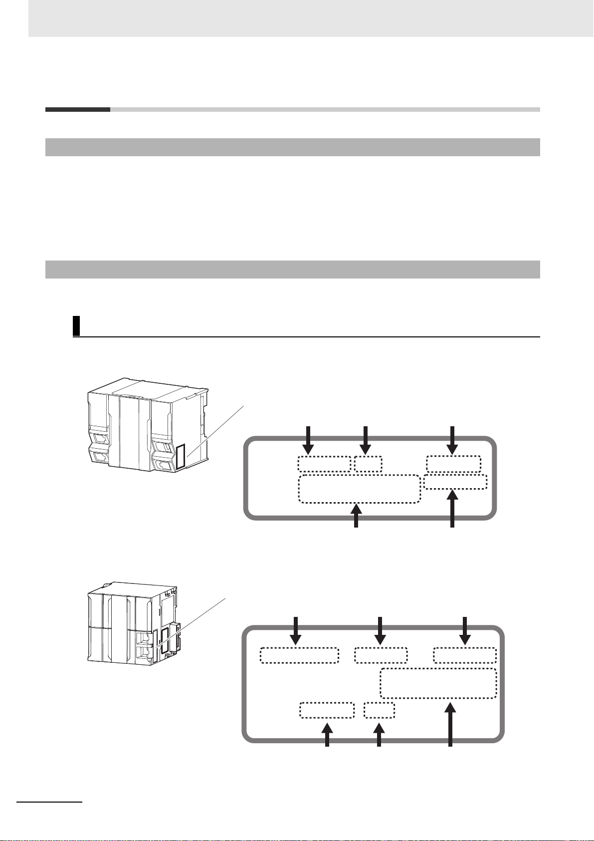
ID information indication
Lot number Serial number Unit version
MAC address Hardware revision
LOT No. DDMYY xxxx Ver.1.
PORT1 : HW Rev.
PORT2 :
ID information indication
Unit model
Lot number Serial number MAC address
Unit version Hardware revision
NJ501
-
Ver.1.
PORT1 MAC ADDRESS:
PORT2 MAC ADDRESS:
Lot No. DDMYY
xxxx
HW Rev.
Versions
Unit Versions
Hardware revisions and unit versions are used to manage the hardware and software in NJ/NX-series
Units and EtherCAT slaves. The hardware revision or unit version is updated each time there is a
change in hardware or software specifications. Even when two Units or EtherCAT slaves have the
same model number, they will have functional or performance differences if they have different hardware revisions or unit versions.
This section describes NJ/NX-series CPU Un
Checking Versions
You can check versions on the ID information indications or with the Sysmac Studio.
its an
d EtherCAT slaves as examples.
Checking Unit Versions on ID Information Indications
The unit version is given on the ID information indication on the side of the product.
The ID information on an NX-series NX701- CPU
Note The hardware revision is not displayed for the Unit that the hardware revision is in blank.
The ID information on an NJ-series NJ501- CPU Unit is shown below.
Unit is shown below.
16
Note The hardware revision is not displayed for the Unit that the hardware revision is in blank.
Sysmac Studio Drive Functions Operation Manual (I589)
Page 19
Versions
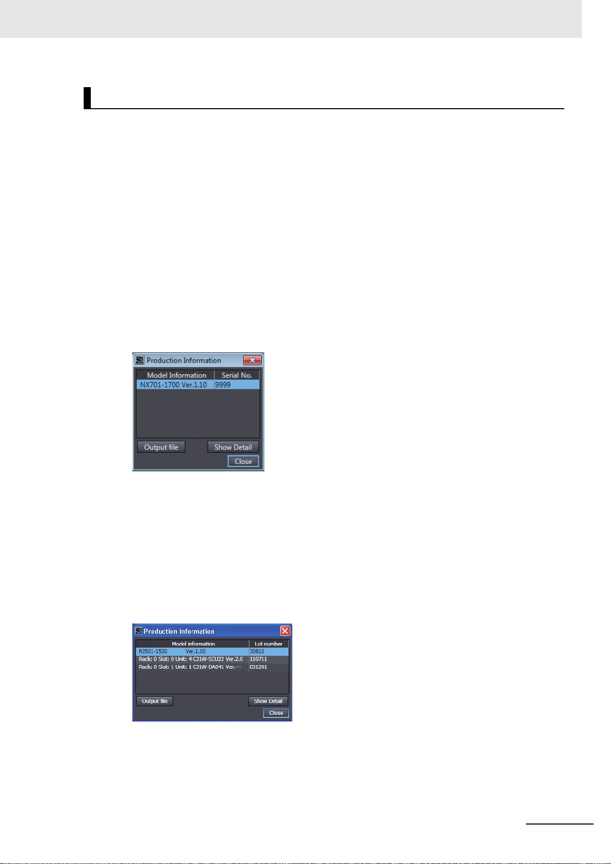
Checking Unit Versions with the Sysmac Studio
You can use the Production Information Dialog Box while the Sysmac Studio is online to check the unit
version of a Unit.
You can check the unit version of the following Units.
•CPU Units
• CJ-series Special I/O Units and CPU
• EtherCAT slaves
The unit versions of CJ-series Basic I/O
Refer to the Sysma
tion information displays.
c Studio Version 1 Operation Manual (Cat. No. W504) for details on the Unit produc-
Bus Units
Units cannot be checked from the Sysmac Studio.
NX-series CPU Units
1 Right-click CPU Rack under Configurations and Setup CPU/Expansion Racks in the Multi-
view Explorer and select Display Prod
The Production Information Dialog Box is displayed.
The unit version is displayed after Ver. to the r
uction Information.
ight of the Unit model number.
NJ-series CPU Units and CJ-series Units
1 Double-click CPU/Expansion Racks under Configurations and Setup in the Multiview
Explorer. Or, right-click CPU/Expansion Racks under Configurations and Setup and select
Edit from the menu.
The Unit Editor is displayed.
2 Right-click any open space in the Unit Editor and select Production Information.
The Production Information Dialog Box is displayed.
The unit version is displayed after Ver. to the r
ight of the Unit model number.
EtherCAT Slaves
1 Double-click EtherCAT under Configurations and Setup in the Multiview Explorer. Or,
right-click EtherCAT under Configurations and Setup and select Edit from the menu.
The EtherCAT Tab Page is displayed.
Sysmac Studio Drive Functions Operation Manual (I589)
17
Page 20

Versions
Additional Information
2 Right-click the master on the EtherCAT Tab Page and select Display Production Information.
The Production Information Dialog Box is displayed.The unit version is display
the right of the Unit model number.
• Refer to the manual for the specific Unit for the unit versions of the CPU Units to which the
database connection service and other functions were added, as well as for the unit versions
of the Communications Coupler Units, NX Units, and Safety Control Units.
• This manual sometimes refers to the unit version of the CPU Unit as the unit version of the
Controller.
Unit Versions and Sysmac Studio Versions
The functions that are supported by a Unit depend on its unit version. The version of Sysmac Studio
that supports the functions that were added for an upgrade is required to use those functions. Refer to
the NJ/NX-series CPU Unit Software User’s Manual (Cat. No. W501) for the relationship between the
unit versions of the NJ/NX-series CPU Units and the Sysmac Studio versions, and for the functions that
are supported by each unit version. Refer to the relevant manuals for the Communications Coupler Unit
and NX Units for differences in the functional support provided by each unit version.
ed after Rev. to
18
Sysmac Studio Drive Functions Operation Manual (I589)
Page 21

Related Manuals
Related Manuals
The following manuals are related. Use these manuals for reference.
Manual name Cat. No. Model numbers Application Description
Sysmac Studio Drive
Functions Operation
Manual (t
Sysmac Studio Version 1
Operation Manual
1S-ser
tors and Servo Drives
User’s Manual (with
Built-i
munications)
1S-Series AC Servomotors and Servo Drives
User’s Manual (with
Buil
munications and Safety
F
G5-series AC Servomotors and Servo Drives
User’s Manual (with
Buil
munications)
G5-series Linear
Motors/Servo Drives
User’s Manual (with
Buil
munications)
CJ1W-NC81/82
Position Control Unit
User's Manual
his manual)
ies AC Servomo-
n EtherCAT® Com-
t-i
n EtherCAT® Com-
unctionality)
n EtherCAT® Com-
t-i
n EtherCAT® Com-
t-i
I589 SYS-
MAC-SE2
W504 SY
I586 R88M-1,
I621 R88M-1
I576 R88M-K,
I577 R88L-EC-,
W487 CJ1W-NC81/82Learning about the
S-
MAC-SE2
1
SN-ECT
R88D-
AL/
1AM,
SAN-EC
R88D-1
T
K
N-ECT
R88D-
R88D-KN-ECT-L
Learning about the drive
functions of Sysm
dio.
Learning about the operating procedures and functions of Sysmac Studio
besides the drive functio
Learning about the
1S-series AC Servomotors and Servo Drives with
builtnications
Learning about the
1S-series A
tors and Servo Drives with
built-i
nications and Safety Functionality.
Learning about the
G5-series AC Servomotors and Servo Drives with
builtnications.
Learning about the
G5-series Linear Motors
and Servo Drives with
built-in EtherCAT communications.
CJ-series Position Control
Unit CJ1W-NC8.
ns.
i
n EtherCAT commu-
C
Servomo-
n EtherCAT commu-
i
n EtherCAT commu-
ac Stu-
Describes the operating procedures for the drive
s of Sysmac Studio.
function
Describes the operating procedures for other
functions of Sysmac Studio.
Describes the hardware, setting methods, and
functions of 1SServo Drives with built-in EtherCAT communications.
Describes the hardware, setting methods, and
s of 1S-
function
Servo Drives with built-in EtherCAT communications and Safety Functionality.
Describes the hardware, setting methods, and
functions of G5Servo Drives with built-in EtherCAT communications.
Describes the hardware, setting methods, and
s of G5-series Linear Motors and Servo
function
Drives with built-in EtherCAT communications.
Describes the hardware, setting methods, and
functions of CJ1W-NC8 Position Control
Unit.
series AC Servomotors and
series AC Servomotors and
series AC Servomotors and
Sysmac Studio Drive Functions Operation Manual (I589)
19
Page 22

Revision History
I589-E1-06
Revision code
Cat. No.
Revision History
A manual revision code appears as a suffix to the catalog number on the front and back covers of the
manual.
Revision code Date Revised content
01 July 2016 Original production
02 April 2017 Revisions for an upgrade to Sysmac Studio version 1.18.
03 October 2017 Revisions for an upgrade to Sysmac Studio version 1.20.
04 April 2018 Revisions for an upgrade to Sysmac Studio version 1.22.
05 July 2019 Revisions for an upgrade to Sysmac Studio version 1.29.
06 April 2020 Revisions for an upgrade to Sysmac Studio version 1.40.
20
Sysmac Studio Drive Functions Operation Manual (I589)
Page 23

Sysmac Studio Drive Functions
This section provides an overview of the Sysmac Studio drive functions and describes
its features, system configuration, and use cases.
1-1 Sysmac Studio Drive Functions . . . . . . . . . . . . . . . . . . . . . . . . . . . . . . . . . . 1-2
1-2 System Configuration . . . . . . . . . . . . . . . . . . . . . . . . . . . . . . . . . . . . . . . . . . 1-3
1-2-1 Connection to Drive . . . . . . . . . . . . . . . . . . . . . . . . . . . . . . . . . . . . . . . . . . . . 1-3
1-2-2 Applicable Drives and Communications Types . . . . . . . . . . . . . . . . . . . . . . . 1-5
1
Sysmac Studio Drive Functions Operation Manual (I589)
1 - 1
Page 24

1 Sysmac Studio Drive Functions
1-1 Sysmac Studio Drive Functions
Sysmac Studio Automation Software provides an integrated development environment to set up, program, debug, and maintain SYSMAC NJ/NX/NY-series Controllers and other Machine A
trollers, as well as EtherCAT slaves. Sysmac Studio offe
as EtherCAT slaves, for example, parameter settings, transfer, and comparison as well as test runs,
tuning, monitoring, and data tracing. These functions are collectively called “drive functions”.
This manual describes the operation procedur
es of Sysmac Stu
Support for OMRON Drives
rs various functions for specific Drives installed
dio drive functions.
utomation Con-
Easy and Secure Drive Parameter Settings
1S-series Servo Drives and G5-series Servo Drives are supported.
Parameters can be selected by specifying a category or filtering the list.
You can customize a category to make your own favorite category.
Efficient Drive Setup and Tuning Navigate
d by the Setup and Tuning
Wizard (1S Series Only)
For 1S-series Drives, the Setup and Tuning wizard is provided to perform a series of operations from
*1
basic parameter settings
and transfer, test run, and tuning to data tracing. With the wizard, you can
reduce the time required for drive settings and tuning.
*1. With the Setup and Tuning wizard for a 1S-series Drive, you can assign functions to external I/O signals (i.e.,
control I/O connectors) easily while checking the connector pin numbers and arrangement diagram.
Support of Various Tuning Methods (1S Series Only)
For 1S Series, three kinds of tuning methods are provided; easy tuning, advanced tuning, and manual
tuning.
In Easy tuning and Manual tuning, tuning can be simultaneo
• Easy tuning: Gains and filters are automatically adjusted by repeating motor operations. Use this
method when you want to perform the tuning easily.
• Advanced tuning: You can adjust gains and filters by minimum motor operations through a simulation. Gain
and filter settings can be adjusted individually.
• Manual tuning: You can adjust gains and filters at the same time by editing only one parameter.
usly performed on multiple Drives.
1 - 2
Sysmac Studio Drive Functions Operation Manual (I589)
Page 25
1-2 System Configuration
R
U
N
E
R
R
IN
L
/
A
R
8
8D
-1SN
L
/
A
F
S
O
U
T
Et
her
CA
T
ID21
1
0
1
3
2
4
5
7
6
8
9
11
1
0
12
13
14
1
5
DC
2
4
V
7
mA
C
OM
MAC
H
N
o
.
AD
04
2
R
U
N
ERC
ERH
B
1
A
1
x
1
0
1
x1
0
0
0
9
8
7
6
5
4
3
2
1
0
9
8
7
6
5
4
3
2
1
0 1 234
5
6 7
8
9
10
111213 14 15
Commercially available USB
cable or Ethernet cable
NJ/NX-series
CPU Unit
Sysmac Studio
EtherCAT
Drive
This section describes the system configuration for the functions available when Drive is selected in a
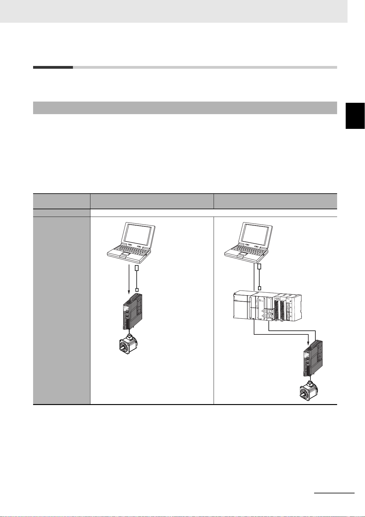
1-2-1 Connection to Drive
Connection method Direct connection via USB
Drive 1S Series and G5 Series
Sysmac Studio project.
Sysmac Studio can be connected to a Drive by the following four methods.
• Direct connection to a Drive via USB
• Connection to a Drive on an EtherCAT network thro
ugh an NJ/NX-series CPU Unit connected via
USB or Ethernet
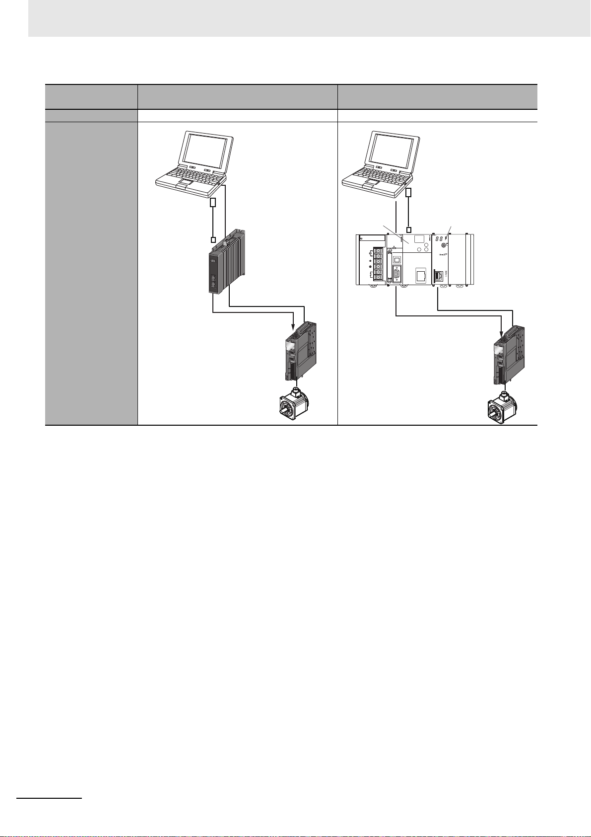
• Connection to a Drive on an EtherCAT network thro
ugh a Programmable Multi-Axis Controller con-
nected via Ethernet
• Connection to a Drive on an EtherCAT network thro
ugh a CJ-series CPU unit connected via USB or
Ethernet, equiped with a CJ1W-NC8 Position Control Unit
EtherCAT connection via an NJ/NX-series
CPU Unit
1 Sysmac Studio Drive Functions
1-2 System Configuration
1
1-2-1 Connection to Drive
Connection diagram
Sysmac Studio
Commercially available
USB cable *1
Et
R8
her
8
CA
D
T
1
SN
L
/
R
A
U
L
N
/
A
E
R
R
IN
O
U
T
F
S
Drive
*1. Refer to the manuals of each Servo Drive
for the
USB
cable.
Sysmac Studio Drive Functions Operation Manual (I589)
1 - 3
Page 26
1 Sysmac Studio Drive Functions
R
U
N
E
R
R
IN
L
/
A
R
8
8D
-1SN
L
/
A
F
S
O
U
T
Et
her
CA
T
Commercially available
Ethernet cable
Programmable
Multi-Axis
Controller
Sysmac Studio
EtherCAT
Drive
R
U
N
ER
R
IN
L
/A
R88
D-1S
N
L
/A
F
S
OU
T
E
th
e
r
C
A
T
Commercially available USB
cable or Ethernet cable
Sysmac Studio
EtherCAT
Drive
CJ-series
CPU Unit
CJ1W-NC8
Connection method
EtherCAT connection via a Programmable
Multi-Axis Controller
Drive 1S Series and G5 Series 1S Series
Connection diagram
EtherCAT connection via CJ1W-NC8
Position Controller
Refer to 2-7 Online Connection Procedure on page 2-24 for the online connection procedure with the
Drive.
1 - 4
Sysmac Studio Drive Functions Operation Manual (I589)
Page 27

1 Sysmac Studio Drive Functions
1-2-2 Applicable Drives and Communications Types
Sysmac Studio supports the following Drives. Each Drive supports the communications given in the
Device
cate-
gory
Servo
Drive
table.
Drive
name
AC
Servo
Drive
Linear
Drive
Type Model
1S-series AC
Se
rvomotors and
Servo Drives with
Built-in EtherCAT
Communications
1S-Series AC
Se
rvomotors and
Servo Drives with
Built-in EtherCAT
Communications
and Safety Functionality
G5-series AC
Se
motors and
rvo
Servo Drives with
Built-in EtherCAT
Communications
G5-series Linear
Motors and
S
ervo
Drives with
Built-in EtherCAT
Communications
Communications with Sysmac Studio
EtherCAT
Refer-
ence
manual
Direct
connec-
tion via
tion via an
NJ/NX/NY-
USB
CPU Unit
R88D-1SN-ECT I586 Possible Possible Possible Possible
R88D-1SAN-ECTI621 Possible
R88D-KN-ECT I576 Not possi-
R88D-KN-ECT-L I577 Not possi-
connec-
series
EtherCAT
connec-
tion via
Program-
mable
Multi-Axis
Controller
EtherCAT
connec-
tion via
C
-NC
J1W
8 Posi-
tion Con-
troller
ble
ble
1-2 System Configuration
1
1-2-2 Applicable Drives and Communications Types
Sysmac Studio Drive Functions Operation Manual (I589)
1 - 5
Page 28

1 Sysmac Studio Drive Functions
1 - 6
Sysmac Studio Drive Functions Operation Manual (I589)
Page 29

Overview of the Operations
This section describes the basic drive operation flow and user interfaces of Sysmac
Studio.
2-1 Basic Operation Flow . . . . . . . . . . . . . . . . . . . . . . . . . . . . . . . . . . . . . . . . . . 2-2
2-1-1 1S Series . . . . . . . . . . . . . . . . . . . . . . . . . . . . . . . . . . . . . . . . . . . . . . . . . . . . 2-2
2-1-2 G5 Series . . . . . . . . . . . . . . . . . . . . . . . . . . . . . . . . . . . . . . . . . . . . . . . . . . . . 2-6
2-2 Installation and Uninstallation . . . . . . . . . . . . . . . . . . . . . . . . . . . . . . . . . . . 2-8
2-3 Creating a Project . . . . . . . . . . . . . . . . . . . . . . . . . . . . . . . . . . . . . . . . . . . . . 2-9
2-3-1 Using a Drive with an OMRON NJ/NX/NY-series Controller . . . . . . . . . . . . . 2-9
2-3-2 Using a Drive Independently . . . . . . . . . . . . . . . . . . . . . . . . . . . . . . . . . . . . 2-10
2-4 Areas of the Application Window . . . . . . . . . . . . . . . . . . . . . . . . . . . . . . . . 2-12
2-4-1 Overview of the Application Window . . . . . . . . . . . . . . . . . . . . . . . . . . . . . . 2-12
2-4-2 Multiview Explorer . . . . . . . . . . . . . . . . .
2-4-3 Toolbar . . . . . . . . . . . . . . . . . . . . . . . . . . . . . . . . . . . . . . . . . . . . . . . . . . . . . 2-16
2-5 Project Data . . . . . . . . . . . . . . . . . . . . . . . . . . . . . . . . . . . . . . . . . . . . . . . . . 2-17
2-5-1 Project Management . . . . . . . . . . . . . . . . . . . . . . . . . . . . . . . . . . . . . . . . . . 2-17
2-5-2 Project Data . . . . . . . . . . . . . . . . . . . . . . . . . . . . . . . . . . . . . . . . . . . . . . . . . 2-18
2-5-3 Import and Export . . . . . . . . . . . . . . . . . . . . . . . . . . . . . . . . . . . . . . . . . . . . . 2-19
2-6 Functions, Use Cases, and Operation Procedures . . . . . . . . . . . . . . . . . . 2-20
2-6-1 1S Series . . . . . . . . . . . . . . . . . . . . . . . . . . . . . . . . . . . . . . . . . . . . . . . . . . . 2-20
2-6-2 G5 Series . . . . . . . . . . . . . . . . . . . . . . . . . . . . . . . . . . . . . . . . . . . . . . . . . . . 2-22
2-6-3 Function and Operation Procedures for Each Drive . . . . . . . . . . . . . . . . . . . 2-23
2-7 Online Connection Procedure . . . . . . . . . . . . . . . . . . . . . . . . . . . . . . . . . . 2-24
. . . . . . . . . . . . . . . . . . . . . . . . . . . 2-13
2
Sysmac Studio Drive Functions Operation Manual (I589)
2 - 1
Page 30

2 Overview of the Operations
2-1 Basic Operation Flow
This section describes the basic Sysmac Studio operation flows for the Drives.
2-1-1 1S Series
This section gives the basic operation flow for 1S Series.
Creating a Project
Procedure Online Offline Operation Reference
Starting Sysmac Studio and creating a new
project o
page.
n the start
Possible Possible • Setup and Tuning for Independent
Drives:
Select New Pr
in the Category field and the applicable
model number in the Device field.
Then, click the Create button.
• Using the Drive with an OMRON
N
J/NX/NY-series Controller:
After creating a project for the Controller, register the applicable model to the
EtherCAT
Sysmac Studio Version 1 Operation
Manual (Cat. No. W504) for details.)
• Using the Drive with an OMRON Programmable Multi-Axis Controller:
Select New Pr
in the Category field and the applicable
model number in the Device field.
Then, click the C
Once the drive project is created,
right-cli
ck on the drive and select Com-
munications Setup fro
Once opened, configure the Remote
connection via Programmable
Multi-Axis Controller (EtherCAT).
• Using the Drive with an OMRON
CJ-serie
CJ1W-NC8 Position Control Unit:
Select New Pr
in the Category field and the applicable
model number in the Device field.
Then, click the C
Once the drive project is created,
right-cli
munications Setup fro
Once opened, configure the Remote
connection via CJ1W-NC[]8[] Position Controller (EtherCAT).
s CPU Unit equiped with
ck on the drive and select Com-
oject, and sel
configuration. (Refer to the
, and select Drive
oject
eate button.
r
oject, and select Drive
eate button.
r
ect Drive
the menu.
m
the menu.
m
2-3 Creating a
Project on page
9
2-
2 - 2
Sysmac Studio Drive Functions Operation Manual (I589)
Page 31

2 Overview of the Operations
Setup and Tuning through Troubleshooting
Procedure
Step
1: Going online/offline with the Drive Possible Possible Select Online or
Online
Offline
Operation Reference
2-7 Online
Offline.
Connection
2-1 Basic Operation Flow
Procedure on
page 2-24
Step
2: Startup --- --- Select Setup and
Tuning.
1. Setup of an absolute encoder Possible --- Select Quick
Par
2. Function assignment to external
I/O si
gnal
s
Possible Possible
ameter Setup
and I/O Monitor
in the Setup and
Tuning wizard.
3-8 Setup and
Tuning Wizard
on page 3-36
3-8-2 Quick
Parameter
Setup and I/O
Monitor on
page 3-37
2
2-1-1 1S Series
3. Test run Possible --- 3-8-3 Test Run
and Function
Status on
page
3-45
4. Tuning
Note Refer to Tuning Method
Possible --- Select Setu
Tuning.
p and
Selection Flow on page
2-5 below for how to
select a tuning method.
Easy Tuning Possible --- Select Easy Tun-
in
g in the Setup
an
d Tuning wiz-
ard.
Advance
d Tuning Possible --- Select Advanced
Tuning in the
Setup and Tuning
3-8-4 Easy
Tuning (Single
Drive) on
page
3-48
4-1 Manual
Tuning on
page
4-2
wizard.
Ma
nual Tuning Possible --- Select Manual
Tu
ng in the
ni
Setup and Tuning
wizard.
Step
3: Detailed Settings and Tuning
1. Editing the parameters (except
for the
function assignment to
external I/O signals)
Possible Possible Double-click
Par
ameters.
3-1 Displaying
and Editing
Parameters on
page 3-2
2. Test run Possible --- Select T
est Run. 3-3 T
est Run
on page 3-18
3. Data tracing Possible --- Right-click Data
Trace Settings
and select Add -
3-6 Data Tracing o
n page
3-24
Data Trace from
the menu. Then,
double-click the
data trace created.
4. FF
T (Fast Fourier Transform)
analysis
Possible --- Double-click FFT. 4-2-1 FFT on
page 4-19
Sysmac Studio Drive Functions Operation Manual (I589)
2 - 3
Page 32

2 Overview of the Operations
Procedure
5. Damping control Possible --- Select Damping
Step
4: Status monitoring and trouble-
shooting
Online
Possible --- Select Status
Offline
Operation Reference
Control.
Monitor or Troubleshooting.
4-2-2 Damping
Control on
page 4-23
3-4 Status
Monitor on
p
age 3-22
3-5 Troubleshooting on
p
age 3-23
2 - 4
Sysmac Studio Drive Functions Operation Manual (I589)
Page 33

2 Overview of the Operations
Yes
Save to non-volatile memory
Auto tuning?
Operation OK?
Tuning through
simulation?
Operation OK?
Tuning start
Tuning complete
Easy tuning
Easy tuning
Manual tuning
Advanced tuning
Adjust each gain in the
Parameters tab page.
No
Manual tuning Fine tuning
Yes
No
Yes
No
Yes
No
Tuning Method Selection Flow
Follow this flow to select a tuning method.
2-1 Basic Operation Flow
2
2-1-1 1S Series
Sysmac Studio Drive Functions Operation Manual (I589)
2 - 5
Page 34

2 Overview of the Operations
2-1-2 G5 Series
Creating a Project
Procedure Online Offline Operation Reference
This section gives the basic operation flow for G5 Series.
Starting Sysmac Studio and creating a project on the start page.
Possible Possible • Setup and Tuning for Independent
Drives:
Select New Pr
oject, and sel
ect Drive
in the Category field and the applicable
model number in the Device field.
Then, click the Create button.
• Using the Drive with an OMRON
N
J
/NX/NY-series Controller:
After creating a project for the Controller, register the applicable model to the
EtherCAT
configuration. (Refer to the
Sysmac Studio Version 1 Operation
Manual (Cat. No. W504) for details.)
• Using the Drive with an OMRON Programmable Multi-Axis Controller:
Select New Pr
oject, and select Drive
in the Category field and the applicable
model number in the Device field.
Then, click the C
reate button.
Once the drive project is created,
right-cli
ck on the drive and select Com-
munications Setup fro
the menu.
m
Once opened, configure the Remote
connection via Programmable
Multi-Axis Controller (EtherCAT).
2-3 Creating a
Project on page
2-
9
2 - 6
Sysmac Studio Drive Functions Operation Manual (I589)
Page 35

2 Overview of the Operations
Setup and Tuning through Troubleshooting
2-1 Basic Operation Flow
Procedure Online Offline Operation Reference
Step 1: Going online/offline with the Drive
To be also executed in the subsequent
steps as
necessary.
Possible Possible
Select Online
Offline.
*1
or
2-7 Online
Connection
Procedure on
page 2-24
Step 2: Editing the parameters Possible Possible Double-click
Param
ters.
e
3-1 Displaying
and Editing
Parameters on
Step 3: Test run
Possible --- Select Test Run. 3-3 Test Run
(To be also executed in the subsequent
steps as
necessary)
Step 4: Setup of an absolute encoder Possible --- Select M
Encoder.
Step 5: Data tracing (To be also executed in the
subsequent steps as necessary)
Possible --- Right-click Data
Trace Settings
and select Add -
otor and
page 3-2
on page 3-18
tors and
3-7 Mo
Encoders on
pa
ge 3-34
3-6 Data Tracing o
n page
3-24
2
2-1-2 G5 Series
Data Trace from
the menu. Then,
double-click the
data trace created.
Step 6: Auto tu
ning
Easy tuning
Possible --- Select Auto Tun-
ing.
3-2-2 Auto Tuning for G5
Series on p
age
3-12
Step 7: FFT (Fast Fourier Transform) analysis
and d
amping control, as necessary
Possible --- Double-click FFT.
Select Damping
4-2-1 FFT on
page 4-19
Control.
Step 8: Status monitoring (To be also executed
in the earl
er steps as necessary) and
i
troubleshooting
Possible --- Select St
itor or Troubl
shooting.
atus Mon-
e-
3-4 Status
Monitor on
page 3-22
3-5 Troubleshooting on
page 3-23
*1. In the EtherCAT connection via an NJ/NX/NY-series CPU Unit, when Sysmac Studio goes online with the CPU
Unit, the online status with each Drive is established automatically.
Sysmac Studio Drive Functions Operation Manual (I589)
2 - 7
Page 36

2 Overview of the Operations
2-2 Installation and Uninstallation
Refer to the Sysmac Studio Version 1 Operation Manual (Cat. No. W504).
2 - 8
Sysmac Studio Drive Functions Operation Manual (I589)
Page 37

2-3 Creating a Project
Precautions for Correct Use
This section describes how to create a project including Drives in Sysmac Studio.
Use the following two methods to register a Drive to a project in Sysmac Studio.
• Registering a Drive as an EtherCAT slave in a project
• Registering an independent Drive in a project
2 Overview of the Operations
2-3 Creating a Project
2-3-1 Using a Drive with an OMRON NJ/NX/NY-series Controller
When you use a Drive with an OMRON NJ/NX/NY-series Controller, you register the Drive as an EtherCAT slave in a project. Register the applic
project.
able Drive to the EtherCAT configuration in the Controller
1 When creating a new project, select Controller in the Category field of the Select Device area.
Then, select an NJ/NX/NY-series CPU Unit in the Device field.
Or, add a Controller to an existing project and select
an NJ/NX/NY-series CPU Unit as Device.
2 Select the Controller that was registered in the previous step and register the applicable Drive in
the EtherCAT configuration tab page.
n
Refer to 2-5 Project Data o
project. Refer to EtherCAT Co
(Cat. No. W504) for details of the registration in the EtherCAT configuration tab page.
page 2-17 for positioning of the drive-related data in the Sysmac Studio
nfiguration and Setup of the Sysmac Studio Version 1 Operation Manual
Changing the Model of a Drive
You can change the model of a registered Drive.
1 Right-click a Drive on the EtherCAT Tab Page and select Change Model.
The Drives that you can change to are displayed in the Change Model dialog box.
2
2-3-1 Using a Drive with an OMRON NJ/NX/NY-series Controller
2 Select the Drive to change to and then click the OK button.
A dialog box that alerts you to the change o
3 Click the OK button.
The Drive is changed to the selected model and unit version.
• For G5-series unit version earlier than 2.0 (excluding Linear Servo Drives) and between different types of Servo Drives, you ca
• Any settings in the Drive before the change that are not supp
change will be lost when you change the model.
Sysmac Studio Drive Functions Operation Manual (I589)
f the model is displayed.
nnot change the model.
orted by the Drive after the
2 - 9
Page 38

2 Overview of the Operations
2-3-2 Using a Drive Independently
An independent Drive is registered to the Drive group in a project. Use the following two methods for
registration:
• Selecting Drive in the Category field of the Selec
• Adding the Driv
e to an existing project
t Device area when you create a new project
Refer to 2-5 Project Data on
page 2-17 for positioning of the drive-related data in the Sysmac Studio
project.
Refer to the Sysmac
Studio Version 1 Operation Manual (Cat. No. W504) for basic operations of Sys-
mac Studio.
Selecting a Drive as a Device when Creating a New Project
When creating a new project file, select a Drive as a device.
1 Click the New Project button in the project window.
2 In the Project Properties dialog box, enter values in the Project name, Author (optional) and
Comment (optional) fields and select the following in the Category and Device fields in the
Select Device area.
Field Item to select
Category Drive
Device Applicable Drive model
2 - 10
Note When the computer with Sysmac Studio running is directly connected to a Drive via USB, a new project
can be automatically created for the connected Drive. To do so, click the Connect to Device button
without opening a project in the above start page of Sysmac Studio. Refer to Going Online from the
Start Page of Sysmac Studio on pa
details.
ge 2-26 of 2-7 Online Connection Procedure on page 2-24 for
Sysmac Studio Drive Functions Operation Manual (I589)
Page 39

2 Overview of the Operations
3 Click the Create button at the bottom right of the Select Device area.
A new project is created and the following window is
displayed.
2-3 Creating a Project
2
2-3-2 Using a Drive Independently
Adding a Drive to an Existing Project
1 Select Drive from the Insert menu in the main menu bar.
Or, right-click Devi
ce Group in the Multiview Explorer and select Add from the menu.
2 The following Add Device dialog box is displayed. Select the applicable model number.
3 Click the OK button. The selected Drive is registered.
Changing the Model of a Registered Drive
1 Right-click a registered Drive and select Change Device from the menu.
2 The drive selection dialog box is displayed. Change the Drive to the model that you want to set.
3 Click the OK button. If the following dialog box is displayed, confirm that no problem will occur,
and then click the Yes Button.
Sysmac Studio Drive Functions Operation Manual (I589)
2 - 11
Page 40
2 Overview of the Operations
(a)
(b)
(c)
(f)
(d)
(e)
2-4 Areas of the Application Window
This section gives the names of the parts specific to Sysmac Studio.
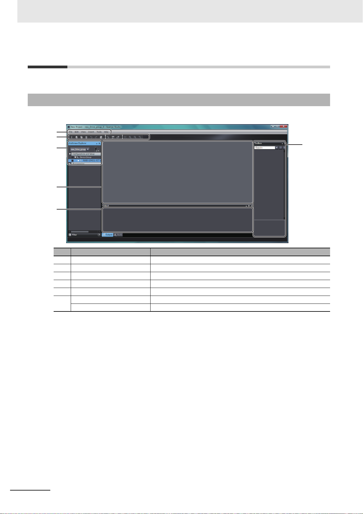
2-4-1 Overview of the Application Window
When you open a project, the following application window is displayed.
No. Name Description
(a) Menu bar Menu names are displayed in this bar.
(b) Toolbar Buttons and icons are displayed in this bar.
(c) Multiview Explorer This pane is your access point
(d) Edit pane The edit pane is used to display and edit the data for any of the items.
(e) Output tab page Operation execution status and errors are displ
(f) Toolbox Not used.
Properties pane The data trace and FFT properties are displayed in this pane.
for all Sysmac
Studio data.
a
yed in this tab page.
2 - 12
Sysmac Studio Drive Functions Operation Manual (I589)
Page 41

The following context
menu is displayed by
right-clicking a Drive.
2-4-2 Multiview Explorer
2 Overview of the Operations
2-4 Areas of the Application Window
Drive Display Position and Method
This pane is your access point for all Drive data.
Drives Independently Registered in the Project
For each Drive, its model number is displayed under Configurations and Setup - Device Group.
Drives Registered as EtherCAT Slaves in the Project
For each Drive, its node address, and model number followed by the Drive name in parentheses are
displayed under Configurations and Setup - EtherCAT.
2
2-4-2 Multiview Explorer
Operation Procedure for Each Function
The operation procedure of Sysmac Studio differs according to the functions.
Category
Functions executed from the
Multiview
Explore
r
Functions (item name/menu
name)
• Parameters
•FFT
• Data Trace Settings
Operation
Select an item from the tree structure in the Multiview
Expl
orer.
nctions exe-
Fu
cuted from the
context men
• Setup and Tuning (1S Series
*1
• Auto Tuning (G5 Series only
u
• Troubleshooting
• Status Monitor
• Motor and Encoder
•Test Run
• Damping Control
•Initialize
• Properties
only)
(both th
and linear motor type))
servomotor type
e AC
The following items
are displayed in the
Multiview Explorer.
· Parameters
· FFT
· Data Trace Settings
Right-click the Drive and select a command from the
menu.
Sysmac Studio Drive Functions Operation Manual (I589)
Refer to the following page for the differences between
Dri
v
e types.
2 - 13
Page 42

2 Overview of the Operations
Drive type 1S Series
G5 Series (Except for linear
motor type)
G5 Series (Linear motor
type)
Registered as
an EtherCAT
slave in the
project
Registered
independently in the
project
*1. Context menu displayed by right-clicking each Drive type
The context menu displayed by right-clicking each Drive differs by the Drive types as shown below.
The displayed menu also differs according to how the Drive is registered in the project, i.e., whether the Drive
is registered as an EtherCAT slave or the Drive is independently registered in the project.
2 - 14
Sysmac Studio Drive Functions Operation Manual (I589)
Page 43

2 Overview of the Operations
2-4 Areas of the Application Window
Right-click Menu Variation
Drive type
Item selected in
the Multiview
Explorer
Right-click menu Description
1S Series
Servo Drive Delete Deletes the Servo Drive. Available Available Available
Rename Changes the name of the
S
e
rvo Drive.
Available Available Available
Change Device Changes the device. Available Available Available
Setup and Tuning Performs the quick param-
Available Not availeter setup, I/O monitoring, and tuning easily.
Auto Tuning Invokes the auto tuning
fun
c
tion.
Motor Setup Sets the parameters
re
lated to the linear motor.
Troubleshooting Invokes the troubleshoot-
Not avail-
able
Not avail-
able
Available Available Available
ing function.
Status Monitor Invokes the status monitor
Available Available Available
function.
Motor and Encoder Sets up an absolute
Available Available Not availencoder.
Displa
ys the properties of
the Servomotor.
Test Run Starts a test run. Available Available Available
Damping Control Invokes the damping con-
Available Available Available
trol function.
Initialized Invokes the initialize func-
Available Available Available
tion.
Properties Displays the properties of
e Servo Drive.
th
Print Prints the Drive parame-
Available Available Available
Available Available Available
ter settings, FFT, and data
traces
.
Online/Offline Goes online with the con-
Available Available Available
nected Servo Drive.
Direct connection
(USB)
Directly connects to the
Drive th
rough a USB
Available Available Available
cable. This menu command can be executed
when
the Drive is regis-
tered as an EtherCAT
Communications
Setup
sl
ave in the proj
Configures connection
type and settings. This
ect.
Available Available Available
menu command can be
executed when the Drive
is independently registered in the project.
Parameters Edit Edits the parameters. Available Available Available
FFT Edit Invokes the FFT fu
nct
ion. Available Available Available
G5 Series
(Except for
linear
motor
type)
G5 Series
(Linear
motor
type)
Not avail-
able
able
Available Available
Not avail-
Available
able
able
2
2-4-2 Multiview Explorer
Sysmac Studio Drive Functions Operation Manual (I589)
2 - 15
Page 44

2 Overview of the Operations
Item selected in
the Multiview
Explorer
Data
Trace
Settings
Data
Trace
Right-click menu Description
Add - Data Trace Adds a data trace. Available Available Available
Edit Edits a data trace.
Cut Cuts a data trace.
Copy Copies a data trace.
Delete Deletes a data trace.
2-4-3 Toolbar
Refer to the Sysmac Studio Version 1 Operation Manual (Cat. No. W504) for details.
1S Series
Drive type
G5 Series
(Except for
linear
motor
type)
G5 Series
(Linear
motor
type)
2 - 16
Sysmac Studio Drive Functions Operation Manual (I589)
Page 45

2-5 Project Data
Project data
Data related to NJ/NX/NY
-series Controllers
(Controller group)
Data related to FH Sensor
Controllers
(Vision Sensor group)
Data related to Drives
(Drive group)
Data related to other devices
such as Slave Terminals
2 Overview of the Operations
This section describes project data related to Drives.
2-5-1 Project Management
Sysmac Studio manages configuration information of the devices such as Controllers, Drives, and
Vision Sensors on a project basis.
2-5 Project Data
2
2-5-1 Project Management
Sysmac Studio Drive Functions Operation Manual (I589)
2 - 17
Page 46

2 Overview of the Operations
2-5-2 Project Data
Each Drive can be registered to the following two kinds of groups in project data.
• Drive group
• Controller group
Project data
Drive group
Drive A
Parameters
FFT
Data Trace
Settings
As project data, these groups' data is collective
Drive B
Parameters
FFT
Data Trace
Settings
Drive X
Parameters
FFT
Data Trace
Settings
ly managed with other groups' data.
Project data is saved in a specific area of the computer.
When you need a data file, export the project file. Refer to the Sysmac
ual (Cat. No. W504) for details.
Drive Group
Up to 128 Drives can be registered in a single project file.
The following data of all Drives is manage
• Parameters
• Trace settings and the latest data trace results
•
FFT settings and the latest FFT results
d as a Drive group in the Sysmac Studio project data.
Controller group
Vision Sensor group and
others
Studio Version 1 Operation Man-
2 - 18
Controller Group
Up to 512 Drives can be registered as EtherCAT slaves per EtherCAT network in a single project file.
The following data of each Drive is managed as an Ethe
mac Studio project data.
• Parameters
• Trace settings and the latest data trace results
FFT settings and the latest FFT results
•
rCAT slave for the Controller group in the Sys-
Sysmac Studio Drive Functions Operation Manual (I589)
Page 47

2-5-3 Import and Export
For data exchange with external devices, each Drive data file and project file can be exported and
imported in a specific or general-purpose format.
Exportable Files
2 Overview of the Operations
2-5 Project Data
File type Extension Contents Operation procedure
Drive
meter
para
file
Data trace
file
*.drvp Parameter data of each Drive in a
specific fo
rmat for Sysmac Studio
drive functions
*.csv Trace settings, latest data trace
results, an
Drive parameter data
d
Display the Parameters tab page and click
the Export bu
tton. Select Drive Parameters
(*.drvp) in the file type field.
Display the Data Trace tab page and click
the Export bu
tton in the Toolbar.
2
2-5-3 Import and Export
at the time of measurement
FFT file *.csv
*.drvfft
Project file *.smc2,
*.csm2,
*.smc
,
FFT settings, FFT measurement
*1
results, and drive parameter data
at the time of measurement
Same contents as the projects
saved by
Sysmac Studio
Display the FFT tab page and click the
Export bu
tton in the Toolbar.
Select Export from the File menu.
*.csm
*1. Drive FFT (*.drvfft) format is only supported for 1S-series Servo Drives.
Importable Files
Sysmac Studio can export the following files.
Sysmac Studio can import the following files.
File type Extension Contents Operation procedure
Drive
para
file
meter
*.drvp Parameter data of each Drive in a
specific fo
rmat for Sysmac Studio
drive functions
.csv Parameter data of each Drive
Data trace
file
FFT file
*1
expo
*.csv Trace settings and trace opera-
tion results
*.drvfft FFT settings, FFT measurement
from CX-Drive
rted
results, and drive parameter data
at the time of measurement
Project file
*2
*.smc2,
*.csm2,
,
*.smc
Same contents as the projects
saved by
Sysmac Studio
*.csm
*1. Drive FFT (*.drvfft) format is only supported for 1S-series Servo Drives.
*2. When importing project file created with a higher Sysmac Studio version, the unsupported features will be
reported via Output window.
Display the Parameters tab page and click
the Imp
ort button. Select Drive Parameters
(*.drvp) in the file type field.
Display the Parameters tab page and click
the Import button. Select CX-Drive file
(*.csv) in the file type field.
Display the Data Trace tab page and click
the Impo
rt button in the Toolbar.
Display Advanced Tuning Step 2 Frequency
Re
sponse Simulation tab page and click the
Import button.
Select Import from the File menu.
Sysmac Studio Drive Functions Operation Manual (I589)
2 - 19
Page 48

2 Overview of the Operations
2-6 Functions, Use Cases, and Operation
Procedures
This section describes operation procedures and reference sections in this manual for each function
and use case.
2-6-1 1S Series
Functional cat-
egory
Parameter editing, transfer,
an
mparison
d co
Absolute
en
coder
Test run Perform a test run while setting
Description is provided separately fo
r 1S Ser
Use case Operation procedure Reference
Set only motor rotation direction and
funct
on assignment to external I/O
i
signals for startup.
T
ransfer motor rotation direction and
functi
on assignment to external I/O
signals to a Drive.
Set not only the basic parameters,
b
t also other parameters.
u
Transfer parameters to a Drive.
Compare parameters between Sys-
mac Studio and Drive.
Set up an absolute encoder including the usage setting.
Set up an absolute encoder again
cause an encoder cable was dis-
be
connected and an alarm was activated while using the absolute
e
ncoder.
Just reset an error related to an
ab
lute encoder.
so
ba
sic parameters.
Check whether the motor can run
after startup.
heck the motor rotation direction
C
afte
r startup.
Perform jogging after startup.
ies and G5 Series.
Right-click the Drive and select
Se
tup and Tuning from the menu.
Select Quick Parameter Setup and
I/O Monitor.
Double-click Parameters in the Multiview Explorer.
Right-click the Drive and select
Setup and Tuning from the menu.
Select Quick Parameter Setup and
I/O Monitor.
Right-click the Drive and select
Motor and Encoder. Then, select
Encoder Properties.
Right-click the Drive and select
Setup and Tuning from the menu.
Select Quick Parameter Setup and
I/O Monitor.
Right-click the Drive and select Test
Run from the menu.
3-8-2 Quick
Parameter
Setup and I/O
Monitor o
3-37
3-1 Displaying
and Editing
Parameters on
page 3-2
3-8-2 Quick
Parameter
Setup and I/O
Monitor o
3-37
3-7-2 Encoder
Properties on
pa
3-8-2 Quick
Parameter
Setup and I/O
Monitor o
3-37
3-8-3 Test Run
and Function
Status o
3-45
n page
n page
ge 3-35
n page
n page
2 - 20
Sysmac Studio Drive Functions Operation Manual (I589)
Page 49

2 Overview of the Operations
2-6 Functions, Use Cases, and Operation
Functional cat-
egory
Tuning Automatically adjust the gains easily
by repeating motor operations.
Ch
Adjust damping control.
Make adjustments by the minimum
motor operation through a simulation. (Advanced tuning)
Ad
just the gains at the same time by
setting the machine rigidity parameter. (Manual tuning)
Data tracing Start a data trace and display the
wa
vefo
Drive. (Especially after advanced
tuning or manual tuning or after a
transfer of changed parameters)
FF
T (Fast Fou-
rier Transform)
Damping control Suppress vibration because work-
St
atus monitor Check online status parameters for
Troubleshooting Check the current alarms detected
Drive initialization
Drive properties Check the model and version of the
Moto
r properties Check the model and version of the
Analyze the waveforms of machine
characteristic
because machine resonance occurs
in a specific place.
pieces are vibrated when the motor
is runn
Set the damping control based on
the vibration frequency detected by
Sysmac Studio.
the Drive.
for the Drive connected online.
Return all parameters of the Drive
connected on
tings.
Drive connected online.
motor connecte
Use case Operation procedure Reference
eck auto tuning results.
rm of trace data stored in the
elocity frequency
s for v
ing.
line to the factory set-
d online.
Right-click the
Drive and select
Setup and Tuning f
rom the
menu.
Right-click Da
the Multiview Explorer and select
Add - Data Trace from the menu.
Then, double-click the data trace.
Double-click FF
Explorer.
Right-click the Drive and select
D
ing Control from the menu.
amp
R
ight-click the Drive and select Sta-
tus Monitor from the me
Right-click the Drive and select
Troubleshooting from the menu.
Right-click the Drive and select In
tialize from th
Right-click the Drive and select
Properties from the menu.
Right-click the Drive and select
Motor and Encoder from the menu,
and then select Motor Properties.
Select Easy
Tuning.
Select
Ad
vanced Tun-
ing.
Select Manual
Tu
ning.
ta Trace Settings in
T in the Multiview
nu.
e menu.
i-
3-8-4 Easy Tuning (Single
Drive) on pa
3-48
4-1 Manual Tuning on
3-6 Data Tracing on
3-24
4-2-1 FFT on
page 4-19
4-2-2 Damping
Control on page
4-23
3-4 Status Monitor on page 3-22
3-5 Troubleshooting on
page 3-23
5-1 Initialization
of the Drive on
page 5-2
5-2 Drive Properties on page
5-3
3-7-1 Motor
Properties on
pag
e 3-34
ge
page 4-2
page
Procedures
2
2-6-1 1S Series
Sysmac Studio Drive Functions Operation Manual (I589)
2 - 21
Page 50

2 Overview of the Operations
2-6-2 G5 Series
Functional cat-
egory
Parameter editing and transfer
Absolute
encoder setti
Test run Check whether the motor can run. Right-click the Drive and select Test
Data tracing Start a data trace and display the
T
uning Perform auto tuning easily. Right-click the Drive and select
T (Fast Fou-
FF
rier Transform)
analysis
Damping control Suppress vibration because work-
Status mon
Troubleshooting Check the current alarms detected
Linear motor
settings
Drive
initializa-
tion
Drive properties Check the model and version of the
Motor prope
Set parameters. Double-click Parameter
Transfer parameters to a Drive.
Compare parameters between Tool
and Drive.
Set up an absolute encoder when
ngs
using it.
Set up an absolute encoder again
b
cause an encoder cable was dis-
e
connected and an alarm was activated while using the absolute
e
ncoder.
Just reset an error related to an
absolute encoder.
Check the motor rotation direction.
Perform jogging.
a
veform of trace data stored in the
w
Drive.
An
alyze the waveforms of machine
characteristics for velo
because machine resonance occurs
in a specific place.
pieces are vibrated when the motor
is ru
ing.
nn
itor Check online status parameters for
the D
rive.
for the Drive connecte
Use a G5-series Linear Motor. Right-click the Drive and select
Return all parameters of the Drive
connected
tings.
D
r
ive connected online.
rties Check the model and version of the
motor conn
Use case Operation procedure Reference
s in the Mul-
tiview Explorer.
3-1 Displaying
and Editing
Parameters on
page 3-2
Right-click the Drive and select
Motor and Encoder. Then, select
Encoder Properties.
3-7-2 Encoder
Properties on
pa
ge 3-35
3-3 Test Run on
Run from the menu.
Right-click Da
ta Trace Settings in
the Multiview Explorer and select
Add - Data Trace from the menu.
page 3-18
3-6 Data Tracing o
n page
3-24
Then, double-click the data trace.
3-2-2 Auto Tun-
Au
ning from the menu.
to Tu
ing for G5
Series on
3-12
ty frequency
ci
Double-click FF
Explorer.
Right-click the Drive and select
Damping Contr
T in the Multiview
l from the menu.
o
4-2-1 FFT on
page 4-19
4-2-2 Damping
Control on page
4-23
d online.
Right-click the Drive and select Sta-
tus Monitor from
the menu.
Right-click the Drive and select
Troubleshooting from the menu.
3-4 Status Monitor on page 3-22
3-5 Troubleshooting on
page 3-23
4-3 Motor Set-
Mot
or Setup from the menu.
tings (only for
Linear Motor
Type of G5
Series) on page
4-27
online to the factory set-
Right-click the Drive and select Ini-
tialize from the menu.
5-1 Initialization
of the Drive on
page 5-2
Right-click the Drive and select
Properties from the menu.
5-2 Drive Properties on page
5-3
3-7-1 Motor
Properties on
pa
ge 3-34
ected online.
Right-click the Drive and select
Motor and Encoder from the menu,
and then select Motor Properties.
page
2 - 22
Sysmac Studio Drive Functions Operation Manual (I589)
Page 51

2 Overview of the Operations
2-6-3 Function and Operation Procedures for Each Drive
2-6 Functions, Use Cases, and Operation
The following table gives the supported functions and their operation procedures for each Drive.
Operation procedure (Item name and menu name)
Drive
1S Series
Functional category
Parameter editing Setup and Tuning or
eters
Param
Parameter transfer and
comparison
Parameters (Some
parameters can be trans-
G5 Series (Except for
linear motor type)
Parameters
Parameters
G5 Series (Linear motor
type)
ferred to a Drive from the
Setu
p and
Tuning wiz-
ards.)
Absolute encoder settings Setup and Tuning or
otor and Encoder
M
Test run Setup and Tuning or Test
Motor and Encoder
Test Run
Run
Tuning Setup and Tuning - Easy
to Tuning
Au
Tuning, Advanced Tuning, or Ma
nual Tuning
Data tracing Data Trace Settings
Troubleshooting Troubleshooting
Status monitoring Status Monitor
FFT (Fast Fourier Trans-
FFT
form) analysis
Damping control Damping Control
Linear motor settings None None Motor Setup
Drive initialization Initialize
Drive properties Properties
Procedures
2
2-6-3 Function and Operation Procedures for Each Drive
Sysmac Studio Drive Functions Operation Manual (I589)
2 - 23
Page 52

2 Overview of the Operations
2-7 Online Connection Procedure
This section describes how to go online with a Drive.
You can use the following four connection methods to
connect Sysmac Studio online with a Drive.
• Direct connection via USB
• EtherCAT connection via an NJ/NX/NY-series CPU Unit
• EtherCAT connection via a Programmable Multi-Axis Controller
• EtherCAT connection via CJ1W-NC8 Posi
You can perform the online connection after open
tion Controller
ing a project file or from the start page of Sysmac Stu-
dio.
The following table shows the availability of the c
Timing
After opening a project file
From the start page
of Sysmac Stu
io
d
Direct connection
via USB
Possible Possible Possible Possible
Possible Not possible Possible Possible
onnection methods in each case.
Connection method
EtherCAT connec-
tion via an
NJ/NX/NY-series
CPU Unit
EtherCAT connec-
tion via a Program-
mable Multi-Axis
Controller
EtherCAT connec-
tion via
CJ1W-NC8
Posi
tion Controller
2 - 24
Sysmac Studio Drive Functions Operation Manual (I589)
Page 53

2 Overview of the Operations
Precautions for Correct Use
2-7 Online Connection Procedure
Going Online after Opening a Project File
Direct Connection via USB
There is no need to make the communications settings.
1 Select a Drive while editing a project.
2 For a Drive that is independently registered in the project, right-click the Drive and select Online
from the menu.
For a Drive that is registered as an EtherCAT slave in the pro
Direct Connection (USB) - Online from the menu.
ject, right-click the Drive and select
2
Make sure that Sysmac Studio is offline when the USB cable is plugged in or out from the
Drive.
EtherCAT Connection via an NJ/NX/NY-series CPU Unit
1 Register the NJ/NX/NY-series Controller as a device in the project.
2 Register the Drive in the EtherCAT network of the Controller.
Refer to the Sysmac
EtherCAT Connection via a Programmable Multi-Axis Controller
Studio Version 1 Operation Manual (Cat. No. W504) for details.
1 Select a Drive while editing a project.
2 Right-click the Drive and select Communications Setup from the menu.
3 Set Connection type to Remote connection via Programmable Multi-Axis Controller (Ether-
CAT).
4 Configure Connection settings according to the Controller and Drive to go online with.
5 Press OK.
6 Right-click the Drive and select Online from the menu.
EtherCAT connection via CJ1W-NC8 Position Controller
1 Select a Drive while editing a project.
2 Right-click the Drive and select Communications Setup from the menu.
3 Set Connection type to Remote connection via CJ1W-NC8 Position Controller (Ether-
CAT).
4 Configure Connection settings according to the Controller and Drive to go online with.
5 Press OK.
6 Right-click the Drive and select Online from the menu.
Sysmac Studio Drive Functions Operation Manual (I589)
2 - 25
Page 54

2 Overview of the Operations
Additional Information
Going Online from the Start Page of Sysmac Studio
Direct Connection via USB
1 Click the Connect to Device button without opening a project on the start page of Sysmac Stu-
dio.
2 Select Drive in the Device area and click the Connect button.
Sysmac Studio is automatically con
ated for the detected Drive.
You can also perform the direct connection via USB from the EtherCAT configuration tab page.
EtherCAT Connection via a Programmable Multi-Axis Controller
nected to the Drive and a new project is automatically cre-
1 Click the Connect to Device button without opening a project on the start page of Sysmac Stu-
dio.
2 Select Drive in the Device area.
3 Select Remote connection via Programmable Multi-Axis Controller (EtherCAT) in the Con-
nection type area.
4 Configure the Connection settings according to the Controller and Drive to go online with.
5 Click the Connect button.
Sysmac Studio is automatically con
created for the detected Drive(s).
EtherCAT connection via CJ1W-NC8 Position Controller
nected to the Drive(s) and a new project is automatically
1 Click the Connect to Device button without opening a project on the start page of Sysmac Stu-
dio.
2 Select Drive in the Device area.
3 Select Remote connection via CJ1W-NC8 Position Controller (EtherCAT) in the Con-
nection type area.
4 Configure the Connection settings according to the Controller and Drive to go online with.
5 Click the Connect button.
EtherCAT Connection via an NJ/NX/NY-series CPU Unit
Connection is not possible.
2 - 26
Sysmac Studio is automatically con
created for the detected Drive(s).
nected to the Drive(s) and a new project is automatically
Sysmac Studio Drive Functions Operation Manual (I589)
Page 55

Basic Servo Drive Operations
This section describes basic operations of Servo Drives such as parameter editing,
auto tuning, and troubleshooting.
3-1 Displaying and Editing Parameters . . . . . . . . . . . . . . . . . . . . . . . . . . . . . . . 3-2
3-1-1 Displaying and Editing Drive Parameters . . . . . . . . . . . . . . . . . . . . . . . . . . . . 3-2
3-1-2 Displaying and Editing Multi-drive Parameters (Drive Setting Table) . . . . . . . 3-9
3-2 Auto Tuning . . . . . . . . . . . . . . . . . . . . . . . . . . . . . . . . . . . . . . . . . . . . . . . . . 3-11
3-2-1 Auto Tuning for 1S Series . . . . . . . . . . . . . . . . . . . . . . . . . . . . . . . . . . . . . . 3-11
3-2-2 Auto Tuning for G5 Series . . . .
3-3 Test Run . . . . . . . . . . . . . . . . . . . . . . . . . . . . . . . . . . . . . . . . . . . . . . . . . . . . 3-18
3-4 Status Monitor . . . . . . . . . . . . . . . . . . . . . . . . . . . . . . . . . . . . . . . . . . . . . . . 3-22
3-5 Troubleshooting . . . . . . . . . . . . . . . . . . . . . . . . . . . . . . . . . . . . . . . . . . . . . . 3-23
3-6 Data Tracing . . . . . . . . . . . . . . . . . . . . . . . . . . . . . . . . . . . . . . . . . . . . . . . . . 3-24
3-7 Motors and Encoders . . . . . . . . . . . . . . . . . . . . . . . . . . . . . . . . . . . . . . . . . 3-34
3-7-1 Motor Properties . . . . . . . . . . . . . . . . . . . . . . . . . . . . . . . . . . . . . . . . . . . . . . 3-34
3-7-2 Encoder Properties . . . . . . . . . . . . . . . . . . . . . . . . . . . . . . . . . . . . . . . . . . . . 3-35
3-8 Setup and Tuning Wizard . . . . . . . . . . . . . . . . . . . . . . . . . . . . . . . . . . . . . . 3-36
3-8-1 Overview . . . . . . . . . . . . . . . . . . . . . . . . . . . . . . . . . . . . . . . . . . . . . . . . . . . . 3-36
3-8-2 Quick Parameter Setup and I/O Monitor . . . . . . . . . . . . . . . . . . . . . . . . . . . 3-37
3-8-3 Test Run and Function Status . . . . . . . . . . . . . . . . . . . . . . . . . . . . . . . . . . . 3-45
3-8-4 Easy Tuning (Single Drive) . . . . . . . . . . . . . . . . . . . . . . . . . . . . . . . . . . . . . . 3-48
3-8-5 Easy Tuning (Multiple Drives) . . . . . . . . . . .
. . . . . . . . . . . . . . . . . . . . . . . . . . . . . . . . . . 3-12
.
. . . . . . . . . . . . . . . . . . . . . . . . 3-59
3
Sysmac Studio Drive Functions Operation Manual (I589)
3 - 1
Page 56

3 Basic Servo Drive Operations
(a)
(b)
(c)
(d)
(e)
3-1 Displaying and Editing Parameters
This section describes how to display and edit drive parameters.
3-1-1 Displaying and Editing Drive Parameters
Displaying Parameters
Right-click Parameters in the Multiview Explorer and select Edit from the menu. The following
parameter editor is displayed.
Parts of the editor
Column Description
(a) Upper toolbar Buttons to export/import parameter values to/from an individual drive
paramet
(b) Parameter category Select the parameters to display/edit by specifying a category, User
Selection category, or a control mode.
• The default selection is All parameters.
• You can register only the necessary parameters
(c) Parameter list OD
Description Parameter names (or object names).
Value Values of the parameters being edited in Sysmac Studio.
Drive Value Values of the parameters stored in the Drive conn
Default Default values of the parameters stored in the Drive connected online.
Range Valid ranges for the parameter values.
Units Units of the parameter values.
Data Attributes Symbols that show parameter attributes.
(d) Help Information on the currently displayed parameter.
(e) Lower toolbar Buttons to transfer all or selected pa
*1. Indicates object dictionaries (abbreviated as "OD") for the EtherCAT slave types of Drives. "Object dictio-
nary" refers to data specifications of the parameters and control information of EtherCAT slaves.
Index numbers ((Index).(Subindex)) of parameters
Refer to Attribute Symbols on pag
compare all parameters with the ones in the Drive.
er file.
tion category.
to the User Selec-
*1
in the Drive.
ected onl
e 3-3 described later for details.
rameters
to/from the Drive or
ine.
3 - 2
Sysmac Studio Drive Functions Operation Manual (I589)
Page 57

3 Basic Servo Drive Operations
Additional Information
Attribute Symbols
Refer to operational manual of each drive.
Selecting Parameters to Display
Select the drive parameters to display according to your purpose.
1 Selecting the Category to Display
Select All Categories and th
eter list.
en a category from the drop-down list displayed above the param-
3-1 Displaying and Editing Parameters
3
3-1-1 Displaying and Editing Drive Parameters
The parameters can be selected and displayed accord
ing to the categories predefined for each
Drive series.
Category list for 1S Series
Category name Description
▼All parameters All parameters
User Selection Parameters registered in the User Selection category
Categories Parameters in all
▼All
Start-up Parameters related to bas
Sysmac Common Common parameters to Sysmac
▼Control Loop Adjustment Parameters related
TDF Position Control Gains under 2-degree-of-freedom mode Position Control
TDF Velocity Control Gains under 2-degree-of-freedom
ODF Position Control Gains under 1-degree-of-freedom mode Position Control
ODF Velocity Control Gains under 1-degree-of-freedom mode
Torque Control Gains under Torque Control, regardless of the control method
ntrol System Control-related parameters
▼Co
C
ontrol Mode Area Parameters in all control modes
Control Method Area Parameters related to control methods
and 2-degree-of-freedom)
Control Loop Area Parameters related to the Drive's gains
Torque Output Area Parameters related to torque compensation and filters
Homing Area Parameters related to homing
Applied Functions Area Parameters related to other applied functions
c
▼Interface obje
Warnings or Errors Area Parameters related to warnings and
Monitoring Area Parameters related to monitoring system for the
Display Area Parameters related to the 7-segment LED indicator
Power Device Area Parameters related to the power d
Encoder Area Parameters related to the encoder
ts Parameters related to the Drive's interfaces
supply and regeneration)
categories
ic setup
to the Servo Drive's gain adjustment
mode
Velocity Control
Velocity Control
(1-degree-of-freedom
errors
Servo Drive
evice (main circuit power
Sysmac Studio Drive Functions Operation Manual (I589)
3 - 3
Page 58

3 Basic Servo Drive Operations
Category name Description
Analog Input and Output Area Parameters for the I/O interfaces
▼All Control Modes Para
Cyclic synchronous position mode Parameters related to cyclic synchronous position mode
Cyclic synchronous velocity mode Parameters related to cyclic synchronous veloci
Cyclic synchronous torque mode Parameters related to cyclic synchronous torque mode
Profile position mode Parameters related to profile position mode
Profile velocity mode Parameters related to profile velocity mode
Homing mode Parameters related to homing mode of the Servo Drive
meters in all control modes
ty mode
Category name Description
▼All parameters All parameters
User Selection Parameters registered in the User Selection category
l Categories Para
▼Al
CiA 402 Drive Profile Parameters related to CiA402
Pn0xx: Basic Parameters Basic parameters
Pn1xx: Gain Parameters Gain-related parameters.
Pn2xx: Vibration Suppression Parame-
ters
Pn3xx: Analog Control Parameters Analog-related parameters
Pn4xx: I/F Monitor Setting Parameters I/O-related parameters
Pn5xx: Extended Parameters Extended parameters
Pn6xx: Special Setting 1 Parameters Special-purpose parameters other than above
Pn7xx: Special Setting 2 Parameters Special-purpose parameters other than above
Pn8xx: Special Setting 3 Parameters Special-purpose parameters other than above
All Control Modes Parameters related to all control modes
meters in all categories
Parameters related to the filters that suppress vibration
2 Using the User Selection List to Select and Display only the Necessary Parameters.
Use the User Selection list to select and display the frequently used parameters only.
Category list for G5 Series
3 - 4
(1) Adding a parameter to the User Selection list.
ht-click the parameter in the parameter editor and select Add to
Rig
'User Selection' from
the menu. If there are multiple lists, select the list to which the selected parameter is added.
Use the Shift key or Ctrl ke
y to select and add more than one parameter at the same time.
(2) Deleting a parameter from the User Selection list.
After selecting the User Se
lection from the drop-down list, right-click the parameter and
select Remove from 'User Selection' from the menu. If there are multiple lists, select the
list from which the selected parameter is removed.
e
Use the Shift k
y or Ctrl key to select and delete more than one parameter at the same
time.
Sysmac Studio Drive Functions Operation Manual (I589)
Page 59
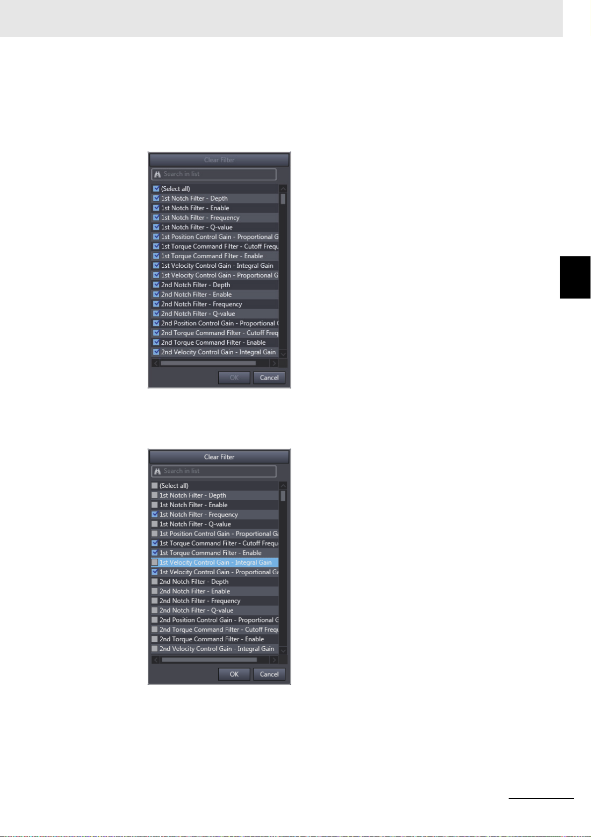
3 Basic Servo Drive Operations
3 Using the Filtering Function to Select and Display only the Necessary Parameters.
(1) Filtering by specifying a search string
The parameters whose name contains the specified text string are displayed. Click
black down-pointing triangle (▼) symbol displayed in the header of the column and enter
the search string in the entry field displayed on the upper part.
3-1 Displaying and Editing Parameters
the
3
3-1-1 Displaying and Editing Drive Parameters
(2) Filtering by directly selecting the
The parameters selected from the list are displayed. Click the black down(▼) symbol displayed in the header of the column and select the necessary parameters
from the list.
necessar
y parameters from the list
pointing triangle
Sysmac Studio Drive Functions Operation Manual (I589)
3 - 5
Page 60

3 Basic Servo Drive Operations
Displaying the Right-click Menu
The following table gives a list of menu commands displayed when a parameter is right-clicked and
functions of the menu commands.
Menu command Description
Add to 'User Selection' Registers the selected parameters to the User Selection category.
Remove from 'User Selection' Deletes the selected parameters from
Organize 'User Selection' User Selection lists can be customized
Select All Selects all the currently displayed parameters.
Reset Selection Initializes the selected parameters.
Selection to Drive Downloads the selected parameters from the compu
Selection from Drive Uploads the selected parameters from the D
Copy Copies the selected parameters.
Paste Pastes the selected parameters.
the User Selection category.
with following operations: creation of new lists, renaming and deletion of existing lists,
ing/importing lists.
ter (i.e., Sysmac
Studio) to the Drive.
rive to the computer (i.e.,
Sysmac Studio).
and export-
Editing Parameters
1 Entering a Parameter
• Entering a value directly in the parameter editor.
Click the Value colu
The changed values are indicated in purple. If a value is out of range or invalid, it is indicated in
red.
•
Copy & Paste
Copy and paste a parameter value in the parameter editor.
Note Parameters cannot be copied and pasted between an external editor and the parameter editor.
• Export & Import
You can export/import the paramete
• The parameters are exported to a .drvp file.
• The drive project can be imported only when its d
those of the exported file.
Execute each function by clicking the followi
Button Name Description
mn of the parameter and set a value.
r list to/from a file.
rive model and version are the same as
ng buttons in the upper toolbar.
Export Saves all parameter values to a drive parameter (drvp) file.
3 - 6
Import Loads all parameter values from a drive parameter (drvp) file.
Sysmac Studio Drive Functions Operation Manual (I589)
Page 61

2 Checking the Parameter Status
3 Basic Servo Drive Operations
Check the present value status with the status icons displayed in the leftmost column of the
parame
ter editor.
3-1 Displaying and Editing Parameters
Status icons
Status icon Value status
The present value matches the default value.
The present value matches the default value, but does not match the value stored in
the Drive.
The present value does not match the default value.
The present value does not match the default val
The present value is invalid. (The value is out of range or the data type does not
match.)
The present value is invalid and does not match the
Read only. The status of the Drive is displayed.
ue nor the value stored in the Drive.
value stored in the Drive.
3
3-1-1 Displaying and Editing Drive Parameters
3 Returning the Parameters to their Default Values.
Parameters can be reset to their default values. Click
toolbar to perform a Reset operation:
Button Name Description
Reset Selection Returns the values of the selected parameters to their
default values.
Reset All Returns the values of all parameters to their default val-
ues.
one of the following buttons in the lower
Sysmac Studio Drive Functions Operation Manual (I589)
3 - 7
Page 62

3 Basic Servo Drive Operations
Precautions for Safe Use
Additional Information
Transferring Parameters to the Drive (Available Only While Online)
Parameters can be transferred to and from the Drive to refresh the parameter editor or display the
comparison results. Execute each function by clicking the following buttons in the lower toolbar.
Button Name Description
Transfer Selection to Drive Transfers the values of the selected parameters from Sysmac
Transfer Selection from Drive Transfers the values of the selected parameters from the con-
Transfer All to Drive Transfers the values of all parameters from Sysmac Studio to
Studio to the connected Drive. Use the Shift key or the Ctrl
key to select more than one parameter at the same time.
nected Drive to Sysmac Studio. Use the Shift key or
key to select more than one parameter at the same time.
the connected Drive.
the Ctrl
Transfer Al
Compare Compares the values of all parameters in Sysmac Studio with
Update Drive Settings with
Estimated Valu
l from Drive Transfers the values of all parameters from the connected
Dri
e to Sysmac Studio.
v
es
the val
dates the Drive settings with the inertia ratio, torque com-
Up
pensation, notch filter values estimated during the motor operation. This operation can be executed only
ves.
Dri
red in the connected Drive.
ues sto
for 1S-series Servo
Restarting the Drive (Available Only While Online)
The Servo Drive can be restarted from the parameter editor. This operation is available only for the
1S-series Servo Drives using any connection other than EtherCAT via CJ1W-NC8 Position Controller.
Click the Restart ( ) button in the upper toolbar to restart the drive.
• When you restart a Servo Drive, the ESM state of the Servo Drive will change in the following
order: Operational
• By the above state transition, the commands to the Servomotor
is running, make sure to stop the operation before executing the restart operation.
• When you use the NJ/NX/NY-series, the Controller will enter
ESM state transition. Therefore, connect Sysmac Studio to the Controller and execute troubleshooting to reset the error.
→ Init → Operational.
will be stopped. If the device
the minor fault state due to the
Executing a Config Command for a Drive
The Config command can be executed for Servo Drives. The Servo parameters whose attribute is
“C” become valid. The command can be executed only when a G5-series Servo Drive is connected
online via EtherCAT.
After this command is executed, Error 27.7 Position Data Initialized occurs in the Servo Drive.
3 - 8
Sysmac Studio Drive Functions Operation Manual (I589)
Page 63

3 Basic Servo Drive Operations
Precautions for Correct Use
Additional Information
Copying the Settings
The parameter settings can be copied to other Drives. You can select more than one Drive as the
copy destination and transfer the parameter settings after copy. The settings can be copied only to
the same-series Servo Drives.
Confirm that the destination Drives and parameter settings are correct before transferring the
setting values.
3-1-2 Displaying and Editing Multi-drive Parameters (Drive Setting
Table)
Starting Drive Setting Table
For a controller project, right-click EtherCAT on the tree in the Multiview Explorer and select Drive
Setting Table.
For a drive project, right-click Devi
Setting Table.
When a list of Drives registered in the relevant pr
button.
ce Group on the tree in the Multiview Explorer and select Drive
oject appears, select one Drive and click the OK
3-1 Displaying and Editing Parameters
3
3-1-2 Displaying and Editing Multi-drive Parameters (Drive Setting Table)
Drive Setting Table displays Drives with revision in the same series as and compatible with the
selected Drive. For a drive project, additionally, Drive Setting Table displays only Drives of the
same Connection type as the selected Drive.
In Drive Setting Table, the User Selection category of the selected Drive can be used.
When parameters for the selected Drive are edited, the
Drives displayed in Drive Setting Table.
Sysmac Studio Drive Functions Operation Manual (I589)
y can be automatically applied to other
3 - 9
Page 64

3 Basic Servo Drive Operations
Operating Drive Setting Table
In Drive Setting Table, you can display and edit parameters being edited by Sysmac Studio.
For details on parts of and how to operate Drive Setting Table, refer to 3-1-1 Displaying and Editing
Drive Parameters o
n page 3-2.
Applying Parameters to Other Drives
You can automatically apply the results of editing performed on parameters of the Drive selected at
startup to other Drives. Select the Coupled check boxes for the Drives you want to apply the results
to.
3 - 10
Sysmac Studio Drive Functions Operation Manual (I589)
Page 65

3-2 Auto Tuning
Precautions for Safe Use
To take full advantage of machine's performance, the motor should run exactly according to the given
commands without any time delay. Therefore, you need to adjust the Servo Drive according to the characteristics of the machine.
• The motor operates during the adjustment. Confirm safety at the destination node.
• If abnormal noise or vibration occurs, immediately turn OFF the power supply or the Servo.
• Gain adjustment is automatically performed by the Ser
the adjustment. Follow the following safety precautions.
1) Provide a means to perform an emergency stop (i.e., to turn OFF the power supply).
The
response may greatly change during the adjustment.
2) Confirm safety around all moving parts. Always confirm that there are no obstacles in
movement range and directions of the motor and that the motor can operate safely.
the
Provide protective measures for unexpected motion.
3 Basic Servo Drive Operations
3-2 Auto Tuning
vo Drive. The motor operates during
3
3-2-1 Auto Tuning for 1S Series
3) Before you start the adjustment, make sure that the
out of place. Before you start normal operation, make sure to perform homing to reset
the position. If home is not reset before the adjustment is performed, the motor may
run away, creating a very hazardous condition. Confirm the safety of the system if you
use a vertical axis. Make sure that the object that is being adjusted does not fall when
the Servo is turned OFF.
4) If vibration or oscillation oc
gain until the system is stable.
• During auto tuning, the motor operates and the workpiece moves greatly. Provide a means
at
you can turn OFF the Servo immediately during auto tuning.
so th
3-2-1 Auto Tuning for 1S Series
In the 1S Series, the auto tuning function is provided as part of the Setup and Tuning wizard function.
Refer to 3-8-4 Easy Tuning (Single Drive) on page
de
vice that is being adjusted is not
curs
when auto tuning is performed, manually reduce the
3-48 for details.
Sysmac Studio Drive Functions Operation Manual (I589)
3 - 11
Page 66

3 Basic Servo Drive Operations
3-2-2 Auto Tuning for G5 Series
Starting the Tuning Wizard
Right-click the tuning-target Drive and select Auto Tuning from the menu.
A wizard is started for tuning the G5-series Driv
Executing the Tuning
Execute the tuning according to the wizard that consists of 6 steps below in consideration of device
startup process. When the tuning-related parameters are changed in each step, they are automatically transferred to the Drive.
Step Name Description
1 Mechanical System Selection Select your mechanical system.
2 Auto T
3 Behavior Configuration Set the parameters for tuning behavior.
4 Auto Tune Monitor Execute the auto tuning and monitor its progress.
5 Check Behavior Check the tuning effects by data tracing.
6 Finish Check the parameters changed by tuning.
une Parameter Configuration Set the default rigidity.
e. Click the Easy Tuning button.
Step 1: Mechanical System Selection
Select the closest mechanical configuration to your system. If nothing is applicable, select Other
Machines.
• Realtime Autotune Mode Selection
h
Select the realtime autotune mode only when t
(When any of the other mechanical systems is select
according to your mechanical system.
e mechanical system is set to Other Machines.
ed, it is set automatically.) Select the mode
3 - 12
• Realtime Autotuning Mach
ine Rigidity Setting
The default rigidity value for the selected
After making the settings, click the Next
mechanical system is displayed.
button to go to the next step.
Sysmac Studio Drive Functions Operation Manual (I589)
Page 67
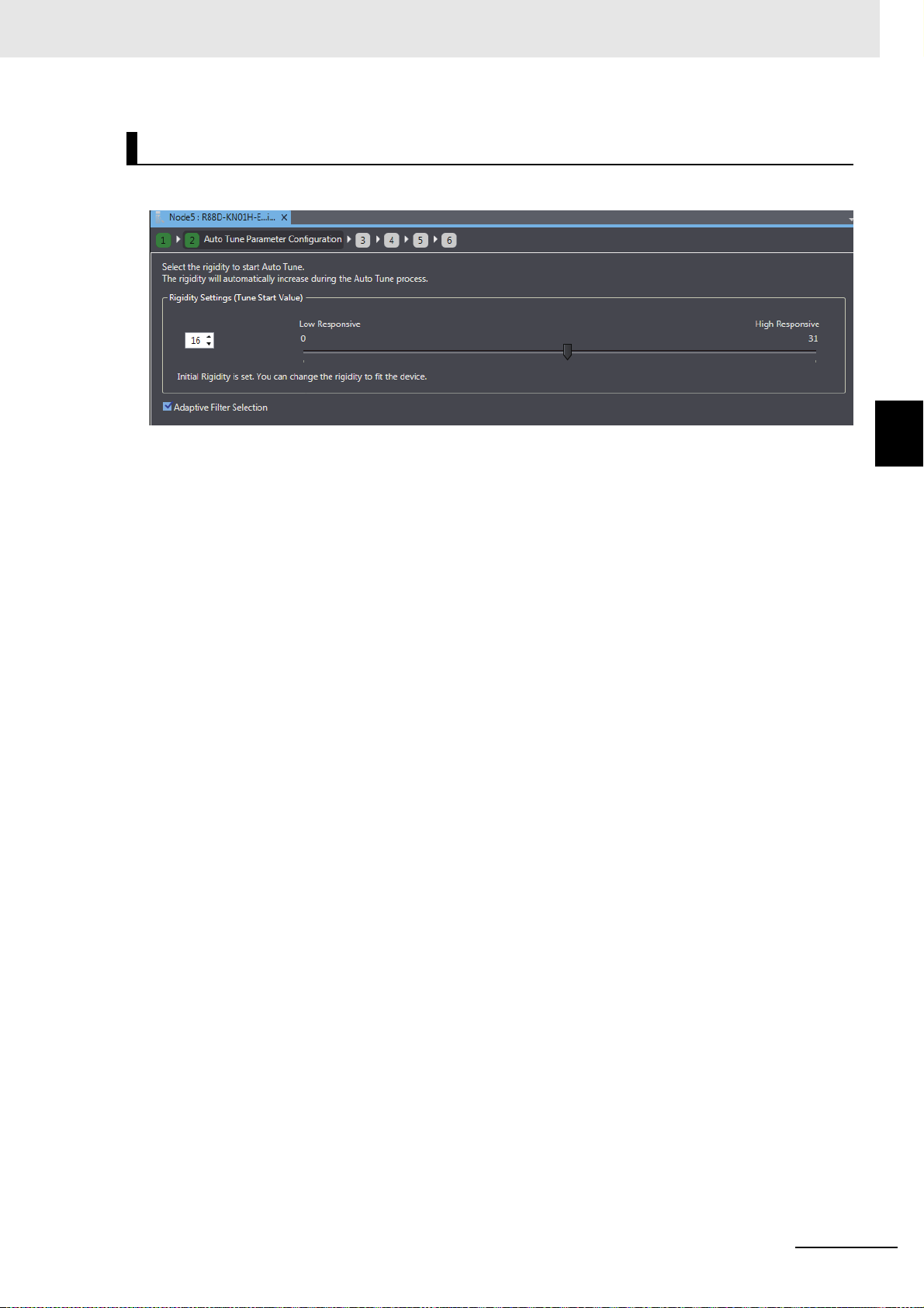
3 Basic Servo Drive Operations
Step 2: Auto Tune Parameter Configuration
Make the settings to be applied when auto tuning is started.
3-2 Auto Tuning
3
Setting the Default Rigidity
• Based on the machine configuration selected in Step 1, the default value at tuning start is automatically set.
• Normally, you don't have to change it, but you can set the value within the range from 0 to 31
cording to the device characteristics.
ac
• The rigidity value is automatically increased during
the Auto Tuning process in Step 3.
3-2-2 Auto Tuning for G5 Series
Setting the Adaptive Notch Filter
• Select whether the adaptive notch filter function is enabled or disabled by the Adaptive Filter
Selection check box.
Note Refer to the G5-series AC Servomotors and Servo Drives User’s Manual (with Built-in EtherCAT® Com-
munications) (Cat
EtherCAT® Communications) (Cat. No. I577) for details of the relationship between rigidity value and
parameter values and the adaptive notch filters.
After making the settings, click the Next button to go to the next step.
. No. I576) and the G5-series Linear Motors/Servo Drives User’s Manual (with Built-in
Sysmac Studio Drive Functions Operation Manual (I589)
3 - 13
Page 68

3 Basic Servo Drive Operations
Step 3: Behavior Configuration
Set the criteria for performing and finishing auto tuning.
Setting Auto Tuning Conditions
In the Auto Tune Configuration area, set the number of tuning iterations and duration of a tuning
iteration.
Selecting the Motion Profile Generator
You need to actually run the motor to execute auto tuning. Select whether the Motion Controller or
Sysmac Studio sends the operation commands to the motor.
• The Motion Controller will perform the motion profile
lect the tuning start trigger from
Se
the control mode of the device.
• Sysmac Studio (not the Motion Controller) w
Set the step distance, step jog speed, and accelera
tion status of the device.
With position instruction or With speed instruction according to
ill perform a Cyclic Step
tion/deceleration time according to the opera-
Setting the Criteria for Finishing Auto Tuning
As the auto tuning completion criteria, set the stabilization time, overshoot level, torque vibration
level, and position window according to the operation status of the device.
xt
After making the settings, click the Ne
button to go to the next step.
3 - 14
Sysmac Studio Drive Functions Operation Manual (I589)
Page 69
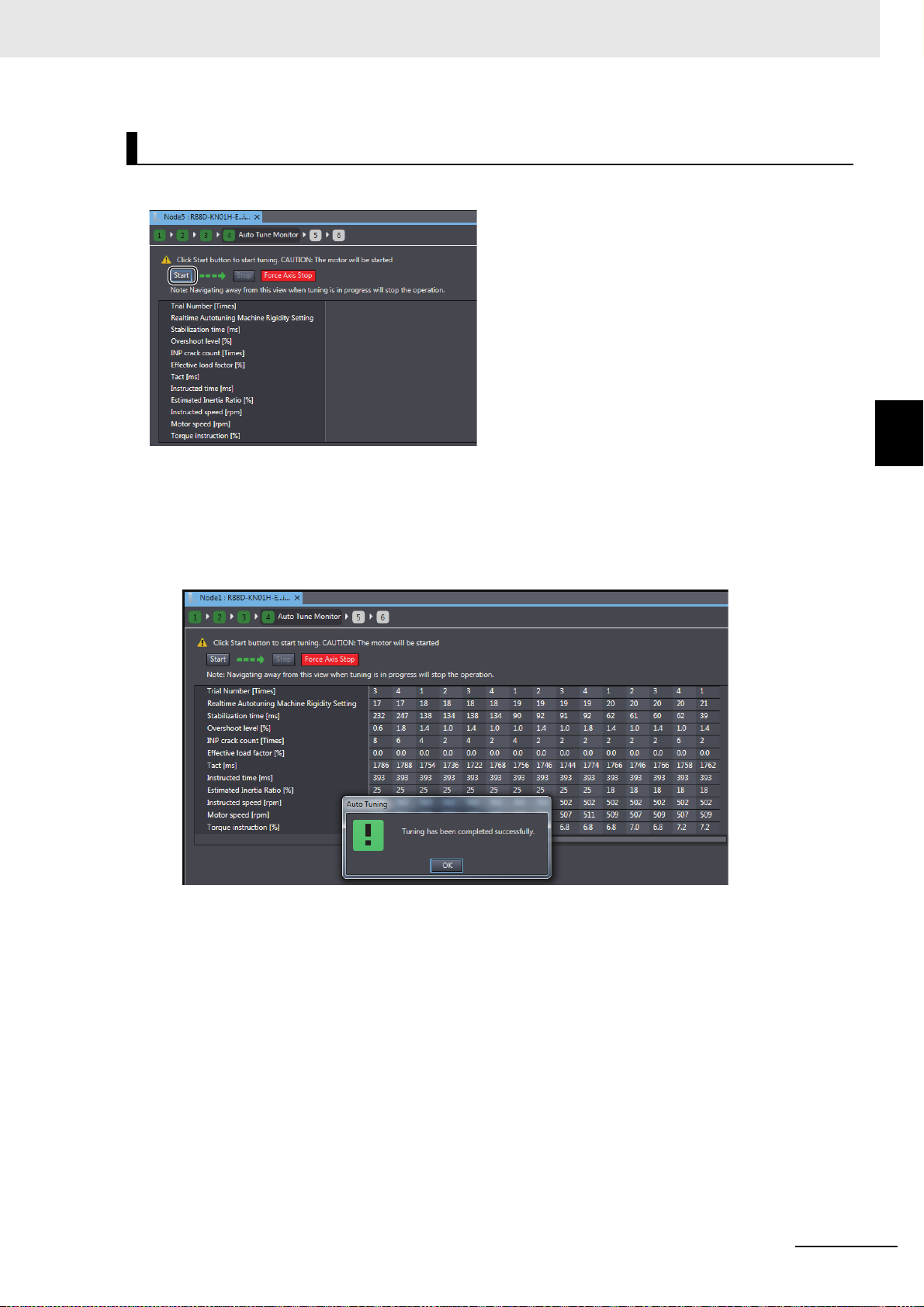
3 Basic Servo Drive Operations
Step 4: Auto Tune Monitor
Start execution of auto tuning.
3-2 Auto Tuning
3
Starting the Tuning
Click the Start button to start auto tuning.
When the completion criteria are satisfied or motor vibr
auto tuning will be stopped.
• Message displayed when Auto Tuning is Complete
Stopping the Tuning
3-2-2 Auto Tuning for G5 Series
ation is detected during the tuning process,
When you want to stop the tuning before completion, click the Stop button. The motor will be
stopped and the Drive will enter the Servo OFF state.
Forcibly Stopping the Tuning
Click the Force Axis Stop button to forcibly stop the auto tuning. The motor will be stopped and the
Drive will enter the Servo OFF state.
After making the settings, click the Next
Sysmac Studio Drive Functions Operation Manual (I589)
button to
go to the next step.
3 - 15
Page 70
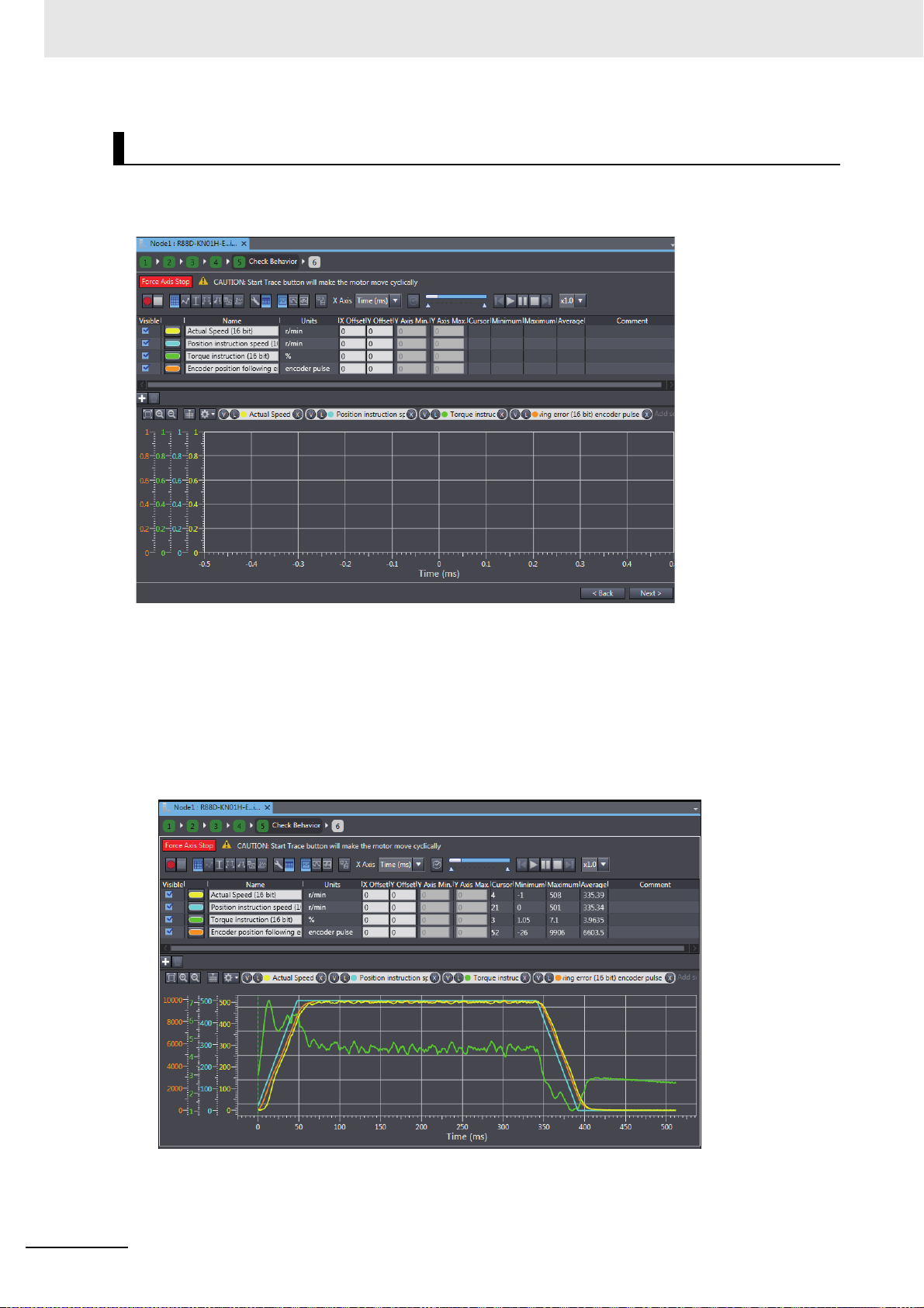
3 Basic Servo Drive Operations
Step 5: Check Behavior
Check the tuning results of the previous step using the data trace function.
Refer to 3-6 Data Tracing on
page 3-24 for details of the data trace function.
Data Trace Settings
By default the most frequently used parameters (actual speed, position instruction speed, torque
instruction, and encoder position following error) are registered to check the motor response. Like
the standard data trace function, you can add and delete the trace items as necessary.
Starting Data Tracing
When you click the start button, data tracing will be started. When it is completed, the results will be
displayed in the graph area.
3 - 16
After confirmation, click the Next
button to go to the next step.
Sysmac Studio Drive Functions Operation Manual (I589)
Page 71
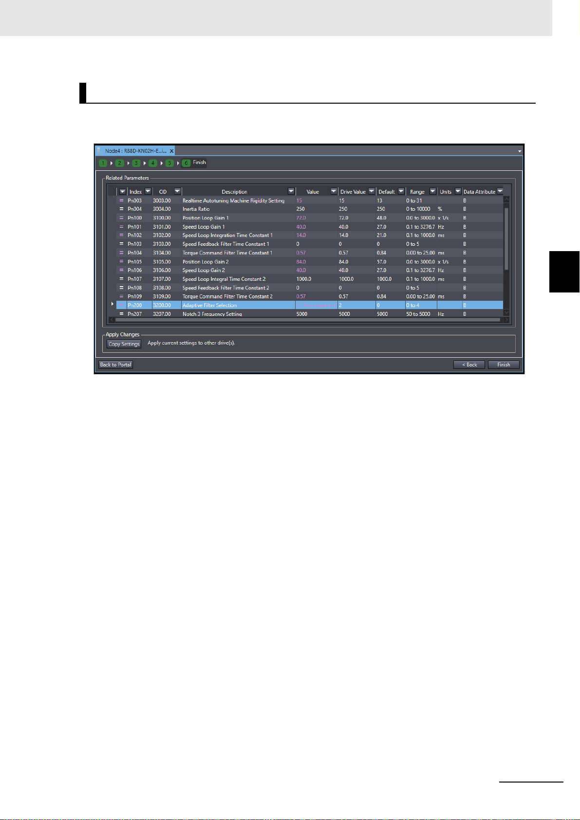
3 Basic Servo Drive Operations
Step 6: Finish
The auto tuning results are displayed in the form of parameter list. The parameters changed by auto
tuning are highlighted in purple.
3-2 Auto Tuning
3
3-2-2 Auto Tuning for G5 Series
Step 6-1: Copying the Settings
Click the Copy Settings button to copy the related parameters to other Drives. Refer to 3-1-1 Displaying and Editing Drive Parameters on
After confirmation, click the Finish b
utton to close the Auto Tuning wizard.
page 3-2 for details.
Sysmac Studio Drive Functions Operation Manual (I589)
3 - 17
Page 72

3 Basic Servo Drive Operations
Precautions for Safe Use
Precautions for Correct Use
3-3 Test Run
This section describes how to perform jogging and other test run operations to check motor operations
such as its rotation direction.
• Confirm the axis number carefully before you perform a test run.
• A test run operation involves motor operation. Refer to the operation manual before you execute a test run. Be particularly careful of the following points.
• Confirm safety around all moving parts.
• When you push the start button, the motor begins actual oper
Begin the motor operation only when you are absolutely sure there is no danger if you start
the motor.
• Always have an external emergen
• Sometimes you may be unable to stop the motor from your computer. Install an external
emer
gency stop device so that you can stop the motor immediately if needed.
• Only operate the motor when you can clearly conf
react quickly in the case of any danger that may arise due to operation of the motor.
• When you perform a test run via an NJ/NX/NY-series, Programmable Multi-Axis Controller
or CJ1WEtherCAT communications.
• A communications error will occur if you at
communications. Always establish EtherCAT communications first.
• When operation is performed, such data as a travel di
unit conversion settings for the axes assigned on the project file is displayed. Before performing operation, carefully check safety
units.
• Precautions during Test Run Operation
• During test run execution, only Sysmac Studio h
mands from motion control instructions are ignored.
• Make sure that you are operating the correct axis.
NC8 Position Controller, perform the test run op
ation at the specified velocity.
cy stop device available.
irm the motor operation so that you can
erations after establishing
tempt to begin operations without EtherCAT
stance and velocity calculated from the
by using units of drive measurement such as command
as any control of the operation. Any com-
• Before you start a test run, make sure that the operation parameters are set correctly.
• If you transfer the axis parameters or slave parameters to the slave during a test run from
another copy of Sysmac Studio, the test run will end and the axes will stop. This also applies
if the parameters are transferred from Sysmac Studio running on a different computer.
3 - 18
Sysmac Studio Drive Functions Operation Manual (I589)
Page 73

Starting a Test Run
Right-click the Drive and select Test Run from the menu.
3 Basic Servo Drive Operations
3-3 Test Run
3
Sysmac Studio Drive Functions Operation Manual (I589)
3 - 19
Page 74

3 Basic Servo Drive Operations
Test Run Operation Settings (only for 1S Series)
To execute the test run operation safely, preset the operating range limits for the motor.
• Enabling/Disabling the Operating Range Limits
Select Do not use or Use for
• Setting the Upper and Lower Limits of the Operating Range
To set the upper limit and lowe
Set maximum position, and Set minimum position buttons). You cannot directly enter values
in the fields.
• Operating Range Limit Settings
Item Description
Actual maximum position and Actual minimum position
Upper Limit and Lower Limit The upper and lower limits of the current
• How to Apply the Current Position to Upper or Lower Limit
Click the Set ac
tual position button to apply the actual current position displayed in the Test Run
area (enclosed in the green box) to the upper or lower limit. Then, the value is set for the upper or
lower limit as shown below.
the Operating Range Limit setting.
r limit values, click the setting buttons (i.e., Set actual position,
Actual maximum and minimum positions of
the currently running motor are displayed.
(Unit: Pulse)
ing range are displayed. (Unit: Pulse)
operat
• How to Apply the Maximum or Minimum Position to the Upper or Lower Limit
Click the Set maximum position or
Set minimum position bu
tton on the extreme right of the figure to apply the maximum or minimum position during the operation to the upper or lower limit,
respectively.
3 - 20
Sysmac Studio Drive Functions Operation Manual (I589)
Page 75
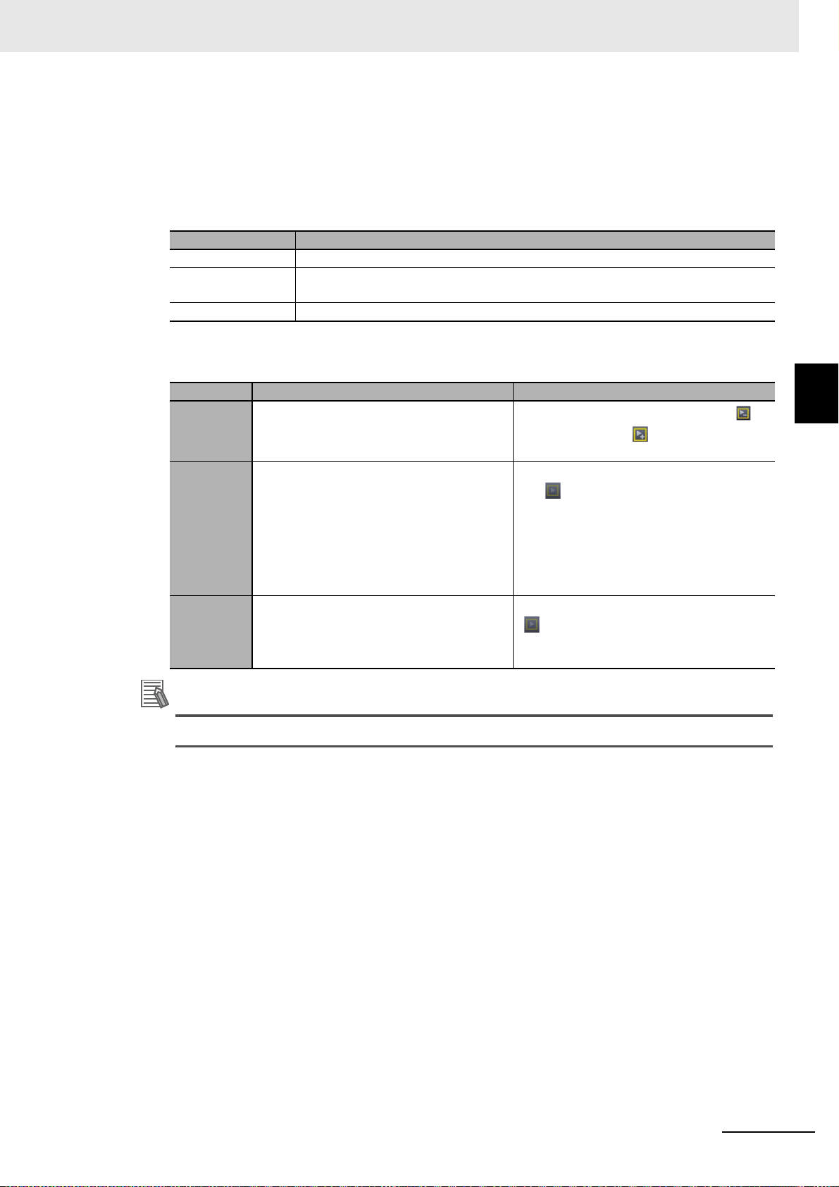
3 Basic Servo Drive Operations
Additional Information
Executing a Test Run
•Servo ON
Click the Servo ON but
• Starting the Operation
In the test run, the following operations can be commanded.
Operation Description
Jogging Speed-specified commands are executed.
Step Positioning with trapezoidal acceleration/deceler
Z-Phase Search The Z-phase search is executed.
Select one of the operation patterns by clicking a tab in the Test Run area. Then, set the operation parameters and click the Forward or Reverse button to execute the test run.
Tab Settings Operation
• Target Speed
Jogging
Step
Z-Phase
Search
• Acceleration/Deceleration Time
• Target Speed
• Acceleration/Deceleration Time
• Step Distance
• Cycle steps (Forward > Reverse, Reverse
> F
• Number of Cycles
• Dwell Time
• Target Speed The Z-phase search is started by clicking the
ton to enter the Servo ON status in order to start a test run.
ation is repeated for the specified
number of cycles.
The motor will run while the Forward ( )
button or Reverse ( ) button is held
down.
The step operation will be started by clicking
th
e
button.
orward, Forward, or Reverse)
button. The operation is automatically
stopped when Z-phase of the encoder is
detected.
3-3 Test Run
3
If the motor does not run, check the Motor Stop Cause status lamps.
Checking the Operating Status of the Motor
The current position and current motor speed are displayed in the Drive Status of the Test Run
area.
Checking the Motor Status
• Motor Stop Causes
Lamps are provided to show motor stop causes. A green lamp indicates an active cause.
• Current Alarms and How to Reset
The alarms listed here have been activated for the Drive
Reset Alarm button.
. The alarms can be reset by clicking the
Sysmac Studio Drive Functions Operation Manual (I589)
3 - 21
Page 76

3 Basic Servo Drive Operations
3-4 Status Monitor
The Status Monitor displays a list of objects for monitoring the Drive. Check the present values of the
objects.
Starting the Status Monitor
Right-click the Drive and select Status Monitor from the menu.
Selecting the Target Objects to Monitor
Select the check boxes for the objects to be monitored. The latest values of the parameters for the
selected objects are transferred from the Drive and displayed in the monitor.
Displaying the Present Values of the Objects
The latest values of the parameters in the Drive are displayed. When a value is updated, it is displayed in purple for one second.
3 - 22
Sysmac Studio Drive Functions Operation Manual (I589)
Page 77

3-5 Troubleshooting
Use the troubleshooting function to check the current errors related to the Drive and the event log
stored in the Drive.
3 Basic Servo Drive Operations
Starting the Troubleshooting
Right-click the Drive and select Troubleshooting from the menu. The current error information on
the Drive will be displayed.
Checking the Drive Errors
Click the Drive Errors ( ) button. The current errors related to the Drive are displayed. Check the
level, event name, event code, error code, and details of the event code.
• Click the Display Swit
Action and correction.
• Click the Reset All b
ch button to switch the view between Details/Attached information and
utton to reset the errors.
3-5 Troubleshooting
3
Checking the Drive Event Log
Click the Drive Event Log ( ) button. The event log (i.e., history) of the Drive is displayed. Check
the entry (log number), date and time, level, ev
• Filter the displayed items by selecting the desired items in the Displayed Information and
areas.
Sysmac Studio Drive Functions Operation Manual (I589)
ent name, event code, and detailed error code.
Level
3 - 23
Page 78

3 Basic Servo Drive Operations
Precautions for Correct Use
Additional Information
(a)
(b)
(c)
(d)
3-6 Data Tracing
Use data tracing function to sample and display specified drive parameters at a fixed interval.
Executing a Data Trace
• Right-click the Data Trace Settings under the trace-target Drive in the Multiview Explorer and
select Add - Data Trace from the menu.
Sysmac Studio provides two data tracing functions, one is for Drives described in this section
and the other is for Controllers. Refer to the Sysmac Studio Version 1 Operation Manual (Cat.
No. W504) for the data tracing function for Controllers.
• Double-click DataTrace0 that was created by the above operation.
More than one data trace can be added for each Drive.
• The following Data Trace tab page is displayed.
(a) Toolbar Buttons to start and stop tracing and display various items are displayed.
(b) Trace setting area Set the trace conditions.
(c) Trace target area Specify the trace targets.
(d) Graph area Graphs of trace results are displayed. The
3 - 24
The tab page consists of the following areas.
Item Description
upper part displays the analog values
and the lower part displays the digital values.
Sysmac Studio Drive Functions Operation Manual (I589)
Page 79

Setting Data Trace Conditions
Additional Information
If an invalid value is set, the field is highlighted in red.
When the mouse cursor is placed over the field, the valid
setting range is displayed.
3 Basic Servo Drive Operations
Set the data trace conditions. ((b) Trace setting area)
Item Description Settings
Trace Type Select the trace type from the two
options on the right.
Sampling
Interval
Select the sampling interval from
the
two options on the right.
Interval Enter the sampling interval in µs. • Enter a multiple of the Drive's minimum cycle in the
Total Trace
Time
Enter the trace time from start to
end in ms.
• Single: Data tracing is executed only once.
• Cyclic: Data tracing is repeatedly executed according
to the same settings. After loading the trace data,
Sysmac Studio automatically waits for the next trigger
to restart the tracing.
• Drive cycle: The minimum operating cycle of the Drive
is applied. (Example: 0.25 ms for G5 Series and
0.125 ms for 1S Series)
• Time: The time that you enter in the Inter
val fie
ld is
set as the sampling interval.
Interval field.
Minim
um cycle of 1S-series Servo Drives: 125 µs
Minimum cycle of G5-series Servo Drives: 250 µs
• The value of To
Trace Time can be changed only
tal
for 1S Series. The total trace time varies by the total
data size of sampling
*1
.
3-6 Data Tracing
3
Post-trigger
Data Ratio
Enable Trigger Condition
t the ratio of data to be sampled
Se
be
fore and after the specified trigger conditions are satisfied in percentage.
Set the trigger conditions for starting the sampling in the data trace.
• Enter the percentage of post-trigge
r data or move the
slider to set the desired value.
• None: Sampling is started at the same time as the
star
t of data tracing.
• Trigger 1: Sampling is started according to the condition set as Trigger 1.
• Trigger 2: Sampling is started according to the condition set as Trigger 2.
• Trigger 1 and Trigger 2
Sampling is started when the conditions set as Trigger 1 and Trigger 2 are satisfied at the same time.
• Trigger 1 or Trigger 2
Data tracing is started when either of the conditions
set a
Trigger 1 or Trigger 2 is satisfied.
s
Sysmac Studio Drive Functions Operation Manual (I589)
3 - 25
Page 80

3 Basic Servo Drive Operations
Item Description Settings
Trigger 1/
Trigger 2
*1. Data size of each sampled data is displayed at the end of the data in the data trace setting area. (Example:
Position Command - Motor Velocity (16 bit))
Set a trigger condition for saving
the sampled data.
Set only the triggers that you
selected
as a trace condition.
• Entering a parameter
Enter the data to be used as a trigger. Candidates will
be
displayed by pressing the Ctrl key and space key
at the same time when the field is empty.
• Comparison operator
Select a comparison operator from the drop-down list.
G5 Series: =, ≠, <, >,
1S Series: =, ≠, ≤, ≥, <, >, Risin
including level), and Falling (Including level/Not
including level)
• Filter settings
When setting an analog value as a trigger condition,
you
can prevent wrong trigger detection caused by
chattering by calculating the moving average of the
present value and past values using the filtering function.
(You can specify up to last 8 data items for G5 Series
an
16 data items for 1S Series.)
d last
sing, and Falling
Ri
g (Including level/Not
3 - 26
Sysmac Studio Drive Functions Operation Manual (I589)
Page 81

3 Basic Servo Drive Operations
Additional Information
Additional Information
Precautions for Correct Use
Setting the Data to Sample
Set the sampling target data of the data trace. ((c) Trace target area).
1 Adding/Deleting Data to Sample
• Add: Click the button. A row is added at the bottom of the table.
• Delete: Select the row to delete and click the button.
The four frequently used parameters are pre-registered by default.
2 Specifying Data to Sample
Enter the name of data to sample in
Candidates will be displayed by pressing the Ctrl key and space key at the same time in the
Name field when it is empty.
the Name field.
3-6 Data Tracing
3
As sampling data, up to six data items can be specified for 1S Series regardless of the data
size. For G5 series, up to four data items can be specified (i.e., up to 64 bits in total when only
16-bit data items are specified).
Setting the Details of Data to Sample
The following items can be displayed and set in the trace target area (c) as details of each data item
to sample.
Column Description Edit
Visible Select whether to show or hide the item. Possible
Line Color Select a graph color. Possible
Device Name Select the device name of the EtherCAT slave. (only for 1S Series) Possible
Name The name of the data to sample is displayed. Select the name from the can-
didates.
layed
Units The unit of the data to sample is disp
X Offset The offset of the X axis in the graph is displayed. Set the offset. Possible
Y Offset The offset of the Y axis in the graph is displayed. Set the offset. Possible
Y Axis Min. The minimum value of the Y axis in the graph is displayed. Not possible
Y Axis Max. The maximum value of the Y axis in the graph is displayed. Not possible
Cursor The cursor values at the time the range cursors are enabled are displayed. Not possible
Minimum The minimum value of the sampled data is displayed. Not possible
Maximum The maximum value of the sampled data is displayed. Not possible
Average The average value of the sampled data is displayed. Not possible
Comment The index and subindex of the sampled data are displayed. Not possible
. Not possible
Possible
Starting/Ending a Data Trace
• Starting a Data Trace
Click the button in the Toolbar.
• Ending a Data Trace
Sysmac Studio Drive Functions Operation Manual (I589)
3 - 27
Page 82

3 Basic Servo Drive Operations
(a)
(b)
(c)
(d)
(e)
Data tracing automatically finishes when it is completed according to a specified condition. To finish the tracing before completion, click the button.
Checking Data Trace Results
• Checking the Trace Results with a Graph
The traced data are displayed in the graph area (d).
Item Description
A. X axis (ms) The time is displayed always in ms.
B. Y axis The values of each data trace target a
C. Graph tools Buttons to zoom in and out, fit to the pane width, d
and manage Y Axis scales are displayed.
D. Y axis setting area The data trace targets assigned to the Y axis are displayed. Specify the display
area of each scale for Y axis.
E. Graph The data trace results are displayed.
re displayed individually.
isplay the cursor on the graph,
• Registering Multiple Scales for Y Axis (Multi-scale Y Axis Setting)
The graph area consists of the following items.
More than one sampled data item can be displayed with diffe
rent scales by registering the data as
scales for Y axis.
• Registering a scale manually
Click the Click to add
Enter a data trace target. Candidates will be displayed by press
scale, or drag from table.
ing the Ctrl key and space
key in the entry field when it is empty.
3 - 28
• Dragging from the trace target data area.
Click and drag a row for the item that you want to trace and drop it
onto the Click to add scale,
or drag from table.
• Deregistering a scale.
To deregister a scale from the Y axis, click the button in the Y axis settings area.
• Selecting a display area.
To switch the side to disp
L button: Displays the scale on the left sid
R button: Displays the scale on the right side of the graph area
lay each scale, click the or button in the Y axis setting area.
e of the graph area (default)
Sysmac Studio Drive Functions Operation Manual (I589)
Page 83

3 Basic Servo Drive Operations
Additional Information
• Using Graph Tools
• Zoom In and Zoom Out
To zoom in and zoom out the graph area, click the buttons or turn the scroll wheel of
the mouse.
• Zoom to Fit
All graphs are automatically adjusted to fit in the current graph area. Click
Only the sampled data with the scale for Y axis registered are subject to the auto adjustment.
• Displaying a Cursor
To display the cursor to show the present value, click the button.
• Managing Y Axis Scales
Click the button to operate with Y axis scales.
Open... : Restor
Save... : Saves current scale settings.
Ass
ign all signals: Reg
Unassign all signals: Deregisters all scales.
Group by
es previously saved scale settings.
isters all signals as scales.
unit: All sign
als with the same unit type are registered into the same scale.
the button.
3-6 Data Tracing
3
Sysmac Studio Drive Functions Operation Manual (I589)
3 - 29
Page 84

3 Basic Servo Drive Operations
Switching the View in the Graph Area
To select whether to show or hide each chart in the graph area, click the following buttons in the
Toolbar.
Icon Tooltip Description
Show Configuration Displays the trace settings.
Show Data Table Displays the trace targets.
Show Analog Chart Displays the analog chart in the graph area.
Show Digital Chart Displays the digital chart in the graph area.
Show Digital On Ana-
Displays the analog and digital charts in the same graph area.
log Chart
Using the Convenient Functions for the Graph Area
Some other convenient functions are provided for the graph area. Use the functions by clicking the
following buttons in the Toolbar.
Icon Tooltip Description
Transfer Parameters
from Drive after Trace
Open Properties Displays the Poperties pane.
Switch Layout Changes the display position of the trace ta
Save as History Saves the displayed graph data as history.
Show History Displays the graph data saved as history.
Show Grid Displays a grid in the graph area.
Show Markers Highlights sampling points in the graph area.
Uploads the trace results and settings from the Drive. Normally,
this is automatically executed when the trace is completed. Also,
you can manually upload them by clicking this button.
to the left of the graphs.
table to above or
rget
3 - 30
Show Cursor Displays a cursor to check the value of the parameter selected in
the graph.
The cursor can be moved right and left with a mouse.
Show Range Cursors Displays cursors to see the difference between specified two
points.
Make
Range Cursor
Fixed Width
Fixes the distance between two cursors when the range cursors
are displaye
d.
Show Legends Displays legends in the graph area.
Independent Y Axis
Mode
Uses a common scale for Y axis in the graph area. When a data
item is selected in the trace data table, the item's scale is used as
the common scale for the Y axis.
When the independent Y axis mode is enabled, the current
multi-scale
settings for the Y axis are cleared.
Sysmac Studio Drive Functions Operation Manual (I589)
Page 85

3 Basic Servo Drive Operations
Additional Information
Using Data Trace Properties
In the Properties pane, check the configuration of the traced data, trace target drive, and parameters
at the time of data trace execution. Also, the parameters at the time of tracing can be applied to the
project. To open the Properties pane, click the in the Toolbar.
•Comment
Enter a comment for the data trace.
• Configuration
The interval and total trace time set for the data trace are displayed.
• Parameters
A list of the parameters set in the Servo Drive at the tim
Clicking the Update Project button transfers the current parameter values from the Drive to the
project.
When multi-drive data tracing is executed, parameters of up to four nodes are displayed.
e of data trace execution is displayed.
3-6 Data Tracing
3
Saving Data Trace Results to the Project
After data tracing, you can save the data to a project. Data is saved on a data trace basis.
• Opening the saved trace data
Open a Sysmac Studio project and double
ing message is displayed. Click the Yes butt
-click a data trace in the Multiview Explorer. The followon.
Sysmac Studio Drive Functions Operation Manual (I589)
3 - 31
Page 86

3 Basic Servo Drive Operations
Precautions for Correct Use
Precautions for Correct Use
Exporting/Importing Data Trace Results
• Export
The settings and data of each data trace are exported into a c
Toolbar and specify a file.
•Import
The csv files that were previously exported are imp
according to your purpose.
(1) Superimposing a data trace graph
The trace settings and sampled data are superimposed on the current data trace. You can
display the data
1) Open the original data trace on which the data should be superimposed.
2) Click the button and specify the exported file.
• Only the files that were output by the above-mentioned export function can be imported.
• The trace conditions are not imported.
• The imported trace settings cannot be re-edited. They
shown below.
with the current data trace results.
orted. Use the following two procedures
sv file. Click the button in the
are grayed out in the edit pane as
(2) Reusing the Data Trace Settings
The trace conditions, trace settings, and sampled data of the exported data trace at the
time of data tracing are restored as is.
1) Delete all of the sampling target
2) Click the button and specify a file that was pr
• Only the files that were output by the above-mentioned export function can be imported.
• If one or more parameters are registered in the trace settings, the data is imported like the
superimposing function.
data in the trace settings.
eviously exported.
3 - 32
Sysmac Studio Drive Functions Operation Manual (I589)
Page 87

3 Basic Servo Drive Operations
Precautions for Correct Use
Precautions for Correct Use
Executing Data Tracing by Multiple Drives (only for 1S Series via NJ/NX/NY
controller)
You can synchronize the sampling start timing across multiple Drives to execute data tracing at the
same time. Enter the trace target device name in the Device Name column in the trace data area (c)
and set the data to sample. Other settings and execution procedures are the same as single data
tracing.
• Execute the data tracing from the view for the Drive for which you set the triggers.
• Enter the node name on the ECAT editor in the Device Name column. (The default node
names are an E followed by a sequential number starting from 001 like E001 and E002.)
• Data tracing can be performed for up to four Drives
ger. If five or more Drives are
ing message will be displayed.
set for the trace targets and data tracing is started, the follow-
including the device that detects the trig-
3-6 Data Tracing
3
• The sampling data between the Drives is not synchroni
longer than EtherCAT PDO communication cycle.
• If you change any data settings when a graph is displayed after data tracing is completed
and then export the data, the results will not be consistent with the settings in the exported
data.
• The exported CSV file of trace results is encoded in UTF-8 character codes.
• When you import a CSV file, specify the CSV file to which the Drive trac
exported.
• If the CSV file is edited after it was export
ed, it may not be possible to import it.
zed if you set the sampling interval
e results were
Sysmac Studio Drive Functions Operation Manual (I589)
3 - 33
Page 88

3 Basic Servo Drive Operations
3-7 Motors and Encoders
Set the motor's status display and encoders.
Open the Motor and Encoder Properties tab page
3-7-1 Motor Properties
Confirm the motor properties.
Displaying the Motor Properties
Click the Motor Properties ( ) button. When Sysmac Studio is online with the Drive, the follow-
Right-click the Drive and select Motor and Encoder from the menu.
ing properties of the connected motor are displayed.
Item Value
Motor ID Motor's model number
Serial Number Motor's serial number
Capacity Motor capacity
Speed Rated speed
Voltage Rated voltage
Encoder Encoder type
3 - 34
Sysmac Studio Drive Functions Operation Manual (I589)
Page 89

Precautions for Correct Use
Precautions for Safe Use
3-7-2 Encoder Properties
This section describes how to monitor the encoder status and initialize the encoder.
3 Basic Servo Drive Operations
Displaying the Encoder Properties
Click the Encoder Properties ( ) button. When Sysmac Studio is online with the Drive, the
encoder properties can be confirmed and the function
s for the properties can be executed.
Confirming the Encoder Status
Encoder status information is displayed in the Monitor area of the Encoder Properties tab page.
Setting up the Encoder
If an error occurred in the encoder when a motor with an absolute encoder was used, you need to
set up the encoder using the Operations function in the Encoder Properties tab page.
• Clearing the system.
Click the Clear s
• Resetting alarms
Click the Rese
A list of current alarms is displayed with their even
• Resetting the communications error count (only for 1S Series)
Click the Reset Communications Error Count bu
errors that occurred in the encoder.
• Resetting the motor replacement detection error (only for 1S Series)
Click the Rese
detection error.
ystem button to clear the multiple rotation data of the encoder.
t alarm button to clear the current alarms in the encoder.
t names and error codes.
tton to clear the number of communication
t Motor Replacement Detection error button to clear the motor replacement
3-7 Motors and Encoders
3
3-7-2 Encoder Properties
• For 1S Series, the following message is displayed when you execute the system clear operation. Click the Yes butto
using the Troubleshooting function of the Controller.
• For G5 Series, after executing the system clear oper
Troubleshooting function of the Controller or cycle the power supply to the Drive.
If the absolute encoder setting function is executed, the multiturn counter and encoder alarm
are reset in the absolute serial encoder. When the multiturn counter in the absolute encoder is
reset to 0, the previously defined machine system changes to a different coordinate system.
After the encoder is set normally, reset the zero point of the mechanical system.
n to restart the Drive. After restarting the Drive, reset the errors
ation, you need to reset errors using the
Sysmac Studio Drive Functions Operation Manual (I589)
3 - 35
Page 90
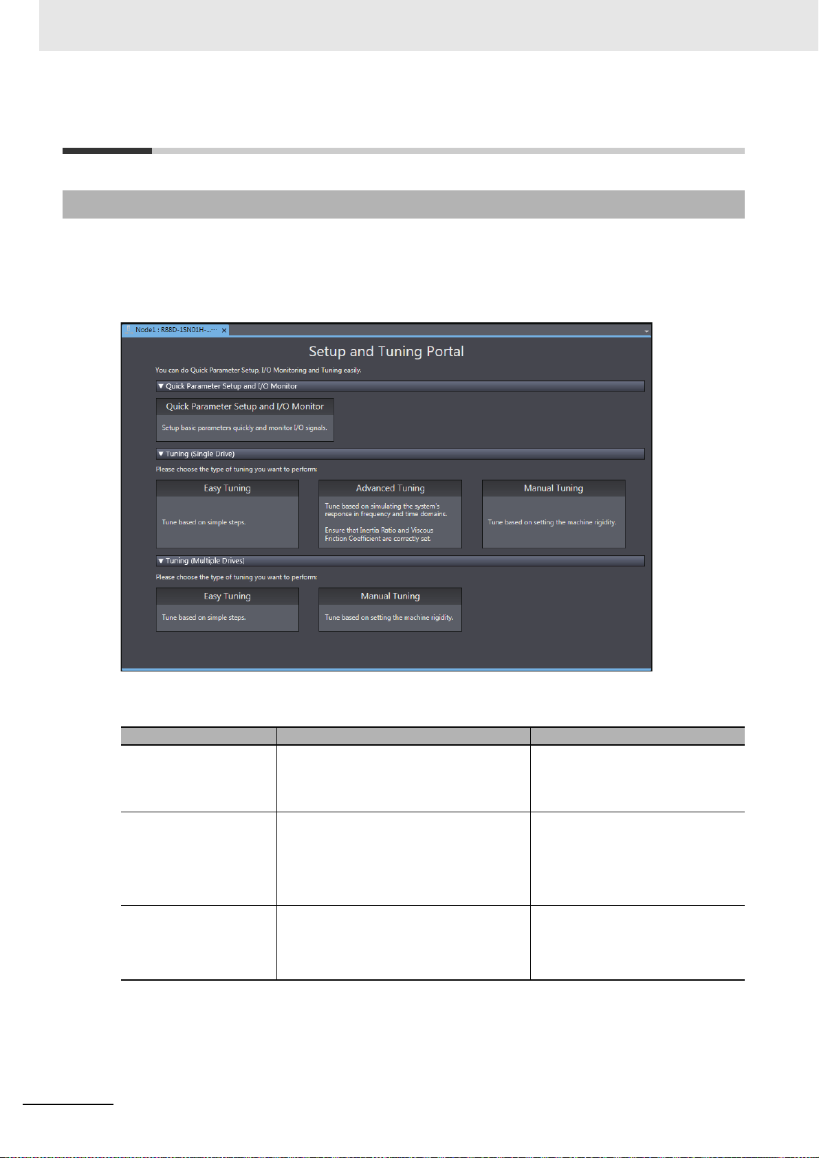
3 Basic Servo Drive Operations
3-8 Setup and Tuning Wizard
3-8-1 Overview
The Setup and Tuning wizard enables quick parameter setup and monitoring, access to the Test Run
features and a choice of tuning functions.
up an
Click the Drive and select Set
d Tuning from the menu.
The portal page of the Setup and Tuning wizard has the following buttons.
Button Function Connection type
Quick Parameter Setup
and I/O Moni
Tuning (Single Drive) The following three kinds of tuning methods
Tuning (Multiple Drives) The following two kinds of tuning methods
tor
You can set and transfer basic parameters
(mainly for assigning functions to external
I/O signals), monitor the I/O signals, and
perform a test run.
are provi
• Easy tuning
• Advanced tuning
• Manual tuning
are provided for mu
• Easy tuning
• Manual tuning
ded for si
ngle Drive.
ltiple Drives.
Any
Any
• EtherCAT connection via an
NJ/NX/NY-series CPU Unit
• EtherCAT connection via a Programmable Multi-Axis Controller
3 - 36
Sysmac Studio Drive Functions Operation Manual (I589)
Page 91

(a)
(b)
3-8-2 Quick Parameter Setup and I/O Monitor
Click the Quick Parameter Setup and I/O Monitor button.
In the Quick Parameter Setup and I/O Monitor tab page, set and transfer the parameters that are
ired for startup, monitor the I/O signals, and perform a test run.
requ
Step 1: Motor and Encoder Setting
When you use an absolute encoder, set up the encoder.
3 Basic Servo Drive Operations
3-8 Setup and Tuning Wizard
3
3-8-2 Quick Parameter Setup and I/O Monitor
No. Item Description
(a) Setting area Set up the absolute encoder. Then, make the setti
output signals.
(b) Test Run tab page Perform a test run, monitor the I/O signals, and forcibly change
the status
of the signals.
ngs of input and
Step 1-1: Selecting Whether or not an OMRON Controller is Connected
Select Use when you use an OMRON Controller. Otherwise, select Do not use.
When Use is selected
, recommended setting values for the OMRON Controller are applied.
Step 1-2: Selecting Usage of the Absolute Encoder
Select the usage of the absolute encoder connected to the Servo Drive.
1 Select one of the following options in the How to Use Absolute Encoder area.
• Use as absolute encoder
• Use as incremental encoder
• Use as absolute encoder but ignore multi-rotation counter overflow
2 Click the Transfer To Drive button to transfer the selected settings to the Drive. The transferred
settings are applied after the Drive is restarted. Restart the Drive according to the specified procedure.
Sysmac Studio Drive Functions Operation Manual (I589)
3 - 37
Page 92

3 Basic Servo Drive Operations
Step 1-3: Setting up the Absolute Encoder
To set up the absolute encoder, click the Launch Motor and Encoder view button. Refer to 3-7
Motors and Encoders on
page 3-34 for details.
Step 1-4: Selecting the Motor Rotation Direction and Transferring the Set-
tings
1 Select the motor's rotation direction for positive commands in the Motor Rotation area.
• CW (Clockwise)
• CCW (Counterclockwise)
2 When you transfer the selected settings to the Drive, click the Transfer To Drive button. The
transferred settings are applied after the Drive is restarted. Restart the Drive according to the
specified procedure.
Step 1-5: Performing a Test Run
Perform a test run to confirm that the correct motor rotation direction is set. Refer to 3-8-3 Test Run
and Function Status on page 3
-45 for details.
When all the settings and the transfer operation are completed, click the Next button
.
3 - 38
Sysmac Studio Drive Functions Operation Manual (I589)
Page 93

3 Basic Servo Drive Operations
Step 2: Input Signals Setting
Set the function assignment and monitor the current status of external inputs to the Drive.
3-8 Setup and Tuning Wizard
3
3-8-2 Quick Parameter Setup and I/O Monitor
Step 2-1: Setting the Function Assignment to External Inputs
In the Input Signals area, make the function assignment settings for external inputs.
1 Assign a function each to input terminals IN1 to IN8.
2 Set the signal active condition.
Low: Positive (NO), High: Negative (NC)
Step 2-2: Monitoring the Current Status of each External Input
Monitor the current status of each physical signal by checking the Physical signal status or terminal display.
Also, monitor the status of the func
Step 2-3: Returning to Factory Settings
Click the Return to Factory Setting button. Then, the input signals are reset to the factory settings.
Step 2-4: Transferring the Settings to the Drive and Restarting the Drive
When you transfer the selected settings to the Drive, click the Transfer To Drive button. The transferred settings are applied after restarting the Drive.
cedure.
Step 2-5: Checking the Wiring and Settings of the Input Terminals
tions assigned to each terminal in the Function Status tab page.
Restart the Drive according to the specified pro-
In the Function Status tab page, you can perform a test run to see if the wiring to the input terminals
and functions and signal active conditions of the input terminals are correct. Refer to 3-8-3 Test Run
and Function Status on
When all the settings and the transfer o
Sysmac Studio Drive Functions Operation Manual (I589)
page 3-45 for details.
peration are completed, click the Next button.
3 - 39
Page 94

3 Basic Servo Drive Operations
Step 3: Output Signals Setting
Set the function assignment and monitor the current status of external outputs from the Drive.
Step 3-1: Setting the Function Assignment to External Outputs
In the Output Signals area, make the function assignment settings for external outputs.
1 Assign an object (i.e., function) each to output terminals OUT1 to OUT3.
2 Set the signal active condition.
Low: Positive (NO), High: Negative
Step 3-2: Monitoring the Current Status of each External Output
Monitor the current status of each physical signal by checking the Physical signal status or terminal display.
Also, monitor the status of the functions assigned to
Step 3-3: Returning to Factory Settings
Click the Return to Factory Setting button. Then, the output signals are reset to the factory settings.
Step 3-4: Transferring the Settings to the Drive and Restarting the Drive
Click the Transfer To Drive button. Only the output signal settings are transferred to the Drive and
the Drive is restarted.
Step 3-5: Performing a Test Run
(NC)
each terminal in the Function Status tab page.
3 - 40
You can perform a test run to see if the functions and signal active conditions of the output terminals
are correct.
Sysmac Studio Drive Functions Operation Manual (I589)
Page 95

3 Basic Servo Drive Operations
Step 3-6: Checking the Wiring and Settings of the Output Terminals
In the Function Status tab page, you can perform a test run to see if the wiring to the output terminals and functions and signal active conditions of the output
forcibly turn ON and OFF the output terminals from Sysmac Studio. Refer to 3-8-3 Test Run and
Function Status on
page 3-45 for details.
terminals are correct. Also, you can
3-8 Setup and Tuning Wizard
Step 4: Finish
A list of parameter values set as the result of changes in previous steps is displayed.
3
3-8-2 Quick Parameter Setup and I/O Monitor
Step 4-1: Checking the Related Parameters
Check the setup results of the parameters.
Step 4-2: Copying the Settings
Click the Copy Settings button to copy the related parameters to other Drives. Refer to 3-1-1 Displaying and Editing Drive Parameters on
When the settings are completed, click the Finish butto
wizard will be displayed.
page 3-2 for details.
n. The portal page of the Setup and Tuning
Sysmac Studio Drive Functions Operation Manual (I589)
3 - 41
Page 96

3 Basic Servo Drive Operations
Objects Set by Quick Parameter Setup
The following parameters are set by the setup.
Index (hex)
3000 --- Basic Functions
4320 --- Main Circuit Power Supply
4510 --- Encoder
4630 --- Positive Drive Prohibition Input
4631 --- Negative Drive Prohibition Input
4632 --- External Latch Input 1
4633 --- External Latch Input 2
4634 --- Home Proximity Input
4635 --- Positive Torque Limit Input
4636 --- Negative Torque Limit Input
4637 --- Error Stop Input
4638 --- Monitor Input 1
4639 --- Monitor Input 2
463A --- Monitor Input 3
463B --- Monitor Input 4
463C --- Monitor Input 5
463D --- Monitor Input 6
Subindex
(hex)
Name
01 Motor Rotation Direction Selection
02 Phase Loss Detection Enable
01 Operation Selection when Using Absolute Encoder
01 Port Selection
02 Logic Selection
01 Port Selection
02 Logic Selection
01 Port Selection
02 Logic Selection
01 Port Selection
02 Logic Selection
01 Port Selection
02 Logic Selection
01 Port Selection
02 Logic Selection
01 Port Selection
02 Logic Selection
01 Port Selection
02 Logic Selection
01 Port Selection
02 Logic Selection
01 Port Selection
02 Logic Selection
01 Port Selection
02 Logic Selection
01 Port Selection
02 Logic Selection
01 Port Selection
02 Logic Selection
01 Port Selection
02 Logic Selection
3 - 42
Sysmac Studio Drive Functions Operation Manual (I589)
Page 97

3 Basic Servo Drive Operations
Index (hex)
463E --- Monitor Input 7
463F --- Monitor Input 8
4650 --- Error Output
4651 --- Servo Ready Output
4652 --- Positioning Completion Output 1
4653 --- Positioning Completion Output 2
4654 --- Velocity Attainment Detection Output
4655 --- Torque Limit Output
4656 --- Zero Speed Detection Output
4657 --- Velocity Conformity Output
4658 --- Warning Output 1
4659 --- Warning Output 2
465A --- Velocity Limiting Output
465B --- Error Clear Attribute Output
465C --- Remote Output 1
465D --- Remote Output 2
465E --- Remote Output 3
Subindex
(hex)
01 Port Selection
02 Logic Selection
01 Port Selection
02 Logic Selection
01 Port Selection
02 Logic Selection
01 Port Selection
02 Logic Selection
01 Port Selection
02 Logic Selection
01 Port Selection
02 Logic Selection
01 Port Selection
02 Logic Selection
01 Port Selection
02 Logic Selection
01 Port Selection
02 Logic Selection
01 Port Selection
02 Logic Selection
01 Port Selection
02 Logic Selection
01 Port Selection
02 Logic Selection
01 Port Selection
02 Logic Selection
01 Port Selection
02 Logic Selection
01 Port Selection
02 Logic Selection
01 Port Selection
02 Logic Selection
01 Port Selection
02
Logic Selection
Name
3-8 Setup and Tuning Wizard
3
3-8-2 Quick Parameter Setup and I/O Monitor
Sysmac Studio Drive Functions Operation Manual (I589)
3 - 43
Page 98

3 Basic Servo Drive Operations
Index (hex)
Subindex
(hex)
Name
465F --- Zone Notification Output 1
01 Port Selection
02 Logic Selection
4660 --- Zone Notification Output 2
01 Port Selection
02 Logic Selection
4661 --- Position Command Status Output
01 Port Selection
02 Logic Selection
4662 --- Distribution Completed Output
01 Port Selection
02 Logic Selection
4663 --- External Brake Interlock Relay Output
01
02
Port Selection
Logic Selection
*1
*1
*1. Revised in Servo Drive Unit Version 1.2 or later.
3 - 44
Sysmac Studio Drive Functions Operation Manual (I589)
Page 99

3-8-3 Test Run and Function Status
You can perform a test run, monitor I/O signals, and forcibly turn ON and OFF output signals. These
operations can be performed while the Drive is in Test Run mode.
Test Run
Perform a test run from the Test Run tab page.
1 Select Jogging or Step for Operation to set the operation pattern.
2 Run the motor while checking the values of Actual Current Position and Actual Current
Speed.
3 Basic Servo Drive Operations
3-8 Setup and Tuning Wizard
3
3-8-3 Test Run and Function Status
Step 1: Turning ON the Servo Drive
Click the Servo ON button to turn ON the Servo Drive.
Step 2: Jogging
1 Select Jogging for Operation.
2 Set the target speed and acceleration/deceleration time.
3 Click the Apply button.
4 Click and hold the button or the button. While you hold one of the buttons, jogging is per-
formed.
Sysmac Studio Drive Functions Operation Manual (I589)
3 - 45
Page 100

3 Basic Servo Drive Operations
Step 2: Stepping
1 Select Step for Operation.
2 Select the rotation direction from Forward > Reverse, Reverse > Forward, Forward, or Reverse.
3 Set the target speed, acceleration/deceleration time, step distance, number of cycles, and dwell
time.
4 Click the Apply button.
5 Click the button. The step operation is started.
Step 3: Checking the Current Operation
In the Motion area, the actual current position and actual current speed are displayed.
Step 4: Stopping the Motor
When you want to stop the motor during the step operation, click the button.
3 - 46
Sysmac Studio Drive Functions Operation Manual (I589)
 Loading...