

Omron Sysmac NY-, Sysmac NY512-1400, Sysmac NY512-1300, Sysmac NY532-1500, Sysmac NY532-1400 Installation Manual
...Page 1

Industrial PC Platform
-series
NY
Motion Control Instructions Reference Manual
NY532-1500
NY532-1400
NY532-1300
NY512-1500
NY512-1400
NY512-1300
W561-E1-05
Page 2

NOTE
1. All rights reserved. No part of this publication may be reproduced, stored in a retrieval system, or
transmitted, in any form, or by any means, mechanical, electronic, photocopying, recording, or
otherwise, without the prior written permission of OMRON.
2. No patent liability is assumed with respect to the use of the information contained herein.
Moreover
mation contained in this manual is subject to change without notice.
3. Every precaution has been taken in the preparation of this manual. Nevertheless, OMRON as-
sumes no responsibility for errors or omissions.
Neither is any liability assumed for damages resulting from the use of the information contained in
this publication.
, because OMRON is constantly striving to improve its high-quality products, the infor-
Trademarks
• Sysmac and SYSMAC are trademarks or registered trademarks of OMRON Corporation in Japan
and other countries for OMRON factory automation products.
• Microsoft, Windows, Excel, and V
crosoft Corporation in the United States and other countries.
• EtherCAT
GmbH, Germany.
®
is registered trademark and patented technology, licensed by Beckhoff Automation
isual Basic are either registered trademarks or trademarks of Mi-
• ODVA, CIP, CompoNet, DeviceNet, and EtherNet/IP are trademarks of ODVA.
• The SD and SDHC logos are trademarks of SD-3C, LLC.
• Intel and Intel Core are trademarks of Intel Corporation in the U.S. and / or other countries.
Other company names and product names in this document are the trademarks or registered trade-
marks of their respective companies.
Copyrights
• Microsoft product screen shots reprinted with permission from Microsoft Corporation.
• This product incorporates certain third party software. The license and copyright information associ-
ated with this software is available at
http://www.fa.omron.co.jp/nj_info_e/.
Page 3

Introduction
Thank you for purchasing an NY-series IPC Machine Controller Industrial Panel PC / Industrial Box
PC.
In this manual, the Industrial Panel PCs and Industrial Box PCs may be collectively referred to as “NY-
series Industrial PCs”. In this manual, the range of devices that are directly controlled by the Controller
functions embedded in the Real-Time OS in the NY-series Industrial PC may be expressed as the
Controller.
This manual describes the motion control instructions. Please be sure that you sufficiently understand
the operations and handling procedures, and use the Motion Control Function Module (abbreviated as
“MC Function Module”) correctly.
Use this manual together with user's manuals for the NY-series Controller.
When you have finished reading this manual, keep it in a safe location where it will be readily available
for future use.
Introduction
Intended Audience
This manual is intended for the following personnel, who must also have knowledge of electrical sys-
tems (an electrical engineer or the equivalent).
• Personnel in charge of introducing FA systems.
• Personnel in charge of designing FA systems.
• Personnel in charge of installing and maintaining FA systems.
• Personnel in charge of managing FA systems and facilities.
For programming, this manual is intended for personnel who understand the programming language
specifications in international standard IEC 61131-3 or Japanese standard JIS B 3503.
Applicable Products
This manual covers the following products.
• NY-series IPC Machine Controller Industrial Panel PC
• NY532-15££
• NY532-14££
• NY532-13££
• NY532-5400
• NY-series IPC Machine Controller Industrial Box PC
• NY512-15££
• NY512-14££
• NY512-13££
Part of the specifications and restrictions for the products may be given in other manuals.
Refer to Relevant Manuals on page 2 and Related Manuals on page 22.
NY-series Motion Control Instructions Reference Manual (W561)
1
Page 4
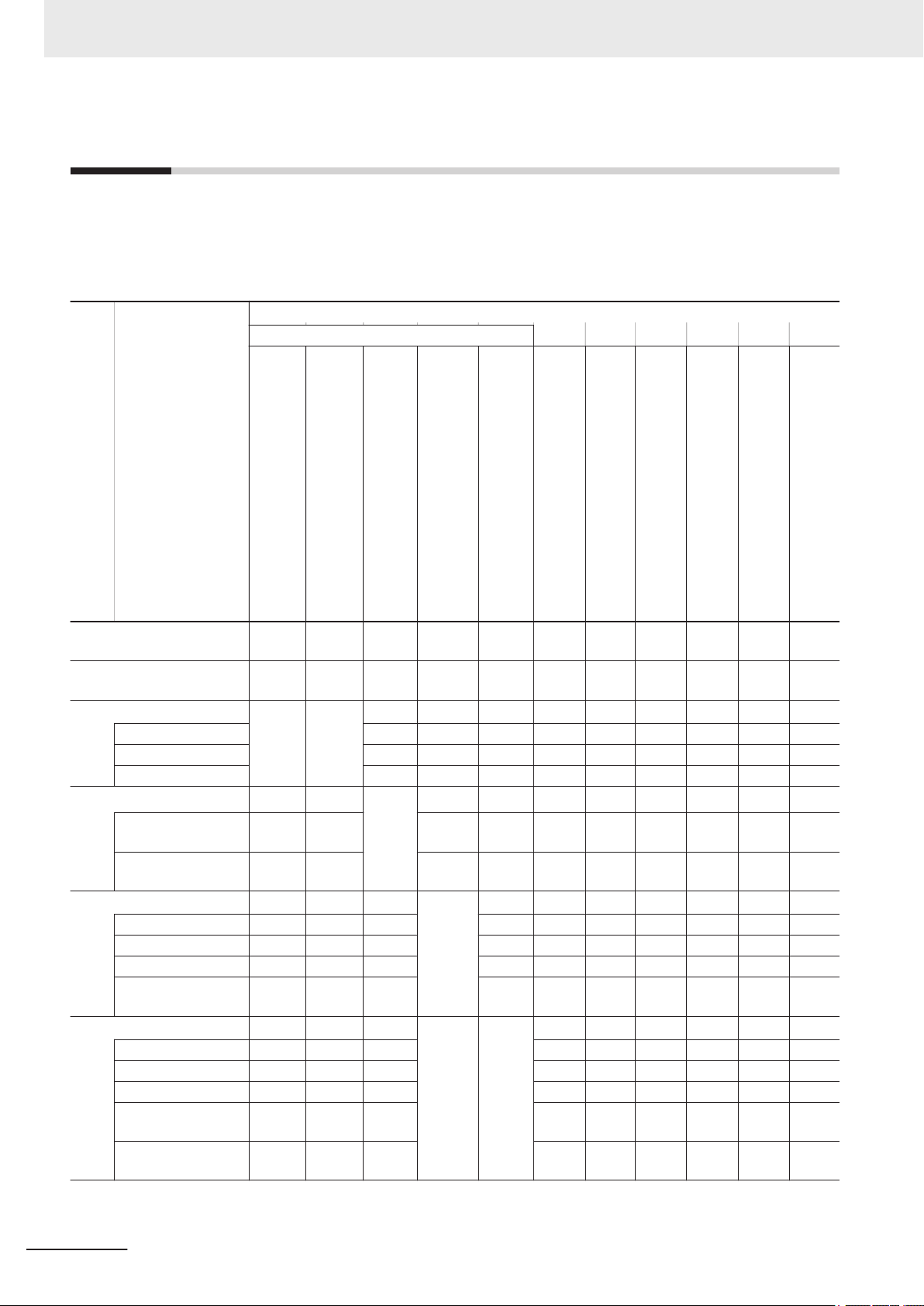
Relevant Manuals
Relevant Manuals
The following table provides the relevant manuals for the NY-series Controller. Read all of the manuals
that are relevant to your system configuration and application before you use the NY-series Controller.
Most operations are performed from the Sysmac Studio Automation Software. Refer to the Sysmac
Studio Version 1 Operation Manual (Cat. No. W504) for information on the Sysmac Studio.
NY-series IPC Machine Controller
Industrial Panel PC
Hardware User's Manual
Basic information
NY-series IPC Machine Controller
Industrial Box PC
Hardware User's Manual
Manual
NY-series
NY-series IPC Machine Controller
Industrial Panel PC / Industrial Box PC
Setup User's Manual
Industrial Panel PC / Industrial Box PC
Software User
Instructions Reference Manual
NY-series IPC Machine Controller
NY-series IPC Machine Controller
Industrial Panel PC / Industrial Box PC
Motion Control User's Manual
NY-series
Motion Control Instructions Reference Manual
NY-series IPC Machine Controller
Industrial Panel PC / Industrial Box PC
Built-in EtherCA
NY-series IPC Machine Controller
Industrial Panel PC / Industrial Box PC
Built-in EtherNet/IP Port User's Manual
NJ/NY-series NC Integrated Controller
User's Manual
NY-series
T
roubleshooting Manual
Purpose of use
Introduction to NY-series Panel PCs
Introduction to NY-series Box
PCs
Setting devices and hardware
Using motion control
Using EtherCAT
Using EtherNet/IP
Making setup
Software settings
Writing the user program
*1
Making the initial settings
Preparing to use Controllers
Using motion control
Using EtherCAT
Using EtherNet/IP
Using numerical control
Using motion control
Using EtherCAT
Using EtherNet/IP
Using numerical control
Programming error
processing
¡
¡ ¡
’s Manual
¡
¡
¡
¡
¡
¡ ¡
¡ ¡
T Port User’s Manual
¡
¡
¡
¡
¡
¡
¡
¡
¡
2
NY-series Motion Control Instructions Reference Manual (W561)
Page 5
NY-series IPC Machine Controller
Industrial Panel PC
Hardware User's Manual
Basic information
NY-series IPC Machine Controller
Industrial Box PC
Hardware User's Manual
NY-series IPC Machine Controller
Industrial Panel PC / Industrial Box PC
Setup User's Manual
Manual
NY-series
Instructions Reference Manual
NY-series IPC Machine Controller
Industrial Panel PC / Industrial Box PC
Software User
NY-series IPC Machine Controller
Industrial Panel PC / Industrial Box PC
Motion Control User's Manual
NY-series
Motion Control Instructions Reference Manual
Relevant Manuals
NY-series IPC Machine Controller
Industrial Panel PC / Industrial Box PC
Built-in EtherCA
NY-series IPC Machine Controller
Industrial Panel PC / Industrial Box PC
Built-in EtherNet/IP Port User's Manual
NJ/NY-series NC Integrated Controller
User's Manual
NY-series
T
roubleshooting Manual
’s Manual
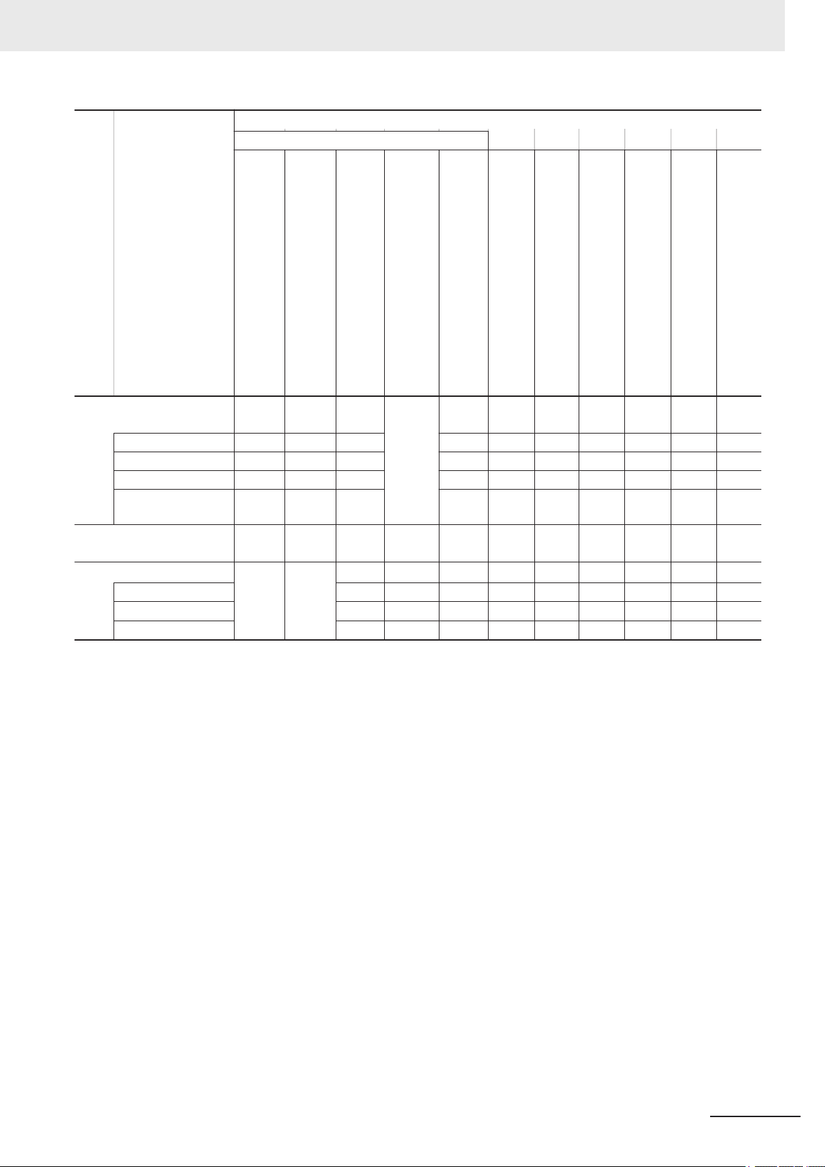
Purpose of use
Testing operation and debugging
Using motion control
Using EtherCAT
Using EtherNet/IP
Using numerical control
Learning about error manage-
ment and corrections
Maintenance
Using motion control
Using EtherCAT
Using EtherNet/IP
*1. Refer to the NY
the utilities on Windows.
*2. Refer to the NY-series Troubleshooting Manual (Cat. No. W564) for the error management concepts and an overview of the error
items.
*2
¡ ¡
-series Industrial Panel PC / Industrial Box PC Setup User’s Manual (Cat. No. W568) for how to set up and how to use
¡
¡
¡
T Port User’s Manual
¡
¡
¡
¡
¡
¡
NY-series Motion Control Instructions Reference Manual (W561)
3
Page 6
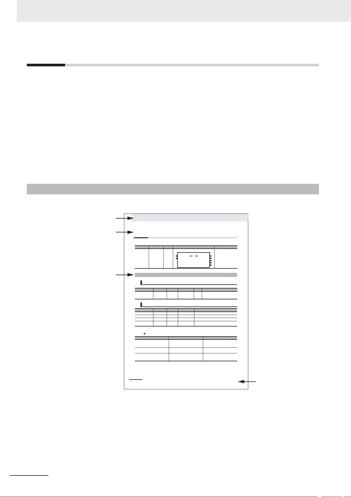
Manual name
Le
vel-1 section heading
3 Axis Command Instructions
3-2
NJ-series Motion Control Instructions Reference Manual (W508)
MC_Power
The MC_Power instruction makes a Servo Drive ready to operate.
* Refer to A-1 Error Codes.
Output Variable Update Timing
Instruction Name FB/FUN Graphic expression ST expression
MC_Power Power Servo FB MC_Power_instance (
Axis :=parameter,
Enable :=parameter,
Status =>parameter,
Busy =>parameter,
Error =>parameter,
ErrorID =>parameter
);
Variables
Input Variables
Name Meaning Data type Valid range Default Description
Enable Enable BOOL TRUE or FALSE FALSE The device is ready for operation when
Enable is TRUE, and not ready when it is
FALSE.
Output Variables
Name Meaning Data type Valid range Description
Status Servo ON BOOL TRUE or FALSE TRUE when the device is ready for operation.
Busy Executing BOOL TRUE or FALSE TRUE when the instruction is acknowledged.
Error Error BOOL TRUE or FALSE TRUE while there is an error.
ErrorID Error Code WORD
*
Contains the error code when an error occurs.
A value of 16#0000 indicates normal execution.
Name Timing for changing to TRUE Timing for changing to FALSE
Status When the specified axis becomes
ready for operation.
• When operation ready status for the
specified axis is cleared.
• When Error changes to TRUE.
Bu
sy When Enable changes to TRUE. • W
hen Enable changes to FALSE.
• When Error changes to TRUE.
E
rror When there is an error in the execution
conditions or input parameters for the
instruction.
When the error is cleared.
MC_Power_instance
Error
Axis Axis
Enable Status
Busy
MC_Power
ErrorID
Level-2 section heading
Level-3 section heading
Manual Structure
Manual Structure
Some of the instructions described in this manual are common to the NJ/NX-series.
Therefore, note the following conditions.
• You cannot connect a CJ-series Unit with NY-series Controllers. In explanation of the instructions,
skip items and samples related to CJ-series Units.
• In explanation of the instructions, replace the term “CPU Unit” with “NY-series Controller.”
• NY-series Controllers have no SD Memory Card slots. Instead, they provide the Virtual SD Memory
Card function that uses the Windows shared folder. Therefore, replace the term “SD Memory Card”
with “Virtual SD Memory Card.”
Refer to the NY-series Industrial Panel PC / Industrial Box PC Software User’s Manual (Cat. No.
W558) and NY-series Industrial Panel PC / Industrial Box PC Setup User’s Manual (Cat. No. W568)
for details on the Virtual SD Memory Card function.
Page Structure
The following page structure is used in this manual.
4
NY-series Motion Control Instructions Reference Manual (W561)
Page 7
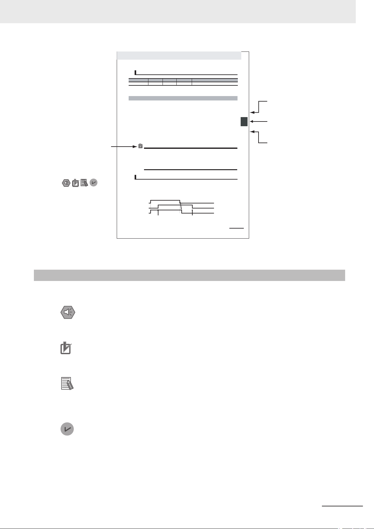
Special information
Icons indicate
precautions, additional
information, or reference
information.
Level-2 section heading
Level-1 section number
Level-3 section heading
The level-1 section number
is given.
The level-2 section heading
is given.
The level-3 section heading
is given.
3-3
3
Axis Command Instructions
NJ-series Motion Control Instructions Reference Manual (W508)
r
ew
oP
_
C
M
3
noitcnuF
* Specify an Axis Variable that was created in the Axis Basic Settings of the Sysmac Studio. (The default axis variable names
are MC_Axis***.)
• When
Enable changes to TRUE, the axis specified by Axis is made ready to operate.
You can control the axis when it is ready to operate.
• When Enable changes to FALSE, the ready status is cleared for the axis specified by Axis.
You cannot control the axis after the ready status is cl eared because it will not acknowledge operation commands. Also, an error occurs if a motion command is executed for an axis for which the
ready status is cleared. You can execute the MC_Power (Power Servo) and MC_Reset (Reset Axis
Error) instructions even for axes that are not ready.
• You can use this instruction to disable the operation of axes while they are in motion. In this case,
CommandAborted will change to TRUE. Output of the operation comman
d will stop and the axis will
not longer be ready for operation.
• If home is not defined for a Servomotor with an absolute encoder, compensation is performed using
the absolute encoder home offset to define home when the axis is ready to operate.
For details on the absolute encoder home offset, refer to the
NJ-series CPU Unit Motion Control
U
ser’s Manual (Cat. No. W507).
Precautions for Correct UsePrecautions for Correct Use
• You can use this instruction for servo axes and virtual servo axes. If the instruction is used for
encoder axes or virtual encoder axes, an error will occur.
• Executing this Instruction for the Master Axis of Synchronized Control
When master axis operation is disabled for a vertical axis, the position of the master axis may
change rapidly. This may cause the motion of th e slave axis to change rapidly. Take suitable
measures to prevent the slave axis from moving rapidly, such as applying a brake to the master axis or leaving master axis operation enabled until after synchronized control is completed.
• W
hen Enable changes to TRUE, Busy (Executing) changes to TRUE to indicate that the instruction
was acknowledged.
• After the axis becomes ready for operation, Status (Ser vo ON) changes to TRUE.
• W
hen Enable changes to FALSE, Busy (Executing) changes to FALSE. Status (Servo ON) changes
t
o FALSE when ready status is cleared. Status (Servo ON) outputs the axis ready status regardless
o
f whether Enable is TRUE or FALSE.
In-Out
Variables
Name Meaning Data type Valid range Description
Axis Axis _sAXIS_REF ---
Specify the axis.
*
Function
Timing Charts
Enable
Status
Busy
The specified axis becomes
ready for operation.
Rea
dy status is cleared for the
specified axis.
Manual Structure
Special Information
NY-series Motion Control Instructions Reference Manual (W561)
Note These pages are for illustrative purposes only. They may not literally appear in this manual.
Special information in this manual is classified as follows:
Precautions for Safe Use
Precautions on what to do and what not to do to ensure safe usage of the product.
Precautions for Correct Use
Precautions on what to do and what not to do to ensure proper operation and performance.
Additional Information
Additional information to read as required.
This information is provided to increase understanding or make operation easier
Information on dif
and for different versions of the Sysmac Studio is given.
Version Information
ferences in specifications and functionality for Controller with different unit versions
.
5
Page 8

Manual Structure
6
NY-series Motion Control Instructions Reference Manual (W561)
Page 9

Sections in this Manual
1
2
3
4
5
A
I
1
2
3
4
5
A
I
Introduction to Motion Control Instructions
V
ariables and Instructions
Axis Command Instructions
Axes Group Instructions
Common Command Instructions
Appendices
Index
Sections in this Manual
NY-series Motion Control Instructions Reference Manual (W561)
7
Page 10

CONTENTS
CONTENTS
Introduction .............................................................................................................. 1
Intended Audience
Applicable Products ......................................................................................................................................... 1
Relevant Manuals..................................................................................................... 2
Manual Structure...................................................................................................... 4
Page Structure.................................................................................................................................................4
Special Information .......................................................................................................................................... 5
Sections in this Manual ........................................................................................... 7
Terms and Conditions Agreement........................................................................ 13
Warranty, Limitations of Liability ....................................................................................................................13
Application Considerations ............................................................................................................................14
Disclaimers ....................................................................................................................................................14
...........................................................................................................................................1
Safety Precautions................................................................................................. 16
Precautions for Safe Use ...................................................................................... 17
Precautions for Correct Use ................................................................................. 18
Regulations and Standards .................................................................................. 19
Versions.................................................................................................................. 20
Checking Versions.........................................................................................................................................20
Related Manuals..................................................................................................... 22
Revision History..................................................................................................... 25
Section 1 Introduction to Motion Control Instructions
1-1 Motion Control Instructions..................................................................................................1-2
1-1-1
1-1-2 Overview of Motion Control Instructions .....................................................................................1-2
1-1-3 Precautions for Master and Auxiliary Axes in Synchronized Control ..........................................1-6
1-2 Basic Information on Motion Control Instructions ............................................................. 1-8
1-2-1 Motion Control Instruction Names...............................................................................................1-8
1-2-2 Languages for Motion Control Instructions .................................................................................1-8
1-2-3 Motion Control Instruction Locations...........................................................................................1-9
1-2-4 Multi-execution of Motion Control Instructions ..........................................................................1-17
1-2-5 Online Editing of Motion Control Instructions ............................................................................1-18
1-2-6 Changes in the Operating Mode of the Controller.....................................................................1-18
Function Blocks for PLCopen® Motion Control ...........................................................................1-2
Section 2 Variables and Instructions
2-1 Variables ................................................................................................................................. 2-2
2-1-1
2-1-2 Axis Variables..............................................................................................................................2-4
8
MC Common Variables ...............................................................................................................2-3
NY-series Motion Control Instructions Reference Manual (W561)
Page 11

2-1-3 Axes Group Variables................................................................................................................2-10
2-1-4
2-1-5 Output Variables for Motion Control Instructions.......................................................................2-27
2-1-6 In-Out Variables for Motion Control Instructions........................................................................2-30
Input Variables for Motion Control Instructions..........................................................................2-12
2-2 Instructions ..........................................................................................................................2-33
2-2-1 Common Commands ................................................................................................................2-33
2-2-2 Axis Commands ........................................................................................................................2-33
2-2-3 Axes Group Commands............................................................................................................2-35
2-3 PDO Mapping .......................................................................................................................2-37
2-3-1 Required Objects ......................................................................................................................2-37
2-3-2 Objects Required for Specific Instructions ................................................................................2-38
Section 3 Axis Command Instructions
MC_Power.........................................................................................................................................3-3
V
ariables .......................................................................................................................................................3-3
Function ........................................................................................................................................................3-4
MC_MoveJog .................................................................................................................................... 3-8
Variables.......................................................................................................................................................3-8
Function ........................................................................................................................................................3-9
MC_Home........................................................................................................................................3-18
Variables.....................................................................................................................................................3-18
Function ......................................................................................................................................................3-19
MC_HomeWithParameter ..............................................................................................................3-41
Variables.....................................................................................................................................................3-41
Function ......................................................................................................................................................3-45
MC_Move ........................................................................................................................................3-48
Variables.....................................................................................................................................................3-48
Function ......................................................................................................................................................3-50
MC_MoveAbsolute ......................................................................................................................... 3-53
Variables.....................................................................................................................................................3-53
Function ......................................................................................................................................................3-55
Sample Programming 1 ..............................................................................................................................3-61
Sample Programming 2 ..............................................................................................................................3-70
MC_MoveRelative...........................................................................................................................3-80
Variables.....................................................................................................................................................3-80
Function ......................................................................................................................................................3-82
MC_MoveVelocity...........................................................................................................................3-88
Variables.....................................................................................................................................................3-88
Function ......................................................................................................................................................3-90
Sample Programming .................................................................................................................................3-94
MC_MoveZeroPosition ................................................................................................................3-104
Variables...................................................................................................................................................3-104
Function ....................................................................................................................................................3-106
MC_MoveFeed .............................................................................................................................. 3-111
Variables................................................................................................................................................... 3-111
Function .................................................................................................................................................... 3-115
Sample Programming ...............................................................................................................................3-127
MC_Stop........................................................................................................................................3-140
Variables...................................................................................................................................................3-140
Function ....................................................................................................................................................3-141
MC_ImmediateStop......................................................................................................................3-149
Variables...................................................................................................................................................3-149
Function ....................................................................................................................................................3-150
MC_SetPosition............................................................................................................................3-154
CONTENTS
NY-series Motion Control Instructions Reference Manual (W561)
9
Page 12

CONTENTS
MC_SetOverride ...........................................................................................................................3-161
MC_ResetFollowingError ............................................................................................................3-167
MC_CamIn.....................................................................................................................................3-174
MC_CamOut..................................................................................................................................3-232
MC_CamMonitor...........................................................................................................................3-237
MC_GearIn ....................................................................................................................................3-246
MC_GearInPos..............................................................................................................................3-267
MC_GearOut .................................................................................................................................3-289
MC_MoveLink ............................................................................................................................... 3-294
MC_CombineAxes........................................................................................................................3-317
MC_Phasing..................................................................................................................................3-328
MC_TorqueControl.......................................................................................................................3-335
MC_SetTorqueLimit .....................................................................................................................3-348
MC_ZoneSwitch ...........................................................................................................................3-355
MC_TouchProbe...........................................................................................................................3-361
MC_AbortTrigger..........................................................................................................................3-381
Variables ...................................................................................................................................................3-154
Function
Variables ...................................................................................................................................................3-161
Function ....................................................................................................................................................3-162
Variables ...................................................................................................................................................3-167
Function ....................................................................................................................................................3-168
Variables ...................................................................................................................................................3-174
Function ....................................................................................................................................................3-178
Sample Programming 1 ............................................................................................................................3-201
Sample Programming 2 ............................................................................................................................3-212
Variables ...................................................................................................................................................3-232
Function ....................................................................................................................................................3-233
Variables ...................................................................................................................................................3-237
Function ....................................................................................................................................................3-240
Precautions for Correct Use .....................................................................................................................3-245
Variables ...................................................................................................................................................3-246
Function ....................................................................................................................................................3-248
Sample Programming ...............................................................................................................................3-255
Variables ...................................................................................................................................................3-267
Function ....................................................................................................................................................3-270
Sample Programming ...............................................................................................................................3-277
Variables ...................................................................................................................................................3-289
Function ....................................................................................................................................................3-290
Variables ...................................................................................................................................................3-294
Function ....................................................................................................................................................3-297
Sample Programming ...............................................................................................................................3-306
Variables ...................................................................................................................................................3-317
Function ....................................................................................................................................................3-319
Variables ...................................................................................................................................................3-328
Function ....................................................................................................................................................3-330
Variables ...................................................................................................................................................3-335
Function ....................................................................................................................................................3-337
Variables ...................................................................................................................................................3-348
Function ....................................................................................................................................................3-350
Variables ...................................................................................................................................................3-355
Function ....................................................................................................................................................3-356
Variables ...................................................................................................................................................3-361
Function ....................................................................................................................................................3-364
Sample Programming ...............................................................................................................................3-374
Variables ...................................................................................................................................................3-381
....................................................................................................................................................3-155
10
NY-series Motion Control Instructions Reference Manual (W561)
Page 13

CONTENTS
Function ....................................................................................................................................................3-382
MC_AxesObserve
Variables ...................................................................................................................................................3-385
Function ....................................................................................................................................................3-387
MC_SyncMoveVelocity ................................................................................................................ 3-391
Variables ...................................................................................................................................................3-391
Function ....................................................................................................................................................3-393
MC_SyncMoveAbsolute ..............................................................................................................3-401
Variables ...................................................................................................................................................3-401
Function ....................................................................................................................................................3-403
MC_Reset......................................................................................................................................3-408
Variables ...................................................................................................................................................3-408
Function ....................................................................................................................................................3-409
MC_ChangeAxisUse ....................................................................................................................3-412
Variables ...................................................................................................................................................3-412
Function ....................................................................................................................................................3-413
MC_DigitalCamSwitch .................................................................................................................3-416
Variables ...................................................................................................................................................3-416
Function ....................................................................................................................................................3-418
Sample Programming ...............................................................................................................................3-427
MC_TimeStampToPos .................................................................................................................3-436
Variables ...................................................................................................................................................3-436
Function ....................................................................................................................................................3-437
Sample Programming ...............................................................................................................................3-440
MC_SyncOffsetPosition ..............................................................................................................3-448
Variables ...................................................................................................................................................3-448
Function ....................................................................................................................................................3-450
MC_OffsetPosition ....................................................................................................................... 3-458
Variables ...................................................................................................................................................3-458
Function ....................................................................................................................................................3-460
.........................................................................................................................3-385
Section 4 Axes Group Instructions
MC_GroupEnable ............................................................................................................................. 4-2
V
ariables .......................................................................................................................................................4-2
Function ........................................................................................................................................................4-3
MC_GroupDisable ............................................................................................................................ 4-6
Variables.......................................................................................................................................................4-6
Function ........................................................................................................................................................4-7
MC_MoveLinear.............................................................................................................................. 4-11
Variables.....................................................................................................................................................4-11
Function ......................................................................................................................................................4-13
Sample Programming .................................................................................................................................4-24
MC_MoveLinearAbsolute ..............................................................................................................4-40
Variables.....................................................................................................................................................4-40
Function ......................................................................................................................................................4-42
MC_MoveLinearRelative................................................................................................................4-43
Variables.....................................................................................................................................................4-43
Function ......................................................................................................................................................4-45
MC_MoveCircular2D ......................................................................................................................4-46
Variables.....................................................................................................................................................4-46
Function ......................................................................................................................................................4-49
Sample Programming .................................................................................................................................4-61
MC_GroupStop...............................................................................................................................4-74
Variables.....................................................................................................................................................4-74
NY-series Motion Control Instructions Reference Manual (W561)
11
Page 14

CONTENTS
MC_GroupImmediateStop
MC_GroupSetOverride ..................................................................................................................4-86
MC_GroupReadPosition................................................................................................................4-91
MC_ChangeAxesInGroup..............................................................................................................4-95
MC_GroupSyncMoveAbsolute......................................................................................................4-99
MC_GroupReset ........................................................................................................................... 4-106
Function ......................................................................................................................................................4-76
.............................................................................................................4-82
Variables .....................................................................................................................................................4-82
Function ......................................................................................................................................................4-83
Variables .....................................................................................................................................................4-86
Function ......................................................................................................................................................4-87
Variables .....................................................................................................................................................4-91
Function ......................................................................................................................................................4-92
Variables .....................................................................................................................................................4-95
Function ......................................................................................................................................................4-96
Variables .....................................................................................................................................................4-99
Function ....................................................................................................................................................4-101
Variables ...................................................................................................................................................4-106
Function ....................................................................................................................................................4-107
Section 5 Common Command Instructions
MC_SetCamTableProperty ..............................................................................................................5-2
V
ariables .......................................................................................................................................................5-2
Function ........................................................................................................................................................5-3
MC_SaveCamTable ..........................................................................................................................5-8
Variables.......................................................................................................................................................5-8
Function ........................................................................................................................................................5-9
MC_Write.........................................................................................................................................5-13
Variables.....................................................................................................................................................5-13
Function ......................................................................................................................................................5-16
MC_GenerateCamTable .................................................................................................................5-18
Variables.....................................................................................................................................................5-18
Function ......................................................................................................................................................5-20
Sample Programming .................................................................................................................................5-33
MC_WriteAxisParameter ...............................................................................................................5-47
Variables.....................................................................................................................................................5-47
Function ......................................................................................................................................................5-48
MC_ReadAxisParameter................................................................................................................5-61
Variables.....................................................................................................................................................5-61
Function ......................................................................................................................................................5-63
Appendices
A-1 Instructions for Which Multi-execution Is Supported ....................................................... A-2
A-1-1
A-1-2 State Transitions and Instructions for which Multi-execution Is Supported................................ A-4
A-2 Connecting to NX Units...................................................................................................... A-10
A-3 Version Information ............................................................................................................ A-11
Index
12
Axis and Axes Group Status ...................................................................................................... A-2
NY-series Motion Control Instructions Reference Manual (W561)
Page 15

Terms and Conditions Agreement
Terms and Conditions Agreement
Warranty, Limitations of Liability
Warranties
Exclusive Warranty
Omron’s exclusive warranty is that the Products will be free from defects in materials and work-
manship for a period of twelve months from the date of sale by Omron (or such other period ex-
pressed in writing by Omron). Omron disclaims all other warranties, express or implied.
Limitations
OMRON MAKES NO WARRANTY OR REPRESENTATION, EXPRESS OR IMPLIED, ABOUT
NON-INFRINGEMENT, MERCHANTABILITY OR FITNESS FOR A PARTICULAR PURPOSE OF
THE PRODUCTS. BUYER ACKNOWLEDGES THAT IT ALONE HAS DETERMINED THAT THE
PRODUCTS WILL SUITABLY MEET THE REQUIREMENTS OF THEIR INTENDED USE.
Omron further disclaims all warranties and responsibility of any type for claims or expenses based
on infringement by the Products or otherwise of any intellectual property right.
Buyer Remedy
Omron’s sole obligation hereunder shall be, at Omron’s election, to (i) replace (in the form originally
shipped with Buyer responsible for labor charges for removal or replacement thereof) the non-com-
plying Product, (ii) repair the non-complying Product, or (iii) repay or credit Buyer an amount equal
to the purchase price of the non-complying Product; provided that in no event shall Omron be re-
sponsible for warranty, repair, indemnity or any other claims or expenses regarding the Products
unless Omron’s analysis confirms that the Products were properly handled, stored, installed and
maintained and not subject to contamination, abuse, misuse or inappropriate modification. Return
of any Products by Buyer must be approved in writing by Omron before shipment. Omron Compa-
nies shall not be liable for the suitability or unsuitability or the results from the use of Products in
combination with any electrical or electronic components, circuits, system assemblies or any other
materials or substances or environments. Any advice, recommendations or information given orally
or in writing, are not to be construed as an amendment or addition to the above warranty.
See http://www.omron.com/global/ or contact your Omron representative for published information.
Limitation on Liability; Etc
OMRON COMPANIES SHALL NOT BE LIABLE FOR SPECIAL, INDIRECT, INCIDENTAL, OR CON-
SEQUENTIAL DAMAGES, LOSS OF PROFITS OR PRODUCTION OR COMMERCIAL LOSS IN ANY
NY-series Motion Control Instructions Reference Manual (W561)
13
Page 16

Terms and Conditions Agreement
WAY CONNECTED WITH THE PRODUCTS, WHETHER SUCH CLAIM IS BASED IN CONTRACT,
W
ARRANTY, NEGLIGENCE OR STRICT LIABILITY.
Further, in no event shall liability of Omron Companies exceed the individual price of the Product on
which liability is asserted.
Application Considerations
Suitability of Use
Omron Companies shall not be responsible for conformity with any standards, codes or regulations
which apply to the combination of the Product in the Buyer
er’s request, Omron will provide applicable third party certification documents identifying ratings and
limitations of use which apply to the Product. This information by itself is not sufficient for a complete
determination of the suitability of the Product in combination with the end product, machine, system, or
other application or use. Buyer shall be solely responsible for determining appropriateness of the par-
ticular Product with respect to Buyer’s application, product or system. Buyer shall take application re-
sponsibility in all cases.
’s application or use of the Product. At Buy-
NEVER USE THE PRODUCT FOR AN APPLICATION INVOLVING SERIOUS RISK TO LIFE OR
PROPERTY OR IN LARGE QUANTITIES WITHOUT ENSURING THAT THE SYSTEM AS A WHOLE
HAS BEEN DESIGNED TO ADDRESS THE RISKS, AND THAT THE OMRON PRODUCT(S) IS
PROPERLY RATED AND INSTALLED FOR THE INTENDED USE WITHIN THE OVERALL EQUIP-
MENT OR SYSTEM.
Programmable Products
Omron Companies shall not be responsible for the user’s programming of a programmable Product, or
any consequence thereof.
Disclaimers
Performance Data
Data presented in Omron Company websites, catalogs and other materials is provided as a guide for
the user in determining suitability and does not constitute a warranty
Omron’s test conditions, and the user must correlate it to actual application requirements. Actual per-
formance is subject to the Omron’s Warranty and Limitations of Liability.
. It may represent the result of
14
Change in Specifications
Product specifications and accessories may be changed at any time based on improvements and oth-
er reasons. It is our practice to change part numbers when published ratings or features are changed,
or when significant construction changes are made. However
NY-series Motion Control Instructions Reference Manual (W561)
, some specifications of the Product may
Page 17

Terms and Conditions Agreement
be changed without any notice. When in doubt, special part numbers may be assigned to fix or estab-
lish key specifications for your application. Please consult with your Omron’
time to confirm actual specifications of purchased Product.
s representative at any
Errors and Omissions
Information presented by Omron Companies has been checked and is believed to be accurate; how-
ever
, no responsibility is assumed for clerical, typographical or proofreading errors or omissions.
NY-series Motion Control Instructions Reference Manual (W561)
15
Page 18

Safety Precautions
Safety Precautions
Refer to the following manuals for safety precautions.
• NY-series Industrial Box PC Hardware User’s Manual (Cat. No. W556)
• NY-series Industrial Panel PC Hardware User’s Manual (Cat. No. W557)
• NY-series Industrial Panel PC / Industrial Box PC Software User’s Manual (Cat. No. W558)
16
NY-series Motion Control Instructions Reference Manual (W561)
Page 19

Precautions for Safe Use
Precautions for Safe Use
Refer to the following manuals for precautions for safe use.
• NY-series Industrial Box PC Hardware User’s Manual (Cat. No. W556)
• NY-series Industrial Panel PC Hardware User’s Manual (Cat. No. W557)
• NY-series Industrial Panel PC / Industrial Box PC Software User’s Manual (Cat. No. W558)
NY-series Motion Control Instructions Reference Manual (W561)
17
Page 20

Precautions for Correct Use
Precautions for Correct Use
Refer to the following manuals for precautions for correct use.
• NY-series Industrial Box PC Hardware User’s Manual (Cat. No. W556)
• NY-series Industrial Panel PC Hardware User’s Manual (Cat. No. W557)
• NY-series Industrial Panel PC / Industrial Box PC Software User’s Manual (Cat. No. W558)
18
NY-series Motion Control Instructions Reference Manual (W561)
Page 21

Regulations and Standards
Refer to the following manuals for Regulations and Standards.
• NY-series Industrial Box PC Hardware User’s Manual (Cat. No. W556)
• NY-series Industrial Panel PC Hardware User’s Manual (Cat. No. W557)
Regulations and Standards
NY-series Motion Control Instructions Reference Manual (W561)
19
Page 22
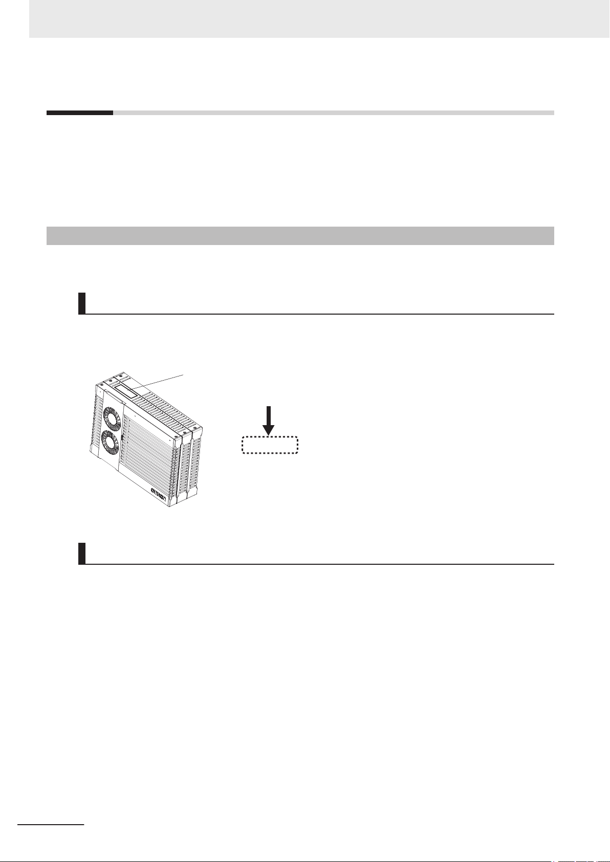
ID information indication
Unit version
Ver.1.£
£
Versions
Versions
Hardware revisions and unit versions are used to manage the hardware and software in NY-series
Controllers and EtherCAT slaves. The hardware revision or unit version is updated each time there is
a change in hardware or software specifications. Even when two Units or EtherCAT slaves have the
same model number, they will have functional or performance differences if they have different hard-
ware revisions or unit versions.
Checking Versions
You can check versions on the ID information indications or with the Sysmac Studio.
Checking Unit Versions on ID Information Indications
The unit version is given on the ID information indication on the side of the product.
The ID information on an NY-series NY5£2-££££ Controller is shown below.
Checking Unit Versions with the Sysmac Studio
You can use the Sysmac Studio to check unit versions. The procedure is different for Units and for
EtherCA
T slaves.
Checking the Unit Version of an NY-series Controller
20
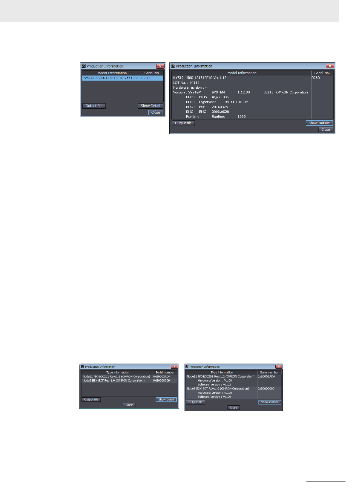
You can use the Production Information while the Sysmac Studio is online to check the unit version
of a Unit. You can do this only for the Controller.
1 Right-click CPU Rack under Configurations and Setup - CPU/Expansion Racks in the Multi-
view Explorer
The Production Information Dialog Box is displayed.
Changing Information Displayed in Production Information Dialog Box
, and select Production Information.
1 Click the Show Outline or Show Detail Button at the lower right of the Production Information
Dialog Box.
NY-series Motion Control Instructions Reference Manual (W561)
Page 23
Versions
The view will change between the production information details and outline.
Outline View Detail View
The information that is displayed is different for the Outline View and Detail View. The Detail
iew displays the unit version, hardware revision, and other versions. The Outline View dis-
V
plays only the unit version.
Checking the Unit Version of an EtherCAT Slave
You can use the Production Information while the Sysmac Studio is online to check the unit version
of an EtherCAT slave.
Use the following procedure to check the unit version.
1 Double-click EtherCA
click EtherCAT under Configurations and Setup and select Edit from the menu.
The EtherCAT Tab Page is displayed.
T under Configurations and Setup in the Multiview Explorer. Or, right-
2 Right-click the master on the EtherCAT Tab Page and select Display Production Information.
The Production Information Dialog Box is displayed.
The unit version is displayed after “Rev
Changing Information Displayed in Production Information Dialog Box
.”
1 Click the Show Detail or Show Outline Button at the lower right of the Production Information
Dialog Box.
The view will change between the production information details and outline.
Outline View Detail View
NY-series Motion Control Instructions Reference Manual (W561)
21
Page 24

Related Manuals
Related Manuals
The followings are the manuals related to this manual. Use these manuals for reference.
Manual name Cat. No. Model numbers Application Description
NY-series
IPC Machine Controller
Industrial Panel PC
Hardware User
NY-series
IPC Machine Controller
Industrial Box PC
Hardware User
NY-series
IPC Machine Controller
Industrial Panel PC / Industrial
Box PC
Setup User
NY-series
IPC Machine Controller
Industrial Panel PC / Industrial
Box PC
Software User
NY-series
Instructions Reference Manual
NY-series
IPC Machine Controller
Industrial Panel PC / Industrial
Box PC
Motion Control User
NY-series
Motion Control Instructions
Reference Manual
’s Manual
’s Manual
’s Manual
’s Manual
’s Manual
W557
W556
W568
W558
W560
W559
W561
NY532-££££
NY512-££££
NY532-££££
NY512-££££
NY532-££££
NY512-££££
NY532-££££
NY512-££££
NY532-££££
NY512-££££
NY532-££££
NY512-££££
Learning the basic
specifications of the
NY-series Industrial
Panel PCs, including
introductory information, designing, installation, and maintenance.
Mainly hardware information is provided.
Learning the basic
specifications of the
NY-series Industrial
Box PCs, including
introductory information, designing, installation, and maintenance.
Mainly hardware information is provided.
Learning about initial
setting of the NY-series Industrial PCs
and preparations to
use Controllers.
Learning how to program and set up the
Controller functions
of an NY-series Industrial PC.
Learning detailed
specifications on the
basic instructions of
an NY
-series Indus-
trial PC.
Learning about motion control settings
and programming
concepts of an NYseries Industrial PC.
Learning about the
specifications of the
motion control instructions of an NY
series Industrial PC.
-
An introduction to the entire NY-series system is provided along with the following information on the Industrial Panel PC.
• Features and system configuration
• Introduction
• Part names and functions
• General specifications
• Installation and wiring
• Maintenance and inspection
An introduction to the entire NY-series system is provided along with the following information on the Industrial Box PC.
• Features and system configuration
• Introduction
• Part names and functions
• General specifications
• Installation and wiring
• Maintenance and inspection
The following information is provided on an
introduction to the entire NY-series system.
• Two OS systems
• Initial settings
• Industrial PC Support Utility
• NYCompolet
• Industrial PC API
• Backup and recovery
The following information is provided on the
NY-series Controller functions.
• Controller operation
• Controller features
• Controller settings
• Programming based on IEC 61131-3 lan-
guage specifications
The instructions in the instruction set (IEC
61131-3 specifications) are described.
The settings and operation of the Controller
and programming concepts for motion control are described.
The motion control instructions are described.
22
NY-series Motion Control Instructions Reference Manual (W561)
Page 25

Manual name Cat. No. Model numbers Application Description
NY-series
IPC Machine Controller
Industrial Panel PC
/ Industrial
Box PC
Built-in EtherCA
Manual
NY-series
IPC Machine Controller
Industrial Panel PC
/ Industrial
Box PC
Built-in EtherNet/IP™ Port Us-
’s Manual
er
NJ/NY-series
NC Integrated Controller
’s Manual
User
NJ/NY-series
G code
Instructions Reference Manual
NY-series
roubleshooting Manual
T
Sysmac Studio Version 1
Operation Manual
CNC Operator
Operation Manual
NX-series
EtherCA
User’s Manual
T® Port User’s
T® Coupler Unit
W562
W563
O030 NJ501-5300
O031 NJ501-5300
W564
W504 SYSMAC
O032
W519
NY532-££££
NY512-££££
NY532-££££
NY512-££££
NY532-5400
NY532-5400
NY532-££££
NY512-££££
-SE2£££
SYSMAC-RTNC0£
££D
NX-ECC£££
Using the built-in
EtherCAT port in an
NY-series Industrial
PC.
Using the built-in
EtherNet/IP port in
an NY-series Industrial PC.
Performing numerical
control with NJ/NYseries Controllers.
Learning about the
specifications of the
G code/M code instructions.
Learning about the
errors that may be
detected in an NYseries Industrial PC.
Learning about the
operating procedures
and functions of the
Sysmac Studio.
Learning an introduction of the CNC Operator and how to
use it.
Learning how to use
the NX-series EtherCAT Coupler Unit
and EtherCAT Slave
Terminals.
Information on the built-in EtherCAT port is
provided.
This manual provides an introduction and
provides information on the configuration,
features, and setup.
Information on the built-in EtherNet/IP port
is provided.
Information is provided on the basic setup,
tag data links, and other features.
Describes the functionality to perform the
numerical control.
The G code/M code instructions are described.
Concepts on managing errors that may be
detected in an NY-series Controller and information on individual errors are described.
Describes the operating procedures of the
Sysmac Studio.
An introduction of the CNC Operator, installation procedures, basic operations, connection operations, and operating procedures for main functions are described.
The following items are described: the overall system and configuration methods of an
EtherCAT Slave Terminal (which consists of
an NX-series EtherCAT Coupler Unit and
NX Units), and information on hardware,
setup, and functions to set up, control, and
monitor NX Units through EtherCAT.
Related Manuals
NY-series Motion Control Instructions Reference Manual (W561)
23
Page 26

Related Manuals
Manual name Cat. No. Model numbers Application Description
NX-series
NX Units
’s Manual
User
NX-series
Data Reference Manual
GX-series EtherCAT Slave
Units
’s Manual
User
AC Servomotors/Servo Drives
1S-series with
Built-in EtherCA
cations User's Manual
AC Servomotors/Servo Drives
G5 Series with
Built-in EtherCA
cations User's Manual
T® Communi-
T® Communi-
W521
W522
W592
W566
W523
W524
W540
W565
W567
W525
W488
I586
I621
I576
I577
NX-ID££££
NX-IA££££
NX-OC££££
NX-OD££££
NX-MD££££
NX-AD££££
NX-DA££££
NX-HAD£££
NX-TS££££
NX-HB££££
NX-PD1£££
NX-PF0£££
NX-PC0£££
NX-TBX01
NX-EC0£££
NX-ECS£££
NX-PG0£££
NX-CIF£££
NX-RS££££
NX-ILM£££
NX-££££££
GX-ID££££
GX-OD££££
GX-OC££££
GX-MD££££
GX-AD££££
GX-DA££££
GX-EC££££
-ID££
XWT
XWT-OD££
R88M-1£
R88D-1SN£-ECT
R88M-1AL£/ -1AM
£
R88D-1SAN£-ECT
R88M-K£
R88D-KN£-ECT
R88L-EC-£
R88D-KN£-ECT
-L
Learning how to use
NX Units.
Referencing lists of
the data that is required to configure
systems with NX-series Units.
Learning how to use
the EtherCA
I/O terminals.
Learning how to use
the Servomotors/
Servo Drives with
built-in EtherCAT
Communications.
Learning how to use
the AC Servomotors/
Servo Drives with
built-in EtherCAT
Communications.
T remote
Describes the hardware, setup methods,
and functions of the NX Units.
Manuals are available for the following
Units.
Digital I/O Units, Analog I/O Units, System
Units, Position Interface Units, Communications Interface Units, Load Cell Input Unit,
and IO-Link Master Units.
Lists of the power consumptions, weights,
and other NX Unit data that is required to
configure systems with NX-series Units are
provided.
Describes the hardware, setup methods
and functions of the EtherCAT remote I/O
terminals.
Describes the hardware, setup methods
and functions of the Servomotors/Servo
Drives with built-in EtherCAT Communications.
Describes the hardware, setup methods
and functions of the AC Servomotors/Servo
Drives with built-in EtherCAT Communications.
The Linear Motor Type models and dedicated models for position control are available
in G5-series.
24
NY-series Motion Control Instructions Reference Manual (W561)
Page 27

Revision History
W561-E1-05
R
evision code
Cat. No.
A manual revision code appears as a suffix to the catalog number on the front and back covers of the
manual.
Revision History
Revision
code
01 September 2016 Original production
02 April 2017 Corrected mistakes.
03 October 2017 Corrected mistakes.
04 January 2019 Corrected mistakes.
05 July 2019
Date Revised content
• Made changes accompanying the addition of 1S-series AC Servomotors/
Servo Drives.
• Made changes accompanying th addition of the MC_CamMonitor (Cam Mon-
itor) instruction and the MC_Of
instruction.
• Made changes accompanying the release of Sysmac Studio version 1.29.
fsetPosition (Position Offset Compensation)
NY-series Motion Control Instructions Reference Manual (W561)
25
Page 28

Revision History
26
NY-series Motion Control Instructions Reference Manual (W561)
Page 29

1
Introduction to Motion Control Instructions
This section gives an introduction to motion control instructions supported by NY-series Controller
1-1 Motion Control Instructions .......................................................................... 1-2
1-1-1 Function Blocks for PLCopen® Motion Control............................................... 1-2
1-1-2 Overview of Motion Control Instructions ......................................................... 1-2
1-1-3 Precautions for Master and Auxiliary Axes in Synchronized Control.............. 1-6
1-2 Basic Information on Motion Control Instructions .....................................1-8
1-2-1 Motion Control Instruction Names .................................................................. 1-8
1-2-2 Languages for Motion Control Instructions ..................................................... 1-8
1-2-3 Motion Control Instruction Locations .............................................................. 1-9
1-2-4 Multi-execution of Motion Control Instructions.............................................. 1-17
1-2-5 Online Editing of Motion Control Instructions................................................ 1-18
1-2-6 Changes in the Operating Mode of the Controller ........................................ 1-18
s.
1
NY-series Motion Control Instructions Reference Manual (W561)
1-1
Page 30

1 Introduction to Motion Control Instructions
1-1
1-1-1
Motion Control Instructions
Motion control instructions are used in the user program to execute motion controls for an NY-series
Controller. These instructions are defined as function blocks.
The motion control instructions of the MC Function Module are based on the technical specifications of
function blocks for PLCopen® motion control.
There are two types of motion control instructions: PLCopen®-defined instructions and instructions that
are unique to the MC Function Module.
This section provides an overview of the PLCopen® motion control function blocks and motion control
instructions.
For details on motion control instructions, refer to the NY-series Industrial Panel PC / Industrial Box PC
Motion Control User’s Manual (Cat. No. W559).
Refer to the NX-series Position Interface Units User’s Manual (Cat. No. W524) for information on us-
ing the NX-series Position Interface Units.
Function Blocks for PLCopen® Motion Control
1-1-2
PLCopen® standardizes motion control function blocks to define a program interface for the languages
specified in IEC 61
Single-axis positioning, electronic cams, and multi-axes coordinated control are defined along with ba-
sic procedures for executing instructions.
By using PLCopen® motion control function blocks, programming can be more easily reused without
hardware dependence.
Costs for training and support are also reduced.
Additional Information
PLCopen
PLCopen® is a promotion body for IEC 61
worldwide membership structure.
IEC 61131-3 is an international standard for PLC programming.
PLCopen® Japan is the promotion committee for the Japanese market and consists of members that have concerns related to the Japanese market.
• The website of PLCopen® Japan is http://www.plcopen-japan.jp/.
• The website of PLCopen® Europe (headquarters) is http://www.plcopen.org/.
131-3 (JIS B 3503).
®
131-3 that has its headquarters in Europe and a
Overview of Motion Control Instructions
1-2
This section describes items defined in the technical specifications of function blocks for PLCopen
motion control and provides an overview of their application in the MC Function Module.
Types of Motion Control Instructions
The following table list the different types of motion control instructions.
NY-series Motion Control Instructions Reference Manual (W561)
®
Page 31

1 Introduction to Motion Control Instructions
Classification Type Functional group Description
Instructions for
common commands
Instructions for
axis commands
Instructions for
axes group commands
Common administration instructions
Single-axis motion
instructions
Single-axis administration instructions
Multi-axes motion
instructions
Multi-axes administration instructions
Cam tables These instructions are used to control the com-
Parameters
Single-axis position control
Single-axis velocity control
Single-axis torque
control
Single-axis
synchronized control
Single-axis manual operation
Auxiliary functions
for single-axis control
Multi-axes coordinated control
Auxiliary functions
for multi-axes coordinated control
mon status of the MC Function Module, and to
manipulate and monitor data.
These instructions move single axes.
This instructions control or monitor axis status.
These instructions perform coordinated movement of an axes group.
These instructions control or monitor axes group
status.
1-1 Motion Control Instructions
1
1-1-2 Overview of Motion Control Instructions
State Transitions
State transitions are defined for axes, axes groups, and instruction execution.
For details on the state and state transitions of the MC Function Module, refer to the NY
-series
Industrial Panel PC / Industrial Box PC Motion Control User’s Manual (Cat. No. W559).
Execution and Status of Motion Control Instructions
Variables that start instruction execution or that indicate the execution status are defined as common
rules for the instructions.
There are two input variables that start instruction execution: Execute and Enable.
The output variables that indicate the execution status of an instruction include Busy, Done,
CommandAborted, and Error.
For detailed specifications of the MC Function Module, refer to the NY
Industrial Box PC Motion Control User’s Manual (Cat. No. W559).
Precautions for Correct Use
The timing in the timing charts that are given in this manual may not necessarily be the same as
the timing displayed for data traces on the Sysmac Studio.
Refer to the NY
-series Industrial Panel PC / Industrial Box PC Software User’s Manual (Cat.
No. W558) for details on data tracing.
-series Industrial Panel PC /
NY-series Motion Control Instructions Reference Manual (W561)
1-3
Page 32

Turning ON the Servo
Enable Status
ErrorID
PWR1
E
rror
MC_Power
Axis Axis
Busy
MC_Axis000
Pwr1_En
Pwr1_Status
Pwr1_Bsy
Pwr1_Err
Pwr1_ErrID
Checking to See If the Specified Axis Exists
Pwr1_Err
In1
EQ
In2
EQ
In3
In4
In5
NoAxisErr
Pwr1_ErrID
WORD#16#5460
1 Introduction to Motion Control Instructions
Error Processing
You execute motion control instructions to implement motion control with the MC Function Module.
When motion control instructions are executed, input parameters and instruction processing are
checked for errors.
If an error occurs in an instruction, the Error
an error code is output to ErrorID output variable.
There are two ways that you can use to program processing of errors for motion control instructions.
Error Processing for Individual Instructions
You can use the Error and ErrorID output variables from the instruction to process errors that occur
for each instruction.
The following example shows how to determine if an Illegal Axis Specification occurs for the in-
struction with the instance name PWR1.
The instructions are programmed so that error processing is executed if NoAxisErr changes to
TRUE.
output variable from the instruction changes to TRUE and
Error Processing for Different Types of Errors
You can use the error status that is provided by the system-defined variables for motion control to
process each type of error separately
The following example shows how to determine if a Slave Communications Error occurs for the ax-
is that is called MC_Axis000. The instructions are programmed so that error processing is executed
if ConnectErr changes to TRUE.
1-4
.
NY-series Motion Control Instructions Reference Manual (W561)
Page 33

Checking for Communications Errors between the CPU Unit and Servo Drive
Off
In1
EQ
In2
EQ
In3
In4
In5
ConnectErr
MC_
Axis000.MFaultLvl.Code
WORD#16#8440
1 Introduction to Motion Control Instructions
Changing Input Variables during Execution of Motion Control Instructions (Restarting Instructions)
If the values of the input variables to an instruction instance are changed while the motion control in-
struction is under execution and then Execute is changed to TRUE again, operation will follow the new
values.
1-1 Motion Control Instructions
1
1-1-2 Overview of Motion Control Instructions
For details on re-execution of MC Function Module instructions, refer to the NY
-series Industrial Panel
PC / Industrial Box PC Motion Control User’s Manual (Cat. No. W559).
Multi-execution of Instructions with Buf
ferMode
A different instruction instance can be executed during axis motion.
Y
ou can specify when a motion starts by setting an input variable called BufferMode.
The following Buffer Modes are supported for BufferMode.
• Aborting
fered
• Buf
• Blending Low
• Blending Previous
• Blending Next
• Blending High
In Aborting
mode, other motions are aborted and the function block is executed immediately.
: Abort (Aborting)
: Standby (Buffered)
: Blending with the low velocity (BlendingLow)
: Blending with the previous velocity (BlendingPrevious)
: Blending with the next velocity (BlendingNext)
: Blending with the high velocity (BlendingHigh)
In other buffer modes, the next instruction waits until an output variable such as Done or InVelocity
from the currently executed instruction changes to TRUE.
For Buffered mode, the next instruction is executed after the current instruction is executed and Done
changes to TRUE.
For the Blending modes, two instruction motions are executed consecutively without pausing. The
transition velocity between the two motions is selected from four buffer modes.
For the MC Function Module, BufferMode is also referred to as multi-execution of instructions.
For details on multi-execution of instructions for the MC Function Module, refer to the NY-series
Industrial Panel PC / Industrial Box PC Motion Control User’s Manual (Cat. No. W559).
Whether multi-execution of instructions is supported in the MC Function Module depends on the cur-
NY-series Motion Control Instructions Reference Manual (W561)
rent axis status, the current axes group status, and the instruction to execute. Refer to A-1 Instructions
for Which Multi-execution Is Supported on page A-2 for detailed information.
1-5
Page 34

1 Introduction to Motion Control Instructions
Structures Used for Motion Control
Information required for motion control are defined as structures in PLCopen® technical materials. Da-
ta type names and basic aspects are defined, but the contents of the structures are not defined.
The main data types defined in PLCopen® and the data types used in the MC Function Module are
shown in the following table.
Data type
PLCopen
AXIS_REF _sAXIS_REF This is a structure that contains information on the corre-
AXES_GROUP_REF _sGROUP_REF This is a structure that contains information on the corre-
TRIGGER_REF _sTRIGGER_REF This is a structure that contains information on trigger in-
INPUT_REF --- This is a structure that contains information relating to the
OUTPUT_REF _sOUTPUT_REF This is a structure relating to physical outputs.
As shown in the above table, the MC Function Module uses some data types that are defined by
PLCopen® and some that are defined specifically for the MC Function Module.
Refer to the NY
W559) for definitions of the data types and structures that are handled by the MC Motion Module.
®
-series Industrial Panel PC / Industrial Box PC Motion Control User’s Manual (Cat. No.
MC Function Module
sponding axis.
sponding axes group.
puts.
rigger specifications
• T
• Detection pattern information (positive, negative, both,
edge, level, pattern recognition, etc.)
input specifications. It may include virtual data.
This data type is not used by the MC Function Module.
Definition
1-1-3
Precautions for Master and Auxiliary Axes in Synchronized Control
Precautions that are related to sudden changes in velocity and conditions that lead to errors are given
below for master and auxiliary axes in synchronized control.
Sudden Changes in Velocity
When the velocity of the master or auxiliary axis changes suddenly when synchronized motion is start-
ed or during synchronized motion, the motion of the slave axis can change suddenly and sometimes
place an excessive load on the machine.
Take suitable precautions in the following cases because the velocity of the master or auxiliary axis
may change suddenly.
• When one of the following three instructions is executed for the master or auxiliary axis:
MC_ImmediateStop instruction
MC_ResetFollowingError instruction
MC_SyncMoveVelocity (Cyclic Synchronous Velocity Control) instruction
To ensure that the slave axis does not move suddenly, set suitable input parameters and execution
timing for the above instructions or execute them after synchronized control has been released.
1-6
NY-series Motion Control Instructions Reference Manual (W561)
Page 35

1 Introduction to Motion Control Instructions
• When the immediate stop input signal or limit stop input signal changes to TRUE for the master or
auxiliary axis
•
When the Servo turns OFF for the master or auxiliary axis
When the Servo is turned OFF when the master or auxiliary axis is a vertical axis, the position of the
axis may change suddenly.
Take suitable measures to prevent the slave axis from moving suddenly, such as applying a brake to
the master or auxiliary axis or turning OFF the Servo after synchronized control has been released.
• When you change the control mode of the Servo Drive
Take suitable precautions for changes in the velocity when an instruction is executed.
Set suitable input parameters for the instruction.
Conditions That Lead to Errors
The following conditions apply to NY-series Controllers.
Conditions for NY-series Controllers
1-1 Motion Control Instructions
1
1-1-3 Precautions for Master and Auxiliary Axes in Synchronized Control
When any of the following four conditions occurs for the master or auxiliary axis when synchronized
motion is started or during synchronized motion, a Master Axis Position Read Error or Auxiliary Ax-
is Position Read Error occurs for the slave axis.
The CommandAborted
at the same time.
• EtherCAT process data communications are not established.
• An EtherCAT Slave Communications Error occurs while EtherCAT communications are not es-
tablished.
• An Absolute Encoder Current Position Calculation Failed error occurs.
• The slave is disconnected.
The following occur if multi-execution of instructions is used for synchronized control instructions
for the slave axis.
• Even if the master or auxiliary axis is in one of the four conditions given above, multi-execution of
instructions is acknowledged normally and the instruction is buffered.
• The motion for the buffered instruction is started as normal if none of the above four conditions
exist.
Additional Information
If the MC_Home or MC_HomeWithParameter instruction is executed for the master or auxiliary
axis or if the MC_Power instruction is executed for an axis that uses an absolute encoder
slave ignores the changes in position of the master or auxiliary axis.
Therefore, the slave axis does not move suddenly when defining home.
output variable from the synchronized control instruction changes to TRUE
, the
NY-series Motion Control Instructions Reference Manual (W561)
1-7
Page 36

Input variables
Outp
ut variables
Omitted.
Omitted.
Omitted.
Output parameter
Body name
Instance name
Input parameters
In-out variable
Execute
Error
ErrorID
Command Aborted
MC_ABS_instance
Velocity
Done
Busy
Acceleration
MC_MoveAbsolute
Axis Axis
Position
Deceleration
Jer
k
Direction
BufferMode
Activ
e
MC_Axis001 Axis1
PTP_Absolute
PTP_Position
PTP_Velocity
PTP_Acc
PTP_Dec
PTP_Done
1 Introduction to Motion Control Instructions
1-2
1-2-1
1-2-2
Basic Information on Motion Control Instructions
This section describes basic specifications and restrictions for programming with motion control in-
structions for the MC Function Module built into the NY-series Controller.
For details on motion control instructions, refer to Section 3 Axis Command Instructions on page
3-1, Section 4 Axes Group Instructions on page 4-1, and Section 5 Common Command In-
structions on page 5-1.
Motion Control Instruction Names
All motion control instructions for the MC Function Module begin with "MC_".
To see whether an instruction is defined by PLCopen® or whether it is an instruction defined for the
MC Function Module itself, refer to 2-2 Instructions on page 2-33.
Languages for Motion Control Instructions
Motion control instructions of the MC Function Module can be used in the following programming lan-
guages.
•
Ladder diagrams (LD)
• Structured text (ST)
1-8
Ladder Diagrams (LD)
Instruction instances of motion control instructions are located in ladder diagrams.
The instruction instances can be named.
The following example shows the MC_MoveAbsolute (Absolute Positioning) instruction.
• The axis variable name of the Servo Drive or other device to control is specified with the in-out vari-
able Axis.
•
Motion conditions, such as the target position or target velocity, are specified with input variables.
NY-series Motion Control Instructions Reference Manual (W561)
Page 37

1 Introduction to Motion Control Instructions
1-2 Basic Information on Motion
• The status of the instruction or the status of the Servo Drive is output with output variables.
•
If input parameters are omitted, input variables are set to default values.
Structured Text (ST)
The instruction instance name is specified.
Instruction variables are written from upper left to lower left, then upper right to lower right.
The following example shows MC_MoveAbsolute (Absolute Positioning).
MC_ABS_instance (
Axis := MC_Axis001 ,
Execute := PTP_Absolute ,
Position := PTP_Position ,
Velocity := PTP_Velocity ,
Acceleration := PTP_Acc ,
Deceleration := PTP_Dec ,
Jerk := PTP_Jerk ,
Direction := _mcNoDirection ,
BufferMode := _mcAborting ,
Axis => MC_Axis001 ,
Done => PTP_Done
);
Control Instructions
1
1-2-3 Motion Control Instruction Locations
1-2-3
Motion Control Instruction Locations
This section describes the tasks in which motion control instructions can be located, and the differen-
ces in operation that can occur for dif
ferent locations in the user program.
Task Types
Motion control instructions can be used in the primary periodic task, or in a priority-16 periodic task. If
you use motion control instructions in any other task, an error will occur when you build the program.
Task type
Primary periodic task Applicable
Periodic task (execution priority: 16) Applicable
Periodic task (execution priority: 17) Not Appli-
Periodic task (execution priority: 18) Not Appli-
Event task (execution priority: 8) Not Appli-
Applica-
bility
cable
cable
cable
Remarks
• Common instructions for which an axis or axes group is
not specified.
• Instructions for an axis or axes group assigned to the pri-
mary periodic task
• Common instructions for which an axis or axes group is
not specified.
• Instructions for an axis or axes group assigned to the pri-
mary periodic task
NY-series Motion Control Instructions Reference Manual (W561)
1-9
Page 38

MC
MCR
Master cont
rol region
1 Introduction to Motion Control Instructions
Task type
Event task (execution priority: 48) Not Appli-
Applica-
bility
cable
Remarks
Function Block Definitions
You can also use motion control instructions in user-defined function block definitions.
Additional Information
Design efficiency is improved through program structuring, and program visibility is improved if
a process with multiple operations is treated as a single function block.
Master Control Regions
The area in a ladder diagram between the Master Control Start instruction (MC) and the Master Con-
trol End instruction (MCR) is the master control region.
If a motion control instruction is located in the master control region, and the MC input condition is
F
ALSE, the following will occur.
• Motion control instructions for which the input variable, Enable or Execute, is connected directly to
the left bus bar are executed with a FALSE value for the input value.
• Inline ST sections are executed normally.
• The values of the output parameters are updated as normal even when the Enable or Execute input
variables to the motion control instructions are FALSE.
Enable-type Motion Control Instructions
• Instructions located in master control regions are equivalent to the programming shown on the
right in the following figure.
• When G0 is TRUE, MC_Power is executed normally.
• When G0 is FALSE, MC_Power is executed as if the Enable input variable was FALSE.
1-10
NY-series Motion Control Instructions Reference Manual (W561)
Page 39

Equivalent
MC
G0
MCR
Enable Status
PW1
MC_Power
Axis Axis
Busy
IN
Status_PW
Busy_PW
Enable Status
PW1
MC_Power
Axis Axis
Busy
IN
Status_PW
Busy_PW
G0
IN
PW1.Status_PW
PW1.Busy_PW
G0
Servo
ON/OFF
Enabl
e of the motion control instruction changes to
FALSE and the Servo turns OFF.
MC
G0
IN
Execute Done
Rel1
Active
MC_MoveRelative
Axis Axis
Busy
Done_1
Busy_1
Active_1
ING0
Execute Done
Rel1
Active
MC_MoveRelative
Axis Axis
Busy
Done_1
Busy_1
Active_1
Equivalent
MCR
1 Introduction to Motion Control Instructions
1-2 Basic Information on Motion
Control Instructions
1
1-2-3 Motion Control Instruction Locations
Execute-type Motion Control Instructions
• Instructions located in master control regions are equivalent to the programming shown on the
right in the following figure.
When G0 is TRUE, MC_MoveRelative is executed normally.
•
• When G0 is FALSE, MC_MoveRelative is executed as if the Execute input variable was FALSE.
• Instructions executed when G0 is TRUE continue operation until completion, even if G0 changes
to FALSE during operation. The values of output parameters are also updated in the normal way.
NY-series Motion Control Instructions Reference Manual (W561)
1-11
Page 40

IN
Rel1.Active_1
Rel1.Done_1
Rel1.Busy_1
G0
Rel1.Execute
Positioning starts when
Execute changes to TRUE.
Positioning is complete
d when Execute changes
to FALSE, so Rel.Done_1 changes to TRUE for
one
period.
1 Introduction to Motion Control Instructions
Precautions for Correct Use
Execute-type motion control instructions are executed when G0 changes to TRUE. It is not recommended to use them in the master control region.
If they must be used, be careful of the operation.
Additional Information
The function of the MC (Master Control Start) instruction is disabled in ST. All instructions in ST
are executed normally
.
For details on the MC and MCR instructions, refer to the NY-series Instructions Reference
Manual (Cat. No. W560).
Motion Control Instructions in ST Structure Instructions
This section describes the operation of motion control instructions when they are located in ST struc-
tures, such as IF
When the evaluation result for the condition expression of an ST structure instruction is FALSE, the
motion control instructions within the structure are not executed. Also, the values of the output varia-
bles are not updated.
If execution of an execute-type instruction is started and then the evaluation result changes to FALSE,
processing is continued until it is completed. In that case, however, the values of the output variables
are not updated.
Precautions for Correct Use
The execution status of an execute-type instruction in an ST structure will not be clear if the
evaluation result of the condition expression changes to F
tion. We therefore do not recommend using execution-type instructions in ST structures.
If they must be used, be careful of the operation.
, CASE, WHILE, or REPEAT structures.
ALSE during execution of the instruc-
1-12
NY-series Motion Control Instructions Reference Manual (W561)
Page 41

s e f
31
30 23 22
s
63 62 52 51 0
e f
Mantissa
ExponentSign
LREAL data (64 bits)
MantissaExponentSign
REAL data (32 bits)
0
1 Introduction to Motion Control Instructions
1-2 Basic Information on Motion
Additional Information
To switch the execution of an execute-type instruction with the condition expression, place only
the Execute input parameter in the ST structure. Place the execute-type instruction itself outside of the ST structure.
For details on the ST structure instructions, refer to the NY
Manual (Cat. No. W560).
-series Instructions Reference
Treatment of REAL and LREAL Data
REAL and LREAL are floating-point decimal data types.
This section describes how they are expressed and processed.
REAL and LREAL Data Sizes
The data sizes of REAL data and LREAL data are different.
REAL data has 32 bits and LREAL data has 64 bits.
Floating-point Decimal Data Format
A real number in floating-point decimal format is expressed using a sign, exponent, and mantissa.
When a real number is substituted in the following formulas, the value corresponding to
comes the sign, "e" the exponent, and "f" the mantissa.
• REAL Data
Number = (-1)s2
e-127
(1 + f × 2
-23
)
"s" be-
Control Instructions
1
1-2-3 Motion Control Instruction Locations
• LREAL Data
Number = (-1)s2
The floating-point data format conforms to the IEEE754 standards. The following formats are used.
e-1023
(1 + f × 2
-52
)
Example: Expressing -86.625 as REAL Data
1 Setting the Sign
The number is negative, so s = 1.
2 Binary Expression
The number 86.625 is 10101
10.101 as a binary number.
NY-series Motion Control Instructions Reference Manual (W561)
3 Normalized Binary Expression
When the above number is normalized, it becomes 1.0101
10101×26.
1-13
Page 42

Man
tissaExponentSign
REAL data (32 bits)
1 10000101
31 30 23 22
01011010100000000000000
0
0
−∞
+∞
REAL −3.402823e+38
LREAL −1.79769
313486231e+308
REAL −1.175495e−38
LREAL −2.22507385850721e−308
REAL +1.175495e−38
LREAL +2.22507385850721e−308
REAL +3.402823e+38
LREAL +1.79769313486231e+308
1 Introduction to Motion Control Instructions
4 Exponent Expression
From the previous equation, e-127 = 6. Therefore e = 133.
The number 133 is 10000101 as a binary number
5 Mantissa Expression
Numbers following the decimal point in 1.0101
This number is expressed using 23 bits, but here there are insufficient digits. Therefore zeros
are added. The 23-bit figure becomes f.
Therefore f = 01011010100000000000000.
Therefore, -86.625 is expressed as shown in the following figure.
. This expresses the exponent.
10101 are 010110101.
Valid Ranges
The valid ranges of REAL and LREAL are shown in the following table.
Data type -∞ Negative numbers 0 Positive number +∞
REAL -∞ -3.402823e+38 to -1.175495e-38 0
LREAL -∞
Special Numbers
-1.79769313486231e+308 to
-2.22507385850721e-308
+1.175495e-38 to +3.402823e
+38
+2.22507385850721e-308 to
0
+1.79769313486231e+308
+∞
+∞
1-14
Positive infinity, negative infinity, +0, -0, and nonnumeric data are called special numbers.
Nonnumeric data is data that cannot be expressed in floating-point decimal format. They are not
treated as numbers.
Mathematically
, +0 and -0 both mean the same as 0, but in data processing it is treated differently.
A detailed explanation is given later.
The sign "s", exponent "e", and mantissa "f" for special numbers take on the following values.
NY-series Motion Control Instructions Reference Manual (W561)
Page 43

1 Introduction to Motion Control Instructions
1-2 Basic Information on Motion
Data type Special number Sign s Exponent e Mantissa f
+∞ 0 255 0
-∞ 1 255 0
REAL
LREAL
Subnormal Numbers
Numbers that are very close to 0 (with very small absolute values) cannot be expressed using the
floating-point decimal format.
Subnormal numbers were introduced to expand the validity of numbers near 0.
Subnormal numbers can be used to express numbers whose absolute values are smaller than
numbers expressed in the normal data format.
+0 0 0 0
-0 1 0 0
Nonnumeric data --- 255 Not 0
+∞ 0 2047 0
-∞ 1 2047 0
+0 0 0 0
-0 1 0 0
Nonnumeric data --- 2047 Not 0
Control Instructions
1
1-2-3 Motion Control Instruction Locations
Additional Information
Values expressed in the normal data format are called normalized numbers or normal numbers.
Numbers with exponent e = 0 and mantissa f ≠ 0 are considered subnormal numbers and their val-
ues are expressed in the following manner
• REAL Data
Number = (-1)s2
• LREAL Data
Number = (-1)s2
-126
-1022
(f × 2
(f × 2
-23
-52
)
)
Example: Expressing 0.75 x 2
.
-127
as REAL Data
1 Setting the Sign
The number is positive, so s = 0.
2 Binary Expression
The number 0.75 is 0.1
1 as a binary number.
3 Mantissa Calculation
From (0.1
1)2 × 2
-127
= 2
-126
(f × 2
-23
), f = (0.11)2 × 222.
4 Mantissa Expression
From the previous equation, f = 01
Therefore, 0.75 × 2
NY-series Motion Control Instructions Reference Manual (W561)
-127
is expressed as shown in the following figure.
100000000000000000000.
1-15
Page 44

0 00000000
31
30 23 22 0
01100000000000000000000
MantissaExponentSign
REAL data (32 bits)
1 Introduction to Motion Control Instructions
Subnormal numbers have fewer effective digits than normalized numbers. Therefore, if the calcula-
tion of a normalized number results in an subnormal number
normal number, the number of effective digits of the calculated result may be less than that of the
normalized number.
Data Processing
The floating-point decimal format is an approximate expression of a value, with a slight error from
the actual value. There is a limit to the valid range of the value. For these reasons, the following
process should be used for calculation.
Rounding
If the actual value exceeds the effective digits of the mantissa, the value must be rounded accord-
ing to the following rules.
• Of the values that can be expressed in floating-point decimal format, the value that is closest to
the actual value is taken as the calculation result.
• If there are two values that are equally close to the actual value that can be expressed in float-
ing-point decimal format, the value with the lowest significant 0 bit is taken as the calculation re-
sult.
When there are two values that are equally close to the actual value, the actual value is exactly
in the middle of the two values.
, or if an intermediate result is an sub-
Overflows and Underflows
When the true absolute value exceeds the values that can be expressed by a floating-point data
type, it is called an overflow. On the other hand, if the value is smaller than the values that can be
expressed by a floating-point decimal data type, it is called an underflow.
• If the sign of the true value is positive, the processing result will be positive infinity when an over-
flow occurs.
If the sign of the true value is negative, the processing result will be negative infinity when an
overflow occurs.
• If the sign of the true value is positive, the processing result will be +0 when an underflow occurs.
If the sign of the true value is negative, the processing result will be -0 when an overflow occurs.
Calculating with Special Numbers
The following rules apply when calculating with special numbers.
For details on special values, refer to Special Numbers on page 1-14.
• Adding positive infinity and negative infinity results in nonnumeric data.
• Subtracting infinity from infinity with the same signs results in nonnumeric data.
• Multiplying +0 by infinity or -0 by infinity results in nonnumeric data.
• Dividing +0 by +0, -0 by -0, or infinity by infinity results in nonnumeric data.
• Adding +0 and -0 results in +0.
• Subtracting +0 from +0, or -0 from -0 results in +0.
• Basic arithmetic operations including nonnumeric data results in nonnumeric data.
• Comparison instructions such as the CMP instruction treat +0 and -0 as the same value.
1-16
NY-series Motion Control Instructions Reference Manual (W561)
Page 45

Move1
Axis
Aborting
Move2
Axis
Blending
Axi
s 1
Axis 1
Bit a
1 Introduction to Motion Control Instructions
1-2 Basic Information on Motion
1-2-4
• If a nonnumeric number is included in a comparison, the comparison instruction always returns
"Not Equal
".
Precautions for Correct Use
Floating-point decimal (LREAL) variables are used to set electronic gears, target positions, and
other parameters of motion control instructions in the MC Function Module. For this reason, calculation results contain rounding errors.
For example, if the MC_MoveRelative (Relative Positioning) instruction is repeatedly executed,
following error will accumulate.
If the accumulated error becomes a problem, set the command unit to pulses, or specify an absolute position with the MC_MoveAbsolute (Absolute Positioning) instruction.
Multi-execution of Motion Control Instructions
This section describes executing multiple motion control instructions for the same axis within the same
task period.
In the following programming, the instruction instances, Move1 and Move2, start in the same task
•
period when bit a turns ON.
• Instructions in a program are executed from the top. Therefore Move1 is started first, and then
Move2 is started before Move1 is finished.
• This is considered multi-execution of the motion control instructions. In this example, Blending is
used to execute Move2 in relation to Move1.
Control Instructions
1
1-2-4 Multi-execution of Motion Control Instructions
For details on multi-execution of motion control instructions, refer to the NY
PC / Industrial Box PC Motion Control User’s Manual (Cat. No. W559).
NY-series Motion Control Instructions Reference Manual (W561)
-series Industrial Panel
1-17
Page 46

MC_
SetOverride
Axis
rate
MOVE
70
MOVE
50
A
B
C
rate
rate
Axis 1
1 Introduction to Motion Control Instructions
Additional Information
If the MC_SetOverride (Set Override Factors) instruction is executed simultaneously in the
same way as the instructions shown above, the override value is valid even when it is placed on
the bottom. When dif
tors) instruction, the following type of programming is recommended.
ferent override values are set with the MC_SetOverride (Set Override Fac-
1-2-5
1-2-6
Online Editing of Motion Control Instructions
You can perform the following online editing operations for motion control instructions from the Sys-
mac Studio.
Online editing operations
Deleting motion control instructions
Adding motion control instructions
Adding input variables, output variables, and in-out variables to motion control instructions
Changing input variables, output variables, and in-out variables in motion control instructions
Deleting input variables, output variables, and in-out variables in motion control instructions
Precautions for Correct Use
If instructions to stop the axis motion, such as MC_Stop or MC_GroupStop, are deleted while
the axis is still moving, the axis may not stop depending on the contents of the user program.
Make sure that it is safe to use the online editing before using it for motion control instructions.
Changes in the Operating Mode of the Controller
An NY-series Controller has two operating modes: PROGRAM mode and RUN mode.
This section describes the operation of the MC Function Module when the operating mode changes.
Changes from RUN Mode to PROGRAM Mode
• The motion control instruction that is under execution will be aborted. The CommandAborted output
variable remains F
ALSE, but the operation is the same as when CommandAborted is TRUE.
• If the axis is moving, it will decelerate to a stop at the maximum deceleration. The Servo ON/OFF
status will continue.
1-18
NY-series Motion Control Instructions Reference Manual (W561)
Page 47

1 Introduction to Motion Control Instructions
1-2 Basic Information on Motion
• If saving the cam table is in progress for the Save Cam Table instruction, the save operation contin-
ues.
•
If creation of the cam table is in progress for the Generate Cam Table instruction, the creation oper-
ation continues.
• Motion control instructions located in a priority 16 periodic task perform the above process after the
END instruction in the task is executed.
Changes from PROGRAM Mode to RUN Mode
• The output variables of the motion control instructions are cleared.
•
The axis decelerates to a stop when the mode changes from RUN mode to PROGRAM mode. If the
operating mode is changed back to RUN mode while the axis is decelerating, the output variables
from the motion control instruction are cleared. Therefore, CommandAborted of the motion control
instruction that was under execution remains FALSE.
Additional Information
• To enable accessing output variables for motion control instructions even after the operating
mode changes, assign variables that have output parameters with a Retain attribute.
By accessing the assigned output parameter
before the operating mode changes.
• The Servo ON/OFF status will continue even if the operating mode is changed.
, you can access the output variable immediately
Control Instructions
1
1-2-6 Changes in the Operating Mode of the Controller
NY-series Motion Control Instructions Reference Manual (W561)
1-19
Page 48

1 Introduction to Motion Control Instructions
1-20
NY-series Motion Control Instructions Reference Manual (W561)
Page 49

2
2
Variables and Instructions
This section describes the variables and instructions for the Motion Control Function
Module.
2-1
Variables .........................................................................................................2-2
2-1-1 MC Common Variables ................................................................................... 2-3
2-1-2 Axis Variables ................................................................................................. 2-4
2-1-3 Axes Group Variables ................................................................................... 2-10
2-1-4 Input Variables for Motion Control Instructions ............................................. 2-12
2-1-5 Output Variables for Motion Control Instructions .......................................... 2-27
2-1-6 In-Out Variables for Motion Control Instructions ........................................... 2-30
2-2 Instructions................................................................................................... 2-33
2-2-1 Common Commands.................................................................................... 2-33
2-2-2 Axis Commands............................................................................................ 2-33
2-2-3 Axes Group Commands ............................................................................... 2-35
2-3 PDO Mapping................................................................................................ 2-37
2-3-1 Required Objects .......................................................................................... 2-37
2-3-2 Objects Required for Specific Instructions.................................................... 2-38
NY-series Motion Control Instructions Reference Manual (W561)
2-1
Page 50

Enable Status
ErrorID
MC_Power_instance
Error
MC_Power
Axis Axis
Busy
MyAxis1
MyAxis1OnSta
tus
MyAxis1OnBusy
MyAxis1OnError
MyAxis1OnErrorID
MyAxis1
ServoOn
Axis in-
out variable
Specify the name
of an Axis Variable.
2 Variables and Instructions
2-1
Variables
There are two types of variables for the MC Function Module.
The first type is system-defined variables, which you use to monitor axis status and some of the pa-
rameter settings. System-defined variables that are used by the MC Function Module are called sys-
tem-defined variables for motion control.
The second type is variables that are used to input arguments to motion control instructions and to
output execution status from motion control instructions. Some input variables to motion control in-
struction are enumerated variables. With enumerated variables, selections are made from a set of
enumerators.
This section describes the variable types, the valid ranges of motion control instruction input variables,
and the enumerated variables.
System-defined Variables for Motion Control
Level 1 Level 2 Level 3 Description
System-defined
variables
System-defined variables
for motion control
MC Common
ariable
V
Axis Variables You can monitor axis status and the settings of part
Axes Group
ariable
V
You can monitor the overall status of the MC Function Module.
of the axis parameters.
You can monitor axes group status and the settings
of part of the axes group parameters.
For details on system-defined variables for motion control, refer to the NY
-series Industrial Panel
PC / Industrial Box PC Motion Control User’s Manual (Cat. No. W559).
Additional Information
Axis Variables and Axes Group Variables are system-defined variables.
When you use them in the user program, use the system-defined variable names (_MC_AX[*]
and _MC_GRP[*]).
Y
ou can also use the variable names that are set on the Sysmac Studio in the user program.
You can change the names of any of the Axis Variables or Axes Group Variables that you create on the Sysmac Studio.
In the following example, the Axis Variable name for the axis that was added for the systemdefined Axis Variable name of _MC_AX[0] has been changed to MyAxis1 in the Sysmac Studio.
2-2
NY-series Motion Control Instructions Reference Manual (W561)
Page 51

2 Variables and Instructions
Variables for Motion Control Instructions
Type Outline
Input variables Instruction arguments
Output variables Instruction execution status monitoring information
In-out variables Specify data to process with the instruction
Additional Information
• Data types that start with "_e" are enumerations.
•
Data types that start with "_s" are structures.
For details on the data types that are handled by the MC Function Module, refer to the NY-
series Industrial Panel PC / Industrial Box PC Motion Control User’s Manual (Cat. No. W559).
2-1 Variables
2
2-1-1 MC Common Variables
2-1-1
MC Common Variables
The variable name _MC_COM is used for the MC Common Variables. The data type is _sCOM-
MON_REF
, which is a structure.
This section describes the configuration of the MC Common Variables and provides details on the
members.
Name Data type Meaning Function
_MC_COM _sCOMMON_REF MC Common Variable
Status _sCOMMON_REF_STA MC Common Status
RunMode BOOL MC Run TRUE during MC Function Module opera-
TestMode BOOL MC Test Run TRUE during test mode operation from the
CamTableBusy BOOL Cam Table File Save
Busy
GenerateCamBusy
PFaultLvl _sMC_REF_EVENT MC Common Partial Fault
Active BOOL MC Common Partial
Code WORD MC Common Partial
MFaultLvl _sMC_REF_EVENT MC Common Minor Fault
Active BOOL MC Common Minor
Code WORD MC Common Minor
Obsr _sMC_REF_EVENT MC Common Observation
Active BOOL MC Common Observa-
BOOL Cam Table Creation
Busy
Fault Occurrence
Fault Code
Fault Occurrence
Fault Code
tion Occurrence
tion.
Sysmac Studio.
TRUE while the Cam Table is being saved
or on standby
TRUE while the cam table is being created.
TRUE while there is an MC common partial
fault.
Contains the code for an MC common partial fault.
The upper four digits of the event code have
the same value.
TRUE while there is an MC common minor
fault.
Contains the code for an MC common minor fault.
The upper four digits of the event code have
the same value.
TRUE while there is an MC common observation.
.
NY-series Motion Control Instructions Reference Manual (W561)
2-3
Page 52

2 Variables and Instructions
Name Data type Meaning Function
Code WORD MC Common Observa-
tion Code
Contains the code for an MC common observation.
The upper four digits of the event code have
the same value.
2-1-2
Axis Variables
The variable names of the system-defined Axis Variables are _MC_AX[0..63]. The data type is _sAX-
IS_REF
, which is a structure.
2-4
NY-series Motion Control Instructions Reference Manual (W561)
Page 53

2 Variables and Instructions
Name Data type Meaning Function
_MC_AX[0..63] _sAXIS_REF Axis Variable
Status _sAXIS_REF_STA Axis Status
Ready BOOL Axis Ready-to-exe-
cute
Disabled BOOL Axis Disabled TRUE while the Servo is OFF for the axis.
Standstill BOOL Standstill TRUE while the Servo is ON for the axis.
Discrete BOOL Discrete Motion TRUE while position control is executed toward
Continuous BOOL Continuous Motion TRUE during continuous motion without a tar-
Synchronized BOOL Synchronized Motion TRUE during execution of synchronized con-
Homing BOOL Homing TRUE when homing for the MC_Home or
Stopping BOOL Deceleration Stop-
ping
ErrorStop BOOL Error Deceleration
Stopping
Coordinated BOOL Coordinated Motion TRUE when an axes group is enabled by a
Details _sAXIS_REF_DET
Axis Control Status
TRUE when preparations for axis execution are
finished and the axis is stopped.
This variable gives the same status as
_MC_AX[*].Status.Standstill (TRUE: standstill).
The following axis status are mutually exclusive. Only one of them can be TRUE at a time.
Disabled, Standstill, Discrete, Continuous,
Synchronized, Homing, Stopping, ErrorStop, or
Coordinated
the target position.
This includes when the velocity is 0 because
the override factor was set to 0 during a discrete motion.
get position.
This state exists during velocity control and torque control.
This includes when the velocity is 0 because
the target velocity is set to 0 and when the velocity is 0 due to an override factor set to 0 during continuous motion.
trol.
This includes waiting for synchronization after
changing to synchronized control instructions.
MC_HomeWithParameter instruction.
TRUE until the axis stops for a MC_Stop or
ouchProbe instruction.
MC_T
This includes when Execute is TRUE after the
axis stops for an MC_Stop instruction.
Axis motion instructions are not executed while
decelerating to a stop.
(CommandAborted is TRUE)
This status exists when the axis is stopping or
stopped for execution of the MC_ImdediateStop instruction or a minor fault (while
_MC_AX[*].MFaultLvl.Active is TRUE (Axis Minor Fault Occurrence).
Axis motion instructions are not executed in this
state.
(CommandAborted is TRUE)
multi-axes coordinated control instruction.
*1
2-1 Variables
2
2-1-2 Axis Variables
NY-series Motion Control Instructions Reference Manual (W561)
2-5
Page 54

2 Variables and Instructions
Name Data type Meaning Function
Idle BOOL Idle TRUE when processing is not currently per-
InPosWaiting BOOL In-position Waiting TRUE when waiting for in-position state.
Homed BOOL Home Defined
InHome BOOL In Home Position TRUE when the axis is in the range for home.
VelLimit
*4
Dir _sAXIS_REF_DIR
Posi BOOL Positive Direction TRUE when there is a command in the positive
Nega BOOL Negative Direction TRUE when there is a command in the nega-
DrvStatus _sAX-
ServoOn BOOL Servo ON TRUE when the Servomotor is powered.
Ready BOOL Servo Ready TRUE when the Servo is ready.
MainPower BOOL Main Power TRUE when the Servo Drive main power is ON.
P_OT BOOL Positive Limit Input TRUE when the positive limit input is enabled.
N_OT BOOL Negative Limit Input TRUE when the negative limit input is enabled.
HomeSw BOOL Home Proximity Input TRUE when the home proximity input is ena-
Home BOOL Home Input
ImdStop BOOL Immediate Stop Input TRUE when the immediate stop input is ena-
Latch1 BOOL External Latch Input1TRUE when latch input 1 is enabled.
BOOL Command Velocity
IS_REF_ST
A_DRV
Saturation
Command Direction
Servo Drive Status
formed for the command value, except when
waiting for in-position state.
and InPosWaiting are mutually exclusive.
Idle
*2
They cannot both be TRUE at the same time.
The in-position check is performed when positioning for the in-position check.
TRUE when home is defined.
*3
TRUE: Home defined
F
ALSE: Home not defined
It gives an AND of the following conditions.
• Home defined
• The actual current position is in the zero po-
sition range with home as the center
TRUE also when the zero position is passed by
while the axis is moving in command status.
TRUE while the axis velocity is held to the maximum velocity during synchronized control.
*5
direction.
tive direction.
*6
bled.
TRUE when the home input is enabled.
bled.
.
*7
2-6
Latch2 BOOL External Latch Input2TRUE when latch input 2 is enabled.
DrvAlarm BOOL Drive Error Input TRUE while there is a Servo Drive error.
DrvWarning BOOL Drive Warning Input TRUE while there is a Servo Drive warning.
ILA BOOL Drive Internal Limit-
ing
CSP BOOL Cyclic Synchronous
Position (CSP) Con-
TRUE when the Servo Drive limiting function
actually limits the axis.
*8
TRUE when the Servo is ON at the Servo Drive
and the current mode is CSP Mode.
*9
trol Mode
NY-series Motion Control Instructions Reference Manual (W561)
Page 55

2 Variables and Instructions
Name Data type Meaning Function
CSV BOOL Cyclic Synchronous
elocity (CSV) Con-
V
trol Mode
CST BOOL Cyclic Synchronous
T
orque (CST) Control
Mode
Cmd _sAXIS_REF_CMD_
DA
TA
Axis Command Value
Pos LREAL Command Current
Position
Vel LREAL Command Current
elocity
V
AccDec LREAL Command Current
Acceleration/Deceleration
Jerk LREAL Command Current
Jerk
Trq LREAL Command Current
T
orque
Act _sAXIS_REF_ACT_
TA
DA
Axis Current Value
Pos LREAL Actual Current Posi-
tion
TRUE when the Servo is ON at the Servo Drive
and the current mode is CSV Mode.
TRUE when the Servo is ON at the Servo Drive
and the current mode is CST Mode.
Contains the current value of the command position. (Unit: command units)
When the Servo is OFF and the mode is not
position control mode, this variable contains the
actual current position.
Contains the current value of the command velocity. (Unit: command units/s)
A plus sign is added when traveling in the positive direction, and a minus sign when traveling
in the negative direction.
The velocity is calculated from the difference
with the command current position. When the
Servo is OFF and the mode is not the position
control mode, the velocity is calculated based
on the actual current position.
Contains the current value of the command acceleration/deceleration rate. (Unit: command
units/s2)
The acceleration/deceleration rate is calculated
from the dif
ference with the command current
velocity. A plus sign is added for acceleration,
and a minus sign is added for deceleration.
Zero when the command acceleration/deceleration rate of the instruction under execution is
0.
Contains the current value of the command
jerk. (Unit: command units/s3)
A plus sign is added when the absolute value of
acceleration/deceleration is increasing, and a
minus sign is added when it is decreasing.
Zero when the command acceleration/deceleration rate and command jerk of the instruction
under execution is 0.
Contains the current value of the command torque. (Unit: %)
A plus sign is added when traveling in the positive direction, and a minus sign when traveling
in the negative direction.
Contains the same value as the actual current
torque except in torque control mode.
Contains the actual current position. (Unit: com-
mand units)
*10
*10
*9
*9
2-1 Variables
2
2-1-2 Axis Variables
NY-series Motion Control Instructions Reference Manual (W561)
2-7
Page 56

2 Variables and Instructions
Name Data type Meaning Function
Vel LREAL Actual Current Veloc-
ity
Trq LREAL Actual Current Tor-
que
TimeStamp ULINT Time Stamp Contains the time when the current position of
MFaultLvl _sMC_REF_EVENT Axis Minor Fault
Active BOOL Axis Minor Fault Oc-
currence
Code WORD Axis Minor Fault
Code
Obsr _sMC_REF_EVENT Axis Observation
Active BOOL Axis Observation Oc-
currence
Code WORD Axis Observation
Code
Cfg _sAXIS_REF_CFG
AxNo UINT Axis Number Contains the logical number of the axis.
AxEnable _eMC_AXIS_USE Axis Use Shows if the axis is enabled or disabled.
AxType _eMC_AXIS_TYPE Axis Type Contains the axis type.
NodeAddress UINT Node Address
ExecID UINT Execution ID Contains the task execution ID.
Scale _sAXIS_REF_SCALE
Num UDINT Command Pulse
Axis Basic Settings
Unit Conversion Settings
Count Per Motor Rotation
Contains the actual current velocity. (Unit: command units/s)
A plus sign is added when traveling in the positive direction, and a minus sign when traveling
in the negative direction.
Contains the current value of the actual torque.
(Unit: %)
A plus sign is added when traveling in the positive direction, and a minus sign when traveling
in the negative direction.
the axis was updated. This variable is valid for
an axis for which time stamping is operating.
(Unit: ns)
TRUE while there is an axis minor fault.
Contains the code for an axis minor fault.
The upper four digits of the event code have
the same value.
TRUE while there is an axis observation.
Contains the code for an axis observation.
The upper four digits of the event code have
the same value.
1
*1
This number is accessed to recognize the axis
number when accessing _sAXIS_REF
0: _mcNoneAxis (Undefined Axis)
1: _mcUnusedAxis (Unused Axis)
2: _mcUsedAxis (Used Axis)
I/O wiring is not required for virtual axes.
0: _mcServo (Servo Axis)
1: _mcEncdr (Encoder Axis)
2: _mcV
irServo (Virtual Servo Axis)
3: _mcVirEncdr (Virtual Encoder Axis)
Contains the EtherCAT slave address.
A value of 16#FFFF indicates that there is no
address.
0: Not assigned to task (undefined axis)
1: Assigned to primary periodic task
*13
Contains the number of pulses per motor rotation for command positions.
The command value is converted to a number
of pulses based on the electronic gear ratio.
.
*12
2-8
NY-series Motion Control Instructions Reference Manual (W561)
Page 57

2 Variables and Instructions
Name Data type Meaning Function
Den LREAL Work Travel Distance
Per Motor Rotation
Units _eMC_UNITS Unit of Display Contains the display unit for command posi-
CountMode _eMC_COUNT_MODE Count Mode Contains the count mode.
MaxPos LREAL Maximum current po-
sition
MinPos LREAL Minimum current po-
sition
*1. Gives the control status of the command.
*2. This also includes states where processing is performed while in motion at velocity 0, during following error counter
resets, during synchronized control, and during multi-axes coordinated control motion.
*3. Even if the variable is TRUE, the home must be defined again in the following cases.
• When you make a change in the position count settings or the unit conversion settings.
• If an error or erroneous operation occurs on the Servo Drive, which leads to loss of absolute position data. Exam-
ples of errors and erroneous operations include breaks of encoder cables and clear of absolute encoder data.
*4. Use V
*5. Gives the command travel direction.
*6. Gives the status of the Servo Drive or other device.
*7. This variable shows the status of the signal that is set for Encoder Z-Phase Search of Digital inputs in the Detailed
*8. This variable shows the status of bit 11(internal limit active) of the Status word (6041 hex) mapped to a PDO. The con-
*9. These variables are based on the value of the Modes of operation display (6061 hex) mapped to a PDO. The condi-
*10. When process data communications is not established between the NY-series Controller and an EtherCAT slave as-
*11. This variable shows the settings in the Axis Basic Settings.
*12. For an NX-series Position Interface Unit, this is the node address of the EtherCAT Coupler Unit under which the Posi-
*13. This variable shows the settings of the electronic gear ratio.
*14. The parameter is disabled if you set to use a reducer in the unit conversion settings. To confirm alternatively enabled
*15. If the Count Mode is set to Linear Mode, the position just before an overflow is given. In Rotary Mode, the modulo
elLimit only for a slave axis that is currently in synchronized control.
Settings Area of the Axis Basic Settings Display of the Sysmac Studio. You may not be able to map this signal to a
PDO for a servo driver from another manufacturer. Refer to the manual for the servo driver.
dition for it to change to TRUE depends on the specifications of the Servo Drive. Refer to the manual for the servo
driver. For the OMRON 1S-series Servo Drive or G5-series Servo Drive, this variable gives one of the following limits:
torque limits, velocity limit, drive prohibit inputs, and software limits.
tions for CSP, CSV, and CST to change to TRUE depend on the specifications of the Servo Drive. Refer to the manual
for the servo driver.
If the Modes of operation display (6061 hex) is not mapped to a PDO, they are TRUE when the status of the Statusword (6041 hex) that was mapped to a PDO is Operation Enabled.
signed to an axis or between the NY-series Controller and an NX Unit, the actual current position and command current position in the Axis Variable will be the actual current position from just before process data communications
changed to a non-established state.
tion Interface Unit is mounted.
parameters, i.e. W
AxisParameter (Read Axis Parameters) instruction.
maximum position is given.
ork Travel Distance Per Rotation, Work Gear Ratio, and Motor Gear Ratio, use the MC_Read-
Contains the workpiece travel distance per mo-
tor rotation for command positions.
tions.
0: _mcPls(pulse)
1: _mcMm(mm)
2: _mcUm(
3: _mcNm(nm)
4: _mcDeg(degree)
5: _mcInch(inch)
0: _mcCountModeLinear (Linear Mode)
1: _mcCountModeRotary (Rotary Mode)
Contains the maximum value of the current po-
sition indication.
Contains the minimum value of the current po-
sition indication.
μm)
*15
*16
*14
2-1 Variables
2
2-1-2 Axis Variables
NY-series Motion Control Instructions Reference Manual (W561)
2-9
Page 58

2 Variables and Instructions
*16. If the Count Mode is set to Linear Mode, the position just before an underflow is given. In Rotary Mode, the modulo
minimum position is given.
2-1-3
Axes Group Variables
The variable name of the system-defined Axes Group Variable is _MC_GRP[0..31]. The data type is
_sGROUP_REF
, which is a structure.
In the descriptions of functions, _MC_AX[*] is used as an example.
Name Data type Meaning Function
_MC_GRP[0..31] _sGROUP_REF Axes Group Variable
Status _sGROUP_REF_STA Axes Group Status
Ready BOOL Ready-to-execute TRUE when the axes group is stopped and is
ready to execute.
The condition for being ready to execute is an
AND of the following conditions.
• Execution of the MC_Stop instruction is not
in progress for a composition axis.
• _MC_GRP[*].Status.Standby (standby) is
TRUE.
• The Servo is ON for the composition axes.
• _MC_AX[*].Details.Homed is TRUE (home
defined) for the composition axes.
Disabled BOOL Axes Group Disabled TRUE when the axes group is disabled and
stopped.
The following axes group status are mutually
exclusive. Only one of them can be TRUE at
a time.
Disabled, Standby
rorStop
Standby BOOL Standby TRUE when the axes group motion instruc-
tion is stopped.
This is not related to the Servo ON/OFF status of the composition axes in the axes
group.
Moving BOOL Moving TRUE while an axes group motion instruction
is executed toward the target position.
This includes in-position waiting status and
when the velocity is 0 for an override.
Stopping BOOL Deceleration Stopping TRUE until the axes group stops for an
MC_GroupStop instruction.
This includes when Execute is TRUE after
the axis stops for an MC_GroupStop instruction.
Axes group motion instructions are not executed while decelerating to a stop. (CommandAborted is TRUE)
, Moving, Stopping, or Er-
2-10
NY-series Motion Control Instructions Reference Manual (W561)
Page 59

2 Variables and Instructions
Name Data type Meaning Function
ErrorStop BOOL Error Deceleration
Stopping
Details _sGROUP_REF_DET
Idle BOOL Idle TRUE when processing is not currently per-
InPosWaiting BOOL In-position Waiting TRUE when any of the composition axes are
Cmd _sGROUP_REF_CMD_
DA
TA
Vel LREAL Command Interpola-
AccDec LREAL Command Interpola-
MFaultLvl _sMC_REF_EVENT Axes Group Minor Fault
Active BOOL Axes Group Minor
Code UINT Axes Group Minor
Obsr _sMC_REF_EVENT Axes Group Observation
Active BOOL Axes Group Observa-
Axes Group Control Status
Axes Group Command Values
elocity
tion V
tion Acceleration/
Deceleration
Fault Occurrence
Fault Code
tion Occurrence
TRUE while the axes group is stopping or
stopped for the MC_GroupImmediateStop instruction or during an axes group minor fault
(when _MC_GRP[*].MFaultLvl.Active is
TRUE).
Axes group motion instructions are not executed in this state. (CommandAborted is
TRUE)
*1
formed for the command value, except when
waiting for in-position state.
Idle and InPosW
They cannot both be TRUE at the same time.
waiting for in-position state.
The in-position check performed when positioning for the in-position check.
Contains the current value of the command
interpolation velocity.
The interpolation velocity is calculated from
the difference with the interpolation command
current position. A plus sign is added when
traveling in the positive direction, and a minus
sign is added when traveling in the negative
direction.
The value is 0 when the axes group is disabled.
Contains the current value of the command
interpolation acceleration/deceleration.
The interpolation acceleration/deceleration
rate is calculated from the dif
command interpolation velocity. A plus sign is
added for acceleration, and a minus sign is
added for deceleration.
The value is 0 when the axes group is disabled, or when the command acceleration/
deceleration rate of the current axes group
motion instruction is 0.
TRUE while there is an axes group minor
fault.
Contains the code for an axes group minor
fault.
The upper four digits of the event code have
the same value.
TRUE while there is an axes group observation.
aiting are mutually exclusive.
*2
ference with the
2-1 Variables
2
2-1-3 Axes Group Variables
NY-series Motion Control Instructions Reference Manual (W561)
2-11
Page 60

2 Variables and Instructions
Name Data type Meaning Function
Code WORD Axes Group Observa-
tion Code
Cfg _sGROUP_REF_CFG Axes Group Basic Settings
GrpNo UINT Axes Group Number Contains the logical number of the axes
GrpEnable _eMC_GROUP_USE Axes Group Use Shows if the axes group is enabled or disa-
ExecID UINT Execution ID Contains the assigned task execution ID.
Kinematics _sGROUP_REF_KIM
GrpType _eMC_GROUP_TYPE Composition Gives the axis composition for multi-axes co-
Axis[0] UINT Axis Selection for AxisA0Gives the axis number that is assigned to ax-
Axis[1] UINT Axis Selection for AxisA1Gives the axis number that is assigned to ax-
Axis[2] UINT Axis Selection for AxisA2Gives the axis number that is assigned to ax-
Axis[3] UINT Axis Selection for AxisA3Gives the axis number that is assigned to ax-
*1. Gives the control status of the command.
*2. This also includes states where processing is performed while in motion at a velocity of 0.
*3. Gives the definition of the kinematic conversions for the axes group.
Kinematics Transformation Settings
Contains the code for an axes group observation.
The upper four digits of the event code have
the same value.
group.
This number is accessed to recognize the axes group number when accessing
_sGROUP_REF
bled.
0: _mcNoneGroup (Undefined Axes Group)
1: _mcUnusedGroup (Unused Axes Group)
2: _mcUsedGroup (Used Axes Group)
0: Not assigned to task (undefined axes
group)
1: Assigned to primary periodic task
*3
ordinated control.
0: _mcXY (two axes)
1: _mcXYZ (three axes)
2: _mcXYZU (four axes)
is A0.
is A1.
is A2.
is A3.
.
2-1-4
2-12
Input Variables for Motion Control Instructions
The following tables list the input variables and the valid ranges for motion control instructions, and the
valid ranges of enumerations.
NY-series Motion Control Instructions Reference Manual (W561)
Page 61

Input Variables
2 Variables and Instructions
Name Meaning Data type Valid range
Execute Execute BOOL TRUE or FALSE FALSEThe instruction is executed when the
Enable Enable BOOL TRUE or FALSE FALSEThe instruction function is enabled
PositiveEnable
Positive Direction Enable
BOOL TRUE or FALSE FALS
De-
fault
E
Description
value of this variable changes to
TRUE.
Other input variables are also input
when Execute changes to TRUE.
If input values are changed, they will
be updated when Execute changes
to TRUE again.
The output variables are valid as
long as Execute remains TRUE
even after the instruction is completed.
Then, all output variables except for
Error and ErrorID are disabled when
Execute changes to F
If Execute changes to FALSE before
the instruction is completed, output
variables are valid for at least one
period.
when the value of this variable
changes to TRUE and disabled
when it changes to F
While Enable is TRUE, the other input variables are input every period.
If Enable changes to FALSE, all output variables except for Error and
ErrorID are disabled.
ALSE.
ALSE.
• MC_MoveJog Instruction
When this variable changes to
TRUE, the axis starts moving in
the positive direction. When it
changes to FALSE, the axis stops
moving. The Velocity,
Acceleration, and Deceleration input variables to the MC_MoveJog
instruction are read when
PositiveEnable changes to TRUE.
• MC_SetTorqueLimit Instruction
When this variable changes to
TRUE, the positive torque limit is
enabled. When it changes to
FALSE, the positive torque limit is
disabled.
2-1 Variables
2
2-1-4 Input Variables for Motion Control Instructions
NY-series Motion Control Instructions Reference Manual (W561)
2-13
Page 62

2 Variables and Instructions
Name Meaning Data type Valid range
NegativeEnable
BufferMode Buffer Mode
Negative Direction Enable
Selection
BOOL TRUE or FALSE FALS
_eMC_BUFFER_MODE
0: _mcAborting
1: _mcBuf
2: _mcBlendingLow
3: _mcBlendingPrevious
4: _mcBlendingNext
5: _mcBlendingHigh
Velocity Target Veloci-tyLREAL
Positive number
fered
De-
fault
Description
• MC_MoveJog Instruction
E
When this variable changes to
TRUE, the axis starts moving in
the negative direction. When it
changes to F
ALSE, the axis stops
moving. The Velocity,
Acceleration, and Deceleration input variables to the MC_MoveJog
instruction are read when
NegativeEnable changes to
TRUE.
• MC_SetTorqueLimit Instruction
When this variable changes to
TRUE, the negative torque limit is
enabled. When it changes to
FALSE, the negative torque limit
is disabled.
*1
Specifies the operation when exe-
0
cuting more than one motion instruction.
0: Aborting
1: Buffered
2: Blending low
3: Blending previous
4: Blending next
5: Blending high
*2
0
Specifies the target velocity.
*3
Acceleration Acceleration
LREAL Non-negative number 0
Rate
Deceleration Deceleration
LREAL Non-negative number 0
Rate
Jerk Jerk LREAL Non-negative number 0
Distance Travel Dis-
tance
Position Target Posi-
tion
VelFactor Velocity Over-
LREAL Negative number, posi-
ARRAY [0..3]
OF LREAL
tive number
Negative number, positive number
, or 0
, or 0
LREAL Negative number, posi-
ARRAY [0..3]
OF LREAL
tive number
Negative number, positive number
, or 0
, or 0
LREAL 0 to 500 100 Specifies the velocity override factor.
ride Factor
Specifies the acceleration rate.
Specifies the deceleration rate.
Specifies the jerk.
*5
*4
*4
0 Specifies the travel distance from
the command current position.
0 Specifies the target position for line-
ar interpolation.
*6
0 Specifies the absolute target posi-
*6
tion.
0 Specifies the target position for line-
ar interpolation.
*6
The valid range of the override factors is between 0.01 and 500.00.
V
alues above 500.00 are treated as
500 and values less then 0.01 (including negative values) are treated
as 0.01.
The override factor will be 0 only
when 0 is specified.
The unit is %.
2-14
NY-series Motion Control Instructions Reference Manual (W561)
Page 63

2 Variables and Instructions
Name Meaning Data type Valid range
AccFactor
(Reserved)
JerkFactor
(Reserved)
Reference-
*7
ype
T
FeedDistance
FeedVelocity Feed Velocity LREAL Positive number 0 Specifies the travel target velocity af-
ErrorDetect Error Detec-
Periodic Periodic Mode BOOL TRUE or FALSE FALSESpecifies whether to execute the
StartMode Start Mode _eMC_START
StartPosition Cam Table
MasterStart
Distance
MasterScaling
SlaveScaling Slave Axis
Acceleration/
Deceleration
Override Factor
Jerk Override
Factor
Position Type
Selection
Feed Distance
tion Selection
Start Position
Master Following Distance
Master Coefficient
ficient
Coef
LREAL 0 to 500 100 (Reserved)
LREAL 0 to 500 100 (Reserved)
_eMC_REFERENCE_TY
PE
LREAL Negative number, posi-
BOOL TRUE or FALSE FALSESpecifies whether to detect an error
_MODE
LREAL Negative number, posi-
LREAL Negative number, posi-
LREAL Positive value (> 0.0) 1.0 The master axis phase is extended
LREAL Positive value (> 0.0) 1.0 The slave axis displacement is ex-
0: _mcCommand
1: _mcFeedback
2: _mcLatestCommand
tive number
0: _mcAbsolutePosition
1: _mcRelativePosition
tive number
tive number
, or 0
, or 0
, or 0
De-
fault
*1
Specifies the master axis input infor-
0
mation.
0: Command position (value calculated in the previous primary period)
1: Actual position (value obtained in
the same primary period)
2: Command position (value calculated in the same primary period)
0 Specifies the travel distance after
the interrupt feed input.
ter the interrupt feed input.
when there is no interrupt feed input.
TRUE: Detect errors.
ALSE: Do not detect errors.
F
specified cam table periodically or
only once.
TRUE: Periodic
ALSE: Non-periodic
F
*1
Specifies the coordinates used by
0
MasterStartDistance
ing distance).
0: Absolute position
1: Relative position
0 Specifies the starting point of the
cam table (0 phase) as an absolute
position of the master axis.
0 Specifies the position of the master
axis when the following axis starts
the cam motion.
If you specify Absolute Positioning
for StartMode, specify the absolute
position of the master axis. If you
specify Relative Positioning, specify the relative position of the master
axis from StartPosition (Cam Table
Start Position).
or contracted using the specified
scale.
tended or contracted using the
specified scale.
Description
(master follow-
2-1 Variables
2
2-1-4 Input Variables for Motion Control Instructions
NY-series Motion Control Instructions Reference Manual (W561)
2-15
Page 64

2 Variables and Instructions
Name Meaning Data type Valid range
MasterOffset Master Offset LREAL Negative number, posi-
tive number
, or 0
SlaveOffset Slave Offset LREAL Negative number, posi-
, or 0
CamTransition
Cam Transition Selection
_eMC_CAM_
TRANSITION
tive number
0: _mcCTNone
(Reserved)
OutMode
(Reserved)
Sync End
Mode Selec-
_eMC_OUT_
MODE
0: _mcStop
tion
CamMonitor-
*8
Mode
Cam Monitor
Mode Selection
_eMC_CAM_
MONI-
OR_MODE
T
Direction Direction _eMC_DI-
RECTION
0: _mcCalcCamDistanceDiff
0: _mcPositiveDirection
1: _mcShortestW
ay
2: _mcNegativeDirection
3: _mcCurrentDirection
4: _mcNoDirection
Continuous
(Reserved)
Continuation
Mode Selec-
BOOL TRUE or FALSE FALSE(Reserved)
tion
RatioNumerator
RatioDenominator
MasterSync
Position
SlaveSyncPosition
SlaveDistance
Gear Ratio
Numerator
Gear Ratio
Denominator
Master Sync
Position
Slave Sync
Position
Slave Axis
ravel Dis-
T
DINT Positive or negative num-
ber
UDINT Positive number 10,000Specifies the electronic gear ratio
LREAL Negative number, posi-
tive number
, or 0
LREAL Negative number, posi-
tive number
, or 0
LREAL Negative number, posi-
tive number, or 0
tance
MasterDistance
Master Axis
ravel Dis-
T
LREAL Non-negative number 0 Specifies the travel distance of the
tance
MasterDistanceInACC
Master Distance in Ac-
LREAL Non-negative number 0 Specifies the travel distance of the
celeration
MasterDistanceInDEC
Master Distance in De-
LREAL Non-negative number 0 Specifies the travel distance of the
celeration
De-
fault
Description
0 The phase of the master axis is shift-
ed using the specified offset value.
0 The displacement of the slave axis is
shifted using the specified offset value.
*1
(Reserved)
0
*1
(Reserved)
0
*1
Specifies information on the cam op-
0
eration to be monitored.
0: Displacement following error calculation
*1
4/0
Specifies the travel direction.
0: Positive direction
1: Shortest way
2: Negative direction
3: Current direction
4: No direction specified
10,000Specifies the electronic gear ratio
numerator between the master and
slave axes.
denominator between the master
and slave axes.
0 Specifies the absolute master sync
position.
0 Specifies the absolute slave sync
position.
0 Specifies the travel distance for the
slave axis.
master axis.
master axis while the slave axis is
accelerating.
master axis while the slave axis is
decelerating.
2-16
NY-series Motion Control Instructions Reference Manual (W561)
Page 65

2 Variables and Instructions
Name Meaning Data type Valid range
LinkOption Synchroniza-
tion Start
Condition
_eMC_LINKOPTION
0: _mcCommandExecution
1: _mcT
riggerDetection
2: _mcMasterReach
De-
fault
*1
0
Description
Specifies the condition for the slave
axis to synchronize with the master
axis.
0: When instruction execution starts
1: When trigger is detected
2: When the master axis reaches the
master following distance.
CombineMode
Combine
Mode
_eMC_COMBINE_MODE
0: _mcAddAxes
1: _mcSubAxes
*1
Specifies the combining method.
0
0: Addition
1: Subtraction
RatioNumeratorMaster
(Reserved)
RatioDenominatorMaster
Master Axis
Gear Ratio
Numerator
Master Axis
Gear Ratio
Denominator
DINT Positive or negative num-
ber
10,000Specifies the electronic gear ratio
numerator between the master and
slave axes.
UDINT Positive number 10,000Specifies the denominator of the
electronic gear ratio between the
master and slave axes.
(Reserved)
RatioNumeratorAuxiliary
(Reserved)
RatioDenominatorAuxiliary
Auxiliary Axis
Gear Ratio
Numerator
Auxiliary Axis
Gear Ratio
Denominator
DINT Positive or negative num-
ber
10,000Specifies the numerator of the elec-
tronic gear ratio between the auxiliary and slave axes.
UDINT Positive number 10,000Specifies the denominator of the
electronic gear ratio between the
auxiliary and slave axes.
(Reserved)
Reference-
ypeMaster
T
Master Axis
Position Type
_eMC_REFERENCE_TY
PE
1: _mcFeedback
2: _mcLatestCommand
*1
Specifies the position type of the
2
master axis.
1: Actual position (value obtained in
the same primary period)
2: Command position (value calculated in the same primary period)
Reference-
ypeAuxili-
T
ary
Auxiliary Axis
Position Type
_eMC_REFERENCE_TY
PE
1: _mcFeedback
2: _mcLatestCommand
*1
Specifies the position type of the
2
auxiliary axis.
1: Actual position (value obtained in
the same primary period)
2: Command position (value calculated in the same primary period)
PhaseShift Phase Shift
Amount
LREAL Negative number, posi-
tive number
, or 0
0 Specifies the master phase shift
amount.
*6
Torque Target Torque LREAL 0 to 1000.0 300.0 Specify the target torque to output to
the Servo Drive in increments of
0.1%.
The target torque is specified as a
percentage of the rated torque. The
unit is %.
TorqueRamp Torque Ramp LREAL Non-negative number 0 Specifies the rate of change in the
torque from the current value to the
target torque.
The unit is %/s.
2-1 Variables
2
2-1-4 Input Variables for Motion Control Instructions
NY-series Motion Control Instructions Reference Manual (W561)
2-17
Page 66

2 Variables and Instructions
Name Meaning Data type Valid range
PositiveVal-uePositive Tor-
LREAL 0.1 to 1000.0 or 0.0 300.0 Specifies the torque limit in the posi-
que Limit
De-
fault
Description
tive direction in increments of 0.1%.
If a value that exceeds the
Maximum Positive T
orque Limit
axis parameter, the positive torque
will be the Maximum Positive
Torque Limit.
The value will be 0 if 0 or a negative
value is specified.
NegativeVal-ueNegative Tor-
que Limit
LREAL 0.1 to 1000.0 or 0.0 300.0 Specifies the torque limit in the neg-
ative direction in increments of 0.1%.
If a value that exceeds the
Maximum Negative T
orque Limit
axis parameter, the negative torque
will be the Maximum Negative
Torque Limit.
The value will be 0 if 0 or a negative
value is specified.
WindowOnly Window Only BOOL TRUE or FALSE FALSESpecify whether to enable or disable
the window mask.
FirstPosition First Position LREAL Negative number, posi-
tive number
, or 0
LastPosition Last Position LREAL Negative number, posi-
, or 0
StopMode Stopping
Mode Selection
_eMC_STOP
_MODE
tive number
1: _mcImmediateStop
2: _mcImmediateStopFEReset
3: _mcFreeRunStop
4: _mcNonStop
0 Specify the first position.
0 Specify the last position.
*1
Specifies the stopping method.
4
1: Perform an immediate stop
2: Perform an immediate stop and
reset the following error counter
3: Perform an immediate stop and
turn OFF the Servo
4: Do not stop
Relative
(Reserved)
ExecutionMode
(Reserved)
PermittedDeviation
Relative Position Selection
Execution
Mode
Permitted Following Error
BOOL TRUE or FALSE FALSE(Reserved)
_eMC_EXE-
0: _mcImmediately
*1
0
(Reserved)
CUTION_MODE
LREAL Non-negative number 0 Specifies the permitted maximum
value for the following error between
the master and slave axes.
CmdPosMode
CoordSystem
Command
Current Position Count Selection
Coordinate
System
_eMC_CMDP
OS_MODE
_eMC_COORD_SYS-
0: _mcCount
0: _mcACS
*1
0: Use the actual current position
0
and update the command current
position.
Home remains defined.
*1
Specifies the coordinate system.
0
0: Axis coordinate system (ACS)
TEM
TransitionMode
Transition
Mode
_eMC_TRANSITION_MODE
0: _mcTMNone
10: _mcTMCornerSuperimposed
*1
Specifies the path of motion.
0
ransition disabled
0: T
10: Superimpose corners
2-18
NY-series Motion Control Instructions Reference Manual (W561)
Page 67

2 Variables and Instructions
Name Meaning Data type Valid range
MoveMode Travel Mode _eMC_MOVE
_MODE
CircAxes Circular Axes ARRAY [0,1]
0: _mcAbsolute
1: _mcRelative
0 to 3 0 Specifies the axes for circular inter-
OF UINT
CircMode Circular Inter-
polation Mode
_eMC_CIRC_
MODE
0: _mcBorder
1: _mcCenter
2: _mcRadius
AuxPoint Auxiliary Point ARRAY [0,1]
OF LREAL
EndPoint End Point ARRAY [0,1]
OF LREAL
PathChoice Path Choice _eMC_CIRC_
ATHCHOICE
P
ParameterNumber
Parameter
Number
_eMC_PARAMETER_NUMBER
Negative number, positive number
Negative number, positive number
0: _mcCW
1: _mcCCW
0: _mcChkVel
1: _mcChkAcc
2: _mcChkDec
3: _mcPosiChkT
4: _mcNegaChkTrq
5: _mcFELmt
6: _mcChkFELmt
7: _mcSwLmtMode
8: _mcPosiSwLmt
9: _mcNegaSwLmt
10:_mcInPosTime
11:_mcInPosRange
12:_mcStartVel
, or 0
, or 0
rq
De-
fault
*1
0
Selects the travel method.
Description
0: Absolute positioning
1: Relative positioning
2-1 Variables
polation.
0: Axis A0
1: Axis A1
2: Axis A2
3: Axis A3
*1
Specifies the method for circular in-
0
2
terpolation.
0: Border point
2-1-4 Input Variables for Motion Control Instructions
1: Center
2: Radius
0 Specifies the border point, center, or
radius.
0 Specifies the target position.
*1
Specifies the path direction.
0
0: CW
1: CCW
*1
Specifies the parameter to write.
0
0: Velocity Warning Value/Interpolation Velocity Warning Value
*9
*9
1: Acceleration Warning Value/Interpolation Acceleration Warning Value
2: Deceleration Warning Value/Interpolation Deceleration Warning Value
3: Positive Torque Warning Value
4: Negative Torque Warning Value
5: Following Error Over Value
6: Following Error Warning Value
7: Software Limits
8: Positive Software Limit
9: Negative Software Limit
10: In-position Check Time
11: In-position Range
12: Start Velocity
NY-series Motion Control Instructions Reference Manual (W561)
2-19
Page 68

2 Variables and Instructions
Name Meaning Data type Valid range
HomingMode
Homing Meth-od_eMC_HOM-
ING_MODE
0: _mcHomeSwTurnHomeSwOf
f
1: _mcHomeSwTurnHomeSwOn
4: _mcHomeSwOff
5: _mcHomeSwOn
8: _mcLimitInputOff
9: _mcHomeSwTurnHomeMask
11: _mcLimitInputOnly
12: _mcHomeSwTurnHoldingTime
13: _mcNoHomeSwHoldingHomeInput
14: _mcHomePreset
De-
fault
*1
0
Description
Specify the new setting of the
Homing Method.
0: Proximity reverse turn/home proximity input OFF
1: Proximity reverse turn/home proximity input ON
4: Home proximity input OFF
5: Home proximity input ON
8: Limit input OFF
9: Proximity reverse turn/home input
mask distance
11: Limit inputs only
12: Proximity reverse turn/holding
time
13: No home proximity input/holding
home input
14: Zero position preset
AxisUse Axis Use _eMC_AX-
IS_USE
1: _mcUnusedAxis
2: _mcUsedAxis
*1
Specifies a used axis or an unused
1
axis.
1: Unused axis
2: Used axis
EnableMask Enable Tracks WORD 16#0000 to FFFF 0 Specifies whether to enable or disa-
ble each track. There are a maximum of 16 tracks. Specify enable or
disable for track 0 with bit 0 and
track 15 with bit 15.
0: Disabled, 1: Enable
ValueSource
(Reserved)
Input Information
_sMC_SOURCE--- --- (Reserved)
TimeStamp Time Stamp ULINT Non-negative number 0 Specifies the time stamp for which to
calculate the position.
A time stamp that is based on the
time in a Digital Input Unit, Encoder
Input Unit, or OMRON 1S-series
Servo Drive with built-in EtherCA
T
communications that supports time
stamp refreshing is specified. The
unit is nanoseconds.
OffsetPosition
Position Offset
LREAL Negative number, posi-
tive number
, or 0
0 Specifies the position offset to add to
the command current position.
*6
*1. The default value for an enumeration variable is actually not the number, but the enumerator.
*2. You can use instructions, such as the MC_MoveJog or MC_MoveVelocity instruction, to set the velocity to 0.
*3. The unit is command units/s. The command unit is millimeters, micrometers, nanometers, degrees, inches, or pulses.
*4.
The unit is command units/s2.
*5.
The unit is command units/s3.
*6. This unit is command units.
*7. To use _mcLatestCommand, the following condition must be met for the master and slave axes.
The axis number set for the master axis in the system-defined variable for motion control must be lower than the axis
number set for the slave axis in the system-defined variable for motion control.
*8. If you use an NY-series Controller, the Controller with unit version 1.21 or later and Sysmac Studio version 1.29 or
higher are required to use this variable.
*9. This parameter is enabled only for torque control.
2-20
NY-series Motion Control Instructions Reference Manual (W561)
Page 69

Outsid
e the maximum
value range
Outside the minimum
value range (excluding 0)
Outside the maximum
value range
−
0
+
2 Variables and Instructions
Valid Range of Input Variables
This section gives the valid ranges of input variables to motion control instructions. Refer to individual
instruction descriptions for the valid ranges for each instruction.
BOOL Input Variables
Any value other than FALSE is treated as TRUE. For this reason, out-of-range errors do not occur.
Enumerated (ENUM) Input Variables
2-1 Variables
Values that are outside of the valid range will result in an error.
Input Variables Given as Full Range, Positive Number, or Negative Number
Operation when an input variable is set inside or outside the valid range is described in the follow-
ing table.
Name
Velocity Velocity 0, (-1 ≤ and ≤ -Maximum V
Acceleration Acceler-
Deceleration Deceler-
Jerk Jerk 0 or (0.000016 ≤ and
Mean-
ing
ation
Rate
ation
Rate
Valid range
or (1 ≤ and ≤ Maximum Velocity)
0 or (0.004 ≤ and ≤ Maximum
Acceleration)
0 or (0.004 ≤ and ≤ Maximum
Deceleration)
25,600,000,000,000,000 pulses/s3)
*3
*5
elocity),
*1
Outside the maximum
value range
Set to the Maximum
Velocity for a positive
number, and to the Maximum Velocity for a
negative number.
Set to the Maximum
Acceleration.
If the Acceleration time
is less than 125
always be 125 μs.
Set to the Maximum
Deceleration.
If the Deceleration time
is less than 125
always be 125 μs.
Set to
25,600,000,000,000,000
pulses/s3.
If the Acceleration jerk
application time*6 or the
Deceleration jerk
application time*6 is less
than 125
be 125 μs.
μs, it will always
*2
μs, it will
μs, it will
Outside the minimum val-
ue range (excluding 0)
Set to 1 pulse/s when positive number, and -1 pulse/s
when negative number.
Set to 0.004 pulses/s2 when
positive number
*4
If the Acceleration time
is greater than 250 s, it will
always be 250 s.
Error when negative number.
Set to 0.004 pulses/s2 when
positive number
*4
If the Deceleration time
is greater than 250 s, it will
always be 250 s.
Error when negative number.
Set to 0.000016 pulses/s3.
If the Acceleration jerk
application time*6 or the
Deceleration jerk
application time*6 is great-
er than 250 s, it will always
be 250 s.
Error when negative number
.
.
.
2
2-1-4 Input Variables for Motion Control Instructions
*2
*4
*4
NY-series Motion Control Instructions Reference Manual (W561)
2-21
Page 70

2 Variables and Instructions
Name
Mean-
ing
Distance Travel
Distance
Position Com-
mand
Position
VelFactor Velocity
Over-
Valid range
(0 x FFFFFF0000000001) ≤ and ≤
(0 x 000000FFFFFFFFFF)
(0 x FFFFFF8000000000) ≤ and <
(0 x 0000007FFFFFFFFF + 1)
0 or 0.01 ≤ and ≤ 500.00
*7
*8
Outside the maximum
value range
Outside the minimum val-
ue range (excluding 0)
Error Values outside of the mini-
mum value range do not oc-
.
cur
Error Values outside of the mini-
mum value range do not oc-
.
cur
Set to 500.00% if higher
than 500.00%.
Set to 0.01% if less than
0.01%.
ride
Factor
Velocity Interpo-
lation
elocity
V
Acceleration Interpo-
lation
Acceleration
0.000 000 000 000 01 ≤ and ≤
Maximum Interpolation Velocity
0 or (0.000 000 000 000 4 ≤ and ≤
Maximum Interpolation
Acceleration)
*10
Set to the Maximum
*9
Interpolation Velocity.
Set to the Maximum
Interpolation
Acceleration.
If the Interpolation
acceleration time
less than 125 μs, it will always be 125 μs.
Set to 0.000 000 000 1
pulses/s.
Set to 0.000 000 000 000 4
pulses/s2 when positive
number. If the Interpolation
1
*1
is
acceleration time
greater than 250 s, it will al-
*11
is
ways be 250 s.
Error when negative number.
Deceleration Interpo-
lation
Deceleration
0 or (0.000 000 000 000 4 ≤ and ≤
Maximum Interpolation
Deceleration)
*12
Set to the Maximum
Interpolation
Deceleration.
If the Interpolation
*1
deceleration time
1
is
less than 125 μs, it will always be 125 μs.
Set to 0.000 000 000 000 4
pulses/s2 when positive
number. If the Interpolation
deceleration time
*11
is
greater than 250 s, it will always be 250 s.
Error when negative number.
Jerk Interpo-
lation
Jerk
0 or (0.000 000 000 000 0016 ≤
and
≤ 51,200,000,000,000,000
pulses/s3)
Set to
51,200,000,000,000,000
pulses/s3.
If the Interpolation
acceleration jerk
application time
*13
or the
Interpolation
deceleration jerk
application time
than 125 μ
*13
is less
s, it will always
be 125 μs.
Set to 0.000 000 000 000
0016 pulses/s3.
If the Interpolation
acceleration jerk
application time
*13
or the
Interpolation deceleration
jerk application time
*13
greater than 250 s, it will always be 250 s.
Error when negative number
.
*1. The maximum value that you can set is 2,147,483,647 [pulses/s] when the value is converted to pulses.
*2. If a negative number or 0 is specified when negative numbers and 0 are not included in the effective range, an error
occurs.
*3.
The upper limit of the Maximum Acceleration in the axis parameters is 3,200,000,000,000 pulses/s2.
*4. Calculated as follows: Acceleration time = Velocity/Acceleration rate, Deceleration time = Velocity/Deceleration rate,
and Acceleration/deceleration time = Acceleration time + Deceleration time.
*5.
The upper limit of the Maximum Deceleration in the axis parameters is 3,200,000,000,000 pulses/s2.
*6. The acceleration jerk application time and the deceleration jerk application time are the times that jerk is applied.
Calculated as follows: Acceleration jerk application time = Acceleration rate/Jerk and Deceleration jerk application time
= Deceleration rate/Jerk.
is
2-22
NY-series Motion Control Instructions Reference Manual (W561)
Page 71

2 Variables and Instructions
*7. Position must be an absolute value in pulses and must be no more than 40 bits signed.
*8. The unit is %.
*9. The upper limit of the Maximum Interpolation V
the Maximum Velocity in the axis parameters.
*10.
The upper limit of the Maximum Interpolation Acceleration in the axis parameters is 6,400,000,000,000 pulses/s2.
*11. Calculated as follows: Interpolation acceleration time = Interpolation velocity/Interpolation acceleration rate, Interpola-
tion deceleration time = Interpolation velocity/Interpolation deceleration rate, and Acceleration/deceleration time = Acceleration time + Deceleration time.
*12.
The upper limit of the Maximum Interpolation Deceleration in the axis parameters is 6,400,000,000,000 pulses/s2.
*13. The interpolation acceleration jerk application time and the interpolation deceleration jerk application time are the times
that interpolation jerk is applied.
Calculated as follows: Interpolation acceleration jerk application time = Interpolation acceleration rate/Interpolation jerk
and Interpolation deceleration jerk application time = Interpolation deceleration rate/Interpolation jerk.
elocity in the axis parameters is the twice as high as the upper limit of
Enumerations
This ENUM data is used by input variables to motion control instructions.
An enumeration input variable is not actually set to the number, but to the enumerator.
2-1 Variables
2
2-1-4 Input Variables for Motion Control Instructions
Data type Valid range Description
_eMC_BUFFER_MODE
_eMC_CIRC_MODE0: _mcBorder
_eMC_CAM_TRAN
SITION
_eMC_CIRC_PAT
HCHOICE
_eMC_COMBINE_MODE
_eMC_COORD_SYSTEM
_eMC_DIRECTION 0: _mcPositiveDirection
0: _mcAborting
1: _mcBuf
2: _mcBlendingLow
3: _mcBlendingPrevious
4: _mcBlendingNext
5: _mcBlendingHigh
1: _mcCenter
2: _mcRadius
0: _mcCTNone Specifies the slave axis command
0: _mcCW
1: _mcCCW
0: _mcAddAxes
1: _mcSubAxes
0: _mcACS Specifies the coordinate system.
1: _mcShortestW
2: _mcNegativeDirection
3: _mcCurrentDirection
4: _mcNoDirection
fered
ay
Specifies the operation for multi-execution of motion control instructions.
0: Aborting
1: Buffered
2: Blending low
3: Blending previous
4: Blending next
5: Blending high
Specifies the method for circular interpolation.
0: Border point
1: Center
2: Radius
value output method when the cam is
restarted.
0: No limit or correction
Specifies the path direction.
0: CW
1: CCW
Specifies the combining method.
0: Addition
1: Subtraction
0: Axis coordinate system (ACS)
Specifies the direction of motion.
0: Positive direction
1: Shortest way
2: Negative direction
3: Current direction
4: No direction specified
Corresponding instruc-
tion variable
(Meaning)
BufferMode
(Buffer Mode Selection)
CircMode
(Circular Interpolation
Mode)
CamTransition
(Cam T
tion)
PathChoice
(Path Choice)
CombineMode
(Combine Mode)
CoordSystem
(Coordinate System)
Direction
ransition Selec-
NY-series Motion Control Instructions Reference Manual (W561)
2-23
Page 72

2 Variables and Instructions
Data type Valid range Description
_eMC_EXECUTION_MODE
_eMC_LINKOPTION
_eMC_MOVE_MODE0: _mcAbsolute
_eMC
_OUT_MODE
_eMC_PARAMETER_NUMBER
_eMC_SWLMT_M
ODE
0: _mcImmediately (Reserved) ExecutionMode
0: _mcCommandExecution
1: _mcT
riggerDetection
2: _mcMasterReach
Specifies the condition for the slave
axis to synchronize with the master
axis.
0: Start of instruction
1: When trigger is detected
2: When the master axis reaches the
master following distance
Selects the travel method.
1: _mcRelative
2: _mcV
elocity
0: Absolute positioning
1: Relative positioning
2: Velocity control
0: _mcStop Specifies the mode to disable the
synchronized control instruction.
0: Deceleration stop
0: _mcChkVel
1: _mcChkAcc
2: _mcChkDec
*1
3: _mcPosiChkT
rq
4: _mcNegaChkTrq
5: _mcFELmt
6: _mcChkFELmt
7: _mcSwLmtMode
8: _mcPosiSwLmt
9: _mcNegaSwLmt
10: _mcInPosTime
11: _mcInPosRange
12: _mcStartVel
*1
Specifies the parameter to write.
0: V
elocity Warning Value/Interpolation Velocity Warning Value
1: Acceleration Warning Value/Interpolation Acceleration Warning Value
2: Deceleration Warning Value/Interpolation Deceleration Warning Value
3: Positive Torque Warning Value
4: Negative Torque Warning Value
5: Following Error Over Value
6: Following Error Warning Value
7: Software Limits
8: Positive Software Limit
9: Negative Software Limit
10: In-position Check Time
11: In-position Range
12: Start Velocity
0: _mcNonSwLmt
1: _mcCmdDecelerationStop
2: _mcCmdImmediateStop
3: _mcActDecelerationStop
4: _mcActImmediateStop
Enables and disables the software
limits and specifies the Stop Mode.
0: Disable software limits
1: Deceleration stopping enabled for
command position
2: Enable software limits and perform
immediate stop for command position
3: Enable software limits and decelerate to stop for actual position
4: Enable software limits and perform
immediate stop for actual position
Corresponding instruc-
tion variable
(Meaning)
(Execution Mode)
LinkOption
(Synchronization Start
Condition)
MoveMode
(Travel Mode)
OutMode
(Sync End Mode Selection)
(Reserved)
ParameterNumber
(Parameter Number)
SettingValue
(Setting V
alue)
2-24
NY-series Motion Control Instructions Reference Manual (W561)
Page 73

Data type Valid range Description
_eMC_REFER-
ENCE_TYPE
_eMC_START_MODE0: _mcAbsolutePosition
_eMC_STOP_MODE0: _mcDeccelerationStop
_eMC_TRIGGER_LA
_eMC_CMDPOS_
MODE
_eMC_TRANSITION_MODE
_eMC_TRIGGER_MODE
_eMC_TRIGGER_INPUT_DRIVE
*2
TCH_ID
0: _mcCommand
1: _mcFeedback
2: _mcLatestCommand
1: _mcRelativePosition
1: _mcImmediateStop
2: _mcImmediateStopFEReset
3: _mcFreeRunStop
4: _mcNonStop
0: _mcLatch1
1: _mcLatch2
0: _mcCount 0: Use the actual current position and
0: _mcTMNone
10: _mcTMCornerSuperimposed
0: _mcDrive
1: _mcController
0: _mcEncoderMark
1: _mcEXT
Specifies the position type.
0: Command position (value calculated in the previous primary period)
1: Actual position (value obtained in
the same primary period)
2: Command position (value calculated in the same primary period)
Specifies the coordinate system used
by MasterStartDistance
lowing distance).
0: Absolute position
1: Relative position
Specifies the stopping method.
0: Deceleration stop
1: Perform an immediate stop
2: Perform an immediate stop and reset the following error counter
urn OFF the Servo
3: T
4: Do not stop
Specifies which of the two latch functions to use.
0: Latch 1
1: Latch 2
update the command current position.
Home remains defined.
Specifies the path of motion.
ransition disabled
0: T
10: Superimpose corners
Specifies the trigger mode.
0: Drive Mode
1: Controller Mode
Specifies the trigger signal in Drive
Mode.
0: Z-phase signal
1: External input
2 Variables and Instructions
Corresponding instruc-
tion variable
(Meaning)
ReferenceType
ype Selection)
(master fol-
(Position T
ReferenceTypeMaster
(Master Axis Position
Type Selection)
ReferenceTypeAuxiliary
(Auxiliary Axis Position
Type Selection)
StartMode
(Start Mode)
StopMode
(Stopping Mode Selection)
LatchID
CmdPosMode
(Command Current Position Count Selection)
TransitionMode
(Transition Mode)
Mode
InputDrive
rigger Input Signal)
(T
2-1 Variables
2
2-1-4 Input Variables for Motion Control Instructions
NY-series Motion Control Instructions Reference Manual (W561)
2-25
Page 74

2 Variables and Instructions
Data type Valid range Description
_eMC_HOMING_MODE
_eMC_HOME_INPUT
_eMC_LIMIT_REVERSE_MODE
_eMC_CAM_CURVE0: _mcConstantLine
0: _mcHomeSwTurnHomeSwOff
1: _mcHomeSwT
4: _mcHomeSwOff
5: _mcHomeSwOn
8: _mcLimitInputOff
9: _mcHomeSwTurnHomeMask
11: _mcLimitInputOnly
12: _mcHomeSwTurnHoldingTime
13: _mcNoHomeSwHoldingHomeInput
14: _mcHomePreset
0: _mcZPhase
1: _mcExternalSignal
0: _mcErrorStop
1: _mcRevImmediateStop
2: _mcRevDecelerationStop
1: _mcStraightLine
2: _mcParabolic
3: _mcModifiedConstantV
4: _mcModifiedTrapezoid
5: _mcModifiedSine
6: _mcCycloidal
7: _mcTrapecloid
8: _mcReverseTrapecloid
9: _mcSimpleHarmonic
10: _mcDoubleHarmonic
11: _mcReverseDoubleHarmonic
12: _mcNC2Curve
13: _mcPolynomic3
14: _mcPolynomic5
urnHomeSwOn
el
Specify the new setting of the
Homing Method.
0: Proximity reverse turn/home proximity input OFF
1: Proximity reverse turn/home proximity input ON
4: Home proximity input OFF
5: Home proximity input ON
8: Limit input OFF
9: Proximity reverse turn/home input
mask distance
11: Limit inputs only
12: Proximity reverse turn/holding
time
13: No home proximity input/holding
home input
14: Zero position preset
Select the input to use for the home
input signal.
0: Use Z-phase input as home.
1: Use external home input.
Sets the stopping method when the
limit input turns ON during homing.
0: No reverse turn/minor fault stop
(Stop according to Limit Input Stop
Method parameter
1: Reverse turn/immediate stop
2: Reverse turn/deceleration stop
Specifies the shape of the cam curve
to the node point.
0: Constant
1: Straight line
2: Parabolic
3: Modified constant velocity
4: Modified trapezoid
5: Modified sine
6: Cycloidal
7: Trapecloid
8: Reverse trapecloid
9: Simple harmonic
10: Double harmonic
11: Reverse double harmonic
12: NC2 curve
13: Polynomic 3
14: Polynomic 5
Corresponding instruc-
tion variable
(Meaning)
---
---
---
.)
Curve
(Curve Shape)
2-26
NY-series Motion Control Instructions Reference Manual (W561)
Page 75

2 Variables and Instructions
Corresponding instruc-
Data type Valid range Description
_eMC_ACCDECOVER
_eMC_REVERSE_MODE
_eMC_COUNT_M
ODE
_eMC_UNITS 0: _mcPls
_eMC_CAM_MON-
IT
OR_MODE
*1. This parameter is enabled only for torque control.
*2. To use _mcLatestCommand, the following condition must be met for the master and slave axes.
When you use mcLatestCommand, the axis number set for the master axis in the system-defined variable for motion
control must be lower than the axis number set for the slave axis in the system-defined variable for motion control.
*3. Blending is not changed to Buffered. For details, refer to the NY
Control User’s Manual (Cat. No. W559).
*4. The axis does not stop with an error and operation continues if blending operation is used. For details, refer to the NY-
series Industrial Panel PC / Industrial Box PC Motion Control User’s Manual (Cat. No. W559).
*5. If you use an NY-series Controller, the Controller with unit version 1.21 or later and Sysmac Studio version 1.29 or
higher are required to use this variable.
*5
0: _mcAccDecOverBuffer
1: _mcAccDecOverRapid
2: _mcAccDecOverErrorStop
0: _mcReverseModeDecelerationStop
1: _mcReverseModeImmediateStop
0: _mcCountModeLinear
1: _mcCountModeRotary
1: _mcMm
2: _mcUm
3: _mcNm
4: _mcDeg
5: _mcInch
0: _mcCalcCamDistanceDiff Specifies information on the cam op-
Sets the operation for when the maximum acceleration/deceleration rate
would be exceeded after excessive
acceleration/deceleration during acceleration/deceleration control of the
axis because stopping at the target
position is given priority
0: Use rapid acceleration/deceleration. (Blending is changed to Buf-
*3
fered.)
1: Use rapid acceleration/deceleration.
2: Minor fault stop
Specifies the operation for reversing
rotation for multi-execution of instructions, re-execution of instructions,
and interrupt feeding.
0: Deceleration stop
1: Immediate stop
Sets the count mode for the position.
0: Linear Mode (finite length)
1: Rotary Mode (infinite length)
Sets the unit for command positions.
0: pulse
1: mm
2: μm
3: nm
4: degree
5: inch
eration to be monitored.
0: Displacement following error calculation
-series Industrial Panel PC / Industrial Box PC Motion
.
*4
tion variable
(Meaning)
---
---
---
---
---
2-1 Variables
2
2-1-5 Output Variables for Motion Control Instructions
2-1-5
Output Variables for Motion Control Instructions
The following table lists the output variables for motion control instructions.
NY-series Motion Control Instructions Reference Manual (W561)
2-27
Page 76

2 Variables and Instructions
Name Meaning Data type
Valid
range
Done Done BOOL TRUE or
ALSE
F
Busy Executing BOOL TRUE or
ALSE
F
Active Controlling BOOL TRUE or
ALSE
F
Enabled Enabled BOOL TRUE or
ALSE
F
CommandAborted Instruction
Aborted
BOOL TRUE or
ALSE
F
Error Error BOOL TRUE or
ALSE
F
ErrorID Error Code WORD
*2
Failure Failure End BOOL TRUE or
F
ALSE
Status Servo ON BOOL TRUE or
ALSE
F
EndOfProfile End of Cam
Cycle
BOOL TRUE or
ALSE
F
Index Index UINT Non-nega-
tive number
StartSync Following BOOL TRUE or
ALSE
F
Description
TRUE when the instruction is completed.
At this time, output variables Active, Error, and
CommandAborted are FALSE.
Done will be TRUE for at least one period if the input
variable Execute is FALSE when the instruction is
completed.
If Execute is TRUE, Done remains TRUE until
Execute changes to FALSE.
Changes to TRUE when an instruction is acknowledged.
Changes to TRUE when the instruction is executed.
This variable is TRUE while the instruction is actually
controlling an axis or axes group. At this time, output
variables Done, Error, and CommandAborted are
FALSE.
Changes to TRUE when busy.
TRUE when an instruction could not be executed or
when it was aborted during execution.
The instruction is not executed if there is an error
with the target axis or axes group. Similarly, the instruction is not executed while the target axis or axes
group is decelerating to a stop.
The instruction is aborted when another instruction is
executed, or if an error other than for this instruction
occurs.
At this time, output variables Done, Active, and Error
change to FALSE. If the instruction is aborted while
the input variable Execute is FALSE,
CommandAborted will be TRUE for at least one period.
If Execute or Enable is TRUE, CommandAborted remains TRUE until Execute or Enable changes to
FLASE.
TRUE when there is an error caused by a mistake in
an input variable or instruction processing.
*1
Contains the error code when an error occurs.
16#0000 indicates normal operation.
TRUE when the instruction was not executed correctly.
TRUE when the device is ready for operation.
Changes to TRUE when the cam table end point is
executed.
Contains the cam data index number.
TRUE when acceleration/deceleration is started for
synchronization and the device is ready for operation.
2-28
NY-series Motion Control Instructions Reference Manual (W561)
Page 77

2 Variables and Instructions
Name Meaning Data type
RecordedPosition Latched Po-
sition
LREAL Negative
Valid
range
number
positive
number, or
0
Invalid Excessive
Following Er-
BOOL TRUE or
F
ALSE
ror between
Axes
DeviatedValue Following Er-
ror between
Axes
LREAL Negative
number
positive
number, or
0
EndPointIndex End Point In-
dex
MaxDataNumber Maximum
Number of
UINT Non-nega-
tive number
UINT Positive
number
Cam Data
InVelocity Target Veloc-
ity Reached
BOOL TRUE or
F
ALSE
InSync In Sync BOOL TRUE or
ALSE
F
InGear Gear Ratio
Achieved
InCombination Axes Com-
bined
BOOL TRUE or
ALSE
F
BOOL TRUE or
ALSE
F
InCam Cam Motion BOOL TRUE or
ALSE
F
InTorque Target Tor-
que
BOOL TRUE or
ALSE
F
Reached
InFeed Feeding BOOL TRUE or
ALSE
F
InZone In Zone BOOL TRUE or
ALSE
F
Valid Enabled BOOL TRUE or
ALSE
F
CommandPosition Command
Current Position
ARRAY [0..3]
OF LREAL
Negative
number
positive
number, or
0
ActualPosition Actual Cur-
rent Position
ARRAY [0..3]
OF LREAL
Negative
number
positive
number, or
0
Description
Contains the latched position.
*3
,
TRUE when the permitted following error between
axes is exceeded.
Contains the difference between the specified master
,
and slave axes.
*3
Contains the cam table end point index.
Contains the maximum cam data number.
TRUE when the target velocity is reached.
TRUE when slave axis is synchronized to the master
axis, or when the slave axis reaches the slave sync
position.
TRUE when the slave axis reaches the target velocity.
TRUE when axes are combined.
TRUE when the cam table start point is executed.
TRUE when the target torque is reached.
TRUE while feeding after receiving a latch input.
TRUE when the axes position is within the zone
range.
TRUE when the axes group is being controlled.
Contains the current value of the command position.
*3
,
Contains the actual current position.
*3
,
2-1 Variables
2
2-1-5 Output Variables for Motion Control Instructions
NY-series Motion Control Instructions Reference Manual (W561)
2-29
Page 78

2 Variables and Instructions
Name Meaning Data type
InPosition In Position BOOL TRUE or
InOperation In Operation BOOL TRUE or
CalcPosition Calculated
Position
ErrorParameterCode
ErrorNodePointIndex
OutputtedOffsetPosition
*1. Error is not reset to F
setMCError.
This behavior is different from the PLCopen® specifications. With PLCopen® specifications, it changes to FALSE when
Execute changes to FALSE.
When Error is TRUE, the motion control instruction is not executed. Instructions are not executed after an error is
cleared even if Execute is TRUE. The value of this variable must change from FALSE to TRUE to execute the instruction. Enable-type motion control instructions are executed whenever their Enable variable is TRUE.
*2. The upper four digits of the event code give the error code for ErrorID. Refer to the NY
(Cat. No. W564) for the event codes.
*3. This unit is command units. The command unit is millimeters, micrometers, nanometers, degrees, inches, or pulses.
Parameter
Detail Code
Node Point
Element
Number
Position Offset Output
V
alue
ALSE until you execute one of the following instructions: MC_Reset, MC_GroupReset, or Re-
LREAL Negative
WORD
UINT
LREAL Negative
Valid
range
ALSE
F
ALSE
F
number
positive
number, or
0
*2
*2
number,
positive
number, or
0
Description
TRUE when the actual current positions for all composition axes are within the in-position range of their
target positions.
TRUE when the operation for the instruction is in
progress.
Contains the position for the specified time stamp.
,
Contains the attached information for some error codes.
If the information is saved, the detail code of the parameter for which the error occurred is output.
Contains the attached information for some error codes.
If the information is saved, the element number of the
node point for which the error occurred is output.
Contains the position offset that was added to the
command current position.
The value is updated when Active is TRUE.
Updating is stopped and the value is retained when
CommandAborted or Error is TRUE.
-series Troubleshooting Manual
*3
Additional Information
To enable accessing output variables for motion control instructions even after the operating
mode is changed, assign variables that have output parameters with a retain attribute.
By accessing the assigned output parameter
, you can access the output variable immediately
before the operating mode changed.
2-1-6
In-Out Variables for Motion Control Instructions
The following table lists the in-out variables for motion control instructions.
Name Meaning Data type Valid range Description
Axis Axis _sAXIS_REF --- Specifies the axis.
AxesGroup Axes Group _sGROUP_REF --- Specifies the axes group.
Auxiliary Auxiliary Axis _sAXIS_REF --- Specifies the auxiliary axis.
Master Master Axis _sAXIS_REF --- Specifies the master axis.
Slave Slave Axis _sAXIS_REF --- Specifies the slave axis.
2-30
NY-series Motion Control Instructions Reference Manual (W561)
Page 79

2 Variables and Instructions
Name Meaning Data type Valid range Description
CamTable Cam Table ARRAY [0..N] OF
_sMC_CAM_REF
TriggerInput Trigger Input
Condition
TriggerVariable Trigger Variable BOOL TRUE or
Target Write Target _sAXIS_REF or
SettingValue Setting Value Depends on the
Axes Axes Group
Composition Axes
HomingParameter Homing Param-
eter
Switches Switches ARRAY [0..255]
Outputs Output Signals ARRAY [0..15] OF
TrackOptions Track Options ARRAY [0..15] OF
CamProperty Cam Properties _sMC_CAM_PRO
CamNodes Cam Nodes ARRAY [0..N] OF
_sTRIGGER_REF --- Sets the trigger condition.
_sGROUP_REF
variable that is
specified.
ARRAY [0..3] OF
UINT
_sHOMING_REF --- Sets the homing parameter.
OF _sCAMSWITCH_REF
_sOUTPUT_REF
_sTRACK_REF
TY
PER
_sMC_CAM_NOD
E
--- Specifies the cam data structure
_sMC_CAM_REF array variable as the cam ta-
*1
ble.
Specifies a trigger input variable when the con-
ALSE
F
--- Specifies the axis or axes group for which to
--- Specifies the value to write.
--- Specify the axis numbers of the new composi-
--- Specifies an array variable of _sCAMS-
--- Specifies an array variable of _sOUTPUT_REF
--- Specifies an array variable of _sTRACK_REF
--- Specifies a variable of _sMC_CAM_PROPER-
--- Specifies an array variable of
troller mode is specified with a trigger condition.
write a parameter
The valid range follows the motion control parameter that is specified by ParameterNumber
*2
The default value is 0.
tion axes.
WITCH_REF switch structures for use as
switch ON/OFF pattern data.
The array element numbers indicate the switch
numbers.
output signal structures for use as the output
destinations for digital ON/OFF time outputs
that are calculated based on switch ON/OFF
pattern data. The array element numbers indicate the track numbers.
ou can specify this array variable as an in-out
Y
variable for a NX_AryDOutTimeStamp instruction to actually turn ON and OFF digital outputs.
track option structures for use as switch operating conditions. The array element numbers indicate the track numbers.
TY cam property structures.
A user-defined variable with a data type of
_sMC_CAM_PROPERTY or a cam property
variable created on the Cam Editor of the Sysmac Studio is specified.
_sMC_CAM_NODE cam node structures.
A user-defined variable with a data type of
_sMC_CAM_NODE or a cam node variable
created on the Cam Editor of the Sysmac Stu-
dio is specified.
*3
2-1 Variables
.
2
.
2-1-6 In-Out Variables for Motion Control Instructions
NY-series Motion Control Instructions Reference Manual (W561)
2-31
Page 80

2 Variables and Instructions
Name Meaning Data type Valid range Description
AxisParameter Axis Parameters _sAXIS_PARAM --- When writing, specifies the axis parameters to
write.
When reading, specifies the variable with a data type of _sAXIS_P
axis parameters that are read.
CamMonitorValue*4Cam Monitor
alues
V
*1. N in the array variable is set automatically by the Sysmac Studio. Specify a cam data variable that was created on the
Sysmac Studio.
*2. For details on the data types of variables, refer to Parameter Number Data T
*3. If you use a user-defined variable, create an array variable with a starting element number of 0 and a maximum of 358
array elements N.
*4. If you use an NY-series Controller, the Controller with unit version 1.21 or later and Sysmac Studio version 1.29 or
higher are required to use this variable.
*5. Information on the cam operation to be monitored is specified by CamMonitorMode (Cam Monitor Mode Selection).
_sMC_CAM_MO
NITOR_DISTANCEDIFF
---
Outputs information on the cam operation.
ypes and Valid Ranges on page 5-14.
ARAM to which to write the
*5
2-32
NY-series Motion Control Instructions Reference Manual (W561)
Page 81

2 Variables and Instructions
2-2
2-2-1
Instructions
There are three types of motion control instructions. They are given in the following table.
Type Outline
Common commands Common instructions for the MC Function Module
Axis commands Instructions for MC Function Module to perform single-axis control
Axes group commands Instructions for MC Function Module to perform multi-axes coordinated control
For details on common commands, refer to S
5-1. For axis commands, refer to Section 3 Axis Command Instructions on page 3-1. For axes
groups, refer to Section 4 Axes Group Instructions on page 4-1.
With the NX-series Position Interface Units, some motion control instructions are subject to functional
restrictions and some motion control instructions cannot be used. Refer to the NX-series Position
Interface Units User’s Manual (Cat. No. W524) for details.
Common Commands
This section describes the common instructions for the MC Function Module.
The "Classification
instructions.
The symbols have the following meanings.
" column gives "Administration" for non-motion instructions and "Motion" for motion
ection 5 Common Command Instructions on page
2-2 Instructions
2
2-2-1 Common Commands
P
: Instructions defined in PLCopen® technical specifications.
O : Instructions defined for the MC Function Module.
Instruction Instruction name Outline Classification
MC_SetCamTableProperty
MC_SaveCamTable Save Cam Table Saves the cam table specified with the input parame-
MC_Write Write MC Setting Writes part of the parameter settings for motion con-
MC_GenerateCamTable
MC_WriteAxisParameter
MC_ReadAxisParameter
For details on the axis states due to instruction execution, refer to the NY-series Industrial Panel PC /
Industrial Box PC Motion Control User’s Manual (Cat. No. W559).
2-2-2
Axis Commands
Set Cam Table
Properties
Generate Cam Table
Write Axis Parameters
Read Axis Parameters
The end point index of the cam table that is specified
in the input parameter is changed.
.
ter
trol.
Creates a cam table for the cam properties and cam
nodes specified in the I/O parameters.
Writes the settings of the axis parameters in the motion control parameters.
Reads the settings of the axis parameters from the
motion control parameters.
Administration O
Administration O
Administration O
Administration O
Administration O
Administration O
This section describes the instructions that are used to perform single-axis control for the MC Function
Module.
The "Classification" column gives "Administration" for non-motion instructions and "Motion" for motion
instructions.
NY-series Motion Control Instructions Reference Manual (W561)
2-33
Page 82

2 Variables and Instructions
The symbols have the following meanings.
P
: Instructions defined in PLCopen® technical specifications.
O : Instructions defined for the MC Function Module.
Instruction Instruction name Outline Classification
MC_Power Power Servo Makes the Servo Drive ready to operate. Adminis-
tration
MC_MoveJog Jog Performs jogging according to the specified target velocity. Motion O
MC_Home Home Operates the motor to determine home using the limit sig-
nals, home proximity signal, and home signal.
MC_HomeWithParameter
MC_Move Positioning Performs absolute positioning or relative positioning. Motion O
MC_MoveAbsolute Absolute Positioning Performs positioning for the specified absolute target posi-
MC_MoveRelative Relative Positioning Performs positioning for the specified travel distance from
MC_MoveVelocity Velocity Control Performs velocity control with the Position Control Mode of
MC_MoveZeroPosition
MC_MoveFeed Interrupt Feeding Positioning is performed for the specified travel distance
MC_Stop Stop Decelerates an axis to a stop. Motion P
MC_ImmediateStop Immediate Stop Stops an axis according to the stopping mode that is set
MC_SetPosition Set Position Changes the command current position or the actual cur-
MC_SetOverride Set Override Fac-
MC_ResetFollowingError
MC_CamIn Start Cam Opera-
MC_CamOut End Cam Operation Ends cam operation for the axis specified with the input pa-
MC_CamMonitor
MC_GearIn Start Gear Opera-
MC_GearInPos Positioning Gear
MC_GearOut End Gear Operation Cancels MC_GearIn and MC_GearInPos instructions. Motion P
MC_MoveLink Synchronous Posi-
Home with Parameters
High-speed Home Performs positioning with an absolute position of 0 as the
tors
Reset Following Error Counter
tion
*1
Cam Monitor Monitors information on the cam operation. Motion O
tion
Operation
tioning
Sets the homing parameter and operates the motor to determine home. It uses the limit signals, home proximity signal, and home signal.
tion.
the command current position.
the Servo Drive.
target position to return to home.
from the position where an external device triggers an interrupt input.
with the StopMode (Stopping Mode Selection) input variable regardless of the status of the axis.
rent position as required for an axis.
Changes the target velocity for an axis. Adminis-
Resets the following error between the command position
and the actual position.
Starts cam operation with a specified cam table. Motion P
.
rameter
Specifies the gear ratio between the master axis and the
slave axis and starts gear operation.
Specifies the gear ratio between the master axis and the
slave axis and starts electronic gear operation. Specifies
the positions of the master axis and slave axis to start synchronization.
Performs positioning in sync with the specified master axis. Motion O
Motion P
Motion O
Motion P
Motion P
Motion P
Motion O
Motion O
Motion O
Adminis-
tration
tration
Motion O
Motion P
Motion P
Motion P
P
P
P
2-34
NY-series Motion Control Instructions Reference Manual (W561)
Page 83

2 Variables and Instructions
Instruction Instruction name Outline Classification
MC_CombineAxes Combine Axes Outputs the sum or difference of the command positions of
two axes as the command position.
MC_Phasing Shift Master Axis
Phase
MC_TorqueControl Torque Control Uses the Torque Control Mode of the Servo Drive to control
MC_SetTorqueLimit Set Torque Limit Limits the torque output from the Servo Drive through the
MC_ZoneSwitch Zone Monitor Determines if the command position or actual current posi-
MC_TouchProbe Enable External
Latch
MC_AbortTrigger Disable External
Latch
MC_AxesObserve Monitor Axis Follow-
ing Error
MC_SyncMoveVelocity
MC_SyncMoveAbsolute
MC_Reset Reset Axis Error Clears an axis error. Adminis-
MC_ChangeAxisUse Change Axis Use Temporarily changes the Axis Use axis parameter
MC_DigitalCamSwitch
MC_TimeStampToPos
MC_SyncOffsetPosition
MC_OffsetPosition*1Position Offset
*1. If you use an NY-series Controller, the Controller with unit version 1.21 or later and Sysmac Studio version 1.29 or
higher are required to use this instruction.
Cyclic Synchronous
elocity Control
V
Cyclic Synchronous
Absolute Positioning
Enable Digital Cam
Switch
Time Stamp to Axis
Position Calculation
Cyclic Synchronous
Position Of
Compensation
Compensation
fset
Shifts the phase of the master axis currently in synchronized control.
the torque.
torque limit function of the Servo Drive.
tion of an axis is within a specified zone.
Records the position of an axis when a trigger signal occurs.
Disables the current latch. Adminis-
Monitors the deviation between the command positions or
actual positions for the specified two axes to see if it exceeds the allowed value.
Outputs the value set for the target velocity every primary
period to the Servo Drive in Cyclic Synchronous Velocity
Mode.
Cyclically outputs the specified target positions for the axes.
. Adminis-
Turns a digital output ON or OFF according to the axis position.
Calculates the position of the axis for the specified time
stamp.
Cyclically adds the specified position offset to the command current position of the slave axis in synchronized
control, and outputs the result.
Adds the specified position offset to the command current
position of the slave axis in synchronized control with an
acceleration/deceleration curve applied, and outputs the result.
Motion O
Motion P
Motion P
Adminis-
tration
Adminis-
tration
Adminis-
tration
tration
Adminis-
tration
Motion O
Motion O
tration
tration
Adminis-
tration
Adminis-
tration
Motion O
Motion O
2-2 Instructions
O
O
2
P
P
O
P
P
P
O
2-2-3 Axes Group Commands
For details on the axis states due to instruction execution, refer to the NY-series Industrial Panel PC /
Industrial Box PC Motion Control User’s Manual (Cat. No. W559).
Refer to the compliance list for items that conform to PLCopen® technical specifications.
The compliance list can be accessed on the PLCopen® website.
2-2-3
Axes Group Commands
This section describes the instructions to perform multi-axes coordinated control for the MC Function
Module.
NY-series Motion Control Instructions Reference Manual (W561)
2-35
Page 84

2 Variables and Instructions
The "Classification" column gives "Group administration" for non-motion instructions and "Group
motion" for motion instructions.
The symbols have the following meanings.
P
: Instructions defined in PLCopen® technical specifications.
O : Instructions defined for the MC Function Module.
Instruction Instruction name Outline Classification
MC_GroupEnable Enable Axes Group Enables an axes group. Group adminis-
tration
MC_GroupDisable Disable Axes Group Disables an axes group. Group adminis-
tration
MC_MoveLinear Linear Interpolation Performs linear interpolation. Group motion O
MC_MoveLinearAbsolute
MC_MoveLinearRelative
MC_MoveCircular2D Circular 2D Interpola-
MC_GroupStop Group Stop Decelerates all axes in an interpolated motion to
MC_GroupImmediateStop
MC_GroupSetOverride
MC_GroupReadPosition
MC_ChangeAxesInGroup
MC_GroupSyncMoveAbsolute
MC_GroupReset Group Reset Clears axes group errors and axis errors. Group adminis-
Absolute Linear Interpolation
Relative Linear Interpolation
tion
Axes Group Immediate
Stop
Set Group Overrides Changes the blended target velocity during an in-
Read Axes Group Position
Change Axes in Group Temporarily changes the Composition Axes ax-
Axes Group Cyclic
Synchronous Absolute
Positioning
Performs linear interpolation for the specified absolute position.
Performs linear interpolation for the specified relative position.
Performs circular interpolation for two axes. Group motion O
a stop.
Immediately stops all axes that are currently in interpolated motion with the method that is specified in the axis parameters.
terpolated motion.
Gets the command current positions and the actual current positions of an axes group.
es group parameter
Cyclically outputs the specified target positions
for the axes.
.
Group motion P
Group motion P
Group motion P
Group motion O
Group adminis-
tration
Group adminis-
tration
Group adminis-
tration
Group motion O
tration
P
P
P
O
O
P
2-36
For details on the axes group states due to instruction execution, refer to the NY
-series Industrial
Panel PC / Industrial Box PC Motion Control User’s Manual (Cat. No. W559).
Refer to the compliance list for items that conform to PLCopen® technical specifications.
The compliance list can be accessed on the PLCopen® website.
NY-series Motion Control Instructions Reference Manual (W561)
Page 85

2 Variables and Instructions
2-3
PDO Mapping
You must map the objects that are required for the motion control functions that you will use to process
data communications.
The PDO map lists all of the objects that are registered in advance.
If you use an OMRON 1S-series R88D-1SN£££-ECT, R88D-1SAN£££-ECT, G5-series R88D-KN
£££-ECT (version 2.1 or later), or R88D-KN£££-ECT-L (version 1.1 or later) Servo Drive, it is not
necessary to change the default PDO map on the Sysmac Studio.
RxPDO: 261th
Receive PDO
Mapping (1704
hex)
TxPDO: 259th
ransmit PDO
T
Mapping (1B02
hex)
Additional Information
To perform fully-closed control with an OMRON G5-series R88D-KN£££-ECT Servo Drive,
select 1701 hex or 1600 hex for RxPDO. For 1600 hex, the total size of objects should be 12
bytes or less (for version 2.1 or later).
Controlword (6040 hex), Target Position (607A hex), Target Velocity (60FF hex), Target
T
orque (6071 hex), Modes of Operation (6060 hex), Touch Probe Function (60B8 hex),
Max Profile Velocity (607F hex), Positive Torque Limit Value (60E0 hex), and Negative Torque Limit Value (60E1 hex)
Error Code(603F hex), Status Word (6041 hex), Position Actual Value (6064 hex), Torque
Actual Value (6077 hex), Modes of Operation Display (6061 hex), Touch Probe Status
(60B9 hex), Touch Probe Pos1 Pos Value (60BA hex), Touch Probe Pos2 Pos Value (60BC
hex), and Digital Inputs (60FD hex)
2-3 PDO Mapping
2
2-3-1 Required Objects
2-3-1
For details on setting the PDO map, refer to the NY
Motion Control User’s Manual (Cat. No. W559).
Refer to I/O Entry Mappings in the NX-series Position Interface Units User’s Manual (Cat. No. W524)
for information on using the NX-series Position Interface Units.
-series Industrial Panel PC / Industrial Box PC
Required Objects
There are objects that are required for Servo axes and an object that is required for encoder axes.
If even one of the required objects is not set, a Required Process Data Object Not Set error (error
code: 3460 hex) occurs.
Servo Axes
The following objects must be set to use motion control instructions for a Servo axis.
Input/output Function Process data
Output
Input
Control word 6040 hex
Target position 607A hex
Status word 6041 hex
Position actual value 6064 hex
NY-series Motion Control Instructions Reference Manual (W561)
2-37
Page 86

2 Variables and Instructions
Additional Information
• Operation is as described in the following table depending on whether Modes of Operation
(6060 hex) and Modes of Operation Display (6061 hex) are mapped.
Modes of Operation
(6060 hex) mapped
Modes of Operation Display
(6061 hex) mapped
ou can execute instructions that
• Y
use CSP*1, CSV*2, or CST*3.
• The servo is OFF in any control
mode other than CSP, CSV, or
CST.
Modes of Operation Display
(6061 hex) not mapped
• Y
ou can execute instructions that
use CSP. If you execute any instruction that uses any other control mode, a Process Data Object
Setting Missing error (error code
3461 hex) occurs.
• The MC Function Module as-
sumes that the CSP Servo Drive
control mode is used. Command
the Servo Drive to use CSP.
Modes of Operation
(6060 hex) not mapped
• You can execute instructions that
use CSP. If you execute any instruction that uses any other control mode, a Process Data Object
Setting Missing error (error code
3461 hex) occurs.
• You can execute instructions that
use CSP. If you execute any instruction that uses any other control mode, a Process Data Object
Setting Missing error (error code:
3461 hex) occurs.
• The servo is OFF in any control
mode other than CSP.
*1. CSP is the Cyclic Synchronous Position Control Mode of the Servo Drive.
*2. CSV is the Cyclic Synchronous Velocity Control Mode of the Servo Drive.
*3. CST is the Cyclic Synchronous Torque Control Mode of the Servo Drive.
2-3-2
Encoder Axes
The following object must be set to use motion control instructions for an encoder axis.
Input/output Function Process data
Input Position actual value 4010 hex
Objects Required for Specific Instructions
There are objects that you must set to use specific instructions.
There are settings required for both Servo axes and encoder axes.
If an object that is required for an instruction is not set, a Process Data Object Setting Missing error
(error code: 3461 hex) occurs.
Servo Axes
There are objects that you must set to use specific instructions for Servo axes.
Refer to the following tables and set the required objects.
There are no additional object settings required for Servo axis operation for any instructions that are
not listed in the following table.
2-38
NY-series Motion Control Instructions Reference Manual (W561)
Page 87

2 Variables and Instructions
Output Settings
Function
Positive
Instruction
Target
velocity
(60FF
hex)
Target
torque
(6071
hex)
Modes of
operation
(6060
*1
hex)
Touch probe func-
tion
(60B8 hex)
Max. profile
velocity
(607F hex)
torque
limit val-
ue
(60E0
hex)
MC_Home Conditionally re-
*2
quired
MC_HomeWithParameter
Conditionally re-
*2
quired
MC_MoveFeed Conditionally re-
*3
quired
MC_MoveLink Conditionally re-
*4
quired
MC_TorqueControl
Required Required
Conditionally
required
*5
MC_SetTorqueLimit Required Required
MC_TouchProbe Conditionally re-
*2
quired
MC_SyncMoveVelocity
Required Required
*1. If you set Modes of Operation (6060 hex), also set Modes of Operation Display (6061 hex). Normal operation is not
possible if only one of these objects is set.
*2. Setting is not required for Homing Operation Modes 11, 12, and 14.
*3. Setting is required when Mode is set to Drive Mode.
*4. Setting is required when LinkOption (Synchronization Start Condition) is set to _mcT
riggerDetection and Mode is set
to Drive Mode.
*5. This setting is checked only when an OMRON 1S-series Servo Drive with built-in EtherCAT communications or G5-
series Servo Drive with built-in EtherCAT communications is used.
Negative
torque
limit val-
ue
(60E1
hex)
2-3 PDO Mapping
2
2-3-2 Objects Required for Specific Instructions
Input Settings
Modes of
operation
display
(6061
*1
hex)
Touch probe status
(60B9 hex)
Instruction
Torque
actual
value
(6077
hex)
MC_Home Conditionally re-
*2
quired
MC_HomeWithParameter
Conditionally re-
*2
quired
MC_MoveFeed Conditionally re-
*3
quired
MC_MoveLink Conditionally re-
*6
quired
MC_TorqueControl Required Required
NY-series Motion Control Instructions Reference Manual (W561)
Function
Touch probe pos1
pos value
(60BA hex)
Conditionally required
Conditionally required
Conditionally required
Conditionally required
Touch probe
pos2 pos value
(60BC hex)
*2
*2
Conditionally re-
*4
Conditionally re-
*7
quired
quired
*5
*8
2-39
Page 88

2 Variables and Instructions
Function
Torque
Instruction
MC_TouchProbe Conditionally re-
MC_SyncMoveVelocity Required
*1. If you set Modes of Operation Display (6061 hex), also set Modes of Operation (6060 hex). Normal operation is not
possible if only one of these objects is set.
*2. Setting is not required for Homing Operation Modes 11, 12, and 14.
*3. Setting is required when Mode is set to Drive Mode.
*4. Setting is required when Mode is set to Drive Mode and LatchID is set to _mcLatch1 (Latch 1).
*5. Setting is required when Mode is set to Drive Mode and LatchID is set to _mcLatch2 (Latch 2).
*6. Setting is required when LinkOption (Synchronization Start Condition) is set to _mcT
to Drive Mode.
*7. Setting is required when LinkOption (Synchronization Start Condition) is set to _mcTriggerDetection, Mode is set to
Drive Mode, and LatchID is set to _mcLatch1 (Latch 1).
*8. Setting is required when LinkOption (Synchronization Start Condition) is set to _mcT
Drive Mode, and LatchID is set to _mcLatch2 (Latch 2).
actual
value
(6077
hex)
Modes of
operation
display
(6061
*1
hex)
Touch probe status
(60B9 hex)
*3
quired
Touch probe pos1
pos value
(60BA hex)
Conditionally required
riggerDetection and Mode is set
riggerDetection, Mode is set to
Touch probe
pos2 pos value
(60BC hex)
Conditionally re-
*4
quired
*5
Encoder Axes
There are objects that you must set to use specific instructions for encoder axes.
Refer to the following tables and set the required objects.
There are no additional object settings required for encoder axis operation for any instructions that are
not listed in the following table.
Output Settings
Function
Instruction
MC_TouchProbe
*1. Setting is required when Mode is set to Drive Mode.
*2. Setting is required when an OMRON GX-series encoder slave is used and Mode is set to Drive Mode.
Input Settings
Instruction
MC_TouchProbe Conditionally re-
*1. Setting is required when Mode is set to Drive Mode.
*2. Setting is required when Mode is set to Drive Mode and LatchID is set to _mcLatch1 (Latch 1).
*3. Setting is required when Mode is set to Drive Mode and LatchID is set to _mcLatch2 (Latch 2).
*4. Setting is required when an OMRON GX-series encoder slave is used and Mode is set to Drive Mode.
Touch probe function
(4020 hex)
Conditionally required
Touch probe sta-
tus
(4030 hex)
*1
quired
Software Switch of Encoder's Input Slave
*1
Function
Touch probe
pos1 pos value
(4012 hex)
Conditionally re-
*2
quired
(4020 hex)
Conditionally required
Touch probe
pos2 pos value
(4013 hex)
Conditionally re-
*3
quired
*2
Status of Encod-
er's Input Slave
(4030 hex)
Conditionally re-
*4
quired
2-40
NY-series Motion Control Instructions Reference Manual (W561)
Page 89

3
Axis Command Instructions
3
This section describes the instructions that are used to perform single-axis control for
the MC Function Module.
MC_Power
MC_MoveJog ............................................................................................................3-8
MC_Home................................................................................................................ 3-18
MC_HomeWithParameter....................................................................................... 3-41
MC_Move................................................................................................................. 3-48
MC_MoveAbsolute .................................................................................................3-53
MC_MoveRelative................................................................................................... 3-80
MC_MoveVelocity................................................................................................... 3-88
MC_MoveZeroPosition......................................................................................... 3-104
MC_MoveFeed ...................................................................................................... 3-111
MC_Stop................................................................................................................ 3-140
MC_ImmediateStop .............................................................................................. 3-149
MC_SetPosition .................................................................................................... 3-154
MC_SetOverride ................................................................................................... 3-161
MC_ResetFollowingError..................................................................................... 3-167
MC_CamIn............................................................................................................. 3-174
MC_CamOut.......................................................................................................... 3-232
MC_CamMonitor................................................................................................... 3-237
MC_GearIn ............................................................................................................ 3-246
MC_GearInPos...................................................................................................... 3-267
MC_GearOut.......................................................................................................... 3-289
MC_MoveLink .......................................................................................................3-294
MC_CombineAxes................................................................................................ 3-317
................................................................................................................. 3-3
MC_Phasing.......................................................................................................... 3-328
MC_TorqueControl ............................................................................................... 3-335
NY-series Motion Control Instructions Reference Manual (W561)
3-1
Page 90

3 Axis Command Instructions
MC_SetTorqueLimit.............................................................................................. 3-348
MC_ZoneSwitch
MC_TouchProbe ................................................................................................... 3-361
MC_AbortTrigger.................................................................................................. 3-381
MC_AxesObserve................................................................................................. 3-385
MC_SyncMoveVelocity ........................................................................................3-391
MC_SyncMoveAbsolute....................................................................................... 3-401
MC_Reset .............................................................................................................. 3-408
MC_ChangeAxisUse ............................................................................................ 3-412
MC_DigitalCamSwitch.......................................................................................... 3-416
MC_TimeStampToPos.......................................................................................... 3-436
MC_SyncOffsetPosition....................................................................................... 3-448
MC_OffsetPosition ...............................................................................................3-458
.................................................................................................... 3-355
3-2
NY-series Motion Control Instructions Reference Manual (W561)
Page 91

MC_Power
MC_Pow
er_instance
Error
Axis Axis
Enable Status
Busy
MC_Power
ErrorID
The MC_Power instruction makes a Servo Drive ready to operate.
3 Axis Command Instructions
Instruction Name
MC_Power Power Servo FB
FB/
FUN
Graphic expression ST expression
MC_Power_instance (
Axis :=parameter,
Enable :=parameter,
Status =>parameter,
Busy =>parameter,
Error =>parameter,
ErrorID =>parameter
);
Variables
Input Variables
Name Meaning Data type Valid range Default Description
Enable Enable BOOL TRUE or
FALSE
FALSE The device is ready for operation when the
value of this variable is TRUE, and not
ready when it is FALSE.
MC_Power
3
Variables
Output Variables
Name Meaning
Status Servo ON BOOL TRUE or
Busy Executing BOOL TRUE or
Error Error BOOL TRUE or
ErrorID Error Code WORD
*1. The upper four digits of the event code give the error code for ErrorID. Refer to the NY
(Cat. No. W564) for the event codes.
Output Variable Update Timing
Name Timing for changing to TRUE Timing for changing to FALSE
Status When the specified axis becomes ready for oper-
ation.
Busy When Enable changes to TRUE.
NY-series Motion Control Instructions Reference Manual (W561)
Data
type
Valid
range
ALSE
F
ALSE
F
ALSE
F
*1
Description
TRUE when the device is ready for operation.
TRUE when the instruction is acknowledged.
TRUE while there is an error.
Contains the error code when an error occurs.
A value of 16#0000 indicates normal execution.
-series Troubleshooting Manual
• When operation ready status for the specified
axis is cleared.
• When Error changes to TRUE.
• When Enable changes to F
ALSE.
• When Error changes to TRUE.
3-3
Page 92

3 Axis Command Instructions
Name Timing for changing to TRUE Timing for changing to FALSE
Error When there is an error in the execution condi-
tions or input parameters for the instruction.
In-Out Variables
When the error is cleared.
Name Meaning Data type
Axis Axis _sAXIS_REF ---
*1. Specify a user-defined Axis Variable that was created in the Axis Basic Settings of the Sysmac Studio (default: MC_Ax-
is*) or a system-defined axis variable name (_MC_AX[*]).
If you use Sysmac Studio version 1.29 or higher
cation of a user-defined variable. This will allow you to specify the user-defined variable.
If you use Sysmac Studio version 1.28 or lower, do not specify any user-defined variable created in the variable table.
, you can specify the system-defined axis variable name for AT specifi-
Valid
range
Specifies the axis.
Description
*1
Function
• When Enable changes to TRUE, the axis specified by Axis is made ready to operate.
ou can control the axis when it is ready to operate.
Y
• When Enable changes to FALSE, the ready status is cleared for the axis specified by Axis.
You cannot control the axis after the ready status is cleared because it will not acknowledge opera-
tion commands. Also, an error occurs if a motion command is executed for an axis for which the
ready status is cleared. You can execute the MC_Power (Power Servo) and MC_Reset (Reset Axis
Error) instructions even for axes that are not ready.
• You can use this instruction to disable the operation of axes while they are in motion. In this case,
CommandAborted will change to TRUE. Output of the operation command will stop and the axis will
not longer be ready for operation.
• If home is not defined for a Servomotor with an absolute encoder, compensation is performed using
the absolute encoder home offset to define home when the axis is ready to operate.
Home is also defined when EtherCAT process data communications change from a non-established
state to an established state.
For details on the absolute encoder home offset, refer to the NY-series Industrial Panel PC /
Industrial Box PC Motion Control User’s Manual (Cat. No. W559).
3-4
Precautions for Correct Use
• You can use this instruction for servo axes and virtual servo axes. If the instruction is used for
encoder axes or virtual encoder axes, an error will occur
.
• This instruction provides different functions when it is executed for an NX-series Pulse Output
Unit. Refer to the NX-series Position Interface Units User’s Manual (Cat. No. W524) for details.
• Executing this Instruction for the Master Axis of Synchronized Control
When master axis operation is disabled for a vertical axis, the position of the master axis may
change rapidly. This may cause the motion of the slave axis to change rapidly.
Take suitable measures to prevent the slave axis from moving rapidly, such as applying a
brake to the master axis or leaving master axis operation enabled until after synchronized
control is completed.
NY-series Motion Control Instructions Reference Manual (W561)
Page 93

MC_On
MCNo
MC
In
0
Master control started.
Enable Status
ErrorID
PWR1
Error
MC_P
ower
Axis Axis
Busy
MC_Axis000
Pwr1_En
Pwr1_Status
Pwr1_Bsy
Pwr1_Err
Pwr1_ErrID
Servo turned ON.
MCNo
MCR
In
0
Master control ended.
3 Axis Command Instructions
Additional Information
Execution of an execute-type motion control instruction is started when the power flow that is
connected to the Execute input changes to TRUE, and continues until the control operation for
the instruction is completed. Even if master control is reset after execution of the instruction is
started, execution of the instruction is continued until the control operation for the instruction is
completed.
T
o interlock an execute-type motion control instruction, place the MC_Power (Power Servo) instruction inside the master control region, as shown in the following figure. That will ensure that
the Servo is turned OFF when MC_On changes to FALSE.
MC_Power
3
Function
Relation to CPU Unit Operating Modes
Deleting Instruction with Online Editing
Timing Charts
NY-series Motion Control Instructions Reference Manual (W561)
If an axis is placed in ready status during RUN mode, the ready status will continue even if the operat-
ing mode changes to PROGRAM mode.
If an axis is placed in ready status, the ready status will continue even if the instruction is deleted dur-
ing online editing.
• When Enable changes to TRUE, Busy (Executing) changes to TRUE to indicate that the instruction
was acknowledged.
After the axis becomes ready for operation, Status (Servo ON) changes to TRUE.
•
• When Enable changes to FALSE, Busy (Executing) changes to FALSE. Status (Servo ON) changes
to FALSE when ready status is cleared. Status (Servo ON) outputs the axis ready status regardless
of whether Enable is TRUE or FALSE.
3-5
Page 94

Enable
Status
Busy
The specified axis be
comes
ready for operation.
Ready status is cleared for the
specified axis.
Error
ErrorID
Enab
le
Axis
Status
MC_Power
Power A
A
Busy
Axis
Axis1
B
Error
ErrorID
Enable
Axis
Status
MC_Power
Power B
Busy
Axis
Axis1
Multiple MC_Power instructions
executed for the same axis
3 Axis Command Instructions
Precautions for Correct Use
• Status (Servo ON) will not change to TRUE until Enable
ing is finished at the axis. Make sure that Status (Servo ON) changes to TRUE before moving
the axis.
• Write the user program to confirm that EtherCAT communications are established before you
execute motion control instructions. This is particularly important when starting axis operation
immediately after you turn ON the power supply to the Controller. Also, include interlocks in
the user program that detect errors in EtherCAT communications during operation.
Re-execution of Motion Control Instructions
You cannot re-execute motion instructions with enable-type inputs.
Multi-execution of Motion Control Instructions
For details on multi-execution of motion control instructions, refer to the NY
PC / Industrial Box PC Motion Control User’s Manual (Cat. No. W559).
Multi-execution of MC_Power Instructions
Precautions for Correct Use
changes to TRUE and the process-
-series Industrial Panel
If another MC_Power (Power Servo) instruction is executed for the same axis, the last instruction
takes priority
3-6
Do not execute the MC_Power (Power Servo) instruction for an axis that is already enabled for
another instance of the MC_Power (Power Servo) instruction. Normally
, use only one MC_Pow-
er (Power Servo) instruction for each axis.
.
NY-series Motion Control Instructions Reference Manual (W561)
Page 95

Error
ID
Busy
Enable
Status
Power A
Busy
Enable
Status
Power B
Error
0
3 Axis Command Instructions
MC_Power
3
Function
Error Codes
Refer to the NY
-series Troubleshooting Manual (Cat. No. W564) for instruction errors.
NY-series Motion Control Instructions Reference Manual (W561)
3-7
Page 96

MC_Move
Jog_instance
Deceleration
Axis Axis
PositiveEnable Busy
NegativeEnable
Acceleration
Error
ErrorID
CommandAborted
MC_MoveJog
Velocity
3 Axis Command Instructions
MC_MoveJog
The MC_MoveJog instruction jogs an axis according to the specified target velocity.
Instruction Name
MC_MoveJog Jog FB
FB/
FUN
Graphic expression ST expression
Variables
Input Variables
Name Meaning
PositiveEnable Positive Direc-
tion Enable
NegativeEnable Negative Direc-
tion Enable
Velocity Target Velocity LREAL Non-negative
Acceleration Acceleration
Rate
Deceleration Deceleration
Rate
*1. Refer to Unit Conversion Settings in the NY
Manual (Cat. No. W559) for information on command units.
Data
type
BOOL TRUE or
BOOL TRUE or
LREAL Non-negative
LREAL Non-negative
Valid range Default Description
FALSE
ALSE
F
number
number
number
-series Industrial Panel PC / Industrial Box PC Motion Control User’s
MC_MoveJog_instance (
Axis :=parameter,
PositiveEnable :=parameter,
NegativeEnable :=parameter,
V
elocity :=parameter,
Acceleration :=parameter,
Deceleration :=parameter,
Busy =>parameter,
CommandAborted =>parameter,
Error =>parameter,
ErrorID =>parameter
);
FALSE When this variable changes to TRUE, the axis
starts moving in the positive direction.
When it changes to FALSE, the axis stops moving.
FALSE When this variable changes to TRUE, the axis
starts moving in the negative direction.
When it changes to FALSE, the axis stops moving.
0 Specify the target velocity.
The unit is command units/s.
0 Specify the acceleration rate.
The unit is command units/s2.
0 Specify the deceleration rate.
The unit is command units/s2.
*1
*1
*1
Output Variables
Busy Executing BOOL TRUE or
3-8
Name Meaning
Data
type
Valid
range
F
ALSE
Description
TRUE when the instruction is acknowledged.
NY-series Motion Control Instructions Reference Manual (W561)
Page 97

3 Axis Command Instructions
Name Meaning
CommandAborted Command
Aborted
Error Error BOOL TRUE or
ErrorID Error Code WORD
*1. The upper four digits of the event code give the error code for ErrorID. Refer to the NY
(Cat. No. W564) for the event codes.
Output Variable Update Timing
Name Timing for changing to TRUE Timing for changing to FALSE
Busy When PositiveEnable or NegativeEnable
changes to TRUE.
Data
type
BOOL TRUE or
Valid
range
ALSE
F
ALSE
F
*1
Description
TRUE when the instruction is aborted.
TRUE while there is an error.
Contains the error code when an error occurs.
A value of 16#0000 indicates normal execution.
• When the axis stops.
• When Error changes to TRUE.
• When CommandAborted changes to TRUE.
CommandAborted
• When this instruction is aborted because an-
other motion control instruction was executed
with the Buffer Mode set to Aborting.
• When this instruction is canceled due to an er-
ror.
• When this instruction is executed while there
is an error.
• When PositiveEnable is TRUE and changes to
FALSE.
• When NegativeEnable is TRUE and changes
to FALSE.
• After one period when PositiveEnable and
NegativeEnable are FALSE.
• When you start this instruction during
MC_Stop instruction execution.
Error When there is an error in the execution condi-
tions or input parameters for the instruction.
When the error is cleared.
-series Troubleshooting Manual
MC_MoveJog
3
Function
In-Out Variables
Name Meaning Data type
Axis Axis _sAXIS_REF ---
*1. Specify a user-defined Axis Variable that was created in the Axis Basic Settings of the Sysmac Studio (default: MC_Ax-
is*) or a system-defined axis variable name (_MC_AX[*]).
If you use Sysmac Studio version 1.29 or higher
cation of a user-defined variable. This will allow you to specify the user-defined variable.
If you use Sysmac Studio version 1.28 or lower, do not specify any user-defined variable created in the variable table.
, you can specify the system-defined axis variable name for AT specifi-
Valid
range
Specifies the axis.
Description
*1
Function
• The MC_MoveJog (Jog) instruction performs jogging according to the specified V
locity).
• To jog in the positive direction, change PositiveEnable (Positive Direction Enable) to TRUE. To jog in
the negative direction, change NegativeEnable (Negative Direction Enable) to TRUE.
• If PositiveEnable (Positive Direction Enable) and NegativeEnable (Negative Direction Enable) are
changed to TRUE at the same time, PositiveEnable (Positive Direction Enable) takes priority. As a
result, the axis will jog in the positive direction.
elocity (Target Ve-
NY-series Motion Control Instructions Reference Manual (W561)
3-9
Page 98

3 Axis Command Instructions
• If the command velocity of the MC_MoveJog (Jog) instruction exceeds the Maximum Jog V
value that is set in the axis parameters, the Maximum Jog Velocity value is used.
elocity
3-10
NY-series Motion Control Instructions Reference Manual (W561)
Page 99

Positiv
eEnable
ErrorID
MC_MoveJog_instance
Error
MC_MoveJog
Axis Axis
Busy
CommandAbort
ed
NegativeEnable
V
elocity
Acceleration
Deceleration
MC_Axis000
POS_EN
NEGA_EN
J_ERRID
VEL
ACC
DEC
J_CA
J_ERR
J_DONE
MC_On
MCNo
MC
In
0
Master control started.
PositiveEnable
ErrorID
MC_Mo
veJog_instance
Error
MC_MoveJog
Axis Axis
Busy
CommandAbortedNegativeEnable
V
elocity
Acceleration
Deceleration
MC_Axis000
POS_EN
NEGA_EN
J_ERRID
VEL
ACC
DEC
J_CA
J_ERR
J_DONE
MC_MoveJog Instruction
MCNo
MCR
In
0
Master control ended.
MC_On
MCNo
MC
In
0
Master control started.
3 Axis Command Instructions
Precautions for Correct Use
• When creating a ladder diagram program, you must connect the PositiveEnable (Positive Direction Enable) input variable to the left bus bar and specify a variable for the NegativeEnable
(Negative Direction Enable) input variable as shown below
To use the master control instructions (MC and MCR) for the MC_MoveJog (Jog) instruction,
do not program the instructions as shown below
. If you do, master control is applied only to
PositiveEnable (Positive Direction Enable), i.e., it is not applied to NegativeEnable (Negative
Direction Enable).
.
MC_MoveJog
3
Function
NY-series Motion Control Instructions Reference Manual (W561)
Always use the master control instructions for the MC_Power instruction.
3-11
Page 100

Enable Status
ErrorID
PWR1
Error
MC_P
ower
Axis Axis
Busy
MC_Axis000
Pwr1_En
Pwr1_Status
Pwr1_Bsy
Pwr1_Err
Pwr1_ErrID
Servo turned ON.
MCNo
MCR
In
0
Master control ended.
PositiveEnable
ErrorID
MC_Mo
veJog_instance
Error
MC_MoveJog
Axis Axis
Busy
CommandAbortedNegativeEnable
V
elocity
Acceleration
Deceleration
MC_Axis000
POS_EN
NEGA_EN
J_ERRID
VEL
ACC
DEC
J_CA
J_ERR
J_DONE
MC_MoveJog Instruction
3 Axis Command Instructions
Timing Charts
• Busy (Executing) changes to TRUE as soon as PositiveEnable (Positive Direction Enable) or
•
• If another instruction aborts this instruction, CommandAborted changes to TRUE and Busy (Execut-
3-12
NegativeEnable (Negative Direction Enable) changes to TRUE.
The axis starts deceleration as soon as PositiveEnable (Positive Direction Enable) or
NegativeEnable (Negative Direction Enable) changes to FALSE. Busy (Executing) changes to
FALSE when the axis stops completely.
ing) changes to FALSE.
NY-series Motion Control Instructions Reference Manual (W561)
 Loading...