

Page 1

Cat. No. W541-E1-02
SYSMAC CJ Series
CJ1W-ECT21
EtherCAT® Slave Unit
OPERATION MANUAL
Page 2

NOTE
All rights reserved. No part of this publication may be reproduced, stored in a retrieval system, or transmitted, in
any form, or by any means, mechanical, electronic, photocopying, recording, or otherwise, without the prior
written permission of OMRON.
No patent liability is assumed with respect to the use of the information contained herein. Moreover, because
OMRON is constantly striving to improve its high-quality products, the information contained in this manual is
subject to change without notice. Every precaution has been taken in the preparation of this manual. Nevertheless, OMRON assumes no responsibility for errors or omissions. Neither is any liability assumed for damages
resulting from the use of the information contained in this publication.
Trademarks
• Sysmac and SYSMAC are trademarks or registered trademarks of OMRON Corporation in Japan and other
countries for OMRON factory automation products.
• Microsoft, Windows, Windows Vista, Excel, and Visual Basic are either registered trademarks or trademarks of
Microsoft Corporation in the United States and other countries.
• EtherCAT® is registered trademark and patented technology, licensed by Beckhoff Automation GmbH, Germany.
• Safety over EtherCAT® is registered trademark and patented technology, licensed by Beckhoff Automation GmbH,
Germany.
• ODVA, CIP, CompoNet, DeviceNet, and EtherNet/IP are trademarks of ODVA.
• The SD and SDHC logos are trademarks of SD-3C, LLC.
Other company names and product names in this document are the trademarks or registered trademarks of their
respective companies.
Copyrights
Microsoft product screen shots reprinted with permission from Microsoft Corporation.
Page 3

Introduction
Thank you for purchasing a CJ-series CJ1W-ECT21 EtherCAT Slave Unit.
This manual contains information that is necessary to use the CJ-series CJ1W-ECT21 EtherCAT Slave
Unit for a CJ-series CPU Unit. Please read this manual and make sure you understand the functionality
and performance of the CJ-series CPU Unit before you attempt to use it in a control system.
Keep this manual in a safe place where it will be available for reference during operation.
Intended Audience
This manual is intended for the following personnel, who must also have knowledge of electrical systems (an electrical engineer or the equivalent).
• Personnel in charge of introducing FA systems.
• Personnel in charge of designing FA systems.
• Personnel in charge of installing and maintaining FA systems.
• Personnel in charge of managing FA systems and facilities.
For programming, this manual is intended for personnel who understand the programming language
specifications in international standard IEC 61131-3 or Japanese standard JIS B 3503.
Introduction
Applicable Products
This manual covers the following product.
• CJ-series EtherCAT Slave Unit
CJ1W-ECT21
CJ-series EtherCAT Slave Units Operation Manual (W541)
1
Page 4

CONTENTS
CONTENTS
Introduction ..............................................................................................................1
Intended Audience....................................................................................................................................... 1
Applicable Products..................................................................................................................................... 1
CONTENTS................................................................................................................2
Manual Structure ......................................................................................................7
Page Structure and Icons ............................................................................................................................ 7
Special Information...................................................................................................................................... 8
Precautions on Terminology ........................................................................................................................ 8
Terms and Conditions Agreement .......................................................................... 9
Warranty, Limitations of Liability ..................................................................................................................9
Application Considerations ........................................................................................................................ 10
Disclaimers ................................................................................................................................................ 10
Safety Precautions ................................................................................................. 11
Definition of Precautionary Information...................................................................................................... 11
Symbols..................................................................................................................................................... 11
Warnings.................................................................................................................................................... 12
Cautions..................................................................................................................................................... 14
Precautions for Safe Use.......................................................................................15
Precautions for Correct Use.................................................................................. 18
Regulations and Standards...................................................................................19
Conformance to EC Directives .................................................................................................................. 19
Conformance to UL and CSA Standards................................................................................................... 19
Conformance to Shipbuilding Standards ................................................................................................... 20
Conformance to KC Standards.................................................................................................................. 20
Unit Versions ..........................................................................................................21
Unit Versions.............................................................................................................................................. 21
Unit Versions and CX-Programmer Versions............................................................................................. 22
Related Manuals .....................................................................................................23
Terminology ............................................................................................................25
Revision History .....................................................................................................27
Sections in this Manual .........................................................................................29
Section 1 Features and System Configuration
1-1 Introduction to EtherCAT...................................................................................................... 1-2
1-1-1 How EtherCAT Works .................................................................................................................1-2
1-1-2 Types of EtherCAT Communications ..........................................................................................1-3
1-2 EtherCAT Slave Unit Features .............................................................................................. 1-5
1-3 System Configuration of CJ-series EtherCAT Slave Unit.................................................. 1-7
1-4 Specifications ........................................................................................................................ 1-9
1-4-1 General Specifications ................................................................................................................1-9
1-4-2 Functional and Performance Specifications................................................................................ 1-9
2
CJ-series EtherCAT Slave Units Operation Manual (W541)
Page 5

1-4-3 Dimensions............................................................................................................................... 1-10
1-5 Setting Procedures.............................................................................................................. 1-11
Section 2 Nomenclature and Installation
2-1 Nomenclature......................................................................................................................... 2-2
2-1-1 Nomenclature and Functions...................................................................................................... 2-2
2-1-2 Indicators .................................................................................................................................... 2-3
2-1-3 Switch Settings ........................................................................................................................... 2-6
2-2 Installing the EtherCAT Slave Unit....................................................................................... 2-8
2-2-1 System Configuration Precautions ............................................................................................. 2-8
2-2-2 Mounting to a CJ-series PLC...................................................................................................... 2-8
2-2-3 Handling Precautions.................................................................................................................. 2-9
2-3 EtherCAT Network Wiring ................................................................................................... 2-10
2-3-1 Installation Standards ............................................................................................................... 2-10
2-3-2 Installation Precautions............................................................................................................. 2-10
2-3-3 Preparations for Installation.......................................................................................................2-11
2-3-4 Pin Arrangements of Communications Connectors.................................................................. 2-12
2-3-5 Connecting Communications Cables and Connectors ............................................................. 2-13
2-3-6 Connecting Communications Cables to Units .......................................................................... 2-13
CONTENTS
Section 3 Memory Allocations
3-1 Overview of the Memory Allocated to the EtherCAT Slave Unit ....................................... 3-2
3-2 CIO Area Allocations............................................................................................................. 3-3
3-2-1 Overview of the Allocated CIO Area Words................................................................................ 3-3
3-2-2 Details of the Allocated CIO Area Words....................................................................................3-4
3-3 DM Area Allocations.............................................................................................................. 3-9
3-3-1 Overview of the Allocated DM Area Words ................................................................................ 3-9
3-3-2 Details of the Allocated DM Area Words .................................................................................... 3-9
3-4 I/O Communication Area Settings ..................................................................................... 3-16
3-4-1 The Unit Edit Parameters Dialog Box ....................................................................................... 3-16
3-4-2 Setting Procedure with the CX-Programmer ............................................................................ 3-19
Section 4 EtherCAT Communications
4-1 Structure of CAN Application Protocol over EtherCAT (CoE)........................................... 4-2
4-2 EtherCAT Slave Information Files (ESI Files) ..................................................................... 4-3
4-3 Transitions of Communications States ............................................................................... 4-4
4-4 Process Data Objects (PDOs)............................................................................................... 4-5
4-4-1 Introduction................................................................................................................................. 4-5
4-4-2 PDO Mappings ........................................................................................................................... 4-5
4-4-3 Assigning PDOs.......................................................................................................................... 4-7
4-5 Service Data Objects (SDOs)................................................................................................ 4-9
4-5-1 Introduction................................................................................................................................. 4-9
4-5-2 Abort Codes................................................................................................................................ 4-9
4-6 Communications Performance .......................................................................................... 4-10
4-6-1 I/O Response Time................................................................................................................... 4-10
4-6-2 SDO Message Response Time ................................................................................................ 4-12
CJ-series EtherCAT Slave Units Operation Manual (W541)
3
Page 6

CONTENTS
Section 5 Troubleshooting
5-1 Error Notification and Checking Methods........................................................................... 5-2
5-1-1 Error Notification Methods........................................................................................................... 5-2
5-1-2 How to Check for Errors..............................................................................................................5-3
5-1-3 Procedures to Check Errors........................................................................................................5-4
5-2 Troubleshooting with Indicators.......................................................................................... 5-5
5-2-1 Checking for Errors and Troubleshooting with the Indicators ..................................................... 5-5
5-2-2 Corrective Actions When the CPU Unit’s Indicators are Lit or Flashing....................................5-12
5-3 Error Log Function .............................................................................................................. 5-13
5-3-1 Error Log Data Specifications....................................................................................................5-13
5-3-2 Error Log Registration............................................................................................................... 5-14
5-3-3 FINS Commands for Error Logs................................................................................................5-14
5-3-4 Error Log Error Codes...............................................................................................................5-15
5-4 Troubleshooting with Emergency Messages.................................................................... 5-16
5-4-1 Emergency Message Notification.............................................................................................. 5-16
5-4-2 Emergency Error Codes............................................................................................................ 5-16
5-5 Troubleshooting with AL Status......................................................................................... 5-18
Section 6 Maintenance and Replacement
6-1 Cleaning and Inspection ....................................................................................................... 6-2
6-1-1 Cleaning......................................................................................................................................6-2
6-1-2 Inspection.................................................................................................................................... 6-2
6-2 Replacing Faulty Units.......................................................................................................... 6-4
6-2-1 Precautions .................................................................................................................................6-4
6-2-2 Settings When Replacing EtherCAT Slave Units ........................................................................ 6-4
Appendices
A-1 Example of Operations for EtherCAT Slave Unit Communications..................................A-2
A-1-1 System Configuration..................................................................................................................A-2
A-1-2 Setting Condition.........................................................................................................................A-3
A-1-3 Flow of the Setting Procedure.....................................................................................................A-3
A-1-4 CJ1W-ECT21 Setting Procedure ................................................................................................A-4
A-1-5 EtherCAT Master Setting Procedure...........................................................................................A-5
A-1-6 Start EtherCAT Communication ..................................................................................................A-7
A-2 Programming Example To Detect Valid I/O Process Data .................................................A-8
A-3 Process Data Exchange in PROGRAM Mode......................................................................A-9
A-3-1 Detection Method and Timing Considerations ............................................................................A-9
A-3-2 Program Example for the EtherCAT Master..............................................................................A-10
A-3-3 Program Example for the EtherCAT Slave Unit ........................................................................A-11
A-4 CoE Objects .........................................................................................................................A-13
A-4-1 Object Dictionary Area ..............................................................................................................A-13
A-4-2 Data Type..................................................................................................................................A-13
A-4-3 Format of Objects......................................................................................................................A-13
A-4-4 Communication Objects............................................................................................................A-14
A-4-5 PDO Mapping Objects ..............................................................................................................A-16
A-4-6 Sync Manager Communication Objects....................................................................................A-19
A-4-7 Device Profile Area ...................................................................................................................A-22
A-5 Creating I/O Tables ..............................................................................................................A-24
A-5-1 I/O Table Overview....................................................................................................................A-24
A-5-2 Connecting Programming Devices to the PLC..........................................................................A-24
A-5-3 Procedure for Creating I/O Tables.............................................................................................A-25
4
CJ-series EtherCAT Slave Units Operation Manual (W541)
Page 7

Index
CONTENTS
A-6 FINS Commands..................................................................................................................A-29
A-6-1 Introduction............................................................................................................................... A-29
A-6-2 Details on FINS Commands .....................................................................................................A-29
A-7 Version Information.............................................................................................................A-33
CJ-series EtherCAT Slave Units Operation Manual (W541)
5
Page 8

CONTENTS
6
CJ-series EtherCAT Slave Units Operation Manual (W541)
Page 9
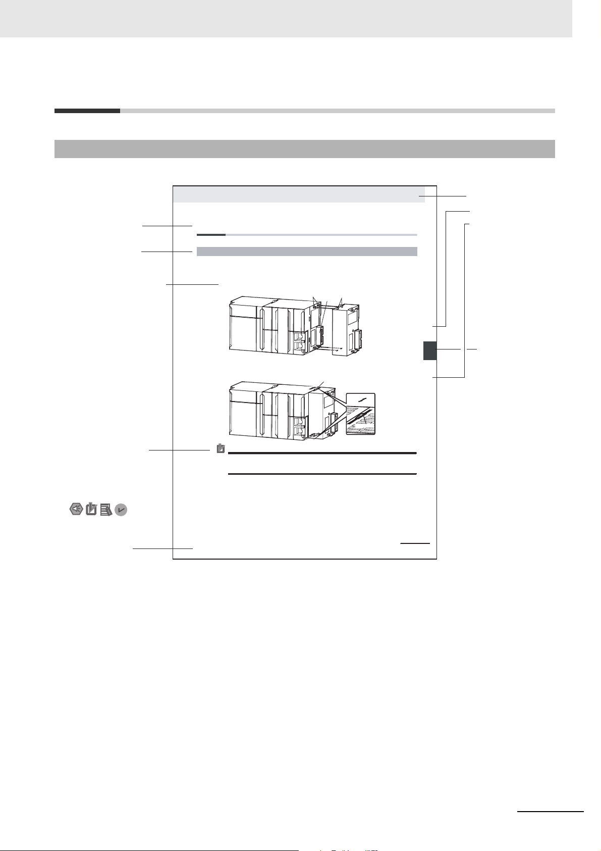
Manual Structure
4-9
4 Installation and Wiring
NJ-series CPU Unit Hardware User’s Manual (W500)
stinU gnitnuoM 3-4
4
stnenopmoC rellortnoC gnitcennoC 1-3-4
4-3 Mounting Units
The Units that make up an NJ-series Controller can be connected simply by pressing the Units together
and locki ng the slide rs by moving them toward the back of the U nits. The End Cover is connecte d in the
same way to the Unit on the far right side of the Controller.
1 Join the Units so that the connectors fit exactly.
2 The yellow sliders at the top and bottom of each Unit lock the Units together. Move the sliders
toward the back of the Units as shown below until they click into place.
Precautions for Correct UsePrecautions for Correct Use
£
4-3-1 Connecting Controller Components
Connector
Hook
Hook holes
Slider
Lock
Release
Move the sliders toward the back
until they lock into place.
Level 1 heading
Level 2 heading
Level 3 heading
Level 2 heading
A step in a procedure
Manual name
Special information
Level 3 heading
Page tab
Gives the current
headings.
Indicates a procedure.
Icons indicate
precautions, additional
information, or reference
information.
Gives the number
of the main section.
This illustration is provided only as a sample. It may not literally appear in this manual.
The sliders on the tops and bottoms of the Power Supply Unit, CPU Unit, I/O Units, Special I/O
Units, and CPU Bus Units must be completely locked (until they click into place) after connecting
the adjacent Unit connectors.
Page Structure and Icons
The following page structure is used in this manual.
Manual Structure
CJ-series EtherCAT Slave Units Operation Manual (W541)
7
Page 10

Manual Structure
Precautions for Safe Use
Precautions for Correct Use
Additional Information
Version Information
Special Information
Special information in this manual is classified as follows:
Precautions on what to do and what not to do to ensure safe usage of the product.
Precautions on what to do and what not to do to ensure proper operation and performance.
Additional information to read as required.
This information is provided to increase understanding or make operation easier.
Information on the differences in specifications and functionality for CPU Units and EtherCAT
Slave Units with different unit versions and for different versions of the CX-Programmer is
given.
Note References are provided to more detailed or related information.
Precautions on Terminology
• In this manual, “download” refers to transferring data from the CX-Programmer to the physical PLC
and “upload” refers to transferring data from the physical PLC to the CX-Programmer.
• The CJ-series EtherCAT Slave Unit can connect with the CJ-series CPU Unit, CP-series CPU Unit
and the NSJ-series CPU Unit. In this manual, the CJ-series CPU Unit is used as an example.
8
CJ-series EtherCAT Slave Units Operation Manual (W541)
Page 11

Terms and Conditions Agreement
Terms and Conditions Agreement
Warranty, Limitations of Liability
Warranties
Exclusive Warranty
Omron’s exclusive warranty is that the Products will be free from defects in materials and workmanship for a period of twelve months from the date of sale by Omron (or such other period expressed in
writing by Omron). Omron disclaims all other warranties, express or implied.
Limitations
OMRON MAKES NO WARRANTY OR REPRESENTATION, EXPRESS OR IMPLIED, ABOUT
NON-INFRINGEMENT, MERCHANTABILITY OR FITNESS FOR A PARTICULAR PURPOSE OF
THE PRODUCTS. BUYER ACKNOWLEDGES THAT IT ALONE HAS DETERMINED THAT THE
PRODUCTS WILL SUITABLY MEET THE REQUIREMENTS OF THEIR INTENDED USE.
Omron further disclaims all warranties and responsibility of any type for claims or expenses based
on infringement by the Products or otherwise of any intellectual property right.
Buyer Remedy
Omron’s sole obligation hereunder shall be, at Omron’s election, to (i) replace (in the form originally
shipped with Buyer responsible for labor charges for removal or replacement thereof) the non-complying Product, (ii) repair the non-complying Product, or (iii) repay or credit Buyer an amount equal
to the purchase price of the non-complying Product; provided that in no event shall Omron be
responsible for warranty, repair, indemnity or any other claims or expenses regarding the Products
unless Omron’s analysis confirms that the Products were properly handled, stored, installed and
maintained and not subject to contamination, abuse, misuse or inappropriate modification. Return of
any Products by Buyer must be approved in writing by Omron before shipment. Omron Companies
shall not be liable for the suitability or unsuitability or the results from the use of Products in combination with any electrical or electronic components, circuits, system assemblies or any other materials or substances or environments. Any advice, recommendations or information given orally or in
writing, are not to be construed as an amendment or addition to the above warranty.
See http://www.omron.com/global/ or contact your Omron representative for published information.
Limitation on Liability; Etc
OMRON COMPANIES SHALL NOT BE LIABLE FOR SPECIAL, INDIRECT, INCIDENTAL, OR CONSEQUENTIAL DAMAGES, LOSS OF PROFITS OR PRODUCTION OR COMMERCIAL LOSS IN ANY
WAY CONNECTED WITH THE PRODUCTS, WHETHER SUCH CLAIM IS BASED IN CONTRACT,
WARRANTY, NEGLIGENCE OR STRICT LIABILITY.
Further, in no event shall liability of Omron Companies exceed the individual price of the Product on
which liability is asserted.
CJ-series EtherCAT Slave Units Operation Manual (W541)
9
Page 12

Terms and Conditions Agreement
Application Considerations
Suitability of Use
Omron Companies shall not be responsible for conformity with any standards, codes or regulations
which apply to the combination of the Product in the Buyer’s application or use of the Product. At
Buyer’s request, Omron will provide applicable third party certification documents identifying ratings
and limitations of use which apply to the Product. This information by itself is not sufficient for a complete determination of the suitability of the Product in combination with the end product, machine, system, or other application or use. Buyer shall be solely responsible for determining appropriateness of
the particular Product with respect to Buyer’s application, product or system. Buyer shall take application responsibility in all cases.
NEVER USE THE PRODUCT FOR AN APPLICATION INVOLVING SERIOUS RISK TO LIFE OR
PROPERTY OR IN LARGE QUANTITIES WITHOUT ENSURING THAT THE SYSTEM AS A WHOLE
HAS BEEN DESIGNED TO ADDRESS THE RISKS, AND THAT THE OMRON PRODUCT(S) IS
PROPERLY RATED AND INSTALLED FOR THE INTENDED USE WITHIN THE OVERALL EQUIPMENT OR SYSTEM.
Programmable Products
Omron Companies shall not be responsible for the user’s programming of a programmable Product, or
any consequence thereof.
Disclaimers
Performance Data
Data presented in Omron Company websites, catalogs and other materials is provided as a guide for
the user in determining suitability and does not constitute a warranty. It may represent the result of
Omron’s test conditions, and the user must correlate it to actual application requirements. Actual performance is subject to the Omron’s Warranty and Limitations of Liability.
Change in Specifications
Product specifications and accessories may be changed at any time based on improvements and other
reasons. It is our practice to change part numbers when published ratings or features are changed, or
when significant construction changes are made. However, some specifications of the Product may be
changed without any notice. When in doubt, special part numbers may be assigned to fix or establish
key specifications for your application. Please consult with your Omron’s representative at any time to
confirm actual specifications of purchased Product.
10
Errors and Omissions
Information presented by Omron Companies has been checked and is believed to be accurate; however, no responsibility is assumed for clerical, typographical or proofreading errors or omissions.
CJ-series EtherCAT Slave Units Operation Manual (W541)
Page 13
Safety Precautions
Definition of Precautionary Information
The following notation is used in this manual to provide precautions required to ensure safe usage of
EtherCAT Slave Unit.
The safety precautions that are provided are extremely important to safety. Always read and heed the
information provided in all safety precautions.
The following notation is used.
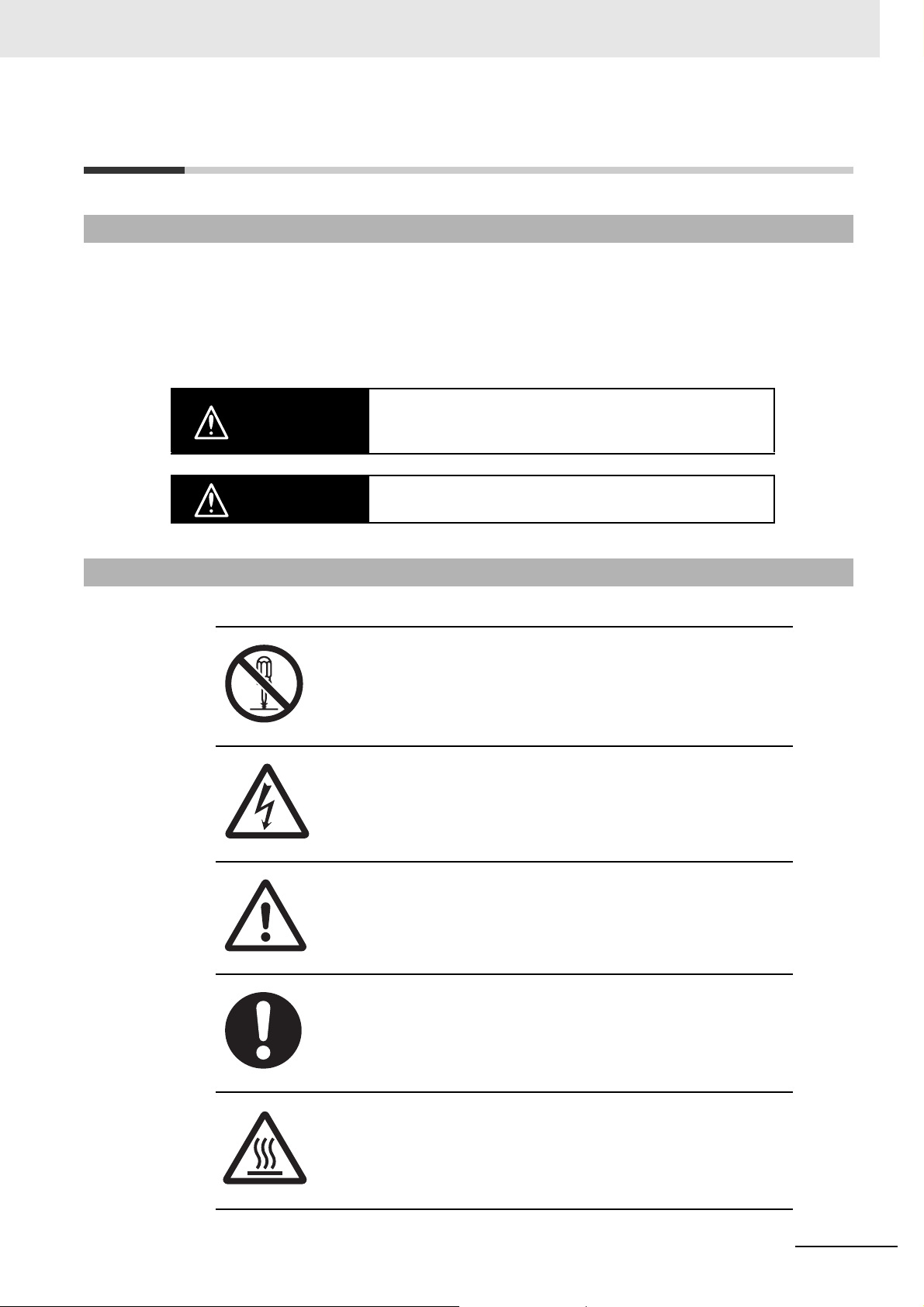
Indicates a potentially hazardous situation which, if not avoided,
WARNING
could result in death or serious injury. Additionally, there may be
severe property damage.
Safety Precautions
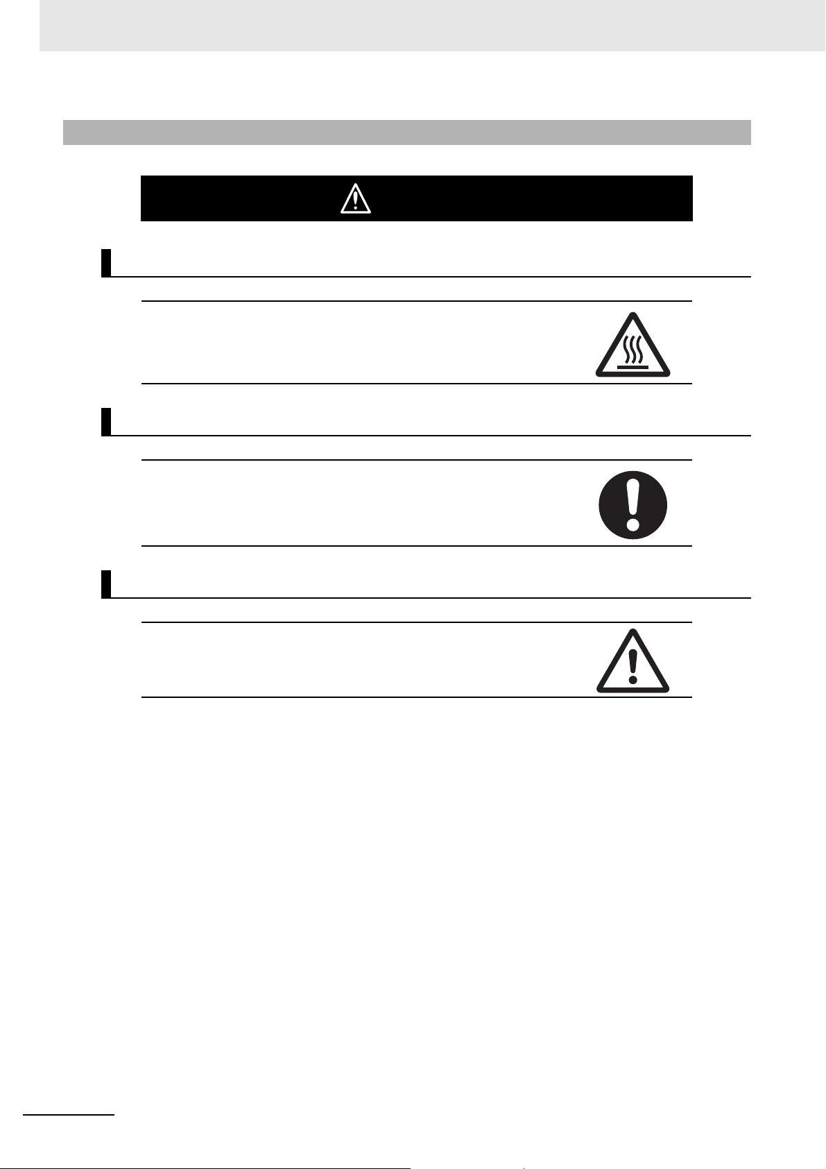
Symbols
Caution
Indicates a potentially hazardous situation which, if not avoided,
may result in minor or moderate injury, or property damage.
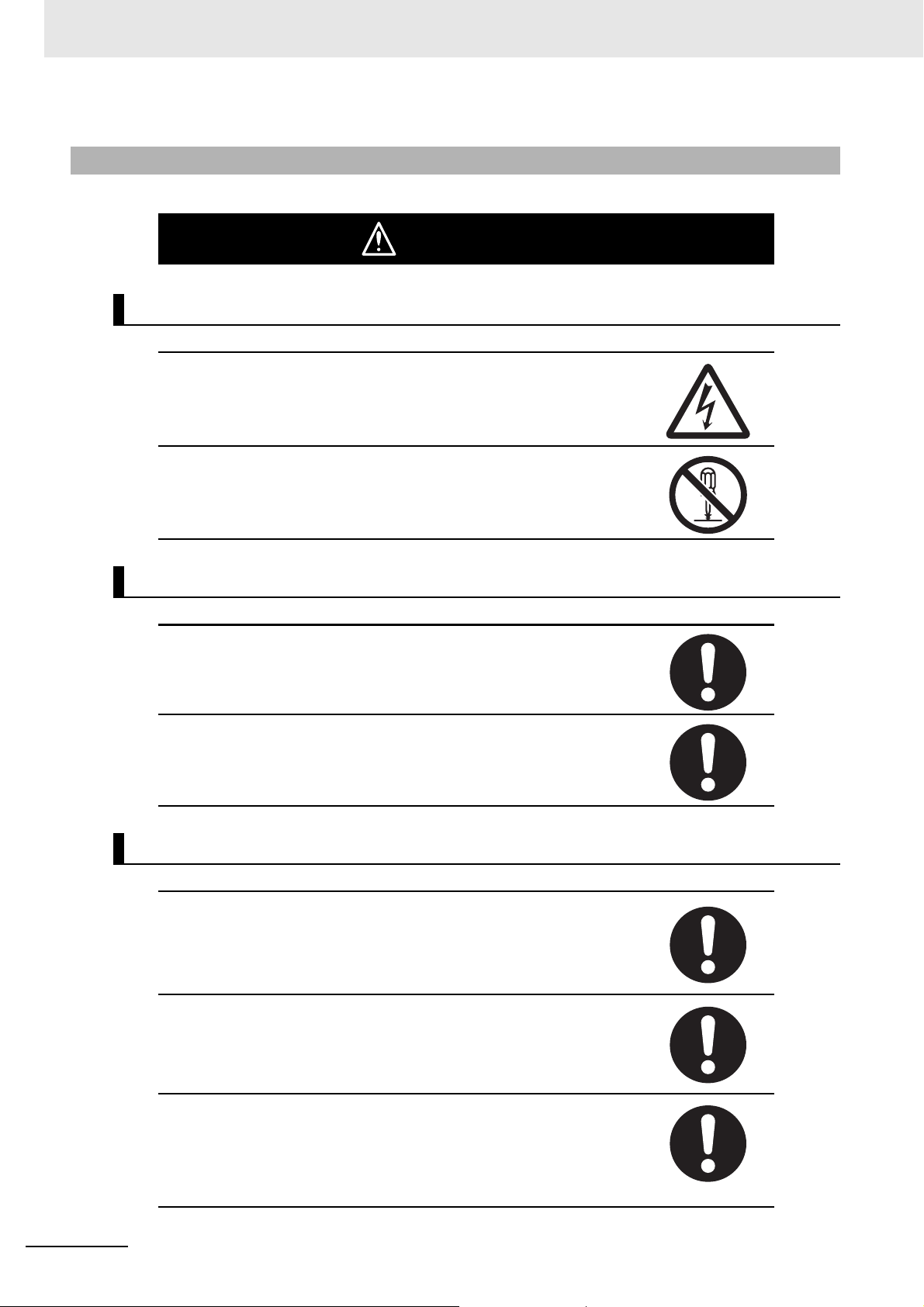
The circle and slash symbol indicates operations that you must not do.
The specific operation is shown in the circle and explained in text.
This example indicates prohibiting disassembly.
The triangle symbol indicates precautions (including warnings).
The specific operation is shown in the triangle and explained in text.
This example indicates a precaution for electric shock.
The triangle symbol indicates precautions (including warnings).
The specific operation is shown in the triangle and explained in text.
This example indicates a general precaution.
The filled circle symbol indicates operations that you must do.
The specific operation is shown in the circle and explained in text.
This example shows a general precaution for something that you must do.
The triangle symbol indicates precautions (including warnings).
The specific operation is shown in the triangle and explained in text.
This example indicates the precaution for high temperatures.
CJ-series EtherCAT Slave Units Operation Manual (W541)
11
Page 14
Safety Precautions
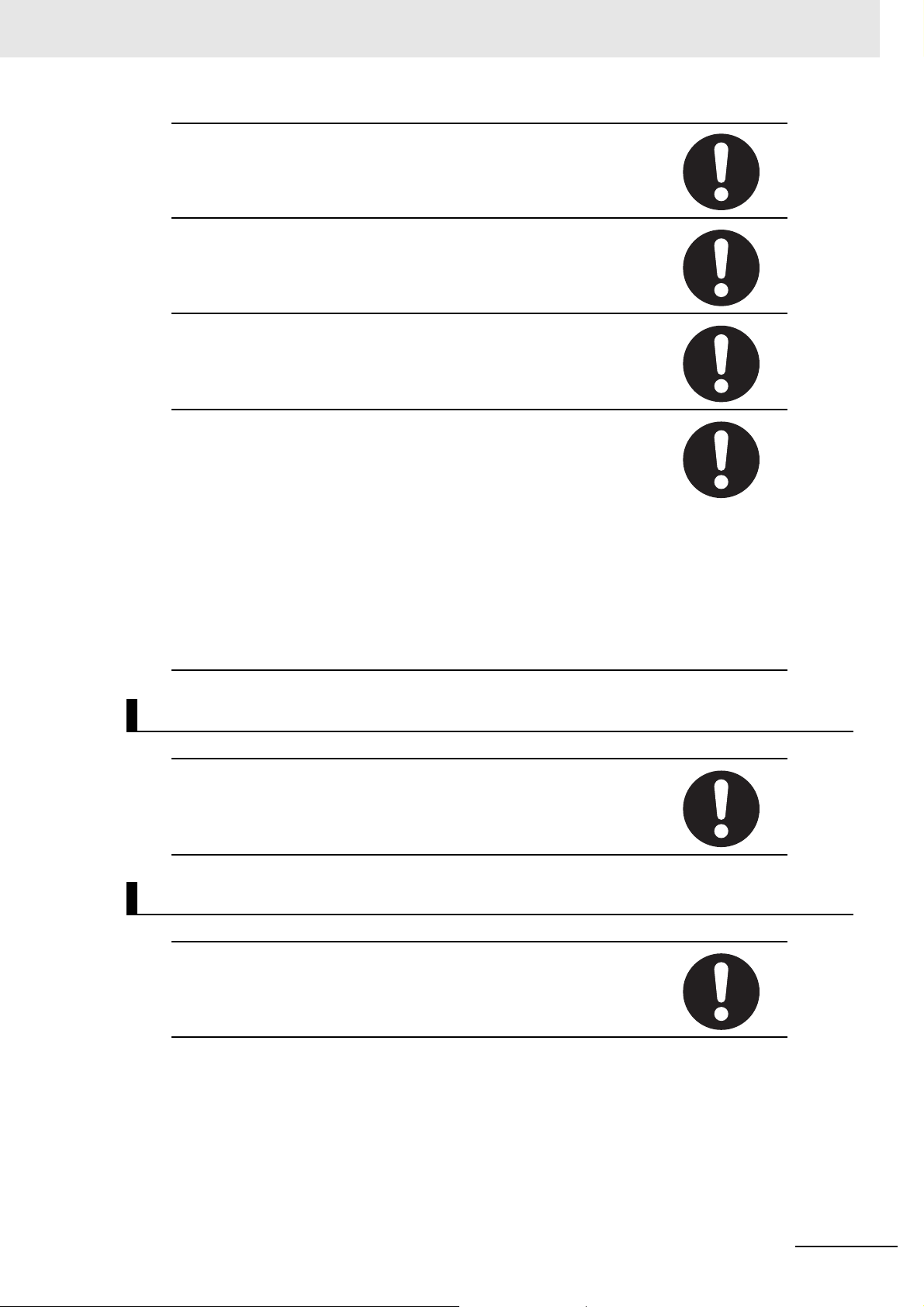
Warnings
During Power Supply
Do not touch any of the terminals or terminal blocks while the power is being
supplied. Doing so may result in electric shock.
Do not attempt to take any Unit apart. In particular, high-voltage parts are
present in the Power Supply Unit while power is supplied or immediately
after power is turned OFF. Touching any of these parts may result in electric
shock. There are sharp parts inside the Unit that may cause injury.
WARNING
Transferring
Always confirm safety at the destination node before transferring a program
to another node or changing contents of the I/O memory area. Doing either
of these without confirming safety may result in injury.
Confirm safety before transferring data files stored in the file memory (Memory Card or EM file memory) to the I/O area (CIO) of the CPU Unit using a
programming device. Otherwise, the devices connected to the output Unit
may malfunction regardless of the operation mode of the CPU Unit.
Fail-safe Measures
Provide safety measures in external circuits (i.e., not in the Programmable
Controller), including the following items, to ensure safety in the system if an
abnormality occurs due to malfunction of the PLC or another external factor
affecting the PLC operation. Not doing so may result in serious accidents.
Unintended outputs may occur when an error occurs in memory used for
CJ-series Units. As a countermeasure for such problems, external safety
measures must be provided to ensure safe operation of the system.
Emergency stop circuits, interlock circuits, limit circuits, and similar safety
measures must be provided in external control circuits.
The PLC will turn OFF all outputs when its self-diagnosis function detects
any error or when a severe failure alarm (FALS) instruction is executed.
Unexpected operation, however, may still occur for errors in the I/O control
section, errors in I/O memory, and other errors that cannot be detected by
the self-diagnosis function. As a countermeasure for all such errors, external
safety measures must be provided to ensure safety in the system.
12
CJ-series EtherCAT Slave Units Operation Manual (W541)
Page 15
The Controller outputs may remain ON or OFF due to deposition or burning
of the output relays or destruction of the output transistors.
As a countermeasure for such problems, external safety measures must be
provided to ensure safe operation of the system.
When the 24-V DC output (service power supply to the PLC) is overloaded or
short-circuited, the voltage may drop and result in the outputs being turned
OFF. As a countermeasure for such problems, external safety measures
must be provided to ensure safety in the system.
Fail-safe measures must be taken by the customer to ensure safety in the
event of incorrect, missing, or abnormal signals caused by broken signal
lines, momentary power interruptions, or other causes. Serious accidents
may result from abnormal operation if proper measures are not provided.
The CPU Unit refreshes I/O even when the program is stopped (i.e., even in
PROGRAM mode). Confirm safety thoroughly in advance before changing
the status of any part of memory allocated to I/O Units, Special I/O Units, or
CPU Bus Units. Any changes to the data allocated to any Unit may result in
unexpected operation of the loads connected to the Unit. Any of the following
operation may result in changes to memory status.
• Transferring I/O memory data to the CPU Unit from a programming device.
• Changing present values in memory from a programming device.
• Force-setting/-resetting bits from a programming device.
• Transferring I/O memory files from a Memory Card or EM file memory to
the CPU Unit.
• Transferring I/O memory from a host computer or from another PLC on a
network.
Safety Precautions
Actual Operation
Check the user program, data, and parameter settings for proper execution
before you use them for actual operation.
Voltage and Current Inputs
Make sure that the voltages and currents that are input to the Units and
slaves are within the specified ranges.
Inputting voltages or currents that are outside of the specified ranges may
cause accidents or fire.
CJ-series EtherCAT Slave Units Operation Manual (W541)
13
Page 16
Safety Precautions
Cautions
Application
Do not touch any Unit when power is being supplied or immediately after the
power supply is turned OFF. Doing so may result in burn injury.
Wiring
Caution
Be sure that all terminal screws and cable connector screws are tightened to
the torque specified in the relevant manuals. The loose screws may result in
fire or malfunction.
Online Editing
Execute online edit only after confirming that no adverse effects will be
caused by extending the cycle time. Otherwise, the input signals may not be
readable.
14
CJ-series EtherCAT Slave Units Operation Manual (W541)
Page 17

Precautions for Safe Use
Disassembly and Dropping
• Do not attempt to disassemble, repair, or modify any Units. Doing so may result in malfunction, fire or
electric shock.
• Do not drop any Unit or subject it to abnormal vibration or shock. Doing so may result in Unit malfunctioning or burning.
Mounting
• After connecting Power Supply Units, CPU Units, I/O Units, Special I/O Units, or CPU Bus Units
together, secure the Units by sliding the sliders at the top and bottom of the Units until they click into
place. Correct operation may not be possible if the Units are not securely properly.
• Be sure to attach the end cover provided with the CPU Unit to the right-most Unit. CJ-series PLCs
will not operate properly if the end cover is not attached.
Precautions for Safe Use
Transporting
• When transporting the Unit, use special packing boxes and protect it from being exposed to excessive vibration or impact during transportation.
Installation
• Always connect to a ground of 100 Ω or less when installing the Units. A ground of 100 Ω or less
must be installed when shorting the GR and LG terminals on the Power Supply Unit.
Wiring
• Follow the instructions in this manual to correctly perform wiring.
Double-check all wiring and switch settings before turning ON the power supply. Incorrect wiring may
result in burning.
• Use parts and tools appropriate for wiring.
• Do not pull on the cables or bend the cables beyond their natural limit.
Do not place heavy objects on top of the cables or other wiring lines. Doing so may break the cables.
• Mount terminal blocks and connectors only after checking the mounting location carefully.
Be sure that the terminal blocks, Memory Units, expansion cables, and other items with locking
devices are properly locked into place. Improper locking may result in malfunction.
• Before you connect a computer to the PLC, disconnect the power supply plug of the computer from
the AC outlet. Also, if the computer has an FG terminal, make the connections so that the FG terminal has the same electrical potential as the FG (GR) terminal on the Power Supply Unit. A difference
in electric potential between the computer and PLC may cause failure or malfunction.
• Use crimp terminals for wiring. Do not connect bare stranded wires directly to terminals. Connection
of bare stranded wires may result in burning.
CJ-series EtherCAT Slave Units Operation Manual (W541)
15
Page 18

Precautions for Safe Use
Power Supply Design
• Do not exceed the rated supply capacity of the Power Supply Units in the CJ-series PLC. The rated
supply capacities are given in the operation manual of the CPU Units.
If the capacity is exceeded, operation may stop, malfunctions may occur, or data may not be backed
up normally for power interruptions.
Use CJ-series Power Supply Units for both the CJ-series CPU Rack and Expansion Racks.
Operation is not possible if an NJ/NX-series Power Supply Unit is used with a CJ-series CPU Unit.
• Surge current occurs when the power supply is turned ON. When selecting fuses or breakers for
external circuits, consider the above precaution and allow sufficient margin in shut-off performance.
Refer to the relevant manuals for surge current specifications. Refer to the operation manual of the
CPU Units for surge current specifications.
• If the full dielectric strength voltage is applied or turned OFF using the switch on the tester, the generated impulse voltage may damage the Power Supply Unit. Use the adjustment on the tester to gradually increase and decrease the voltage.
• Apply the voltage between the Power Supply Unit's L1 or L2 terminal and the GR terminal when testing insulation and dielectric strength.
• Do not supply AC power from an inverter or other device with a square-wave output. Internal temperature rise may result in smoking or burning. Always input a sinusoidal wave with the frequency that is
given in the operation manual of the CPU Units.
• Install external breakers and take other safety measures against short-circuiting in external wiring.
Turning ON the Power Supply
• Always turn ON power to the PLC before turning ON power to the control system. If the PLC power
supply is turned ON after the control power supply, temporary errors may result in control system signals because the output terminals on DC Output Units and other Units may momentarily turn ON
when power is turned ON to the PLC.
• Double-check all wiring and switch settings before turning ON the power supply. Incorrect wiring may
result in burning.
Actual Operation
• Check the user program, data, and parameter settings for proper execution before you use them for
actual operation.
• Confirm that the I/O Communication Area Setting Table and I/O Reference Area Setting Table settings are correct. Incorrect system settings can cause unexpected behavior.
Turning OFF the Power Supply
• Do not disconnect the cable or turn OFF the power supply to the PLC when downloading data or the
user program from Support Software.
• Always turn OFF the power supply to the PLC before attempting any of the following.
a) Mounting or removing I/O Units or the CPU Unit
b) Assembling the Units
c) Setting DIP switches or rotary switches
d) Connecting cables or wiring the system
e) Connecting or disconnecting the connectors
• Do not touch the terminals on the Power Supply Unit immediately after turning OFF the power supply.
Residual voltage may cause electrical shock.
16
CJ-series EtherCAT Slave Units Operation Manual (W541)
Page 19

Precautions for Safe Use
Operation
• Confirm that no adverse effect will occur in the system before you attempt any of the following.
a) Changing the operating mode of the CPU Unit (including changing the setting of the Operating
Mode at Startup)
b) Changing the user program or settings
c) Changing set values or present values
d) Forced refreshing
• After you change any slave or Unit settings, carefully check the safety of the controlled system before
you restart the Unit.
EtherCAT Communications
• Make sure that the communications distance, number of nodes connected, and method of connection for EtherCAT are within specifications.
• Do not connect EtherCAT communications to EtherNet/IP, a standard in-house LAN, or other networks. An overload may cause the network to fail or malfunction.
• The maximum length between nodes is 100 m. However, some cables are specified for less than 100
m. Generally speaking, if the conductors are twisted wire rather than solid wire, transmission performance will be lower, and reliable communications may not be possible at 100 m. Confirm details with
the cable manufacturer.
• If noise occurs or an EtherCAT slave is disconnected from the network, any current communications
frames may be lost. If frames are lost, slave I/O data is not communicated, and unintended operation
may occur. The slave outputs will behave according to the slave specifications. Confirm that the system will not be adversely affected before you disconnect a slave.
• When an EtherCAT slave is disconnected or disabled, communications will stop and control of the
outputs will be lost not only for the disconnected slave, but for all slaves connected after it. Confirm
that the system will not be adversely affected before you disconnect or disable a slave.
Unit Replacement
• When replacing parts, be sure to confirm that the rating of a new part is correct. Not doing so may
result in malfunction or burning.
• After replacing Units, resume operation only after transferring to the new CPU Unit and/or Special I/O
Units the contents of the DM Area, HR Area, and other data required for resuming operation. Not
doing so may result in unexpected operation.
• If you replace a CPU Bus Unit or Special I/O Unit, refer to operation manual for the Unit for information on the data required for individual Units and redo the necessary settings.
Disposal
• Dispose of the product according to local ordinances as they apply.
CJ-series EtherCAT Slave Units Operation Manual (W541)
17
Page 20

Precautions for Correct Use
Precautions for Correct Use
Storage, Mounting, and Wiring
• Do not operate the control system in the following locations. Operation may stop or malfunctions may
occur.
a) Locations subject to direct sunlight
b) Locations subject to temperatures or humidity outside the range specified in the specifications
c) Locations subject to condensation as the result of severe changes in temperature
d) Locations subject to corrosive or flammable gases
e) Locations subject to dust (especially iron dust) or salts
f) Locations subject to exposure to water, oil or chemicals
g) Locations subject to shock or vibration
• Take appropriate and sufficient countermeasures when installing the Controller in the following locations.
a) Locations subject to static electricity or other forms of noise
b) Locations subject to strong electromagnetic fields
c) Locations subject to possible exposure to radioactivity
d) Locations close to power lines
• Before touching a Unit, be sure to first touch a grounded metallic object in order to discharge any
static build-up.
• Use the rated power supply voltage for the Power Supply Units. Take appropriate measures to
ensure that the specified power with the rated voltage and frequency is supplied in places where the
power supply is unstable.
• Install the control system away from sources of heat and ensure proper ventilation. Not doing so may
result in malfunction, in operation stopping, or in burning.
• Use proper connection methods and EtherCAT communication cables. Otherwise, communications
may be faulty. Refer to 2-3 EtherCAT Network Wiring on page 2-10.
• Do not allow foreign matter to enter the openings in the Unit. Doing so may result in Unit burning,
electric shock, or failure.
• Do not allow wire clippings, shavings, or other foreign material to enter any Unit. Otherwise, Unit
burning, failure, or malfunction may occur. Cover the Units or take other suitable countermeasures,
especially during wiring work.
18
EtherCAT Communications
• Do not disconnect the EtherCAT slave cables during operation. The outputs will become unstable.
Operating Environment
• The operating environment of the PLC System can have a large effect on the longevity and reliability
of the system. Improper operating environments can lead to malfunction, failure, and other unforeseeable problems with the PLC System. Be sure that the operating environment is within the specified conditions at installation and remains within the specified conditions during the life of the system.
CJ-series EtherCAT Slave Units Operation Manual (W541)
Page 21

Regulations and Standards
Conformance to EC Directives
Applicable Directives
• EMC Directives
• Low Voltage Directive
Concepts
EMC Directive
OMRON devices that comply with EC Directives also conform to the related EMC standards so that
they can be more easily built into other devices or the overall machine. The actual products have
been checked for conformity to EMC standards.
*1
Regulations and Standards
Whether the products conform to the standards in the system used by the customer, however, must
be checked by the customer. EMC-related performance of the OMRON devices that comply with EC
Directives will vary depending on the configuration, wiring, and other conditions of the equipment or
control panel on which the OMRON devices are installed. The customer must, therefore, perform
the final check to confirm that devices and the overall machine conform to EMC standards.
*1. Applicable EMC (Electromagnetic Compatibility) standards are as follows:
EMS (Electromagnetic Susceptibility): EN 61131-2
EMI (Electromagnetic Interference): EN 61131-2 (Radiated emission: 10-m regulations)
Low Voltage Directive
Always ensure that devices operating at voltages of 50 to 1,000 VAC and 75 to 1,500 VDC meet the
required safety standards. The applicable directive is EN 61131-2.
Conformance to EC Directives
The CJ-series PLCs comply with EC Directives. To ensure that the machine or device in which the
CJ-series PLC is used complies with EC Directives, the PLC must be installed as follows:
• The CJ-series PLC must be installed within a control panel.
• You must use reinforced insulation or double insulation for the DC power supplies used for the
communications power supply and I/O power supplies.
• CJ-series PLCs complying with EC Directives also conform to the Common Emission Standard
(EN 61000-6-4). Radiated emission characteristics (10-m regulations) may vary depending on the
configuration of the control panel used, other devices connected to the control panel, wiring, and
other conditions. You must therefore confirm that the overall machine or equipment complies with
EC Directives.
Conformance to UL and CSA Standards
Some CJ-series PLCs comply with UL and CSA standards. Refer to the OMRON website
(http://www.ia.omron.com/) or consult your OMRON representative for the applicable standards for
each model. The Instruction Sheet is provided with the product depending on the models. The Instruc-
tion Sheet provides the application conditions for complying with the standards.
CJ-series EtherCAT Slave Units Operation Manual (W541)
19
Page 22
Regulations and Standards
Conformance to Shipbuilding Standards
Some CJ-series PLCs comply with shipbuilding standards. Refer to the OMRON website
(http://www.ia.omron.com/) or consult your OMRON representative for the applicable standards for
each model. If you use a CJ-series product that complies with shipbuilding standards and the machinery or system in which you use the CJ-series products must also comply with the standards, consult
with your OMRON representative. Application conditions are defined according to the installation location. Application may not be possible for some installation locations.
Usage Conditions for NK and LR Shipbuilding Standards
• The CJ-series PLC must be installed within a control panel.
• Gaps in the door to the control panel must be completely filled or covered with gaskets or other material.
• The following noise filter must be connected to the power supply line.
Name Manufacturer Model
Noise filter Cosel Co., Ltd. TAH-06-683
Conformance to KC Standards
Observe the following precaution if you use CJ-series CJ1W-ECT21 EtherCAT Slave Units in Korea.
Class A Device (Broadcasting Communications Device for Office Use)
This device obtained EMC registration for office use (Class A), and it is intended to be used in places
other than homes.
Sellers and/or users need to take note of this.
20
CJ-series EtherCAT Slave Units Operation Manual (W541)
Page 23
Unit Versions
Precautions for Correct Use
CJ1W-
UNIT
Lot No. YYMMDD xxxx Ver.1.0
OMRON Corporation
MADE IN JAPAN
Product nameplate
Unit version
Example for unit version 1.0
Lot No.
Unit model
Serial No.
Unit Versions
A “unit version” has been introduced to manage CPU Units in the CJ Series according to differences in
functionality accompanying Unit upgrades.
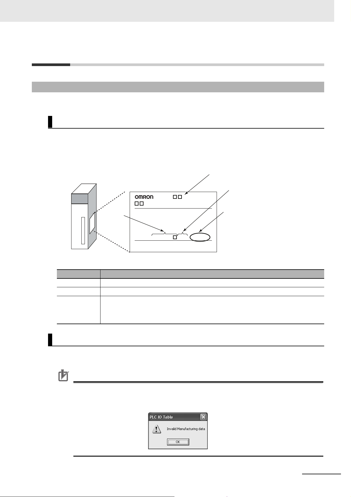
Notation of Unit Versions on Products
The Unit version is given to the right of the lot number on the nameplate of the products for which unit
versions are being managed, as shown below.
Example of a CJ-series Unit:
Unit Versions
The following information is provided on the ID information label.
Item Description
Unit model Gives the model of the Unit.
Unit version Gives the unit version of the Unit.
Lot number and
serial number
Gives the lot number and serial number of the Unit.
• YYMMDD: Lot number (
• xxxx: Serial number
: For use by OMRON)
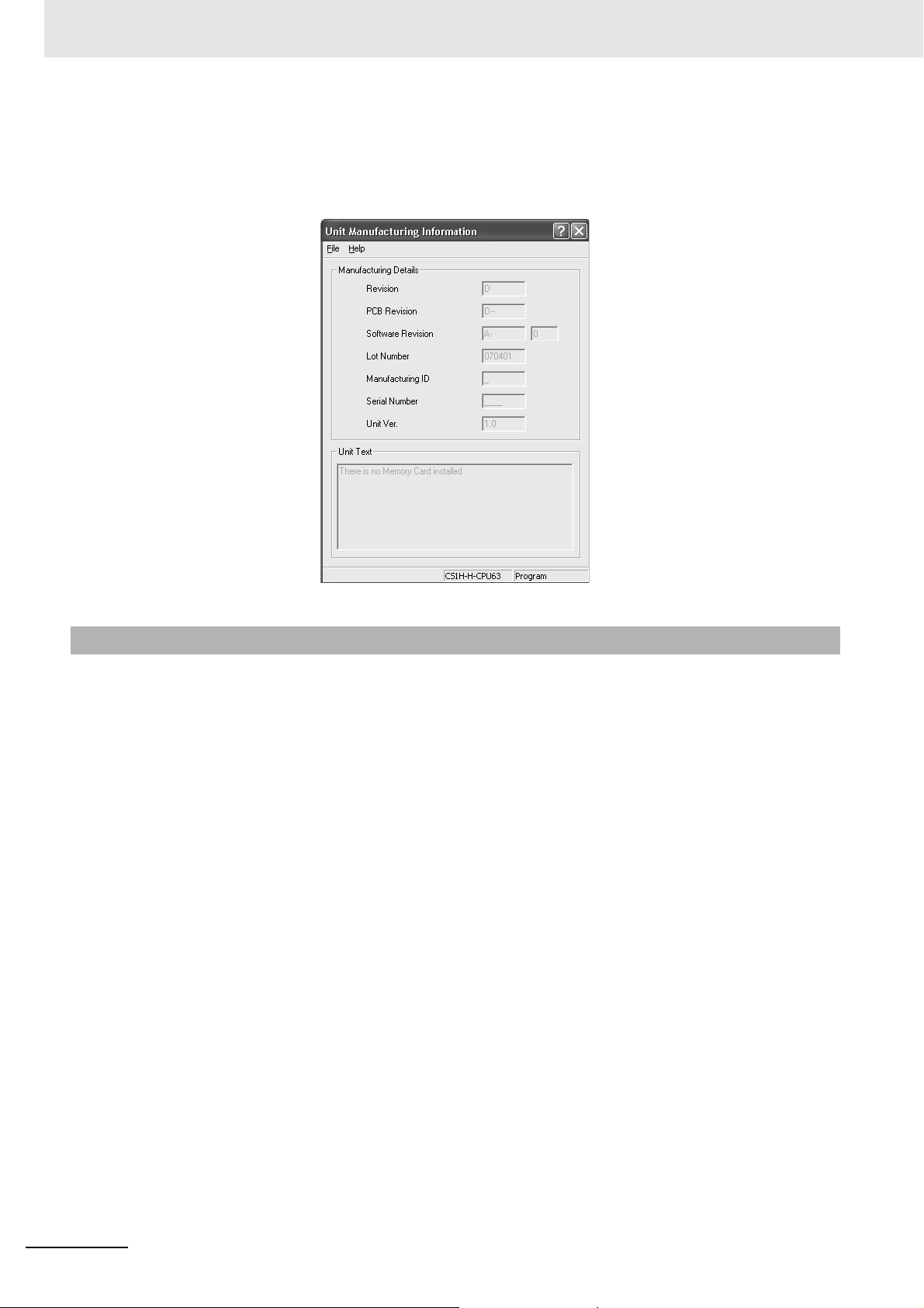
Confirming Unit Versions with Support Software
CX-Programmer version 4.0 can be used to confirm the unit version using the Unit Manufacturing
Information.
The unit versions of Pre-Ver.1.0 Units cannot be confirmed in Unit Manufacturing Information.
The following dialog box is displayed.
CJ-series EtherCAT Slave Units Operation Manual (W541)
21
Page 24
Unit Versions
In the IO Table Window, right-click the Unit to check the Unit Version and select Unit Manufacturing
Information.
The following Unit Manufacturing Information Dialog Box will be displayed.
Unit Versions and CX-Programmer Versions
The functions that are supported depend on the unit version of the Unit. The version of CX-Programmer
that supports the functions that were added for an upgrade is also required to use those functions.
Refer to A-7 Version Information on page A-33 for the functions that are supported by each version.
22
CJ-series EtherCAT Slave Units Operation Manual (W541)
Page 25

Related Manuals
The following manuals are related. Use these manuals for reference.
Manual name Cat. No. Model numbers Application Description
CJ-series EtherCAT®
Slave Units Operation
Manual
CX-Programmer Operational Manual
SYSMAC CJ Series Programmable Controllers
Operation Manual
SYSMAC CJ Series CJ2
CPU Unit Software
User’s Manual
SYSMAC CJ Series CJ2
CPU Unit Hardware
User’s Manual
SYSMAC ONE NSJ
Series Controllers Operation Manual
SYSMAC CP Series
CP1H CPU Unit Operation Manual
W541 CJ1W-ECT21 Learning how to use an
EtherCAT Slave Unit.
W446 CXONE-ALC-V4
W393 CJ1G-CPU
W473 CJ2H-CPU6-EIP
W472 CJ2H-CPU6-EIP
W452 NSJ5-TQ(B)-G5D
W450 CP1H-X40D-
CXONE-ALD-V4
CJ1M-CPU
CJ1G-CPUP
CJ1G/H-CPUH
CJ2H-CPU6
CJ2M-CPU
CJ2H-CPU6
CJ2M-CPU
NSJ5-SQ(B)-G5D
NSJ8-TV(B)-G5D
NSJ10-TV(B)-G5D
NSJ12-TS
NSJ5-TQ
NSJ5-SQ(B)-M3D
NSJ8-TV(B)-M3D
NSJW-ETN21
NSJW-CLK21-V1
NSJW-IC101
CP1H-XA40D-
CP1H-Y20DT-D
(B)-
(B)-M3D
G5D
Learning the functions and
application methods of the
CX-Programmer software.
Learning the functions and
application methods of the
CJ Series PLC.
Learning the functions and
application methods of the
CJ2 Series PLC Software.
Learning the functions and
application methods of the
CJ2 Series PLC Hardware.
Learning the functions and
application methods of the
NSJ Series Controller.
Learning the functions and
application methods of the
CP1H Series Controller.
The following items are described: the
overall system and configuration methods of an EtherCAT Slave Unit, information on hardware and functions to set up,
control and monitor the EtherCAT Slave
Unit.
Provides information on how to use the
CX-Programmer for all functionality
except for function blocks.
Provides an outline of, and describes the
design, installation, maintenance, and
other basic operations for the CJ-series
PLCs.
Describes the following for CJ2 CPU
Units:
• CPU Unit operation
• Internal memory
• Programming
• Settings
• Function built into the CPU Unit
Use together with the SYSMAC CJ
Series CJ2 CPU Unit Hardware User’s
Manual (W472).
Describes the following for CJ2 CPU
Units:
• Overview and features
• Basic system configuration
• Part nomenclature and functions
• Mounting and setting procedure
• Remedies for errors
Use together with the SYSMAC CJ
Series CJ2 CPU Unit Software User’s
Manual (W473).
Provides basic specifications on NSJ
Controllers, including an overview,
designing, installation, and maintenance.
Provides basic specifications on
CP-series CP1H PLCs, including an
overview, designing, installation, and
maintenance.
Related Manuals
CJ-series EtherCAT Slave Units Operation Manual (W541)
23
Page 26

Related Manuals
Manual name Cat. No. Model numbers Application Description
NJ/NX-series CPU Unit
Software User’s Manual
Sysmac Studio Version 1
Operation Manual
NJ/NX-series CPU Unit
Built-in EtherCAT® Port
User’s Manual
W501
W504
W505
NX701-
NJ501-
NJ301-
NJ101-
SYSMAC-SE2
NX701-
NJ501-
NJ301-
NJ101-
Learning how to program
and set up an
NJ/NX-series CPU Unit.
Mainly software information is provided.
Learning about the operating procedures and functions of the Sysmac Studio.
Using the built-in EtherCAT
port on an NJ/NX-series
CPU Unit.
The following information is provided on
an NJ/NX-series CPU Unit.
• CPU Unit operation
• CPU Unit features
• Initial settings
• Programming based on IEC 61131-3
language specifications
Use this manual together with the
NX-series CPU Unit Hardware User’s
Manual (Cat. No. W535) or the NJ-series
CPU Unit Hardware User’s Manual (Cat.
No. W500).
Describes the operating procedures of
the Sysmac Studio.
Information on the built-in EtherCAT port
is provided.
This manual provides an introduction and
provides information on the configuration,
features and setup.
Use this manual together with the
NX-series CPU Unit Hardware User’s
Manual (Cat. No. W535) or NJ-series
CPU Unit Hardware User’s Manual (Cat.
No. W500) and with the NJ/NX-series
CPU Unit Software User’s Manual (Cat.
No. W501).
24
CJ-series EtherCAT Slave Units Operation Manual (W541)
Page 27

Terminology
Term Abbreviation Description
application layer status, AL status --- Status for indicating information on errors that occur in
CAN application protocol over EtherCAT
CAN in Automation CiA CiA is the international users' and manufacturers'
device profile --- A collection of device dependent information and func-
device variable --- A variable in the NJ/NX-series CPU Unit to which pro-
EtherCAT slave controller ESC A controller for EtherCAT slave communications.
EtherCAT slave information ESI An XML file that contains setting information for an
EtherCAT state machine ESM An EtherCAT communications state machine.
EtherCAT Technology Group ETG The ETG is a global organization in which OEM, end
I/O map settings --- Settings that assign variables to I/O ports. Assignment
I/O port --- A logical interface that is used by the CPU Unit to
I/O refreshing --- Cyclic data exchange with external devices that is per-
index --- Address of an object within an application process.
network configuration information --- The EtherCAT network configuration information held
object --- An abstract representation of a particular component
object dictionary OD Data structure that contains description of data type
Operational --- A state in EtherCAT communications where SDO com-
PDO communications --- An acronym for process data communications.
Pre-Operational --- A state in EtherCAT communications where only SDO
process data --- Collection of application objects designated to be
process data communications --- One type of EtherCAT communications in which pro-
Terminology
an application on a slave.
CoE A CAN application protocol service implemented on
EtherCAT.
group that develops and supports higher-layer protocols.
tionality providing consistency between similar devices
of the same device type.
cess data on an EtherCAT slave is allocated. Slave
process data is accessed by directly reading and writing device variables from user applications on the
NJ/NX-series CPU Unit.
EtherCAT slave.
users, and technology providers join forces to support
and promote the further technology development.
information between I/O ports and variables.
exchange data with an external device (slave or Unit).
formed with predetermined memory addresses.
by the EtherCAT master.
within a device, which consists of data, parameters,
and methods.
objects, communication objects and application
objects.
munications and I/O are possible.
communications are possible with the slaves, i.e., no
I/O can be performed.
downloaded cyclically or acyclically for the purpose of
measurement and control.
cess data objects (PDOs) are used to exchange information cyclically and in realtime. This is also called
PDO communications.
CJ-series EtherCAT Slave Units Operation Manual (W541)
25
Page 28

Terminology
process data object PDO A structure that describes the mappings of parameters
receive PDO RxPDO A process data object received by an EtherCAT slave.
Safe-Operational --- A state in EtherCAT communications where only SDO
SDO communications --- One type of EtherCAT communications in which ser-
service data object SDO CoE asynchronous mailbox communications where all
Slave Information Interface SII Slave information that is stored in non-volatile memory
subindex --- Sub-address of an object within the object dictionary.
Sync Manager SM Collection of control elements to coordinate access to
task period --- The interval at which the primary periodic task or a
transmit PDO TxPDO A process data object sent from an EtherCAT slave.
Term Abbreviation Description
that have one or more process data entities.
communications and reading input data from slaves
are possible. Outputs from slaves are not performed.
vice data objects (SDOs) are used to transmit information whenever required.
objects in the object dictionary can be read and written.
in the slave.
concurrently used objects.
periodic task is executed.
26
CJ-series EtherCAT Slave Units Operation Manual (W541)
Page 29

Revision History
A manual revision code appears as a suffix to the catalog number on the front and back covers of the
manual.
Revision History
Cat. No.
Revision code Date Revised content
01 April 2015 Original production
02 April 2019 Added information on the unit version that supports a ring
W541-E1-02
Revision code
topology.
CJ-series EtherCAT Slave Units Operation Manual (W541)
27
Page 30

Revision History
28
CJ-series EtherCAT Slave Units Operation Manual (W541)
Page 31

1
2
3
4
5
6
A
I
1
2
3
4
5
6
A
I
Features and System
Configuration
EtherCAT
Communications
Troubleshooting
Appendices
Maintenance and Replacement
Index
Nomenclature and
Installation
Memory Allocations
Sections in this Manual
Sections in this Manual
CJ-series EtherCAT Slave Units Operation Manual (W541)
29
Page 32

Sections in this Manual
30
CJ-series EtherCAT Slave Units Operation Manual (W541)
Page 33

Features and System Configuration
This section provides an introduction to EtherCAT networks and includes features, system configurations, specifications and setting procedures.
1-1 Introduction to EtherCAT . . . . . . . . . . . . . . . . . . . . . . . . . . . . . . . . . . . . . . . 1-2
1-1-1 How EtherCAT Works . . . . . . . . . . . . . . . . . . . . . . . . . . . . . . . . . . . . . . . . . . . . 1-2
1-1-2 Types of EtherCAT Communications . . . . . . . . . . . . . . . . . . . . . . . . . . . . . . . . 1-3
1-2 EtherCAT Slave Unit Features . . . . . . . . . . . . . . . . . . . . . . . . . . . . . . . . . . . 1-5
1-3 System Configuration of CJ-series EtherCAT Slave Unit . . . . . . . . . . . . . 1-7
1-4 Specifications . . . . . . . . . . . . . . . . . . . . . . . . . . . . . . . . . . . . . . . . . . . . . . . . . 1-9
1-4-1 General Specifications . . . . . . . . . . . . . . . . . . . . . . . . . . . . . . . . . . . . . . . . . . . 1-9
1-4-2 Functional and Performance Specifications . . . . . . . . . . . . . . . . . . . . . . . . . . . 1-9
1-4-3 Dimensions . . . . . . . . . . . . . . . . . . . . . . . . . . . . . . . . . . . . . . . . . . . . . . . . . . . 1-10
1-5 Setting Procedures . . . . . . . . . . . . . . . . . . . . . . . . . . . . . . . . . . . . . . . . . . . 1-11
1
CJ-series EtherCAT Slave Units Operation Manual (W541)
1 - 1
Page 34

1 Features and System Configuration
Slave
• Output data addressed to the local node is read.
• Input data is written.
Ethernet frames
EtherCAT master
Slave
data
Slave
IN
OUT
1-1 Introduction to EtherCAT
EtherCAT (Ethernet Control Automation Technology) is a high-performance industrial network system
that enables faster and more efficient communications based on Ethernet.
Each node achieves a short communications cycle time by transmitting Ethernet frames at high speed.
Although EtherCAT is a unique communications protocol, standard Ethernet technology is used for the
physical layer, which means you can use Ethernet cables for wider application.
The effectiveness of EtherCAT can be fully utilized not only in large control systems that require high
processing speeds and system integrity, but also in small and medium control systems.
1-1-1 How EtherCAT Works
With EtherCAT, Ethernet frames pass through all of the slave nodes.
When a frame passes through a slave node, the slave node reads and writes the data in the area that is
allocated to it in the frame in a few nanoseconds.
The Ethernet frames that are transmitted by the EtherCAT master pass through all EtherCAT slaves
without stopping. The last slave returns all of the frames, which again pass through all of the slaves
before returning to the EtherCAT master.
This mechanism ensures high speed and realtime data transmission.
The data exchanges that are cyclically performed between the EtherCAT master and EtherCAT slaves
use EtherCAT datagrams that are stored directly in the Ethernet frames.
Each EtherCAT datagram consists of a header (including the data length and one or more slave
addresses), data, and a working counter (i.e., check bits).
If you think of an Ethernet frame as a train, the EtherCAT datagrams would be the cars of the train.
1 - 2
CJ-series EtherCAT Slave Units Operation Manual (W541)
Page 35

1 Features and System Configuration
Ethernet
header
CRC
Ethernet data (1,498 bytes max.)
Data
Header
WKC
1st to nth EtherCAT datagrams
EtherCAT
header
1st EtherCAT
datagram
2nd EtherCAT
datagram
nth EtherCAT
datagram
. . . . .
EtherCAT frame
Ethernet frame
WKC: Working counter
1-1 Introduction to EtherCAT
1
1-1-2 Types of EtherCAT Communications
1-1-2 Types of EtherCAT Communications
The following 2 types of communications are available with EtherCAT.
PDO communications are executed in each EtherCAT communications cycle to refresh data continuously. SDO communications are executed between PDO communications.
Process Data Communications (PDO Communications)
PDO communications transfers process data cyclically and in realtime.
The EtherCAT master maps the logical process data space to the nodes to achieve cyclic communications between the EtherCAT master and slaves.
CJ-series EtherCAT Slave Units Operation Manual (W541)
1 - 3
Page 36

1 Features and System Configuration
EtherCAT master
Slave
Ethernet frame
Slave
Slave
Slave
Logical process data
CRC
Data a
Data b
Data c
Ethernet
header
Ether
CAT
header
1st EtherCAT
datagram
2nd EtherCAT
datagram
3rd EtherCAT
datagram
Mailbox Communications (SDO Communications)
SDO communications is used to perform message communications.
Whenever necessary, the EtherCAT master sends a command to a slave, and then the slave returns a
response to the EtherCAT master.
The following data communications can be performed.
• Reading and writing process data
• Setting slaves
• Monitoring slave status
1 - 4
CJ-series EtherCAT Slave Units Operation Manual (W541)
Page 37

1 Features and System Configuration
EtherCAT Slave Unit
EtherCAT master
RxPDO
Output data to
EtherCAT Slave Unit
TxPDO
Input data to
EtherCAT master
OUT data area
(CPU Unit)
IN data area
(CPU Unit)
EtherCAT network
1-2 EtherCAT Slave Unit Features
1-2 EtherCAT Slave Unit Fea-
The EtherCAT Slave Unit has the following features when used with the CJ-series CPU Unit.
Data Exchange Between EtherCAT Master and CPU Unit
Exchange data over the EtherCAT network between the EtherCAT master and the CPU Unit through
the EtherCAT Slave Unit.
tures
1
Adjustable Data Exchange Sizes
Choose the amount of data to exchange over the EtherCAT network from 0, 50, 100, 200 or 400 bytes.
CJ-series EtherCAT Slave Units Operation Manual (W541)
1 - 5
Page 38

1 Features and System Configuration
EtherCAT Slave Unit
EtherCAT master
DeviceNet Master Unit
DeviceNet network
EtherCAT network
DeviceNet slaves
CPU Unit
Integration with Other Networks
Interface with multiple networks such as EtherCAT and DeviceNet.
1 - 6
CJ-series EtherCAT Slave Units Operation Manual (W541)
Page 39

1 Features and System Configuration
(A) EtherCAT master
(E) Communications cable
Ethernet cables
(G) Configuration Software
(D) CX-Programmer
(F) ESI files
Built-in EtherCAT port
.xml
(B) CJ-series
EtherCAT Slave Unit
CJ1W-ECT21
(C) CJ-series
CPU Unit
Input port
Output port
1-3 System Configuration of CJ-series
EtherCAT Slave Unit
An example of a system configuration for a CJ-series EtherCAT Slave Unit is shown below.
CJ-series EtherCAT Slave Unit
1-3 System Configuration of
1
(A)
(B) CJ-series Ether-
(C) CJ-series CPU
(D)
Letter Item Description
EtherCAT master
CAT Slave Unit
(CJ1W-ECT21)
Unit
CX-Programmer
*1
*2
*3
The EtherCAT master manages the EtherCAT network, monitors the status
of the slaves and exchanges I/O data with the slaves.
The CJ-series EtherCAT Slave Unit can perform the following functions
over an EtherCAT network.
• Process data communications with the EtherCAT master.
• Message communications (SDO communications) with the EtherCAT
master.
• Exchange data between the CJ-series CPU Unit and the EtherCAT master.
The main Unit that controls a CJ-series PLC. The CPU Unit refreshes I/O
for other Units and slaves, etc.
The CX-Programmer runs on a personal computer and it is used to configure I/O Communication Area Setting Table to communicate between the
CJ-series CPU Unit and the EtherCAT Slave Unit and to program, monitor,
and debug the CJ-series PLC.
CJ-series EtherCAT Slave Units Operation Manual (W541)
1 - 7
Page 40

1 Features and System Configuration
Letter Item Description
(E) Communications
Cable
(F) ESI (EtherCAT
Slave Information
File)
(G) Configuration Soft-
ware
*1. An EtherCAT Slave Unit cannot be connected to any of the OMRON CJ1W-NC□81/□82 Position Control Units
even though they can operate as EtherCAT masters.
*2. Refer to A-7 Version Information on page A-33 for information on CPU Unit version compatibility when con-
necting EtherCAT Slave Units to CJ/CP/NSJ-series CPU Units.
*3. Refer to A-7 Version Information on page A-33 for information on the versions of the CX-Programmer that you
can use to set up CJ-series EtherCAT Slave Units.
Use a double-shielded cable with aluminum tape and braiding of category
5 (100BASE-TX) or higher, and use straight wiring.
The ESI files contain information unique to the EtherCAT slaves in XML
format. You can load an ESI file into the EtherCAT master Configuration
Software to easily allocate slave process data and make other settings.
Configuration Software runs on a personal computer and it is used to configure the EtherCAT network and EtherCAT slaves.
1 - 8
CJ-series EtherCAT Slave Units Operation Manual (W541)
Page 41

1 Features and System Configuration
1-4 Specifications
This section provides the general specifications of the EtherCAT Slave Unit.
1-4-1 General Specifications
The general specifications conform to those of the CJ-series PLCs, CP-series PLCs and NSJ-series
PLCs.
1-4-2 Functional and Performance Specifications
This section provides the functional and performance specifications of the EtherCAT Slave Unit.
Item Specification
Model number CJ1W-ECT21
Applicable PLCs CJ-series, CP-series, NSJ-series
Unit classification CPU Bus Unit
Applicable unit numbers 0 to F
Mounting position CPU Rack or Expansion Rack
Number of Units that can be mounted 16 Units max. (you must allocate unique words)
CPU Unit words
used
Transmission
specifications
Current consumption 340 mA max. at 5 V DC
Weight 97 g max.
Dimensions 31 × 90 × 65 mm (W × H × D)
*1. Set with allocated DM area words (CPU Bus Unit words) or CX-Programmer.
*2. The CJ-series EtherCAT Slave Unit conforms to EtherCAT standards. Confirm the specifications of the con-
nected EtherCAT master for the support topology. The EtherCAT Slave Unit with unit version 1.0 or later supports a ring topology.
Allocated CIO Area words
(CPU Bus Unit words)
Allocated DM Area words
(CPU Bus Unit words)
Other I/O memory
CPU Bus Unit setting area Not used
Communications protocol EtherCAT protocol
Modulation Baseband
Baud rate 100 Mbps
Physical layer 100BASE-TX (IEEE 802.3)
Topology
Transmission media Category 5 or higher twisted-pair cable (Recommended cable:
Transmission distance Distance between nodes: 100 m or less
Send/receive PDO data
sizes
Mailbox data size Input: 512 bytes
Mailbox Emergency messages and SDO requests
Refreshing methods Free-Run Mode
Node address setting
range
25 words/Unit (one unit number’s words)
Unit Status 1, Unit Status 2, Slave Status 1, Slave Status 2
100 words/Unit (one unit number’s words)
I/O Communication Area Setting Table, I/O Communication
Area Reference Table
I/O communication area in any area
Depends on the specifications of the EtherCAT master
double-shielded cable with aluminum tape and braiding)
Allocatable IN and OUT data area sizes of 0, 50, 100, 200 or
400 bytes
Output: 512 bytes
1 to 255 (hardware switch setting)
1 to 65535 (software switch setting)
1-4 Specifications
1
1-4-1 General Specifications
*1
*2
CJ-series EtherCAT Slave Units Operation Manual (W541)
1 - 9
Page 42

1 Features and System Configuration
31.0
90.0
65.0
1-4-3 Dimensions
This section provides the external dimensions of the EtherCAT Slave Unit.
1 - 10
CJ-series EtherCAT Slave Units Operation Manual (W541)
Page 43

1-5 Setting Procedures
The basic setting procedures for the EtherCAT Slave Unit are described below.
Procedure Item Description Reference
Making Hardware
Settings and Wiring the EtherCAT
Slave Unit
1
Setting the unit
number and node
address
Installation Mount the EtherCAT Slave Unit in the
Wiring Connect the EtherCAT Slave Unit and the
Set the unit number and the node
address of the EtherCAT Slave Unit with
the hardware switches.
CPU Rack or Expansion Rack.
EtherCAT master with the communication
cable.
1 Features and System Configuration
2-1-3 Switch Settings on page 2-6
2-2 Installing the
EtherCAT Slave
Unit on page 2-8
2-3 EtherCAT Network Wiring on
page 2-10
1-5 Setting Procedures
1
Making Software
Settings for the
EtherCAT Slave
Unit
2
Connecting
CX-Programmer
Turning ON power
to the CJ-series
CPU Unit
Going online with
the CX-Programmer
Creating the I/O
tables
Setting and transferring the I/O Communication Area
Setting Table
Restarting the
EtherCAT Slave
Unit
Checking the I/O
Communication
Area Reference
Ta bl e
Creating and transferring the user program
Connect the CX-Programmer to the
CJ-series CPU Unit.
Turn ON the power supply to the
CJ-series PLC.
Place the CX-Programmer online with the
CJ-series CPU Unit.
Create the I/O table with CX-Programmer.
Set the I/O Communication Area Setting
Table with one of the following methods.
• Use the Edit Parameters Dialog Box in
the CX-Programmer.
• Use the allocated DM area words.
Transfer the setting to the EtherCAT
Slave Unit.
Cycle the power supply of the CJ-series
PLC or restart the EtherCAT Slave Unit.
Check the I/O Communication Area Reference Table with one of the following
methods.
• Use the Edit Parameters Dialog Box in
the CX-Programmer.
• Use the allocated DM area words.
Create the user program. Transfer the
user program to the CJ-series CPU Unit
with the CX-Programmer.
CX-Programmer
Operation Manual
(W446)
---
CX-Programmer
Operation Manual
(W446)
A-5 Creating I/O
Tables on page
A-24
• 3-4 I/O Communi-
cation Area Settings on page
3-16
• 3-3 DM Area Allo-
cations on page
3-9
---
• 3-4 I/O Communi-
cation Area Settings on page
3-16
• 3-3 DM Area Allo-
cations on page
3-9
CX-Programmer
Operation Manual
(W446)
CJ-series EtherCAT Slave Units Operation Manual (W541)
1 - 11
Page 44

1 Features and System Configuration
Procedure Item Description Reference
Setting the EtherCAT Master
3
Installing ESI files Install the ESI file of the EtherCAT Slave
Turning ON the
power supply to the
EtherCAT master
Creating the network configuration
information
Creating the communication settings
Downloading the
settings to the
EtherCAT master
Starting EtherCAT
communication
Unit into the Configuration Software.
Turn ON the power supply to the EtherCAT master.
Create the network configuration information as follows.
• Network configuration
• PDO Mapping
Assign PDOs of the same size as the
setting value of the IN and OUT data
area size in the I/O Communication
Area Setting Table of the EtherCAT
Slave Unit.
Create the EtherCAT master’s network
communication settings.
Download the network configuration
information and the communication settings to the EtherCAT master.
Enable EtherCAT network communications.
Manuals for the
EtherCAT master
Confirming Operation
4
Checking indicators Check the indicators on the EtherCAT
master and the EtherCAT Slave Unit.
Checking I/O data Check the I/O data exchange of the
EtherCAT master and EtherCAT Slave
Unit with the CX-Programmer and EtherCAT master Configuration Software.
• 2-1-2 Indicators
on page 2-3
• 5-2-1 Checking
for Errors and
Troubleshooting
with the Indicators on page 5-5
• Manuals for the
EtherCAT master
• CX-Programmer
Operation Manual (W446)
• Manuals for the
EtherCAT master
1 - 12
CJ-series EtherCAT Slave Units Operation Manual (W541)
Page 45

Nomenclature and Installation
This section describes the nomenclature, installation and wiring of the EtherCAT Slave
Unit.
2-1 Nomenclature . . . . . . . . . . . . . . . . . . . . . . . . . . . . . . . . . . . . . . . . . . . . . . . . . 2-2
2-1-1 Nomenclature and Functions . . . . . . . . . . . . . . . . . . . . . . . . . . . . . . . . . . . . . . 2-2
2-1-2 Indicators . . . . . . . . . . . . . . . . . . . . . . . . . . . . . . . . . . . . . . . . . . . . . . . . . . . . . 2-3
2-1-3 Switch Settings . . . . . . . . . . . . . . . . . . . . . . . . . . . . . . . . . . . . . . . . . . . . . . . . . 2-6
2-2 Installing the EtherCAT Slave Unit . . . . . . . . . . . . . . . . . . . . . . . . . . . . . . . . 2-8
2-2-1 System Configuration Precautions . . . . . . . . . . . . . . . . . . . . . . . . . . . . . . . . . . 2-8
2-2-2 Mounting to a CJ-series PLC . . . . . . . . . . . . . . . . . . . . . . . . . . . . . . . . . . . . . . 2-8
2-2-3 Handling Precautions . . . . . . . . . . . . . . . . . . . . . . . . . . . . . . . . . . . . . . . . . . . . 2-9
2-3 EtherCAT Network Wiring . . . . . . . . . . . . . . . . . . . . . . . . . . . . . . . . . . . . . . 2-10
2-3-1 Installation Standards . . . . . . . . . . . . . . . . . . . . . . . . . . . . . . . . . . . . . . . . . . . 2-10
2-3-2 Installation Precautions . . . . . . . . . . . . . . . . . . . . . . . . . . . . . . . . . . . . . . . . . . 2-10
2-3-3 Preparations for Installation . . . . . . . . . . . . . . . . . . . . . . . . . . . . . . . . . . . . . . .2-11
2-3-4 Pin Arrangements of Communications Connectors . . . . . . . . . . . . . . . . . . . . 2-12
2-3-5 Connecting Communications Cables and Connectors . . . . . . . . . . . . . . . . . . 2-13
2-3-6 Connecting Communications Cables to Units . . . . . . . . . . . . . . . . . . . . . . . . . 2-13
2
CJ-series EtherCAT Slave Units Operation Manual (W541)
2 - 1
Page 46

2 Nomenclature and Installation
(A)
(B)
(C)
(D)
(A)
2-1 Nomenclature
This section provides the nomenclature for the EtherCAT Slave Unit.
2-1-1 Nomenclature and Functions
This section provides the names and functions of the items on the front panel of the EtherCAT Slave
Unit.
Letter Name Function
(A) Indicators The indicators show the current operating status of the Unit and
the connection status of the IN and OUT EtherCAT ports.
(B) Unit number switch This switch sets the unit number of the EtherCAT Slave Unit as
a one-digit hexadecimal value.
(C) Communication connectors These connectors are connected to the communications cables
of the EtherCAT network. There are two connectors: one for the
input port and one for the output port.
(D) Node address switches These switches set the node address as a two-digit hexadeci-
mal value.
2 - 2
CJ-series EtherCAT Slave Units Operation Manual (W541)
Page 47

2-1-2 Indicators
2 Nomenclature and Installation
An EtherCAT Slave Unit is equipped with the following indicators that provide the operating status of
the Unit itself and the overall network.
Overview of Indicators
Name Meaning
L/A IN The L/A IN indicator shows the link activity of the input port.
L/A OUT The L/A OUT indicator shows the link activity of the output port.
ECAT RUN The ECAT RUN indicator shows the operating status of EtherCAT communications for the
EtherCAT Slave Unit.
ECAT ERR The ECAT ERR indicator provides information on errors in the EtherCAT Slave Unit.
RUN The RUN indicator provides information on the operation of the EtherCAT Slave Unit.
ERC The ERC indicator provides information about errors of the EtherCAT Slave Unit.
ERH The ERH indicator provides information about errors of the CPU Unit.
2-1 Nomenclature
2
2-1-2 Indicators
Indicator Details
Name Color Status Meaning
L/A IN
L/A OUT
ECAT RUN Green Lit Operational state
CJ-series EtherCAT Slave Units Operation Manual (W541)
Green Lit Link established in physical layer
Flickering Operating after establishing link
Not lit Link not established in physical layer
Blinking Pre-Operational state
Single flash Safe-Operational state
Flickering Initializing process
Not lit Init state
2 - 3
Page 48

2 Nomenclature and Installation
Name Color Status Meaning
ECAT ERR Red Lit • Special Unit Error
Blinking • CPU Unit Fatal Error
Single flash • CPU Unit Fatal Error
Double flash I/O Communication Error (Process Data WDT Error)
Flickering ESC Error
Not lit No error
RUN Green Lit The Unit is in operation.
Not lit The Unit is not in operation.
ERC Red Lit The Unit has an error.
Flashing The Unit has an error.
Not lit The Unit is normal.
ERH Red Lit The CPU Unit has an error.
Not lit The CPU Unit is normal.
• ESC Initial Error
• I/O Bus Error
• Output OFF Error
• CPU Unit Watchdog Timer Error
• CPU Unit Service Monitoring Error
• I/O Refresh Error
• Sll Unit Verification Error
• Mailbox Setting Error
• Verification Error
• Illegal State Transition Request Received
•Restart
• Output OFF Error
• CPU Unit Watchdog Timer Error
• CPU Unit Service Monitoring Error
• I/O Refresh Error
• I/O Bus Error
• CPU Unit Faulty
• Special Unit Error
• ESC Error
• ESC Initial Error
• Sll Unit Verification Error
• Special Unit Memory Error
• I/O Communication Error (Process Data WDT Error)
• Mailbox Setting Error
• Verification Error
• Illegal State Transition Request Received
• EtherCAT Slave Unit Faulty
• Unit Number Duplication
• CPU Unit Faulty
• I/O Table Not Registered
• CPU Unit Fatal Error
• CPU Unit Watchdog Timer Error
• CPU Unit Service Monitoring Error
• I/O Refresh Error
• I/O Bus Error
2 - 4
CJ-series EtherCAT Slave Units Operation Manual (W541)
Page 49

2 Nomenclature and Installation
on
off
off
off
off
on
on
on
Flickering
Blinking
Single flash
Double flash
200 ms 200 ms
50 ms
1,000 ms
1,000 ms
200 ms
sm 002sm 002
200 ms 200 ms
Indicator State Timing
The flashing patterns for flickering, blinking, single flash, and double flash are given below.
2-1 Nomenclature
2
2-1-2 Indicators
CJ-series EtherCAT Slave Units Operation Manual (W541)
2 - 5
Page 50

2 Nomenclature and Installation
Precautions for Safe Use
Additional Information
2-1-3 Switch Settings
This section describes the functions of the rotary hardware switches on the front panel of the EtherCAT
Slave Unit.
Unit Number Switch
The unit number switch sets the unit number of the EtherCAT Slave Unit as a CPU Bus Unit. The unit
number determines which data area words and DM area words are allocated to the Unit that contain
data such as unit status, slave status, the I/O Communication Area Setting Table and the I/O Communication Area Reference Table.
Setting method: One-digit hexadecimal
Setting range: 0 to F hex
The unit number is set to 0 at the factory.
You can set any unit number from 0 to F as long as it has not been set on another CPU Bus Unit connected to the same CPU Unit.
• Use a small flat-blade screwdriver to turn the rotary switches; be careful not to damage the
switch.
• Always turn OFF the PLC’s power supply before setting the unit number.
If the same unit number is set on more than one CPU Bus Unit mounted in a PLC, a Unit Number Duplication error will occur in the PLC and the EtherCAT Slave Unit will not be able to start
operating.
Node Address Switches
The node address switches set the node address of the EtherCAT Slave Unit to enable the EtherCAT
master to recognize the EtherCAT Slave Unit.
The value of node address is loaded to register 0012h of the EtherCAT slave controller when the power
supply to the CJ1W-ECT21 is turned ON.
The upper switch sets the sixteens digit (most significant digit) and the lower switch sets the ones digit
(least significant digit).
2 - 6
CJ-series EtherCAT Slave Units Operation Manual (W541)
Page 51

2 Nomenclature and Installation
Precautions for Correct Use
There are two methods to set the node address: hardware switches and software switches.
The switch settings are used to select the method to use.
Set the Node Address with Hardware Switches
Use the switch settings to set the node address from 1 to 255. If these switches are not set to 00, the
node address that is set on the switches will be used.
Setting method: Two-digit hexadecimal
Setting range: 01 to FF hex
The node address is set to 00 at the factory.
Setting the Node Address with Software Switches
To set the node address with software switches, set the node address switches to 00. When the
switches are set to 00, use the EtherCAT master Configuration Software to set a range from 1 to
65535 for the node address.
• The node address that is set with hardware or software switches is read only when the Unit
initializes (upon power-up or restart). Changing the node address while the Unit is operational will not effect the EtherCAT Slave Unit unless a restart or power-up is applied.
• An error may occur on the EtherCAT master if the same node address is set for more than
one slave present on the EtherCAT network.
• An error may occur on the EtherCAT master if the node address is not within the setting
range specified for the EtherCAT master.
2-1 Nomenclature
2
2-1-3 Switch Settings
CJ-series EtherCAT Slave Units Operation Manual (W541)
2 - 7
Page 52

2 Nomenclature and Installation
Precautions for Correct Use
C
P
U
P
SIC
PSI
I
PSI
I
PSI
I
CPU Rack
10 Units max.
*1
End Cover
10 Units max.
*1
End Cover
Expansion Rack
10 Units max.
*1
End Cover
Expansion Rack
10 Units max.
*1
End Cover
Expansion Rack
Up to 16 EtherCAT Slave
Units can be mounted.
*1
PS: Power Supply Unit
CPU: CPU Unit
IC: I/O Control Unit
II: I/O Interface Unit
2-2 Installing the EtherCAT Slave Unit
This section describes how to mount the EtherCAT Slave Unit to a CJ-series PLC system.
2-2-1 System Configuration Precautions
Up to 16 EtherCAT Slave Units can be mounted to the CJ-series PLC system when Expansion Racks
are present.
If EtherCAT Slave Units are mounted in combination with other CPU Bus Units (e.g., Controller Link
Units), the maximum total number of CPU Bus Units that can be mounted is 16.
Be sure that the total current consumption of all the Units connected to the same CPU Rack or
Expansion Rack does not exceed the output capacity of the Power Supply Unit.
2-2-2 Mounting to a CJ-series PLC
EtherCAT Slave Units can be mounted in a CJ-series CPU Rack or a CJ-series Expansion Rack. Connect the EtherCAT Slave Unit in any of the positions shown below using the sliders on the top and bottom of the Unit.
2 - 8
CJ-series EtherCAT Slave Units Operation Manual (W541)
Page 53

2 Nomenclature and Installation
Precautions for Safe Use
PA205R
POWER
AC100
-240V
L2/N
L1
DC24V
AC240V
OUT
PU
T
RUN
PERIPHERA
L
RUN
INH
COMM
PRPHL
CONTROL
LER
P
R
OGR
AMMABLE
PORT
OPEN
Connectors
Hooks
Openings
PA205R
POWER
AC100-240V
L2/N
L1
DC24V
OUTPUT
RUN
PERIPHERAL
RUN
INH
COMM
PRPHL
CONTROL
L
ER
PROGRA
M
MABLE
PORT
OPEN
BUSY
Slider
Lock
Release
*1. The maximum number of EtherCAT Slave Units that can be mounted to a CJ-series PLC depends on the
model of the CPU Unit. Refer to the operation manual of the specific CPU Unit for more details.
Mounting Procedure
1 Carefully align the connectors to mount the EtherCAT Slave Unit.
2-2 Installing the EtherCAT Slave Unit
2
2-2-3 Handling Precautions
2 Move the yellow sliders on the top and bottom of the Unit until they click into position, to lock.
If the sliders are not securely locked, the EtherCAT Slave Unit functions may not operate sufficiently.
To dismount the Unit, move the sliders to the “Release” direction.
2-2-3 Handling Precautions
This section provides handling precautions for the EtherCAT Slave Unit.
• Always turn OFF the PLC’s power supply before you mount or dismount a Unit or connect or disconnect cables.
• Provide separate conduits or ducts for the I/O lines to prevent noise from high-tension lines or power
lines.
• Prevent wire clippings, cutting chips or other materials from getting inside the Unit. They could cause
scorching, failure, and malfunction. Pay particular attention to this during installation and take measures such as covering with a cover.
CJ-series EtherCAT Slave Units Operation Manual (W541)
2 - 9
Page 54

2 Nomenclature and Installation
2-3 EtherCAT Network Wiring
This section describes how to install the EtherCAT network.
2-3-1 Installation Standards
To ensure that the EtherCAT communication network is installed properly, refer to IEC 61784-5-12
standard in conjunction with IEC 61918.
2-3-2 Installation Precautions
Basic precautions for the installation of EtherCAT networks are provided below.
Precautions when Installing a Network
• When you install an EtherCAT network, take sufficient safety precautions and perform the installation
according to all applicable standards and specifications. An expert well versed in safety measures
and the standards and specifications should be asked to perform the installation.
• Do not install EtherCAT network equipment near sources of noise.
• If the network must be installed in an area with noise, take steps to address the noise, such as placing equipment in metal cases.
Precautions when Installing Communications Cables
• Check the following items on the communications cables that are used in the network.
Are there any breaks?
Are there any shorts?
Are there any connector problems?
• When you connect the cable to the communications connectors on devices, firmly insert the communications cable connector until it locks in place.
• Do not lay the communications cables together with high-voltage lines.
• Do not lay the communications cable near devices that generate noise.
• Do not lay the communications cables in locations subject to high temperatures or high humidity.
• Do not lay the communications cables in locations subject to excessive dust, oil mist, or other contaminants.
• There are limitations on the bending radius of communications cables. Check the specifications of
the communications cable for the bending radius.
2 - 10
CJ-series EtherCAT Slave Units Operation Manual (W541)
Page 55

2-3-3 Preparations for Installation
Prepare the following devices.
Product Remarks
Twisted-pair cable (Cables with the following connectors can also be used.)
RJ45 connectors Shielded
100BASE-TX (Category 5 or higher)
Double shielding with aluminum tape and braiding
2 Nomenclature and Installation
2-3 EtherCAT Network Wiring
Recommended products are given in the following tables.
Cables with Connectors
Sizes and Conductor Pairs: AWG 22 × 2 Pairs
Product name Manufacturer
Cables with Connectors on Both Ends
(RJ45/RJ45)
Cables with Connectors on Both Ends
(M12/RJ45)
*1. Refer to the XS5/XS6 Industrial Ethernet Connectors Catalog (Cat. No. G019) for the latest lineup of these
Cables.
OMRON Corporation 0.3 XS5W-T421-AMD-K
OMRON Corporation 0.3 XS5W-T421-AMC-K
Length (m)
0.5 XS5W-T421-BMD-K
1 XS5W-T421-CMD-K
2 XS5W-T421-DMD-K
5 XS5W-T421-GMD-K
10 XS5W-T421-JMD-K
0.5 XS5W-T421-BMC-K
1 XS5W-T421-CMC-K
2 XS5W-T421-DMC-K
5 XS5W-T421-GMC-K
10 XS5W-T421-JMC-K
*1
Model
2
2-3-3 Preparations for Installation
Cables and Connectors
Sizes and Conductor Pairs: AWG 24 x 4 Pairs
Part name Manufacturer Model
Cables Hitachi Cable, Ltd. NETSTAR-C5E SAB
Kuramo Electric Co., Ltd.
SWCC Showa Cable Systems Co., Ltd.
Nihon Electric Wire & Cable Co., Ltd.
RJ45 Connectors Panduit Corporation
*1. A combination of the above cables and connectors is recommended for use.
CJ-series EtherCAT Slave Units Operation Manual (W541)
0.5×4P CP
KETH-SB
FAE-5004
IETP-SB
MPS588-C
*1
*1
*1
*1
*1
2 - 11
Page 56

2 Nomenclature and Installation
Precautions for Correct Use
Communications
connectors
1
8
Sizes and Conductor Pairs: AWG 22 x 2 Pairs
Part name Manufacturer Model
Cables Kuramo Electric Co., Ltd.
RJ45 Assembly Connectors Omron Corporation
*1. A combination of the above cables and connectors is recommended for use.
• The maximum length between nodes is 100 m. However, some cables are specified for less
than 100 m. Generally speaking, if the conductors are twisted wire rather than solid wire,
transmission performance will be lower, and reliable communications may not be possible at
100 m. Confirm details with the cable manufacturer.
• When selecting a connector, confirm that it is applicable to the cable that will be used. Confirm the following items: Conductor size, conductor type (solid wire or twisted wire), number
of twisted pairs (2 or 4), outer diameter, etc.
• Use only the specified communication cables.
Nihon Electric Wire & Cable
Co., Ltd.
KETH-PSB-OMR
PNET/B
XS6G-T421-1
*1
*1
*1
2-3-4 Pin Arrangements of Communications Connectors
The pin arrangement of the EtherCAT communications connectors is given below.
Pin No. Signal name Abbreviation
1 Send data + TD+
2 Send data − TD-
3 Receive data + RD+
4 Not used ---
5 Not used ---
6 Receive data - RD-
7 Not used ---
8 Not used ---
2 - 12
CJ-series EtherCAT Slave Units Operation Manual (W541)
Page 57

2 Nomenclature and Installation
Additional Information
White-Green
Green
White-Orange
Blue
White-Blue
Orange
White-Brown
Brown
Hood
1
2
3
4
5
6
7
8
Shield
*1
Wire color
Pin No.
White-Green
Green
White-Orange
Blue
White-Blue
Orange
White-Brown
Brown
Hood
1
2
3
4
5
6
7
8
Shield
*1
Wire color
Pin No.
*1. Connect the cable shield wire to the connector hood at both ends of the cable.
2-3-5 Connecting Communications Cables and Connectors
Use straight connections for the communications cables and connectors, as shown below.
2-3 EtherCAT Network Wiring
2
2-3-5 Connecting Communications Cables and Connectors
There are two connection methods for Ethernet cables: T568A and T568B.
The T568A connection method is shown in the above figure, but the T568B connection method
can also be used.
2-3-6 Connecting Communications Cables to Units
Cable connections can be made freely in EtherCAT networks.
The following example shows daisy-chain connections.
Connect the communications cable from the EtherCAT master to the input port on the EtherCAT Slave
Unit, and then connect another communications cable from the output port on the EtherCAT Slave Unit
to the input port on the next EtherCAT slave.
Do not connect anything to the output port of the EtherCAT slave at the end of the network.
CJ-series EtherCAT Slave Units Operation Manual (W541)
2 - 13
Page 58

2 Nomenclature and Installation
Precautions for Correct Use
Additional Information
Input port
Output port
EtherCAT master
EtherCAT
slaves
Communications
cable
Do not connect anything.
Last EtherCAT slave
L1
L2
Ln
EtherCAT Slave Unit
• The cable between any two nodes (L1, L2 ... Ln) must be 100 m or less.
• Firmly connect the communications cable connector until it clicks into place.
• When you install the communications cables, observe the cable specifications (e.g., bending
radius) of the cable manufacturer.
• Do not disconnect the communications cables from the EtherCAT Slave Units during operation. The outputs from the EtherCAT master may become unstable.
Make sure the cable between each pair of devices connects an output port to an input port.
Normal communications are not possible if an output port is connected to another output port or
an input port is connected to another input port.
2 - 14
CJ-series EtherCAT Slave Units Operation Manual (W541)
Page 59

Memory Allocations
This section describes the words allocated to the EtherCAT Slave Unit. These words
both enable controlling the EtherCAT Slave Unit and accessing Unit status.
3-1 Overview of the Memory Allocated to the EtherCAT Slave Unit . . . . . . . . 3-2
3-2 CIO Area Allocations . . . . . . . . . . . . . . . . . . . . . . . . . . . . . . . . . . . . . . . . . . . 3-3
3-2-1 Overview of the Allocated CIO Area Words . . . . . . . . . . . . . . . . . . . . . . . . . . . 3-3
3-2-2 Details of the Allocated CIO Area Words . . . . . . . . . . . . . . . . . . . . . . . . . . . . . 3-4
3-3 DM Area Allocations . . . . . . . . . . . . . . . . . . . . . . . . . . . . . . . . . . . . . . . . . . . 3-9
3-3-1 Overview of the Allocated DM Area Words . . . . . . . . . . . . . . . . . . . . . . . . . . . . 3-9
3-3-2 Details of the Allocated DM Area Words . . . . . . . . . . . . . . . . . . . . . . . . . . . . . . 3-9
3-4 I/O Communication Area Settings . . . . . . . . . . . . . . . . . . . . . . . . . . . . . . . 3-16
3-4-1 The Unit Edit Parameters Dialog Box . . . . . . . . . . . . . . . . . . . . . . . . . . . . . . . 3-16
3-4-2 Setting Procedure with the CX-Programmer . . . . . . . . . . . . . . . . . . . . . . . . . . 3-19
3
CJ-series EtherCAT Slave Units Operation Manual (W541)
3 - 1
Page 60

3 Memory Allocations
Precautions for Correct Use
3-1 Overview of the Memory Allocated to
the EtherCAT Slave Unit
The following CPU Unit words are allocated to the EtherCAT Slave Unit.
• CPU Unit’s allocated CIO Area words
These words contain the status information.
• CPU Unit’s allocated DM Area words
These words contain the I/O Communication Area Setting Tables and I/O Communication Area Reference Tables.
The words shown in the following diagram are allocated according to the unit number setting. For each
Unit, there are 25 words allocated in the CIO Area and 100 words allocated in the DM Area.
• First word allocated in the CIO Area: n = CIO 1,500 + (25 x unit number)
• First word allocated in the DM Area: m = D30,000 + (100 x unit number)
Unit number 0
Unit number 1
Unit number 15
Unit number 0
Unit number 1
Unit number 15
CPU Unit
Allocated CIO Area words
(Allocated to the Unit as a CPU Bus Unit)
CIO 1500
CIO 1501
CIO 1524
CIO 1525
CIO 1526
CIO 1549
CIO 1875
CIO 1876
CIO 1899
Allocated DM Area words
(Allocated to the Unit as a CPU Bus Unit)
D30000
D30001
D30099
D30100
D30101
D30199
D31500
D31501
25 words
25 words
25 words
100
words
100
words
100
words
Unit/Slave status
(I/O refresh)
I/O Communication
Area Setting Tables
(I/O refresh)
I/O Communication
Area Reference
Tables
(Power ON or
restart the Unit)
EtherCAT Slave Unit
Local memory
25 words
Local memory
100 words
Setting results are refreshed when the Unit restarts or when the Unit is powered ON.
3 - 2
D31599
CJ-series EtherCAT Slave Units Operation Manual (W541)
Page 61

3-2 CIO Area Allocations
Precautions for Correct Use
(Reserved)
Unit Status 1
Unit Status 2
Slave Status 1
Slave Status 2
(Reserved)
EtherCAT Slave Unit → CPU Unit
EtherCAT Slave Unit → CPU Unit
Offset
Bit
Data direction
n
n+1
n+2
n+3
n+4
n+5
n+6
n+7
n+8
n+9
n+10
n+11
n+12
n+13
n+14
n+15
n+16
n+17
n+18
n+19
n+20
n+21
n+22
n+23
n+24
15 8 7 0
0
1
2
3
4
5
6
7
8
9
10
11
12
13
14
15
16
17
18
19
20
21
22
23
24
This section describes CIO area allocations for the EtherCAT Slave Unit.
3-2-1 Overview of the Allocated CIO Area Words
Various kinds of data are stored in the allocated CIO Area words, which are identified by the offset from
the beginning word (n) allocated to each Unit.
The beginning word n is calculated by the following equation:
Beginning word n = CIO 1500 + (25 × unit number)
3 Memory Allocations
3-2 CIO Area Allocations
3
3-2-1 Overview of the Allocated CIO Area Words
CJ-series EtherCAT Slave Units Operation Manual (W541)
The reserved words are regularly refreshed with all zeroes.
3 - 3
Page 62

3 Memory Allocations
Unit Error
Slave Function Error
14 13 12 11 10 9 8 7 6 5 4 3 2 1 0
n + 10
Unit Memory Error
ESC Error
15
3-2-2 Details of the Allocated CIO Area Words
This section provides the details of the allocated CIO area words.
Unit Status 1 (n+10)
Bit Name Manipulated by Unit operation
0Unit Error Unit ON:
Displays EtherCAT Slave Unit operating errors
Unit Error turns ON if any bit from 01 to 15 in Unit Status 1
is ON (OR information of bits 01 to 15).
OFF:
Indicates that the error did not occur or turns OFF when the
error is cleared.
Default: OFF
1 to 2 Reserved --- ---
3 Slave Function Error Unit ON:
Indicates that at least one slave error occurred. Refer to
Slave Status 1.
The slave errors are as follows:
• Slave AL Status Error
• SII Unit Verification Error
• Verification Error
• Mailbox Setting Error
• I/O Communication Error
• Illegal State Transition Request Received
• I/O Refresh Error
OFF:
Indicates that none of the above errors occurred or turns
OFF when all of above errors are cleared.
Default: OFF
This bit cannot be turned OFF unless the error is recovered
from the EtherCAT master.
3 - 4
CJ-series EtherCAT Slave Units Operation Manual (W541)
Page 63

3 Memory Allocations
Online Status
n + 11
Error Log Registered
14 13 12 11 10 9 8 7 6 5 4 3 2 1 0
15
Bit Name Manipulated by Unit operation
4 Unit Memory Error Unit ON:
Indicates an error in internal memory where the error log or
I/O communication area data is stored. The error occurs
when the Unit starts up or when the error log is written.
OFF:
Indicates that the error did not occur. Once this error
occurs, the bit will remain ON and will not return to OFF.
Default: OFF
5 ESC Error Unit ON:
Indicates an error in ESC.
OFF:
Indicates that the error has not occurred. Once this error
occurs, the bit will remain ON and will not return to OFF.
Default: OFF
6 to 15 Reserved --- ---
3-2 CIO Area Allocations
3
3-2-2 Details of the Allocated CIO Area Words
Unit Status 2 (n+11)
Bit Name Manipulated by Unit operation
0 Online Status Unit ON:
Indicates that the Unit is online and capable of communicating on the network.
OFF:
Indicates that the Unit is offline.
A Unit will go offline under the following conditions:
• Operation is stopped by the hardware/software
check at startup.
• An ESC Error has occurred.
Default: OFF
1 to 14 Reserved --- ---
15 Error Log Registered Unit ON:
Indicates that an error log was registered. Turns ON at
the first error log registration for the Unit.
OFF:
Indicates that no errors are registered in the error log.
Turns OFF when the Unit receives an error log clear
request.
Default: OFF
CJ-series EtherCAT Slave Units Operation Manual (W541)
3 - 5
Page 64

Slave AL Status Error
SII Unit Verification Error
n + 12
Verification Error
I/O Communication Error
Illegal State Transition Request
Received
Mailbox Setting Error
I/O Refresh Error
14 13 12 11 10 9 8 7 6 5 4 3 2 1 0
15
3 Memory Allocations
Slave Status 1 (n+12)
Bit Name Manipulated by Unit operation
0 Reserved --- ---
1 Slave AL Status Error Unit ON:
2 SII Unit Verification
Error
3 Verification Error Unit ON:
4 Mailbox Setting Error Unit ON:
Indicates that the slave detects an AL status error.
OFF:
Indicates that the error has not occurred.
Default: OFF
Unit ON:
Indicates that an error occurred in the slave information
stored in SII when the power supply is turned ON.
OFF:
Indicates that the error has not occurred.
Default: OFF
Indicates that the I/O communication area size does not
match with the Sync Manager size set by the EtherCAT
master.
OFF:
Indicates that the I/O communication area size matches
with the Sync Manager size set by the EtherCAT master.
Default: OFF
Indicates that the Unit is requested to change Pre-Operational state without mailbox settings or the mailbox size
setting is outside the allowable range (512 bytes).
OFF:
Indicates the error has not occurred.
Default: OFF
3 - 6
CJ-series EtherCAT Slave Units Operation Manual (W541)
Page 65

3 Memory Allocations
Available Mailbox Communication
Input Data Valid
n + 13
IN Port Link Status
OUT Port Link Status
Output Data Valid
14 13 12 11 10 9 8 7 6 5 4 3 2 1 0
15
Bit Name Manipulated by Unit operation
5 I/O Communication
Error
6 Illegal State Transition
Request Received
7 I/O Refresh Error Unit ON:
8 to 14 Reserved --- ---
Unit ON:
Indicates that RxPDO data from the EtherCAT master is
not refreshed during the monitoring time.
OFF:
Indicates that RxPDO data from the EtherCAT master is
refreshed during the monitoring time.
Default: OFF
Unit ON:
Indicates that an unexpected state transition request
has been sent from the EtherCAT master.
OFF:
Indicates that an unexpected state transition request
has not been sent from the EtherCAT master.
Default: OFF
Indicates that an I/O Refresh Error occurred while in
operation.
OFF:
Indicates that an I/O Refresh Error has not occurred
while in operation.
Default: OFF
3-2 CIO Area Allocations
3
3-2-2 Details of the Allocated CIO Area Words
Slave Status 2 (n+13)
Bit Name Manipulated by Unit operation
0 Reserved --- ---
1 Available Mailbox Com-
munication
CJ-series EtherCAT Slave Units Operation Manual (W541)
Unit ON:
Indicates that mailbox communication is available for
the Unit.
OFF:
Indicates that mailbox communication is not available
for the Unit.
Default: OFF
This bit will remain ON while the Unit is in the Pre-Operational, Safe-Operational or Operational state.
This bit will also remain ON if the IN port link is not
established with another device.
3 - 7
Page 66

3 Memory Allocations
Bit Name Manipulated by Unit operation
2 Input Data Valid Unit ON:
3 Output Data Valid Unit ON:
4 to 13 Reserved --- ---
14 IN Port Link Status Unit ON:
15 OUT Port Link Status Unit ON:
Indicates that the Unit is processing transmit by process
data communication. Data is valid and usable for control.
OFF:
Indicates that the Unit is not processing transmit by process data communication. Data is invalid and unusable
for control.
Default: OFF
This bit will remain ON while the Unit is in Safe-Operational state or Operational state. This bit will also remain
ON if the IN port link is not established with another
device. Refer to A-2 Programming Example To Detect
Valid I/O Process Data on page A-8 for a programming
example to check validity of input data.
Indicates that the Unit is processing receive by process
data communication. Data is valid and usable for control.
OFF:
Indicates that the Unit is not processing receive by process data communication. Data is invalid and unusable
for control.
Default: OFF
This bit will remain ON while the Unit is in Operational
state. This bit will also remain ON if the IN port link is
not established with another device. Refer to A-2 Pro-
gramming Example To Detect Valid I/O Process Data
on page A-8 for a programming example to check validity of output data.
Indicates when a link on the IN port is established with
another device.
OFF:
Indicates when a link on the IN port is not established
with another device.
Default: OFF
Indicates when a link on the OUT port is established
with another device.
OFF:
Indicates when a link on the OUT port is not established
with another device.
Default: OFF
3 - 8
CJ-series EtherCAT Slave Units Operation Manual (W541)
Page 67

3-3 DM Area Allocations
Precautions for Correct Use
This section describes DM area allocations for the EtherCAT Slave Unit.
3-3-1 Overview of the Allocated DM Area Words
The various kinds of data are stored in the offset positions shown in the following diagram, from the
beginning word in the area for each Unit.
The beginning word m is calculated by the following equation:
Beginning word m = D30000 + (100 x unit number)
3 Memory Allocations
3-3 DM Area Allocations
Bit
Offset
15
m
m+6
m+7
m+12
m+13
m+99
I/O Communication Area Reference Table
8 7
I/O Communication Area Setting Table
(7 ch)
(6 ch)
(Not used)
0
Data direction
CPU Unit to EtherCAT Slave Unit
EtherCAT Slave Unit to CPU Unit
Setting results are refreshed when the Unit restarts or when the Unit is powered ON.
3-3-2 Details of the Allocated DM Area Words
This section provides the details of the allocated DM area words.
I/O Communication Area Setting Table
Set values in this area to specify the input and output words used by the EtherCAT Slave Unit. Changes
to the I/O Communication Area Setting Table require a Unit restart to take effect.
3
3-3-1 Overview of the Allocated DM Area Words
Relationship Between I/O Communication Area and Process Data Objects
IN and OUT data area settings determine where the PDO data that is exchanged over the EtherCAT
network is allocated in the memory of the CPU Unit.
The IN data area is used to send (TxPDO) data to the EtherCAT master.
The OUT data area is used to receive (RxPDO) data from the EtherCAT master.
CJ-series EtherCAT Slave Units Operation Manual (W541)
3 - 9
Page 68

3 Memory Allocations
TxPDO
EtherCAT
master
EtherCAT
Slave Unit
RxPDO
Output data to
EtherCAT Slave Unit
Input data to
EtherCAT master
CJ-series
CPU Unit
OUT data area
IN data area
I/O Communication Area Setting Table Detail
Offset
m
m + 1
m + 2
m + 3
m + 4
m + 5
m + 6
15
Reserved
First word in OUT data area
OUT data area size (byte)
Reserved
First word in IN data area
IN data area size (byte)
Bit
8
7
OUT data area type
IN data area type
Setting results
0
3 - 10
CJ-series EtherCAT Slave Units Operation Manual (W541)
Page 69

3 Memory Allocations
Word Bit Name Manipulated by Default value Function
m 00 to 07 OUT data area
type
08 to 15 Reserved --- --- Reserved by system
m + 1 00 to 15 First word in OUT
data area
m + 2 00 to 15 OUT data area
size
m + 3 00 to 07 IN data area type User 00 hex Set the area type code.
08 to 15 Reserved --- --- Reserved by system
User 00 hex Set the area type code.
• 00 hex: not used
• 01 hex: CIO Area (CIO)
• 03 hex: Data Memory (DM)
• 04 hex: Work Area (WR)
• 05 hex: Holding Relay Area
(HR)
• 08 to 14 hex: Expansion Mem-
ory (EM) bank 0 to C
User 0000 hex Set the starting word of the OUT
data area. Setting ranges vary
by OUT data area type.
• CIO: 0000 to 17FF hex
• DM: 0000 to 7FFF hex
• WR: 0000 to 01FF hex
• HR: 0000 to 01FF hex
*1
•EM
: 0000 to 7FFF hex
User 0000 hex Set the OUT data area size in
bytes from one of the following.
• 00 hex: 0 byte
• 32 hex: 50 byte
• 64 hex: 100 byte
• C8 hex: 200 byte
• 190 hex: 400 byte
• 00 hex: not used
• 01 hex: CIO Area (CIO)
• 03 hex: Data Memory (DM)
• 04 hex: Work Area (WR)
• 05 hex: Holding Relay Area
(HR)
• 08 to 14 hex: Expansion Mem-
ory (EM) bank 0 to C
3-3 DM Area Allocations
*1
3
3-3-2 Details of the Allocated DM Area Words
*1
CJ-series EtherCAT Slave Units Operation Manual (W541)
3 - 11
Page 70

3 Memory Allocations
Word Bit Name Manipulated by Default value Function
m + 4 00 to 15 First word in IN
m + 5 00 to 15 IN data area size User 0000 hex Set the IN data area size in bytes
m + 6 00 to 15 Setting results Unit 0000 hex Display the setting results.
*1. EM areas are not available for all CJ-series CPU Units. Refer to the operation manuals of the CPU Units for
details on the EM memory area specification.
data area
User 0000 hex Set the starting word of the IN
data area. Setting ranges vary
by IN data area type.
• CIO: 0000 to 17FF hex
• DM: 0000 to 7FFF hex
• WR: 0000 to 01FF hex
• HR: 0000 to 01FF hex
• EM: 0000 to 7FFF hex
from one of the following.
• 00 hex: 0 byte
• 32 hex: 50 byte
• 64 hex: 100 byte
• C8 hex: 200 byte
• 190 hex: 400 byte
Refer to Setting Results Codes
on page 3-12 for the code.
*1
Setting Results Codes
Result code Description Corrective action
0000 hex
1101 hex Incorrect area setting. Ensure that the memory area codes for OUT
1103 hex The first word is outside the setting range. Ensure that the first word in OUT data area
1104 hex The allocated data area exceeds the valid
110C hex The area size is outside the setting range. Ensure that the OUT data area size and IN
*1. If the EtherCAT Slave Unit is set with default values, the setting result code will be 0000 hex and the Unit can-
*1
not perform process data communications with the EtherCAT master.
Completed normally. ---
data area type and IN data area type are set
to the allowable values.
and first word in IN data area are set as valid
memory areas for the corresponding memory
area type set with the OUT data area type
and IN data area type codes.
Ensure that the OUT data area range and IN
word range.
data area range setting does not exceed
valid memory locations for the corresponding
memory area type set with the OUT data
area type and IN data area type codes.
data area size are set to allowable values for
the corresponding memory area type set with
the OUT data area type and IN data area
type codes.
3 - 12
CJ-series EtherCAT Slave Units Operation Manual (W541)
Page 71

3 Memory Allocations
Precautions for Correct Use
Offset
Bit
Reserved
15
8
7
0
OUT data area type
First word in OUT data area
m + 7
m + 8
OUT data area size (byte)
Reserved
First word in IN data area
IN data area size (byte)
IN data area type
m + 9
m + 10
m + 11
m + 12
• A Unit restart is required after I/O communication allocations are changed or set to enable
the new settings.
• If the user sets both IN and OUT data area sizes to zero or the I/O allocation settings are
invalid, the Unit will be in the Pre-Operational state and cannot perform process data com-
3-3 DM Area Allocations
munications with the EtherCAT master.
• Select valid areas in the CPU Unit that do not interfere or overlap with another memory area
that is already in use. Also ensure the size of the area is within a valid memory area by properly setting the first word and size values for the memory type selected. Otherwise, an incorrect area setting result will occur.
• EM memory area availability and size vary depending on the CPU Unit series and model
type. Refer to the operation manuals of the CPU Units for details on the EM memory area
specification.
3
I/O Communication Area Reference Table
Refer to this area for the I/O communications area settings established in the EtherCAT Slave Unit.
3-3-2 Details of the Allocated DM Area Words
CJ-series EtherCAT Slave Units Operation Manual (W541)
3 - 13
Page 72

3 Memory Allocations
Word Bit Name Manipulated by Default value Function
m + 7 00 to 07 OUT data area
08 to 15 Reserved --- --- Reserved by system
m + 8 00 to 15 First word in OUT
m + 9 00 to 15 OUT data area
type
data area
size
Unit 00 hex The area type code in use is indi-
cated.
• 00 hex: not used
• 01 hex: CIO Area (CIO)
• 03 hex: Data Memory (DM)
• 04 hex: Work Area (WR)
• 05 hex: Holding Relay Area
(HR)
• 08 to 14 hex: Expansion Mem-
ory (EM) bank 0 to C
*1
Unit 0000 hex The starting word of the OUT
data area in use is indicated. The
ranges vary by OUT data area
type.
• CIO: 0000 to 17FF hex
• DM: 0000 to 7FFF hex
• WR: 0000 to 01FF hex
• HR: 0000 to 01FF hex
*1
•EM
: 0000 to 7FFF hex
Unit 0000 hex The OUT data area size in use is
indicated. The value is in bytes
from one of the following.
• 00 hex: 0 byte
• 32 hex: 50 byte
• 64 hex: 100 byte
• C8 hex: 200 byte
• 190 hex: 400 byte
3 - 14
CJ-series EtherCAT Slave Units Operation Manual (W541)
Page 73

3 Memory Allocations
Word Bit Name Manipulated by Default value Function
m + 10 08 to 15 IN data area type Unit 00 hex The area type code in use is indi-
cated.
• 00 hex: not used
• 01 hex: CIO Area (CIO)
• 03 hex: Data Memory (DM)
• 04 hex: Work Area (WR)
• 05 hex: Holding Relay Area
(HR)
• 08 to 14 hex: Expansion Mem-
ory (EM) bank 0 to C
08 to 15 Reserved --- --- Reserved by system
m + 11 00 to 15 First word in IN
data area
m + 12 00 to 15 IN data area size Unit 0000 hex The IN data area size in use is
*1. EM areas are not available for all CJ-series CPU Units. Refer to the operation manuals of the CPU Units for
details on the EM memory area specification.
Unit 0000 hex The starting word of the IN data
area in use is indicated. The
ranges vary by IN data area
type.
• CIO: 0000 to 17FF hex
• DM: 0000 to 7FFF hex
• WR: 0000 to 01FF hex
• HR: 0000 to 01FF hex
• EM: 0000 to 7FFF hex
indicated. The value is in bytes
from one of the following.
• 00 hex: 0 byte
• 32 hex: 50 byte
• 64 hex: 100 byte
• C8 hex: 200 byte
• 190 hex: 400 byte
*1
*1
3-3 DM Area Allocations
3
3-3-2 Details of the Allocated DM Area Words
CJ-series EtherCAT Slave Units Operation Manual (W541)
3 - 15
Page 74

3 Memory Allocations
I/O Communication
Area Setting Table
I/O Communication
Area Reference Table
3-4 I/O Communication Area Settings
This section describes the I/O communication area settings, such as IN and OUT data area type, starting word and size for the EtherCAT Slave Unit with CX-Programmer.
3-4-1 The Unit Edit Parameters Dialog Box
The Edit Parameters Dialog Box of the EtherCAT Slave Unit is used for setting and referencing the I/O
communication area table. The Edit Parameters Dialog Box has two tables.
• I/O Communication Area Setting Table
• I/O Communication Area Reference Table
3 - 16
CJ-series EtherCAT Slave Units Operation Manual (W541)
Page 75

3 Memory Allocations
I/O Communication Area Setting Table
Item name
OUT data area
type
First word in
OUT data area
OUT data area
size
IN data area
type
First word in IN
data area
IN data area
size
*1. EM areas are not available for all CJ-series CPU Units. Refer to the operation manuals of the CPU Units for
details on the EM memory area specification.
Setting
method
Pull down list PLC memory area type used for
RxPDO data from the EtherCAT
master
Direct input Starting word of the OUT data
area
Pull down list OUT data area size in bytes • 0 byte
Pull down list PLC memory area type used for
TxPDO data to the EtherCAT
master
Direct input Starting word of the IN data
area
Pull down list IN data area size in bytes • 0 byte
Description Data range Default
• Do not use
• CIO Area
• Data Memory
• Work Area
• Holding Relay
• Expansion Data Memory
Bank 0 to C
Ranges vary by OUT data
area type.
• CIO: 0000 to 17FF hex
• DM: 0000 to 7FFF hex
• WR: 0000 to 01FF hex
• HR: 0000 to 01FF hex
• EM: 0000 to 7FFF hex
• 50 byte
• 100 byte
• 200 byte
• 400 byte
• Do not use
• CIO Area
• Data Memory
• Work Area
• Holding Relay
• Expansion Data Memory
Bank 0 to C
Ranges vary by IN data area
type.
• CIO: 0000 to 17FF hex
• DM: 0000 to 7FFF hex
• WR: 0000 to 01FF hex
• HR: 0000 to 01FF hex
• EM: 0000 to 7FFF hex
• 50 byte
• 100 byte
• 200 byte
• 400 byte
Do not
use
*1
0000 hex
*1
0 byte
Do not
use
*1
0000 hex
*1
0 byte
3-4 I/O Communication Area Settings
3
3-4-1 The Unit Edit Parameters Dialog Box
CJ-series EtherCAT Slave Units Operation Manual (W541)
3 - 17
Page 76

3 Memory Allocations
I/O Communication Area Reference Table
Item name
OUT data area
type
First word in
OUT data area
OUT data area
size
IN data area
type
First word in IN
data area
IN data area
size
*1. EM areas are not available for all CJ-series CPU Units. Refer to the operation manuals of the CPU Units for
details on the EM memory area specification.
Setting
method
Read Only The reference PLC memory
area type used for RxPDO data
from the EtherCAT master.
The reference starting word of
the OUT data area.
The reference OUT data area
size in bytes.
The reference PLC memory
area type used for TxPDO data
to the EtherCAT master.
The reference starting word of
the IN data area.
The reference IN data area size
in bytes.
Description Data range Default
• Do not use
•CIO Area
• Data Memory
•Work Area
• Holding Relay
• Expansion Data Memory
Bank 0 to C
Ranges vary by OUT data
area type.
• CIO: 0000 to 17FF hex
• DM: 0000 to 7FFF hex
• WR: 0000 to 01FF hex
• HR: 0000 to 01FF hex
• EM: 0000 to 7FFF hex
•0 byte
• 50 byte
• 100 byte
• 200 byte
• 400 byte
• Do not use
•CIO Area
• Data Memory
•Work Area
• Holding Relay
• Expansion Data Memory
Bank 0 to C
Ranges vary by IN data area
type.
• CIO: 0000 to 17FF hex
• DM: 0000 to 7FFF hex
• WR: 0000 to 01FF hex
• HR: 0000 to 01FF hex
• EM: 0000 to 7FFF hex
•0 byte
• 50 byte
• 100 byte
• 200 byte
• 400 byte
*1
*1
*1
*1
Do not
use
0000 hex
0 byte
Do not
use
0000 hex
0 byte
3 - 18
CJ-series EtherCAT Slave Units Operation Manual (W541)
Page 77

3 Memory Allocations
3-4-2 Setting Procedure with the CX-Programmer
This section provides the setting procedure of the I/O Communication Area Setting Table with CX-Programmer.
1 Double-click IO Table and Unit Setup Icon in the project workspace in the CX-Programmer.
The PLC IO Table Window will be displayed.
When the EtherCAT Slave Unit is registered in the I/O tables of the CX-Programmer, the Unit
will be displayed in the I/O tables. Refer to A-5 Creating I/O Tables on page A-24 for details.
3-4 I/O Communication Area Settings
3
3-4-2 Setting Procedure with the CX-Programmer
2 Right-click the EtherCAT Slave Unit in the I/O table and select Unit Setup from the menus.
CJ-series EtherCAT Slave Units Operation Manual (W541)
3 - 19
Page 78

3 Memory Allocations
The Edit Parameters Dialog Box will be displayed.
3 Make the necessary settings.
I/O Communication
Area Setting Table
3 - 20
CJ-series EtherCAT Slave Units Operation Manual (W541)
Page 79

3 Memory Allocations
4 Place the CX-Programmer online with the PLC and transfer the settings to the EtherCAT Slave
Unit.
5 After transferring the settings using the EtherCAT Slave Unit Edit Parameters Dialog Box, a
message will ask if you wish to restart the EtherCAT Slave Unit.
Click the Yes Button. The EtherCAT Slave Unit will be restarted to enable the settings.
3-4 I/O Communication Area Settings
6 Check the indicators on the EtherCAT Slave Unit.
If the RUN indicator is lit while the ERC and ERH indicators are not lit, it indicates that the EtherCAT Slave Unit has recognized the new I/O communication area settings. Refer to Setting
Results Codes on page 3-12.
7 Check the I/O Communication Area Reference Table in the Edit Parameters Dialog Box.
Click the Compare Button. If the compare is successful, click the Transfer[Unit to PC] Button
to update the I/O Communication Area Reference Table values. If the compare is unsuccessful,
transfer the settings again. Refer to the CX-Programmer Operation Manual (Cat. No. W446) for
the Edit Parameters Dialog Box operation.
3
3-4-2 Setting Procedure with the CX-Programmer
CJ-series EtherCAT Slave Units Operation Manual (W541)
I/O Communication
Area Reference Table
3 - 21
Page 80

3 Memory Allocations
Precautions for Safe Use
• If the node address is not set correctly, invalid device parameters may be set in the wrong
EtherCAT Slave Unit, so check the connected Unit before downloading parameters.
• The EtherCAT Slave Unit must restart in order to enable the parameter settings that are
transferred to it. Verify that restarting the Unit will not cause any problems in the system
before restarting it. When the Special Unit Settings and the other data in the PLC are transferred, the EtherCAT Slave Unit will be restarted automatically.
3 - 22
CJ-series EtherCAT Slave Units Operation Manual (W541)
Page 81

EtherCAT Communications
This section provides an introduction to EtherCAT communications.
4-1 Structure of CAN Application Protocol over EtherCAT (CoE) . . . . . . . . . . 4-2
4-2 EtherCAT Slave Information Files (ESI Files) . . . . . . . . . . . . . . . . . . . . . . . 4-3
4-3 Transitions of Communications States . . . . . . . . . . . . . . . . . . . . . . . . . . . . 4-4
4-4 Process Data Objects (PDOs) . . . . . . . . . . . . . . . . . . . . . . . . . . . . . . . . . . . . 4-5
4-4-1 Introduction . . . . . . . . . . . . . . . . . . . . . . . . . . . . . . . . . . . . . . . . . . . . . . . . . . . . 4-5
4-4-2 PDO Mappings . . . . . . . . . . . . . . . . . . . . . . . . . . . . . . . . . . . . . . . . . . . . . . . . . 4-5
4-4-3 Assigning PDOs . . . . . . . . . . . . . . . . . . . . . . . . . . . . . . . . . . . . . . . . . . . . . . . . 4-7
4-5 Service Data Objects (SDOs) . . . . . . . . . . . . . . . . . . . . . . . . . . . . . . . . . . . . 4-9
4-5-1 Introduction . . . . . . . . . . . . . . . . . . . . . . . . . . . . . . . . . . . . . . . . . . . . . . . . . . . . 4-9
4-5-2 Abort Codes . . . . . . . . . . . . . . . . . . . . . . . . . . . . . . . . . . . . . . . . . . . . . . . . . . . 4-9
4-6 Communications Performance . . . . . . . . . . . . . . . . . . . . . . . . . . . . . . . . . . 4-10
4-6-1 I/O Response Time . . . . . . . . . . . . . . . . . . . . . . . . . . . . . . . . . . . . . . . . . . . . . 4-10
4-6-2 SDO Message Response Time . . . . . . . . . . . . . . . . . . . . . . . . . . . . . . . . . . . 4-12
4
CJ-series EtherCAT Slave Units Operation Manual (W541)
4 - 1
Page 82

4 EtherCAT Communications
EtherCAT Slave Unit
EtherCAT physical layer
SDO (mailbox)
Slave Unit application
Object dictionary
PDO mappings
PDO communications (cyclic)
EtherCAT data link layer
Registers
Mailbox
Process data
FMMUSyncManager
Application layer
Transitions of
communications
states
4-1 Structure of CAN Application Proto-
col over EtherCAT (CoE)
EtherCAT allows the use of multiple protocols for communications. However, the EtherCAT Slave Unit
uses the CAN application protocol over EtherCAT (CoE) as the device profile for the CAN application
protocol. The CoE is a communications interface that is designed to provide compatibility with EtherCAT devices. The CAN application protocol is an open network standard.
The following figure shows how the CoE is structured for an EtherCAT Slave Unit.
The object dictionary for the CAN application protocol is broadly divided into PDOs (process data
objects) and SDOs (service data objects).
PDOs are contained in the object dictionary. The PDOs can be mapped in the object dictionary. The
4 - 2
process data is defined by the PDO mappings. PDOs are used in PDO communications for periodic
exchange of process data.
SDOs are the objects that can be read and written. SDOs are used in non-periodic SDO communications (event-driven message communications).
If you use the CoE interface to set the object dictionary for PDOs and SDOs, you can provide EtherCAT
devices with the same device profiles as the CAN application protocol.
CJ-series EtherCAT Slave Units Operation Manual (W541)
Page 83

4 EtherCAT Communications
EtherCAT master
ESI files
Configuration Software
Network
configu-
ration
informa-
tion
Communications are started according to the
communications settings and the network
configuration based on the ESI files that are installed.
EtherCAT Slave Unit
4-2 EtherCAT Slave Information Files
(ESI Files)
The setting information for an EtherCAT slave is provided in an ESI file (EtherCAT slave information).
The EtherCAT communications settings are defined based on the ESI files of the connected slaves and
the network connection information.
You can create the network configuration information by installing ESI files into the network setup software (Configuration Software).
You can download the network configuration information to the EtherCAT master to configure the
EtherCAT network.
4-2 EtherCAT Slave Information Files (ESI Files)
4
ESI files for the EtherCAT Slave Units can be downloaded from the OMRON website.
CJ-series EtherCAT Slave Units Operation Manual (W541)
4 - 3
Page 84

4 EtherCAT Communications
4-3 Transitions of Communications
States
The state transition model for communications control of the EtherCAT Slave Unit is controlled by the
EtherCAT master.
The following figure shows the communications state transitions from when the power supply is turned
ON.
Power supply ON
Init
Pre-Operational
Safe-Operational
Operational
Status
Init Not possible Not possible Not possible Communications are being initial-
Pre-Operational Possible Not possible Not possible Only SDO communications (message
Safe-Operational
Operational Possible Possible Possible This is the normal state for communi-
SDO
communications
Possible Possible Not possible In this state, both SDO communica-
Sending
PDOs
Receiving
PDOs
Description
ized. Communications are not possible.
communications) are possible in this
state.
This state is entered after initialization
is completed. It is used to initialize
network settings.
tions (message communications) and
sending PDOs are possible.
Information, such as status, is sent
from the EtherCAT Slave Unit.
cations.
PDO communications are used to
control the I/O data.
4 - 4
CJ-series EtherCAT Slave Units Operation Manual (W541)
Page 85

4 EtherCAT Communications
TxPDO
EtherCAT master
EtherCAT
Slave Unit
RxPDO
Output data to
EtherCAT Slave Unit
Input data to
EtherCAT master
4-4 Process Data Objects (PDOs)
This section describes the process data objects that are used by the EtherCAT Slave Unit.
4-4-1 Introduction
Process data objects (PDOs) are used to transfer data during cyclic communications in real time.
There are two types of process data objects (PDOs): the RxPDOs, which are used by the EtherCAT
Slave Unit to receive data from the EtherCAT master; and the TxPDOs, which are used by the EtherCAT Slave Unit to send data to the EtherCAT master.
4-4 Process Data Objects (PDOs)
4
4-4-1 Introduction
4-4-2 PDO Mappings
CJ-series EtherCAT Slave Units Operation Manual (W541)
The EtherCAT application layer can hold more than one object to enable the transfer of various process
data of the EtherCAT Slave Unit.
The contents of the process data are defined in the PDO mapping objects.
EtherCAT Slave Units support PDO mapping for I/O control.
PDO mapping objects contain the I/O data for the EtherCAT Slave Units. PDO mapping objects for the
RxPDOs are managed in the object dictionary from indexes 1600 to 17FF hex. The TxPDOs are managed in the object dictionary from indexes 1A00 to 1BFF hex.
PDO Mapping Scheme in EtherCAT
The PDO mapping scheme in EtherCAT is described below.
Three application objects (A, B, and D) are allocated to the PDO (name: PDO_1) at index 1ZZZ hex.
As described here, PDO mapping shows how application objects are assigned to PDOs.
Indexes and subindexes are also assigned to application objects.
4 - 5
Page 86

4 EtherCAT Communications
8
16
8
Object B
Object C
Object A
PDO_1
Object E
Object D
Object A
Object B
Object D
Index
02 hex
03 hex
01 hex
Sub-
index
UU hex
VV hex
TT hex
ZZ hex
YY hex
Object contents
Mapping object
Object Dictionary
Application object
1ZZZ hex
6TTT hex
6UUU hex
6VVV hex
6YYY hex
6ZZZ hex
6UUU
hex
UU
hex
6TTT
hex
TT
hex
6YYY
hex
YY
hex
PDO-Length: 32 bits
PDO Mapping with EtherCAT Slave Units
EtherCAT Slave Units have fixed PDO mapping and adjustments to the objects are not possible. The
fixed PDO mapping of the EtherCAT Slave Units is provided in the table below.
RxPDO
PDO mapping object
Name Index number Name
257th receive
1700 hex Output001
PDO Mapping
I/O Output Data Area object
Index
number
7000 hex 01 to 19 hex OUT data area size is 50 bytes.
to
Output025
258th receive
PDO Mapping
1701 hex Output001
to
Output050
259th receive
PDO Mapping
1702 hex Output001
to
Output100
260th receive
PDO Mapping
1703 hex Output001
to
Output200
*1. The I/O Output Data Area object is the application object of the PDO mapping.
*1
Sub-index
Description
number
01 to 32 hex OUT data area size is 100 bytes.
01 to 64 hex OUT data area size is 200 bytes.
01 to C8 hex OUT data area size is 400 bytes.
4 - 6
CJ-series EtherCAT Slave Units Operation Manual (W541)
Page 87

TxPDO
4 EtherCAT Communications
PDO mapping object
Name Index number Name
257th transmit
1B00 hex Input001
PDO Mapping
258th transmit
1B01 hex Input001
PDO Mapping
259th transmit
1B02 hex Input001
PDO Mapping
260th transmit
1B03 hex Input001
PDO Mapping
*1. The I/O Input Data Area object is the application object of the PDO mapping.
4-4-3 Assigning PDOs
This section provides details for assigning PDOs to an EtherCAT Slave.
I/O Input Data Area object
Index
number
6000 hex 01 to 19 hex IN data area size is 50 bytes.
to
Input025
to
Input050
to
Input100
to
Input200
*1
Sub-index
Description
number
01 to 32 hex IN data area size is 100 bytes.
01 to 64 hex IN data area size is 200 bytes.
01 to C8 hex IN data area size is 400 bytes.
4-4 Process Data Objects (PDOs)
4
4-4-3 Assigning PDOs
Scheme for Assigning PDOs to EtherCAT Slaves
You can assign more than one PDO to an EtherCAT slave.
Here, PDOs are assigned to index 1C12 hex for the RxPDO, and 1C13 hex for the TxPDO.
The following example shows how PDOs are assigned.
Index
1C13 hex
assignment objects
Sync Manager PDO
1A00 hex
1A01 hex
1A02 hex
1A03 hex
1A04 hex
Mapping objects
1A05 hex
1A06 hex
Sub-
index
1
2
3
Object contents
1A00 hex
1A01 hex
1A03 hex
PDO A
PDO B
PDO C
PDO D
PDO E
PDO F
PDO G
PDO A
Sync Manager entity Z
PDO B
PDO D
In this example, three PDOs (PDO A, PDO B, and PDO D) are assigned to index 1C13 hex (for the
TxPDOs).
Similarly, a PDO (for the RxPDO) is assigned to index 1C12 hex.
CJ-series EtherCAT Slave Units Operation Manual (W541)
4 - 7
Page 88

4 EtherCAT Communications
Precautions for Correct Use
These assignments determine the PDOs to use for communications between the EtherCAT master and
slave.
Assigning PDOs to EtherCAT Slave Units
When assigning PDOs to the EtherCAT Slave Unit, refer to the IN and OUT data area size that have
been configured for the EtherCAT Slave Unit.
Assign PDOs of the same size as the setting value. PDOs are not assigned by default to an EtherCAT
Slave Unit. An example is shown in the table below.
I/O communication area reference table
Name Offset Value
OUT data area size m + 9 64 hex (100 bytes) 258th receive PDO Mapping
IN data area size m + 12 32 hex (50 bytes) 257th transmit PDO Mapping
Refer to 3-3-2 Details of the Allocated DM Area Words on page 3-9 for the I/O Communication Area
Reference Table.
Refer to 4-4-2 PDO Mappings on page 4-5 for PDO Mapping of the EtherCAT Slave Unit.
PDO assignment
The IN and OUT data area size allocation for the EtherCAT Slave Unit must be the same size
as the PDO mapping for the EtherCAT master. Refer to 3-3-1 Overview of the Allocated DM
Area Words on page 3-9. If the sizes do not match, an error will occur.
4 - 8
CJ-series EtherCAT Slave Units Operation Manual (W541)
Page 89

4 EtherCAT Communications
4-5 Service Data Objects (SDOs)
This section describes the service data objects that are supported by the EtherCAT Slave Unit.
4-5-1 Introduction
EtherCAT Slave Units support SDO communications.
The EtherCAT master can read and write data from and to entries in the object dictionary with SDO
communications to make parameter settings and monitor status.
Refer to A-4 CoE Objects on page A-13 for the objects that you can use with SDO communications.
4-5-2 Abort Codes
The following table lists the abort codes for the SDO communications errors.
Val ue Meaning
06010000 hex Unsupported access to an object.
06010002 hex Attempt to write to a read-only object.
06020000 hex The object does not exist in the object directory.
06040041 hex The object cannot be mapped to the PDO.
06040042 hex Number/length of mapped objects exceeds PDO length.
06070010 hex Data type does not match, length of service parameter does not match.
06090011 hex Missing subindex.
06090030 hex Value of parameter exceeded range (only for write access).
4-5 Service Data Objects (SDOs)
4
4-5-1 Introduction
CJ-series EtherCAT Slave Units Operation Manual (W541)
4 - 9
Page 90

4 EtherCAT Communications
Tmaster
*1
COM PG
SYS I/O
Tcj_plc
COM PG
SYS I/O
2 x Tslave
Tcj_plc
Tcj_plc
Tslave
EtherCAT master
cycle
Tmaster
*1
Cycle of
process data
communication
Ttrans
Ttrans
EtherCAT slave
processing
cycle
2 x Tslave
COM: Overseeing processing
PG: Program execution
SYS: Peripheral processing
I/O: I/O refreshing
4-6 Communications Performance
This section describes the PDO I/O response times and the message response times for the EtherCAT
Slave Unit.
4-6-1 I/O Response Time
This section describes the method for calculating the maximum I/O response time of the EtherCAT
Slave Unit.
The I/O response time is the time from when the CJ-series CPU Unit processes the output data from
the EtherCAT master until the EtherCAT master inputs the processed result.
Timing Chart for I/O Response Time
A timing chart for the I/O response time is provided in the figure below. Use this timing chart with the
provided formula to determine the maximum I/O response time.
Tmaster
Tslave Processing time of the EtherCAT Slave Unit.
Tcj_plc Cycle time of the CJ-series CPU Unit.
Ttrans Transmission time of the EtherCAT master.
*1. The cycle time of the EtherCAT master is based on the assumption that the EtherCAT master cycle is the
Element Description
*1
same as the cycle of process data communication. Refer to the EtherCAT master manual about the relationship between these cycles.
Cycle time of the EtherCAT master.
4 - 10
CJ-series EtherCAT Slave Units Operation Manual (W541)
Page 91

4 EtherCAT Communications
Maximum I/O Response Time = Tmaster + (4 x Tslave) + (2 x Tcj_plc) + (2 x Ttrans)
Tslave = 1.5 + (0.0007 x (IN data area size + OUT data area size))
I/O Refresh Time = A + (B x (IN data area size + OUT data area size))
Ttrans = ((1.24 x Number of EtherCAT slaves) + (0.09 x EtherCAT frame length in bytes)) / 1000
I/O Response Time Formula
A formula is provided below to calculate the I/O response time.
The elements used in the maximum I/O response time formula are described below. Units of these elements are in ms.
Tmaster
The cycle time of the EtherCAT master is assumed to be the same as the process data communication cycle. Use the process data communication cycle that is set in the EtherCAT master.
Tslave
The EtherCAT Slave Unit processing time can be calculated with the formula below.
4-6 Communications Performance
Units of IN and OUT data area size are in channels (CH).
Tcj_plc
The PLC cycle time can be obtained by referring to the CPU Unit’s operation manual.
The I/O refresh time of the PLC is the maximum time required for I/O data to be exchanged between
the CPU Unit and the EtherCAT Slave Unit. The PLC cycle time is increased when an EtherCAT
Slave Unit is mounted as shown in the formula below.
Units of IN and OUT data area size are in channels (CH).
Use the values of A and B in table below for the CPU type that has the EtherCAT Slave Unit
mounted.
CPU type Value of A Value of B
CJ1M 0.3 0.0008
CJ2H 0.3 0.0024
CJ2M 0.3 0.0024
4
4-6-1 I/O Response Time
Ttrans
The transmission time of the EtherCAT master can be calculated with the formula below.
The number of EtherCAT slaves represents the number of EtherCAT slaves that are present on the
same EtherCAT network. An EtherCAT Slave Unit is considered to be one EtherCAT slave.
The EtherCAT frame length in bytes represents the data byte size of the EtherCAT frame on the
same EtherCAT network.
CJ-series EtherCAT Slave Units Operation Manual (W541)
4 - 11
Page 92

4 EtherCAT Communications
Send requesting
SDO
Cycle of
process data
communication
Tmaster
*1
EtherCAT master cycle
Receive
requesting SDO
Ts_resp
Response data
preparation completed
Tmaster
*1
4-6-2 SDO Message Response Time
This section describes the method for calculating the minimum SDO message response time of the
EtherCAT Slave Unit.
The message response time is the time from when the EtherCAT master sends the SDO data with the
mailbox until it receives the SDO response from the target EtherCAT Slave Unit.
Timing Chart for SDO Message Response Time
A timing chart for the SDO message response time is provided in the figure below. Use this timing chart
with the provided formula to determine the minimum SDO message response time.
Element Description
Tmaster
Ts_resp EtherCAT Slave Unit message response time is 2 ms.
*1. The cycle time of the EtherCAT master is based on the assumption that the EtherCAT master cycle is the
*1
same as the cycle of process data communication. Refer to the EtherCAT master manual about the relationship between these cycles.
Cycle time of the EtherCAT master.
Minimum SDO Message Response Time Formula
A formula is provided below to calculate the SDO message response time.
Minimum SDO Message Response Time = (((Ts_resp / Tmaster) + 1*1) x Tmaster) + (((data byte size of
response message / 512) + 1
*1. If Tmaster divides the Ts_resp evenly, there is no need to add 1 in the formula.
*2. If 512 divides the data byte size of the message response evenly, there is no need to add 1.
The elements used in the minimum SDO message response time formula are described below. Units of
these elements are in ms.
Tmaster
The cycle time of the EtherCAT master is assumed to be the same as the process data communication cycle. Use the process data communication cycle that is set in the EtherCAT master.
*2
) x Tmaster) + Tmaster
4 - 12
Ts_resp
This is the time from when the message request is received until the EtherCAT Slave Unit completes
generating the response.
CJ-series EtherCAT Slave Units Operation Manual (W541)
Page 93

Troubleshooting
There are several ways to check errors on an EtherCAT Slave Unit. If an error occurs,
refer to this section to troubleshoot the error.
5-1 Error Notification and Checking Methods . . . . . . . . . . . . . . . . . . . . . . . . . . 5-2
5-1-1 Error Notification Methods . . . . . . . . . . . . . . . . . . . . . . . . . . . . . . . . . . . . . . . . 5-2
5-1-2 How to Check for Errors . . . . . . . . . . . . . . . . . . . . . . . . . . . . . . . . . . . . . . . . . . 5-3
5-1-3 Procedures to Check Errors . . . . . . . . . . . . . . . . . . . . . . . . . . . . . . . . . . . . . . . 5-4
5-2 Troubleshooting with Indicators . . . . . . . . . . . . . . . . . . . . . . . . . . . . . . . . . . 5-5
5-2-1 Checking for Errors and Troubleshooting with the Indicators . . . . . . . . . . . . . . 5-5
5-2-2 Corrective Actions When the CPU Unit’s Indicators are Lit or Flashing . . . . . 5-12
5-3 Error Log Function . . . . . . . . . . . . . . . . . . . . . . . . . . . . . . . . . . . . . . . . . . . . 5-13
5-3-1 Error Log Data Specifications . . . . . . . . . . . . . . . . . . . . . . . . . . . . . . . . . . . . . 5-13
5-3-2 Error Log Registration . . . . . . . . . . . . . . . . . . . . . . . . . . . . . . . . . . . . . . . . . . . 5-14
5-3-3 FINS Commands for Error Logs . . . . . . . . . . . . . . . . . . . . . . . . . . . . . . . . . . . 5-14
5-3-4 Error Log Error Codes . . . . . . . . . . . . . . . . . . . . . . . . . . . . . . . . . . . . . . . . . . 5-15
5-4 Troubleshooting with Emergency Messages . . . . . . . . . . . . . . . . . . . . . . 5-16
5-4-1 Emergency Message Notification . . . . . . . . . . . . . . . . . . . . . . . . . . . . . . . . . . 5-16
5-4-2 Emergency Error Codes . . . . . . . . . . . . . . . . . . . . . . . . . . . . . . . . . . . . . . . . . 5-16
5-5 Troubleshooting with AL Status . . . . . . . . . . . . . . . . . . . . . . . . . . . . . . . . . 5-18
5
CJ-series EtherCAT Slave Units Operation Manual (W541)
5 - 1
Page 94

5 Troubleshooting
EtherCAT master
CJ-series
CPU Unit
Notification to the master:
Emergency message
AL status
•
•
Notification to the CJ-series CPU Unit:
Unit status
Slave status
•
•
CJ-series
EtherCAT Slave Unit
CJ1W-ECT21
Indicators
5-1 Error Notification and Checking
Methods
This section describes error notification, checking methods and procedures when an error has occurred
in the EtherCAT Slave Unit.
5-1-1 Error Notification Methods
The EtherCAT Slave Unit uses the following methods to notify the CJ-series CPU Unit or EtherCAT
master that errors have occurred.
5 - 2
Type of error notification Overview Notification method
Emergency message The emergency message reports applica-
tion level errors.
The error code contains the CiA-defined
error code, and an additional error code in
the unique header area.
CJ-series EtherCAT Slave Units Operation Manual (W541)
When an error occurs, the EtherCAT
Slave Unit notifies the EtherCAT master.
Page 95

Type of error notification Overview Notification method
EtherCAT master
Configuration Software:
• AL status
• Emergency message
CX-Programmer:
• Error log
CJ-series
CPU Unit
Indicators
AL status This status reports errors related to Ether-
CAT communications. The ETG-defined
method is used for the error detection and
error code.
Unit status, Slave status The status of the EtherCAT Slave Unit allo-
cated to CIO Area is notified.
Indicators These are the indicators on the EtherCAT
Slave Unit.
5-1-2 How to Check for Errors
Use the following methods to check the status of errors on the EtherCAT Slave Unit.
5 Troubleshooting
When an error occurs, the error is
written to the AL status register to
notify the EtherCAT master.
When an error occurs, the EtherCAT
Slave Unit notifies the CJ-series CPU
Unit.
---
5-1 Error Notification and Checking Methods
5
5-1-2 How to Check for Errors
CJ-series EtherCAT Slave Units Operation Manual (W541)
Checking method Information provided
Checking the indicators The indicators provide the status of the EtherCAT Slave Unit and the
level of the error.
5 - 3
Page 96

5 Troubleshooting
Checking method Information provided
Displaying error log for CPU Bus Units
or Special I/O Units in the I/O table
with CX-Programmer
Checking the Unit status and slave
status areas
Checking with Configuration Software The Configuration Software provides the emergency message code
*1. Available information is specific to the EtherCAT master used and the functions of its Configuration Software.
The error log is recorded by the error log function of the EtherCAT
Slave Unit.
The error log can be read with FINS commands to the Unit.
These areas indicate the status of the EtherCAT Slave Unit and the
level of the error.
and AL status code
5-1-3 Procedures to Check Errors
The basic procedures to check errors are described below.
1 Check whether an error exists on the EtherCAT Slave Unit with the Configuration Software that
is connected to the EtherCAT master.
*1
.
2 If an error occurs in the EtherCAT Slave Unit, check the following items to determine the cause
of an error.
• Check indicators
• Check the error log and the status with the CX-Programmer that is connected to the PLC
5 - 4
CJ-series EtherCAT Slave Units Operation Manual (W541)
Page 97

5 Troubleshooting
5-2 Troubleshooting with Indicators
Use the indicators to determine the error status of the EtherCAT Slave Unit. Refer to 2-1-2 Indicators on
page 2-3 for information on indicators.
5-2-1 Checking for Errors and Troubleshooting with the Indicators
This section provides information for checking errors and troubleshooting with the indicators on the
EtherCAT Slave Unit.
Indicators
Name Function
L/A IN The L/A IN indicator shows the link activity of the input port.
L/A OUT The L/A OUT indicator shows the link activity of the output port.
ECAT RUN The ECAT RUN indicator shows the operating status of EtherCAT communications for the
EtherCAT Slave Unit.
ECAT ERR The ECAT ERR indicator provides information on errors in the EtherCAT Slave Unit.
RUN The RUN indicator provides information on the operation of the EtherCAT Slave Unit.
ERC The ERC indicator provides information about errors of the EtherCAT Slave Unit.
ERH The ERH indicator provides information about errors of the CPU Unit.
5-2 Troubleshooting with Indicators
5
5-2-1 Checking for Errors and Troubleshooting with the Indicators
Indicator Timing Status
Here, the following abbreviations are used to describe the status of the indicators.
Abbreviation Indicator status
Lit Lit
Not Lit Not lit
FS This abbreviation indicates a flashing pattern other than flickering, blinking, single flash, and
double flash.
FK Flickering
B Blinking
SF Single flash
DF Double flash
--- Undefined
CJ-series EtherCAT Slave Units Operation Manual (W541)
5 - 5
Page 98

5 Troubleshooting
on
off
off
off
off
on
on
on
Flickering
Blinking
Single flash
Double flash
200 ms 200 ms
50 ms
1,000 ms
1,000 ms
200 ms
sm 002sm 002
200 ms 200 ms
The flashing patterns for flickering, blinking, single flash, and double flash are given below.
5 - 6
CJ-series EtherCAT Slave Units Operation Manual (W541)
Page 99

5 Troubleshooting
Error Descriptions
Errors Related to CPU Unit Data Exchange During Init State or Pre-Opera-
tional State
ECAT
RUN
Not
Lit
Not
Lit
Indicator
ECAT
ERR
Not
Lit
Not
Lit
ERC ERH RUN
Not
Lit Not
Lit
Lit Lit CPU Unit
FS Not
Lit
Lit
Error Cause Unit operation
Unit Number Duplication
CPU Unit
Faulty
I/O Table
Not Registered
Faulty
EtherCAT
Slave Unit
Faulty
Error
log
(hex)
The same unit
number is set on
another Unit.
--- 000F Replace the CPU
The CPU Unit’s
I/O table is not
registered.
--- Operation
Operation
stops and error
is recorded in
the error log.
stops
0006 --- Set the unit num-
0006 Create the I/O
--- Replace the CPU
CIO
area
Countermea-
sures
bers correctly
and restart the
EtherCAT Slave
Unit.
Unit if the error
recurs after
restarting the
CPU Unit.
table.
Unit if the error
recurs when the
CPU Unit is
restarted.
Replace the
EtherCAT Slave
Unit if the same
error recurs
when the Unit is
mounted to
another CPU
Unit.
5-2 Troubleshooting with Indicators
5
5-2-1 Checking for Errors and Troubleshooting with the Indicators
CJ-series EtherCAT Slave Units Operation Manual (W541)
5 - 7
Page 100

5 Troubleshooting
ECAT
RUN
*1
B
Indicator
ECAT
ERR
*1
B
ERC ERH RUN
Not
Lit --- CPU Unit
Lit
Not
Lit
Error Cause Unit operation
An emergency
code is sent if
EtherCAT Unit
Fatal Error
A fatal error
occurred in the
CPU Unit.
is in Pre-Oper-
Output
OFF Error
An Output OFF
condition occurred
ational state.
Error
log
(hex)
CIO
area
--- (n+12)
bit 01
Countermea-
sures
Clear the cause
*2
of the error, and
restart the CPU
Unit.
Clear the cause
of the error.
in the CPU Unit.
Lit CPU Unit
Watchdog
Timer
Error
CPU Unit
Service
Monitoring Error
An error occurred
in the CPU Unit.
Servicing from the
CPU Unit was not
completed within
the fixed interval.
The monitoring
An emergency
code is sent if
the EtherCAT
Slave Unit is in
Pre-Operational state and
records the
error in the
error log.
0001 Replace the CPU
Unit.
0002 Check and cor-
rect the CPU
Unit’s operating
environment.
time is normally 11
s.
An error occurred
while exchanging
data with the CPU
Unit.
I/O
Refresh
Error
The I/O communication area does
not exist in the
CPU Unit.
This can occur
when the I/O communication area is
0347 (n+12)
bit 01
(n+12)
bit 07
Check the I/O
*2
communication
area and change
to the correct
allocation and
restart the EtherCAT Slave Unit.
set incorrectly,
when the Unit is
mounted to a different CPU Unit
with a different
number of EM
banks or when EM
has been converted to file memory.
I/O Bus
Error
An error occurred
while exchanging
data with the CPU
Unit.
000E --- Check and cor-
rect the CPU
Unit’s operating
environment and
then cycle power
to the PLC.
*1. If the EtherCAT master requests transition to Safe-Operational state or Operational state, the Unit remains in the Pre-Op-
erational state, the ECAT ERR and ECAT RUN indicators are blinking.
*2. If the EtherCAT master requests transition to Safe-Operational state or Operational state, the Unit remains in the Pre-Op-
erational state and the CIO area (n+12) bit 01 is ON.
5 - 8
CJ-series EtherCAT Slave Units Operation Manual (W541)
 Loading...