


Cat. No. I55E-EN-04
Programmable Controller
SYSMAC CJ-series
CJ1W-MCH72
Motion Control Unit
OPERATION MANUAL


Notice
OMRON products are manufactured for use by a trained operator and only for the purposes described in this
manual.
The following conventions are used to classify and explain the precautions in this manual. Always heed the
information provided with them.
!WARNING Indicates information that, if not heeded, could possibly result in serious injury or loss of life.
!Caution Indicates information that, if not heeded, could possibly result in minor or relatively serious injury,
damage to the product or faulty operation.
OMRON product references
All OMRON products are capitalized in this manual.
The first letter of the word Unit is also capitalized when it refers to an OMRON product, regardless of whether it
appears in the proper name of the product.
The abbreviation PLC means Programmable Logic Controller.
Visual aids
The following headings appear in the left column of the manual to help you locate different types of information.
Note Indicates information of particular interest for efficient and convenient operation of the product.
iii

Trademarks and copyrights
MECHATROLINK is a registered trademark of Yaskawa Corporation.
Trajexia is a registered trademark of OMRON.
All other product names, company names, logos or other designations mentioned herein are trademarks of their
respective owners.
Copyright
Copyright © 2009 OMRON
All rights reserved. No part of this publication may be reproduced, stored in a retrieval system, or transmitted, in
any form, or by any means, mechanical, electronic, photocopying, recording, or otherwise, without the prior
written permission of OMRON.
No patent liability is assumed with respect to the use of the information contained herein. Moreover, because
OMRON is constantly striving to improve its high-quality products, the information contained in this manual is
subject to change without notice. Every precaution has been taken in the preparation of this manual.
Nevertheless, OMRON assumes no responsibility for errors or omissions. Neither is any liability assumed for
damages resulting from the use of the information contained in this publication.
iv

TABLE OF CONTENTS
Precautions vii
1 Intended audience...................................................................................................................................vii
2 General precautions ................................................................................................................................vii
3 Safety precautions...................................................................................................................................vii
4 Operating environment precautions .......................................................................................................viii
5 Application precautions ........................................................................................................................... ix
6 Conformance to EC Directives................................................................................................................ xi
SECTION 1
Introduction 1
1-1 Overview .................................................................................................................................................. 1
1-2 System philosophy ................................................................................................................................... 2
1-3 Motion control concepts ...........................................................................................................................4
1-4 Servo system principles ......................................................................................................................... 13
1-5 Trajexia system architecture ................................................................................................................ 16
1-6 Cycle time .............................................................................................................................................. 17
1-7 Program control and multi-tasking.......................................................................................................... 22
1-8 Motion sequence and axes .................................................................................................................... 23
1-9 Motion buffers ....................................................................................................................................... 31
1-10 Mechanical system................................................................................................................................. 33
1-11 Axis numbers.......................................................................................................................................... 34
SECTION 2
Installation and wiring 35
2-1 Unit components .................................................................................................................................... 35
2-2 Wiring ..................................................................................................................................................... 40
2-3 Installation .............................................................................................................................................. 50
2-4 Specifications ......................................................................................................................................... 55
SECTION 3
Data exchange 59
3-1 Introduction............................................................................................................................................. 59
3-2 Memory areas ........................................................................................................................................ 60
3-3 Data........................................................................................................................................................ 62
3-4 FINS commands..................................................................................................................................... 65
SECTION 4
BASIC commands 73
4-1 Categories.............................................................................................................................................. 73
4-2 All BASIC commands .............................................................................................................................84
SECTION 5
Examples 265
5-1 How-to’s ............................................................................................................................................... 266
5-2 Practical examples ............................................................................................................................... 320
v

TABLE OF CONTENTS
SECTION 6
Troubleshooting 347
6-1 Items to Check First ............................................................................................................................. 348
6-2 Error Indicators..................................................................................................................................... 349
6-3 Troubleshooting Errors......................................................................................................................... 350
6-4 Miscellaneous....................................................................................................................................... 356
Revision history 357
vi

Intended audience 1
Precautions
1 Intended audience
This manual is intended for the following personnel, who must also have
knowledge of electrical systems (an electrical engineer or the equivalent).
• Personnel in charge of installing FA systems.
• Personnel in charge of designing FA systems.
• Personnel in charge of managing FA systems and facilities.
2 General precautions
The user must operate the product according to the performance
specifications described in the operation manuals.
Before using the product under conditions which are not described in the
manual or applying the product to nuclear control systems, railroad systems,
aviation systems, vehicles, combustion systems, medical equipment,
amusement machines, safety equipment, and other systems, machines, and
equipment that may have a serious influence on lives and property if used
improperly, consult your OMRON representative.
Make sure that the ratings and performance characteristics of the product are
sufficient for the systems, machines, and equipment, and be sure to provide
the systems, machines, and equipment with double safety mechanisms.
This manual provides information for using the CJ1W-MCH72. Be sure to read
this manual before attempting to use the Unit and keep this manual close at
hand for reference during operation.
!WARNING It is extremely important that the CJ1W-MCH72 and related devices be used for the
specified purpose and under the specified conditions, especially in applications that can
directly or indirectly affect human life. You must consult with your OMRON
representative before applying the CJ1W-MCH72 and related devices to the above
mentioned applications.
3 Safety precautions
!WARNING Never short-circuit the positive and negative terminals of the batteries, charge the
batteries, disassemble them, deform them by applying pressure, or throw them into a
fire.
The batteries may explode, combust or leak liquid.
!WARNING The CJ1W-MCH72 outputs will go off due to overload of the output transistors
(protection). As a countermeasure for such problems, external safety measures must
be provided to ensure safety in the system.
!WARNING The CJ1W-MCH72 will turn off the WDOG when its self-diagnosis function detects any
error. As a countermeasure for such errors, external safety measures must be provided
to ensure safety in the system.
!WARNING Never attempt to disassemble any Units while power is being supplied. Doing so may
result in serious electric shock.
!WARNING Do not attempt to disassemble, repair, or modify any Units. Any attempt to do so may
result in malfunction, fire, or electric shock.
!WARNING Never touch any of the terminals while power is being supplied. Doing so may result in
serious electric shock.
vii

Operating environment precautions 4
!WARNING Provide safety measures in external circuits (i.e., not in the Programmable Controller)
to ensure safety in the system if an abnormality occurs due to malfunction of the PLC,
malfunction of the CJ1W-MCH72, or external factors affecting the operation of the PLC
or CJ1W-MCH72. Not providing sufficient safety measures may result in serious
accidents.
• Emergency stop circuits, interlock circuits, limit circuits, and similar safety measures
must be provided in external control circuits.
• The PLC will turn OFF all outputs when its self-diagnosis function detects any error
or when a severe failure alarm (FALS) instruction is executed. As a countermeasure
for such errors, external safety measures must be provided to ensure safety in the
system.
• The PLC or CJ1W-MCH72 outputs may remain ON or OFF due to deposits on or
burning of the output relays, or destruction of the output transistors. As a
countermeasure for such problems, external safety measures must be provided to
ensure safety in the system.
• When the 24 V DC output (service power supply to the PLC) is overloaded or shortcircuited, the voltage may drop and result in the outputs being turned OFF. As a
countermeasure for such problems, external safety measures must be provided to
ensure safety in the system.
• External safety measures must also be taken to ensure safety in the event of
unexpected operation when connecting or disconnecting the connectors of the
CJ1W-MCH72.
!Caution User programs written to the CJ1W-MCH72 will not be automatically backed up in the
CJ1W-MCH72 flash memory (flash memory function).
!Caution Tighten the screws on the terminal block of the Power Supply Unit to the torque
specified in this manual. Loose screws may result in burning or malfunction.
!Caution When positioning to a position determined using the teaching function, set the position
designation setting in the positioning sequence to absolute positioning. If it is set to
relative positioning, positioning will be performed to a position other than the one
obtained with the teaching function.
!Caution Execute online edit only after confirming that no adverse effects will be caused by
extending the cycle time. Otherwise, the input signals may not be readable.
!Caution Confirm the safety of the destination node before transferring a program to the node or
changing the contents of I/O memory. Doing either of these without confirming safety
may result in injury.
!Caution Do not save data into the flash memory during memory operation or while the motor is
running. Otherwise, unexpected operation may be caused.
4 Operating environment precautions
!Caution Do not operate the control system in the following locations:
• Locations subject to direct sunlight.
• Locations subject to temperatures or humidity outside the range specified in the
specifications.
• Locations subject to condensation as the result of severe changes in temperature.
• Locations subject to corrosive or flammable gases.
• Locations subject to dust (especially iron dust) or salts.
• Locations subject to exposure to water, oil, or chemicals.
• Locations subject to shock or vibration.
viii
!Caution Take appropriate and sufficient countermeasures when installing systems in the
following locations:
• Locations subject to static electricity or other forms of noise.
• Locations subject to strong electromagnetic fields.

Application precautions 5
• Locations subject to possible exposure to radioactivity.
• Locations close to power supplies.
!Caution The operating environment of the PLC System can have a large effect on the longevity
and reliability of the system. Improper operating environments can lead to malfunction,
failure, and other unforeseeable problems with the PLC System. Be sure that the
operating environment is within the specified conditions at installation and remains
within the specified conditions during the life of the system.
5 Application precautions
!WARNING Do not start the system until you check that the axes are present and of the correct
type. The numbers of the axis will change if MECHATROLINK-II network errors occur
during start-up or if the MECHATROLINK-II network configuration changes.
!WARNING Check the user program for proper execution before actually running it in the Unit. Not
checking the program may result in an unexpected operation.
!WARNING Observe the following precautions when using the CJ1W-MCH72 or the PLC. Failure to
abide by the following precautions could lead to serious or possibly fatal injury. Always
heed these precautions.
• Always connect to a ground of 100 Ω or less when installing the Units. Not
connecting to a ground of 100 Ω or less may result in electric shock.
• Always turn OFF the power supply to the PLC before attempting any of the
following. Not turning OFF the power supply may result in malfunction or electric
shock.
- Mounting or dismounting Power Supply Units, I/O Units, CPU Units, Memory
Cassettes, or any other Units.
- Assembling the Units.
- Setting DIP switches or rotary switches.
- Connecting cables or wiring the system.
- Connecting or disconnecting the connectors.
!Caution Be sure that all mounting screws, terminal screws, and cable connector screws are
tightened to the torque specified in this manual. Incorrect tightening torque may result
in malfunction.
!Caution Wire correctly. Incorrect wiring may result in burning.
!Caution Mount the Unit only after checking the terminal block completely.
!Caution Resume operation only after transferring to the new CJ1W-MCH72 Unit the contents of
the VR and table memory required for operation. Not doing so may result in an
unexpected operation.
!Caution When replacing parts, be sure to confirm that the rating of a new part is correct. Not
doing so may result in malfunction or burning.
!Caution Use the dedicated connecting cables specified in operation manuals to connect the
Units. Using commercially available RS-232C computer cables may cause failures in
external devices or the Unit.
!Caution Outputs may remain on due to a malfunction in the built-in transistor outputs or other
internal circuits. As a countermeasure for such problems, external safety measures
must be provided to ensure the safety of the system.
!Caution Failure to abide by the following precautions may lead to faulty operation of the PLC,
the CJ1W-MCH72 or the system, or could damage the PLC or CJ1W-MCH72. Always
heed these precautions.
ix

Application precautions 5
• Fail-safe measures must be taken by the customer to ensure safety in the event of
incorrect, missing, or abnormal signals caused by broken signal lines, momentary
power interruptions, or other causes.
• Interlock circuits, limit circuits, and similar safety measures in external circuits (i.e.,
not in the Programmable Controller) must be provided by the customer.
• Install external breakers and take other safety measures against short-circuiting in
external wiring. Insufficient safety measures against short-circuiting may result in
burning.
• Install the PLC Unit as far as possible from sources of strong harmonic noise.
• Lock the sliders securely until they click into place when connecting the Power
Supply Unit, CPU Unit, I/O Units, Special I/O Units, or CPU Bus Units. Functions
may not work correctly if the sliders are not locked properly.
• Always attach the End Cover provided with the CPU Unit to the Unit on the right end
of the PLC. The CJ-series PLC will not operate properly if the End Cover is not
attached.
• Always use the power supply voltages specified in the operation manuals. An
incorrect voltage may result in malfunction or burning.
• Take appropriate measures to ensure that the specified power with the rated
voltage and frequency is supplied in places where the power supply is unstable. An
incorrect power supply may result in malfunction.
• Use crimp terminals for wiring. Do not connect bare stranded wires directly to
terminals. Connection of bare stranded wires may result in burning.
• Leave the label attached to the Unit when wiring. Removing the label may result in
malfunction if foreign matter enters the Unit.
• Remove the label after the completion of wiring to ensure proper heat dissipation.
Leaving the label attached may result in malfunction.
• Do not apply voltages to the Input Units in excess of the rated input voltage. Excess
voltages may result in burning.
• Do not apply voltages or connect loads to the Output Units in excess of the
maximum switching capacity. Excess voltage or loads may result in burning.
• Check the user program for proper execution before actually running it on the Unit.
Not checking the program may result in an unexpected operation.
• Be sure that the terminal blocks, Memory Units, expansion cables, and other items
with locking devices are properly locked into place. Improper locking may result in
malfunction.
• Double-check all wiring and switch settings before turning ON the power supply.
Incorrect wiring may result in burning.
• Disconnect the LR and GR terminals when performing insulation resistance or
withstand voltage tests. Not disconnecting the functional ground terminal may result
in burning.
!Caution Confirm that no adverse effect will occur in the system before attempting any of the
following. Not doing so may result in an unexpected operation.
• Changing the operating mode of the PLC (including the operating mode at power
up).
• Force-setting/force-resetting any bit in memory.
• Changing the present value of any word or any set value in memory.
!Caution Do not pull on the cables or bend the cables beyond their natural limit. Doing either of
these may break the cables.
!Caution Do not place objects on top of the cables or other wiring lines. Doing so may break the
cables.
!Caution Resume operation only after transferring the system parameter data to the CJ1W-
MCH72 and saving the data to flash memory. Not doing so may result in an unexpected
operation.
!Caution Confirm that set parameters and data operate properly.
!Caution Check the pin numbers before wiring the connectors.
x

Conformance to EC Directives 6
!Caution Perform wiring according to specified procedures.
!Caution Before touching a Unit, be sure to first touch a grounded metallic object in order to
discharge any static build-up. Not doing so may result in malfunction or damage.
!Caution Do not drop the Unit or subject it to abnormal shock or vibration.
!Caution Confirm the safety of the destination node before transferring a program to the node or
changing the contents of I/O memory. Doing either of these without confirming safety
may result in injury.
6 Conformance to EC Directives
6-1 Applicable directives
•EMC Directives
6-2 Concepts
OMRON devices that comply with EC Directives also conform to the related
EMC standards so that they can be more easily built into other devices or
machines. The actual products have been checked for conformity to EMC
standards (see the following note). Whether the products conform to the
standards in the system used by the customer, however, must be checked by
the customer.
EMC-related performance of the OMRON devices that comply with EC
Directives will vary depending on the configuration, wiring, and other
conditions of the equipment or control panel in which the OMRON devices are
installed. The customer must, therefore, perform final checks to confirm that
devices and the overall machine conform to EMC standards.
Note Applicable EMC (Electromagnetic Compatibility) standards are as follows:
• EMS (Electromagnetic Susceptibility): EN61000-6-2
• EMI (Electromagnetic Interference): EN61000-6-4
(Radiated emission: 10-m regulations)
6-3 Conformance to EC Directives
The CJ1W-MCH72 complies with EC Directives. To ensure that the machine
or device in which a CJ1W-MCH72 is used complies with EC Directives, the
CJ1W-MCH72 must be installed as follows:
1 The CJ1W-MCH72 must be installed within a control panel.
2 Reinforced insulation or double insulation must be used for the DC power
supplies used for the communications and I/O power supplies.
3 Units complying with EC Directives also conform to the Common Emission
Standard (EN61000-6-4). With regard to the radiated emission (10-m
regulations), countermeasures will vary depending on the devices
connected to the control panel, wiring, the configuration of the system, and
other conditions. The customer must, therefore, perform final checks to
confirm that devices and the overall machine conform to EC Directives.
xi

Conformance to EC Directives 6
6-4 Installation within Control Panel
Unnecessary clearance in cable inlet or outlet ports, operation panel mounting
holes, or in the control panel door may cause electromagnetic wave leakage
or interference. In this case, the product may fail to meet EC Directives. In
order to prevent such interference, fill clearances in the control panel with
conductive packing. (In places where conductive packing comes in contact
with the control panel, ensure electrical conductivity by removing the paint
coating or masking these parts when painting.)
xii

Overview Section 1-1
SECTION 1
Introduction
1-1 Overview
The CJ1W-MCH72 is a Trajexia-style motion control unit that can be
connected to a CJ1-series PLC. It acts as an interface between PLC systems
and Trajexia-style motion control systems.
Trajexia is the OMRON motion platform that offers you the performance and
the ease of use of a dedicated motion system. It maximum flexibility and
scalability. At the heart of Trajexia lies the TJ1 multi-tasking motion
coordinator. Powered by a 32-bit DSP, it can do motion tasks such as e-cam,
e-gearbox, registration control and interpolation, all using simple motion
commands.
The CJ1W-MCH72 has the following features:
• A MECHATROLINK-II connection for a MECHATROLINK-II network with
up to 30 axes. The motion cycle time is selectable: 0.5 ms, 1 ms, 2 ms or 4
ms.
• An Encoder Interface connection. It supports the main absolute encoder
protocols allowing the connection of an external encoder to the system.
• The possibility to exchange analogue and digital input and output data with
the PLC CPU.
• A wide choice of rotary, linear and direct-drive servos as well as Inverters
are available to fit your needs in compactness, performance and reliability.
The Inverters connected to the MECHATROLINK-II are driven at the same
update cycle time as the Servo Drivers.
Note The Trajexia system supports 3 kinds of MECHATROLINK-II slaves: Servo Drivers,
Inverters and I/Os.
The CJ1W-MCH72 only supports 2 kinds of MECHATROLINK-II slaves: Servo Drivers
and Inverters. It does not support I/Os.
1
System philosophy Section 1-2
r
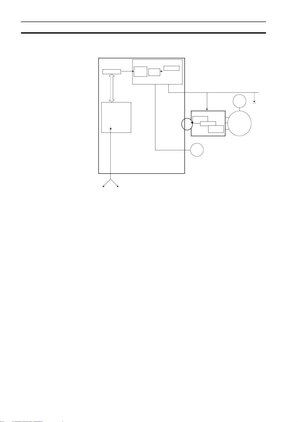
1-2 System philosophy
CJ1W-MCH72
Program Buffer
Buffer &
Buffer &
profile
profile
gererator
gererator
AXIS CONTROL LOOP
Position
Position
Loop
Loop
AXIS TYPE
AXIS TYPE
AXIS TYPE
ML
BASIC PROGRAMS
Process 1
Process 2
Process 3
…
Process 14
Comms
I/O
BUILT-IN TJ1-PLC interface
Servo Driver
Position
Position
Loop
Loop
Speed Loop
Speed Loop
ENC
Torque
Torque
Loop
Loop
ENC
MOTOR
The system philosophy is centred around the relationship between:
•System architecture
•Cycle time
• Program control and multi-tasking
• Motion sequence and axes
• Motion buffers
All othe
Servo
Drivers
A clear understanding of the relationship between these concepts is
necessary to obtain the best results for the Trajexia system.
1-2-1 Glossary
1-2-1-1 Motion sequence
The Motion Sequence is responsible for controlling the position of the axes.
1-2-1-2 Servo period
Defines the frequency at which the Motion Sequence is executed. The servo
period must be set according to the configuration of the physical axes. The
available settings are 0.5 ms, 1 ms, 2 ms or 4 ms.
1-2-1-3 Cycle time
Is the time needed to execute one complete cycle of operations in the CJ1WMCH72. The cycle time is divided in 4 time slices of equal time length, called
"CPU Tasks". The cycle time is 1ms if SERVO_PERIOD = 0.5 ms or
SERVO_PERIOD = 1 ms, 2 ms if the SERVO_PERIOD = 2 ms and 4 ms if the
SERVO_PERIOD = 4 ms
2

System philosophy Section 1-2
1-2-1-4 CPU tasks
The operations executed in each CPU task are:
CPU task Operation
First CPU task Motion Sequence
Low priority process
Second CPU task High priority process
Third CPU task Motion Sequence (only if SERVO_PERIOD = 0.5 ms)
LED Update
High priority process
Fourth CPU task External Communications
1-2-1-5 Program
A program is a piece of BASIC code.
1-2-1-6 Process
Is a program in execution with a certain priority assigned. Process 0 to 12 are
Low priority processes and Process 13 and 14 are High priority processes.
First the process priority, High or Low, and then the process number, from high
to low, will define to which CPU task the process will be assigned.
3
Motion control concepts Section 1-3
1-3 Motion control concepts
The CJ1W-MCH72 offers these types of positioning control operations:
1 Point-to-Point (PTP) control
2 Continuous Path (CP) control
3 Electronic Gearing (EG) control.
This section introduces some of the commands and parameters used in the
BASIC programming of the motion control application.
Coordinate system
Positioning operations performed by the CJ1W-MCH72 are based on an axis
coordinate system. The CJ1W-MCH72 converts the position data from either
the connected Servo Driver or the connected encoder into an internal absolute
coordinate system.
The engineering unit that specifies the distances of travelling can be freely
defined for each axis separately. The conversion is performed through the use
of the unit conversion factor, which is defined by the UNITS axis parameter.
The origin point of the coordinate system can be determined using the
DEFPOS command. This command re-defines the current position to zero or
any other value.
1-3-1 PTP control
MOVEABS(30)
MOVE(60)
MOVEABS(50)
MOVE(50)
MOVE(30)
0
50 100
A
A move is defined in either absolute or relative terms. An absolute move takes
the axis (A) to a specific predefined position with respect to the origin point. A
relative move takes the axis from the current position to a position that is
defined relative to this current position. The figure shows an example of
relative (command MOVE) and absolute (command MOVEABS) linear moves.
In point-to-point positioning, each axis is moved independently of the other
axis. The CJ1W-MCH72 supports the following operations:
• Relative move
• Absolute move
• Continuous move forward
• Continuous move reverse.
4
Motion control concepts Section 1-3
1-3-1-1 Relative and absolute moves
50
B
0
50
MOVEABS(100) AXIS(0)
MOVEABS(50) AXIS(1)
100
A
To move a single axis either the command MOVE for a relative move or the
command MOVEABS for an absolute move is used. Each axis has its own
move characteristics, which are defined by the axis parameters.
Suppose a control program is executed to move from the origin to an axis no.
0 (A) coordinate of 100 and axis no. 1 (B) coordinate of 50. If the speed
parameter is set to be the same for both axes and the acceleration and
deceleration rate are set sufficiently high, the movements for axis 0 and axis 1
will be as shown in the figure.
At start, both the axis 0 and axis 1 moves to a coordinate of 50 over the same
duration of time. At this point, axis 1 stops and axis 0 continues to move to a
coordinate of 100.
The move of a certain axis is determined by the axis parameters. Some
relevant parameters are:
/i
Parameter Description
UNITS Unit conversion factor
ACCEL Acceleration rate of an axis in units/s
DECEL Deceleration rate of an axis in units/s
2
2
SPEED Demand speed of an axis in units/s
Defining moves
B
ACCEL=10
10
0
123 456
DECEL=10
SPEED=10
MOVE(40)
A
5
Motion control concepts Section 1-3
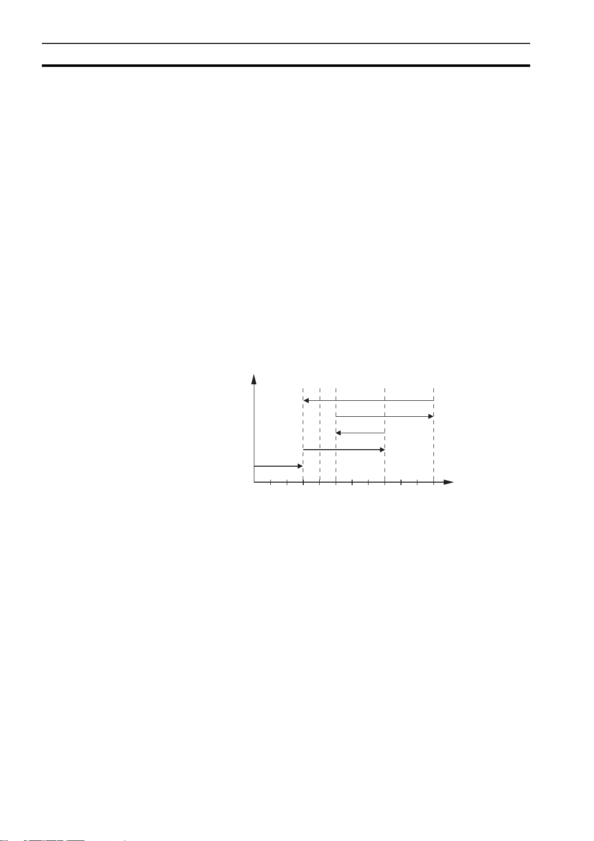
The speed profile in this figure shows a simple MOVE operation. Axis A is the
time, axis B is the speed. The UNITS parameter for this axis has been defined
for example as meters. The required maximum speed has been set to 10 m/s.
In order to reach this speed in one second and also to decelerate to zero
speed again in one second, both the acceleration as the deceleration rate
have been set to 10 m/s
travelled during the acceleration, constant speed and deceleration segments.
Suppose the distance moved by the MOVE command is 40 m, the speed
profile is given by the figure.
2
. The total distance travelled is the sum of distances
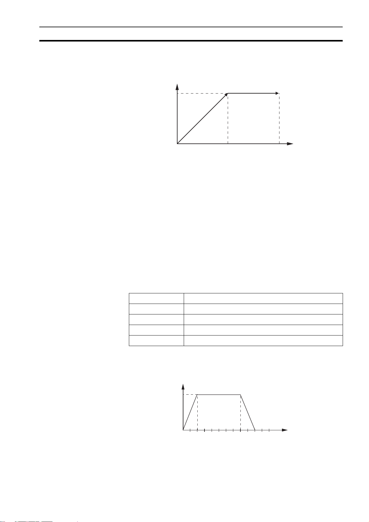
B
ACCEL=5
DECEL=10
SPEED=10
MOVE(40)
010123 456
A
The two speed profiles in these figures show the same movement with an
acceleration time respectively a deceleration time of 2 seconds. Again, Axis A
is the time, axis B is the speed.
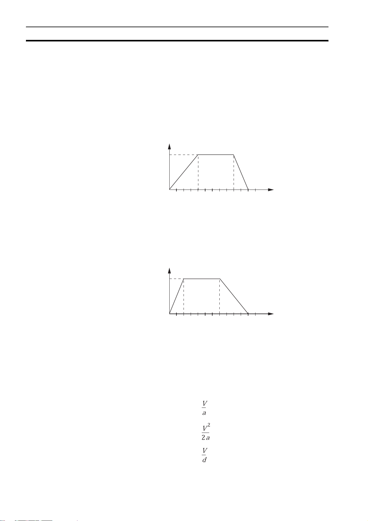
B
ACCEL=10
DECEL=5
SPEED=10
MOVE(40)
010123 456
Move calculations
The following equations are used to calculate the total time for the motion of
the axes.
• The moved distance for the MOVE command is D.
• The demand speed is V.
• The acceleration rate is a.
• The deceleration rate is d.
A
/i
Acceleration time =
Acceleration distance =
Deceleration time =
6
Motion control concepts Section 1-3
Deceleration distance =
Constant speed distance =
Total time =
1-3-1-2 Continuous moves
The FORWARD and REVERSE commands can be used to start a continuous
movement with constant speed on a certain axis. The FORWARD command
moves the axis in positive direction and the REVERSE command in negative
direction. For these commands also the axis parameters ACCEL and SPEED
apply to specify the acceleration rate and demand speed.
Both movements can be cancelled by using either the CANCEL or
RAPIDSTOP command. The CANCEL command cancels the move for one
axis and RAPIDSTOP cancels moves on all axes. The deceleration rate is set
by DECEL.
1-3-2 CP control
Continuous Path control enables to control a specified path between the start
and end position of a movement for one or multiple axes. The CJ1W-MCH72
supports the following operations:
• Linear interpolation
• Circular interpolation
•CAM control.
1-3-2-1 Linear interpolation
2
1
3
B
A
7
Motion control concepts Section 1-3
In applications it can be required for a set of motors to perform a move
operation from one position to another in a straight line. Linearly interpolated
moves can take place among several axes. The commands MOVE and
MOVEABS are also used for the linear interpolation. In this case the
commands will have multiple arguments to specify the relative or absolute
move for each axis.
Consider the three axis move in a 3-dimensional plane in the figure. It
corresponds to the MOVE(50,50,50) command. The speed profile of the
motion along the path is given in the diagram. The three parameters SPEED,
ACCEL and DECEL that determine the multi axis movement are taken from
the corresponding parameters of the base axis. The MOVE command
computes the various components of speed demand per axis.
A is the time axis, B is the speed axis.
1-3-2-2 Circular interpolation
50
1-3-2-3 CAM control
-50
It may be required that a tool travels from the starting point to the end point in
an arc of a circle. In this instance the motion of two axes is related via a
circular interpolated move using the MOVECIRC command.
Consider the diagram in the figure. It corresponds to the MOVECIRC(-100,0,-
50,0,0) command. The centre point and desired end point of the trajectory
relative to the start point and the direction of movement are specified. The
MOVECIRC command computes the radius and the angle of rotation. Like the
linearly interpolated MOVE command, the ACCEL, DECEL and SPEED
variables associated with the base axis determine the speed profile along the
circular move.
050
B
A
8
Motion control concepts Section 1-3
Additional to the standard move profiles the CJ1W-MCH72 also provides a
way to define a position profile for the axis to move. The CAM command
moves an axis according to position values stored in the CJ1W-MCH72 Table
array. The speed of travelling through the profile is determined by the axis
parameters of the axis.
The figure corresponds to the command CAM(0,99,100,20). A is the time axis,
B is the position axis.
1-3-3 EG control
Electronic Gearing control allows you to create a direct gearbox link or a linked
move between two axes. The MC Unit supports the following operations.
• Electronic gearbox
•Linked CAM
• Linked move
• Adding axes
1-3-3-1 Electronic gearbox
B
2:1
1:1
1:2
A
The CJ1W-MCH72 is able to have a gearbox link from one axis to another as if
there is a physical gearbox connecting them. This can be done using the
CONNECT command in the program. In the command the ratio and the axis to
link to are specified.
In the figure, A is the Master axis, and B is the CONNECT axis.
/i
Axes Ratio CONNECT command
0 1
1:1 CONNECT(1,0) AXIS(1)
2:1 CONNECT(2,0) AXIS(1)
1:2 CONNECT(0.5,0) AXIS(1)
9
Motion control concepts Section 1-3
1-3-3-2 Linked CAM control
B
A
Next to the standard CAM profiling tool the CJ1W-MCH72 also provides a tool
to link the CAM profile to another axis. The command to create the link is
called CAMBOX. The travelling speed through the profile is not determined by
the axis parameters of the axis but by the position of the linked axis. This is
like connecting two axes through a cam.
In the figure, A is the Master axis (0) position, and B is the CAMBOX Axis (1)
position.
1-3-3-3 Linked move
B
DC
E
A
The MOVELINK command provides a way to link a specified move to a
master axis. The move is divided into an acceleration, deceleration and
constant speed part and they are specified in master link distances. This can
be particularly useful for synchronizing two axes for a fixed period.
The labels in the figure are:
A Time axis.
B Speed axis.
C Master axis (1).
D Synchronized.
E MOVELINK axis (0).
10
Motion control concepts Section 1-3
1-3-3-4 Adding axes
B
B
B
BASE(0)
ADDAX(2)
FORWARD
MOVE(100) AXIS(2)
MOVE(-60) AXIS(2)
A
A
It is very useful to be able to add all movements of one axis to another. One
possible application is for instance changing the offset between two axes
linked by an electronic gearbox. The CJ1W-MCH72 provides this possibility by
using the ADDAX command. The movements of the linked axis will consists of
all movements of the actual axis plus the additional movements of the master
axis.
In the figure, A is the time axis and B is the speed axis.
1-3-4 Other operations
1-3-4-1 Cancelling moves
In normal operation or in case of emergency it can be necessary to cancel the
current movement from the buffers. When the CANCEL or RAPIDSTOP
commands are given, the selected axis respectively all axes will cancel their
current move.
1-3-4-2 Origin search
The encoder feedback for controlling the position of the motor is incremental.
This means that all movement must be defined with respect to an origin point.
The DATUM command is used to set up a procedure whereby the CJ1W-
MCH72 goes through a sequence and searches for the origin based on digital
inputs and/or Z-marker from the encoder signal.
A
11
Motion control concepts Section 1-3
1-3-4-3 Print registration
The CJ1W-MCH72 can capture the position of an axis in a register when an
event occurs. The event is referred to as the print registration input. On the
rising or falling edge of an input signal, which is either the Z-marker or an
input, the CJ1W-MCH72 captures the position of an axis in hardware. This
position can then be used to correct possible error between the actual position
and the desired position. The print registration is set up by using the REGIST
command.
The position is captured in hardware, and therefore there is no software
overhead and no interrupt service routines, eliminating the need to deal with
the associated timing issues.
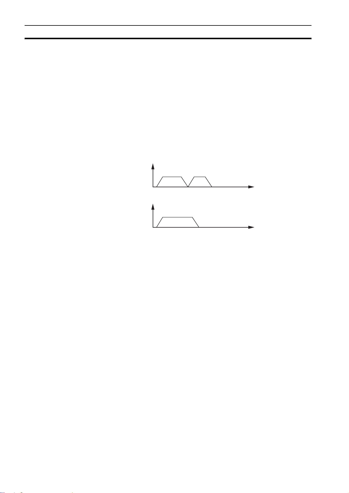
1-3-4-4 Merging moves
1-3-4-5 Jogging
B
MERGE=0
A
B
MERGE=1
A
If the MERGE axis parameter is set to 1, a movement is always followed by a
subsequent movement without stopping. The figures show the transitions of
two moves with MERGE value 0 and value 1.
In the figure, A is the time axis and B is the speed axis.
Jogging moves the axes at a constant speed forward or reverse by manual
operation of the digital inputs. Different speeds are also selectable by input.
Refer to the FWD_JOG, REV_JOG and FAST _JOG axis parameters.
12
Servo system principles Section 1-4
1-4 Servo system principles
The servo system used by and the internal operation of the CJ1W-MCH72 are
briefly described in this section.
1-4-1 Semi-closed loop system
The servo system of the CJ1W-MCH72 uses a semi-closed or inferred closed
loop system. This system detects actual machine movements by the rotation
of the motor in relation to a target value. It calculates the error between the
target value and actual movement, and reduces the error through feedback.
1-4-2 Internal operation of the CJ1W-MCH72
AB
C
2
1
D
E
3
F
G
4
I
H
J
Inferred closed loop systems occupy the mainstream in modern servo systems
applied to positioning devices for industrial applications. The figure shows the
basic principle of the servo system as used in the CJ1W-MCH72.
1 The CJ1W-MCH72 performs actual position control. The main input of the
controller is the Following Error, which is the calculated difference between
the demand position and the actual measured position.
2 The Position Controller calculates the required speed reference output
determined by the Following Error and possibly the demanded position and
the measured position. The speed reference is provided to the Servo
Driver.
3 The Servo Driver controls the rotational speed of the servo motor
corresponding to the speed reference. The rotational speed is proportional
to the speed reference.
4 The rotary encoder generates the feedback pulses for both the speed
feedback within the Servo Driver speed loop and the position feedback
within the CJ1W-MCH72 position loop.
The labels in the figure are:
A CJ1W-MCH72.
B Servo system.
C Demand position.
D Position control.
E Speed reference.
F Speed control.
G Motor.
H Encoder.
I Measured speed.
J Measured position.
13
Servo system principles Section 1-4
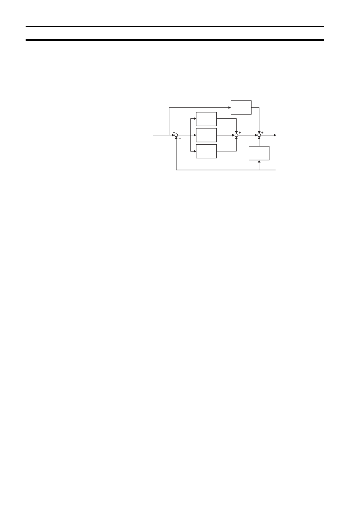
1-4-3 Motion control algorithm
The servo system controls the motor by continuously adjusting the speed
reference to the Servo Driver. The speed reference is calculated by the motion
control algorithm of the CJ1W-MCH72, which is explained in this section.
∑
K
vff
K
p
AB C
∑
K
i
∆
K
d
∆
K
ov
D
The motion control algorithm uses the demand position (A), the measured
position (D) and the Following Error (B) to determine the speed reference. The
Following Error is the difference between the demanded and measured
position. The demand position, the measured position and the Following Error
are represented by the axis parameters MPOS, DPOS and FE. Five gain
values have been implemented for the user to be able to configure the correct
control operation for each application.
C is the output signal.
• Proportional gain
The proportional gain K
Following Error E.
O
= Kp · E
p
All practical systems use proportional gain. For many just using this gain
parameter alone is sufficient. The proportional gain axis parameter is called
P_GAIN.
• Integral gain
The integral gain K
the Following Errors that have occurred during the system operation.
O
= Ki · ΣE
i
Integral gain can cause overshoot and so is usually used only on systems
working at constant speed or with slow accelerations. The integral gain axis
parameter is called I_GAIN.
• Derivative gain
The derivative gain K
change in the Following Error E and speeds up the response to changes in
error while maintaining the same relative stability.
O
= Kd · ∆E
d
Derivative gain may create a smoother response. High values may lead to
oscillation. The derivative gain axis parameter is called D_GAIN.
• Output speed gain
The output speed gain K
the change in the measured position P
O
= Kov · ∆P
ov
m
creates an output Op that is proportional to the
p
creates an output Oi that is proportional to the sum of
i
produces an output Od that is proportional to the
d
produces an output Oov that is proportional to
ov
and increases system damping.
m
14

Servo system principles Section 1-4
The output speed gain can be useful for smoothing motions but will
generate high Following Errors. The output speed gain axis parameter is
called OV_GAIN.
• Speed feed forward gain
The speed feedforward gain K
proportional to the change in demand position P
Following Error at high speed.
O
= K
vff
· ∆P
d
vff
The parameter can be set to minimise the Following Error at a constant
machine speed after other gains have been set. The speed feed forward
gain axis parameter is called VFF_GAIN.
The default settings are given in the table along with the resulting profiles.
Fractional values are allowed for gain settings.
/i
Gain Default value
Proportional gain 0.1
Integral gain 0.0
Derivative gain 0.0
Output speed gain 0.0
produces an output O
vff
and minimizes the
d
that is
vff
Speed feedforward gain 0.0
15

Trajexia system architecture Section 1-5
1-5 Trajexia system architecture
The system architecture of the Trajexia is dependant upon these
concepts:
• Program control
• Motion Sequence
• Motion buffers
• Communication
•Peripherals
These concepts depend upon the value set in the SERVO_PERIOD
parameter. The relationship between the value of SERVO_PERIOD and the
different concepts of the system architecture are describes as follows.
1-5-1 Program control
Programs make the system work in a defined way. The programs are written in
a language similar to BASIC and control the application of the axes and
modules. 14 Programs can be executed in parallel. The programs can be set
to run at system power-up, started and stopped from other programs and
executed from Trajexia Studio.
Programs execute commands to move the axes, control inputs and outputs
and make communication via BASIC commands.
1-5-2 Motion sequence
The motion sequence controls the position of all 32 axes with the actions as
follows:
• Reading the Motion buffer
• Reading the current Measured Position (MPOS)
• Calculating the next Demanded Position (DPOS)
• Executing the Position loop
• Sending the Axis reference
• Error handling
1-5-3 Motion buffers
Motion buffers are the link between the BASIC commands and the Axis control
loop. When a BASIC motion command is executed, the command is stored in
one of the buffers. During the next motion sequence, the profile generator
executes the movement according to the information in the buffer.
When the movement is finished, the motion command is removed from the
buffer.
1-5-4 Communication
The CJ1W-MCH72 can exchange data with memory areas in the PLC. This
enables the CJ1W-MCH72 to use the inputs and outputs connected to the
PLC. Also, programs in the CJ1W-MCH72 and PLC programs can exchange
control and status data.
For more information on communication and data exchange, refer to chapter
3.
1-5-5 Peripherals
16
All inputs and outputs are used with the set of parameters (IN, OP, AIN,
AOUT). The inputs and outputs are automatically detected and mapped in
Trajexia. Inverters are considered a peripheral device and have a set of
BASIC commands to control them.
Cycle time Section 1-6
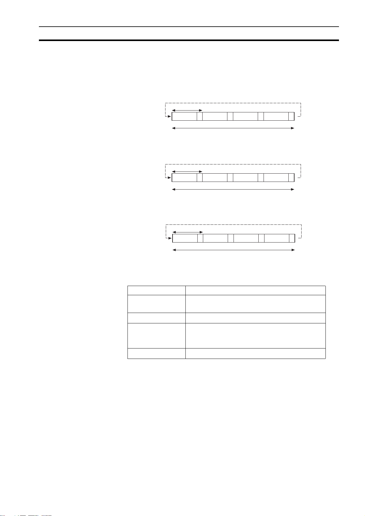
1-6 Cycle time
All processes in the Trajexia system are based on the cycle time. The cycle
time is divided into four CPU tasks:
•250 µs time intervals for a SERVO_PERIOD of 0.5 and 1.0 ms
250µs
1
2
Cycle time = 1ms
3
4
•500 µs time intervals for a SERVO_PERIOD of 2.0 ms
500 µs
1
2
Cycle time = 2 ms
3
4
• 1 ms time intervals for a SERVO_PERIOD of 4.0 ms
1 ms
1
2
Cycle time = 4 ms
3
4
The processes that can be carried out in each time interval depends on the
SERVO_PERIOD that is set.
The operations executed in each CPU task are:
CPU task Operation
First CPU task Motion Sequence
Low priority process
Second CPU task High priority process
Note The Motion sequence execution depends on setting of the SERVO_PERIOD parame-
1-6-1 Servo period
Third CPU task Motion Sequence (only if SERVO_PERIOD=0.5ms)
LED Update.
High priority process
Fourth CPU task External Communications
ter.
The SERVO_PERIOD can be set at 0.5, 1, 2 or 4 ms. The processes that take
place within the cycle time depend on the setting of the SERVO_PERIOD
parameter. The SERVO_PERIOD parameter is a Trajexia parameter that must
be set according to the system configuration.
The factory setting is 1ms (SERVO_PERIOD=1000). A change is set only
after a restart of the CJ1W-MCH72.
17
Cycle time Section 1-6
Note Only the Sigma-III Servo Driver and the Sigma-V Servo Driver support the 0.5 ms trans-
mission cycle.
1-6-1-1 Servo period 0.5 ms
The SERVO_PERIOD has a value of 0.5ms and the motion sequence is
executed every 0.5ms.
1-6-1-2 Servo period 1 ms
CPU task 1
CPU task 2
CPU task 3
CPU task 4
CPU task 1
CPU task 2
CPU task 3
Motion sequence
Low priority task (0,1,2,3...)
High priority task (13,14)
Motion sequence
LED refresh
High priority task (13,14)
Communication
Motion sequence
Low priority task (0,1,2,3...)
High priority task (13,14)
LED refresh
High priority task (13,14)
1ms
1ms
The SERVO_PERIOD has a value of 1ms and the motion sequence is
executed every 1ms. As the motion sequence is not executed during CPU task
3, there is more time for the program execution. High priority programs run
faster.
1-6-1-3 Servo period 2 ms
The SERVO_PERIOD has a value of 2ms and the motion sequence is
executed every 2.0ms.
CPU task 4
CPU task 1
CPU task 2
CPU task 3
CPU task 4
Communication
Motion sequence
Low priority task (0,1,2,3...)
High priority task (13,14)
LED refresh
High priority task (13,14)
Communication
2ms
18

Cycle time Section 1-6
1-6-1-4 Servo period 4 ms
The SERVO_PERIOD has a value of 4ms and the motion sequence is
executed every 4.0ms.
1-6-1-5 Servo period rules
The number of axes and MECHATROLINK-II slaves in the Trajexia system
determines the value of the SERVO_PERIOD system parameter.
There are 2 types of MECHATROLINK-II slaves that are supported by the
CJ1W-MCH72 units:
• Servo Drivers
• Inverters
You should comply with the most restrictive rules when you set the
SERVO_PERIOD parameter. An incorrect value of the SERVO_PERIOD
parameter results in an incorrect detection of the MECHATROLINK-II slaves.
The most restrictive rules are given in the tables below. For each unit the table
lists the maximum number of slaves the unit can control at the given
SERVO_PERIOD setting.
/i
CPU task 1
CPU task 2
CPU task 3
CPU task 4
Motion sequence
Low priority task (0,1,2,3...)
High priority task (13,14)
LED refresh
High priority task (13,14)
Communication
The CJ1W-MCH72 considers Servo Drivers as axes.
The CJ1W-MCH72 does not consider Inverters as axes.
SERVO_PERIOD Total number
of axes
Number of
MECHATROLINK-II
stations
axes inverters
4ms
Total number of
MECHATROLINK-II
stations
0.5 ms 8 4 4 4
1.0 ms 16 8 8 8
2.0 ms 16 16 8 16
4.0 ms 32 30 8 30
19

Cycle time Section 1-6
1-6-1-6 Configuration examples
Example 1
Servo Driver
Address
43
Axis 0
• 1x CJ1W-MCH72
• 3x Sigma-V Servo Driver
• 1x Encoder (Axis 0)
• SERVO_PERIOD = 0.5ms
The CJ1W-MCH72 supports 0.5ms SERVO_PERIOD with 4 axes.
If Sigma-II Servo Drivers were used in this example, the SERVO_PERIOD
would be 1.0ms, since Sigma-II servo Drivers do not support the
SERVO_PERIOD of 0.5ms.
Axis 2 Axis 3
Address44Address
45
Terminator
Axis 4
20

Cycle time Section 1-6
Example 2
Servo Driver
Axis 16
Address41Address42Address43Address44Address45Address46Address47Address
Axis 0
Address
Axis 8
Axis 1
Address4AAddress4BAddress4CAddress4DAddress4EAddress4FAddress
49
Axis 9
Axis 2
Axis 10
Axis 3
Axis 11
Axis 4
Axis 12
Axis 5
Axis 13
Axis 14
Axis 6
48
Axis 7
50
Axis 15
• 1x CJ1W-MCH72
• 16x Sigma-II Servo Driver
• 1x Encoder (Axis 16)
• SERVO_PERIOD = 4ms
The CJ1W-MCH72 supports 4ms SERVO_PERIOD with 17 axes.
Terminator
21

Program control and multi-tasking Section 1-7
1-7 Program control and multi-tasking
The Trajexia system has program, processes and multi tasking control.
1-7-1 Program control
The Trajexia system can control 14 processes that are written as BASIC
programs. When the program is set to run, the program is executed.
Processes 1 to 12 are low priority, 13 and 14 are high priority.
1-7-2 Processes
The low-priority process 0 is reserved for the Terminal window of Trajexia
Studio. This terminal window is used to write direct BASIC commands to the
CJ1W-MCH72 independent to other programs. These commands are
executed after you press the Enter button.
1-7-3 Multi-tasking
LT HT #1 HT #2
Cycle time
Each cycle time is divided into 4 time slices called CPU tasks. Processes run
in the first 3 CPU tasks according to the priority of the process.
Motion sequence and low-priority processes (A) are executed in the Low Task
(LT) period.
High priority processes (B) are executed in the high Task (HT) periods.
A
LT HT #1 HT #2
External communication that are not related to the motion network are
updated in the communications (COMS) period in the fourth CPU task.
Trajexia can control up to 14 programs at the same time.
In contrast to low priority processes, a high priority process is always available
for execution during two of the four CPU tasks. The high-priority tasks are
executed faster than the low-priority tasks, it is that they have more time
available for their execution. All the low-priority tasks must share one slot of
time and the high-priority task have their own two slots of time.
B
Cycle time
COMS.
COMS.
22

Motion sequence and axes Section 1-8
1-7-4 Multi-tasking example
1
14
10
(c/l)
1ms
1ms
141
1ms
13
1ms
14
1ms
140
1ms
13
COMS.
COMS.
(c/l)
0
(c/l)
(c/l)
3
COMS.
210
1
14
3
2
3
321
1ms
1ms
143
1ms
13
COMS.
COMS.
COMS.
2
0
(c/l)
1ms
13
14
1ms
142
1ms
32
COMS. COMS.
COMS. COMS.
COMS. COMS.
In the example 1, there are two high-priority processes, 13 and 14. The two HT
periods are reserved for these processes, one for processes 13 and one for
processes 14. The low-priority processes 3, 2, 1 and 0 are executed in the LT
period, one process per Cycle time here set to 1.0ms.
In the middle example, there is only one high-priority process, 14. Both HT
periods are reserved for this process. The low-priority processes, 3, 2, 1 and 0
are executed in the LT period, one process per cycle time.
In the lower example, there are no high-priority processes. Therefore, the HT
periods can be used for the low-priority processes. The LT period is also used
for the low-priority processes.
1-8 Motion sequence and axes
• block
•
AXIS PARAMETER
Position loop
Position loop
+
+
Profile generatorProfile generator
Demanded
Demanded
position
position
Mea s ur ed
Mea s ur ed
position
position
Motion sequence is the part of the CJ1W-MCH72 that controls the axes. The
actual way that the motion sequence operates depends on the axis type. The
axis type can be set and read by the parameter ATYPE. At start-up the
Trajexia system automatically detects the configuration of the axes.
• The default value for the parameter ATYPE for MECHATROLINK-II axes is
40 (MECHATROLINK-II position).
• The default value for the parameter ATYPE for the Encoder Interface is 44
(incremental encoder).
-
Following
Following
error
error
Speed
Speed
command
command
Servo Drive
OFF
ON
Speed loop
Torq ue
loop
M
E
23

Motion sequence and axes Section 1-8
All non allocated axes are set as a virtual axis. The value for the parameter
ATYP E is 0.
Every axis has the general structure as shown in the illustration above .
The motion sequence which will be executed at the beginning of each servo
period will contain the following elements:
1 Transfer any moves from BASIC process buffers to motion buffers (see
section 1-9).
2 Read digital inputs.
3 Load moves. (See note.)
4 Calculate speed profile. (See note.)
5 Calculate axis positions. (See note.)
6 Execute position servo. For axis 0 this also includes the Servo Driver
communications. (See note.)
7 Update outputs.
Note Each of these items will be performed for each axis in turn before moving on to the next
item.
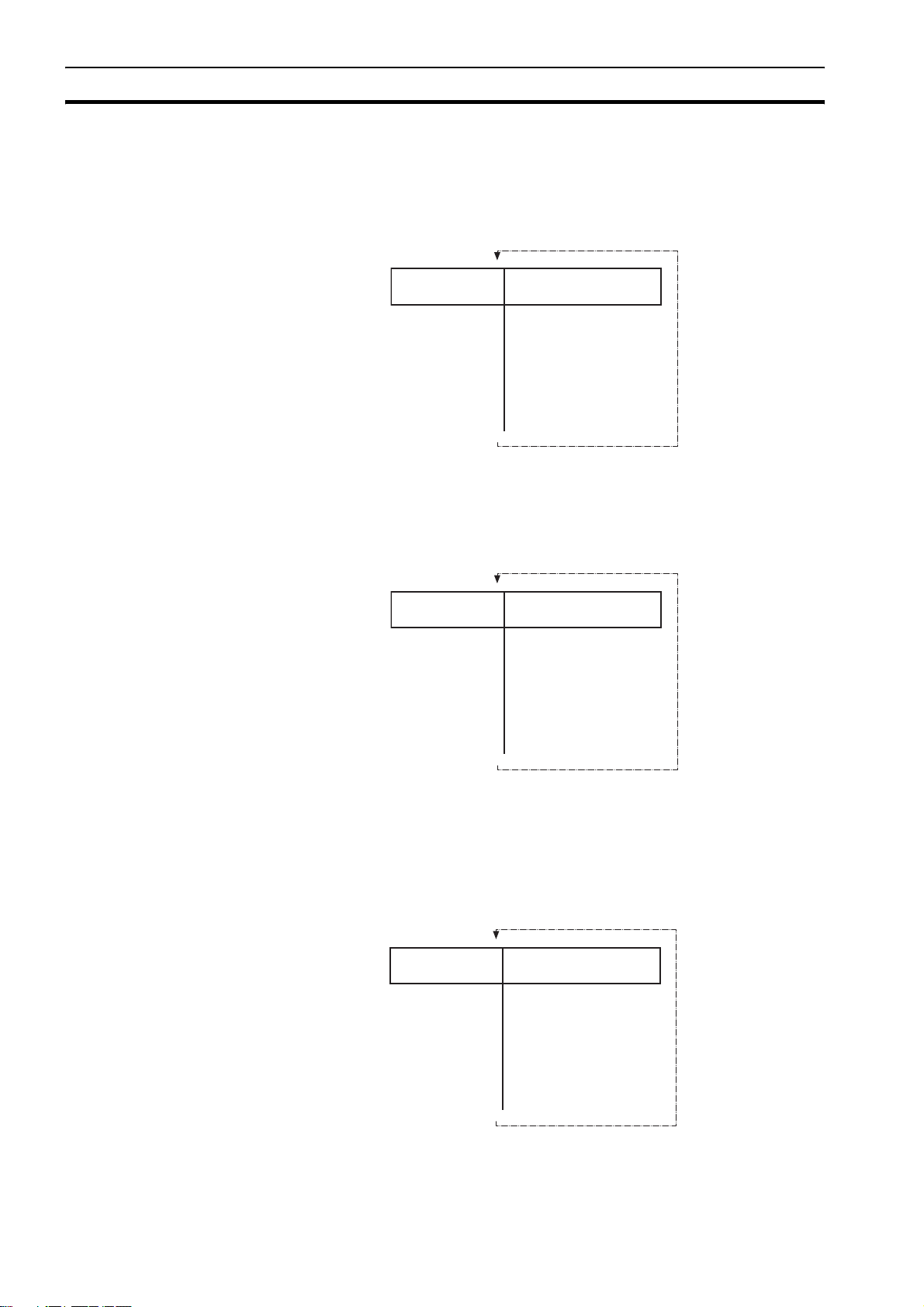
1-8-1 Profile generator
The profile generator is the algorithm that calculates the demanded position
for each axis. The calculation is made every motion sequence.
The profile is generated according to the motion instructions from the BASIC
programs.
1-8-2 Position loop
The position loop is the algorithm that makes sure that there is a minimal
deviation between the measured position (MPOS) and the demand position
(DPOS) of the same axis.
1-8-3 Axis sequence
• The motion controller applies motion commands to an axis array that is
Basic Program
.........
.........
MOVE(1000)
.........
.........
Profile generator
Demand Position
defined with the BASE command. If the motion command concerns one
axis, it is applied to the first axis in the BASE array. If the motion command
concerns more than one axis, and makes an orthogonal move, the axes
are taken from the array in the order defined by the BASE command. For
24

Motion sequence and axes Section 1-8
more information on the BASE command and the definition of the axis
sequence in an axis array, refer to the Trajexia Programming Manual,
chapter 3 (BASIC commands).
• If SERVO=OFF for one axis, the motion commands for that axis are
ignored.
• If the Following Error (FE) in one axis exceeds the parameter value
FELIMIT, the next action occurs:
- WDOG is set to OFF and all axes stop.
- SERVO for the axis that causes the error goes to OFF.
- The current move is cancelled and removed from the buffer.
1-8-4 Type of axis
/i
ATYPE Applicable to Name Description
0 All axes Virtual axis Internal axis with no physical out-
put. It is the only valid setting for
non-allocated axes. That is, those
that are not MECHATROLINK-II
Servo Drivers.
40 MECHATROLINK-II
Servo Drivers
41 MECHATROLINK-II
42 MECHATROLINK-II
43 External driver con-
nected to encoder
input
MECHATROLINK-II
Position (default)
Speed
To rq ue
Stepper output Pulse and direction outputs. Posi-
Position loop in the Servo Driver.
CJ1W-MCH72 sends position reference to the Servo Driver via
MECHATROLINK-II.
Position loop in the Trajexia.
CJ1W-MCH72 sends speed reference to the Servo Driver via
MECHATROLINK-II.
Position loop in the Trajexia.
CJ1W-MCH72 sends torque reference to the Servo Driver via
MECHATROLINK-II.
tion loop is in the driver. CJ1WMCH72 sends pulses and
receives no feed back.
44 Servo axis
(Default)
Encoder
45 Encoder
output
47 Absolute EnDat Feedback is received from an
48 Absolute
SSI
49 MECHATROLINK-II
Inverters
Inverter as
axis
CJ1W-MCH72 receives position
from an incremental encoder.
The same as stepper, but with the
phase differential outputs emulating an incremental encoder.
EnDat absolute encoder.
Feedback is received from an SSI
absolute encoder.
Inverters (with built-in encoder
interface) are controlled on the
MECHATROLINK-II bus as servo
axes.
25

Motion sequence and axes Section 1-8
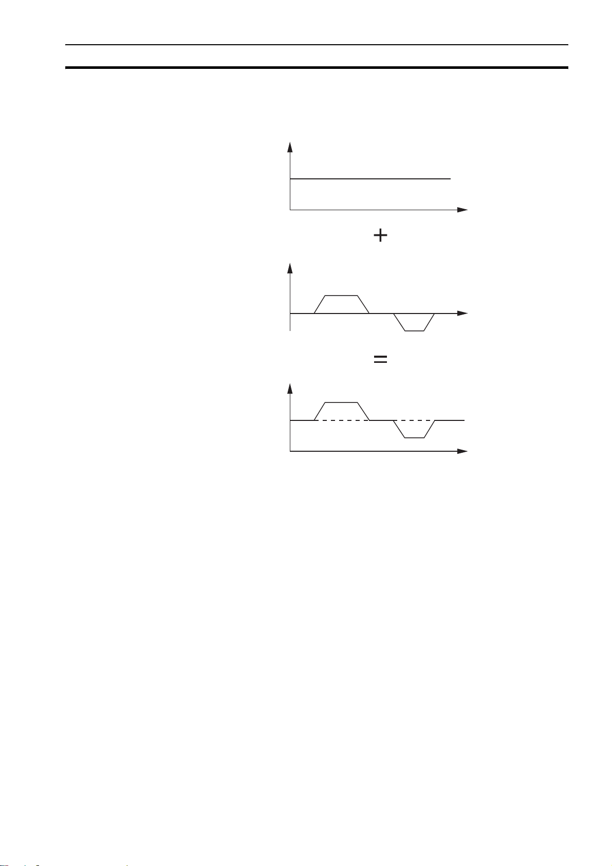
1-8-4-1 Virtual axis ATYPE=0
Profile generator
MEASURED
You can split a complex profile into two or more simple movements, each
assigned to a virtual axis. These movements can be added together with the
BASIC command ADDAX then assigned to a real axis.
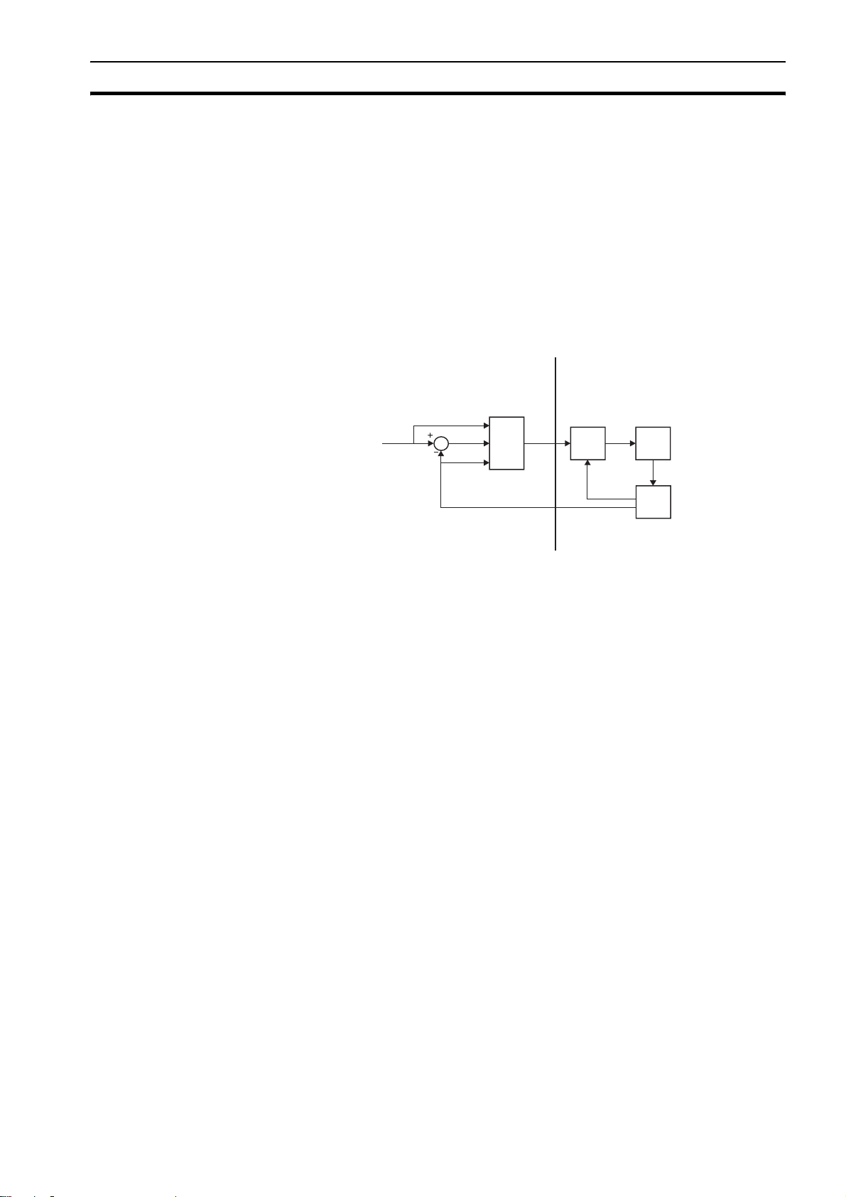
1-8-4-2 MECHATROLINK-II position ATYPE=40
CJ1W-MCH72
SERVO = OFF SERVO = OFF
Profile generator
Demanded
position
Measured
position
Position loop
+
_
Following
error
Position Loop is
deactivated
(Gains are not
used!)
POSITION
Speed
command
=
DEMAND
POSITION
ML-II
Position
command
SERVO
Position Loop
Speed Loop
Torque Loop
M
E
With SERVO = ON, the position loop is closed in the Servo Driver. Gain
settings in the CJ1W-MCH72 have no effect. The position reference is sent to
the Servo Driver.
Note Although MPOS and FE are updated, the real value is the value in the Servo Driver.
The real Following Error can be monitored by the DRIVE_MONITOR parameter by setting DRIVE_CONTROL = 2.
Note The MECHATROLINK-II position ATYPE = 40 is the recommended setting to obtain a
higher performance of the servo motor.
26

Motion sequence and axes Section 1-8
1-8-4-3 MECHATROLINK-II speed ATYPE=41
CJ1W-MCH72
Demanded
position
Measured
position
Position loop
+
_
Following
SERVO = OFF SERVO = OFF
Profile generator
With SERVO = ON, the position loop is closed in the CJ1W-MCH72.
Speed reference is sent to the Servo Driver. For Mechatrolink Servo Drivers,
this axis type is not recommended, since there is one cycle delay in the loop
(DPOS(n) is compared with MPOS(n-1)).
With SERVO = OFF, the speed reference is sent via S_REF command.
0x40000000 means maximum speed of the servo motor. This is the
recommended setting.
1-8-4-4 MECHATROLINK-II torque ATYPE=42
error
Speed
command
ML-II
Speed
command
SERVO
Speed Loop
Torque Loop
E
M
SERVO
Torque Loop
E
M
Profile generator
CJ1W-MCH72
Demanded
position
Measured
position
Position loop
+
_
Following
error
Torque
command
SERVO = OFF SERVO = OFF
ML-II
Torque
command
With SERVO = ON, only the torque loop is closed in the Servo Driver. The
torque reference in the Servo Driver depends on the FE and the gain.
With SERVO = OFF, the torque reference is sent directly via the T_REF
command. 0x40000000 is the maximum torque of the servo motor.
Note To monitor the torque in the servo in DRIVE_MONITOR, set DRIVE_CONTROL=11.
27

Motion sequence and axes Section 1-8
1-8-4-5 Stepper output ATYPE=43
The position profile is generated and the output from the system is a pulse
train and direction signal. This is useful to control a motor via pulses or as a
position reference for another motion controller.
1-8-4-6 Servo axis ATYPE=44
CJ1W-MCH72
Measured
Position
With SERVO = OFF, the position of the external incremental encoder is read.
1-8-4-7 Encoder output ATYPE=45
Profile generator
AXIS 1
ATYPE = 45
Demanded
position
The position profile is generated and the output from the system is an
incremental encoder pulse. This is useful to control a motor via pulses or as a
position reference for another motion controller.
1-8-4-8 Absolute EnDat encoder ATYPE=47
With SERVO = OFF, the position of the external absolute EnDat encoder is
read.
1-8-4-9 Absolute SSI encoder ATYPE=48
With SERVO = OFF, the position of the external absolute SSI encoder is read.
CJ1W-MCH72
28

Motion sequence and axes Section 1-8
1-8-4-10 Inverter axis ATYPE=49
INVERTER
Speed Loop
E
M
Profile generator
SERVO = OFF
Demanded
position
Measured
position
CJ1W-MCH72
Position loop
+
_
Following
error
Speed
command
SERVO = OFF
ML-II
Speed
command
DPRAM
REFRESH
EVERY 5ms
This type allows Inverters (with built-in encoder interface) to be controlled on
the MECHATROLINK-II bus as servo axes.
From the controller point of view, Inverter axes are handled the same as servo
axes in MECHATROLINK-II Speed Mode (ATYPE=44).
Unlike the other axis types, this Inverter axis must be defined
programmatically with function 8 of the command INVERTER_COMMAND.
The Speed command to the Inverter and the feedback from the encoder is
refreshed in the Inverter with a few milliseconds delay. This is an inverter
limitation. This means that the use of the Inverter is similar to the use of a
Servo Driver, but the performance is lower.
1-8-4-11 Summary of axis types and control modes
The following table lists the axis types and their recommended modes for
speed control, position control and torque control.
/i
ATYPE SERVO Mode Comment
40 OFF Position
(MECHATROLINK-II)
40 ON Position
(MECHATROLINK-II)
41 OFF Speed
(MECHATROLINK-II)
41 ON Position
(MECHATROLINK-II)
42 OFF Torque
(MECHATROLINK-II)
42 ON Position via torque
(MECHATROLINK-II)
The position loop is closed in the Servo
Driver. No new motion command is
allowed.
Recommended mode for position control
with MECHATROLINK-II axes.
Recommended mode for speed control
with MECHATROLINK-II axes. Set the
speed with S_REF.
The position loop is closed in Trajexia.
This gives lower performance than closing
the position loop in the Servo Driver.
Recommended mode for torque control
with MECHATROLINK-II axes. Set the
torque with T_REF.
The position loop is closed in Trajexia.
The output of the position loop is sent as
the torque reference to the Servo Driver.
29

Motion sequence and axes Section 1-8
ATYPE SERVO Mode Comment
49 OFF Speed Inverter (with built-in encoder interface)
controlled on the MECHATROLINK-II bus
as a servo axis. Set the speed with
S_REF.
49 ON Position Inverter (with built-in encoder interface)
controlled on the MECHATROLINK-II bus
as a servo axis. The position loop is
closed in Trajexia.
30

Motion buffers Section 1-9
1-9 Motion buffers
AXIS BUFFER
BASIC PROGRAM
BASIC PROGRAM
..... ..
..... ..
MOVE(-500)
MOVE(-500)
..... ..
..... ..
MOVE(1000)
MOVE(1000)
..... ..
..... ..
CONNECT(1,1)
CONNECT(1,1)
..... ..
CONNECT(1,1) AXIS(2)
PROCESS BUFFER
The motion buffer is a temporary store of the motion instruction from the
BASIC program to the profile generator.
The BASIC program continues while the instruction waits in the buffer.
There are three types of buffer:
• MTYPE. The current movement that is being executed. MTYPE relates to
the axis and not to the process.
• NTYPE. The new movement that waits for execution. NTYPE relates to the
axis and not to the process.
• Process Buffer. The third buffered movement cannot be monitored. The
process buffer relates to the process and not to the axis.
(one per axis )
NTYPE
MTYPE
Profile generator
Waiting to be executed
MOTION COMMAND
Currently executed
MOTION COMMAND
DEMAND
POSITION
It is possible to check if the process buffer is full by checking the PMOVE
process parameter.
Process 1
Process 2
Process 3
Process 4
Process 5
Process 6
Process 7
Process 14
Process Buffer
Process Buffer
Process Buffer
Process Buffer
Process Buffer
Process Buffer
Process Buffer
Program Buffer
Each process has its own
“Process Buffer”
Axis 0
Axis 1
Axis 2
Axis 3
Axis 15
Each Axis has its own
2 buffers: NTYPE & MTYPE
WAITING EXEC UTING
NTYPE
NTYPE
NTYPE
NTYPE MTYPE
NTYPE MTYPE
MTYPE
MTYPE
MTYPE
When a motion instruction is executed in the BASIC program, the instruction is
loaded into the process buffer and distributed to the corresponding axis buffer
in the next motion sequence.
If a fourth motion instruction is executed and the three buffers are full, the
BASIC program stops execution until a process buffer is free for use.
31

Motion buffers Section 1-9
EXAMPLE:
BASIC PROGRAM
.......
MOVE(-500)
.......
MOVE(1000)
.......
DATUM (3)
.......
MOVE(200)
.......
BASIC PROGRAM
.......
MOV E(- 50 0)
.......
MOVE(1000)
.......
DATUM( 3)
.......
MOVE(200)
.......
BASIC PROGRAM
.......
MOVE (-500 )
.......
MOVE(1000)
.......
DATUM (3)
.......
MOVE(200)
.......
BASIC PROGRAM
BASIC PROGRAM
.......
.......
MOVE (-500 )
MOVE (-500 )
.......
.......
MOVE(1000)
MOVE(1000)
.......
.......
DATUM (3)
DATUM (3)
.......
.......
MOVE(200)
MOVE(200)
.......
.......
BASIC PROGRAM
BASIC PROGRAM
.......
.......
MOVE(-500)
MOVE(-500)
.......
.......
MOVE(1000)
MOVE(1000)
.......
.......
DATU M(3)
DATU M(3)
.......
.......
MOVE(200)
MOVE(200)
.......
.......
BASIC PROGRAM
BASIC PROGRAM
.......
.......
MOV E(-50 0)
MOV E(-50 0)
.......
.......
MOVE(1000)
MOVE(1000)
.......
.......
DATUM (3)
DATUM (3)
.......
.......
MOVE(200)
MOVE(200)
.......
.......
BUFFER
--------------------------------NTYPE IDLE
--------------------------------MTYPE MOVE(-500)
- - - -
BUFFER
- - - -
--------------------------------NTYPE MOVE(1000)
--------------------------------MTY PE MOV E( -50 0)
BUFFER
DATUM(3)
------------------------------- -NTYPE MOVE(1000)
------------------------------- -MTYPE MOVE(-500)
BUFFER
BUFFER
MOVE(200)
MOVE(200)
------------------------------- --
------------------------------- -NTYPE DATUM(3)
NTYPE DATUM(3)
------------------------------- --
------------------------------- -MTYPE MOVE(1000)
MTYPE MOVE(1000)
BUFFER
BUFFER
- - - - - -
- - - - - -
---------------------------------
--------------------------------NTYPE MOVE(200)
NTYPE MOVE(200)
---------------------------------
--------------------------------MTYPE DATUM(3)
MTYPE DATUM(3)
BUFFER
BUFFER
- - - - - -
- - - - - -
---------------------------------
--------------------------------NTYPE IDLE
NTYPE IDLE
---------------------------------
--------------------------------MTYPE MOVE(200)
MTYPE MOVE(200)
MOVE -500
MOVE -500
MOVE -500
MOVE -500
MOVE -500
MOVE -500
MOVE -500
MOVE -500
MOV E -50 0
MOVE 1000
MOVE 1000
MOVE 1000
MOVE 1000
MOVE 1000
MOVE 1000
DATUM (3)
DATUM (3)
DATU M (3)
DATU M (3)
MOVE 200
MOVE 200
1.- All buffers are empty
and a movement is
loaded. The movement
starts to execute.
2.- A second movement is
loaded while the first one
is not finished.
The new movemen t waits in the
second buffer.
3.- A third movement can
still be stored in the process buffer.
If the basic
‘MOVE(200)’ it will w ait.
4.- The first movement has
finished. Thebuffer moves
by one position .
The next movement starts to
execute.
5.- As the sent
movements are finished,
the buffer
6.- If no new movements
are executed, finally, the
buffer will become empty
and the profile generator
becomes inactive.
program reaches
empties.
Example of buffered instructions:
32

Mechanical system Section 1-10
1-10 Mechanical system
1-10-1 Inertia ratio
The inertia ratio is a stability criterion. The higher the intertia of the load in
relation to the intertia of the motor, the lower the gains you can set in your
system before you reach oscillation, and the lower the performance you can
reach.
With a ratio of 1:30 for small Servo Drivers and a ratio of 1:5 for big Servo
Drivers you can reach the maximum dynamic of the motor-driver combination.
1-10-2 Rigidity
If a machine is more rigid and less elastic, you can set higher gains without
vibration, and you can reach higher dynamic and lower Following Error.
1-10-3 Resonant frequency
A mechanical system has at least one resonant frequency. If you excite your
mechanical system to the resonant frequency, it starts oscillating. For motion
systems, it is best to have mechanical systems with a very high resonant
frequency, that is, with low inertia and high rigidity.
The resonant frequency of the mechanical system is the limit for the gain
settings.
33

Axis numbers Section 1-11
1-11 Axis numbers
The CJ1W-MCH72 has a maximum of 31 non-virtual axes:
• 30 MECHATROLINK-II axes
• 1 Flexible axis (on the Encoder Interface)
MECHATROLINK-II slaves can have a station address that ranges from 41
hex to 5F hex. These station addresses correspond to axis numbers 0 to 29.
The first non-assigned axis number, that is, the first axis number that is not
assigned to a MECHATROLINK-II station address, is used for the flexible axis
on the CJ1W-MCH72 encoder interface.
34

Unit components Section 2-1
SECTION 2
Installation and wiring
2-1 Unit components
The CJ1W-MCH72 Motion Control Unit has the following components:
MCH72
F
OPEN
RUN
ERC
ERH
WDOG
BATTERY
BF
E
I/O
CJ1W-MCH72 Motion Control Unit
/i
Label Description
MLK
Enc.
0
1
2
3
4
5
6
7
UNIT
No.
A
B
C
D
A Status LED indicators
B Unit number selector switch
C MECHATROLINK-II connector
D Encoder connector
E I/O connector
F Battery compartment
2-1-1 Status LED indicators
The CJ1W-MCH72 has 5 status LEDs. They indicate the operational mode
and the status of the CJ1W-MCH72. The status LEDs are given in the table
below.
35

Unit components Section 2-1
RUN
ERC
ERH
WDOG
BF
Status LEDs
/i
LED Color Status Description
RUN Green OFF • Startup test failed, unit not operational
• Fatal error, operation stopped
Flashing Detection of MECHATROLINK-II slaves and assignment
of axes in progress
ON Unit is ready to execute BASIC commands
ERC Red OFF Unit is in normal operation
Flashing
Hardware error
during
startup
Flashing
Low battery
during
execution
ON Error log access error
ERH Red OFF CPU in normal operation
ON Communication error with PLC CPU
WDOG Green OFF Unit does not operate a Servo Driver
ON Unit operates a Servo Driver
BF Red OFF Normal operation
ON MECHATROLINK-II bus fault
Also, the CJ1W-MCH72 has 8 general-purpose LEDs. The function of the
general-purpose LEDs can be controlled with the DISPLAY system parameter.
The table below lists the configuration for the LEDs and the DISPLAY=n
command where n ranges from 0 to 7.
/i
LED n=0 n=1 n=2 n=3 n=4 n=5 n=6 n=7
0 IN0 IN8 IN16 IN24 OUT0 OUT8 OUT16 OUT24
1 IN1 IN9 IN17 IN25 OUT1 OUT9 OUT17 OUT25
36
2 IN2 IN10 IN18 IN26 OUT2 OUT10 OUT18 OUT26
3 IN3 IN11 IN19 IN27 OUT3 OUT11 OUT19 OUT27
4 IN4 IN12 IN20 IN28 OUT4 OUT12 OUT20 OUT28
5 IN5 IN13 IN21 IN29 OUT5 OUT13 OUT21 OUT29
6 IN6 IN14 IN22 IN30 OUT6 OUT14 OUT22 OUT30
7 IN7 IN15 IN23 IN31 OUT7 OUT15 OUT23 OUT31

Unit components Section 2-1
T
For example: if the command DISPLAY=1 is executed, LED 5 reflects the
activity of input IN13 (pin 16) of the 28-pin I/O connector.
2-1-2 Unit number selector switch
The unit number identifies each individual CPU bus unit when more than one
CPU bus unit is connected to the same PLC. The unit number must be unique
for each CPU bus unit. If the unit number is not unique, the PLC system
cannot start correctly.
UNI
No.
Unit number selector switch
The unit number can range from 0 hex to F hex.
2-1-2-1 Word allocations for CPU bus units
Words are automatically allocated in the CIO area of CJ-series PLC systems.
The CJ1W-MCH72 uses these words to receive control data from the CPU
and to notify the CPU of its status and the status of the communication.
The word addresses in the allocated areas depend on the unit number.
Because the word addresses are hard-coded in user programs, a user
program becomes invalid when the unit number is changed.
The table below gives the relation between the unit number and the allocated
CIO area words.
/i
Unit number Allocated words Unit number Allocated words
2-1-3 Battery
0 hex (0) CIO1500..CIO1524 8 hex (8) CIO1700..CIO1724
1 hex (1) CIO1525..CIO1549 9 hex (9) CIO1725..CIO1749
2 hex (2) CIO1550..CIO1574 A hex (10) CIO1750..CIO1774
3 hex (3) CIO1575..CIO1599 B hex (11) CIO1775..CIO1799
4 hex (4) CIO1600..CIO1624 C hex (12) CIO1800..CIO1824
5 hex (5) CIO1625..CIO1649 D hex (13) CIO1825..CIO1849
6 hex (6) CIO1650..CIO1674 E hex (14) CIO1850..CIO1874
7 hex (7) CIO1675..CIO1699 F hex (15) CIO1875..CIO1899
The battery makes sure that the following RAM data is preserved when the
power supply is off:
• User programs
•VR variables
• Table memory
If the battery is not installed, or the battery voltage is too low, the RAM data is
lost when the power supply is off.
User programs, VR variables and TABLE memory can be stored into flash
memory, which do not need battery back up, on user request using the BASIC
commands EPROM and FLASHVR.
37

Unit components Section 2-1
2-1-3-1 Battery lifetime
The maximum lifetime of a battery is 5 years when the ambient temperature is
25°C. The lifetime of the battery is shorter when the ambient temperature is
higher. The lifetime of the battery is also shorter when there is no power supply
to the unit for long periods.
2-1-3-2 Low-battery indicator
If a low-battery error occurs, the ERC LED flashes, the BATTERY_LOW
parameter is ON, and bit 3 of status word n+2 is set (see section 3-3-1-2). If
this occurs, perform the following steps:
1 Check if the battery is installed correctly.
2 If the battery is installed correctly, replace it.
When a low-battery error occurs, the battery can continue to function for 5
days if the ambient temperature is 25°C and if power is supplied to the PLC
system at least one time per day. If the power is not turned off until the battery
is replaced, the battery failure and the resulting loss of RAM data can be
delayed.
If the ambient temperature is more than 25°C, the battery can only continue for
less than 5 days. If the ambient temperature is 40°C, the battery can continue
for 4 days. If the ambient temperature is 55°C, the battery can continue for 2
days.
2-1-3-3 Replacing the battery
When replacing the battery, make sure that the following is adhered to:
• Use the CJ1W-BAT01 as a replacement battery.
• Do not use a replacement battery that is older than 2 years. The production
date of the battery is shown on the label, in the format yy-mm, where yy is
the year and mm is the month.
• Make sure that the sensitive internal components of the CJ1W-MCH72
cannot be damaged by static electricity when the battery is replaced. This
can be done in two ways:
1 Turn the power off. (This is the recommended way.)
2 Leave the power on, and touch a grounded piece of metal to discharge
• Make sure that an experienced technician is in charge when the battery is
replaced. This is required by UL standards.
To replace the battery, perform the following steps:
1 Make sure that the power to the unit is on for at least 5 minutes.
2 Turn the power to the unit off.
CJ1W-BAT01
08-03
Production date of the battery: March 2008.
static electricity before replacing the battery.
38
Note You must perform the following steps within 5 minutes. If you do not perform the steps
within 5 minutes, the RAM can be deleted.
3 Open the battery compartment.
4 Remove the old battery (A) from the battery compartment.

Unit components Section 2-1
B
A
Battery (A) and battery connector (B)
5 Remove the battery connector (B) of the old battery.
6 Connect the battery connector (B) of the new battery.
7 Install the new battery (A) in the battery compartment.
8 Close the battery compartment.
When the new battery is installed, the low-battery error is cleared.
!WARNING These actions can cause the battery to leak, burn or rupture, which can lead to fire,
injury, loss of property and death.
• Do not short-circuit the battery terminals.
• Do not charge the battery.
• Do not disassemble the battery.
• Do not heat the battery or set fire to the battery.
!WARNING Do not use a battery that is dropped on the floor or that is subjected to a shock. The
battery can leak.
2-1-4 I/O connector
The I/O connector is a 28-pin connector used to wire to an external I/O. All I/
Os are general-purpose I/Os. Functions like limit inputs and origin proximity
inputs can be allocated.
The recommended connector is the Weidmuller B2L 3.5/28 LH connector.
2-1-5 MECHATROLINK-II connector
The MECHATROLINK-II connector is used to connect the CJ1W-MCH72 unit
to a MECHATROLINK-II network.
2-1-6 Encoder connector
The encoder connector of the MCH72 supports different types of encoders. It
can also act as a reference output. It supports the following:
• Incremental encoder input, for line-driver type encoders
• Two different absolute encoder standards: SSI and EnDat
• Incremental encoder output, to simulate a line-driver type encoder
• Stepper output, to control stepper drivers
39

Wiring Section 2-2
2-2 Wiring
2-2-1 I/O connector
The I/O connector is a 28-pin connector. Input 0 and input 1 can also be used
as registration inputs.
1
3
5
7
9
11
13
15
17
19
21
23
25
27
I/O connector pins
2
4
6
8
10
12
14
16
18
20
22
24
26
28
40
The connections of the pins are given in the table below.
/i
Pin Connection Pin Connection
1 Input common 2 Input common
3 Registration input 0 4 Registration input 1
5 Input 2 6 Input 3
7 Input 4 8 Input 5
9 Input 6 10 Input 7
11 Input 8 12 Input 9
13 Input 10 14 Input 11
15 Input 12 16 Input 13
17 Input 14 18 Input 15
19 Output 8 (PSWITCH) 20 Output 9
21 Output 10 22 Output 11
23 Output 12 24 Output 13
25 Output 14 26 Output 15

Wiring Section 2-2
Pin Connection Pin Connection
27 0 V Output common 28 24 V Power supply input for the outputs
2-2-1-1 Specifications
The table below shows the digital input specifications of input 0 to input 3 for
the I/O.
/i
Item Specification
Typ e NP N/PN P
Maximum voltage 24 VDC +10%
See footnote
Input current 8 mA at 24 VDC
ON voltage 17 VDC min.
OFF voltage 5 VDC max.
Maximum response time 1250 µs if the servo period equals 0.5 ms or 1.0 ms
2500 µs if the servo period equals 2.0 ms
1
Registration response time
1 µs typical
(Inputs 0 and 1)
Ambient operating temperature 0°C to 55°C
When all digital inputs are on: max. 45°C
When max. 8 digital inputs are on: max. 55°C
1. For UL certified applications always use, for external power supply, a
Class 2 power supply.
CJ1W-MCH72
3
I0
External power
supply 24V
COM
1
Common for Input circuits
Circuit configuration for input 0 to input 3
The table below shows the digital input specifications of input 4 to input 15 for
the I/O.
/i
Item Specification
Typ e NP N/PN P
Maximum voltage 24 VDC +10%
See footnote
1
Input current 3.2 mA at 24 VDC
ON voltage 12 VDC min.
OFF voltage 5 VDC max.
Maximum response time 1250 µs if the servo period equals 0.5 ms or 1.0 ms
2500 µs if the servo period equals 2.0 ms
41

Wiring Section 2-2
Item Specification
Ambient operating temperature 0°C to 55°C
When all digital inputs are on: max. 45°C
When max. 8 digital inputs are on: max. 55°C
1. For UL certified applications always use, for external power supply, a
Class 2 power supply.
CJ1W-MCH72
I4
7
External power
supply 24V
1
COM
Common for Input circuits
Circuit configuration for input 4 to input 15
The table below shows the digital output specifications of output 8 to output 15
for the I/O.
/i
Item Specification
Typ e PN P
Maximum voltage 24 VDC +10%
See footnote
1
Current capacity 100 mA for each output
800 mA in total for the group of 8 outputs
Protection Over current
Over temperature
2 A fuse on common
Maximum response time 250 µs for ON, 350 µs for OFF, if the servo period equals
0.5 ms or 1.0 ms
500 µs for ON, 600 µs for OFF, if the servo period equals
2.0 ms
150 µs when the HW_PSWITCH is used
1. For UL certified applications always use, for external power supply, a
Class 2 power supply.
CJ1W-MCH72
Equivalent
circuit
isolated from the system)
Internal circuits (galvanically
To other output circuits
2A Fuse
24V output supply
28
19 O8
27
0Voutput
External
power
supply
24V
Load
42
Circuit configuration for output 4 to output 15

Wiring Section 2-2
2-2-2 Encoder connector
The connections of the pins are given in the table below.
9
8
7
6
4
3
2
1
Encoder connector pins
/i
5
Pin Incremental
encoder input
1NC
2 A+ A+ Step+ Clock+
3 A- A- Step- Clock-
4B+ B+ Dir+
5B- B- Dir-
6 5 V Encoder power supply
7 Z+ Enable+ Enable+ Data+
Incremental
1
encoder output
Stepper output SSI, EnDat
2-2-2-1 Specifications
8 Z- Enable- Enable- Data-
9 0 V Encoder ground
Shell FG
1. With the VERIFY parameter the input type can be changed from phase
differential (VERIFY=ON, default) to Step (Channel A) and Direction
(Channel B) (VERIFY=OFF).
The table below shows the specifications.
/i
Item Specification
Signal level EIA RS-422A Standards
Input impedance 48 kΩ min.
Current capacity 20 mA
Termination None
Maximum response time registration 0.5 µs
43

Wiring Section 2-2
2-2-3 Incremental encoder
An incremental encoder has the following phase definition:
• An advanced phase A for forward rotation.
• An advanced phase B for reverse rotation.
By monitoring the relative phase of the 2 signals, you can easily detect the
rotation direction. If signal A leads signal B, the movement is clockwise and
the counter increments. If channel B leads channel A, the movement is
counterclockwise and the counter decrements.
Most rotary encodes also provide an additional Z marker. This Z marker is a
reference pulse within each revolution. With these 3 signals, you can
determine the direction, the speed and the relative position.
A+ /
STEP+ /
...
A- /
STEP- /
...
B+ /
DIR+ /
...
B- /
DIR- /
...
Z+ /
ENA+ /
...
Z- /
ENA- /
...
+5V
2
3
4
5
7
8
6
9
0V
CJ1W-MCH72
+5V
0V
Circuit configuration for the encoder interface
2-2-3-1 Encoder input
The pulse ratio of the CJ1W-MCH72 is 1: every encoder edge (i.e., a pulse
edge for either phase A or B) is equal to one internal count.
D
E
A
B
7766554433221100
C
Encoder edges
The figure shows phase A (A), phase B (B) and the number of counts (C) for
forward or clockwise rotation (D) and reverse or counterclockwise rotation (E).
The signals A, B and Z appear physically as A+ and A-, B+ and B- and Z+ and
Z-. They appear as differential signals on twisted-pair wire inputs. This makes
sure that common mode noise is rejected. When you use an encoder from
other manufacturers, check the encoder specification for the phase
44

Wiring Section 2-2
advancement carefully. If the phase definition is different from the phase
definition of the standard OMRON equipment, reverse the B-phase wiring
between the CJ1W-MCH72 and the encoder.
Note The encoder interface of the CJ1W-MCH72 does not have termination inside. In case
of long distances or disturbed communication, add external termination to the interface.
2-2-3-2 Registration
When using the incremental encoder interface of the CJ1W-MCH72, the
CJ1W-MCH72 can capture the position of the Flexible Axis in a register when
an event occurs. The event is called the print registration input. On the rising
or falling edge of an input signal (either the Z marker or one of the first 2 digital
inputs), the CJ1W-MCH72 captures the position of the axis in the hardware.
You can use this position to correct possible errors between the actual position
and the desired position.
To set up the print registration, you can use the REGIST command. The
position is captured in the hardware, which means that there is no software
overhead. Therefore, you do not have to deal with timing issues.
For more information on how to use the registration inputs, refer to the
REGIST command in section 4-2-197.
2-2-3-3 Hardware PSWITCH
The MCH72 has one output (output 8) that can be used as a hardware
position switch. This output goes on when the measured position of the
Flexible Axis is reached. It goes off when another measured position is
reached.
The output is driven by hardware only. This means that the response times do
not have software delays. For more information on using the position switch,
refer to section 4-2-128 on the HW_PSWITCH command.
2-2-3-4 Connection example
The table below and the figure give an example of the OMRON E6B2-CWZ1Z
encoder connected to the CJ1W-MCH72.
/i
A+ Black 2 A+
A- Black/red 3 A-
B+ White 4 B+
B- White/red 5 B-
CJ1W-MCH72
A+
AB+
BZ+
Z0 V (COM)
5 VDC
Encoder input connection
E6B2-CWZ1Z encoder CJ1W-MCH72 encoder interface
Signal Wire color Pin Signal
2
3
4
5
7
8
9
6
45

Wiring Section 2-2
E6B2-CWZ1Z encoder CJ1W-MCH72 encoder interface
Signal Wire color Pin Signal
Z+ Orange 7 Z+
Z- Orange/red 8 Z-
0 V (COM) Blue 9 0 V Encoder ground
5 VDC Brown 6 5 V
2-2-3-5 Encoder output
A
B
C
The CJ1W-MCH72 can generate encoder-type pulses. For each internal count
(C), the CJ1W-MCH72 produces one encoder edge for phase A (A) or phase
B (B).
2-2-4 Absolute encoder
2-2-4-1 SSI
SSI (Synchronous Serial Interface) is a digital system for transferring data in
serial form. SSI is the most widely used serial interface between absolute
sensors and controllers. SSI uses a pulse train from the controller to clock out
the data from the sensor. The SSI interface of the CJ1W-MCH72 accepts
absolute values from an encoder if the data is in Gray Code format or in binary
format and if the resolution is 25 bits or less. The number of bits, and therefore
the number of clock pulses sent to the encoder in each frame, is
programmable. You set this number with the BASIC command
ENCODER_BITS = n.
When you have initialized the CJ1W-MCH72 with the ENCODER_BITS
command, the CJ1W-MCH72 continuously sends clock pulses to the encoder.
These clock pulses are sent in frames of n+2 pulses, where n is the bit count
set. The clock rate is fixed at 200 kHz. The clock interval between frames is 32
µs. The resulting maximum cable length between the controller and the sensor
is 200 m.
01234567
Encoder edges
46

Wiring Section 2-2
C
A
D
EF
B
µs32
GG
SSI pulses
The labels in the figure are:
A Timing diagram
B Clock sequence
CClock
DData
E MSB (Most Significant Bit)
F LSB (Least Significant Bit)
GClock frame
When the data is clocked into the CJ1W-MCH72, the position value is
interpreted. With this position value, it produces a value for MPOS and a
position error that is used to close the control loop.
The connections for SSI are:
/i
Pin Signal
2Clock+
3Clock-
65 V
7Data+
8Data-
90 V
Note The CJ1W-MCH72 encoder interface does not have a termination inside. In case of
long distances or disturbed communication, add an external termination to the interface.
The table below and the figure give an example of how to connect the
Stegmann ATM 60-A encoder to the CJ1W-MCH72.
/i
Encoder CJ1W-MCH72 encoder inter-
face
Pin Signal Wire color Pin Signal
2 Data+ White 7 Data+
10 Data- Brown 8 Data-
3 Clock+ Yellow 2 Clock+
11 Clock- Lilac 3 Clock-
47

Wiring Section 2-2
Encoder CJ1W-MCH72 encoder inter-
face
Pin Signal Wire color Pin Signal
1 GND Blue 9 0 V Encoder
ground
8 Us Red See footnote
1. Use an external power supply
CJ1W-MCH72
2
10
3
11
1
8
24 V
0 V
24 VDC Power Supply
1
7
8
2
3
9
2-2-4-2 EnDat
Stegmann ATM 60-A connection
You can configure the CJ1W-MCH72 to interface directly to EnDat absolute
encoders. EnDat absolute encoders respond on a dedicated Clock and Data 1
MHz RS485 serial interface when their position is requested by the controller.
When you set the encoder to the relevant encoder mode, the axis transmits an
information request to the encoder on a fixed 250 µs cycle.
The connections for EnDat are:
/i
Pin Signal
2Clock+
3Clock-
65 V
7Data+
8Data-
90 V
Note The CJ1W-MCH72 encoder interface does not have a termination inside. In case of
long distances or disturbed communication, add an external termination to the interface.
The table below and the figure give an example of the connection of the
Heidenhain ROC 425 2048 5XS08-C4 encoder to the CJ1W-MCH72.
/i
Encoder CJ1W-MCH72 encoder interface
48
Pin Signal Wire color Pin Signal
3DataGrey 7Data+
4 /Data Pink 8 Data-
7ClockViolet 2Clock+

Wiring Section 2-2
Encoder CJ1W-MCH72 encoder interface
Pin Signal Wire color Pin Signal
6 /Clock Yellow 3 Clock-
5 GND White/green 9 0 V Encoder ground
2 0 V White See footnote
1UpBlue
1. Use an external power supply
CJ1W-MCH72
3
4
7
6
5
2
1
5 V
0 V
5 VDC Power Supply
1
7
8
2
3
9
2-2-4-3 Stepper
Heidenhain ROC 425 2048 5XS08-C4 connection
The CJ1W-MCH72 can generate pulses to drive an external stepper motor
amplifier. You can use single step, half step and microstepping drivers with this
interface. The applicable signals are:
• Enable
•Step
• Direction
ENABLE
STEP
DIRECTION
WDOG=ON MOVE(4) MOVE(-4)
The applicable signals when a MOVE operation is performed
49

Installation Section 2-3
r
2-3 Installation
2-3-1 Hardware installation
!Caution Obey the following precautions when you install the CJ1W-MCH72 in a PLC system:
• Turn off the power supply to the PLC before the installation or connection of the
CJ1W-MCH72.
• Use separate conduits or ducts for the I/O lines. This prevents noise from hightension lines or power lines.
• Do not remove the label on top of the CJ1W-MCH72 during the installation and
wiring. The label makes sure that no foreign matter can enter the unit.
• Remove the label on top of the CJ1W-MCH72 after the installation and wiring of the
unit. This makes sure that the unit cannot become overheated.
The CJ1W-MCH72 can be installed in any slot in a CJ-series CPU rack or in a
CJ-series expansion CPU rack. The CJ-series PLC supports up to 4
expansion CPU racks.
Up to 16 CPU bus units can be connected to one PLC. Also, the maximum
number of CJ1W-MCH72 units that can be connected to one PLC is 16.
PLC CPU rack
P
SIC
Expansion Backplane
PSI
Expansion Backplane
PSI
Expansion Backplane
10 Units max.
C
P
U
10 Units max.
I
10 Units max.
I
10 Units max.
End cove
End cover
End cover
End cover
50
PSI
I
PS: Power Supply Unit
CPU: CPU Unit
IC: I/O Control Unit
/O Interface Unit
II: I
Expansion racks

Installation Section 2-3
Note The maximum current consumption of the CJ1W-MCH72 is 680 mA. Make sure that the
total current consumption of all units connected to the same CPU backplane or expansion backplane is not greater than the output capacity of the Power Supply Unit.
To connect the CJ1W-MCH72 to the PLC, perform the following steps:
1 Align the connectors of the units.
Co n n e ct o r
P
A
2
0
5
R
P
O
W
E
R
L1
A
C
1
0
0
-24
0
V
IN
PU
T
L2/ N
R
U
N
OU
TP
U
T
A
C
2
4
0
V
D
C
24
V
SYSM A C
R
U
N
E
R
R
/A
L
CJ1G - C P U4 4
PR
C
O
M
IN
H
O
G
R
A
M
M
A
B
LE
P
RP
H
L
N
T
R
O
L
L
ER
C
O
M
M
O
PE
N
M
C
PW
R
B
U
S
Y
P
E
R
I
P
H
E
R
A
L
PORT
CJ1W-MCH72 hardware installation
MCH72
RU
0
N
1
E
R
C
2
E
R
H
3
WDOG
4
F
B
5
6
7
U
N
IT
4
5
6
3
7
2
8
1
9
N
O
.
0
A
F
B
E
C
D
2-3-2 Setup
2 Move the yellow sliders at the top and bottom of the unit to the front.
3 Attach the CJ1W-MCH72 to the PLC.
4 Push the yellow sliders at the top and bottom of the unit to the rear to lock
them.
Note If the sliders are not properly locked, it is possible that the unit does not operate cor-
rectly.
Note Communication errors can occur in the Encoder Interface when Contact Output Units
are installed close to the CJ1W-MCH72. This is caused by noise generated by the Contact Outputs.
If Contact Output Units and a CJ1W-MCH72 are installed on the same rack and communication errors occur, do one of the following:
• Install the Contact Output Units at maximum distance from the CJ1W-MCH72.
• Use surge absorbers for the Contact Outputs.
After the installation of the unit in a PLC system, the following initial setup
procedure must be executed:
• A unique unit number must be set. Refer to section 2-3-2-1.
• An I/O table must be created in the PLC, to register the unit on the PLC
CPU. Refer to section 2-3-2-2.
This initial setup procedure makes sure that the unit can start up properly and
can be configured for operation.
2-3-2-1 Setting the unit number
To set the unit number, perform the following steps:
1 Turn off the power supply to the PLC system.
2 Use a small screwdriver to set the unit number selector switch to the new
unit number.
51

Installation Section 2-3
!Caution Do not damage the unit number selector switch.
Note The factory setting of the unit number selector switch is 0.
3 Turn on the power supply to the PLC system.
Note The unit reads the unit number during the initialization after a power up. It does not read
the unit number after a software reset. Thus, the power must always be turned off
before the unit number is set.
Note If the unit number is set for the first time, or if the unit number is changed, an I/O table
must be created for the PLC system.
2-3-2-2 Creating an I/O table
The I/O table identifies the units connected to the PLC and allocates I/O to
these units. The I/O table is stored in the PLC CPU. It is loaded at start-up.
If the configuration of a unit connected to the PLC is changed, the I/O table
must be created again to register the units to the CPU.
To create the I/O table, connect a programming device (such as a
programming console or the CX-Programmer software) to the PLC. The
following programming console can be used:
• Model number: C2090H-PRO27-E
• Key sheet (required): CS1W-KS001-E
• Recommended cable (required):
- CS1W-CN224 (2 m)
- CS1W-CN624 (6 m)
For CX-Programmer, refer to the CX-Programmer User Manual.
52

Installation Section 2-3
Below is given the procedure to create an I/O table with a programming
console.
1 Attach a key sheet to the programming console.
2 Connect the programming console to the peripheral port of the CPU. Do
not connect it to the RS-232C port.
3 Follow the steps on the programming console given in the figure.
Initial screen
CH
SHIF T
*DM
000000 I/O TBL ?
CHG
000000 I/O TBL
WRIT ????
WR ITE
Password
000000CPU BU ST?
0:CLR 1:KEEP
or
000000 I/O TBL
WRIT OK
Create I/O table
2-3-3 Connecting MECHATROLINK-II slaves
Note The Trajexia system supports 3 kinds of MECHATROLINK-II slaves: Servo Drivers,
Inverters and I/Os.
The CJ1W-MCH72 only supports 2 kinds of MECHATROLINK-II slaves: Servo Drivers
and Inverters. It does not support I/Os.
To connect MECHATROLINK-II slaves, use a MECHATROLINK-II cable for Wseries with ring core and USB connector on both ends. These cables are not
included.
The table below lists the MECHATROLINK-II cables.
/i
OMRON model Yaskawa model Cable length
(Save or clear the CPU Bus Unit System Setup.)
FNY-W6003-A5 JEPMC-W6003-A5 0.5 m
FNY-W6003-01 JEPMC-W6003-01 1 m
FNY-W6003-03 JEPMC-W6003-03 3 m
FNY-W6003-05 JEPMC-W6003-05 5 m
FNY-W6003-10 JEPMC-W6003-10 10 m
FNY-W6003-20 JEPMC-W6003-20 20 m
FNY-W6003-30 JEPMC-W6003-30 30 m
53

Installation Section 2-3
To terminate the MECHATROLINK-II slaves, connect an OMRON FNY-W6022
terminator or a Yaskawa JEPMC-W6022 terminator to the MECHATROLINK-II
connector of the last MECHATROLINK-II slave.
When the MECHATROLINK-II slaves are connected up to 16 nodes (within 30
m) or up to 15 nodes (within 50 m), no repeater unit is required. For more
nodes or longer distances, a repeater unit is required. You can use the
OMRON FNY-REP2000 repeater or the Yaskawa JEPMC-REP2000 repeater.
Note For more details, refer to the Yaskawa Sigma-II Series SGDH MECHATROLINK-II
Application Module User Manual for model JUSP-NS115 (manual number
SIEPC71080001.
MECHATROLINK-II slaves can have a station address that ranges from 41
hex to 5F hex. These station addresses correspond to axis numbers 0 to 29.
54

Specifications Section 2-4
2-4 Specifications
2-4-1 Unit dimensions
48.75
90
65.3
2-4-2 Unit specifications
/i
Ambient operating temperature 0°C to 55°C
Ambient storage temperature −20°C to 70°C
Ambient operating humidity 10% to 90%RH
Ambient storage humidity 90% max. (without condensation)
Atmosphere No corrosive gases
Vibration resistance 10 to 57 Hz (0.075 mm amplitude)
Shock resistance 143 m/s
Insulation resistance 20 MΩ
70.7
Dimensions of the CJ1W-MCH72
Item Specification
When all digital inputs are on: max. 45°C
When max. 8 digital inputs are on: max. 55°C
57 to 100 Hz (Acceleration: 9,8 m/s
Z directions for 80 minutes)
2
, 3 times each, X, Y and Z directions
2
, in X, Y and
Dielectric strength 500 V
Protective structure IP20
International standards CE, EN61131-2, RoHS compliant
Power supply 5 V (Supplied via PLC bus)
Current consumption 450 mA max. without external load
680 mA max. with maximum external load
55

Specifications Section 2-4
Item Specification
Maximum current ratings
Encoder Interface 5 V output
Weight 180 gr
Incremental: 150 mA
SSI: 100 mA
EnDat: 80 mA
Stepper: 80 mA
2-4-3 System specifications
/i
Number of axes 32
Number of inverters Max. 8
Cycle time Selectable: 0.5 ms, 1 ms, 2 ms, 4 ms
Programming language BASIC-like motion language
Multi-tasking Max. 14 tasks running simultaneously
Built-in digital I/O 16 Inputs, 2 with registration functionality
Measurement units User-definable
Available memory for user programs
Data storage capacity RAM memory: 1024 KB minus the size of the
Saving program data (unit) SRAM with battery backup and Flash-ROM
Saving program data (PC) Trajexia Studio manages a backup on the hard
Item Specification
8 Outputs, 1 with hardware position switch functionality
756 - 1006 KB
user programs
VR memory: 4 KB
disk of the PC
1
Firmware update Via Trajexia Studio
1. The available memory for user programs depends on the size of the
Table memory, which is minimum 0 KB and maximum 250 KB.
2-4-4 MECHATROLINK-II specifications
/i
Item Specification
Electrical characteristics Conforms to the MECHATROLINK standard
Communication ports 1 MECHATROLINK-II master port
Transmission speed 10 Mbps
Communication cycle 0.5 ms, 1 ms, 2 ms, 4 ms
Slave types Servo Drivers
Number of slaves per master (Cycle
time)
Transmission distance Max. 50 m
Frequency Inverters
Max. 30 slaves (4 ms)
Max. 16 slaves (2 ms)
Max. 8 slaves (1 ms)
Max. 4 slaves (0.5 ms)
56

Specifications Section 2-4
2-4-5 Encoder interface specifications
/i
Item Specification
Number of axes 1
Electrical characteristics EIA RS-422-A Standards (line-driver)
Control method Pulse Train output (open loop only)
Encoder position/speed feedback Incremental and absolute
Absolute encoder standards supported
Encoder input maximum edge rate 6 M-edges/s
Encoder/pulse output maximum
edge rate
Maximum cable length SSI 100 m max.
SSI 200 kHz
EnDat 1 MHz
2 M-edges/s
EnDat 40 m max.
Encoder input 100 m max.
Encoder/stepper output 100 m max.
57

Specifications Section 2-4
58

Introduction Section 3-1
SECTION 3
Data exchange
3-1 Introduction
The CJ1W-MCH72 can exchange data with memory areas in the PLC. This
enables the CJ1W-MCH72 to use the inputs and outputs connected to the
PLC. Also, programs in the CJ1W-MCH72 and PLC programs can exchange
control and status data.
Because the CJ1W-MCH72 can only access the input and output data via the
PLC, the data exchange requires an extra PLC cycle.
This section describes the issues related to cyclic data exchange.
59

Memory areas Section 3-2
3-2 Memory areas
PLC CPU
CIO
DM
HR
WR
Data exchange memory areas
CJ1W-MCH72
VREM
IN
OP
AIN
AOUT
Digital and analogue
inputs and outputs
The PLC CPU uses the following memory areas for data exchange with the
CJ1W-MCH72:
• EM (Expanded Memory)
• CIO (Common I/O memory)
• DM (Data Memory)
• WR memory
• HR memory
The CJ1W-MCH72 uses the following memory areas to exchange data with
the PLC CPU:
• VR memory
• IN array (for digital inputs)
• OP array (for digital outputs)
• AIN array (for analogue inputs)
• AOUT array (for analogue outputs)
• Axis Status array (see section 3-3-2-1)
The mapping of memory areas for cyclic data exchange in the PLC CPU to
memory areas in the CJ1W-MCH72 can be freely configured. This can be
done in the PLC program or in the CJ1W-MCH72. It is recommended to
configure the memory mapping either in the startup program of the PLC or in
the startup program of the CJ1W-MCH72.
The memory mapping is not stored permanently and will be lost after a restart
of the CJ1W-MCH72 or a power cycle of the PLC system.
It is possible to configure the mapping of memory areas both in the PLC
program and in the CJ1W-MCH72. This is not practical, because the last
configuration overwrites the first.
Note Data exchange with the Table memory of the CJ1W-MCH72 is not possible. However,
with the FINS Write command you can write the Table memory of the CJ1W-MCH72.
60

Memory areas Section 3-2
3-2-1 Configuration of memory areas in the PLC program
To configure the memory areas for cyclic data exchange in the PLC, you must
use the FINS Parameter Area Write command. For more information on this
FINS command, refer to section 3-4-4.
3-2-2 Configuration of memory areas in the CJ1W-MCH72
To configure the memory areas for cyclic data exchange in the CJ1W-MCH72,
you must use the PLC_EXCHANGE BASIC command. For more information
on this BASIC command, refer to section 4-2-181.
61

Data Section 3-3
3-3 Data
Two types of data are exchanged during a data exchange:
• Control and status data
• Configurable data
3-3-1 Control and status data
The CJ1W-MCH72 has 13 control and status words.
The control and status data is in the PLC CIO memory at word location n,
where n is equal to 1500 + 25 × unit_number.
3-3-1-1 Control data
The PLC program can directly control the CJ1W-MCH72 with control word n. It
can execute the following functions:
/i
Word Bit Description Value Function
n 0 Enable execution 0 No BASIC programs can be executed
1 Allow BASIC programs to be executed
1 to 0 Stop BASIC programs, switches off the
axes watchdog, stop all movement,
clear movement buffers and clear the
digital outputs.
1 Enable watchdog 0 Forces the watchdog to be off
2 Deceleration stop 0 to 1 Stop BASIC programs and start
3 Enable outputs 0 Forces digital outputs to be OFF
4-15 Reserved 0 -
Note • Setting bit 2 to 0 has no function.
0 to 1 Executes the programs that are
configured to run at power-up
1 Enables BASIC programs to control the
axes watchdog
1 to 0 Switches off the axes watchdog, stop all
movement and clear movement buffers
0 to 1 Clear movement buffers
deceleration (RAPIDSTOP)
1 Digital outputs reflect the state of
OP(8..15)
62

Data Section 3-3
3-3-1-2 Status data
Status words n+1 and n+2 return the status of the CJ1W-MCH72. The table
below lists the layout of these status words.
/i
Word Bit Description Value Function
n+1 0 Unit operational 0 Unit not operational
1 Unit operational
1 Watchdog on 0 Axes watchdog off
1 Axes watchdog on
2..7 N/A Always 0
8 Program execution
Feedback of word n, bit 0
enabled
9 Axes watchdog
Feedback of word n, bit 1
enabled
10 Deceleration active Feedback of word n, bit 2
11 Outputs enabled Feedback of word n, bit 3
12..15 N/A Always 0
n+2 0 MECHATROLINK-II
error
0 No MECHATROLINK-II error
1 Error on MECHATROLINK-II bus
1 Axes error 0 No axes error
1 Axes error (See control and status
words n+7 and n+8)
2 BASIC error 0 No BASIC error
1 BASIC error for a running process
3 Battery error 0 Battery OK
1 Battery low or empty
4..15 N/A Always 0
Status words n+3..n+13 return the status of the axes and processes of the
CJ1W-MCH72.
/i
Word Bit Description
n+3 0..15 Servo On flags for axes 0..15
n+4 0..15 Servo On flags for axes 16..31
n+5 0..15 Axis Enable flags for axes 0..15
n+6 0..15 Axis Enable flags for axes 16..31
n+7 0..15 Axis Error flags for axes 0..15
n+8 0..15 Axis Error flags for axes 16..31
n+9 0..15 Axis In Commissioning Mode flags for axes 0..15
n+10 0..15 Axis In Commissioning Mode flags for axes 16..31
n+11 0..13 Process Running flags for processes 1..14
14,15 Always 0
63

Data Section 3-3
Word Bit Description
n+12 0..13 Process Error flags for processes 1..14
14,15 Always 0
n+13 0..7 Configurable data block transfer error
Each bit corresponds to a block transferred from PLC CPU to CJWMCH72. A bit being on indicates a transfer error. See 3-3-2.
8..15 Configurable data block transfer error
Each bit corresponds to a block transferred from CJW-MCH72 to
PLC CPU. A bit being on indicates a transfer error. See 3-3-2.
3-3-2 Configurable data
The amount of configurable data that is exchanged between the PLC CPU and
the CJ1W-MCH72 each PLC cycle is 8 blocks from the PLC CPU to the
CJ1W-MCH72 and 8 blocks vice versa. Thus, 16 blocks of data are
exchanged in one PLC cycle. A block is a continuous memory area or array
area. The total size of all 16 blocks must be less than or equal to 2000 words.
The configurable data can be exchanged between the VR, IN, OP, AIN, AOUT
and Axis Status memory areas of the CJ1W-MCH72 and the CIO, DM and EM
memory areas of the PLC CPU.
Because the PLC CPU and the CJ1W-MCH72 use different numeric formats,
the data that is exchanged must be cast. The table below lists the casting of
numeric data per memory area.
/i
PLC data format CJ1W-MCH72
3-3-2-1 Axis Status array
Memory area Data format
32-bit IEEE float VR floating point
16-bit word VR floating point
IN bit array
OP bit array
AIN floating point
AOUT floating point
Digital and analogue inputs and outputs may not be physically present, which
makes them virtual and as such they can still be used in cyclic data exchange.
The Axis Status array is a special array that exists of 4 fields. The table below
lists the Axis Status fields and the corresponding PLC data type.
/i
Axis Status field Description PLC data type
Status BASIC command AXISSTATUS 16-bit word
Position Measured position in encoder units (if
devided by UNITS axis parameter gives
MPOS axis parameter)
Monitor BASIC command DRIVE_MONITOR 16-bit word
32-bit integer
64
Drive status Status of the drive 16-bit word

FINS commands Section 3-4
3-4 FINS commands
FINS (Factory Intelligent Network Services) commands are message service
communications commands developed by OMRON for Factory Automation
control devices. They do not depend on a particular transmission path, and
can be used to:
• Read from and write to the PLC memory or the CJ1W-MCH72 memory.
• Control various operations.
The FINS communications can be issued from a PLC CPU or a host computer,
and they can also be sent to any of these. The specific commands that can be
sent depend on the destination.
A FINS command is defined by its command code and its response code. A
command code is a 2-byte hexadecimal code. FINS commands always begin
with a 2-byte command code. The required parameters come after the
command code.
The response code is a 2-byte hexadecimal code that indicates the results of
the command execution. The first byte provides the main response code
(MRES), which classifies the results. The table below lists the MRES codes.
The second byte provides the sub-response code (SRES), which contains
details about the results.
/i
MRES Execution result
00 Normal completion
01 Master unit error
02 Slave device error
04 Service not supported
10 Command format error
11 Parameter error
20 Read not possible
22 Status error
Note If the FINS command was not completed normally, the 2-byte response code is not
equal to 0000. Also, the response frame does not contain any additional data. Data can
only be returned - depending on the command - when the response code is 0000.
The CJ1W-MCH72 supports the following FINS commands:
• Read (0101)
• Write (0102)
• Parameter Area Read (0201)
• Parameter Area Write (0202)
• Run (0401)
• Stop (0402)
For more information on FINS, refer to the Communication Commands
Reference manual (W342-E1).
65

FINS commands Section 3-4
3-4-1 Read (0101)
The FINS Read command has this format:
/i
01 01 .. .. .. 00 .. ..
command_code var_type start_address fixed element_count
The parameters can have the following values:
/i
Parameter Values (hex)
command_code 01 01
var_type • 82 (Table memory in 16-bit integer format)
• C2 (Table memory in 32-bit IEEE floating-point format)
• B0 (VR memory in 16-bit integer format)
• F0 (VR memory in 32-bit IEEE floating-point format)
start_address 0 ≤ start_address ≤ memory size − 1 ≤ FFFF
element_count 1 ≤ element_count ≤ memory size − start_address
The CJ1W-MCH72 responds with these codes:
/i
Condition Response code
(hex)
All elements valid 0000 OK
Description
var_type invalid 1101 No area type
start_address invalid 1103 Address range designation error
Number of elements invalid 1104 Address out of range
If var_type is 82 or B0, and the response code is 0000, the CJ1W-MCH72
responds with:
/i
01 01 00 00
command_code response_code word_1 word_2 ...
If var_type is C2 or F0, and the response code is 0000, the CJ1W-MCH72
responds with:
/i
01 01 00 00
command_code response_code dword_1 ...
Note The returned words and dwords are in big-endian format.
66

FINS commands Section 3-4
3-4-2 Write (0102)
The FINS Write command has these formats:
• If var_type is 82 or B0:
/i
01 02 .. .. .. 00 .. .. .. .. .. ..
command_code var_
type
• If var_type is C2 or F0:
/i
start_
address
fixed total_words word 1 ..
01 02 .. .. .. 00 .. .. .. .. .. .. ..
command_code var_type start_
fixed total_ dwords dword 1 ..
address
• If var_type is 30:
/i
01 02 30 .. .. 00 .. .. .. .. ..
command_code var_
type
The parameters can have the following values:
/i
start_
address
bit_
num
total_bits bit ..
Parameter Values
command_code 01 02
var_type • 82 (Table memory in 16-bit integer format)
• C2 (Table memory in 32-bit IEEE floating-point format)
• B0 (VR memory in 16-bit integer format)
• F0 (VR memory in 32-bit IEEE floating-point format)
• 30 (VR memory in bit format)
start_address 0 ≤ start_address ≤ memory size − 1 ≤ FFFF
total_words 1 ≤ total_words ≤ memory size - start_address + 1
total_dwords 1 ≤ total_dwords ≤ memory size - start_address + 1
total_bits 1
bit 00 or 01
The CJ1W-MCH72 responds with these codes:
/i
Condition Response code
Description
(hex)
All elements valid 0000 OK
var_type invalid 1101 No area type
start_address invalid 1103 Address range designation error
bit_number invalid 1103 Address range designation error
Number of elements invalid
1104 Address out of range
(totals)
67

FINS commands Section 3-4
3-4-3 Parameter Area Read (0201)
The FINS Parameter Area Read command reads the memory-mapping
configuration that is written with the FINS Parameter Area Write command
(see section 3-4-4).
The Parameter Area Read command has this format:
/i
02 01 .. .. 00 00 00 08
command_code area_code start_address byte_count
The parameters can have the following values:
/i
Parameter Values (hex)
command_code 02 01
area_code • 0100..0107 for PLC output area (8 areas available)
• 8100..8107 for PLC input area (8 areas available)
start_address 0000
byte_count 0008
The CJ1W-MCH72 responds with these codes:
/i
Condition Response code
(hex)
All elements valid 0000 OK
Description
area_code invalid 1101 No area type
start_address invalid 1103 Address range designation error
byte_count invalid 1104 Address out of range
area_code not configured 2003 The registered table does not
If the response code is 0000, the CJ1W-MCH72 responds with the data
configured previously:
/i
02 01 00 00 .. .. 00 00 00 08 .. .. .. .. .. .. .. ..
command_
code
response_
code
Refer to section 3-4-4 for more information on the fields plc_area, plc_start,
tj_area, tj_start and total_items.
3-4-4 Parameter Area Write (0202)
The FINS Parameter Area Write command sets the memory-mapping
configuration. It has this format:
/i
02 02 00 00 .. .. 00 00 00 08 .. .. .. .. .. .. .. ..
command_
code
response_
code
area_
code
area_
code
start_
address
start_
address
byte_
count
byte_
count
exist
plc_
area
plc_
area
plc_
start
plc_
start
tj_
area
tj_
area
tj_
start
tj_
start
total_
items
total_
items
68
The parameters can have the following values:
/i
Parameter Values (hex)
command_code 02 02

FINS commands Section 3-4
Parameter Values (hex)
area_code • 0100..0107 for PLC output area (8 areas available)
• 8100..8107 for PLC input area (8 areas available)
start_address 0000
byte_count 0008
plc_area •01 (CIO)
•03 (DM)
•04 (WR)
• 05 (HR)
• 08..14 (EM bank 0..C)
plc_start Start address in PLC memory
(Validity depends on plc_area)
tj_area • 00 (VR 16-bit signed integer)
• 01 (VR 32-bit floating point)
• 02 (IN or OP array, depending on direction)
• 03 (AIN or AOUT array, depending on direction)
• 04 (Axis Status array, only valid if direction is PLC input)
tj_start Start address in CJ1W-MCH72 memory
(Validity depends on tj_area)
total_items Total items (words and dwords) to transfer
(Validity depends on plc_area and tj_area)
The CJ1W-MCH72 responds with these codes:
/i
Condition Response code
(hex)
All elements valid 0000 OK
area_code invalid 1101 No area type
start_address invalid 1103 Address range designation error
byte_count invalid 1104 Address out of range
plc_area, plc_start,
tj_area or tj_start invalid
total_items greater than
2000 words
110C Other parameter error
2103 Data has not been registered
Description
If the response code is 0000, the cyclic area number specified in area_code is
configured to exchange data between the PLC CPU and the CJ1W-MCH72.
Note The first 16 entries in the IN array cannot be addressed in the memory
mapping. These first 16 entries map to the inputs available on the I/O
connector.
69

FINS commands Section 3-4
3-4-5 Run (0401)
The FINS Run command starts or stops a BASIC program.
The FINS Run command has these formats:
• To start a BASIC program:
/i
04 01 00 .. 01 .. ..
command_code process mode program_name
• To stop a BASIC program:
/i
04 01 00 .. 00
command_code process mode
The parameters can have the following values:
/i
Parameter Values
mode • 00 (Stop)
• 01 (Start)
process 01..0E (Process number)
program_name A string that represents the program name
(The string does not have zero termination)
The CJ1W-MCH72 responds with these codes:
/i
Condition Response code
Description
(hex)
All elements valid 0000 OK
process invalid 1106 Process number does not
mode invalid
exist or invalid mode
program_name invalid 2402 Program name does not
exist
Process already in use 2201 Wrong mode (executing)
Stop BASIC program that is not run-
2202 Wrong mode (stopped)
ning
If the response code is 0000, the program is started or stopped.
70

FINS commands Section 3-4
3-4-6 Stop (0402)
The FINS Stop command stops a BASIC program. It has this format:
/i
04 02 00 ..
command_code process
The parameters can have the following values:
/i
Parameter Values
process 01..0E (Process number)
The CJ1W-MCH72 responds with these codes:
/i
Condition Response code
(hex)
All elements valid 0000 OK
process invalid 1106 Process number does not
exist
Description
Stop BASIC program that is not
running
Note The FINS Stop command (0402) is equal to the FINS Run command (0401) where
mode is equal to 00.
3-4-7 Error Data Read (2110)
The FINS Error Data Read command reads the error data (error line and error
code) of a process. It has this format:
/i
21 10 00 ..
command_code process
The parameters can have the following values:
/i
Parameter Values
process 01..0E (Process number)
The CJ1W-MCH72 responds with these codes:
/i
Condition Response code
All elements valid 0000 OK
2202 Wrong mode (stopped)
Description
(hex)
If the response code is 0000, the CJ1W-MCH72 responds with the error data:
/i
21 01 00 00 .. .. .. ..
command_code response_code error_line error_code
error_line is equal to the return value of the BASIC command ERROR_LINE
PROC(process).
error_code is equal to the return value of the BASIC command RUN_ERROR
PROC(process).
71

FINS commands Section 3-4
72

Categories Section 4-1
SECTION 4
BASIC commands
4-1 Categories
This section lists all BASIC commands divided by categories. The categories
are:
• Axis commands.
• Axis parameters.
• Communication commands and parameters.
• Constants.
• I/O commands, functions and parameters.
• Mathematical functions and operations.
• Program commands.
• Program control commands.
• Slot parameters and modifiers.
• System commands and functions.
• System parameters.
• Task commands and parameters.
The lists are quick reference guides only. A complete description of the
commands is given in alphabetical order in the next section.
4-1-1 Axis commands
/i
ACC Changes the ACCEL and DECEL at the same time.
ADD_DAC Sum to the S_REF value of one axis to the analogue out-
ADDAX Sets a link to a superimposed axis. All demand position
B_SPLINE Expands the profile stored in TABLE memory using the B-
BACKLASH Allows the backlash compensation to be loaded.
BASE Used to set the base axis to which the commands and
CAM Moves an axis according to values of a movement profile
CAMBOX Moves an axis according to values of a movement profile
CANCEL Cancels the move on an axis.
Name Description
put of the base axis.
movements for the superimposed axis will be added to any
moves that are currently being executed.
Spline mathematical function.
parameters are applied.
stored in the TABLE variable array.
stored in the TABLE variable array. The motion is linked to
the measured motion of another axis to form a continuously variable software gearbox.
CONNECT Connects the demand position of an axis to the measured
movements of the axis specified for driving_axis to pro-
duce an electronic gearbox.
DATUM Performs one of 7 origin search sequences to position an
axis to an absolute position or reset a motion error.
DEFPOS Defines the current position as a new absolute position.
73

Categories Section 4-1
Name Description
DISABLE_GROUP Groups axes together for error disabling.
DRIVE_ALARM Monitors the current alarm.
DRIVE_CLEAR Clears the alarm status of the Servo Driver.
DRIVE_READ Reads the specified parameter of the Servo Driver.
DRIVE_RESET Resets the Servo Driver.
DRIVE_WRITE Writes a specific value to the specified parameter of the
Servo Driver.
FORWARD Moves an axis continuously forward at the speed set in the
SPEED parameter.
HW_PSWITCH Sets on and off the hardware switch on output 0 of the
Encoder Interface when predefined positions are reached.
MECHATROLINK Initializes MECHATROLINK-II bus and performs various
operations on MECHATROLINK-II stations connected to
the bus.
MHELICAL Interpolates 3 orthogonal axes in a helical move.
MOVE Moves one or more axes at the demand speed, accelera-
tion and deceleration to the position specified as increment
from the current position.
MOVEABS Moves one or more axes at the demand speed, accelera-
MOVECIRC Interpolates 2 orthogonal axes in a circular arc.
MOVELINK Creates a linear move on the base axis linked via a soft-
MOVEMODIFY Changes the absolute end position of the current single-
RAPIDSTOP Cancels the current move on all axes.
REGIST Captures an axis position when a registration input or the Z
REVERSE Moves an axis continuously in reverse at the speed set in
STEP_RATIO Sets the ratio for the axis stepper output.
4-1-2 Axis parameters
/i
ACCEL Contains the axis acceleration rate.
ADDAX_AXIS Contains the number of the axis to which the base axis is
ATYPE Contains the axis type.
tion and deceleration to the position specified as absolute
position.
ware gearbox to the measured position of a link axis.
axis linear move (MOVE or MOVEABS).
mark on the encoder is detected.
the SPEED parameter.
Name Description
currently linked to by ADDAX.
74
AXIS_ENABLE Enables and disables particular axis independently of other
axis.
AXISSTATUS Contains the axis status.
BACKLASH_DIST Defines the amount of backlash compensation.

Categories Section 4-1
Name Description
CLOSE_WIN Defines the end of the window in which a registration mark
is expected.
CLUTCH_RATE Defines the change in connection ratio when using the
CONNECT command.
CREEP Contains the creep speed.
D_GAIN Contains the derivative control gain.
DATUM_IN Contains the input number to be used as the origin input.
DECEL Contains the axis deceleration rate.
DEMAND_EDGES Contains the current value of the DPOS axis parameter in
encoder edges.
DPOS Contains the demand position generated by the move
commands.
DRIVE_CONTROL Selects data to be monitored using DRIVE_MONITOR for
axes connected via the MECHATROLINK-II bus. For axes
connected via the Encoder Interface, DRIVE_CONTROL
sets outputs of the Encoder Interface.
DRIVE_INPUTS Holds I/O data of the driver connected to MECHATRO-
LINK-II bus. Data is updated every servo cycle.
DRIVE_MONITOR Monitors data of the Servo Driver connected to MECHA-
TROLINK-II bus. Data are updated every servo cycle.
DRIVE_STATUS Contains the current status of the Servo Driver.
ENCODER Contains a raw copy of the encoder hardware register.
ENCODER_BITS Sets the number of bits for the absolute encoder con-
nected to the Encoder Interface.
ENCODER_CONTROL Controls operating mode of the EnDat absolute encoder.
ENCODER_RATIO Sets scaling value for incoming encoder counts.
ENCODER_TURNS Returns the multi-turn count of the absolute encoder.
ENDMOVE Holds the position of the end of the current move.
ERRORMASK Contains the mask value that determines if
MOTION_ERROR occurs depending on the axis status.
FAST_JOG Contains the input number to be used as the fast jog input.
FASTDEC Defines ramp to zero deceleration ratio when an axis limit
switch or position is reached.
FE Contains the Following Error.
FE_LATCH Contains the FE value which caused the axis to put con-
troller in MOTION_ERROR state.
FE_LIMIT Contains the maximum allowable Following Error.
FE_LIMIT_MODE Defines how FE influences MOTION_ERROR state.
FE_RANGE Contains the Following Error warning range limit.
FHOLD_IN Contains the input number to be used as the feedhold
input.
FHSPEED Contains the feedhold speed.
75

Categories Section 4-1
Name Description
FS_LIMIT Contains the absolute position of the forward software
limit.
FWD_IN Contains the input number to be used as a forward limit
input.
FWD_JOG Contains the input number to be used as a jog forward
input.
I_GAIN Contains the integral control gain.
INVERT_STEP Switches a hardware Inverter into the stepper output cir-
cuit.
JOGSPEED Sets the jog speed.
MARK Detects the primary registration event on a registration
input.
MARKB Detects the secondary registration event on a registration
input.
MERGE Is a software switch that can be used to enable or disable
the merging of consecutive moves.
MPOS Is the position of the axis as measured by the encoder.
MSPEED Represents the change in the measured position in the last
servo period.
MTYPE Contains the type of move currently being executed.
NTYPE Contains the type of the move in the Next Move buffer.
OFFPOS Contains an offset that will be applied to the demand posi-
tion without affecting the move in any other way.
OPEN_WIN Defines the beginning of the window in which a registration
mark is expected.
OUTLIMIT Contains the limit that restricts the speed reference output
from the CJ1W-MCH72.
OV_GAIN Contains the output velocity control gain.
P_GAIN Contains the proportional control gain.
REG_POS Contains the position at which a registration event
occurred.
REG_POSB Contains the position at which the secondary registration
event occurred.
REMAIN Is the distance remaining to the end of the current move.
REP_DIST Contains or sets the repeat distance.
REP_OPTION Controls the application of the REP_DIST axis parameter.
76
REV_IN Contains the input number to be used as a reverse limit
input.
REV_JOG Contains the input number to be used as a jog reverse
input.
RS_LIMIT Contains the absolute position of the reverse software
limit.
S_REF Contains the speed reference value which is applied when
the axis is in open loop.

Categories Section 4-1
Name Description
S_REF_OUT Contains the speed reference value being applied to the
Servo Driver for both open as closed loop.
SERVO Determines whether the axis runs under servo control or
open loop.
SPEED Contains the demand speed in units/s.
SPEED_SIGN Configures the voltage range of the analogue speed refer-
ence output of the Encoder Interface.
SRAMP Contains the S-curve factor.
T_REF Contains the torque reference value which is applied to the
servo motor.
TRANS_DPOS Contains axis demand position at output of frame transfor-
mation.
UNITS Contains the unit conversion factor.
VERIFY Selects different modes of operation on a stepper output
axis.
VFF_GAIN Contains the speed feed forward control gain.
VP_SPEED Contains the speed profile speed.
4-1-3 Communication commands and parameters
/i
Name Description
FINS_COMMS Sends FINS Read Memory and Write Memory to a desig-
nated FINS server unit.
4-1-4 Constants
/i
Name Description
FALSE Equal to the numerical value 0.
OFF Equal to the numerical value 0.
ON Equal to the numerical value 1.
PI Equal to the numerical value 3.1416.
TRUE Equal to the numerical value -1.
77

Categories Section 4-1
4-1-5 I/O commands, functions and parameters
/i
Name Description
AIN Holds the value of the analogue channel.
AOUT Holds the value of the analogue channel.
GET Waits for the arrival of a single character and assigns the
ASCII code of the character to variable.
IN Returns the value of digital inputs.
OP Sets one or more outputs or returns the state of the first 24
outputs.
PRINT Outputs a series of characters to a serial port.
PSWITCH Turns on an output when a predefined position is reached,
and turns off the output when a second position is reached.
READ_OP Returns the value of the digital outputs.
4-1-6 Mathematical functions and operands
/i
Name Description
+ (ADDITION) Adds two expressions.
- (SUBTRACTION) Subtracts two expressions.
* (MULTIPLICATION) Multiplies two expressions.
/ (DIVISION) Divides two expressions.
^ (POWER) Takes the power of one expression to the other expres-
sion.
= (IS EQUAL TO) Checks two expressions to see if they are equal.
= (ASSIGNMENT) Assigns an expression to a variable.
<> (IS NOT EQUAL
TO)
> (IS GREATER THAN) Checks two expressions to see if the expression on the left
>= (IS GREATER
THAN OR EQUAL TO)
< (IS LESS THAN) Checks two expressions to see if the expression on the left
<= (IS LESS THAN OR
EQUAL TO)
ABS Returns the absolute value of an expression.
ACOS Returns the arc-cosine of an expression.
AND Performs an AND operation on corresponding bits of the
ASIN Returns the arc-sine of an expression.
Checks two expressions to see if they are different.
is greater than the expression on the right.
Checks two expressions to see if the expression on the left
is greater than or equal to the expression on the right.
is less than the expression on the right.
Checks two expressions to see if the expression on the left
is less than or equal to the expression on the right.
integer parts of two expressions.
78
ATAN Returns the arc-tangent of an expression.
ATAN2 Returns the arc-tangent of the non-zero complex number
made by two expressions.

Categories Section 4-1
Name Description
COS Returns the cosine of an expression.
EXP Returns the exponential value of an expression.
FRAC Returns the fractional part of an expression.
IEEE_IN Returns floating point number in IEEE format, represented
by 4 bytes.
IEEE_OUT Returns single byte extracted from the floating point
number in IEEE format.
INT Returns the integer part of an expression.
LN Returns the natural logarithm of an expression.
MOD Returns the modulus of two expressions.
NOT Performs a NOT operation on corresponding bits of the
integer part of the expression.
OR Performs an OR operation between corresponding bits of
the integer parts of two expressions.
SGN Returns the sign of an expression.
SIN Returns the sine of an expression.
SQR Returns the square root of an expression.
TAN Returns the tangent of an expression.
XOR Performs an XOR function between corresponding bits of
4-1-7 Program commands
/i
' (COMMENT FIELD) Enables a line not to be executed.
: (STATEMENT SEPARATOR) Enables more statements on one line.
AUTORUN Starts all the programs that have been set to run at
COMPILE Compiles the current program.
COPY Copies an existing program in the motion control-
DEL Deletes a program from the motion controller.
DIR Displays a list of the programs in the motion con-
EDIT Allows a program to be modified using a VT100
the integer parts of two expressions.
Name Description
start-up.
ler to a new program.
troller, their size and their RUNTYPE on the standard output.
Terminal.
EPROM Stores a program in the flash memory.
LIST Prints the program on the standard output.
NEW Deletes all lines of the program in the motion con-
troller.
PROCESS Returns the running status and task number for
each current task.
79

Categories Section 4-1
Name Description
RENAME Changes the name of a program in the motion
controller.
RUN Executes a program.
RUNTYPE Determines if a program is run at start-up, and
which task it is to run on.
SELECT Specifies the current program.
STEPLINE Executes a single line in a program.
STOP Halts program execution.
TROFF Suspends a trace at the current line and resumes
normal program execution.
TRON Creates a breakpoint in a program.
4-1-8 Program control commands
/i
Name Description
FOR..TO..STEP..NEXT Loop allows a program segment to be repeated with
GOSUB..RETURN Jumps to a subroutine at the line just after label. The pro-
GOTO Jumps to the line containing the label.
IF..THEN..ELSE..ENDIF Controls the flow of the program base on the results of the
ON.. GOSUB or ON..
GOTO
REPEAT..UNTIL Loop allows the program segment to be repeated until the
WHILE..WEND Loop allows the program segment to be repeated until the
4-1-9 Slot parameters and modifiers
/i
Name Description
ALL Is a modifier that specifies that all items in the controller
increasing/decreasing variable.
gram execution returns to the next instruction after a
“RETURN” on page 234 is given.
condition.
Enables a conditional jump to one of several labels.
condition becomes “TRUE” on page 256.
condition becomes FALSE.
are concerned.
80
FPGA_VERSION Returns the FPGA version.

Categories Section 4-1
4-1-10 System commands and functions
/i
Name Description
$ (HEXADECIMAL INPUT) Assigns a hexadecimal number to a variable.
AXIS Sets the axis for a command, axis parameter read, or
assignment to a particular axis.
BASICERROR Is used to run a specific routine when an error occurs in
a BASIC command.
CLEAR Clears all global variables and the local variables on
the current task.
CLEAR_BIT Clears the specified bit of the specified VR variable.
CLEAR_PARAMS Clears all parameter sand variables stored in flash
EPROM to their default values.
CONSTANT Declares a constant for use in BASIC program.
DATE$ Prints the current date as a string.
EX Resets the controller.
FLAG Sets and reads a bank of 32 bits.
FLAGS Read and sets FLAGS as a block.
FLASHVR Stores TABLE variable data in the flash memory.
FREE Returns the amount of available memory.
GLOBAL Declares a reference to one of VR variables.
HALT Stops execution of all programs currently running.
INITIALISE Sets all axes and parameters to their default values.
INTEGER_READ Splits a 32 bit variable in 2 16 bit values and copies
these values to 2 other variables.
INVERT_IN Inverts input channels 0 - 31 in the software.
INVERTER_COMMAND Reads I/O and clears alarm of the Inverter.
INVERTER_READ Reads parameter, alarm, speed and torque reference
of the Inverter.
INVERTER_WRITE Writes to parameter, speed and torque reference of the
Inverter.
LIST_GLOBAL Shows all GLOBAL and CONSTANT variables.
LOCK Prevents the programs from being viewed or modified.
PLC_EXCHANGE Reads or sets the mapping of PLC memory to CJ1W-
MCH72 memory.
READ_BIT Returns the value of the specified bit in the specified
VR variable.
RESET Resets all local variables on a task.
SCOPE Programs the system to automatically store up to 4
parameters every sample period to the TABLE variable
array.
SET_BIT Sets the specified bit in the specified VR variable to
one.
81

Categories Section 4-1
Name Description
TABLE Writes and reads data to and from the TABLE variable
array.
TABLEVALUES Returns list of values from the TABLE memory.
TIME$ Prints the current time as a string.
TRIGGER Starts a previously set SCOPE command.
VR Writes and reads data to and from the global (VR) vari-
ables.
VRSTRING Combines VR memory values so they can be printed
as a string.
WA Holds program execution for the number of millisec-
onds specified.
WAIT IDLE Suspends program execution until the base axis has
finished executing its current move and any buffered
move.
WAIT LOADED Suspends program execution until the base axis has
no moves buffered ahead other than the currently executing move.
WAIT UNTIL Repeatedly evaluates the condition until it is TRUE.
4-1-11 System parameters
/i
BATTERY_LOW Returns the current status of the battery condition.
CHECKSUM Contains the checksum for the programs in RAM.
CONTROL Contains the type of controller in the system.
D_ZONE_MAX Controls the S_REF output in conjunction with the Follow-
D_ZONE_MIN Controls the S_REF output in conjunction with the Follow-
DATE Sets or returns the current date held by the real time clock.
ERROR_AXIS Contains the number of the axis which caused the motion
FRAME Specifies operating frame for frame transformations.
LAST_AXIS Contains the number of the last axis processed by the sys-
MOTION_ERROR Contains an error flag for axis motion errors.
NEG_OFFSET Applies a negative offset to the S_REF signal from the
PLC_STATUS Contains the PLC status.
Name Description
ing Error value.
ing Error value.
error.
tem.
servo loop.
82
POWER_UP Determines whether programs should be read from flash
EPROM on power up or reset.
POS_OFFSET Applies a positive offset to the S_REF signal from the
servo loop.

Categories Section 4-1
Name Description
SCOPE_POS Contains the current TABLE position at which the SCOPE
command is currently storing its first parameter.
SERVO_PERIOD Sets the servo cycle period of the CJ1W-MCH72.
SYSTEM_ERROR Contains the system errors since the last initialization.
TIME Returns the current time held by the real time clock.
TSIZE Returns the size of the currently defined Table.
VERSION Returns the version number of the controller firmware.
WDOG The software switch that enables Servo Drivers.
4-1-12 Task commands and parameters
/i
Name Description
ERROR_LINE Contains the number of the line which caused the last
BASIC program error.
PMOVE Contains the status of the task buffers.
PROC Lets a process parameter from a particular process to be
accessed.
PROC_STATUS Returns the status of the process specified.
PROCNUMBER Contains the number of the task in which the currently
selected program is running.
RUN_ERROR Contains the number of the last BASIC error that occurred
on the specified task.
TICKS Contains the current count of the task clock pulses.
83

All BASIC commands Section 4-2
4-2 All BASIC commands
4-2-1 + (Addition)
4-2-2 - (Subtraction)
/i
Type Mathematical function
Syntax expression1 + expression2
Description The operator + adds two expressions.
Arguments • expression1
Any valid BASIC expression.
• expression2
Any valid BASIC expression.
Example result = 4 + 3
Assigns the value 7 to the variable result.
See also N/A
/i
Type Mathematical function
Syntax expression1 - expression2
Description The operator - subtracts expression2 from expression1.
Arguments • expression1
Any valid BASIC expression.
• expression2
Any valid BASIC expression.
Example result = 10 - 2
Assigns the value 8 to the variable result.
See also N/A
4-2-3 * (Multiplication)
/i
Type Mathematical function
Syntax expression1 * expression2
Description The operator * multiplies two expressions.
Arguments • expression1
Example result = 3 * 7
See also N/A
Any valid BASIC expression.
• expression2
Any valid BASIC expression.
Assigns the value 21 to the variable result.
84

All BASIC commands Section 4-2
4-2-4 / (Division)
4-2-5 ^ (Power)
/i
Type Mathematical function
Syntax expression1 / expression2
Description The operator / divides expression1 by expression2.
Arguments • expression1
Any valid BASIC expression.
• expression2
Any valid BASIC expression.
Example result = 11 / 4
Assigns the value 2.75 to the variable result.
See also N/A
/i
Type Mathematical function
Syntax expression1 ^ expression2
Description The power operator ^ raises expression1 to the power of
expression2.
This operation uses floating point algorithms and may give small deviations for integer calculations.
Arguments • expression1
Any valid BASIC expression.
• expression2
Any valid BASIC expression.
4-2-6 = (Is equal to)
Example result = 2^5
Assigns the value 32 to the variable result.
See also N/A
/i
Type Mathematical function
Syntax expression1 = expression2
Description The operator = returns TRUE if expression1 is equal to expression2,
otherwise it returns FALSE.
Arguments • expression1
Any valid BASIC expression.
• expression2
Any valid BASIC expression.
Example IF a = 10 THEN GOTO label1
If variable a contains a value equal to 10, program execution continues
at label label1. Otherwise, program execution continues with the next
statement.
See also N/A
85

All BASIC commands Section 4-2
4-2-7 = (Assignment)
/i
Type Mathematical function
Syntax variable = expression
Description The operator = assigns the value of the expression to the variable.
Arguments • variable
Example var = 18
See also N/A
4-2-8 <> (Is not equal to)
/i
Type Mathematical function
Syntax expression1 <> expression2
Description The operator <> returns TRUE if expression1 is not equal to
Arguments • expression1
A variable name.
• expression
Any valid BASIC expression.
Assigns the value 18 to the variable var.
expression2, otherwise it returns FALSE.
Any valid BASIC expression.
• expression2
Any valid BASIC expression.
Example IF a <> 10 THEN GOTO label1
See also N/A
4-2-9 > (Is greater than)
/i
Type Mathematical function
Syntax expression1 > expression2
Description The operator > returns TRUE if expression1 is greater than
Arguments • expression1
Example IF a > 10 THEN GOTO label1
See also N/A
If variable a contains a value not equal to 10, program execution continues at label label1. Otherwise, program execution continues with the
next statement.
expression2, otherwise it returns FALSE.
Any valid BASIC expression.
• expression2
Any valid BASIC expression.
If variable a contains a value greater than 10, program execution continues at label label1. Otherwise, program execution continues with the
next statement.
86

All BASIC commands Section 4-2
4-2-10 >= (Is greater than or equal to)
/i
Type Mathematical function
Syntax expression1 >= expression2
Description The operator >= returns TRUE if expression1 is greater than or equal
to expression2, otherwise it returns FALSE.
Arguments • expression1
Any valid BASIC expression.
• expression2
Any valid BASIC expression.
Example IF a >=10 THEN GOTO label1
If variable a contains a value greater than or equal to 10, program execution continues at label label1. Otherwise, program execution continues with the next statement.
See also N/A
4-2-11 < (Is less than)
/i
Type Mathematical function
Syntax expression1 < expression2
Description The operator < returns TRUE if expression1 is less than expression2,
otherwise it returns FALSE.
Arguments • expression1
Any valid BASIC expression.
• expression2
Any valid BASIC expression.
Example IF a < 10 THEN GOTO label1
If variable a contains a value less than 10, program execution continues
at label label1. Otherwise, program execution continues with the next
statement.
See also N/A
4-2-12 <= (Is less than or equal to)
/i
Type Mathematical function
Syntax expression1 <= expression2
Description The operator <= returns TRUE if expression1 is less than or equal to
expression2, otherwise it returns FALSE.
Arguments • expression1
Any valid BASIC expression.
• expression2
Any valid BASIC expression.
Example IF a <= 10 THEN GOTO label1
If variable a contains a value less than or equal to 10, program execution continues at label label1. Otherwise, program execution continues
with the next statement.
See also N/A
87

All BASIC commands Section 4-2
4-2-13 $ (Hexadecimal input)
/i
Type System command
Syntax $hex_num
Description The $ command makes the number that follows a hexadecimal number.
Arguments • hex_num
Example >>TABLE(0, $F, $ABCD)
See also HEX (PRINT)
4-2-14 ' (Comment field)
/i
Type Program command
Syntax '
Description ' marks all that follows it on a line as comment and not program code.
Arguments N/A
A hexadecimal number (consisting of the characters 0 - 9 and A - F).
hex_num ranges from 0 to FFFFFF.
>>print TABLE(0), TABLE(1)
15.0000 43981.0000
Comment is not executed when the program is run. You can use ' at the
beginning of a line or after a valid statement.
Example ' This line is not printed
See also N/A
4-2-15 : (Statement separator)
/i
Type Program command
Syntax :
Description The statement separator : separates multiple BASIC statements on one
Arguments N/A
Example PRINT "THIS LINE": GET low : PRINT "DOES THREE THINGS"
See also N/A
PRINT "Start"
line. You can use it on the command line and in programs.
88
 Loading...