

Page 1

Cat. No. W132-E1-4
SYSMAC
C500
Programmable Controller
Page 2
C500 Programmable Controller
Installation Guide
Revised May 2000
Page 3

Notice:
OMRON products are manufactured for use according to proper procedures by a qualified operator
and only for the purposes described in this manual.
The following conventions are used to indicate and classify precautions in this manual. Always heed
the information provided with them. Failure to heed precautions can result in injury to people or damage to the product.
DANGER Indicates information that, if not heeded, is likely to result in loss of life or serious injury.
!
WARNING Indicates information that, if not heeded, could possibly result in loss of life or serious injury .
!
Caution Indicates information that, if not heeded, could result in relatively serious or minor injury, dam-
!
age to the product, or faulty operation.
OMRON Product References
All OMRON products are capitalized in this manual. The word “Unit” is also capitalized when it refers
to an OMRON product, regardless of whether or not it appears in the proper name of the product.
The abbreviation “Ch,” which appears in some displays and on some OMRON products, often means
“word” and is abbreviated “Wd” in documentation in this sense.
The abbreviation “PC” means Programmable Controller and is not used as an abbreviation for anything else.
Visual Aids
The following headings appear in the left column of the manual to help you locate different types of
information.
OMRON, 1990
All rights reserved. No part of this publication may be reproduced, stored in a retrieval system, or transmitted, in any
form, or by any means, mechanical, electronic, photocopying, recording, or otherwise, without the prior written permission of OMRON.
No patent liability is assumed with respect to the use of the information contained herein. Moreover, because OMRON is
constantly striving to improve its high-quality products, the information contained in this manual is subject to change
without notice. Every precaution has been taken in the preparation of this manual. Nevertheless, OMRON assumes no
responsibility for errors or omissions. Neither is any liability assumed for damages resulting from the use of the information contained in this publication.
Note Indicates information of particular interest for efficient and convenient operation
of the product.
1, 2, 3...
1. Indicates lists of one sort or another, such as procedures, checklists, etc.
ii
Page 4

About this Manual:
This manual describes the installation of the C500 Programmable Controller and includes the sections
described below.
Please read this manual carefully and be sure you understand the information provided before attempting
to install and operate the C500 Programmable Controller. Be sure to read the following section before
operating the C500 Programmable Controller.
Section 1
ble Controller can do and how a Programmable Controller works is provided.
Section 2
of each Unit are given.
Section 3
vided.
Section 4
tems.
Section 5
venting electrical noise are included.
Section 6
Section 7
Appendixes
is an introduction to Programmable Controllers. General information about what a Programma-
provides a description of all the components of the C500. The names of all the individual parts
explains how to assemble the C500. A detailed description of how to mount each Unit is pro-
outlines the system connections involved in installing a C500 Programmable Controller Sys-
contains the requirements for the installation environment of the C500. Suggestions for pre-
explains the power considerations involved in installing the C500.
lists safety considerations that should be kept in mind while installing the C500.
, a
Glossary
, and an
Index
are also included.
!
WARNING Failure to read and understand the information provided in this manual may result in
personal injury or death, damage to the product, or product failure. Please read each
section in its entirety and be sure you understand the information provided in the section
and related sections before attempting any of the procedures or operations given.
iii
Page 5

TABLE OF CONTENTS
PRECAUTIONS vii . . . . . . . . . . . . . . . . . . . . . . . . . . . . . . . . . . . . . . . . . . . . . . . .
1 Intended Audience viii . . . . . . . . . . . . . . . . . . . . . . . . . . . . . . . . . . . . . . . . . . . . . . . .
2 General Precautions viii . . . . . . . . . . . . . . . . . . . . . . . . . . . . . . . . . . . . . . . . . . . . . . .
3 Safety Precautions viii . . . . . . . . . . . . . . . . . . . . . . . . . . . . . . . . . . . . . . . . . . . . . . . .
4 Operating Environment Precautions ix . . . . . . . . . . . . . . . . . . . . . . . . . . . . . . . . . . .
5 Application Precautions ix . . . . . . . . . . . . . . . . . . . . . . . . . . . . . . . . . . . . . . . . . . . .
SECTION 1 – Introduction 1 . . . . . . . . . . . . . . . . . . . . . . . . . . . . . . . . . . . . . . .
1-1 What is a Control System? 2 . . . . . . . . . . . . . . . . . . . . . . . . . . . . . . . . . . . . . . . . . .
1-2 The Role of the PC 3 . . . . . . . . . . . . . . . . . . . . . . . . . . . . . . . . . . . . . . . . . . . . . . . .
1-2-1 Input Devices 4 . . . . . . . . . . . . . . . . . . . . . . . . . . . . . . . . . . . . . . . . . . . .
1-2-2 Output Devices 4 . . . . . . . . . . . . . . . . . . . . . . . . . . . . . . . . . . . . . . . . . .
1-3 How Does a PC Work? 5 . . . . . . . . . . . . . . . . . . . . . . . . . . . . . . . . . . . . . . . . . . . . .
SECTION 2 – Description of All Components 9 . . . . . . . . . . . . . . . . . . . . . . .
2-1 CPU Rack 10 . . . . . . . . . . . . . . . . . . . . . . . . . . . . . . . . . . . . . . . . . . . . . . . . . . . . . . .
2-2 CPU Power Supply 12 . . . . . . . . . . . . . . . . . . . . . . . . . . . . . . . . . . . . . . . . . . . . . . . .
2-3 Expansion I/O Backplane 14 . . . . . . . . . . . . . . . . . . . . . . . . . . . . . . . . . . . . . . . . . . .
2-4 I/O Power Supply 14 . . . . . . . . . . . . . . . . . . . . . . . . . . . . . . . . . . . . . . . . . . . . . . . . .
2-5 I/O Control Unit 16 . . . . . . . . . . . . . . . . . . . . . . . . . . . . . . . . . . . . . . . . . . . . . . . . . .
2-6 I/O Interface Unit 16 . . . . . . . . . . . . . . . . . . . . . . . . . . . . . . . . . . . . . . . . . . . . . . . . .
2-7 I/O Units 16 . . . . . . . . . . . . . . . . . . . . . . . . . . . . . . . . . . . . . . . . . . . . . . . . . . . . . . . .
2-8 Memory Packs 19 . . . . . . . . . . . . . . . . . . . . . . . . . . . . . . . . . . . . . . . . . . . . . . . . . . .
SECTION 3 – Assembly 21 . . . . . . . . . . . . . . . . . . . . . . . . . . . . . . . . . . . . . . . . .
3-1 Mounting the Units 22 . . . . . . . . . . . . . . . . . . . . . . . . . . . . . . . . . . . . . . . . . . . . . . . .
3-2 Memory Packs 25 . . . . . . . . . . . . . . . . . . . . . . . . . . . . . . . . . . . . . . . . . . . . . . . . . . .
3-3 System Configurations 27 . . . . . . . . . . . . . . . . . . . . . . . . . . . . . . . . . . . . . . . . . . . . .
SECTION 4 – System Connections 29 . . . . . . . . . . . . . . . . . . . . . . . . . . . . . . . .
4-1 Current Consumption 30 . . . . . . . . . . . . . . . . . . . . . . . . . . . . . . . . . . . . . . . . . . . . . .
4-2 I/O Connections 33 . . . . . . . . . . . . . . . . . . . . . . . . . . . . . . . . . . . . . . . . . . . . . . . . . .
SECTION 5 – Installation Environment 37 . . . . . . . . . . . . . . . . . . . . . . . . . . . .
5-1 Cooling 38 . . . . . . . . . . . . . . . . . . . . . . . . . . . . . . . . . . . . . . . . . . . . . . . . . . . . . . . . .
5-2 Mounting Requirements 38 . . . . . . . . . . . . . . . . . . . . . . . . . . . . . . . . . . . . . . . . . . . .
5-3 Duct Work 40 . . . . . . . . . . . . . . . . . . . . . . . . . . . . . . . . . . . . . . . . . . . . . . . . . . . . . . .
5-4 Preventing Noise 41 . . . . . . . . . . . . . . . . . . . . . . . . . . . . . . . . . . . . . . . . . . . . . . . . . .
SECTION 6 – Power Considerations 43 . . . . . . . . . . . . . . . . . . . . . . . . . . . . . . .
SECTION 7 – Safety Considerations 49 . . . . . . . . . . . . . . . . . . . . . . . . . . . . . . .
Appendix 53 . . . . . . . . . . . . . . . . . . . . . . . . . . . . . . . . . . . . . . . . . . . . . . . . . . . . . .
A Inspection and Maintenance 54 . . . . . . . . . . . . . . . . . . . . . . . . . . . . . . . . . . . . . . . . .
B Specifications 57 . . . . . . . . . . . . . . . . . . . . . . . . . . . . . . . . . . . . . . . . . . . . . . . . . . . .
C Standard Models 97 . . . . . . . . . . . . . . . . . . . . . . . . . . . . . . . . . . . . . . . . . . . . . . . . . .
Glossary 103 . . . . . . . . . . . . . . . . . . . . . . . . . . . . . . . . . . . . . . . . . . . . . . . . . . . . . . .
Index 107 . . . . . . . . . . . . . . . . . . . . . . . . . . . . . . . . . . . . . . . . . . . . . . . . . . . . . . . . .
v
Page 6

PRECAUTIONS
This section provides general precautions for using the Programmable Controller (PC) and related devices.
The information contained in this section is important for the safe and reliable application of the PC. You must read
this section and understand the information contained before attempting to set up or operate a PC system.
1 Intended Audience viii . . . . . . . . . . . . . . . . . . . . . . . . . . . . . . . . . . . . . . . . . . . . . . . . .
2 General Precautions viii . . . . . . . . . . . . . . . . . . . . . . . . . . . . . . . . . . . . . . . . . . . . . . . .
3 Safety Precautions viii . . . . . . . . . . . . . . . . . . . . . . . . . . . . . . . . . . . . . . . . . . . . . . . . .
4 Operating Environment Precautions ix . . . . . . . . . . . . . . . . . . . . . . . . . . . . . . . . . . .
5 Application Precautions ix . . . . . . . . . . . . . . . . . . . . . . . . . . . . . . . . . . . . . . . . . . . . .
vii
Page 7

1 Intended Audience
This manual is intended for the following personnel, who must also have knowledge of electrical systems (an electrical engineer or the equivalent).
• Personnel in charge of installing FA systems.
• Personnel in charge of designing FA systems.
• Personnel in charge of managing FA systems and facilities.
2 General Precautions
The user must operate the product according to the performance specifications
described in the operation manuals.
Before using the product under conditions which are not described in the manual
or applying the product to nuclear control systems, railroad systems, aviation
systems, vehicles, combustion systems, medical equipment, amusement
machines, safety equipment, and other systems, machines, and equipment that
may have a serious influence on lives and property if used improperly, consult
your OMRON representative.
Make sure that the ratings and performance characteristics of the product are
sufficient for the systems, machines, and equipment, and be sure to provide the
systems, machines, and equipment with double safety mechanisms.
This manual provides information for programming and operating OMRON PCs.
Be sure to read this manual before attempting to use the software and keep this
manual close at hand for reference during operation.
3Safety Precautions
WARNING It is extremely important that a PC and all PC Units be used for the specified
!
purpose and under the specified conditions, especially in applications that can
directly or indirectly affect human life. You must consult with your OMRON
representative before applying a PC System to the abovementioned
applications.
3 Safety Precautions
WARNING Do not attempt to take any Unit apart while the power is being supplied. Doing so
!
may result in electric shock.
WARNING Do not touch any of the terminals or terminal blocks while the power is being
!
supplied. Doing so may result in electric shock.
WARNING Do not attempt to disassemble, repair, or modify any Units. Any attempt to do so
!
may result in malfunction, fire, or electric shock.
viii
Page 8

4 Operating Environment Precautions
Caution Do not operate the control system in the following locations:
!
• Locations subject to direct sunlight.
• Locations subject to temperatures or humidity outside the range specified in
the specifications.
• Locations subject to condensation as the result of severe changes in temperature.
• Locations subject to corrosive or flammable gases.
• Locations subject to dust (especially iron dust) or salts.
• Locations subject to exposure to water, oil, or chemicals.
• Locations subject to shock or vibration.
Caution Take appropriate and sufficient countermeasures when installing systems in the
!
following locations:
• Locations subject to static electricity or other forms of noise.
• Locations subject to strong electromagnetic fields.
• Locations subject to possible exposure to radioactivity.
• Locations close to power supplies.
5Application Precautions
Caution The operating environment of the PC system can have a large effect on the lon-
!
gevity and reliability of the system. Improper operating environments can lead to
malfunction, failure, and other unforeseeable problems with the PC system. Be
sure that the operating environment is within the specified conditions at installation and remains within the specified conditions during the life of the system.
5 Application Precautions
Observe the following precautions when using the PC system.
WARNING Always heed these precautions. Failure to abide by the following precautions
!
could lead to serious or possibly fatal injury.
• Always ground the system to 100 Ω or less when installing the Units. Not con-
necting to a ground of 100 Ω or less may result in electric shock.
• Always turn OFF the power supply to the PC before attempting any of the following. Not turning OFF the power supply may result in malfunction or electric
shock.
• Mounting or dismounting I/O Units, CPU Units, Memory Units, or any other
Units.
• Assembling the Units.
• Setting DIP switches or rotary switches.
• Connecting cables or wiring the system.
• Connecting or disconnecting the connectors.
Caution Failure to abide by the following precautions could lead to faulty operation of the
!
PC or the system, or could damage the PC or PC Units. Always heed these precautions.
• Fail-safe measures must be taken by the customer to ensure safety in the
event of incorrect, missing, or abnormal signals caused by broken signal lines,
momentary power interruptions, or other causes.
ix
Page 9

• Interlock circuits, limit circuits, and similar safety measures in external circuits
(i.e., not in the Programmable Controller) must be provided by the customer.
• Always use the power supply voltages specified in this manual. An incorrect
voltage may result in malfunction or burning.
• Take appropriate measures to ensure that the specified power with the rated
voltage and frequency is supplied. Be particularly careful in places where the
power supply is unstable. An incorrect power supply may result in malfunction.
• Install external breakers and take other safety measures against short-circuiting in external wiring. Insufficient safety measures against short-circuiting may
result in burning.
• Do not apply voltages to the Input Units in excess of the rated input voltage.
Excess voltages may result in burning.
• Do not apply voltages or connect loads to the Output Units in excess of the
maximum switching capacity. Excess voltage or loads may result in burning.
• Disconnect the functional ground terminal when performing withstand voltage
tests. Not disconnecting the functional ground terminal may result in burning.
• Be sure that all the mounting screws, terminal screws, and cable connector
screws are tightened to the torque specified in this manual. Incorrect tightening torque may result in malfunction.
• Leave the label attached to the Unit when wiring. Removing the label may result in malfunction if foreign matter enters the Unit.
• Remove the label after the completion of wiring to ensure proper heat dissipation. Leaving the label attached may result in malfunction.
• Double-check all wiring and switch settings before turning ON the power supply. Incorrect wiring may result in burning.
• Wire correctly. Incorrect wiring may result in burning.
• Mount Units only after checking terminal blocks and connectors completely.
• Be sure that the terminal blocks, Memory Units, expansion cables, and other
items with locking devices are properly locked into place. Improper locking
may result in malfunction.
• Check the user program for proper execution before actually running it on the
Unit. Not checking the program may result in an unexpected operation.
• Confirm that no adverse ef fect will occur in the system before attempting any of
the following. Not doing so may result in an unexpected operation.
• Changing the operating mode of the PC.
• Force-setting/force-resetting any bit in memory.
• Changing the present value of any word or any set value in memory.
• Resume operation only after transferring to the new CPU Unit the contents of
the DM Area, HR Area, and other data required for resuming operation. Not
doing so may result in an unexpected operation.
• Do not pull on the cables or bend the cables beyond their natural limit. Doing
either of these may break the cables.
• Do not place objects on top of the cables or other wiring lines. Doing so may
break the cables.
• Use crimp terminals for wiring. Do not connect bare stranded wires directly to
terminals. Connection of bare stranded wires may result in burning.
• When replacing parts, be sure to confirm that the rating of a new part is correct.
Not doing so may result in malfunction or burning.
• Before touching a Unit, be sure to first touch a grounded metallic object in order
to discharge any static built-up. Not doing so may result in malfunction or damage.
5Application Precautions
x
Page 10

SECTION 1
Introduction
1-1 What is a Control System? 2 . . . . . . . . . . . . . . . . . . . . . . . . . . . . . . . . . . . . . . . . . . .
1-2 The Role of the PC 3 . . . . . . . . . . . . . . . . . . . . . . . . . . . . . . . . . . . . . . . . . . . . . . . . .
1-2-1 Input Devices 4 . . . . . . . . . . . . . . . . . . . . . . . . . . . . . . . . . . . . . . . . . . . . .
1-2-2 Output Devices 4 . . . . . . . . . . . . . . . . . . . . . . . . . . . . . . . . . . . . . . . . . . .
1-3 How Does a PC Work? 5 . . . . . . . . . . . . . . . . . . . . . . . . . . . . . . . . . . . . . . . . . . . . . .
1
Page 11
Introduction
This section provides general information about Programmable Controllers
(Systems) and how they fit into a Control System.
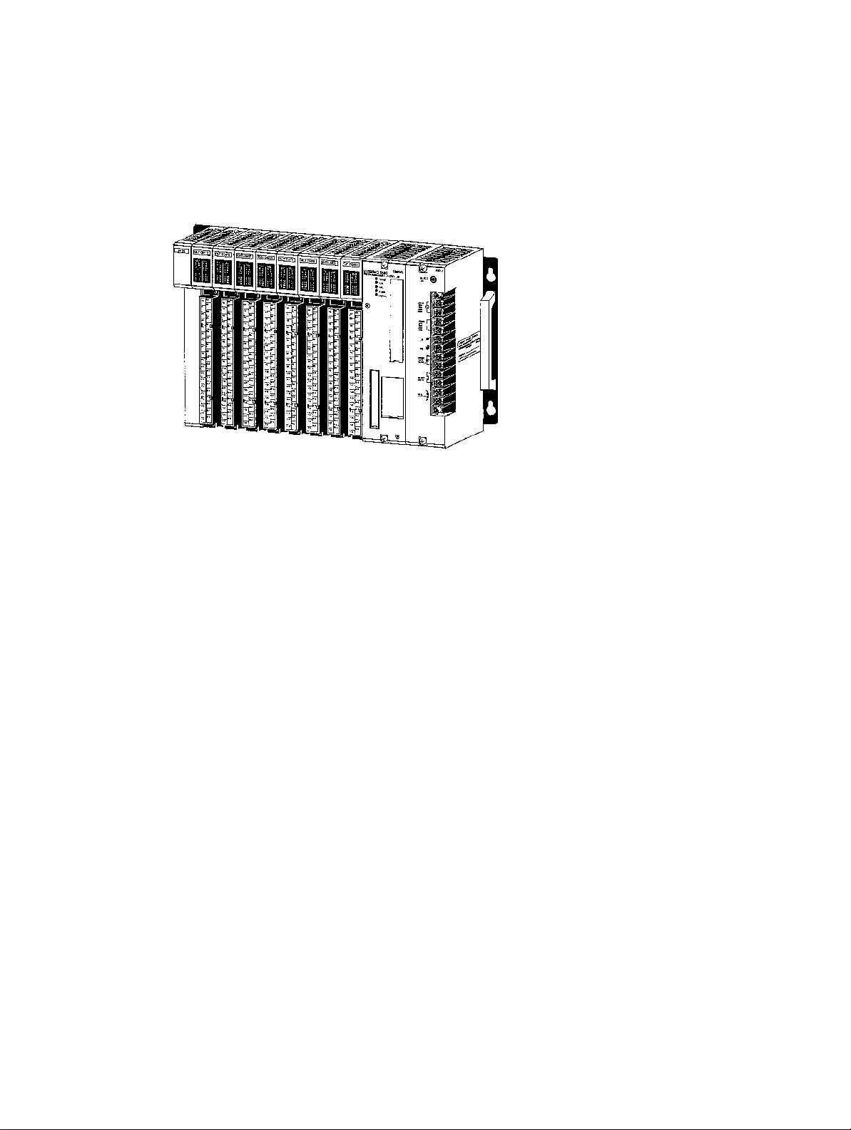
1-1 What is a Control System?
A Control System is the electronic equipment needed to control a particular
process. It may include everything from a process control computer, if one is
used, to the factory computer, down through the PCs (and there may be
many of them networked together), and then on down through the network to
the control components: the switches, stepping motors, solenoids, and sensors which monitor and control the mechanical operations.
Process Control Computer
Section 1Introduction
Factory Computer
PCs
PC PC PC
Control Components
A Control System can involve very large applications where many different
models of PC are networked together or it could be an application as small
as a single PC controlling a single output device.
2
Page 12
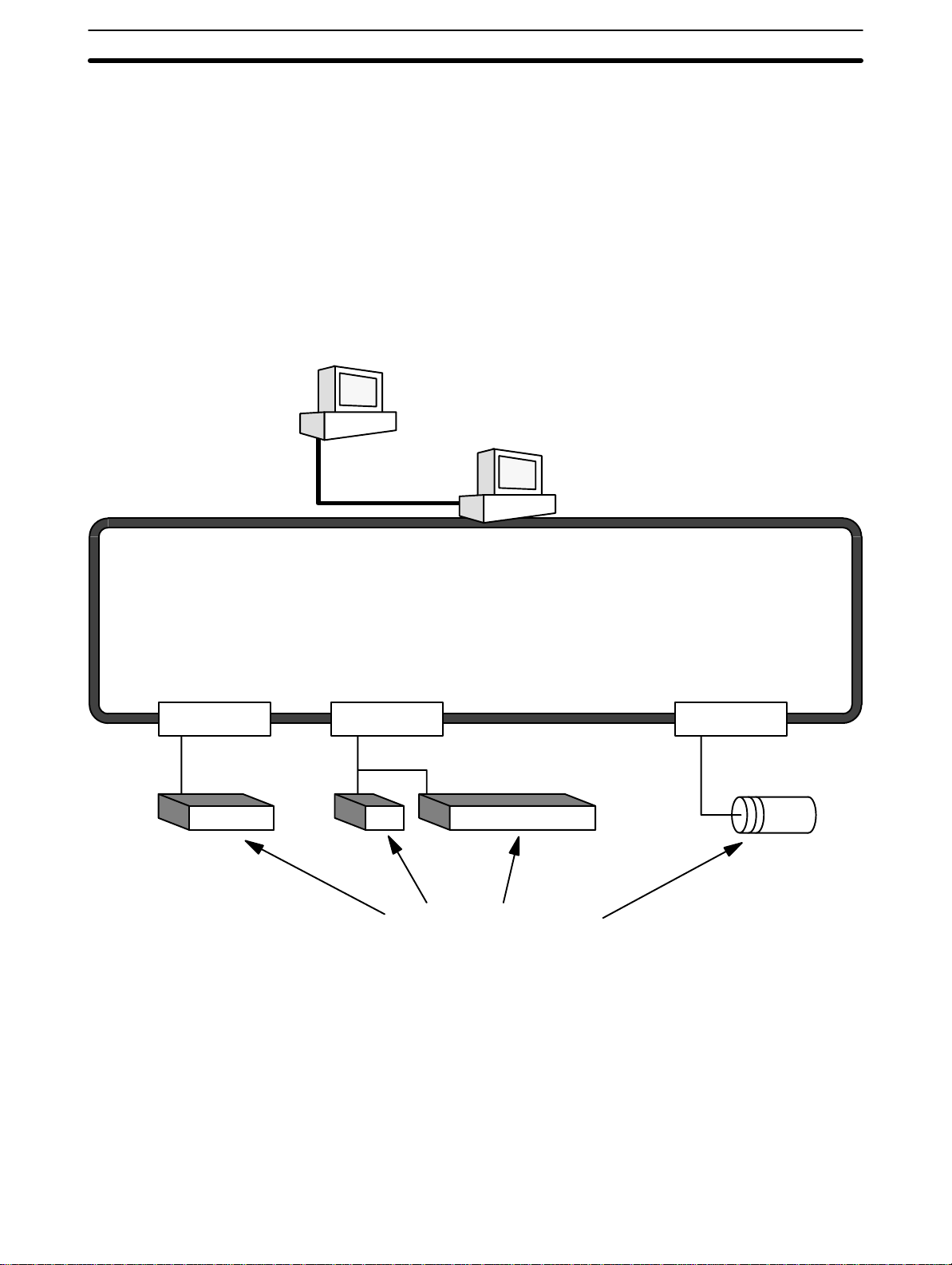
Position Control System
Section 1Introduction
Position Control Unit Input Unit
PC
Signal line for
Servomotor
driver control
Power
source
DC Servomotor
Driver
DC Servomotor
Power
source
DC Servomotor
Driver
DC Servomotor
Handheld
Programming
Console
Control panel
Control switch
In the typical Control System example shown above, a PC controls the movement of the workpiece bed across two horizontal axes using Limit Switches
and Servomotors to monitor and control movement.
1-2 The Role of the PC
The PC is the part of the Control System that directly controls the manufacturing process. According to the program stored in its memory, the PC accepts data from the input devices connected to it, and uses this data to monitor the controlled system. When the program calls for some action to take
place, the PC sends data to the output devices connected to it to cause that
action to take place. The PC may be used to control a simple, repetitive task,
or it may be connected to other PCs, or to a host computer in order to integrate the control of a complex process.
3
Page 13
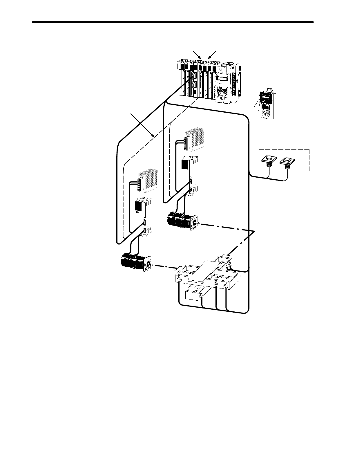
1-2-1 Input Devices
PCs can receive input from either automated or manual devices. The PC
could receive data from the user via a pushbutton switch, keyboard, or similar device. Automated input could come from a variety of devices: microswitches, timers, encoders, photosensors, and so on. Some devices, like the
Limit Switch shown below, turn ON or OFF when the equipment actually
makes contact with them. Other devices, like the Photoelectric Switch and
Proximity Switch shown below, use other means, such as light or inductance,
in order to get information about the equipment being monitored.
Section 1Introduction
Photoelectric Switch
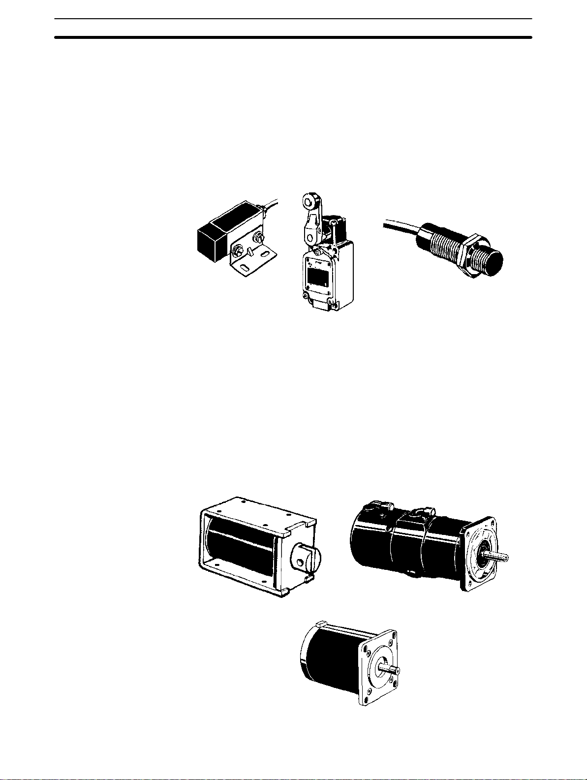
1-2-2 Output Devices
A PC can output to a myriad of devices for use in automated control. Almost
anything that you can think of could be controlled (perhaps indirectly) by a
PC. Some of the most common devices are motors, Solenoids, Servomotors,
Stepping Motors, valves, switches, indicator lights, buzzers, and alarms.
Some of these output devices, such as the motors, Solenoids, Servomotors,
Stepping Motors, and valves, affect the controlled system directly. Others,
such as the indicator lights, buzzers, and alarms, provide output to notify personnel.
Proximity Switch
Limit Switch
Solenoid
Stepping Motor
Servomotor
4
Page 14
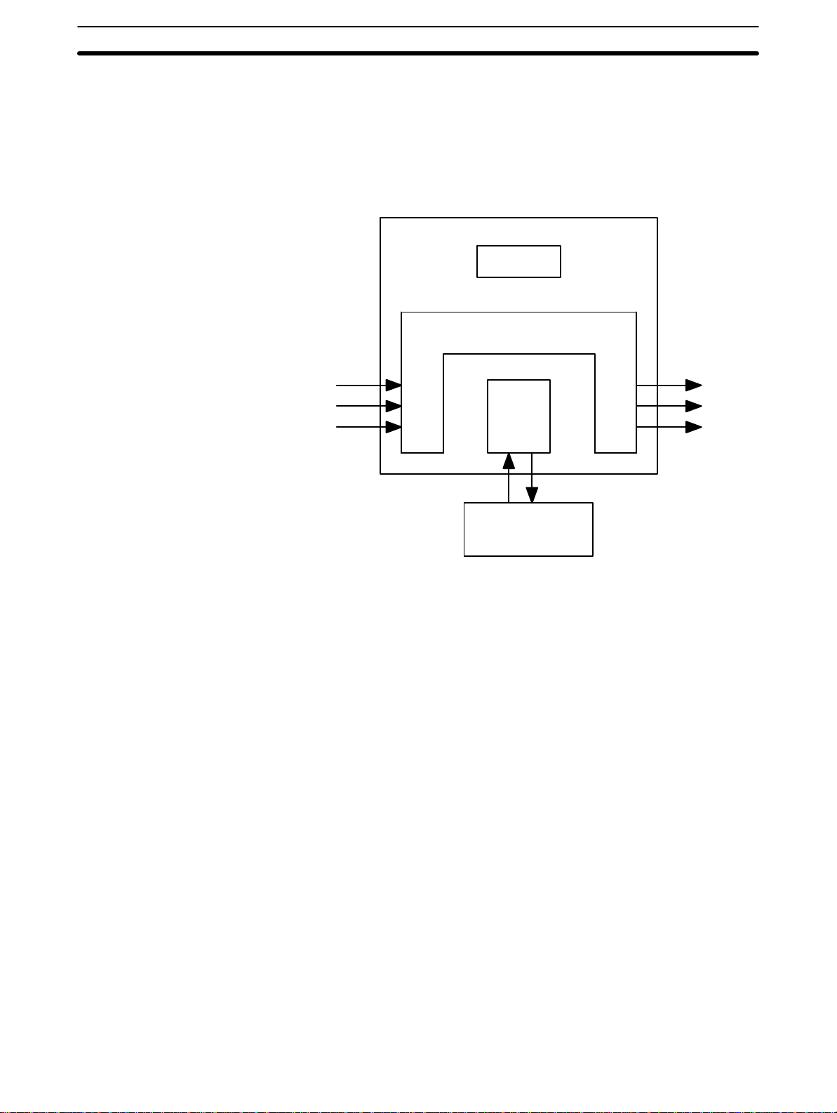
1-3 How Does a PC Work?
PCs operate by monitoring input signals and providing output signals. When
changes are detected in the signals, the PC reacts, through the user-programmed internal logic, to produce output signals. The PC continually cycles
the program in its memory to achieve this control.
Block Diagram of PC
Section 1Introduction
Power Supply
Memory
Scanning Cycle
Signals
from
switches,
sensors,
etc.
Input Output
CPU
Programming
Device
Signals
to Solenoids,
motors,
etc.
A program for your applications must be designed, and stored in the PC. This
program is then executed as part of the cycle of internal operations of the
PC.
When a PC operates, that is, when it executes its program to control an external system, a series of operations are performed inside the PC. These internal operations can be broadly classified into the following four categories:
1. Common (or overseeing) processes, such as watchdog timer operation
and testing the program memory.
2. Data input and output.
Cycle Time
3. Instruction execution.
4. Peripheral device servicing.
The total time required for a PC to perform all these internal operations is
called the cycle time. The flowchart and diagram on page 7 illustrate these
internal operations for a typical PC.
Timing is one of the most important factors in designing a Control System.
For accurate operations, it is necessary to have answers to such questions
as these:
• How long does it take for the PC to execute all the instructions in its memory?
5
Page 15

Section 1Introduction
• How long does it take for the PC to produce a control output in response to
a given input signal?
The cycle time of the PC can be automatically calculated and monitored, but
it is necessary to have an understanding of the timing relationships within the
PC for effective System design and programming.
6
Page 16
Section 1Introduction
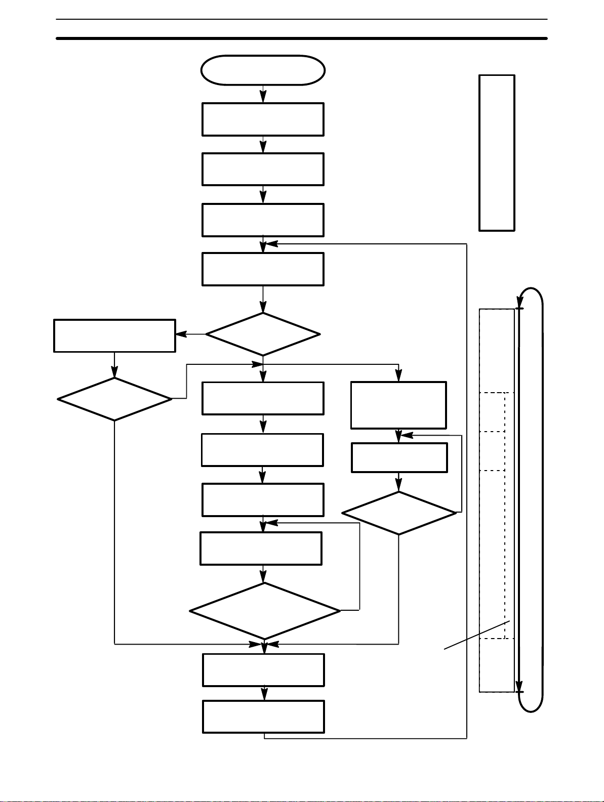
PC Operation
Flowchart
Sets error flag and
lights indicator
Power application
Clears data areas and re-
sets System counters
Checks I/O Unit connection
Resets watchdog timer
Checks hardware and
program memory
No
Check OK?
Initial
processing
on
power
application
Common
processes
Error or alarm?
Error
Alarm
IR data to Output Units
Processes Remote I/O
Resets watchdog timer
Services peripheral devices
Has the application program
been completely executed?
Yes
Resets watchdog timer
Resets watchdog
timer and application
program counter
Executes the program
End of Program?
No
Yes
Mathematical
processes
No
Out
refresh
Remote
I/O
processes
Servicing peripheral
devices
In refresh
PC
cycle
time
Data from Input
Units to IR Area
7
Page 17

SECTION 2
Description of All Components
2-1 CPU Rack 10 . . . . . . . . . . . . . . . . . . . . . . . . . . . . . . . . . . . . . . . . . . . . . . . . . . . . . . . .
2-2 CPU Power Supply 12 . . . . . . . . . . . . . . . . . . . . . . . . . . . . . . . . . . . . . . . . . . . . . . . . .
2-3 Expansion I/O Backplane 14 . . . . . . . . . . . . . . . . . . . . . . . . . . . . . . . . . . . . . . . . . . . .
2-4 I/O Power Supply 14 . . . . . . . . . . . . . . . . . . . . . . . . . . . . . . . . . . . . . . . . . . . . . . . . . .
2-5 I/O Control Unit 16 . . . . . . . . . . . . . . . . . . . . . . . . . . . . . . . . . . . . . . . . . . . . . . . . . . .
2-6 I/O Interface Unit 16 . . . . . . . . . . . . . . . . . . . . . . . . . . . . . . . . . . . . . . . . . . . . . . . . . .
2-7 I/O Units 16 . . . . . . . . . . . . . . . . . . . . . . . . . . . . . . . . . . . . . . . . . . . . . . . . . . . . . . . . .
2-8 Memory Packs 19 . . . . . . . . . . . . . . . . . . . . . . . . . . . . . . . . . . . . . . . . . . . . . . . . . . . .
9
Page 18
Introduction
2-1 CPU Rack
Section 2Description of All Components
This section provides information about the individual Units that make up the
C500 PC. First the names of all the parts of the PC are given, followed by
any details that apply to the Units that make up the PC. For a description of
how the Units fit together to become a PC, refer to
. For information about the model numbers of any of the parts described
tions
in this section, refer to
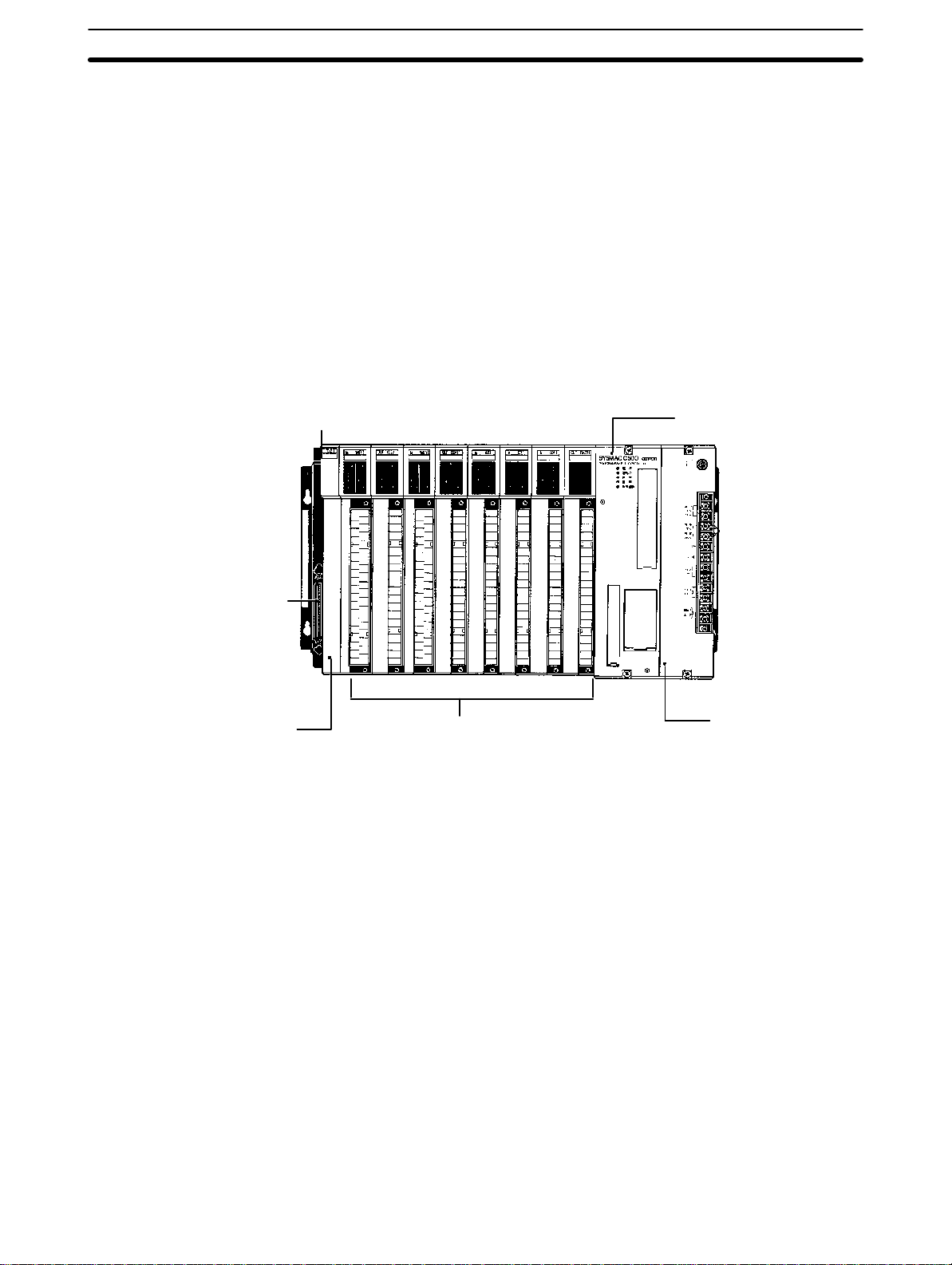
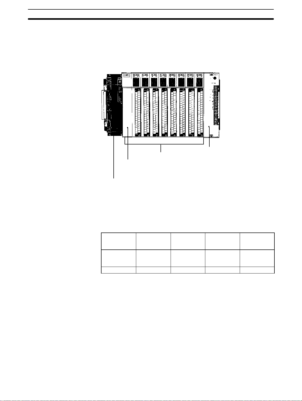
The following figure shows the names of all the parts of the CPU Rack.
There are seven models of CPU Racks available for the C500 PC. Choose a
Backplane with 3, 5 (2 models), 6, 8 (2 models), or 9 I/O slots, depending on
your application. Connect the CPU Backplane to an Expansion I/O Rack via
the Expansion I/O Connector.
Appendix C Standard Models
3-3 System Configura-
.
Expansion I/O Connector
Connects the CPU Rack
to an Expansion I/O
Rack. When not used,
cover with cap.
I/O Control Unit
An I/O Control Unit must be
mounted to the Rack in order to connect the CPU
Rack to an Expansion I/O
Rack.
Backplane
I/O Units
(3, 5, 6, 8, or 9 I/O Units depending on the Backplane
used)
CPU
CPU Power Supply
10
Page 19
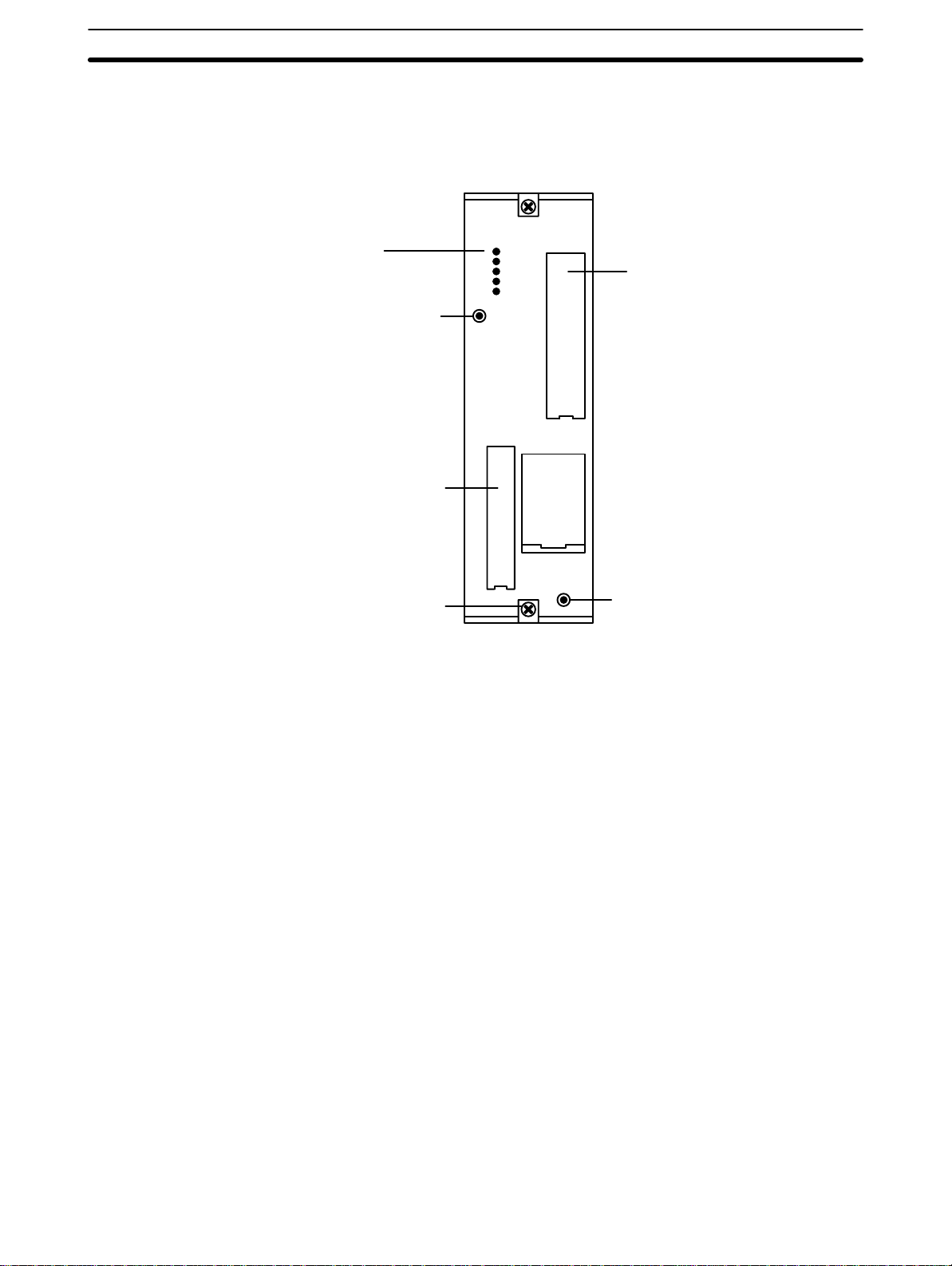
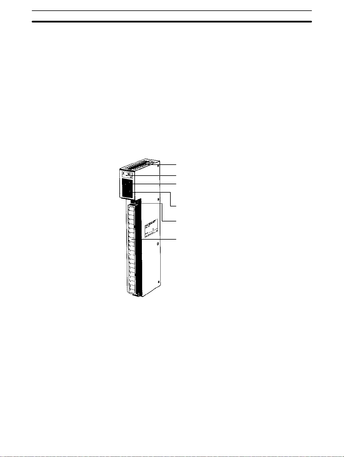
CPU
Section 2Description of All Components
The CPU executes the user program. The model available for the C500 PC
does not have a built-in Power Supply or Memory Pack. Choose the Power
Supply and memory pack suitable for your application. A peripheral device
connector and a memory pack compartment are provided.
Peripheral Device
Connector
Indicators
SYSMAC C500
PROGRAMMABLE CONTROLLER
POWER
RUN
ERR
ALARM
OUT INMB
OMRON
Memory Pack
and Battery
Compartment
Peripheral device
mounting screw
Peripheral device
•
connector cover
CPU mounting
screw
Peripheral device
mounting screw
The CPU is equipped with one connector for peripheral devices. A peripheral
device, such as the CPU-Mounting Programming Console, can be mounted
directly to the CPU and does not require a connecting cable. To mount the
CPU-Mounting Programming Console or any other peripheral device directly
to the CPU, follow these steps:
1. Detach the cover of the peripheral device connector with a standard
screwdriver.
2. Connect the CPU-Mounting Programming Console to the peripheral de-
vice connector.
3. To ensure a positive connection, secure the Programming Console to
the CPU by tightening the mounting screws located on the surface of the
CPU.
11
Page 20

2-2 CPU Power Supply
C
The CPU Power Supply is mounted to the rightmost slot of the CPU Rack.
Three models of Power Supplies are available: 100 to 120 VAC, 200 to 240
VAC, and 24 VDC. The following table summarizes the output capacity of the
three models and the current available for I/O Units mounted on the CPU
Rack.
Section 2Description of All Components
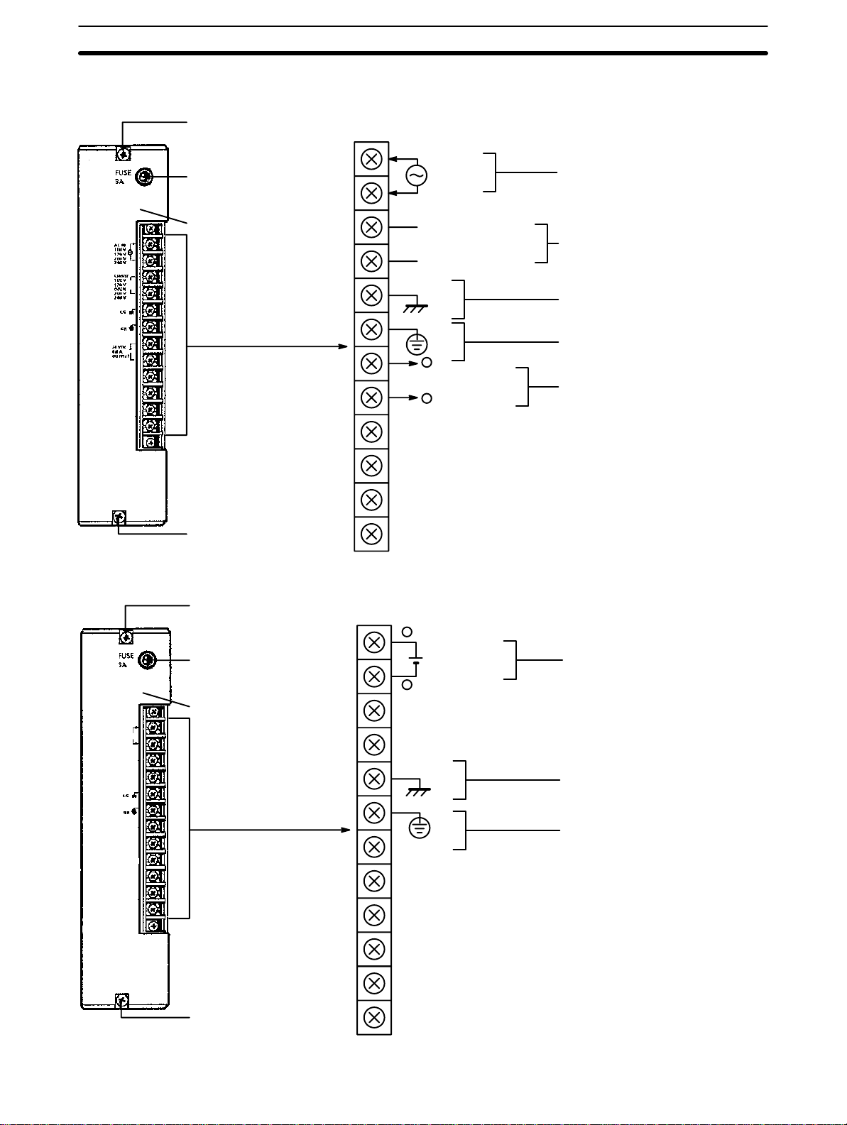
3G2A5-PS221-E
Mounting screw
Do not loosen this screw.
Fuse holder
Contains a MF61NR fuse
•
(3 A, 250 V, 6.35-dia. x32)
POWER indicator
Lights when power is supplied.
Mounting screw
Do not loosen this screw.
3G2A5-PS221-E
3G2A5-PS223-E
3G2A5-PS213-E 24 VDC 9 A 5 VDC 5 A Not provided
Note Be sure to keep the total power consumed by all the Units mounted
Terminals for
external connections
Model Supply Voltage Output
Capacity
100 to 120/
200 to 240 VA
(selectable)
7 A 5 VDC 5 A Provided
12 A 5 VDC 10 A Not provided
Available Current
for I/O Units
24 VDC Output
Terminal
on a Rack within the value stated in the table above. For example, do
not mount I/O Units with a total current consumption of 6 A to a Rack
supplied by a 7 A Power Supply. As shown in the table above, the
available current for I/O Units is only 5 A. For details concerning current consumption, refer to
AC input
Voltage selector
Short: 100 to 120 V
Open: 200 to 240 V
LG
GR
+
+
0.8 A, 24 VDC output
–
START input
RUN output
Section 4 System Connections
Connect a 100 to 120 VAC or 200 to
240 VAC power source.
Short these terminals to select 100 to
120 VAC. Open them to select 200 to
240 VAC.
Ground this terminal at a resistance of
less than 100
munity or prevent electric shock.
Ground this terminal at a resistance
of less than 100
shock.
Use these terminals to supply power
to DC Input Units. Use a separate
Power Supply if the I/O Unit requires
more than 0.8 A. If a current higher
than 0.8 A is output, the PC stops.
These terminals are short-circuited as
a factory-set condition. Remove the
short-circuit bracket to start or stop
the PC with an external signal. Normally, leave them short-circuited.
These terminals are turned ON during RUN operation.
Ω to improve noise im-
.
Ω to prevent electric
12
Page 21

3G2A5-PS223-E
Section 2Description of All Components
Mounting screw
Do not loosen this screw.
•
3G2A5-PS213-E
Fuse holder
Contains a MF61NR fuse
(3 A, 250 V, 6.35-dia. x32)
POWER indicator
Lights when power is supplied.
Terminals for
external connections
Mounting screw
Do not loosen this screw.
Mounting screw
Do not loosen this screw.
AC input
Voltage selector
Short: 100 to 120 V
Open: 200 to 240 V
LG
GR
START input
RUN output
+
Connect a 100 to 120 VAC or 200
to 240 VAC power source.
Short these terminals to select 100
to 120 VAC. Open them to select
200 to 240 VAC.
Ground this terminal at a resistance of less than 100
prove noise immunity or prevent
electric shock.
Ground this terminal at a resis-
tance of less than 100
vent electric shock.
24 VDC output terminals are not
provided.
These terminals are short-circuited
as a factory-set condition. Remove
the short-circuit bracket to start or
stop the PC with an external signal.
Normally, leave them shortcircuited.
These terminals are turned ON
during RUN operation.
Ω to im-
Ω to pre-
Fuse holder
Contains a MF61NR fuse
•
(3 A, 250 V, 6.35-dia. x32)
POWER indicator
Lights when power is supplied.
Terminals for
external connections
Mounting screw
Do not loosen this screw.
24 VDC input
-
LG
GR
START input
RUN output
Connect a 24 VDC power source
(2.3 A min.)
Ground this terminal at a resistance
of less than 100
immunity or prevent electric shock.
Ground this terminal at a resistance
of less than 100
tric shock.
24 VDC output terminals are not
provided.
These terminals are short-circuited
as a factory-set condition. Remove
the short-circuit bracket to start or
stop the PC with an external signal.
Normally, leave them shortcircuited.
These terminals are turned ON during RUN operation.
Ω to improve noise
Ω to prevent elec-
13
Page 22
2-3 Expansion I/O Backplane
The Expansion I/O Backplane shown in the following diagram, can be used
to expand the C500 PC. An Expansion I/O Rack is just like a CPU Rack, except a CPU is not mounted. However, a Power Supply is needed for each
Expansion I/O Rack. There are three models of Expansion I/O Backplane
available.
I/O Units
I/O Interface Unit
An I/O Interface Unit must be mounted to an Expansion I/O Rack in order to connect the Expansion I/O Rack to another Expansion I/O Rack.
Expansion I/O Backplane
Section 2Description of All Components
Expansion I/O Power Supply
2-4 I/O Power Supply
Just as a Power Supply must be mounted to the CPU Rack, a Power Supply
must also be mounted to each Expansion I/O Backplane. There are two
Power Supplies available; 100 to 120/200 to 240 VAC and 24 VDC, both of
which are explained below. For details, refer to
Model Supply Voltage Output
3G2A5-PS222-E 100 to 120/200
3G2A5-PS212-E 24 VDC 7 A 5 VDC 6.5 A Not provided
Note Be sure to keep the total power consumed by all the Units mounted
on a Rack within the value stated in the table above. For example, do
not mount I/O Units with a total current consumption of 7A to a Rack
supplied by a 7 A Power Supply. As shown in the table above, the
available current for I/O Units is only 6.5 A. For details concerning
current consumption, refer to
to 240 VAC
(selectable)
Appendix B Specifications
Available
Capacity
7A 5 VDC 6.5 A Provided
Current for I/O
Units
240 VDC
Output
Terminal
Section 4 System Connections
.
.
14
Page 23
3G2A5-PS222-E
Mounting screw
Do not loosen this screw.
Section 2Description of All Components
Fuse holder
Contains a MF61NR fuse
•
(3 A, 250 V, 6.35-dia. x32)
POWER indicator
Lights when power is supplied.
Mounting screw
Do not loosen this screw.
3G2A5-PS212-E
Terminals for
external connections
AC input
Voltage selector
Short: 100 to 120 V
Open: 200 to 240 V
LG
GR
+
0.8 A, 24 VDC output
-
Connect a 100 to 120 VAC or 200 to
240 VAC power source
Short these terminals to select 100 to
120 VAC. Open them to select 200 to
240 VAC.
Ground this terminal at a resistance
of less than 100
immunity or prevent electric shock.
Ground this terminal at a resistance
of less than 100
shock.
Use these terminals to supply power
to DC Input Units. Use a separate
Power Supply if the I/O Unit operate
on more than 0.8 A. If a current higher
than 0.8 A is output, the PC stops.
These terminals are used to supply
external DC Input Units. If the Unit requires more than 0.8 A a separate
supply must be used. The PC shuts off
automatically if a current of more than
0.8 A is drawn from the supply.
Ω to improve noise
Ω to prevent electric
Mounting screw
Do not loosen this screw.
Fuse holder
Contains a MF61NR fuse
•
(3 A, 250 V, 6.35-dia. x32)
POWER indicator
Lights when power is supplied.
Terminals for
external connections
Mounting screw
Do not loosen this screw.
+
-
24 VDC input
LG
GR
Connect a 24-VDC power source (2.3
A min.)
Ground this terminal at a resistance
of less than 100
immunity or prevent electric shock.
Ground this terminal at a resistance
of less than 100
shock.
Ω to improve noise
Ω to prevent electric
15
Page 24
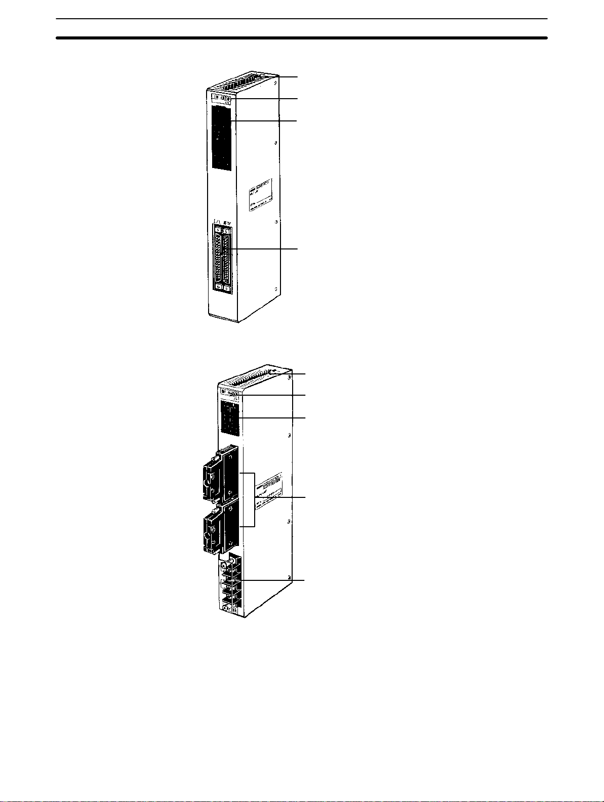
2-5 I/O Control Unit
An I/O Control Unit must be mounted to the CPU Rack in order to connect
the CPU Rack to an Expansion I/O Rack. An I/O Control Unit can be
mounted even if no Expansion I/O Rack is used.
2-6 I/O Interface Unit
An I/O Interface Unit is needed on each Expansion I/O Rack, in order to expand the PC. If there is not an I/O Interface Unit on each Expansion I/O
Rack, data communication cannot take place. The I/O Interface Unit is
mounted to the leftmost I/O position on the Expansion I/O Backplane.
2-7 I/O Units
I/O Units come in 5 shapes; A-shape, B-shape, C-shape, D-shape, and Eshape. Refer to
A-shape
Appendix B Specifications
Mounting screw
Provided at top and bottom
Nameplate
Fuse blowout alarm indicator
Provided on OD411/OA121/
OD217/OA222
Section 2Description of All Components
for the dimensions of each Unit.
I/O indicators
Indicate ON/OFF status points
Terminal block mounting screw
Provided at top and bottom
20-terminal terminal block
Removable
16
Page 25
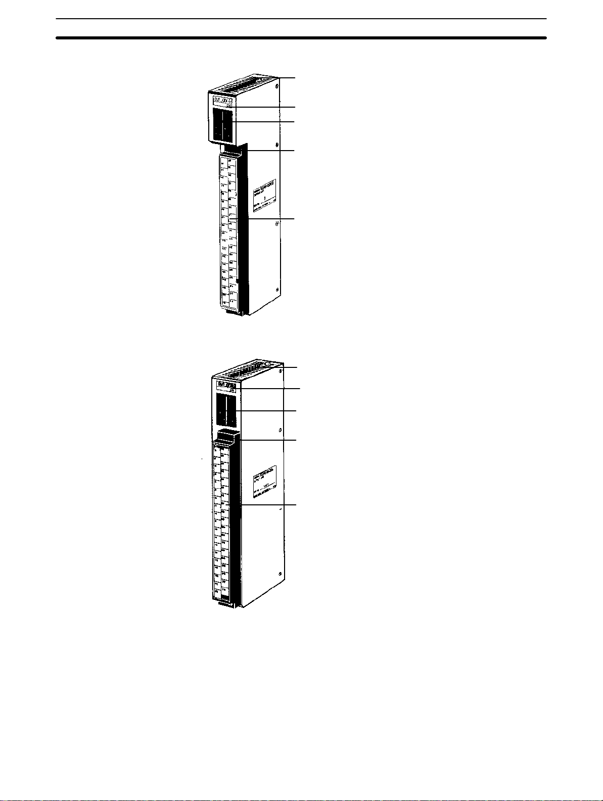
B-shape
Section 2Description of All Components
Mounting screw
Provided at top and bottom
Nameplate
I/O indicators
Indicate ON/OFF status of I/O
signal
Terminal block mounting screw
Provided at top and bottom
38-terminal terminal block
Removable
C-shape
Mounting screw
Provided at top and bottom
Nameplate
I/O indicators
Indicate ON/OFF status of points
Terminal block mounting screw
Provided at top and bottom
38-terminal terminal block
Removable
17
Page 26
D-shape
Section 2Description of All Components
Mounting screw
Provided at top and bottom
Nameplate
I/O indicators
Indicate ON/OFF status of points
Two 40-terminal terminal
block connectors
Removable
E-shape
Mounting screw
Provided at top and bottom
Nameplate
I/O indicators
Indicate ON/OFF status of points
Two 24-terminal terminal block plugs
4-terminal terminal block
18
Page 27

2-8 Memory Packs
The Memory Pack fits into the slot located on the left side of the CPU. Because the Memory Pack is not provided with the PC upon delivery, a Memory
Pack must be selected and installed in the CPU. There are two Memory
Packs available, either RAM or ROM, that can be used in the C500H PC.
RAM Pack
Data can be randomly written to and read from the RAM Pack, making it possible to enter your own program into the CPU. However, because this is not a
fixed program, the memory of the RAM Pack is erased when power is not
supplied to the CPU or when the RAM Pack is removed from the CPU.
Caution Do not remove the battery in the CPU when the RAM Pack has been removed
!
from the CPU.
Section 2Description of All Components
CHIP 0 CHIP 1 CHIP 264 128
RAM Pack
Two models of RAM Packs are available, which vary in memory capacity:
16K, and 24K words. Refer to
bers.
Using a Programming Console, execute FUN (01) and a search operation to
check the amount of memory available.
Appendix C Standard Models
for model num-
19
Page 28
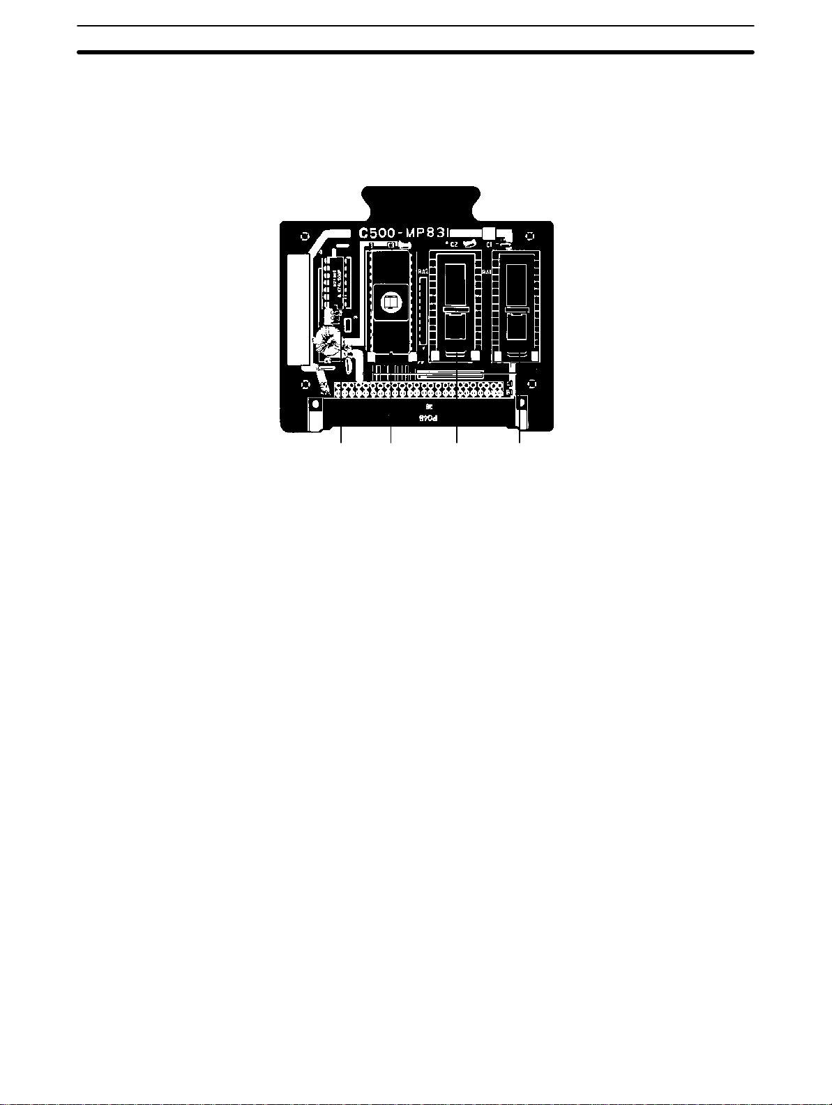
ROM Pack
Section 2Description of All Components
Data contained in the ROM Pack is stored on EPROM chips and cannot be
altered or erased during the CPU’s operation. Write the user’s program to the
EPROM chips and mount the chips (3 max.) on the ROM chip. The entire
pack is installed in the CPU. Once the data is written to the chip the data will
not be lost when the power to the PC is OFF.
CHIP 0 CHIP 1 CHIP 264 128
RAM Pack
20
Page 29

SECTION 3
Assembly
3-1 Mounting the Units 22 . . . . . . . . . . . . . . . . . . . . . . . . . . . . . . . . . . . . . . . . . . . . . . . . .
3-2 Memory Packs 25 . . . . . . . . . . . . . . . . . . . . . . . . . . . . . . . . . . . . . . . . . . . . . . . . . . . .
3-3 System Configurations 27 . . . . . . . . . . . . . . . . . . . . . . . . . . . . . . . . . . . . . . . . . . . . . .
21
Page 30
Introduction
When we speak of a PC, we usually think of it as a single object. But actually
even the simplest PCs are usually composed of several different devices. In
fact a single PC can be physically spread throughout a building, but we still
call it one PC.
In this section, we will start with a Backplane and use all the Units discussed
Section 2 Description of All Components
in
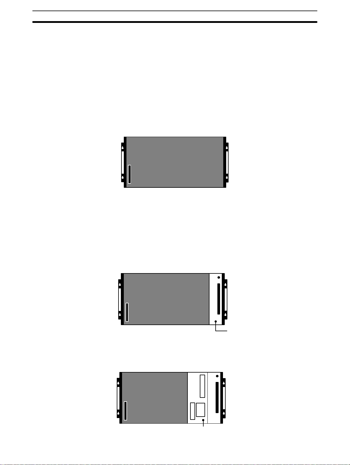
3-1 Mounting the Units
There is no single Unit that can be said to constitute a Rack PC. To build a
Rack PC, we start with a Backplane. The Backplane for the C500 is shown
below.
Section 3Assembly
to build a PC.
C500 Backplane
The Backplane is a simple device having two functions. The first is to provide
physical support for the Units to be mounted to it. The second is to provide
the connectors and electrical pathways necessary for connecting the Units
mounted to it.
The first device we will add to the Backplane is a Power Supply. The Power
Supply fits into the rightmost position on the Backplane and provides electricity at the voltages required by the other Units of the PC. It can also be used
to power devices other than the PC if necessary.
Power Supply
The core of the PC is the CPU. The CPU contains the program consisting of
the series of steps necessary for the control task. The CPU fits into the position directly to the left of the Power Supply.
22
CPU
Page 31

Section 3Assembly
Unlike the CPU of the Package-type PC, the CPU of the Rack PC has no I/O
points built in. So, in order to complete this kind of PC we need to mount one
or more I/O Units to the Backplane. Mount the I/O Units to the Backplane by
pressing the I/O Unit firmly into position, making sure the connectors are
properly mated. Secure the Unit by tightening the mounting screws located
on the top and bottom of the Unit.
Mounting screws
Provided at the top and
bottom of the Unit
Connector
Make sure the connectors
are properly mated.
The figure below shows one I/O Unit mounted directly to the left slot of the
CPU Rack.
I/O Unit
I/O Units are where the control connections are made from the PC to all the
various input devices and output devices. As you can see from the figure,
there is still some space available on the right side of the Backplane. This
space is for any additional I/O Units that may be required.
The figure above shows a total of eight I/O Units mounted to the Backplane.
Backplanes are available in different lengths, and can hold a different number
of I/O Units accordingly. Of course, not all I/O Units look exactly alike, but the
ones in the figure show their typical appearance. This configuration of Backplane, Power Supply, CPU, and I/O Units is called a CPU Rack. This term
refers to the Backplane and all the Units mounted to it. However, if we want
to include more than eight I/O Units in our configuration we can add an addi-
23
Page 32

Section 3Assembly
tional Backplane. First, though, we have to mount an I/O Control Unit to the
leftmost slot of the CPU Rack.
I/O Control Unit
Now we can use a cable to connect the CPU Rack to another Backplane.
This Backplane has a Power Supply and I/O Units mounted to it, but it has no
CPU of its own. The additional Backplane must also have an I/O Interface
Unit mounted to its leftmost position. This configuration of additional Backplane, Power Supply, I/O Units, and I/O Interface Unit is called an Expansion
I/O Rack.
CPU Rack
Expansion I/O Rack
I/O Interface Unit
The CPU Rack and Expansion I/O Rack shown above are connected by a
cable. Remember that this whole configuration is still referred to as one PC.
It is possible to keep adding Expansion I/O Racks in this way until the maximum number of I/O points for the system is reached. Each Expansion I/O
Rack needs an I/O Interface Unit.
24
Page 33

3-2 Memory Packs
y
pg
128
64
8
128
The CPU has a removable Memory Pack that stores the user program. Two
Memory Packs are available, in either RAM or ROM. You can write your own
program into the RAM Pack or you can copy a program that has already
been written to an EPROM chip and mount it in the ROM Pack. The EPROM
Chip must be mounted to the PROM Writer in order for the program to be
written to it. Then the EPROM Chip must be mounted to the ROM Pack.
Mounting the EPROM
Chip to the ROM Pack
Depending on the amount of memory required for your application, use 1, 2,
or 3 chips. Refer to
EPROM chips.
Using the diagram and the table below as a reference, mount the EPROM
chips to the correct IC sockets.
Appendix B Specifications
Section 3Assembly
for specifications of the
Memory size Jumper setting
8K bytes
16K bytes
24K bytes
16K bytes
24K bytes
How to Install the
Memory Pack
Caution Do not attempt to install the Memory Pack in the CPU while the power to the PC
!
CHIP 0 CHIP 1 CHIP 264 128
RAM Pack
The table below summarizes the programming capacity.
IC Socket
CHIP 0 CHIP 1 CHIP 2
128
12
64
2764 – –
2764 2764 –
2764 2764 2764
27128 – –
27128 – 2764
Take the following steps to install the Memory Pack in the CPU.
1. Turn the power to the PC OFF.
is ON. Doing so may cause data to be lost, or may damage the CPU or Memory
Pack.
25
Page 34

Section 3Assembly
2. Using a standard screwdriver, remove the Memory Pack compartment
cover located on the front panel of the CPU. Push in the latch on the
cover and slide the cover upward.
SYSMAC C500
PROGRAMMABLE CONTROLLER
POWER
RUN
ERR
ALARM
OUT INMB
OMRON
•
Use a standard screwdriver to remove the Memory
Pack compartment cover.
3. Insert the Memory Pack (component side facing left) into the Memory
compartment. When the Unit is almost completely inserted into the CPU,
there may be a slight resistance as the Memory Pack connector mates
with the connector inside the CPU. Continue pushing on the Memory
Pack until it is inserted completely into the CPU.
Memory Unit guide
Memory Pack
(ROM or RAM Pack)
How to Remove the
Memory Pack
26
4. Reattach the memory compartment cover.
Follow the steps below to remove the Memory Pack from the CPU.
1. Turn the power to the PC OFF.
2. Using a standard screwdriver, remove the Memory Pack compartment
cover located on the front panel of the CPU. Push in the latch on the
cover and slide the cover upward.
3. Pull the Memory Pack up and out.
Page 35

Note Memory in the RAM Pack is erased when the Memory Pack is
removed from the CPU and when the CPU Unit is removed from
the Rack.
3-3 System Configurations
The following figure shows an assembled C500 CPU Rack and one Expansion I/O Rack. When three Expansion I/O Racks are connected to a CPU
Rack, a maximum of 512 I/O points are available. (Include the Remote I/O
Units)
I/O Control Unit
Section 3Assembly
CPU
CPU
Power Supply
CPU Rack
Where I/O Units Can Be
Mounted
Connecting Cable
I/O Interface Unit
Programming
Console
Expansion I/O
Power Supply
The table below summarizes the Units that can be used in the systems described in this manual.
Special I/O Units The number of Special I/O Units that can be used depends
upon the number of points available and the number of
points the Special I/O Unit requires.
Host Link Units Up to one Host Link Units can be mounted. Only one
I/O Units Standard I/O Units are available with 16, 32, or 64 points.
Memory Packs RAM or ROM Packs are available. The ROM Pack requires
Remote I/O Master
Unit
Rack-Mounting Host Link Unit can be mounted to the CPU
Rack. A CPU-Mounting Host Link Unit can also be mounted
directly to the CPU. Host Link Units cannot be mounted to
Expansion I/O Racks.
However, these Units cannot be mounted when the
SYSMAC Net Link Unit is mounted.
Refer to
a separately available EPROM chip.
Up to four Remote I/O Master Units can be mounted to both
the I/O Rack and the Expansion I/O Racks. When the
Remote I/O Unit is mounted to a Rack, a Rack number must
be set so that the CPU can identify the Remote I/O Unit.
Mount the Remote I/O Slave Unit to the leftmost position
(the I/O Interface Unit position) on the Slave Rack. For
details, refer to the C500 Operation Manual.
Section 2 Description of All Components
for details.
27
Page 36

Section 3Assembly
The following table summarizes specific Units that can and cannot be
mounted in the CPU and Expansion Racks and the number that can be used
in each PC. For more information about the Units, refer to the
tion Manual
Unit CPU Rack Expansion Rack
16-, 32-, 64-point I/O YES YES
Special I/O YES YES
I/O Link YES YES
PC Link YES (2 max.)
Host Link YES (2 max.)* NO
SYSMAC Net Link YES (1 max.) NO
Remote I/O Master YES YES
Remote I/O Slave NO YES
*One Rack-mounting Host Link Unit can be mounted to the CPU Rack and one CPU-mounting Host Link Unit can be mounted directly to
the CPU Unit.
.
NO
Notes 1. The Position Control Unit and the PID Unit each require two I/O
slots on the CPU Rack and the Expansion I/O Racks
2. The following Units can only be mounted to one of the three or
five rightmost slots on the CPU Backplane, depending on which
Backplane is used.
PC Link
Host Link
SYSMAC Net Link
C500 Opera-
3. When two or more PCs are linked by the PC Link Unit, a maximum of 32 PC Link Units can be used (linking 31 PCs), in any
number of subsystems.
4. SYSMAC Net Link and Host Link cannot be mounted simultaneously.
28
Page 37

SECTION 4
System Connections
4-1 Current Consumption 30 . . . . . . . . . . . . . . . . . . . . . . . . . . . . . . . . . . . . . . . . . . . . . . .
4-2 I/O Connections 33 . . . . . . . . . . . . . . . . . . . . . . . . . . . . . . . . . . . . . . . . . . . . . . . . . . .
29
Page 38

Introduction
y
In the preceding sections we have covered all the parts of a PC and how they
should be assembled. This section provides detailed information on PC connections.
4-1 Current Consumption
The Power Supplies are limited in the total current they can supply to I/O Units.
The following table shows the maximum currents allowed.
Power Supplies
Unit Model Output Capacity Current Available
CPU Power Supply
I/O Power Supply
Note Do not exceed the maximum current ratings for each of the voltages
supplied by any single Unit listed above. In addition, do not exceed
the total maximum power output for any single Unit listed above. Refer to the tables on the following page for the current consumption of
individual I/O Units.
3G2A5-PS221-E
3G2A5-PS211-E
3G2A5-PS213-E 9 A 5 VDC
3G2A5-PS223-E 12 A 5 VDC 10 A
3G2A5-PS222-E
3G2A5-PS212-E
7 A 5 VDC
7 A 5 VDC 6.5 A
5 A
Section 4System Connections
for I/O Units
Input Units
Unit Model Current
DC Input
AC Input
TTL Input 3G2A5-ID501CN 0.2
AC/DC Input
3G2A5-ID112 0.01
3G2A5-ID114 0.34
3G2A5-ID213 0.02
3G2A5-ID215 0.16
3G2A5-ID218 0.16
3G2A5-ID218CN 0.2
3G2A5-ID212 0.3
3G2A5-ID219 0.34
3G2A5-IA121 0.01
3G2A5-IA222 0.012
3G2A5-IA223 0.06
3G2A5-IA122 0.06
3G2A5-IM211 0.01
3G2A5-IM212 0.2
Consumption (A)
30
Page 39

Output Units
Unit Model Current
Contact Output
Transistor Output
Triac Output
TTL Output C500-OD501CN 0.25
DC Input/Transistor Output
Unit
Dummy I/O 3G2A5-DUM01 0.035
3G2A5-OC221 0.1
3G2A5-OC223 0.1
3G2A5-OC224 0.2
3G2A5-OD411 0.16
3G2A5-OD215 0.2
3G2A5-OD412 0.23
3G2A5-OD212 0.23
3G2A5-OD211 0.3
3G2A5-OD213 0.46
3G2A5-OD217 0.16
C500-OD218 0.23
C500-OD219 0.16
3G2A5-OD415CN 0.23
3G2A5-OA121 0.3
3G2A5-OA222 0.3
3G2A5-OA223 0.45
C500-OA225 0.2
C500-OA226 0.45
3G2A5-MD211CN 0.26
Section 4System Connections
Consumption (A)
31
Page 40

Special I/O Units
g
y
Unit Model Current
Consumption (A)
A/D Converter Input
D/A Converter Output
High-speed Counter
Magnetic Card Reader 3G2A5-MGC01 1.0
PID 3G2A5-PID01-E 1.4
Position Control
ASCII C500-ASC04 0.5 each
ID Sensor
Ladder Program I/O 3G2A5-LDP01-V1 0.8
File Memory
Cam Positioner C500-CP131 0.35
3G2A5-AD001 to- AD005 0.3 each
3G2A5-AD006
3G2A5-AD007
C500-AD101 0.88
C500-AD501 1.2
3G2A5-DA001 to -DA005 0.55 each
C500-DA101 1.3
3G2A5-CT001 0.3
3G2A5-CT012 0.55
C500-CT041 1.0
3G2A5-NC103-E
3G2A5-TU001-E
3G2A5-NC111-EV1
3G2A5-TU001-E
3G2A5-NC221-E
3G2A5-TU001
C500-IDS01-V2/IDS02-V1
C500-IDS21/IDS22
C1000H-FMR11
C1000H-FMR21
0.75 each
Total 1.4
Total 1.0
Total 1.3
0.4 each
0.35 each
Section 4System Connections
Link Units and Remote
I/O Units
Unit Model Current
I/O Link 3G2A5-LK010-(P)E 0.6
PC Link C500-LK009-V1 0.9
Host Link
Optical Remote I/O Master 3G2A5-RM001-(P)EV1 0.7
SYSMAC Net Link C500-SNT31-V4 1.4
Wired Remote I/O Master C500-RM201 0.3
C500-LK103 (-P)
C500-LK203
1.0 each
Consumption (A)
32
Page 41

4-2 I/O Connections
Connect the I/O Devices to the I/O Units using AWG (cross-sectional area:
0.3 mm
tional area: 0.3 to 0.75 mm
screws with 3.5-mm diameter heads and self-raising pressure plates. Connect
the lead wires to the terminals as shown. Always use solderless (crimp) terminals. Tighten the screws to a torque of 0.8 N S m.
Use M3.5 self-rising screws for the terminal screws of the Power Supply Units.
Always attach crimp terminals to the ends of the lead wires before attaching
them to the terminals. Never attach loose or twisted wires.
2
) for 19-terminal terminal blocks and AWG 22 to lead wire (cross-sec-
Section 4System Connections
2
) for 10-terminal terminal blocks. The terminals have
Tighten the screws on the terminal block to a torque of 0.8 N S m. Use crimp terminals for M3.5 screws of the dimensions shown below.
7 mm max.7 mm max.
33
Page 42

Terminal Block
Section 4System Connections
The terminal block of an I/O Unit can be removed by loosening the mounting
screws. You do not have to remove the lead wires from the terminal block in order to remove it from an I/O Unit.
Note Putting I/O Lines and high-tension lines or power lines in the same
duct or conduit may cause the I/O Lines to be affected by noise. This
may cause a malfunction in the I/O Unit or may cause damage to the
I/O Unit or I/O devices.
Terminal block mounting screws
Loosen the terminal block mounting screws to remove
the terminal block from the I/O Unit. Make sure the
mounting screws on the terminal block are tightened after wiring is complete, and the terminal block is remounted to the I/O Unit.
Wiring Examples
DC Input Units
Note When a Triac Output Unit is used to drive a low-current load, the load
may not turn completely OFF due to a leakage current. To compensate for the leakage current, connect a bleeder resistor in parallel
with the load.
The following are examples of how to connect I/O devices to I/O Units. During
wiring, work slowly and carefully. If an input device is connected to an Output
Unit, damage may result. Check all I/O devices to make sure they meet the
specifications (refer to
Appendix B Specifications
). Be sure to allow for leakage
current and load inductance.
Contact output
IN DC input
COM
When using the following configurations, the sensor and Input Unit should receive their power from the same supply.
34
Page 43

NPN current output
Current
regulator
NPN open-collector output
PNP current output
+
Output
+
Output
7 mA
0 V
+
Output
7 mA
0 V
Section 4System Connections
IN DC input
COM
Sensor
Power
Supply
IN DC input
COM
Sensor
Power
Supply
IN AC/DC input
AC Input
7 mA
0 V
Contact output
AC Switching
Prox.
switch
main
circuit
COM
IN AC input
COM
IN AC input
COM
Note If a reed switch is used as the input contact of the AC Input Unit, the
reed switch must have a permissible current capacity of 1 A minimum, otherwise contact weld may result due to inrush current.
Output Units
A fuse placed in the output circuit will protect the output element, circuit board,
etc., in the event of a short circuit in the output circuit.
OUT
COM
Relay,
solenoid, etc.
+
35
Page 44

SECTION 5
Installation Environment
5-1 Cooling 38 . . . . . . . . . . . . . . . . . . . . . . . . . . . . . . . . . . . . . . . . . . . . . . . . . . . . . . . . . .
5-2 Mounting Requirements 38 . . . . . . . . . . . . . . . . . . . . . . . . . . . . . . . . . . . . . . . . . . . . .
5-3 Duct Work 40 . . . . . . . . . . . . . . . . . . . . . . . . . . . . . . . . . . . . . . . . . . . . . . . . . . . . . . .
5-4 Preventing Noise 41 . . . . . . . . . . . . . . . . . . . . . . . . . . . . . . . . . . . . . . . . . . . . . . . . . .
37
Page 45

Introduction
Caution Static electricity can cause damage to PC components. Your body can carry an
!
5-1 Cooling
Clearance Between
Racks
Section 5Installation Environment
This section details the necessary environment and conditions for installation
of the PC. For specific instructions on mounting Units and wiring for I/O and
power, refer to
electrostatic charge, especially when the humidity is low . Before touching the PC
be sure to first touch a grounded metallic object, such as a water pipe, in order to
discharge any static build-up.
There are two points to consider in order to ensure that the PC does not
overheat. The first is the clearance between the Racks, and the second is
installation of a cooling fan.
The Racks need to have sufficient room between each other to allow for I/O
wiring, and additional room to ensure that the I/O wiring does not hamper
cooling. However, the Racks must be mounted so that the length of the connecting cable does not exceed 2 m, and the total length of the Connecting
Cables between all Racks does not exceed 12 m. For details about cable
lengths, refer to
120 mm should be left between any two Racks.
Section 3-3 System Configurations
Appendix C Standard Models
and
4-2 I/O Connections
. As a general rule, about 70 to
.
Cooling Fan
A cooling fan is not always necessary, but may be needed in some installations. Try to avoid mounting the PC in a warm area, or over a source of heat.
A cooling fan is needed if the ambient temperature may become higher than
that specified (refer to
enclosure install a cooling fan, as shown in the following diagram, to maintain
the ambient temperature within specifications.
Louver
Appendix B Specifications
PC
5-2 Mounting Requirements
The PC consists of from one to nine Racks. Each Rack must be mounted
vertically, that is with the printing on the front panels oriented as it would normally read. The Racks should be mounted one above the other with the CPU
Rack uppermost.
). If the PC is mounted in an
Fan
38
The PC may be directly mounted to any sturdy support meeting the environmental specifications (refer to
Appendix B Specifications
).
Page 46

Section 5Installation Environment
The duct work shown in the following diagram is not used for mounting the
Racks. Although optional, the duct work can be used to house the wires from
the I/O Units that run along the sides of the Racks, keeping the wires from
becoming entangled with other machines. The figures illustrate the correct
way to mount the Racks.
CPU Rack
Expansion I/O Rack
The following figure shows a side view of a mounted CPU and two Expansion
I/O Racks. There should be a distance of 70 to 120 mm between the
mounted Units.
CPU
Duct
70 to 120 mm
I/O
Duct
70 to 120 mm
I/O
Approx. 100 mm
39
Page 47

5-3 Duct Work
Section 5Installation Environment
If power cables carrying more than 10 A 400 V, or 20 A 220 V must be run
alongside the I/O wiring (that is, parallel to it), leave at least 300 mm between
the power cables and the I/O wiring as shown below.
Low current cable
1
Control cable
2
300 mm min.
300 mm min.
Power cable
3
Grounding at resistance
of less than 100
Ω
1 = I/O wiring
2 = General control wiring
3 = Power cables
If the I/O wiring and power cables must be placed in the same duct (for example, where they are connected to the equipment), shield them from each
other using grounded metal plates.
Metal plate (iron)
200 mm min.
123
1 = I/O wiring
2 = General control wiring
3 = Power cables
Grounding at resistance
of less than 100
Ω
40
Page 48

5-4 Preventing Noise
In order to prevent noise from interfering with the operation of the PC, use
AWG 14 twisted-pair cables (cross-sectional area: 2 mm
ing the PC close to high-power equipment, and make sure the point of installation is at least 200 mm away from power cables as shown below.
Power lines
200 mm min.
PC
Whenever possible, use wiring conduit to hold the I/O wiring. Standard wiring
conduit should be used, and it should be long enough to completely contain
the I/O wiring and keep it separated from other cables.
200 mm min.
Section 5Installation Environment
2
min.). Avoid mount-
41
Page 49

SECTION 6
Power Considerations
43
Page 50

Introduction
Grounding
Section 6Power Considerations
Use a commercially available 100 to 120 VAC, 200 to 240 VAC, or 24 VDC
power source, according to the PC you are using (refer to
fications
power source. If possible, use independent power sources for the PC, input
devices, and output devices. All Racks of the PC may be connected to one
power source.
The Line Ground (LG) terminal is a noise-filtered neutral terminal that does
not normally require grounding. If electrical noise is a problem, however, this
terminal should be connected to the Ground (GR) terminal.
). Expansion I/O Racks, if used, must also be connected to the
Appendix B Speci-
Power Failure
To avoid electrical shock, attach a grounded (earth ground) AWG 14 wire
(cross-sectional area: 2 mm
ground must be less than 100 Ω. Do not use a wire longer than 20 m. Care
must be taken, because ground resistance is affected by environmental conditions such as soil composition, water content, time of year, and the length
of time since the wire was laid underground.
PC operation may be adversely affected if the ground wire is shared with
other equipment, or if the ground wire is attached to the metal structure of a
building. When using an Expansion I/O Rack, the Rack must also be
grounded to the GR terminal. The same ground can be used for all connections.
A sequential circuit is built into the PC to handle power interruptions. This
circuit prevents malfunctions due to momentary power loss or voltage drops.
A timing diagram for the operation of this circuit is shown below.
Power Supply
Power failure
detection signal
2
min.) to the GR terminal. The resistance to
OFF ON
Momentary power
failure detection time
Wiring
44
CPU voltage (5 V)
Power reset
Approx. 1 s
Run monitor outputs
The PC ignores all momentary power failures if the interruption lasts no
longer than 10 ms. If the interruption lasts between 10 and 25 ms, the interruption may or may not be detected. If the supply voltage drops below 85%
of the rated voltage for longer that 25 ms (less for the DC Power Supply), the
PC will stop operating and the external outputs will be automatically turned
OFF. Operation is resumed automatically when the voltage is restored to
more than 85% of the rated value.
The following diagrams show the proper way to connect the power source to
the PC. The terminals marked “NC” are not connected internally.
Page 51

AC Connections
3G2A5-PS221-E/223-E
Screw (4 mm head with
selfraising pressure plate)
+
-
Voltage selector
Short: 100 to 120 VAC
Open: 200 to 240 VAC
Short-circuit these terminals with the shorting
bracket supplied as an
accessory to select 100
to 120 VAC supply voltage. For 200 to 240 VAC
leave them open.
Breaker
1:1 isolation
transformer
Isolation transformer
• Noise between the PC
and ground can be significantly reduced by
connecting a 1-to-1 isolation transformer. Do
not ground the secondary coil of the transformer.
AC power source
• Supply 100 to 120
or 200 to 240 VAC
• Keep voltage fluc-
tuations within the
specified range (refer
Appendix B Speci-
to
fications
Section 6Power Considerations
)
3G2A5-PS222-E
Screw (4 mm head with
selfraising pressure plate)
+
-
Voltage selector
Short: 100 to 120 VAC
Open: 200 to 240 VAC
Short-circuit these terminals
with the shorting bracket
supplied as an accessory to
select 100 to 120 VAC supply voltage. For 200 to 240
VAC, leave them open.
Power line
• Use AWG 14 twisted-
pair cable (cross-sectional area: 2 mm
Caution Tighten the screws on the terminal block of the AC
!
2
min.)
Be sure to use a wire of at least 1.25 mm2 in
thickness.
Use M4 screws for tightening crimp terminals. Use ring crimp terminals for wiring. Do
not connect bare stranded wires directly to
terminal blocks.
8.6 mm max.
Power Supply Unit to a torque of 1.2 N S m. Loose
screws may result in burning or malfunction.
45
Page 52

DC Connections
3G2A5-PS213-E
z
Screw (4 mm head with
selfraising pressure plate)
+
-
Breaker
• Supply 24 VDC
• Keep voltage fluctuations
within the specified range
(refer to
cations
Appendix B Specifi-
)
Section 6Power Considerations
3G2A5-PS212-E
Screw (4 mm head with
selfraising pressure plate)
+
-
Be sure to use a wire of at least 1.25 mm2 in thickness.
Use M4 screws for tightening crimp terminals. Use crimp terminals
for wiring. Do not connect bare stranded wires directly to terminal
blocks.
8.6 mm max.
Tighten the terminal block screws to a torque of 1.2 N S m.
Power line
• Use AWG 14 twisted-pair
cable (cross-sectional area: 2
2
mm
min.)
8.6 mm max.
46
Page 53

Grounding Connections
3G2A5-PS223-E/221-E/213-E
Section 6Power Considerations
Be sure to use a wire of at least 1.25 mm2 in thickness.
Use M4 screws for tightening crimp terminals. Use crimp terminals
for wiring. Do not connect bare stranded wires directly to terminal
blocks.
Screw (4 mm head with
selfraising pressure plate)
3G2A5-PS222-E/212-E
8.6 mm max.
Tighten the terminal block screws to a torque of 1.2 N S m.
For grounding use 2mm2 cable.
Be sure to keep the length of the
cable less than 20 meters.
8.6 mm max.
Screw (4 mm head with
selfraising pressure plate)
Caution Ground the Power Supplies separately from peripheral devices.
!
47
Page 54

SECTION 7
Safety Considerations
49
Page 55

Introduction
Interlock Circuits
Section 7Safety Considerations
There are certain safety requirements to be considered when installing the
PC. Some of these, such as the emergency stop circuit (refer to
), are part of the initial wiring. The considerations described below should
ply
be kept in mind when operating the PC and when connecting I/O devices to
the PC.
When the PC controls an operation such as the clockwise and counterclockwise operation of a motor, provide an external interlock such as the one
shown below to prevent both the forward and reverse outputs from turning
ON at the same time.
Interlock circuit
Power Sup-
Power Supply Output
Input Leakage Current
00501
PC
00502
MC2
MC1
Motor clockwise
MC1
Motor counterclockwise
MC2
This circuit prevents outputs MC1 and MC2 from both being ON at the same
time. Even if the PC is programmed improperly or malfunctions, the motor is
protected.
The 24 VDC output of the CPU and Expansion I/O Power Supply may be
used to power other devices. The output current of these supplies is limited
to 0.3 A. A separate Power Supply must be provided if the devices being
powered require a higher current.
When two-wire sensors, such as photoelectric sensors, proximity sensors or
limit switches with LEDs are connected to the PC as input devices, the input
bit may be turned ON erroneously by leakage current. In order to prevent
this, connect a bleeder resistor across the input as shown below.
50
Input
power
supply
Sensor
Bleeder
resistor
R
PC
If the leakage current is less than 1.3 mA, there should be no problem. If the
leakage current is greater than 1.3 mA, determine the value and rating for the
bleeder resistor using the following formulas.
I = leakage current in mA
R =
W =
7.2
2.4 x I – 3
2.3
R
kΩ max.
W min.
Page 56

Output Leakage Current
Section 7Safety Considerations
If there is a possibility of leakage current causing a transistor or triac to malfunction, connect a bleeder resistor across the output as shown below.
Output Surge Current
OUT
PC
COM
L
R
Bleeder resistor
Load Power Supply
Determine the value and rating for the bleeder resistor using the following
formula.
E
ON
R
I
Where
E
= ON voltage of the load
on
I = leakage current in mA
R = bleeder resistance
When connecting a transistor or triac Output Unit to an output device having
a high surge current (such as an incandescent lamp), care must be taken to
avoid damage to the Output Unit. The transistor and triac Output Units are
capable of withstanding a surge current of ten times the rated current. If the
surge current for a particular device exceeds this amount, use the circuit
shown below to protect the Output Unit.
Transistor Output
Residual Voltage
OUT
L
+
R
COM
Another way of protecting the Output Unit lets the load draw a small current
(about one third the rated current) while the output is OFF, significantly reducing the surge current. This circuit (shown below) not only reduces the
surge current, but also reduces the voltage across the load at the same time.
R
OUT
L
+
COM
When connecting TTL circuits to transistor Output Units, connect a pull-up
resistor and a CMOS IC between the two. This is because of the residual
voltage left on the transistor output after the output turns OFF.
51
Page 57

Inductive Load Surge
Suppressor
Section 7Safety Considerations
When an inductive load is connected to an I/O Unit, connect a surge suppressor or diode in parallel with the load as shown in the following diagram.
This is so that the back electromagnetic field generated by the load will be
absorbed.
Resistor: 50 W
Capacitor: 0.47
Voltage: 200 V
Diode: Must withstand voltages of more
than three times the load voltage and an average current of 1 A
µF
IN
Electrical Noise
L
Relay Output Unit
Triac Output Unit
Relay Output Unit
Transistor Output Unit
OUT
COM
OUT
COM
Diode
COM
L
Surge suppressor
L
Diode
DC Input
+
Take appropriate measures when any electrical device likely to produce
noise is connected to the PC as a load. Devices generating noise of more
than 1,200 V (such as electromagnetic relays and valves) require noise suppression. For noise sources running on AC power, connect a diode in parallel
with the coil of each device.
52
When mounting a CPU Rack and an Expansion I/O Rack together on a
mounting plate, provide a solid ground to the mounting plate. The mounting
plate must be plated with a highly conductive surface in order to ensure noise
immunity.
Page 58

Appendix
A Inspection and Maintenance 54 . . . . . . . . . . . . . . . . . . . . . . . . . . . . . . . . . . . . . . . . . .
B Specifications 57 . . . . . . . . . . . . . . . . . . . . . . . . . . . . . . . . . . . . . . . . . . . . . . . . . . . . .
C Standard Models 97 . . . . . . . . . . . . . . . . . . . . . . . . . . . . . . . . . . . . . . . . . . . . . . . . . . .
53
Page 59

Appen d i x A Inspection and Maintenance
Certain consumable items in a PC (such as fuses, relays, or batteries) need
occasional replacement. This Appendix explains how to replace each of
CPU and Power Supply
Fuses
these items. Refer to
vidual consumable items. Always keep spare items on hand so that they can
be used as immediate replacements.
To replace a fuse in the CPU or Power Supply, follow the steps below.
1. Turn OFF the power to the PC.
2. Remove the fuse holder by turning it approximately 50° counterclock-
wise with a standard screwdriver.
3. Remove the fuse from the holder.
Turn counterclockwise
to remove, clockwise to
attach
Standard screwdriver
Appendix B Specifications
for the specifications of indi-
Output Unit Fuses
4. Insert a new fuse.
5. Reattach the fuse holder by turning it approximately 50° clockwise with
a standard screwdriver.
To replace a fuse in an Output Unit, follow the steps below.
1. Turn OFF the power to the PC.
2. Detach the terminal block from the Output Unit, by removing the screws
located at the top and bottom of the terminal block.
Mounting screws
Located at the top and bottom.
Terminal block mounting screws
Located at the top and bottom of
the terminal block.
Cover mounting screws (8)
54
Page 60

Output Unit Relays
Appendix AInspection and Maintenance
3. Remove the screws that mount the Output Unit to the Backplane. Pulling
the Unit toward you, remove the Output Unit from the Backplane.
4. There are eight screws on each side of the Output Unit. Remove these
screws to detach the case from the cover.
5. Pull out the printed circuit board.
6. Insert a new fuse.
7. Reassemble in reverse order.
To replace a Relay in an Output Unit, follow the steps below.
1. Turn OFF the power to the PC.
2. Detach the terminal block from the Output Unit, by removing the screws
located at the top and bottom of the terminal block.
Mounting screws
Located at the top and bottom.
Batteries
Terminal block mounting screws
Located at the top and bottom of
the terminal block.
Cover mounting screws (8)
3. Remove the screws that mount the Output Unit to the Backplane. Pulling
the Unit toward you remove the Output Unit from the Backplane.
4. There are eight screws on each side of the Output Unit. Remove these
screws to detach the case from the cover.
5. Pull out the printed circuit board. Place the Relays on the circuit board.
6. Use the Relay Puller to pull out the Relay. Insert a new Relay.
7. Reassemble in reverse order.
When the battery is nearly discharged, the ALARM indicator blinks and the
message “BATT LOW” appears on the Programming Console. When this occurs, replace the battery within one week to avoid loss of data. The battery
comes with its own connector as a set. To replace the Battery Set follow the
steps below. The entire replacement must be completed within five minutes
to ensure that the data will not be lost.
55
Page 61

Inspection and Maintenance Appendix A
1. Turn OFF the power to the PC. (If the power was not already ON, turn
the power ON for at least one minute before turning the power OFF.)
2. Remove the cover from the battery compartment.
3. Remove the old Battery Set.
4. Install the new Battery Set as shown below.
Battery connector
Battery Set
5. Replace the cover of the battery compartment.
6. When a Programming Console is mounted to the CPU after the battery
has been replaced, “BATT LOW” will be displayed. This message can
be cleared by pressing CLR, FUN, MONTR, or just turning the power to
the PC OFF and the ON again to clear the error message on the Programming Console.
Note The service life of the battery is four years at 25°C.
56
Page 62

SpecificationsAppendix B
Power Supply Model 3G2A5-PS221-E/222-E/223-E 3G2A5-PS212-E/213-E
Supply Voltage 100 to 120/200 to 240 VAC
(selectable) 50/60 Hz
Operating Voltage Range 85 to 132/170 to 264 VAC 20.4 to 26.4 VDC
Power Consumption 150 VA max. 55 W max.
Output Capacity PS221: 7 A 5 VDC
PS223: 120 A 5 VDC
PS222: 7 A 5 VDC
24 VDC Output*
Insulation Resistance
Dielectric Strength** 1,500 VAC 50/60 Hz for 1 minute
Noise Immunity
Vibration Resistance Mechanical durability: 10 to 25 Hz, 2 mm double amplitude, in X, Y, and Z
Shock 98 m/s2 in downward direction, 3 times
Ambient Temperature
Humidity 35% to 85% RH (without condensation)
Atmosphere Must be free from corrosive gasses
Grounding
Structure Panel-mounted
Weight 8 kilograms max.
0.8 A 24 VDC ±10%
5 MΩ min. (at 500 VDC) between AC terminals
(between AC and GR terminals)
leakage current 10 m A max.
1,000 Vp-p, pulse width: 1 µs, rise time: 1 ns
directions, for 2 hours each
Electrical durability: 16.7 Hz, 1 mm double amplitude, in X, Y, and Z directions,
for 10 minutes each
Operating: 0° to 55°C
Storage: –20
Less than 100 Ω
° to 65°C
24 VDC
PS213: 9 A 5 VDC
PS212: 7 A 5 VDC
Not provided
500 VAC 50/60 Hz for 1 minute
(between DC and GR terminals)
leakage current 1 mA max.
*This output is not provided on Model PS223-E.
**When performing the dielectric strength test or the insulation resistance test be sure to disconnect the LG terminals from
the GR (ground) terminals to protect the program and internal parts from damage.
57
Page 63

Appendix BSpecifications
CPU Specifications
Programming Method Ladder diagram
Instruction Length 1 address/instruction, (1 to 4 words/instruction)
Number of Instructions 71 (12 basic instructions + 59 special instructions)
Execution Time
Memory Capacity 24K words
I/O bits 512 (0000 through 3115)
IR bits 416 (3200 through 5715)
SR bits 88 (5800 through 6307)
TR bits 8 (0 through 7)
HR bits 512 (0000 through 3115)
LR bits 512 (0000 through 3115) PC Link: max. configuration 8 PCs
Timers/Counters 128 (TIM/CNT 000 through 127)
DM words 512 (0000 through 511) 16 bits/word
Control Input Signal START INPUT (in RUN mode, PC operates when contacts are closed and stops when
Control Output Signal RUN INPUT (Contacts are closed while PC is in RUN mode)
Memory Protection Status of HR bits, preset value of counters (CNT), and contents of data memory (DM) are
Battery Life
Self-diagnostic Functions CPU failure (watchdog timer)
Program Check Program check (executed on start of RUN operation):
3 to 8 µs (basic instructions)/22 to 504 µs (special instructions)
TIMs: 0 through 999.9 s
TIMHs: 0 through 99.99 s
CNT: 0 through 9999 counts
contacts are opened)
Input Voltage: 24 mA 24 VDC
Max. switching capacity: 2 A 250 VAC (resistive load)
0.5 A 250 VAC (inductive load, cos of phase angle= 0.4)
2 A 24 VDC
retained during power failure. Length of memory protection depends on the Memory Pack
model being used (refer to
4 years at 25°C, battery life is shortened at temperatures higher than 25°C. Replace battery
with new one within 1 week when ALARM indicator blinks.
Battery failure
Cycle time error
Memory failure
I/O bus failure, etc.
END missing
JMP-JME error
Coil duplication
Circuit error
DIFU/DIFD over error
IL/ILC error
(Program can be checked by Programming Console or GPC.)
Section 2-8 Memory Packs
).
58
Page 64

Specifications Appendix B
DC Input Units
3G2A5-ID112 3G2A5-ID213
)
Input Voltage 5 to 12 VAC
Input Impedance
560 Ω 2.2 kΩ
10%
/
*
15%
12 to 24 VAC
Input Current 16 mA typical (at 12 VDC) 10 mA typical (at 24 VDC)
ON Voltage 4.0 VDC min. 10.2 VDC min.
OFF Voltage 1.5 VDC max. 3.0 VDC max.
ON Response
1.5 ms max. 1.5 ms max.
Time
OFF Response
1.5 ms max. 1.5 ms max.
Time
No. of Points 16 (8 points/common, 2 circuits) 16 (8 points/common, 2 circuits)
Internal Current
10 mA 5 VDC max. 20 mA 5 VDC max.
Consumption
Weight 450 grams max. 450 grams max.
Circuit
Configuration
COM
IN 00
to
IN 06
IN 07
COM
IN 08
to
IN 14
IN 15
560 Ω
560 Ω
6.8
k
6.8
k
Ω
Internal
Circuit
Ω
COM
IN 00
to
IN 06
IN 07
COM
IN 08
to
IN 14
IN 15
)
2.2 kΩ
2.2 kΩ
10%
/
1.8
1.8
k
k
1.8
1.8
k
k
*
15%
Ω
Ω
Inter-
Internal
nal
Circuit
Circuit
Ω
Ω
Two-wire sensors cannot be connected.
COM
10
11
12
13
14
15
COM
NC
NC
0
0
1
1
2
2
3
3
4
4
5
5
6
6
7
7
8
8
9
9
10
11
12
12 to 24 VDC
13
14
15
16
17
18
19
Terminal
Connections
5 to 12 VDC
+
5 to 12 VDC
+
Dimensions A-shape A-shape
12 to 24 VDC
0
0
1
1
2
2
3
3
COM
COM
NC
NC
4
4
5
5
6
6
7
7
8
8
9
9
10
10
11
11
12
12
13
13
14
14
15
15
16
17
18
19
+
+
59
Page 65

DC Input Units
Continued
3G2A5-ID212 (Input) 3G2A5-ID212 (Output)
)
Input Voltage 24 VDC
Input Impedance
2.2 kΩ
Input Current 10 mA typical (at 24 VDC) Residual Voltage 1.5 V max.
ON Voltage 10.2 VDC min. ON Response Time 0.2 ms max.
OFF Voltage 3.0 VDC max. OFF Response
ON Response Time 1.5 ms max. Power for
OFF Response
1.5 ms max.
Time
10%
/
*
15%
Max. Switching
0.1 A 24 VDC
Capacity
Leakage Current 0.1 mA max.
0.3 ms max.
Time
24 VDC ±10 %
External Supply
Terminal Connections
Appendix BSpecifications
)
10%
/
*
15%
Circuit Configuration
COM
(24 V)
560
Ω
DATA 0
to
2.2 kΩ
560
Ω
DATA 7
24 V
STB 0
to
STB 7
COM
(0 V)
No. of Points 64
Internal Current
Consumption
Weight 450 grams max.
Dimensions A-shape
2.2 kΩ
Internal
Circuit
300 mA 5 VDC max.
Internal
Circuit
0
DATA 0
1
DATA 1
2
DATA 2
3
A
+
24 VDC
4
5
6
7
8
9
10
11
12
13
14
15
16
17
18
19
DATA 3
DATA 4
DATA 5
DATA 6
DATA 7
COM (24 V)
STB 0
STB 1
STB 2
STB 3
STB 4
STB 5
STB 6
STB 7
COM (0 V)
24 V
NC
Refer to page 66 for connection.
60
Page 66

Specifications Appendix B
C
C
DC Input Units Continued
3G2A5-ID215 3G2A5-ID218
)
IN 00
to
IN 08
to
COM
IN 00
to
IN 08
to
COM
+
+
10%
/
*
15%
ID215: 680 Ω
ID218: 750 Ω
ID215: 680 Ω
ID218: 750 Ω
I
+
COM
+
COM
NC
2.2 kΩ
Ω
2.2 k
A
0
0
1
1
2
2
3
3
4
4
5
5
6
6
7
7
8
8
9
9
10
10
11
11
12
12
13
13
14
14
15
15
16
17
18
10
11
12
13
14
15
16
17
18
Internal
Circuit
B
II
0
0
1
1
2
2
3
3
4
4
5
5
6
6
7
7
COM
8
8
9
9
10
11
12
13
14
15
COM
NC
+
+
12 to 24 VD
+
12 to 24 VD
+
Input Voltage 12 to 24 VDC
Input Impedance
2.2 kΩ
Input Current 10 mA typical (at 24 VDC)
ON Voltage 10.2 VDC min.
OFF Voltage 3.0 VDC max.
ON Response Time 15 ms max. 1.5 ms max.
OFF Response Time 15 ms max. 1.5 ms max.
No. of Points 32 (8 points/common, 4 circuits)
Internal Current
160 mA 5 VDC max.
Consumption
Weight 450 grams max.
Circuit
Configuration
IN 07
I
COM
IN 15
IN 07
II
COM
IN 15
Terminal Connections
to 24 VDC
to 24 VDC
Dimensions B-shape
61
Page 67

Appendix BSpecifications
DC Input Units Continued
3G2A5-ID219
)
COM
IN 00
IN 07
COM
IN 08
to
IN 15
COM
IN 00
COM
IN 08
COM
IN 00
COM
IN 08
COM
IN 00
COM
IN 08
10%
/
*
15%
No. of points that can be turned ON vs.
560 Ω
to
3.3 kΩ
Inter-
560 Ω
nal
Circuit
3.3 kΩ
No. of
points
that
can be
turned
ON
temperature
(Points)
60
50
40
30
20
10
0
0
Up to 35
points can be
turned ON at
55
°C.
Temperature is
°C when 64
38
points can be
turned ON.
20 30 40 50 60
10
Temperature
Input Voltage 24 VDC
Input Impedance
3.3 kΩ
Input Current 7 mA typical (at 24 VDC)
ON Voltage 16.0 VDC min.
OFF Voltage 5.0 VDC max.
ON Response
1.5 ms max.
Time
OFF Response
1.5 ms max.
Time
No. of Points 64 (8 points/common, 8 circuits) (No. of contacts that can be turned ON changes depending on
ambient temperature. See the characteristic data below.)
Internal Current
Consumption
Weight 600 grams max.
Circuit
Configuration
I
II
III
IV
(
°C)
Terminal
Connections
24 VDC
24 VDC
Dimensions D-shape
62
NC
NC
II
COM
+
COM
+
AB
NC
20
20
NC
19
19
COM
18
18
15
14
13
12
11
10
9
8
7
6
5
4
3
2
1
0
17
16
15
14
13
12
11
10
15
17
14
16
13
15
12
14
11
13
10
12
9
11
8
10
COM
9
9
8
8
7
7
6
6
5
5
4
4
3
3
2
2
1
1
I
24 VDC
+
+
24 VDC
7
6
5
4
3
2
1
0
+
24 VDC
24 VDC 24 VDC
+
AB
III IV
COM
10
11
12
13
14
15
COM
NC
NC
0
1
2
3
4
5
6
7
8
10
9
11
12
13
14
15
16
17
18
19
20
1
2
3
4
5
6
7
8
9
10
11
12
13
14
15
16
17
18
19
20
0
1
1
2
2
3
3
4
4
5
5
6
6
7
7
8
COM
9
8
9
10
11
12
13
14
15
COM
NC
NC
24 VDC
+
+
Page 68

Specifications Appendix B
DC Input Units Continued
3G2A5-ID114
)
COM
IN 00
to
IN 07
COM
IN 08
to
IN 15
COM
IN 00
COM
IN 08
COM
IN 00
COM
IN 08
COM
IN 00
COM
IN 08
12 VDC
12 VDC
10%
+
+
/
*
15%
1.5 kΩ
1.5 kΩ
II
NC
NC
COM
COM
390 Ω
390 Ω
15
14
13
12
11
10
9
8
7
6
5
4
3
2
1
0
20
19
18
17
16
15
14
13
12
11
10
No. of points that can be turned ON vs.
temperature
(Points)
60
50
40
30
20
Internal
Circuit
No. of
points
that
can be
turned
ON
10
Temperature
AB
NC
20
NC
19
COM
18
15
17
14
16
13
15
12
14
11
13
10
12
9
11
8
10
COM
9
9
7
8
8
6
7
7
5
6
6
4
5
5
3
4
4
2
3
3
1
2
2
0
1
1
I
12 VDC
+
+
12 VDC
12 VDC
+
+
12 VDC
Up to 35
points can be
turned ON at
55
°C.
Temperature is
°C when 64
38
points can be
turned ON.
0
0
III IV
COM
COM
20 30 40 50 60
10
AB
0
1
1
1
2
2
2
3
3
3
4
4
4
5
5
5
6
6
6
7
7
7
8
8
9
9
8
10
10
9
11
11
10
12
12
11
13
13
12
14
14
13
15
15
14
16
16
15
17
17
18
18
NC
19
19
NC
20
20
0
1
2
3
4
5
6
7
COM
8
9
10
11
12
13
14
15
COM
NC
NC
(
°C)
12 VDC
+
12 VDC
+
Input Voltage 12 VDC
Input Impedance
1.6 kΩ
Input Current 7 mA typical (at 12 VDC)
ON Voltage 8.0 VDC min.
OFF Voltage 3.0 VDC max.
ON Response
1.5 ms max.
Time
OFF Response
1.5 ms max.
Time
No. of Points 64 (8 points/common, 8 circuits) (No. of contacts that can be turned ON changes depending on
ambient temperature. See the characteristic data below.)
Internal Current
340 mA 5 VDC max.
Consumption
Weight 600 grams max.
Circuit
Configuration
I
II
III
IV
Terminal
Connections
Dimensions D-shape
63
Page 69

DC Input Units Continued
3G2A5-ID218CN
)
Input Voltage 12 to 24 VAC
Input Impedance
2.2 kΩ
10%
/
*
15%
Input Current 10 mA typical (at 24 VDC)
ON Voltage 10.2 VDC min.
OFF Voltage 3.0 VDC max.
ON Response
1.5 ms max.
Time
OFF Response
1.5 ms max.
Time
No. of Points 32 (8 points/common, 4 circuits)
Internal Current
200 mA 5 VDC max.
Consumption
Weight 450 grams max.
Circuit
Configuration
IN 00
to
IN 07
COM
I
IN 08
to
IN 15
COM
IN 00
to
IN 07
II
COM
IN 08
to
IN 15
COM
2.2 kΩ
0.047
µF
2.2 kΩ
0.047
µF
Appendix BSpecifications
470
Ω
Internal
Circuit
470
Ω
Terminal
Connections
+
+
COM
NC
NC
NC
A
0
1
1
2
2
3
3
4
4
5
5
6
6
7
7
8
9
10
11
12
Dimensions E-shape, with no 4-terminal block
10
11
12
B
1
2
3
4
5
6
7
8
9
8
9
10
11
12
13
14
15
COM
NC
NC
NC
12 to
24 VDC
+
+
64
Page 70

Specifications Appendix B
AC/DC Input Units
3G2A5-IM211 3G2A5-IM212
)
Input Voltage 12 to 24 VAC/DC
Input Impedance
1.8 Ω 2.2 kΩ
10%
/
50/60 Hz 12 to 24 VAC/DC
*
15%
Input Current 10 mA typical (at 24 VDC) 10 mA typical (at 24 VDC)
ON Voltage 10.2 VDC min. 10.2 VDC min.
OFF Voltage 3.0 VDC max. 3.0 VDC max.
ON Response
15 ms max. 15 ms max.
Time
)
10%
/
50/60 Hz
*
15%
OFF Response
15 ms max. 15 ms max.
Time
No. of Points 16 (8 points/common, 2 circuits) 32 (8 points/common, 4 circuits)
Internal Current
10 mA 5 VDC max. 200 mA 5 VDC max.
Consumption
Weight 450 grams max. 500 grams max.
Circuit
Configuration
Terminal
Connections
IN 00
to
IN 06
IN 07
COM
IN 08
to
IN 14
IN 15
COM
1.8 kΩ
1.8 kΩ
12 to 24
VAC/VDC
12 to 24
VAC/VDC
IN 00
to
IN 07
1.8
k
Ω
Internal
Circuit
COM
I
IN 08
to
IN 15
COM
IN 00
to
IN 07
1.8
k
Ω
0
0
1
1
2
2
3
COM
10
11
12
13
14
15
COM
NC
NC
3
4
4
5
5
6
6
7
7
8
8
9
9
10
11
12
13
14
15
16
17
18
19
+
~
+
+
~
+
COM
II
IN 08
IN 15
COM
+
+
12 to 24
VAC/VDC
+
+
12 to 24
VAC/VDC
to
2.2 kΩ
680 Ω
2.2 kΩ
680 Ω
B
A
I
0
1
2
3
~
~
4
5
6
7
COM
8
9
10
11
12
13
14
15
COM
NC
10
11
12
13
14
15
16
17
18
0
0
0
1
1
1
2
2
2
3
3
3
4
4
4
5
5
5
6
6
6
7
7
7
8
8
8
9
9
9
10
10
11
11
12
12
13
13
14
14
15
15
16
17
NC
18
COM
COM
Internal
Circuit
II
+
~
+
12 to 24
VAC/VDC
+
~
+
12 to 24
VAC/VDC
Dimensions A-shape A-shape
65
Page 71

DC Input Unit
3G2A5-ID212
Connection Example 1
(Keyboard)
Appendix BSpecifications
In the case where a large number of bits must be controlled, an ID212 DC
Input Unit can simplify wiring by controlling up to 64 bits through only 16
points. Using digital switches or a specially wired keyboard, different combinations of points can access specific bits and words. Two examples of connections using digital switches or a keyboard are given.
The table below shows how the ID212 DC Input Unit can be wired using a
specially wired keyboard. For example, if A on the keyboard is pressed, the
combination of DATA0 and STB 9 turn ON bit 00, word n. Similarly, the combination of DATA 7 and STB 7 turn ON bit 15, word n+3. The value of word n
depends on where the Unit is mounted on the Rack. For details, refer to the
C500 Operation Manual.
A
B
C
D
E
X
Y
Z
+
24 VDC
0
1
2
3
4
5
6
7
8
9
10
11
12
13
14
15
16
17
18
19
DATA 0
DATA 1
DATA 2
DATA 3
DATA 4
DATA 5
DATA 6
DATA 7
COM (24 V)
STB 0
STB 1
STB 2
STB 3
STB 4
STB 5
STB 6
STB 7
COM (0 V)
24 VDC
NC
The table below shows the combinations made possible when the keyboard
is wired as shown in the figure above.
Point Number 15 14 13 12 11 10 09 08 07 06 05 04 03 02 01 00
word n E D C B A
word n + 1
word n + 2
word n + 3 Z Y X
Note Because the DC Input Unit is operated on an extremely small cur-
rent, make sure there is adequate distance between the DC Input
Unit wires and high-tension equipment or power lines. If this cannot
66
Page 72

Specifications Appendix B
be avoided, use shielded cables when wiring the DC Input Unit. Be
sure to keep the total length of the wires less than 10 m.
Connection Example 2
(Digital Switches)
This example shows how the ID212 DC Input Unit can be wired using digital
switches. Just as the keys on the keyboard can access different combinations of words and bits, the digital switches can access different combinations
of words and bits. For example, the combination of switch no. 1 and point 00
access word bit 00, word n.
However, for the sake of simplicity the figure below shows the digital switches
wired to control 32 bits instead of 64 bits as was shown in Example 1. Wire
STB 4, STB 5, STB 6, and STB 7 to access an additional 32 bits.
0
DATA 0
1
DATA 1
2
DATA 2
3
DATA 3
4
DATA 4
5
DATA 5
6
DATA 6
7
DATA 7
8
COM (+24)
9
STB 0
10
STB 1
11
STB 2
12
STB 3
13
STB 4
14
STB 5
15
STB 6
16
17
18
19
STB 7
COM (0 V)
+24 VDC
NC
+
24 VDC
D C B A COM
-
-
-
-
-
-
-
87654321
+
+
+
+
+
+
+
+
Switch no. 87654321
The table below shows the combinations made possible when the digital
switches are wired as shown in the figure above.
Point Number 15 14 13 12 11 10 09 08 07 06 05 04 03 02 01 00
word n
word n + 1 Switch no. 8 Switch no. 7 Switch no. 6 Switch no. 5
word n + 1
Switch no. 4 Switch no. 3 Switch no. 2 Switch no. 1
0 1 0 0 0 0 1 1 0 0 1 1
0 0 0 1
STB 1 STB 0
1 0 0 0 0 1 1 1 0 1
1
0 0 1 0 1
STB 3 STB 2
67
Page 73

Timing
Appendix BSpecifications
These pulses are input as data to bits 0 through 7 of word n.
DC Output Unit
3G2A5-OD211
Data 0 through 7
4 ms
STB 0
STB 1
STB 2
STB 3
STB 4
STB 5
STB 6
STB 7
32 ms
By using the OD211 DC Output Unit, a large number of bits can be controlled
through only 16 points. Just like the ID211 DC Input Unit, different combinations of points can access bits and words to control different outputs. Using
this type of Unit can simplify wiring when many bits must be controlled. Up to
64 bits can be accessed.
Because the output data is positive logic, the terminal output goes high when
the output data is logical 1. The strobe output is negative logic, so when a
signal is output, the corresponding terminal goes low. Use positive logic output devices for the load of this Unit. The strobe output is cyclically and automatically output.
24 kΩ 1 W
Ω 1 W
24 k
6543
7
1
11
Display no. 8 7 654321
24 VDC
0
1
2
3
4
5
6
7
8
9
10
11
12
13
14
15
16
17
18
19
DATA 0
DATA 1
DATA 2
DATA 3
DATA 4
DATA 5
DATA 6
DATA 7
CON (0 V)
STB 0
STB 1
STB 2
STB 3
STB 4
STB 5
STB 6
STB 7
CON (0 V)
24 VDC
NC
68
Page 74

Specifications Appendix B
The table below shows the combinations made possible when the display is
wired as shown in the figure on the preceding page. The value of word n depends on where the Unit is mounted on the Rack. For details, refer to the
C500 Operation Manual.
Point Number 15 14 13 12 11 10 09 08 07 06 05 04 03 02 01 00
Data Number 07 06 05 04 03 02 01 00 07 06
word n
word n + 1
Display no. 4 Display no. 3 Display no. 2 Display no. 1
0 1 0 0 0 0 1 1 0 0 1 0
STB 1 STB 0
Display no. 8 Display no. 7 Display no. 6 Display no. 5
1 0 0 0 0 1 1 1 0 1
STB 3 STB 2
05
04 03 02 01 00
0 0 0 1
1
0 0 1 0 1
Note Because the DC Input Unit is operated on an extremely small cur-
rent, make sure there is adequate distance between the DC Input
Unit wires and high-tension equipment or power lines. If this cannot
be avoided, use shielded cables when wiring the DC Input Unit. Be
sure to keep the total length of the wires less than 10 m.
Timing
The following timing chart illustrates the operation of the Output Unit when
wired as shown on the previous page.
Data 0
Data 1
Data 2
Data 3
Data 4
Data 5
Data 6
Data 7
STB 0
STB 1
STB 2
STB 3
STB 4
STB 5
1 ms
2 ms
1 ms
STB 6
STB 7
4 ms
32 ms
Data of bits 0 through 7 of word n are output as these pulses.
69
Page 75

TTL Input Units
3G2A5-ID501CN
Input Voltage
Input Impedance
5 VDC ±10%
1 kΩ
Input Current 3.5 mA typical (at 24 VDC)
ON Voltage 3 VDC min.
OFF Voltage 1 VDC max.
ON Response
1.5 ms max.
Time
OFF Response
1.5 ms max.
Time
No. of Points 32 (8 points/common, 4 circuits)
Internal Current
200 mA 5 VDC max.
Consumption
Weight 450 grams max.
Circuit
Configuration
Terminal
Connections
IN 00
to
IN 07
COM
I
IN 08
to
IN 15
COM
IN 00
to
IN 07
IIII
COM
IN 08
to
IN 15
COM
5 VDC
+
1 kΩ
3.3 kΩ
1 kΩ
3.3 kΩ
COM
NC
NC
NC
A
0
1
1
2
2
3
3
4
4
5
5
6
6
7
7
8
9
10
10
11
12
12
Use a synchronous TTL buffer.
Appendix BSpecifications
Internal
Circuit
B
1
2
10
3
11
4
12
5
13
6
14
7
15
8
9
NC
11
NC
NC
8
9
COM
5 VDC
+
+
70
(TTL/LS-TTL/CMOS buffer)
1 kΩ
IN
+
3.3
k
Ω
COM
Dimensions E-shape, with no 4-terminal block
Page 76

Specifications Appendix B
Triac Output Units
3G2A5-OA121 3G2A5-OA222
Max. switching
Capacity
1 A 132 VAC, 50/60 Hz (4 A/common, 5 A/Unit) 1 A 250 VAC, 50/60 Hz (4 A/common, 5 A/Unit)
Min. switching
Capacity
10 mA (resistive load)
40 mA (inductive load) 10 V AC
10 mA (resistive load)
40 mA (inductive load) 10 V AC
Leakage Current 3 mA (100 VAC) max. 3 mA (100 VAC) max., 6 mA (200 VAC) max.
Residual Voltage 1.2 V max. 1.2 V max.
ON Response Time 1 ms max. 1 ms max.
OFF Response Time 1/2 of load frequency max. 1/2 of load frequency max.
No. of Points 16 (8 points/common, 2 circuits) 16 (8 points/common, 2 circuits)
Internal Current
300 mA 5 VDC max. 300 mA 5 VDC max.
Consumption
Fuse Capacity 5 A 250 V (two fuses) 5 A 250 V (two fuses)
Weight 500 grams max. 500 grams max.
Circuit
Configuration
Internal
Circuit
22
Ω
0.022 µF
Fuse/fuse blowout
detection circuit
22
Ω
OUT 00
to
OUT 06
OUT 07
COM
OUT 08
to
Internal
Circuit
22
Ω
0.022 µF
Fuse/fuse blowout
detection circuit
22
Ω
OUT 00
OUT 06
OUT 07
COM
OUT 08
to
to
0.022 µF
Fuse/fuse blowout
detection circuit
OUT 14
OUT 15
COM
Terminal
Connections
The fuse used in this diagram is 5 A 250 V
6.35 dia. x 32.
0
L
0
1
1
L
2
2
L
3
3
L
4
4
132 VAC max.
132 VAC max.
L
~
~
5
5
L
6
6
L
7
7
L
COM
8
8
9
L
9
10
L
10
11
L
11
12
L
12
13
L
13
14
L
14
15
L
15
16
L
COM
17
18
NC
19
NC
The fuse used in this diagram is 5 A 250 V
6.35 dia. x 32.
250 VAC max.
250 VAC max.
Dimensions A-shape A-shape
Fuse/fuse blowout
detection circuit
L
L
L
L
L
~
L
L
L
COM
L
L
L
L
L
~
L
L
L
COM
NC
NC
0
1
2
3
4
5
6
7
8
9
10
11
12
13
14
15
0.022 µF
OUT 14
OUT 15
COM
0
1
2
3
4
5
6
7
8
9
10
11
12
13
14
15
16
17
18
19
71
Page 77

Appendix BSpecifications
Triac Output Units
Continued
3G2A5-OA223 C500-OA225
Max. switching
Capacity
Min. switching
Capacity
Leakage Current 3 mA (100 VAC) max., 6 mA (200 VAC) max. 2 mA (100 VAC) max., 5 mA (200 VAC) max.
Residual Voltage 1.2 V max. 1.6 V max.
ON Response Time 1 ms max. 1 ms max.
OFF Response Time 1/2 of load frequency max. 1/2 of load frequency max.
No. of Points 24 (8 points/common, 3 circuits) 32 (8 points/common, 4 circuits)
Internal Current
Consumption
Fuse Capacity 5 A 250 V (three fuses) Not provided
Power for External
Supply
Weight 600 grams max. 600 grams max.
Circuit
Configuration
1 A 250 VAC, 50/60 Hz (4 A/common, 5 A/unit) 1 A 250 VAC, 50/60 Hz (4 A/common, 5 A/unit)
10 mA (resistive load)
40 mA (inductive load) 10 V AC
10 mA (resistive load)
40 mA (inductive load) 10 V AC
450 mA 5 VDC max. 200 mA 5 VDC max.
–
Internal
Circuit
Fuse/fuse blowout
detection circuit
Fuse/fuse blowout
detection circuit
Fuse/fuse blowout
detection circuit
x
OUT 00
to
OUT 06
OUT 07
COM
OUT 04
to
OUT 14
OUT 15
COM
OUT 00
to
OUT 06
OUT 07
COM
Fuse
blowout
output
320 mA 5 VDC ±10% max.
I
Internal
Circuit
II
Internal
Circuit
*
*
OUT 00
to
OUT 07
COM
OUT 08
to
OUT 15
COM
OUT 00
to
OUT 07
COM
OUT 08
to
OUT 15
COM
24 VDC
0 V
I
II
* G3S-201PL 24 VDC
Terminal
Connections
250 VAC
max.
250 VAC
max.
I
L
L
L
L
L
~
L
L
L
COM
L
L
L
L
L
~
L
L
L
COM
L
V
~
B
0
1
2
3
4
5
6
7
8
9
10
11
12
13
14
15
16
17
18
0
1
2
3
4
5
6
7
NC
NC
NC
NC
NC
NC
NC
NC
NC
II
L
L
250 VAC
L
max.
L
L
~
L
L
L
COM
Fuse blowout
output 2A
250 VAC/
24 VDC
250 VAC
max.
250 VAC
max.
A
0
0
1
1
2
2
3
3
4
4
5
5
6
6
7
7
8
8
9
9
10
10
11
11
12
12
13
13
14
14
15
15
16
17
18
+
Dimensions C-shape C-shape
72
B
0
1
2
3
4
5
6
7
8
9
0
1
2
3
4
5
6
7
COM
8
9
10
11
12
13
14
15
COM
24 VDC
II
L
L
L
L
L
L
L
L
L
L
L
L
L
L
L
L
250 VAC
max.
~
250 VAC
max.
~
A
I
0
0
L
1
1
L
2
2
L
3
3
L
4
4
L
~
~
L
L
L
L
L
L
L
L
L
L
L
COM
COM
0 V
5
5
6
6
7
7
8
8
9
10
9
10
11
10
11
12
11
12
13
12
13
14
13
14
15
14
15
16
15
16
17
17
18
18
+
24 VDC
Page 78

Specifications Appendix B
C500-OA226
Max. Switching Capacity 1.2 A 250 VAC, 50/60 Hz (4 A/common, 5 A/unit)
Max. Surge Current 15 A for 100 ms pulse width, 30 A for 10 ms pulse width
Min. Switching Capacity 100 mA at 10 VAC, 50 mA at 24 VAC
10 mA at 100 VAC, 10 mA at 240 VAC
Leakage Current 1.5 mA (120 VAC, 60 Hz) max., 3.0 mA (240 VAC, 60 Hz) max.
Residual Voltage 1.5 VAC max. for 100 to 600 mA, 1.5 VAC for 50 to 100 mA,
5.0 V AC for 10 to 50 mA
ON Response Time 1 ms max.
OFF Response Time 1/2 of load frequency + 1 ms max.
No. of Points 16 (8 points/common, 2 circuits)
Internal Current Consumption 450 mA at 5 VDC max.
Fuse Capacity 5 A, 250 V; 6.35 mm dia. x 32 mm (two fuses)
Power for External Supply –
Weight 600 grams max.
Circuit Configuration
OUT 00
to
OUT 06
OUT 07
COM
OUT 08
to
OUT 14
OUT 15
COM
Internal
Circuit
47 Ω
47 Ω
0.022 µF
Fuse/fuse blowout
detection circuit
47 Ω
47 Ω
0.022 µF
Fuse/fuse blowout
detection circuit
Terminal Connections
Dimensions A-shape
250 VAC
max.
250 VAC
max.
0
L
0
1
L
1
2
L
2
3
L
3
4
L
~
COM
~
COM
4
5
L
5
6
L
6
7
L
7
8
8
L
9
9
L
10
10
L
11
11
L
12
12
L
13
13
L
14
14
L
15
15
L
16
17
NC
18
NC
19
73
Page 79

Special Considerations
for C500-OA225
Appendix BSpecifications
The maximum current value allowed per point differs depending on the ambient temperature and the number of points per common that are ON simultaneously. The graph below shows the relationship between the allowable current per point and the number of points ON per common. Be sure not to exceed the values depicted in the graph.
Number of Points Per
Common Turned ON
Simultaneously
Environment temperature
25°C
°C
40
°C
55
Current
value
per
point (A)
1.0
0.8
0.6
0.4
0.2
01 2 345678
Number of points per common
that can be turned ON simultaneously.
The graph below shows the value of an surge current and the time it takes
the current to level to a steady stream of current (current-carrying time). The
curved line in the graph represents the maximum value of surge current at
which the Unit can operate properly. It is suggested that when opening and
closing a load with a large surge current, to keep the value of the surge current to half the value shown the graph (within the shaded area).
Inrush
Current
(A. Peak)
15
10
5
0
10 30 50 100 200 500 1,000 5.000
Current-carrying time (ms)
74
Page 80

Specifications Appendix B
Transistor Output Units
3G2A5-OD411 3G2A5-OD412
Max. switching
Capacity
Leakage Current 0.1 mA max. 0.1 mA max.
Residual Voltage 1.4 V max. 1.5 V max.
ON Response Time 0.2 ms max. 0.2 ms max.
OFF Response Time 0.3 ms max. 0.3 ms max.
No. of Points 16 (16 points/common, 1 circuit) 32 (32 points/common, 1 circuit)
Internal Current
Consumption
Fuse Capacity 5 A 250 V (two fuses) 1 per circuit, 1 total (not user replaceable)
Power for External
Supply
Weight 500 grams max. 530 grams max.
Circuit
Configuration
12 to 48 VDC +10%, –15% 1A
(4 A/common, 5 A/Unit)
12 to 48 VDC +10%, –15% 0.3 A
(2.4 A/common, 4.8 A/Unit)
160 mA 5 VDC max. 230 mA 5 VDC max.
50 mA 12 to 48 VDC ±10% max. 80 mA 12 to 48 VDC ±10% max.
OUT 00
to
OUT 07
(0 V)
COM
OUT 08
to
OUT 15
OUT 15
COM (0 V)
+ V
12 to 48
VDC
Internal
Circuit
Internal
Circuit
Internal
Circuit
Internal
Circuit
Fuse/fuse
blowout
detection
Fuse/fuse
blowout detection circuit
OUT 00
to
OUT 07
COM
(0 V)
OUT 08
to
OUT 15
COM (0 V)
OUT 00
to
OUT 07
COM (0 V)
OUT 08
to
OUT 15
COM (0 V)
12 to 48
VDC
I
II
Terminal
Connections
12 to 48
VDC
+
12 to 48 VDC
L
L
L
L
L
L
L
L
COM (0 V)
L
L
L
L
L
L
L
L
COM (0 V)
NC
0
0
1
1
2
2
3
4
5
6
7
8
9
10
11
12
13
14
15
Note: Be sure to
3
supply power to
4
B18; otherwise
5
current will leak
through the load
6
while the output
7
is OFF.
8
Because the
9
commons are
short-circuited in-
10
ternally, they can-
11
not be used
12
separately and
13
must be wired according to the
14
diagram.
15
16
17
18
12 to 48
VDC
Note: Be sure
to supply
power to B18;
otherwise current will leak
through the
load while the
output is OFF.
Because the
commons are
short-circuited
internally, they
cannot be used
separately and
must be wired
according to
the diagram.
19
Dimensions A-shape B-shape
B
0
1
2
3
4
5
6
7
8
9
10
11
12
13
14
15
16
17
18
II
0
L
1
L
2
L
3
L
4
L
5
L
6
L
7
L
COM(0 V)
8
L
9
L
10
L
11
L
12
L
13
L
14
L
15
L
COM(0 V)
12 to 48 VDC
A
I
0
L
0
1
L
1
2
L
2
3
L
L
L
L
L
COM(0 V)
L
L
L
L
L
L
L
L
COM(0 V)
NC
3
4
4
5
5
6
6
7
7
8
8
9
9
10
10
11
11
12
12
13
13
14
14
15
15
16
17
18
+
75
Page 81

Specifications Appendix B
Transistor Output Units Continued
3G2A5-OD213
Max. switching
Capacity
Leakage Current 0.1 mA max.
Residual Voltage 0.4 V max.
ON Response Time 0.2 ms max.
OFF Response Time 0.3 ms max.
No. of Points 64 (8 points/common, 8 circuits)
Internal Current
Consumption
Fuse Capacity 1 per circuit, 8 total (not user replaceable)
Power for External
Supply
Weight 550 grams max.
16 mA/4.5 V to 100 mA/26.4 VDC (See chart below.) 800 mA/common, 6.4 A/Unit
460 mA 5 VDC max. (140 mA + 5 mA x no. of ON points)
170 mA 26.4 VDC max. (2.6 mA x no. of ON points)
76
Page 82

Circuit Configuration
Units manufactured on or before October 31st, 1999
(manufacturing numbers 31X9 or earlier*)
Appendix BSpecifications
3G2A5-OD213
Units manufactured on or after November 1st, 1999
(manufacturing numbers 01Y9 or later*)
Internal
Circuit
*Manufacturing Numbers
jjY9
Year: Last digit of calendar year; e.g., 1999→9, 2000→0
Month: 1 to 9 (January to September), X (October), Y (November), Z (December)
Day: 01 to 31
13 kW
10 kW
13 kW
10 kW
Fuse
Fuse
4.5 to
26.4 VDC
OUT 00
to
OUT 07
COM
4.5 to
26.4 VDC
OUT 08
to
OUT 15
COM
4.5 to
26.4 VDC
OUT 00
to
OUT 07
COM
4.5 to
26.4 VDC
OUT 08
to
OUT 15
COM
I
IV
Internal
Circuit
6.8 kW
15 kW
6.8 kW
15 kW
Fuse
Fuse
4.5 to
26.4 VDC
OUT 00
to
OUT 07
COM
4.5 to
26.4 VDC
OUT 08
to
OUT 15
COM
4.5 to
26.4 VDC
OUT 00
to
OUT 07
COM
4.5 to
26.4 VDC
OUT 08
to
OUT 15
COM
I
IV
Max. switching capacity
(mA)
100
Max.
switching
capacity
50
16
0
0 10 20.4
4.5 26.4
Voltage for external supply
(V)
77
Page 83

Specifications Appendix B
3G2A5-OD213
AB
Terminal
Connections
+
+
Dimensions D-shape
L
L
L
L
L
L
L
L
L
L
L
L
L
L
L
L
COM
COM
AB
20
20
COM
19
19
18
17
16
15
14
13
12
11
10
15
18
14
17
13
16
12
15
11
14
10
13
9
12
8
11
10
COM
9
9
7
8
8
6
7
7
5
6
6
4
5
5
3
4
4
2
3
3
1
2
2
0
1
1
15
14
13
12
11
10
9
8
7
6
5
4
3
2
1
0
III
L
L
L
L
+
L
L
L
L
L
L
L
+
L
L
L
L
L
III IV
L
L
L
L
+
L
L
L
L
COM
L
L
L
L
+
L
L
L
L
COM
0
1
2
3
4
5
6
7
10
8
11
9
12
10
13
11
14
12
15
13
16
14
17
15
18
19
20
1
2
3
4
5
6
7
8
9
10
12
13
14
15
16
17
18
19
20
0
L
1
1
L
2
2
L
3
3
L
4
4
5
5
6
6
7
7
8
9
8
11
9
10
11
12
13
14
15
+
L
L
L
L
L
L
L
L
L
L
L
L
4.5 to 26.4 VDC
COM
When wiring output
circuits, be sure to
use the correct polar-
+
ity for the external
power supplies. Wiring with incorrect
polarity may result in
erroneous operation
COM
of the load.
78
Page 84

3G2A5-OD215 3G2A5-OD217
Max. switching
Capacity
24 VDC ±10%, 50 mA/point
12 to 24 VDC +10%, –15% 1 A (4 A/common,
5 A/Unit)
Leakage Current --- 0.1 mA max.
Residual Voltage 1.0 V max. 1.4 V max.
ON Response Time 0.2 ms max. 0.2 ms max.
OFF Response Time 0.3 ms max. 0.3 ms max.
No. of Points 16 (independent common) 16 (8 points/common, 2 circuits)
Internal Current
200 mA 5 VDC max. 160 mA 5 VDC max.
Consumption
Fuse Capacity Not provided 5 A 250 V (two fuses)
Power for External
---
50 mA 12 to 24 VDC ±10% min.
Supply
Weight 530 grams max. 500 grams max.
Circuit
Configuration
Internal
Circuit
Fuse/fuse
blowout
detection
Internal
Circuit
Fuse/fuse
blowout
detection
Internal
Circuit
OUT 00
COM
OUT 01
COM
to
OUT 14
COM
OUT 15
COM
Internal
Circuit
Appendix BSpecifications
OUT 00
to
OUT 07
COM
12 to 24
VDC
OUT 08
to
OUT 15
COM
12 to 24
VDC
Terminal
Connections
24 VDC
+
L
L
L
L
L
L
L
L
L
L
L
L
L
L
L
L
NC
NC
NC
B
A
0
0
0
0
1
1
1
1
2
2
2
2
3
3
3
3
4
4
4
4
5
5
5
5
6
6
6
6
7
7
7
7
NC
8
8
8
9
8
9
9
10
9
10
10
11
10
11
11
12
11
12
12
13
12
13
13
14
13
14
14
15
14
15
15
16
15
16
NC
17
17
18
NC
18
12 to 24
VDC
12 to 24
VDC
Dimensions B-shape A-shape
L
L
L
L
+
L
L
L
L
COM (0 V)
L
L
L
L
+
L
L
L
L
COM (0 V)
12 to 24 VDC
12 to 24 VDC
0
0
1
1
2
2
3
3
4
4
5
5
6
6
7
7
8
8
9
9
10
10
11
11
12
12
13
13
14
14
15
15
16
Note:
17
Be sure to connect
18
Power Supplies to 18
and 19.
19
79
Page 85

Specifications Appendix B
Transistor Output Units Continued
C500-OD218 C500-OD219
Max. switching
Capacity
Leakage Current 0.1 mA max. 0.1 mA max.
Residual Voltage 1.5 V max. 0.7 V max.
ON Response Time 0.2 ms max. 0.2 ms max.
OFF Response Time 0.3 ms max. 0.4 ms max.
No. of Points 32 (16 points/common, 2 circuits) 16 (8 points/common, 2 circuits)
Internal Current
Consumption
Fuse Capacity 1 per circuit, 2 total (not user replaceable) 10 A 250 V (two fuses)
Power for External
Supply
Weight 530 grams max. 550 grams max.
Circuit
Configuration
12 to 24 VDC +10%, –15% 0.3 A
(2.4 A/common, 4.8 A/Unit)
12 to 24 VDC +10%, –15% 2.1 A
(8 A/common, 16 A/Unit)
230 mA 5 VDC max. 160 mA 5 VDC max.
80 mA 12 to 24 VDC ±10% min. 100 mA 12 to 24 VDC ±10% min.
OUT 00
to
Internal
Circuit
Internal
Circuit
Internal
Circuit
OUT 07
COM
(0 V)
OUT 08
to
OUT 15
COM
(0 V)
12 to
24 VDC
OUT 00
to
OUT 07
COM
(0 V)
OUT 08
to
OUT 15
COM
(0 V)
12 to
24 VDC
I
Internal Circuit
I
II
Internal
Circuit
II
Internal
Circuit
III
Fuse
Fuse
OUT 00
to
OUT 07
COM0
12 to 24
VDC
OUT 08
to
OUT 15
COM1
12 to 24
VDC
Terminal
Connections
12 to 24
VDC
Note:
Be sure to supply power to A18
and B18. A8,
A17, B8, and
B17 are shortcircuited internally, so they
cannot be used
separately.
A8 and B8 do
not have to be
wired.
+
12 to 24 VDC
I
L
L
L
L
L
L
L
L
COM(0 V)
L
L
10
L
11
L
12
L
13
L
14
L
15
L
COM(0 V)
B
A
0
0
0
1
1
1
2
2
2
3
3
3
4
4
4
5
5
5
6
6
6
7
7
7
8
8
8
9
9
9
10
10
11
11
12
12
13
13
14
14
15
15
16
16
17
17
18
18
II
0
L
1
L
2
L
3
L
4
L
5
L
6
L
7
L
COM(0 V)
8
L
9
L
10
L
11
L
12
L
13
L
14
L
15
L
COM(0 V)
12 to 24 VDC
12 to 24
VDC
+
12 to 24
VDC
12 to 24
VDC
Dimensions B-shape A-shape
L
L
L
L
+
L
L
L
L
COM 0
L
L
L
L
+
L
L
L
L
COM 1
12 to 24 VDC
12 to 24 VDC
0
0
1
1
2
2
3
3
4
4
5
5
6
6
7
7
8
8
9
9
10
10
11
11
12
12
13
13
14
14
15
15
16
Note:
17
Be sure to connect
18
Power Supplies to 18
and 19.
19
80
Page 86

Transistor Output Units Continued
C
3G2A5-OD212 3G2A5-OD415CN
Max. switching
Capacity
Leakage
Current
Residual
Voltage
ON Response
Time
OFF Response
Time
No. of Points 32 (16 points/common, 2 circuits) 32 (16 points/common, 2 circuits)
Internal Current
Consumption
Fuse Capacity 1 per circuit, 2 total (not user replaceable) Not provided
Power for
External Supply
Weight 530 grams max. 530 grams max.
Circuit
Configuration
Terminal
Connections
Dimensions B-shape E-shape
12 to 24 VDC +10%, –15% 0.3 A (2.4 A/common,
4.8 A/Unit)
12 to 48 VDC +10%, –15% 0.3 A (2.4 A/common,
4.8 A/Unit)
0.1 mA max. 0.1 mA max.
1.5 V max. 1.5 V max.
0.2 ms max. 0.2 ms max.
0.3 ms max. 0.3 ms max.
230 mA 5 VDC max. 230 mA 5 VDC max.
50 mA 12 to 24 VDC ±10% min. 80 mA 12 to 48 VDC ±10% min.
OUT 00
Internal
Circuit
12 to 24 VDC
Note:
A8 and A17 are
internally connected, as are
B8 and B17.
They cannot be
used separately.
Current capacity
may be insufficient unless
these terminals
are wired as
shown in the
diagram.
+
Internal
Circuit
L
L
L
L
L
L
L
L
COM (0 V)
L
L
L
L
L
L
L
L
COM (0 V)
0 V
to
OUT 07
COM
OUT 08
OUT 15
COM
OUT 00
to
OUT 07
COM
OUT 08
to
OUT 15
COM
0V
0V
B
0
A
0
0
0
1
1
1
2
2
2
3
3
3
4
4
4
5
5
5
6
6
6
7
7
7
8
8
9
8
9
10
9
10
11
10
11
12
11
12
13
12
13
14
13
14
15
14
15
16
15
16
17
17
18
18
12 to 24 VD
L
1
L
2
L
3
L
4
L
5
L
6
L
7
L
COM (0 V)
8
L
9
L
10
L
11
L
12
L
13
L
14
L
15
L
COM (0 V)
0 V
I
to
Internal
Circuit
II
+
1
I
2
3
II
4
(Terminal)
Internal
Circuit
Internal
Circuit
A
B
0
L
1
L
2
L
3
L
4
L
5
L
6
L
7
L
COM COM
VV
NC
NC
To common load
V
COM
V
COM
8
1
1
9
2
2
10
3
3
11
4
4
12
5
5
13
6
6
14
7
7
15
8
8
9
9
10
10
11
11
NC
NC
12
12
12 to 48 VDC
Note: Be sure to supply power to A10
L
L
L
L
L
L
L
L
and B10 or to terminal rack 1
and terminal rack 3; otherwise
current will leak through the
load while the output is OFF.
Appendix BSpecifications
OUT 00
to
OUT 07
COM 0
V 0
OUT 08
OUT 15
COM 1
V 1
12 to
48 VDC
OUT 00
OUT 07
COM 2
V 2
OUT 08
OUT 15
COM 3
V 3
12 to
48 VDC
+
I
to
to
II
to
81
Page 87

Specifications Appendix B
DC Input/Transistor Output Unit
3G2A5-MD211CN
Output (word n) Input (word n+1)
Max. switching
Capacity
Leakage Current 0.1 mA max. Input Impedance
Residual Voltage 1.5 V max. Input Current 10 mA typical (at 24 VDC)
Fuse Capacity 1 per circuit, 2 total (not user replaceable) ON Voltage 10.2 VDC min.
Power for
External Supply
ON Response Time 0.2 ms max. ON Response Time 1.5 ms max.
OFF Response Time 0.3 ms max. OFF Response Time 1.5 ms max.
No. of Points 16 (8 points/common, 2 circuits) No. of Points 16 (8 points/common, 2 circuits)
Internal Current
Consumption
Weight 520 grams max.
Circuit
Configuration
12 to 24 VDC +10%, –15% 0.3 A
(2.4 A/common, 4.8 A/unit)
80 mA 12 to 24 VDC ±10% max.
260 mA 5 VDC max.
Internal
Circuit
Internal
Circuit
OUT 00
to
OUT 07
COM
12 to 24
VDC
OUT 00
to
OUT 07
COM
12 to 24
VDC
Input Voltage 12 to 24 VDC +10%, –15%
2.2 Ω
OFF Voltage 3.0 VDC max.
2.2kΩ
0.047
µF
2.2kΩ
0.047
µF
470
Ω
470
Ω
(0 V)
(0 V)
IN 00
to
IN 07
COM
IN 08
to
IN 15
COM
Internal
Circuit
Terminal
Connections
12 to
24 VDC
+
V 0 (12 to 24 VDC) V 1 (12 to 24 VDC)
Dimensions E-shape
A
B
0
L
1
L
2
L
3
L
4
L
5
L
6
L
7
L
COM0 (0 v) COM1 (0 V)
NC
NC
To common load
+ V0
1
COM0
2
+ V1
3
COM1
4
(Terminal)
10
11
12
8
10
11
12
L
1
9
L
2
10
L
3
11
L
4
12
L
5
13
L
6
14
L
7
15
L
8
9
NC
NC
12 to 48 VDC
1
2
3
4
5
6
7
8
9
12 to
24 VDC
+
12 to 24
VDC
+
A
0
1
1
2
2
3
3
4
4
+
5
5
6
6
7
7
8
COM2 COM3
9
NC NC
10
NC
11
NC
12
1
2
3
4
5
6
7
8
9
10
11
12
12 to 24
VDC
8
9
10
11
12
13
14
15
NC
NC
+
+
B
Note The maximum switching capacity for
solderless connectors is 1 A/common.
82
Page 88

TTL Output Units
C500-OD501CN
Max. switching
5 VDC ±10% 35 mA/point
Capacity
Leakage Current 0.1 mA max.
Residual Voltage 0.4 V max.
ON Response Time 0.2 ms max.
OFF Response Time 0.3 ms max.
No. of Points 32 (8 points/common, 4 circuits)
Internal Current
250 mA 5 VDC max.
Consumption
Fuse Capacity Not provided
Power for External
32 mA 5 VDC ±10% min.
Supply
Weight 450 grams max.
Circuit
Configuration
Internal
Circuit
10 kΩ
12 kΩ
10 kΩ
12 kΩ
10
k
10
k
Appendix BSpecifications
5 VDC
OUT 00
to
OUT 07
Ω
COM
5 VDC
OUT 08
OUT 15
COM
5 VDC
OUT 00
OUT 07
Ω
COM
5 VDC
OUT 08
OUT 15
COM
I
to
to
IV
to
Terminal
Connections
Dimensions E-shape
A
5 VDC 5 VDC
+
Because the output data is negative logic, the terminal output goes low when output data is logical 1.
L
L
L
L
L
L
L
L
COM
5 VDC
NC
NC
B
0
1
2
3
4
5
6
7
10
11
12
8
1
2
3
4
5
6
7
8
9
10
11
12
10 k
9
10
11
12
13
14
15
COM
5 VDC
NC
NC
Ω
L
L
L
L
L
L
L
L
1
2
3
4
5
6
7
8
9
10
k
Ω
+
TTL
+
83
Page 89

Specifications Appendix B
Dummy I/O Unit
3G2A5-DUM01
Selection Function Unit designation: input/output Point designation: 16/32/64
Internal Current
Consumption
Power for External
Supply
Weight 450 grams max.
Terminal
Connections
Dimensions A-shape
points
35 mA 5 VDC max.
30 mA 24 VDC ±10% min.
Point
designation
16 points
32 points
64 points
Short-circuit:
Open:
Terminal
connection
Open 3,4, and 5
Short 3 and 4.
Open 5.
Short 4 and 5.
Open 3.
input
output
+
24 VDC
10
11
12
13
14
15
16
17
18
19
0
1
2
3
4
5
6
7
8
9
Note Power is supplied to the Dummy I/O Unit from the 24 VDC output
terminal of the Power Supply, which is mounted on the same Rack
as the Dummy I/O Unit. Be sure to supply power to the Dummy I/O
Unit before supplying power to the CPU. If power is supplied to the
Dummy I/O Unit after power is supplied to the CPU, the Dummy I/O
Unit is assumed to have only 16 I/O points, and may result in an I/O
Verification Error or an I/O Setting Error.
84
Page 90

AC Input Units
3G2A5-IA121 3G2A5-IA222
)
Input Voltage 100 to 120 VAC
Input Impedance
9.7 kΩ (50 Hz), 8 kΩ (60 Hz) 22 kΩ (50 Hz), 18 kΩ (60 Hz)
10%
/
50/60 Hz 200 to 240 VAC
*
15%
Input Current 10 mA typical (at 100 VAC) 10 mA typical (at 200 VAC)
ON Voltage 60 VAC min. 120 VAC min.
OFF Voltage 20 VAC max. 40 VAC max.
ON Response Time 35 ms max. 35 ms max.
OFF Response Time 55 ms max. 55 ms max.
No. of Points 16 (8 points/common, 2 circuits) 16 (8 points/common, 2 circuits)
Internal Current
10 mA 5 VDC max. 12 mA 5 VDC max.
Consumption
Weight 450 grams max. 450 grams max.
Circuit Configuration
IN 00
560 Ω
0.33 µF
IN 00
680 Ω
)
10%
/
*
15%
0.15 µF
Appendix BSpecifications
50/60 Hz
Terminal
Connections
to
IN 07
COM
IN 08
to
IN 15
COM
100 to 120VAC
100 to 120 VAC
330
k
560 Ω
330
k
Ω
Ω
220
Ω
0.33 µF
220
Ω
to
Internal
Circuit
IN 07
COM
IN 08
to
IN 15
COM
0
0
1
1
2
2
3
3
4
COM
10
11
12
13
14
15
COM
NC
NC
4
5
5
6
6
7
7
8
8
9
9
10
11
12
13
14
15
16
17
18
19
~
~
Dimensions A-shape A-shape
1 MΩ
680 Ω
0.15 µF
1 MΩ
200 to 240VAC
200 to 240 VAC
220
Ω
220
Ω
Internal
Circuit
0
0
1
1
2
2
3
3
4
COM
COM
NC
NC
4
5
5
6
6
7
7
8
8
9
9
10
10
11
11
12
12
13
13
14
14
15
15
16
17
18
19
~
~
85
Page 91

Specifications Appendix B
AC Input Units Continued
3G2A5-IA122 3G2A5-IA223
)
Input Voltage 100 to 120 VAC
Input Impedance
9.7 kΩ (50 Hz), 8 kΩ (60 Hz) 22 kΩ (50 Hz), 18 kΩ (60 Hz)
10%
/
50/60 Hz 200 to 240 VAC
*
15%
Input Current 10 mA typical (at 100 VAC) 10 mA typical (at 200 VAC)
ON Voltage 60 VAC min. 120 VAC min.
OFF Voltage 20 VAC max. 40 VAC max.
ON Response Time 35 ms max. 35 ms max.
OFF Response Time 55 ms max. 55 ms max.
No. of Points 32 (8 points/common, 4 circuits) 32 (8 points/common, 4 circuits)
Internal Current
60 mA 5 VDC max. 60 mA 5 VDC max.
Consumption
Weight 600 grams max. 600 grams max.
Circuit
Configuration
IN 07
COM
I
IN 15
COM
IN 07
COM
II
IN 15
COM
330 Ω 0.33 µF
IN 00
to
IN 08
to
330 Ω 0.33 µF
IN 00
to
IN 08
to
330
k
Ω
330
k
Ω
220
Ω
220
Ω
Internal
Circuit
IN 00
to
IN 07
COM
I
IN 08
to
IN 15
COM
IN 00
to
IN 07
COM
II
IN 08
to
IN 15
COM
)
10%
/
*
15%
560 Ω 0.15 µF
270
1 MΩ
Ω
560 Ω 0.15 µF
1 MΩ
270
Ω
50/60 Hz
Internal
Circuit
Terminal
Connections
100 to
120 VAC
100 to
120 VAC
I
~
COM
~
COM
NC
B
10
11
12
13
14
15
16
17
18
II
0
0
1
1
2
2
3
3
4
4
5
5
6
6
7
7
COM
8
8
9
9
10
11
12
13
14
15
COM
NC
~
100 to
120 VAC
~
100 to
120 VAC
200 to
240 VAC
200 to
240 VAC
A
0
0
1
1
2
2
3
3
4
4
5
5
6
6
7
7
8
8
9
9
10
10
11
11
12
12
13
13
14
14
15
15
16
17
18
Dimensions C-shape C-shape
B
10
12
13
14
15
16
17
18
II
0
0
1
1
2
2
3
3
4
4
5
5
6
6
7
7
COM
8
8
9
9
10
11
11
12
13
14
15
COM
NC
~
200 to
240 VAC
~
200 to
240 VAC
A
I
0
0
1
1
2
2
3
3
4
COM
10
12
13
14
15
COM
NC
4
5
5
6
6
7
7
8
8
9
9
10
11
11
12
13
14
15
16
17
18
~
~
86
Page 92

Appendix BSpecifications
Contact Output Units
3G2A5-OC221 3G2A5-OC223
Max. switching
Capacity
Min. switching
Capacity
Power for
External Supply
Bit G6B-114P-FD-US-M (24 VDC) w/socket G6B-114P-FD-US-M (24 VDC) w/socket
Service Life of Relay Electrical: 300,000 operations (resistive load)
ON Response Time 15 ms max. 15 ms max.
OFF Response Time 15 ms max. 15 ms max.
No. of Points 16 (8 points/common, 2 circuits) 16 (independent common)
Internal Current
Consumption
Weight 450 grams max. 450 grams max.
Circuit
Configuration
Terminal
Connections
Dimensions A-shape B-shape
2 A 250 VAC (cos of phase angle= 1),
0.5 A 250 VAC (cos of phase angle= 0.4), 2 A
24 VDC (8 A/common,16 A/Unit)
2 A 250 VAC (cos of phase angle= 1),
0.5 A 250 VAC (cos of phase angle= 0.4), 2 A
24 VDC (32 A/Unit)
10 mA 5 VDC 10 mA 5 VDC
Voltage: 24 VDC ±10 %
Current: 10 mA/point, 160 mA/Unit
Voltage: 24 VDC ±10 %
Current: 10 mA/point, 160 mA/Unit
Electrical: 300,000 operations (resistive load)
100,000 operations (inductive load)
Mechanical: 50,000,000 operations
100,000 operations (inductive load)
Mechanical: 50,000,000 operations
100 mA 5 VDC max. 100 mA 5 VDC max.
x
Internal
Internal
Circuit
x
Circuit
Relays are mounted on sockets
and are replaceable.
0
L
1
L
2
L
3
L
4
L
~
~
L
L
L
L
L
L
L
L
L
L
L
5
6
7
COM
8
9
10
11
12
13
14
15
COM
+
250 VAC
24 VDC
max.
250 VAC
24 VDC
max.
+
+
+
+
0
1
2
3
4
5
6
7
8
9
10
11
12
13
14
15
16
17
18
19
OUT 00
to
OUT 07
COM
OUT 08
to
OUT 15
COM
24 VDC
0 V
Internal
Circuit
Relays are mounted on sockets
and are replaceable.
+
L
~
+
L
~
+
L
~
+
L
~
+
L
~
+
L
~
+
L
~
+
L
250 VAC
24 VDC
max.
~
L
~
+
L
~
+
L
~
+
L
~
+
L
~
+
L
~
+
L
~
+
L
~ 16
+
+
24 VDC
24 VDC
Internal
Circuit
0
1
2
3
4
5
6
7
NC
8
9
10
11
12
13
14
15
NC
x
x
B
A
0
0
1
1
2
2
3
3
4
4
5
5
6
6
7
7
NC
8
8
9
9
10
10
11
11
12
12
13
13
14
14
15
15
16
NC
17
17
18
18
OUT 00
COM
to
OUT 07
COM
OUT 08
COM
to
OUT 15
COM
24 VDC
0 V
87
Page 93

Specifications Appendix B
Contact Output Units Continued
3G2A5-OC224
Max. switching
Capacity
Min. switching
Capacity
Power for
External Supply
Bit G6B-114P-FD-US-M (24 VDC) w/socket
Service Life of Relay Electrical: 300,000 operations (resistive load) 100,000
ON Response Time 15 ms max.
OFF Response Time 15 ms max.
No. of Points 32 (8 points/common, 4 circuits)
Internal Current
Consumption
Weight 600 grams max.
Circuit
Configuration
2 A 250 VAC (cos of phase angle= 1),
0.5 A 250 VAC (cos of phase angle= 0.4), 2 A 24 VDC (8
A/common, 32 A/Unit)
10 mA 5 VDC
Voltage: 24 VDC ±10 %
Current: 10 mA/point, 320 mA/Unit
operations (inductive load)
Mechanical: 50,000,000 operations
200 mA 5 VDC max.
Internal
Circuit
Internal
Circuit
x
x
OUT 00
to
OUT 07
COM
OUT 08
OUT 15
COM
OUT 00
to
I
Terminal
Connections
250 VAC
24 VDC
max.
250 VAC
24 VDC
max.
Dimensions C-shape
250 VAC
24 VDC
max.
+
250 VAC
24 VDC
max.
+
II
OUT 07
COM
OUT 08
OUT 15
COM
24 VDC
0 V
B
A
I
0
0
L
1
1
L
2
2
L
3
+
~
+
+
+
~
+
24 VDC
L
L
L
L
L
L
L
L
L
L
L
L
L
COM
10
11
12
13
14
15
COM
3
4
4
5
5
6
6
7
7
8
8
9
9
10
10
11
12
12
13
13
14
14
15
15
16
16
17
17
18
18
II
0
0
L
1
1
L
2
2
L
3
3
L
4
4
L
5
5
L
6
6
L
7
7
L
COM
8
8
9
L
9
L
10
11
L
11
L
12
L
13
L
14
L
15
L
COM
+
~
+
~
88
Page 94

Fuses
Dimensions
CPU Rack
3G2A5-BC081/BC082
Unit Model Fuse Specifications
3G2A5-PS221-E
3G2A5-PS222-E
3G2A5-PS223-E
3G2A5-PS211-E
3G2A5-PS212-E
3G2A5-PS213-E 6.3 A 125 V (6.35 dia. x 32)
3G2A5-OD411
3G2A5-OD217
3G2A5-OA223
3G2A5-OA121
3G2A5-OA222
C500-OA226
C500-OD219 10 A 250 V
3 A 250 V (6.35 dia. x 32)
4 A 125 V (6.35 dia. x 32)
5 A 250 V (5.2 dia. x 20)
5 A 250 V (6.35 dia. x 32)
All dimensions are in millimeters unless stated otherwise.
Appendix BSpecifications
3G2A5-BC051/BC052
C500-BC031
250
250
250
150
465
480
150
360
375
150
255
276
89
Page 95

Specifications Appendix B
C500-BC061
150
360
381
C500-BC091
150
250
465
486
Expansion I/O Rack
3G2A5-BI081
3G2A5-BI051
150
250
465
480
150
250
360
375
90
Page 96

A-shape I/O Unit
B-shape I/O Unit
Appendix BSpecifications
91
Page 97

Specifications Appendix B
C-shape I/O Unit
D-shape I/O Unit
92
Page 98

E-shape I/O Unit
g
g
g
Unit Weights
Model Weight (max.)
3G2C3-CPU11-V1 1 kilogram
3G2A5-PS221/PS222/PS223
3G2A5-PS211/PS212
C500-II101 300 grams
C500-II002 350 grams
3G2A5-BC081
3G2A5-BC082
3G2A5-BI081
3G2A5-BC051
3G2A5-BC052
3G2A5-BI051
C500-BC091 2.8 kilograms
C500-BC061 2.2 kilograms
C500-BC031 1.8 kilograms
each 1.1 kilograms
each 2.6 kilograms
each 2 kilograms
Appendix BSpecifications
93
Page 99

Specifications Appendix B
I/O Connecting Cables
Use an I/O Connecting Cable to connect the CPU Rack to an Expansion I/O
Backplane or to connect an Expansion I/O Backplane to additional Expansion
I/O Backplane.
Fasten the connectors with the locks provided on the connectors to secure
the connection between the cable connector and the connector on the Backplane. If the connectors are not properly connected or the I/O Connecting
Cable is disconnected during CPU operation, errors such as I/O BUS error
and I/O SETTING error will occur.
Lock springLock spring
The length of the connecting cable depends on the distance between the two
Racks to be connected. The length of the cable should be approximately 20
cm longer than the distance between the two Racks.
Cable Length (L) Distance between
Rack (max.) (X)
30 cm 10 cm
50 cm 30 cm
80 cm 60 cm
1 m 80 cm
2 m 180 cm
Expansion Rack or
I/O Rack
Expansion Rack
X
94
Page 100

Appendix BSpecifications
The figures below show the dimensions of the cable and the height of the
connector when the cable is connected to the Backplane.
L
Model Cable Length (L)
C500-CN312N 30 cm
C500-CN512N 50 cm
C500-CN812N 80 cm
C500-CN122N 1 m
C500-CN222N 2 m
The length of an individual connecting cable can not be extended more than
2 m. Select each I/O cable and organize each device so the cable length is
within 2 m.
Note Do not run the I/O connecting cable in the same duct with power
lines or other I/O lines.
Approx. 130 mm
100 mm
95
 Loading...