

Omron SYSMAC C20P, SYSMAC C40P, SYSMAC C28P, SYSMAC C60P Installation Manual
Cat. No. W167-E1-4A
C20P/C28P/C40P/C60P
SYSMAC
Programmable Controllers
P-type Programmable Controllers
Installation Guide
Revised July 1994
C20P
C60P
C60P
C20P

iv

v
Notice:
OMRON products are manufactured for use according to proper procedures by a qualified operator
and only for the purposes described in this manual.
The following conventions are used to indicate and classify precautions in this manual. Always heed
the information provided with them. Failure to heed precautions can result in injury to people or damage to the product.
DANGER! Indicates information that, if not heeded, is likely to result in loss of life or serious
injury.
WARNING Indicates information that, if not heeded, could possibly result in loss of life or
serious injury.
Caution Indicates information that, if not heeded, could result in relative serious or minor
injury, damage to the product, or faulty operation.
OMRON Product References
All OMRON products are capitalized in this manual. The word “Unit” is also capitalized when it refers
to an OMRON product, regardless of whether or not it appears in the proper name of the product.
The abbreviation “Ch,” which appears in some displays and on some OMRON products, often means
“word” and is abbreviated “Wd” in documentation in this sense.
The abbreviation “PC” means Programmable Controller and is not used as an abbreviation for anything else.
Visual Aids
The following headings appear in the left column of the manual to help you locate different types of
information.
Note Indicates information of particular interest for efficient and convenient operation
of the product.
1, 2, 3... 1. Indicates lists of one sort or another, such as procedures, checklists, etc.
OMRON, 1989
All rights reserved. No part of this publication may be reproduced, stored in a retrieval system, or transmitted, in any
form, or by any means, mechanical, electronic, photocopying, recording, or otherwise, without the prior written permission of OMRON.
No patent liability is assumed with respect to the use of the information contained herein. Moreover, because OMRON is
constantly striving to improve its high–quality products, the information contained in this manual is subject to change
without notice. Every precaution has been taken in the preparation of this manual. Nevertheless, OMRON assumes no
responsibility for errors or omissions. Neither is any liability assumed for damages resulting from the use of the information contained in this publication.

vi

vii
TABLE OF CONTENTS
SECTION 1
Introduction 1. . . . . . . . . . . . . . . . . . . . . . . . . . . . . . . . . . . . .
1-1 Nomenclature 2. . . . . . . . . . . . . . . . . . . . . . . . . . . . . . . . . . . . . . . . . . . . . . . . . . . . . . . . . . . .
1-2 System Configuration 7. . . . . . . . . . . . . . . . . . . . . . . . . . . . . . . . . . . . . . . . . . . . . . . . . . . . . .
SECTION 2
System Installation and Wiring 13. . . . . . . . . . . . . . . . . . . . .
2-1 General 14. . . . . . . . . . . . . . . . . . . . . . . . . . . . . . . . . . . . . . . . . . . . . . . . . . . . . . . . . . . . . . . . .
2-2 Installation Environment 14. . . . . . . . . . . . . . . . . . . . . . . . . . . . . . . . . . . . . . . . . . . . . . . . . . .
2-3 Dimensions and Installation 16. . . . . . . . . . . . . . . . . . . . . . . . . . . . . . . . . . . . . . . . . . . . . . . . .
2-4 I/O Connecting Cable 21. . . . . . . . . . . . . . . . . . . . . . . . . . . . . . . . . . . . . . . . . . . . . . . . . . . . . .
2-5 Wiring CPUs and Expansion I/O Units 24. . . . . . . . . . . . . . . . . . . . . . . . . . . . . . . . . . . . . . . .
2-6 I/O Wiring 27. . . . . . . . . . . . . . . . . . . . . . . . . . . . . . . . . . . . . . . . . . . . . . . . . . . . . . . . . . . . . .
2-7 Special Wiring Precautions 44. . . . . . . . . . . . . . . . . . . . . . . . . . . . . . . . . . . . . . . . . . . . . . . . .
2-8 Switch Settings 46. . . . . . . . . . . . . . . . . . . . . . . . . . . . . . . . . . . . . . . . . . . . . . . . . . . . . . . . . . .
SECTION 3
Maintenance and Inspection 51. . . . . . . . . . . . . . . . . . . . . . .
3-1 General 52. . . . . . . . . . . . . . . . . . . . . . . . . . . . . . . . . . . . . . . . . . . . . . . . . . . . . . . . . . . . . . . . .
3-2 Self-diagnostic Functions 52. . . . . . . . . . . . . . . . . . . . . . . . . . . . . . . . . . . . . . . . . . . . . . . . . . .
3-3 Replacing Parts 53. . . . . . . . . . . . . . . . . . . . . . . . . . . . . . . . . . . . . . . . . . . . . . . . . . . . . . . . . . .
3-4 Preventive Measures 56. . . . . . . . . . . . . . . . . . . . . . . . . . . . . . . . . . . . . . . . . . . . . . . . . . . . . .
3-5 Inspection 59. . . . . . . . . . . . . . . . . . . . . . . . . . . . . . . . . . . . . . . . . . . . . . . . . . . . . . . . . . . . . . .
Appendices 61. . . . . . . . . . . . . . . . . . . . . . . . . . . . . . . . . . . . . .
A. Standard Models 61. . . . . . . . . . . . . . . . . . . . . . . . . . . . . . . . . . . . . . . . . . . . . . . . . . . . . . . . . .
B. Specifications 67. . . . . . . . . . . . . . . . . . . . . . . . . . . . . . . . . . . . . . . . . . . . . . . . . . . . . . . . . . . .
C. Programming Instructions 73. . . . . . . . . . . . . . . . . . . . . . . . . . . . . . . . . . . . . . . . . . . . . . . . . .
D. Programming Console Operations 79. . . . . . . . . . . . . . . . . . . . . . . . . . . . . . . . . . . . . . . . . . . .
Index 87. . . . . . . . . . . . . . . . . . . . . . . . . . . . . . . . . . . . . . . . . . .
Revision History 89. . . . . . . . . . . . . . . . . . . . . . . . . . . . . . . . .

ix
About this Manual:
This manual has been prepared to provide the information necessary to install, set up, and maintain
your C-series P-type Programmable Controller, a low-cost, compact, versatile industrial control system providing up to 148 I/O points. For information regarding system programming and operation,
refer to the Operation Manual.
Analog I/O Units are also not described in detail in this manual because a separate manual is provided for them (SYSMAC K-type Analog I/O Units Operation Guide, Cat.No. W122)
Section 1 describes the basic Units that can be used to build a K-type PC, explains how the Units
can be combined, and provides example system configurations.
Section 2 covers actual system installation and wiring, including switch settings.
Section 3 provides information on maintaining your PC in good working condition.
WARNING Failure to read and understand the information provided in this manual may result in
personal injury or death, damage to the product, or product failure. Please read each
section in its entirety and be sure you understand the information provided in the section
and related sections before attempting any of the procedures or operations given.

1
SECTION 1
Introduction
1-1 Nomenclature 2. . . . . . . . . . . . . . . . . . . . . . . . . . . . . . . . . . . . . . . . . . . . . . . . . . . . . . . . . . . .
1-1-1 CPUs 2. . . . . . . . . . . . . . . . . . . . . . . . . . . . . . . . . . . . . . . . . . . . . . . . . . . . . . . . . . .
1-1-2 Expansion I/O Units 3. . . . . . . . . . . . . . . . . . . . . . . . . . . . . . . . . . . . . . . . . . . . . . . .
1-1-3 Analog Timer Unit 5. . . . . . . . . . . . . . . . . . . . . . . . . . . . . . . . . . . . . . . . . . . . . . . . .
1-1-4 I/O Link Units 6. . . . . . . . . . . . . . . . . . . . . . . . . . . . . . . . . . . . . . . . . . . . . . . . . . . .
1-2 System Configuration 7. . . . . . . . . . . . . . . . . . . . . . . . . . . . . . . . . . . . . . . . . . . . . . . . . . . . . .
2
1-1 Nomenclature
This section gives the names and functions of the various components of
P-type PCs and the basic Units with which they can be combined in a
System.
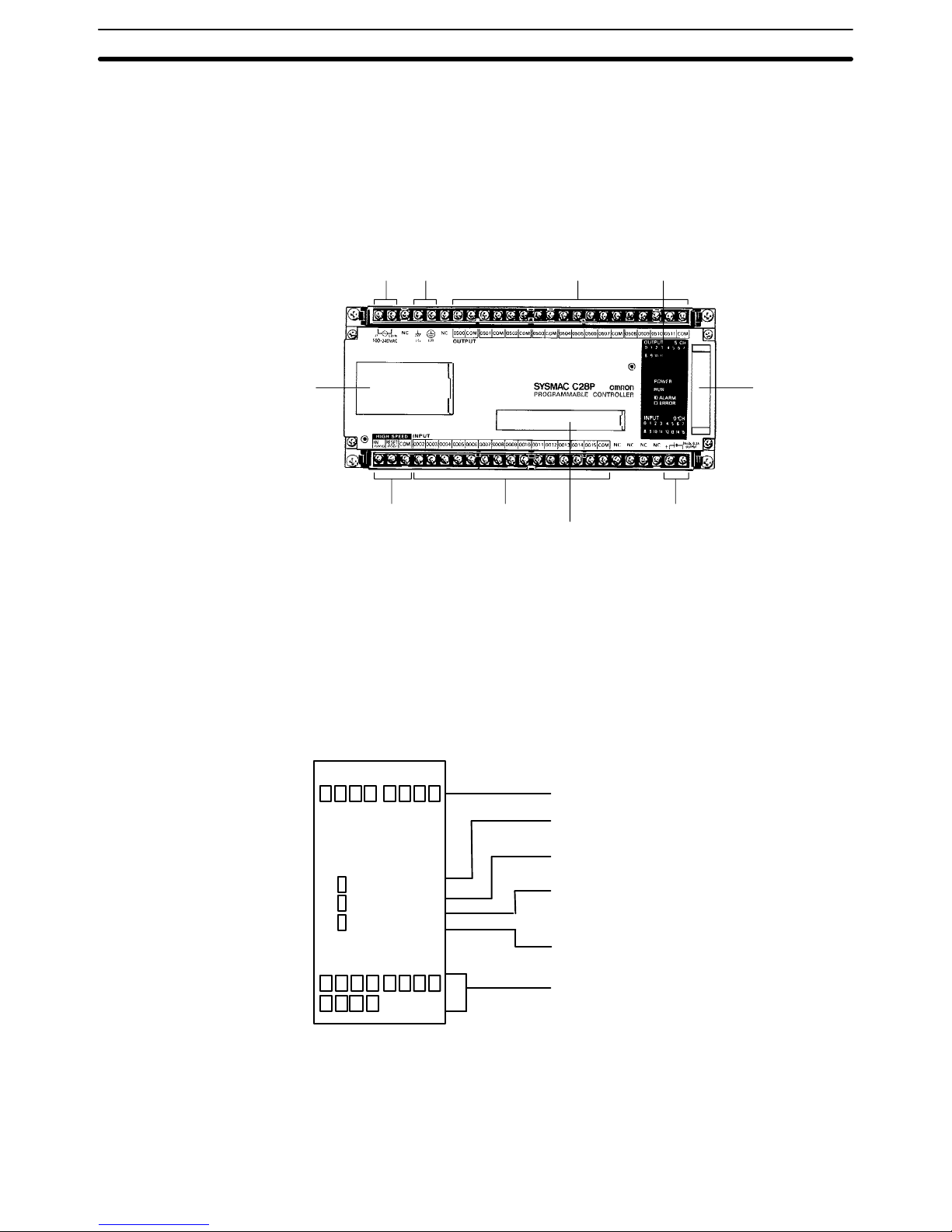
1-1-1 CPUs
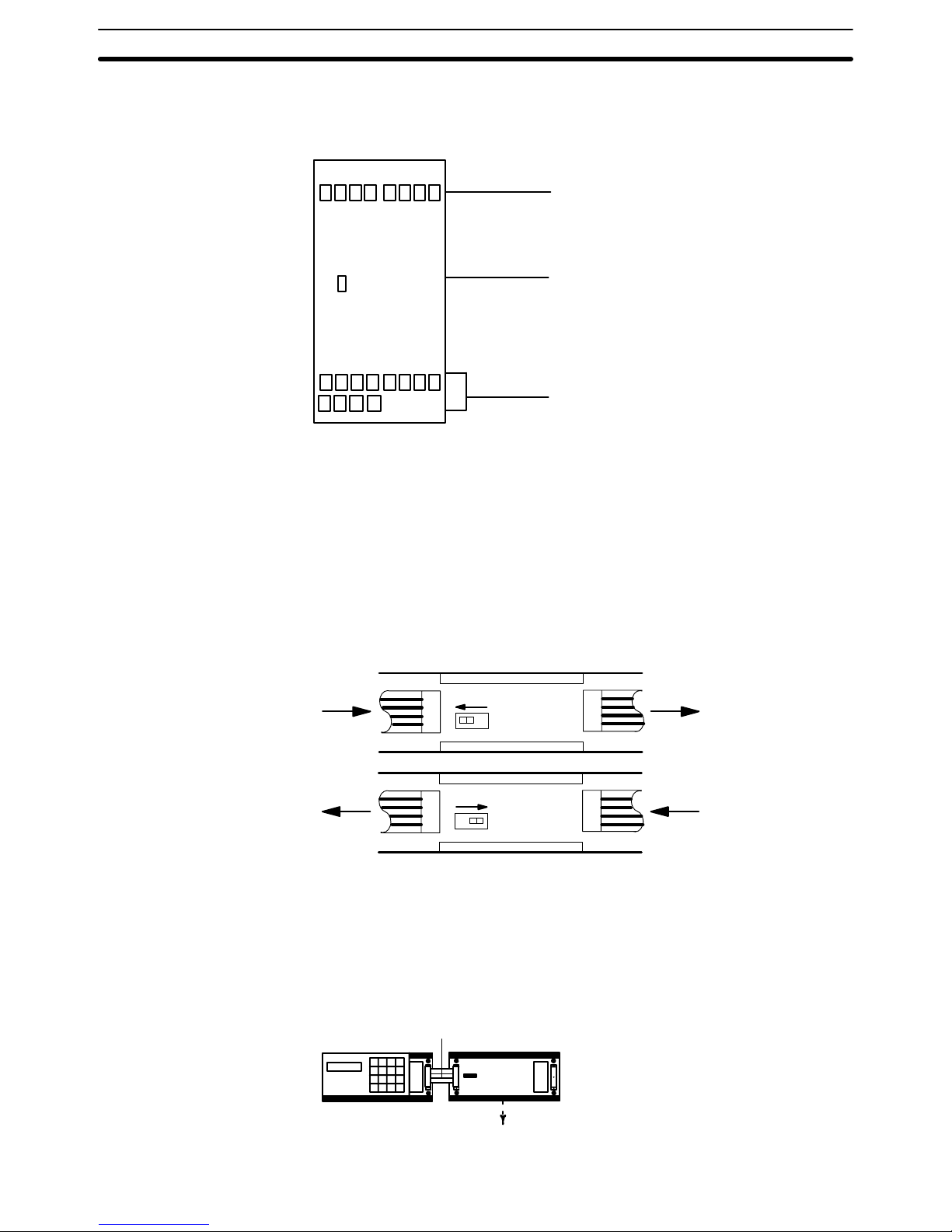
In the diagram below, the C28P is shown as a representative model. Refer to
Appendix A Standard Models for your model’s exact specifications.
Power supply Ground Outputs Indicators
CPU,
Expansion I/O
Unit, Analog
Timer Unit,
Analog I/O
Unit, or I/O
Link Unit
connector
24-VDC output
Peripheral connector
InputsHigh-speed counter
(HDM(98)
–) inputs
EPROM socket,
DIP switch
High-speed Counter When the high-speed counter (HDM(98)) is not being used, the two
high-speed counter input terminals can be used as normal DC input terminals. Their ON/OFF response time, however, will be shorter (0.15 ms max.).
Regardless of whether or not the high-speed counter command is being
used, DIP switch pins 7 and 8 must be off whenever the hardware reset is
not being used.
Indicators The diagram below shows the functions of the various indicators, taking the
C20P as an example.
8 9 10 11
0 1 2 3 4 5 6 7
OUTPUT 5 CH
POWER
RUN
ALARM
ERROR
INPUT 0 CH
OUTPUT: Shows whether the output is ON or OFF.
POWER: Stays lit while power is turned on to the
PC.
RUN: Stays lit while the PC is operating normally.
ALARM: Blinks during battery abnormality or scan
time overrun. At this time PC operation will be
intermittent.
ERROR: Lights when self-diagnosis detects an
abnormality. The PC will stop operating.
INPUT: Shows whether the input is ON or OFF.
0 1 2 3 4 5 6 7
Memory Each of the C-series P-type PCs is provided with a built-in RAM (random-ac-
cess memory), as well as a ROM (read-only memory) chip socket. Either
may be used with ease. It is recommended to use the RAM for programming
and, when the program is completed, to save it in a ROM chip for protection.
The memory capacity in either case is 1,194 addresses.
Nomenclature Section 1-1
3
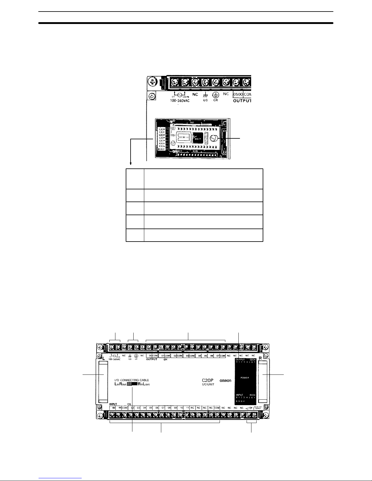
Beneath the cover are the DIP switch and the socket where an EPROM chip
may be installed. For details, see 2-8-1 Setting the CPU DIP Switch and
2-8-2 EPROM Installation. Only DIP switch pins 1 and 2 are on when the
CPU is delivered.
ROM socket
8 Turn ON to use hardware reset (0001).
7 Turn OFF if FUN 61 is not used.
6 Turn ON for English display.
5 Turn ON to inhibit ALARM indicator.
4, 3 ROM: ON (RAM: OFF)
2, 1 RAM: ON (ROM: OFF)
CAUTION: In case of battery failure, data stored in
the RAM, the DM area, the HR area, etc., will not be preserved.
1-1-2 Expansion I/O Units
In the diagram below, the C20P is shown as a representative model. Refer to
Appendix A Standard Models for your model’s exact specifications.
Power supply Ground Outputs Indicators
CPU,
Expansion
I/O Unit,
Analog Timer
Unit, Analog
I/O Unit, or
I/O Link Unit
connector
24-VDC outputInputsCPU left/right
selector
CPU,
Expansion
I/O Unit, or
I/O Link Unit
connector
ROM Socket and DIP
Switch
Nomenclature Section 1-1
4
Indicators The following diagram shows the functions of the various indicators, taking
the C20P as an example.
8 9 10 11
0 1 2 3 4 5 6 7
OUTPUT 5 CH
POWER
INPUT 0 CH
OUTPUT: Shows whether the output is ON or OFF.
POWER: Stays lit while power is turned ON to the
I/O Unit.
INPUT: Shows whether the input ON or OFF.
0 1 2 3 4 5 6 7
CPU Left/Right Selector The C20P, C28P, C40P, and C60P Expansion I/O Units all have CPU left/
right selector switches. The C16P and C4K do not. For those models which
have the switch, care must be taken to set it so that it corresponds with the
direction of the I/O Connecting Cable. If the switch is set in the wrong direction, the System will operate as if the I/O Unit were not there. Set the switch
so that the CPU connector side (Left or Right) is “in,” as shown in the following diagram. Do not change the switch setting after power has been turned
ON, as this will cause the I/O bus to malfunction.
Lin Rout
To I/O
Link
Unit
From
CPU
LR
Rin Lout
To I/O
Link
Unit
From
CPU
LR
The following example diagrams show the proper switch settings for horizontal and vertical mounting of Units.
Horizontal Mounting All Units can be positioned horizontally.
Set to Left in Right out
C20P-CN501
CPU
I/O Unit
Nomenclature Section 1-1
5
Vertical Mounting All Units except the C16P and C4K can be positioned vertically.
C20P-CN411
Set to Right in Left out
CPU
I/O Unit
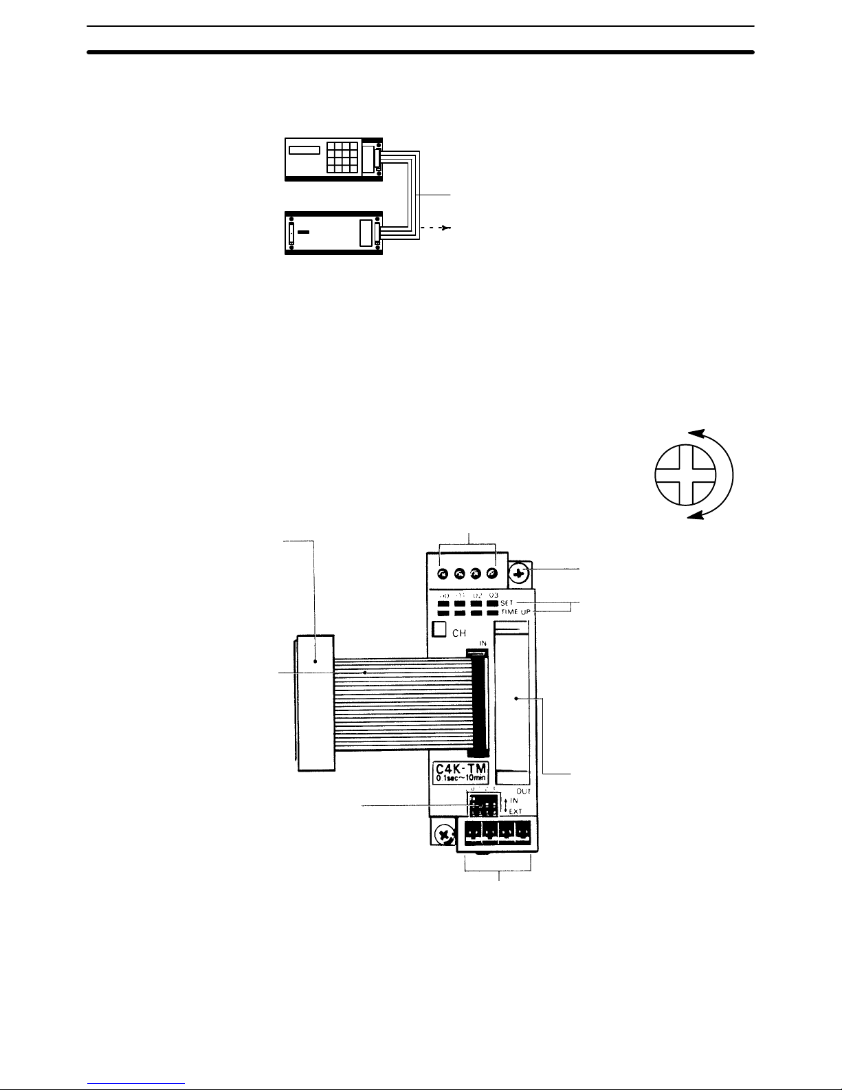
1-1-3 Analog Timer Unit
Internal variable resistors
These variable resistors are used to set the timers
and, from left to right, correspond to T0 to T3. The
settings of these resistors are effective only when the
corresponding IN/EXT selector is set to IN. To set or
adjust the time, use the screwdriver supplied with the
Analog Timer Unit. Turn the variable resistor shafts
clockwise to increase the time value.
Min.
Max.
Two M4 mounting screws
(self-rising pressure plate)
Indicators
The SET indicators in the top
row light while timer values
are being set. The TIME UP
indicators in the bottom row
light when the corresponding
timer contact (T0 to T3) turns
ON. Numbers 00 to 03 correspond to T0 to T3.
This connector is not used.
Do not remove the cover.
External variable resistor connectors
When using external variable resistors to set the timers, connect the
resistors to these connectors. The corresponding IN/EXT selector
must be set to the EXT position. These connectors correspond to
T0 to T3 from left to right. Use 20 kW external variable resistors. A
Connecting Cable with a 2-m lead is available for a variable resistor
(C4K-CN223).
CPU connector
Install and connect the Expansion
I/O Unit and the CPU horizontally;
otherwise the Analog Timer Unit
cannot be connected to the CPU.
I/O Connecting Cable
C4K-CN502
One cable is supplied with the
Analog Timer Unit
IN/EXT selectors
When using the internal variable
resistor, set the corresponding pin to
IN; when using an external variable
resistor, set the corresponding pin to
EXT. These selectors correspond to
T0 to T3 from left to right.
Nomenclature Section 1-1
6
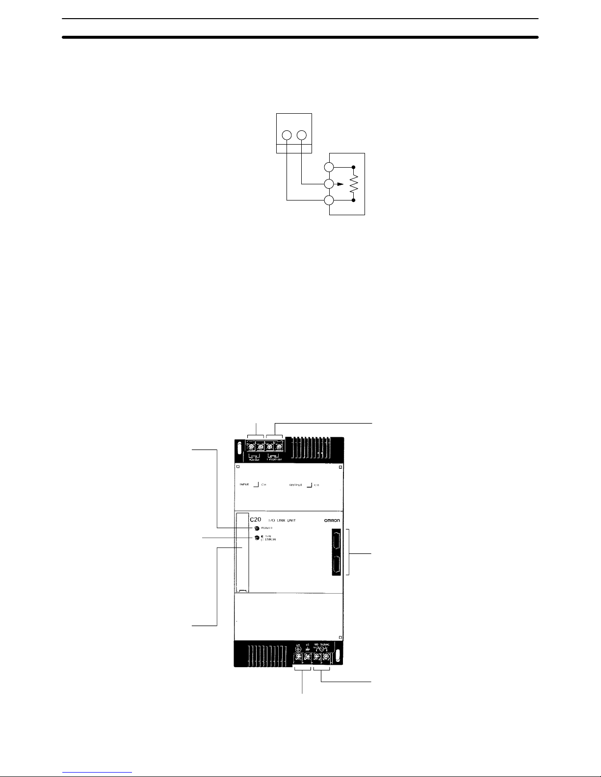
External Variable Resistor The contactor employs solderless terminals and must be wired as shown be-
low, using AWG 22 to 28 lead wires.
Analog Timer Unit
connector
External variable
resistor (20 kW)
1-1-4 I/O Link Units
The I/O Link Unit must be used as a Remote I/O Slave, and must be used
with a Remote I/O Master. Refer to the Remote I/O Unit Operation Guide for
details.
Operation output terminal
Indicates that the power is ON
and that the CPU is in RUN or
MONITOR mode with no errors.
Repeater Output Terminal
Sends repeater signals to a Link
Adapter. The repeater output is ON
when power is ON in the CPU and
I/O Link Unit. (See the Link Adapter
Manual for details.)
Optical fiber connectors
Transmitting error indicator
Blinks during normal transmission.
Lights continuously to indicate a
transmission or connection error.
AC power supply
Ground
CPU or Expansion
I/O Unit connector
Power indicator
Nomenclature Section 1-1
7
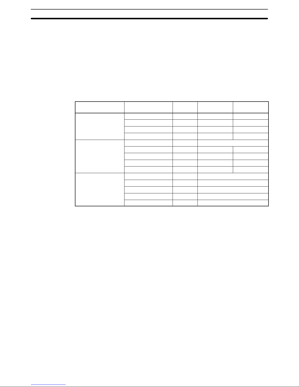
1-2 System Configuration
Depending on your control requirements, you can combine various Units for
a total number of I/O points ranging anywhere from 20 to 148.
A P-type PC consists of a CPU Unit plus one or more of the following Units:
Expansion I/O Units, Analog Timer Units, Analog I/O Units, or an I/O Link
Unit. All of these Units are connected in series with the CPU Unit at one end.
An I/O Link Unit, if included, must be on the other end (meaning only one I/O
Link Unit can be used) and an Analog Timer Unit cannot be used with. The
rest of the Units can be in any order desired. The Units from which P-type
PCs can be built are shown below.
Unit type Name Words
occupied
Inputs
provided
Outputs
provided
CPU C20P 2 12 points 8 points
C28P 2 16 points 12 points
C40P 4 24 points 16 points
C60P 4 32 points 24 points
Expansion I/O Unit C4K 2 4 input points or 4 output points
C20P 2 12 points 8 points
C28P 2 16 points 12 points
C40P 4 24 points 16 points
C60P 4 32 points 24 points
Special I/O Units Analog Timer Unit 2 4 timer inputs
C4K Analog Input Unit 2 4 analog inputs
C1K Analog Input Unit 2 1 analog input
Analog Output Unit 2 1 analog output
I/O Link Unit 2 16 input and 16 output bits
When determining which configuration to use, another factor to consider is
the ease with which I/O points can be assigned. In order to make the process
as simple as possible, it is recommended that a CPU be used which has
more I/O points than the largest Expansion I/O Unit. For example, rather than
combining a C20P CPU with a C20P Expansion I/O Unit, it would be preferable to use a C40P CPU. Similarly, combining a C60P CPU with a C40 Expansion I/O Unit would be better than using a C40P CPU and a C60P Expansion I/O Unit.
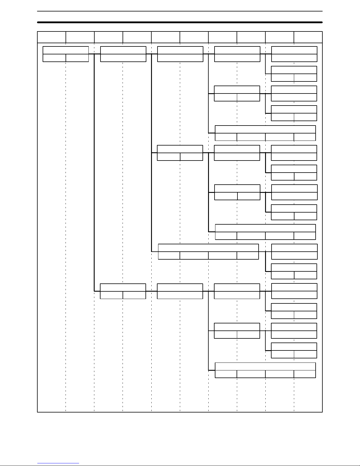
The tables on the following pages show the possible configurations for a
P-type PC. Although the tables branch to show the various possibilities at
any one point, there can be no branching in the actual PC connections. You
can choose either branch at any point and go as far as required, i.e., you can
break off at any point to create a smaller PC System.When implementing a
system there is a physical restriction on the total cable length allowable. The
sum of the lengths of all cables in the system must be limited to less than 1.2
meters.
The tables also show I/O word allocations for the Units in the systems and
which words will be input words and which words will be output words. All of
these are determined by the position of the Unit in the configuration except
for the C4P and C16P Expansion I/O Units, in which case the model of the
Unit determines whether the words are input or output.
System Configuration Section 1-2

8
The symbols used in the table represent the following:
C20P/C28P
Input Output
C20P/C28P/TU/AN/LU
Input Output
C4K/C16P
Input or Output
C40P/C60P
Input Output
Input Output
C20P or C28P CPU Unit
C40P or C60P CPU or
Expansion I/O Unit
C4K or C16P Expansion I/O Unit
C20P Expansion I/O Unit, C28P Expansion I/O Unit,
Analog Timer Unit, Analog I/O Unit, or I/O Link Unit
System Configuration Section 1-2
9
IR 00 IR 05 IR 01 IR 06 IR 02 IR 07 IR 03 IR 08 IR 04 IR 09
C20P/C28P
Input Output
C40P/C60P
Input Output Input Output
C20P/C28P/TU/AN/LU
Input Output
C20P/C28P/TU/AN/LU
Input Output
C20P/C28P/TU/AN/LU
Input Output
C20P/C28P/TU/AN/LU
Input Output
C20P/C28P/TU/AN/LU
Input Output
C20P/C28P/TU/AN/LU
Input Output
C20P/C28P/TU/AN/LU
Input Output
C40P/C60P
Input Output Input Output
C40P/C60P
Input Output Input Output
C20P/C28P/TU/AN/LU
Input Output
C20P/C28P/TU/AN/LU
Input Output
C20P/C28P/TU/AN/LU
Input Output
C20P/C28P/TU/AN/LU
Input Output
C20P/C28P/TU/AN/LU
Input Output
C40P/C60P
Input Output Input Output
C4K/C16P
Input or Output
C4K/C16P
Input or Output
C4K/C16P
Input or Output
C4K/C16P
Input or Output
C4K/C16P
Input or Output
C4K/C16P
Input or Output
C4K/C16P
Input or Output
C4K/C16P
Input or Output
C4K/C16P
Input or Output
C4K/C16P
Input or Output
C4K/C16P
Input or Output
C4K/C16P
Input or Output
C4K/C16P
Input or Output
System Configuration Section 1-2
10
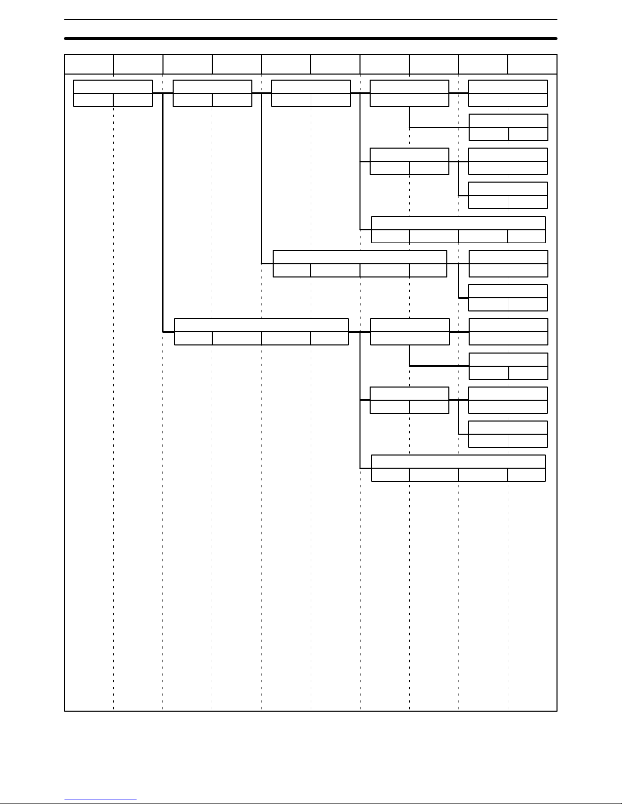
IR 00 IR 05 IR 01 IR 06 IR 02 IR 07 IR 03 IR 08 IR 04 IR 09
C20P/C28P
Input Output
C40P/C60P
Input Output Input Output
C20P/C28P/TU/AN/LU
Input Output
C20P/C28P/TU/AN/LU
Input Output
C20P/C28P/TU/AN/LU
Input Output
C20P/C28P/TU/AN/LU
Input Output
C20P/C28P/TU/AN/LU
Input Output
C40P/C60P
Input Output Input Output
C40P/C60P
Input Output Input Output
C40P/C60P
Input Output Input Output
C20P/C28P/TU/AN/LU
Input Output
C20P/C28P/TU/AN/LU
Input Output
C20P/C28P/TU/AN/LU
Input Output
C20P/C28P/TU/AN/LU
Input Output
C4K/C16P
Input or Output
C4K/C16P
Input or Output
C4K/C16P
Input or Output
C4K/C16P
Input or Output
C4K/C16P
Input or Output
C4K/C16P
Input or Output
C4K/C16P
Input or Output
System Configuration Section 1-2
11
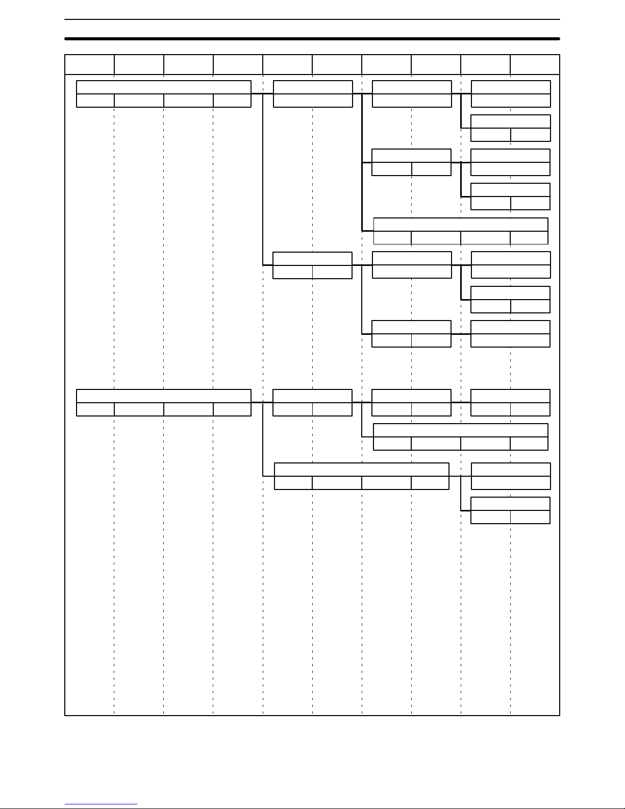
IR 00 IR 05 IR 01 IR 06 IR 02 IR 07 IR 03 IR 08 IR 04 IR 09
C40P/C60P
Input Output Input Output
C20P/C28P/TU/AN/LU
Input Output
C20P/C28P/TU/AN/LU
Input Output
C20P/C28P/TU/AN/LU
Input Output
C20P/C28P/TU/AN/LU
Input Output
C20P/C28P/TU/AN/LU
Input Output
C20P/C28P/TU/AN/LU
Input Output
C40P/C60P
Input Output
Input Output
C40P/C60P
Input Output
Input Output
C20P/C28P/TU/AN/LU
Input Output
C40P/C60P
Input Output Input Output
C20P/C28P/TU/AN/LU
Input Output
C20P/C28P/TU/AN/LU
Input Output
C40P/C60P
Input Output Input Output
C20P/C28P/TU/AN/LU
Input Output
C4K/C16P
Input or Output
C4K/C16P
Input or Output
C4K/C16P
Input or Output
C4K/C16P
Input or Output
C4K/C16P
Input or Output
C4K/C16P
Input or Output
C4K/C16P
Input or Output
C4K/C16P
Input or Output
System Configuration Section 1-2

13
SECTION 2
System Installation and Wiring
2-1 General 14. . . . . . . . . . . . . . . . . . . . . . . . . . . . . . . . . . . . . . . . . . . . . . . . . . . . . . . . . . . . . . . . .
2-2 Installation Environment 14. . . . . . . . . . . . . . . . . . . . . . . . . . . . . . . . . . . . . . . . . . . . . . . . . . .
2-3 Dimensions and Installation 16. . . . . . . . . . . . . . . . . . . . . . . . . . . . . . . . . . . . . . . . . . . . . . . . .
2-4 I/O Connecting Cable 21. . . . . . . . . . . . . . . . . . . . . . . . . . . . . . . . . . . . . . . . . . . . . . . . . . . . . .
2-5 Wiring CPUs and Expansion I/O Units 24. . . . . . . . . . . . . . . . . . . . . . . . . . . . . . . . . . . . . . . .
2-6 I/O Wiring 27. . . . . . . . . . . . . . . . . . . . . . . . . . . . . . . . . . . . . . . . . . . . . . . . . . . . . . . . . . . . . .
2-6-1 Unit Wiring Diagrams 27. . . . . . . . . . . . . . . . . . . . . . . . . . . . . . . . . . . . . . . . . . . . . .
2-6-2 I/O Device Connection Examples 43. . . . . . . . . . . . . . . . . . . . . . . . . . . . . . . . . . . . .
2-7 Special Wiring Precautions 44. . . . . . . . . . . . . . . . . . . . . . . . . . . . . . . . . . . . . . . . . . . . . . . . .
2-8 Switch Settings 46. . . . . . . . . . . . . . . . . . . . . . . . . . . . . . . . . . . . . . . . . . . . . . . . . . . . . . . . . . .
2-8-1 Setting the CPU DIP Switch 46. . . . . . . . . . . . . . . . . . . . . . . . . . . . . . . . . . . . . . . . .
2-8-2 EPROM Installation 47. . . . . . . . . . . . . . . . . . . . . . . . . . . . . . . . . . . . . . . . . . . . . . . .
2-8-3 High-speed Counter 48. . . . . . . . . . . . . . . . . . . . . . . . . . . . . . . . . . . . . . . . . . . . . . . .
2-8-4 Inhibiting the ALARM Indicator 48. . . . . . . . . . . . . . . . . . . . . . . . . . . . . . . . . . . . . .
2-8-5 Setting the I/O Link Unit 48. . . . . . . . . . . . . . . . . . . . . . . . . . . . . . . . . . . . . . . . . . . .
14
2-1 General
This section explains how to install and set up your Control System, with specifics on the proper environment, actual mounting, applicable cable, wiring,
and switch settings.
2-2 Installation Environment
Although the P-type Programmable Controller is quite durable, the following
conditions must be observed in order for your System to operate at its highest level of reliability.
Ambient temperature Operating: 0° to 55°C*
Storage: –20° to 65
°C
Humidity 35% to 45% (without condensation)
Must be free from the following:
• Corrosive gases
• Abrupt temperature changes
• Direct sunlight
Atmosphere
• Concentration of dust, salt, iron particles
• Splatter from water, oil, other chemicals
Vibration and shock Must not receive direct impact or vibration
*The ambient operating temperature for the Programming Console is 0° to 45°.
Caution In low humidity conditions, excessive static electricity of over 8 kV can dam-
age internal components such as ICs. Before touching the PC, be sure to
first touch a grounded metallic object to discharge any static electricity buildup.
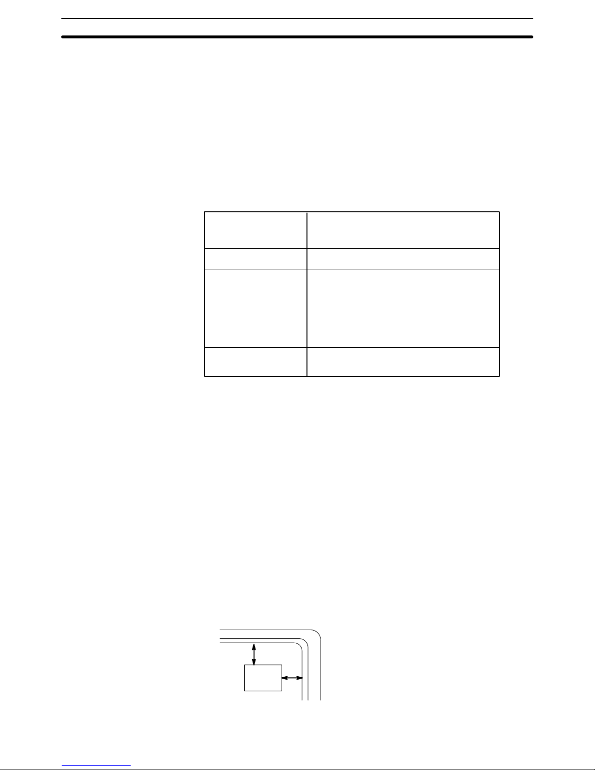
Noise Prevention Use twisted-pair cables with cross-sectional areas of at least 2 mm
2
/conductor (AGW 14) to prevent noise. Avoid mounting the PC close to high-power
equipment, and be sure to mount it at least 200 mm away from power lines.
Wherever possible, use wiring ducts to contain and protect the PC wiring.
The I/O wiring should not be placed in the same duct with the power line or
other wiring. Standard wiring conduits are sufficient as long as the I/O wiring
and power lines are kept separate.
200 mm
min.
200 mm min.
PC
Installation Environment Section 2-2
15
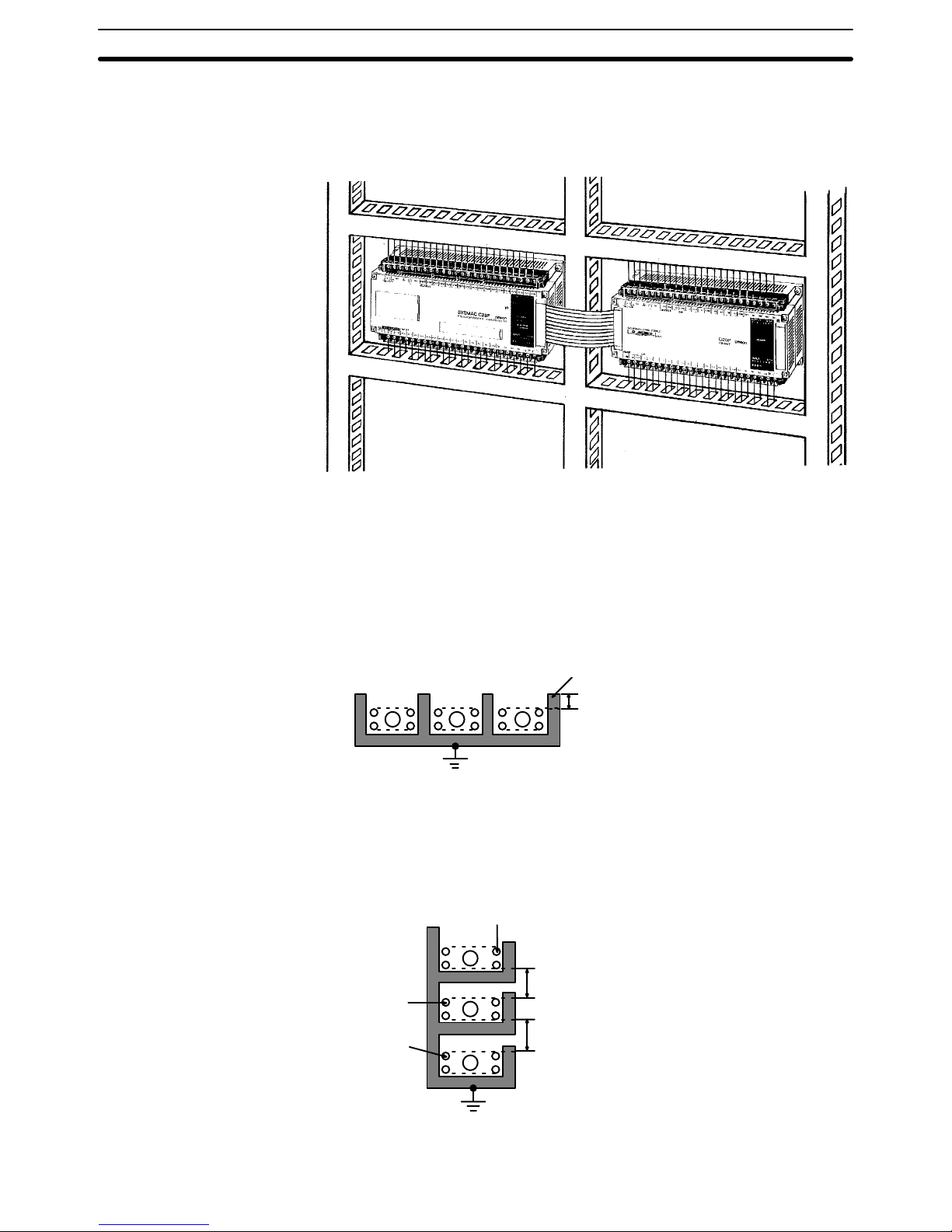
Duct Work When CPUs and Expansion I/O Units are mounted horizontally, be sure that
no ducts or wiring passes between them. The diagram shows an example of
unacceptable mounting.
If the controlled system requires either 10 A at 400 V max. or 20 A at 220 V
max. power cables, and if the conduits are run parallel to each other, a minimum distance of 300 mm must be provided between the I/O lines and the
power cable. If the I/O lines and the power cables must be placed in the
same duct at the point of connection to the equipment, be sure to screen
them with a grounded metal plate.
3
Metal (iron) plate
200 mm min.
Grounding (at a ground resistance of less than 100
W )
1 PC I/O circuit
2 PC power circuit
3 General control circuit/Power circuit
1
2
Weak current cable
300 mm min.
300 mm min.
Control cable
Power cable
Ground (at a resistance of
less than 100
W)
1
2
3
Installation Environment Section 2-2
16
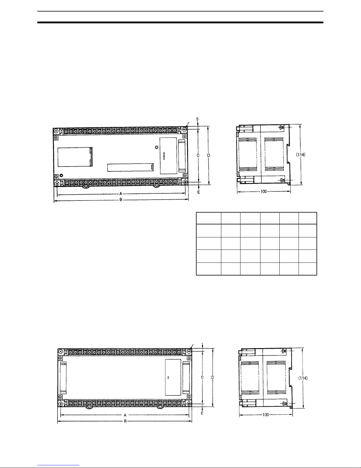
2-3 Dimensions and Installation
This section gives dimensions and other information necessary for mounting
the CPUs, Expansion I/O Units, Analog Timer Units, and I/O Link Units. All
measurements are in mm.
CPUs The C20P is shown below. Dimensions for all Units are given in the table.
A
240
240
290
340
Model
C20P
C28P
C40P
C60P
B
250
250
300
350
C
100
100
100
120
Four M4 screws
D
110
110
110
140
E
5
5
5
15
Expansion I/O Units The C20P is shown below. Dimensions for all Units are given in the table.
Four M4 screws
Dimensions and Installation Section 2-3
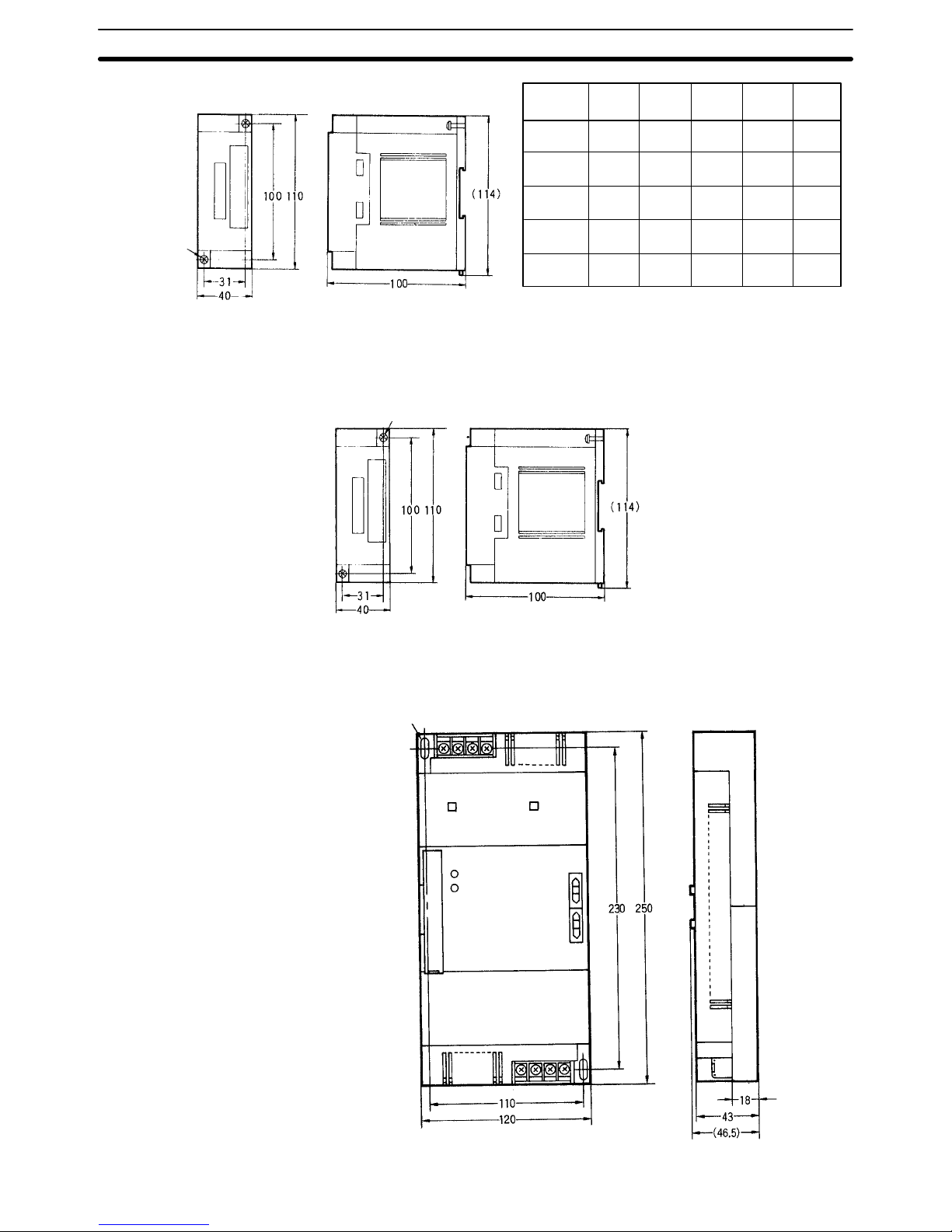
17
Model
C16P
C20P
C28P
C40P
C60P
A
145
240
240
290
340
B
155
250
250
300
350
C
100
100
100
100
120
D
110
110
110
110
140
E
5
5
5
5
15
C4K
Two, M4
Analog Timer Units C4K-TM
Two, M4
I/O Link Units C20-LK011(-P)
Two M4 holes
Dimensions and Installation Section 2-3
18
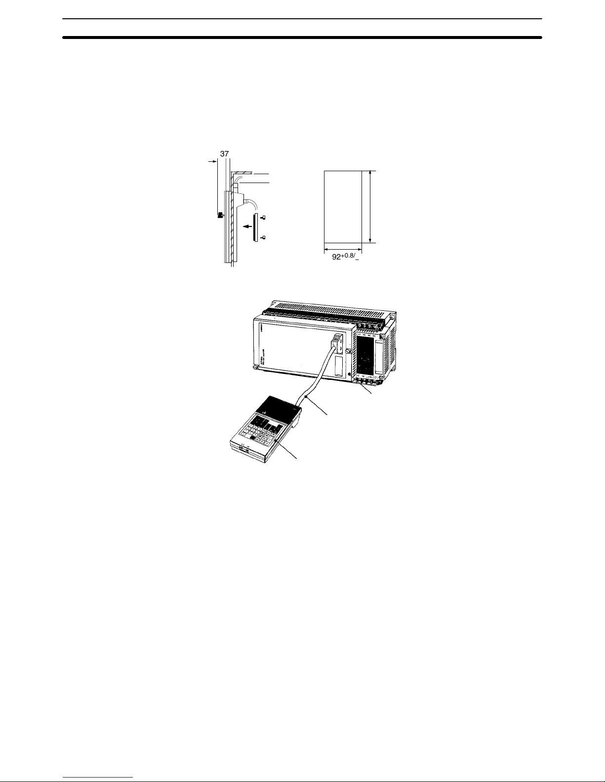
Programming Console The Hand-held Programming Console can be mounted to a panel if desired.
To do so, the Programming Console Mounting Bracket (C200H-ATT01, sold
separately) is required. Mounting dimensions and connections are shown
below. Only one connector should be used at any one time. When connecting the Programming Console, press in firmly until you hear it click into place.
C200H-PRO27-E
Panel Mounting
Approx. 80
Panel Cutout
(DIN 43700)
37
92
+0.8/
–0.0
186
+1.1
/
–0.0
P-type PC
Programming Console
Adapter 3G2A5-AP003
Programming Console Connecting Cable
C200H-CN222 (2 m) or C200H-CN422 (4 m)
Hand-held Programming Console
C200H-PRO27-E
The other Programming Consoles are normally connected directly to the
CPU and held in place with two mounting screw.
Caution Never run a Programming Console Connecting Cable past high-power lines
or other sources of electrical noise, as these will prevent correct operation.
Also, never leave the PC operating in RUN mode when the Programming
Console is connected via Connecting Cable, as noise entering through the
cable could also cause malfunctions in operation.
Note 1. Always keep the unused connector covered.
2. Do not attach a key holder to the switch key; it will interfere with operation.
3. The key cannot be removed in PROGRAM mode.
4. Use the switch on the upper right side of the Programming Console to
adjust the volume of the beeper.
5. The 3G2C6-CN122 (1 m) and 3G2C7-CN5111 (50 cm) Connecting
Cables are available to connect the 3G2A5-PRO13-E and
3G2A6-PRO15-E Programming Consoles. The Programming Console
Adapter is not required for these.
6. For operational information, refer to your PC’s Operation Manual.
Dimensions and Installation Section 2-3
19
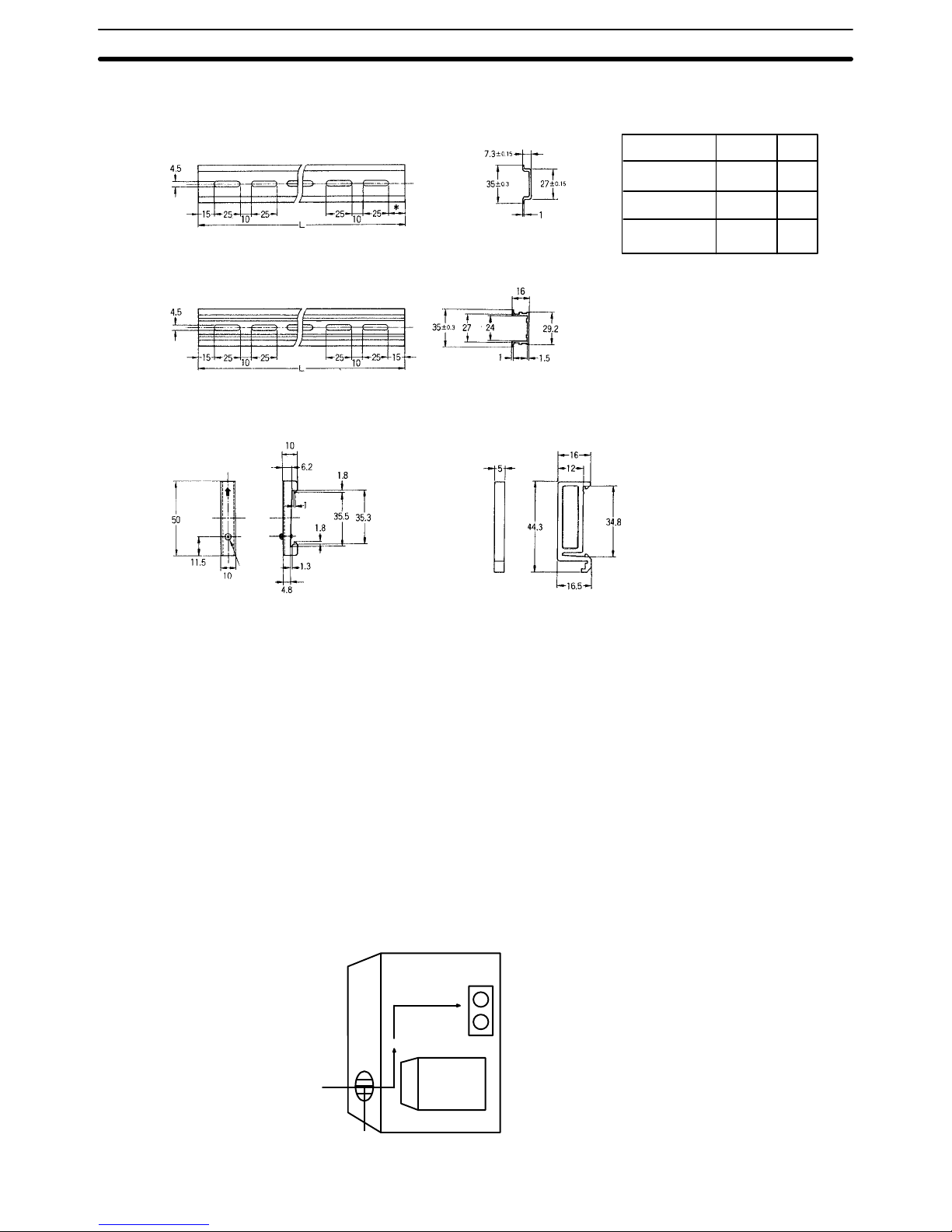
DIN Rails
*
5
15
––
Model
PFP-50N
PFP-100N
PFP-100N2
L
50 cm
1 m
1 m
Use the PFP-100N2 for the C60P.
If the PFP-50N or PFP-100N are
used, the Unit will be slanted.
PFP-50N/PFP-100N
PFP-100N2
Endplate PFP-M
Eight M4
panhead
screws
Spacer PFP-S
Mounting A CPU and Expansion I/O Unit may be mounted either vertically or horizon-
tally in relation to each other but the orientation of each unit itself must remain horizontal as described by the following mounting diagrams. If mounting
the units vertically, position the CPU above the Expansion I/O Unit; if mounting horizontally, position the CPU to the left.
When installing the CPUs, Expansion I/O Units, and I/O Link Units, allow sufficient space between the Units for cooling. Models taking a 100 to 240-VAC
power supply require a minimum cooling space of 10 mm between Units.
Avoid mounting any units in warm areas or over a heat source of any kind.In
addition, if the CPU is installed in a control box, allow sufficient space for
maintenance and ventilation. It may be necessary to install a ventilation fan
in the control box to maintain the required ambient temperature as indicated
in Appendix B Specifications.
Control Box
Fan
PC
Vent
Dimensions and Installation Section 2-3
20
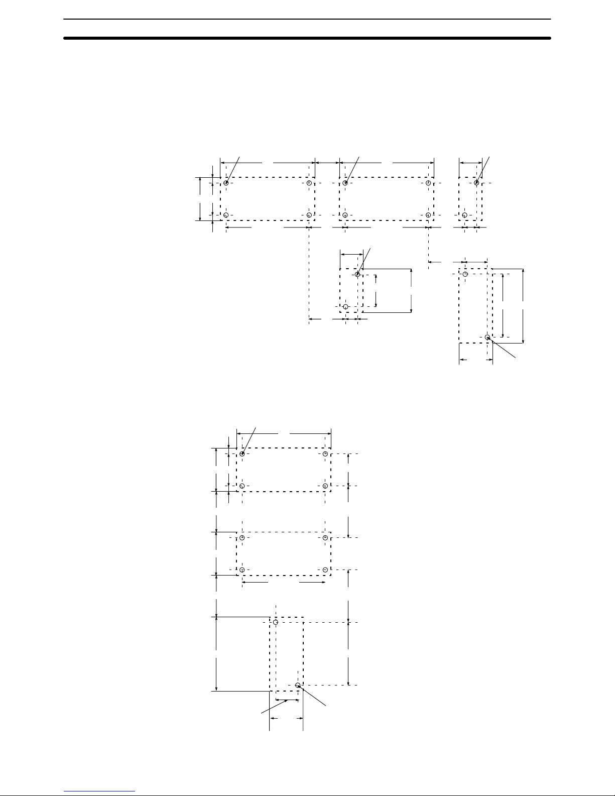
Another factor to consider is the I/O wiring (see 2-6 I/O Wiring). If the CPU
and/or Expansion I/O Units are mounted vertically, a minimum of 70 mm
open space is required for ease of I/O wiring. The spacing of the mounting
holes, for both vertical and horizontal mounting is as shown below.
Horizontal Mounting
A ± 0.2 A ± 0.2
G
A ± 0.2
D C
Four, M4 Four, M4 Two, M4
Expansion
I/O Unit
CPU
Analog
Timer Unit
B B
F–10
A ± 0.2
Two, M4
B
F
F
C ± 0.2
D
C4K
230 250
5
E
H
110
± 0.2
120
Two, M4
I/O
Link
Unit
Vertical Mounting
D C
Four, M4
CPU
B
5
A + 0.2
Expansion
I/O Unit
D
230
120
Two, M4
110 ± 0.2
230
I–10
I–10
C ± 0.2
I
I
I/O
Link
Unit
Dimensions and Installation Section 2-3
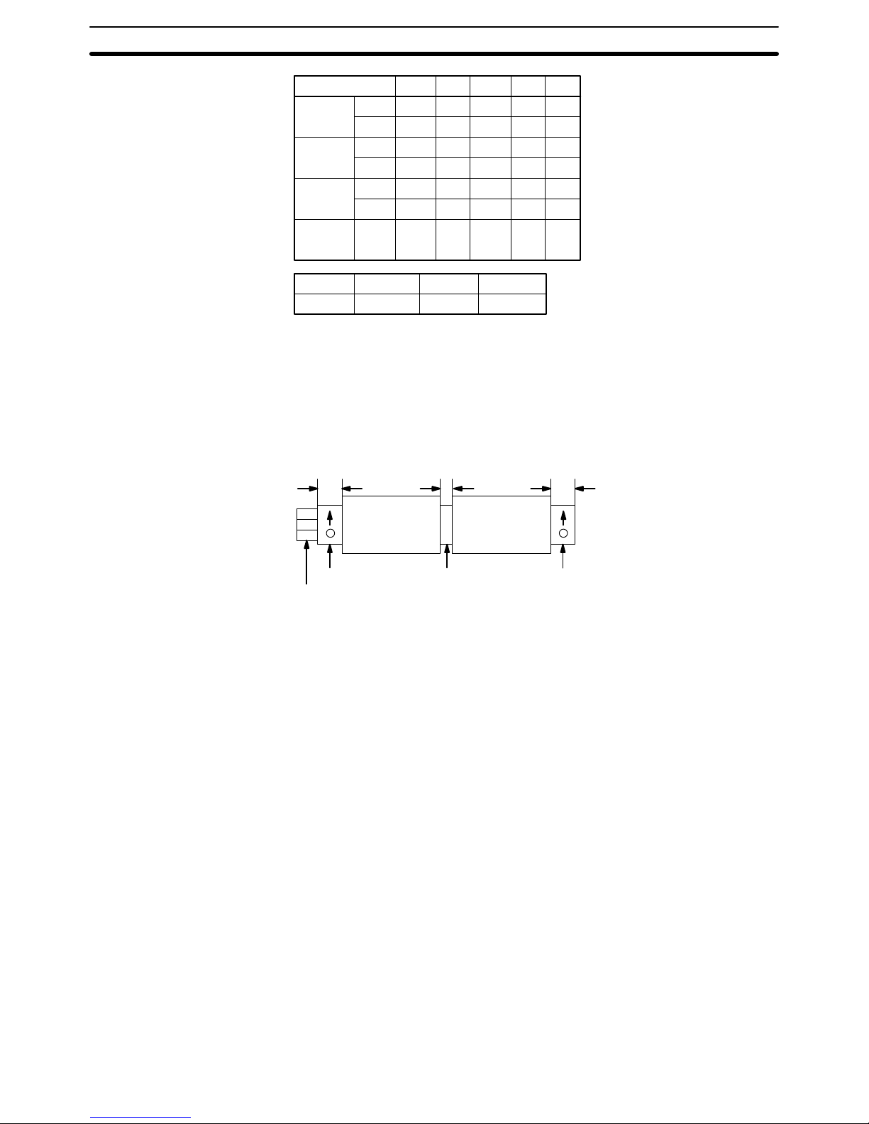
21
Model
CPU
I/O Unit
I/O Unit
Analog
Timer
Unit
C20P
C28P
C40P
C60P
C16P
C4K
C4K
-TM
A
±0.2
240
240
290
340
145
31
31
B
250
250
300
350
155
40
40
C
±0.2
100
100
100
120
100
100
100
D
110
110
110
140
110
110
110
E
5
5
5
15
5
5
5
F
15 to 40G15 to 35H20 to 40I80 to 130
Attach End Plates (PFP-M) to both ends (as shown below) when connecting
CPUs, Expansion I/O Units, or Analog Timer Units to a DIN Rail. It is also
recommended that a Spacer (PFP-S) be installed between a CPU and Expansion I/O Unit when they are mounted horizontally.
XX
510 10
End plate
DIN Rail
Spacer End plate
PC I/O Unit
Mounting screws are included with CPUs, Expansion I/O Units, and Analog
Timer Units. They must be purchased separately for I/O Link Units.
2-4 I/O Connecting Cable
Applicable connecting cable will vary according to which Units are connected
and whether they are mounted horizontally or vertically. All Expansion I/O
Units except the C16P and C4K use C20P-CN501 cable (5 cm) for horizontal
mounting and C20P-CN411 cable (40 cm) for vertical mounting. The C16P
and C4K cannot be mounted vertically. The C16P can use either of the
above-mentioned cables for horizontal mounting. The C4K can use only
C4K-CN502 cable (5 cm). For connecting I/O Link Units, use C20P-CN711
cable (70 cm).
Caution Always be sure to use only the cable that is included with the Unit. Using the
wrong cable (such as the C20 I/O Connecting Cable or I/O Link Connecting
Cable) for connecting Expansion I/O Units can cause serious damage to the
Units.
I/O Connecting Cable Section 2-4

22
The following diagrams illustrate the appropriate cables for connecting CPUs,
Expansion I/O Units, and I/O Link Units either horizontally or vertically.
5 to 30 cm
I/O Connecting
Cable C20P-CN501
100 to 200mm
100 to 200mm
Horizontal Mounting
CPU
I/O Unit
CPU
I/O Unit
I/O Unit
CPU
I/O Link Connecting
Cable C20P-CN711
I/O Link
Unit
I/O Link
Unit
I/O Link
Unit
Vertical Mounting
I/O Connecting
Cable C20P-CN411
I/O Link Connecting
Cable C20P-CN711
I/O Link Connecting
Cable C20-CN711
I/O Connecting
Cable C20P-CN411
One Analog Timer Unit can be connected directly to a CPU or to any combination of a CPU and Expansion I/O Units. In either case, as shown in the following diagram, the Units must be mounted horizontally.
Analog
Timer Unit
Connecting Cable
C4K-CN502
Analog
Timer Unit
Connecting Cable
C4K-CN502
CPU
CPU
I/O Unit
Connecting Analog Timer
Units
I/O Connecting Cable Section 2-4
23
Connecting I/O Link Units One I/O Link Unit can be connected directly to a CPU or to any combination
of a CPU and Expansion I/O Units. It cannot be used in the same PC System
with an Analog Timer Unit.
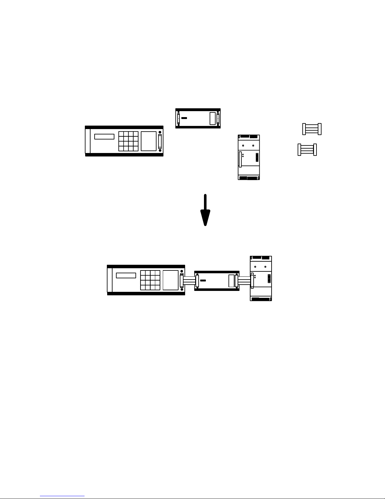
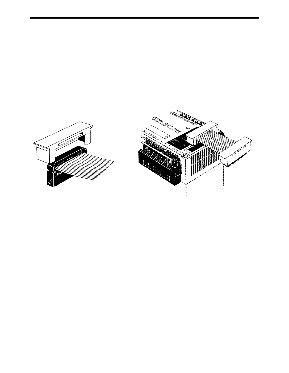
Connection Procedure Follow these four steps to connect Expansion I/O Unit, Analog Timer, and I/O
Link Unit Connecting Cables.
1, 2, 3... 1. Remove the connector cover from the CPU, using a screwdriver if nec-
essary.
2. Insert one of the cable’s connectors into the cover. (Once inserted, the
connector cannot be removed.)
3. Reinsert the cover/connector combination into the CPU.
4. Repeat this procedure on the other end of the cable.
Cover
Optical Fiber Cable Optical fiber cable can be used for extending transmission distance and re-
ducing noise. There are three types, and the appropriate cable for any given
situation will depend on the desired transmission distance and the particular
Units which need to be connected.
All-plastic optical fiber cable (APF) is for short-distance transmission (up to
20 m) and can be used only by Units with the suffix “-P” attached. Plastic-clad optical fiber cable (PCF) is for middle-distance transmission (up to
200 m for Units with “-P” and 800 m for Units without “-P”). Crystal optical
fiber cable (AGF) is for long-distance transmission (up to 3 km) and can be
connected only to certain Link Adapters.
Although laying optical fiber cable does not basically differ from laying wire
cable, there are certain precautions which should be observed. For details,
refer to the Optical Remote I/O Systems Manual.
Link Adapters Although it is normally possible to connect Units in series, a failure (power
failure, disconnection, etc.) in one of the Units will cause all the subsequent
Units to cease operating. You can use Link Adapters to prevent this type of
situation from occurring. Even if a power failure occurs in a Unit connected to
a branch line of a Link Adapter, the Link Adapter will bypass that Unit and
continue to transmit signals to the other Units. You can also use Link Adapters for branching and for converting between various types of wire and optical cable. For details on these and other functions of Link Adapters, refer to
the Link Adapter Manual.
I/O Connecting Cable Section 2-4
 Loading...