

Page 1
Cat. No. W147-E1-02B
Page 2
K-type Programmable Controllers
Installation Guide
Revised August 1993
C20P
C60K
C60K
C20P
Page 3

iv
Page 4

v
Notice:
OMRON products are manufactured for use according to proper procedures by a qualified operator
and only for the purposes described in this manual.
The following conventions are used to indicate and classify precautions in this manual. Always heed
the information provided with them. Failure to head precautions can result in injury to people or damage to the product.
DANGER! Indicates information that, if not heeded, is likely to result in loss of life or serious
injury.
WARNING Indicates information that, if not heeded, could possibly result in loss of life or
serious injury.
Caution Indicates information that, if not heeded, could result in relative serious or minor
injury, damage to the product, or faulty operation.
OMRON Product References
All OMRON products are capitalized in this manual. The word “Unit” is also capitalized when it refers
to an OMRON product, regardless of whether or not it appears in the proper name of the product.
The abbreviation “Ch,” which appears in some displays and on some OMRON products, means
“word” and is abbreviated “Wd” in documentation.
Visual Aids
The following headings appear in the left column of the manual to help you locate different types of
information.
Indicates information of particular interest for efficient and convenient operation of the product.
Indicates lists of one sort or another, such as procedures, precautions, etc.
OMRON, 1989
All rights reserved. No part of this publication may be reproduced, stored in a retrieval system, or transmitted, in any
form, or by any means, mechanical, electronic, photocopying, recording, or otherwise, without the prior written permission of OMRON.
No patent liability is assumed with respect to the use of the information contained herein. Moreover, because OMRON is
constantly striving to improve its high–quality products, the information contained in this manual is subject to change
without notice. Every precaution has been taken in the preparation of this manual. Nevertheless, OMRON assumes no
responsibility for errors or omissions. Neither is any liability assumed for damages resulting from the use of the information contained in this publication.
Note
1, 2, 3...
Page 5

vi
Page 6

vii
TABLE OF CONTENTS
SECTION 1
Introduction 1. . . . . . . . . . . . . . . . . . . . . . . . . . . . . . . . . . . . .
1–1 Nomenclature 2. . . . . . . . . . . . . . . . . . . . . . . . . . . . . . . . . . . . . . . . . . . . . . . . . . . . . . . . . . . .
1–2 System Configuration 7. . . . . . . . . . . . . . . . . . . . . . . . . . . . . . . . . . . . . . . . . . . . . . . . . . . . . .
SECTION 2
System Installation and Wiring 9. . . . . . . . . . . . . . . . . . . . .
2–1 General 10. . . . . . . . . . . . . . . . . . . . . . . . . . . . . . . . . . . . . . . . . . . . . . . . . . . . . . . . . . . . . . . . .
2–2 Installation Environment 10. . . . . . . . . . . . . . . . . . . . . . . . . . . . . . . . . . . . . . . . . . . . . . . . . . .
2–3 Dimensions and Installation 12. . . . . . . . . . . . . . . . . . . . . . . . . . . . . . . . . . . . . . . . . . . . . . . . .
2–4 I/O Connecting Cable 16. . . . . . . . . . . . . . . . . . . . . . . . . . . . . . . . . . . . . . . . . . . . . . . . . . . . . .
2–5 Wiring CPUs and Expansion I/O Units 19. . . . . . . . . . . . . . . . . . . . . . . . . . . . . . . . . . . . . . . .
2–6 I/O Wiring 22. . . . . . . . . . . . . . . . . . . . . . . . . . . . . . . . . . . . . . . . . . . . . . . . . . . . . . . . . . . . . .
2–7 Special Wiring Precautions 39. . . . . . . . . . . . . . . . . . . . . . . . . . . . . . . . . . . . . . . . . . . . . . . . .
2–8 Settings 41. . . . . . . . . . . . . . . . . . . . . . . . . . . . . . . . . . . . . . . . . . . . . . . . . . . . . . . . . . . . . . . . .
SECTION 3
Maintenance and Inspection 47. . . . . . . . . . . . . . . . . . . . . . .
3–1 General 48. . . . . . . . . . . . . . . . . . . . . . . . . . . . . . . . . . . . . . . . . . . . . . . . . . . . . . . . . . . . . . . . .
3–2 Self–Diagnostic Functions 48. . . . . . . . . . . . . . . . . . . . . . . . . . . . . . . . . . . . . . . . . . . . . . . . . .
3–3 Replacing Parts 49. . . . . . . . . . . . . . . . . . . . . . . . . . . . . . . . . . . . . . . . . . . . . . . . . . . . . . . . . . .
3–4 Preventive Measures 52. . . . . . . . . . . . . . . . . . . . . . . . . . . . . . . . . . . . . . . . . . . . . . . . . . . . . .
3–5 Inspection 54. . . . . . . . . . . . . . . . . . . . . . . . . . . . . . . . . . . . . . . . . . . . . . . . . . . . . . . . . . . . . . .
Appendices
A Standard Models 55. . . . . . . . . . . . . . . . . . . . . . . . . . . . . . . . . . . . . . . . . . . . . . . . . . . . . . . . . . . . .
B Specifications 63. . . . . . . . . . . . . . . . . . . . . . . . . . . . . . . . . . . . . . . . . . . . . . . . . . . . . . . . . . . . . . .
C Programming Console Operations 69. . . . . . . . . . . . . . . . . . . . . . . . . . . . . . . . . . . . . . . . . . . . . . .
D Programming Instructions 71. . . . . . . . . . . . . . . . . . . . . . . . . . . . . . . . . . . . . . . . . . . . . . . . . . . . .
E System Configuration Chart 77. . . . . . . . . . . . . . . . . . . . . . . . . . . . . . . . . . . . . . . . . . . . . . . . . . . .
Index 83. . . . . . . . . . . . . . . . . . . . . . . . . . . . . . . . . . . . . . . . . . .
Revision History 85. . . . . . . . . . . . . . . . . . . . . . . . . . . . . . . . .
Page 7

ix
About this Manual:
This manual has been prepared to provide the information necessary to install, set up, and maintain
your C-series K-type Programmable Controller, a low-cost, compact, versatile industrial control system providing up to 148 I/O points. For information regarding system programming and operation,
refer to the operation manual.
Refer to the Appendix for a complete list of all products covered in this manual, along with their full
model numbers.
Page 8

x
Page 9

1
SECTION 1
Introduction
1–1 Nomenclature 2. . . . . . . . . . . . . . . . . . . . . . . . . . . . . . . . . . . . . . . . . . . . . . . . . . . . . . . . . . . .
1–1–1 CPUs 2. . . . . . . . . . . . . . . . . . . . . . . . . . . . . . . . . . . . . . . . . . . . . . . . . . . . . . . . . . .
1–1–2 Expansion I/O Units 3. . . . . . . . . . . . . . . . . . . . . . . . . . . . . . . . . . . . . . . . . . . . . . . .
1–1–3 Analog Timer Unit 5. . . . . . . . . . . . . . . . . . . . . . . . . . . . . . . . . . . . . . . . . . . . . . . . .
1–1–4 I/O Link Units 6. . . . . . . . . . . . . . . . . . . . . . . . . . . . . . . . . . . . . . . . . . . . . . . . . . . .
1–2 System Configuration 7. . . . . . . . . . . . . . . . . . . . . . . . . . . . . . . . . . . . . . . . . . . . . . . . . . . . . .
Page 10
2
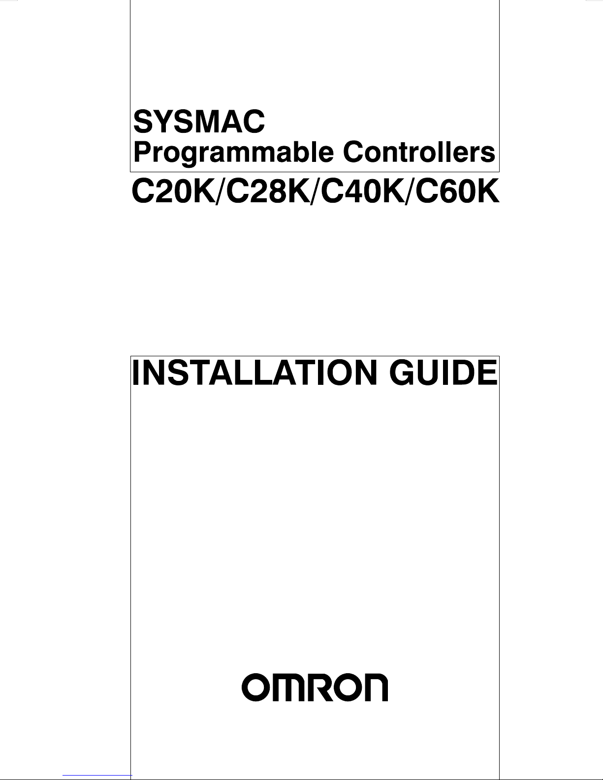
1–1 Nomenclature
This section gives the names and functions of the various components of
K–Type PCs and the basic Units with which they can be combined in a
System.
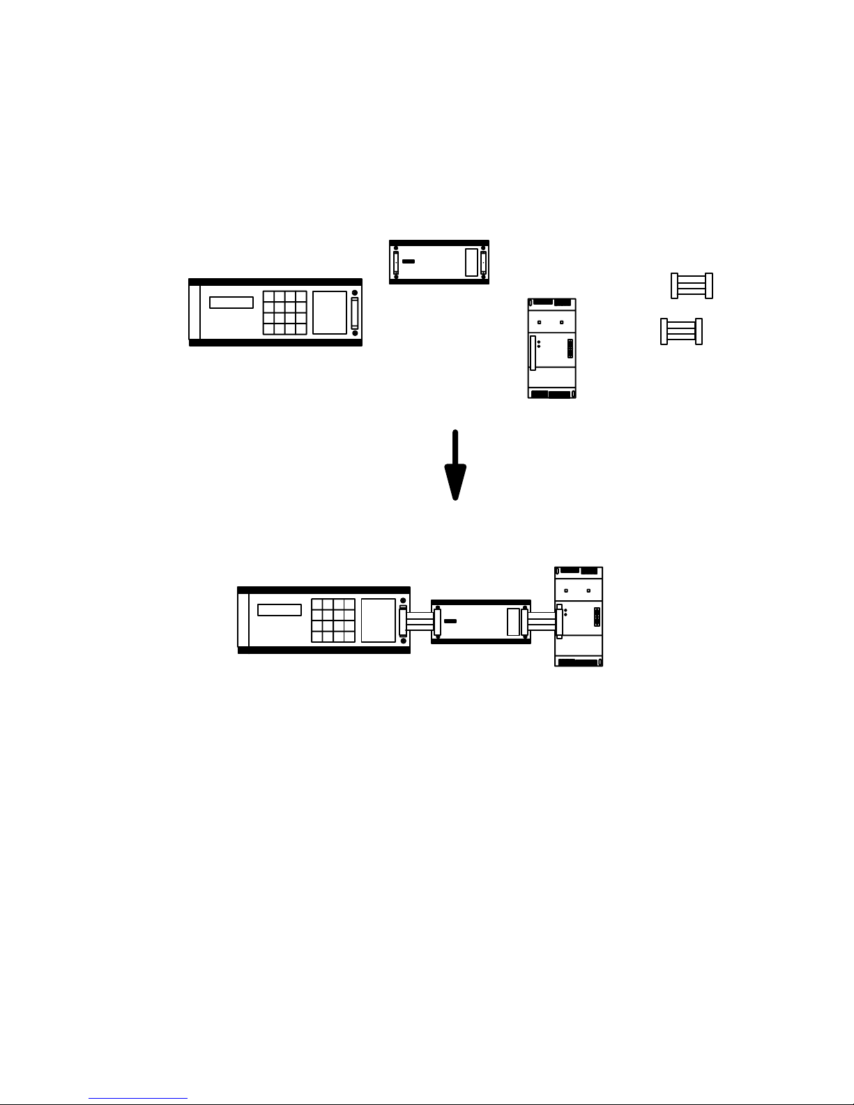
1–1–1 CPUs
In the diagram below, the C20K is shown as a representative model. Refer to
Appendix A Standard Models for your model’s exact specifications.
Power supply Ground Outputs Indicators
Expansion
I/O Unit,
Analog
Timer Unit, or
I/O Link Unit
connector
24–VDC output
Peripheral connector
InputsHigh–speed counter
(HDM) inputs
EP–ROM socket,
DIP switch
High–speed Counter When the high–speed counter (HDM(61)) is not being used, the two high–
speed counter input terminals can be used as normal DC input terminals.
Their ON/OFF response time, however, will be shorter (0.15 ms max.). Regardless of whether or not the high–speed counter command is being used,
DIP switch pins 7 and 8 must be off whenever the hardware reset is not being used.
Indicators The diagram below shows the functions of the various indicators, taking the
C20K as an example.
8 9 10 11
0 1 2 3 4 5 6 7
OUTPUT 1 CH
POWER
RUN
ALARM
ERROR
INPUT 0 CH
OUTPUT: Shows whether the output is ON or OFF.
POWER: Stays lit while power is turned on to the
PC.
RUN: Stays lit while the PC is operating normally.
ALARM: Blinks during battery abnormality or cycle
time overrun. At this time PC operation will be
intermittent.
ERROR: Lights when self–diagnosis detects an
abnormality. The PC will stop operating.
INPUT: Shows whether the input is ON or OFF.
0 1 2 3 4 5 6 7
Memory Each of the C–Series K–Type PCs is provided with a built–in RAM (random–
access memory), as well as a ROM (read–only memory) chip socket. Either
may be used with ease. It is recommended to use the RAM for programming
and, when the program is completed, to save it in a ROM chip for protection.
The memory capacity in either case is 1,194 addresses.
Nomenclature Section 1–1
Page 11
3
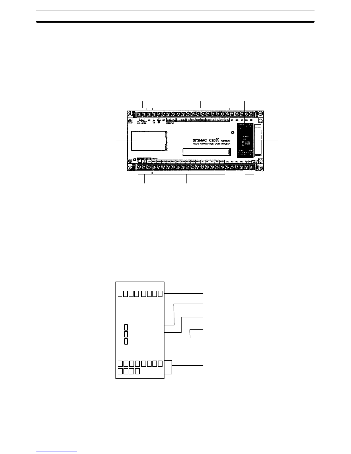
Beneath the cover are the DIP switch and the socket where an EP–ROM
chip may be installed. For details, see 2–7–1 Setting the CPU Dipswitch and
2–7–2 EP–ROM Installation. Only DIP switch pins 1 and 2 are on when the
CPU is delivered.
ROM socket
8 Turn ON to use hardware reset (0001).
7 Turn OFF if HDM(61) is not used.
6 Turn ON for English display.
5 Turn ON to inhibit ALARM indicator.
4, 3 ROM: ON (RAM: OFF)
2, 1 RAM: ON (ROM: OFF)
CAUTION: In case of battery failure, data stored in
the RAM, the DM area, the HR area, etc., will not be preserved.
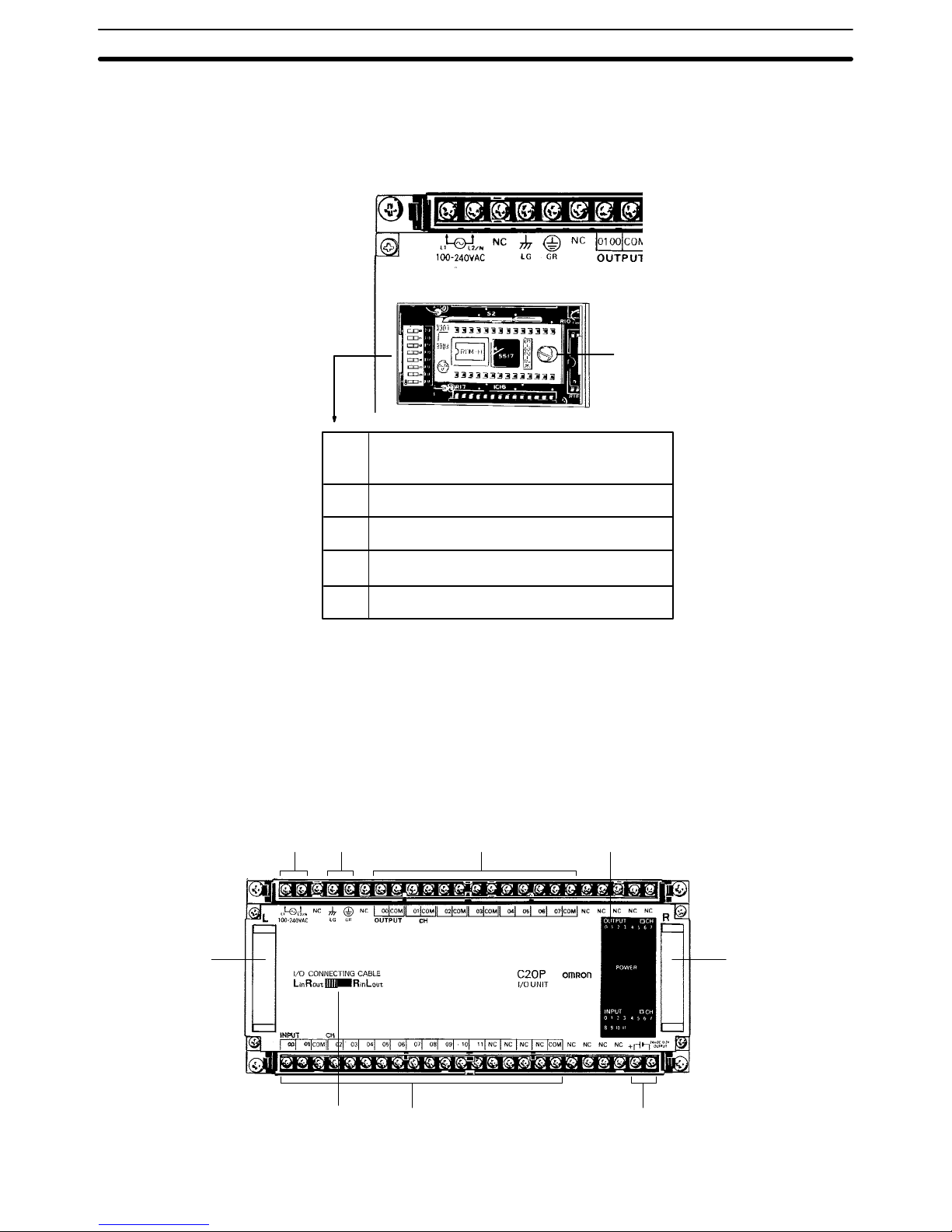
1–1–2 Expansion I/O Units
In the diagram below, the C20P is shown as a representative model. Refer to
Appendix A Standard Models for your model’s exact specifications.
Power supply Ground Outputs Indicators
CPU,
Expansion
I/O Unit,
Analog
Timer Unit, or
I/O Link Unit
connector
24–VDC outputInputsCPU left/right
selector
CPU,
Expansion
I/O Unit, or
I/O Link Unit
connector
ROM Socket and DIP
Switch
Nomenclature Section 1–1
Page 12
4
Indicators The following diagram shows the functions of the various indicators, taking
the C20P as an example.
8 9 10 11
0 1 2 3 4 5 6 7
OUTPUT 5 CH
POWER
INPUT 0 CH
OUTPUT: Shows whether the output is ON or OFF.
POWER: Stays lit while power is turned ON to the
I/O Unit.
INPUT: Shows whether the input ON or OFF.
0 1 2 3 4 5 6 7
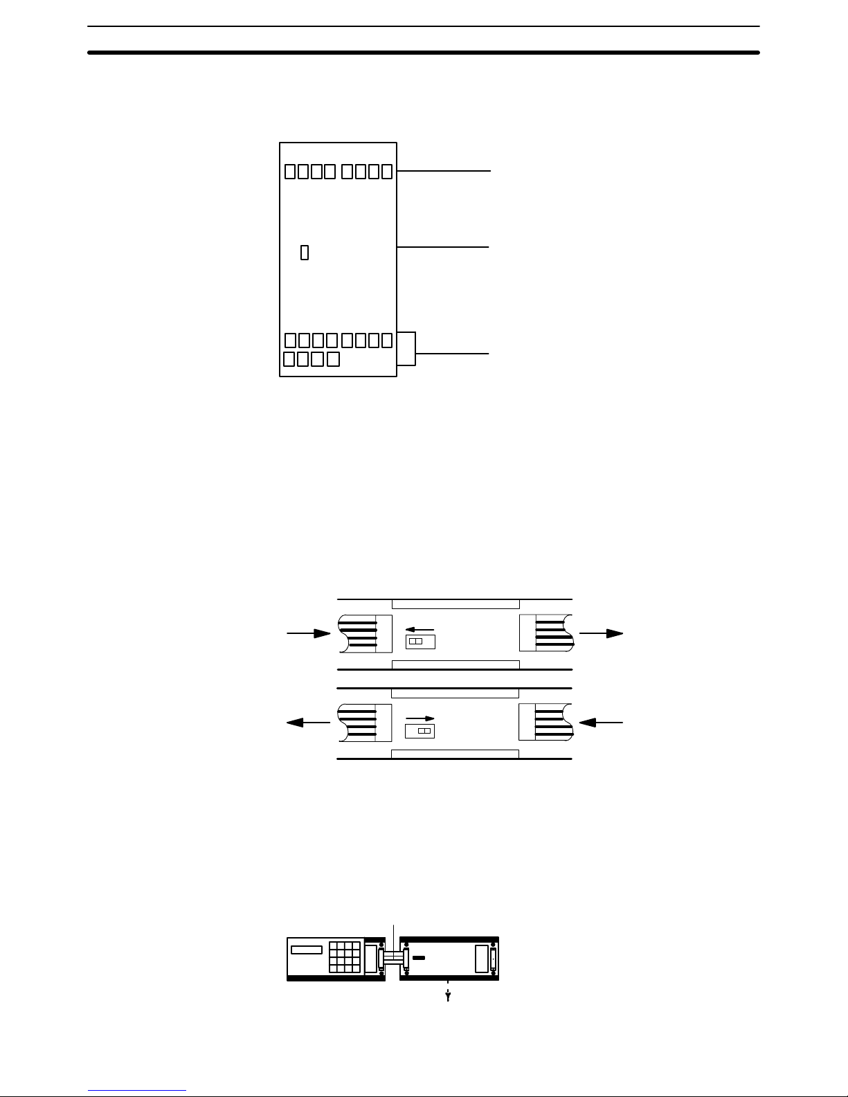
CPU Left/Right Selector The C20P, C28P, C40P, and C60P Expansion I/O Units all have CPU left/
right selector switches. The C16P and C4K do not. For those models which
have the switch, care must be taken to set it so that it corresponds with the
direction of the I/O Connecting Cable. If the switch is set in the wrong direction, the System will operate as if the I/O Unit were not there. Set the switch
so that the CPU connector side (Left or Right) is ”in,” as shown in the following diagram. Do not change the switch setting after power has been turned
ON, as this will cause the I/O bus to malfunction.
Lin Rout
To I/O
Link
Unit
From
CPU
LR
Rin Lout
To I/O
Link
Unit
From
CPU
LR
The following example diagrams show the proper switch settings for horizontal and vertical mounting of Units.
Horizontal Mounting (All Units can be positioned horizontally.)
Set to Left in Right out
C20P–CN501
CPU
I/O Unit
Nomenclature Section 1–1
Page 13
5
Vertical Mounting (All Units except the C16P and C4K can be positioned vertically.)
C20P–CN411
Set to Right in Left out
CPU
I/O Unit
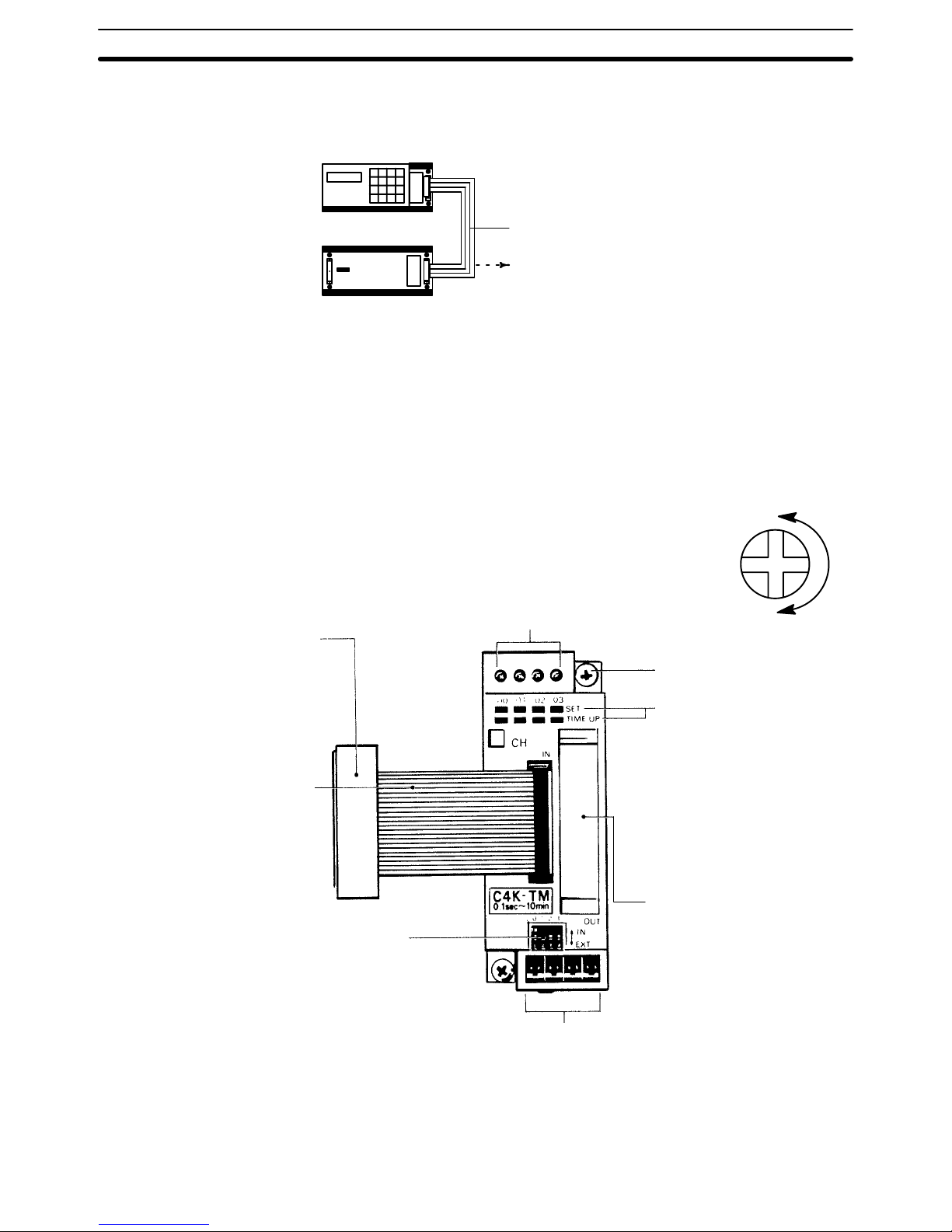
1–1–3 Analog Timer Unit
Internal variable resistors
These variable resistors are used to set the timers
and, from left to right, correspond to T0 to T3. The
settings of these resistors are effective only when the
corresponding IN/EXT selector is set to IN. To set or
adjust the time, use the screwdriver supplied with the
Analog Timer Unit. Turn the variable resistor shafts
clockwise to increase the time value.
Min.
Max.
Two M4 mounting screws
(self–rising pressure plate)
Indicators
The SET indicators in the top
row light while timer values
are being set. The TIME UP
indicators in the bottom row
light when the corresponding
timer contact (T0 to T3) turns
ON. Numbers 00 to 03 correspond to T0 to T3.
This connector is not used.
Do not remove the cover.
External variable resistor connectors
When using external variable resistors to set the timers, connect the
resistors to these connectors. The corresponding IN/EXT selector
must be set to the EXT position. These connectors correspond to
T0 to T3 from left to right. Use 20 k
Ω external variable resistors.
CPU connector
Install and connect the Expansion
I/O Unit and the CPU horizontally;
otherwise the Analog Timer Unit
cannot be connected to the CPU.
I/O Connecting Cable
C4K–CN502
One cable is supplied with the
Analog Timer Unit
IN/EXT selectors
When using the internal variable
resistor, set the corresponding pin to
IN; when using an external variable
resistor, set the corresponding pin to
EXT. These selectors correspond to
T0 to T3 from left to right.
Nomenclature Section 1–1
Page 14
6
External Variable Resistor The contactor employs solderless terminals and must be wired as shown be-
low, using AWG 28 to 22 lead wires.
Analog Timer Unit
connector
External variable
resistor (20 k
Ω)
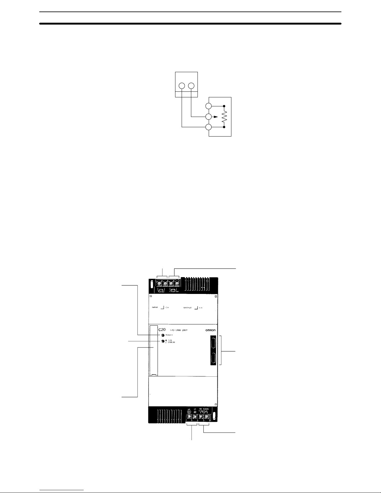
1–1–4 I/O Link Units
The I/O Link Unit must be used as a Remote I/O Slave, and must be used
with a Remote I/O Master. Refer to the Remote I/O Unit Operation Guide for
details.
Operation output terminal
Indicates that the power is ON
and that the CPU is in RUN or
MONITOR mode with no errors.
Repeater Output Terminal
Sends repeater signals to a Link
Adapter. The repeater output is ON
when power is ON in the CPU and
I/O Link Unit. (See the Link Adapter
manual for details.)
Optical fiber connectors
Transmitting error indicator
Blinks during normal transmission.
Lights continuously to indicate a
transmission or connection error.
AC power supply
Ground
CPU or Expansion
I/O Unit connector
Power indicator
Nomenclature Section 1–1
Page 15

7
1–2 System Configuration
Depending on your control requirements, you can combine various Units for
a total number of I/O points ranging anywhere from 20 to 148.
For example, a single C20K CPU, with no Expansion I/O Units connected,
has a total of 20 I/O points, broken down into 12 input points and 8 output
points. If it is used in combination with a C4K Input Unit, there will be a total
of 16 input points and 8 output points. If combined with a C4K Output Unit,
the total will be 12 input points and 12 output points.
If the C20K is combined with a C16P Expansion I/O Unit, there will be a sum
total of 36 I/O points. If the C16P is an Input Unit, they will be broken down
into 28 input points and 8 output points; if it is an Output Unit, there will be 12
input points and 24 output points. For a listing of possible Unit combinations
and numbers of I/O points, see Appendix E System Configuration Chart.
Only one Expansion I/O Unit with the suffix ”P” can be connected to any
given CPU. It is possible to add more than one C4K, but under no circumstances can the total number of I/O points exceed 148. Either one Analog
Timer Unit or one I/O Link Unit can be added to any other possible combination of Units.
When determining which configuration to use, another factor to consider is
the ease with which I/O points can be assigned. In order to make the process
as simple as possible, it is recommended that a CPU be used which has
more I/O points than the largest Expansion I/O Unit. For example, rather than
combining a C20P CPU with a C20P Expansion I/O Unit, it would be preferable to use a C40P CPU. Similarly, combining a C60P CPU with a C40 Expansion I/O Unit would be better than using a C40P CPU and a C60P Expansion I/O Unit.
This is intended only as a brief overview of system configuration possibilities.
In addition to Appendix E System Configuration Chart (mentioned above),
see the I/O tables in the operation manual for details on various possible
combinations of Units and the particular I/O bits and IR area work bits which
are available for use in each configuration.
System Configuration Section 1–2
Page 16

9
SECTION 2
System Installation and Wiring
2–1 General 10. . . . . . . . . . . . . . . . . . . . . . . . . . . . . . . . . . . . . . . . . . . . . . . . . . . . . . . . . . . . . . . . .
2–2 Installation Environment 10. . . . . . . . . . . . . . . . . . . . . . . . . . . . . . . . . . . . . . . . . . . . . . . . . . .
2–3 Dimensions and Installation 12. . . . . . . . . . . . . . . . . . . . . . . . . . . . . . . . . . . . . . . . . . . . . . . . .
2–4 I/O Connecting Cable 16. . . . . . . . . . . . . . . . . . . . . . . . . . . . . . . . . . . . . . . . . . . . . . . . . . . . . .
2–5 Wiring CPUs and Expansion I/O Units 19. . . . . . . . . . . . . . . . . . . . . . . . . . . . . . . . . . . . . . . .
2–6 I/O Wiring 22. . . . . . . . . . . . . . . . . . . . . . . . . . . . . . . . . . . . . . . . . . . . . . . . . . . . . . . . . . . . . .
2–6–1 Unit Wiring Diagrams 22. . . . . . . . . . . . . . . . . . . . . . . . . . . . . . . . . . . . . . . . . . . . . .
2–6–2 I/O Device Connection Examples 38. . . . . . . . . . . . . . . . . . . . . . . . . . . . . . . . . . . . .
2–7 Special Wiring Precautions 39. . . . . . . . . . . . . . . . . . . . . . . . . . . . . . . . . . . . . . . . . . . . . . . . .
2–8 Settings 41. . . . . . . . . . . . . . . . . . . . . . . . . . . . . . . . . . . . . . . . . . . . . . . . . . . . . . . . . . . . . . . . .
2–8–1 Setting the CPU DIP Switch 41. . . . . . . . . . . . . . . . . . . . . . . . . . . . . . . . . . . . . . . . .
2–8–2 EP–ROM Installation 42. . . . . . . . . . . . . . . . . . . . . . . . . . . . . . . . . . . . . . . . . . . . . . .
2–8–3 High–Speed Counter 42. . . . . . . . . . . . . . . . . . . . . . . . . . . . . . . . . . . . . . . . . . . . . . .
2–8–4 Inhibiting the ALARM Indicator 43. . . . . . . . . . . . . . . . . . . . . . . . . . . . . . . . . . . . . .
2–8–5 Setting the I/O Link Unit 43. . . . . . . . . . . . . . . . . . . . . . . . . . . . . . . . . . . . . . . . . . . .
Page 17

10
2–1 General
This section explains how to install and set up your Control System, with specifics on the proper environment, actual mounting, applicable cable, wiring,
and switch settings.
2–2 Installation Environment
Although the K–Type Programmable Controller is quite durable, the following
conditions must be observed in order for your System to operate at its highest level of reliability.
Ambient temperature Operating: 0° to 55°C*
Storage: –20 to 65
°C
Humidity 35% to 85% RH (without condensation)
Must be free from the following:
• Corrosive gases
• Abrupt temperature changes
• Direct sunlight
Atmosphere
• Concentration of dust, salt, iron particles
• Splatter from water, oil, other chemicals
Vibration and shock Must not receive direct impact or vibration
*The ambient operating temperature for the Programming Console is 05 to 455
CAUTION
In low humidity conditions, excessive static electricity of over 8 KV can damage internal components such as ICs. Therefore, before touching the PC, be
sure to first touch a grounded metallic object to discharge any static electricity buildup.
Noise Prevention Use twisted pair cables with cross–sectional areas of at least 2 mm
2
/conductor (AGW 14) to prevent noise. Avoid mounting the PC close to high–power
equipment, and be sure to mount it at least 200 mm away from power lines.
Wherever possible, use wiring ducts to contain and protect the PC wiring.
The I/O wiring should not be placed in the same duct with the power line or
other wiring. Standard wiring conduits are sufficient as long as the I/O wiring
and power lines are kept separate.
200mm
min.
200mm min.
PC
Installation Environment Section 2–2
Page 18
11
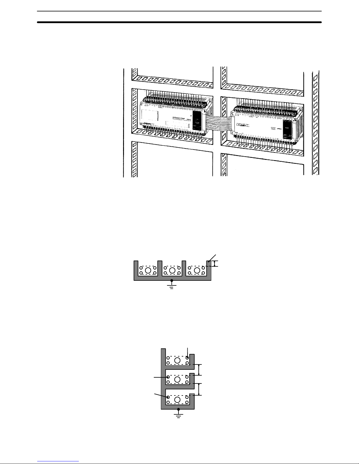
Duct Work When CPUs and Expansion I/O Units are mounted horizontally, be sure that
no ducts or wiring passes between them. The diagram shows an example of
unacceptable mounting.
If the controlled system requires either 10 A at 400 V max. or 20 A at 220 V
max. power cables, and if the conduits are run parallel to each other, a minimum distance of 300 mm must be provided between the I/O lines and the
power cable. If the I/O lines and the power cables must be placed in the
same duct at the point of connection to the equipment, be sure to screen
them with a grounded metal plate.
3
Metal (iron) plate
200 mm min.
Grounding (at a ground resistance of less than 100
Ω )
1 PC I/O circuit
2 PC power circuit
3 General control circuit/Power circuit
1
2
Weak current cable
300 mm min.
300 mm min.
Control cable
Power cable
Ground (at a resistance of
less than 100
Ω )
1
2
3
Installation Environment Section 2–2
Page 19
12
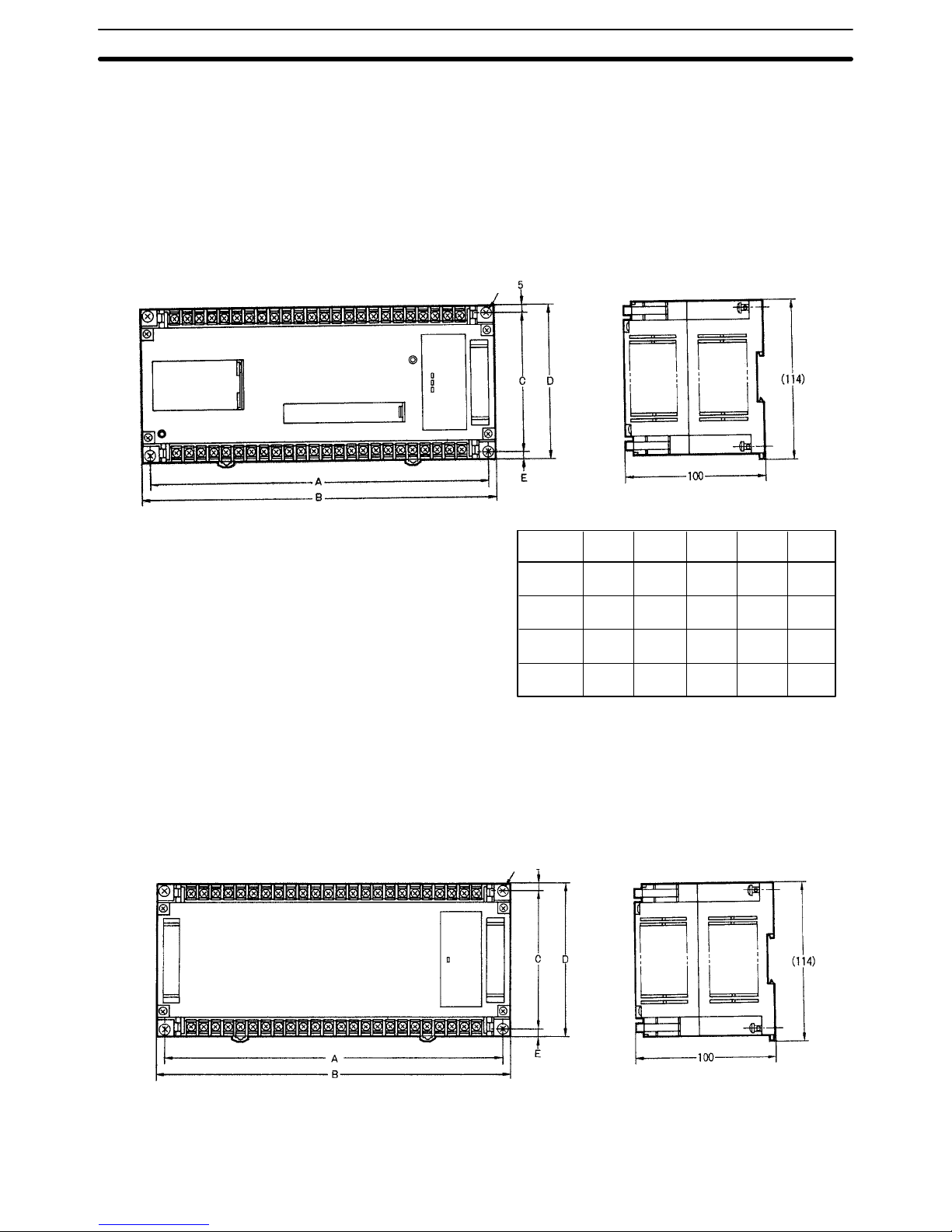
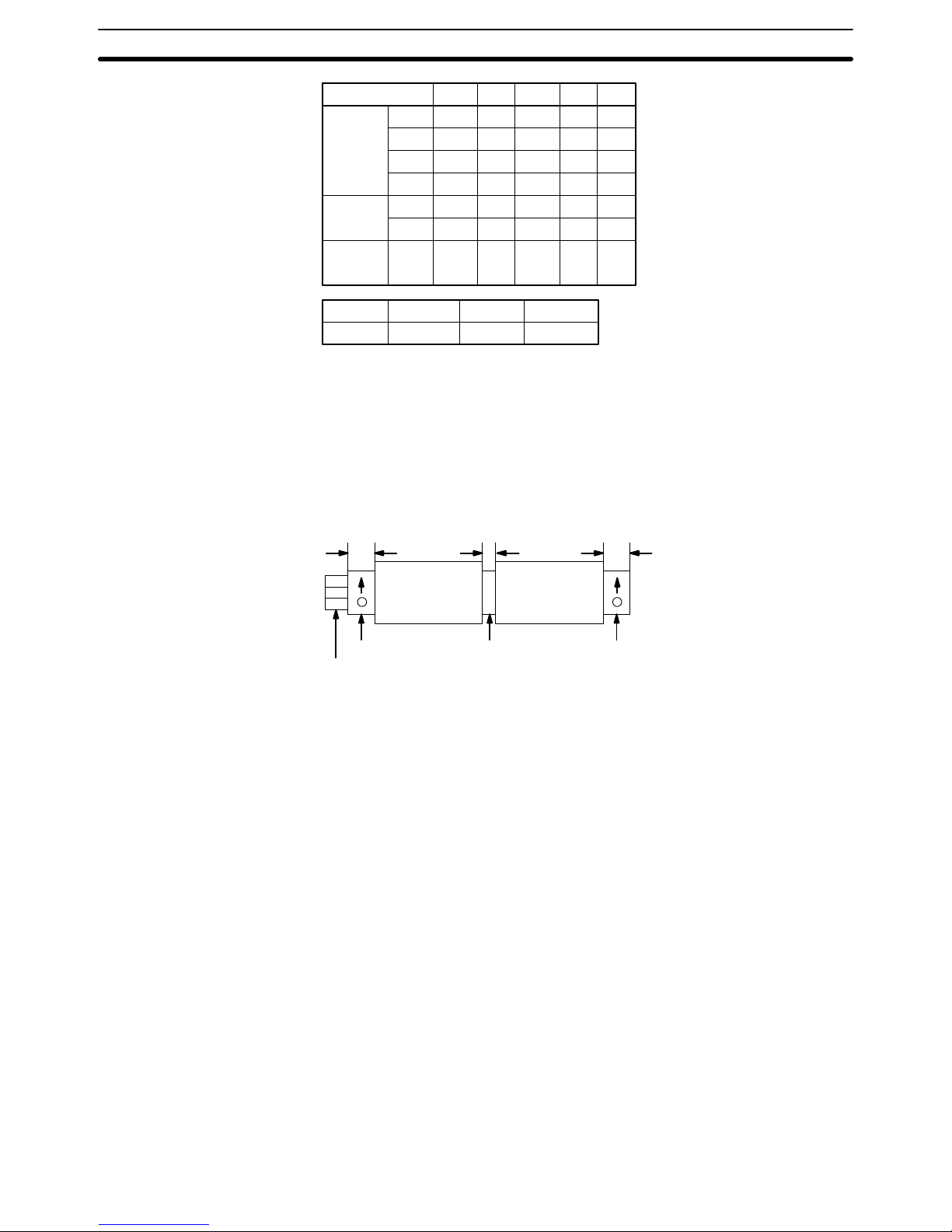
2–3 Dimensions and Installation
This section gives dimensions and other information necessary for mounting
the CPUs, Expansion I/O Units, Analog Timer Units, and I/O Link Units. All
measurements are in mm.
CPUs (The C20K is shown as an example.)
A
240
240
290
340
Model
C20K
C28K
C40K
C60K
B
250
250
300
350
C
100
100
100
120
Four M4 screws
D
110
110
110
140
E
5
5
5
15
Expansion I/O Units (The C20P is shown as an example.)
Four M4 screws
Dimensions and Installation Section 2–3
Page 20
13
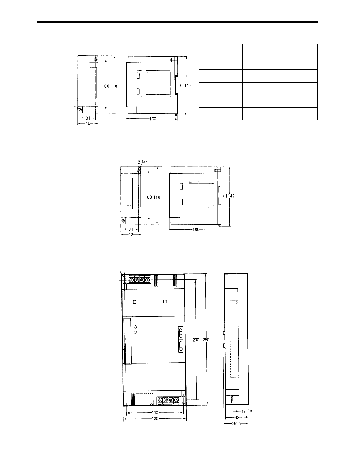
Expansion I/O Units cont.
Model
C16P
C20P
C28P
C40P
C60P
A
145
240
240
290
340
B
155
250
250
300
350
C
100
100
100
100
120
D
110
110
110
110
140
E
5
5
5
5
15
2–M4
C4K
Analog Timer Units C4K–TM
I/O Link Units C20–LK011(–P)
Two M4 holes
Dimensions and Installation Section 2–3
Page 21
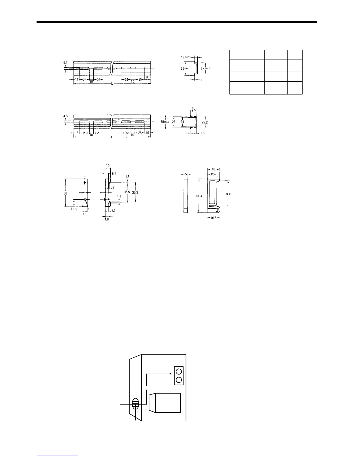
14
DIN Rails
*
5
15
––
Model
PFP–50N
PFP–100N
PFP–100N2
L
50 cm
1 m
1 m
* Use the PFP–100N2 for the C60P.
If the PFP–50N or PFP–100N are
used, the Unit will be slanted.
PFP–50N/PFP–100N
PFP–100N2
Endplate PFP–M
Eight M4
panhead
screws
Spacer PFP–S
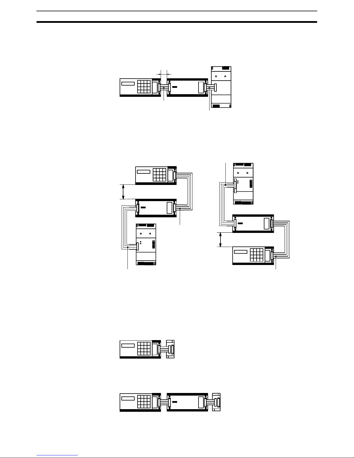
Mounting A CPU and Expansion I/O Unit may be mounted either vertically or horizon-
tally in relation to each other but the orientation of each unit itself must remain horizontal as described by the following mounting diagrams. If mounting
the units vertically, position the CPU above the Expansion I/O Unit; if mounting horizontally, position the CPU to the left.
When installing the CPUs, Expansion I/O Units, and I/O Link Units, allow sufficient space between the Units for cooling. Models taking a 100– to
240–VAC power supply require a minimum cooling space of 10 mm between
Units. Avoid mounting any units in warm areas or over a heat source of any
kind.In addition, if the CPU is installed in a control box, allow sufficient space
for maintenence and ventilation. It may be necessary to install a ventilation
fan in the control box to maintain the required ambient temperature as indicated in Appendix B Specifications.
Control Box
Fan
PC
Vent
Dimensions and Installation Section 2–3
Page 22
15
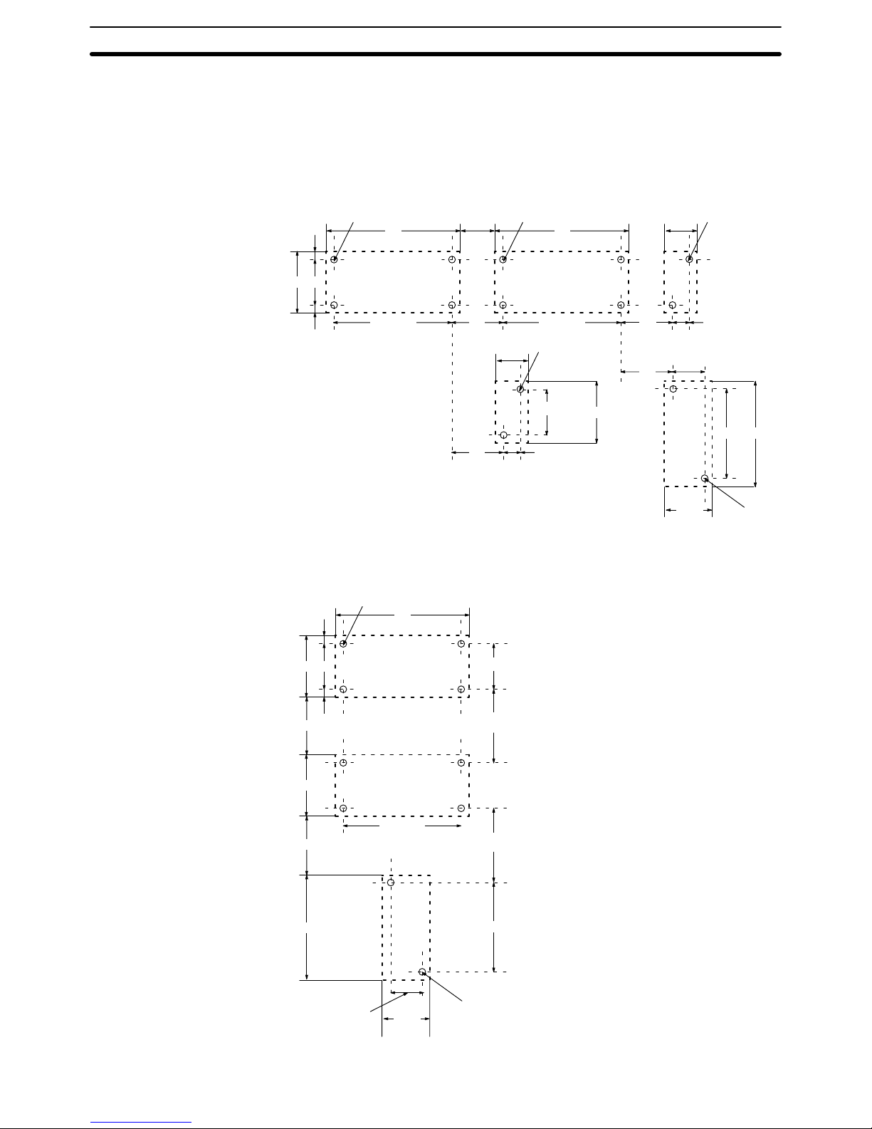
Another factor to consider is the I/O wiring (see 2–5 I/O Wiring). If the CPU
and/or Expansion I/O Units are mounted vertically, a minimum of 70 mm
open space is required for ease of I/O wiring. The spacing of the mounting
holes, for both vertical and horizontal mounting is as shown below.
Horizontal Mounting
A ± 0.2 A ± 0.2
G
A ± 0.2
D C
4–M4 4–M4 2–M4
Expansion
I/O Unit
CPU
Analog
Timer Unit
B B
F–10
A ± 0.2
2–M4
B
F
F
C ± 0.2
D
C4K
230 250
5
E
H
110
± 0.2
120
2–M4
I/O
Link
Unit
Vertical Mounting
D C
4–M4
CPU
B
5
A ± 0.2
Expansion
I/O Unit
D
230
120
2–M4
110 ± 0.2
230
I–10
I–10
C ± 0.2
I
I
I/O
Link
Unit
Dimensions and Installation Section 2–3
Page 23
16
Model
CPU
I/O Unit
I/O Unit
Analog
Timer
Unit
C20K
C28K
C40K
C60K
C16P
C4K
C4K
–TM
A
±0.2
240
240
290
340
145
31
31
B
250
250
300
350
155
40
40
C±0.2
100
100
100
120
100
100
100
D
110
110
110
140
110
110
110
E
5
5
5
15
5
5
5
F
15 to 40G15 to 35H20 to 40I80 to 130
Attach End Plates (PFP–M) to both ends (as shown below) when connecting
CPUs, Expansion I/O Units, or Analog Timer Units to a DIN Rail. It is also
recommended that a Spacer (PFP–S) be installed between a CPU and Expansion I/O Unit when they are mounted horizontally.
XX
510 10
End plate
DIN Rail
Spacer End plate
CPU I/O Unit
Mounting screws are included with CPUs, Expansion I/O Units, and Analog
Timer Units. They must be purchased separately for I/O Link Units.
2–4 I/O Connecting Cable
Applicable connecting cable will vary according to which Units are connected
and whether they are mounted horizontally or vertically. All Expansion I/O
Units except the C16P and C4K use C20P–CN501 cable (5 cm) for horizontal mounting and C20P–CN411 cable (40 cm) for vertical mounting. The
C16P and C4K cannot be mounted vertically. The C16P can use either of the
above–mentioned cables for horizontal mounting. The C4K can use only
C4K–CN501 cable (5 cm). For connecting I/O Link Units, use C20P–CN711
cable (70 cm).
CAUTION:
Always be sure to use only the cable that is included with the Unit. Using the
wrong cable (such as the C20 I/O Connecting Cable or I/O Link Connecting
Cable) for connecting Expansion I/O Units can cause serious damage to the
Units.
I/O Connecting Cable Section 2–4
Page 24
17
The following diagrams illustrate the appropriate cables for connecting CPUs,
Expansion I/O Units, and I/O Link Units either horizontally or vertically.
5 to 30 cm
I/O Connecting
Cable C20P–CN501
100 to 200mm
100 to 200mm
Horizontal Mounting
CPU
I/O Unit
CPU
I/O Unit
I/O Unit
CPU
I/O Link Connecting
Cable C20P–CN711
I/O Link
Unit
I/O Link
Unit
I/O Link
Unit
Vertical Mounting
I/O Connecting
Cable C20P–CN411
I/O Link Connecting
Cable C20P–CN711
I/O Link Connecting
Cable C20–CN711
I/O Connecting
Cable C20P–CN411
One Analog Timer Unit can be connected directly to a CPU or to any combination of a CPU and Expansion I/O Units. In either case, as shown in the following diagram, the Units must be mounted horizontally.
Analog
Timer Unit
Connecting Cable
C4K–CN501
Analog
Timer Unit
Connecting Cable
C4K–CN501
CPU
CPU
I/O Unit
Connecting Cable
C20P–CN501
Connecting Analog Timer
Units
I/O Connecting Cable Section 2–4
Page 25
18
Connecting I/O Link Units One I/O Link Unit can be connected directly to a CPU or to any combination
of a CPU and Expansion I/O Units. It cannot be used in the same PC System
with an Analog Timer Unit.
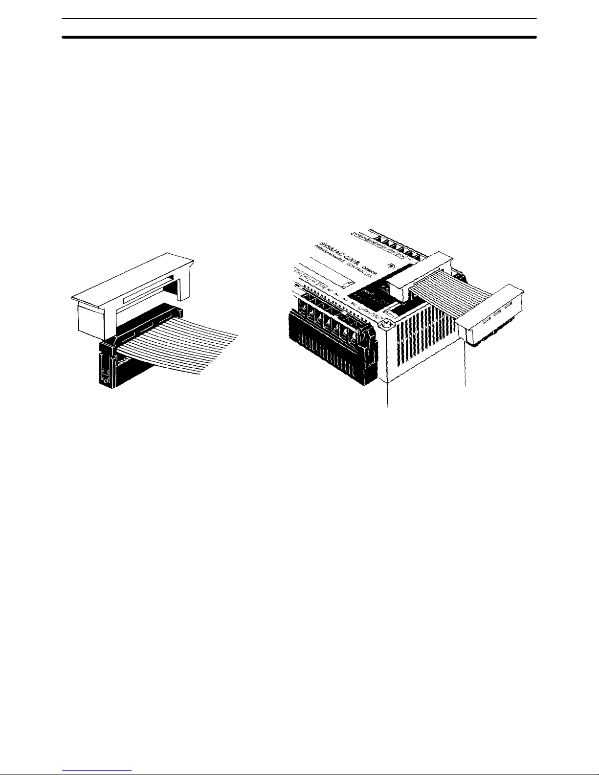
Connection Procedure Follow these four steps to connect Expansion I/O Unit, Analog Timer, and I/O
Link Unit Connecting Cables.
1, 2, 3... 1. Remove the connector cover from the CPU, using a screwdriver if nec-
essary.
2. Insert one of the cable’s connectors into the cover. (Once inserted, the
connector cannot be removed.)
3. Reinsert the cover/connector combination into the CPU.
4. Repeat this procedure on the other end of the cable.
Cover
Optical Fiber Cable Optical fiber cable can be used for extending transmission distance and re-
ducing noise. There are three types, and the appropriate cable for any given
situation will depend on the desired transmission distance and the particular
Units which need to be connected.
All–plastic optical fiber cable (APF) is for short–distance transmission (up to
20 m) and can be used only by Units with the suffix ”–P” attached. Plastic–
clad optical fiber cable (PCF) is for middle–distance transmission (up to 200
m for Units with ”–P” and 800 m for Units without ”–P”). Crystal optical fiber
cable (AGF) is for long–distance transmission (up to 3 km) and can be connected only to certain Link Adapters.
Although laying optical fiber cable does not basically differ from laying wire
cable, there are certain precautions which should be observed. For details,
refer to the Optical Remote I/O Systems manual.
Link Adapters Although it is normally possible to connect Units in series, a failure (power
failure, disconnection, etc.) in one of the Units will cause all the subsequent
Units to cease operating. You can use Link Adapters to prevent this type of
situation from occuring. Even if a power failure occurs in a Unit connected to
a branch line of a Link Adapter, the Link Adapter will bypass that Unit and
continue to transmit signals to the other Units. You can also use Link Adapters for branching and for converting between various types of wire and optical cable. For details on these and other functions of Link Adapters, refer to
the Link Adapter manual.
I/O Connecting Cable Section 2–4
Page 26
19
2–5 Wiring CPUs and Expansion I/O Units
Power Supply Use a commercially available 24–VDC, 100– to 120VAC, or 200– to
240–VAC power supply (depending on your model) for the CPU. When an
Expansion I/O Unit(s) or an I/O Link Unit is used, the power supply must also
be connected to each of these Units. Where possible, use independent
power sources for the inputs, the output loads, and the CPU. All of the CPUs
and Expansion I/O Units may be connected to the same power source. If a
CPU and an Expansion I/O Unit are connected to separate power supplies,
then the CPU (as well as the Programming Console, etc.) will not operate
unless power is turned on to the Expansion I/O Unit.
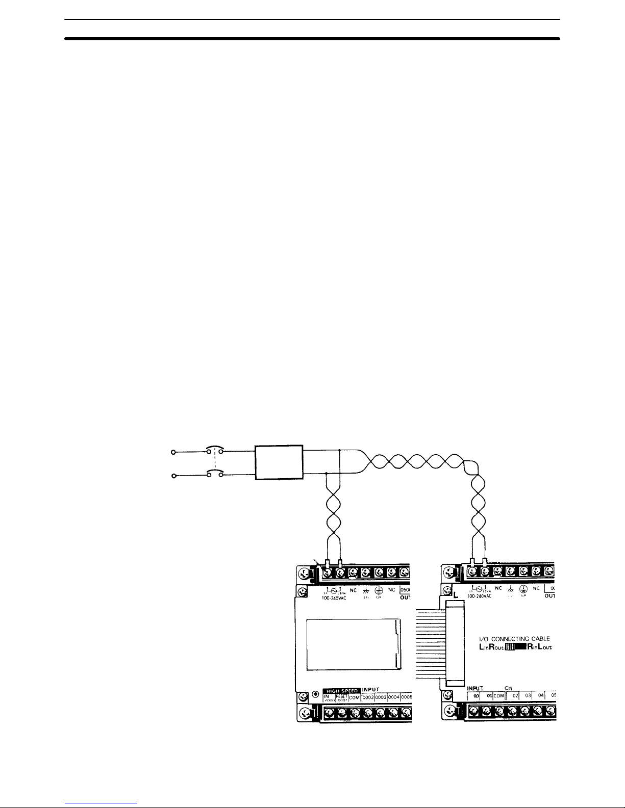
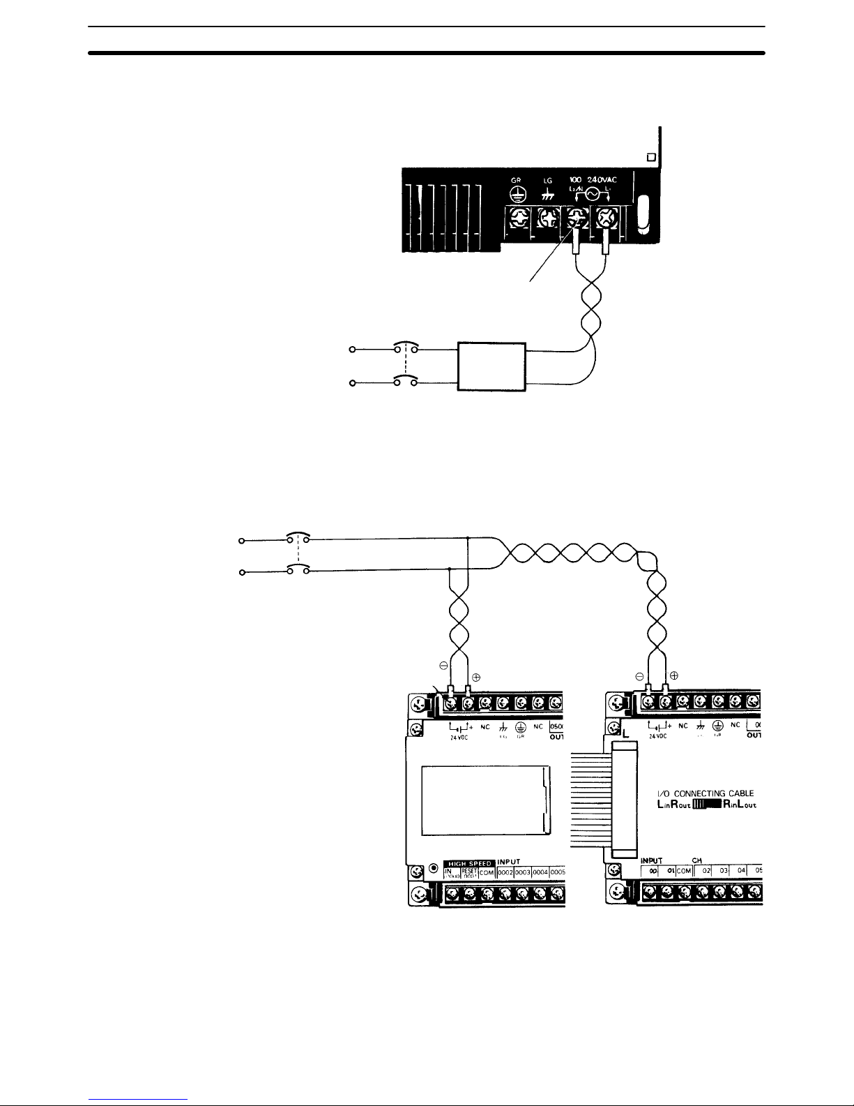
Wiring The following diagram illustrates the proper wiring for CPUs and Expansion
I/O Units with the suffix ”–A.” These models use a power supply of 100 to 240
VAC, with an operating voltage range of 85 to 264 VAC. The internal noise–
reduction system in these Units is sufficient for general power line noise, but
ground noise can be greatly reduced by using a 1:1 insulating transformer.
Ground only the primary side of the transformer. To prevent voltage drop, use
wires 2 mm2 or less in cross sectional area, twisting them as shown in the
diagram. When power is turned on, the incoming current will be approximately 10 A.
Breaker
Insulating
transformer
1:1
M3.5 screws
Wiring CPUs and Expansion I/O Units Section 2–5
Page 27
20
Connect an I/O Link Unit as shown in the following diagram, using M4 terminal screws.
M4 screws
100 to 240 VAC
Insulating
transformer
1:1
Breaker
The following diagram illustrates the proper wiring for CPUs and Expansion
I/O Units with the suffix ”–D.” These models use a power supply of 24 VDC
with an operating voltage range of 20.6 to 26.4 VDC. Be careful to connect
the positive and negative terminals correctly. When power is turned ON, the
incoming current will be approximately 30 A.
Breaker
M3.5 screws
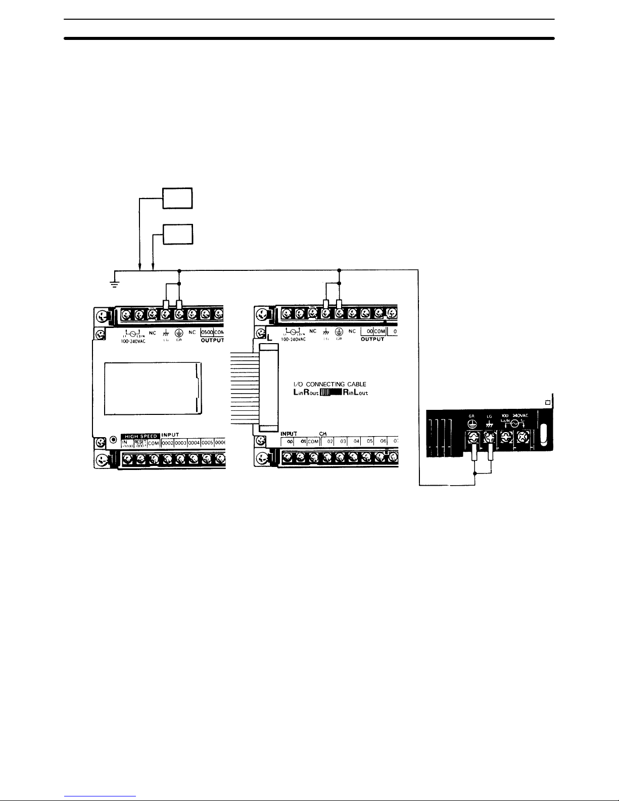
Ground The Line Ground (LG) terminal is a noise filter neutral terminal which does
not normally require grounding. When electrical noise is a problem, however,
this terminal should be connected to the GR terminal.
Attach an independent ground–wire with a cross–sectional area of at least 2
mm
2
(AWG 14) to the GR terminal, to avoid electrical shock. Ground resis-
Wiring CPUs and Expansion I/O Units Section 2–5
Page 28
21
tance must be less than 100 Ω. Do not use a ground–wire longer than 20 m.
Care must be taken because ground resistance is affected by the nature of
the ground, water content, season, and the amount of time that has elapsed
since the wire was laid underground.
CPU operation may be adversely affected if the ground–wire is shared with
other equipment, or if grounding is attempted by attaching the ground–wire to
the metal superstructure of a building. When either Expansion I/O Units or
I/O Link Units are used, they also require grounding at the GR terminal.
These may all be included on the same ground.
LG
GR
Wiring CPUs and Expansion I/O Units Section 2–5
Page 29

22
2–6 I/O Wiring
This section shows I/O wiring diagrams for representative models of all the
CPUs, Expansion I/O Units, and I/O Link Units covered in this manual. It also
gives connection examples for the sensors and switches which can be connected as input devices.
2–6–1 Unit Wiring Diagrams
The following items are all available for use as outputs. Do not mix them
within the same common circuit.
Output
Relay
Transistor
Triac
Load Power Supply
Up to 250 VAC/24 VDC
5 to 24 VDC
100 to 120/200 to 240 VAC
When using transistor outputs, connect the common line (COM) to the load
power supply negative side. For an induction load, connect the diode to the
load in parallel, as shown in the diagram, such that the cathode is on the
positive side of the power supply.
L
OUT COM
+
When using the high–speed counter instruction (HDM(61)), wire input 0000
as the high–speed counter input and input 0001 as the hardware reset input.
If the HDM is not used, inputs 0000 and 0001 may be used as general input
terminals. Their response time (0.15 ms), however, will be shorter than the
other inputs.
Do not connect the NC terminals to anything. The DC inputs in the following
I/O wiring diagrams are NPN (positive common). Reverse the polarity if PNP
(negative common) is used.
In the diagrams, representative models are sometimes used to cover several
models with similar wiring. In such cases, the type of Unit (i.e., CPU C60K) is
listed first, followed by the suffix of the applicable model number. A space left
blank (_) in the model number indicates that any of several numbers could be
inserted there.
I/O Wiring Section 2–6
Page 30

23
The inputs can use the Unit’s 24–VDC power supply output. If the maximum
output current of 0.2 A is not sufficient a separate DC power supply must be
used.
Load
power
supply
Relay contact outputs
Transistor outputs
Triac outputs
Inputs (24 VDC)
M3.5 screws
7.5 max.
Power
supply
(100 to
240 VAC)
NC
NC
Ground
Load
power
supply
Load
power
supply
Load
power
supply
Load
power
supply
Load
power
supply
Load
power
supply
Not in C20K Not in C20K or C28K
Not in C20K
Not in C20K or C28K
High–
speed
counter
input
NC: Do not connect the NC terminals to anything.
COM
24 VDC
output
(0.2 A max.)
7.5 max.
Hardware reset input
CPU C20K, C28K, C40K
(CD_–A)
I/O Wiring Section 2–6
Page 31

24
Inputs 0000 and 0001 can use the Unit’s 24–VDC power supply output. If the
maximum output current of 0.2 A is not sufficient a separate DC power supply must be used. Inputs 0002 to 0107 take a 100–VAC power supply.
0000, 0001
24–VDC inputs
0002 to 0101
100–VAC inputs
Relay contact outputs
Triac outputs
Power
supply
(100 to
240 VAC)
NC
NC
Ground
Not in C20K Not in C20K or C28K
Not in C20K
Not in C20K or C28K
High–
speed
counter
input
24 VDC
output
(0.2 A max.)
100 to 120 VAC
M3.5 screws
7.5 max.
7.5 max.
Load
power
supply
Load
power
supply
Load
power
supply
Load
power
supply
Load
power
supply
Load
power
supply
Load
power
supply
Hardware
reset input
CPU C20K, C28K, C40K
(CA_–A)
I/O Wiring Section 2–6
Page 32

25
A separate power supply must be used for the DC inputs.
Relay contact outputs
Transistor outputs
Inputs (24 VDC)
Power
supply
(24 VDC)
NCNC
Ground
Not in C20K Not in C20K or C28K
Not in C20K
Not in C20K or C28K
High–
speed
counter
input
NC: Do not connect the NC terminals to anything.
COM +
24 VDC
M3.5 screws
7.5 max.
7.5 max.
Load
power
supply
Load
power
supply
Load
power
supply
Load
power
supply
Load
power
supply
Load
power
supply
Load
power
supply
NCNC
Hardware
reset input
CPU C20P, C28P, C40P
(CD_–D)
I/O Wiring Section 2–6
Page 33

26
The inputs can use the Unit’s 24–VDC power supply output. If the maximum
output current of 0.3 A is not sufficient, however, a separate DC power supply
must be used.
Relay contact outputs
Transistor outputs
Triac outputs
Power
supply
(100 to
240
VAC)
Ground
Upper terminal
block
Lower terminal
block
Inputs (24 VDC)
High–
speed
counter
input
Hardware reset input
24_VDC
output
(0.3 A
max.)
M3.5 screws
7.5 max.
7.5 max.
Load
power
supply
Load
power
supply
Load
power
supply
Load
power
supply
Load power
supply
CPU C60K (CD_–A)
I/O Wiring Section 2–6
Page 34

27
CPU C60K (CA_–A) Inputs 0000 and 0001 can use the Unit’s 24–VDC power supply output. If the
maximum output current of 0.3 A is not sufficient, however, a separate DC
power supply must be used. Inputs 0002 to 0115 take a 100–VAC power supply.
Relay contact outputs
Triac outputs
Power
supply
(100 to
240
VAC)
Ground
Load power
supply
Load
power
supply
Load
power
supply
Load
power
supply
Load
power
supply
Upper terminal
block
Lower terminal
block
High–
speed
counter
input
24_VDC
output
(0.3 A
max.)
0000, 0001
24–VDC inputs
0002 to 0115
100–VAC inputs
100 to 120 VAC
M3.5 screws
7.5 max.
7.5 max.
Hardware
reset input
I/O Wiring Section 2–6
Page 35

28
CPU C60K (CD_–D) A separate power supply must be used for the DC inputs.
Relay contact outputs
Transistor outputs
Power
supply
(24
VDC)
Ground
Load power
supply
Load
power
supply
Load
power
supply
Load
power
supply
Load
power
supply
Upper terminal
block
Lower terminal
block
Inputs (24 VDC)
High–
speed
counter
input
Hardware reset input
M3.5 screws
7.5 max.
7.5 max.
I/O Wiring Section 2–6
Page 36

29
The inputs can use the Unit’s 24–VDC power supply output. If the maximum
output current of 0.2 A is not sufficient, however, a separate DC power supply
must be used.
Relay contact outputs
Transistor outputs
Triac outputs
Inputs (24 VDC)
Power
supply
(100 to
240 VAC)
NC
NC
Ground
Not in C20K Not in C20K or C28K
Not in C20K
Not in C20K or C28K
COM
24 VDC
output
(0.2 A max.)
M3.5 screws
7.5 max.
7.5 max.
Load
power
supply
Load
power
supply
Load
power
supply
Load
power
supply
Load
power
supply
Load
power
supply
Load
power
supply
I/O Unit C20P/C28P/C40P
(ED_–A)
I/O Wiring Section 2–6
Page 37

30
I/O Unit C20P/C28P/C40P (EA_–A)
Inputs (100 VAC)
Relay contact outputs
Triac outputs
Power
supply
(100 to
240 VAC)
NC
NC
Ground
Not in C20K Not in C20K or C28K
Not in C20K
Not in C20K or C28K
COM
24 VDC
output
(0.2 A max.)
100 to 120 VAC
M3.5 screws
7.5 max.
7.5 max.
Load
power
supply
Load
power
supply
Load
power
supply
Load
power
supply
Load
power
supply
Load
power
supply
Load
power
supply
A separate power supply must be used for the DC inputs.
Inputs (24 VDC)
Relay contact outputs
Triac outputs
Power
supply
(24 VDC)
Ground
Not in C20K Not in C20K or C28K
Not in C20K
Not in C20K or C28K
M3.5 screws
7.5 max.
7.5 max.
Load
power
supply
Load
power
supply
Load
power
supply
Load
power
supply
Load
power
supply
Load
power
supply
Load
power
supply
NC
NC
I/O Unit C20P/C28P/C40P
(ED_–D)
I/O Wiring Section 2–6
Page 38

31
The inputs can use the Unit’s 24–VDC power supply output. If the maximum
output current of 0.3 A is not sufficient, however, a separate DC power supply
must be used.
Relay contact outputs
Transistor outputs
Triac outputs
Power
supply
(100 to
240
VAC)
Ground
Upper terminal
block
Lower terminal
block
Inputs (24 VDC)
24_VDC
output
(0.3 A
max.)
M3.5 screws
7.5 max.
7.5 max.
Load
power
supply
Load
power
supply
Load
power
supply
Load
power
supply
Load power
supply
100 240VAC
CH(00 15) CH(00 15)
CH(00 15)
CH(00 11)
INPUT
COM
NC NC
NC
I/O Unit C60P (ED_–A)
I/O Wiring Section 2–6
Page 39

32
I/O Unit C60P (EA_–A)
Relay contact outputs
Triac outputs
Power
supply
(100 to
240
VAC)
Ground
Upper terminal
block
Lower terminal
block
Inputs (100 VAC)
24_VDC
output
(0.3 A
max.)
M3.5 screws
7.5 max.
7.5 max.
Load
power
supply
Load
power
supply
Load
power
supply
Load
power
supply
Load power
supply
100 240VAC
CH(00 15) CH(00 15)
CH(00 15)
CH(00 11)
INPUT
COM
NC NC
NC
I/O Unit C60P (ED_–D) A separate power supply must be used for the DC inputs.
Relay contact outputs
Transistor outputs
Power
supply
(24
VDC)
Ground
Upper terminal
block
Lower terminal
block
Inputs (24 VDC)
M3.5 screws
7.5 max.
7.5 max.
Load
power
supply
Load
power
supply
Load
power
supply
Load
power
supply
Load power
supply
Load power
supply
100 240VAC
CH(00 15) CH(00 15)
CH(00 15)
CH(00 11)
INPUT
NC NC
NCNCNC
I/O Wiring Section 2–6
Page 40

33
I/O Unit C16P–ID–A The inputs can use the Unit’s 24–VDC power supply output. If the maximum
output current of 0.2 A is not sufficient, however, a separate DC power supply
must be used.
Inputs (24 VDC)
Power supply (100 to
240 VAC)
Ground
M3.5 screws
7.5 max.
7.5 max.
Input Unit C16P–ID A separate power supply must be used for the DC inputs.
Inputs (24 VDC)
Ground
24 VDC
24 VDC
M3.5 screws
7.5 max.
7.5 max.
NCNC NC
NC NC NC NC
I/O Wiring Section 2–6
Page 41

34
Input Unit C16P–IA
Inputs (100 VAC)
100 to 120 VAC
100 to 120 VAC
M3.5 screws
Ground
7.5 max.
7.5 max.
NC NC NC
NCNC NC NC
Output Unit C16P–O_–A
Load
power
supply
Load
power
supply
Load
power
supply
Load
power
supply
Load
power
supply
Load
power
supply
Relay contact outputs
Transistor outputs
Triac outputs
Power
supply
(100 to
240
VAC)
Ground
M3.5 screws
7.5 max.
7.5 max.
I/O Wiring Section 2–6
Page 42

35
Output Unit C16P–O_–D
Load
power
supply
Load
power
supply
Load
power
supply
Load
power
supply
Load
power
supply
Load
power
supply
Relay contact outputs
Transistor outputs
Power
supply
(24
VDC)
Ground
M3.5 screws
7.5 max.
7.5 max.
Input Unit C4K–ID The C4K–ID can use the 24–VDC output from the CPU if the current (0.3 A)
is sufficient. If this is not sufficient, a separate DC power source must be
used.
Inputs (24 VDC)
24 VDC
24 VDC
M3.5 screws
7.5 max.
7.5 max.
I/O Wiring Section 2–6
Page 43

36
Input Unit C4K–IA
Inputs (100 VAC)
100 to 120 VDC
100 to 120 VAC
M3.5 screws
7.5 max.
7.5 max.
Output Unit C4K–O__
Load
power
supply
Load
power
supply
Relay contact outputs
Transistor outputs
Triac outputs
M3.5 screws
7.5 max.
7.5 max.
I/O Wiring Section 2–6
Page 44

37
I/O Link Unit 3G2C7–LK011(–P)E
RUN output
M4 screws
Repeater output (Used only when connected to Link Adapter.)
Link Adapter
M4 screws
Optical fiber connector
Power supply
(100 to 240 VAC)
8.6 max.
8.6 max.
I/O Wiring Section 2–6
Page 45

38
2–6–2 I/O Device Connection Examples
The following diagrams show connection examples for the sensors and
switches which can be connected as input devices. Be sure to check all input
devices for voltage and amperage compatibility before connecting.
AC Input Devices
Prox
switch
main
circuit
10 mA
100 VAC
IN
COM
AC input
IN
COM –
AC input
Contact output
AC–switching
DC Input Devices
Sensor
power
supply
Sensor
power
supply
Sensor
power
supply
Contact output
7mA
24 VDC
0 V
IN
COM +
DC input
Output
Current
regulator
NPN open–collector
24 VDC
0 V
IN
COM +
DC input
24 VDC
0 V
IN
COM –
24 VDC
0 V
IN
COM +
DC input
DC input
7mA
0 V
NPN Contact output
PNP current output
+
Output
7mA
0 V
+
Output
7mA
0 V
High–Speed Counter Input Devices (Rotary Encoder)
24 VDC
0 V
IN(0000)
COM
24 VDC
0 V
IN (0000)
COM
24 VDC
0 V
IN(0000)
COM
Red
White
Black
Red
White(Green)
Black
Red
White(Green,Yellow)
Black
Shield
High–speed
counter
input
High–speed
counter
input
High–speed
counter
input
E6A–CS4C E6A–CW4C
E6C–CWZ5C
I/O Wiring Section 2–6
Page 46

39
2–7 Special Wiring Precautions
Emergency Stop Circuit An external relay circuit can be constructed to prevent a CPU breakdown or
malfunction from damaging the entire System. In the following diagram, SR
bit 1813 is always closed when the CPU is operating. If the program is set up
as shown in the diagram, then output 0100 will be ON whenever the CPU is
in either RUN or MONITOR mode, and it will function as an output to monitor
whether the CPU is operating properly or not.
1813
0100
Example
Normally
ON
RUN output
An I/O Link Unit’s RUN output terminal is wired to a CPU’s input terminal,
and can function as an output to monitor whether the entire PC System, including the I/O Link Unit, is operating properly or not. In the diagram below,
the I/O Link Unit is connected to input terminal 0002. If the program is set up
as shown in the diagram, then output 0100 wil be ON whenever the CPU is in
either RUN or MONITOR mode. The I/O Link Unit’s RUN output and the
CPU’s RUN or MONITOR output together comprise an AND in the external
relay circuit, and this can be used to construct an emergency stop circuit.
C20P
24 VDC
Output
0002
RUN output
I/O Link Unit
0002 1813
0100
Example
Normally
open (NO)
Emergency Stop Circuit
When an I/O Link Unit is
Used
Special Wiring Precautions Section 2–7
Page 47

40
Interlock Circuit There are sometimes cases in which a PC can direct a machine to do either
of two contrasting actions, and in which damage could result from a malfunction in the PC. For example, the PC could be set up to output commands to a
motor to operate alternately in forward and reverse. In such cases an interlock circuit can be set up to prevent damage in case of a malfunction. In the
example diagram below, the interlock circuit will prevent MC1 and MC2 from
turning ON at the same time even if the PC malfunctions and turns outputs
0101 and 0102 ON simultaneously.
MC1
MC2
Motor forward
Motor reverse
Interlock circuit
PC
0101
0102
Electric power systems, control systems, PC power supply systems, and I/O
power supply systems should all be wired separately, as shown in the following diagram.
CR1
DC power
supply
PC
Control system
Electric power system
PC RUN
output
Twisted pair cable
CR!
+
–
Surge suppressor
MCB2
MCB1
Power Failure Protection A power sequence circuit is incorporated in the PC to prevent malfunctioning
due to momentary power failures or voltage drops.
Wiring of Power Supply
Systems
Special Wiring Precautions Section 2–7
Page 48

41
The PC ignores all momentary power failures if the interruption lasts no
longer than 10 ms. If the interruption is between 10 ms and 25 ms, it may or
may not be detected. If the supply voltage drops below 85% for longer than
25 ms, the PC will stop operating and the external outputs will be automatically turned off. Operation automatically resumes when the supply voltage is
restored to more than 85% of the rated voltage. Detection time will be slightly
shorter when a DC power supply is used.
Momentary power
failure detection
time
Power Supply
Power failure
detection signal
CPU voltage (5V)
Power reset
Run monitor
outputs
Approx. 1 s
2–8 Settings
After writing the program and preparing the EP–ROM chip (see the Operation Manual), the CPU DIP switch must be set and the EP–ROM installed.
2–8–1 Setting the CPU DIP Switch
1, 2, 3... 1. Turn OFF the power to the CPU.
2. Remove the cover from the CPU, using a screwdriver if necessary.
3. Set DIP switch pins 1 and 2 to OFF, and pins 3 and 4 to ON.
ON
OFF
OFF
ON
Settings Section 2–8
Page 49

42
2–8–2 EPROM Installation
1, 2, 3... 1. Remove the cover as shown above.
2. Raise the lever to unlock the socket.
3. Holding the chip so as not to touch the pins, insert it into the socket with
the notch to the left.
4. Check to be sure the chip has been properly installed.
5. Return the lever to its original position, locking the chip in.
6. Replace the cover.
7. Turn the power ON and verify that the CPU is operating in MONITOR
mode.
Lever
I/C Socket
Insert with the notch to the left.
2–8–3 High–speed Counter
When the high–speed counter (HDM(61)) is used, input (0000) is used exclusively for this purpose and responds up to 2 kHz. Either the hardware reset
or software reset may be used. The software reset may be delayed, depending on the cycle time, since it is based on the program. The hardware reset is
unrelated to the cycle time and can operate at high speed. To use the hardware reset (input 0001), set DIP switch pins 7 and 8 to ON as shown below.
Be sure to set them to OFF whenever the hardware reset is not being used,
regardless of whether the high–speed counter is being used or not.
ON
ON
Settings Section 2–8
Page 50

43
2–8–4 Inhibiting the ALARM Indicator
To inhibit the ALARM indicator when using EP–ROM, set DIP switch pin 5 to
ON as shown below.
Connect a backup battery to preserve data memory, current counter value,
and HR area bits, in case of a power failure. In order to maintain the battery,
DIP switch pin 5 should normally be set to OFF. In any case, it must always
be OFF when using RAM.
2–8–5 Setting the I/O Link Unit
In order for the I/O Link Unit to operate, it is necessary to determine the assignment of I/O words between the I/O Link Unit and the Remote I/O Master
Unit controlled by the CPU. This is done with the DIP switch on the I/O Link
Unit. The following explanation is intended only to give a general outline of
the proper procedure. For details, refer to the Optical Remote I/O Systems
manual.
Caution Be certain that power is off before setting the DIP switch. Setting it with the
power ON can cause the Unit to malfunction.
1, 2, 3... 1. Check the last assigned word number on the CPU. When setting the I/O
Link Unit, be sure not to overlap the words or to exceed the number of
I/O points in the CPU.
2. Turn OFF the power to the I/O Link Unit.
3. Check to be sure that the power supply LED light is off. Remove the
cover on the side panel of the Unit, using a screwdriver if necessary.
Settings Section 2–8
Page 51

44
4. Use the 6 DIP switch pins to set the word number from 0 to 30. As
shown in the diagram below, the word numbers are set in binary, with
pin 5 being ”1” and pin 1 being ”16.” Beginning with pin 1, turn ON the
pins required to arrive at the desired number of words. Turn ON pin 6 to
set the termination resistance if the I/O Link Unit is a terminator (the final
Unit in the System). If the Unit is not a terminator, leave pin 6 OFF.
ON
123456
168421
The following example diagram illustrates the proper DIP switch setting for
word 26.
ON
1 2 34 56
16 8 4 2 1
Terminator: ON
Pins 1, 2, and 4, set ON
16 + 8 + 2 =Word 26
5. After initially setting the DIP switches, an I/O table check should be per-
formed on the CPU to ensure that there are no errors in the settings.
6. Replace the cover. In addition, to prevent dirt or outside light from caus-
ing a malfunction, be sure that any unused optical fiber connectors are
covered with the protective caps. The Unit should be ready to operate
as soon as power is turned on. If it does not operate normally, refer to
3–1 Self–Diagnostic Function.
In the diagram below, a C20 CPU, a C40K CPU, a C20P I/O Unit and two I/O
Link Units can exchange data over a distance with a C500 Remote I/O Master Unit. The C20 I/O Link Unit is set for word 28 (which accesses word 29 as
well), and the C40K I/O Link Unit is set for word 30 (which accesses word 31
as well). The C40K I/O Link Unit is also set as the terminator.
C500 CPU Rack
C500 Remote I/O Master Unit
Optical fiber cable Optical fiber cable
C20 CPU I/O Link Unit
C40K CPU C20P I/O Unit
I/O Link Unit
System Configuration
Example
Settings Section 2–8
Page 52

45
When setting the I/O Link Unit, in this example, it is necessary to take into
account not only the I/O words of the C500 Remote I/O Master Unit, but also
those of the C20 CPU and the C40K CPU.
C20P
C20P
C40K
OUT
word 5
IN
word 0
OUT
word 6
IN
word 6
C500 Word Assignment
0
1
2
27
28
29
30
31
Auto-
matic
Man-
ual
C20 Word Assignment C40P Word Assignment
I/O Link
(C20)
I/O Link
(C40K)
OUT word 1, 3
IN word 0, 2 IN word 4
OUT word 5
OUT
word 7
IN
word 1
I/O Link Unit
DIP Switch Setting
Set for Word 28
Not terminator
Set for Word 30
Set as terminator
As seen from C20, C40P
Word 1: 16 input points
Word 6: 16 output points
Data input from C500
Data output to C500
Word 6: 16 input points
Word 7: 16 output points
Data input from C500
Data output to C500
ON
123456
ON
123456
Model
I/O Link
(20)
I/O Link
(40P)
As seen from C20
Word 28: 16 output points
Word 29: 16 input points
Data output to C20
Data input from C20
Word 30: 16 output points
Word 31: input points
Data output to C40K
Data input from C40K
Settings Section 2–8
Page 53

47
SECTION 3
Maintenance and Inspection
3–1 General 48. . . . . . . . . . . . . . . . . . . . . . . . . . . . . . . . . . . . . . . . . . . . . . . . . . . . . . . . . . . . . . . . .
3–2 Self–Diagnostic Functions 48. . . . . . . . . . . . . . . . . . . . . . . . . . . . . . . . . . . . . . . . . . . . . . . . . .
3–3 Replacing Parts 49. . . . . . . . . . . . . . . . . . . . . . . . . . . . . . . . . . . . . . . . . . . . . . . . . . . . . . . . . . .
3–3–1 Fuses 49. . . . . . . . . . . . . . . . . . . . . . . . . . . . . . . . . . . . . . . . . . . . . . . . . . . . . . . . . . .
3–3–2 Relays 50. . . . . . . . . . . . . . . . . . . . . . . . . . . . . . . . . . . . . . . . . . . . . . . . . . . . . . . . . . .
3–3–3 Batteries 51. . . . . . . . . . . . . . . . . . . . . . . . . . . . . . . . . . . . . . . . . . . . . . . . . . . . . . . . .
3–4 Preventive Measures 52. . . . . . . . . . . . . . . . . . . . . . . . . . . . . . . . . . . . . . . . . . . . . . . . . . . . . .
3–5 Inspection 54. . . . . . . . . . . . . . . . . . . . . . . . . . . . . . . . . . . . . . . . . . . . . . . . . . . . . . . . . . . . . . .
Page 54

48
3–1 General
This section explains the proper maintenance and inspection procedures for
the K–Type PCs, including specifics on replacing parts and taking precautionary measures to ensure reliable, trouble–free operation.
3–2 Self–Diagnostic Functions
The K–Type PC has self–diagnostic functions to identify many types of abnormal system conditions. These functions minimize downtime and enable
quick, smooth error correction.
The ERROR light on the front panel of the Programming Console indicates
hardware errors such as CPU, Expansion I/O Unit, and Remote I/O Unit malfunctions. The ALARM light indicates such things as cycle time overrun, battery error, or user–defined errors. The following chart lists possible malfunctions, error messages, and correction procedures.
Correction
Check the power supply voltage and
power lines.
In PROGRAM mode, turn on power
again.
Check the user program again.
Check the program and fix the error.
Rerun the program.
Check that the DIP switch settings
are correct.
Check that the EP–ROM chip is
properly mounted.
Check that the battery is properly
inserted.
Clear the error after fixing it.
Write END in the final address of
the program.
Check that all the lines are properly
connected between the Units.
Check that the CPU Left/Right Selector on the Expansion I/O Unit is
properly set.
Clear the error after fixing it.
Make sure that there are no more
than 8 JMP–JME pairs in the program.
Check battery connections.
Replace battery.
Check the program again.
Situation
Fatal error
Non–fatal
error
Item
Power failure
CPU error (watchdog timer
over 130 ms)
Memory error
Missing END instruction
I/O bus error
JMP over
Battery error
Cycle time overrun (watch-
dog timer 100 to 130 ms)
ALARM
ERROR
Error Display
___
___
MEMORY ERR
NO END INST
I/O BUS ERR
JMP OVER
BATT LOW
CYCLE TIME
OVER
PC LED States
POWER
RUN
Stays lit. Blinks. Not lit.
I/O Link Unit Error
Item
Power failure
Transmission error
I/O Link Unit LED States
Correction
Check the power supply voltage and power lines.
Check connections of the optical fiber cable and connectors.
Check the channel and terminator settings.
POWER
*Note: Blinking ERROR LED indicates normal transmission.
*
ERROR
Self–Diagnostic Functions Section 3–2
Page 55

49
3–3 Replacing Parts
In order that your System be restored to operation as quickly as possible, it is
advisable to maintain an adequate stock of replaceable parts on hand.
CAUTION:
Replace all fuses, relays, and other parts as quickly as possible. If the cover
is left off for a long period the RAM’s contents may be erased.
3–3–1 Fuses
Replace fuses as follows:
1, 2, 3... 1. Turn off power to the Unit.
2. Using a Phillips screwdriver to loosen the 4 screws, remove the cover
from the Unit, lifting it from the left.
Phillips screwdriver
3. Remove the cover from the fuse socket as shown below.
Fuse socket
Fuse cover
Fuse socket
4. Using a standard screwdriver, remove the defective fuses and insert the
new ones.
5. Replace the cover, positioning it over the Unit and snapping it into place
by applying pressure to the area marked ”OMRON.”
The above procedure applies to CPUs and Expansion I/O Units. The procedure is similar for I/O Link Units except that the cover is secured by 4 catches
instead of 4 screws. Use a standard screwdriver to pop the cover off and insert the fuses as shown below.
Replacing Parts Section 3–3
Page 56

50
Catches
Catches
Standard screwdriver
Power fuse
1 A, 250 V
Refer to the chart below in selecting the proper fuses.
Power Supply Fuses φ 5.2 x 20 (MF1NR)
CPU’s,
Expansion
I/O Units
A–suffix
D–suffix
C16P
C20K, C28K, C40K
C60K
C16P
C20K, C28K, C40K
C60K
250 V, 1 A
250 V, 2 A
250 V, 3 A
125 V. 1 A
125 V, 3 A
125 V, 5 A
250 V, 1 A
I/O Link Units
24–VDC Output Fuses φ 5.2 x 20 (MF51NR)
CPUs, Expansion I/O Units
(A–suffix only)
C16P
C20K, C28K, C40K, C60K
125 V, 0.2 A
125 V, 0.5 A
3–3–2 Relays
Replace relays as follows:
1, 2, 3... 1. Turn off power to the Unit.
2. Using a Phillips screwdriver to loosen the 4 screws, remove the cover
from the Unit, lifting it from the left.
3. Using the relay puller attached to the right of the Unit, remove the defective relay and insert the new one.
Replacing Parts Section 3–3
Page 57

51
Relay
Relay puller
4. Replace the cover, positioning it over the Unit and snapping it into place
by applying pressure to the area marked ”OMRON.”
Relays are arranged as follows for the C16P, C20K, C28K, C40K, and C60K.
Among these Units, most models have relay sockets, although certain models do not. The C4K is not shown below; in this Unit the relays are directly
attached.
5601234567 701234 8910118 9 10 1112 1314 15
70123456
C16P C20K C28K
23111098
70123456
01 4 5 6
12 1314 15
891011
7
C40K C60K
012345678910110123
word n word n+1
word n word n+1
3–3–3 Batteries
The service life of the battery (3G2A9–BAT08) is five years at 25° C. It will be
shorter at higher temperatures. The ALARM indicator blinks when the battery
is discharged. If this happens, replace the battery within one week. The date
by which the first battery must be replaced is written on the side panel of the
CPU. If, for example, it says ”FIRST REPLACEMENT 93/12,” it means that
you should replace the battery not later than December 1993.
Caution The new battery must be connected within five minutes of removing the old
to preserve the data in the CPU. In addition, as there is danger of combustion, explosion or leakage, do not attempt to charge, heat or disassemble the
battery, or short–circuit the terminals. When disposing of a used battery, do
not throw it into a fire.
Replace the battery as follows:
1. Turn off the power to the Unit. If the power is off to begin with, turn it on
and wait for at least 10 seconds. Then turn it off.
Replacing Parts Section 3–3
Page 58

52
2. Using a Phillips screwdriver to loosen the 4 screws, remove the cover from
the Unit, lifting it from the left.
3. Pull the battery from the holder and install the new one within five minutes.
Battery in holder
4. Replace the cover, positioning it over the Unit and snapping it into place by
applying pressure to the area marked ”OMRON.”
5. Clear the ALARM on the Programming Console.
3–4 Preventive Measures
Load Circuit Fuses A fuse in the load circuit will protect the output elements, circuit board, etc., in
the event of a short in the output device.
Relay,
solenoid, etc.
+
OUT
COM
When two–wire sensors, such as photoelectric sensors and proximity sensors, or limit switches with neon lamp are connected to the CPU as input devices, the input signal may be erroneously turned ON by a leakage current
over 1.5 A. To prevent this, connect a bleeder resistor as shown below.
Determine the resistance of the bleeder resistor by the following equation,
where I is the leakage current.
Sensor
Input
Power
supply
Bleeder resistor
7.5 k
Ω max.
PC
R
R = 17.15/3.431 + 5 (k
Ω max.)
Likewise, if there is a danger of leakage current causing a transistor or triac
to malfunction, connect a bleeder resistor as shown below. Determine the
resistance of the bleeder resistor by the following equation.
Transistor
Triac
24 VDC
100 VAC
200 VAC
0.1 mA
2.0 mA
5.0 mA
R < Von/I
Von = ON voltage of the load (V)
I = leakage current (mA)
R = bleeder resistance (k
Ω)
L
Load power supply
OUT
COM
Bleeder resistor
Prevention of Input
Leakage Current
Prevention of Output
Leakage Current
Preventive Measures Section 3–4
Page 59

53
When connecting the resistor or triac output to a device (such as an incandescent lamp) which allows a high inrush current to flow, care must be taken
to ensure the safety of the transistor or triac. The transistors and triacs are
able to withstand an inrush current of ten times the rated current. If the actual
inrush current will exceed that amount, use one of the following two circuits
to reduce it.
This circuit allows a slight current
(about 1/3 of the rated current) to
flow through the load (i.e., the
lamp), thus eliminating any initial
surge of current.
This circuit acts directly on the
inrush current to limit it, but also
reduces the voltage across the
load.
L
+
OUT
COM
L
+
OUT
COM
When connecting TTL circuits to transistor outputs, it is necessary (because
of the transistor’s residual voltage) to connect a pull–up resistor and a CMOS
IC between the two.
When an inductive load is connected to the input or output of the CPU, it is
necessary to connect a surge suppressor or a diode in parallel with the load,
as shown below, to absorb the counter–electromotive force produced by the
load.
L
Surge supressor
OUT
COM
Relay, or triac
output
COM
IN
DC Input
L
Diode
L
OUT
COM
Relay, or transistor
output
+
Diode
Resistor: 50 Ω
Capacitor: 0.47 µF
Voltage: 200 V
Diode: Must withstand
voltages more
than three times
the load voltage
and an average
current of 1 A
Precautions for Inrush
Current
Transistor Output Residual
Voltage
Inductive Load Surge
Suppressors
Preventive Measures Section 3–4
Page 60

54
Output Loads Be sure to take appropriate measures when any electrical device likely to
produce noise is connected to the CPU as a load. For example, electromagnetic relays and valves generating noise of more than 1,200 V require noise
suppression. For AC–operated noise sources, connect a surge suppressor in
parallel with the coil of each device. For DC–operated noise sources, connect a diode in parallel with the coil of each device. When mounting a CPU
and an Expansion I/O Unit on a control panel, be sure to completely ground
the intermediate mounting plate. The mounting plate must be finished with
high–conductivity plating to ensure noise immunity.
RR
–
+
Surge
suppressor
AC power source DC power source
Diode
3–5 Inspection
In order for your PC to continue operating at optimum condition, periodic inspections are necessary. The main components of the PC are semiconductors and have a long service life, but, depending on the operating environment, there may be more or less deterioration of these and other parts. A
standard inspection schedule would be once every six months to one year,
but more frequent inspections may be advisable depending on the operating
environment. Try to maintain the inspection schedule once it has been set.
Check to be sure that the power supply, ambient temperature, humidity, and
so on, are within the specifications (see Appendix B). Be sure that there are
no loose screws in any of the Units and that all battery and cable connections
are secure. Clean any dust or dirt that has accumulated. Check all fuses, relays, and other replaceable parts.
Inspection Section 3–5
Page 61

55
Appendix A
Standard Models
There are four K–type C–series CPUs. A CPU can be combined with any of
six types of Expansion I/O Unit and/or an Analog Timer, Analog I/O Unit, or
I/O Link Unit.
CPUs Expansion I/O Units
Analog Timer Unit
Analog I/O Units
I/O Link Unit
C20K–C_ _–_
C28K–C_ _–_
C40K–C_ _–_
C60K–C_ _–_
C4K–I_/O_ _
C4K–TM
C16P–I_–_/O_–_
C20P–E_ _–_
C28P–E_ _–_
C40P–E_ _–_
C60P–E_ _–_
C1K–AD/DA
C4K–AD
C4K–CN502
(included with Unit)
To order cable
separately, specify
C4K–CN502
5 cm or 40 cm
One included with
each Expansion I/O
Unit.
(C20P-CN501/411)
Cable (70 cm)
C20P–CN711
(ordered separately)
C20–LK011/LK011–P
C20K
C28K
C40K
C60K
C20P
C28P
C16P
C60P
C40P
C4K – AD
Page 62

Standard Models Appendix A
56
CPUs
Name Power supply Inputs Outputs Model number
Standards
C20K 100 to 240 VAC 24 VDC, 12 pts Relay w/socket 8 pts C20K–CDR–A U, C
Transistor, 1 A C20K–CDT1–A –––
Triac, 1 A C20K–CDS1–A U, C
24 VDC, 2 pts
100 to 120 VAC,
10 pts
Relay w/socket C20K–CAR–A U, C
Triac, 1A C20K–CAS1–A U, C
24 VDC 24 VDC, 12 pts Relay w/socket C20K–CDR–D U, C
Transistor, 1 A C20K–CDT1–D –––
C28K 100 to 240 VAC 24 VDC, 16 pts Relay w/socket 12 pts C28K–CDR–A U, C
Transistor, 1 A C28K–CDT1–A –––
Triac, 1 A C28K–CDS1–A U, C
24 VDC, 2 pts
100 to 120 VAC,
14 pts
Relay w/socket C28K–CAR–A U, C
Triac, 1A C28K–CAS1–A U, C
24 VDC 24 VDC, 16 pts Relay w/socket C40K–CDR–D U, C
Transistor, 1 A C28K–CDT1–D –––
C40K 100 to 240 VAC 24 VDC, 16 pts Relay w/socket 16 pts C40K–CDR–A U, C
Transistor, 1 A C40K–CDT1–A –––
Triac, 1 A C40K–CDS1–A U, C
24 VDC, 2 pts Relay w/socket C40K–CAR–A C
100 VAC, 22 pts Triac, 1 A C40K–CAS1–A U, C
24 VDC 24 VDC, 24 pts Relay w/socket C40K–CDR–D U, C
Transistor, 1 A C40K–CDT1–D –––
Page 63

Appendix AStandard Models
57
Name
Standards
Model numberOutputsInputsPower supply
C60K 100 to 240 VAC 24 VDC, 32 pts Relay w/socket 28 pts C60K–CDR–A U, C
Transistor, 1 A C60K–CDT1–A –––
Triac, 1 A C60K–CDS1–A U, C
24 VDC, 2 pts Relay w/socket C60K–CAR–A C
100 VAC, 30 pts Triac, 1 A C60K–CAS1–A U, C
24 VDC 24 VDC, 32 pts Relay w/socket C60K–CDR–D U, C
Transistor, 1 A C60K–CDT1–D –––
• U: UL, C: CSA, N: NK
See Omron sales representatives concerning operating conditions under which UL, CSA, and NK standards were met
(Aug. 1988).
I/O Units
Name Power Supply Inputs
Outputs Model Number
Standards
C4K I/O Unit ––– 24 VDC, 4 pts ––– 4 pts. C4K–ID U, C
100 to 120 VAC,
4 pts
––– C4K–IA U, C
––– Relay w/socket C4K–OR2 U, C
Transistor, 1 A C4K–OT2 U, C
Triac, 1A C4K–OS2 U, C
C16P I/O Unit 100 to 240 VAC 24 VDC, 16 pts ––– 16 pts C16P–ID–A U, C
––– Relay w/socket C16P–OR–A U, C
Transistor, 1 A C16P–OT1–A U, C
Triac, 1A C16P–OS1–A U, C
––– 24 VDC, 16 pts ––– C16P–ID U, C
100 to 120 VAC,
16 pts
––– C16P–IA U, C
24 VDC ––– Relay w/socket C16P–OR–D U
Transistor, 1 A C16P–OT1–D U
C20P I/O Unit 100 to 240 VAC 24 VDC, 12 pts Relay w/socket 8 pts C20P–EDR–A U, C, N
Transistor, 1 A C20P–EDT1–A N
Triac, 1A C20P–EDS1–A U, C, N
100 to 120 VAC,
12 pts
Relay w/socket C20P–EAR–A U, C, N
Triac, 1A C20P–EAS1–A U, C, N
24 VDC 24 VDC, 12 pts Relay w/socket C20P–EDR–D U, C, N
Transistor, 1 A C20P–EDT1–D –––
Page 64

Standard Models Appendix A
58
Name Standards
Model NumberOutputs
InputsPower Supply
C28P I/O Unit 100 to 240 VAC 24 VDC, 16 pts Relay w/socket 12 pts C28P–EDR–A U, C, N
Transistor, 1 A C28P–EDT1–A N
Triac, 1A C28P–EDS1–A U, C, N
100 to 120 VAC,
16 pts
Relay w/socket C28P–EAR–A
U, C
Triac, 1A C28P–EAS1–A U, C, N
24 VDC 24 VDC, 16 pts Relay w/socket C28P–EDR–D U, C, N
Transistor, 1 A C28P–EDT1–D –––
C40P I/O Unit 100 to 240 VAC 24 VDC, 24 pts Relay w/socket 16 pts C40P–EDR–A U, C, N
Transistor, 1 A C40P–EDT1–A –––
Triac, 1A C40P–EDS1–A U, C, N
100 to 120 VAC,
24 pts
Relay w/socket C40P–EAR–A U, C, N
Triac, 1A C40P–EAS1–A U, C, N
24 VDC 24 VDC, 24 pts Relay w/socket C40P–EDR–D U, C, N
Transistor, 1 A C40P–EDT1–D –––
C60P I/O Unit 100 to 240 VAC 24 VDC, 32 pts Relay w/socket 28 pts C60P–EDR–A –––
Transistor, 1 A C60P–EDT1–A –––
Triac, 1A C60P–EDS1–A –––
100 VAC, 32 pts Relay w/socket C60P–EAR–A –––
Triac, 1A C60P–EAS1–A –––
24 VDC 24 VDC, 32 pts Relay w/socket C60P–EDR–D –––
Transistor, 1 A C60P–EDT1–D –––
• U: UL, C: CSA, N: NK
See Omron sales representatives concerning operating conditions under which UL, CSA, and NK standards were met
(Aug. 1988).
Page 65

Appendix AStandard Models
59
Special Units
Name Specifications Model number Standards
Analog Timer Unit Settings: 0.1 s to 10 min (one cable, C4K–CN502, in-
cluded)
C4K–TM –––
Analog Timer External
Connector
2–m cable and connector C4K–CN223 –––
Analog Input Unit 1 input; input ranges: 4 to 20 mA, 1 to 5 V C1K–AD –––
4 inputs; input ranges: 4 to 20 mA, 1 to 5 V C4K–AD –––
Analog Output Unit 1 output; output ranges: 4 to 20 mA, 1 to 5 V C1K–DA –––
Host Link Unit RS–232C C20/C20K/C28K/C40K/C60K 3G2C7–LK201–EV1 –––
RS–422 3G2C7–LK202–EV1 –––
I/O Link Unit APF/PCF C20–LK011–P –––
PCF C20–LK011 –––
I/O Connecting Cable For horizontal mounting; cable length: 5 cm
(for maintenance)
C20P–CN501 –––
For vertical mounting; cable length: 40 cm
(for maintenance)
C20P–CN411 –––
I/O Connecting Cable For horizontal mounting; connects to
C4K I/O Units, Analog Timer Unit, or
Cable length:
5 cm
C4K–CN501 –––
Analog I/O Units (for maintenance)
Cable length:
50 cm
C4K–CN512 –––
Cable length:
1 m
C4K–CN122 –––
I/O Link Connecting
Cable
Cable length: 70 cm; for I/O Link Units only C20P–CN711 –––
EPROM 2764 ROM–H –––
Battery Set Built into CPU (same for all C–Series PCs) 3G2A9–BAT08 –––
Relay 24–VDC contact relay G6B–1174P–FD–US U, C
24–VDC transistor relay G3SD–Z01P–PD–US U, C
24–VDC triac relay G3S–201PL–PD–US U, C
• U: UL, C: CSA, N: NK
See Omron sales representatives concerning operating conditions under which UL, CSA, and NK standards were met
(Aug. 1988).
Page 66

Standard Models Appendix A
60
DIN Products
Name Specifications Model number Standards
DIN Track Length: 50 cm Not usable with C60K PFP–50N
Length: 1 m PFP–100N –––
PFP–100N2
End Plate ––– PFP–M
Spacer ––– PFP–S
Factory Intelligent Terminal (FIT)
Name Specifications Model number Standards
FIT 1. FIT Computer
2. SYSMATE Ladder Pack (2 system disks, 1 data disk)
3. MS–DOS
4. GPC Communications Adapter (C500–IF001)
5. Peripheral Connecting Cable (3G2A2–CN221)
6. Power Cord and 3–pin/2–pin plug
7. Carrying Case
FIT10–SET11–E –––
Graphic Programming Console (GPC)
Name Specifications Model number Standards
GPC (LCD display) W/battery; power supply: 32 kw, 100 VAC; w/comments;
System Memory Cassette ordered separately.
3G2C5–GPC03–E
W/battery; power supply: 32 kw, 200 VAC; w/comments;
System Memory Cassette ordered separately.
3G2C5–GPC04–E
GPC Carrying Case W/side pocket for accessories C500–CS001
GPC System Memory
Cassette
For K–Type PCs W/comments 3G2C5–MP304–EV3
–––
Cassette Interface Unit Used to load programs in V8, M1R, M5R, POR, or S6
cassettes into the GPC and print them out through a
Printer Interface Unit.
3G2A5–CMT01–E
• U: UL, C: CSA, N: NK
See Omron sales representatives concerning operating conditions under which UL, CSA, and NK standards were met
(Aug. 1988).
Page 67

Appendix AStandard Models
61
Peripheral Devices
Name Specifications Model number Standards
Programming Console Vertical, w/backlight 3G2A5–PRO13–E U, C
Horizontal, w/backlight 3G2A6–PRO15–E –––
Hand–Held, w/backlight. The Programming Console
Adapter AP003 and connecting cable CN222/CN422 are
necessary. They are sold separately.
C200H–PR027–E U, C
Programming Console
Mounting Bracket
Used to attach Hand–Held Programming Console to a
panel.
C200H–ATT01 –––
Programming Console For C20K/C28K/C40K/C60K 1 m 3G2C7–CN122 –––
Connecting Cables 50 cm 3G2C7–CN512 –––
For Hand–Held Programming Console 2 m C200H–CN222 U, C
4 m C200H–CN422 U, C
Programming Console
Adapter
Attached to PC when connecting Programming Console
via cable (for 3G2A5–PRO13–E or 3G2A6–PRO15–E).
3G2A5–AP001–E –––
Required to use Hand–Held Programming Console. 3G2A5–AP003 –––
Programming Console
Base
Attached to Programming Console when connecting Programming Console via cable.
3G2A5–BP001 –––
Cassette Recorder
Connecting Cable
Used to connect Programming Console, GPC, or
Cassette Deck Interface Unit to a cassette deck; length:
1 m.
SCYPOR–PLG01 –––
PROM Writer Used for all K–Type PCs. C500–PRW06 –––
Printer Interface Unit Interface for X–Y plotter or printer; System Memory
Cassette ordered separately.
3G2A5–PRT01–E –––
Memory Rack K–Type PCs w/comment printing function C500–MP102–EV3
K–Type PCs C20–MP009–EV3
Printer Connecting Cable 2 m (also used for X–Y plotter) SCY–CN201 –––
Floppy Disk Interface Unit C20K/C28K/C40K/C60K. GPC required; w/comment file;
able to connect to NEC floppy disk controller
3G2C5–FDI03–E –––
Peripheral Interface Unit To connect GPC or FIT to K–Type PCs 3G2C7–IP002–V2
Connecting Cable Used to connect FIT or GPC to
Peripheral Interface Unit and to
2 m 3G2A2–CN221 –––
connect Programming Console 5 m 3G2A5–CN523
Adapter and Programming Console 10 m 3G2A5–CN131
Base. 20 m 3G2A5–CN231
30 m 3G2A5–CN331
40 m 3G2A5–CN431
50 m 3G2A5–CN531
• U: UL, C: CSA, N: NK
See Omron sales representatives concerning operating conditions under which UL, CSA, and NK standards were met
(Aug. 1988).
Page 68

63
Appendix B
Specifications
General Ratings
Supply voltage
Operating voltage range
Power consumption
24–VDC output *
Insulation resistance
Dielectric strength
Noise immunity
Vibration
Shock
Ambient temperature
Humidity
Grounding
Structure
Weight CPUs
Expan. I/O Units
Dimensions (CPUs and
Expan. I/O Units)
–A suffix: 100 to 240 VAC 50/60 Hz
–D suffix: 24 VDC
–A suffix: 85 to 264 VAC
–D suffix: 20.4 to 26.4 VDC
–A suffix: 60 VA max.
–D suffix: 40 W max.
0.3 A 24 VDC
±10% (Use as DC power supply)
10 M
Ω min. (at 500 VDC) betweeen AC terminals and housing
2,000 VAC 50/60 Hz for 1 minute (between AC terminals and housing)
500 VAC 50/60 Hz for 1 minute (between DC terminals and housing)
1,000 V p–p, pulse width: 100 ns to 1 µs, rise time 1 ns
10 to 35 Hz, 2 mm double amplitude, in X, Y, and Z directions; 2 hours each. (When
mounted on a DIN rail: 16.7 Hz, 1 mm double amplitude, in X, Y, and Z directions, 1 hour
each.)
10 G in X, Y, and Z directions, 3 times each
Operating: 0
° to 55°C
Storage: –20
° to 65°C
35% to 85% RH (without compensation)
Less than 100
Ω
IEC IP–30 (mounted in a panel)
C20K, C28K: 1.9 kg max; C40K: 2.2 kg max.; C60K: 2.6 kg max.
C20P, C28P: 1.7 kg max.; C40P: 2.0 kg max.; C60P: 2.4 kg max.
C20K, C28K: 250(w) x 110(h) x 100(d); C40K: 300(w) x 110(h) x 100(d);
C60K: 350(w) x 140 (h) x 100 (d)
* This output is not provided on models with the suffix –D in the model number (models accepting a DC supply voltage).
Page 69

Specifications Appendix B
64
CPU Characteristics
MPU, C–MOS, LS–TTL
Ladder diagram
1 address/instruction, 6 bytes/instruction
49
10
µs/instruction (average)
1,194 addresses
136 (1000 to 1807)
1804 to 1806 are reserved for RDM: FUN60 if it is used.
1807 is reserved as software reset input for HDM: FUN 98 if it is used.
16 (1808 to 1907)
Normally–ON, normally–OFF, battery failure, initial cycle ON, 0.1–s pulse, 0.2–s pulse,
1.0–s pulse, etc.
160 (HR 000 to 915)
8 (TR0 to 7)
64 (DM words 00 to 63)
DM words 00 to 31 are reserved as upper and lower limit setting areas for RDM: FUN 60 if
it is used. DM words 32 to 63 are reserved as upper and lower limit setting areas for HDM:
FUN 61 if it is used.
48 (total of TIMs, CNTs, and CNTRs)
TIM 00 to 47 (0 to 999.9 s)
TIMH 00 to 47 (0 to 99.99 s)
CNT 00 to 47 (0 to 9999 counts)
CNTR 00 to 47 (0 to 9999 counts)
CNT 46 is used for RDM(60), and CNT 47 is used for HDM(61). When these instructions
are not used, CNT 46 and 47 can be used for other purposes.
Count input: 0000 High-speed counter specifications apply to
Hardware reset input: 0001 counters created with HDM(61) only.
Software inset: 1807
Maximum response frequency: 2 kHz
Preset count range: 0000 to 9999
Number of outputs: 16
Reset: 1804 Reversible drum counter specifications apply to
Count input: 1805 counters created with RDM(60) only.
Reverse input: 1806
Preset count range: 0000 to 9999
Number of outputs: 16
Status of HR bits, present value of counters, and contents of DM bits are retained during
power failure.
5 years at 25
°C
Battery life is shortened at temperatures higher than 25
°C. Replace battery with new one
within 1 week when ALARM indicator blinks.
CPU failure (watchdog timer)
Memory failure
I/O bus failure
Battery failure, etc.
Program check (executed on start of RUN operation)
END instruction missing
JMP–JME error
Coil duplication
Circuit error
DIFU/DIFD over error
IL/ILC error
Main control elements
Programming method
Instruction length
Number of instructions
Execution time
Memory capacity
IR bits
SR bits
HR bits
TM bits
DM words
Timer/counters
High–speed counter
Reversible drum counter
Memory protection
Battery life
Self–diagnostic features
Program check
Page 70

Appendix BSpecifications
65
Input Specifications
DC input (photocoupler–isolated)
24 VDC ±10%
3 k
Ω
7 mA at 24 VDC
15 VDC min.
5 VDC max.
2.5 ms max. (input 0000 and 0001: 0.15 ms)
2.5 ms max. (input 0000 and 0001: 0.15 ms)
Supply voltage
Input voltage
Input current
ON voltage
OFF voltage
ON delay time
OFF delay time
AC input* (photocoupler–isolated)
100 to 120 VAC + 10%, –15% 50/60 Hz
9.7 k
Ω (50 Hz), 8 kΩ (60 Hz)
10 mA at 100 VAC
60 VAC min.
20 VAC max.
35 ms max.
55 ms max.
+
+ 24
VDC
IN
Internal
Circuit
Photocoupler
3 k
Ω
470 Ω
COM
IN
Internal
Circuit
Photocoupler
330
Ω
COM
100 to
120
VAC
330 k
Ω
180 Ω
0.33 µF
* Inputs 0000 and 0001 operate on DC input voltage. The circuit configuration of these two points is the same as the DC input circuit
shown above.
Note : The 24 VDC power source can be connected to either the positive or the negative terminal. Therefore both PNP input (negative
common) and NPN (positive common) can be used.
Output Specifications
24
VDC
COM
COM
Internal Circuit
X
OUT
L
250 VAC
Load power supply
L
Internal Circuit
OUT
Load power supply
+
5 to 24 VDC
L
COM
Internal Circuit
OUT
Load power supply
+
100 to 120/
200 to 240
VAC
Relay
(photocoupler–
isolated)
Transistor*
(photocoupler–
isolated)
Triac*
(photocoupler–
isolated)
ON–delay
15 ms max.
1.5 ms max.
1.5 ms max.
OFF–delay
15 ms max.
1.5 ms max.
1/2 of load
frequency +
1 ms max.
Circuit configuration
Max.
2 A at 250 VAC
2 A at 24 VDC
(p.f. 1)
0.5 A at 250 VAC
(p.f.0.4)
4 A/Common (4 points/Common)
6 A/Common (8 points/Common)
1 A/point at 5 to
24 VDC,
1.6 to 4 A/4 points
4 A/Common (4 points/Common)
6 A/Common (8 points/Common)
1 A/point at 85 to
250 VAC,
1.6 to 4 A/4 points
4 A/Common (4 points/Common)
6 A/Common (8 points/Common)
Min.
10 mA at
5 VDC
10 mA at
5 VDC,
saturation
voltage:
1.5 V max.
10 mA at
100 VAC,
20 mA at
200 VAC
Switching capacity
Page 71

Specifications Appendix B
66
I/O Link Units
Supply voltage
Operating voltage range
Power consumption
Insulation resistance
Dielectric strength
Noise immunity
Vibration
Shock
Ambient temperature
Humidity
Grounding
Structure
Weight
Dimensions
100 to 120/200 to 240 VAC 50/60 Hz
85 to 132/ 170 to 264 VAC
15 VA max.
10 M
Ω min. (at 500 VDC) between AC terminals and housing
2,000 VAC 50/60 Hz for 1 minute (between AC terminals and housing)
1,000 V p–p, pulse width: 100 ns to 1
µs, rise time: 1 ns
10 to 35 Hz, 2 mm double amplitude, in X, Y, and Z directions, 2 hours each
10 G in X, Y, and Z directions, 3 times each
Operating: 0
° to 55°C
Storage: –20
° to 65°C
35% to 85% RH (without condensation)
Less than 100
Ω
IEC IP–30 (mounted in a panel)
1 kg max.
120(w) x 250(h) x 43(d)
Relay Service Life (at
Maximum Switching
Capacity)
Electical
Mechanical
300,000 operations [under resistive load (p.f. 1)]
100,000 operations [under inductive load (p.f. 0.4)]
50,000,000 operations
Transistor and Triac
Specifications
Max. switching capacity
Min. switching capacity
Leakage current
Residual voltage
ON–delay time
OFF–delay time
Transistor G3SD–Z01P–PD–US
1 A at 5 to 24 VDC
10 mA at 5 VDC
100
µA at 24 VDC
1.5 V max.
1.5 ms max.
1.5 ms max.
Triac G3S–201PL–PD–US
1 A at 85 to 250 VAC
10 mA at 100 VAC
20 mA at 200 VAC
2 mA at 100 VAC
5 mA at 200 VAC
1.5 V max.
1.5 ms max.
1/2 of load frequency + 1 ms max.
Do not mix output devices within the same common circuit.
Page 72

Appendix BSpecifications
67
Transistor Inrush
Current
10 30 50 100 200 500 1000 5000
Current–carrying time (ms)
Inrush Current (A)
3
2
1
0
Transistor and Triac
Maximum Load Current
The maximum load current for the four common circuits varies with the ambient temperature and is 4 to 1.6 A within a range of 20° to 55°C as shown below. Do not exceed the current value indicated in the chart at any given temperature.
Max. total current
of 4 circuits
6
5
4
3
2
1
0
20 40 55
Ambient temperature (
°C)
4 A
1.6 A
Ambient Temperature vs. Total Load Current of Each Common Circuit
Page 73

Specifications Appendix B
68
Analog Timer Unit
Specifications
Bit
00
01
02
03
04
05
06
07
08
09
10
11
12
13
14
15
Word n
Time–up contact T0
Time–up contact T1
Time–up contact T2
Time–up contact T3
Cannot be used
Word(n + 5)
T0 Start
T1 Start
T2 Start
T3 Start
T0 Pause
T1 Pause
T2 Pause
T3 Pause
T0 Range
T1 Range
T2 Range
T3 Range
Item
Oscillation method
Time setting range
Timer pause
function
Number of timer
contacts
Indicators
External variable
resistor
Point number
assignment
Programming and
timing chart
Specifications
RC oscillation
Use the program to set any of the following four ranges, according to the chart shown below.
0.1 to 1 second
1 to 10 seconds
10 to 60 seconds
1 to 10 minutes
The timing operation can be paused if so specified by theprogram. therefore, the timers can also
be used as cumulative timers.
4
SET and TIME UP
External variable resaistors can be used to set the time value when the IN/EXT selector is set to
EXT. Use 20 k
Ω external variable resistors
Word n “1” when time is up
Word (n + 5) “1” when time is set
0 Operates
1 Stops
Timer
no.
T0
T1
T2
T3
Bit
06
09
10
11
12
13
14
15
0.1 to
1 s
0
0
0
0
0
0
0
0
1 to
10 s
1
0
1
0
1
0
1
0
10 to
60 s
0
1
0
1
0
1
0
1
1 to
10 m
0
1
0
1
0
1
0
1
Word n 00 to 03
Timer start input
Timer up output
Timer start
00 to 03,
Word(n +1)
Time–up
Word n 00 to 03
Timer start
input
Timer–up
output
Page 74

69
Appendix C
Programming Console Operations
Mode
Operation
Key Sequence
RUN MON. PROG.
Clearing
Memory
No No Yes
Setting
and
Reading
from
Program
Memory
Address
Yes Ye s Ye s
Checking
the
Program
No No Yes
Yes Ye s Ye s
Program
Searches
Inserting
and Deleting Instructions
No No Yes
Page 75

Programming Console Operations Appendix C
70
Mode
Operation Key Sequence
RUN MON. PROG.
Displaying and
Clearing
Error
Messages
Yes Ye s Ye s
Bit/Digit
Monitor
Yes Ye s Ye s
Force Set/
Reset
No Yes Yes
Hexadecimal/BCD
Data Modification
No Yes Yes
Changing
Timer/
Counter
SV
No Yes No
Saving
Program
Memory
Data
No No Yes
No No YesRestoring or
Comparing
Program
Memory
Data
Page 76

71
Area IR SR HR TR TC DM #
Bits/Words 0000 to 1807 1808 to 1907 HR 000 to 915 TR 0 to 7 TC 00 to 47 DM 00 to DM 63 0000 to 9999
or 0000 to FFFF
Appendix D
Programming Instructions
Ladder Diagram Instructions
Name
Mnemonic
Symbol Function Operands
Load
LD
LD B
Used to start instruction block with status of designated bit.
B:
IR
SR
HR
TC
TR
Load Inverse
LD NOT
LD NOT B
Used to start instruction block with inverse of designated bit.
B:
IR
SR
HR
TC
TR
AND
AND
AND B
Logically ANDs status of designated bit
with execution condition.
B:
IR
SR
HR
TC
TR
AND Inverse
AND NOT
AND NOT B
Logically ANDs inverse of designated
bit with execution condition.
B:
IR
SR
HR
TC
TR
OR
OR
OR B
Logically ORs status of designated bit
with execution condition.
B:
IR
SR
HR
TC
TR
OR Inverse
OR NOT
OR NOT B
Logically ORs inverse of designated bit
with execution condition.
B:
IR
SR
HR
TC
TR
Block AND
AND LD
AND LD –
Logically ANDs results of preceding
blocks.
None
Page 77

Programming Instructions Appendix D
72
Area IR SR HR TR TC DM #
Bits/Words 0000 to 1807 1808 to 1907 HR 000 to 915 TR 0 to 7 TC 00 to 47 DM 00 to DM 63 0000 to 9999
or 0000 to FFFF
Name
Mnemonic
OperandsFunctionSymbol
Block OR
OR LD
OR LD –
Logically ORs results of preceding
blocks.
None
Output
OUT
B
OUT B
Turns ON designated bit. B:
IR
HR
TR
Output
Inverse
OUT NOT
OUT NOT B
B
Turns OFF designated bit. B:
IR
HR
TR
Timer
TIM
TIM
TIM N
SV
N
SV
ON–delay (decrementing) timer operation. Set value: 999.9 s; accuracy:
+0.0/–0.1 s. Same TC bit cannot be
assigned to more than one timer/counter. The TC bit is input as a constant.
N:
TC
SV:
IR
HR
#
Counter
CNT
CNT N
SV
CNT
N
SV
A decrementing counter. SV: 0 to 9999;
CP: count pulse; R: reset input. The
TC bit is input as a constant.
N:
TC
SV:
IR
HR
#
Special Instructions
Name
Mnemonic
Symbol Function Operands
No Operation
NOP (00)
None
Nothing is executed and next instruction is moved to.
None
End
END(01)
END(01)
Required at the end of the program. None
Interlock
IL(02)
Interlock
Clear
ILC(03)
IL(02)
ILC(03)
If interlock condition is OFF, all outputs
are turned OFF and all timer PVs reset
between this IL(02) and the next
ILC(03). Other instructions are treated
as NOP; counter PV are maintained.
None
Page 78

Appendix DProgramming Instructions
73
Area IR SR HR TR TC DM #
Bits/Words 0000 to 1807 1808 to 1907 HR 000 to 915 TR 0 to 7 TC 00 to 47 DM 00 to DM 63 0000 to 9999
or 0000 to FFFF
Name
Mnemonic
OperandsFunctionSymbol
Jump
JMP(04)
Jump End
JME(05)
JMP(04)
JME(05)
Cause all instructions between
JMP(04) and the corresponding
JME(05) to be ignored. Corresponding
JME is next one in program; only 8
JMP–JME pairs allowed per program.
None
Single Step
STEP(08)
STEP(08) N
STEP(08)
Is used in the definition of program
sections. STEP N marks the beginning
of the section identified by N. STEP
without an operand indicates the end
of a series of program sections.
N:
HR
Step
Advance
SNXT(09)
SNXT(09) N
SNXT resets the timers and clears the
data areas used in the previous program section. SNTX must also be
present at the end of a series of program sections.
N:
HR
Shift
Register
SFT(10)
I
P
R
SFT(10)
St
E
Creates a bit shift register from the
starting word (St) through the ending
word (E). I: input bit; P: shift pulse; R:
reset input. St must be less than or
equal to E and Bg and E must be in the
same data area.
E
St
15 150
IN
0
St/E:
IR
HR
Latching
Relay
KEEP(11)
S
KEEP
B
R
Defines a bit (B) as a latch controlled
by set (S) and reset (R) inputs.
B:
IR
HR
Reversible
Counter
CNTR (12)
II
DI
R
N
SV
CNTR
Increases or decreases PV by one
whenever the increment input (II) or
decrement input (DI) signal goes from
OFF to ON. SV: 0 to 9999; R: reset input. Must not access the same TC bit
as another timer/counter. The TC bit is
input as a constant.
N:
TC
SV:
IR
HR
#
Differentiate
Up
DIFU(13)
Differentiate
Down
DIFD(14)
DIFU(13)
DIFD(14)
B
B
DIFU turns ON the designated bit (B)
for one cycle on the rising edge of the
input signal; DIFD turns ON the bit for
one cycle on the trailing edge. The
maximum number of DIFU/DIFDs is
48.
B:
IR
HR
High–speed
Timer
TIMH(15)
TI
TIMH
N
SV
A high–speed ON–delay (decrementing) timer. SV: 0.01 to 99.99 s; accuracy: +0.00/–0.01 s. Must not be assigned the same TC bit as another timer/counter. The TC bit is input as a
constant.
N:
TC
SV:
IR
HR
#
Page 79

Programming Instructions Appendix D
74
Area IR SR HR TR TC DM #
Bits/Words 0000 to 1807 1808 to 1907 HR 000 to 915 TR 0 to 7 TC 00 to 47 DM 00 to DM 63 0000 to 9999
or 0000 to FFFF
Name
Mnemonic
OperandsFunctionSymbol
Word Shift
WSFT(16)
WSFT(16)
St
E
Shifts data between the start and end
words in word units.
St/E:
IR
HR
DM
Compare
CMP(20)
CMP(20)
Cp1
Cp2
Compares two sets of four–digit hexadecimal data (Cp1 and Cp2) and outputs result to GR, EQ, and LE.
Cp1/Cp2:
IR
SR
HR
TC
DM
#
Move
MOV(21)
MOV(21)
S
D
Transfers source data (S) (word or
four–digit constant) to destination word
(D).
S:
IR
SR
HR
TC
DM
#
D:
IR
HR
DM
Move Inverse
MVN(22)
MVN(22)
S
D
Inverts source data (S) (word or four–
digit constant) and then transfers it to
destination word(D).
S:
IR
SR
HR
TC
DM
#
D:
IR
HR
DM
BCD to
Binary
BIN(23)
BIN(23)
S
R
Converts four–digit, BCD data in
source word (S) into 16–bit binary
data, and outputs converted data to result word (R).
S R
x10
0
x10
1
x10
2
x10
3
x16
0
x16
1
x16
2
x16
3
(BCD) (BIN)
S:
IR
SR
HR
TC
DM
R:
IR
HR
DM
Binary to
BCD
BCD(24)
BCD(24)
S
R
Converts binary data in source word (S)
into BCD, and outputs converted data to
result word (R).
x16
0
x16
1
x16
2
x16
3
x10
1
x10
2
x10
3
S R
(BIN) (BCD)
x10
0
S:
IR
SR
HR
DM
R:
IR
HR
DM
BCD Add
ADD(30)
ADD(30)
Au
Ad
R
CY CY
Adds two four–digit BCD values (Au
and Ad) and content of CY, and outputs result to specified result word (R).
Au + Ad +
R
Au/Ad:
IR
SR
HR
TC
DM
#
R:
IR
HR
DM
Page 80

Appendix DProgramming Instructions
75
Area IR SR HR TR TC DM #
Bits/Words 0000 to 1807 1808 to 1907 HR 000 to 915 TR 0 to 7 TC 00 to 47 DM 00 to DM 63 0000 to 9999
or 0000 to FFFF
Name
Mnemonic
OperandsFunctionSymbol
BCD
Subtract
SUB(31)
SUB(31)
Mi
Su
R
Subtracts both four–digit BCD subtrahend (Su) and content of CY from
four–digit BCD minuend (Mi) and outputs result to specified result word (R).
CY CYMi – Su
R
Mi/Su:
IR
SR
HR
TC
DM
#
R:
IR
HR
DM
BCD Multiply
MUL(32)
MUL(32)
Md
Mr
R
Multiplies a words data or a four–digit
BCD value(Md) and another words
data (Mr) and outputs the result to a
specified result word (R).
Md X Mr R
R + 1
Md/Mr:
IR
SR
HR
TC
DM
#
R:
IR
HR
DM
BCD Divide
DIV(33)
DIV(33)
Dd
Dr
R
Divides a words data or a four–digit
BCD dividend (Dd) and another words
data (Dr) and outputs result to specified result word (R).
R
R + 1
Dd/Dr:
IR
SR
HR
TC
DM
#
R:
IR
HR
DM
Set Carry
STC(40)
STC(40)
Sets carry flag (i.e., turns CY ON). None
Clear Carry
CLC(41)
CLC(41)
CLC clears carry flag (i.e, turns CY
OFF).
None
Reversible
Drum Counter
RDM(60)
RDM(60)
D
High–speed UP–DOWN counter operation.
D:
IR
HR
DM
High–speed
Drum
Counter
HDM(61)
HDM(61)
D
A 2–kHz counter with both software
and hardware resets.
D:
IR
HR
DM
End Wait
ENDW(62)
ENDW(62)
N
Used to force a cycle time longer than
normal causing the CPU to wait.
N:
IR
HR
TC
DM
#
Network
Identifier
NETW(63)
NETW(63)
#
Used to leave comments in the program.
#
Page 81

Programming Instructions Appendix D
76
Area IR SR HR TR TC DM #
Bits/Words 0000 to 1807 1808 to 1907 HR 000 to 915 TR 0 to 7 TC 00 to 47 DM 00 to DM 63 0000 to 9999
or 0000 to FFFF
Name
Mnemonic
OperandsFunctionSymbol
4 to 16
Decoder
MLPX(76)
MLPX(76)
S
Di
R
Converts up to four hexadecimal digits
in source word (S) into decimal values
from 0 to 15 and turns ON, in result
word(s) (R), bit(s) corresponding to
converted value. Digits designated in
Di digits (rightmost digit: first digit to be
converted; next digit to left: number of
digits to be converted minus 1).
S
3 2 1 030 to F
Di
S:
IR
SR
HR
TC
DM
Di:
IR
HR
TC
DM
#
R:
IR
HR
DM
16 to 4
Encoder
DMPX(77)
DMPX(77)
S
R
Di
Determines position of highest ON bit in
source word(s) (starting word: S) and
turns ON corresponding bit(s) in result
word (R). Digit designations made with Di
digits (rightmost digit: first digit to receive
converted value; next digit to left: number
of words to be converted minus 1).
.
S
15 0
3
0
R 3 2 1 0 0 to F
S:
IR
SR
HR
TC
DM
R:
IR
HR
DM
Di:
IR
HR
TC
DM
#
Reversible
Shift
Register
SFT(84)
SFTR(84)
C
St
E
Shifts data in a specified word or series
of words one bit to either the left or the
right.
St/E:
IR
HR
DM
C:
IR
HR
DM
Subroutine
Entry
SBS(91)
SBS(91) N
Transfers control of a program over to
a subroutine N.
N:
00 to 15
Subroutine
Definition
Start
SBN(92)
SBN(92) N
Indicates the beginning of a subroutine
definition.
N:
00 to 15
Subroutine
Definition
End
RET(93)
RET(93)
Indicates the end of a subroutine definition.
None
I/O Refresh
IORF(97)
IORF(97)
St
E
Refreshes I/O words between a specified range. Refreshes words in word
units.
St/E:
00 to 09
Page 82

77
Appendix E
System Configuration Chart
A K-type PC can be configured with a CPU Unit and one or more of the following Units: Expansion I/O Units,
Analog Timer Units, or an I/O Link Unit. All of these Units are connected in series with the CPU Unit at one
end. An I/O Link Unit, if included, must be on the other end (meaning only one I/O Link Unit can be used) and
an Analog Timer Unit cannot be used. The rest of the Units can be in any order desired.
There is a restriction in the number of Units which can be included. To compute the number of Units for this
restriction, add up all of the Units counting the C40K CPU Unit, C60K CPU Unit, C40K Expansion I/O Unit and
C60K Expansion I/O Unit as two Units each and any other Units as one Unit each. This total must be no more
than five.
The following table shows some of the combinations that can be used to achieve specific numbers of I/O
points. The numbers in the table indicate the number of Units of that size to be used as either the CPU or Expansion I/O Unit; any one of the Units can be the CPU Unit. This table does not include the C4P or C16P Expansion I/O Units, the Analog Timer Unit, or the I/O Link Unit, which can be used for greater system versatility
or special applications. Refer to the remaining tables in this section for other combinations.
I/O points Count as 2
each
Count as 1
each
Total In Out
C60_
(32/28)
C40_
(24/16)
C28_
(16/12)
C20_
(12/8)
20 12 8 ––– ––– ––– 1
28 16 12 ––– ––– 1 –––
40 24 16
––– ––– ––– 2
––– 1 ––– –––
48 28 20 ––– ––– 1 1
56 32 24 ––– ––– 2 –––
60
32 28 1 ––– ––– –––
36 24
––– ––– ––– 3
––– 1 ––– 1
68 40 28
––– ––– 1 2
––– 1 1 –––
76 44 32 ––– ––– 2 1
80 48 32
––– ––– ––– 4
––– 1 ––– 2
––– 2 ––– –––
1 ––– ––– 2
84 48 36 ––– ––– 3 –––
88
48 40 1 ––– 1 –––
52 36
––– ––– 1 3
––– 1 1 1
96 56 40
––– ––– 2 2
––– 1 2 –––
100 56 44
1 ––– ––– 2
1 1 ––– –––
I/O points Count as 2
each
Count as 1
each
Total In Out
C60_
(32/28)
C40_
(24/16)
C28_
(16/12)
C20_
(12/8)
100 60 40
––– ––– ––– 5
––– 1 ––– 3
––– 2 ––– 1
104 60 44 ––– ––– 3 1
108
60 48 1 ––– 1 1
64 44
––– ––– 1 4
––– 1 1 2
––– 2 1 –––
112 64 48 ––– ––– 4 –––
116
64 52 1 ––– 2 –––
68 48
––– ––– 2 3
––– 1 2 1
120
64 56 2 ––– ––– –––
68 52
1 ––– ––– 3
1 1 ––– 1
124 72 52
––– ––– 3 2
––– 1 3 –––
128 72 56
1 ––– 1 2
1 1 1 –––
132 76 56 ––– ––– 4 1
136 76 60 1 ––– 2 1
140
76 64 2 ––– ––– 1
80 60 ––– ––– 5 –––
144 80 64 1 ––– 3 –––
148 80 68 2 ––– 1 –––
Page 83

System Configuration Chart Appendix E
78
The tables on the following pages show the possible configurations for a K-type PC. Although the tables
branch to show the various possibilities at any one point, there can be no branching in the actual PC connections. You can choose either branch at any point and go as far as required, i.e., you can break off at any point
to create a smaller PC System.When implementing a system there is a physical restriction on the total cable
length allowable. The sum of the lengths of all cables in the system must be limited to less than 1.2 meters.
The tables also show which words will be input words and which words will be output words. All of these are
determined by the position of the Unit in the configuration except for the C4P and C16P Expansion I/O Units,
in which case the model of the Unit determines whether the words are input or output.
The symbols used in the table represent the following:
C20K/C28K
Input Output
C40P/C60P
Input Output Input Output
C20P/C28P/TU/LU,
Input Output
C4K/C16P
In/Output
C40K/C60K
Input Output
Input Output
C20K or C28K CPU Unit
C40K or C60K CPU Unit
C4P or C16P Expansion I/O Unit
C20P Expansion I/O Unit, C28K Expansion I/O Unit,
Analog Timer Unit, or I/O Link Unit
C40P or C60P Expansion I/O Unit
Page 84

Appendix ESystem Configuration Chart
79
C20K/C28K
Input Output
C40P/C60P
Input Output Input Output
C20P/C28P/TU/LU
Input Output
C20P/C28P/TU/LU
Input Output
C20P/C28P/TU/LU
Input Output
C20P/C28P/TU/LU
Input Output
C20P/C28P/TU/LU
Input Output
C20P/C28P/TU/LU
Input Output
C20P/C28P/TU/LU
Input Output
C40P/C60P
Input Output Input Output
C40P/C60P
Input Output Input Output
C20P/C28P/TU/LU
Input Output
C20P/C28P/TU/LU
Input Output
C20P/C28P/TU/LU
Input Output
C20P/C28P/TU/LU
Input Output
C20P/C28P/TU/LU
Input Output
C40P/C60P
Input Output Input Output
C4K/C16P
In/Output
C4K/C16P
In/Output
C4K/C16P
In/Output
C4K/C16P
In/Output
C4K/C16P
In/Output
C4K/C16P
In/Output
C4K/C16P
In/Output
C4K/C16P
In/Output
C4K/C16P
In/Output
C4K/C16P
In/Output
C4K/C16P
In/Output
C4K/C16P
In/Output
C4K/C16P
In/Output
IR 00 IR 01 IR 02 IR 03 IR 04 IR 05 IR 06 IR 07 IR 08 IR 09
Page 85

System Configuration Chart Appendix E
80
C20K/C28K
Input Output
C40P/C60P
Input Output Input Output
C20P/C28P/TU/LU
Input Output
C20P/C28P/TU/LU
Input Output
C20P/C28P/TU/LU
Input Output
C20P/C28P/TU/LU
Input Output
C20P/C28P/TU/LU
Input Output
C40P/C60P
Input Output Input Output
C40P/C60P
Input Output Input Output
C40P/C60P
Input Output Input Output
C20P/C28P/TU/LU
Input Output
C20P/C28P/TU/LU
Input Output
C20P/C28P/TU/LU
Input Output
C20P/C28P/TU/LU
Input Output
C4K/C16P
In/Output
C4K/C16P
In/Output
C4K/C16P
In/Output
C4K/C16P
In/Output
C4K/C16P
In/Output
C4K/C16P
In/Output
C4K/C16P
In/Output
IR 00 IR 01 IR 02 IR 03 IR 04 IR 05 IR 06 IR 07 IR 08 IR 09
Page 86

Appendix ESystem Configuration Chart
81
C40P/C60P
Input Output Input Output
C20P/C28P/TU/LU
Input Output
C20P/C28P/TU/LU
Input Output
C20P/C28P/TU/LU
Input Output
C20P/C28P/TU/LU
Input Output
C20P/C28P/TU/LU
Input Output
C20P/C28P/TU/LU
Input Output
C40K/C60K
Input Output
Input Output
C40K/C60K
Input Output
Input Output
C20P/C28P/TU/LU
Input Output
C40P/C60P
Input Output Input Output
C20P/C28P/TU/LU
Input Output
C20P/C28P/TU/LU
Input Output
C40P/C60P
Input Output Input Output
C20P/C28P/TU/LU
Input Output
C4K/C16P
In/Output
C4K/C16P
In/Output
C4K/C16P
In/Output
C4K/C16P
In/Output
C4K/C16P
In/Output
C4K/C16P
In/Output
C4K/C16P
In/Output
C4K/C16P
In/Output
IR 00 IR 01 IR 02 IR 03 IR 04 IR 05 IR 06 IR 07 IR 08 IR 09
Page 87

Page 88

83
Index
A
Analog Timer Units
connecting, 17
dimensions, 13
mounting, 12, 16
nomenclature, 5—7
specifications, 68
System configuration, 7
C
cable, 10
connection procedure, 18
I/O Connecting Cable, and CPU left/right selector, 4
I/O connecting cable
for Analog Timer Units, 17
for Expansion I/O Units, 17
for I/O Link Units, 17
types of, 16
optical fiber
connectors, 6, 44
types, 18
separation, 11
wiring ducts, 10, 11
CPU left/right selector, 4
CPUs
DIP switch, 41
I/O wiring, 22
mounting, 12, 14, 16
power supply, 19, 20
specifications, 63
D
dimensions
for mounting, 12—18
of Analog Timer Units, 13
of DIN rails, 14
of Expansion I/O Units, 12
of I/O Link Units, 13
DIN Rails
connecting Units, 16
dimensions, 14
DIP switch
on I/O Link Units, 43—45
on PCs, 3, 41, 43
E
emergency stop circuit, 39
environment
ambient temperature, 14, 54
humidity, 10, 54
specifications, 63
installation, 10
noise, 10, 18, 19, 54
specifications, 63
static electricity, 10
EPROM, See ROM, 3
errors
correction procedures, 48
hardware, 48
messages, 48
power failure, 41, 43
cycle time overrun, 48
self–diagnostic functions, 48
user–defined, 48
Expansion I/O Units
dimensions, 12
I/O wiring, 22
indicators, 4
mounting, 4, 12, 14, 16
nomenclature, 3—7
power supply, 19, 20, 29, 30, 31, 32, 33, 35
specifications, 63
System configuration, 7
F–H
fuses, 49—54
grounding, 20
high–speed counter, 22, 42
input terminals, 2
instruction, 2
I
I/O Link Units
connecting, 18
dimensions, 13
DIP switch, 43, 44
I/O wiring, 22
indicators, 6
mounting, 12
nomenclature, 6
power supply, 19
specifications, 66
System configuration, 7
Page 89

Index
84
I/O points
assignment, 7
maximum number, 7
I/O wiring diagrams, 22—38
I/O words, assignment of, 43, 44
indicators
on Expansion I/O Units, 4
on PCs, 2
input devices, 22, 38
leakage current, 52
inrush current, 53
instruction set, table form, 71
interlock circuit, 40
L–O
Link Adapters, 6, 18
mounting
horizontal, 14, 15
screws, 16
space between Units, 14
vertical, 14, 15
nomenclature, 2—7
CPUs, 2—7
output devices, 22, 52
leakage current, 52
relays, 49, 50—54, 65
transistors, 22, 53, 65, 66
triacs, 65, 66
P
PCs
DIP switch, 3, 41, 43
indicators, 2
memory, 2
nomenclature, 2—7
power supply, 23, 24, 25, 26, 27, 28
power supply, 19, 20
batteries, 51
inspection, 54
specifications, 63
systems, wiring of, 40
programming, instruction table, 71
Programming Console, 48, 52, 69
R–S
RAM, 49
memory capacity, 2
usage, 2
Remote I/O Master Units, 6
Remote I/O Slave Units, 6
reset
hardware, 2, 22, 42
software, 42
ROM
EPROM installation, 3, 41, 42—45
memory capacity, 2
usage, 2
surge suppressors, 53
system configuration, 7
Page 90

85
Revision History
A manual revision code appears as a suffix to the catalog number on the front cover of the manual.
Cat. No. W147-E1-2B
Revision code
The following table outlines the changes made to the manual during each revision. Page numbers refer to the
previous version.
Revision code Date Revised content
1 --- ---
2 April 1990 Changes made to pages 16, 39, 54, 68, 70
Put into the current manual format.
Some graphics were replaced with more detailed graphics.
2A May 1993 Pages ix and 7: Maximum number of I/O points possible corrected to 148.
Pages 16, 17, 55, and 59: C4K-CN502 corrected to C4K-CN501.
Page 61: PROM Writer model number updated to C500-PRW06.
Page 64: Instructions for which the high-speed counter and reversible drum
counter specifications are applicable were clarified.
Pages 77 and 78: Entire appendix was recreated and expanded.
2B August 1993 Scan time has been changed to cycle time throughout the manual.
Page 39: SR bit 1813 corrected from “open” to “closed” and the following
example corrected to “Normally ON.”
Page 91

OMRON Corporation
Control Devices Division H.Q.
Shiokoji Horikawa, Shimogyo-ku,
Kyoto, 600-8530 Japan
Tel: (81)75-344-7109/Fax: (81)75-344-7149
Regional Headquarters
OMRON EUROPE B.V.
Wegalaan 67-69, NL-2132 JD Hoofddorp
The Netherlands
Tel: (31)2356-81-300/Fax: (31)2356-81-388
OMRON ELECTRONICS LLC
1 East Commerce Drive, Schaumburg, IL 60173
U.S.A.
Tel: (1)847-843-7900/Fax: (1)847-843-8568
OMRON ASIA PACIFIC PTE. LTD.
83 Clemenceau Avenue,
#11-01, UE Square,
Singapore 239920
Tel: (65)6835-3011/Fax: (65)6835-2711
OMRON (CHINA) CO., LTD.
Room 2211, Bank of China Tower,
200 Yin Cheng Zhong Road,
PuDong New Area, Shanghai, 200120 China
Tel: (86)21-5037-2222/Fax: (86)21-5037-2200
Page 92

Authorized Distributor:
Cat. No. W147-E1-02B Note: Specifications subject to change without notice.
This manual is printed on 100% recycled paper.
Printed in Japan
 Loading...