

Omron C200H-PID01, SYSMAC C200H-PID0, C200H-PID02, C200H-PID03, SYSMAC C200H-PID01 Operation Manual
...
Cat. No. W241-E1-2
SYSMAC
C200H–PID0_
PID Control Unit
C200H-PID0j
PID Control Unit
Operation Manual
Revised March 2000

Notice:
OMRON products are manufactured for use according to proper procedures by a qualified operator
and only for the purposes described in this manual.
The following conventions are used to indicate and classify precautions in this manual. Always heed
the information provided with them. Failure to heed precautions can result in injury to people or damage to property.
DANGER Indicates an imminently hazardous situation which, if not avoided, will result in death or
!
serious injury.
WARNING Indicates a potentially hazardous situation which, if not avoided, could result in death or
!
serious injury.
Caution Indicates a potentially hazardous situation which, if not avoided, may result in minor or
!
moderate injury, or property damage.
OMRON Product References
All OMRON products are capitalized in this manual. The word “Unit” is also capitalized when it refers
to an OMRON product, regardless of whether or not it appears in the proper name of the product.
The abbreviation “Ch,” which appears in some displays and on some OMRON products, often means
“word” and is abbreviated “Wd” in documentation in this sense.
The abbreviation “PC” means Programmable Controller and is not used as an abbreviation for anything else.
Visual Aids
The following headings appear in the left column of the manual to help you locate different types of
information.
OMRON, 1993
All rights reserved. No part of this publication may be reproduced, stored in a retrieval system, or transmitted, in any
form, or by any means, mechanical, electronic, photocopying, recording, or otherwise, without the prior written permission of OMRON.
No patent liability is assumed with respect to the use of the information contained herein. Moreover, because OMRON is
constantly striving to improve its high-quality products, the information contained in this manual is subject to change
without notice. Every precaution has been taken in the preparation of this manual. Nevertheless, OMRON assumes no
responsibility for errors or omissions. Neither is any liability assumed for damages resulting from the use of the information contained in this publication.
Note Indicates information of particular interest for efficient and convenient operation
of the product.
1, 2, 3...
1. Indicates lists of one sort or another, such as procedures, checklists, etc.
ii

About this Manual:
This manual describes the installation and operation of the C200H-PID0j PID Control Unit and includes
the sections described below. Also briefly described is the basic operation and installation of the
C200H-DSC01 Data Setting Console.
Please read this manual carefully and be sure you understand the information provided before attempting
to install and operate the C200H-PID0j PID Control Unit and Data Setting Console.
Section 1
Section 2
Section 3
tings and displays.
Section 4
cedures and examples are also provided.
Section 5
The three Appendices provide references dealing with specifications, dimensions, and key operations.
provides PID Control Unit features and describes its basic system configuration.
provides information on the connections and settings of the PID Control Unit.
provides the basic operating procedures of the Data Setting Console including parameter set-
provides the C200H PC’s memory allocation for the PID Control Unit. Basic programming pro-
describes possible errors and provides measures for dealing with them.
!
WARNING Failure to read and understand the information provided in this manual may result in
personal injury or death, damage to the product, or product failure. Please read each
section in its entirety and be sure you understand the information provided in the section
and related sections before attempting any of the procedures or operations given.
iii

TABLE OF CONTENTS
PRECAUTIONS vii . . . . . . . . . . . . . . . . . . . . . . . . . . . . . . . . . . . . . . . . . . . . . . . .
1 Intended Audience viii . . . . . . . . . . . . . . . . . . . . . . . . . . . . . . . . . . . . . . . . . . . . . . . .
2 General Precautions viii . . . . . . . . . . . . . . . . . . . . . . . . . . . . . . . . . . . . . . . . . . . . . . .
3 Safety Precautions viii . . . . . . . . . . . . . . . . . . . . . . . . . . . . . . . . . . . . . . . . . . . . . . . .
4 Operating Environment Precautions ix . . . . . . . . . . . . . . . . . . . . . . . . . . . . . . . . . . .
5 Application Precautions ix . . . . . . . . . . . . . . . . . . . . . . . . . . . . . . . . . . . . . . . . . . . .
SECTION 1 – System Configuration and Features 1 . . . . . . . . . . . . . . . . . . .
1-1 Features 2 . . . . . . . . . . . . . . . . . . . . . . . . . . . . . . . . . . . . . . . . . . . . . . . . . . . . . . . . .
1-2 Basic System Configuration 3 . . . . . . . . . . . . . . . . . . . . . . . . . . . . . . . . . . . . . . . . .
SECTION 2 – Connections and Settings 7 . . . . . . . . . . . . . . . . . . . . . . . . . . . .
2-1 Nomenclature 8 . . . . . . . . . . . . . . . . . . . . . . . . . . . . . . . . . . . . . . . . . . . . . . . . . . . .
2-2 Switch Settings 8 . . . . . . . . . . . . . . . . . . . . . . . . . . . . . . . . . . . . . . . . . . . . . . . . . . .
2-3 Wiring 12 . . . . . . . . . . . . . . . . . . . . . . . . . . . . . . . . . . . . . . . . . . . . . . . . . . . . . . . . . .
2-3-1 Input Wiring 12 . . . . . . . . . . . . . . . . . . . . . . . . . . . . . . . . . . . . . . . . . . . . .
2-3-2 Output Wiring 13 . . . . . . . . . . . . . . . . . . . . . . . . . . . . . . . . . . . . . . . . . . .
2-3-3 Data Setting Console Cables 16 . . . . . . . . . . . . . . . . . . . . . . . . . . . . . . . .
SECTION 3 – Data Setting Console Operation 19 . . . . . . . . . . . . . . . . . . . . . .
3-1 Operating Procedure 20 . . . . . . . . . . . . . . . . . . . . . . . . . . . . . . . . . . . . . . . . . . . . . . .
3-2 Data Flow 21 . . . . . . . . . . . . . . . . . . . . . . . . . . . . . . . . . . . . . . . . . . . . . . . . . . . . . . .
3-3 Nomenclature and Features 22 . . . . . . . . . . . . . . . . . . . . . . . . . . . . . . . . . . . . . . . . .
3-3-1 Nomenclature 22 . . . . . . . . . . . . . . . . . . . . . . . . . . . . . . . . . . . . . . . . . . . .
3-3-2 Features 23 . . . . . . . . . . . . . . . . . . . . . . . . . . . . . . . . . . . . . . . . . . . . . . . .
3-4 Parameter Displays and Settings 24 . . . . . . . . . . . . . . . . . . . . . . . . . . . . . . . . . . . . .
3-4-1 Table of Parameters 24 . . . . . . . . . . . . . . . . . . . . . . . . . . . . . . . . . . . . . . .
3-4-2 How to Display and Set Parameter Data 25 . . . . . . . . . . . . . . . . . . . . . . .
SECTION 4 – PC Memory Allocation and Programming 33 . . . . . . . . . . . . .
4-1 Memory Allocation 34 . . . . . . . . . . . . . . . . . . . . . . . . . . . . . . . . . . . . . . . . . . . . . . . .
4-1-1 Memory Allocation Table 35 . . . . . . . . . . . . . . . . . . . . . . . . . . . . . . . . . .
4-1-2 Memory Contents 36 . . . . . . . . . . . . . . . . . . . . . . . . . . . . . . . . . . . . . . . .
4-1-3 Table of Commands 40 . . . . . . . . . . . . . . . . . . . . . . . . . . . . . . . . . . . . . . .
4-2 Data Flow 42 . . . . . . . . . . . . . . . . . . . . . . . . . . . . . . . . . . . . . . . . . . . . . . . . . . . . . . .
4-3 Programming 42 . . . . . . . . . . . . . . . . . . . . . . . . . . . . . . . . . . . . . . . . . . . . . . . . . . . .
4-3-1 Example with SW2-1 in the Fixed Position 42 . . . . . . . . . . . . . . . . . . . .
4-3-2 Example 1: Write with SW2-1 in the Normal Position 43 . . . . . . . . . . . .
4-3-3 Example 2: Read with SW2-1 in the Normal Position 46 . . . . . . . . . . . .
4-3-4 Operation Timing 49 . . . . . . . . . . . . . . . . . . . . . . . . . . . . . . . . . . . . . . . . .
SECTION 5 – Troubleshooting 51 . . . . . . . . . . . . . . . . . . . . . . . . . . . . . . . . . . . .
Error Detection 52 . . . . . . . . . . . . . . . . . . . . . . . . . . . . . . . . . . . . . . . . . . . . . . . . . . . . . . . . .
Appendix 55 . . . . . . . . . . . . . . . . . . . . . . . . . . . . . . . . . . . . . . . . . . . . . . . . . . . . . .
A – Specifications 55 . . . . . . . . . . . . . . . . . . . . . . . . . . . . . . . . . . . . . . . . . . . . . . . . . . . . . .
B – Dimensions 57 . . . . . . . . . . . . . . . . . . . . . . . . . . . . . . . . . . . . . . . . . . . . . . . . . . . . . . . .
C – Parameters and Key Operations 59 . . . . . . . . . . . . . . . . . . . . . . . . . . . . . . . . . . . . . . . .
Index 61 . . . . . . . . . . . . . . . . . . . . . . . . . . . . . . . . . . . . . . . . . . . . . . . . . . . . . . . . .
v

PRECAUTIONS
This section provides general precautions for using the C200H-PID0j PID Control Unit and related devices.
The information contained in this section is important for the safe and reliable application of the C200H-PID0j PID
Control Unit. You must read this section and understand the information contained before attempting to set up or
operate the C200H-PID0j PID Control Unit.
1 Intended Audience viii . . . . . . . . . . . . . . . . . . . . . . . . . . . . . . . . . . . . . . . . . . . . . . . . .
2 General Precautions viii . . . . . . . . . . . . . . . . . . . . . . . . . . . . . . . . . . . . . . . . . . . . . . . .
3 Safety Precautions viii . . . . . . . . . . . . . . . . . . . . . . . . . . . . . . . . . . . . . . . . . . . . . . . . .
4 Operating Environment Precautions ix . . . . . . . . . . . . . . . . . . . . . . . . . . . . . . . . . . .
5 Application Precautions ix . . . . . . . . . . . . . . . . . . . . . . . . . . . . . . . . . . . . . . . . . . . . .
vii

1 Intended Audience
This manual is intended for the following personnel, who must also have knowledge of electrical systems (an electrical engineer or the equivalent).
• Personnel in charge of installing FA systems.
• Personnel in charge of designing FA systems.
• Personnel in charge of managing FA systems and facilities.
2 General Precautions
The user must operate the product according to the performance specifications
described in the relevant manuals.
Before using the product under conditions which are not described in the manual
or applying the product to nuclear control systems, railroad systems, aviation
systems, vehicles, combustion systems, medical equipment, amusement machines, safety equipment, and other systems, machines, and equipment that
may have a serious influence on lives and property if used improperly, consult
your OMRON representative.
Make sure that the ratings and performance characteristics of the product are
sufficient for the systems, machines, and equipment, and be sure to provide the
systems, machines, and equipment with double safety mechanisms.
This manual provides information for programming and operating the Unit. Be
sure to read this manual before attempting to use the Unit and keep this manual
close at hand for reference during operation.
3Safety Precautions
WARNING It is extremely important that a PC and all PC Units be used for the specified
!
purpose and under the specified conditions, especially in applications that can
directly or indirectly affect human life. You must consult with your OMRON
representative before applying a PC system to the above-mentioned
applications.
3 Safety Precautions
WARNING Do not attempt to take any Unit apart while the power is being supplied. Doing so
!
may result in electric shock.
WARNING Do not touch any of the terminals or terminal blocks while the power is being
!
supplied. Doing so may result in electric shock.
WARNING Do not attempt to disassemble, repair, or modify any Units. Any attempt to do so
!
may result in malfunction, fire, or electric shock.
WARNING Provide safety measures in external circuits (i.e., not in the Programmable
!
Controller), inclu d i n g t h e f o l l o w i n g i tems, in order to ensure safety in the system
if an abnormality occurs due to malfunction of the PC or another external factor
affecting the PC operation. Not doing so may result in serious accidents.
viii
• Emergency stop circuits, interlock circuits, limit circuits, and similar safety
measures must be provided in external control circuits.
• The PC will turn OFF all outputs when its self-diagnosis function detects any
error or when a severe failure alarm (FALS) instruction is executed. As a countermeasure for such errors, external safety measures must be provided to ensure safety in the system.

• The PC outputs may remain ON or OFF due to deposition or burning of the
output relays or destruction of the output transistors. As a countermeasure for
such problems, external safety measures must be provided to ensure safety in
the system.
• When the 24-VDC output (service power supply to the PC) is overloaded or
short-circuited, the voltage may drop and result in the outputs being turned
OFF . As a countermeasure for such problems, external safety measures must
be provided to ensure safety in the system.
4 Operating Environment Precautions
Caution Do not operate the control system in the following locations:
!
• Locations subject to direct sunlight.
• Locations subject to temperatures or humidity outside the range specified in
the specifications.
• Locations subject to condensation as the result of severe changes in temperature.
• Locations subject to corrosive or flammable gases.
• Locations subject to dust (especially iron dust) or salts.
• Locations subject to exposure to water, oil, or chemicals.
• Locations subject to shock or vibration.
5Application Precautions
Caution Take appropriate and sufficient countermeasures when installing systems in the
!
following locations:
• Locations subject to static electricity or other forms of noise.
• Locations subject to strong electromagnetic fields.
• Locations subject to possible exposure to radioactivity.
• Locations close to power supplies.
Caution The operating environment of the PC system can have a large effect on the lon-
!
gevity and reliability of the system. Improper operating environments can lead to
malfunction, failure, and other unforeseeable problems with the PC system. Be
sure that the operating environment is within the specified conditions at installation and remains within the specified conditions during the life of the system.
5 Application Precautions
Observe the following precautions when using the PC system.
WARNING Always heed these precautions. Failure to abide by the following precautions
!
could lead to serious or possibly fatal injury.
• Always ground the system to 100 Ω or less when installing the Units. Not con-
necting to a ground of 100 Ω or less may result in electric shock.
• Always turn OFF the power supply to the PC before attempting any of the following. Not turning OFF the power supply may result in malfunction or electric
shock.
• Mounting or dismounting I/O Units, CPU Units, Memory Units, or any other
Units.
• Assembling the Units.
• Setting DIP switches or rotary switches.
• Connecting cables or wiring the system.
• Connecting or disconnecting the connectors.
ix

Caution Failure to abide by the following precautions could lead to faulty operation of the
!
PC or the system, or could damage the PC or PC Units. Always heed these precautions.
• Fail-safe measures must be taken by the customer to ensure safety in the
event of incorrect, missing, or abnormal signals caused by broken signal lines,
momentary power interruptions, or other causes.
• Always use the power supply voltages specified in this manual. An incorrect
voltage may result in malfunction or burning.
• Take appropriate measures to ensure that the specified power with the rated
voltage and frequency is supplied. Be particularly careful in places where the
power supply is unstable. An incorrect power supply may result in malfunction.
• Install external breakers and take other safety measures against short-circuiting in external wiring. Insufficient safety measures against short-circuiting may
result in burning.
• Do not apply voltages to the Input Units in excess of the rated input voltage.
Excess voltages may result in burning.
• Do not apply voltages or connect loads to the Output Units in excess of the
maximum switching capacity. Excess voltage or loads may result in burning.
• Disconnect the functional ground terminal when performing withstand voltage
tests. Not disconnecting the functional ground terminal may result in burning.
• Be sure that all the mounting screws, terminal screws, and cable connector
screws are tightened to the torque specified in this manual. Incorrect tightening torque may result in malfunction.
• Leave the label attached to the Unit when wiring. Removing the label may result in malfunction if foreign matter enters the Unit.
• Remove the label after the completion of wiring to ensure proper heat dissipation. Leaving the label attached may result in malfunction.
• Double-check all wiring and switch settings before turning ON the power supply. Incorrect wiring may result in burning.
• Wire correctly. Incorrect wiring may result in burning.
• Mount Units only after checking terminal blocks and connectors completely.
• Be sure that the terminal blocks, Memory Units, expansion cables, and other
items with locking devices are properly locked into place. Improper locking
may result in malfunction.
• Check the user program for proper execution before actually running it on the
Unit. Not checking the program may result in an unexpected operation.
• Confirm that no adverse ef fect will occur in the system before attempting any of
the following. Not doing so may result in an unexpected operation.
• Changing the operating mode of the PC.
• Force-setting/force-resetting any bit in memory.
• Changing the present value of any word or any set value in memory.
• Resume operation only after transferring to the new CPU Unit the contents of
the DM Area, HR Area, and other data required for resuming operation. Not
doing so may result in an unexpected operation.
• Do not pull on the cables or bend the cables beyond their natural limit. Doing
either of these may break the cables.
• Do not place objects on top of the cables or other wiring lines. Doing so may
break the cables.
• Use crimp terminals for wiring. Do not connect bare stranded wires directly to
terminals. Connection of bare stranded wires may result in burning.
• When replacing parts, be sure to confirm that the rating of a new part is correct.
Not doing so may result in malfunction or burning.
5Application Precautions
x

• Before touching a Unit, be sure to first touch a grounded metallic object in order
to discharge any static built-up. Not doing so may result in malfunction or damage.
5Application Precautions
xi

System Configuration and Features
This section provides PID Control Unit features and the basic system configuration.
1-1 Features 2 . . . . . . . . . . . . . . . . . . . . . . . . . . . . . . . . . . . . . . . . . . . . . . . . . . . . . . . . .
1-2 Basic System Configuration 3 . . . . . . . . . . . . . . . . . . . . . . . . . . . . . . . . . . . . . . . . . .
SECTION 1
1

Features Section 1-1
1-1 Features
The PID Control Unit scales inputs from connected sensors and then carries out
PID control according to preset parameters.
Advanced PID Control
Stable PID control is achieved using advanced PID control and an auto-tuning
feature. ON/OFF control can also be selected.
Two PID Control Loops with a Single Unit
Two PID control loops are possible with one Unit.
High-speed Sampling Period of 100 ms
A sampling period of 100 ms is achieved with two loops, enabling high-speed
PID control.
Input Noise Reduction with Digital Filter
Mitigation of sudden input fluctuations makes the PID Control Unit effective in
quick-response systems.
Comprehensive Output Specifications
Three types of output specification versions are available: C200H-PID01 for
transistor output, C200H-PID02 for voltage output, and C200H-PID03 for current output.
Eight Banks of Data Settings
Eight data values such as set point (SP) and alarm set values can be preset in
eight data banks for easy selection.
Data Input and Display
The C200H-DSC01 Data Setting Console (sold separately) is used to input data
and display present values (PV) and set values (SV). The easy-to-read display
can be panel-mounted.
User Programs Allows Reading and Writing of Data
Data can be set and retrieved by means of C200H user programs.
2
Basic System Configuration
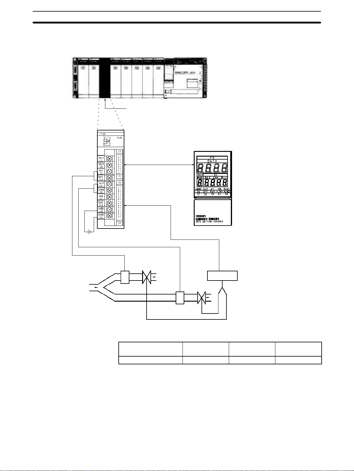
1-2 Basic System Configuration
SYSMAC C200H/C200HS PC
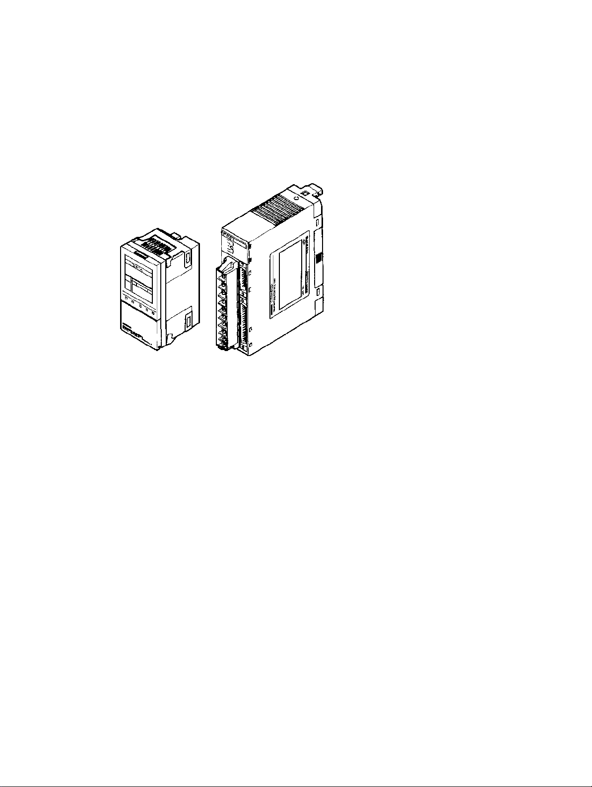
C200H-PID0j
PID Control Unit
Connecting cables:
C200H-CN225 (2 m)
C200H-CN425 (4 m)
Recommended cable:
ES1000-CA021-051 (0.5 m)
ES1000-CA021-102 (1 m)
ES1000-CA021-202 (2 m)
Section 1-2
Data Setting Console
C200H-DSC01
24 VDC
Remote I/O Terminal or
Connector Terminal
Block Converter Unit
(Refer to page 15)
Relay box
Gas
Mixture
Loop 1 Loop 2
Air
Flow sensor
Valve
Flow sensor Valve
PID Control Unit Models
Output type Transistor
output
Model C200H-PID01 C200H-PID02 C200H-PID03
Voltage output Current output
Number of Units The PID Control Unit belongs to the C200H Special I/O Unit group. A maximum
of ten Special I/O Units (including PC Link Units) can be mounted on the CPU
Rack, Expansion I/O Rack, and Slave Rack.
Note Configure the Units such that the maximum current supplied for each Rack is
greater than or equal to the total current consumption for the Units.
Refer to the
C200H PC Operation Manuals
for details on configuring systems.
Number of Units Mountable
on Slave Rack
The number of Special I/O Units used with a Slave Rack is limited by data transmission considerations, as shown in the table below. The numbers in the table
3

Basic System Configuration
Section 1-2
indicate the maximum number of Units of groups A, B, C, or D which can be used
with a single Slave Rack.
A B C D
High-speed Counter Units
Position Control Units
(NC111/112)
ASCII Unit
Analog I/O Units
ID Sensor Units
Fuzzy Logic Unit
4 units max. 8 units max. 6 units max. 2 units max.
High-density and Mixed I/O
Units
Temperature Control Units
Heat/Cool Temperature
Control Units
PID Control Units
Cam Positioner Unit
Temperature Sensor Units
Voice Unit
Position Control Unit
(NC211)
Note 1. When a combination of Units from groups A, B, C, and D is used, the number
from each group must satisfy both the following equations:
3A + B + 2C + 6D ≤ 12
A + B + C + D ≤ 8
2. Other Units can be added until the total number of units reaches ten. If PC
Link Units are used, the number of Units including the PC Link Units must
not exceed ten.
Precautions The IR area of the C200H Special I/O Unit is allocated according to the setting of
not
the unit number switch on the front panel,
unit is mounted. Refer to
4-1 Memory Allocation
the address of the slot where the
for the allocation of the memory
area.
With the C200 H, leave the two slots next to the CPU free. It is not possible to use
devices connected to the CPU (such as the Programming Console) if these slots
are occupied.
If the C200H Slave Rack is connected to another SYSMAC model Remote I/O
Master Unit, such as the C120, C500, C1000H, or C2000H, it is not possible to
use a Special I/O Unit with the C200H Slave Rack.
WARNING Always turn the C200H power off before connecting or disconnecting a Unit,
Caution Connect thermocouples with the appropriate compensating conductor.
Additional Function
Description of Function
terminal block, or output connector.
Wire I/O leads in separate ducts from power leads to prevent noise problems.
The function described below has been added to products with the following lot
number and later ones.
07 Z 4 O
1994 (last digit of the year)
December (X: October, Y: November, Z: December)
07 (7th day of the month)
RAM Write Commands
• Previous commands allowed reading and writing to the EEPROM only. These
new commands allow writing to the RAM.
• When various settings require frequent rewriting, write to the RAM and, after
confirming the setting values, save the data by writing it to the EEPROM. The
data written to the RAM is deleted when the power is turned off.
4

Basic System Configuration
Section 1-2
• List of RAM Write Commands
Parameter Command Write Read
Set point 4 0 Yes No
Execution bank number 4 2 Yes No
Alarm SV 1 4 3 Yes No
Alarm SV 2 4 4 Yes No
Input shift value 4 5 Yes No
Proportional band 4 6 Yes No
Integral (reset) time 4 7 Yes No
Derivative (rate) time 4 8 Yes No
Decimal point position 5 2 Yes No
Scaling lower limit 5 3 Yes No
Scaling upper limit 5 4 Yes No
Control period 5 7 Yes No
Hysteresis 5 8 Yes No
Alarm hysteresis 5 9 Yes No
Digital filter 5 E Yes No
Alarm 1 mode 6 4 Yes No
Alarm 2 mode 6 5 Yes No
5

Connections and Settings
This section provides information on the connections and settings of the PID Control Unit.
2-1 Nomenclature 8 . . . . . . . . . . . . . . . . . . . . . . . . . . . . . . . . . . . . . . . . . . . . . . . . . . . . .
2-2 Switch Settings 8 . . . . . . . . . . . . . . . . . . . . . . . . . . . . . . . . . . . . . . . . . . . . . . . . . . . .
2-3 Wiring 12 . . . . . . . . . . . . . . . . . . . . . . . . . . . . . . . . . . . . . . . . . . . . . . . . . . . . . . . . . . .
2-3-1 Input Wiring 12 . . . . . . . . . . . . . . . . . . . . . . . . . . . . . . . . . . . . . . . . . . . . .
2-3-2 Output Wiring 13 . . . . . . . . . . . . . . . . . . . . . . . . . . . . . . . . . . . . . . . . . . . .
2-3-3 Data Setting Console Cables 16 . . . . . . . . . . . . . . . . . . . . . . . . . . . . . . . . .
SECTION 2
7
Switch Settings
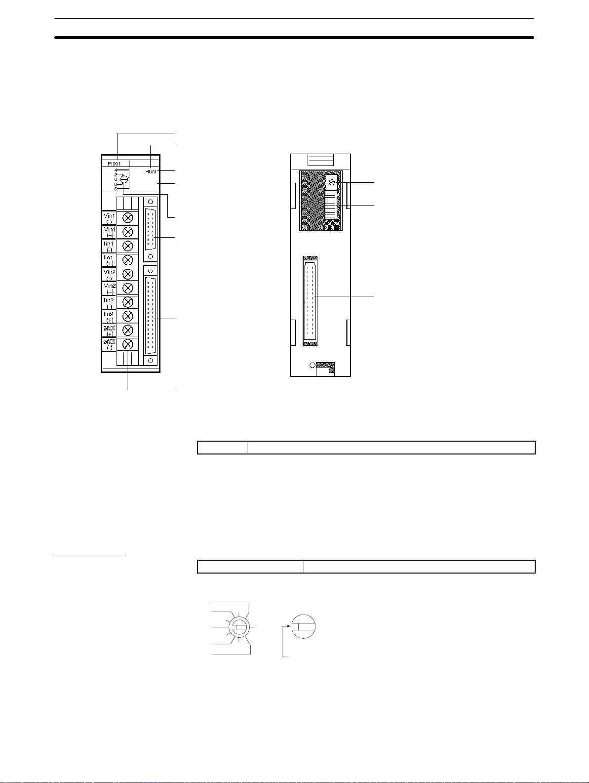
2-1 Nomenclature
C200H-PID0j
Section 2-2
Front Panel
Model label
Cover
RUN indicator
SW2
(Switching memory contents
and setting direction under
the cover)
SW1
(Unit number setting)
Data Setting Console
connector
Output connector
Input terminal block
Rear Panel
SW202
(Input type setting)
SW203
(Operation and function settings)
Rack connector
Indicators
RUN Lit when the PID Control Unit is operating normally.
2-2 Switch Settings
The function and setting of switches are identical for all models, except for
SW202.
Unit Number
SW1 Unit number setting
4
2
0
8
6
The addresses are allocated as shown in the following table according to the
Unit number setting.
(3)
(1)
(9)
(5)
(7)
The cut-out indicates the selected position. Negative numbers
are not indicated. Turn the switch with a flat-blade screwdriver.
Turn the switch until it clicks in position. Do not leave the switch
between two settings.
8
Switch Settings
Section 2-2
Unit no.
setting
0 Wd 100 to 109
1 Wd 1 10 to 119
2 Wd 120 to 129
3 Wd 130 to 139
4 Wd 140 to 149
5 Wd 150 to 159
6 Wd 160 to 169
7 Wd 170 to 179
8 Wd 180 to 189
9 Wd 190 to 199
Allocated address
The switch is factory-set to 0.
Note If the Unit number is set to an existing Unit number, an alarm occurs and the
C200H does not operate.
Turn the C200H power off before setting the Unit number. If the setting is
changed with the power on, the new setting is not valid until the power is turned
off and back on again.
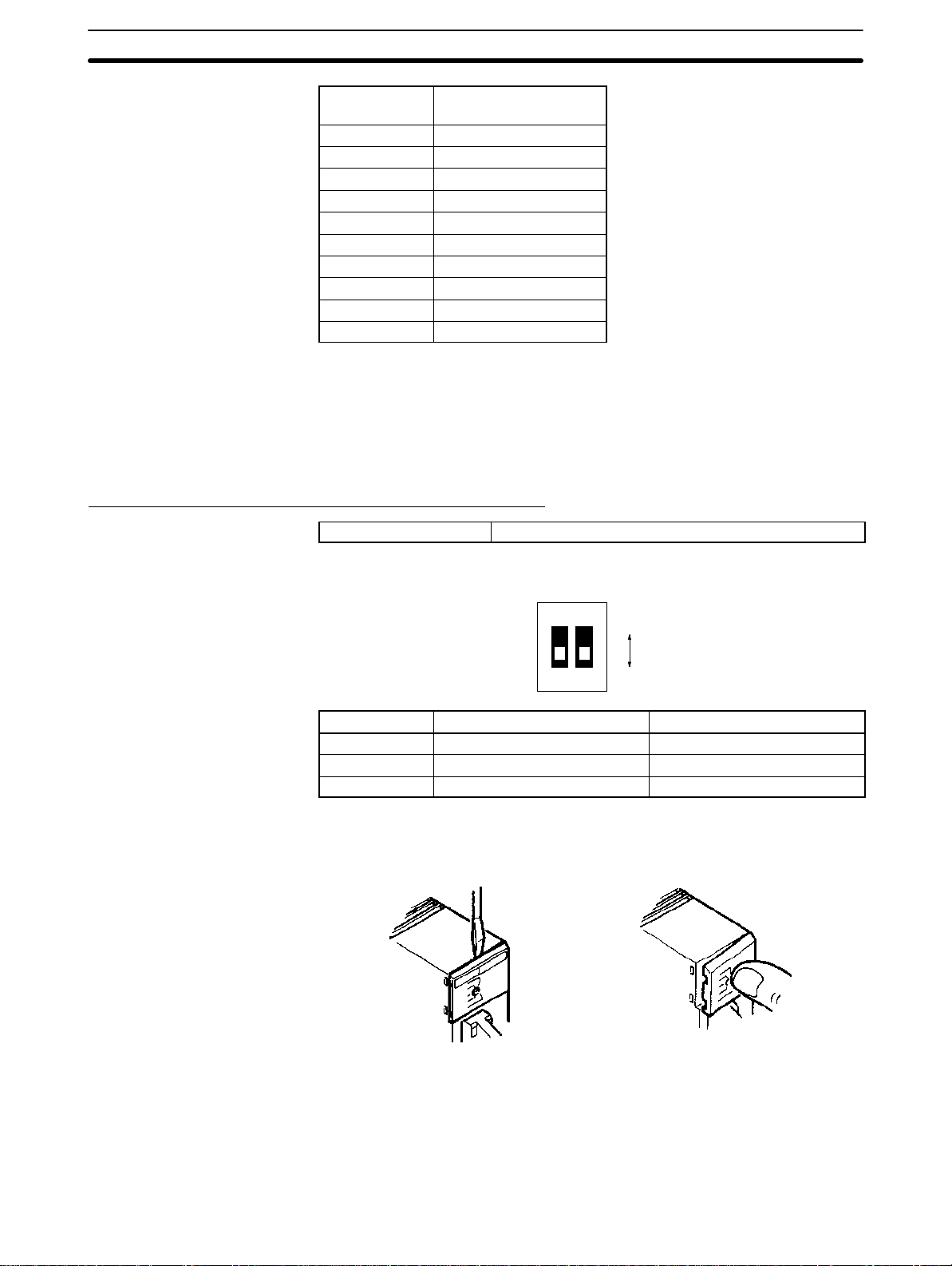
Switching Memory Contents and Setting Direction
SW2 Switching memory contents and setting direction
Remove the cover and set the switch with the tip of a ballpoint pen or similar object.
Switch no. Pin 1 Pin 2
Function Switching memory contents Setting direction
ON Normal C200H PC
OFF Fixed Data Setting Console
The new setting is valid immediately after the switch setting is changed.
Removing and Attaching the Cover
1
2
ON
OFF
Removing the Cover Attaching the Cover
OFF
Insert a small flat-blade screwdriver between the case and
the cover at the top of the Unit
and lever off the cover.
Place the right edge of the
cover against the case and
press into position.
Switching Memory Contents The contents of the allocated memory differ according to the Unit number set-
ting.
9
Switch Settings
Section 2-2
Normal Parameters can be designated as required using
Fixed Parameters are allocated in advance.
Refer to
4-1 Memory Allocation
commands (Refer to
for details of the memory contents.
4-1 Memory Allocation
).
Setting Direction Selects whether the data settings are made from the Data Setting Console or
from the C200H PC, using a user program or Programming Console.
Executed Bank Number
The setting of the executed bank number is made from the C200H PC, regardless of the ON/OFF setting of this switch.
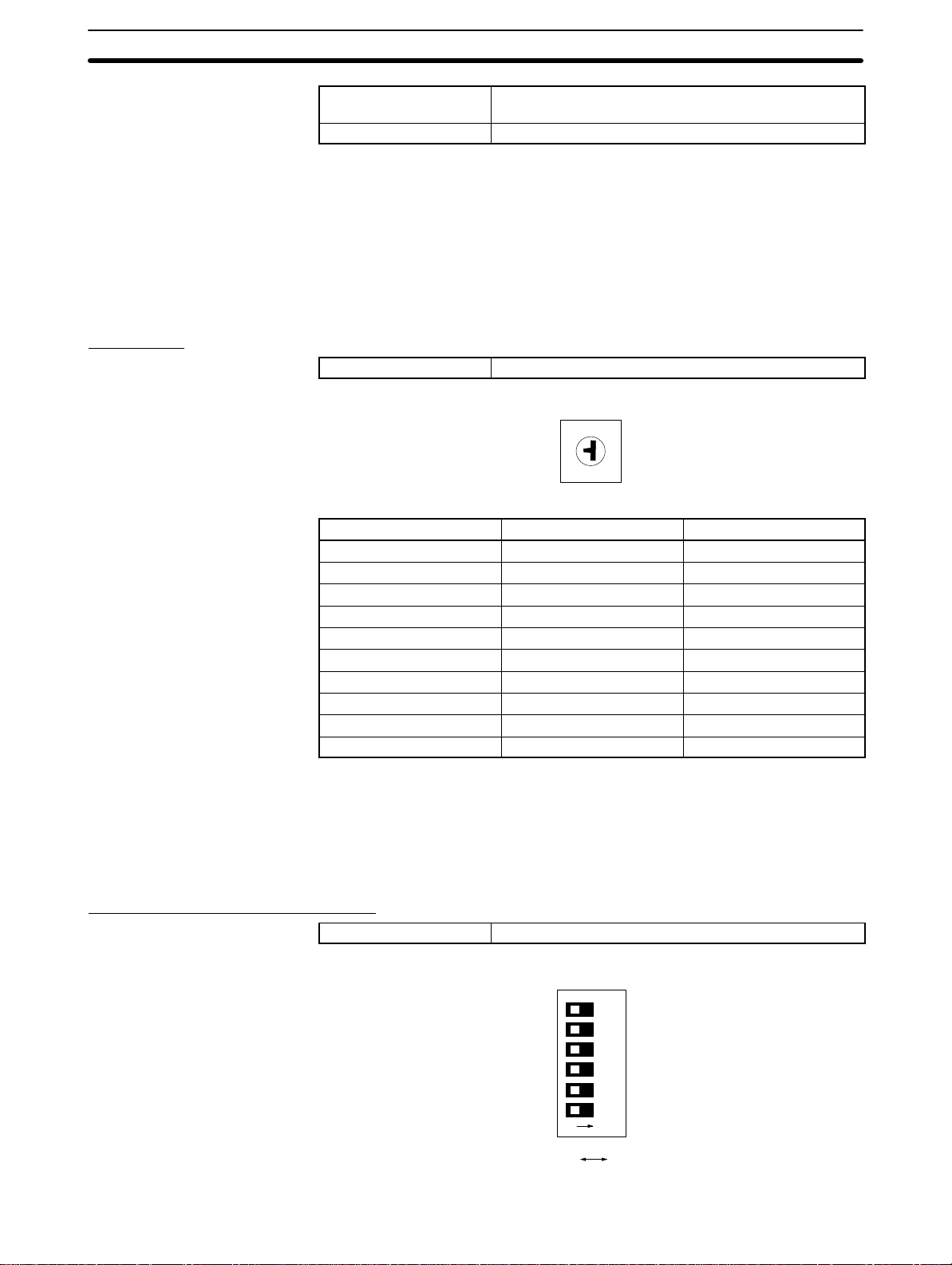
Input Type
SW202 Input type setting
3
2
4
1
0
5
9
6
7
8
Switch number Loop 1 Loop 2
0 4 to 20 mA 4 to 20 mA
1 1 to 5 V 1 to 5 V
2 0 to 5 V 0 to 5 V
3 0 to 10 V 0 to 10 V
4 4 to 20 mA 1 to 5 V
5 4 to 20 mA 0 to 5 V
6 4 to 20 mA 0 to 10 V
7 1 to 5 V 0 to 5 V
8 1 to 5 V 0 to 10 V
9 0 to 5 V 0 to 10 V
The switch is factory-set to 0.
The selected position is shown by the arrow. Turn the switch with a small flat-
blade screwdriver.
The permissible setting range for measurement is –999 to 9999 (EU).
Operation and Function Setting
SW203 Operation and Function Setting
10
134562
NO
OFF ON

Switch Settings
Pin no. Function OFF ON
6 Loop 2
Input approximation
5 Loop 1
Input approximation
4 Loop 2 Enabled Disabled or not used
3 SP write mode EEPROM and RAM RAM
2 Control action Reverse Normal
1 Control method PID control ON/OFF control
Straight line Square root
Straight line Square root
Section 2-2
approximation
approximation
The switch is factory-set to OFF.
Input Approximation Set each loop to either straight line (no approximation) or square root approxi-
mation.
Loop 2 Set to “enabled” to use input loop 2, or to “disabled” to use only input loop 1. It is
not possible to use only input loop 2.
Note Always set this switch to the ON (disabled) position when input loop 2 is not
used. A sensor error occurs if this switch is set to the OFF (enabled) position
when no temperature sensor is connected to loop 2.
SP Write Mode This setting selects the SP storage memory. Set it to ON or use RAM Write com-
mands if the writing is to be frequently changed.
Display Units Selects whether setting and SVs displayed on the Data Setting Console are in
Celsius or Fahrenheit.
Control Action Reverse:
The output is increased when the measured temperature is below the SP (i.e., a
negative temperature difference).
Normal:
The output is increased when the measured temperature is above the SP (i.e., a
positive temperature difference).
Control Method Selects the method of control.
11
Wiring
2-3 Wiring
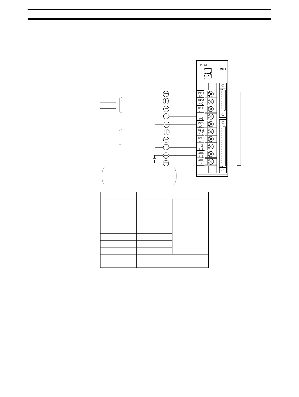
2-3-1 Input Wiring
C200H-PID0j
Section 2-3
Voltage input
Loop 1
Current input
Voltage input
Loop 2
Current input
24 VDC
0.2 A
The 24-VDC output from the C200H
CPU or the Power Supply Units is
convenient.
Terminal no. T erminal name
A0 Vin (–) Loop 1
A1 Vin (+)
A2 lin (–)
A3 lin (+)
A4 Vin (–) Loop 2
A5 Vin (+)
A6 lin (–)
A7 lin (+)
A8 24 VDC
A9 GND
A0
A1
A2
A3
A4
A5
A6
A7
A8
A9
Refer to the
table below.
Input Wiring Precautions
1, 2, 3...
12
1. The PID Control Unit will not operate correctly if the SW202 setting does not
match the type of inputs that are connected. In addition, each loop can be
connected to either voltage inputs or current inputs, but not to both. For example, if Loop 1 is set for voltage input, then current input will not work.
2. If no input lead is connected to Loop 2, turn SW203-4 on the rear of the Unit
ON to disable Loop 2. A sensor error occurs if this switch is set to the OFF
(enabled) position when no sensor is connected to Loop 2.
3. Be sure to wire the polarity correctly for each input.
4. Wire I/O leads in separate ducts from power leads to prevent noise problems.
5. A voltage of 24 VDC is used for the voltage output, current output and Data
Setting Console power supply.
6. The terminal block is removable. Make sure that it is attached correctly after
the input wiring connections are completed.
 Loading...