

Omron SYSMAC C200H-NC112 Operation Manual
Cat. No. W128-E1-4
SYSMAC
C200H-NC112
Position Control Unit
C200H-NC112 Position Control Unit
Operation Manual
September 2000

Notice:
OMRON products are manufactured for use according to proper procedures by a qualified operator
and only for the purposes described in this manual.
The following conventions are used to indicate and classify precautions in this manual. Always heed
the information provided with them. Failure to heed precautions can result in injury to people or damage to property.
DANGER Indicates an imminently hazardous situation which, if not avoided, will result in death or
!
serious injury.
WARNING Indicates a potentially hazardous situation which, if not avoided, could result in death or
!
serious injury.
Caution Indicates a potentially hazardous situation which, if not avoided, may result in minor or
!
moderate injury, or property damage.
OMRON Product References
All OMRON products are capitalized in this manual. The word “Unit” is also capitalized when it refers
to an OMRON product, regardless of whether or not it appears in the proper name of the product.
The abbreviation “Ch,” which appears in some displays and on some OMRON products, often means
“word” and is abbreviated “Wd” in documentation in this sense.
The abbreviation “PC” means Programmable Controller and is not used as an abbreviation for anything else.
Visual Aids
The following headings appear in the left column of the manual to help you locate different types of
information.
OMRON, 1990
All rights reserved. No part of this publication may be reproduced, stored in a retrieval system, or transmitted, in any
form, or by any means, mechanical, electronic, photocopying, recording, or otherwise, without the prior written permission of OMRON.
No patent liability is assumed with respect to the use of the information contained herein. Moreover, because OMRON is
constantly striving to improve its high-quality products, the information contained in this manual is subject to change
without notice. Every precaution has been taken in the preparation of this manual. Nevertheless, OMRON assumes no
responsibility for errors or omissions. Neither is any liability assumed for damages resulting from the use of the information contained in this publication.
Note Indicates information of particular interest for efficient and convenient operation
of the product.
Reference Indicates supplementary information on related topics that may be of interest to
the user.
1, 2, 3...
1. Indicates lists of one sort or another, such as procedures, checklists, etc.
ii

About this Manual:
The OMRON C200H-NC112 Position Control Unit is a Special I/O Unit for C200H PCs. It is designed
to control positioning actions through pulse train outputs to a motor driver, based on PC programming
and external control inputs.
This manual covers the specifications and procedures necessary for operation and installation. Before
attempting to operate the C200H Position Control Unit, be sure to thoroughly familiarize yourself with
the information contained herein.
During operation, refer to the C200H PC Operation Manual as necessary for programming and system details. Note that the term “channel” employed in the C200H PC Operation Manual (and other
earlier manuals) has been replaced by the term “word” in this manual, where it refers to a 16-bit address. Wherever the term “channel” (either written in full or abbreviated as “ch”) continues to appear,
whether in earlier manuals, on displays, or on the Units themselves, it can be taken to have the same
meaning as “word.”
Section 1
well as the basic configuration and principles of positioning control systems. Reading this section first
will give you a familiarity with the essential terminology used in this manual and an understanding of
the fundamentals necessary for successful operation.
Section 2
Section 3
Position Control Unit operation other than commands.
Section 4
Section 5
Section 6
Unit operation.
The appendices contain lists of error and alarm codes, DM and IR area data allocation charts, specifi-
cations, and a table of standard models. There are also an index and a glossary of terms at the back
of the manual.
describes the basic features, components, and operation of the Position Control Unit, as
covers procedures such as wiring and switch setting which are necessary before operation.
explains data format and configuration, basic operating procedure, and various aspects of
covers commands and the data settings which are necessary for their execution.
provides examples of possible applications of PCU commands, inputs, and outputs.
outlines the procedures for handling errors and alarms that occur during Position Control
!
WARNING Failure to read and understand the information provided in this manual may result in
personal injury or death, damage to the product, or product failure. Please read each
section in its entirety and be sure you understand the information provided in the section
and related sections before attempting any of the procedures or operations given.
iii

TABLE OF CONTENTS
PRECAUTIONS vii . . . . . . . . . . . . . . . . . . . . . . . . . . . . . . . . . . . . . . . . . . . . . . . .
1 Intended Audience viii . . . . . . . . . . . . . . . . . . . . . . . . . . . . . . . . . . . . . . . . . . . . . . . .
2 General Precautions viii . . . . . . . . . . . . . . . . . . . . . . . . . . . . . . . . . . . . . . . . . . . . . . .
3 Safety Precautions viii . . . . . . . . . . . . . . . . . . . . . . . . . . . . . . . . . . . . . . . . . . . . . . . .
4 Operating Environment Precautions viii . . . . . . . . . . . . . . . . . . . . . . . . . . . . . . . . . . .
5 Application Precautions ix . . . . . . . . . . . . . . . . . . . . . . . . . . . . . . . . . . . . . . . . . . . .
SECTION 1 – Introduction 1 . . . . . . . . . . . . . . . . . . . . . . . . . . . . . . . . . . . . . . .
1–1 Features 2 . . . . . . . . . . . . . . . . . . . . . . . . . . . . . . . . . . . . . . . . . . . . . . . . . . . . . . . . .
1–2 Components 3 . . . . . . . . . . . . . . . . . . . . . . . . . . . . . . . . . . . . . . . . . . . . . . . . . . . . .
1–3 Basic Operating Principles 3 . . . . . . . . . . . . . . . . . . . . . . . . . . . . . . . . . . . . . . . . . .
1–4 I/O Configuration 4 . . . . . . . . . . . . . . . . . . . . . . . . . . . . . . . . . . . . . . . . . . . . . . . . .
1–5 Positioning System Principles 5 . . . . . . . . . . . . . . . . . . . . . . . . . . . . . . . . . . . . . . .
1–5–1 Open-loop System 7 . . . . . . . . . . . . . . . . . . . . . . . . . . . . . . . . . . . . . . . .
1–5–2 Semiclosed-loop System 8 . . . . . . . . . . . . . . . . . . . . . . . . . . . . . . . . . . .
SECTION 2 – Before Operation 11 . . . . . . . . . . . . . . . . . . . . . . . . . . . . . . . . . . .
2–1 Switch Settings 12 . . . . . . . . . . . . . . . . . . . . . . . . . . . . . . . . . . . . . . . . . . . . . . . . . . .
2–1–1 Switch Setting Examples 17 . . . . . . . . . . . . . . . . . . . . . . . . . . . . . . . . . . .
2–2 Wiring 21 . . . . . . . . . . . . . . . . . . . . . . . . . . . . . . . . . . . . . . . . . . . . . . . . . . . . . . . . . .
2–2–1 Input Connection Examples 27 . . . . . . . . . . . . . . . . . . . . . . . . . . . . . . . . .
2–2–2 Output Connection Examples 29 . . . . . . . . . . . . . . . . . . . . . . . . . . . . . . .
2–2–3 Wiring Precautions 38 . . . . . . . . . . . . . . . . . . . . . . . . . . . . . . . . . . . . . . . .
2–3 Dimensions 39 . . . . . . . . . . . . . . . . . . . . . . . . . . . . . . . . . . . . . . . . . . . . . . . . . . . . . .
SECTION 3 – Operation 41 . . . . . . . . . . . . . . . . . . . . . . . . . . . . . . . . . . . . . . . . .
3–1 Operational Flow 42 . . . . . . . . . . . . . . . . . . . . . . . . . . . . . . . . . . . . . . . . . . . . . . . . .
3–2 Output Pulses 44 . . . . . . . . . . . . . . . . . . . . . . . . . . . . . . . . . . . . . . . . . . . . . . . . . . . .
3–3 Writing Data 44 . . . . . . . . . . . . . . . . . . . . . . . . . . . . . . . . . . . . . . . . . . . . . . . . . . . . .
3–4 Data Configuration and Allocation 45 . . . . . . . . . . . . . . . . . . . . . . . . . . . . . . . . . . .
3–5 DM Area Data Format 48 . . . . . . . . . . . . . . . . . . . . . . . . . . . . . . . . . . . . . . . . . . . . .
3–6 Flags and Other Input Data 48 . . . . . . . . . . . . . . . . . . . . . . . . . . . . . . . . . . . . . . . . . .
3–7 DM Area Allocation 48 . . . . . . . . . . . . . . . . . . . . . . . . . . . . . . . . . . . . . . . . . . . . . . .
3–7–1 Zones 50 . . . . . . . . . . . . . . . . . . . . . . . . . . . . . . . . . . . . . . . . . . . . . . . . . .
3–7–2 Backlash Compensation 52 . . . . . . . . . . . . . . . . . . . . . . . . . . . . . . . . . . . .
3–7–3 Internal CW/CCW Limits 53 . . . . . . . . . . . . . . . . . . . . . . . . . . . . . . . . . .
3–7–4 Data Calculations 53 . . . . . . . . . . . . . . . . . . . . . . . . . . . . . . . . . . . . . . . . .
SECTION 4 – Commands 59 . . . . . . . . . . . . . . . . . . . . . . . . . . . . . . . . . . . . . . . .
4–1 START 60 . . . . . . . . . . . . . . . . . . . . . . . . . . . . . . . . . . . . . . . . . . . . . . . . . . . . . . . . .
4–1–1 DM Area Settings 60 . . . . . . . . . . . . . . . . . . . . . . . . . . . . . . . . . . . . . . . .
4–2 Positioning Actions 61 . . . . . . . . . . . . . . . . . . . . . . . . . . . . . . . . . . . . . . . . . . . . . . . .
4–2–1 IR Area Settings 66 . . . . . . . . . . . . . . . . . . . . . . . . . . . . . . . . . . . . . . . . . .
4–2–2 Execution Examples 68 . . . . . . . . . . . . . . . . . . . . . . . . . . . . . . . . . . . . . .
4–3 ORIGIN SEARCH 71 . . . . . . . . . . . . . . . . . . . . . . . . . . . . . . . . . . . . . . . . . . . . . . . .
4–3–1 DM Area Settings 71 . . . . . . . . . . . . . . . . . . . . . . . . . . . . . . . . . . . . . . . .
4–3–2 IR Area Settings 72 . . . . . . . . . . . . . . . . . . . . . . . . . . . . . . . . . . . . . . . . . .
4–3–3 Execution Examples 73 . . . . . . . . . . . . . . . . . . . . . . . . . . . . . . . . . . . . . .
4–3–4 Completion Examples 84 . . . . . . . . . . . . . . . . . . . . . . . . . . . . . . . . . . . . .
4–4 ORIGIN RETURN 86 . . . . . . . . . . . . . . . . . . . . . . . . . . . . . . . . . . . . . . . . . . . . . . . .
4–4–1 DM Area Settings 87 . . . . . . . . . . . . . . . . . . . . . . . . . . . . . . . . . . . . . . . .
4–4–2 IR Area Settings 87 . . . . . . . . . . . . . . . . . . . . . . . . . . . . . . . . . . . . . . . . . .
4–4–3 Execution Example 87 . . . . . . . . . . . . . . . . . . . . . . . . . . . . . . . . . . . . . . .
v

Table of contents
4–5 RELEASE PROHIBIT 89 . . . . . . . . . . . . . . . . . . . . . . . . . . . . . . . . . . . . . . . . . . . . .
4–6 READ ERROR 91 . . . . . . . . . . . . . . . . . . . . . . . . . . . . . . . . . . . . . . . . . . . . . . . . . . .
4–6–1 Execution Example 92 . . . . . . . . . . . . . . . . . . . . . . . . . . . . . . . . . . . . . . .
4–6–2 Reading from the Programming Console 92 . . . . . . . . . . . . . . . . . . . . . .
4–7 RESET ORIGIN 93 . . . . . . . . . . . . . . . . . . . . . . . . . . . . . . . . . . . . . . . . . . . . . . . . . .
4–8 TEACH 93 . . . . . . . . . . . . . . . . . . . . . . . . . . . . . . . . . . . . . . . . . . . . . . . . . . . . . . . . .
4–8–1 IR Area Settings 94 . . . . . . . . . . . . . . . . . . . . . . . . . . . . . . . . . . . . . . . . . .
4–8–2 Execution Example 94 . . . . . . . . . . . . . . . . . . . . . . . . . . . . . . . . . . . . . . .
4–8–3 Teaching From the Programming Console 94 . . . . . . . . . . . . . . . . . . . . .
4–9 TRANSFER DATA 95 . . . . . . . . . . . . . . . . . . . . . . . . . . . . . . . . . . . . . . . . . . . . . . . .
4–9–1 Normal Transfer 96 . . . . . . . . . . . . . . . . . . . . . . . . . . . . . . . . . . . . . . . . . .
4–9–2 IR Area Settings 97 . . . . . . . . . . . . . . . . . . . . . . . . . . . . . . . . . . . . . . . . . .
4–9–3 Present Position Preset 99 . . . . . . . . . . . . . . . . . . . . . . . . . . . . . . . . . . . . .
4–10 Manual Operations 102 . . . . . . . . . . . . . . . . . . . . . . . . . . . . . . . . . . . . . . . . . . . . . . . .
4–10–1 DM Area Settings 102 . . . . . . . . . . . . . . . . . . . . . . . . . . . . . . . . . . . . . . . .
4–10–2 IR Area Settings 103 . . . . . . . . . . . . . . . . . . . . . . . . . . . . . . . . . . . . . . . . . .
4–10–3 HIGH-SPEED JOG 103 . . . . . . . . . . . . . . . . . . . . . . . . . . . . . . . . . . . . . . .
4–10–4 LOW-SPEED JOG 104 . . . . . . . . . . . . . . . . . . . . . . . . . . . . . . . . . . . . . . . .
4–10–5 INCH 104 . . . . . . . . . . . . . . . . . . . . . . . . . . . . . . . . . . . . . . . . . . . . . . . . . .
4–11 External Interrupt Commands 105 . . . . . . . . . . . . . . . . . . . . . . . . . . . . . . . . . . . . . . .
4–11–1 STOP 107 . . . . . . . . . . . . . . . . . . . . . . . . . . . . . . . . . . . . . . . . . . . . . . . . . .
4–11–2 CHANGE SPEED 115 . . . . . . . . . . . . . . . . . . . . . . . . . . . . . . . . . . . . . . . .
SECTION 5 – Programming Examples 117 . . . . . . . . . . . . . . . . . . . . . . . . . . . . .
5–1 Operation with Minimum Data (Displaying JOG Positions) 118 . . . . . . . . . . . . . . . .
5–2 Positioning at Intervals Using RESET ORIGIN 119 . . . . . . . . . . . . . . . . . . . . . . . . .
5–3 Feeding Selectively with START 121 . . . . . . . . . . . . . . . . . . . . . . . . . . . . . . . . . . . . .
5–4 TRANSFER DATA from Other PC Areas 123 . . . . . . . . . . . . . . . . . . . . . . . . . . . . . .
5–5 TRANSFER DATA from External Switches 125 . . . . . . . . . . . . . . . . . . . . . . . . . . . .
5–6 Using START to Carry Out Positioning Actions 128 . . . . . . . . . . . . . . . . . . . . . . . . .
5–7 Using Origin and Origin Proximity Signals 132 . . . . . . . . . . . . . . . . . . . . . . . . . . . . .
5–8 Using Zones to Control Jogging 132 . . . . . . . . . . . . . . . . . . . . . . . . . . . . . . . . . . . . . .
5–9 Setting Speeds 134 . . . . . . . . . . . . . . . . . . . . . . . . . . . . . . . . . . . . . . . . . . . . . . . . . . . .
5–10 Using a Multiple Bank Program 134 . . . . . . . . . . . . . . . . . . . . . . . . . . . . . . . . . . . . . .
SECTION 6 – Error Processing 137 . . . . . . . . . . . . . . . . . . . . . . . . . . . . . . . . . . .
6–1 Alarms and Errors 138 . . . . . . . . . . . . . . . . . . . . . . . . . . . . . . . . . . . . . . . . . . . . . . . . .
6–2 Outputs to the IR Area 138 . . . . . . . . . . . . . . . . . . . . . . . . . . . . . . . . . . . . . . . . . . . . .
6–3 Alarm/Error Indicators 138 . . . . . . . . . . . . . . . . . . . . . . . . . . . . . . . . . . . . . . . . . . . . .
6–4 Error Code Output 138 . . . . . . . . . . . . . . . . . . . . . . . . . . . . . . . . . . . . . . . . . . . . . . . .
6–5 Troubleshooting from the PC 140 . . . . . . . . . . . . . . . . . . . . . . . . . . . . . . . . . . . . . . . .
6–5–1 Error List for Special I/O Units 140 . . . . . . . . . . . . . . . . . . . . . . . . . . . . . .
6–5–2 AR Area Error and Restart Bits for Special I/O Units 140 . . . . . . . . . . . .
6–6 Basic Troubleshooting Chart 141 . . . . . . . . . . . . . . . . . . . . . . . . . . . . . . . . . . . . . . . .
6–7 Detection of Abnormal Pulse Outputs 143 . . . . . . . . . . . . . . . . . . . . . . . . . . . . . . . . .
Appendix 145 . . . . . . . . . . . . . . . . . . . . . . . . . . . . . . . . . . . . . . . . . . . . . . . . . . . . . .
A – Standard Models 145 . . . . . . . . . . . . . . . . . . . . . . . . . . . . . . . . . . . . . . . . . . . . . . . . . . . .
B – Specifications 147 . . . . . . . . . . . . . . . . . . . . . . . . . . . . . . . . . . . . . . . . . . . . . . . . . . . . . .
C – DM Area Allocations 149 . . . . . . . . . . . . . . . . . . . . . . . . . . . . . . . . . . . . . . . . . . . . . . . .
E – Alarm Code List 159 . . . . . . . . . . . . . . . . . . . . . . . . . . . . . . . . . . . . . . . . . . . . . . . . . . . .
F – Error Code List 161 . . . . . . . . . . . . . . . . . . . . . . . . . . . . . . . . . . . . . . . . . . . . . . . . . . . . .
G – Using the C200H-NC112 with CS1-series PCs 165 . . . . . . . . . . . . . . . . . . . . . . . . . . . .
vi
Glossary 173 . . . . . . . . . . . . . . . . . . . . . . . . . . . . . . . . . . . . . . . . . . . . . . . . . . . . . . .
Index 179 . . . . . . . . . . . . . . . . . . . . . . . . . . . . . . . . . . . . . . . . . . . . . . . . . . . . . . . . .

PRECAUTIONS
This section provides general precautions for using the Programmable Controller (PC) and related devices.
The information contained in this section is important for the safe and reliable application of the Programmable Controller. You must read this section and understand the information contained before attempting to set up or operate a
PC system.
1 Intended Audience viii . . . . . . . . . . . . . . . . . . . . . . . . . . . . . . . . . . . . . . . . . . . . . . . . .
2 General Precautions viii . . . . . . . . . . . . . . . . . . . . . . . . . . . . . . . . . . . . . . . . . . . . . . . .
3 Safety Precautions viii . . . . . . . . . . . . . . . . . . . . . . . . . . . . . . . . . . . . . . . . . . . . . . . . .
4 Operating Environment Precautions viii . . . . . . . . . . . . . . . . . . . . . . . . . . . . . . . . . . .
5 Application Precautions ix . . . . . . . . . . . . . . . . . . . . . . . . . . . . . . . . . . . . . . . . . . . . .
vii

1 Intended Audience
This manual is intended for the following personnel, who must also have knowledge of electrical systems (an electrical engineer or the equivalent).
• Personnel in charge of installing FA systems.
• Personnel in charge of designing FA systems.
• Personnel in charge of managing FA systems and facilities.
2 General Precautions
The user must operate the product according to the performance specifications
described in the relevant manuals.
Before using the product under conditions which are not described in the manual
or applying the product to nuclear control systems, railroad systems, aviation
systems, vehicles, combustion systems, medical equipment, amusement machines, safety equipment, and other systems, machines, and equipment that
may have a serious influence on lives and property if used improperly, consult
your OMRON representative.
Make sure that the ratings and performance characteristics of the product are
sufficient for the systems, machines, and equipment, and be sure to provide the
systems, machines, and equipment with double safety mechanisms.
This manual provides information for programming and operating the Unit. Be
sure to read this manual before attempting to use the Unit and keep this manual
close at hand for reference during operation.
4Operating Environment Precautions
WARNING It is extremely important that a PC and all PC Units be used for the specified
!
purpose and under the specified conditions, especially in applications that can
directly or indirectly affect human life. You must consult with your OMRON
representative before applying a PC system to the above-mentioned
applications.
3 Safety Precautions
WARNING Do not attempt to take any Unit apart while the power is being supplied. Doing so
!
may result in electric shock.
WARNING Do not touch any of the terminals or terminal blocks while the power is being
!
supplied. Doing so may result in electric shock.
WARNING Do not attempt to disassemble, repair, or modify any Units. Any attempt to do so
!
may result in malfunction, fire, or electric shock.
Caution Confirm safety at the destination node before transferring a program to another
!
node or changing contents of the I/O memory area. Doing either of these without
confirming safety may result in injury.
4 Operating Environment Precautions
viii
Caution Do not operate the control system in the following locations:
!
• Locations subject to direct sunlight.
• Locations subject to temperatures or humidity outside the range specified in
the specifications.
• Locations subject to condensation as the result of severe changes in temperature.

• Locations subject to corrosive or flammable gases.
• Locations subject to dust (especially iron dust) or salts.
• Locations subject to exposure to water, oil, or chemicals.
• Locations subject to shock or vibration.
Caution Take appropriate and sufficient countermeasures when installing systems in the
!
following locations:
• Locations subject to static electricity or other forms of noise.
• Locations subject to strong electromagnetic fields.
• Locations subject to possible exposure to radioactivity.
• Locations close to power supplies.
Caution The operating environment of the PC system can have a large effect on the lon-
!
gevity and reliability of the system. Improper operating environments can lead to
malfunction, failure, and other unforeseeable problems with the PC system. Be
sure that the operating environment is within the specified conditions at installation and remains within the specified conditions during the life of the system.
5 Application Precautions
Observe the following precautions when using the PC system.
5Application Precautions
WARNING Always heed these precautions. Failure to abide by the following precautions
!
could lead to serious or possibly fatal injury.
• Always ground the system to 100 Ω or less when installing the Units. Not con-
necting to a ground of 100 Ω or less may result in electric shock.
• Always turn OFF the power supply to the PC before attempting any of the following. Not turning OFF the power supply may result in malfunction or electric
shock.
• Mounting or dismounting Power Supply Units, I/O Units, CPU Units,
Memory Units, or any other Units.
• Assembling the Units.
• Setting DIP switches or rotary switches.
• Connecting cables or wiring the system.
• Connecting or disconnecting the connectors.
Caution Failure to abide by the following precautions could lead to faulty operation of the
!
PC or the system, or could damage the PC or PC Units. Always heed these precautions.
• Fail-safe measures must be taken by the customer to ensure safety in the
event of incorrect, missing, or abnormal signals caused by broken signal lines,
momentary power interruptions, or other causes.
• Interlock circuits, limit circuits, and similar safety measures in external circuits
(i.e., not in the Programmable Controller) must be provided by the customer.
• Always use the power supply voltages specified in this manual. An incorrect
voltage may result in malfunction or burning.
• Take appropriate measures to ensure that the specified power with the rated
voltage and frequency is supplied. Be particularly careful in places where the
power supply is unstable. An incorrect power supply may result in malfunction.
• Install external breakers and take other safety measures against short-circuiting in external wiring. Insufficient safety measures against short-circuiting may
result in burning.
ix

• Do not apply voltages to the Input Units in excess of the rated input voltage.
Excess voltages may result in burning.
• Do not apply voltages or connect loads to the Output Units in excess of the
maximum switching capacity. Excess voltage or loads may result in burning.
• Disconnect the functional ground terminal when performing withstand voltage
tests. Not disconnecting the functional ground terminal may result in burning.
• Be sure that all the mounting screws, terminal screws, and cable connector
screws are tightened to the torque specified in this manual. Incorrect tightening torque may result in malfunction.
• Leave the label attached to the Unit when wiring. Removing the label may result in malfunction if foreign matter enters the Unit.
• Remove the label after the completion of wiring to ensure proper heat dissipation. Leaving the label attached may result in malfunction.
• Double-check all wiring and switch settings before turning ON the power supply. Incorrect wiring may result in burning.
• Wire correctly. Incorrect wiring may result in burning.
• Mount Units only after checking terminal blocks and connectors completely.
• Be sure that the terminal blocks, Memory Units, expansion cables, and other
items with locking devices are properly locked into place. Improper locking
may result in malfunction.
• Check the user program for proper execution before actually running it on the
Unit. Not checking the program may result in an unexpected operation.
• Confirm that no adverse ef fect will occur in the system before attempting any of
the following. Not doing so may result in an unexpected operation.
• Changing the operating mode of the PC.
• Force-setting/force-resetting any bit in memory.
• Changing the present value of any word or any set value in memory.
• Resume operation only after transferring to the new CPU Unit the contents of
the DM Area, HR Area, and other data required for resuming operation. Not
doing so may result in an unexpected operation.
• Do not pull on the cables or bend the cables beyond their natural limit. Doing
either of these may break the cables.
• Do not place objects on top of the cables or other wiring lines. Doing so may
break the cables.
• Use crimp terminals for wiring. Do not connect bare stranded wires directly to
terminals. Connection of bare stranded wires may result in burning.
• When replacing parts, be sure to confirm that the rating of a new part is correct.
Not doing so may result in malfunction or burning.
• Before touching a Unit, be sure to first touch a grounded metallic object in order
to discharge any static built-up. Not doing so may result in malfunction or damage.
5Application Precautions
x

SECTION 1
Introduction
The C200H-NC112 Position Control Unit is a Special I/O Unit that outputs pulse trains to control a stepping motor driver
or a servomotor driver in accordance with a PC program or external inputs.
This section describes the basic features, components, and operation of the Position Control Unit, as well as the basic
configuration and principles of positioning control systems. Reading this section first will give you a familiarity with the
essential terminology used in this manual and an understanding of the fundamentals necessary for successful operation.
1–1 Features 2 . . . . . . . . . . . . . . . . . . . . . . . . . . . . . . . . . . . . . . . . . . . . . . . . . . . . . . . . .
1–2 Components 3 . . . . . . . . . . . . . . . . . . . . . . . . . . . . . . . . . . . . . . . . . . . . . . . . . . . . . .
1–3 Basic Operating Principles 3 . . . . . . . . . . . . . . . . . . . . . . . . . . . . . . . . . . . . . . . . . . .
1–4 I/O Configuration 4 . . . . . . . . . . . . . . . . . . . . . . . . . . . . . . . . . . . . . . . . . . . . . . . . . .
1–5 Positioning System Principles 5 . . . . . . . . . . . . . . . . . . . . . . . . . . . . . . . . . . . . . . . .
1–5–1 Open-loop System 7 . . . . . . . . . . . . . . . . . . . . . . . . . . . . . . . . . . . . . . . . .
1–5–2 Semiclosed-loop System 8 . . . . . . . . . . . . . . . . . . . . . . . . . . . . . . . . . . . .
1

Features Section 1–1
1–1 Features
Applicable Motor Drivers
Number of Control Axes
and Controlling Capacity
Manual Operation
Data Transfer
Establishing Position
Teaching
The pulse train output can be easily connected to either of the following devices:
1. Stepping motor driver
2. Servomotor driver designed for pulse train input
The Position Control Unit is designed to control a single axis and is capable
of controlling speeds and positions in accordance with data recorded in the
DM area of the C200H PC.
Three commands enable manual positioning control: HIGH-SPEED JOG,
LOW-SPEED JOG, and INCH.
PCU positioning actions, speeds, and other data can be stored in the DM
area or other areas of the PC and quickly transferred to the PCU via a
TRANSFER DATA command. This effectively increases the amount of
memory available to the PCU.
The TRANSFER DATA command can also be used to change the present
position to any desired value, including 0 (origin), any time the Position Control Unit is not outputting pulses.
The present position can be written into the memory of the PC as positioning
data whenever pulses are not being output.
Operation in Four Modes
Choice of Origin Detection
Method
Expanded Speed Range
Greater Switching Capacity
Optional Speed Numbers
Smoother Acceleration and
Deceleration
The C200H-NC112 Position Control Unit can be operated in any of four
modes, which are selected via the mode switch on the Unit. Mode 0 is equivalent to the C200H-NC111 Position Control Unit; the other three are for use
with servomotor drivers. Mode 3 is designed especially for use with the OMRON R88D-EP/SR (marketed in Japan) servomotor driver.
The method employed to detect the origin may be selected via the rear-panel
DIP switch.
The speed range has been expanded to enable settings anywhere from 1 to
250,000 pps (compared with 1 to 99,990 for the NC111). In addition, acceleration and deceleration speeds between 2 and 2,000 pps/ms are now possible (compared with 1 to 999 pps/ms for the NC111).
The minimum switching capacity has been increased from 2.5 mA (in the
NC111) to 7 mA at 5 VDC.
In the NC111, the speed number currently being executed is always incremented by one to obtain the subsequent target speed, but in the NC112, the
next speed number can be set in the DM area of the C200H PC. If desired,
speed numbers may be allowed to increment one by one as in the NC111.
Acceleration and deceleration have been made smoother by reducing each
incremental step from the NC111’s 10 ms to 4 ms.
More Completion Codes
2
In addition to the five completion codes possible with the NC111, the NC112
allows for a sixth, i.e., “extended with positioning”.
Basic Operating Principles Section 1–3
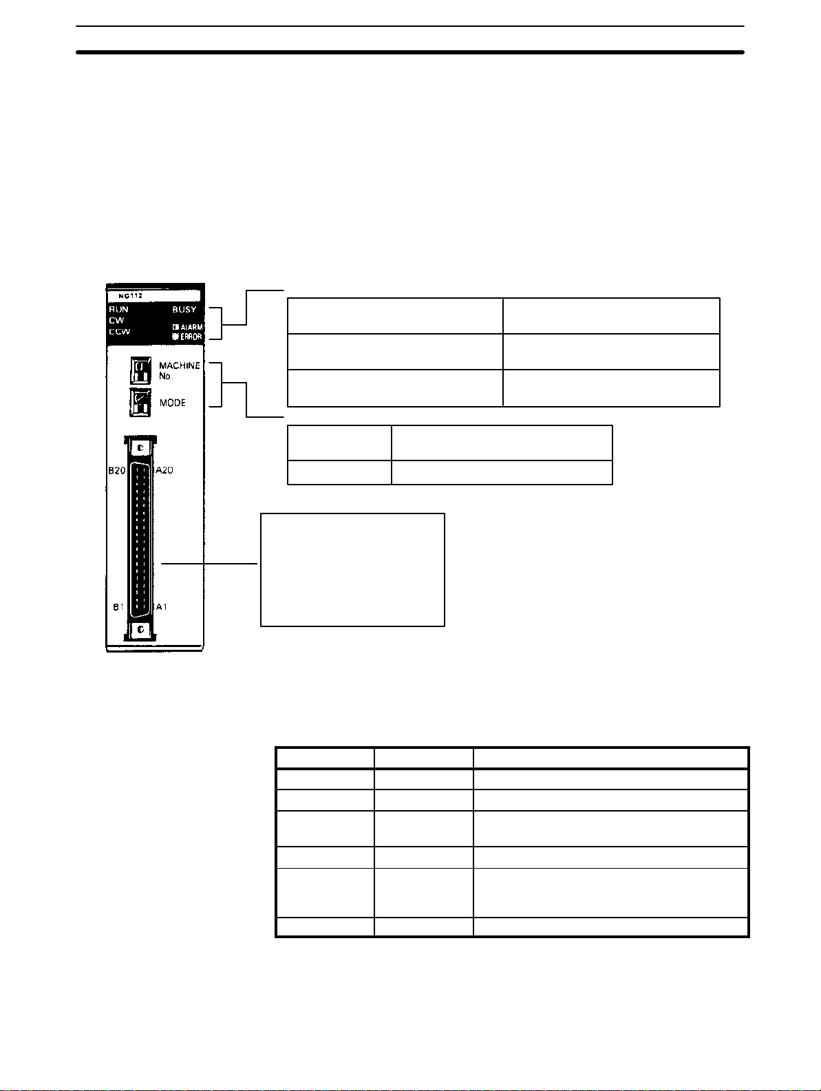
1–2 Components
In addition to the front-panel components described below, there is a DIP
switch located on the back panel. Pin settings for this switch, which are described in
Section 2–1
When setting the switches, use a screwdriver if necessary.
Do not apply excessive force to the switches.
Do not leave the switches halfway between two setting points or the Position
Control unit may malfunction.
Before operating these switches, make sure that power to the PC is off.
Indicators
RUN: indicates operation
is in progress
CW: indicates motor
is revolving clockwise
CCW: indicates motor
is revolving counterclockwise
Setting switches
MACHINE No.
MODE
, determine certain aspects of Unit operation.
BUSY: indicates operation/transfer
is in progress
ALARM: flashes when an abnormality has occurred
ERROR: lights when an error has occurred
Allocates a unit number (0 to 9) to
the Position Control Unit
Selects an operating mode (0 to 3).
Indicators
Connector
Used to connect the Position
Control Unit to a stepping motor driver or servomotor driver.
Attach the enclosed connector
to the proper cable.
Position Control Unit indicators (LEDs) are used to quickly determine operating status. They are particularly valuable in initial system activation and debugging, but can also be used to monitor Unit operation.
Indicator Color Function
RUN Green Lit during normal operation. Goes out on errors.
CW Green Lit during output of CW (clockwise) pulses.
CCW Green Lit during output of CCW (counterclockwise)
pulses.
BUSY Green Lit during positioning or data transfer.
ALARM
(flashing)
ERROR Red Lit when an error has caused operation to stop.
Red Flashing when a BCD error exists in initial data,
speed data, or positioning data updated with
TRANSFER DATA.
1–3 Basic Operating Principles
The basic operation of the C200H-NC112 Position Control Unit is fairly simple. It controls either a stepping motor or a servomotor in accordance with
3

I/O Configuration Section 1–4
data stored in the DM area of the PC. This data includes directions, speeds,
positions, and other information necessary for effective control. Before the
Position Control Unit can be operated, you must first input the essential data.
This is generally done via the Programming Console, although you can also
input data with the TEACH command.
The way in which the Position Control Unit makes use of this data is determined by the program in the PC. The program does not control all of the Position Control Unit’s operations directly, but rather, executes the Unit’s commands by turning command bits ON and OFF. The commands control such
functions as the starting and stopping of positioning, returning to the origin,
and so on. (The origin is simply the point which is designated as 0 at any given time.) Thus, while the Position Control Unit functions as an integral part of
your overall control system, it also exercises a good deal of autonomy. This
capability is essential to the concept of distributed control, whereby control of
each portion of an automated system is located near the devices actually
being controlled.
The fundamental unit of positioning is the positioning action. A particular positioning action moves the workpiece along the positioning axis in a direction,
at a speed, and to a position determined by the data which has previously
been set. The positioning action begins when the appropriate command bit
(START) is turned ON by the program.
A single positioning action may be executed by itself, or a bank of several
positioning actions may be executed in sequence. A particular bank of actions may be repeated again and again. Before beginning execution of positioning actions, it is necessary to define the origin as a reference point by, for
example, executing ORIGIN SEARCH.
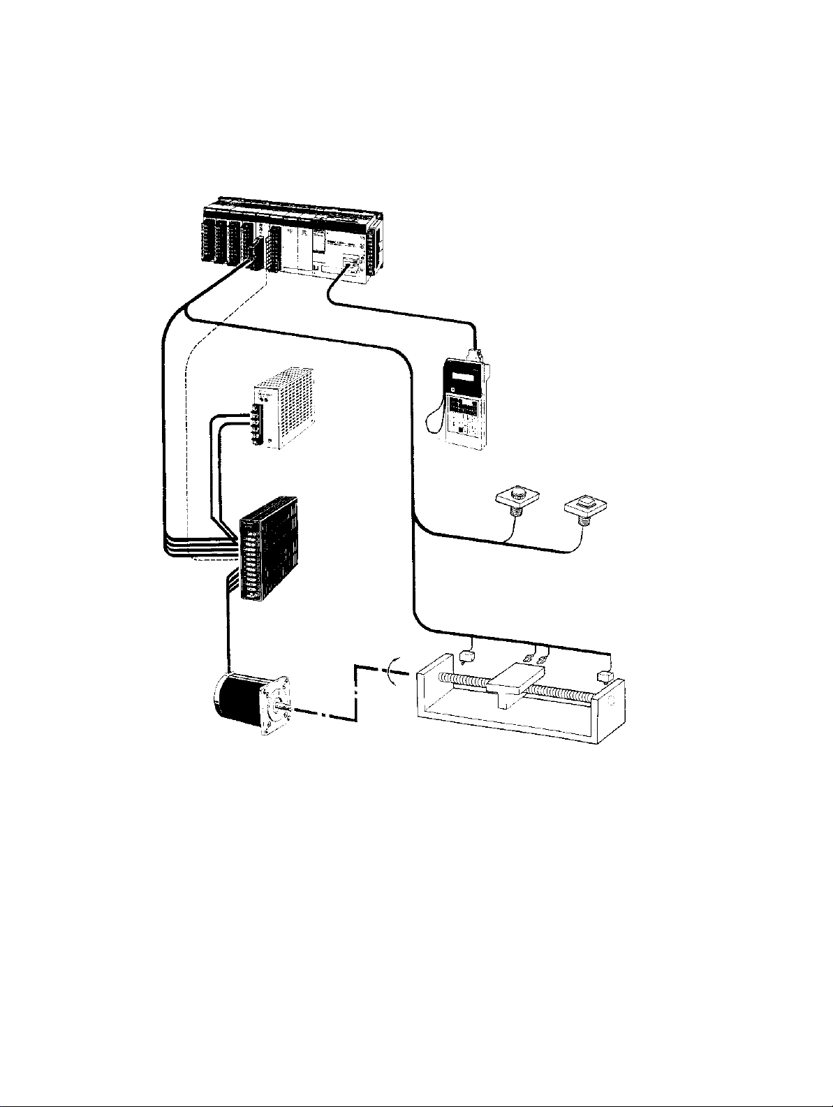
1–4 I/O Configuration
The basic I/O configuration is shown on the following page. Position Control
Unit outputs are connected to a motor driver, either for a stepping motor or
for a servomotor (AC or DC) capable of receiving pulse train inputs. The Unit
is controlled by inputs from devices and/or a control panel. It, in turn, outputs
pulse trains and direction signals to control the motor driver.
The motor driver controls either a stepping motor or a servomotor, depending
on whether you choose to employ an open-loop or semiclosed-loop system.
Section 1–5
(See
positioning device (such as a feed screw). An independent power supply
must be used for the motor driver. Some configurations also require an Input
Unit on a C200H Rack to control the motor driver.
Maximum Number of
Special I/O Units per PC
A maximum of 10 Special I/O Units, including Position Control Units,
High-Speed Counters, etc., can be mounted under the same PC, regardless
of whether they are on the CPU Rack, an Expansion I/O Rack, or a Slave
Rack. No more than four of these can be mounted onto any one Slave Rack.
Refer to the
). The stepping motor or servomotor controls some type of
Remote I/O System Operation Manuals
for further restrictions.
Mounting Location
Basic Configuration
4
The Position Control Unit can be mounted to any slot on any Rack except for
the two rightmost CPU Rack slots. Mounting the Unit to either of these slots
will prevent you from mounting devices directly to the CPU. The back-panel
DIP switch must be set before the Unit is mounted. This switch is inaccessible on a mounted Unit. (See
Although Unit operation can be indirectly controlled from a host computer,
Remote I/O Master Unit, or other control system or peripheral device, direct
Section 2–1
.)
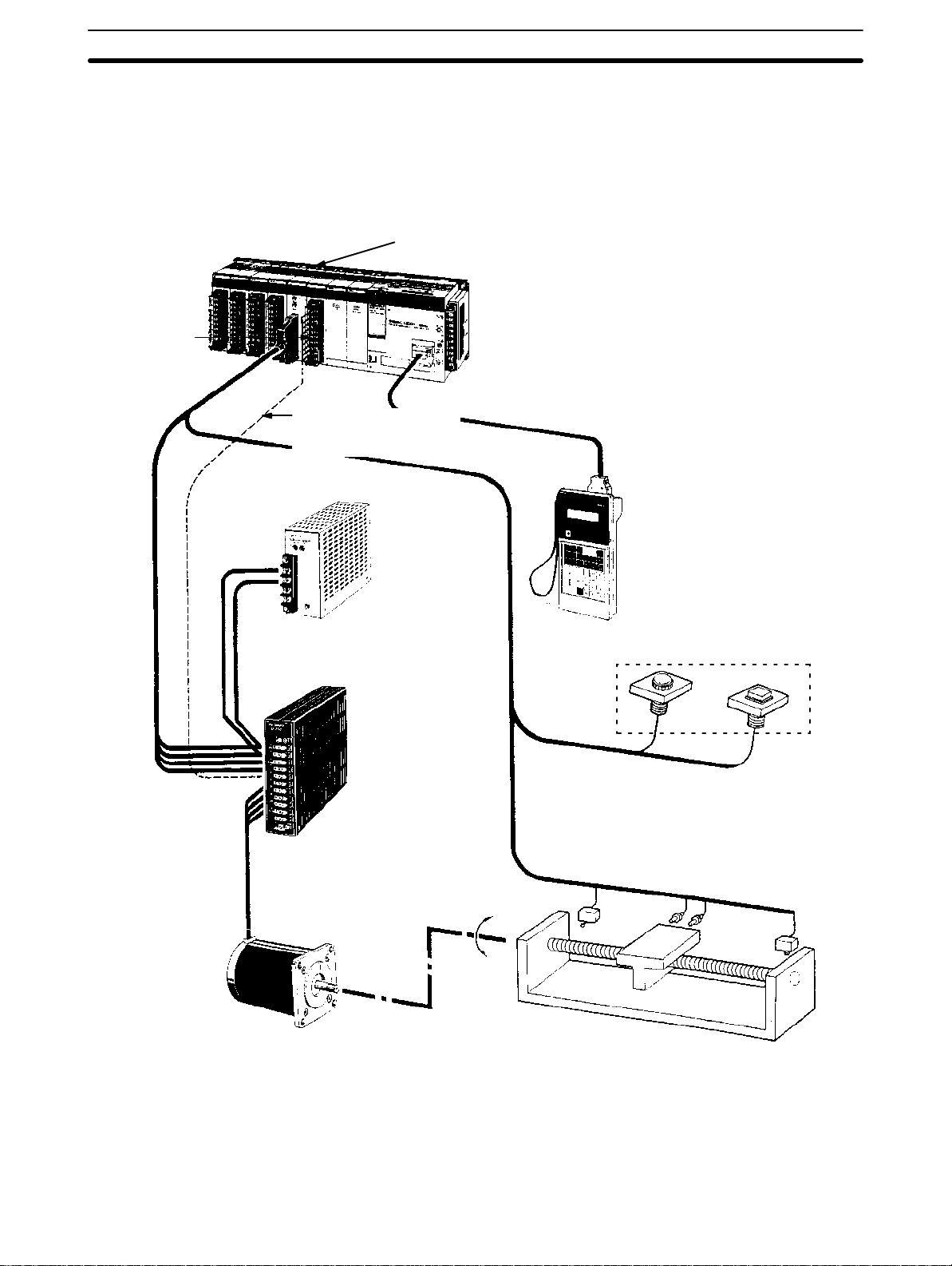
Positioning System Principles Section 1–5
control comes from the program of the PC or from connections to external
inputs (e.g., control panel switches). (Lists of Position Control Unit inputs and
outputs can be found under
uration diagrams show only the positioning system itself. Refer to the operating manuals for other OMRON control devices for details on extended control
system operation.
I/O Circuits
in
Section 2–2
.) The following config-
C200H PC
Input Unit
Position Control Unit C200H-NC112
Stepping motor (or servomotor) driver control
signal line
Power supply
Stepping motor driver
(or servomotor driver)
Hand-held Programming
Console C200H-PRO27
Operation panel
Operation switch
Stepping motor
(or servomotor)
1–5 Positioning System Principles
Positioning systems can be quite simple or relatively complex. The most basic is an open-loop system, in which a particular operation is carried out according to programmed instructions, but in which feedback is not provided for
Control signal input switches
5

Positioning System Principles Section 1–5
automatic adjustments. The C200H-NC112 Position Control Unit can be used
in an open-loop system in conjunction with a stepping motor.
In a closed-loop system, on the other hand, the PC controls an external process without human intervention. The servomotor provides direct feedback
so that actual values (of positions, speeds, and so on) are continuously adjusted to bring them more closely in line with target values. In some systems,
the digital feedback signals will be transmitted to a digital-to-analog converter
to complete the feedback loop, thereby permitting automated control of the
process.
A semiclosed-loop system is similar to a closed-loop system, except that
feedback is provided by a tachogenerator and a rotary encoder rather than
directly by the servomotor. If the C200H-NC112 Position Control Unit is used
with a servomotor, the servomotor driver must be able to handle digital signals. There is therefore no need for a D/A converter. Here, the servomotor is
also connected to a tachogenerator and a rotary encoder.
Both open-loop and semiclosed-loop systems are described in more detail on
the following pages.
6
Positioning System Principles Section 1–5
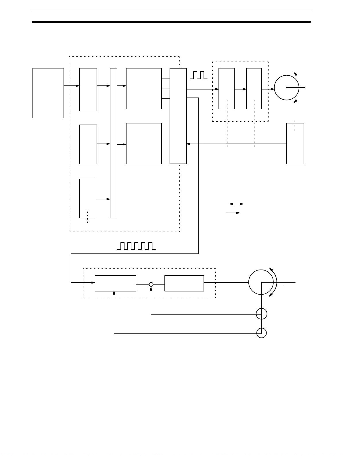
Data Flow
Position Control Unit C200H-NC112
Stepping motor driver
Magnetizing
distributor
circuit
Power
amplifier
Stepping motor
External
input
C200H PC
PC
PC
bus
BUS
I/F
I/F
MPU
Pulse
train
Pulse
generator
I/O Connector
I/O
interface
Memory
Pulse train
Servomotor driver
Error counter Power amplifier
1–5–1 Open-loop System
In an open-loop system, the Position Control Unit outputs pulse trains as
specified by the PC program to control the angle of rotation of the motor. Because the Unit outputs pulse trains, it is generally used with a stepping motor.
The angle of rotation of a stepping motor can be controlled through the number of pulse signals supplied to the motor driver. The number of rotations of
the stepping motor is proportional to the number of pulses supplied by the
Unit, and the rotational speed of the stepping motor is proportional to the frequency of the pulse train.
Servomotor
(Positioning output)
Tachogenerator
Rotary encoder
7
Positioning System Principles Section 1–5
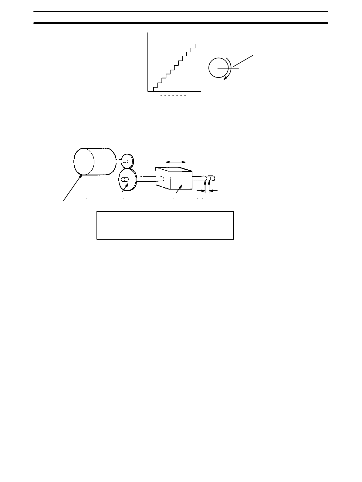
Angle of rotation
Angle of
rotation
Positioning output
1 2 n
Positioning pulse
Simplified Positioning
System Design
S
Reduction gear
Stepping motor
The following diagram and parameters illustrate a simplified positioning system.
V
M
M: Reduction ratio
P: Feed screw pitch (mm/revolution)
V: Feed velocity of object being positioned (mm/s)
Object being
positioned
Feed screw pitch
P
S: Stepping angle per pulse (degree/pulse)
The positioning accuracy in mm/pulse is computed as follows:
Positioning precision = P/(pulses per revolution x M)
= P/((360/S) x M))
= (P x S)/(360 x M)
The required pulse frequency from the Unit in pulses per second is computed
as follows:
Pulse frequency = V/Positioning precision
The required number of pulses to feed an object by a distance L (in mm) is
computed as follows:
Number of pulses = L/Positioning precision
1–5–2 Semiclosed-loop System
When the Position Control Unit is used in a semiclosed-loop system, the system supplies feedback which is used to compensate for any discrepancy between target values and actual values in position or speed. This system detects motor rotation amounts, for example, computes the error between the
target value and actual movement value, and zeroes the error through feedback. The diagram below illustrates the basic configuration of a semiclosed-loop system.
8
= (360 x M x V)/(P x S)
= (360 x M x L)/(P x S)

Positioning System Principles Section 1–5
Target position
Servomotor driver
Error counter Power amplifier
Speed feedback
Position feedback (feedback pulses)
1, 2, 3...
1. First, the target position is transmitted to the error counter in units of encoder pulses. The servomotor driver must be able to handle digital input.
2. The motor rotates at a speed corresponding to the speed voltage. The
rotary encoder connected to the motor axis rotates in sync with the motor, generates feedback pulses, and decrements the error counter.
3. Consequently, the encoder rotation is equivalent to the target position,
and the motor stops rotating when the error counter count and the
speed voltage become zero.
4. While the motor is stopped, the rotary encoder constantly maintains the
stopped position through correction. In the event that the motor axis
moves slightly, the error counter receives a feedback pulse from the
rotary encoder, causing a rotation voltage to be emitted in the reverse
direction from which the rotary encoder moved. This makes the motor
rotate toward its original position. This operation is called servolock or
servoclamp.
5. In order to execute positioning with acceleration and deceleration, target
positions are set consecutively in the error counter for processing.
6. The target position becomes the count for the error counter and controls
the motor by conversion to a speed voltage for the servomotor driver.
The position thus equals the total count of target positions and the
speed will depend on the target position per unit time.
Servomotor
Position output
Tachogenerator
Rotary encoder
9

SECTION 2
Before Operation
Before the Position Control Unit can be operated, switch settings and wiring must be correct. This section presents the
settings and functions of switches, provides examples of and precautions for wiring, and gives dimensions of Units both
when unmounted and mounted. Be sure that all settings and wiring match your positioning system specifications.
2–1 Switch Settings 12 . . . . . . . . . . . . . . . . . . . . . . . . . . . . . . . . . . . . . . . . . . . . . . . . . . . .
2–1–1 Switch Setting Examples 17 . . . . . . . . . . . . . . . . . . . . . . . . . . . . . . . . . . . .
2–2 Wiring 21 . . . . . . . . . . . . . . . . . . . . . . . . . . . . . . . . . . . . . . . . . . . . . . . . . . . . . . . . . . .
2–2–1 Input Connection Examples 27 . . . . . . . . . . . . . . . . . . . . . . . . . . . . . . . . .
2–2–2 Output Connection Examples 29 . . . . . . . . . . . . . . . . . . . . . . . . . . . . . . . .
2–2–3 Wiring Precautions 38 . . . . . . . . . . . . . . . . . . . . . . . . . . . . . . . . . . . . . . . .
2–3 Dimensions 39 . . . . . . . . . . . . . . . . . . . . . . . . . . . . . . . . . . . . . . . . . . . . . . . . . . . . . . .
11
Switch Settings Section 2–1
2–1 Switch Settings
Always turn off PC power before setting the unit number switch. Use a regular screwdriver, being careful not to damage the slot in the screw. Be sure not
to leave the switch midway between settings.
Switch Function
Unit number
(Machine no.)
Mode Used to set the mode from 0 to 3.
Used to set the unit number (between 0 and 9).
Do not set the same number for more than one Special I/O Unit.
Doing so will cause an error and prevent operation.
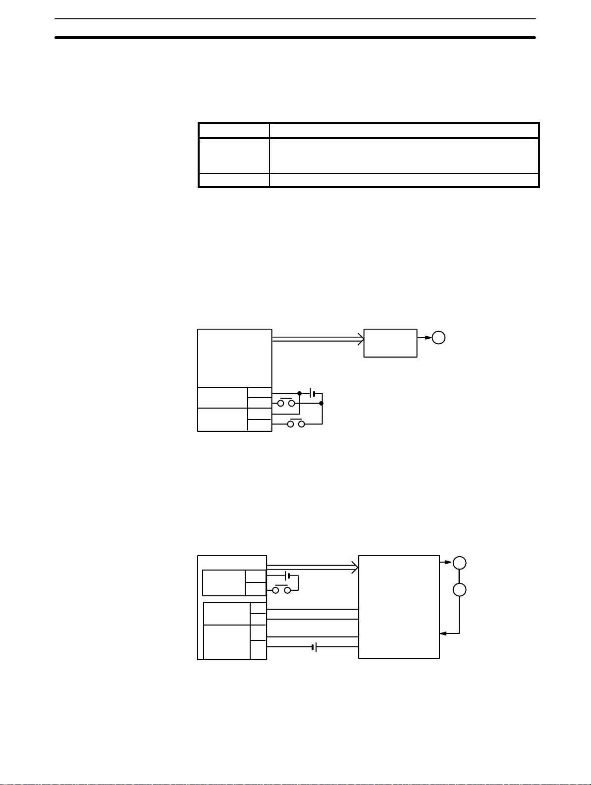
Mode Switch
Mode 0
Mode 1
This switch sets one of operation modes 0 to 3. Select an appropriate operation mode in accordance with the motor driver or signal lines to be used.
Set the Position Control Unit in this mode when it controls a stepping motor
driver. In this mode, connect a sensor to the origin signal lines (connector pin
nos. A11 and B11). The response time of the origin signal is 1 ms.
NC112
Origin
Origin
proximity
A11
B11
A10
B10
Pulse
24 VDC
Pulse motor
driver
M
This mode is used to control a servomotor driver. In this mode, the origin line
driver input signal lines and deviation counter reset output signal lines are
connected, but the driver completed signal lines are not used. The response
time of the origin line driver input signal is 0.1 ms.
Mode 2
12
NC112
Origin
proximity
Origin
line driver
Deviation
counter
reset
A10
B10
A8
B8
A6
B6
Pulse
24 VDC
5 VDC
Servomotor driver
+
Z-phase output
–
Deviation counter
reset input
M
E
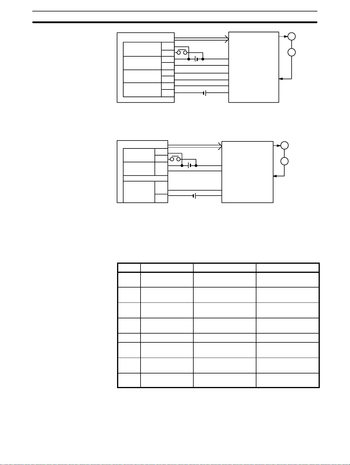
Use this mode when controlling a servomotor driver, and when the driver
completed signal is necessary.
Switch Settings Section 2–1
Mode 3
NC112
Origin
proximity
Positioning
completed
Origin line
driver
Deviation
counter reset
A10
B10
A9
B9
A8
B8
A6
B6
Pulse
5 VDC
24 VDC
Servomotor driver
Driver completed
signal output
+
Z-phase output
–
Deviation counter
reset input
M
E
This mode is used when a servomotor driver having an origin adjustment signal (such as OMRON Model R88D) is used.
NC112
Origin
proximity
Positioning
completed
Origin
adjustment
command
A10
B10
A9
B9
A7
B7
Pulse
24 VDC
5 VDC
Servomotor driver
Driver completed
signal output
Origin adjustment
signal input
M
E
Back Panel DIP Switch
Note The above wiring diagrams for modes 1, 2, and 3 are applicable when an
OMRON R88D Servomotor Driver is used.
Adjust the servomotor driver so that its positioning complete signal turns OFF
while the motor is operating and ON when the motor stops.
These pins must be set before the Unit is mounted.
Pin no. Name ON OFF
1 Output pulse
selector
2 Origin search
direction
3 Origin proximity
present/absent
4 Origin proximity
signal type
5 Origin signal type NO input NC input
6 External interrupt
signal type
7 External interrupt
signal definition
8 Origin proximity
reverse
Nondirectional pulse and
direction signal outputs.
CCW CW
Present Absent
NO input NC input
Fixed via pin #7 Determined by IR word
CHANGE SPEED STOP
Present Absent
Separate CW and CCW
pulse outputs
n, bit 06
Pin 1: Output Pulse
Selector
Note Setting origin proximity to absent is possible in mode 0, but in modes 1, 2, or
3, even if origin proximity is set to absent, operation is performed with origin
proximity present.
When this pin is set to the ON position, the Position Control Unit outputs nondirectional pulses and a direction signal; when it is set to the OFF position,
13

Switch Settings Section 2–1
separate CW and CCW pulses are output. When nondirectional pulses are
output, the direction signal determines the direction of positioning. Set this
pin in accordance with the specifications of the motor and motor driver to be
used.
CW
CCW
ON:
OFF:
Pulses
Direction
CW
CCW
Pin 2: Origin Search
Direction
Pin 3: Origin Proximity
Signal Present/Absent
Output transistor is ON
Output transistor is OFF
This pin selects the direction in which the origin is searched for and the direction from which the origin is reached. If the present position of the positioning
system is near the origin, the origin is searched for in the direction opposite
to that set by this pin.
This pin enables or disables the origin proximity signal. When the pin is set to
ON, ORIGIN SEARCH is executed using the origin and origin proximity signals. (Note that the origin proximity signal is necessary in modes 1, 2, and 3.)
14
Switch Settings Section 2–1
Origin proximity
Origin
(When searching for the
origin in the CCW direction)
CCW
Positioning axis
ORIGIN SEARCH (Start)
CCW
CCW
Origin
(When searching for the
origin in the CW direction)
Origin (Stop)
CW
Origin (Stop)
ORIGIN SEARCH (Start)
CW
Origin (Stop)
ORIGIN SEARCH (Start)
CW limit
When the pin is set to OFF, ORIGIN SEARCH is executed completely at
proximity speed (low speed).
CCW
ORIGIN SEARCH (Start)
CCW
CCW
Pin 4: Origin Proximity
Signal Type and
Pin 5: Origin Signal Type
Origin (Stop)
Origin (Stop)
ORIGIN SEARCH (Start)
ORIGIN SEARCH (Start)Origin (Stop)
Positioning axis
CW limit
CW
CW
CW
These pins determine whether the origin proximity and origin signals are input from NO or NC contacts. When the pin is set to ON, the corresponding
signal is input from an NO contact; when set to OFF, from an NC contact.
15
Switch Settings Section 2–1
NO contact
NC contact
Pin 6: External Interrupt
Signal Type and
Pin 7: External Interrupt
Signal Definition
Pin 8: Origin Proximity
Reverse
Origin proximity
Origin (Z phase)
Pulse output
CCW
ORIGIN SEARCH (Start)
External interrupt processing is determined by pins 6 and 7 in combination
with bit 06 of IR word n (n = 100 + 10 x unit number). See
Section 4–10
for
details.
This pin selects whether the origin is detected after the origin proximity signal
has turned ON or after it has turned ON once and then OFF.
When the pin is set to ON, origin proximity reverse is enabled. You can use
this function to make sure that a sufficient deceleration period elapses when
there are multiple origin signals. Set the origin proximity signal such that it
remains on longer than the deceleration period. In the following example diagram, ORIGIN SEARCH is executed in the counterclockwise direction.
CW
Origin (Stop)
Positioning axis
16
CCW
CCW
CW
Origin (Stop)ORIGIN SEARCH (Start)
CW
Origin (Stop)
ORIGIN SEARCH (Start)
CW limit
When the pin is set to OFF, origin proximity reverse is disabled and the origin
signal is detected after the origin proximity signal has turned ON. Note, however, that the origin signal is not detected in modes 1, 2, and 3 during deceleration, and that the origin adjustment signal is not output in mode 3 during
deceleration. Make sure, therefore, that deceleration is completed by the
time the first origin signal is output after the origin proximity signal is turned
on.
For details, refer to
Section 4–2
.
Switch Settings Section 2–1
Origin proximity
Origin (Z phase)
Pulse output
Positioning axis
CCW
CW
ORIGIN SEARCH (Start)
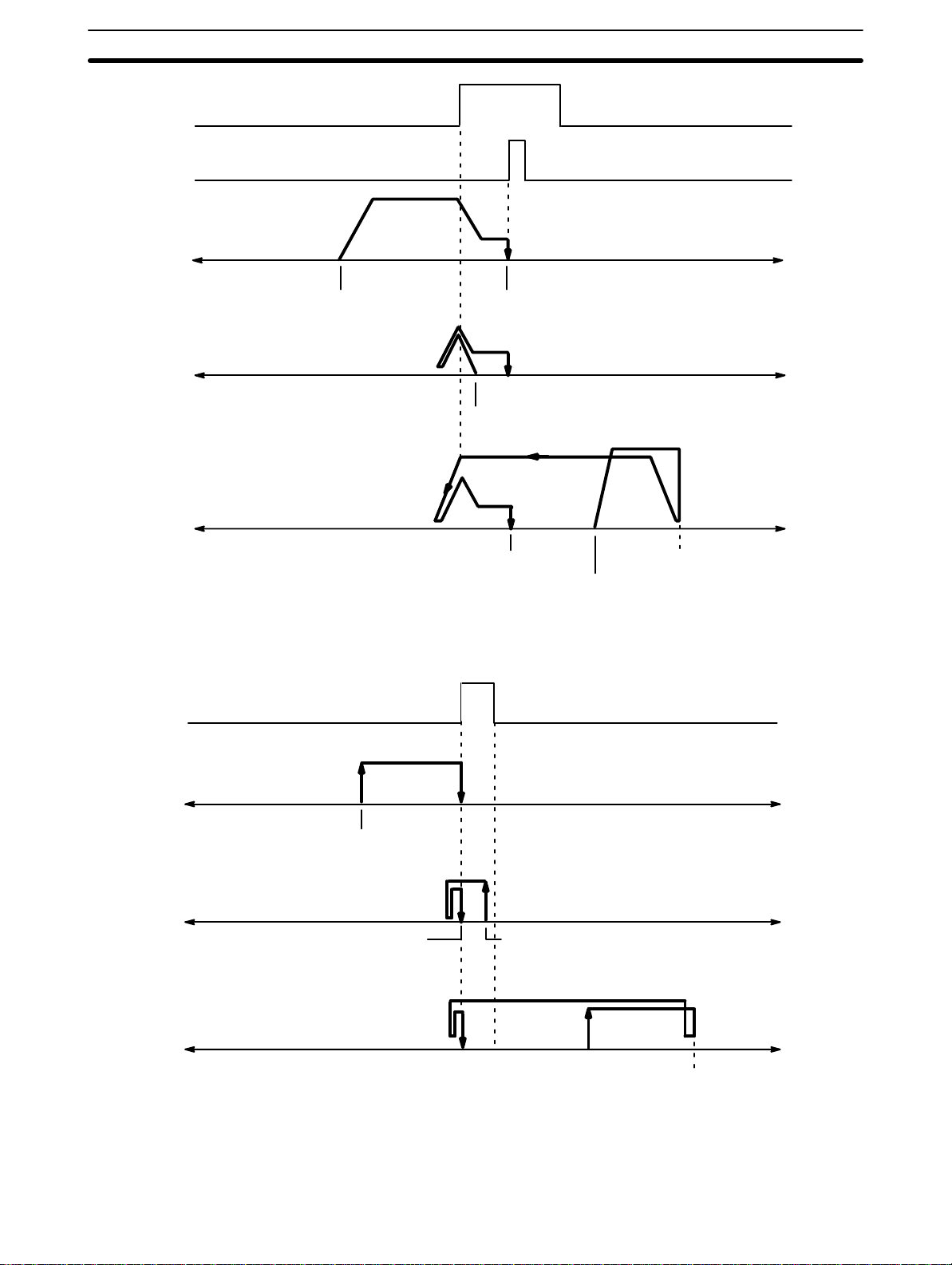
2–1–1 Switch Setting Examples
The examples in this section show switch settings for ORIGIN SEARCH in
each of the four Position Control Unit modes. In every case, set the appropriate unit number and mode first, as described at the beginning of
Example 1:
Settings in Mode 0
See also
In this example, the mode switch is set to 0 and the DIP switch pins are set
as follows:
1 OFF CW/CCW output
2 ON Origin search direction: CCW
3 ON Origin proximity present
4 ON Origin proximity signal from NO input (rising edge)
5 ON Origin signal from NO input (rising edge)
6 Refer to
7
8 OFF Origin proximity reverse absent (rising edge)
Origin search is started after the rising edge of the origin proximity signal and
ends with the rising edge of the origin signal.
Section 4–2
Origin (Stop)
.
Section 4–10 External Interrupt Commands
Section 2–1.
.
17
Switch Settings Section 2–1
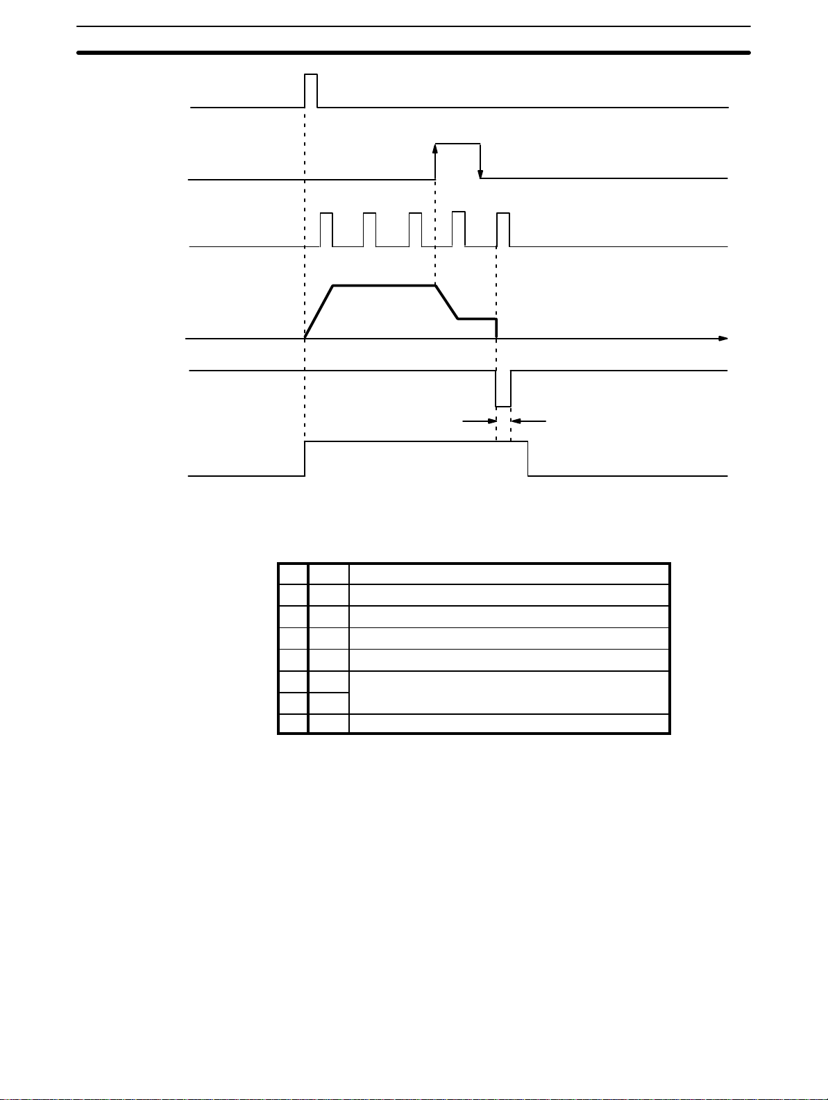
ORIGIN SEARCH
Origin proximity signal
Origin signal
Pulse output
Busy flag
Example 2: Settings in
Mode 1
Time
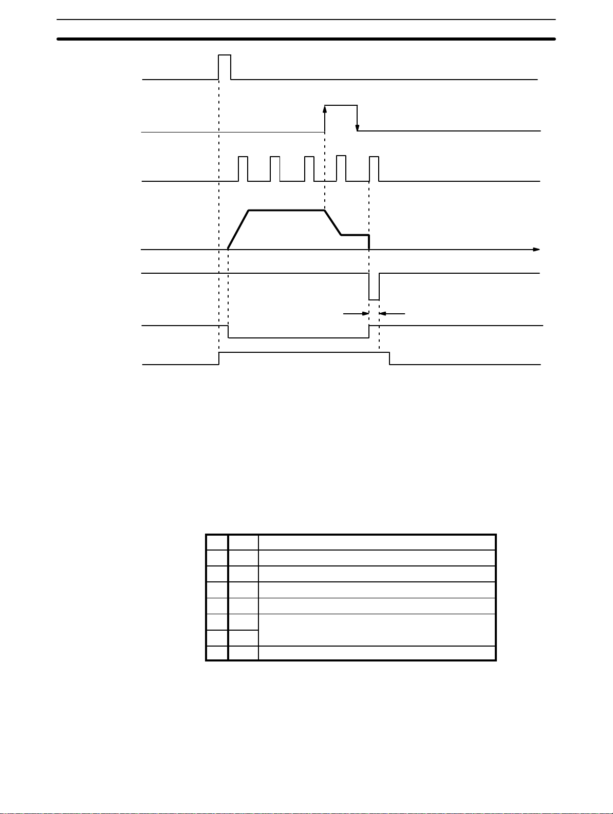
In this example, the mode switch is set to 1 and the DIP switch pins are set
as follows:
1 OFF CW/CCW output
2 ON Origin search direction: CCW
3 ON Origin proximity present
4 ON Origin proximity signal from NO input (rising edge)
5 ON Origin signal from NO input (rising edge)
6 Refer to
7
8 ON Origin proximity reverse present (rising, falling edge)
Section 4–10 External Interrupt Commands
.
Origin search is started after the origin proximity signal has risen and fallen,
and stops with completion of the first Z-phase signal after deceleration has
stopped.
18
Switch Settings Section 2–1
ORIGIN SEARCH
Origin proximity signal
Z-phase signal
Pulse output
Deviation counter reset output
Busy flag
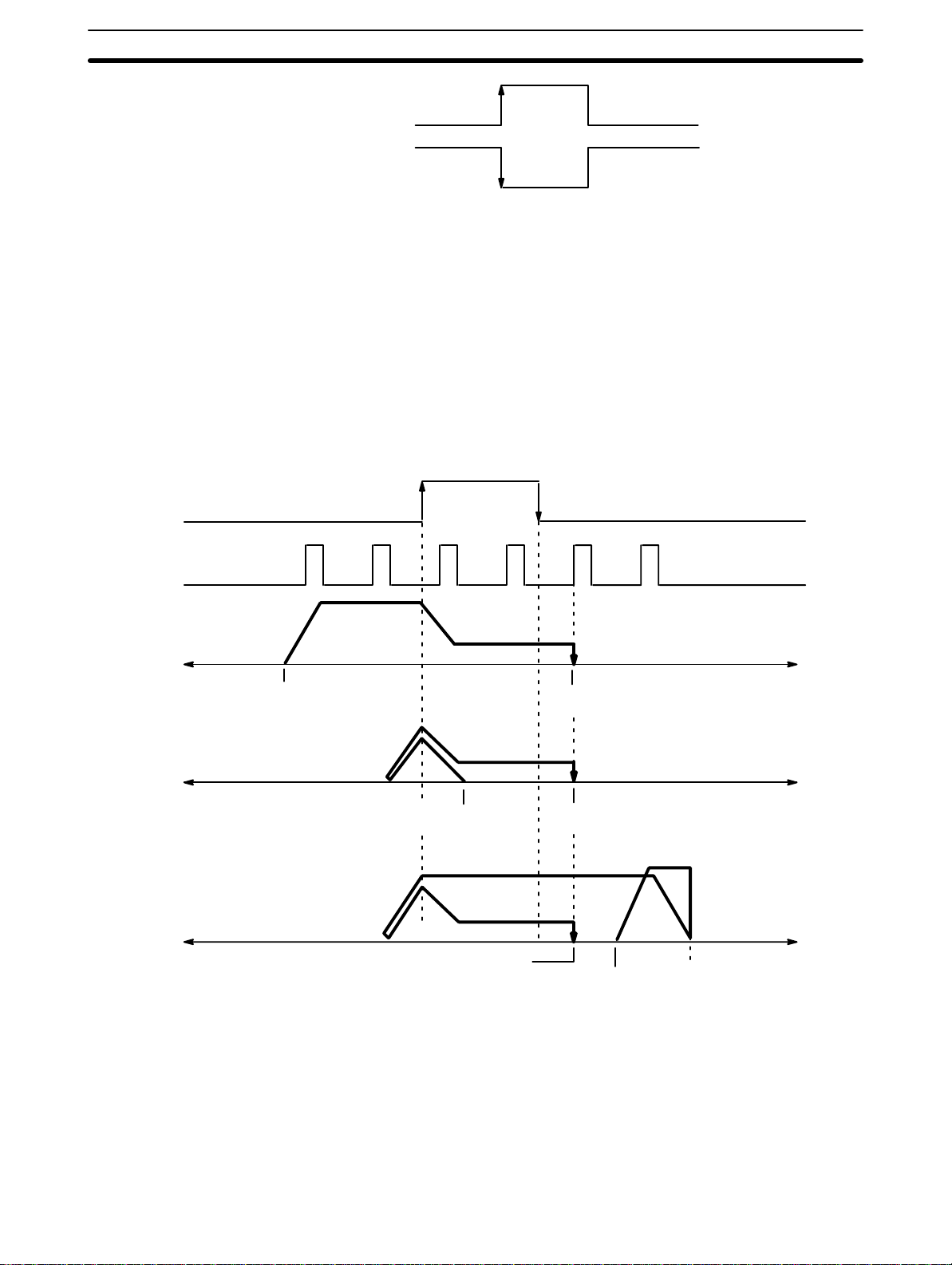
Example 3:
Settings in Mode 2
Time
Approx. 30 ms
In this example, the mode switch is set to 2 and the DIP switch pins are set
as follows:
1 OFF CW/CCW output
2 ON Origin search direction: CCW
3 ON Origin proximity present
4 ON Origin proximity signal from NO input (rising edge)
5 ON Origin signal from NO input (rising edge)
6 Refer to
7
8 ON Origin proximity reverse present (rising, falling edge)
Section 4–10 External Interrupt Commands
.
Origin search is started after the origin proximity signal has risen and fallen,
and stops with completion of the first Z-phase signal after deceleration has
stopped.
19
Switch Settings Section 2–1
ORIGIN SEARCH
Origin proximity signal
Z-phase signal
Pulse output
Deviation counter
reset output
Driver completed input
Busy flag
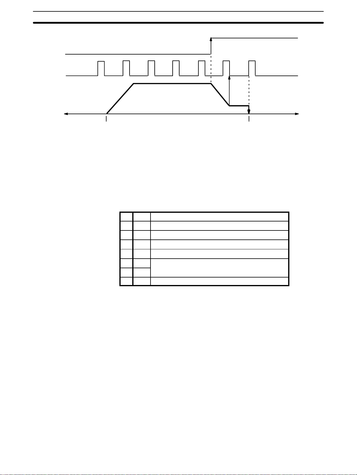
Example 4:
Settings in Mode 3
Time
Approx. 30 ms
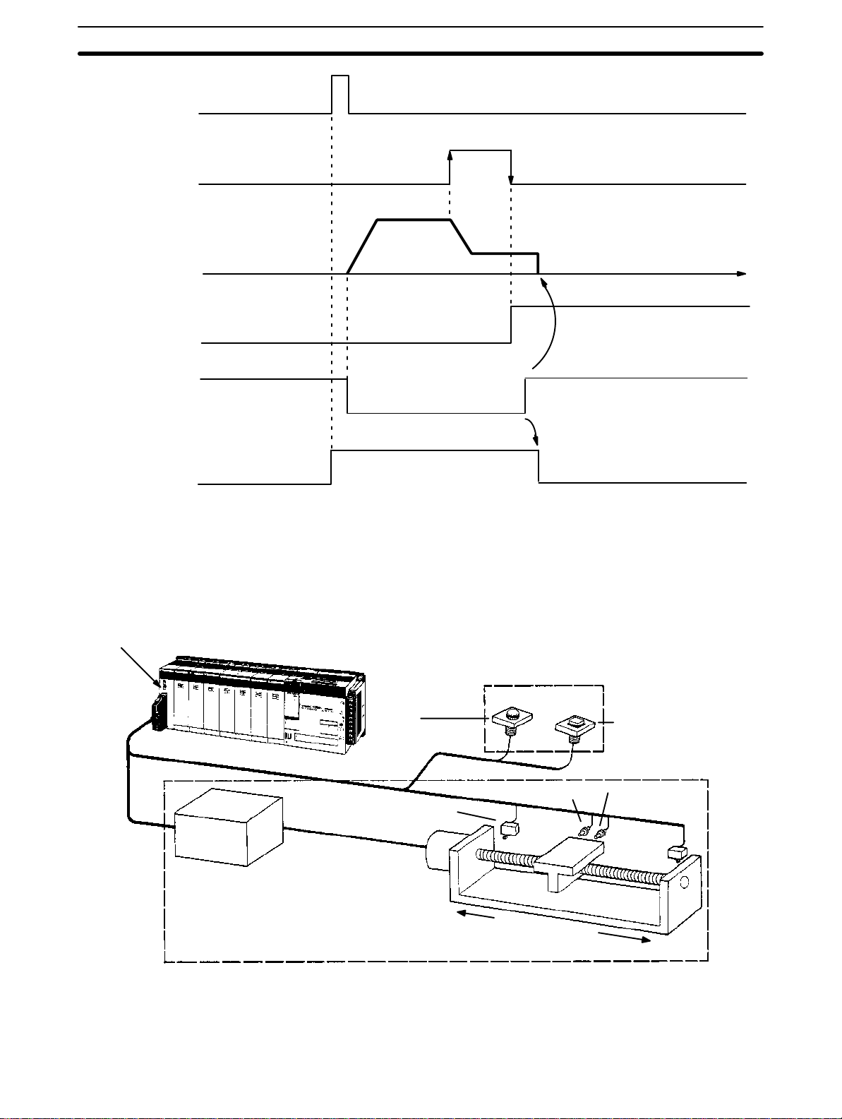
In this example, the mode switch is set to 3 and the DIP switch pins are set
as follows:
20
1 OFF CW/CCW output
2 ON Origin search direction: CCW
3 ON Origin proximity present
4 ON Origin proximity signal from NO input (rising edge)
5 ON Origin signal from NO input (rising edge)
6 Refer to
7
8 ON Origin proximity reverse present (rising, falling edge)
Section 4–10 External Interrupt Commands
.
Origin search is started after the origin proximity signal has risen and fallen,
and the origin adjustment signal is output to the servomotor driver after deceleration is completed. The positioning completed signal is then input from
the servomotor driver and origin search ends. The servomotor driver stops
automatically with the first Z-phase input after it has received the origin adjustment signal.
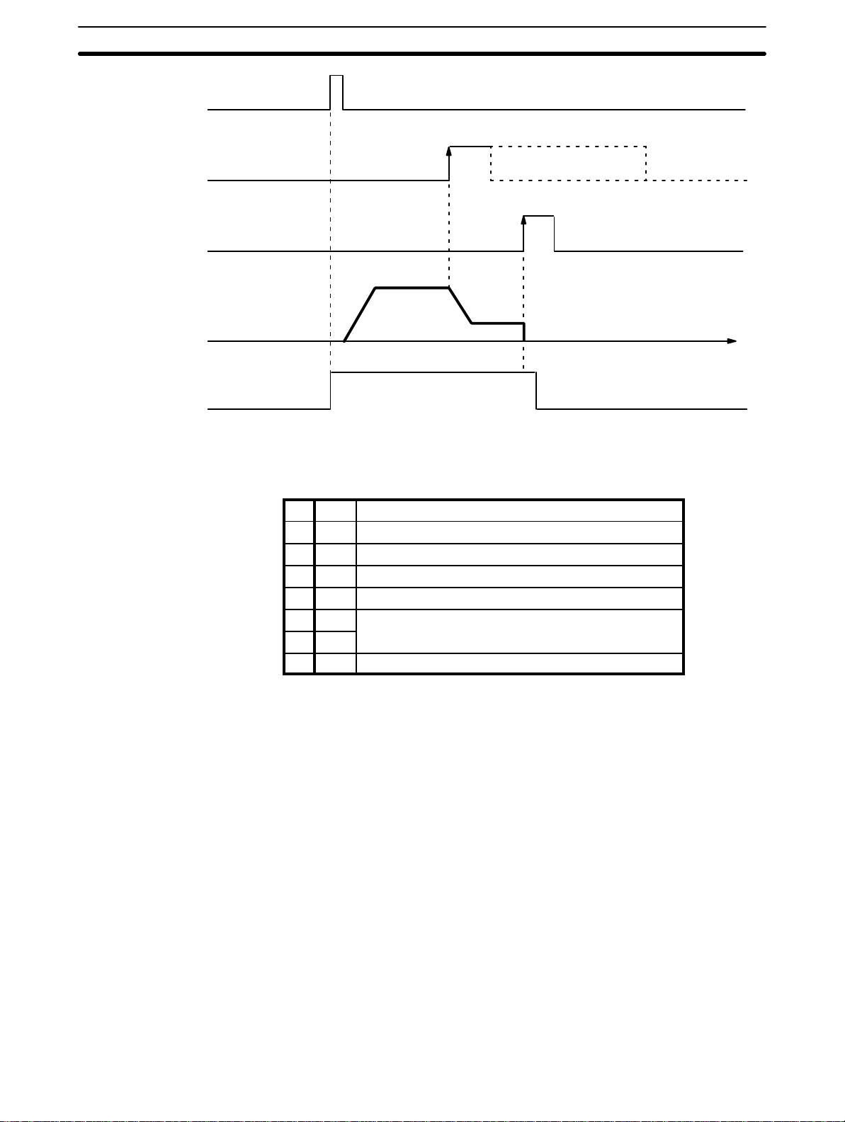
Wiring Section 2–2
ORIGIN SEARCH
Origin proximity signal
Pulse output
Origin adjustment
command output
Driver completed input
Busy flag
2–2 Wiring
External I/O Connections
Position Control Unit
C200H-NC112
Time
The example diagram below shows I/O connections.
C200H PC
Control panel
Output
Input
Motor
driver
Emergency stop
switch
CCW limit switch
Motor
Origin switch (sensor)
CCW
CW
External interrupt
switch
Mechanical system
Origin proximity
switch
CW limit
switch
Connector Pin Arrangement The following I/O connector pin arrangement is as viewed from the front of
the Position Control Unit.
21
 Loading...