

Page 1
Cat. No. W137-E1-04
SYSMAC
C200H-NC111
Position Control Unit
Page 2
SYSMAC C200H-NC111
Position Control Unit
Operation Manual
Revised September 2003
Page 3

iv
Page 4

!
!
!
v
Notice:
OMRON products are manufactured for use according to proper procedures by a qualified operator
and only for the purposes described in this manual.
The following conventions are used to indicate and classify precautions in this manual. Always heed
the information provided with them. Failure to heed precautions can result in injury to people or damage to property.
DANGER Indicates an imminently hazardous situation which, if not avoided, will result in death or
serious injury.
WARNING Indicates a potentially hazardous situation which, if not avoided, could result in death or
serious injury.
Caution Indicates a potentially hazardous situation which, if not avoided, may result in minor or
moderate injury, or property damage.
OMRON Product References
All OMRON products are capitalized in this manual. The word “Unit” is also capitalized when it refers
to an OMRON product, regardless of whether or not it appears in the proper name of the product.
The abbreviation “Ch,” which appears in some displays and on some OMRON products, often means
“word” and is abbreviated “Wd” in documentation in this sense.
The abbreviation “PC” means Programmable Controller and is not used as an abbreviation for anything else.
Visual Aids
The following headings appear in the left column of the manual to help you locate different types of
information.
Note Indicates information of particular interest for efficient and convenient operation
of the product.
1, 2, 3... 1. Indicates lists of one sort or another, such as procedures, checklists, etc.
OMRON, 1990
All rights reserved. No part of this publication may be reproduced, stored in a retrieval system, or transmitted, in any
form, or by any means, mechanical, electronic, photocopying, recording, or otherwise, without the prior written permission of OMRON.
No patent liability is assumed with respect to the use of the information contained herein. Moreover, because OMRON is
constantly striving to improve its high–quality products, the information contained in this manual is subject to change
without notice. Every precaution has been taken in the preparation of this manual. Nevertheless, OMRON assumes no
responsibility for errors or omissions. Neither is any liability assumed for damages resulting from the use of the information contained in this publication.
Page 5

vi
Page 6

vii
TABLE OF CONTENTS
PRECAUTIONS xi. . . . . . . . . . . . . . . . . . . . . . . . . . . . . . . . .
1 Intended Audience xii. . . . . . . . . . . . . . . . . . . . . . . . . . . . . . . . . . . . . . . . . . . . . . . . . . . . . . . . . . .
2 General Precautions xii. . . . . . . . . . . . . . . . . . . . . . . . . . . . . . . . . . . . . . . . . . . . . . . . . . . . . . . . . .
3 Safety Precautions xii. . . . . . . . . . . . . . . . . . . . . . . . . . . . . . . . . . . . . . . . . . . . . . . . . . . . . . . . . . .
4 Operating Environment Precautions xiii. . . . . . . . . . . . . . . . . . . . . . . . . . . . . . . . . . . . . . . . . . . . .
5 Application Precautions xiii. . . . . . . . . . . . . . . . . . . . . . . . . . . . . . . . . . . . . . . . . . . . . . . . . . . . . .
SECTION 1
Introduction 1. . . . . . . . . . . . . . . . . . . . . . . . . . . . . . . . . . . .
1–1 Features 2. . . . . . . . . . . . . . . . . . . . . . . . . . . . . . . . . . . . . . . . . . . . . . . . . . . . . . . . . . . . . . .
1–2 Components 2. . . . . . . . . . . . . . . . . . . . . . . . . . . . . . . . . . . . . . . . . . . . . . . . . . . . . . . . . . . .
1–3 System Configuration 3. . . . . . . . . . . . . . . . . . . . . . . . . . . . . . . . . . . . . . . . . . . . . . . . . . . . .
1–4 Control System Principles 5. . . . . . . . . . . . . . . . . . . . . . . . . . . . . . . . . . . . . . . . . . . . . . . . .
SECTION 2
Before Operation 11. . . . . . . . . . . . . . . . . . . . . . . . . . . . . . . .
2–1 Switch Settings 12. . . . . . . . . . . . . . . . . . . . . . . . . . . . . . . . . . . . . . . . . . . . . . . . . . . . . . . . . .
2–2 Wiring 13. . . . . . . . . . . . . . . . . . . . . . . . . . . . . . . . . . . . . . . . . . . . . . . . . . . . . . . . . . . . . . . . .
2–3 Dimensions 24. . . . . . . . . . . . . . . . . . . . . . . . . . . . . . . . . . . . . . . . . . . . . . . . . . . . . . . . . . . . .
SECTION 3
Operation 25. . . . . . . . . . . . . . . . . . . . . . . . . . . . . . . . . . . . . .
3–1 Operational Flow 26. . . . . . . . . . . . . . . . . . . . . . . . . . . . . . . . . . . . . . . . . . . . . . . . . . . . . . . .
3–2 Output Pulses 28. . . . . . . . . . . . . . . . . . . . . . . . . . . . . . . . . . . . . . . . . . . . . . . . . . . . . . . . . . .
3–3 Writing Data 28. . . . . . . . . . . . . . . . . . . . . . . . . . . . . . . . . . . . . . . . . . . . . . . . . . . . . . . . . . . .
3–4 Data Configuration and Allocation 29. . . . . . . . . . . . . . . . . . . . . . . . . . . . . . . . . . . . . . . . . .
3–5 IR Area Data Format 32. . . . . . . . . . . . . . . . . . . . . . . . . . . . . . . . . . . . . . . . . . . . . . . . . . . . .
3–6 Flags and Other Input Data 33. . . . . . . . . . . . . . . . . . . . . . . . . . . . . . . . . . . . . . . . . . . . . . . .
3–7 DM Area Allocation 33. . . . . . . . . . . . . . . . . . . . . . . . . . . . . . . . . . . . . . . . . . . . . . . . . . . . . .
SECTION 4
Commands 43. . . . . . . . . . . . . . . . . . . . . . . . . . . . . . . . . . . . .
4–1 Start 44. . . . . . . . . . . . . . . . . . . . . . . . . . . . . . . . . . . . . . . . . . . . . . . . . . . . . . . . . . . . . . . . . .
4–2 Origin Search 55. . . . . . . . . . . . . . . . . . . . . . . . . . . . . . . . . . . . . . . . . . . . . . . . . . . . . . . . . . .
4–3 Origin Return 63. . . . . . . . . . . . . . . . . . . . . . . . . . . . . . . . . . . . . . . . . . . . . . . . . . . . . . . . . . .
4–4 Release Prohibit 65. . . . . . . . . . . . . . . . . . . . . . . . . . . . . . . . . . . . . . . . . . . . . . . . . . . . . . . . .
4–5 Read Error 68. . . . . . . . . . . . . . . . . . . . . . . . . . . . . . . . . . . . . . . . . . . . . . . . . . . . . . . . . . . . .
4–6 Reset Origin 69. . . . . . . . . . . . . . . . . . . . . . . . . . . . . . . . . . . . . . . . . . . . . . . . . . . . . . . . . . . .
4–7 Teach 69. . . . . . . . . . . . . . . . . . . . . . . . . . . . . . . . . . . . . . . . . . . . . . . . . . . . . . . . . . . . . . . . .
4–8 Transfer Data 71. . . . . . . . . . . . . . . . . . . . . . . . . . . . . . . . . . . . . . . . . . . . . . . . . . . . . . . . . . .
4–9 Manual Operations 78. . . . . . . . . . . . . . . . . . . . . . . . . . . . . . . . . . . . . . . . . . . . . . . . . . . . . . .
4–10 External Interrupt Commands 81. . . . . . . . . . . . . . . . . . . . . . . . . . . . . . . . . . . . . . . . . . . . . .
Page 7

viii
SECTION 5
Programming Examples 91. . . . . . . . . . . . . . . . . . . . . . . . . .
5–1 Operation with Minimum Data: Displaying JOG Positions 92. . . . . . . . . . . . . . . . . . . . . . .
5–2 Positioning at Intervals: Using RESET ORIGIN 94. . . . . . . . . . . . . . . . . . . . . . . . . . . . . . . .
5–3 Feeding Selectively with START 96. . . . . . . . . . . . . . . . . . . . . . . . . . . . . . . . . . . . . . . . . . . .
5–4 Transfer Data from Other PC Areas 96. . . . . . . . . . . . . . . . . . . . . . . . . . . . . . . . . . . . . . . . . .
5–5 Transfer Data from External Switches 99. . . . . . . . . . . . . . . . . . . . . . . . . . . . . . . . . . . . . . . .
5–6 Using START to Carry Out Positioning Actions 101. . . . . . . . . . . . . . . . . . . . . . . . . . . . . . . .
5–7 Using Origin and Origin Proximity Signals 105. . . . . . . . . . . . . . . . . . . . . . . . . . . . . . . . . . . .
5–8 Using Zones to Control Jogging 106. . . . . . . . . . . . . . . . . . . . . . . . . . . . . . . . . . . . . . . . . . . .
5–9 Controlling an R88D-EP06 Servodriver 107. . . . . . . . . . . . . . . . . . . . . . . . . . . . . . . . . . . . . .
5–10 Controlling a V-series Servodriver 110. . . . . . . . . . . . . . . . . . . . . . . . . . . . . . . . . . . . . . . . . . .
SECTION 6
Error Processing 111. . . . . . . . . . . . . . . . . . . . . . . . . . . . . . . .
6–1 Alarms and Errors 112. . . . . . . . . . . . . . . . . . . . . . . . . . . . . . . . . . . . . . . . . . . . . . . . . . . . . . .
6–2 Outputs to the IR Area 112. . . . . . . . . . . . . . . . . . . . . . . . . . . . . . . . . . . . . . . . . . . . . . . . . . . .
6–3 Alarm/Error Indicators 112. . . . . . . . . . . . . . . . . . . . . . . . . . . . . . . . . . . . . . . . . . . . . . . . . . . .
6–4 Troubleshooting from the PC 112. . . . . . . . . . . . . . . . . . . . . . . . . . . . . . . . . . . . . . . . . . . . . . .
6–5 Basic Troubleshooting Chart 115. . . . . . . . . . . . . . . . . . . . . . . . . . . . . . . . . . . . . . . . . . . . . . .
6–6 Detection of Abnormal Pulse Outputs 116. . . . . . . . . . . . . . . . . . . . . . . . . . . . . . . . . . . . . . . .
Appendices
A Alarm Code List 119. . . . . . . . . . . . . . . . . . . . . . . . . . . . . . . . . . . . . . . . . . . . . . . . . . . . . . . . . . . .
B Error Code List 123. . . . . . . . . . . . . . . . . . . . . . . . . . . . . . . . . . . . . . . . . . . . . . . . . . . . . . . . . . . . .
C DM Area Allocations 127. . . . . . . . . . . . . . . . . . . . . . . . . . . . . . . . . . . . . . . . . . . . . . . . . . . . . . . .
D IR Area Allocations 133. . . . . . . . . . . . . . . . . . . . . . . . . . . . . . . . . . . . . . . . . . . . . . . . . . . . . . . . .
E Specifications 137. . . . . . . . . . . . . . . . . . . . . . . . . . . . . . . . . . . . . . . . . . . . . . . . . . . . . . . . . . . . . .
F Standard Models 139. . . . . . . . . . . . . . . . . . . . . . . . . . . . . . . . . . . . . . . . . . . . . . . . . . . . . . . . . . . .
Glossary 141. . . . . . . . . . . . . . . . . . . . . . . . . . . . . . . . . . . . . . .
Index 147. . . . . . . . . . . . . . . . . . . . . . . . . . . . . . . . . . . . . . . . . .
Revision History 151. . . . . . . . . . . . . . . . . . . . . . . . . . . . . . . . .
Page 8

ix
About this Manual:
The C200H–NC111 Position Control Unit is a Special I/O Unit for C200H PCs. It is designed to control
equipment positioning through pulse train outputs to a motor driver. The degree of movement is
based on the program installed into the PC and the external control inputs.
This manual covers the specifications and procedures necessary for installation and efficient operation. Before attempting to operate the C200H Position Control Unit, be sure to thoroughly familiarize
yourself with the information contained within this and any other relevant manuals.
Section 1 describes the basic features and components of the Position Control Unit. It also gives details on configurations for positioning control systems and their principles of operation.
Section 2 describes how to incorporate the Positioning Control Unit into a system. It provides information on how to set switches so that the Unit provides the desired operating functions. It also gives
mounting and wiring information.
Section 3 gives details on the procedures for setting up and operating a positioning control system. It
includes information on PC operations (such as flags, zone settings, the range of output pulses, backlash compensation, etc.), data areas and data formats.
Section 4 outlines the thirteen commands available on the Positioning Control Unit. It describes each
command, how it works, the data required,and the data areas used. Examples are given (in timing
chart form) which show the status of the relevant inputs, outputs, bits, and flags during the execution
of the commands.
Section 5 provides programming examples which give practical illustrations of how the Positioning
Control Unit commands can be used to implement effective positioning control.
Section 6 explains various error and alarm conditions and the steps that can be taken to avoid and/or
prevent them.
Appendix A provides more detailed information on alarm codes, including the type of operations in
which the alarm may arise, the type of error, the alarm code, and the most probable cause.
Appendix B lists the error codes in numeric sequence and provides information on the cause of, and
remedy for, the existing problem.
Appendix C describes the functions that each of the different parts of the DM Area performs.
Appendix D describes the functions for which each of the different parts of the IR Area can be used.
Appendix E provides the performance and electrical specifications for the Positioning Control Unit.
Appendix F lists the models which are used with the Positioning Control Unit.
A comprehensive Glossary is provided which explains many of the terms and abbreviations commonly used when referring to Positioning Control Units and PC Systems.
WARNING Failure to read and understand the information provided in this manual may result in
personal injury or death, damage to the product, or product failure. Please read each
section in its entirety and be sure you understand the information provided in the section
and related sections before attempting any of the procedures or operations given.
!
Page 9

xi
PRECAUTIONS
This section provides general precautions for using the Programmable Controller (PC), Position Control Unit (PCU), and
related devices.
The information contained in this section is important for the safe and reliable application of the Programmable Controller and the Position Control Unit. You must read this section and understand the information contained before
attempting to set up or operate a PC system.
1 Intended Audience xii. . . . . . . . . . . . . . . . . . . . . . . . . . . . . . . . . . . . . . . . . . . . . . . . . . . . . . . . . . . .
2 General Precautions xii. . . . . . . . . . . . . . . . . . . . . . . . . . . . . . . . . . . . . . . . . . . . . . . . . . . . . . . . . . .
3 Safety Precautions xii. . . . . . . . . . . . . . . . . . . . . . . . . . . . . . . . . . . . . . . . . . . . . . . . . . . . . . . . . . . .
4 Operating Environment Precautions xiii. . . . . . . . . . . . . . . . . . . . . . . . . . . . . . . . . . . . . . . . . . . . . .
5 Application Precautions xiii. . . . . . . . . . . . . . . . . . . . . . . . . . . . . . . . . . . . . . . . . . . . . . . . . . . . . . . .
Page 10

!
!
!
5Safety Precautions
xii
1 Intended Audience
This manual is intended for the following personnel, who must also have knowledge of electrical systems (an electrical engineer or the equivalent).
• Personnel in charge of installing FA systems.
• Personnel in charge of designing FA systems.
• Personnel in charge of managing FA systems and facilities.
2 General Precautions
The user must operate the product according to the performance specifications
described in the operation manuals.
Before using the product under conditions which are not described in the manual
or applying the product to nuclear control systems, railroad systems, aviation
systems, vehicles, combustion systems, medical equipment, amusement
machines, safety equipment, and other systems, machines, and equipment that
may have a serious influence on lives and property if used improperly, consult
your OMRON representative.
Make sure that the ratings and performance characteristics of the product are
sufficient for the systems, machines, and equipment, and be sure to provide the
systems, machines, and equipment with double safety mechanisms.
This manual provides information for programming and operating Position Control Unit. Be sure to read this manual before attempting to use the PCU and keep
this manual close at hand for reference during operation.
3 Safety Precautions
WARNING Never attempt to disassemble any Units while power is being supplied. Doing so
may result in serious electrical shock or electrocution.
WARNING Never touch any of the terminals while power is being supplied. Doing so may
result in serious electrical shock or electrocution.
WARNING Provide safety measures in external circuits (i.e., not in the Programmable
Controller), including the following items, to ensure safety in the system if an
abnormality occurs due to malfunction of the PC or another external factor
affecting the PC operation. Not doing so may result in serious accidents.
• Emergency stop circuits, interlock circuits, limit circuits, and similar safety
measures must be provided in external control circuits.
• The PC will turn OFF all outputs when its self-diagnosis function detects any
error or when a severe failure alarm (FALS) instruction is executed. As a countermeasure for such errors, external safety measures must be provided to
ensure safety in the system.
• The PC outputs may remain ON or OFF due to deposits on or burning of the
output relays, or destruction of the output transistors. As a countermeasure for
such problems, external safety measures must be provided to ensure safety in
the system.
• When the 24-V DC output (service power supply to the PC) is overloaded or
short-circuited, the voltage may drop and result in the outputs being turned
OFF . As a countermeasure for such problems, external safety measures must
be provided to ensure safety in the system.
Page 11

!
!
5Application Precautions
xiii
4 Operating Environment Precautions
Do not operate the control system in the following places.
• Locations subject to direct sunlight.
• Locations subject to temperatures or humidity outside the range specified in
the specifications.
• Locations subject to condensation as the result of severe changes in temperature.
• Locations subject to corrosive or flammable gases.
• Locations subject to dust (especially iron dust) or salts.
• Locations subject to shock or vibration.
• Locations subject to exposure to water, oil, or chemicals.
• Take appropriate and sufficient countermeasures when installing systems in
the following locations.
• Locations subject to static electricity or other forms of noise.
• Locations subject to strong electric fields or magnetic fields.
• Locations subject to possible exposure to radioactivity.
• Locations close to power supplies.
5 Application Precautions
Observe the following precautions when using the Position Control Unit (PCU)
and Programmable Controller (PC).
WARNING Failure to abide by the following precautions could lead to serious or possibly
fatal injury. Always heed these precautions.
• Always ground the system to 100 Ω or less when installing the system to protect against electrical shock.
• Always turn off the power supply to the PC before attempting any of the following:
• Mounting or dismounting the Power Supply Unit, I/O Units, CPU Unit,
other Units, or Memory Casettes.
• Assembling the devices.
• Setting DIP switches or rotary switches.
• Wiring or connecting cables.
• Connecting or disconnecting the connectors.
Caution Failure to abide by the following precautions could lead to faulty operation of the
PC or the system or could damage the PC or PC Units. Always heed these precautions.
• Fail-safe measures must be taken by the customer to ensure safety in the
event of incorrect, missing, or abnormal signals caused by broken signal lines,
momentary power interruptions, or other causes.
• Interlock circuits, limit circuits, and similar safety measures must be provided
by the customer as external circuits.
• Install external breakers and take other safety measures against short-circuiting in external wiring.
• Tighten the PC mounting screws, terminal block screws, and cable screws to
the torque specified in this manuals.
• Always use the power supply voltage specified in this manual.
Page 12

5Application Precautions
xiv
• Take appropriate measures to ensure that the specified power with the rated
voltage and frequency is supplied. Be particularly careful in places where the
power supply is unstable.
• Use crimp terminals for wiring. Do not connect bare stranded wires directly to
terminals.
• Leave the dustproof labels affixed to the top of the Unit when wiring. After wiring, remove the labels for proper heat radiation.
• Do not apply voltages to the Input Units in excess of the rated input voltage.
• Do not apply voltages or connect loads to the Output Units in excess of the
maximum switching capacity.
• Check the user program for proper execution before actually running it in the
Unit.
• Be sure that the terminal blocks, memory units, extension cables, and other
items with locking devices are properly locked.
• Double-check all the wiring before turning on the power supply.
• Disconnect the functional ground terminal when performing withstand voltage
tests.
• Confirm that no adverse effect will occur in the system before performing the
following operations:
• Changing the operating mode of the PC.
• Force-setting/resetting the relay contacts.
• Changing the present values or set values.
• Changing positioning data or parameters.
• Resume operation only after transferring to the new CPU Unit the contents of
the DM and HR Areas required for operation.
• Do not attempt to disassemble, repair, or modify any Units.
• Do not pull on or bend the cables beyond their natural limit. Doing so may break
the cables.
• Do not place heavy objects on top of the cables. Doing so may break the
cables.
• Resume operation only after saving in the Position Control Unit the parameters
and position data required for resuming operation.
• Be sure that the set parameters and data operate properly.
• Be sure to check the pin numbers before wiring the connectors.
• Perform wiring according to specified procedures.
• Before touching a Unit, be sure to first touch a grounded metallic object in order
to discharge any static build-up from your body. Not doing so may result in malfunction or damage
Page 13

1
SECTION 1
Introduction
The C200H-NC111 Position Control Unit is a Special I/O Unit that receives positioning commands either externally or
from a Programmable Controller (PC) and uses that data to output control voltages to a stepping motor driver or a servomotor driver.
This section describes the basic features and components of the Position Control Unit, as well as the basic configuration
and operating principles of positioning control systems. Be sure to read and study these sections carefully; an understanding of the control system is essential for successful operation.
1–1 Features 2. . . . . . . . . . . . . . . . . . . . . . . . . . . . . . . . . . . . . . . . . . . . . . . . . . . . . . . . . . . . . . . .
1–2 Components 2. . . . . . . . . . . . . . . . . . . . . . . . . . . . . . . . . . . . . . . . . . . . . . . . . . . . . . . . . . . . .
1–3 System Configuration 3. . . . . . . . . . . . . . . . . . . . . . . . . . . . . . . . . . . . . . . . . . . . . . . . . . . . . .
1–4 Control System Principles 5. . . . . . . . . . . . . . . . . . . . . . . . . . . . . . . . . . . . . . . . . . . . . . . . . .
1–4–1 Open-loop System 7. . . . . . . . . . . . . . . . . . . . . . . . . . . . . . . . . . . . . . . . . . . . . . . . .
1–4–2 Semi-closed-loop System 8. . . . . . . . . . . . . . . . . . . . . . . . . . . . . . . . . . . . . . . . . . .
Page 14

2
1–1 Features
Applicable Motor Drivers
The pulse train output can be easily connected to either of the following devices:
1) Stepping motor driver
2) Servomotor driver designed for pulse train input
Number of Control Axes
and Controlling Capacity
The Position Control Unit is designed exclusively to control a single axis and
is capable of controlling speeds and positions through parameters recorded
in the DM area of the C200H PC.
Manual Operation
Three commands enable manual positioning control: HIGH-SPEED JOG,
LOW-SPEED JOG, and INCH.
Data Transfer
Positioning actions, speeds, and other data contained in the DM area or
other areas of the PC can be quickly transferred via a TRANSFER DATA
command. Control scale can thus be expanded to exceed the data capacity
of the Position Control Unit.
Establishing Position
The TRANSFER DATA command can also be used to change the present
position to any target value, including 0 (origin), anytime the Position Control
Unit is not outputting pulses.
Teaching
The present position can be written into the memory of the PC as positioning
data whenever pulses are not being output.
1–2 Components
In addition to the front-panel components described on the following page,
there is a DIP switch located on the back panel. Pin settings for this switch,
which are described under 2–1 Switch Settings, determine certain aspects of
control system operation.
Components Section 1–2
Page 15
3
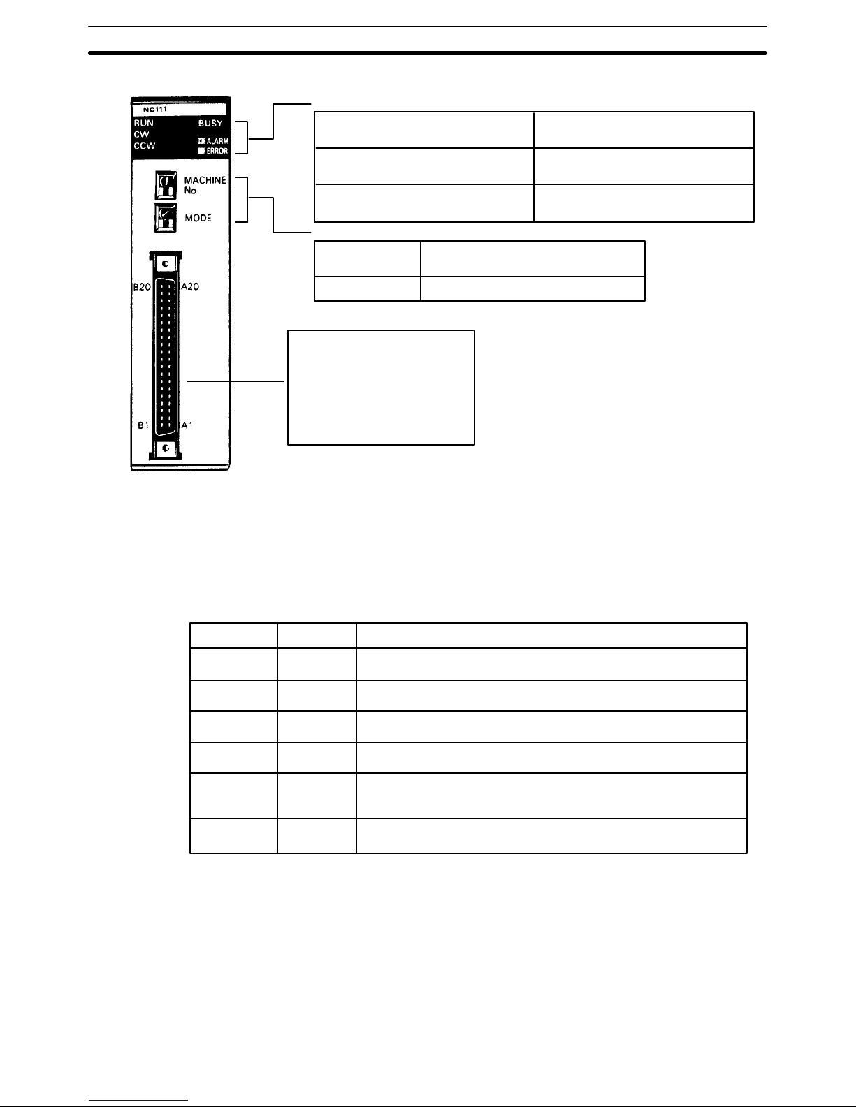
Indicators
RUN: indicates operation
is in progress
CW: indicates controlled system
(motor) is revolving clockwise
CCW: indicates controlled system
(motor) is revolving counterclockwise
BUSY: indicates operation/transfer
is in progress
ALARM: blinks when an abnormality
has occurred
ERROR: lights when an error has occurred
Setting switches
MACHINE No.
MODE
Allocates a unit number (0 to 9) to
the Position Control Unit
Not used
Connector
Used to connect the Position
Control Unit to a stepping motor driver or servomotor driver.
Attach the enclosed connector
to the proper cable.
When setting the switches, use a
screwdriver if necessary.
Do not apply an excessive force to the
switches.
Do not leave the switches halfway between two setting points or the Position
Control Unit may malfunction.
Before operating these switches, make
sure that power to the PC is off.
Indicators
Position Control Unit indicators (LEDs) are used to quickly determine operating status. They are particularly valuable in initial system activation and debugging, but can also be used to monitor and check Unit operation.
Indicator Color Function
Lit during normal operation. Goes out for errors.
Lit during output of CW (clockwise) pulses.
Lit during output of CCW (counterclockwise) pulses.
Lit during positioning or data transfer.
Flashing when a BCD error exists in initial data, speed
data, or positioning data updated with TRANSFER DATA.
Lit when an error has occurred causing operation to stop.
Green
Green
Green
Green
Red
Red
RUN
CW
CCW
BUSY
ALARM
(flashing)
ERROR
1–3 System Configuration
The basic system configuration is shown below. Position Control Unit outputs
are connected to a motor driver, either for a stepping motor or for a servomotor (either AC or DC) capable of receiving pulse train inputs. The Unit is
controlled by inputs from devices and/or a control panel. It, in turn, outputs
pulse trains and direction signals to control the motor driver.
System Configuration Section 1–3
Page 16

4
The motor driver controls either a stepping motor or a servomotor, depending
on whether an open-loop or semiclosed-loop system is employed. (See 1–4
Control System Principles). The stepping motor (or servomotor) controls
some type of positioning device (such as a feed screw, for example). An independent power supply must be used. Some configurations also require an
Input Unit on the C200H PC to control the motor driver.
Maximum Number of
Special I/O Units per PC
A maximum of 10 Special I/O Units, including Position Control Units,
High-Speed Counters, etc., can be mounted under the same PC, regardless
of whether they are on the CPU Rack, an Expansion I/O Rack, or a rack containing a Remote I/O Slave Unit controlled by the PC. No more than four of
these can be mounted onto any one rack containing a Remote I/O Slave
Unit.
Mounting Location
The Position Control Unit can be mounted to any but the 2 rightmost CPU
Rack slots. Mounting the Unit to either of these slots will prevent you from
mounting devices directly to the PC’s CPU. The back-panel DIP switch must
be set before the Unit is mounted. This switch is inaccessible on a mounted
Unit. (See 2–1 Switch Settings.)
Basic Configuration
Although Unit operation can be indirectly controlled from a host computer,
Remote I/O Master Unit, or other control system or peripheral device, direct
control comes from the program of the PC or from connections to external
inputs (e.g., control panel switches). (A list of Position Control Unit inputs and
outputs can be found under I/O Circuits in 2–2 Wiring.) The following configuration diagrams show only the positioning system itself. Refer to the operating manuals for other Omron control devices for details on extended control
system operation.
System Configuration Section 1–3
Page 17

5
Control signal input switches
C200H PC
Position Control Unit C200H-NC111
Input Unit
Stepping motor (or servomotor) driver control
signal line
Power supply
Hand-held Programming
Console C200H-PRO27
Stepping motor driver
(or servomotor driver)
Operation panel
Operation switch
Stepping motor
(or servomotor)
1–4 Control System Principles
Control systems can be quite simple or relatively complex. The most basic is
an open-loop system, in which a particular operation is carried out, according
to programmed instructions, but in which adjustments are not made directly
by the PC. Instead, the open-loop system typically displays or prints out information to assist a human operator in making any required adjustments. The
C200H-NC111 Position Control Unit can be used in an open-loop system in
conjunction with a stepping motor.
In a closed-loop system, on the other hand, the PC controls an external process without human intervention. The servomotor provides direct feedback so
that actual values (of positions, speeds, and so on) are continuously adjusted
Control System Principles Section 1–4
Page 18

6
to bring them more closely in line with target values. In some systems, the
digital feedback signals will be transmitted to a digital-to-analog converter to
complete the feedback loop, thereby permitting automated control of the
process.
A semiclosed-loop system is similar to a closed-loop system, except that
feedback is provided by a tachogenerator and a rotary encoder rather than
directly by the servomotor. If the C200H-NC111 Position Control Unit is used
with a servomotor, the servomotor driver must be able to handle digital signals, and there is no need for a D/A converter. In addition, the servomotor is
connected to a tachogenerator and a rotary encoder. The Unit can thus be
used in either an open-loop or a semiclosed-loop system.
Both open-loop and semiclosed-loop systems are described in more detail on
the following pages.
Control System Principles Section 1–4
Page 19
7
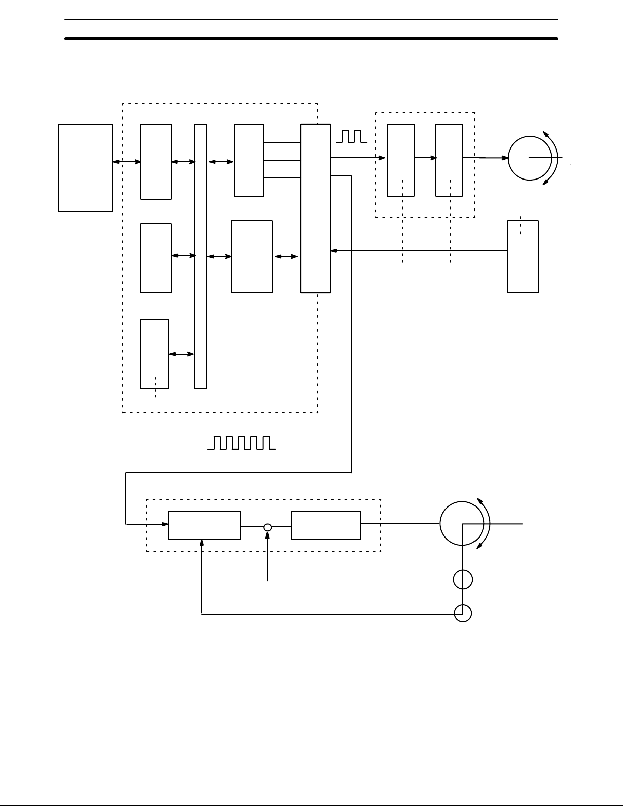
Data Flow
PC
BUS
I/F
C200H PC
Position Control Unit C200H-NC111
Rotary encoder
Tachogenerator
Servomotor driver
Pulse train
Power
amplifier
Pulse
train
Stepping motor driver
I/O
interface
MPU
Memory
Pulse
generator
Magnetizing
distribution
circuit
Servomotor
(Positioning output)
PC
BUS
I/F
External
input
Stepping motor
Error counter Power amplifier
I/O connector
1–4–1 Open-loop System
In an open-loop system, the Position Control Unit outputs pulse trains as
specified by the PC program to control the angle of rotation of the motor. Because the Unit outputs pulse trains, it is generally used with a stepping motor.
The angle of rotation of a stepping motor can be controlled through the number of pulse signals supplied to the motor driver. The number of rotations of
the stepping motor is proportional to the number of pulses supplied by the
Unit, and the rotational speed of the stepping motor is proportional to the
Control System Principles Section 1–4
Page 20
8
frequency of the pulse train.
Positioning pulse
1 2 n
Positioning output
Angle of
rotation
Angle of rotation
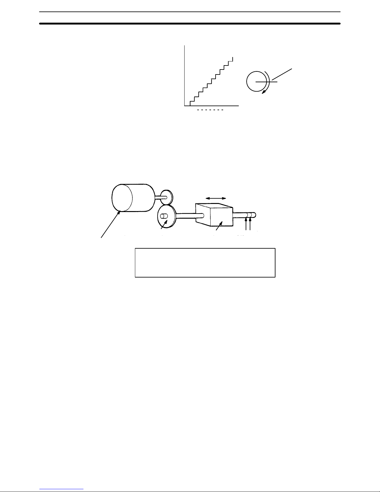
Simplified Positioning
System Design
The following diagram and parameters illustrate a simplified positioning system.
P
Stepping motor
Reduction gear
Object being
positioned
M: Reduction ratio
P: Feed screw pitch (mm/revolution)
V: Feed velocity of object being positioned (mm/s)
θs: Stepping angle per pulse (degree/pulse)
N
M
V
Feed screw pitch
The positioning accuracy in mm/pulse is computed as follows:
Positioning accuracy = P/(pulses per revolution x M)
= P/((360/S) x M))
= (P x S)/(360 x M)
The required pulse frequency from the Unit in pulses per second is computed
as follows:
Pulse frequency = V/Positioning accuracy
= (360 x M x V)/(P x S)
And the required number of pulses to feed an object by a distance L in mm is
computed as follows:
Number of pulses = L/Positioning accuracy
= (360 x M x L)/(P x S)
1–4–2 Semi-closed-loop System
When the Position Control Unit is used in a semiclosed-loop system, the system supplies feedback to compensate for any discrepancy between target
values and actual values in position or speed. This system detects motor ro-
Control System Principles Section 1–4
Page 21

9
tation amounts, for example, computes the error between the target value
and actual movement value, and zeroes the error through feedback. The diagram below illustrates the basic configuration of a semiclosed-loop system.
Rotary encoder
Tachogenerator
Servomotor driver
Servomotor
Position output
Error counter Power amplifier
Position feedback (feedback pulses)
Speed feedback
Target position
1) First, the target position is transmitted to the error counter in units of en-
coder pulses. The servomotor driver must be able to handle digital input.
2) The motor rotates at a speed corresponding to the speed voltage. The ro-
tary encoder connected to the motor axis rotates in sync with the motor, generates feedback pulses, and subtracts error counter contents.
3) Consequently, the encoder rotation is equivalent to the target position, and
the motor stops rotating when the error counter count and the speed voltage
become zero.
4) While the motor is stopped, the rotary encoder constantly maintains the
stopped position through correction. In the event that the motor axis slightly
moves, the error counter receives a feedback pulse from the rotary encoder,
whereby a rotation voltage is emitted in the reverse direction from which the
rotary encoder moved, causing the motor to rotate toward its original position. This operation is called servolock or servoclamp.
5) In order to execute positioning with acceleration and deceleration, target
positions are set consecutively in the error counter for processing.
6) The target position becomes the count for the error counter and controls
the motor by conversion to a speed voltage for the servomotor driver. The
position thus equals the total count of target positions and the speed will depend on the target position per unit time.
Control System Principles Section 1–4
Page 22

11
SECTION 2
Before Operation
Before the Position Control Unit can be operated, switch settings and wiring must be correct. This section presents the
settings and functions of switches, provides examples of and precautions for wiring, and gives dimensions of Units both
when mounted and unmounted. Be sure that all settings and wiring match your positioning system specifications.
2–1 Switch Settings 12. . . . . . . . . . . . . . . . . . . . . . . . . . . . . . . . . . . . . . . . . . . . . . . . . . . . . . . . . . .
2–2 Wiring 13. . . . . . . . . . . . . . . . . . . . . . . . . . . . . . . . . . . . . . . . . . . . . . . . . . . . . . . . . . . . . . . . . .
2–3 Dimensions 24. . . . . . . . . . . . . . . . . . . . . . . . . . . . . . . . . . . . . . . . . . . . . . . . . . . . . . . . . . . . . .
Page 23
12
2–1 Switch Settings
Always turn off PC power before setting the unit number switch. Use a regular screwdriver, being careful not to damage the slot in the screw. Be sure not
to leave the switch midway between settings.
Switch
Function
Used to set the unit number (between 0 and 9).
Do not set the same number for more than one Unit.
Doing so will cause an error and prevent operation.
Not used.
Unit number
(”Machine no.”)
Mode
Back Panel DIP Switch
These pins must be set before the Position Control Unit is mounted.
Pin no.
Name
Output pulse
selector
Origin search
direction
Origin proximity
present/absent
Origin proximity
signal type
Origin signal type
External interrupt
selection*
External interrupt
response*
Nondirectional pulse and
direction signal outputs.
CCW
Present
N.O. input
N.O. input
Fixed via pin #7
CHANGE SPEED
Not used.
Separate CW and
CCW pulse outputs
CW
Absent
N.C. input
N.C. input
Determined by
IR bit (word n, bit 06)
STOP
ON
OFF
1
2
3
4
5
6
7
8
*External interrupt processing is determined by pins #6 and #7 in combination with bit 06 of IR word n (n = 100 + 10 x unit
number). Refer to 4–10 External Interrupt Commands for details.
Switch Settings Section 2–1
Page 24
13
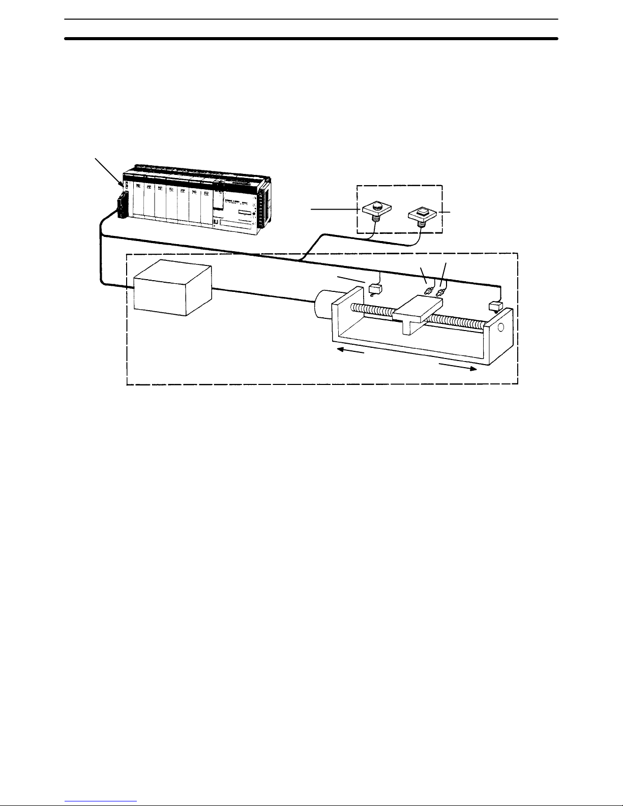
2–2 Wiring
External I/O Connections
The example diagram below shows I/O connections.
Position Control Unit
C200H-NC111
Output
C200H PC
Input
Motor
driver
Control panel
Emergency stop
switch
External interrupt
switch
CCW limit switch
Motor
Mechanical system
CW limit
switch
Origin switch (sensor)
CCW
CW
Origin proximity
switch
Wiring Section 2–2
Page 25

!
14
Connector Pin
Arrangement
The following I/O connector pin arrangement is as viewed from the front of
the Position Control Unit.
Emergency stop input (0 V) 20 Emergency stop input (12 to 24 VDC)
Emergency interrupt input (0 V) 19 External interrupt input (12 to 24 VDC)
18
17
16
15
14
CW limit input (0 V) 13 CW limit input (12 to 24 VDC)
CCW limit input (0 V) 12 CCW limit input (12 to 24 VDC)
Origin input (0 V) 11 Origin input (12 to 24 VDC)
Origin proximity input (0 V) 10 Origin proximity input (12 to 24 VDC)
9
8
7
6
Output power (0 V) 5 Output power (0 V)
CW pulse or nondirectional 4 CW pulse or nondirectional pulse output (1.6 k
Ω)
pulse output
CW pulse or direction signal output 3 CCW pulse or direction signal output (1.6 k
Ω)
5-VDC power supply input 2
1 24-VDC power supply input
Row B
Pin no.
Row A
External connector: FCN-361J040 (Fujitsu solder-type; included as an accessory.)
Caution Output power should be either 24 or 5 VDC. Never connect both the 24 and
5 VDC pins at the same time. In other words, never use power supplies of different voltages.
Wiring to Connectors
• Solder-type connectors are included with the Unit.
• Use wire with a cross-sectional area of 0.3 mm
2
or less.
• When soldering, do not short-circuit an adjacent terminal; cover the soldered section with an insulation.
• When using multi-core cable, wire output and input cables separately.
Wiring Section 2–2
Page 26
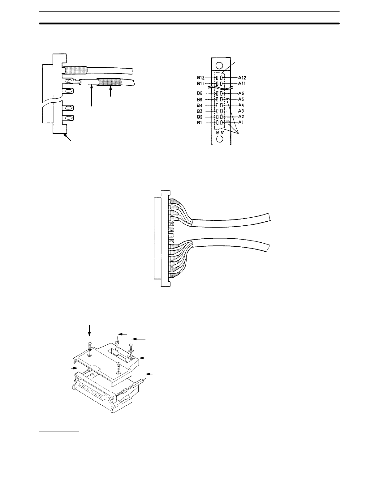
15
Insulator
Lead (0.3 mm
2
max.)
Connector
Connector Viewed from Soldered Side
Connector Pin Numbers
The connector pin numbers are shown in
the following figure. Wire the connector
correctly according to the pin numbers.
Shape of connector flange on other side
Pin number marks
Differentiating Cables
Output cables
Input cables
Assembling Connectors
Usable connectors:
Fujitsu model 360 jack
1. FCN-361J040-AU (solder)
FCN-360C040-B (connector cover)
2. FCN-363J040 (solderless)
FCN-363J-AU (contact)
FCN-360C040-B (connector cover)
3. FCN-367J040-AU/F (solderless)
1. is included as an accessory.
Two 8-mm M2 pan-head
screws (short)
Connector
(jack)
Four M2 nuts
Two 10-mm M2
pan-head screws (long)
Case
Lock screw
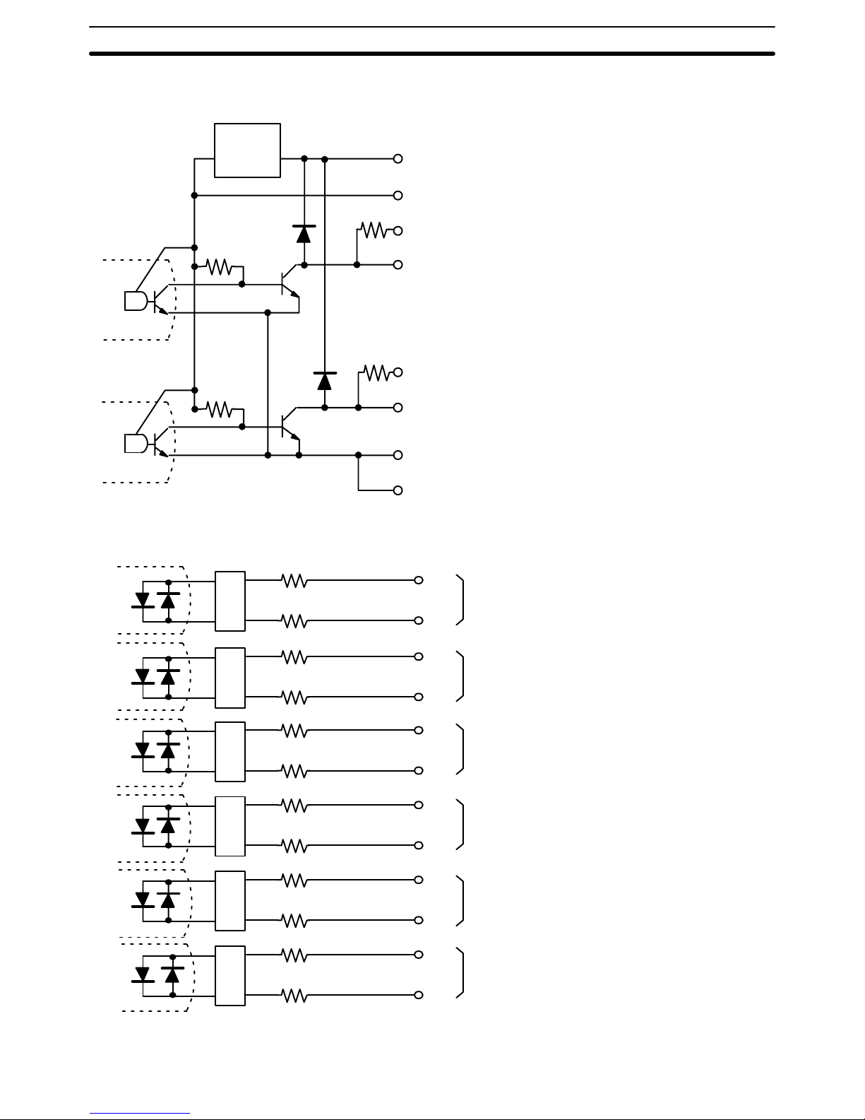
I/O Circuits
In the I/O circuits depicted in the following diagrams, pin numbers on the connector actually start from 1 at the bottom of the connector and run through 20
at the top.
Wiring Section 2–2
Page 27
16
Outputs
1.6 kΩ (1/2W)
Constantvoltage
circuit
A1
B2
1.6 k
Ω (1/2W)
A3
B3
A4
B4
A5
B5
Power for output, 24 VDC
Power for output, 5 VDC
CCW pulse output/direction output (w/1.6 k
Ω resistor)
CCW pulse output/direction output
Note: Either of the output signals is selected by
the DIP switch on the rear panel.
CW pulse output or nondirectional pulse output
(w/1.6 k
Ω resistor)
CW pulse output or nondirectional pulse output
0 V
0 V
Supply a voltage of either
5 or 24 VDC; the internal
circuit will be damaged if
both the power sources
are connected.
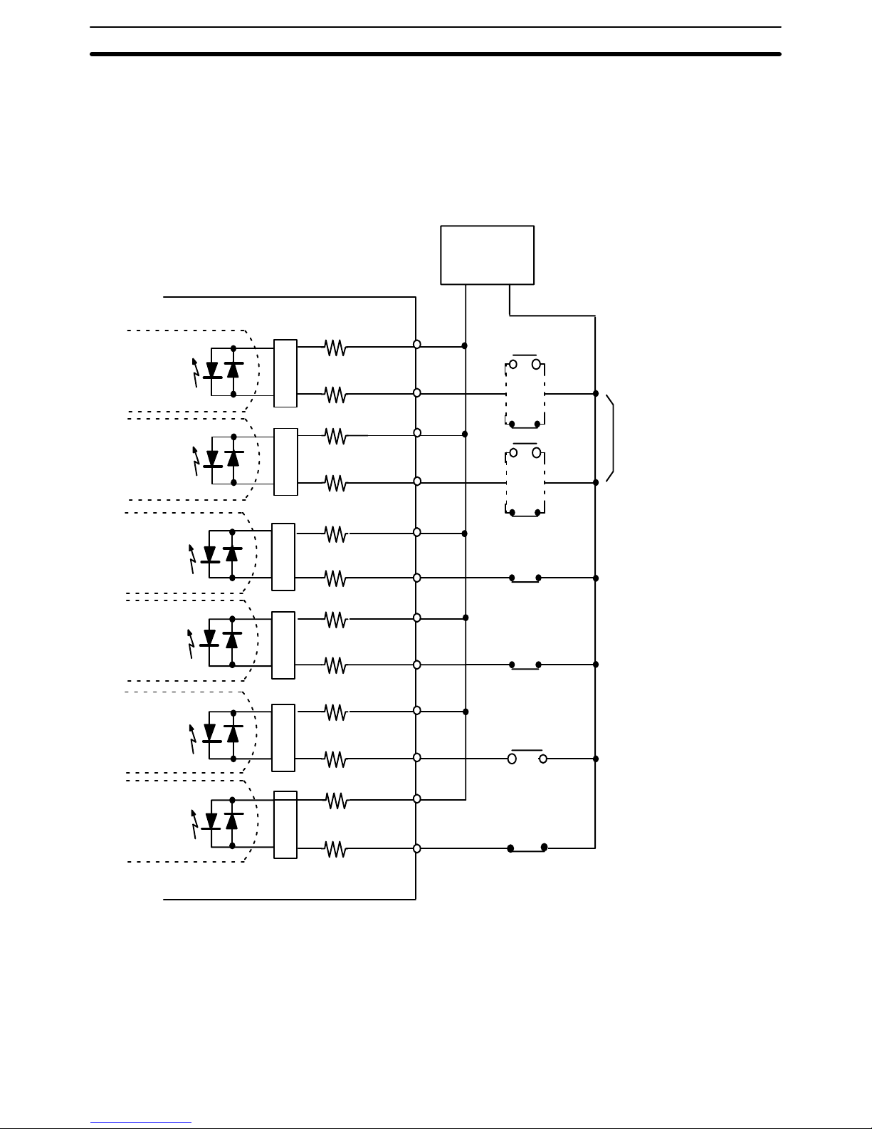
Inputs
1 kΩ
1 k
Ω
1 k
Ω
1 k
Ω
1 k
Ω
1 kΩ
1 k
Ω
1 kΩ
1 k
Ω
1 k
Ω
B11
A12
B12
A13
B13
A19
B19
A20
B20
CCW limit input
(NC input)
External interrupt input
(N.O. input)
Emergency stop input
(NC input)
(12 to 24 VDC)
(0 V)
(12 to 24 VDC)
(0 V)
(12 to 24 VDC)
(12 to 24 VDC)
(12 to 24 VDC)
(0 V)
(0 V)
(0 V)
1 kΩ
1 k
Ω
(12 to 24 VDC)
(0 V)
A10
B10
Origin proximity input
(Select either N.O. or N.C.
inputs via the back-panel
DIP switch.)
Origin input
(Select either N.O. or N.C.
inputs via the back-panel
DIP switch.)
CW limit input
(NC input)
A11
Wiring Section 2–2
Page 28
17
Input Connection
Example
Each input is provided with both a N.O. (normally open) input or N.C. (normally closed) input that can be used according to specifications.
Leave unused N.O. inputs open and connect unused N.C. inputs to the
power supply.
A10
B10
A12
B12
A13
B13
A19
B19
A20
B20
N.O. input
N.C. input
N.C. input
Position Control Unit
Origin proximity input
CCW limit input
CW limit input
External interrupt input
Emergency stop input
1 k
Ω
1 k
Ω
1 k
Ω
1 k
Ω
1 k
Ω
1 k
Ω
1 k
Ω
1 k
Ω
1 kΩ
1 k
Ω
+ –
N.C. input
A11
B11
Origin input
1 k
Ω
1 k
Ω
Power supply
(12 to 24 VDC)
Select either
N.O. or N.C.
inputs via the
back-panel
DIP switch.
• All inputs have independent grounds (commons) and are bidirectional. Connect switches of at least 12-mA capacity.
• Use a non-contact sensor (such as a proximity sensor) for the origin input to
reduce wear and deterioration.
Wiring Section 2–2
Page 29
!
18
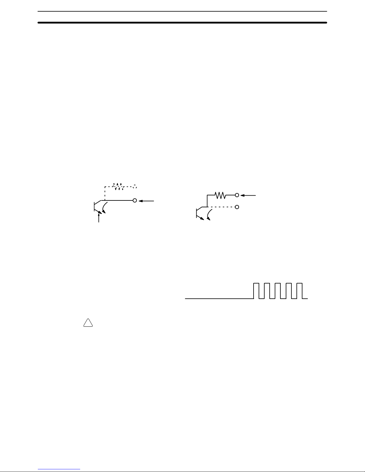
Output Connection
Examples
The following figures illustrate examples of connections to motor drivers. Always confirm motor driver specifications before making connections.
The Unit outputs only pulse trains and a direction output, or separate CW
and CCW pulse trains, to control the motor driver. If other control signals,
such as a deflection counter reset signal or motor excitation release signal,
are required, use a C200H I/O Unit and program in the required control actions.
Connect between 2.5-mA and 30-mA loads to outputs of the Unit, or add bypass resistance for loads less than 2.5 mA. Some output terminals have
1.6-kΩ (0.5 W) resistance built in. Use these as necessary according to
power supply and motor driver specifications. For voltage-level outputs, the
output goes low for ON and high for OFF.
Open collector output
Open collector output with 1.6 k
Ω series resistance
Output
2.5 to 30 mA
Output transistor
Output
2.5 to 30 mA
Pulses are not output when the output transistor in the pulse output section is
OFF. (For direction output, OFF indicates CCW.)
Output transistor
ON
OFF
Pulses are output
Caution Output power should be either 24 or 5 VDC. Never connect both the 24 and
5 VDC pins at the same time. In other words, never use power supplies of different voltages.
Wiring Section 2–2
Page 30
19
Example 1:
Outputting CW and CCW
Pulses With a 5-VDC
Power Supply
CCW input
CW input
Position Control Unit
24 VDC input
5 VDC input
CCW pulse output
CW pulse output
1.6 k
Ω
1.6 k
Ω
A1
B2
A3
B3
A4
B4
A5
B5
5-VDC
power
supply
+ –
Approx.
15 mA
Approx.
15 mA
Twisted pair cable
(+)
(–)
(+)
(–)
(Do not share this power supply with other pins.)
Motor driver (rated at 5 VDC)
(Example: R = 220
Ω)
Wiring Section 2–2
Page 31

20
Example 2:
Outputting CW and CCW Pulses With a 24-VDC Power Supply and a Motor Driver
Rated at 5 VDC
B4
(–)
(Example: R= 220Ω)
Position Control Unit
24-VDC input
5-VDC input
CCW pulse output
CW pulse output
1.6 k
Ω
1.6 kΩ
A1
B2
A3
B3
A4
A5
B5
24-VDC
power
supply
+ –
Approx.
12 mA
Approx.
12 mA
(Do not share this power source with other pins.)
Motor driver (rated at 5 VDC)
(+)
(–)
(+)
Twisted pair cable
Note In this example, a 5-V input motor driver is being used with a 24-V DC power
supply. The limit resistors (1.6 KΩ) of the NC111 are thus being used. Check
the driver current of the motor driver.
Example 3:
Outputting Pulse and Direction Signals with a 5-VDC Power Supply
Pulse (CW+CCW)
output
Pulse input
Position Control Unit
24-VDC input
5-VDC input
Direction output
1.6 k
Ω
1.6 k
Ω
A1
B2
A3
B3
A4
B4
A5
B5
5-VDC
power
supply
+
–
7 to 30 mA
7 to 30 mA
Motor driver (rated at 5 VDC)
Direction input
Wiring Section 2–2
Page 32

21
When the Position Control Unit is used to output voltage levels, the low level
is obtained when the output transistor turns ON, while the level goes high
when the transistor turns OFF.
Example 4:
Stepping–Motor Driver
Connection
Signal
24 V/0 V
B20
B13
B12
A12
B11
A10
B5
B2
A20
A13
A11
B4
+CW
+CCW
–CCW
E32
Stepping motor UPH599
Limit switch
(N.C. contact)
Position Control Unit
Power for
output
Origin
CCW
limit
CW limit
CW
CCW
0 V
B3
B10
+
5 VDC
+
Stepping motor driver Oriental UDX5114
Limit switch (N.O. or N.C. contact)
OMRON Photoelectric Switch
E3S-X3 CE4
(NPN output type)
–CW
Origin
proximity
Emergency
stop
24
VDC
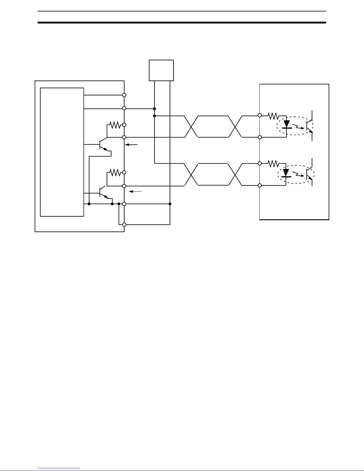
Example 5:
Servomotor Driver
Connection
When applying the servomotor driver Z-phase output to the origin input of the
Position Control Unit, the line input/open collector conversion circuit is re-
Wiring Section 2–2
Page 33

22
quired, as shown in the example diagram on the following page.
23
Signal
24 V/0 V
+
A20
B20
B13
A13
A12
B12
A10
B10
B5
A5
B2
CCW
B3
B4
5 V
24
N.C. switches
EM
Position Control Unit
Power for
output
CCW limit
CW limit
Emergency stop
CW
0 V
5 VDC
12 to 24 VDC
+
1
2
3
4
+CW
–CW
+CCW
14
OMRON R88M-E
Servomotor (marketed in Japan)
OMRON R88DEP06
Servomotor Driver (marketed in Japan)
RUN
33
22
–CCW
–
+
Z-phase output
A11
Origin proximity
Origin
B11
E32
+
12 to 24 VDC
Toshiba TLP521-1 (GB)
Photocoupler
50-75Ω
Limit switch
(N.O or N.C.)
N.C. limit
switches
OMRON E3S-X3 CE4
(NPN output)
Photoelectric switch
Wiring Precautions
Operational errors can occur in most electronic control devices if they are
subjected to electronic noise from nearby power lines or loads. Recovery
from such errors is usually very difficult and time-consuming. To avoid such
noise-originating operational errors and thus improve system reliability, always abide by the following precautions in wiring the system.
1, 2, 3... 1. Cables must be of the required diameter.
2. Power lines (e.g., AC power supply, motor power line) and control lines
(e.g., pulse output lines, external I/O signal lines) must be wired separately. Never put these lines into the same duct or make them into a single bundle.
3. Use shielded cable for control lines.
4. Attach a surge absorber to all inductive loads, such as relays, solenoids,
and solenoid valves.
Wiring Section 2–2
Page 34

23
+
DC
–
Diode for surge absorption AC Surge absorber
RYRY
DC relays AC relays
Note:
Connect the diode and surge absorber as close as possible to the relay. Use
a diode capable of withstanding a voltage five times higher than the circuit
voltage.
SOL Surge absorber
Solenoids
5. Insert a noise filter into the power supply inlet if noise enters the power
line (e.g., when it is connected to the same power supply as an electric
welder or an electric spark machine or when there is any source generating high frequency noise).
6. Twisted pair cable is recommended for power lines.
7. For grounds, use thick cable with a cross-sectional area of at least 1.25
mm
2
.
Wiring Section 2–2
Page 35

24
2–3 Dimensions
Unit Dimensions
(Unit: mm)
35
130
100.5
Mounted Dimensions
(Unit: mm)
Cable
Approx. 200
117
Rack
Dimensions Section 2–3
Page 36

25
SECTION 3
Operation
This section covers all aspects of Position Control Unit operation other than commands, which are covered in the following section. Included in this section are the basic operating procedure, the type of output pulses possible, the basic data
format and configuration, some special features to aid operation, such as flags, zone settings, backlash compensation and
internal limits, and the internal data calculation methods used in processing user-input data.
3–1 Operational Flow 26. . . . . . . . . . . . . . . . . . . . . . . . . . . . . . . . . . . . . . . . . . . . . . . . . . . . . . . . .
3–2 Output Pulses 28. . . . . . . . . . . . . . . . . . . . . . . . . . . . . . . . . . . . . . . . . . . . . . . . . . . . . . . . . . . .
3–3 Writing Data 28. . . . . . . . . . . . . . . . . . . . . . . . . . . . . . . . . . . . . . . . . . . . . . . . . . . . . . . . . . . . .
3–4 Data Configuration and Allocation 29. . . . . . . . . . . . . . . . . . . . . . . . . . . . . . . . . . . . . . . . . . .
3–5 IR Area Data Format 32. . . . . . . . . . . . . . . . . . . . . . . . . . . . . . . . . . . . . . . . . . . . . . . . . . . . . .
3–6 Flags and Other Input Data 33. . . . . . . . . . . . . . . . . . . . . . . . . . . . . . . . . . . . . . . . . . . . . . . . .
3–7 DM Area Allocation 33. . . . . . . . . . . . . . . . . . . . . . . . . . . . . . . . . . . . . . . . . . . . . . . . . . . . . . .
3–7–1 Zones 35. . . . . . . . . . . . . . . . . . . . . . . . . . . . . . . . . . . . . . . . . . . . . . . . . . . . . . . . . . .
3–7–2 Backlash Compensation 36. . . . . . . . . . . . . . . . . . . . . . . . . . . . . . . . . . . . . . . . . . . . .
3–7–3 Internal CW/CCW Limits 37. . . . . . . . . . . . . . . . . . . . . . . . . . . . . . . . . . . . . . . . . . .
3–7–4 Data Calculations 38. . . . . . . . . . . . . . . . . . . . . . . . . . . . . . . . . . . . . . . . . . . . . . . . . .
Page 37

26
3–1 Operational Flow
The basic procedure used to initially operate the Unit is outlined below. Refer
to applicable sections of the manual for details on each of these steps.
Item
Wiring
Data setting
Start
Wiring motor to
driver
Setting back-panel DIP switch
Data setting
Origin, origin proximity, CW/CCW
limits, emergency stop, external interrupt
.Output pulse selection
.Origin search direction
.Origin proximity signal type
.Origin signal type
.External interrupt signal type
DM area (key input via Programming Console)
.Parameters
.Positioning actions
.Speeds
Refer to:
Wiring external
inputs
Follow motor and driver and instruction
manuals for wiring details
Wiring Position Control
Unit to driver
2–2 Wiring
3–4 Data Configuration
2–1 Switch Settings
Section 4 Commands
3–7–4 Data Calculations
Section 5
Programming
Examples
Writing PC
program
Programming IR area (key input via
Programming Console)
Procedure
Operational Flow Section 3–1
Page 38

27
Item
ORIGIN SEARCH,
manual operation,
start, etc.
Correct error
Position Control
Unit reads DM area
Refer to:
Procedure
Restart by resetting
power or AR area
restart bit
Alarm/error
LED lit?
No
Yes
Error exists
READ ERROR
Alarm/error
LED flashes?
No
Yes
READ ERROR
Correct data
causing alarm
6–4 Troubleshooting
From the PC
AR area error and
restart bits for
Special I/O Units
4–5 READ ERROR
Section 6
Error
Processing
Trial run
Error processing
Operational Flow Section 3–1
Page 39

28
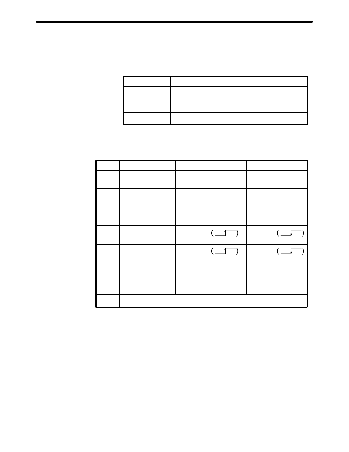
3–2 Output Pulses
The Position Control Unit can be set to output either independent CW and
CCW pulses or a nondirectional pulse and a direction signal. Set pin #1 on
the back-panel DIP switch to designate the target type of output. (See 2–1
Switch Settings.)
CW and CCW Pulse
Outputs
ON
OFF
CW pulse train
OFF
ON
CCW pulse train
Nondirectional Pulse
and Direction Signal
Outputs
Pulse train
Direction output
ON
OFF
ON
OFF
1 ms min.
CW: ON
CCW: OFF
CW
CCW
3–3 Writing Data
Data is written, via the Programming Console, into the section of the DM
area designated for Special I/O Units. The specific words are DM 1000-1999,
with 100 of these words allocated for each unit number assigned to a Position Control Unit. Written data is effective the next time power is turned on or
when the system is restarted with the restart bit in the AR area. To write data,
use the 3-word change operation of the Programming Console.
Key Input SequenceProgramming Console Display
D1824D1823D1822
0012 5000 2000
The above procedure prepares DM 1824 for change, and new data can be
keyed in. Pressing the CHG key again moves the cursor to DM 1823. After
inputting data, press the write key to execute the rewrite. In the above example, positioning action #0 of Unit #8 is shown.
Starting
When starting the Position Control Unit, the OUT refresh area is used. (The
OUT refresh area comprises the first five of the ten IR words allocated to
each Unit as refresh area. See 3–4 Data Configuration and Allocation for de-
Writing Data Section 3–3
Page 40

29
tails.) The busy flag and present position status can be read out from the IN
refresh area, the last five of these words.
To start the Unit, set (i.e., turn ON) the command bit regardless of whether
the Unit is in RUN or PROGRAM mode. Do not shift the mode between
MONITOR and PROGRAM while pulses are being output. Doing so will generate an error, preventing Unit operation.
Example: Starting Unit #8 in MONITOR or PROGRAM Mode
ST ART (command)
Start input
18000
In the above example, IR words 180 through 184 are allocated as the OUT
refresh area; IR words 185 through 190, as the IN refresh area.
Special I/O Unit
Restart Bits
AR Word 1
Restart bits can be used to transfer altered DM area data to the Unit without
turning power off and on. Refer to 6–3 Troubleshooting From the PC for re-
start bit allocations. The following Programming Console operation example
shows how to access the restart bit for Unit #0. The ladder diagram section
below it shows how to achieve the same operation through programming.
Programming Console Display Key Input Sequence
A0101
^ OFF
Program example: Unit #1
Restart switch
DIFU (13) AR0101
3–4 Data Configuration and Allocation
IR words 100 through 199 are allocated as I/O refresh areas. Each Position
Control Unit is allocated ten consecutive words. The first word for each Unit,
designated in this manual as n, can be computed from the unit number as
follows:
n = 100 + 10 x unit number.
Each Unit is also allocated 100 consecutive words as a fixed data area.
These words are in the DM area and run from DM 1000 through DM 1999.
The first word for each Unit, m, can also be computed from the unit number:
m = 1000 + 100 x unit number.
These allocations are shown below for all unit numbers. Details of allocations
within these words are given under the operations or commands to which
they apply. The tables on the following pages give a quick overview of word
and bit allocations. For a more complete overview, see Appendix C DM Area
Allocations and Appendix D IR Area Allocations.
Data Configuration and Allocation Section 3–4
Page 41

30
Data Configuration
C200H PC
IR Area
Words 100 to 109 Unit #0
Words 110 to 119 Unit #1
Words 120 to 129 Unit #2
Words 130 to 139 Unit #3
Words 140 to 149 Unit #4
Words 150 to 159 Unit #5
Words 160 to 169 Unit #6
Words 170 to 179 Unit #7
Words 180 to 189 Unit #8
Words 190 to 199 Unit #9
DM Area
Words 1000 to 1099 Unit #0
Words 1100 to 1199 Unit #1
Words 1200 to 1299 Unit #2
Words 1300 to 1399 Unit #3
Words 1400 to 1499 Unit #4
Words 1500 to 1599 Unit #5
Words 1600 to 1699 Unit #6
Words 1700 to 1799 Unit #7
Words 1800 to 1899 Unit #8
Words 1900 to 1999 Unit #9
Data is transferred
between the PC and
each Position Control
Unit each time I/O
data of the PC is refreshed.
Data is automatically transferred
from the PC to each Position Control Unit on power application or
when the AR area restart bit is
turned ON.
Position Control Unit
I/O refresh data areas
Words n to (n+4)
Words (n+5) to (n+9)
OUT refresh
IN refresh
Ten words are used
(n: 100 + 10 x unit no.)
Fixed data areas
Words m to m+21
Words m+22 to m+81
Words m+82 to m+97
Word m+98
Word m+99
Parameters
Position data
Speed data
Acceleration data
Deceleration data
100 words are used
(m: 1000 + 100 x unit no.)
Data Configuration and Allocation Section 3–4
Page 42

31
IR Area Allocations
”n” is the first IR word allocated to the Unit and equals 100 plus 10 times the
unit number.
00 START
01 Valid initial positioning
action number
02 ORIGIN SEARCH
03 ORIGIN RETURN
04 RELEASE PROHIBIT
05 READ ERROR
06 CHANGE SPEED
07 Valid speed coefficient
08 RESET ORIGIN
09 TEACH
10 TRANSFER DATA
11 HIGH-SPEED JOG
12 JOG direction
13 LOW SPEED JOG
14 INCH
15 STOP
Word n
Bit
n+1
Initial
positioning
action no.
Speed
coefficient
Beginning
word no.
(for TRANSFER DATA)
PC data area (for
TRANSFER DATA)
n+2 n+3 n+4
TEACH
positioning
action no.
00-19
Beginning
transfer no.
Number of
transfers (for
TRANSFER DATA)
TRANSFER
DATA type
(continued on next page)
Data Configuration and Allocation Section 3–4
Page 43

32
Emergency stop
signal
External
interrupt signal
Origin proximity
signal
00 Positioning completed
flag
01 Bank completed flag
02 At-origin flag
03 Alarm flag
04 Emergency stop flag
05 Error flag
06 Zone 0 flag
07 Zone 1 flag
08 Zone 2 flag
09 Teaching completed flag
10 Transfer completed flag
11 No-origin flag
12 Busy flag
13 CW limit flag
14 CCW limit flag
15 STOP flag
Word
Bit
n+6
n+7 n+8 n+9
Present
position
(rightmost 4
digits)
n+5
Origin signal
Output code
Positioning
action no.
Error
code
Direction digit
Present position
(leftmost 3 digits)
3–5 IR Area Data Format
Data is allocated either by bit or by word, though it is often input and output
by decimal digit, i.e., four bits (BCD). Position data is held in two adjacent
words, generally with a direction digit, in the following format.
direction
10310210110
0
10
4
10
5
10
6
0
1
CW
CCW
highest word
lowest word
Note that the rightmost word is always the lowest word. If the two words were
n+8 and n+9, for example, the rightmost word would be n+8 and the leftmost
would be n+9. Furthermore, the rightmost digit in each word begins in the
lowest bits. Thus, the digits x10
4
and x100 above would be held in bits 00
through 03 of their respective words. The direction digit also provides other
information when required.
Speeds, Acceleration,
and Deceleration
Only one word is used to store speeds, the acceleration, and the deceleration. The formats for these are as follows:
IR Area Data Format Section 3–5
Page 44

33
Speeds
10310210110
0
Acceleration and Deceleration
10210110
0
Data Coding
Although decimal notation is generally used for data in this manual, data is
handled in the system as binary-coded decimal (BCD) unless otherwise
noted. Note that this data is generally input as decimal, whereas hexadecimal data is input as hexadecimal. The number of digits given for certain data
refers to the decimal digits. For example, ”7 digits with direction” indicates
that the lowest word and rightmost 12 bits of the highest word are allocated
to the 7-digit decimal value; the leftmost four bits are allocated to the direction digit.
3–6 Flags and Other Input Data
IR words n+5 to n+9 are allocated to flags and other inputs that supply information about positioning system operation. Although some of these are described under specific operations or commands, they are presented together
in Appendix D IR Area Allocations for convenience. Of these, an output code
has been provided for user application and four signals, the last four in the
list, have been provided for system debugging.
3–7 DM Area Allocation
Coding Sheet
The table on the following page can serve as a general coding sheet for the
DM area. For a more detailed table describing the functions of all of the bits
in the DM area, see Appendix C DM Area Allocations.
The numbers shown for the DM words in the following table represent only
the final two digits of each word number. In other words, the first two digits
(which would be the same for all words) are not shown. The value of the first
two digits can be obtained by computing the first DM word allocated to the
Unit. This word, designated m, is equal to 1000 plus 100 times the unit number. Thus, for example, it would be 1000 for Unit #0, 1100 for Unit #1, and so
on.
DM Area Allocation Section 3–7
Page 45

34
00
01
02
03
04
05
06
07
08
09
10
11
12
13
14
15
16
17
18
19
20
21
22
23
24
25
26
27
28
29
30
31
32
33
15 00 Function W
Initial position nos.;
speed nos.
Origin compensation and direction
Backlash compensation
CW
limit
CCW
limit
Zone 0 CW limit
Zone 0 CCW limit
Zone 1 CW limit
Zone 1 CCW limit
Zone 2 CW limit
Zone 2 CCW limit
Not used
Positioning
action #0
0
Positioning
action #1
1
Positioning
action #2
2
Positioning
action #3
3
Transfer no.Transfer no.
15 00W Function
Positioning
action #4
4
Positioning
action #5
5
Positioning
action #6
6
Positioning
action #7
7
Positioning
action #8
8
Positioning
action #9
9
Positioning
action #10
10
Positioning
action #11
11
Positioning
action #12
12
Positioning
action #13
13
Positioning
action #14
14
34
35
36
37
38
39
40
41
42
43
44
45
46
47
48
49
50
51
52
53
54
55
56
57
58
59
60
61
62
63
64
65
66
67
68
69
70
71
72
73
74
75
76
77
78
79
80
81
82
83
84
85
86
87
88
89
90
91
92
93
94
95
96
97
98
99
W 15 00 Function
Positioning
action #15
15
Positioning
action #16
16
Positioning
action #17
17
Positioning
action #18
18
Positioning
action #19
19
Speed #1
Speed #2
Speed #3
Speed #4
Speed #5
Speed #6
Speed #7
Speed #8
Speed #9
Speed #10
Speed #11
Speed #12
Speed #13
Speed #14
Speed #15
Speed units
Acceleration
Deceleration
20
21
22
23
24
25
DM Area Allocation Section 3–7
Page 46

35
3–7–1 Zones
Up to three zones can be set in the DM area. If one or more zones have
been set, zone flags in the IR area can be used to determine if the present
position is within any established zones. A zone flag is ON (1) when the present position is within the zone; OFF (0) when it is not. Zones can be set to
cover a wide range of positions or narrowed to cover only part of a single positioning action. Zones can also be set to overlap, if target. For application
example, see programming example 8 in Section 5.
CW and CCW Limit
Settings
The CW and CCW limits for any one zone are set in separate word pairs, i.e.,
four words total are required to establish one zone. These words are allocated as follows:
Zone 0 CW limit: m+9 and m+10, 7 digits with direction
Zone 0 CCW limit: m+11 and m+12, 7 digits with direction
Zone 1 CW limit: m+13 and m+14, 7 digits with direction
Zone 1 CCW limit: m+15 and m+16, 7 digits with direction
Zone 2 CW limit: m+17 and m+18, 7 digits with direction
Zone 2 CCW limit: m+19 and m+20, 7 digits with direction
Note that the CW limit for any of the zones can be on the CCW side of the
origin; the CCW limit, on the CW side. In other words, a zone can either
cross the origin or be completely on one side of it. An alarm will be generated, however, if the CCW limit of a zone is set on the CW side of the CW
limit.
Zone 0 CW limit
CCW
Origin
CW
0
Zone 1 CCW limit
Zone 0 CCW limit
Inside zone
Inside zone
Zone 1 CW limit
Positioning axis
Example 1: Correct Setting
Zone 0 CCW limit
CCW
Origin
CW
0
Zone 0 CW limit
Positioning axis
Example 2: Incorrect Setting
DM Area Allocation Section 3–7
Page 47

36
Zone Flags
When the present position is in one or more of the zones, zone flags in the IR
area are turned ON (1). The PC’s scan time, however, can produce a delay in
indication during pulse output. Flag allocations are as follows:
0 Outside zone
1 Inside zone
08
n+5
0706
Zone 0 flag
Zone 1 flag
Zone 2 flag
3–7–2 Backlash Compensation
Backlash compensation can be used to compensate for the amount of mechanical play present in gears, particularly when the direction of positioning
actions changes.
Setting Parameters
There is only one parameter that needs to be set to compensate for backlash:
Backlash Compensation
DM word m+4
Set to between 0000 and 9999 pulses.
Backlash
DM Area Allocation Section 3–7
Page 48

37
Using Backlash
Compensation
When the feeding direction is reversed, the number of pulses set in DM area
is output at the initial speed, and the Unit then proceeds with normal operations.
Time
Compensation
If STOP is executed during backlash compensation for any operations requiring acceleration or deceleration (HIGH-SPEED JOG, ORIGIN SEARCH,
ORIGIN RETURN, and START), the Unit will stop feeding immediately after
outputting the initial step of the acceleration or deceleration, which will include the backlash compensation set above.
Stop position
Time
STOP executed
Compensation
3–7–3 Internal CW/CCW Limits
Limits on the CW and CCW sides of the origin can be set internally to restrict
Unit operation to within these limits.
CCW
Internally set value of CCW limit
0
Internally set value of CW limit
CW
Positioning axis
Internal CW Limit
DM words m+6 through m+5, 7 digits
Set to between 1 and 8388606.
Internal CCW Limit
DM words m+8 through m+7, 7 digits
Set to between 1 and 8388607.
The following values will be automatically set if the internal limit settings are
0.
CW: 8388607
CCW: 8388608
Operation
START (Positioning Actions)
DM Area Allocation Section 3–7
Page 49

38
If either of these limits is reached during execution of positioning actions,
pulse output will stop, and an error code, either 5030 or 5031, will be generated.
Manual Operation
If either of these limits is reached during execution of LOW-SPEED JOG,
HIGH-SPEED JOG, or INCH, pulse output will stop, and an error code, either
5070 or 5071, will be generated.
3–7–4 Data Calculations
Speeds
Slight differences exist between speeds set in the DM area and actual
speeds. These differences do not affect positioning accuracy.
Settings between 201
and 99,990 pps
where,
INT: Nearest integer
INT(4,000,000/set value): Divider ratio
pps: pulses per second
Actual speed (pps) =
4,000,000
INT(4,000,000/set value)
Pulse output (actual speed)
4 MHz
Divider
A 4-MHz source clock is divided by the integral divider ratio.
Example Values
Set Value (pps) Actual Speed (pps)
99,900 100,000.00
70,000 70,175.44
40,000 40,000.00
9,999 10,000.00
2,400 2,400.96
201 201.01
DM Area Allocation Section 3–7
Page 50

39
Settings between 1 and
200 pps
Actual speed (pps) =
62,500
INT(62,500/set value)
62.5 KHz
Pulse output (actual speed)
Divider
A 62.5-KHz source clock is divided by the integral divider ratio.
Example Values
Set Value (pps) Actual Speed (pps)
200 200.32
120 120.19
Trapezoidal Acceleration/Deceleration
An internal calculation process is used to create a trapezoidal figure from
speed, acceleration, and deceleration settings.
Speed
Time
When accelerating or decelerating between two speeds, the speed is varied
every unit time in a stepwise fashion. To achieve this, acceleration and deceleration tables are created internally when the Unit is first operated or when
TRANSFER DATA is used to alter data.
DM Area Allocation Section 3–7
Page 51

40
Table Creation
The internal processing of the Position Control Unit is as follows during table
creation.
1, 2, 3... 1. The speed difference, ∆V, is obtained to express the range of speed set-
tings.
∆
V = MAX – MIN
where,
MAX: Twice the maximum set value (not to exceed 100,000).
MIN: Speed indicated by initial speed number.
2. The number of division steps, L, is determined such that the unit time for
each step is 4 ms. The maximum number of steps is 250.
L = (∆V/R)
where,
R: Acceleration or deceleration data, whichever greater.
∆V/R: Acceleration (or deceleration) time between MAX and MIN
4
3. Next, the speed difference (∆υ) for each step is obtained.
∆υ
= (∆V/L)
4. The divider ratios for all steps are calculated and set in a table.
Step
Target (step) speed Division ratio
1 MIN
2 MIN +
∆υ
3 MIN + 2 x ∆υ
L MAX
5. Example
Start speed 0 (pps)
Maximum value of speed data Nos. 1 to 15 20000 (pps)
Acceleration 100 (pps/1ms)
Deceleration 100 (pps/1ms)
DM Area Allocation Section 3–7
Page 52

41
∆υ = 40000/100 = 400
∆V = 20000 x 2 = 40000
L = (∆V/R) = (40000/100) = 100
44
pps
40000
39600
39200
38800
20400
20000
19600
19200
1600
1200
800
400
4812
192
196
200
204 388 396
392 400
t (Time)
ms
υ (Speed)
400
4 ms
R = 400= 100
4
START Activation Time
The time required between START command bit recognition and the beginning of pulse output is 0.1 second or less.
Only about 10 ms is required to begin execution of positioning actions with
”single” positioning actions.
External Interrupt
Response Time
The time required between CHANGE SPEED or STOP command bit recognition and the beginning of execution is at least 10 ms.
Data Transfer Time
When executing TRANSFER DATA, the busy flag (bit 12 of word n + 5) will
be ON during data transfer and processing for the following time periods:
Positioning Action Data Only (positioning actions #0 through #19)
Maximum: 0.1 s + k (scan time)
When Speed Data (Transfers #20 through #25) Are Included
Maximum: 0.2 s + k (scan time)
DM Area Allocation Section 3–7
Page 53

42
The value of ”k” depends on the number of transfers being made, as illustrated in the following table.
Number of transfers k
1 to 6 1
7 to 13 2
14 to 20 3
21 to 26 4
Influence on
PC Scan Time
Mounting one Position Control Unit on a PC extends the PC’s scan time by
about 3 ms. In addition, when transferring data, the scan time during which
data is transferred increases by another 5 ms. For example, to transfer all 20
positioning actions, TRANSFER DATA only needs to be executed once, but
both the PC and Position Control Unit require 3 scans. Each of these 3 scan
times will be 5 ms longer than the normal scan time.
DM Area Allocation Section 3–7
Page 54

43
SECTION 4
Commands
The Positioning Control Unit provides thirteen commands to execute automatic and manual positioning actions, define
and establish position, transfer data, and handle interrupts and errors. Although the data required for execution is listed
under each command, much of this data is used by more than one command. Refer to 3–4 Data Configuration and Allo-
cation for an outline of the structure of Unit data, and to 3–5 IR Area Data Format for format specifications for particular
types of data. Appendix C DM Area Allocations and Appendix D IR Area Allocations also provide convenient overviews
of data allocation. Applications of most commands are presented in Section 5 Programming Examples.
4–1 Start 44. . . . . . . . . . . . . . . . . . . . . . . . . . . . . . . . . . . . . . . . . . . . . . . . . . . . . . . . . . . . . . . . . . .
4–1–1 DM Area Settings 44. . . . . . . . . . . . . . . . . . . . . . . . . . . . . . . . . . . . . . . . . . . . . . . . .
4–1–2 IR Area settings 49. . . . . . . . . . . . . . . . . . . . . . . . . . . . . . . . . . . . . . . . . . . . . . . . . . .
4–1–3 Execution Examples 51. . . . . . . . . . . . . . . . . . . . . . . . . . . . . . . . . . . . . . . . . . . . . . .
4–2 Origin Search 55. . . . . . . . . . . . . . . . . . . . . . . . . . . . . . . . . . . . . . . . . . . . . . . . . . . . . . . . . . . .
4–2–1 DM Area Settings 55. . . . . . . . . . . . . . . . . . . . . . . . . . . . . . . . . . . . . . . . . . . . . . . . .
4–2–2 IR Area Settings 56. . . . . . . . . . . . . . . . . . . . . . . . . . . . . . . . . . . . . . . . . . . . . . . . . . .
4–2–3 Execution Examples 57. . . . . . . . . . . . . . . . . . . . . . . . . . . . . . . . . . . . . . . . . . . . . . .
4–2–4 Completion Examples 60. . . . . . . . . . . . . . . . . . . . . . . . . . . . . . . . . . . . . . . . . . . . . .
4–3 Origin Return 63. . . . . . . . . . . . . . . . . . . . . . . . . . . . . . . . . . . . . . . . . . . . . . . . . . . . . . . . . . . .
4–3–1 DM Area Settings 63. . . . . . . . . . . . . . . . . . . . . . . . . . . . . . . . . . . . . . . . . . . . . . . . .
4–3–2 IR Area Settings 64. . . . . . . . . . . . . . . . . . . . . . . . . . . . . . . . . . . . . . . . . . . . . . . . . . .
4–3–3 Execution Example 64. . . . . . . . . . . . . . . . . . . . . . . . . . . . . . . . . . . . . . . . . . . . . . . .
4–4 Release Prohibit 65. . . . . . . . . . . . . . . . . . . . . . . . . . . . . . . . . . . . . . . . . . . . . . . . . . . . . . . . . .
4–4–1 Execution Examples 66. . . . . . . . . . . . . . . . . . . . . . . . . . . . . . . . . . . . . . . . . . . . . . .
4–5 Read Error 68. . . . . . . . . . . . . . . . . . . . . . . . . . . . . . . . . . . . . . . . . . . . . . . . . . . . . . . . . . . . . .
4–5–1 Execution Example 68. . . . . . . . . . . . . . . . . . . . . . . . . . . . . . . . . . . . . . . . . . . . . . . .
4–5–2 Reading from the Programming Console 69. . . . . . . . . . . . . . . . . . . . . . . . . . . . . . .
4–6 Reset Origin 69. . . . . . . . . . . . . . . . . . . . . . . . . . . . . . . . . . . . . . . . . . . . . . . . . . . . . . . . . . . . .
4–7 Teach 69. . . . . . . . . . . . . . . . . . . . . . . . . . . . . . . . . . . . . . . . . . . . . . . . . . . . . . . . . . . . . . . . . .
4–7–1 IR Area Settings 70. . . . . . . . . . . . . . . . . . . . . . . . . . . . . . . . . . . . . . . . . . . . . . . . . . .
4–7–2 Execution Example 71. . . . . . . . . . . . . . . . . . . . . . . . . . . . . . . . . . . . . . . . . . . . . . . .
4–7–3 Teaching from the Programming Console 71. . . . . . . . . . . . . . . . . . . . . . . . . . . . . . .
4–8 Transfer Data 71. . . . . . . . . . . . . . . . . . . . . . . . . . . . . . . . . . . . . . . . . . . . . . . . . . . . . . . . . . . .
4–8–1 Normal Transfer 72. . . . . . . . . . . . . . . . . . . . . . . . . . . . . . . . . . . . . . . . . . . . . . . . . . .
4–8–2 IR Area Settings 73. . . . . . . . . . . . . . . . . . . . . . . . . . . . . . . . . . . . . . . . . . . . . . . . . . .
4–8–3 Present Position Preset 75. . . . . . . . . . . . . . . . . . . . . . . . . . . . . . . . . . . . . . . . . . . . . .
4–9 Manual Operations 78. . . . . . . . . . . . . . . . . . . . . . . . . . . . . . . . . . . . . . . . . . . . . . . . . . . . . . . .
4–9–1 DM Area Settings 78. . . . . . . . . . . . . . . . . . . . . . . . . . . . . . . . . . . . . . . . . . . . . . . . .
4–9–2 IR Area Settings 79. . . . . . . . . . . . . . . . . . . . . . . . . . . . . . . . . . . . . . . . . . . . . . . . . . .
4–9–3 High-speed Jog 80. . . . . . . . . . . . . . . . . . . . . . . . . . . . . . . . . . . . . . . . . . . . . . . . . . .
4–9–4 Low-speed Jog 80. . . . . . . . . . . . . . . . . . . . . . . . . . . . . . . . . . . . . . . . . . . . . . . . . . . .
4–9–5 Inch 81. . . . . . . . . . . . . . . . . . . . . . . . . . . . . . . . . . . . . . . . . . . . . . . . . . . . . . . . . . . .
4–10 External Interrupt Commands 81. . . . . . . . . . . . . . . . . . . . . . . . . . . . . . . . . . . . . . . . . . . . . . .
4–10–1 Stop 82. . . . . . . . . . . . . . . . . . . . . . . . . . . . . . . . . . . . . . . . . . . . . . . . . . . . . . . . . . . .
4–10–2 Change Speed 89. . . . . . . . . . . . . . . . . . . . . . . . . . . . . . . . . . . . . . . . . . . . . . . . . . . .
Page 55

44
4–1 Start
The START command bit, bit 00 of word n, is set to begin execution of positioning actions (effective on signal’s rising edge). The actions are executed in
order from either the initial positioning action designated in the DM area or
that designated in the IR area. Positioning actions are executed in order until
a ”single” or ”bank end” positioning action is reached, at which time START is
again required in order to begin execution of positioning actions.
When a bank end positioning action is reached or when positioning action
#19 has been performed, the initial positioning action designated in the DM
area is performed next. The valid initial positioning action and completion
codes (i.e., single, pause, continuous, bank end, and extended) are described later in this subsection.
4–1–1 DM Area Settings
Bits 1000 to 1999 of the DM area of the PC are used as data storage areas
for the Position Control Unit, storing data such as initial positioning action
numbers, initial speed numbers, speed data, acceleration/deceleration data,
position data, completion codes, dwell times, and output codes. (Refer to 3–4
Data Configuration and Allocation for details.)
Initial Positioning Action
Number
DM word m, bits 07-00
Set to a value between 00 and 19. This number is used at:
• Initial START after turning on the Unit (if bit 01 of word n is 0)
• START after bank ends
• START after completion of positioning action #19
If bit 01 of word n is 1, the initial positioning action number designated in the
IR area is used for the initial START after turning on the Unit, allowing for a
different starting point for positioning system initialization.
x101x10
0
m
(m = 1000 + 100 x unit number)
11 08 07 00
Initial positioning action number
Initial speed number
Initial Speed Number
DM word m, bits 11-08
Set to a value between 0 and F (hex). An initial speed number of 0 indicates
a speed of 0. All the other speed numbers set here refer to the speeds set in
DM words m+82 through m+96.
Start Section 4–1
Page 56

45
Acceleration
Acceleration
Time
Target speed Target speed
Initial speed #0 Initial speed number
other than 0
Speeds
DM words m+82 through m+96
Set each word to a value between 0000 and 9999 pps (4 digits)
Each of these values, when multiplied by the relevant speed unit in word
m+97, is referred to by number to set speeds for this and several other commands.
15 00
m+82
to
m+96
m+97
Bit number
x10
3
x10
3
15 00
x10
2
x10
2
x10
1
x10
1
x10
0
x10
0
Speed No. 1
to
Speed No. 15
Set speeds in BCD from
0000 to 9999.
0
Speed Units
DM word m+97
Each of the bits in this word is assigned to one of the speeds set in words
m+82 through m+96. If the bit is set to 0, the speed is multiplied by 1; if the
bit is set to 1, then the speed is multiplied by, by 10. Bit assignments are as
follows:
Bit 00 is not used. Bit 01 is assigned to speed #1, bit 02 to speed #2, bit 03 to
speed #3, and so on, up to bit 15.
Acceleration
DM word m+98, bits 11-00, 3 digits
Acceleration is in pps per ms.
Deceleration
DM word m+99, bits 11-00, 3 digits
Deceleration is in pps per ms.
Positioning Actions
DM words m+22 through m+81
Start Section 4–1
Page 57

46
Positioning actions (or sequences) consist of a completion code, dwell time,
output code, speed number, and target position. These actions are generally
referred to by number and completion code. For example, ”#6, continuous”
indicates positioning action #6 with a completion code of 2 (continuous). The
settings for positioning action #0, DM words m+22 through m+24, are explained below. The same procedure is followed for any other positioning action. See Appendix C DM Area Allocations for detailed word and bit allocations.
Completion Code
DM word m+22, bits 03-00
Set to between 0 and 4 to specify the five types of completions (described
below). See also 4–1–3 Execution Examples.
m+22
03 to 00
Completion code: 0 to 4
0: Single
The target position and target speed are reached and feeding stops. After
completion of this action, START is necessary in order to to execute the next
positioning action(s).
Initial speed
Acceleration
Target speed
Deceleration
Stop from initial speed
Target position
Time
START
1: Pause
The target position and target speed are reached, and the next positioning
action is automatically started following the dwell time.
Target speed
Dwell time
Start of next positioning action
Time
START Pause
Start Section 4–1
Page 58

47
2: Continuous
As soon as the target position for the first positioning action is reached, the
next positioning action is started. The first target position is reached at the
target speed set for the next positioning action, so that the next positioning
action can be executed immediately.
Time
Target position for first
positioning action
Target speed for first
positioning action
START
Target speed for next positioning action
3: Bank end
The term ”bank” refers to a combination of several positioning actions or sequences. The target position and target speed are reached and feeding
stops. The next positioning action to be executed will be the initial positioning
action number in bits 07-00 of DM word m. START is required in order to resume execution of positioning actions.
Target speed
Stop
Time
START
4: Extended
The Unit continually outputs pulses at the speed set for the positioning action. The Unit will not calculate the present position, and the no-origin flag (bit
11 of word n+5) will go ON during operation. The direction of pulse output is
determined by the direction digit set in the positioning data. (See Appendix C
DM Area Allocations.) Extended positioning actions are terminated with
STOP. START is required in order to resume execution of positioning actions.
Stop
Time
STOP executed
START
Target speed
Dwell Time
DM word m+22, bits 07-04
Set to a value between 0 and F (hex). (Unit: 0.1 s)
Start Section 4–1
Page 59

48
The next action can be executed when the busy flag turns OFF after the
dwell time has expired. In other words, the positioning completed flag remains OFF and the busy flag remains ON until the dwell time has expired.
(See 4–1–3 Execution Examples.)
Output Code
DM word m+22, bits 11-08
Set to an integer between 0-F (hex).
These codes can be set as target by the user. Upon completion of the posi-
tioning action, they are output to word n+7 bits 11-08, of the OUT refresh
area.
m+22
15 to12 11 to 08
Positioning action
number
n+7
x10
1
x10
0
11 to 08 07 to 00
Output code: 0 to F (hexadecimal)
(Output to word n+7, bits 11 to 08.)
Target speed number: 1
to F (hexadecimal)
Target Speed Number
DM word m+22, bits 15-12
Set to a value between 1 and F (hex).
The speed number set here refers to the speeds set in DM words m+82
through m+96.
Target Position
DM words m+23 through m+24
The target position is set with the lowest seven digits, i.e., all four digits of
word 23 and the lowest three digits of word 24. The remaining digit of word
Start Section 4–1
Page 60

49
24 is used as a direction digit. (See Appendix C DM Area Allocations.)
m+24
15 00
m+23
x10
3
x102 x10
1
x10
1
x10
0
Sign
x10
6
x10
5
x10
4
m+24 m+23
Direction
x10
6
x10
5
x10
4
x10
3
x10
1
x10
0
CW absolute value
CCW absolute value
CW increment
CCW increment
0
1
2
3
Maximum values are as follows:
CW: 8388606 pulses
CCW: 8388607 pulses
Absolute values are measured from the origin. Increment values are measured from the present position. Positions resulting from increments must be
between –8,388,607 and +8,388,606.
8388607
CCW
(Origin)
0
CCW direction
increment value
Present
position
CW direction
increment
value
8388606
Absolute
value
CW
Note that the TEACH command can be used to write target positions into the
DM area. See 4–7 TEACH for details.
4–1–2 IR Area settings
In C200H PCs, IR words 100 to 199 are used for Special I/O Units. When a
Position Control Unit is used, they are allocated as I/O refresh areas. For a
detailed explanation, see 3–4 Data Configuration and Allocation. For a detailed table of words and bits in the IR area, see Appendix D IR Area Alloca-
Start Section 4–1
Page 61

50
tions.
n
15 07 0100
START
Valid initial positioning action number
V alid speed coefficient
STOP
START
word n, bit 00
When bit 00 is ON (i.e., set at 1), bits 01 and 07 are referred to and position-
ing begins.
Valid Initial Positioning
Action Number
word n, bit 01
This is used when the initial positioning number is designated in the I/O re-
fresh areas. After the initial position is set with bits 07 to 00 of word n+1, the
START command is set with this bit These values are set within the same
scan.
1: Initial position number set in bits 07-00 of IR word n+1 is
valid.
0: Initial position number set in bits 07-00 of DM word m is
valid.
Valid Speed Coefficient
word n, bit 07
This is used when the target speed of the positioning action is multiplied by a
coefficient . After the speed coefficient is set with bits 07 to 00 of word n+2,
the START command is set with this bit. These values are set within the
same scan. This bit can function simultaneously with bit 01 (described
above).
1: Coefficient in bits 07-00 of word n+2 is valid.
0: Coefficient is 1.0.
Deceleration/Stop
Command (STOP)
word n, bit 15
This bit turns ON when STOP is executed during pulse output. Pulse output
cannot be executed as long as this bit remains ON. See 4–10–1 STOP for a
more detailed explanation and several STOP execution examples.
Initial Positioning Action
Number
word n+1, bits 07-00
Set to an integer between 00 and 19.
START will be executed from the positioning action number specified here if
bit 01 of word n is 1 when the START command bit (bit 00 of word n) is set.
Start Section 4–1
Page 62

51
Speed Coefficient
word n+2, bits 07-00
Set a value between 00 and 20 (in units of 0.1). In other words, a setting of
15, for example, will represent an actual value of 1.5.
This coefficient is valid if bit 07 of word n is 1 when the START command bit
(bit 00 of word n) is set. It is valid only during START and cannot be changed
during an operation.
The speed coefficient represents the coefficient with regard to the target
speed. If the value is set at 00, the speed will be considered to be 100 and a
coefficient of 1.0 will be used. If the value is set anywhere from 01 to 20, the
set value will be multiplied by 0.1 to determine the coefficient. The speed coefficient can thus be set in increments anywhere from 0.1 to 2.0.
If the speed resulting from the coefficient exceeds 100 kpps or falls below 1
kpps, the speed will be set at 100 kpps or 1 kpps, respectively. Speed coefficients will have no effect on accelerations and decelerations.
Speed
Coefficient: of 1.5
Coefficient: of 0.5
Acceleration
Time
Target speed (coefficient
not used or set at 1.0)
4–1–3 Execution Examples
Example 1: Using
Completion Codes
In example diagram on the following page, the initial position and the target
position at bank end are the same and the valid initial positioning action number is 0. Positioning actions in these and all following diagrams are indicated
simply by their numbers.
Start Section 4–1
Page 63

52
CCW
Initial position
CW
positioning axis
START
START
START
START
#0
#1
#2 #3
#4
#6
#5
Pause
The completion code for positioning action #0 is set at 0, making it a single
action. Positioning stops after completion of this action, and START is necessary for operation to begin again.
The completion codes for positioning actions #1 and #2 are set at 2, making
them continuous actions. Positioning actions #1, #2, and #3 are thus executed consecutively, with each action reaching its target position at the target
speed set for the subsequent action. The completion code for positioning action #3 is set at 0, making it a single action and causing positioning to stop
after completion of this sequence of actions.
The completion code for positioning action #4 is set at 1, making it a pause
action. Upon completion of this action, there will be a pause (set as dwell
time); following the pause, the next positioning action will start automatically.
Positioning actions #4 and #5 are thus executed consecutively, with a preset
pause in between. Since the completion code for positioning action #5 is set
at 1 (single), positioning will stop after completion of this sequence.
The completion code for positioning action #6 is set at 3, making it a bank
end. Completion of this action will thereby signal completion of the entire
bank of actions. Upon completion of this action, the Unit will be prepared to
execute positioning action #0 but will wait for START before beginning.
Refer to the more detailed example diagrams on the following page.
Start Section 4–1
Page 64

53
Stop
Completion code
m+22
m+25
m+28
m+31
m+34
m+37
m+40
Positioning
action #0
0
2
2
0
1
0
3
Pause
Single
Bank end
Pulse output
CW
CCW
Pulse output
CW
CCW
Pulse output
CW
CCW
Automatic start
Time
Time
Time
Single
Continuous
Continuous
Stop
Stop
Pulse output
CW
CCW
Time
Single
Positioning
action #1
Positioning
action #2
Positioning
action #3
Positioning
action #4
Positioning
action #5
Positioning
action #6
#0
#1
#2
#3
#4
#5
#6
START
START
Pause
START
START
Stop, wait for #0 START
Start Section 4–1
Page 65

54
Example 2:
Using Dwell Time
In this example, the completion code for positioning action #1 is set at 1
(pause), with the dwell time set at 0.5 s. The completion code for positioning
action #2 is set at 0 (single), with the dwell time set at 1.0 s.
Pulse output
1
0
1
0
1
0
0.5 s 1.0 s
Time
#1
#2
START
(word n, bit 00)
Positioning completed
flag (word n+5, bit 00)
Busy flag
(word n+5, bit 12)
Example 3: Using START
With Single or Bank End
Positioning Actions
Positioning sequences combining several pause and/or continuous positioning actions normally are ended by a single or bank end positioning action.
When the last positioning action is completed, including any dwell time designated for it, the positioning completed flag turns ON and busy flag turns OFF.
START is then required to begin further execution of positioning actions.
START is also required to restart operation after the STOP command has
been executed. (See 4–10 External Interrupt Commands for details and examples.)
Start Section 4–1
Page 66

55
ST ART command
word n, bit 00
Pulse output
Time
1
0
1
0
1
0
When positioning ends, the positioning
action number is changed as follows:
2103
Output
code of
action #0 action #1 action #2
code of code of
Output Output
#0, single
#1, continuous
#2, single
Positioning completed flag
word n+5, bit 00
Busy flag
word n+5, bit 12
Positioning action number
word n+7, bits 07-00
Output code
word n+7, bits 08-11
4–2 Origin Search
The ORIGIN SEARCH command bit, bit 02 of word n, is set to establish the
position of the origin through inputs from an origin sensor and, if provided, an
origin proximity sensor (effective on signal’s rising edge). Before using ORIGIN SEARCH, set the DIP switch as described in 2–1 Switch Settings to establish the direction from which the search will be made, the presence or absence of a proximity sensor, and the type of input used.
4–2–1 DM Area Settings
In addition to the settings described in detail in this section, the data listed
below must also be set in order to execute ORIGIN SEARCH. They are the
same as those set for START, so they can be set by following the instructions
contained in 4–1 START.
Initial Speed Number Bits 11-08 of DM word m
SpeedsDM words m+82 through m+96
Speed Units DM word m+97
Acceleration Bits 11-00 of DM word m+98
Deceleration Bits 11-00 of DM word m+99
Origin Search Section 4–2
Page 67

56
ORIGIN SEARCH
Proximity Speed Number
(Low Speed)
DM word m+1, bits 03-00
Set to an integer between 1-F (hex). The speed number set here refers to
one of the speeds set in DM words m+82 through m+96. It cannot be set
higher than the ORIGIN SEARCH high speed number. If there is no origin
proximity signal, the speed designated here is used for the entire ORIGIN
SEARCH operation.
ORIGIN SEARCH
High Speed Number
DM word m+1, bits 07-04
Set to an integer between 1-F (hex). The speed number set here refers to
one of the speeds set in DM words m+82 through m+96. The speed designated here is used only if an origin proximity signal is present.
Origin Compensation
DM words m+2 and m+3
Set word m+2 to a value between 0000 and 9999 pulses.
Set bit 00 of word m+3 to set the direction of compensation:
0: CW
1: CCW
If the position determined by origin signal input is to be treated as the origin
(position 0), set word m+2 to 0. Otherwise set the value and direction necessary to obtain the required origin. If there is an origin compensation value set
in word m+2, then, after reaching the position determined by origin signal
input, compensation will be executed at proximity speed in the direction set
at bit 00 of word m+3. See the example given below and 4–2–3 Execution
Examples for application.
In the example diagram below, bit 00 of word m+3 is set at 1, so origin compensation is counterclockwise.
Proximity signal
Origin signal
Pulse output
CCW
Deceleration
Search direction: CCW
Acceleration
Initial speed
positioning axis
Compensation
CW
ORIGIN SEARCH high speed
0.5 s pause
Proximity speed
Proximity speed
4–2–2 IR Area Settings
In C200H PCs, IR words 100 to 199 are used for Special I/O Units. When a
Position Control Unit is used, they are allocated as I/O refresh areas. For a
detailed explanation, see 3–4 Data Configuration and Allocation. For a detailed table of words and bits in the IR area, see Appendix D IR Area Alloca-
tions.
Origin Search Section 4–2
Page 68

57
In the IR area, the ORIGIN SEARCH command is set with bit 02 of word n.
ORIGIN SEARCH begins when this bit is turned ON.
n
02
(n = 100 + 10 x unit number)
ORIGIN SEARCH command bit
(ORIGIN SEARCH is started at the leading edge of
this bit.)
4–2–3 Execution Examples
Search Patterns With
Origin Proximity Signal
There are basically three possible search patterns when an origin proximity
signal is present (i.e., when DIP switch no. 3 is ON). The pattern executed
depends on the position of the origin with respect to the starting position and
search direction. N.O. inputs are used in the following example diagrams.
Example 1
The first diagram illustrates the simplest search pattern, i.e., that in which
both the origin proximity and origin signal activation points are in the search
direction from the initial position.
Origin proximity signal
1
0
1
0
Origin signal
Deceleration
Proximity speed
Origin (Stop)
Search direction (CCW)
CCW
CW
Positioning axis
ORIGIN SEARCH (Begin)
High speed
Acceleration
Initial speed
Example 2
When beginning ORIGIN SEARCH from inside the activation points for the
origin proximity signal, the Unit first feeds beyond the activation point, and
Origin Search Section 4–2
Page 69

58
then begins searching in the search direction.
Origin proximity signal
1
0
1
0
Origin signal
Proximity speed
Origin (Stop)
Search direction (CCW)
CCW
CW
Positioning axis
ORIGIN SEARCH (Begin)
Example 3
When reaching the CW or CCW limit during ORIGIN SEARCH, the Unit
pauses for 0.5 s, returns beyond the activation point for the origin proximity
signal, and then begins searching in the search direction.
Origin proximity signal
1
0
1
0
Origin signal
Proximity speed
Origin (Stop)
Search direction (CCW)
CCW
CW
Positioning axis
ORIGIN SEARCH (Begin)
Deceleration
Deceleration
Acceleration
Acceleration
CW limit
High speed
0.5 s
Search Patterns Without
Origin Proximity Signal
When an origin proximity signal is not present, only the ORIGIN SEARCH
proximity speed is used for ORIGIN SEARCH. This affects the three search
Origin Search Section 4–2
Page 70

59
patterns only by eliminating accelerations and decelerations. All other aspects remain the same.
Example 1
The first diagram illustrates the simplest search pattern, as in Example 1
above.
Origin signal
1
0
Proximity speed
Search direction (CCW)
ORIGIN SEARCH (Begin)Origin (Stop)
Positioning axis
CWCCW
Example 2
As in Example 2 on the previous page, when beginning ORIGIN SEARCH
from inside the activation points for the origin proximity signal, the Unit first
feeds beyond the activation point, and then begins searching in the search
direction.
1
0
Origin signal
CCW
ORIGIN SEARCH (Begin)
Origin (Stop)
Search direction (CCW)
CW
Positioning axis
Example 3
As in Example 3 on the previous page, when reaching the CW or CCW limit
during ORIGIN SEARCH, the Unit pauses for 0.5 s, returns beyond the activation point for the origin proximity signal, and then begins searching in the
search direction.
Origin signal
1
0
CCW CW
Positioning axis
0.5 s
Search direction (CCW)
CCW limit
ORIGIN SEARCH (Begin)
Origin (Stop)
Origin Search Section 4–2
Page 71

60
4–2–4 Completion Examples
Completion Patterns
With an Origin Proximity
Signal
The following two example diagrams both illustrate completion of ORIGIN
SEARCH when an origin proximity signal is present (i.e., when DIP switch
no. 3 is ON). There is an origin compensation value set in the second example, but not in the first.
Example 1: Without
Origin Compensation
Origin proximity signal
Origin signal
Pulse output
1
0
1
0
High speed
Deceleration
Proximity speed
Time
At-origin flag
word n+5, bit 02
No-origin flag
word n+5, bit 11
Busy flag
word n+5, bit 12
1
0
1
0
1
0
Origin Search Section 4–2
Page 72

61
Example 2: With Origin
Compensation
Proximity speed
0
1
0
1
0
High speed
Deceleration
0.5 s
Movement equivalent to compensation
value
Time
1
0
1
0
1
Origin proximity signal
Origin signal
Pulse output
At-origin flag
word n+5, bit 02
No-origin flag
word n+5, bit 11
Busy flag
word n+5, bit 12
Origin Search Section 4–2
Page 73

62
Completion Patterns
Without an Origin
Proximity Signal
The following two example diagrams both illustrate completion of ORIGIN
SEARCH when no origin proximity signal is present (i.e., when DIP switch
no. 3 is OFF). There is an origin compensation value set in the second example, but not in the first.
Example 1: Without
Origin Compensation
1
0
Proximity speed
Time
1
0
1
0
1
0
Origin signal
Pulse output
At-origin flag
word n+5, bit 02
No-origin flag
word n+5, bit 11
Busy flag
word n+5, bit 12
Origin Search Section 4–2
Page 74

63
Example 2: With Origin
Compensation
Proximity speed
0
1
0
0.5 s
Movement equivalent to compensation value
Time
1
0
1
0
1
Origin signal
Pulse output
At-origin flag
word n+5, bit 02
No-origin flag
word n+5, bit 11
Busy flag
word n+5, bit 12
4–3 Origin Return
The ORIGIN RETURN command bit, bit 03 of IR word n, is set to return to
the origin (effective on signal’s rising edge). Because origin and origin proximity signals are not used, the present position relative to the origin must be
known. ORIGIN SEARCH or TRANSFER DATA (to preset the present position) must therefore be used to establish position before ORIGIN RETURN is
executed.
4–3–1 DM Area Settings
In addition to the ORIGIN RETURN speed number (described below), the
following data must also be set in order to execute ORIGIN RETURN. They
are the same as those set for START, so they can be set by following the instructions contained in 4–1 START.
Initial Speed Number Bits 11-08 of DM word m
SpeedsDM words m+82 through m+96
Speed Units DM word m+97
Acceleration Bits 11-00 of DM word m+98
Deceleration Bits 11-00 of DM word m+99
ORIGIN RETURN Speed
Number
DM word m, bits 15-12
Set from 1 to F (hexadecimal).
Origin Return Section 4–3
Page 75

64
4–3–2 IR Area Settings
The ORIGIN RETURN command is valid when bit 03 of word n is ON.
n
03
(n = 100 + 10 x unit number)
ORIGIN SEARCH command
ORIGIN SEARCH is started at the leading edge of this bit..
4–3–3 Execution Example
ORIGIN RETURN can only be executed when the origin (0) is known. As
shown in this example diagram, acceleration and deceleration automatically
form a trapezoidal pattern, stopping at the origin.
0
Pulse output
1
0
Initial speed
ORIGIN RETURN (Begin)
ORIGIN RETURN speed
Acceleration
Deceleration
Initial speed
Time
[IN refresh data area flags]
1
0
1
ORIGIN RETURN
word n, bit 03
At-origin flag
word n+5, bit 02
Busy flag
word n+5, bit 12
Origin (Stop)
Origin Return Section 4–3
Page 76

65
4–4 Release Prohibit
When Position Control Unit operation is stopped as a result of input of an
emergency stop, CW limit, or CCW limit signal, (i.e., when the N.C. input of
any of these turns ON), further pulse output is prohibited. In order to resume
pulse output, it is necessary to cancel this prohibition by means of the RELEASE PROHIBIT command bit (bit 04 of word n) and release of the external
emergency stop switch.
External input pin no.
20
13
12
A
B
A
B
A
B
CCW
Emergency stop
CCW limit CW limit
CW
Positioning axis
Power sourc
e
0 V
24 V
Release Prohibit Section 4–4
Page 77

66
4–4–1 Execution Examples
Example 1:
Emergency Stop
The present position is lost during an emergency stop, and positioning cannot be started again directly after RELEASE PROHIBIT. Execute ORIGIN
SEARCH before proceeding.
0
1
0
1
0
1
0
1
0
1
0
1
0
1
Input
6000
Time
Emergency stop signal
START
word n, bit 00
RELEASE PROHIBIT
word n, bit 04
Pulse output
Emergency stop flag
word n+5, bit 04
Error flag
word n+5, bit 05
No-origin flag
word n+5, bit 11
Busy flag
word n+5, bit 12
Alarm/error code
word n+6
ORIGIN SEARCH
word n, bit 02
1
0
0000
ORIGIN SEARCH (Begin)
Turned OFF upon completion
of ORIGIN SEARCH.
Release Prohibit Section 4–4
Page 78

67
Example 2: Exceeding
CW or CCW Limit
The emergency stop flag is not affected by exceeding the CW or CCW limit.
When a limit is exceeded, only pulse output in the opposite direction is possible. In other words, when the CW limit is exceeded, only CCW pulse output is
possible. Although a CCW HIGH-SPEED JOG is used to clear the CW limit
flag in the example, LOW-SPEED JOG or ORIGIN SEARCH may also be
used.
0
1
0
1
0
1
0
1
0
1
CCW
1
0
1
0
1
0
1
0
6100
Time
CW
CW limit signal
START
word n, bit 00
RELEASE PROHIBIT
word n, bit 04
HIGH-SPEED JOG
word n, bit 11
JOG direction
word n, bit 12
Pulse output
Error flag
word n+5, bit 05
No-origin flag
word n+5, bit 11
Busy flag
word n+5, bit 12
CW limit flag
word n+5, bit 13
Alarm/error code
word n+6
Release Prohibit Section 4–4
Page 79

68
4–5 Read Error
The READ ERROR command bit, bit 05 of word n, is set to access error and
alarm codes when more than one of these is present (effective on signal’s
rising edge). The codes are consecutively output to word n+6. Errors and
alarms have separate flags, as follows:
15 00
Alarm flag: Set to 1 when an alarm code has been
generated
Error flag: Set to 1 when an error has occurred
Error code (or alarm code)
n+5
03
05
x10
3
x102 x101 x10
0
n+6
word n+6 shows four digits in BCD when displayed on the Programming
Console. If there are no errors or alarms, 0000 will be displayed. If there are
any errors or alarms, they will be displayed in code. The codes will be displayed in order as READ ERROR is executed. (If there is only one code,
however, the display will not change when READ ERROR is executed.)
The error or alarm code (word n+6) is updated via I/O refreshing immediately
after the READ ERROR command bit is turned ON. The busy flag does not
turn ON. READ ERROR can be used within a signal scan.
For further information and details, refer to Section 6 Error Processing. For a
complete list of alarm codes, refer to Appendix A Alarm Code List.
4–5–1 Execution Example
The following diagram shows an example in which first the alarm code 1501
and then the error code 5000 are displayed.
1
0
1
0
1
0
Display will not change
because only one alarm
code has been generated.
1501
First alarm code
Display has been
changed because
another error code
has been generated.
5000
Second error code
Display has been
changed because an
error code has been
read.
1501
First alarm code
READ ERROR
word n, bit 05
Alarm flag
word n+5, bit 03
Error flag
word n+5, bit 05
Alarm/error code
word n+6
Read Error Section 4–5
Page 80

69
4–5–2 Reading from the Programming Console
The following example diagram (for Unit #1) shows how to read an alarm/error code from the Programming Console.
Key sequence:Programming Console Display:
C106
1501
10005 C106
^OFF 1501
10005 C106
^OFF 5000
4–6 Reset Origin
The RESET ORIGIN command bit, bit 08 of word n, is set to redefine the present position as the origin (effective on signal’s rising edge).
Execution Example
1
0
1
0
1
0
1
0
Busy for 1 scan time
Present position changed to 0
RESET ORIGIN
word n, bit 08
At-origin flag
word n+5, bit 02
No-origin flag
word n+5, bit 11
Busy flag
word n+5, bit 12
Present position
word n+8 and n+9
4–7 Teach
When the origin and present position are defined (i.e., when the no-origin flag
is OFF), you can use TEACH to write the present position as fixed data into
the C200H PC’s DM area available for use by Special I/O Units. The TEACH
command bit, bit 09 of word n, is set to write the present position as the target position for the designated positioning action. Data is set as absolute positions, and not as increments. TEACH can be executed within a single scan.
The following diagram uses Unit #10 as an example.
Teach Section 4–7
Page 81

70
Present
position
DM 1052
DM 1053
DM 1054
CCW
positioning axis
0
CW
Data set using TEACH is valid immediately and can be used for positioning
actions without turning off the power or transferring data. Note that data rewritten using the Programming Console is not valid until data has been transferred again.
4–7–1 IR Area Settings
In C200H PCs, IR words 100 to 199 are used for Special I/O Units. When a
Position Control Unit is used, they are allocated as I/O refresh areas. For a
detailed explanation, see 3–4 Data Configuration and Allocation. For a detailed table of words and bits in the IR area, see Appendix D IR Area Alloca-
tions.
Present Position
When the no-origin flag is OFF, and pulse output is stopped at the position to
be taught, the present position is set in words n+8 and n+9.
TEACH Positioning
Action Number
word n+1, bits 15-08
Set an integer between 00 and 19. The number set here indicates the posi-
tioning action under START for which the present position is to be set as the
target position.
TEACH Command Bit
word n, bit 09
TEACH is executed when this bit is ON.
Teach Section 4–7
Page 82

71
4–7–2 Execution Example
1
0
1
0
1
0
TEACH positioning action no.
word n+1, bits 15-08
TEACH
word n, bit 09
Teaching completed flag
word n+5, bit 09
Busy flag
word n+5, bit 12
4 scans max.
4–7–3 Teaching from the Programming Console
The following example shows how to teach positions from the Programming
Console for Unit #0. It assumes that ORIGIN SEARCH has been executed,
and writes the present position into words DM 1053 and DM 1054 as an absolute position (i.e., relative to the origin).
Programming Console Display
Key sequence
10013
^ OFF
10013
^ ON
C101 10013
0000 ^ OFF
C101 10013
1000 ^ OFF
10013 C101
^ OFF 1000
10009 C101
^ OFF 1000
10009 C101
^ OFF 1000
Teaching Position Number
(Teaching ON/OFF)
4–8 Transfer Data
Use TRANSFER DATA when the set data automatically transferred from the
C200H PC to the Position Control Unit is insufficient. Although only the data
from the area designated for any particular Unit is automatically transferred,
TRANSFER DATA can be used to access data from any data area in the PC
In other words (as described in 3–4 Data Configuration and Allocation), Posi-
tion Control Units are consecutively allocated 100 words each from the DM
Transfer Data Section 4–8
Page 83

72
area, and this data is automatically transferred. TRANSFER DATA, however,
can transfer data from other parts of the DM area as well as from the LR, HR,
and other areas.
C200H PC
DM 1500 to 1599
I/O memory
Automatically transferred at
start-up or restart via AR area
restart bit.
Position Control Unit #5
Data table
Parameters
Positioning
actions
Speeds
Acceleration
Deceleration
TRANSFER
DATA
IR area,
LR area,
HR area,
etc.
TRANSFER DATA can be executed either to rewrite positioning data set in
the Unit or to change the present position to any target position. The type of
transfer is determined by the following setting.
TRANSFER DATA type
IR word n+2, bit 15
1: Preset position
0: Normal transfer
If this bit is 0, then bits 15 through 08 of word n+2 determine the beginning
transfer number, as explained below. (Bit 15 of word n+2 will always be 0
when a beginning transfer number is designated. When this bit is set to 1,
bits 14 through 08 are ignored and only the present position is affected.) This
command can be executed within a single scan.
4–8–1 Normal Transfer
If bit 15 of word n+2 is 0, the TRANSFER DATA command bit, bit 10 of word
n, is set to transfer the positioning actions, speeds, acceleration, and deceleration from a data area of the PC other than the one allocated to the Position Control Unit. Any data area in the C200H PC may be designated. This
data is directly transferred from the designated area to memory within the
Unit; the data set for the Unit in the allocated section of DM area is not af-
Transfer Data Section 4–8
Page 84

73
fected. Parameters set in DM words m through m+21 are not changed when
TRANSFER DATA is executed.
Data Preparation
Up to 26 transfers (three words each) can be made each time TRANSFER
DATA is executed. Each transfer consists of one positioning action, three
speeds, or the speed units, acceleration, and deceleration. In any case, three
words are required for each transfer. This data must be prepared in a PC
data area in the required format and in consecutive words. (See Appendix C
DM Area Allocations for the content of each word/bit.)
Positioning action #0
Positioning action #1
Positioning action #19
Speed #1
Speed #2
Speed #3
Speed #4
Speed #5
Speed #6
Speed #13
Speed #14
Speed #15
Speed units
Acceleration
Deceleration
Data Area
DM area
DM area ( for
Special I/O Units)
I/O area
LR area
HR area
AR area
Words
0000 to 0999
1000 to 1999
000 to 255
000 to 63
00 to 99
00 to 27
Transfer #0
Transfer #1
Transfer #19
Transfer #20
Transfer #21
Transfer #24
Transfer #25
PC Data Areas Available for TRANSFER DATA
Position Control Unit’s Rewritten Data
4–8–2 IR Area Settings
In C200H PCs, IR words 100 to 199 are used for Special I/O Units. When a
Position Control Unit is used, they are allocated as I/O refresh areas. For a
detailed explanation, see 3–4 Data Configuration and Allocation. For a detailed table of words and bits in the IR area, see Appendix D IR Area Alloca-
tions.
Transfer Data Section 4–8
Page 85

74
Beginning Transfer Number
word n+2, bits 15-08
Set an integer between 00 and 25.
This number indicates the position where the first transfer is to be made. The
designated number of transfers will be transferred continuously from this
point.
See Appendix C DM Area Allocations for the words transferred with each
transfer number.
Beginning Word
Number
word n+3, bits 15-00
This is the first word in the PC data area that is to be transferred into the Po-
sition Control Unit beginning at the transfer number designated above. The
beginning word and ending word (computed from the number of transfers)
must be within one of the data areas designated during data preparation.
(See Data Preparation under 4–8–1 Normal Transfer.)
PC Data Area
word n+4, bits 07-00
Set the data area (in four digits BCD) from which the transfer is to be made.
15 00
Data Area
00
01
02
03
04
n+3
n+4
n+4 n+3
x10
3
x102 x101 x100 x101 x100 x101 x100
DM
I/O
LR
HR
AR
Beginning word number
Set a word
number in
4-digit BCD
code
Number of transfers
Number of Transfers
word n+4, bits 15-08
Set an integer between 01 and 26.
TRANSFER DATA
Command Bit
word n, bit 10
After the above settings are made, TRANSFER DATA is executed with this
bit. This can all be done in one scan.
Transfer Data Section 4–8
Page 86

75
Execution Example
(Normal Transfer)
This example assumes that bit 15 of word n+2 is 0.
Set necessary information in IR area.
1
0
1
0
1
0
Data transfer Data processing
Preparation of data
in PC’s data areas
Beginning transfer number
word n+2, bits 15-08
Beginning word number
word n+3
PC data area/no. of transfers
word n+4
TRANSFER DATA
word n, bit 10
Transfer completed flag
word n+5, bit 10
Busy flag
word n+5, bit 12
4–8–3 Present Position Preset
If bit 15 of word n+2 is 1, the TRANSFER DATA command bit, bit 10 of word
n, is set to either preset or change the present position. This command can
be used to eliminate the need to execute ORIGIN SEARCH to establish position. Since the origin, present position, and so on, are not known when the
Unit is powered up, it is ordinarily necessary to execute ORIGIN SEARCH
first. However, when you want to know the absolute position and set a particular numerical value, you can use the preset function.
Retaining Present
Position
No data is retained in the Position Control Unit once power is turned OFF.
When the present position needs to be retained, copy it (words n+8 and n+9)
Transfer Data Section 4–8
Page 87

76
to either the HR or DM area, and then restore by using TRANSFER DATA
the next time the Unit is powered up.
The following programming example shows word n+8 data moving to word
HR 00 and word n+9 data moving to word HR 01. If there is no origin, bit 11
of word n+5 (the no-origin flag) turns ON (goes to 1). As long as there is an
origin and the present position data is valid, the present position will be transferred.
0 CW
1 CCW
n+8
n+9
15 00
x10
3
x102 x101 x100
x10
6
x105 x104
n+9 n+8
x10
3
x102 x101 x100 x106 x105 x104
XFER (70)
#0002
n+8
HR 00
x10
3
x102 x101 x100
x10
6
x105 x104
Sign
HR 00
HR 01
n+5, bit 11
Direction
Direction
Data Preparation
Data must be prepared in the same manner as for normal execution of
TRANSFER DATA, except that only two words indicating the target position
are necessary.
Present Position
Preset Bit
word n+2, bit 15
Set this bit to 1 in order to use the preset function. If this bit is set to 0, the
beginning transfer number is set in bits 15-08 as described in Beginning
Word Number under 4–8–2 IR Area Settings.
Beginning word
Number
word n+3, bits 15-00
This number indicates the first of the two words to be transferred in as the
present position. The two words must be within one of the data areas designated for Data Preparation toward the beginning of 4–8–1 Normal Transfer.
Transfer Data Section 4–8
Page 88

77
PC Data Area
word n+4, bits 07-00
Set the data area (in four digits BCD) from which the transfer is to be made.
Data Area
00
01
02
03
04
n+3
n+4
15 00
n+4 n+3
x10
3
x102 x101 x100 x101 x100 x101 x100
DM
I/O
LR
HR
AR
Beginning word number
Set a word
number in
4-digit BCD
code
Number of transfers
TRANSFER DATA
Command Bit
word n, bit 10
After the above settings are made, TRANSFER DATA is executed with this
bit. This can all be done in one scan.
Transfer Data Section 4–8
Page 89

78
Execution Example
(Preset)
The following example assumes that bit 15 of word n+2 has been set to 1.
Set necessary information in IR area.
1
0
1
0
1
0
Data transfer
Present position preset
word n+2, bit 15
Beginning word number
word n+3
PC data area
word n+4 bits 07-00
TRANSFER DATA
word n, bit 10
Transfer completed flag
word n+5, bit 10
Busy flag
word n+5, bit 12
Present position
words n+8 and n+9
This position is reflected in the IN refresh area
Present position determined
Preset value
4–9 Manual Operations
There are three manual feeding commands: HIGH-SPEED JOG,
LOW-SPEED JOG and INCH. Acceleration and deceleration are possible
with HIGH-SPEED JOG, but not with LOW-SPEED JOG. INCH operates one
pulse at a time.
4–9–1 DM Area Settings
In addition to the settings described in this section, the following data must
also be set in order to execute HIGH-SPEED JOG. They are the same as
those set for START, so they can be set by following the instructions contained in 4–1 START. Only the first three of these need be set for
LOW-SPEED JOG.
Initial Speed Number Bits 11-08 of DM word m
Manual Operations Section 4–9
Page 90

79
SpeedsDM words m+82 through m+96
Speed Units DM word m+97
Acceleration Bits 11-00 of DM word m+98
Deceleration Bits 11-00 of DM word m+99
HIGH-SPEED JOG Speed
Number
word m+1, bits 15-12
Set an integer between 1 and F (hex).
The speed number set here refers to one of the speeds set in DM words
m+82 through m+96.
LOW-SPEED JOG
Speed Number
word m+1, bits 11-08
Set an integer between 1 and F (hex).
The speed number set here refers to one of the speeds set in DM words
m+82 through m+96.
4–9–2 IR Area Settings
In C200H PCs, IR words 100 to 199 are used for Special I/O Units. When a
Position Control Unit is used, they are allocated as I/O refresh areas. For a
detailed explanation, see 3–4 Data Configuration and Allocation. For a detailed table of words and bits in the IR area, see Appendix D IR Area Alloca-
tions.
HIGH-SPEED JOG
Command
word n, bit 11
0: Stop
1: Operate
JOG Direction
word n, bit 12:
0: CW
1: CCW
LOW-SPEED JOG
Command
word n, bit 13
0: Stop
1: Operate
INCH Command
word n, bit 14
0: Stop
1: Operate
Manual Operations Section 4–9
Page 91

80
4–9–3 High-speed Jog
The HIGH-SPEED JOG command bit (word n, bit 11) of is set to manually
feed at the designated speed (effective on signal’s rising edge). Feeding
starts when the command bit is set and continues until it is reset.
1
0
1
0
Initial speed
HIGH-SPEED JOG speed
Acceleration
Deceleration
Initial speed
Time
HIGH-SPEED JOG
word n, bit 11
Pulse output
Busy flag
word n+5, bit 12
End position (stop)
Initial position (start)
4–9–4 Low-speed Jog
The LOW-SPEED JOG command bit, bit 13 of word n, is set to manually feed
at the designated speed (effective on signal’s rising edge). Feeding starts
when the command bit is set and continues until it is reset.
1
0
1
0
Time
LOW-SPEED JOG
word n, bit 13
Pulse output
Busy flag
word 12, bit n+5
LOW-SPEED JOG speed
Initial position (start) End position (stop)
Manual Operations Section 4–9
Page 92

81
4–9–5 Inch
The INCH command bit, bit 14 of word n, is set to manually inch one pulse at
a time (effective on signal’s rising edge). One pulse will be feed each time
this bit is set.
1
0
1
0
1 pulse (2.5 ms)
ON for 1 scan if the scanning time is 12 ms or longer.
(Sometimes ON for 2 scans if the scanning time is shorter than 12 ms.)
Time
INCH
word n, bit 14
Pulse output
Busy flag
word n+5, bit 12
Approx. 5ms
4–10 External Interrupt Commands
Positioning can be stopped and speeds can be changed by either the bits set
in the IR area or by external interrupt commands. The target speeds used
during CHANGE SPEED are taken in order, beginning with the lowest speed
number, from the DM area.
Acceleration
START
Time
Deceleration
Acceleration
Acceleration
Time
STOP (command executed)
Target speed #1
End position (positioning stops)
START
CHANGE SPEED (command executed)
Target speed #1
Target speed #2
Target speed #3
External Interrupt Commands Section 4–10
Page 93

82
Connection for External
Interrupt Signal
The signal level’s rising edge is taken as the input signal.
External input pin no.
19
A
B
External interrupt signal
1
0
Interrupt signal received
DC power supply
24 V
0 V
DIP Switch Settings
The setting of pin #6 on the back-panel DIP switch determines the function of
bit 06 of IR word n. If pin #6 is ON, the function of bit 06 is determined by pin
#7. If pin #6 is OFF, bit 06 defines the response to external interrupts as follows:
0: STOP executed in response to external interrupts
1: CHANGE SPEED executed in response to external inter-
rupts
If pin #6 is ON and pin #7 is OFF, STOP is executed in response to external
interrupts. If pin #6 and pin #7 are both ON, CHANGE SPEED is executed in
response to external interrupts. The external interrupt signal is acknowledged
on its rising edge.
There are thus two ways to execute STOP: through an external interrupt or
through the command bit, bit 15 of word n. Both of these methods are available at the same time if bit 06 of word n is set to 0 and pin #6 on the
back-panel DIP switch is OFF, or if pin #6 is ON and pin #7 is OFF.
There are also two ways to execute CHANGE SPEED: through an external
interrupt or, if pin #6 is ON, directly by using bit 06 of word n as the command
bit. Execution through an external interrupt is available if bit 06 of word n is
set to 1 and pin #6 on the DIP switch is OFF, or if pins #6 and #7 are both
ON. In the latter case, execution through the command bit and through an
external interrupt are both available.
DM Area Settings
The following data must be set to execute STOP and CHANGE SPEED, but
it is the same as that set for START. Refer to 4–1 START for details.
Acceleration Bits 11-00 of DM word m+98
Deceleration Bits 11-00 of DM word m+99
4–10–1 Stop
STOP can be executed during pulse output for START, ORIGIN SEARCH,
ORIGIN RETURN, HIGH-SPEED JOG, and LOW-SPEED JOG to decelerate
to a stop (effective on signal’s rising edge). Note, however, that the next
START cannot be executed as long as STOP (either from bit 15 of word n or
from an external interrupt signal) is in effect.
External Interrupt Commands Section 4–10
Page 94

83
STOP Executed
During START
When the STOP command bit is set during execution of a positioning action
under START, the positioning completed flag is not turned ON, and the positioning action number is not changed. When START is next executed, the
target position and speed of that action will be used, as long as the target
position has not been exceeded. The busy flag, however, turns OFF, allowing
manual operations to be used up to the next START.
Let’s take, for example, a case in which the following DM words and data are
used.
Completion code: continuous
Target position
Completion code: single
Target position
15 00
Target speed #5
Target speed #8
Positioning action #0
Positioning action #1
m+22
m+23
m+24
m+25
m+26
m+27
5
8
2
0
Example 1
First of all, the following diagram shows the situation when STOP is not executed.
1
0
1
0
1
0
Time
ST ART
word n, bit 00
Positioning completed flag
word n+5, bit 00
Busy flag
word n+5, bit 12
START
Target speed #5
Target speed #8
Target position for action #0
#0
Stop (at target position
for action #1)
External Interrupt Commands Section 4–10
Page 95

84
Example 2
This example shows STOP execution if the target position is not exceeded
when the target position is designated from the origin (i.e., not an increment).
When START is next executed, the data from the positioning action at the
time of STOP is taken as the target position.
0
1
0
1
0
1
0
1
0
1
01
Time
2
ST ART
word n, bit 00
STOP
word n, bit 15
(or external interrupt)
Pulse output
Positioning completed flag
word n+5, bit 00
Busy flag
word n+5, bit 12
Positioning action number
word n+7, bits 07-00
Output code
word n+7, bits 11-08
Target position
for action #0
Stops at target position
for action #1.
Output code of
action #0
Output code of
action #1
#0
#0
#1
Target speed #5
External Interrupt Commands Section 4–10
Page 96

85
Example 3
This example shows execution when a target position designated from the
origin (i.e., not an increment) is exceeded during deceleration for STOP, as
can happen when STOP is executed during the end of a continuous positioning action. If START is next executed before this situation is corrected, the
feeding direction for the action will be wrong, and an error (code 5020) will be
generated due to inability to begin the action. The Unit can be restarted after
manually feeding (with JOG) back to the other side of the target position for
action #0.
1
0
1
0
0
1
1
0
1
1
0
#0
0
5020
Time
0
ST ART
word n, bit 00
STOP
word n, bit 15
(or external interrupt)
Pulse output
Positioning completed flag
word n+5, bit 00
Error flag
word n+5, bit 05
Busy flag
word n+5, bit 12
STOP executed flag
word n+5, bit 15
Error code
word n+6
Positioning action number
word n+7, bits 07-00
Target position for
action #0 is passed.
Target speed #5
This error will also be generated if the target position for action #0 is exceeded through manual operations before START is executed following
STOP.
External Interrupt Commands Section 4–10
Page 97

86
Example 4
When the target position is expressed as an increment, the positioning action
will be automatically started over from the position arrived at after STOP was
executed.
1
0
1
0
1
0
1
0
1
0
0 1
Time
2
ST ART
word n, bit 00
STOP
word n, bit 15
Pulse output
Positioning completed flag
word n+5, bit 00
Busy flag
word n+5, bit 12
STOP executed flag
word n+5, bit 15
Positioning action number
word n+7, bits 07-00
Output code
word n+7, bits 11-08
#0
#0
#1
Output code of
action #0
Output code of
action #1
External Interrupt Commands Section 4–10
Page 98

87
STOP During
ORIGIN SEARCH
Feeding will be decelerated to a stop and the command must be reexecuted
from the position reached at the end of STOP.
STOP During
ORIGIN RETURN
Feeding stops according to the deceleration rate.
0
1
0
1
0
1
1
0
Time
ORIGIN RETURN
word n, bit 03
STOP
word n, bit 15
Pulse output
Busy flag
word n+5, bit 12
STOP executed flag
word n+5, bit 15
External Interrupt Commands Section 4–10
Page 99

88
STOP During
HIGH-SPEED JOG
If STOP is executed during HIGH-SPEED JOG, feeding will be stopped just
as if the HIGH-SPEED JOG command bit (word n, bit 11) were reset to 0.
The command bit, however, will remain at 1.
1
0
1
0
1
0
1
0
Time
HIGH-SPEED JOG
word n, bit 11
STOP
word n, bit 15
Pulse output
Busy flag
word n+5, bit 12
STOP executed flag
word n+5, bit 15
External Interrupt Commands Section 4–10
Page 100

89
STOP During
LOW-SPEED JOG
If STOP is executed during LOW-SPEED JOG, feeding will be stopped just
as if the LOW-SPEED JOG command bit (word n, bit 13) were reset to 0. The
command bit, however, will remain at 1.
0
1
0
1
0
1
1
0
Time
HIGH-SPEED JOG
word n, bit 11
STOP
word n, bit 15
Pulse output
Busy flag
word n+5, bit 12
STOP executed flag
word n+5, bit 15
4–10–2 Change Speed
CHANGE SPEED can only be executed during positioning activities initiated
with START. When CHANGE SPEED is executed (effective on signal’s rising
edge), the speed number in the present positioning action will be incremented by 1. If CHANGE SPEED is executed again, the speed number will
be incremented again. Incrementation will continue for each CHANGE
SPEED execution (speed #15 increments to speed #1). CHANGE SPEED
will not affect the target position or execution of the next action. In other
words, normal deceleration to end at the target position will be carried out for
single, pause, or bank end positioning action, and the speed for the next positioning action will take priority for a continuous positioning action.
External Interrupt Commands Section 4–10
 Loading...