

Page 1

OPERATION MANUAL
ID Sensor
SYSMAC
C200H-IDS01-V1/IDS21
Cat. No. W153-E1-04
Page 2
C200H-IDS01-V1/IDS21 ID Sensor
Operation Manual
Revised May 2003
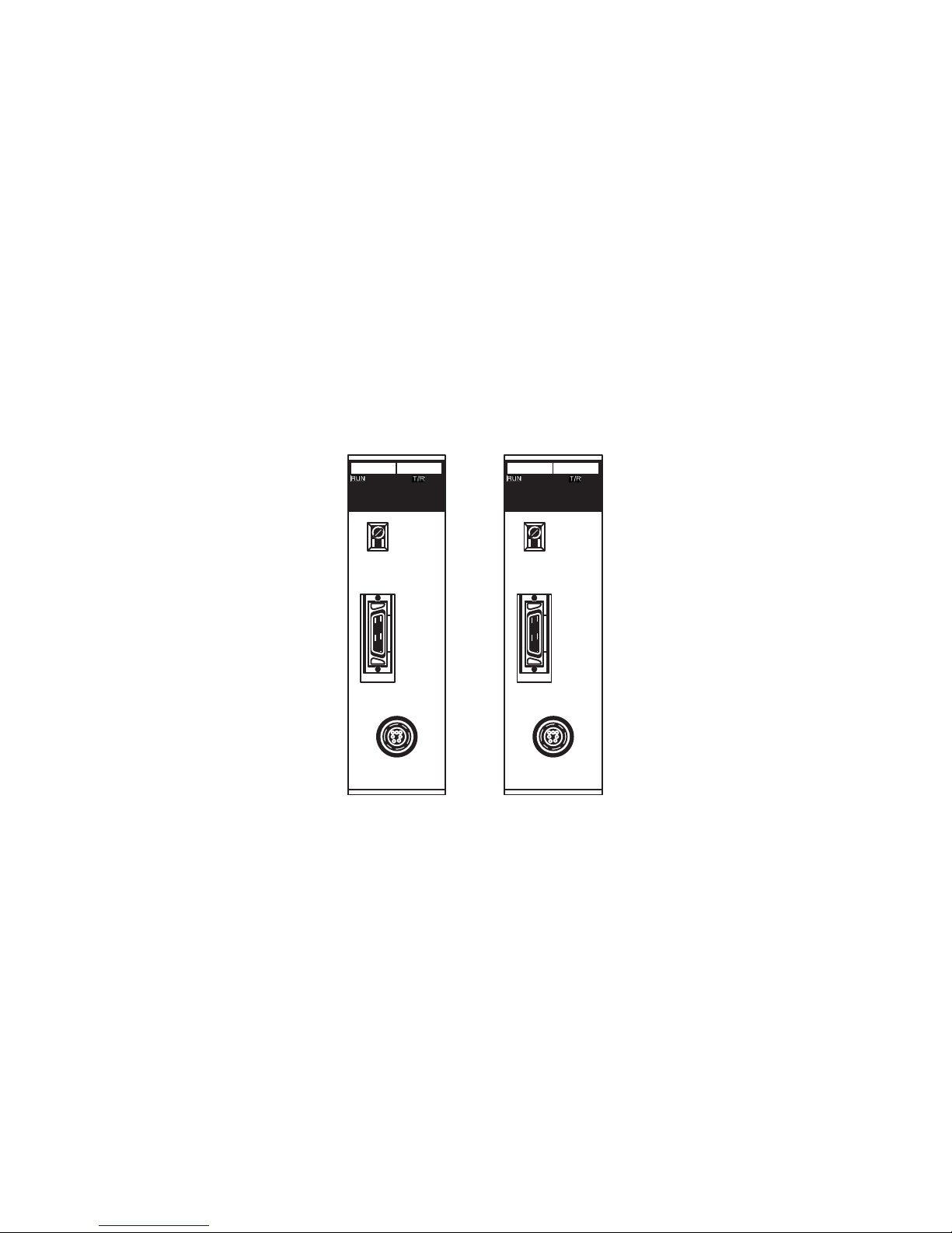
IDS01-V1
MONITOR
MACHINE
No
HEAD
IDS21
MONITOR
MACHINE
No
ANTENNA
Page 3

iv
Page 4

v
Notice:
OMRON products are manufactured for use according to proper procedures by a qualified operator
and only for the purposes described in this manual.
The following conventions are used to indicate and classify precautions in this manual. Always heed
the information provided with them. Failure to heed precautions can result in injury to people or damage to property.
!DANGER Indicates an imminently hazardous situation which, if not avoided, will result in death or
serious injury.
!WARNING Indicates a potentially hazardous situation which, if not avoided, could result in death or
serious injury.
!Caution Indicates a potentially hazardous situation which, if not avoided, may result in minor or
moderate injury, or property damage.
OMRON Product References
All OMRON products are capitalized in this manual. The word “Unit” is also capitalized when it refers to
an OMRON product, regardless of whether or not it appears in the proper name of the product.
The abbreviation “Ch,” which appears in some displays and on some OMRON products, often means
“word” and is abbreviated “Wd” in documentation in this sense.
The abbreviation “PC” means Programmable Controller and is not used as an abbreviation for anything else.
Visual Aids
The following headings appear in the left column of the manual to help you locate different types of
information.
Note Indicates information of particular interest for efficient and convenient opera-
tion of the product.
1,2,3... 1. Indicates lists of one sort or another, such as procedures, checklists, etc.
OMRON, 1990
All rights reserved. No part of this publication may be reproduced, stored in a retrieval system, or transmitted, in any form, o
r
by any means, mechanical, electronic, photocopying, recording, or otherwise, without the prior written permission o
f
OMRON.
No patent liability is assumed with respect to the use of the information contained herein. Moreover, because OMRON is constantly striving to improve its high-quality products, the information contained in this manual is subject to change without
notice. Every precaution has been taken in the preparation of this manual. Nevertheless, OMRON assumes no responsibility
for errors or omissions. Neither is any liability assumed for damages resulting from the use of the information contained in
this publication.
Page 5

vi
Page 6

vii
TABLE OF CONTENTS
PRECAUTIONS . . . . . . . . . . . . . . . . . . . . . . . . . . . . . . . . . . . xi
1 Intended Audience . . . . . . . . . . . . . . . . . . . . . . . . . . . . . . . . . . . . . . . . . . . . . . . . . . . . . . . . xii
2 General Precautions . . . . . . . . . . . . . . . . . . . . . . . . . . . . . . . . . . . . . . . . . . . . . . . . . . . . . . . xii
3 Safety Precautions. . . . . . . . . . . . . . . . . . . . . . . . . . . . . . . . . . . . . . . . . . . . . . . . . . . . . . . . . xii
4 Operating Environment Precautions . . . . . . . . . . . . . . . . . . . . . . . . . . . . . . . . . . . . . . . . . . . xiii
5 Application Precautions . . . . . . . . . . . . . . . . . . . . . . . . . . . . . . . . . . . . . . . . . . . . . . . . . . . .xiii
SECTION 1
System Description and Installation . . . . . . . . . . . . . . . . . . . 1
1-1 System Description . . . . . . . . . . . . . . . . . . . . . . . . . . . . . . . . . . . . . . . . . . . . . . . . . . . . . . . . 2
1-2 Features . . . . . . . . . . . . . . . . . . . . . . . . . . . . . . . . . . . . . . . . . . . . . . . . . . . . . . . . . . . . . . . . . 3
1-3 Components and Indicators. . . . . . . . . . . . . . . . . . . . . . . . . . . . . . . . . . . . . . . . . . . . . . . . . . 5
1-4 System Configuration . . . . . . . . . . . . . . . . . . . . . . . . . . . . . . . . . . . . . . . . . . . . . . . . . . . . . . 6
1-5 System Connections . . . . . . . . . . . . . . . . . . . . . . . . . . . . . . . . . . . . . . . . . . . . . . . . . . . . . . . 7
1-6 Maximum Distance Between ID Sensor Unit and R/W Head . . . . . . . . . . . . . . . . . . . . . . . 9
1-7 Maximum Distance Between ID Sensor Unit and R/W Antenna . . . . . . . . . . . . . . . . . . . . . 9
SECTION 2
Operation. . . . . . . . . . . . . . . . . . . . . . . . . . . . . . . . . . . . . . . . . 11
2-1 Switch Settings . . . . . . . . . . . . . . . . . . . . . . . . . . . . . . . . . . . . . . . . . . . . . . . . . . . . . . . . . . . 12
2-2 Word Settings . . . . . . . . . . . . . . . . . . . . . . . . . . . . . . . . . . . . . . . . . . . . . . . . . . . . . . . . . . . . 13
2-3 The User Program . . . . . . . . . . . . . . . . . . . . . . . . . . . . . . . . . . . . . . . . . . . . . . . . . . . . . . . . . 17
SECTION 3
Programming . . . . . . . . . . . . . . . . . . . . . . . . . . . . . . . . . . . . . 39
3-1 Program Examples . . . . . . . . . . . . . . . . . . . . . . . . . . . . . . . . . . . . . . . . . . . . . . . . . . . . . . . . 40
3-2 Monitoring . . . . . . . . . . . . . . . . . . . . . . . . . . . . . . . . . . . . . . . . . . . . . . . . . . . . . . . . . . . . . . 51
3-3 Timing Considerations . . . . . . . . . . . . . . . . . . . . . . . . . . . . . . . . . . . . . . . . . . . . . . . . . . . . . 70
SECTION 4
Troubleshooting . . . . . . . . . . . . . . . . . . . . . . . . . . . . . . . . . . . 73
4-1 Periodic Maintenance . . . . . . . . . . . . . . . . . . . . . . . . . . . . . . . . . . . . . . . . . . . . . . . . . . . . . . 74
4-2 What To Do If a Malfunction Occurs . . . . . . . . . . . . . . . . . . . . . . . . . . . . . . . . . . . . . . . . . . 74
4-3 Diagnostic Flowcharts. . . . . . . . . . . . . . . . . . . . . . . . . . . . . . . . . . . . . . . . . . . . . . . . . . . . . . 75
Appendices
A Specifications . . . . . . . . . . . . . . . . . . . . . . . . . . . . . . . . . . . . . . . . . . . . . . . . . . . . . . . . . . . . 77
B Standard Models . . . . . . . . . . . . . . . . . . . . . . . . . . . . . . . . . . . . . . . . . . . . . . . . . . . . . . . . . . 81
C ASCII Code List . . . . . . . . . . . . . . . . . . . . . . . . . . . . . . . . . . . . . . . . . . . . . . . . . . . . . . . . . . 83
D Using the C200H ID Sensor Unit with CS1-series PCs . . . . . . . . . . . . . . . . . . . . . . . . . . . . 85
Page 7

viii
TABLE OF CONTENTS
Glossary . . . . . . . . . . . . . . . . . . . . . . . . . . . . . . . . . . . . . . . . . . 89
Index . . . . . . . . . . . . . . . . . . . . . . . . . . . . . . . . . . . . . . . . . . . . 91
Revision History . . . . . . . . . . . . . . . . . . . . . . . . . . . . . . . . . . . 95
Page 8

ix
About this Manual:
This manual explains the operation of two non-contact information detection
systems: C200H–IDS01–V1 Electromagnetic Inductor ID Sensor Unit and
C200H–ID21 Microwave ID Sensor Unit. Both Units, having long-range sensing capabilities, can read information from or write information to a Data Carrier mounted to a moving work piece. Refer to separate manuals for
specifications and operation of the R/W Heads and Data Carriers. The table
below shows a list of manuals available for the V600/V620 FA ID System.
Before operating an ID Sensor Unit, thoroughly familiarize yourself with both
the Unit and this manual.
Section 1 describes the features, components, configuration, and installation
of the ID Sensor systems.
Section 2 describes operation of the ID Sensor Units, and covers switch settings, bit allocation, and communication commands, and introduces the user
program.
Section 3 describes programming and includes example programs that illustrate data transfer between the Unit and the CPU. Monitoring functions and
timing considerations are also covered in this section.
Section 4 contains information on maintenance and troubleshooting.
Four Appendices provide information on specifications and standard models,
and also includes an ASCII code list.
Name Catalog no.
Handheld ID Controller Operation Guide Z43
V600 FA ID System Serial Interface Operation Manual Z44
V600 FA ID System Parallel Interface Operation Manual Z45
FA ID System V620 ID System with Serial Interface System Manual Z68
FA ID System V620 ID System with Parallel Interface System Manual Z69
V600/620 FA ID System Operation Manual Z83
V600 FA ID System R/W Heads and SRAM Data Carriers
Operation Manual
Z95
V600 FA ID System R/W Heads and EEPROM Data Carriers
Operation Manual
Z96
V600 FA ID System R/W Heads and SRAM Data Carriers Supplement Z98
V600 FA ID System R/W Heads and EEPROM Data Carriers
Supplement
Z99
!WARNING Failure to read and understand the information provided in this manual may result in per-
sonal injury or death, damage to the product, or product failure. Please read each section
in its entirety and be sure you understand the information provided in the section and
related sections before attempting any of the procedures or operations given.
Page 9

Page 10

xi
PRECAUTIONS
This section provides general precautions for using the C500-IDS@@ ID Sensors and related devices.
The information contained in this section is important for the safe and reliable application of C500-IDS
@@ ID
Sensors. You must read this section and understand the information contained before attempting to set up or
operate a PC system.
1 Intended Audience . . . . . . . . . . . . . . . . . . . . . . . . . . . . . . . . . . . . . . . . . . . . . xii
2 General Precautions . . . . . . . . . . . . . . . . . . . . . . . . . . . . . . . . . . . . . . . . . . . . xii
3 Safety Precautions. . . . . . . . . . . . . . . . . . . . . . . . . . . . . . . . . . . . . . . . . . . . . . xii
4 Operating Environment Precautions . . . . . . . . . . . . . . . . . . . . . . . . . . . . . . . . xiii
5 Application Precautions . . . . . . . . . . . . . . . . . . . . . . . . . . . . . . . . . . . . . . . . . xiii
Page 11

xii
Intended Audience 1
1 Intended Audience
This manual is intended for the following personnel, who must also have
knowledge of electrical systems (an electrical engineer or the equivalent).
• Personnel in charge of installing control devices.
• Personnel in charge of designing control systems.
• Personnel in charge of managing control systems and facilities.
2 General Precautions
The user must operate the product according to the performance specifications described in the operation manuals.
Before using the product under conditions which are not described in the
manual or applying the product to nuclear control systems, railroad systems,
aviation systems, vehicles, combustion systems, medical equipment, amusement machines, safety equipment, and other systems, machines, and equipment that may have a serious influence on lives and property if used
improperly, consult your OMRON representative.
Make sure that the ratings and performance characteristics of the product are
sufficient for the systems, machines, and equipment, and be sure to provide
the systems, machines, and equipment with double safety mechanisms.
This manual provides information for operating the ID Sensor system. Be sure
to read this manual before attempting to use the ID Sensor systems and keep
this manual close at hand for reference during operation.
Since the V620 ID Sensor system uses microwaves of 2,450 MHz, permission
is required from the local electrical communications regulatory board before
installing the system.
!WARNING It is extremely important that ID Sensor systems be used for the specified pur-
pose and under the specified conditions, especially in applications that can
directly or indirectly affect human life. You must consult with your OMRON
representative before applying ID Sensor systems to the above-mentioned
applications.
3 Safety Precautions
!WARNING Do not attempt to disassemble, repair, or modify any Units. Any attempt to do
so may result in malfunction, fire, or electric shock.
!WARNING Do not attempt to take any Unit apart while the power is being supplied. Doing
so may result in electric shock.
!WARNING Do not touch any of the terminals or terminal blocks while the power is being
supplied. Doing so may result in electric shock.
!WARNING Do not throw the Data Carrier into fire or heat the Data Carrier to a tempera-
ture exceeding 100
°C. Doing so may cause ignition or burning of the built-in
lithium battery.
!WARNING Do not short the battery terminals or charge, disassemble, heat, or incinerate
the battery. Doing any of these may result in leakage, rupture, heat generation, or ignition of the battery.
Page 12

xiii
Operating Environment Precautions 4
!WARNING Provide safety measures in external circuits, i.e., not in the Programmable
Controller (CPU Unit including associated Units; referred to as "PC"), in order
to ensure safety in the system if an abnormality occurs due to malfunction of
the PC or another external factor affecting the PC operation. Not doing so
may result in serious accidents.
• Emergency stop circuits, interlock circuits, limit circuits, and similar safety
measures must be provided in external control circuits.
• The PC will turn OFF all outputs when its self-diagnosis function detects
any error or when a severe failure alarm (FALS) instruction is executed.
As a countermeasure for such errors, external safety measures must be
provided to ensure safety in the system.
• The PC outputs may remain ON or OFF due to deposition or burning of
the output relays or destruction of the output transistors. As a countermeasure for such problems, external safety measures must be provided
to ensure safety in the system.
4 Operating Environment Precautions
!Caution Do not operate the ID Sensor system in the following locations:
• Locations subject to direct sunlight.
• Locations subject to temperatures or humidity outside the range specified
in the specifications.
• Locations subject to condensation as the result of severe changes in temperature.
• Locations subject to corrosive or flammable gases.
• Locations subject to dust (especially iron dust) or salts.
• Locations subject to exposure to water, oil, or chemicals.
• Locations subject to shock or vibration.
!Caution Take appropriate and sufficient countermeasures when installing systems in
the following locations:
• Locations subject to static electricity or other forms of noise.
• Locations subject to strong electromagnetic fields.
• Locations subject to possible exposure to radioactivity.
• Locations close to power supplies.
!Caution The operating environment of the ID Sensor system can have a large effect on
the longevity and reliability of the system. Improper operating environments
can lead to malfunction, failure, and other unforeseeable problems with the ID
Sensor system. Be sure that the operating environment is within the specified
conditions at installation and remains within the specified conditions during
the life of the system.
5 Application Precautions
Observe the following precautions when using the ID Sensor system.
• Fail-safe measures must be taken by the customer to ensure safety in the
event of incorrect, missing, or abnormal signals caused by broken signal
lines, momentary power interruptions, or other causes.
• Interlock circuits, limit circuits, and similar safety measures in external circuits (i.e., not in the Programmable Controller) must be provided by the
customer.
Page 13

xiv
Application Precautions 5
!WARNING Always heed these precautions. Failure to abide by the following precautions
could lead to serious or possibly fatal injury.
• Always connect to a ground of 100
Ω or less when installing the ID Sen-
sor systems. Not connecting to a ground of 100
Ω or less may result in
electric shock.
• Always turn OFF the power supply to the PC before attempting any of the
following. Not turning OFF the power supply may result in malfunction or
electric shock.
• Mounting or dismounting Power Supply Units, I/O Units, CPU Units,
Memory Cassettes, or any other Units.
• Assembling the Units.
• Setting DIP switches or rotary switches.
• Connecting cables or wiring the system.
• Connecting or disconnecting the connectors.
!Caution Failure to abide by the following precautions could lead to faulty operation of
the PC or the system, or could damage the PC or PC Units. Always heed
these precautions.
• Always use the power supply voltages specified in the operation manuals.
An incorrect voltage may result in malfunction or burning.
• Take appropriate measures to ensure that the specified power with the
rated voltage and frequency is supplied. Be particularly careful in places
where the power supply is unstable. An incorrect power supply may result
in malfunction.
• Install external breakers and take other safety measures against short-circuiting in external wiring. Insufficient safety measures against short-circuiting may result in burning.
• Do not apply voltages to the Input Units in excess of the rated input voltage. Excess voltages may result in burning.
• Do not apply voltages or connect loads to the Output Units in excess of
the maximum switching capacity. Excess voltage or loads may result in
burning.
• Disconnect the functional ground terminal when performing withstand
voltage tests. Not disconnecting the functional ground terminal may result
in burning.
• Be sure that all the mounting screws, terminal screws, and cable connector screws are tightened to the torque specified in the relevant manuals.
Incorrect tightening torque may result in malfunction.
• Use crimp terminals for wiring. Do not connect bare stranded wires
directly to terminals. Connection of bare stranded wires may result in
burning.
• Double-check all wiring and switch settings before turning ON the power
supply. Incorrect wiring may result in burning.
• Be sure that the terminal blocks, Memory Units, expansion cables, and
other items with locking devices are properly locked into place. Improper
locking may result in malfunction.
• Check switch settings, the contents of the DM Area, and other preparations before starting operation. Starting operation without the proper settings or data may result in an unexpected operation.
• Check the user program for proper execution before actually running it on
the system. Not checking the program may result in an unexpected operation.
• Confirm that no adverse effect will occur in the system before attempting
any of the following. Not doing so may result in an unexpected operation.
Page 14

xv
Application Precautions 5
• Changing the operating mode of the PC.
• Force-setting/force-resetting any bit in memory.
• Changing the present value of any word or any set value in memory.
• Resume operation only after transferring to the new CPU Unit the contents of the DM Area, HR Area, and other data required for resuming
operation. Not doing so may result in an unexpected operation.
• Do not pull on the cables or bend the cables beyond their natural limit.
Doing either of these may break the cables.
• Do not place objects on top of the cables or other wiring lines. Doing so
may break the cables.
• When replacing parts, be sure to confirm that the rating of a new part is
correct. Not doing so may result in malfunction or burning.
• Before touching a Unit, be sure to first touch a grounded metallic object in
order to discharge any static built-up. Not doing so may result in malfunction or damage.
• Install the Units properly as specified in the operation manuals. Improper
installation of the Units may result in malfunction.
Page 15

xvi
Application Precautions 5
Page 16

1
SECTION 1
System Description and Installation
This section describes the features, components, configuration, and installation of the ID Sensor systems.
1-1 System Description . . . . . . . . . . . . . . . . . . . . . . . . . . . . . . . . . . . . . . . . . . . . . 2
1-2 Features . . . . . . . . . . . . . . . . . . . . . . . . . . . . . . . . . . . . . . . . . . . . . . . . . . . . . . 3
1-3 Components and Indicators. . . . . . . . . . . . . . . . . . . . . . . . . . . . . . . . . . . . . . . 5
1-4 System Configuration . . . . . . . . . . . . . . . . . . . . . . . . . . . . . . . . . . . . . . . . . . . 6
1-5 System Connections . . . . . . . . . . . . . . . . . . . . . . . . . . . . . . . . . . . . . . . . . . . . 7
1-6 Maximum Distance Between ID Sensor Unit and R/W Head . . . . . . . . . . . . 9
1-7 Maximum Distance Between ID Sensor Unit and R/W Antenna . . . . . . . . . . 9
Page 17
2
System Description Section 1-1
Section Overview This manual covers the operation of two ID Sensor models, the C200H-
IDS01-V1 Electromagnetic Induction ID Sensor Unit and the C200H-IDS21
Microwave ID Sensor Unit. The main difference between the Units is the distance at which the ID Sensor can read data from or write data to the Data Carrier. The Microwave ID Sensor Unit allows the Data Carrier to be placed
farther from the Unit.
This section describes the components, installation, and configuration of both
models.
1-1 System Description
The ID Sensor system is a versatile noncontact identification system comprising an ID Sensor Unit, a single Read/Write (R/W) Head or Antenna, and a
Data Carrier.
The ID Sensor mounts to a C200H Programmable Controller (PC); the Data
Carrier mounts to a moving workpiece or workpiece carrier. The R/W Head or
Antenna, connected to the ID Sensor Unit by a cable, must be positioned
within communication range of the travel path of the Data Carrier. Responding
to commands from the user program in the CPU of the PC, the ID Sensor
reads data from or writes data to the Data Carrier through the R/W Head or
Antenna. The operation of the ID Sensor can be monitored and tested with
the Handheld Programming Console; messages appear on the display of the
Console.
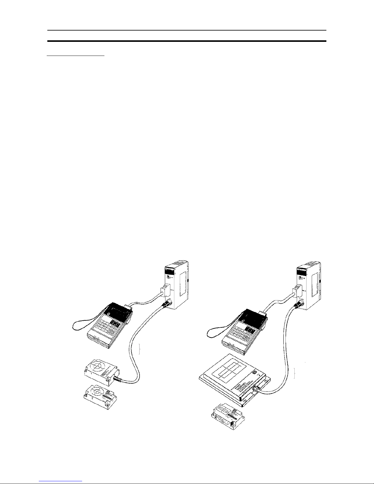
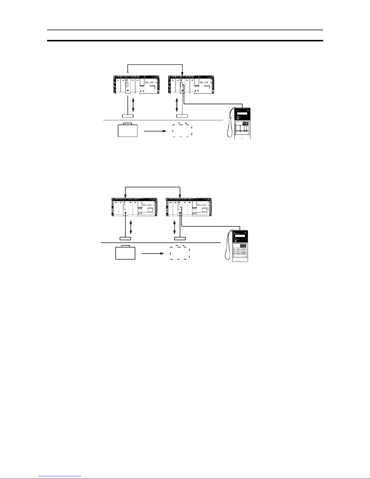
The following diagram illustrates two ID Sensor systems, one using a C200HIDS01-V1 ID Sensor and one using a C200H-IDS21 ID Sensor.
C200H ID Sensor Systems
Connecting Cable
R/W Antenna
V620 series
Data Carrier
V620 series
Connecting Cable
Hand-held Programming Console*
C200H-PRO27-E
30.5 m max. when using the V600-H07
50.5 m max. when using the V600-H11/H51/H52
10 m max.
Hand-held Programming Console*
C200H-PRO27-E
Read/Write
Head V600
series
Data Carrier
V600 series
Microwave ID Sensor
Unit (C200H-IDS21)
Electromagnetic Induction ID
Sensor Unit (C200H-IDS01-V1)
Connecting Cable
Page 18

3
Features Section 1-2
1-2 Features
The ID Sensor systems have the following features:
Seven Dedicated
Commands
Data is transferred between the ID Sensor Unit and the Data Carrier with the
following six dedicated commands:
Read
Write
Auto Read
Auto Write
Clear-all
Auto Read/Write Abort
Data management (C200H-IDS01-V1 only)
Up to 1024 bytes of data can be read from or written to the Data Carrier at
one time. Clear-all clears all data in the Data Carrier’s memory (2K bytes).
These commands are compatible with the V600 and V620 ID Controllers.
Monitoring with the
Handheld Programming
Console
The Handheld Programming Console can be used for monitoring data transfer
as well as errors that have occurred during operation. A keyboard sheet for
the Handheld Programming Console is included with the ID Sensor Unit.
Storage of Error
Information
Error information is stored in the internal memory of the ID Sensor Unit. A
built-in capacitor stores the information for 15 days (at 25
°C).
Compatibility The following table lists the compatibility between the I/D Sensor Unit and the
R/W Head, R/W Antenna, or Data Carrier.
Note Refer to the list of applicable manuals in the About this Manual section.
Differences between
C200H-IDS01 and
C200H-IDS01-V1
The C200H-IDS01-V1, which is an updated version of the C200H-IDS01, has
the following three new features in addition to all the capabilities that the
C200H-IDS01 possesses. The C200H-IDS01 is compatible with the C200HIDS01-V1.
1,2,3... 1. Connecting to Data Carrier Incorporating EEPROM
The C200H-IDS01-V1 reads data from and writes data to the V600-D@@P@@
containing an EEPROM. To read data, the user can select the communications distance priority mode or communications speed priority mode with the
local communications mode pin (pin 3 of the DIP switch). Neither of these
modes are, however, available when the ID Sensor Unit is connected to the
SRAM Data Carrier.
ID Sensor Electromagnetic induction Microwave
V600-H@@ R/W
Head
V600-D@@R@@
Data Carrier (with
built-in battery)
V600-D@@P@@
Data Carrier (with
no built-in
battery)
V620-H@@ R/W
Antenna
V620-D@@R@@
Data Carrier (with
built-in battery)
C200H-IDS01-V1 Yes Yes Yes No No
C200H-IDS01 Yes Yes No No No
C200H-IDS21 No No No V620-H01/-H02 V620-D8KR01
3
4
1
2
Local communications mode pin
Page 19

4
Features Section 1-2
2. New Commands
The C200H-IDS01-V1 incorporates data management commands, with which
it is possible to check the reliability of the Data Carrier’s data. The details of
the commands are as follows:
3. Hexadecimal Page Number Display
The page number is displayed in hexadecimal, in which case the rightmost
two digits of the address are displayed as the page number.
In the following example, the user has access to address 0A00 or 1000.
Function Command Meaning
Checking of data MD-K By adding a check code to the Data Carrier’s data, it is possible to detect a data
error due to the battery of the Data Carrier that incorporates SRAM, or
excessive overwriting operations of the Data Carrier that incorporates
EEPROM. Use the MD-K command to calculate and write the check code to the
Data Carrier. Use the MD-C command to collate the check code. The MD-K
command and MD-C command must be always used together.
MD-C
Checking of the number
of overwriting operations
MD-L Check the life of the Data Carrier’s EEPROM by counting the number of
overwriting operations. The Data Carrier’s EEPROM allows a total of 100,000
overwriting operations.
MD-S Use this command to specify the number of overwriting operations in the life of
the EEPROM in advance. Every time a write operation is performed, 1 is
subtracted and the Data Carrier will detect when the life has expired. This command is only available with models of lot number @@55 (May 1995) or later.
C200H-IDS01-V1 C200H-IDS01
C200H-IDS21
HEAD 1 PAGE 0A
STadrs00 data 00
ANT. PAGE 10
STadrs00 data 00
Page 20
5
Components and Indicators Section 1-3
1-3 Components and Indicators
Although similar in appearance, note that the C200H-IDS01-V1 ID Sensor
reads or writes data through a Read/Write Head and the C200H-IDS21 reads
or writes data through a Read/Write Antenna.
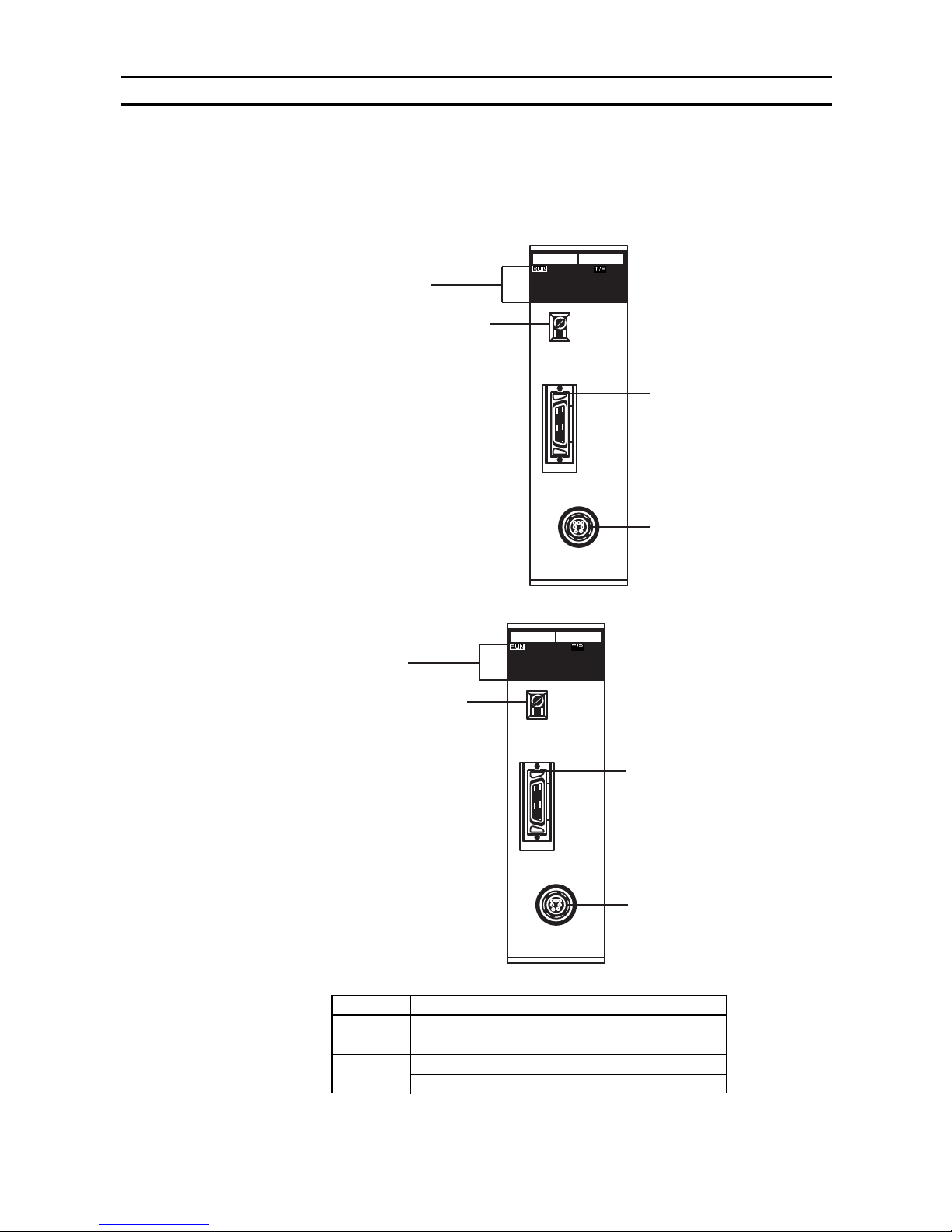
C200H-IDS01-V1 Front Panel
C200H-IDS21 Front Panel
Indicators The table below explains the status of the indicators on both models.
Indicators
Unit number switch
( "Machine No.")
Handheld Programming
Console connector
Read/Write Head
connector
IDS01-V1
MONITOR
MACHINE
No
HEAD
Indicators
Unit number switch
( "Machine No.")
Handheld Programming
Console connector
Read/Write Antenna
connector
IDS21
MONITOR
MACHINE
No
ANTENNA
Indicator Function
RUN Lit (green) while the ID Sensor is operating.
Unlit if an error occurs in the ID Sensor Unit.
T/R Lit (green) during data communication.
Unlit when data is not transmitted.
Page 21
6
System Configuration Section 1-4
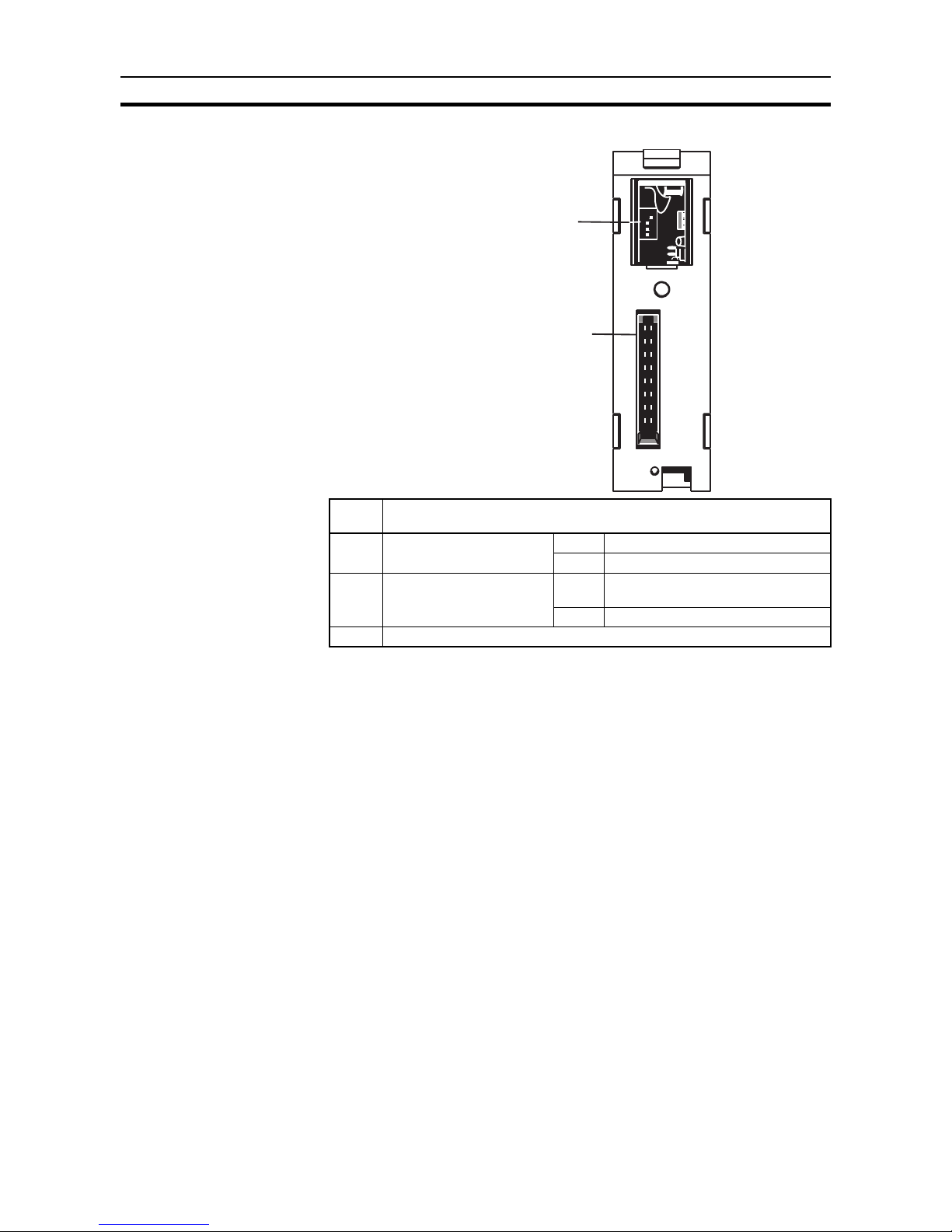
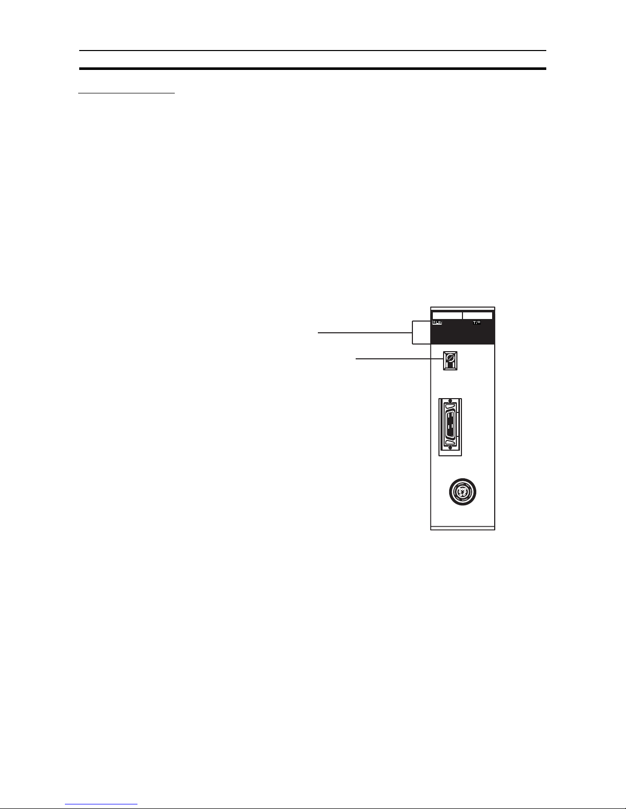
Back Panel C200H-IDS01-V1/IDS21
Note The user can select the communications distance priority mode or
communications speed priority mode with pin 2 of the DIP switch
when the C200H-IDS01-V1 accesses the EEPROM Data Carrier.
Neither of these modes are, however, available when the ID Sensor
Unit accesses the SRAM Data Carrier or when the C200H-IDS21 accesses any Data Carrier, in which case turn pin 2 OFF. Refer to the
V600 FA ID System R/W Heads and EEPROM Data Carriers Operation Manual for the communications distance and speed of the EE-
PROM Data Carrier.
1-4 System Configuration
The diagrams below illustrate the system configurations of the C200H-IDS01V1 Electromagnetic Induction ID Sensor Unit and the C200H-IDS21 Microwave ID Sensor Unit.
The ID Sensor Unit transfers data through the Read/Write Head (or Antenna)
to a Data Carrier, which is mounted on a moving workpiece. The ID Sensor
Unit transfers the desired data according to instructions from the user program in the CPU (refer to 2-3 The User Program). Only one Read/Write Head
(or Antenna) can be connected to the ID Sensor Unit.
Data and error information can be monitored through a Handheld Programming Console connected to the ID Sensor Unit. The data is displayed on the
screen of the Programming Console.
Pin
No.
Function
1 Screen messages OFF Japanese
ON English
2 Local communications
mode (see note)
OFF Communications distance priority
mode
ON Communications speed priority mode
3, 4 Always OFF
DIP switch
Backplane connector
Page 22
7
System Connections Section 1-5
C200H-IDS01-V1 Electromagnetic Induction ID Sensor
C200H-IDS21 Microwave ID Sensor Unit
1-5 System Connections
Mounting the ID Sensor
Unit
As a Special I/O Unit, an ID Sensor Unit can be mounted to any slot on the
C200H PC Backplane except the two rightmost slots; these two slots are
reserved for peripheral devices.
Up to ten Special I/O Units can be mounted to a PC system. (The PC Link
Unit, used to link two PCs, is a Special I/O Unit.) The number of ID Sensor
Units which can be connected may be limited by the size of the Backplane,
the Power Supply, and the current consumption of each Unit. For details, refer
to the C200H Programmable Controller Installation Guide.
Mounting to a Remote I/O
Slave Rack
The maximum number of Special I/O Units that can be mounted to a Remote
Slave Rack differs depending on the group (A, B, C, or D, as shown in the following table) to which they belong.
C200H
ID Sensor Unit
C200H
Connecting Cable
Read/
Write Head
Read/Write
data
Data Carrier
Work
piece
Movement
Work
Hand-held Programming Console
(Attach the keyboard accessory
sheet, supplied with the ID Sensor
Unit, to the Programming Console.)
Read/Write
Head
C200H
ID Sensor Unit
C200H
Connecting Cable
R/W
Antenna
Read/Write
data
Data Carrier
Work
piece
Movement
Work
R/W
Antenna
Hand-held Programming Console
(Attach the keyboard accessory
sheet, supplied with the ID Sensor
Unit, to the Programming Console.)
Page 23

8
System Connections Section 1-5
The information in this table applies only when no other Special I/O Units are
mounted to other Racks (PC or Expansion I/O Racks) and the Units in this
table are mounted only to a Remote I/O Slave Rack.
When combining Units from groups A, B, C, and D, use the following formulae:
3A + B + 2C + 6D
≤ 12
A + B + C + D
≤ 8
A maximum of ten Units can be mounted to one Remote I/O Slave Rack.
However, when mounting ten Units, the NC211 Position Control Unit is
counted as two Units and, if a PC Link Unit is used, it is counted as one Unit.
Connecting the ID System Refer to page 2 for an illustration of system connections.
Before connecting and wiring the ID Sensor Unit, turn OFF the power to the
PC.
Connect the R/W Head or Antenna to the ID Sensor Unit connector marked
“HEAD” or “Antenna”. (To disconnect the cable, pull while grasping the outer
ring of the cable; do not pull at an angle.)
Connecting the Handheld
Programming Console
Refer to 3-2 Monitoring for information on connecting the Handheld Program-
ming Console.
The Next Step Once you have completed installation of the ID Sensor system, turn to
SEC-
TION 2 Operation
for details on setup and operation.
ABCD
High-speed
Counter, Position
Control Unit
(NC111/NC112),
ASCII Unit, Analog
I/O Unit, ID Sensor
Unit, Fuzzy Logic
Unit
High-density I/O
Units, Temperature
Control Units, Cam
Positioner Unit
Temperature
Sensor Unit, Voice
Unit
Position Control
Unit (NC211)
4 Units max. --- --- ---
--- 8 Units max. --- ---
--- --- 6 Units max. ---
--- --- --- 2 Units max.
Page 24

9
Maximum Distance Between ID Sensor Unit and R/W Head Section 1-6
1-6 Maximum Distance Between ID Sensor Unit and R/W Head
Note With the C500-IDS02 (V1), the maximum cable length between the IDS02
(V1) and IDA02 is 200 m max. The length shown above is a distance between
the IDA02 and the R/W Head.
1-7 Maximum Distance Between ID Sensor Unit and R/W
Antenna
Note With the C500-IDS22, the maximum cable length between the IDS22 and
IDA22 is 200 m max. This length shown above is a distance between the
IDA22 and the R/W Head.
R/W Head C500 C200
IDS01-V1 IDS01-V2 IDS02 IDS02-V1 IDS01 IDS01-V1
V600-H52
(V600-D23P52)
(V600-D23P54)
--- 50.5 m --- 10 m --- 50.5 m
V600-H51
(V600-D23P61)
--- 50.5 m --- 10 m --- 50.5 m
V600-H11
(V600-D23P72)
(V600-D23P61)
(V600-D2KR16)
--- 50.5 m --- 10 m --- 50.5 m
V600-H07
(V600-D23P71)
(V600-D23P72)
30.5 m for lots
manufactured
in or after 1991
and 10 m for
lots manufactured before
1991.
30.5 m 10 m 10 m 30.5 m for lots
manufactured
in or after 1992
and 10 m for
lots manufactured before
1992.
30.5 m
V600-H06 10 m 30.5 m 10 m 10 m 10 m 30.5 m
R/W Antenna C500 C200H-IDS21
IDS21 IDS22
V620-H01
(microwave)
10 m 10 m 10 m
Page 25

Page 26

11
SECTION 2
Operation
This section describes operation of the ID Sensor Units, and covers switch settings, bit allocation, and communication
commands, and introduces the user program.
2-1 Switch Settings . . . . . . . . . . . . . . . . . . . . . . . . . . . . . . . . . . . . . . . . . . . . . . . . 12
2-2 Word Settings . . . . . . . . . . . . . . . . . . . . . . . . . . . . . . . . . . . . . . . . . . . . . . . . . 13
2-3 The User Program . . . . . . . . . . . . . . . . . . . . . . . . . . . . . . . . . . . . . . . . . . . . . . 17
2-3-1 Communication Commands . . . . . . . . . . . . . . . . . . . . . . . . . . . . . . . 19
2-3-2 Data Carrier Memory . . . . . . . . . . . . . . . . . . . . . . . . . . . . . . . . . . . . 29
2-3-3 Write Protection Function. . . . . . . . . . . . . . . . . . . . . . . . . . . . . . . . . 30
2-3-4 Write Protection Examples. . . . . . . . . . . . . . . . . . . . . . . . . . . . . . . . 32
2-3-5 The Data Carrier’s Production Date . . . . . . . . . . . . . . . . . . . . . . . . . 36
2-3-6 Detection of Data Carrier’s Life. . . . . . . . . . . . . . . . . . . . . . . . . . . . 37
Page 27
12
Switch Settings Section 2-1
Section Overview This section contains information on switch settings, bit allocation, and setup
of both ID Sensor systems, as well as explanations of the user program, communication commands, and the write-protect function.
2-1 Switch Settings
Unit Number Switch Before beginning operation, use the unit number switch on the front panel to
set the unit number (0 through 9) of the ID Sensor Unit. Each Special I/O Unit
must be assigned its own number; if the same number is assigned to more
than one Unit, an I/O Unit Over error will occur, preventing system operation.
To set the unit number:
1,2,3... 1. Determine the appropriate unit number (refer to 1-5 System Connections
for information on Special I/O Units).
2. Turn OFF the power to the PC.
3. Using a small standard screwdriver, turn the dial to the desired number.
The dial clicks into position at each number setting; do not leave the dial
between settings.
Back Panel DIP Switch (Refer to the diagram of the back panel on page 5.) Pin 1 is used to select the
language of the Programming Console display; leave this pin at the ON (left)
position for English message display. Pins 2 through 4 are for reserved for
expansion; leave these pins at the OFF (right) position.
Indicators
Unit number switch
(MACHINE No.)
IDS01-V1
MONITOR
MACHINE
No
ANTENNA
Page 28
13
Word Settings Section 2-2
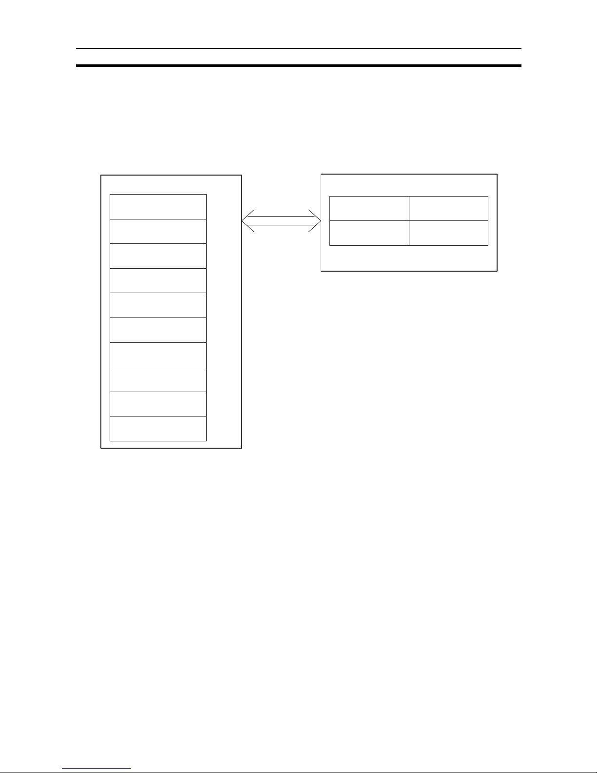
2-2 Word Settings
Words 100 through 199 in the IR area of the PC are reserved for Special I/O
Units. Each Special I/O Unit is assigned ten words, of which five are needed.
These five words, used by the ID Sensor or other Special I/O Units for data
communication, are referred to as I/O refresh data (stored in the I/O refresh
data area). The five words that are not used can be used as work bits.
Note Each Unit must be assigned a different unit number. If two or more Special I/O
Units are assigned the same unit number, the system is unable to determine
which Unit is to be accessed and an I/O Unit Over error occurs, halting the
system.
PC (C200H)
IR area
words 100 through 104
words 110 through 114
words 120 through 124
words 130 through 134
words 140 through 144
words 150 through 154
words 160 through 164
words 170 through 174
words 180 through 184
words 190 through 194
Unit 0
Unit 1
Unit 2
Unit 3
Unit 4
Unit 5
Unit 6
Unit 7
Unit 8
Unit 9
I/O refresh data
is transferred to
each Unit.
ID Sensor Unit
I/O refresh
words n through
n+3
word n+4
OUT refresh
IN refresh
5 words are used.
(n = 100 + 10 x unit number)
Page 29

14
Word Settings Section 2-2
IR Bit Allocation
Note 1. Only 512 words of data can be read or written, 4 words are used for com-
mand data.
2. At the leading edge of a command signal, the data of word n+1 through
word n+3 is valid.
3. The unused bits are provided for expansion. Do not use as work bits.
Word Bit number Bit name Function
n 00 Command
execution flag
At the leading edge of the signal, the ID Sensor Unit reads
and executes the command.
01 Error reset flag While the ID Sensor Unit is waiting for a command, the error
reset flag is turned ON and the error flags in word n+4, bits 08
through 15 are turned OFF.
02 through 15 – Not used (see note 3).
n+1
(see note 2)
00 through 11 No. of command
data words
Indicates, in Binary Coded Decimal (BCD), the number of
words in the command to be executed. The maximum number
of words is 516 (see note 1).
12 through 15 – Not used (see note 3).
n+2
(see note 2)
00 through 11 Command data
storage area
beginning word
number
Indicates, in BCD, the beginning word of the command to be
executed (stored in the CPU).
When the DM area exceeds DM 1000, turn ON bit 12.
12 through 15 Command data
storage area
n+3
(see note 2)
00 through 11 Read data receiving
area beginning word
number
The CPU reads the data from the Data Carrier using Read or
Auto Read. Specifies the beginning word of the area (in the
CPU) where the data is stored. The data is ignored when
Write, Auto Write, Clear-all, or Auto Read/Write Abort is
executed.
12 through 15 Read data receiving
area
Specifies the area in the CPU in which the data read from the
Data Carrier (using Read or Auto Read) is stored. Refer to
word n+2, bits 12 through 15, to determine data areas. The
data is ignored when Write, Auto Write, Clear-all or Auto Read
or Auto Read/Write Abort is executed.
Indicates the area where the command to be executed is
stored.
Bit number
15 14 13 12
0
1
00
0
0
0
0
0
0
0
0
0
0
0
0
0
***
1
1
1
11
1
Area name
DM area
IR area
HR area
AR area
LR area
TIM/CNT
***When the DM area exceeds DM 1000, turn ON bit 12.
Page 30

15
Word Settings Section 2-2
Word Bit number Bit name Function
n+4 00 ID busy This flag turns ON while the ID Sensor Unit is executing a
command.
01 Waiting for Data
Carrier
During the execution of Auto Read or Auto Write, this flag is
ON while it is waiting for the Data Carrier to approach the
Read/Write Head (or Antenna).
02 Auto Read/Write
Abort end
This flag turns ON when the ID Sensor Unit has received
(from the CPU) and completed Auto Read/Write Abort.
03 Programming
Console MONITOR
mode
This flag turns ON when the Programming Console
(connected to the ID Sensor Unit) is in MONITOR mode.
04 through 06 – Not used
07 Data Carrier warning This flag turns ON when the Data Carrier’s battery is almost
dead. This flag also turns ON when the MD-C command
detects a data check error or when the MD-L/MD-S command
detects that the number of overwriting operations reaches the
specified number.
08 Read format error During the execution of Read or Auto Read, this flag is ON
when the data in the Data Carrier exceeds the capacity of the
receiving area. (Refer to Read/Write Bit Areas page 16.)
09 Command error This flag is ON when the ID Sensor Unit cannot process the
command sent from the CPU. The command may be
undefined or may not have a terminator.
10 No Data Carrier
error
This flag turns ON when the Data Carrier is undetected by the
ID Sensor after the ID Sensor has received Read, Write, or
Clear-all from the CPU.
11 Write protect error This flag turns ON when an attempt is made to write data to a
write-protected area of the ID Sensor Unit’s memory.
12 Data Carrier
communication
error
This flag turns ON if an error has occurred during data
communication between the ID Sensor Unit and Data Carrier.
13 Data Carrier
address over
This flag turns ON when the ID Sensor Unit attempts to
access an address of the Data Carrier which is beyond the
Data Carrier’s memory capacity.
14 Data verification
error
As the ID Sensor Unit reads data from or writes data to the
Data Carrier, the ID Sensor Unit compares the current data
with previously read or written data. If the data is not identical,
an error occurs and this flag turns ON.
15 Read/Write Head (or
Antenna)
disconnect error
This flag turns ON when the Read/Write Head is improperly
connected to the ID Sensor Unit.
Page 31

16
Word Settings Section 2-2
Read/Write Bit Areas The following table shows the memory areas (bits) that the ID Sensor Unit
uses when reading data from or writing data to the Data Carrier.
If, during execution of Read or Auto Read, the data read from the Data Carrier
exceeds the capacity of the receiving area, a Read Format error occurs and
word n+4, bit 08 turns ON.
Example:
Data Carrier Read data: 40 bytes = 20 words
Beginning word number (receiving data): DM 1990
As the above table shows, the words specified in the DM area are DM 0000
through DM 1999. If the beginning word number is DM 1990, only 10 words
(DM 1990 through 1999) are available for receiving data. In this example, the
quantity of data to be read is too large for the available space in the DM area.
A Read Format error will occur and the data will not be written to the DM area.
To correct the error, change the beginning word number (receiving data) to a
word number less than DM 1980, or reduce the quantity of data in the Data
Carrier to fewer than 10 words.
Error Storage Area The error information storage area of the ID Sensor Unit is undefined at ship-
ment. Before using the ID Sensor Unit, clear the newest error information and
statistical error information. (Refer to 3-2-9 Error Log Display (ERR) for
details).
Error Messages and Reset
Flags
The ID Sensor Unit’s error messages and reset flags are located in the AR
area as “Special I/O Unit Error Message” and “Special I/O Unit Reset Flag”.
Refer to the C200H Programmable Controller Operation Manual for details.
When the error message flag for a particular unit number is ON, the RUN LED
of the corresponding Special I/O Unit turns OFF.
Area
DM area
IR area
HR area
AR area
LR area
TC area
Bits
DM 0000 through 1999
000 through 246
HR 00 through 99
AR 07 through 22
LR 00 through 63
TC 000 through 511
Special I/O Unit Error Message
Special I/O Unit Reset Flag
AR 0000 through AR 0009
AR 0100 through AR 0109
Page 32

17
The User Program Section 2-3
2-3 The User Program
The ID Sensor Unit will not function unless the PC is programmed to control
the operation of the Unit. The Unit communicates with the Data Carrier
through the Read/Write Head by means of the commands provided by the
user program of the PC.
Program examples with detailed explanations are provided in Section 3-1
Program Examples.
The following figure shows the basic operation outline of the program.
Operation Outline
Effect of CPU Status on ID
Sensor Unit
The ID Sensor Unit is controlled by the program contained in the CPU; if an
error occurs in the CPU, an error will also occur in the ID Sensor Unit.
The ID Sensor Unit will continue to execute commands when the PC is in
PROGRAM mode.
Communication with the
CPU
The ID Sensor Unit reads data from and writes data to the Data Carrier in
accordance with the commands sent from the CPU.
PC
Word data
Dedicated command
Read data
User program
MOV, OUT etc.
(Command execution flag)
MOV, LD instruction etc.
(Error information)
Common
memory
I/O word
words n
through
n+4
ID Sensor Unit
Internal program
Analyzes the
command
and transfers
the data
between PC
and Data
Carrier
Executes
handshaking
and processes error
information
R/W
Head
Data
Carrier
Page 33

18
The User Program Section 2-3
Writing Data to the Data
Carrier from the CPU
The CPU, via the Write, Auto Write, and Clear-all commands, directs the ID
Sensor Unit to write data to the Data Carrier. The following diagram shows
how the program writes data to the Data Carrier.
1. The CPU sends the command data (the number of words in the command to be sent, the beginning word number of the command, and
the command execution start) to the ID Sensor Unit by using MOV or
OUT.
2. The ID Sensor Unit analyzes the command received from the CPU.
3a. If the command is legal, the ID Sensor Unit writes the required data to
the Data Carrier.
3b. If the command is illegal, the ID Sensor Unit sets the Command Error
flag (word n+4 bit 09) to ON and returns the data to the CPU. At this
time, the ID Busy flag (word n+4 bit 00) is turned OFF.
4. When the ID Sensor Unit has completed communication with the
Data Carrier, the Unit turns OFF the ID Busy flag as the command is
completed, and returns the data to the CPU.
If communication with the Data Carrier fails, or if an error occurs during communication, the ID Sensor Unit stops data communication with the Data Carrier, turns ON the Data Carrier communication error flags, returns the data to
the PC, and turns OFF the ID Busy flag.
Steps 1 to 4 compose one write operation.
Reading Data from the
Data Carrier to the CPU
The CPU, via the Read and Auto Read commands, directs the ID Sensor Unit
to read data from the Data Carrier to the CPU. The following diagram shows
how the program reads data from the Data Carrier.
1. The CPU sends command data (the number of words in the command, the beginning word number of the command, and the beginning word number of the data to be received) to the ID Sensor Unit by
using MOV or OUT.
2. The ID Sensor Unit analyzes the command received from the CPU.
3a. If the command is legal, the ID Sensor Unit reads the required data to
the Data Carrier.
CPU
ID Sensor
Unit
1
3b
4
2
3a
R/W
Head
Data
Carrier
CPU
ID Sensor
Unit
1
3b
4
2
3a
R/W
Head
Data
Carrier
Page 34

19
The User Program Section 2-3
3b. If the command is illegal, or the Read format is illegal, the ID Sensor
Unit turns ON both the Command Error flag (word n+4 bit 09) and the
Read Format Error flag (word n+4 bit 08), and returns the data to the
PC. At this time, the ID Busy flag (word n+4 bit 00) is turned OFF.
4. When the ID Sensor Unit has completed communication with the
Data Carrier (step 4), the ID Sensor Unit forwards the read data to the
CPU; the Unit turns OFF the ID Busy flag as the command is completed.
If communication with the Data Carrier fails, or if an error occurs during communication, the ID Sensor Unit stops data communication with the Data Carrier, turns ON the Data Carrier communication error flags, returns the data to
the CPU, and turns OFF the ID Busy flag.
Steps 1 to 4 compose one read operation.
2-3-1 Communication Commands
The ID Sensor Unit is provided with seven dedicated commands for communicating with the Data Carrier through the Read/Write Head. The following table
outlines these commands.
Note The Clearall command clears the Data Carrier’s internal memory, regardless
of write protection.
When transferring data between the Data Carrier and the ID Sensor Unit, up
to 1024 bytes (512 words) of data per scan can be written to or read from the
Data Carrier. However, when transferring data between the PC and the ID
Sensor Unit, only 20 words can be transferred per scan. Data is transferred
between the PC and the ID Sensor Unit at a rate of 0.2 ms per word.
If data is to be read and written simultaneously, the read data can be up to 20
words (40 bytes) in length and the write data can be up to 16 words (32 bytes)
in length. (Because the write data is transferred with the command data,
which requires 4 of the 20 words, only 16 words are available to carry the
write data.) If the data exceeds 20 words, more than one scan is required to
transfer the data between the CPU and the ID Sensor Unit, making simultaneous processing impossible.
For details refer to 3-3 Timing Considerations.
Command name Mnemonic ASCII
code
Function
Write WT 57 54 Writes data to the internal memory of the Data Carrier; up to1024 bytes
(512 words) of data can be written at a time.
Read RD 52 44 Reads data from the internal memory of the Data Carrier; up to 1024
bytes (512 words) of data can be read at a time.
Auto Write AW 41 57 Waits until the Data Carrier approaches the Read/Write Head and then
writes data to the internal memory of the Data Carrier as it comes within
detection range of the Read/Write Head. Up to 1024 bytes (512 words) of
data can be written at a time.
Auto Read AR 41 52 Waits until the Data Carrier approaches the Read/Write Head and then
reads data from the internal memory of the Data Carrier as it comes
within detection range of the Read/Write Head. Up to 1024 bytes (512
words) of data can be read at a time.
Clear-all
(see note)
CA 43 41 Clears the contents of the Data Carrier’s internal memory.
Auto Read/Write Abort AA 41 41 Aborts Auto Read and Auto Write. When this command is executed, the
ID Sensor Unit is initialized and waits for the next command.
Data management
(C200H-IDS01-V1
only)
MD 4D 44 Checks the Data Carrier’s internal memory. The reliability of data is
checked using the MD-K and MD-C commands and the number of
overwriting operations is checked using the MD-L and MD-S commands.
Page 35

20
The User Program Section 2-3
Write Command This command writes data to the internal memory of the Data Carrier. Up to
1024 bytes (512 words) of data can be written per scan. Specify the first
address in hexadecimal.
Specifies the type of
data to be written,
which can be ASCII
characters or hexadecimal numbers. Code A
(41) specifies ASCII
characters, while H (48)
specifies hexadecimal
numbers.
15
W
57
A/H
41/48
2
*
A
00
T
54
1
31
0D
This is OP (operation) code indicating
that the command is Write.
This is OP code represented in
ASCII code.
This code selects a Read/Write Head
and is always fixed to 1.
ASCII code
Specifies the first address of the Data
Carrier memory to which data is to be
written. Addresses $0000 through
$FFFF can be specified in hexadecimal.
Write data
Terminator
ASCII code
• 1024 bytes max. = 512 words
Page 36

21
The User Program Section 2-3
Read Command The Read command reads data from the internal memory of the Data Carrier.
Up to 1024 bytes (512 words) of data can be read at a time. Specify the first
address and the number of bytes in hexadecimal.
15
R
52
A/H
41/48
2
*
A
00
D
44
1
31
0D
This is OP (operation) code indicating
that the command is Read.
This is OP code represented in ASCII
code.
This code selects a Read/Write Head
and is always fixed to 1.
ASCII code
Specifies the first address of the Data
Carrier memory to which data is to be
read. Addresses $0000 through $FFFF
can be specified in hexadecimal.
Terminator
ASCII code
This field specifies
whether the data to
be read from the
Data Carrier is ASCII
characters or hexadecimal code. When
ASCII characters are
to be read, this field
contains code A (41
in ASCII code); when
hexadecimal code is
to be read, it contains
code H (48 in ASCII
code).
Specifies the number of bytes, which
can range from $0001 through $0400 (1
through 1024 in decimal), to be read in
hexadecimal code.
Page 37

22
The User Program Section 2-3
Auto Write Command The Auto Write command executes when the Data Carrier approaches the
Read/Write Head. When the Data Carrier comes within detection range of the
Read/Write Head, Auto Write writes data to the internal memory of the Data
Carrier. Up to 1024 bytes (512 words) of data can be written at a time. Specify
the first address in hexadecimal.
Specifies the
type of data to be
written, which
can be ASCII
characters or
hexadecimal
numbers. Code
A (41) specifies
ASCII characters, while H (48)
specifies hexadecimal numbers.
15
A
41
A/H
41/48
2
*
A
00
W
57
1
31
0D
This is OP (operation) code indicating that
the command is Auto Write.
This is OP code represented in ASCII code.
This code selects a Read/Write Head and is
always fixed to 1.
ASCII code
Specifies the first address of the Data Carrier
memory to which data is to be written. Addresses $0000 through $FFFF can be
specified in hexadecimal.
Write data
Terminator
ASCII code
• 1024 bytes max. = 512 words
Page 38

23
The User Program Section 2-3
Auto Read Command Auto Read executes when the Data Carrier approaches the R/W Head. When
the Data Carrier comes within detection range of the R/W Head, Auto Read
reads data from the internal memory of the Data Carrier. Up to 1024 bytes
(512 words) of data can be read at a time. Specify the first address and the
number of bytes in hexadecimal.
Clear-all Command Clear-all clears the Data Carrier’s internal memory, regardless of write protec-
tion. The number of command data words are fixed to three. (Refer to 2-3-5
The Data Carrier’s Production Date.)
15
A
41
A/H
41/48
2
*
A
00
R
52
1
31
0D
This is OP (operation) code indicating that
the command is Auto Read.
This is OP code represented in ASCII
code.
This code selects a R/W Head and is
always fixed to 1.
ASCII code
Specifies the first address of the Data
Carrier memory to which data is to be
read. Addresses $0000 through $FFFF
can be specified in hexadecimal.
Terminator
ASCII code
This field specifies
whether the data to
be read from the
Data Carrier is
ASCII characters or
hexadecimal code.
When ASCII characters are to be read,
this field contains
code A (41 in ASCII
code); when hexadecimal code is to
be read, it contains
code H (48 in ASCII
code).
Specifies the number of bytes, which can
range from $0001 through $0400, to be
read in hexadecimal code.
15
C
43
2
*
A
00
A
41
1
31
0
D
This is OP (operation) code indicating
that the command is Clear-all.
This is OP code represented in ASCII code.
This code selects a R/W Head and is
always fixed to 1.
ASCII code
Terminator
ASCII code
Blank (no
specification)
0
0
Page 39

24
The User Program Section 2-3
Auto Read/Write Abort This command aborts Auto Read and Auto Write. When this command is exe-
cuted, the ID Sensor Unit is initialized and waits for the next command.
If, after initialization, the ID Sensor Unit receives Auto Read/ Write Abort from
the CPU, the Unit recognizes it as an undefined command and waits for further command input from the CPU. While the Unit is waiting for a command,
Waiting for Data Carrier (word n+4 bit 01) is ON.
Data Management
(IDS01-V1 Only)
Data Check By adding a check code to the Data Carrier data, it is possible to detect a data
error due to the battery of the SRAM Data Carrier or excessive overwriting
operations of the EEPROM Data Carrier. Use the MD-K command to calculate and write the check code to the Data Carrier. Use the MD-C command to
collate the check code.
Usage After data is written to the Data Carrier, use the MD-K command to calculate
and add the check code to the data. To check whether or not the Data Carrier’s data is corrupted, use the MD-C command before reading the data and
collate the check code.
Command It is possible to calculate, write, or collate the CRC code (see note) in the
check area designated by the command. The CRC code is calculated by
using the generating function X
16
+ X12 + X5 + 1.
Note CRC stands for cyclic redundancy check. The cyclic redundancy
check is an error detection method.
15
A
41
2
*
A
00
A
41
D
This is OP (operation) code indicating
that the command is Auto Read/Write
Abort.
This is OP code represented in ASCII code.
Terminator
ASCII code
0
Write
stage
Read
stage
Data right
Check code calculation
Check code collation
Data read
Page 40

25
The User Program Section 2-3
The number of check area bytes is 256 (0100) maximum and the number of
command data words is fixed at 5.
If the check codes do not coincide, the DC warning bit (word n+4 bit 07) will
be turned ON.
Command Processing All the check areas that are designated by the first address and number of
bytes except the last two bytes is collectively the calculation objective area.
The last two bytes are used as the check code area.
If check code calculation or check code writing is designated using processing
code K, the CRC of the data in the calculation objective area is calculated and
the result is written to the check code area, in which case if the check block is
a write protection area, a write protection error will result.
If data collation is designated using processing code C, the CRC of the data in
the calculation objective area is calculated and the result is compared with the
data in the check code area. If they do not coincide, the DC warning bit will be
turned ON.
15
M
4D
K/C
4B/43
2*A
00
D
44
1
31
0D
Terminator
Select K to designate
data check code
calculation and C to
designate data check
collation.
Memory management command
R/W Head no. (fixed to 1)
Designates the first address of the check
area within the range 0000 through FFFF.
Designates the number of check area
bytes within the range 0003 through 0100.
Page 41

26
The User Program Section 2-3
Note The last two bytes of a check area are for the check code area, to which noth-
ing must be written.
Management of
Overwriting Operations 1
By counting the number of writing operations, it is possible to detect if the
EEPROM DC has been overwritten for 100,000 times.
Usage After writing data to the most frequently used address, renew the number of
overwriting operations in order to check the life of the EEPROM. It is possible
to overwrite data to each address for 100,000 times. Therefore, it is necessary
to count the number of overwriting operations of the most frequently used
address. It is also possible to check the life of the EEPROM without renewing
the number of overwriting operations.
0000
0001
Address
First address
No. of area bytes
CRC (upper digit)
CRC (lower digit)
Check code calculation area
(no. of check bytes − 2)
Check code area (2 bytes)
Check area
Renewal of the number of
writing operations/Life check
Right
stage
Life check
stage
Data right
Life check
Page 42

27
The User Program Section 2-3
Command Add an appropriate number (up to 255 (00FF)) to the data of the address des-
ignated by the user in order to judge if the address has been overwritten
100,000 times. If 0 (0000) is added, only the life of the address will be
checked. The number of command data words is fixed at 5.
Note Designate the first address on the EEPROM DC so that the terminator will be
___0 to ___5 or ___8 to ___D, otherwise an address error will result.
When the command is executed and the address is found to have been overwritten 100,000 times, the DC warning bit will be turned ON.
Command Processing Overwriting operation management area consists of three bytes from the first
address, to which the appropriate number (up to 255 (00FF)) that the user
designates is added. If the result is larger than 100,000, the DC warning bit
will be turned ON. If the area has been overwritten 100,000 times, the value in
the overwriting operation management area will not be renewed.
Management of
Overwriting Operations 2
By counting the number of writing operations, it is possible to detect if the DC
with EEPROM has been overwritten for the number of operations set by the
user.
A0
15
M
4D
L
2
*
00
D
44
1
31
D
4C
Management of the number
of writing operations
Memory management command
R/W Head no. (fixed to 1)
Designates the first address of the management area
within the range 0000 through FFFF (see note).
Designates the number of adding operations
within the range 0000 through 00FF.
Terminator
First address
Upper digit
Middle digit
Lower digit
3 bytes
Page 43

28
The User Program Section 2-3
Usage: Using the write command, write in advance the number of desired overwriting
operations onto the overwriting operation management area of the DC.
After writing data to the most frequently used address, renew the number of
overwriting operations in order to check the life of the EEPROM. The number
of overwriting operations is determined for each address by the DC specifications. Therefore, it is necessary to count the number of overwriting operations
of the most frequently used address. It is also possible to check the life of the
EEPROM without renewing the number of overwriting operations.
Command: Subtracts an appropriate number [up to 255 (00FF)] from the data of the
address designated by the user in order to judge if the address has been
overwritten for the number of operations set by the user. If 0 ($0000) is subtracted, only the life of the address will be checked. The number of command
data words is fixed to 5.
Note Designate the first address on the EEPROM DC so that the terminator will be
@@@0 to @@@5 or @@@8 to @@@D, otherwise an address error will result.
Renewal of the number of writing
operations/Life checking
Write
stage
Life check
stage
Data writing
Life checking
Writing the number of overwriting
operations
Initialization
stage
A0
15
M
4D
S
2
*
00
D
44
1
31
D
53
Management of the
number of writing
operations
Memory management command
R/W Head no. (fixed to 1)
Designates the first address of the
management area within the range 0000
through FFFF (see note).
Designates the number of subtracting
operations within the range 0000 through 00FF.
Terminator
Page 44

29
The User Program Section 2-3
When the command is executed and the address is found to have been overwritten for the number of operations set by the user, the Data Carrier warning
flag will be turned ON.
Command Processing: Overwriting operation management area consists of three bytes from the first
address, from which the appropriate number is subtracted. If the value set in
this area is smaller than 0, the Data Carrier warning flag will be turned ON. If
the data in the management area is already 0, the value in the overwriting
operation management area will not be renewed.
When using a DC with the number of overwriting operations set to 300,000,
make the settings as shown below.
2-3-2 Data Carrier Memory
The ID Sensor Unit has a memory access space of 64k bytes (0000 to FFFF),
the accessible space of which is decided according to the memory capacity of
the Data Carrier. The production year and month area, the write protection
area of the ID Sensor Unit, and the processing methods of the areas vary with
the memory capacity of the Data Carrier, the details of which are explained
below.
First address
Upper digit
Middle digit
Lower digit
3 bytes
First address
3 bytes
04
93
E0
Upper digit
Middle digit
Lower digit
Page 45

30
The User Program Section 2-3
Data Carrier Memory Map
2-3-3 Write Protection Function
The write protection function protects the data kept in the Data Carrier from
being purged by mistake. We recommend the user to write-protect any important data after the user writes them to the Data Carrier. The write protection
method is explained below.
Data Carrier with Memory up to 256 Bytes
Write Protection Method By writing write protection end address data to address 0000 of the Data Car-
rier, the area between address 0001 and the end address that has been designated will be write-protected. Whether or not to execute write protection is
specified by the leftmost bit of address 0000.
Write protection execution bit (the leftmost bit of address 0000).
1: Write protection (yes)
0000
0001
0002
0003
0000
0001
0002
0006
00FF
0100
to
0005
to to
toto
01FF
Address
Data
Write protected setting area
User area
1 byte
Write protected setting area
Production month and year area
1 byte
Address
Data
Data Carrier With a Memory Capacity of
256 Bytes Maximum
Data Carrier With a Memory Capacity of
More Than 256 Bytes
Address Bit
76543210
0000 Yes/No End address
Page 46

31
The User Program Section 2-3
2: Write protection (no)
End address available range:
00, 01 to 7F
Addresses between 80 to FD cannot be the end address. If the end address is
set to 00, addresses 01 to FD will be write-protected. Addresses FE and FF
are reserved for the system and the user cannot use these addresses.
Write Protection Example (DC with 254-byte Memory)
1,2,3... 1. In the following example, addresses 0001 to 0012 are write-protected.
2. If the end address is 00, all areas except address 0000 will be write-pro-
tected. In the following example, the end address is set to 00.
How to Cancel Write
Protection
To cancel write protection, set the leftmost bit of address 0000 to 0. When
write protection is cancelled, the data in address 0000 will be null and void.
Note a) Address 0000 is never write-protected.
b) Write protection is effective from address 0001 through the suc-
ceeding addresses. This means that the user must write any data
Address Bit
76543210
000010010010
92
Address Bit
76543210
000010000000
80
0000
0001
0012
00FD
Write protected zone
Address
0000
0001
00FD
Address
Write protected zone
Page 47

32
The User Program Section 2-3
to be write-protected to address 0001 and the succeeding addresses.
2-3-4 Write Protection Examples
Data written to the Data Carrier can be write-protected. First, write the data to
the desired area of the Data Carrier’s memory by using Write, then write-protect the area using the procedures described in this section.
Addresses 0002 through 0005 of the Data Carrier’s memory are used to
enable and clear the write protect function. Set these addresses as follows:
To clear the write protect function, turn OFF all address bits from 0002
through 0005.
Example 1:
Clearing Write Protection To disable or clear write protection, turn OFF address bits 0002 through 0007.
If the only 0 bit is the 7th bit of address 0002, the write protect function is
ignored.
Address 0002
Address 0003
Bit 7
6543210
X16
3
Address 0004
Address 0005
X16
1
X16
3
X16
1
X16
2
X16
0
X16
2
X16
0
Write
protect
Write protect beginning address
Setting range: 0006
through 07FF
Write protect end
address
Setting range: 0006
through FFFF
When 0800 is set to
FFFF; 07FF is assumed.
Bit 7 of address 0002
10Enables write protect function
Clears write protect function
Address 0002
Address 0003
Bit
7 6543210
Address 0004
Address 0005
0 0 000000
0 0000000
0 0000000
0 0000000
00
0
0
00
0
0
Page 48

33
The User Program Section 2-3
Example 2:
Write-protecting Addresses 0015 through 0120
Address 0002
Address 0003
Bit
76543 21
0
Address 0004
Address 0005
1 0 00000
0
00010 10
1
00000 00
1
00100 00
0
8
0
1
0
2
0
1
5
Setting
Result Data Carrier's memory
0000
0006
0015
0120
07FF
Write-protected area
Data can be written to
addresses 0006 through 0014,
and 0121 through 07FF.
Page 49

34
The User Program Section 2-3
Example 3:
Write-protecting Addresses 0700 through 0350
Address 0002
Address 0003
Bit 76543210
Address 0004
Address 0005
1 0 00 011 1
00000000
00000011
01010000
87
0
0
0
3
0
Setting
5
Result
0000
0006
0350
07FF
Write-protected
area
0700
Write-protected
area
Addresses 0006 through 0350 and 0700
through 07FF are write-protected. Data can
be written to addresses 0351 through 06FF.
Page 50

35
The User Program Section 2-3
Example 4:
Write-protecting Address 02BE Only
Address 0002
Address 0003
Bit 76 543 21 0
Address 0004
Address 0005
1 0 000010
10 111 11 0
00 000 01 0
10 111 11 0
82
B
0
E
2
E
Setting
B
Result
0000
0006
02BE
07FF
Write-protected
area
Only address 02BE is
write-protected.
Page 51

36
The User Program Section 2-3
Example 5:
Write-protecting Addresses 0600 through 07FF
How to Cancel Write
Protection
To cancel write protection, set the leftmost bit of address 0002 to 0. When
write protection is canceled, the data in address 0002 to 0005 will be null and
void.
2-3-5 The Data Carrier’s Production Date
The Data Carrier’s production date is registered in the first 2 bytes (addresses
0000 and 0001) of the Data Carrier’s internal memory before shipment from
the factory. No data can be written to these two bytes; an attempt to do so will
result in a write protect error.
The life of the Data Carrier is approximately 8 years. Develop a program that
monitors the Data Carrier’s production date and reminds the user to replace it
before it becomes unusable.
With the user program in the CPU or a Host Computer, execute Read in order
to read the date of production and monitor the life of the Data Carrier.
Address 0002
Address 0003
Bit
76543210
Address 0004
Address 0005
1 0 000110
00000000
11111111
11111111
8
6
0
F
F
F
0
F
Setting
Result
0000
0006
07FF
Write-protected
area
0600
Addresses 0600 through 07FF
are write-protected. When
address 0800 is set to FFFF as
an end address, 07FF is
assumed.
Page 52

37
The User Program Section 2-3
The date of production is registered in the following format:
Note Only the last 2 digits of the year are registered.
The following figures show examples of registered dates:
2-3-6 Detection of Data Carrier’s Life
The detecting method of the Data Carrier’s life varies with the kind of memory
(SRAM or EEPROM) incorporated by the Data Carrier. In the case of the Data
Carrier with SRAM, the life of the built-in battery will be checked. In the case
of the Data Carrier with EEPROM, the number of overwriting operations (possible up to 100,000 times or a desired number of operations) will be checked.
Data Carrier with SRAM (Built-in Battery)
Battery Voltage Check
1,2,3... 1. The voltage of the Data Carrier’s built-in battery can be checked only if the
user reads the two-byte data in addresses 0000 to 0001. The Data Carrier
is not designed so that the voltage is automatically checked, because at
the time of battery check, a certain amount of current flows through the internal circuitry of the Data Carrier, which in turn consumes the electricity
of the battery. We recommend the user to make a program so that the voltage of the battery can be checked once a day.
Battery Low Check Execution Command
a) Read command
b) Auto read command
2. When the voltage of the battery is low, the DC Warning Flag (word n+4 bit
7) will be turned ON.
Address 0000
Address 0001
Bit 7
6543210
Higher digit of month
Higher digit of year
Lower digit of month
Lower digit of year
Address 0000
Address 0001
Bit 7
6543210
March 1988
0
8
3
8
Address 0000
Address 0001
Bit 7
6543210
1
9
December 1990
2
0
Page 53

38
The User Program Section 2-3
Data Carrier’s Life after
Generation of Battery Low
Signal
Replace the Data Carrier with a new one as soon as possible when the battery low signal is turned ON, even though the Data Carrier can be used for
approximately one month after its battery low signal is turned ON.
Data Carrier with EEPROM
(With No Battery)
By counting the number of overwriting operations, it is possible to check the
life of the Data Carrier’s EEPROM. The Data Carrier’s EEPROM allows a total
of 100,000 or a desired number of overwriting operations.
!WARNING Do not throw the Data Carrier into fire or heat the Data Carrier to a tempera-
ture exceeding 100
°C. Doing so may cause ignition or burning of the built-in
lithium battery.
!WARNING Do not short the battery terminals or charge, disassemble, heat, or incinerate
the battery. Doing any of these may result in leakage, rupture, heat generation, or ignition of the battery.
Note The Data Carrier with SRAM incorporates a thionyl chloride lithium battery.
The internal resistance of the thionyl chloride lithium battery will rise if the battery is not used for several months, in which case, the Data Carrier will generate a battery low signal if a battery check is carried out (even if the battery is
not low). When using a Data Carrier that has not been used for over a month,
carry out some trial operations for approximately 10 minutes in order to reactivate the battery. The trial operations will not significantly shorten the life of
the battery.
Page 54

39
SECTION 3
Programming
This section describes programming and includes example programs that illustrate data transfer between the Unit and the
CPU. Monitoring functions and timing considerations are also covered in this section.
3-1 Program Examples . . . . . . . . . . . . . . . . . . . . . . . . . . . . . . . . . . . . . . . . . . . . . 40
3-1-1 Writing to the Data Carrier. . . . . . . . . . . . . . . . . . . . . . . . . . . . . . . . 40
3-1-2 Reading from the Data Carrier . . . . . . . . . . . . . . . . . . . . . . . . . . . . . 43
3-2 Monitoring . . . . . . . . . . . . . . . . . . . . . . . . . . . . . . . . . . . . . . . . . . . . . . . . . . . 51
3-2-1 Connecting the Handheld Programming Console . . . . . . . . . . . . . . 51
3-2-2 Mode Setting. . . . . . . . . . . . . . . . . . . . . . . . . . . . . . . . . . . . . . . . . . . 52
3-2-3 The JOB Function. . . . . . . . . . . . . . . . . . . . . . . . . . . . . . . . . . . . . . . 56
3-2-4 Address/Data Setting . . . . . . . . . . . . . . . . . . . . . . . . . . . . . . . . . . . . 59
3-2-5 Read . . . . . . . . . . . . . . . . . . . . . . . . . . . . . . . . . . . . . . . . . . . . . . . . . 62
3-2-6 Step Write (WRITE 1) . . . . . . . . . . . . . . . . . . . . . . . . . . . . . . . . . . . 63
3-2-7 Continuous Write (WRITE 2). . . . . . . . . . . . . . . . . . . . . . . . . . . . . . 64
3-2-8 Monitor Test (TEST) . . . . . . . . . . . . . . . . . . . . . . . . . . . . . . . . . . . . 65
3-2-9 Error Log Display (ERR) . . . . . . . . . . . . . . . . . . . . . . . . . . . . . . . . . 66
3-2-10 Error Codes. . . . . . . . . . . . . . . . . . . . . . . . . . . . . . . . . . . . . . . . . . . . 70
3-3 Timing Considerations . . . . . . . . . . . . . . . . . . . . . . . . . . . . . . . . . . . . . . . . . . 70
3-3-1 Command Processing Time . . . . . . . . . . . . . . . . . . . . . . . . . . . . . . . 70
3-3-2 Turnaround Time . . . . . . . . . . . . . . . . . . . . . . . . . . . . . . . . . . . . . . . 72
Page 55

40
Program Examples Section 3-1
Section Overview This section contains example programs that illustrate data transfer between
the ID Sensor Unit and the CPU of the PC. Six communication commands
(Write, Auto Write, Read, Auto Read, Clear-all, and Auto Read/Write Abort)
can be used.
Also included in this section are a description of Monitoring functions and an
explanation of Command Processing Time and Turnaround Time.
3-1 Program Examples
The following conditions apply to the example programs in this section:
1,2,3... 1. The ID Sensor Unit unit number switch is set to 0.
2. The command data is stored in the DM area of the CPU.
Refer to 2-3 The User Program for an overview of program operation.
3-1-1 Writing to the Data Carrier
This section illustrates program examples of the Write, Auto Write, and Clearall commands.
Program Example 1:
The Write Command
10900
ID busy
MOV (21)
#0007
101
10900
10900
10400
Sets the number of words in the
command data (7 in this example)
Word n+1
Sets the beginning word where the
command data is stored (DM 0000
in this example).
Word n+2
(Bit in IR area) Holds the status
until the ID Sensor Unit begins executing the command.
Command execution flag
Command
execution input
MOV (21)
#0000
102
10000
Command data in CPU
15
DM 0000
DM 0001
DM 0002
DM 0003
DM 0004
DM 0005
DM 0006
57
54
48 31
00 06
10 11
12 13
14 2A
0D 00
00
WT (Write)
H1 (Hexadecimal, Head 1)
Beginning address in which data is
to be written in Data Carrier
Data to be written to Data Carrier,
numbers 10 through 14 (5 bytes)
If the number of bytes to be written to the Data
Carrier is odd, shift codes 2A and 0D forward
one byte and write 00 into the last 8 bits.
Write is executed.
10
12
14
11
13
0006
0007
0008
0009
000A
Data to be written
to Data Carrier
Address
70
Data cannot be written to
write-protected areas.
Page 56

41
Program Examples Section 3-1
Operation When the command execution input is ON, the number of words in the com-
mand (7) and the beginning word where the command is stored (DM 0000)
are set using MOV, and the command execution flag (10000) is turned ON.
IR 10900 holds this status until the ID Sensor Unit begins executing the command. While the ID Sensor Unit is executing the command, the ID Busy flag
(word n+4 bit 00) is set to ON. When the write operation is complete, the ID
Busy flag turns OFF.
Although the ID Busy flag normally turns OFF upon completion of the command, if the command execution flag is ON at this time, the ID Busy flag will
stay ON. Therefore, design the program so that the command execution flag
will be turned OFF when the ID Busy flag turns ON, as in the example.
Program Example 2:
The Auto Write Command
Operation When the command execution input is ON, the number of words in the com-
mand (8) and the beginning word where the command data is stored (DM
0100) are set using MOV, and the command execution flag (10000) is turned
ON. IR 10901 holds this status until the ID Sensor Unit starts executing the
command.
10901
ID busy
MOV (21)
#0008
101
10901
10901
10400
Sets the number of words in the
command data (8 in this example)
Word n+1
Sets the beginning word where the
command data is stored (example
shows DM 0100).
Word n+2
(Bit in IR area) Holds the status
until the ID Sensor Unit begins executing the command.
Command execution flag
Command
execution input
MOV (21)
#0100
102
10000
Command data in the CPU
15
DM 0100
DM 0101
DM 0102
DM 0103
DM 0104
DM 0105
DM 0106
41
57
48 31
00 0B
15 16
17 18
19 1A
1B 2A
00
AW (auto write)
H1 (Hexadecimal, Head 1)
Beginning address in which the data
is to be written in the Data Carrier
Data to be written to the Data Carrier,
15 through 1B (7 bytes)
If the number of bytes to be written to the Data
Carrier is odd, shift codes 2A and 0D forward
one byte and write 00 into the last 8 bits.
Auto write is
executed.
15
17
19
16
18
000B
000C
000D
000E
000F
Data to be written
to Data Carrier
Address
70
Data cannot be written to
write-protected areas.
DM 0106
0D 00
1B
1A
0010
0011
Page 57

42
Program Examples Section 3-1
While the ID Sensor Unit is executing the command, the ID Busy flag (word
n+4 bit 00) is turned ON. When the Auto Write operation is complete, the ID
Busy flag turns OFF.
While the ID Sensor Unit is waiting for the Data Carrier to approach the
antenna, the Data Carrier waiting flag (word n+4 bit 01) is ON.
Although the ID Busy flag normally turns OFF upon completion of the command, if the command execution flag is ON at this time, the ID Busy flag will
stay ON. Therefore, design the program so that the command execution flag
will be turned OFF when the ID Busy flag turns ON, as in the example.
Program Example 3:
The Clear-all Command
Operation When the command execution input is ON, the number of words in the com-
mand (fixed to 3 words) and the beginning word where the command is stored
(DM 0600) are set using MOV, and the command execution flag (10000) is set
turned ON. IR (10904) keeps the status until the ID Sensor Unit begins executing the command.
While the ID Sensor Unit is executing the command, the ID Busy flag (word
n+4 bit 00) is turned ON. When the Clear-all operation is complete, the ID
Busy flag turns OFF.
Although the ID Busy flag normally turns OFF upon completion of the command, if the command execution flag is ON at this time, the ID Busy flag will
10904
ID busy
MOV (21)
#0003
101
10904
10904
10400
Sets the number of words in the
command data (fixed to 3 words).
Word n+1
Sets the beginning word where the
command data is stored (example
shows DM 0600).
Word n+2
Command execution flag
(Bit in IR area) Holds the status
until the ID Sensor Unit begins executing the command.
Command
execution input
MOV (21)
#0600
102
10000
Command data in the CPU
15
0000
43
41
00 31
2A
0D
00
Head 1
Clear-all is
executed.
* If the number of bytes to be cleared is
odd, shift codes 2A and OD forward one
byte and write 00 into the last 8 bits.
0001
0002
0003
07FE
XX
00
00
XX
00
address
7
0
DM 0600
DM 0602
DM 0601
CA (Clear-all)
Contents of Data Carrier's memory
after Clear-all execution
07FF
00
Addresses 0000 to
0001 in the Data Carrier's memory are
reserved for registering the Data Carrier's
production date and
cannot be cleared.
*
Page 58

43
Program Examples Section 3-1
stay ON. Therefore, design the program so that the command execution flag
will be turned OFF when the ID Busy flag turns ON, as in the example.
Note Clearall clears all memory areas, including those that are write-protected.
3-1-2 Reading from the Data Carrier
This section shows program examples for the Read and Auto Read commands.
Program Example 4:
The Read Command
Operation When the execution command input is ON, the number of words in the com-
mand (fixed to 5 words), the beginning word where the command is stored
(DM 0200), and the beginning word number of the receiving area in the CPU
are set using MOV, and the command execution flag (10000) is turned ON. IR
10902
ID busy
MOV (21)
#0005
101
10902
10902
10400
Sets the number of words in the
command data (fixed to 5 words).
Word n+1
Sets the beginning word where the
command data is stored (example
shows DM 0200).
Word n+2
Command execution flag
(Bit in IR area) Holds the status
until the ID Sensor Unit begins
executing the command.
Command execution
input
MOV (21)
#0200
102
10000
MOV (21)
#0300
103
Sets the receiving area (in the
CPU) where the data to be read
will be transferred. (DM 0300 in
this example.)
Word n+3
Command data in the CPU
15
000A
52
44
48 31
00
0A
00
06
2A 0D
00
Number of bytes to be read
H1 (Hexadecimal, Head 1)
Read is executed.
15 00
000B
000C
000D
000E
000F
14
16
18
15
17
19
Data in the Data Carrier
Address
7
0
DM 0200
DM 0202
DM 0203
DM 0204
DM 0201
RD (Read)
Beginning address of the data to
be read from the Data Carrier
14 15
16 17
18
19
DM 0300
DM 0302
DM 0301
Area in the CPU to which the data is
read
If the number of bytes to be read is odd,
the last 8 bits of data
are undefined.
If the number of bytes to be read is odd,
shift codes 2A and OD forward one byte
and write 00 into the last 8 bits.
Page 59

44
Program Examples Section 3-1
10902 holds this status until the ID Sensor Unit begins executing the command.
While the ID Sensor Unit is executing the command, the ID Busy flag (word
n+4 bit 00) is turned ON. When the Read operation is complete, the ID Busy
flag turns OFF.
Although the ID Busy flag normally turns OFF upon completion of the command, if the command execution flag is ON at this time, the ID Busy flag will
stay ON. Therefore, design the program so that the command execution flag
will be turned OFF when the ID Busy flag turns ON, as in the example.
Program Example 5:
The Auto Read Command
Operation When the command execution is ON, the number of words in the command
(fixed to 5), the beginning word where the command is stored (DM 0400), and
the beginning word of the receiving area in the CPU (DM 0500) are set using
MOV, and the command execution flag (10000) is turned ON. IR 10900 holds
this status until the ID Sensor Unit begins executing the command.
10903
ID busy
MOV (21)
#0005
101
10903
10903
10400
Sets the number of words in the
command data (fixed to 5 words).
Word n+1
Sets the beginning word where the
command data is stored (example
shows DM 0400).
Word n+2
(Bit in IR area) Holds the status
until the ID Sensor Unit begins
executing the command.
Command execution flag
Command
execution input
MOV (21)
#0400
102
10000
MOV (21)
#0500
103
Sets the receiving area (in the
CPU) where the data to be read
will be transferred. (DM 0500 in
this example.)
Word n+3
Command data in the CPU
15
001A
41
52
48 31
00
1A
00
05
2A 0D
00
H1 (Hexadecimal, Head 1)
Number of bytes to be read
Auto Read is
executed.
15 00
001B
001C
001D
001E
38
3A
3C
39
3B
Data in the Data Carrier
Address
7
DM 0400
DM 0402
DM 0403
DM 0404
DM 0401
AR (Auto read command)
Beginning address of the data in
the Data Carrier
38 39
3A 3B
3C XX
DM 0500
DM 0502
DM 0501
If the number of by
tes to be read is odd,
the last 8 bits of data
are undefined.
Receiving area in the CPU
If the number of bytes to be read is odd,
shift codes 2A and OD forward one byte
and write 00 into the last 8 bits.
0
Page 60

45
Program Examples Section 3-1
While the ID Sensor Unit is executing the command, the ID Busy flag (word
n+4 bit 00) is turned ON. When Auto Write is complete, the ID Busy flag turns
OFF. While the ID Sensor Unit is waiting for the Data Carrier to approach, the
data Carrier waiting flag (word n+4 bit 01) is ON.
Although the ID Busy flag normally turns OFF upon completion of the command, if the command execution flag is ON at this time, the ID Busy flag will
stay ON. Therefore, design the program so that the command execution flag
will be turned OFF when the ID Busy flag turns ON, as in the example.
Program Example 6:
The Auto Read/Write Abort Command
Operation When the execution command input is ON, the number of words in the com-
mand (fixed to 2 words) and the beginning word where the command is stored
(DM 0700) are set using MOV, and the command execution flag (10000) is
turned ON. IR (10905) holds the status until the ID Sensor Unit aborts the
auto command (i.e. the Data Carrier waiting flag is OFF).
While the ID Sensor Unit is executing the command, the Data Carrier waiting
flag (word n+4 bit 01) and the ID Busy flag (word n+4 bit 00) are turned OFF.
The Auto Read/Write Abort end flag (word n+4 bit 02) is turned ON, signifying
completion of the operation.
Although the ID Busy flag normally turns OFF upon completion of the command, if the command execution flag is ON at this time, the ID Busy flag will
stay ON. Therefore, design the program so that the command execution flag
will be turned OFF when the DC waiting flag turns OFF, as in the example.
10905
ID busy
MOV (21)
#0002
101
10905
10905
10401
Word n+1
Sets the beginning word where the
command data is stored (DM 0700
in this example).
Word n+2
(Bit in IR area) Holds the status
until the ID Sensor Unit begins executing the command.
Command execution flag
Command
execution input
MOV (21)
#0700
102
10000
Sets the number of words in the
command data (fixed to 2 words)
Command data in the CPU
15
41
41
00 31
00
DM 0700
DM 0701
AA (Auto Read/Write Abort)
If the number of bytes to be read is odd,
shift codes 00 and 31 forward one byte and
write 00 into the last 8 bits.
Page 61

46
Program Examples Section 3-1
Program Example 7:
Calculation and Writing of Data Carrier’s Data Check Code
10000
ANDW(34)
104
#FF00
DM0810
CMP(20)
DM0810
#0000
10907
10908
25506
MOV(21)
#0005
101
MOV(21)
#0800
102
10906
10906
DIFD(14)
10908
10400
10906
10400
Command
execution input
ID busy
Equal flag
Sets the number of words in the command data to 5
words.
Sets the beginning word where the command data is stored to DM
0800.
Holds the status until the ID Sensor Unit begins executing the command.
Command execution flag
Processing end
Judges the result of processing
Command error output
15
DM 0800
DM 0801
DM 0802
DM 0803
DM 0804
4D 44
4B 31
00 10
00 20
2A 0D
00
000F
0010
0011
0012
Address 7 0
002D
002E
002F
0030
Command Data in the CPU
Data in the Data Carrier
Calculation object
Check code
Check area
Page 62

47
Program Examples Section 3-1
Operation When the command execution input is ON, the number of words in the com-
mand (5) and the beginning word where the command is stored (DM 0800)
are set using MOV, and the command execution flag (10000) is turned ON.
IR 10906 holds this status until the ID Sensor Unit begins executing the command. While the ID Sensor Unit is executing the command, the ID Busy flag
(word n+4 bit 00) is set to ON. When the write operation is completed, the ID
Busy flag turns OFF.
When the write operation has been completed, the result can be checked with
an error flag. If there has been an error, the Command Error Output (10907)
turns ON.
Note Although the ID Busy flag normally turns OFF upon completion of the com-
mand, if the command execution flag is ON at this time, the ID Busy flag will
stay ON. Therefore, design the program so that the command execution flag
will be turned OFF when the ID Busy flag turns ON, as in the example.
Page 63

48
Program Examples Section 3-1
Program Example 8:
Collating Check Code of Data Carrier’s Data
10407
10000
ANDW(34)
104
#FF00
DM0810
CMP(20)
DM0810
#0000
10909
10908
MOV(21)
#0005
101
MOV(21)
#0800
102
10906
10906
DIFD(14)
10908
10400
10906
10400
25506
10910
10407
Command
execution input
ID busy
Equal flag DC warning
Equal flag
Sets the number of words in the command data to 5 words.
Sets the beginning word where the command data is stored to
DM 0800.
Holds the status until the ID Sensor Unit begins executing the
command.
Command execution flag
Processing end
Judges the result of processing
Data error output
Command error end output
15
DM 0800
DM 0801
DM 0802
DM 0803
DM 0804
4D 44
4B 31
00 10
00 20
2A 0D
00
000F
0010
0011
0012
70
002D
002E
002F
0030
Command Data in the CPU
Data in the Data Carrier
Calculation object
Check code
Check area
Address
Page 64

49
Program Examples Section 3-1
Operation When the command execution input is ON, the number of words in the com-
mand (5) and the beginning word where the command is stored (DM 0800)
are set using MOV, and the command execution flag (10000) is turned ON.
IR 10906 holds this status until the ID Sensor Unit begins executing the command. While the ID Sensor Unit is executing the command, the ID Busy flag
(word n+4 bit 00) is set to ON. When the write operation is completed, the ID
Busy flag turns OFF.
When the write operation has been completed, the result can be checked with
an error flag. If the write operation has been completed normally and the DC
Warning Flag (10407) has been turned ON, the Data Error Output (10909) will
be turned ON. If there has been an error, the Command Error Output (10910)
turns ON.
Note Although the ID Busy flag normally turns OFF upon completion of the com-
mand, if the command execution flag is ON at this time, the ID Busy flag will
stay ON. Therefore, design the program so that the command execution flag
will be turned OFF when the ID Busy flag turns ON, as in the example.
Page 65

50
Program Examples Section 3-1
Program Example 9:
Checking Number of Overwriting Operations on Data Carrier
Note When using the MD-S command, write in advance the number of overwriting
operations onto the number of writing operations area using the write command. It will be “0493E0” for a DC with the number of overwriting operations
set for 300,000 operations.
10407
10000
ANDW(34)
104
#FF00
DM0810
CMP(20)
DM0810
#0000
10909
10908
MOV(21)
#0005
101
MOV(21)
#0800
102
10906
10906
DIFD(14)
10908
10400
10906
10400
25506
10910
10407
Command execution input
ID busy
Equal flag DC warning
Equal flag
Sets the number of words in the command data to 5 words.
Sets the beginning word where the command data is stored to
DM 0800.
Holds the status until the ID Sensor Unit begins executing the
command.
Command execution flag
Processing end
Judges the result of processing
Output for excessive overwriting operations
Command error end output
15
DM 0800
DM 0801
DM 0802
DM 0803
DM 0804
4D 44
4C 31
00 80
00 10
2A 0D
00
007F
0080
0081
0082
Address 7 0
0084
0083
Command Data of PC when
using MD-L Command
Data in the Data Carrier
Number of writing
operations area
15
DM 0800
DM 0801
DM 0802
DM 0803
DM 0804
4D 44
53 31
00 80
00 01
2A 0D
00
MD
S1
*
Command Data of PC when
using MD-S Command
Page 66

51
Monitoring Section 3-2
Operation When the command execution input is ON, the number of words in the com-
mand (5) and the beginning word where the command is stored (DM 0800)
are set using MOV, and the command execution flag (10000) is turned ON.
IR 10906 holds this status until the ID Sensor Unit begins executing the command. While the ID Sensor Unit is executing the command, the ID Busy flag
(word n+4 bit 00) is set to ON. When the write operation is completed, the ID
Busy flag turns OFF.
When the write operation has been completed, the result can be checked with
an error flag. If the write operation has been completed normally and the DC
Warning Flag (10407) has been turned ON, the Data Error Output (10909) will
be turned ON. If there has been an error, the Command Error Output (10910)
turns ON.
Note Although the ID Busy flag normally turns OFF upon completion of the com-
mand, if the command execution flag is ON at this time, the ID Busy flag will
stay ON. Therefore, design the program so that the command execution flag
will be turned OFF when the ID Busy flag turns ON, as in the example.
3-2 Monitoring
This section explains the use of the Handheld Programming Console to monitor data communication between the ID Sensor and the Data Carrier and to
monitor errors.
Except where otherwise noted, the operations covered in this section can only
be performed while the Handheld Programming Console is in MONITOR
mode.
3-2-1 Connecting the Handheld Programming Console
Use the C200H-PRO27E Handheld Programming Console to monitor the
operations of the ID Sensor Unit. Before connecting the Programming Console to the ID Sensor Unit, turn OFF the power to the PC.
Use the optional C200H-CN222 (2 m) or C200H-CN422 (4 m) connecting
cable to connect the Handheld Programming Console to the ID Sensor Unit.
Connect the cable to the connector labeled “MONITOR” on the front panel of
the ID Sensor Unit.
Refer to the connection diagram on page 2.
Attaching the Keyboard
Sheet
Attach the keyboard sheet (provided with the ID Sensor Unit as an accessory)
as shown in the following figure.
Insert the keyboard sheet into the
slots on both sides of the keyboard,
and slide into place.
Page 67

52
Monitoring Section 3-2
3-2-2 Mode Setting
The Handheld Programming Console can be operated in three modes; the
functions and applications of these modes are outlined in the following table.
Use the Mode selector switch on the Handheld Programming Console to
select the mode.
Note that these modes apply only to the ID Sensor Unit; they do not apply to
the CPU.
Programming Console Key Layout
Programming Console Modes
Mode Function Application
RUN In this mode, the CPU transfers data to and from the Data
Carrier according to the program in the CPU. It is a normal
operating mode only; no key input is possible.
Set the ID Sensor to RUN mode for normal
operation.
MONITOR In this mode, use Read,
Write, Continuous Write,
and Step Write to monitor
data communication
between the ID Sensor
and the Data Carrier. In
this mode, the ID Sensor
Unit operates only via
commands input from the
Handheld Programming
Comsole; commands
from the CPU are
ignored.
The ID Sensor Unit reads/
writes data directly from/to the
Data Carrier.
An easy operation test such as Read, Step
Write or Continuous Write can be performed
when installing the ID Sensor.
The ID Sensor Unit repeatedly
executes Read, Write, Auto
Read, or Auto Write. If an
error occurs, the corresponding error code is displayed on
the Programming Console.
(Refer to 3-2-10 Error Codes.)
Use this mode to test (TEST) and adjust the
speed of the Data Carrier and the distance
from the Read/Write Head (or Antenna).
Any communication error that
has occurred in RUN mode is
displayed on the Programming Console.
If an error occurs, use MONITOR mode to
determine the cause. (Refer to 3-2-9 Error
Log Display (ERR).)
PROGRAM Not used. –––
Mode selector switch
C500-IDS01-V1
Page 68

53
Monitoring Section 3-2
RUN Mode In this mode, the CPU transfers data to and from the Data Carrier according to
the program in the CPU. It is a normal operating mode; data cannot be input.
The following message appears on the Handheld Programming Console dis-
play.
PROGRAM Mode This mode is not used, as the ID Sensor Unit cannot be programmed. When
the mode selector on the Programming Console is set to the PROGRAM position, the following message is displayed.
MONITOR Mode When the selector is set to the MONITOR position, the following message is
displayed, indicating that the operation of the ID Sensor Unit can be monitored.
Note 1. The CPU program is not executed in this mode. MONITOR mode is used
specifically for monitoring operation of the ID Sensor Unit.
2. After monitoring the ID Sensor Unit, be sure to set the Handheld Program-
ming Console to RUN to resume normal operation.
MONITOR Mode
Functions and Operation
The following table gives a brief explanation of the commands used for monitoring and their functions. Each command is explained in more detail later in
this section.
Note that these commands can only be used when the Programming Console
is in MONITOR mode.
<RUN>
<PROGRAM>
<MODE ERROR>
<MONITOR> BZ
Monitor command Function Key sequence
JOB Sets a Read/Write Head (or
Antenna) word number (fixed
to 1) and address page
number.
JOB INC
DEC
DATA
0
7
SETSET
0
F
0
SET
1 2 7
(IDS01-V1)
(IDS21)
Page 69

54
Monitoring Section 3-2
Monitor command Function Key sequence
Start address/end
address setting
–––
DATA setting –––
READ Reads 1 byte of data from a
specified address of the Data
Carrier.
Step Write
(WRITE 1)
Writes 1 byte of data to a
specified address of the Data
Carrier.
Continuous Write
(WRITE 2)
Writes several bytes of
identical data to a specified
address range of the Data
Carrier.
Monitor test (TEST) Use this command to
repeatedly execute Read,
Write, Auto Read, or Auto
Write in a specified address
range of the Data Carrier and
monitor error messages that
occur as a result of command
execution. The specified
address range is accessed at
one-second intervals.
RESET
00
F
INC
DEC
F
INC
DEC
(Start/End Selection)
ADRS
00
DATA
FF
READ
Start address
setting
1
WRITE
Start address
setting
Data setting
WRITE
2
Start address
setting
End address
setting
Data setting
Start address
setting
TEST
1
4
End address
setting
(Read or Auto Read)
Data Setting
(Write or Auto Write)
Page 70

55
Monitoring Section 3-2
Initial Display When the mode selector is in the MONITOR mode, the following message is
displayed:
Note When the Programming Console is in MONITOR mode and the buzzer is
enabled, only the following keys are functional:
RESET Display Press the RESET key to return the screen to RESET status. Press the
RESET key either after a monitoring operation has been completed, or during
a monitoring operation to abort that operation.
The following message is displayed when the RESET key is pressed:
Error log display Use this command to display
errors that occurred while the
ID Sensor was in RUN mode.
Error messages and
corresponding codes are
displayed, and errors are
classified as either “newest
error” or “statistical error”.
Monitor command Function Key sequence
4
3
2
ERR INC
DEC
3
4
SET
SET SET
1
1
2
(Date change)
: displays newest error information
: displays statistical error information
: clears newest error information
: clears statistical error information
<MONITOR> BZ
Indicates that the buzzer is enabled.
Press the "B" key to alternately enable or
disable the buzzer.
JOBDATARESET ADRS
B
HEAD 1 PAGE 0A
STadrs00 data 00
The number of the
Read/Write Head
connected to the
ID Sensor Unit.
Usually fixed to 1.
(See notes below.)
Address
ST: Start address
ED: End address
Address page number
(Refer to
Address Page
Numbers
below.)
Data
RESET
C200H-IDS01-V1
HEAD 1 PAGE 00
STadrs00 data 00
The number of the
Read/Write Antenna connected to
the ID Sensor Unit.
Usually fixed to 1.
(See notes below.)
Address
ST: Start address
ED: End address
Address page number
(Refer to
Address Page
Numbers
below.)
Data
RESET
C200H-IDS21
Page 71

56
Monitoring Section 3-2
Note 1. The number “1” need not be changed or reset, unless otherwise instructed
or necessary.
2. The C200H-IDS01-V1 indicates “HEAD 1” while the C200H-IDS21 indicates “ANT.1”. Throughout this section, “HEAD 1” is displayed on the
screen, but “ANT.1” will be displayed when the C200H-IDS21 is used.
3. The address page number must be set in hexadecimal on the C200HIDS01-V1 and decimal on the C200H-IDS21.
3-2-3 The JOB Function
Use the JOB operation when the current address page number must be
changed.
The JOB operation can also be used to set a Read/Write Head (or Antenna)
wordnumber and address page number. However, since the Read/Write Head
(or Antenna) word number is already fixed to 1, no word number has to be set.
Address Page Numbers There are 2K bytes of addresses in the Data Carrier.
Address Page Number
Address
range
01234567
000
through
0FF
100
through
1FF
200
through
2FF
300
through
3FF
400
through
4FF
500
through
5FF
600
through
6FF
700
through
7FF
8 9ABCDEF
800
through
8FF
900
through
9FF
A00
through
AFF
B00
through
BFF
C00
through
CFF
D00
through
DFF
E00
through
EFF
F00
through
FFF
10 11 12 13 14 15 16 17
1000
through
10FF
1100
through
11FF
1200
through
12FF
1300
through
13FF
1400
through
14FF
1500
through
15FF
1600
through
16FF
1700
through
17FF
Page 72

57
Monitoring Section 3-2
Setting Address Page
Numbers
There are two methods for setting address page numbers: with the INC and
DEC keys or with the DATA key (refer to the following figures). In the following
example, the INC and DEC keys are used.
HEAD 1 PAGE 00
STadrs00 data 00
HEAD 1 PAGE 00
STadrs00 data 00
HEAD 1 PAGE 01
STadrs00 data 00
HEAD 1 PAGE 02
STadrs00 data 00
HEAD 1 PAGE 01
STadrs00 data 00
HEAD 1 PAGE 03
STadrs00 data 00
Press the JOB key while the initial
message or reset message is displayed.
A R/W Head (or Antenna) number can
now be set; as the word number is
already fixed, press the SET key to
continue.
The address page number is
increased by one each time the INC
key is pressed.
The address page number is
decreased by one each time the DEC
key is pressed.
After the address page number has
been selected, press the SET key.
DEC
INC
JOB
SET
INC
SET
Page 73

58
Monitoring Section 3-2
There are two methods for setting address page numbers: with the INC and
DEC keys or with the DATA key. In the following example, the DATA key is
used.
HEAD 1 PAGE 0
STadrs00 data 00
HEAD 1 PAGE 0
STadrs00 data 00
HEAD 1 PAGE
STadrs00 data 00
HEAD 1 PAGE 0
STadrs00 data 00
HEAD 1 PAGE 0A
STadrs00 data 00
Press the JOB key while the initial message or
reset message is displayed.
A R/W Head word number can now be set; as
the word number is already fixed, press the
SET key to continue.
Press the DATA key; an address page number
can now be input.
Set the address page number to the desired
value (within the range 0 through F) by pressing
the corresponding numeric key. In this example,
the address page number is set to 5.
Set the lower digit of the address page number to
the desired value (within the range 0 through F) by
pressing the corresponding numeric key. In this
example, the address page number is set to 0A.
A
DATA
JOB
SET
0
C200H-IDS01-V1
DATA
JOB
SET
5
ANT.1 PAGE 0
STadrs00 data 00
ANT. 1 PAGE 0
STadrs00 data 00
ANT. 1 PAGE
STadrs00 data 00
ANT. 1 PAGE 5
STadrs00 data 00
ANT. 1 PAGE 5
STadrs00 data 00
SET
Press the JOB key while the initial message or reset
message is displayed.
A R/W Antenna number can now be set; as the word
number is already fixed, press the SET key to continue.
The address page number is decreased by one each
time the DEC key is pressed.
Set the address page number to the desired value
(within the range 0 through 9).
In this example, the address page number is set to 5.
Press the SET key to complete the procedure.
C200H-IDS21
Page 74

59
Monitoring Section 3-2
3-2-4 Address/Data Setting
Before executing the Read (READ), Step Write (WRITE 1), Continuous Write
(WRITE 2), or Test (TEST) commands, you must specify the Data Carrier
address to be accessed and the data (1 byte) to be written to that address.
This section explains the procedure for specifying the data, selecting the
addresses, and setting the addresses and data. The data and addresses that
must be set before the execution of each command are shown in the following
table.
Once the data is set in the specified address range, it will be retained until the
data is set again. Therefore, the same address can be accessed as many
times as required by pressing the command key.
Note 1. Items marked
• must be set.
2. Set an end address whose value is equal to or greater than that of the
specified start address.
Selecting Start and End
Addresses
First, select a start or end address. Refer to the diagram below in selecting
either the start address or the end address of a specific page. Once selected,
the desired values can be input.
Note This operation displays only the current addresses; it cannot be used to
change an address.
Command
Address
Data
Start address End address
READ •−−
WRITE 1 (Step Write) •−•
WRITE 2 (Continuous Write) •••
TEST 1 (Read) ••−
TEST 2 (Write) •••
TEST 3 (Auto Read) ••−
TEST 4 (Auto Write) •••
HEAD 1 PAGE 1
STadrs00 data 00
HEAD 1 PAGE 1
EDadrsFF data 00
Start
address
or
End
address
"FF" is displayed on
power application.
Press the RESET button to display the
reset screen, as shown on the left.
Pressing the left or right arrow key alternately displays the current start and
end addresses.
RESET
Page 75

60
Monitoring Section 3-2
Setting Addresses First select either a start address (STadrs) or end address (EDadrs) as
described under the previous heading Selecting Start and End Addresses.
Then enter the desired value for the start address or end address. The values
can be input either directly or by using the INC/DEC keys. Refer to the following figures.
The address can also be input or changed using the INC or DEC keys, as
shown below.
When setting the address, be sure that the end address is equal to or greater
than the start address. If a value input for the end address is less than that of
the start address, the buzzer will sound and the input will not be accepted.
When the last value is input, the entire address is automatically set; it is not
necessary to press the SET key.
HEAD 1 PAGE 1
STadrs_ data 00
HEAD 1 PAGE 1
STadrs1 data 00
HEAD 1 PAGE 1
STadrs1F data 00
Change the current address (start or
end address) by first pressing the
ADRS key and then entering the
desired value. In this example, the
start address is changed to 1F.
Enter the value (from 0 through F) of
the leftmost digit of the address. In
this example, the higher digit is 1.
Enter the value (from 0 through F) of
the rightmost digit of the address. In
this example, the lower digit is F.
ADRS
F
1
Setting Addresses (Direct Input)
HEAD 1 PAGE 1
STadrs20 data 00
HEAD 1 PAGE 1
STadrs1F data 00
The address is incremented each time
the INC key is pressed. Note that the
address is set in hexadecimal.
The address is decremented each time
the DEC key is pressed.
DEC
INC
Setting Addresses (INC/DEC keys)
Page 76

61
Monitoring Section 3-2
Data Setting After the address to be accessed has been set, input and set the data. Refer
to the following figure.
After the lower digit has been entered, the data is automatically set; it is not
necessary to press the SET key.
If you have entered the wrong data, or you want to change the data, press the
DATA key and repeat the procedure.
If the Read command is subsequently used to read data to the same data
area, the set data will be changed to the value read by the Read command.
HEAD 1 PAGE 1
STadrs1F data _
HEAD 1 PAGE 1
STadrs1F data 5_
HEAD 1 PAGE
STadrs1F data 5A
Press the DATA key to begin entering
and setting data.
First, enter the value of the leftmost
digit (0 through F). In this example,
the higher digit is 5.
Next, enter the value of the rightmost
digit (0 through F). In this example,
the lower digit is A.
A
5
DATA
Page 77

62
Monitoring Section 3-2
3-2-5 Read
This operation reads 1 byte of data from a specified address in the Data Carrier. Refer to the following figure.
Before performing this operation, select the address and data you want to
read. Refer to 3-2-4 Address/Data Setting for details.
HEAD 1 PAGE 1
STadrs1F data 00
HEAD 1 PAGE 1
RDadrs1F data
HEAD 1 PAGE 1
RDadrs1F data CS
HEAD 1 PAGE 1
RDadrs1F NO DC E
HEAD 1 PAGE 1
RDadrs1F error 72
HEAD 1 PAGE 1
STadrs1F data C8
start
address
setting
start address (read address)
Indicates that Read will be executed.
Read data
Error message
or
Error code number
Press the READ key; the data in
the specified start address will be
read.
Set the start address from which
the data is to be read.
When the read operation has
been completed, the read data is
displayed.
If an error has occurred during
the READ operation, the buzzer
will sound for 2 seconds, and an
error message will be displayed
(refer to ).
To perform another operation or
to abort the READ operation,
press the RESET key. The display will return to the reset display. In this example, the display
indicates the reset status. Another operation can now be
performed.
Pressing the left or right arrow
key will toggle the display
between the error message and
the corresponding error code.
RESET
READ
Normal
completion
When an
error occurs
3-2-10 Error Codes
Page 78

63
Monitoring Section 3-2
3-2-6 Step Write (WRITE 1)
This operation writes 1 byte of specified data to a specified address in the
Data Carrier. Refer to the following figure.
Before performing this operation, select the address and the data you want to
write. Refer to 3-2-4 Address/Data Setting for details.
HEAD 1 PAGE 1
STadrs1F data 83
HEAD 1 PAGE 1
SWadrs1F data
HEAD 1 PAGE 1
SWadrs1F data 83
HEAD 1 PAGE 1
SWadrs1F NO DC E
HEAD 1 PAGE 1
SWadrs1F error 72
HEAD 1 PAGE 1
STadrs1F data 83
start
address/
data setting
start address
(write address)
Indicates that Step Write will be executed.
Data to be written
Error code number
Normal
completion
When an
error occurs
Data to
be written
Press the WRITE 1 key to
write the data to the start
address and begin the Step
Write operation.
Set the data to be written and
the address in the Data Carrier the data is to be written to.
If the data is written correctly,
it is displayed as shown in
the example.
To perform another operation, or to abort the Step
Write operation, press the
RESET key. The display will
return to the reset status. In
this example, the display
indicates the reset status.
Another operation can now
be performed.
If an error occurs during the
operation, the buzzer sounds
for 2 seconds, and an error
message is displayed (refer to
).
Pressing the left or right arrow key will toggle the display between the error message and the corresponding
error code.
or
RESET
1
WRITE
Error message
3-2-10 Error Codes
Page 79

64
Monitoring Section 3-2
3-2-7 Continuous Write (WRITE 2)
This operation continuously writes several bytes of the same data to a specified address range in the Data Carrier. Refer to the following figure.
Before performing this operation, select the address and the data you want to
write. Refer to 3-2-4 Address/Data Setting for details.
HEAD 1 PAGE 1
STadrs1F data 54
HEAD 1 PAGE 1
CWadrs1F data 54
HEAD 1 PAGE 1
CWadrs28 data 54
HEAD 1 PAGE 1
CWadrs3F data 54
HEAD 1 PAGE 1
CWadrs32 NO DC E
HEAD 1 PAGE 1
CWadrs1F data 72
Indicates that Continuous
Write will be executed.
Data to be written
Error
message
Error code number
Normal
completion
When an
error occurs
Data to
be written
HEAD 1 PAGE 1
STadrs1F data 54
ST: start address
ED: end address
start address ≥ end address
start
address
End address
Address at which an
error has occurred
Select the start and end addresses, as well as the data
to be written.
Press the WRITE 2 key.
"CW" is displayed in the lower left corner of the Programming Console display,
indicating that Continuous
Write is being executed. The
data is written to the
addresses in the range spe-
When the data is written correctly to all addresses and the
Continuous Write operation is
completed, the written data
appears as shown in the
example.
Pressing the left or right
arrow key will toggle the display between the error message and the corresponding
error code.
If an error occurs during the
Continuous Write operation,
the buzzer sounds for 2
seconds, and an error message is displayed (refer to
).
To perform another operation or abort the Continuous
Write operation, press the
RESET key, and the display
will return to reset status. In
this example, the display
indicates the reset status.
Another operation can now
be performed.
or
start
address/
data setting
WRITE
2
RESET
cified.
3-2-10 Error Codes
Page 80

65
Monitoring Section 3-2
3-2-8 Monitor Test (TEST)
This operation repeatedly executes (at 1-second intervals) either the Read,
Write, Auto Read, or Auto Write command in specified addresses of the Data
Carrier. Any command errors that occur are displayed. Use this operation to
test and adjust the distance of the Data Carrier from the Read/Write Head (or
Antenna), and the travel speed of the Data Carrier. Refer to the following figure.
Before performing this operation, select the address and the data you want to
read or write. Refer to 3-2-4 Address/Data Setting for details.
HEAD 1 PAGE 1
STadrs1F data 29
TEST 1 2 3 4
RD WT AR AW
TEST RD
TEST RD
error72 NO DC E
HEAD 1 PAGE 1
STadrs1F data 29
start address/
end address/
data setting
Error
message
Error code
number
When an
error occurs
Data to
be written
ST: start address
ED: end address
start address
≤ end address
These commands are
selected by pressing the
following keys:
: read (RD)
: write (WT)
: auto read (AR)
: auto write (AW)
First, select the address to
be accessed and the data
to be written or read. When
executing Write or Auto
Write, remember to set the
data to be written as well
as the address.
Press the TEST key. Execute a command from the
command menu (displayed on the screen) by
pressing the number that
corresponds to the command you want to execute.
In this example, the READ
command is selected.
From the start address to
the end address of the Data
Carrier, the READ command is executed on a stepby-step basis. In one-second intervals, data is read
and checked for errors. If an
error occurs while a command is being executed, the
corresponding error number
and message are displayed.
(Refer to ).
The error message
and code disappear automatically if the next command is executed correctly.
While the TEST operation
is being performed, the T/R
LED indicator on the ID
Sensor Unit blinks.
To begin another command
or to abort the TEST operation, press the RESET key
and the display will return
to the reset status.
4
3
2
TEST
1
RESET
1
3-2-10 Error Codes
Page 81

66
Monitoring Section 3-2
3-2-9 Error Log Display (ERR)
This operation displays errors that have occurred while the ID Sensor Unit
was in the RUN mode and the user program was being executed. The errors
are displayed in two formats: newest error information and statistical error
information.
“Newest error” is a list of the 30 most recent errors; “statistical error” displays
the number of times an error has occurred since a predetermined starting
date. The MCBF (Mean Cycle Between Failures: total number of commands/
total number of errors) is also displayed. To change the date from which errors
are to be monitored (registration date), execute the statistical error clearing
operation (key 4) as shown in the following figure.
The error information storage area of the ID Sensor Unit is undefined upon
delivery. Before using the ID Sensor Unit, press key 3 to clear newest error
information, and key 4 to clear statistical error information.
Error information is backed up by a capacitor for up to 15 days (at 25
°C). If the
ID Sensor Unit is left OFF for more than 15 days, the error information
becomes undefined and the error information must be cleared again.
Clearing Newest Error Information (Key 3)
ERROR1 2 3 4
L S CL CS
Error formats can be selected
by pressing the following keys:
: displays newest error
information
: displays statistical error
information
: clears newest error
information
: clears statistical error
information
Press the ERR key to display the
newest error information or statistical error information.
Use keys 1 through 4 to display or
clear desired error information.
ERR
4
3
2
1
ERROR1 2 3 4
L S CL CS
ERR
3
SET
CLEAR LAT. ERRORS
CLEAR L?PUSH SET
"L" = "Newest"
HEAD 1 PAGE 1
STadrs1F data 29
When the ERR key is pressed, the
menu shown at left is displayed.
Press key 3 to choose the newest error clearing operation.
When the information has been
cleared, the display returns to the
RESET status.
The message "CLEAR L?" is displayed, asking for confirmation that
the information is to be cleared.
Press RESET to preserve the error
information. Press SET to clear the
information.
Page 82

67
Monitoring Section 3-2
Clearing Statistical Error Information (Key 4)
CHANGE the DATE?
90-07-25
HEAD 1 PAGE 1
STadrs1F data 29
ERROR1 2 3 4
L S CL CS
CLEAR STA.ERRORS
CLEAR S?PUSH SET
ERR
4
SET
SET
DATA
0
0
9
5
9
0
To change date
For no
change
of date
"S" = "Statistical"
Year Month Day
CHANGE the DATE?
_ − −
CHANGE the DATE?
90-_-
CHANGE the DATE?
90-09-_
CHANGE the DATE?
90-09-05
The message "CLEAR S?" is displayed, asking
for confirmation that the statistical error
information is to be cleared.
Press the DATA key to begin entering the date.
Enter the last 2 digits of the year. In this example, the year is set to 1990.
Next, enter the month as a 2-digit number (01
for January; 09 for September). In this example, the month is set to September.
Now input the day as a 2-digit number. Be sure
to input the prefix 0 when entering a single-digit
day (i.e. 01, 02). In this example, the day is set
to the 5th.
Press the SET key to set the date. The display
will return to the reset status.
If the month is set to 00 or greater than 12, or
if the day is set to 00 or greater than 31, all the
previously set values will be cleared and the
date must be re-entered.
Press key 4 to clear the statistical error information and set a new registration date.
Press the RESET key to retain the information.
Press the SET key to clear the information and
set a new date from which statistical error
information is to be collected. When the error
information has been cleared, the previous
registration date is displayed, followed by the
message, "CHANGE the DATE?"
Page 83

68
Monitoring Section 3-2
Newest Error Information (Key 1)
HEAD 1 PAGE 1
STadrs1F data 29
RD: Read
WT: Write
AR: Auto Read
AW: Auto Write
LAT.ERRORS INF.
N01 RD1 COM.DC E
ERROR1 2 3 4
L S CL CS
DEC
INC
INC
1
RESET
ERR
If no error
occurred
Indicates
how recent
the error is.
01: newest
30: oldest
Error message
Read/Write Head
word number
(fixed to 1)
Command that
caused the error
or
LAT.ERRORS INF.
N01 RD1 error70
Error code number
LAT.ERRORS INF.
N02 WT1 PROTCT E
LAT.ERRORS INF.
N30 AW1 VERIFY E
LAT.ERRORS INF.
N29 RD1 NO DC E
LAT.ERRORS INF.
NO ERROR
Press key 1 to display the command
that caused the error and the corresponding error message.
Up to 30 errors can be displayed
sequentially by using the INC key.
Press either the left or right arrow
key to alternately display the error
code number and error message.
Each time the INC key is pressed,
the previous error is displayed.
If an error code is being displayed,
press INC to display the error message associated with that code.
Each time the DEC key is pressed,
new errors are displayed in the
order in which they occurred.
If no errors have occurred, "NO
ERROR" is displayed.
To start another operation or abort
the operation, press the RESET
key and the display will return to
reset status.
CA: Clear All
Page 84

69
Monitoring Section 3-2
Statistical Error Information (Key 2)
STA.ERRORS INF.
S152 1 PROTCT E
STA.ERRORS INF.
S 9 1 COM.DC E
ERROR1 2 3 4
L S CL CS
DEC
INC
INC
2
ERR
Error message
R/W Head word
number (fixed to 1)
or
STA.ERRORS INF.
S 9 1 error70
Error code number
STA.ERRORS INF.
MCBF S 1357
STA.ERRORS INF.
90-09-05
Year Month Day
INC
Number of
times an error occurred
"S" =
"Statistical"
STA.ERRORS INF.
S152 1 PROTCT E
Mean Cycle Between Failures
"S" = "statistical"
MCBF (1 through
9999999)
The date is displayed first. This date
was previously registered by the
user as the date from which errors
were to be monitored.
Up to 999 errors can be displayed.
If 1000 errors have occurred, the
1000th error is displayed as 999.
Press the INC key to display the
number of times an error has occurred, the error message, and the
R/W Head word number.
Press the left or right arrow key to
alternately display the error code
number and error message.
If an error code is being displayed,
as in the example shown at left,
press the INC key again to display
the error message for the same error. Press the INC key once more
to display the next error code and
message.
After all messages have been displayed, press the INC key to display the MCBF. The MCBF value is
calculated using the following expression:
Total number
of commands
Total number
of errors
MCBF value =
If the MCBF value is 9999999 or
more, "9999999" will be displayed.
(The MCBF is rounded off.)
Press the DEC key to display the
previous screen.
Press key 2 to display the statistical
error information.
(Continued on next page.)
Page 85

70
Timing Considerations Section 3-3
3-2-10 Error Codes
3-3 Timing Considerations
This section covers command processing time, which is the time required for
data communication between the Data Carrier and ID Sensor Unit; and turnaround time, which is the time required by the PC to retrieve a command and
complete the reading/writing of data from/to the Data Carrier.
Use the following table and graph to calculate the amount of time required for
executing commands involving data communication between the ID Sensor
Unit and Data Carrier.
3-3-1 Command Processing Time
Command Processing Time is the time required for data communication
between the CPU, ID Sensor, and Data Carrier.
The following graphs show the relationship between the quantity of data to be
processed and the time required for processing a command.
Error code
number
Error name Error message
70 Data carrier communicatin error COM.DC E
71 Data verification error VERIFY E
72 No Data Carrier error NO DC E
7A Data Carrier address error ADRS E
7C Read/Write Head (or Antenna) disconnect error R/W H E
7D Wrire protect error PROTCT E
STA.ERRORS INF.
NO ERROR
HEAD 1 PAGE 1
STadrs1F data 29
RESET
If an error did
not occur
If no errors have occurred, this message will be displayed.
To start another operation or abort
the Error Log operation, press the
RESET key and the display will
return to reset status.
C200H-IDS01-V1
2,000
6,000
4,000
1,000
600
400
200
100
60
40
20
10
1 2 4 6 10 40 60100200 1,00020
Amount of data (bytes)
2,000
6,000
4,000
1,000
600
400
200
100
60
40
20
10
1 2 4 6 10 40 60100200 1,00020
Amount of data (bytes)
C200H-IDS21
Processing time (ms)
Processing time (ms)
Page 86

71
Timing Considerations Section 3-3
Refer to the following tables for the processing time of each command used
for communications between the ID Sensor Unit and Data Carrier.
C200H-IDS01-V1
Note 1. The IDS mode is set with pin 2 of the DIP switch.
2. The time required for command processing of the Data Carrier with a builtin battery is not influenced by the IDS mode.
3. 3.2k and 8k bytes only allow the execution of the clear all command.
C200HIDS21
Data Carrier Moving
Speed
Use the following formula to obtain the moving speed of the Data Carrier.
Refer to the above tables for the processing time of each command. The Data
Carrier’s moving distance in the communications zone varies with the combination of the R/W Head and Data Carrier. Refer to the appropriate R/W Head
and Data Carrier Operation Manual.
Data Carrier IDS
mode
Command Byte
1 4 8 16 32 64 128 256 512 1K 2K 8K
V600-D@@R@@
(battery builtin
type)
--- Read 54 59 66 82 111 172 293 536 1000 1986 --- --Write (clear
all)
96 109 127 162 232 374 709 1220 2349 4607 9123 36128
V600-D@@P@@
(with no battery)
Communications
distance
priority
mode
Read 72 86 104 141 213 357 646 1224 --- --- --- ---
Write 185 212 249 322 468 760 1345 2515 --- --- --- ---
Communications
speed
priority
mode
Read 85 91 99 113 144 205 326 567 --- --- --- ---
Write 197 219 250 309 428 667 1145 2098 --- --- --- ---
Command Byte
1 4 8 16 32 64 128 256 512 1K 2K
Read/Write command (including auto command) 90 95 105 120 200 355 665 1285 2530 5015 --Clear all command --- --- --- --- --- --- --- --- --- --- 9875
Moving speed =
Moving distance in the communications zone
Command processing time
Data Carrier
d: Moving distance within communications zone
Communications zone
R/W Head
d
Page 87

72
Timing Considerations Section 3-3
3-3-2 Turnaround Time
Turnaround time (TAT) is the elapsed time from the retrieval of a command by
the PC until the data has been read from or written to the Data Carrier. Turnaround time can be calculated as follows:
TAT = Coefficient x PC scan time + Command processing time (+ Remote I/O
communication time, if applicable)
Coefficient: Differs according to the number of bytes to be read/written and
the I/O refresh time.
PC scan time: The time required by the CPU to scan the program, refresh the
I/O area, etc. Determine this value by referring to Coefficient Values below.
Command processing time: The time required to process the communication
between the ID Sensor Unit and the Data Carrier. Determine this value by
referring to Section 3-3-1 Command Processing Time.
Remote I/O communication time: additional time required when the ID Sensor
Unit is mounted to a Remote I/O Slave Rack. If the ID Sensor Unit is not
mounted to a Remote I/O Slave Rack, this time is zero.
Coefficient Values (per execution of a single command)
1,2,3... 1. Write (Auto Write) command
Coefficient (min) = [(number of bytes of data to be transferred + 8) / 40] + 3
(Round up to next whole number.)
Coefficient (max) = Coefficient (min) + 2
2. Read (Auto Read) command
Coefficient (min) = (number of bytes of data to be transferred / 40) + 5
(Round up to next whole number.)
Coefficient (max) = Coefficient (min) + 2
3. Clear-all command
Coefficient (min) = 4
Coefficient (max) = 6
Page 88

73
SECTION 4
Troubleshooting
This section contains information on maintenance and troubleshooting.
4-1 Periodic Maintenance . . . . . . . . . . . . . . . . . . . . . . . . . . . . . . . . . . . . . . . . . . . 74
4-2 What To Do If a Malfunction Occurs . . . . . . . . . . . . . . . . . . . . . . . . . . . . . . . 74
4-3 Diagnostic Flowcharts. . . . . . . . . . . . . . . . . . . . . . . . . . . . . . . . . . . . . . . . . . . 75
Page 89

74
Periodic Maintenance Section 4-1
Section Overview This section contains information that can help you to determine the cause(s)
of any problems you may encounter in the operation of your ID Sensor system. Refer to this section any time you experience a malfunction.
Also included is a checklist of preventive maintenance measures, which you
should follow on a monthly basis to ensure long service from your ID Sensor
system.
4-1 Periodic Maintenance
Go over the following checklist monthly to ensure troublefree operation of the
ID Sensor system.
4-2 What To Do If a Malfunction Occurs
The following table shows causes and corrective actions for particular malfunctions. Refer to this table if you experience trouble with the ID Sensor system.
Note Before removing the ID Sensor Unit from the PC, turn OFF the power to the
PC.
Replacing the Unit Before replacing the ID Sensor Unit, be sure to turn OFF the power to the PC.
Remove the Unit and replace it with a new Unit, making sure it is securely
mounted. Check the new Unit thoroughly before operation.
When returning a defective Unit to OMRON, include a detailed explanation of
the problem.
Spare Parts To minimize downtime of the system, it is advisable to keep at least one spare
Unit on hand.
Condition Checklist Item Standard
Environmental
Is the ambient temperature (panel temperature) appropriate?
0° to 55°C
Is the humidity appropriate? 35 to 85%, without con-
densation
Is there dust on the surace of the Unit? Dust-free
Mounting Is the ID Sensor Unit securely mounted? No looseness
Is the cable securely connected? The cable connector
must not be loose
Are there cracks or noticeable weak areas in
the cable?
Appearance must be
normal, free of cracks
or exposed wires
Error Cause Corrective Action
All indicators remain
unlit.
Power is not applied to the PC. Apply power to the PC. If the indicators
coninue to remain unlit, make sure the
PC is properly connected to the power
supply.
The ID Sensor Unit is not
mounted securely.
Completely remove the ID Sensor Unit
from the PC (see note) and remount it,
making sure the connecting terminals
are secure.
A WDT (watchdog timer) error
has occurred in the ID Sensor
Unit.
Turn OFF/ON/OFF the Special I/O Unit
restart flag (within the range AR 0100
through 0109) that corresponds to the
unit number in the PC.
CPU ERROR indicator is lit. Locate the cause of the error in the PC
and correct it.
Page 90

75
Diagnostic Flowcharts Section 4-3
4-3 Diagnostic Flowcharts
If an error occurs, determine the conditions under which it occurs: intermittent
or continuing; on-line or off-line.
Use the following flowcharts to determine the cause of an error.
Basic Assurance Test (BAT)
START
Turn the power
to the PC ON
OK
RUN LED
unlit
lit
T/R LED
lit
unlit
Hardware error
Replace the ID
Sensor Unit
blinking
PC ERROR
LED
Locate the error
in the PC and
correct it.
lit
Page 91

76
Diagnostic Flowcharts Section 4-3
Flowchart for Testing with the Programming Console
Hardware error
Replace the ID
Sensor Unit.
Adjust speed
of workpiece
1
START
Connect the Programming Console
<RUN>
Programming Console in
MONITOR
mode?
No
Ye s
<PROGRAM>
MODE ERROR
Turn the power ON
Set the Programming Console
to MONITOR mode.
<MONITOR>
BZ
Execute
"TEST AW"
COM. DC E
Ye s
No
Ye s
VERIFY E
No
Ye s
Ye s
Ye s
No
No
No
Ye s
Ye s
No
No
ADRS E
R/W H E
PROTCT
E
OK
Hardware error
Replace the ID
Sensor Unit
Adjust the distance
Ye s
Workpiece moving too
fast? Refer to
Ye s
No
Is distance between R/W Head
and Data Carrier adequate? Refer to
Replace R/W Head
Data Carrier
defective?
Replace
Data Carrier.
Is R/W Head
defective?
No
No
Return to
1
Hardware error
Replace the ID
Sensor Unit
1-5 System Connections
1-5 System Connections
Page 92

77
Appendix A
Specifications
ID Sensor Unit C200H-IDS01-V1/IDS21
Unit Dimensions
Mounted Dimensions
Note Verify the depth of the control panel before mounting the ID Sensor Unit.
35 mm
100.5 mm
130 mm
117 mm
Approx. 200 mm
Backplane
Page 93

78
Specifications Appendix A
Characteristics
Note 1. The Read/Write Head (or Antenna) is supplied 26 VDC. Refer to the C200H PC Installation Guides
(W111 and W218) for information on system design.
Item Specifications
Communication
Control
Procedure
Interactive
Number of R/W
Heads (Antennas) connected
One per ID Sensor Unit.
Data Carrier
(DC)
C200H-IDS01-V1: V600series Data Carrier
C200H-IDS21: V620series Data Carrier
Commands The following seven commands are used:
Read, Write, Auto Read, Auto Write, Clear-all, Auto Read/Write
Abort, and Data Management (C200H-IDS01-V1 only)
Data transferrable per instruction
Up to 512 words (1024 bytes) can be transferred at 20 words/scan.
Diagnostic
functions
• CPU watchdog timer
• Communication errors
Six communication errors identify the causes of errors that have
occurred during communication between the Data Carrier and
the ID Sensor Unit. (i.e. Data Carrier missing, communication
error)
• Error Log
The Error Log function allows communication errors to be displayed in statistical form or in order of occurrence. Error information is retained by the back-up capacitor.
Monitoring
functions
The following monitoring functions are available when the ID Sensor Unit is connected to a Hand-held Programming Console. (Use
the keyboard sheet provided with the ID Sensor Unit.) (Cable
length: 4 m max.)
Read (1 byte) Stepwise Write (1 byte)
Continuous Write
Te st
Error Log
Memory backup Error information is backed up by a capacitor for 15 days (at 25°C).
See note 2.
Number of
words required
5 words between words 100 through 199 (reserved for Special I/O
Units) in the IR area
Internal current
consumptions
250 mA max. at 5 VDC. 120 mA max. at 26 VDC (to drive Read/
Write Head or R/W Antenna; See note 1.)
Dimensions 35(W)x130(H)x100.5(D) mm
Weight 400 grams max.
Page 94

79
Specifications Appendix A
2. The error information stored in the memory of the ID Sensor Unit is retained by a built-in backup capacitor for 15 days at an ambient temperature of 25
°C. As shown in the following diagram, the dura-
tion of the backup shortens as the temperature rises.
25 30 40 50 60
0
2
5
10
Back-up
duration
(days)
Ambient temperature (
°C)
15
Page 95

Page 96

81
Appendix B
Standard Models
Note The cable connects the Handheld Programming Console to the ID Sensor Unit.
Name Model Number
Electromagnetic Induction ID Sensor Unit C200H-IDS01-V1
Microwave Induction ID Sensor Unit C200H-IDS21
Hand-held Programming Console C200H-PRO27-E
Connecting Cable (2 m) (See note.) C200H-CN222
Connecting Cable 42 m) (See note.) C200H-CN422
Page 97

Page 98

83
Appendix C
ASCII Code List
ASCII Code List
Lower digit
(lower 4 bits)
Higher digit (higher 4 bits)
Page 99

Page 100

85
Appendix D
Using the C200H ID Sensor Unit with
CS1-series PCs
Points of Caution
Note the following points when using the C200H-IDS01-V1 or C200H-IDS21 with a CS1-series PC.
1) Differences in I/O Bit and DM Area Allocation
• The beginning word, n, of the area allocated for I/O between the CPU Unit and the ID Sensor will change
from n = 100 + (unit number
× 10) to n = 2000 + (unit number × 10).
• The beginning word, m, of the area in the DM Area allocated to the ID Sensor will change from m = DM
1000 + (unit number
× 100) to m = D20000 + (unit number × 100).
2) Command Storage Area and Read Data Receiving Area Specification
Specify the command storage area and read data receiving area for a CS1-series PC using the CIO Area
(words n+2 and n+3) in the way shown below.
Command Storage Area/Read Data Receiving Area Specification
Note It is not possible to specify any CS1 memory address other than the ones given in the above table.
Data Configuration
CIO Area
n = 2000 + (unit number × 10)
Area Address to be
specified
(see note)
Specification method from CIO Area
Command data storage area
address
Read data receiving area address
Area name
n+2, bits 12 to 15
(1 digit, Hex)
Beginning word
number
n+2, bits 0 to 11
(3 digits, BCD)
Area name
n+3, bits 12 to 15
(1 digit, Hex)
Beginning word
number
n+3, bits 0 to 11
(3 digits, BCD)
General-purpose
DM Area
D00000 to
D00999
0 0000 to 0999 0 0000 to 0999
DM Area for
Special I/O Units
D20000 to
D20999
1 0000 to 0999 1 0000 to 0999
I/O Area 0000 to 0246 2 0000 to 0246 2 0000 to 0246
Holding Area 1 H000 to H099 4 0000 to 0099 4 0000 to 0099
Holding Area 2 H107 to H122 6 0007 to 0022 6 0007 to 0022
Data Link Area 1000 to 1063 8 0000 to 0063 8 0000 to 0063
Timer Completion
Flags
T0000 to T0511 A 0000 to 0511 A 0000 to 0511
15 0 Contents Direction
Command execution flags, command
data storage specification, read data
destination specification, etc.
ID busy, Waiting for Data
Carrier, command error, etc.
Commands from
the CPU Unit
ID Sensor Unit status
Bit
From CPU Unit
to ID Sensor Unit
From ID Sensor
Unit to CPU Unit
n to n+3
n+4
 Loading...