

Omron SYSMAC C200H-CT001-V1, SYSMAC C200H-CT002-V1 Operation Manual

Cat.No. W141–E1–4
SYSMAC
C200H-CT001-V1/CT002
High-speed Counter Units
OPERATION MANUAL

C200H-CT001-V1/CT002
High-speed Counter Units
Operation Manual
Revised September 2000

iv

Notice:
OMRON products are manufactured for use according to proper procedures by a qualified operator
and only for the purposes described in this manual.
The following conventions are used to indicate and classify precautions in this manual. Always heed
the information provided with them. Failure to heed precautions can result in injury to people or damage to property.
DANGER Indicates an imminently hazardous situation which, if not avoided, will result in death or
!
serious injury.
WARNING Indicates a potentially hazardous situation which, if not avoided, could result in death or
!
serious injury.
Caution Indicates a potentially hazardous situation which, if not avoided, may result in minor or
!
moderate injury, or property damage.
OMRON Product References
All OMRON products are capitalized in this manual. The word “Unit” is also capitalized when it refers
to an OMRON product, regardless of whether or not it appears in the proper name of the product.
The abbreviation “Ch,” which appears in some displays and on some OMRON products, often means
“word” and is abbreviated “Wd” in documentation in this sense.
The abbreviation “PC” means Programmable Controller and is not used as an abbreviation for anything else.
Visual Aids
The following headings appear in the left column of the manual to help you locate different types of
information.
OMRON, 1990
All rights reserved. No part of this publication may be reproduced, stored in a retrieval system, or transmitted, in any
form, or by any means, mechanical, electronic, photocopying, recording, or otherwise, without the prior written permission of OMRON.
No patent liability is assumed with respect to the use of the information contained herein. Moreover, because OMRON is
constantly striving to improve its high-quality products, the information contained in this manual is subject to change
without notice. Every precaution has been taken in the preparation of this manual. Nevertheless, OMRON assumes no
responsibility for errors or omissions. Neither is any liability assumed for damages resulting from the use of the information contained in this publication.
Note Indicates information of particular interest for efficient and convenient operation
of the product.
1, 2, 3... 1. Indicates lists of one sort or another, such as procedures, checklists, etc.
v

vi

TABLE OF CONTENTS
PRECAUTIONS xi. . . . . . . . . . . . . . . . . . . . . . . . . . . . . . . . .
1 Intended Audience xii. . . . . . . . . . . . . . . . . . . . . . . . . . . . . . . . . . . . . . . . . . . . . . . . . . . . . . . . . . .
2 General Precautions xii. . . . . . . . . . . . . . . . . . . . . . . . . . . . . . . . . . . . . . . . . . . . . . . . . . . . . . . . . .
3 Safety Precautions xii. . . . . . . . . . . . . . . . . . . . . . . . . . . . . . . . . . . . . . . . . . . . . . . . . . . . . . . . . . .
4 Operating Environment Precautions xiii. . . . . . . . . . . . . . . . . . . . . . . . . . . . . . . . . . . . . . . . . . . . .
5 Application Precautions xiii. . . . . . . . . . . . . . . . . . . . . . . . . . . . . . . . . . . . . . . . . . . . . . . . . . . . . .
SECTION 1
Introduction 1. . . . . . . . . . . . . . . . . . . . . . . . . . . . . . . . . . . .
1-1 Introduction 2. . . . . . . . . . . . . . . . . . . . . . . . . . . . . . . . . . . . . . . . . . . . . . . . . . . . . . . . . . . .
1-2 Nomenclature 2. . . . . . . . . . . . . . . . . . . . . . . . . . . . . . . . . . . . . . . . . . . . . . . . . . . . . . . . . . .
1-3 System Configuration 3. . . . . . . . . . . . . . . . . . . . . . . . . . . . . . . . . . . . . . . . . . . . . . . . . . . . .
1-4 Operating Modes 4. . . . . . . . . . . . . . . . . . . . . . . . . . . . . . . . . . . . . . . . . . . . . . . . . . . . . . . .
SECTION 2
Switch Settings and Wiring 7. . . . . . . . . . . . . . . . . . . . . . . .
2-1 Switch Settings 8. . . . . . . . . . . . . . . . . . . . . . . . . . . . . . . . . . . . . . . . . . . . . . . . . . . . . . . . . .
2-2 Wiring 10. . . . . . . . . . . . . . . . . . . . . . . . . . . . . . . . . . . . . . . . . . . . . . . . . . . . . . . . . . . . . . . . .
2-3 Input Circuit Wiring Examples 18. . . . . . . . . . . . . . . . . . . . . . . . . . . . . . . . . . . . . . . . . . . . .
2-4 Dimensions 24. . . . . . . . . . . . . . . . . . . . . . . . . . . . . . . . . . . . . . . . . . . . . . . . . . . . . . . . . . . . .
SECTION 3
Operation 25. . . . . . . . . . . . . . . . . . . . . . . . . . . . . . . . . . . . . .
3-1 Operational Flow 26. . . . . . . . . . . . . . . . . . . . . . . . . . . . . . . . . . . . . . . . . . . . . . . . . . . . . . . .
3-2 Input Selection 26. . . . . . . . . . . . . . . . . . . . . . . . . . . . . . . . . . . . . . . . . . . . . . . . . . . . . . . . . .
3-3 Counter Reset Conditions 29. . . . . . . . . . . . . . . . . . . . . . . . . . . . . . . . . . . . . . . . . . . . . . . . .
3-4 Data Transfer Timing 30. . . . . . . . . . . . . . . . . . . . . . . . . . . . . . . . . . . . . . . . . . . . . . . . . . . . .
SECTION 4
Data Allocation and Operating Modes 33. . . . . . . . . . . . . . .
4-1 Data Configuration and Allocation 34. . . . . . . . . . . . . . . . . . . . . . . . . . . . . . . . . . . . . . . . . .
4-2 Linear and Circular Modes 36. . . . . . . . . . . . . . . . . . . . . . . . . . . . . . . . . . . . . . . . . . . . . . . .
4-3 Preset Mode 52. . . . . . . . . . . . . . . . . . . . . . . . . . . . . . . . . . . . . . . . . . . . . . . . . . . . . . . . . . . .
4-4 Gate, Latch, and Sampling Modes 63. . . . . . . . . . . . . . . . . . . . . . . . . . . . . . . . . . . . . . . . . . .
SECTION 5
Error Processing 79. . . . . . . . . . . . . . . . . . . . . . . . . . . . . . . .
5-1 Error Indications 80. . . . . . . . . . . . . . . . . . . . . . . . . . . . . . . . . . . . . . . . . . . . . . . . . . . . . . . . .
5-2 Troubleshooting from the PC 80. . . . . . . . . . . . . . . . . . . . . . . . . . . . . . . . . . . . . . . . . . . . . . .
Appendices
A Error Codes 83. . . . . . . . . . . . . . . . . . . . . . . . . . . . . . . . . . . . . . . . . . . . . . . . . . . . . . . . . . . . . . .
B Specifications 85. . . . . . . . . . . . . . . . . . . . . . . . . . . . . . . . . . . . . . . . . . . . . . . . . . . . . . . . . . . . . .
C IR Area Allocations 89. . . . . . . . . . . . . . . . . . . . . . . . . . . . . . . . . . . . . . . . . . . . . . . . . . . . . . . . .
D DM Area Coding Sheets 91. . . . . . . . . . . . . . . . . . . . . . . . . . . . . . . . . . . . . . . . . . . . . . . . . . . . .
Index 93. . . . . . . . . . . . . . . . . . . . . . . . . . . . . . . . . . . . . . . . . .
Revision History 97. . . . . . . . . . . . . . . . . . . . . . . . . . . . . . . . .
vii


About this Manual:
This manual covers specifications and procedures necessary for the installation and operation of the
C200H-CT001-V1 and C200H-CT002 High-speed Counter Units. It includes example system configurations to ease the implementation cycle. The C200H-CT001-V1 and C200H-CT002 are Special I/O
Units for C200H PCs. The C200H-CT001-V1 is a high-speed, reversible counter capable of counting
at a maximum of 50 kcps. The C200H-CT002 is a high-speed, reversible counter capable of counting
at a maximum of 75 kcps.
Please read this manual carefully and be sure you understand the information provided before attempting
to install and operate the C200H-CT001-V1 and C200H-CT002 High-speed Counter Units.
Section 1 contains a brief description of the Units and how they can be used. The Units are displayed
and their indicators are explained. An example system configuration is included to demonstrate Unit
application. The operating modes and their associated ranges of operation are also described.
Section 2 shows the Unit settings and connector cable pin specifications. Instructions for the construction of input and output connectors are provided. Electrical schematics and examples are presented to further explain Unit operation.
Section 3 describes the operational flow of the counting system. The input types are identified along
with instructions for their use. Data transfer timing is described in relation to the PC cycle time.
Section 4 describes the various operating modes in detail. Each mode is described by data allocation, timing charts, commands, flags, and examples. Data formats are explained.
Section 5 presents possible errors and solutions and describes how to handle errors from the PC.
The AR area Error and Restart Flags are described.
The following Appendices are also provided: Error Codes, Specifications, IR Area Allocations, and
DM Area Coding Sheets.
!
WARNING Failure to read and understand the information provided in this manual may result in
personal injury or death, damage to the product, or product failure. Please read each
section in its entirety and be sure you understand the information provided in the section
and related sections before attempting any of the procedures or operations given.
ix


PRECAUTIONS
This section provides general precautions for using C200H-CT001-V1/CT002 High-speed Counter Units and related
devices.
The information contained in this section is important for the safe and reliable application of the C200HCT001-V1/CT002 High-speed Counter Units. You must read this section and understand the information contained
before attempting to set up or operate a C200H-CT001-V1/CT002 High-speed Counter Unit.
1 Intended Audience xii. . . . . . . . . . . . . . . . . . . . . . . . . . . . . . . . . . . . . . . . . . . . . . . . . . . . . . . . . . . .
2 General Precautions xii. . . . . . . . . . . . . . . . . . . . . . . . . . . . . . . . . . . . . . . . . . . . . . . . . . . . . . . . . . .
3 Safety Precautions xii. . . . . . . . . . . . . . . . . . . . . . . . . . . . . . . . . . . . . . . . . . . . . . . . . . . . . . . . . . . .
4 Operating Environment Precautions xiii. . . . . . . . . . . . . . . . . . . . . . . . . . . . . . . . . . . . . . . . . . . . . .
5 Application Precautions xiii. . . . . . . . . . . . . . . . . . . . . . . . . . . . . . . . . . . . . . . . . . . . . . . . . . . . . . . .
xi

1 Intended Audience
This manual is intended for the following personnel, who must also have knowledge of electrical systems (an electrical engineer or the equivalent).
• Personnel in charge of installing FA systems.
• Personnel in charge of designing FA systems.
• Personnel in charge of managing FA systems and facilities.
2 General Precautions
The user must operate the product according to the performance specifications
described in the relevant manuals.
Before using the product under conditions which are not described in the manual
or applying the product to nuclear control systems, railroad systems, aviation
systems, vehicles, combustion systems, medical equipment, amusement machines, safety equipment, and other systems, machines, and equipment that
may have a serious influence on lives and property if used improperly, consult
your OMRON representative.
Make sure that the ratings and performance characteristics of the product are
sufficient for the systems, machines, and equipment, and be sure to provide the
systems, machines, and equipment with double safety mechanisms.
This manual provides information for programming and operating the Unit. Be
sure to read this manual before attempting to use the Unit and keep this manual
close at hand for reference during operation.
3Safety Precautions
WARNING It is extremely important that a PC and all PC Units be used for the specified
!
purpose and under the specified conditions, especially in applications that can
directly or indirectly affect human life. You must consult with your OMRON
representative before applying a PC system to the above-mentioned
applications.
3 Safety Precautions
WARNING Do not attempt to take any Unit apart while the power is being supplied. Doing so
!
may result in electric shock.
WARNING Do not touch any of the terminals or terminal blocks while the power is being
!
supplied. Doing so may result in electric shock.
WARNING Do not attempt to disassemble, repair, or modify any Units. Any attempt to do so
!
may result in malfunction, fire, or electric shock.
xii

4 Operating Environment Precautions
Caution Do not operate the control system in the following locations:
!
• Locations subject to direct sunlight.
• Locations subject to temperatures or humidity outside the range specified in
the specifications.
• Locations subject to condensation as the result of severe changes in temperature.
• Locations subject to corrosive or flammable gases.
• Locations subject to dust (especially iron dust) or salts.
• Locations subject to exposure to water, oil, or chemicals.
• Locations subject to shock or vibration.
Caution Take appropriate and sufficient countermeasures when installing systems in the
!
following locations:
• Locations subject to static electricity or other forms of noise.
• Locations subject to strong electromagnetic fields.
• Locations subject to possible exposure to radioactivity.
• Locations close to power supplies.
5Application Precautions
Caution The operating environment of the PC system can have a large effect on the lon-
!
gevity and reliability of the system. Improper operating environments can lead to
malfunction, failure, and other unforeseeable problems with the PC system. Be
sure that the operating environment is within the specified conditions at installation and remains within the specified conditions during the life of the system.
5 Application Precautions
Observe the following precautions when using the PC system.
WARNING Always heed these precautions. Failure to abide by the following precautions
!
could lead to serious or possibly fatal injury.
• Always ground the system to 100 Ω or less when installing the Units. Not connecting to a ground of 100 Ω or less may result in electric shock.
• Always turn OFF the power supply to the PC before attempting any of the following. Not turning OFF the power supply may result in malfunction or electric
shock.
• Mounting or dismounting Power Supply Units, I/O Units, CPU Units,
Memory Units, or any other Units.
• Assembling the Units.
• Setting DIP switches or rotary switches.
• Connecting cables or wiring the system.
• Connecting or disconnecting the connectors.
Caution Failure to abide by the following precautions could lead to faulty operation of the
!
PC or the system, or could damage the PC or PC Units. Always heed these precautions.
• Fail-safe measures must be taken by the customer to ensure safety in the
event of incorrect, missing, or abnormal signals caused by broken signal lines,
momentary power interruptions, or other causes.
xiii

• Interlock circuits, limit circuits, and similar safety measures in external circuits
(i.e., not in the Programmable Controller) must be provided by the customer.
• Always use the power supply voltages specified in this manual. An incorrect
voltage may result in malfunction or burning.
• Take appropriate measures to ensure that the specified power with the rated
voltage and frequency is supplied. Be particularly careful in places where the
power supply is unstable. An incorrect power supply may result in malfunction.
• Install external breakers and take other safety measures against short-circuiting in external wiring. Insufficient safety measures against short-circuiting may
result in burning.
• Do not apply voltages to the Input Units in excess of the rated input voltage.
Excess voltages may result in burning.
• Do not apply voltages or connect loads to the Output Units in excess of the
maximum switching capacity. Excess voltage or loads may result in burning.
• Disconnect the functional ground terminal when performing withstand voltage
tests. Not disconnecting the functional ground terminal may result in burning.
• Be sure that all the mounting screws, terminal screws, and cable connector
screws are tightened to the torque specified in this manual. Incorrect tightening torque may result in malfunction.
• Leave the label attached to the Unit when wiring. Removing the label may result in malfunction if foreign matter enters the Unit.
• Remove the label after the completion of wiring to ensure proper heat dissipation. Leaving the label attached may result in malfunction.
• Double-check all wiring and switch settings before turning ON the power supply. Incorrect wiring may result in burning.
• Wire correctly. Incorrect wiring may result in burning.
• Mount Units only after checking terminal blocks and connectors completely.
• Be sure that the terminal blocks, Memory Units, expansion cables, and other
items with locking devices are properly locked into place. Improper locking
may result in malfunction.
• Check the user program for proper execution before actually running it on the
Unit. Not checking the program may result in an unexpected operation.
• Confirm that no adverse effect will occur in the system before attempting any of
the following. Not doing so may result in an unexpected operation.
• Changing the operating mode of the PC.
• Force-setting/force-resetting any bit in memory.
• Changing the present value of any word or any set value in memory.
• Resume operation only after transferring to the new CPU Unit the contents of
the DM Area, HR Area, and other data required for resuming operation. Not
doing so may result in an unexpected operation.
• Do not pull on the cables or bend the cables beyond their natural limit. Doing
either of these may break the cables.
• Do not place objects on top of the cables or other wiring lines. Doing so may
break the cables.
• Use crimp terminals for wiring. Do not connect bare stranded wires directly to
terminals. Connection of bare stranded wires may result in burning.
• When replacing parts, be sure to confirm that the rating of a new part is correct.
Not doing so may result in malfunction or burning.
• Before touching a Unit, be sure to first touch a grounded metallic object in order
to discharge any static built-up. Not doing so may result in malfunction or damage.
5Application Precautions
xiv

SECTION 1
Introduction
This section introduces the High-speed Counter Unit. It starts by describing Unit nomenclature and then describes the
type of system the Units are generally incorporated it. This section ends with an introduction to the six operating modes,
which are described in more detail in Section 4.
1-1 Introduction 2. . . . . . . . . . . . . . . . . . . . . . . . . . . . . . . . . . . . . . . . . . . . . . . . . . . . . . . . . . . . .
1-2 Nomenclature 2. . . . . . . . . . . . . . . . . . . . . . . . . . . . . . . . . . . . . . . . . . . . . . . . . . . . . . . . . . . .
1-3 System Configuration 3. . . . . . . . . . . . . . . . . . . . . . . . . . . . . . . . . . . . . . . . . . . . . . . . . . . . . .
1-4 Operating Modes 4. . . . . . . . . . . . . . . . . . . . . . . . . . . . . . . . . . . . . . . . . . . . . . . . . . . . . . . . .
1
Nomenclature Section 1-2
1-1 Introduction
The C200H-CT001-V1 and C200H-CT002 are Special I/O Units for C200H PCs.
The C200H-CT001-V1 can be connected directly to an incremental encoder
with an open-collector output or source output to function as a high-speed, reversible counter capable of counting at a maximum of 50 kcps.
The C200H-CT002 can be connected directly to an incremental encoder with an
RS-422 line driver output or through an Encoder Adapter to an incremental encoder with a open-collector output to function as a high-speed, reversible counter capable of counting at a maximum of 75 kcps.
The C200H-CT002 is more resistive to noise than the C200H-CT001-V1 and
should be used wherever excessive cable length or a noise-prone environment
is anticipated. Unless otherwise specified, all information presented applies to
both High-Speed Counter Units. Both the High-Speed Counter Units are referred to generically as the Counter Unit.
1-2 Nomenclature
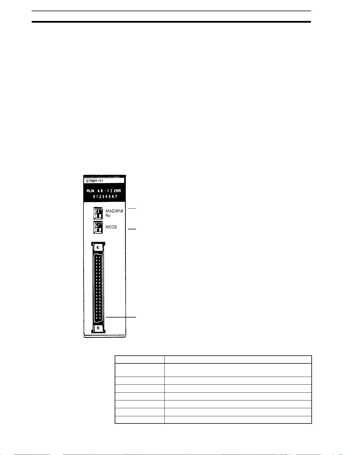
The nomenclature is the same for both the C200H-CT001-V1 and the C200HCT002. The C200H-CT001-V1 is shown below.
Indicators
Unit number switch (“Machine No.”)
Operating mode switch
I/O Connector
Connect to the input device(s) and to any outputs used.
Attach the enclosed connector to the proper cable(s).
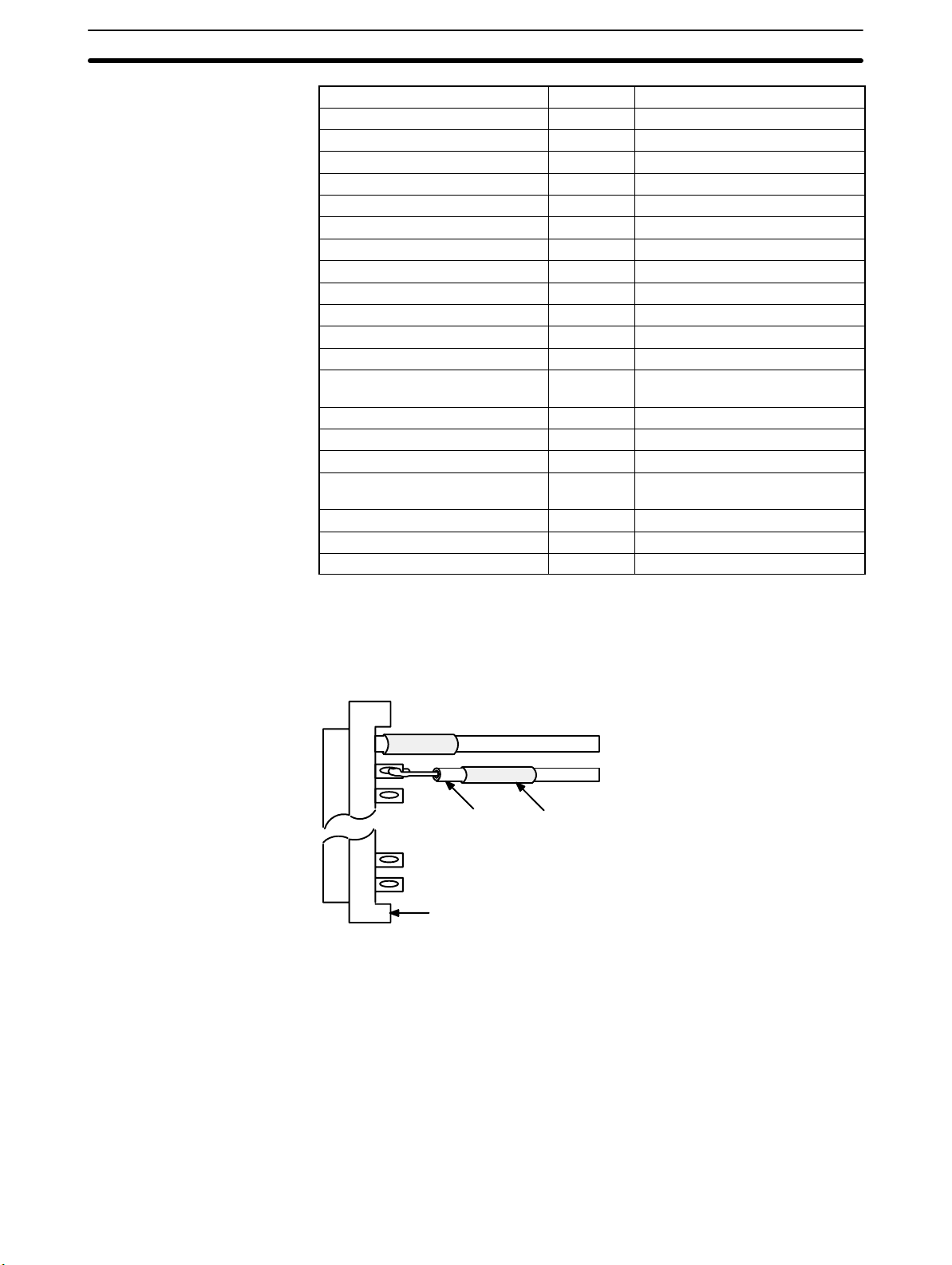
Indicator Function
RUN Lit during normal operation or when waiting for input.
Goes out for errors.
A Lit when input A is ON.
B Lit when input B is ON.
1 Lit when control input IN1 is ON.
2 Lit when control input IN2 is ON.
ERR Lit when an error has occurred.
0 to 7 Lit when corresponding output is ON.
2
System Configuration Section 1-3
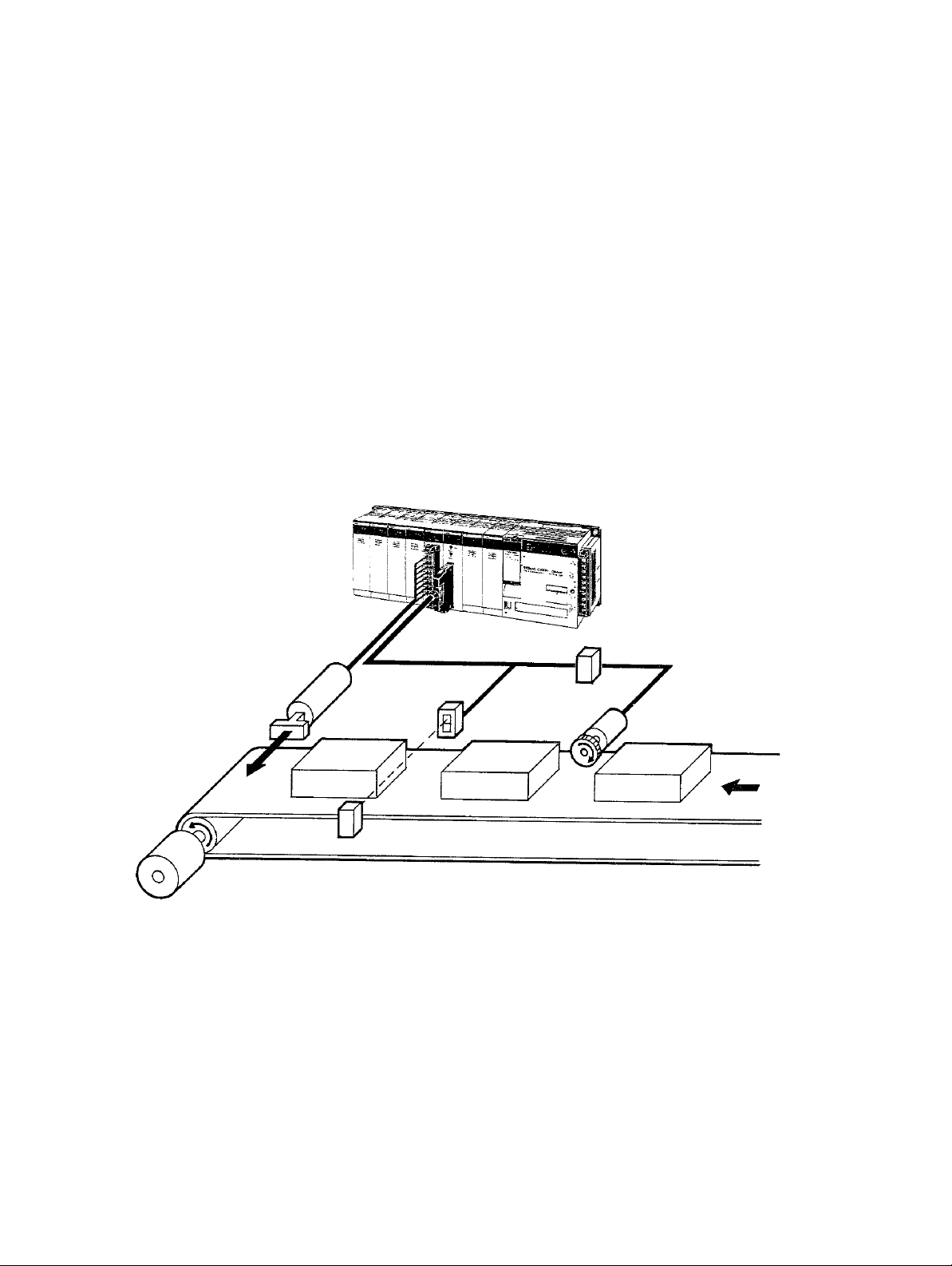
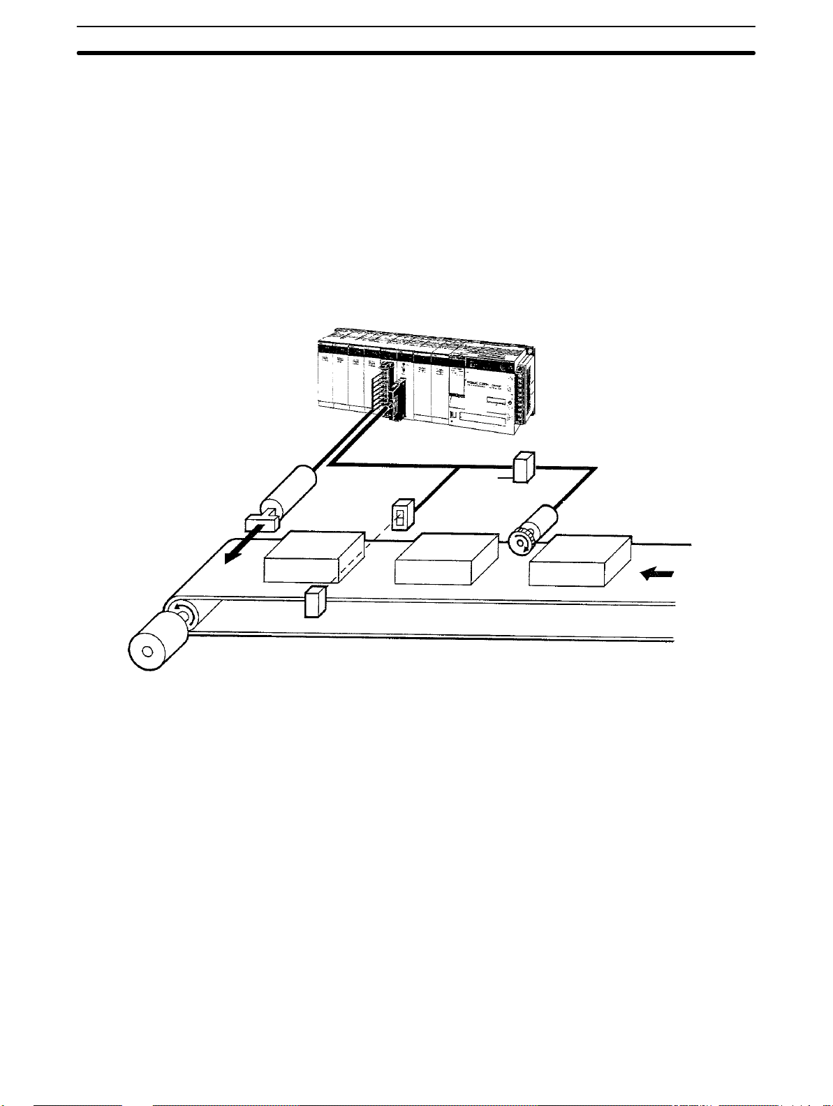
1-3 System Configuration
Example Configuration The following example system configuration uses the Counter Unit to deter-
mine whether or not product length is acceptable. The length of the products
passing by on the conveyor is measured by using the output from a photoelectric switch to initiate and end counting of pulses output from an encoder.
Product length is checked against standards and the product is ejected if it is
out of the acceptable range.
Electromagnetic solenoid
(for ejecting defective
products)
C200H-OA221
Output Unit
Photoelectric switch
(for detecting
products)
Counter Unit
SYSMAC C200H
An encoder adapter is required if
the C200H-CT002 is used with
an open-collector encoder.
Encoder
adapter
Encoder (for detecting
conveyor movement
ConveyorMotor
Many other applications are possible by combining other types of inputs and outputs. Refer to Section 4 Data Allocation and Operating Modes for other application examples.
Maximum number of
Special I/O Units per PC
A maximum of 10 Special I/O Units, including Position Control Units, Counter
Units, etc., can be mounted under the same PC, regardless of whether they
are on the CPU Rack, the Expansion I/O Rack, or the rack containing a Remote I/O Slave Unit controlled by the PC. No more than four of these can be
mounted onto any one rack containing a Remote I/O Slave Unit.
Mounting Location The Counter Unit can be mounted to any but the 2 rightmost CPU Rack slots.
Mounting the Counter Unit to either of these slots will prevent you from
mounting devices directly to the PC’s CPU.
The back panel DIP switch must be set before the Counter Unit is mounted.
(Refer to 2-1 Switch Settings.)
3

Operating Modes Section 1-4
1-4 Operating Modes
The Counter Unit can be operated in any one of the six operating modes described below. External outputs are available in only 3 modes: linear, circular,
and preset. The function of these outputs depends on the mode. (The mode is
selected using the mode selector on the front panel of the Counter Unit, as described in 2-1 Switch Settings.) The following is merely an introduction to the op-
erating modes, all of which are covered in detail in Section 4 Data Allocation and
Operating Modes.
Linear Mode In linear mode, the counter value is incremented and decremented between
–8,388,608 and 8,388,607 and is continually compared with preset ranges.
When the counter value is within a range (or ranges), specified outputs are
turned ON. The same output may be specified for one or more overlapping
ranges, in which case the output will be turned ON whenever the counter value i s
within one or more of the ranges.
A maximum of 16 ranges may be specified, each with upper and lower limits.
These limits must be within the counter range, i.e., between –8,388,608 and
8,388,607. Data can be transferred from the PC to change range limits or to set
the present counter value as desired.
Circular Mode In circular mode, the counter value restarts from zero after reaching a preset
maximum value or returns to the preset maximum value when the counter
value is decremented past zero. In all other respects, including data transfer,
circular mode functions exactly as the linear mode. The preset maximum value must be between 0 and 65,535.
Preset Mode In preset mode, the counter value is normally decremented from a preset
value (between 1 and 8,388,607) to zero, although it can also be incremented. During this decrement phase, a total of 3 outputs may be switched ON
and OFF according to ON/OFF counter values. When the counter value
reaches zero, a total of 4 outputs may be turned ON, either indefinitely or for
a preset time, T. Data can be transferred from the PC to change ON/OFF
counter values as desired.
Gate Mode Two types of gate mode operation are available on the C200H-CT002: nor-
mal and cumulative. Only the normal type is available on the C200HCT001-V1. In normal gate mode, pulses are counted while control input IN1
(the count signal) is ON. The counter value is retained when input IN1 goes
OFF until input IN1 goes ON again, at which point counting restarts from
zero. In the cumulative type, control input IN1 serves as the reset signal and
counting continues while control input IN2 (the count signal) is ON. Each time
input IN2 is turned ON, counting continues from the current counter value
until it is reset to zero by input IN1. In either type of gate mode, the counting
range is between –8,388,608 and 8,388,607 and counting may be in either
direction. This mode does not support data transfer or external outputs from
the Counter Unit.
Latch Mode In latch mode, counting begins from zero when control input IN1 (count sig-
nal) is turned ON and ranges between –8,388,608 and 8,388,607. Pulses are
counted continuously (regardless of whether input IN1 is ON or OFF) , but
the current counter value is always the counter value latched the last time
control input IN2 (the latch signal) was turned ON, i.e., the current counter
value remains unchanged while the latch signal (control input IN2) is ON and
is updated to the actual count while the latch signal is OFF. Counting may be
restarted from zero at any time be activating control input IN1. Control inputs
4

Operating Modes Section 1-4
IN1 and IN2 may originate either externally or internally. This mode does not
support external outputs from the Counter Unit or data transfer.
Sampling Mode In sampling mode, pulses are counted for a preset interval after control input
IN1 (the count signal) is turned ON. Counting may be in either direction.
Counting always begins at zero and ranges between –8,388,608 and
8,388,607. The time interval must be between 10 and 9,999 ms.
Control input IN1 may originate either externally or internally. This mode does
not support external outputs from the Counter Unit or data transfer.
5


SECTION 2
Switch Settings and Wiring
This section provides the Unit settings and connector cable pin specifications. Instructions for the construction of input
and output connectors are provided. Electrical schematics and examples are presented to further explain Unit operation.
2-1 Switch Settings 8. . . . . . . . . . . . . . . . . . . . . . . . . . . . . . . . . . . . . . . . . . . . . . . . . . . . . . . . . . .
2-2 Wiring 10. . . . . . . . . . . . . . . . . . . . . . . . . . . . . . . . . . . . . . . . . . . . . . . . . . . . . . . . . . . . . . . . . .
2-3 Input Circuit Wiring Examples 18. . . . . . . . . . . . . . . . . . . . . . . . . . . . . . . . . . . . . . . . . . . . . .
2-3-1 C200H-CT001-V1 18. . . . . . . . . . . . . . . . . . . . . . . . . . . . . . . . . . . . . . . . . . . . . . . . .
2-3-2 C200H-CT002 21. . . . . . . . . . . . . . . . . . . . . . . . . . . . . . . . . . . . . . . . . . . . . . . . . . . .
2-4 Dimensions 24. . . . . . . . . . . . . . . . . . . . . . . . . . . . . . . . . . . . . . . . . . . . . . . . . . . . . . . . . . . . . .
7

Switch Settings Section 2-1
2-1 Switch Settings
Always turn off the Counter Unit before setting the unit number and mode selectors. Use a regular screwdriver , being careful not to damage the slot in the screw.
Be sure not to leave a selector midway between settings.
Front Panel DIP Switch
Switch name Function
Unit no. Used to set the unit number. Unit numbers run from 0 through
9 and are the same for all Special I/O Units, i.e. unit number 0
may be assigned to a Position Control Unit; unit number 1, to
a High-speed Counter Unit; etc. Do not set the same number
for more than one Special I/O Unit.
Mode Used to set the operating mode. Modes run from 1 through 6,
as follows:
1: Linear 2: Circular 3: Preset
4: Gate 5: Latch 6: Sampling
8
Switch Settings Section 2-1
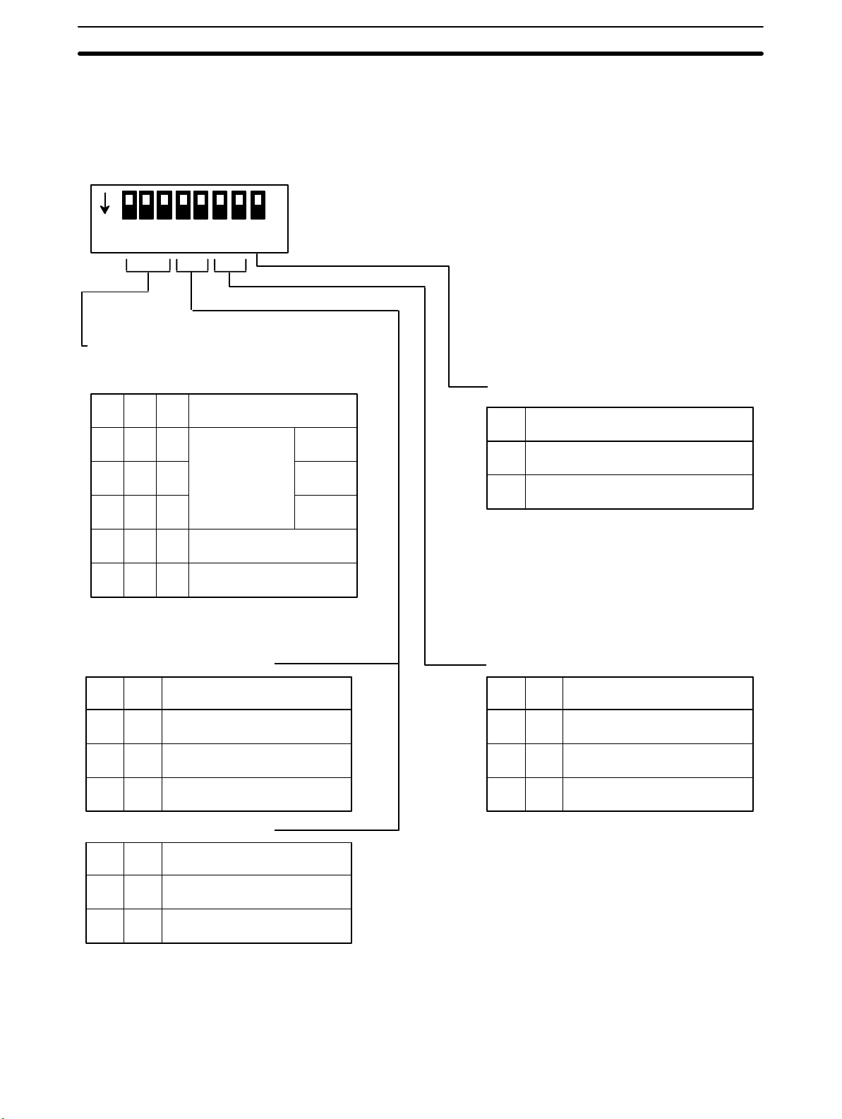
Back Panel DIP Switch
ON
12345678
Input Selection
Pins 1 through 3 are used to select the type
of inputs for inputs A and B.
1 2 3 Input type
OFF OFF OFF
Offset phases
ON
OFF
ON
*
*
Up and down pulses
OFF OFF
OFF
ON
This switch must be set before the Counter Unit is mounted. It is not necessary to set all the pins for all operating modes. Refer to 3-2 Input Selection
and Section 4 Data Allocation and Operating Modes for operational details.
Internal Reset Bit
8 Function
Normal
x2
x4
OFF Reset bit inoperative
ON Reset bit effective on rising edge.
This setting is effective only for operating
modes 1,2, and 3.
ONON
*
Pulse and direction
For Operating Mode 1 or 2: Input Z
4 5 Function
OFF Input Z inoperative*
OFFON
For Operating Mode 3: Start Input
4 5 Function
OFF
Input Z effective on falling edge.
ONON
Input Z effective on rising edge.
Start on START command
*
(IR n, bit 00).
*ON
Start on control input IN2.
Control Input IN1
6 7 Function
OFF Control input IN1 inoperative*
OFFON
This setting is effective only for operating
modes 1,2, and 3.
In modes 4, 5, and 6, control inputs IN1 and IN2
are always effective on their rising edges
Control input IN1 effective on
falling edge.
Control input IN1 effective on
ONON
rising edge.
*Pins marked with asterisks are not used.
9

Wiring Section 2-2
2-2 Wiring
Connector Pin Arrangement
C200H-CT001-V1
Names of inputs and outputs and the pin arrangement of the connector are
shown below (as viewed from the front). The connector is a Fujitsu
FCN-361J040 (solder type), and is included with the Counter Unit.
Row B Pin no. Row A
Input A: 24 VDC 20 Input A: 12 VDC
Input A: 0 V 19 Input A: 5 VDC
Input B: 24 VDC 18 Input B: 12 VDC
Input B: 0 V 17 Input B: 5 VDC
Input Z: 24 VDC 16 Input Z: 12 VDC
Input Z: 0 V 15 Input Z: 5 VDC
14
13 Control input IN1: 12/24 VDC
Control input IN1: 0 V 12 Control input IN1: 5 VDC
11 Control input IN2: 12/24 VDC
Control input IN2: 0 V 10 Control input IN2: 5 VDC
9
Outputs 0 through 3
Power supply: 5 to 24 VDC
Outputs 0 through 3, COM: 0 V 6 Output 2
Outputs 4 through 7
Power supply: 5 to 24 VDC
Outputs 4 through 7, COM: 0 V 2 Output 6
8 Output 0
7 Output 1
5 Output 3
4 Output 4
3 Output 5
1 Output 7
10
Wiring Section 2-2
C200H-CT002
Row B Pin no. Row A
20
Input A: neg. 19 Input A: pos.
18
Input B: neg. 17 Input B: pos.
16
Input Z: neg. 15 Input Z: pos.
14
13 Control input IN1: 12/24 VDC
Control input IN1: 0 V 12 Control input IN1: 5 VDC
11 Control input IN2: 12/24 VDC
Control input IN2: 0 V 10 Control input IN2: 5 VDC
9
Outputs 0 through 3
Power supply: 5 to 24 VDC
Outputs 0 through 3, COM: 0 V 6 Output 2
Outputs 4 through 7
Power supply: 5 to 24 VDC
Outputs 4 through 7, COM: 0 V 2 Output 6
8 Output 0
7 Output 1
5 Output 3
4 Output 4
3 Output 5
1 Output 7
Wiring Connectors Solder-type connectors are included with the Counter Unit.
2
Use wire with a cross-sectional area of 0.3 mm
or less. When soldering, do not
short-circuit an adjacent terminal; cover the soldered section with an insulation
tube. When using multicore cable, wire output and input cables separately.
Wire Insulation tube
Connector
11
Wiring Section 2-2
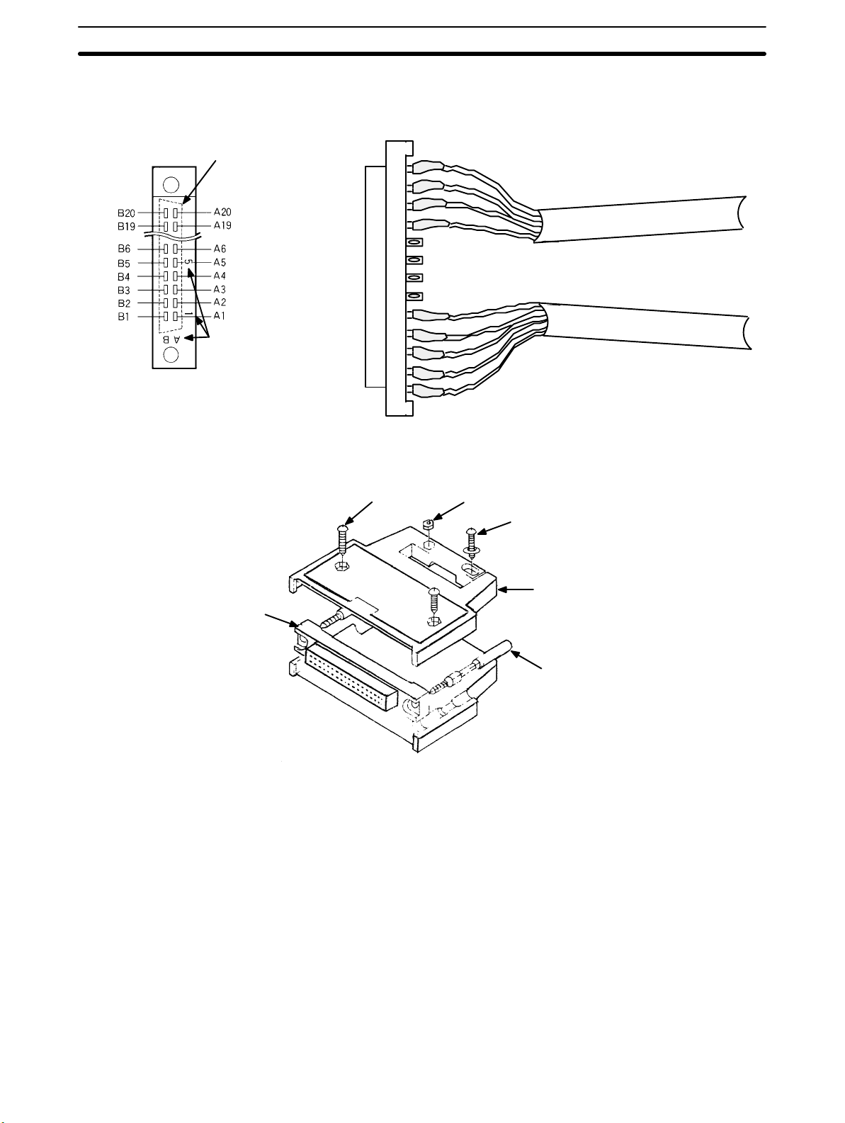
Differentiating Cables and
Connector Pin Numbers
Input and output cables can be differentiated by position, as shown on the
right below. Alignment with the connector pin numbers is also as shown on
the left below. Please make sure you are wiring to the correct pins.
Shape of connector
on the reverse side.
Pin number
marks
Connector pins as viewed
from the solder side.
Assembling Connectors Assemble connectors as shown below.
Round head screw
(8mm M2, two total)
Nut (M2, four total)
Input cables
Output cables
Round head screw
(10mm M2, two total)
Case
Connector
Lock screw
Note Any of the following connectors can be used as required by operating condi-
tions. The jack is a Fujitsu model 360.
1, 2, 3... 1. FCN-361J040 (solder-type, included with Counter Unit)
FCN-360C040-B (connector cover)
2. FCN-363J040 (crimp type, housing)
FCN-363J-AU (connector)
FCN-360C040 (connector cover)
3. FCN-367J040-A V/F (crimp type)
Wiring Precautions For the C200H-CT001-V1, the terminals that are used depend upon the pow-
er supply of inputs A, B, and Z.
For the C200H-CT002, inputs A, B, and Z must be line driver inputs
(Am26LS31-compatible). Positive and negative terminals must be wired correctly. The terminals that are used depend upon the power supply of the control
inputs. Be careful to connect to the correct terminals. Supply only one voltage for
12
Wiring Section 2-2
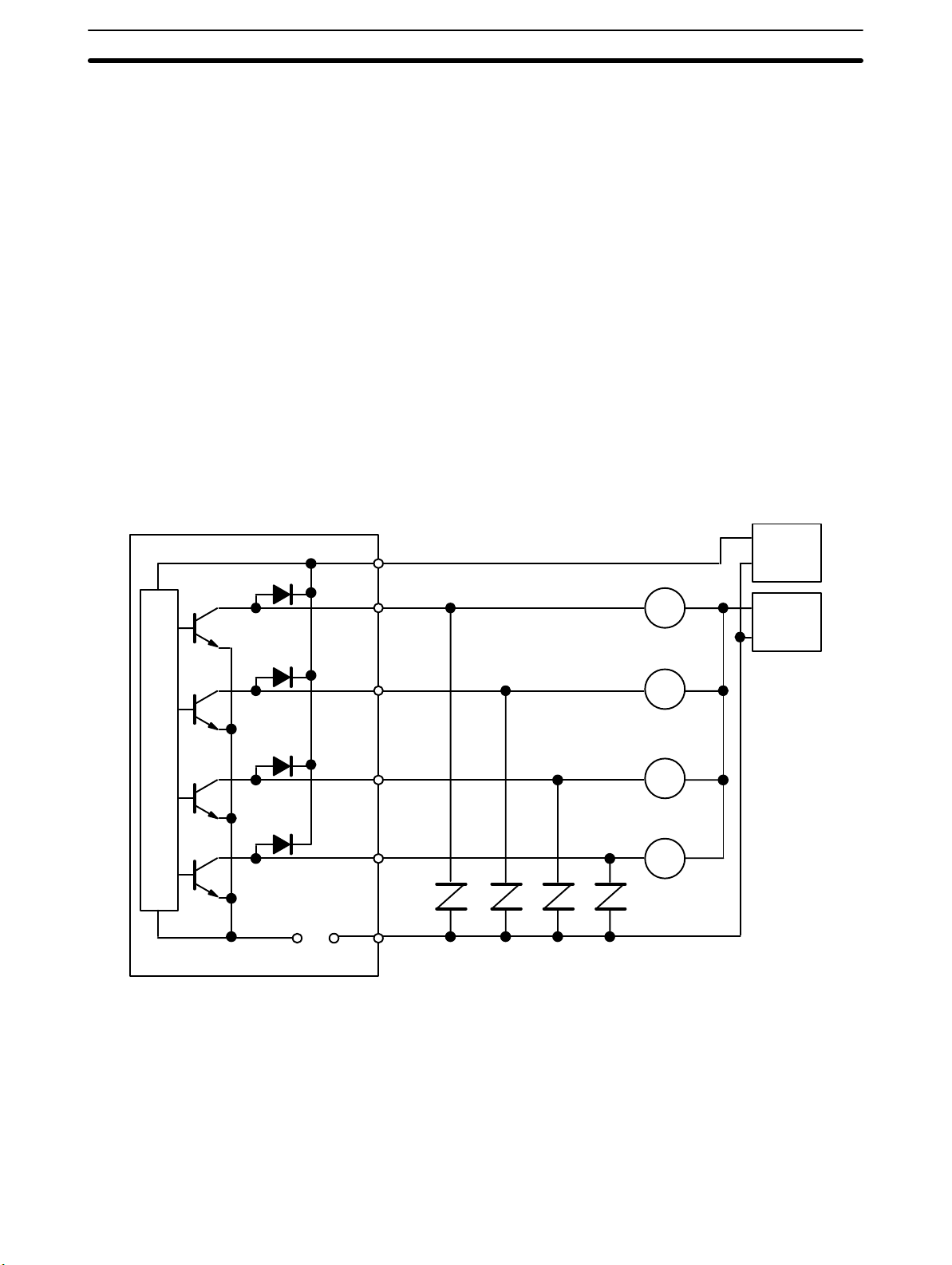
each input. The terminals for output power supply , 5 t o 2 4 VDC and COM (0 V),
are separated into two: those for outputs 0 through 7. These are not interconnected internally. If the 5 to 24 VDC and COM (0 V) terminals for the output power supply are connected incorrectly, an internal fuse will burn out, preventing operation. This fuse is not user serviceable. This fuse will also burn out if the output
current exceeds 0.5 A/common, again preventing operation. When wiring inputs
A, B, and Z, the following measures must be taken to prevent interference from
noise:
1, 2, 3... 1. Use shielded twisted pair cable and ground the shield.
2. Keep wiring as short as possible and do not place lines parallel to pos-
sible sources of noise, such as power lines.
3. Use a stabilized power supply that is independent from other input and
output power supplies.
The external power supply must be greater than or equal to the load power supply. (An error may occur if the external power supply is less than the load power
supply .) I n the example on the following page, E1 must be greater than or equal
to E2.
5 to 24 VDC
Output 0
D
r
i
v
e
c
i
rc
u
i
t
Output 1
Output 2
Output 3
Fuse COM
0.5A (0 V)
B8
A8
A7
A6
A5
B6
Counter Unit
Relay
Relay
Relay
Relay
Variable
resistors
E1
0 V
E2
0 V
~
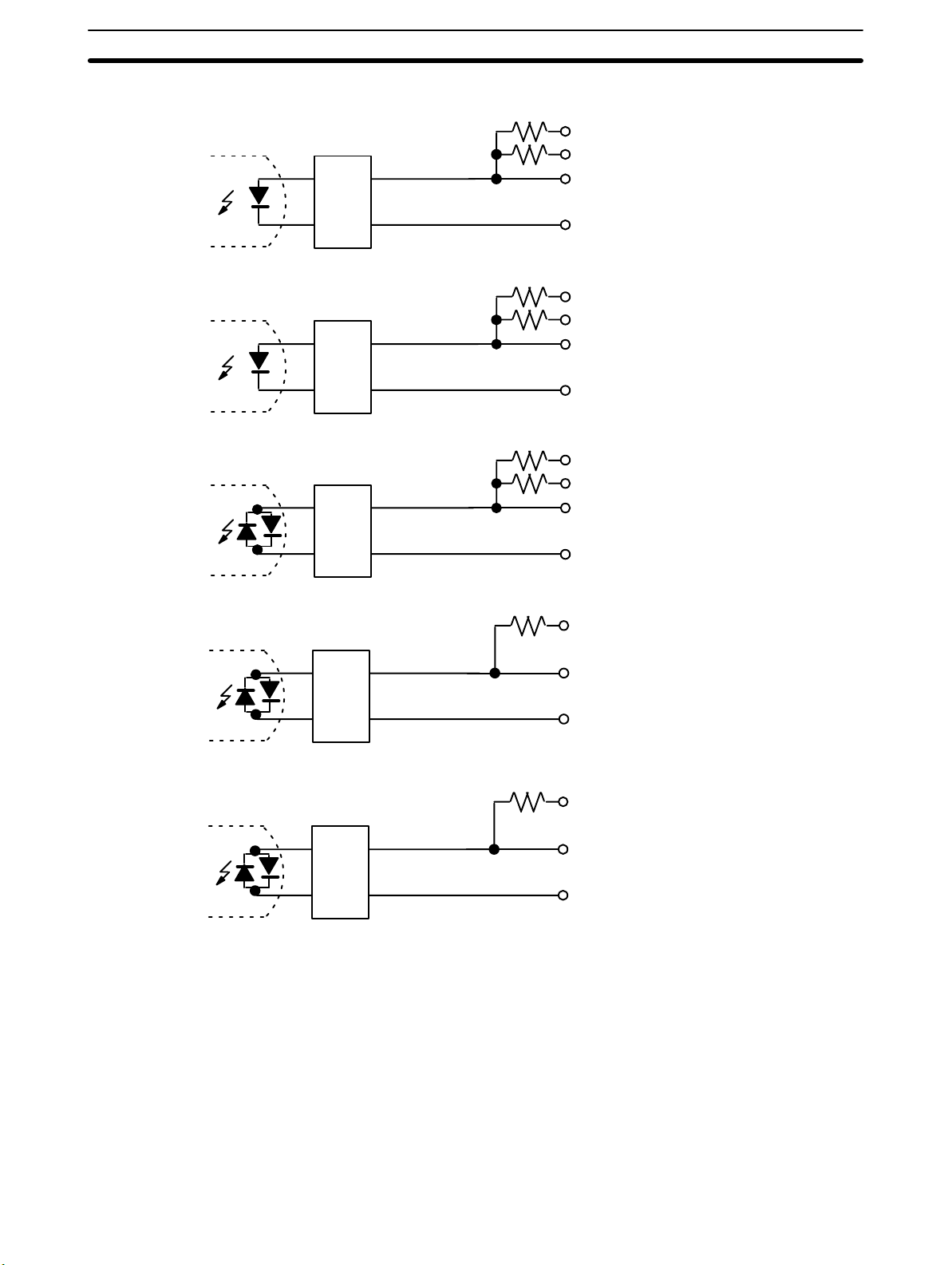
Input and Output Circuits Actual pin numbers are arranged in order from the top of the connector start-
ing with A20 and B20. For each input, connect the 0-V terminal and only one
of the other terminals, i.e., do not supply more than one voltage for any input.
The circuits are shown on the following pages.
13
Wiring Section 2-2
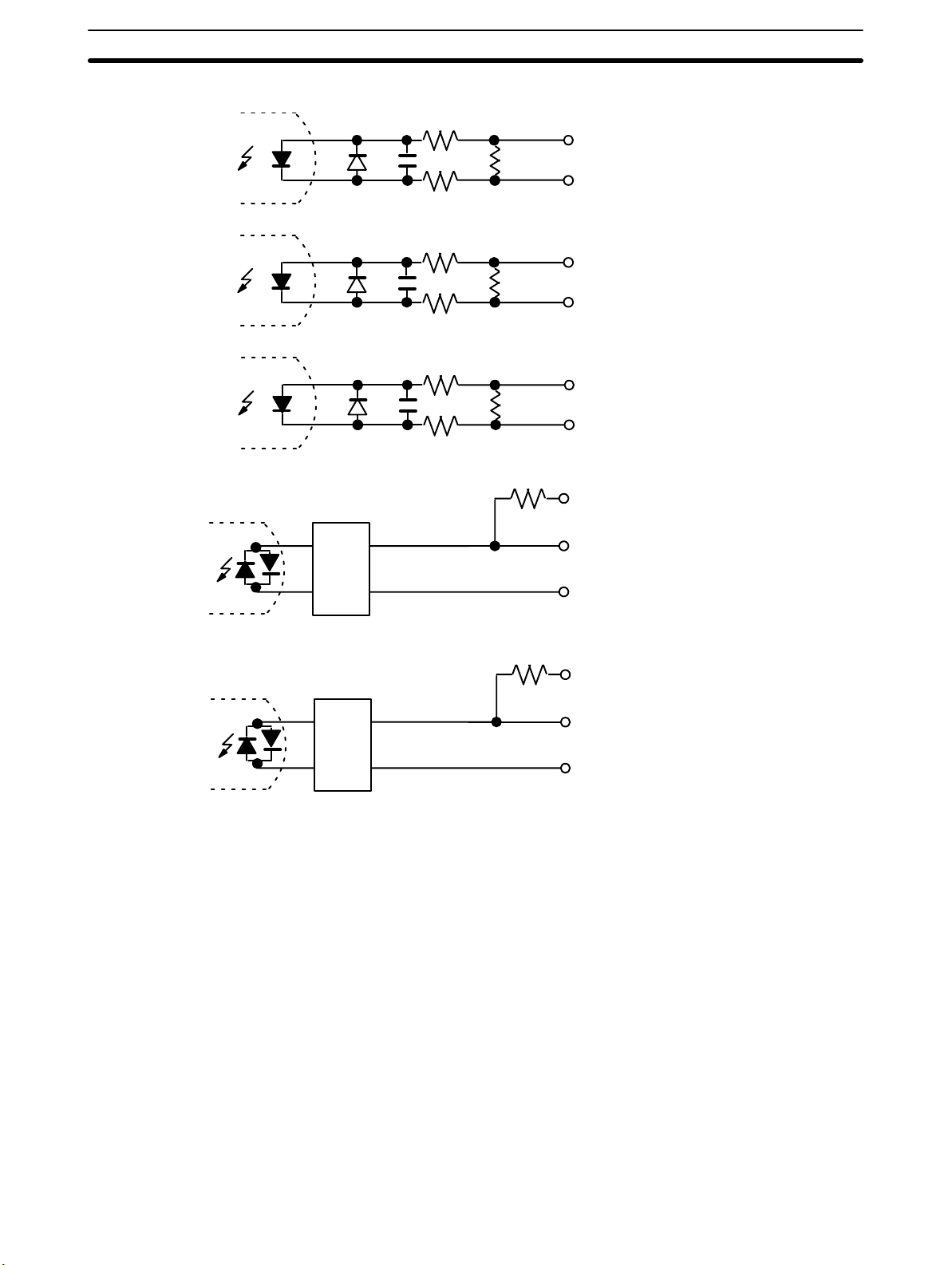
C200H-CT001-V1 Input Circuits
1.6 kΩ
B20...... Input A: 24 VDC
560 Ω
A20...... Input A: 12 VDC
A19...... Input A: 5 VDC
Rectifier
B19...... Input A: 0 V
1.6 kΩ
B18...... Input B: 24 VDC
560 Ω
A18...... Input B: 12 VDC
A17...... Input B: 5 VDC
Rectifier
B17...... Input B: 0 V
1.6 kΩ
B16...... Input Z: 24 VDC
560 Ω
A16...... Input Z: 12 VDC
A15...... Input Z: 5 VDC
Rectifier
B15...... Input Z: 0 V
Filter
Filter
1.3 kΩ
1.3 kΩ
A13......
A12......
B12......
A11......
A10......
B10......
Control input
IN1: 12/24 VDC
Control input
IN1: 5 VDC
Control input
IN1: 0 V
Control input
IN1: 12/24 VDC
Control input
IN1: 5 VDC
Control input
IN1: 0 V
14

Wiring Section 2-2
C200H-CT001-V1 Output Circuits
B8......Output power
supply: 5 to 24 VDC
A8......Output 0
A7......Output 1
A6......Output 2
Fuse
0.5 A
~
Fuse
0.5 A
~
A5......Output 3
B6......Output COM: 0 V
B4......Output power
supply: 5 to 24 VDC
A4......Output 4
A3......Output 5
A2......Output 6
A1......Output 7
B2......Output COM: 0 V
15
Wiring Section 2-2
C200H-CT002 Input Circuits
A19...... Input A: pos.
B19...... Input A: neg.
A17...... Input B: pos.
B17...... Input B: neg.
A15...... Input Z: pos.
B15...... Input Z: neg.
Filter
Filter
1.3 kΩ
1.3 kΩ
A13......
A12......
B15......
A11......
A10......
B10......
Control input
IN1: 12/24 VDC
Control input
IN1: 5 VDC
Control input
IN1: 0 V
Control input
IN1: 12/24 VDC
Control input
IN1: 5 VDC
Control input
IN1: 0 V
16
 Loading...