

Page 1

Cat.No. W141–E1–4
SYSMAC
C200H-CT001-V1/CT002
High-speed Counter Units
OPERATION MANUAL
Page 2

Page 3
C200H-CT001-V1/CT002
High-speed Counter Units
Operation Manual
Revised September 2000
Page 4

iv
Page 5

Notice:
OMRON products are manufactured for use according to proper procedures by a qualified operator
and only for the purposes described in this manual.
The following conventions are used to indicate and classify precautions in this manual. Always heed
the information provided with them. Failure to heed precautions can result in injury to people or damage to property.
DANGER Indicates an imminently hazardous situation which, if not avoided, will result in death or
!
serious injury.
WARNING Indicates a potentially hazardous situation which, if not avoided, could result in death or
!
serious injury.
Caution Indicates a potentially hazardous situation which, if not avoided, may result in minor or
!
moderate injury, or property damage.
OMRON Product References
All OMRON products are capitalized in this manual. The word “Unit” is also capitalized when it refers
to an OMRON product, regardless of whether or not it appears in the proper name of the product.
The abbreviation “Ch,” which appears in some displays and on some OMRON products, often means
“word” and is abbreviated “Wd” in documentation in this sense.
The abbreviation “PC” means Programmable Controller and is not used as an abbreviation for anything else.
Visual Aids
The following headings appear in the left column of the manual to help you locate different types of
information.
OMRON, 1990
All rights reserved. No part of this publication may be reproduced, stored in a retrieval system, or transmitted, in any
form, or by any means, mechanical, electronic, photocopying, recording, or otherwise, without the prior written permission of OMRON.
No patent liability is assumed with respect to the use of the information contained herein. Moreover, because OMRON is
constantly striving to improve its high-quality products, the information contained in this manual is subject to change
without notice. Every precaution has been taken in the preparation of this manual. Nevertheless, OMRON assumes no
responsibility for errors or omissions. Neither is any liability assumed for damages resulting from the use of the information contained in this publication.
Note Indicates information of particular interest for efficient and convenient operation
of the product.
1, 2, 3... 1. Indicates lists of one sort or another, such as procedures, checklists, etc.
v
Page 6

vi
Page 7

TABLE OF CONTENTS
PRECAUTIONS xi. . . . . . . . . . . . . . . . . . . . . . . . . . . . . . . . .
1 Intended Audience xii. . . . . . . . . . . . . . . . . . . . . . . . . . . . . . . . . . . . . . . . . . . . . . . . . . . . . . . . . . .
2 General Precautions xii. . . . . . . . . . . . . . . . . . . . . . . . . . . . . . . . . . . . . . . . . . . . . . . . . . . . . . . . . .
3 Safety Precautions xii. . . . . . . . . . . . . . . . . . . . . . . . . . . . . . . . . . . . . . . . . . . . . . . . . . . . . . . . . . .
4 Operating Environment Precautions xiii. . . . . . . . . . . . . . . . . . . . . . . . . . . . . . . . . . . . . . . . . . . . .
5 Application Precautions xiii. . . . . . . . . . . . . . . . . . . . . . . . . . . . . . . . . . . . . . . . . . . . . . . . . . . . . .
SECTION 1
Introduction 1. . . . . . . . . . . . . . . . . . . . . . . . . . . . . . . . . . . .
1-1 Introduction 2. . . . . . . . . . . . . . . . . . . . . . . . . . . . . . . . . . . . . . . . . . . . . . . . . . . . . . . . . . . .
1-2 Nomenclature 2. . . . . . . . . . . . . . . . . . . . . . . . . . . . . . . . . . . . . . . . . . . . . . . . . . . . . . . . . . .
1-3 System Configuration 3. . . . . . . . . . . . . . . . . . . . . . . . . . . . . . . . . . . . . . . . . . . . . . . . . . . . .
1-4 Operating Modes 4. . . . . . . . . . . . . . . . . . . . . . . . . . . . . . . . . . . . . . . . . . . . . . . . . . . . . . . .
SECTION 2
Switch Settings and Wiring 7. . . . . . . . . . . . . . . . . . . . . . . .
2-1 Switch Settings 8. . . . . . . . . . . . . . . . . . . . . . . . . . . . . . . . . . . . . . . . . . . . . . . . . . . . . . . . . .
2-2 Wiring 10. . . . . . . . . . . . . . . . . . . . . . . . . . . . . . . . . . . . . . . . . . . . . . . . . . . . . . . . . . . . . . . . .
2-3 Input Circuit Wiring Examples 18. . . . . . . . . . . . . . . . . . . . . . . . . . . . . . . . . . . . . . . . . . . . .
2-4 Dimensions 24. . . . . . . . . . . . . . . . . . . . . . . . . . . . . . . . . . . . . . . . . . . . . . . . . . . . . . . . . . . . .
SECTION 3
Operation 25. . . . . . . . . . . . . . . . . . . . . . . . . . . . . . . . . . . . . .
3-1 Operational Flow 26. . . . . . . . . . . . . . . . . . . . . . . . . . . . . . . . . . . . . . . . . . . . . . . . . . . . . . . .
3-2 Input Selection 26. . . . . . . . . . . . . . . . . . . . . . . . . . . . . . . . . . . . . . . . . . . . . . . . . . . . . . . . . .
3-3 Counter Reset Conditions 29. . . . . . . . . . . . . . . . . . . . . . . . . . . . . . . . . . . . . . . . . . . . . . . . .
3-4 Data Transfer Timing 30. . . . . . . . . . . . . . . . . . . . . . . . . . . . . . . . . . . . . . . . . . . . . . . . . . . . .
SECTION 4
Data Allocation and Operating Modes 33. . . . . . . . . . . . . . .
4-1 Data Configuration and Allocation 34. . . . . . . . . . . . . . . . . . . . . . . . . . . . . . . . . . . . . . . . . .
4-2 Linear and Circular Modes 36. . . . . . . . . . . . . . . . . . . . . . . . . . . . . . . . . . . . . . . . . . . . . . . .
4-3 Preset Mode 52. . . . . . . . . . . . . . . . . . . . . . . . . . . . . . . . . . . . . . . . . . . . . . . . . . . . . . . . . . . .
4-4 Gate, Latch, and Sampling Modes 63. . . . . . . . . . . . . . . . . . . . . . . . . . . . . . . . . . . . . . . . . . .
SECTION 5
Error Processing 79. . . . . . . . . . . . . . . . . . . . . . . . . . . . . . . .
5-1 Error Indications 80. . . . . . . . . . . . . . . . . . . . . . . . . . . . . . . . . . . . . . . . . . . . . . . . . . . . . . . . .
5-2 Troubleshooting from the PC 80. . . . . . . . . . . . . . . . . . . . . . . . . . . . . . . . . . . . . . . . . . . . . . .
Appendices
A Error Codes 83. . . . . . . . . . . . . . . . . . . . . . . . . . . . . . . . . . . . . . . . . . . . . . . . . . . . . . . . . . . . . . .
B Specifications 85. . . . . . . . . . . . . . . . . . . . . . . . . . . . . . . . . . . . . . . . . . . . . . . . . . . . . . . . . . . . . .
C IR Area Allocations 89. . . . . . . . . . . . . . . . . . . . . . . . . . . . . . . . . . . . . . . . . . . . . . . . . . . . . . . . .
D DM Area Coding Sheets 91. . . . . . . . . . . . . . . . . . . . . . . . . . . . . . . . . . . . . . . . . . . . . . . . . . . . .
Index 93. . . . . . . . . . . . . . . . . . . . . . . . . . . . . . . . . . . . . . . . . .
Revision History 97. . . . . . . . . . . . . . . . . . . . . . . . . . . . . . . . .
vii
Page 8

Page 9

About this Manual:
This manual covers specifications and procedures necessary for the installation and operation of the
C200H-CT001-V1 and C200H-CT002 High-speed Counter Units. It includes example system configurations to ease the implementation cycle. The C200H-CT001-V1 and C200H-CT002 are Special I/O
Units for C200H PCs. The C200H-CT001-V1 is a high-speed, reversible counter capable of counting
at a maximum of 50 kcps. The C200H-CT002 is a high-speed, reversible counter capable of counting
at a maximum of 75 kcps.
Please read this manual carefully and be sure you understand the information provided before attempting
to install and operate the C200H-CT001-V1 and C200H-CT002 High-speed Counter Units.
Section 1 contains a brief description of the Units and how they can be used. The Units are displayed
and their indicators are explained. An example system configuration is included to demonstrate Unit
application. The operating modes and their associated ranges of operation are also described.
Section 2 shows the Unit settings and connector cable pin specifications. Instructions for the construction of input and output connectors are provided. Electrical schematics and examples are presented to further explain Unit operation.
Section 3 describes the operational flow of the counting system. The input types are identified along
with instructions for their use. Data transfer timing is described in relation to the PC cycle time.
Section 4 describes the various operating modes in detail. Each mode is described by data allocation, timing charts, commands, flags, and examples. Data formats are explained.
Section 5 presents possible errors and solutions and describes how to handle errors from the PC.
The AR area Error and Restart Flags are described.
The following Appendices are also provided: Error Codes, Specifications, IR Area Allocations, and
DM Area Coding Sheets.
!
WARNING Failure to read and understand the information provided in this manual may result in
personal injury or death, damage to the product, or product failure. Please read each
section in its entirety and be sure you understand the information provided in the section
and related sections before attempting any of the procedures or operations given.
ix
Page 10

Page 11

PRECAUTIONS
This section provides general precautions for using C200H-CT001-V1/CT002 High-speed Counter Units and related
devices.
The information contained in this section is important for the safe and reliable application of the C200HCT001-V1/CT002 High-speed Counter Units. You must read this section and understand the information contained
before attempting to set up or operate a C200H-CT001-V1/CT002 High-speed Counter Unit.
1 Intended Audience xii. . . . . . . . . . . . . . . . . . . . . . . . . . . . . . . . . . . . . . . . . . . . . . . . . . . . . . . . . . . .
2 General Precautions xii. . . . . . . . . . . . . . . . . . . . . . . . . . . . . . . . . . . . . . . . . . . . . . . . . . . . . . . . . . .
3 Safety Precautions xii. . . . . . . . . . . . . . . . . . . . . . . . . . . . . . . . . . . . . . . . . . . . . . . . . . . . . . . . . . . .
4 Operating Environment Precautions xiii. . . . . . . . . . . . . . . . . . . . . . . . . . . . . . . . . . . . . . . . . . . . . .
5 Application Precautions xiii. . . . . . . . . . . . . . . . . . . . . . . . . . . . . . . . . . . . . . . . . . . . . . . . . . . . . . . .
xi
Page 12

1 Intended Audience
This manual is intended for the following personnel, who must also have knowledge of electrical systems (an electrical engineer or the equivalent).
• Personnel in charge of installing FA systems.
• Personnel in charge of designing FA systems.
• Personnel in charge of managing FA systems and facilities.
2 General Precautions
The user must operate the product according to the performance specifications
described in the relevant manuals.
Before using the product under conditions which are not described in the manual
or applying the product to nuclear control systems, railroad systems, aviation
systems, vehicles, combustion systems, medical equipment, amusement machines, safety equipment, and other systems, machines, and equipment that
may have a serious influence on lives and property if used improperly, consult
your OMRON representative.
Make sure that the ratings and performance characteristics of the product are
sufficient for the systems, machines, and equipment, and be sure to provide the
systems, machines, and equipment with double safety mechanisms.
This manual provides information for programming and operating the Unit. Be
sure to read this manual before attempting to use the Unit and keep this manual
close at hand for reference during operation.
3Safety Precautions
WARNING It is extremely important that a PC and all PC Units be used for the specified
!
purpose and under the specified conditions, especially in applications that can
directly or indirectly affect human life. You must consult with your OMRON
representative before applying a PC system to the above-mentioned
applications.
3 Safety Precautions
WARNING Do not attempt to take any Unit apart while the power is being supplied. Doing so
!
may result in electric shock.
WARNING Do not touch any of the terminals or terminal blocks while the power is being
!
supplied. Doing so may result in electric shock.
WARNING Do not attempt to disassemble, repair, or modify any Units. Any attempt to do so
!
may result in malfunction, fire, or electric shock.
xii
Page 13

4 Operating Environment Precautions
Caution Do not operate the control system in the following locations:
!
• Locations subject to direct sunlight.
• Locations subject to temperatures or humidity outside the range specified in
the specifications.
• Locations subject to condensation as the result of severe changes in temperature.
• Locations subject to corrosive or flammable gases.
• Locations subject to dust (especially iron dust) or salts.
• Locations subject to exposure to water, oil, or chemicals.
• Locations subject to shock or vibration.
Caution Take appropriate and sufficient countermeasures when installing systems in the
!
following locations:
• Locations subject to static electricity or other forms of noise.
• Locations subject to strong electromagnetic fields.
• Locations subject to possible exposure to radioactivity.
• Locations close to power supplies.
5Application Precautions
Caution The operating environment of the PC system can have a large effect on the lon-
!
gevity and reliability of the system. Improper operating environments can lead to
malfunction, failure, and other unforeseeable problems with the PC system. Be
sure that the operating environment is within the specified conditions at installation and remains within the specified conditions during the life of the system.
5 Application Precautions
Observe the following precautions when using the PC system.
WARNING Always heed these precautions. Failure to abide by the following precautions
!
could lead to serious or possibly fatal injury.
• Always ground the system to 100 Ω or less when installing the Units. Not connecting to a ground of 100 Ω or less may result in electric shock.
• Always turn OFF the power supply to the PC before attempting any of the following. Not turning OFF the power supply may result in malfunction or electric
shock.
• Mounting or dismounting Power Supply Units, I/O Units, CPU Units,
Memory Units, or any other Units.
• Assembling the Units.
• Setting DIP switches or rotary switches.
• Connecting cables or wiring the system.
• Connecting or disconnecting the connectors.
Caution Failure to abide by the following precautions could lead to faulty operation of the
!
PC or the system, or could damage the PC or PC Units. Always heed these precautions.
• Fail-safe measures must be taken by the customer to ensure safety in the
event of incorrect, missing, or abnormal signals caused by broken signal lines,
momentary power interruptions, or other causes.
xiii
Page 14

• Interlock circuits, limit circuits, and similar safety measures in external circuits
(i.e., not in the Programmable Controller) must be provided by the customer.
• Always use the power supply voltages specified in this manual. An incorrect
voltage may result in malfunction or burning.
• Take appropriate measures to ensure that the specified power with the rated
voltage and frequency is supplied. Be particularly careful in places where the
power supply is unstable. An incorrect power supply may result in malfunction.
• Install external breakers and take other safety measures against short-circuiting in external wiring. Insufficient safety measures against short-circuiting may
result in burning.
• Do not apply voltages to the Input Units in excess of the rated input voltage.
Excess voltages may result in burning.
• Do not apply voltages or connect loads to the Output Units in excess of the
maximum switching capacity. Excess voltage or loads may result in burning.
• Disconnect the functional ground terminal when performing withstand voltage
tests. Not disconnecting the functional ground terminal may result in burning.
• Be sure that all the mounting screws, terminal screws, and cable connector
screws are tightened to the torque specified in this manual. Incorrect tightening torque may result in malfunction.
• Leave the label attached to the Unit when wiring. Removing the label may result in malfunction if foreign matter enters the Unit.
• Remove the label after the completion of wiring to ensure proper heat dissipation. Leaving the label attached may result in malfunction.
• Double-check all wiring and switch settings before turning ON the power supply. Incorrect wiring may result in burning.
• Wire correctly. Incorrect wiring may result in burning.
• Mount Units only after checking terminal blocks and connectors completely.
• Be sure that the terminal blocks, Memory Units, expansion cables, and other
items with locking devices are properly locked into place. Improper locking
may result in malfunction.
• Check the user program for proper execution before actually running it on the
Unit. Not checking the program may result in an unexpected operation.
• Confirm that no adverse effect will occur in the system before attempting any of
the following. Not doing so may result in an unexpected operation.
• Changing the operating mode of the PC.
• Force-setting/force-resetting any bit in memory.
• Changing the present value of any word or any set value in memory.
• Resume operation only after transferring to the new CPU Unit the contents of
the DM Area, HR Area, and other data required for resuming operation. Not
doing so may result in an unexpected operation.
• Do not pull on the cables or bend the cables beyond their natural limit. Doing
either of these may break the cables.
• Do not place objects on top of the cables or other wiring lines. Doing so may
break the cables.
• Use crimp terminals for wiring. Do not connect bare stranded wires directly to
terminals. Connection of bare stranded wires may result in burning.
• When replacing parts, be sure to confirm that the rating of a new part is correct.
Not doing so may result in malfunction or burning.
• Before touching a Unit, be sure to first touch a grounded metallic object in order
to discharge any static built-up. Not doing so may result in malfunction or damage.
5Application Precautions
xiv
Page 15

SECTION 1
Introduction
This section introduces the High-speed Counter Unit. It starts by describing Unit nomenclature and then describes the
type of system the Units are generally incorporated it. This section ends with an introduction to the six operating modes,
which are described in more detail in Section 4.
1-1 Introduction 2. . . . . . . . . . . . . . . . . . . . . . . . . . . . . . . . . . . . . . . . . . . . . . . . . . . . . . . . . . . . .
1-2 Nomenclature 2. . . . . . . . . . . . . . . . . . . . . . . . . . . . . . . . . . . . . . . . . . . . . . . . . . . . . . . . . . . .
1-3 System Configuration 3. . . . . . . . . . . . . . . . . . . . . . . . . . . . . . . . . . . . . . . . . . . . . . . . . . . . . .
1-4 Operating Modes 4. . . . . . . . . . . . . . . . . . . . . . . . . . . . . . . . . . . . . . . . . . . . . . . . . . . . . . . . .
1
Page 16
Nomenclature Section 1-2
1-1 Introduction
The C200H-CT001-V1 and C200H-CT002 are Special I/O Units for C200H PCs.
The C200H-CT001-V1 can be connected directly to an incremental encoder
with an open-collector output or source output to function as a high-speed, reversible counter capable of counting at a maximum of 50 kcps.
The C200H-CT002 can be connected directly to an incremental encoder with an
RS-422 line driver output or through an Encoder Adapter to an incremental encoder with a open-collector output to function as a high-speed, reversible counter capable of counting at a maximum of 75 kcps.
The C200H-CT002 is more resistive to noise than the C200H-CT001-V1 and
should be used wherever excessive cable length or a noise-prone environment
is anticipated. Unless otherwise specified, all information presented applies to
both High-Speed Counter Units. Both the High-Speed Counter Units are referred to generically as the Counter Unit.
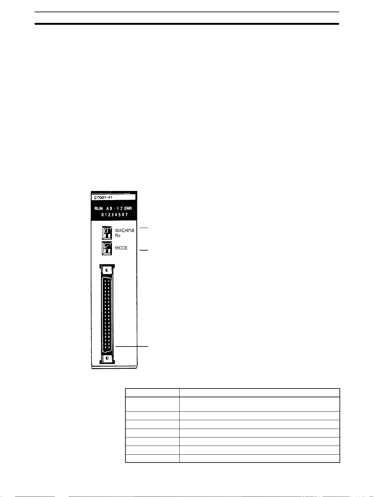
1-2 Nomenclature
The nomenclature is the same for both the C200H-CT001-V1 and the C200HCT002. The C200H-CT001-V1 is shown below.
Indicators
Unit number switch (“Machine No.”)
Operating mode switch
I/O Connector
Connect to the input device(s) and to any outputs used.
Attach the enclosed connector to the proper cable(s).
Indicator Function
RUN Lit during normal operation or when waiting for input.
Goes out for errors.
A Lit when input A is ON.
B Lit when input B is ON.
1 Lit when control input IN1 is ON.
2 Lit when control input IN2 is ON.
ERR Lit when an error has occurred.
0 to 7 Lit when corresponding output is ON.
2
Page 17
System Configuration Section 1-3
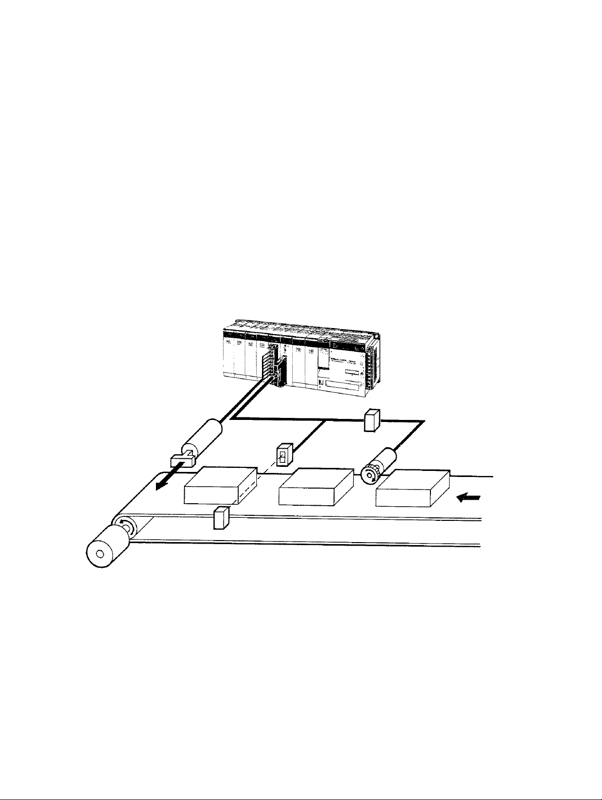
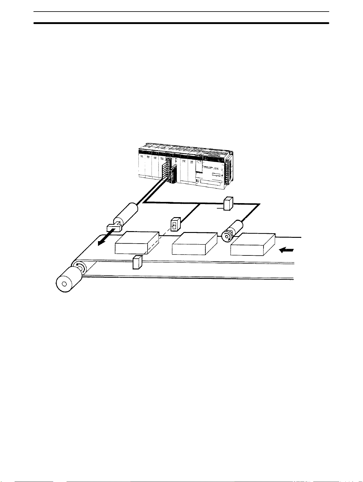
1-3 System Configuration
Example Configuration The following example system configuration uses the Counter Unit to deter-
mine whether or not product length is acceptable. The length of the products
passing by on the conveyor is measured by using the output from a photoelectric switch to initiate and end counting of pulses output from an encoder.
Product length is checked against standards and the product is ejected if it is
out of the acceptable range.
Electromagnetic solenoid
(for ejecting defective
products)
C200H-OA221
Output Unit
Photoelectric switch
(for detecting
products)
Counter Unit
SYSMAC C200H
An encoder adapter is required if
the C200H-CT002 is used with
an open-collector encoder.
Encoder
adapter
Encoder (for detecting
conveyor movement
ConveyorMotor
Many other applications are possible by combining other types of inputs and outputs. Refer to Section 4 Data Allocation and Operating Modes for other application examples.
Maximum number of
Special I/O Units per PC
A maximum of 10 Special I/O Units, including Position Control Units, Counter
Units, etc., can be mounted under the same PC, regardless of whether they
are on the CPU Rack, the Expansion I/O Rack, or the rack containing a Remote I/O Slave Unit controlled by the PC. No more than four of these can be
mounted onto any one rack containing a Remote I/O Slave Unit.
Mounting Location The Counter Unit can be mounted to any but the 2 rightmost CPU Rack slots.
Mounting the Counter Unit to either of these slots will prevent you from
mounting devices directly to the PC’s CPU.
The back panel DIP switch must be set before the Counter Unit is mounted.
(Refer to 2-1 Switch Settings.)
3
Page 18

Operating Modes Section 1-4
1-4 Operating Modes
The Counter Unit can be operated in any one of the six operating modes described below. External outputs are available in only 3 modes: linear, circular,
and preset. The function of these outputs depends on the mode. (The mode is
selected using the mode selector on the front panel of the Counter Unit, as described in 2-1 Switch Settings.) The following is merely an introduction to the op-
erating modes, all of which are covered in detail in Section 4 Data Allocation and
Operating Modes.
Linear Mode In linear mode, the counter value is incremented and decremented between
–8,388,608 and 8,388,607 and is continually compared with preset ranges.
When the counter value is within a range (or ranges), specified outputs are
turned ON. The same output may be specified for one or more overlapping
ranges, in which case the output will be turned ON whenever the counter value i s
within one or more of the ranges.
A maximum of 16 ranges may be specified, each with upper and lower limits.
These limits must be within the counter range, i.e., between –8,388,608 and
8,388,607. Data can be transferred from the PC to change range limits or to set
the present counter value as desired.
Circular Mode In circular mode, the counter value restarts from zero after reaching a preset
maximum value or returns to the preset maximum value when the counter
value is decremented past zero. In all other respects, including data transfer,
circular mode functions exactly as the linear mode. The preset maximum value must be between 0 and 65,535.
Preset Mode In preset mode, the counter value is normally decremented from a preset
value (between 1 and 8,388,607) to zero, although it can also be incremented. During this decrement phase, a total of 3 outputs may be switched ON
and OFF according to ON/OFF counter values. When the counter value
reaches zero, a total of 4 outputs may be turned ON, either indefinitely or for
a preset time, T. Data can be transferred from the PC to change ON/OFF
counter values as desired.
Gate Mode Two types of gate mode operation are available on the C200H-CT002: nor-
mal and cumulative. Only the normal type is available on the C200HCT001-V1. In normal gate mode, pulses are counted while control input IN1
(the count signal) is ON. The counter value is retained when input IN1 goes
OFF until input IN1 goes ON again, at which point counting restarts from
zero. In the cumulative type, control input IN1 serves as the reset signal and
counting continues while control input IN2 (the count signal) is ON. Each time
input IN2 is turned ON, counting continues from the current counter value
until it is reset to zero by input IN1. In either type of gate mode, the counting
range is between –8,388,608 and 8,388,607 and counting may be in either
direction. This mode does not support data transfer or external outputs from
the Counter Unit.
Latch Mode In latch mode, counting begins from zero when control input IN1 (count sig-
nal) is turned ON and ranges between –8,388,608 and 8,388,607. Pulses are
counted continuously (regardless of whether input IN1 is ON or OFF) , but
the current counter value is always the counter value latched the last time
control input IN2 (the latch signal) was turned ON, i.e., the current counter
value remains unchanged while the latch signal (control input IN2) is ON and
is updated to the actual count while the latch signal is OFF. Counting may be
restarted from zero at any time be activating control input IN1. Control inputs
4
Page 19

Operating Modes Section 1-4
IN1 and IN2 may originate either externally or internally. This mode does not
support external outputs from the Counter Unit or data transfer.
Sampling Mode In sampling mode, pulses are counted for a preset interval after control input
IN1 (the count signal) is turned ON. Counting may be in either direction.
Counting always begins at zero and ranges between –8,388,608 and
8,388,607. The time interval must be between 10 and 9,999 ms.
Control input IN1 may originate either externally or internally. This mode does
not support external outputs from the Counter Unit or data transfer.
5
Page 20

Page 21

SECTION 2
Switch Settings and Wiring
This section provides the Unit settings and connector cable pin specifications. Instructions for the construction of input
and output connectors are provided. Electrical schematics and examples are presented to further explain Unit operation.
2-1 Switch Settings 8. . . . . . . . . . . . . . . . . . . . . . . . . . . . . . . . . . . . . . . . . . . . . . . . . . . . . . . . . . .
2-2 Wiring 10. . . . . . . . . . . . . . . . . . . . . . . . . . . . . . . . . . . . . . . . . . . . . . . . . . . . . . . . . . . . . . . . . .
2-3 Input Circuit Wiring Examples 18. . . . . . . . . . . . . . . . . . . . . . . . . . . . . . . . . . . . . . . . . . . . . .
2-3-1 C200H-CT001-V1 18. . . . . . . . . . . . . . . . . . . . . . . . . . . . . . . . . . . . . . . . . . . . . . . . .
2-3-2 C200H-CT002 21. . . . . . . . . . . . . . . . . . . . . . . . . . . . . . . . . . . . . . . . . . . . . . . . . . . .
2-4 Dimensions 24. . . . . . . . . . . . . . . . . . . . . . . . . . . . . . . . . . . . . . . . . . . . . . . . . . . . . . . . . . . . . .
7
Page 22

Switch Settings Section 2-1
2-1 Switch Settings
Always turn off the Counter Unit before setting the unit number and mode selectors. Use a regular screwdriver , being careful not to damage the slot in the screw.
Be sure not to leave a selector midway between settings.
Front Panel DIP Switch
Switch name Function
Unit no. Used to set the unit number. Unit numbers run from 0 through
9 and are the same for all Special I/O Units, i.e. unit number 0
may be assigned to a Position Control Unit; unit number 1, to
a High-speed Counter Unit; etc. Do not set the same number
for more than one Special I/O Unit.
Mode Used to set the operating mode. Modes run from 1 through 6,
as follows:
1: Linear 2: Circular 3: Preset
4: Gate 5: Latch 6: Sampling
8
Page 23
Switch Settings Section 2-1
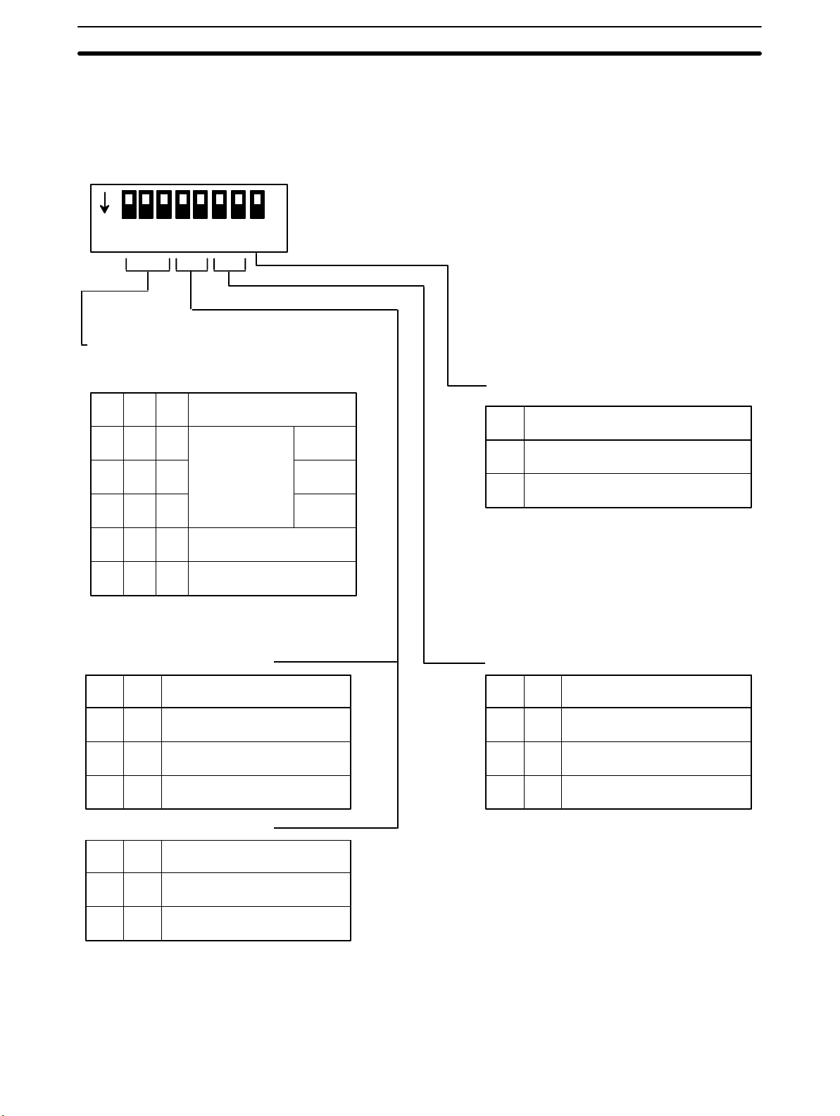
Back Panel DIP Switch
ON
12345678
Input Selection
Pins 1 through 3 are used to select the type
of inputs for inputs A and B.
1 2 3 Input type
OFF OFF OFF
Offset phases
ON
OFF
ON
*
*
Up and down pulses
OFF OFF
OFF
ON
This switch must be set before the Counter Unit is mounted. It is not necessary to set all the pins for all operating modes. Refer to 3-2 Input Selection
and Section 4 Data Allocation and Operating Modes for operational details.
Internal Reset Bit
8 Function
Normal
x2
x4
OFF Reset bit inoperative
ON Reset bit effective on rising edge.
This setting is effective only for operating
modes 1,2, and 3.
ONON
*
Pulse and direction
For Operating Mode 1 or 2: Input Z
4 5 Function
OFF Input Z inoperative*
OFFON
For Operating Mode 3: Start Input
4 5 Function
OFF
Input Z effective on falling edge.
ONON
Input Z effective on rising edge.
Start on START command
*
(IR n, bit 00).
*ON
Start on control input IN2.
Control Input IN1
6 7 Function
OFF Control input IN1 inoperative*
OFFON
This setting is effective only for operating
modes 1,2, and 3.
In modes 4, 5, and 6, control inputs IN1 and IN2
are always effective on their rising edges
Control input IN1 effective on
falling edge.
Control input IN1 effective on
ONON
rising edge.
*Pins marked with asterisks are not used.
9
Page 24
Wiring Section 2-2
2-2 Wiring
Connector Pin Arrangement
C200H-CT001-V1
Names of inputs and outputs and the pin arrangement of the connector are
shown below (as viewed from the front). The connector is a Fujitsu
FCN-361J040 (solder type), and is included with the Counter Unit.
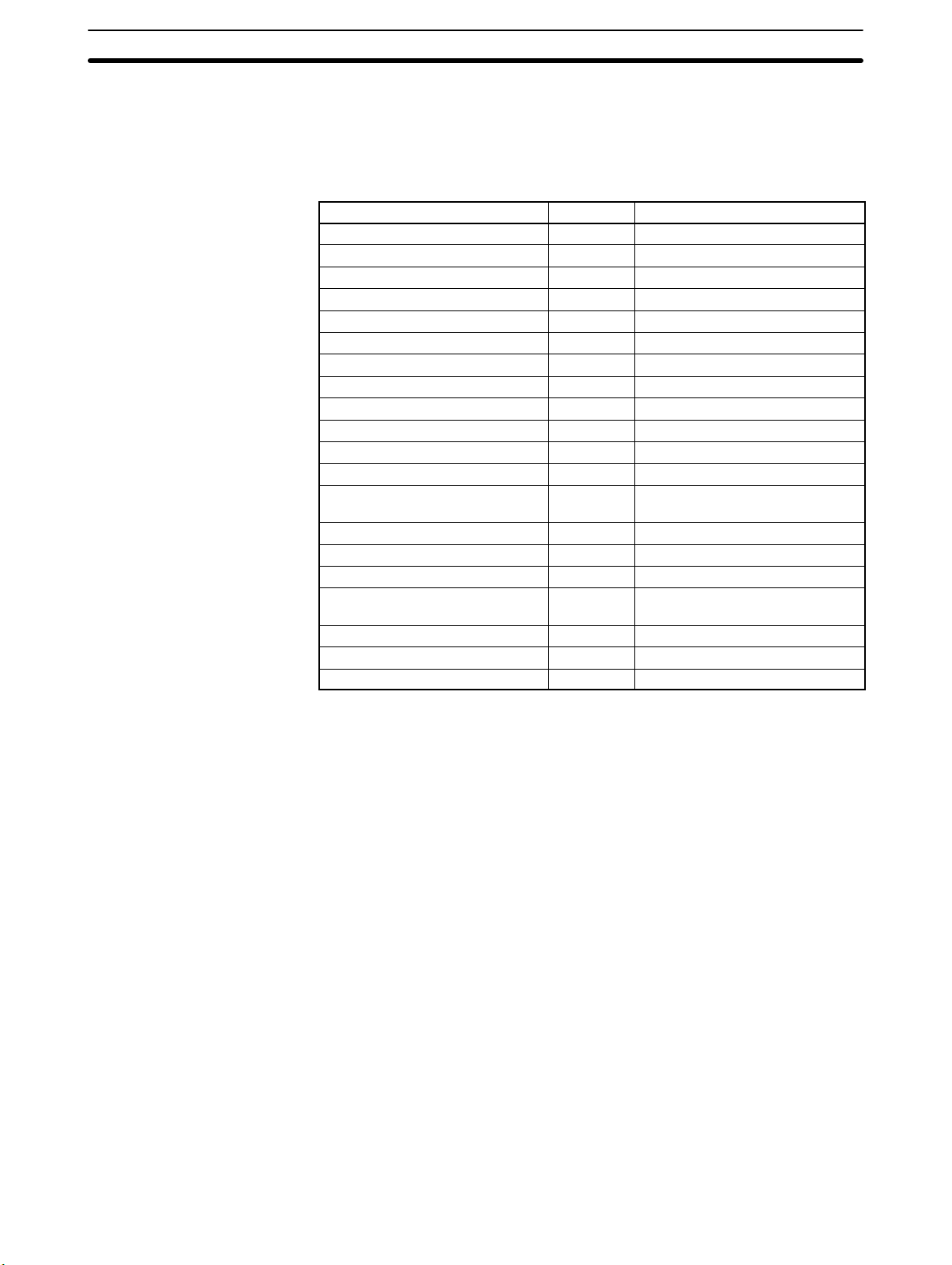
Row B Pin no. Row A
Input A: 24 VDC 20 Input A: 12 VDC
Input A: 0 V 19 Input A: 5 VDC
Input B: 24 VDC 18 Input B: 12 VDC
Input B: 0 V 17 Input B: 5 VDC
Input Z: 24 VDC 16 Input Z: 12 VDC
Input Z: 0 V 15 Input Z: 5 VDC
14
13 Control input IN1: 12/24 VDC
Control input IN1: 0 V 12 Control input IN1: 5 VDC
11 Control input IN2: 12/24 VDC
Control input IN2: 0 V 10 Control input IN2: 5 VDC
9
Outputs 0 through 3
Power supply: 5 to 24 VDC
Outputs 0 through 3, COM: 0 V 6 Output 2
Outputs 4 through 7
Power supply: 5 to 24 VDC
Outputs 4 through 7, COM: 0 V 2 Output 6
8 Output 0
7 Output 1
5 Output 3
4 Output 4
3 Output 5
1 Output 7
10
Page 25
Wiring Section 2-2
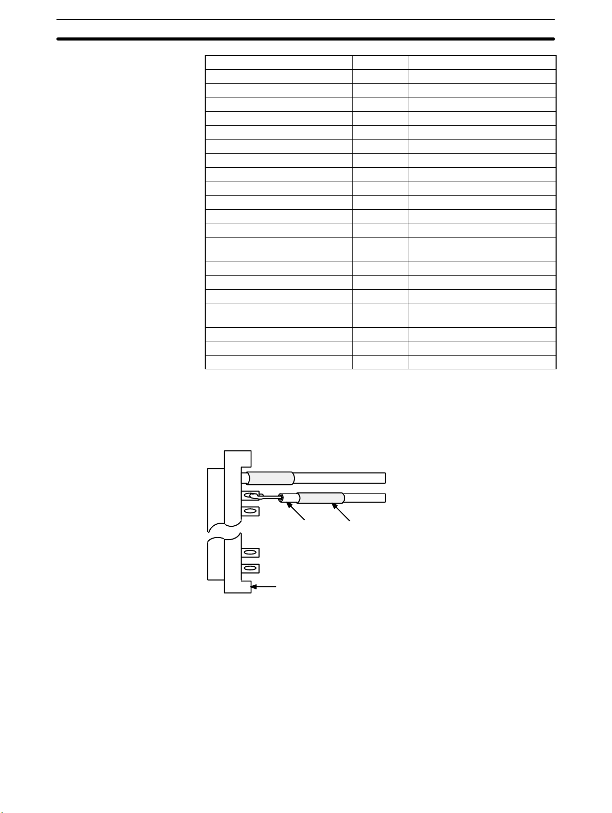
C200H-CT002
Row B Pin no. Row A
20
Input A: neg. 19 Input A: pos.
18
Input B: neg. 17 Input B: pos.
16
Input Z: neg. 15 Input Z: pos.
14
13 Control input IN1: 12/24 VDC
Control input IN1: 0 V 12 Control input IN1: 5 VDC
11 Control input IN2: 12/24 VDC
Control input IN2: 0 V 10 Control input IN2: 5 VDC
9
Outputs 0 through 3
Power supply: 5 to 24 VDC
Outputs 0 through 3, COM: 0 V 6 Output 2
Outputs 4 through 7
Power supply: 5 to 24 VDC
Outputs 4 through 7, COM: 0 V 2 Output 6
8 Output 0
7 Output 1
5 Output 3
4 Output 4
3 Output 5
1 Output 7
Wiring Connectors Solder-type connectors are included with the Counter Unit.
2
Use wire with a cross-sectional area of 0.3 mm
or less. When soldering, do not
short-circuit an adjacent terminal; cover the soldered section with an insulation
tube. When using multicore cable, wire output and input cables separately.
Wire Insulation tube
Connector
11
Page 26
Wiring Section 2-2
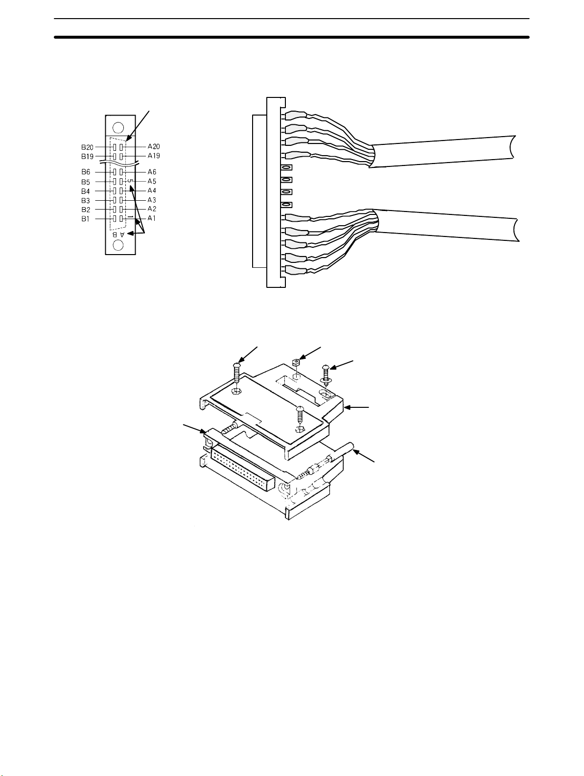
Differentiating Cables and
Connector Pin Numbers
Input and output cables can be differentiated by position, as shown on the
right below. Alignment with the connector pin numbers is also as shown on
the left below. Please make sure you are wiring to the correct pins.
Shape of connector
on the reverse side.
Pin number
marks
Connector pins as viewed
from the solder side.
Assembling Connectors Assemble connectors as shown below.
Round head screw
(8mm M2, two total)
Nut (M2, four total)
Input cables
Output cables
Round head screw
(10mm M2, two total)
Case
Connector
Lock screw
Note Any of the following connectors can be used as required by operating condi-
tions. The jack is a Fujitsu model 360.
1, 2, 3... 1. FCN-361J040 (solder-type, included with Counter Unit)
FCN-360C040-B (connector cover)
2. FCN-363J040 (crimp type, housing)
FCN-363J-AU (connector)
FCN-360C040 (connector cover)
3. FCN-367J040-A V/F (crimp type)
Wiring Precautions For the C200H-CT001-V1, the terminals that are used depend upon the pow-
er supply of inputs A, B, and Z.
For the C200H-CT002, inputs A, B, and Z must be line driver inputs
(Am26LS31-compatible). Positive and negative terminals must be wired correctly. The terminals that are used depend upon the power supply of the control
inputs. Be careful to connect to the correct terminals. Supply only one voltage for
12
Page 27
Wiring Section 2-2
each input. The terminals for output power supply , 5 t o 2 4 VDC and COM (0 V),
are separated into two: those for outputs 0 through 7. These are not interconnected internally. If the 5 to 24 VDC and COM (0 V) terminals for the output power supply are connected incorrectly, an internal fuse will burn out, preventing operation. This fuse is not user serviceable. This fuse will also burn out if the output
current exceeds 0.5 A/common, again preventing operation. When wiring inputs
A, B, and Z, the following measures must be taken to prevent interference from
noise:
1, 2, 3... 1. Use shielded twisted pair cable and ground the shield.
2. Keep wiring as short as possible and do not place lines parallel to pos-
sible sources of noise, such as power lines.
3. Use a stabilized power supply that is independent from other input and
output power supplies.
The external power supply must be greater than or equal to the load power supply. (An error may occur if the external power supply is less than the load power
supply .) I n the example on the following page, E1 must be greater than or equal
to E2.
5 to 24 VDC
Output 0
D
r
i
v
e
c
i
rc
u
i
t
Output 1
Output 2
Output 3
Fuse COM
0.5A (0 V)
B8
A8
A7
A6
A5
B6
Counter Unit
Relay
Relay
Relay
Relay
Variable
resistors
E1
0 V
E2
0 V
~
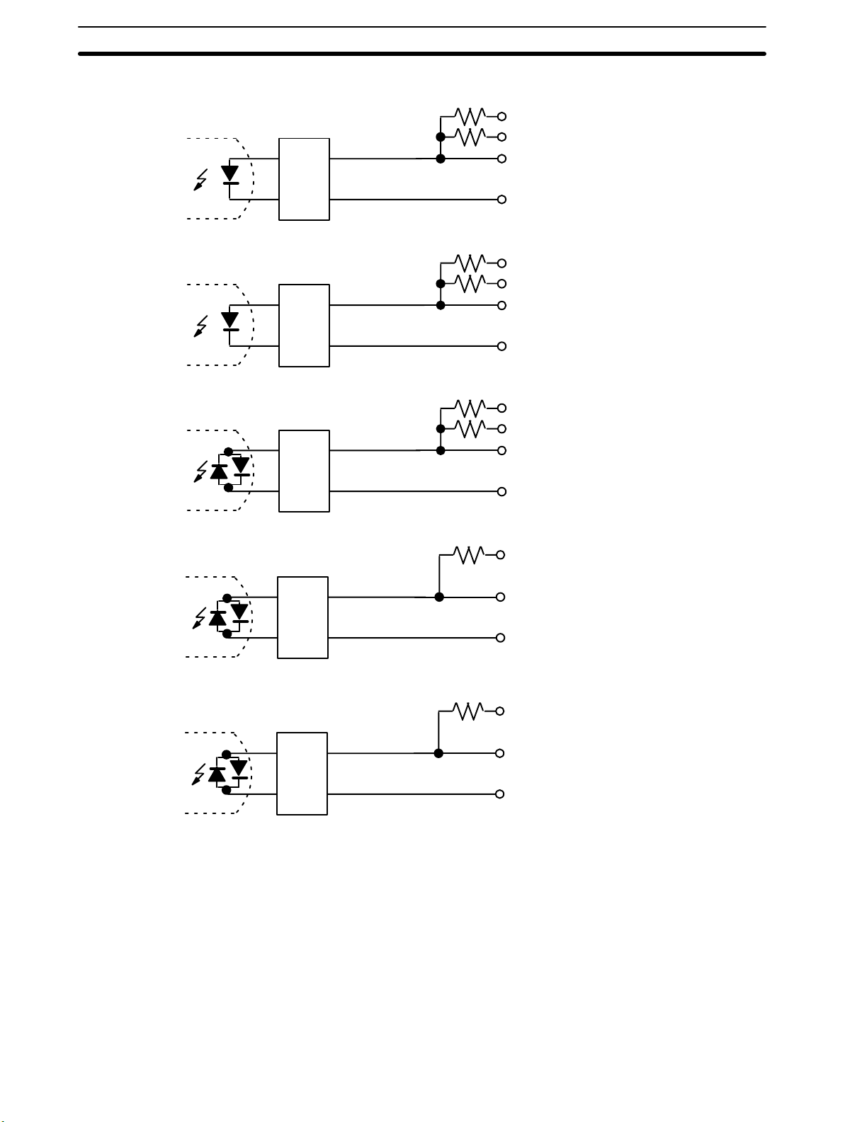
Input and Output Circuits Actual pin numbers are arranged in order from the top of the connector start-
ing with A20 and B20. For each input, connect the 0-V terminal and only one
of the other terminals, i.e., do not supply more than one voltage for any input.
The circuits are shown on the following pages.
13
Page 28
Wiring Section 2-2
C200H-CT001-V1 Input Circuits
1.6 kΩ
B20...... Input A: 24 VDC
560 Ω
A20...... Input A: 12 VDC
A19...... Input A: 5 VDC
Rectifier
B19...... Input A: 0 V
1.6 kΩ
B18...... Input B: 24 VDC
560 Ω
A18...... Input B: 12 VDC
A17...... Input B: 5 VDC
Rectifier
B17...... Input B: 0 V
1.6 kΩ
B16...... Input Z: 24 VDC
560 Ω
A16...... Input Z: 12 VDC
A15...... Input Z: 5 VDC
Rectifier
B15...... Input Z: 0 V
Filter
Filter
1.3 kΩ
1.3 kΩ
A13......
A12......
B12......
A11......
A10......
B10......
Control input
IN1: 12/24 VDC
Control input
IN1: 5 VDC
Control input
IN1: 0 V
Control input
IN1: 12/24 VDC
Control input
IN1: 5 VDC
Control input
IN1: 0 V
14
Page 29

Wiring Section 2-2
C200H-CT001-V1 Output Circuits
B8......Output power
supply: 5 to 24 VDC
A8......Output 0
A7......Output 1
A6......Output 2
Fuse
0.5 A
~
Fuse
0.5 A
~
A5......Output 3
B6......Output COM: 0 V
B4......Output power
supply: 5 to 24 VDC
A4......Output 4
A3......Output 5
A2......Output 6
A1......Output 7
B2......Output COM: 0 V
15
Page 30
Wiring Section 2-2
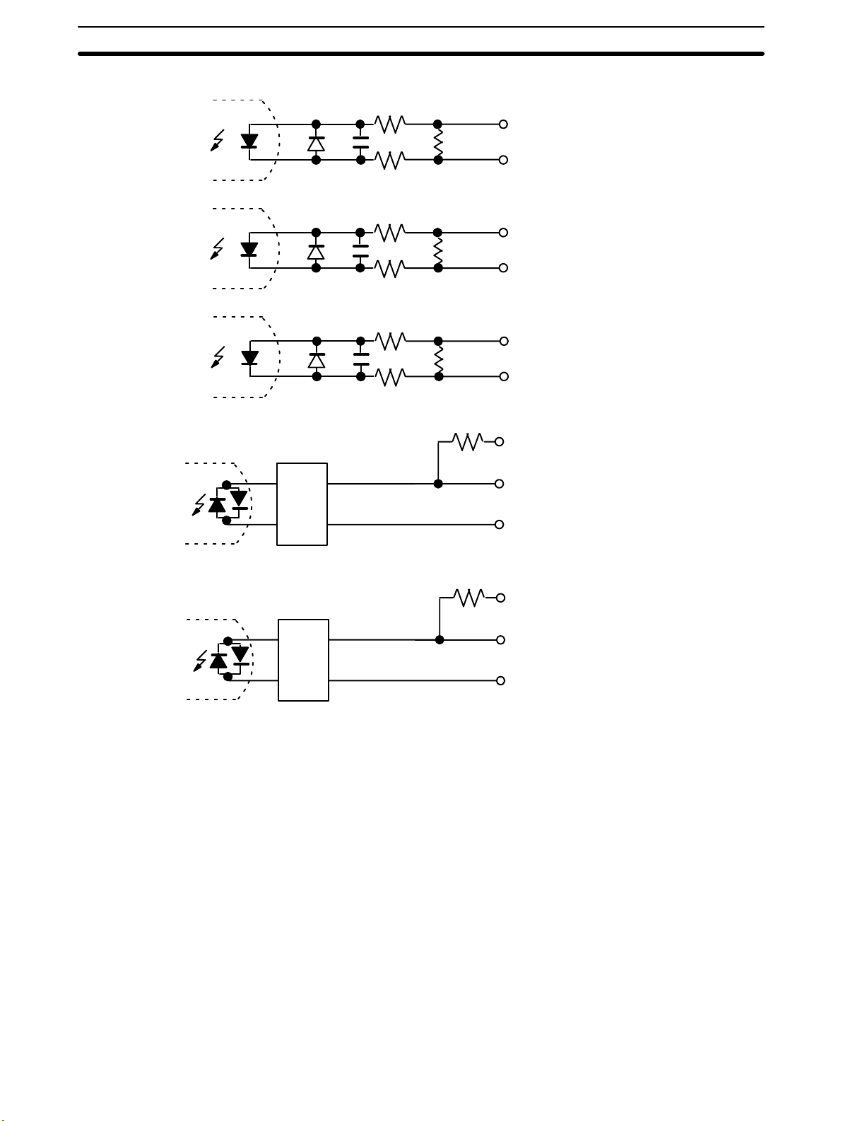
C200H-CT002 Input Circuits
A19...... Input A: pos.
B19...... Input A: neg.
A17...... Input B: pos.
B17...... Input B: neg.
A15...... Input Z: pos.
B15...... Input Z: neg.
Filter
Filter
1.3 kΩ
1.3 kΩ
A13......
A12......
B15......
A11......
A10......
B10......
Control input
IN1: 12/24 VDC
Control input
IN1: 5 VDC
Control input
IN1: 0 V
Control input
IN1: 12/24 VDC
Control input
IN1: 5 VDC
Control input
IN1: 0 V
16
Page 31

Wiring Section 2-2
C200H-CT002 Output Circuits
B8......Output power
supply: 5 to 24 VDC
A8......Output 0
A7......Output 1
A6......Output 2
Fuse
0.5 A
~
Fuse
0.5A
~
A5......Output 3
B6......Output COM: 0 V
B4......Output power
supply: 5 to 24 VDC
A4......Output 4
A3......Output 5
A2......Output 6
A1......Output 7
B2......Output COM: 0V
17
Page 32

Input Circuit Wiring Examples Section 2-3
2-3 Input Circuit Wiring Examples
2-3-1 C200H-CT001-V1
Examples The following wiring examples show connections between encoders and in-
puts A, B, and Z.
Example 1
12-VDC, Open-collector
Encoder
C200H-CT001-V1 Counter Unit
Input A
Rectifier
Input B
Rectifier
This example shows the connections that would be used for a 12-VDC power
supply and an incremental encoder with a open-collector output.
+
12-VDC
power
supply
24 V
12 V
5 V
0 V
24 V
12 V
5 V
0 V
Shielded twisted pair cable
A IA
I
IB IB
12 VDC
0 V
Power supply
–
Encoder
Input Z
Filter
24 V
12 V
5 V
IZ IZ
0 V
E
18
Page 33

Input Circuit Wiring Examples Section 2-3
Example 2
12-VDC, Voltage-output,
Sync-load Encoder
C200H-CT001-V1 Counter Unit
Input A
Rectifier
Input B
Rectifier
This example shows the connections that would be used for a 12-VDC power
supply and a sync-load encoder with a voltage output. When the encoder
output is high, the input to the Counter Unit turns OFF. When the encoder
output is low, the input to the Counter Unit turns ON.
+
12-VDC
power
supply
24 V
12 V
5 V
0 V
24 V
12 V
5 V
0 V
Shielded twisted pair cable
A IA
I
IB IB
12 VDC
0 V
Power supply
–
Encoder
Input Z
Filter
24 V
12 V
5 V
IZ IZ
0 V
E
19
Page 34

Input Circuit Wiring Examples Section 2-3
Example 3
5 VDC, Voltage-output,
Source-load Encoder
CT001-V1 Counter Unit
Input A
Rectifier
Input B
Rectifier
This example shows the connections that would be used for a 5-VDC power
supply and a source-load encoder with a voltage output. Here, attention must
be paid to the ON voltage.
+
5 VDC
0 V
–
Encoder
24 V
12 V
5 V
0 V
24 V
12 V
5 V
0 V
5-VDC
power
supply
Shielded twisted pair cable
A
I
IB
Input Z
Filter
24 V
12 V
5 V
IZ
0 V
E
20
Page 35

Input Circuit Wiring Examples Section 2-3
2-3-2 C200H-CT002
Example 1
Line-driver Encoder
C200H-CT002 Counter Unit
Input A
Input B
Input Z
The following wiring examples shows connections between a line-driver encoder (Am26LS31-compatible) with outputs A, B, Z and inputs A, B, and Z.
Power supply
Encoder
Shielded twisted pair cable
+
–
+
–
+
–
E
A+
A–
B+
B–
C+
C–
Example 2
Open-collector Encoder
and Encoder Adapter
C200H-CT002 Counter Unit
Input A
Input B
Input Z
The following wiring example shows connections between an open-collector
encoder and an Encoder Adapter (C500-AE001), and between the Encoder
Adapter and inputs A, B, and Z. Connections should be wired so that Counter
Unit inputs go ON when encoder outputs go ON. Because the C500-AE001
Encoder Adapter uses an Am26LS31-compatible line driver, high voltage is
impressed on the positive terminal and low voltage is impressed on the negative terminal when the output is high.
Shielded twisted pair cable
+
–
+
–
+
–
5- to
12-VDC
power
supply
+
–
C500-AE001 Encoder Adapter
A–
A+
B–
B+
Z–
Z+
E
V
CC
0 V
Voltage
regulator
Shielded
twisted
pair cable
CC
V
0 V
Encoder
E
CC
V
0 V
21
Page 36

Input Circuit Wiring Examples Section 2-3
Control Input Wiring
Examples
Counter Unit
Control input IN1
Filter
Filter
In order to prevent chattering, install the input wiring with as few contacts as
possible.
+
0 V
–
Sensor
Sensor
output
Sensor
Sensor
output
12/24 V
5 V
0 V
12/24 V
5 V
0 V
12- to
24-VDC
power
supply
Twisted pair cable
12 to 24 VDC
22
Page 37

Input Circuit Wiring Examples Section 2-3
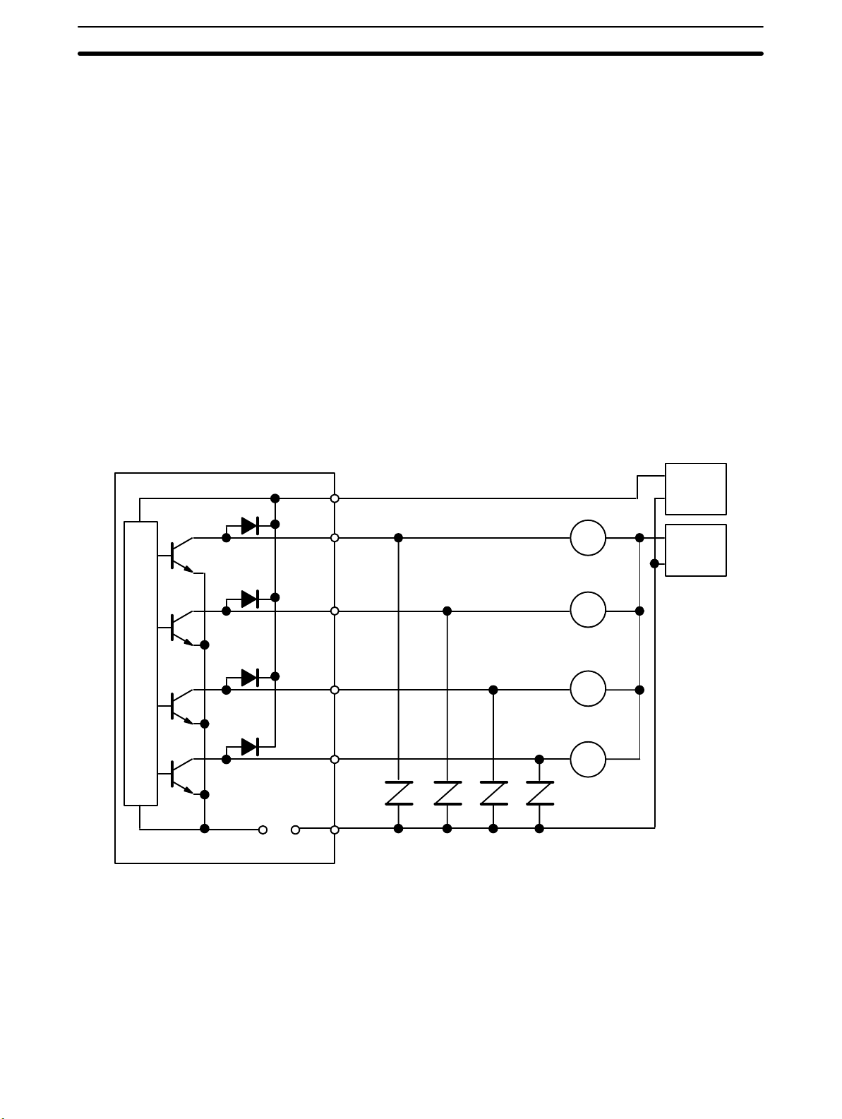
External Output Wiring
Example
Drive circuitDrive circuit
5 to 24 VDC
Output 0
Output 1
Output 2
Output 3
The following example shows output wiring with outputs 0 through 3 connected to relays and outputs 4 through 7 connected to TTL devices.
A8
A8
A7
A6
A5
Counter Unit
Relay
Relay
Relay
Relay
+
5 to 24 VDC
5- to
24-VDC
0 V
power
supply
–
Switching capacity
depends upon the
voltage. Refer to Appendix B Specifications.
Fuse COM
0.5 A (0 V)
~
5 to 24 VDC
Output 4
Output 5
Output 6
Output 7
Fuse COM
0.5 A (0 V)
~
B6
B4
A4
A3
A2
A1
B2
Counter Unit
Pull-up resistors
(4.7 k
Ω)
Variable
resistors
–
5 VDC
0 V
Output 4
Output 5
Output 6
Output 7
Low
High
+
Buffers
Output Voltages for Outputs 0 through 7
Output ON.
Output OFF.
5 VDC
23
Page 38

Dimensions Section 2-4
2-4 Dimensions
Unit Dimensions (Unit: mm)
130
Mounted Dimensions (Unit: mm)
Connecting
cable
35
100.5
Rack
117
Approx. 200
24
Page 39

SECTION 3
Operation
This section describes the operational flow of the counting system. The input types are identified along with instructions
for their use. Data transfer timing is described in relation to the PC cycle time.
3-1 Operational Flow 26. . . . . . . . . . . . . . . . . . . . . . . . . . . . . . . . . . . . . . . . . . . . . . . . . . . . . . . . .
3-2 Input Selection 26. . . . . . . . . . . . . . . . . . . . . . . . . . . . . . . . . . . . . . . . . . . . . . . . . . . . . . . . . . .
3-2-1 Offset Phases 26. . . . . . . . . . . . . . . . . . . . . . . . . . . . . . . . . . . . . . . . . . . . . . . . . . . . .
3-2-2 Up and Down Pulses 28. . . . . . . . . . . . . . . . . . . . . . . . . . . . . . . . . . . . . . . . . . . . . . .
3-2-3 Pulse and Direction 28. . . . . . . . . . . . . . . . . . . . . . . . . . . . . . . . . . . . . . . . . . . . . . . .
3-3 Counter Reset Conditions 29. . . . . . . . . . . . . . . . . . . . . . . . . . . . . . . . . . . . . . . . . . . . . . . . . . .
3-4 Data Transfer Timing 30. . . . . . . . . . . . . . . . . . . . . . . . . . . . . . . . . . . . . . . . . . . . . . . . . . . . . .
25
Page 40

Input Selection Section 3-2
3-1 Operational Flow
Each Special I/O Unit mounted under a C200H PC is assigned a unit number
between 0 and 9. The unit number assigned to the Counter Unit determines the
100 DM words and 10 IR words that will be allocated to it. DM words are used for
Counter Unit parameters; IR words, for command bits and flags. (Refer to 4-1
Data Configuration and Allocation for details.) The following procedure outlines
the steps necessary to operate the Counter Unit.
1, 2, 3... 1. Set the mode selector on the front panel to the desired operating mode,
and then set the DIP switch on the rear panel accordingly. (Refer to 2-1
Switch Settings.)
2. Set the unit number with the selector on the front panel. (Refer to 2-1
Switch Settings.)
3. Using the Programming Console, set data required in the DM area under the unit number.
4. Prepare the user program to operate the Counter Unit using the allocated IR area words and bits.
It is also possible to set parameters and counter values in any data area using
the user program or the Programming Console. This data can then be transferred to the Counter Unit by using the TRANSFER DATA command bit. (Refer
to page 40 TRANSFER DATA Command.)
3-2 Input Selection
Any one of three types of inputs can be selected: offset phase inputs (i.e., two
inputs with offset phases), individual up and down inputs, and pulse and direction inputs. All three types of inputs include a reset input. Any type of any input
can be used with any of the operating modes, although not all operating modes
support resetting. (Refer to Section 4 Data allocation and Operating Modes for
details.) The type of inputs is selected with the back panel DIP switch.
3-2-1 Offset Phases
Offset phase inputs use the difference in phase between two inputs to determine
whether the counter value will be incremented or decremented. An input multiplier, either x 2 or x 4, is available with offset phase inputs to increase accuracy. I f
the x 2 multiplier is selected, the counter value will be incremented or decremented twice for each input A pulse; if the x 4 multiplier is selected, the counter
value will be incremented or decremented four times for each input A pulse. The
multiplier is set with the back panel DIP switch. (Refer to 2-1 Switch Settings.)
The counter can be reset in the linear or circular operating modes by using the
Z-phase output of the encoder. Refer to 3-3 Reset Conditions for details.
Encoder
Phase A
Phase B
Wire according
to the counting
direction
Counter Unit
Input A
Input B
Phase Z (reset input)
Counting Speed The maximum pulse frequency possible for offset phase inputs is determined
by the specifications of the incremental encoder connected to the Counter
Input Z
26
Page 41

Input Selection Section 3-2
Units. The following example shows calculations E6B-CWZ3C Incremental
Encoder when used with the C200H-CT001-V1. Rotational directions are given as viewed from the end of the encoder shaft.
Encoder Specifications
Power supply 4.75 to 13.2 VDC, ripple (p-p): 5% max.
Current consumption 50 mA max.
Resolution 500 pulses/revolution
Outputs Phase A, phase B, phase Z
Output type Open collector
Output capacity Applied voltage: 30 VDC max.
Sync. current: 80 mA max.
Residual voltage: 1 V max
Max. frequency 30 kHz
Output phase difference
(between phase A and B)
Output fall/rise time
90°±45° (1/4T±1/8T)
1.0 µs max.
CW Rotation Here, input A is advanced by 1/4T±1/8T over input B.
Towards CW
Input A
Input B
ON
OFF
ON
OFF
T
°)
(360
1/4 T±1/8 T (90°±45°)
CCW Rotation Here, input A is delayed by 1/4T±1/8T over input B.
Towards CCW
Input A
Input B
ON
OFF
ON
OFF
T
°)
(360
1/4 T + 1/8 T (90°+ 45°)
Since the output phase difference is 90°±45°, the minimum phase difference
produced by this encoder is as follows:
90° – 45° = 45°
Because the C200H-CT001-V1 requires a minimum phase difference of 4.5 4.5
must be less than 45°/360°. T must therefore be less than 36 meaning the maximum frequency, 1/T, would be 27.7 kcps (54 rps for 500 pulses per revolution).
This would be the maximum frequency at which this encoder could be used with
the C200H-CT001-V1. With the C200H-CT002, a minimum phase difference of
3 is required. Computing as above shows a maximum frequency of 41.7 kcps
when using the C200H-CT002 with this encoder.
Note The minimum pulse width must be considered when using input Z to reset
the counter. With the C200H-CT001-V1, the pulse width of input Z must be
0.1 ms or greater, and the return frequency must be 5 kcps or less. With the
27
Page 42

Input Selection Section 3-2
C200H-CT002, the pulse width of input Z must be 10 or greater, and the return frequency, allowing for software processing time, must be 10 kcps or
less.
3-2-2 Up and Down Pulses
With separate up and down pulse inputs, the counter value is incremented or
decremented on the rising edge of the appropriate input. Here, sensors could
replace the encoders to provide inputs A and B.
In the linear or circular operating modes, the counter can be reset by connecting
input Z to a sensor or switch.
Encoder or sensor
Encoder or sensor
Sensor or switch
3-2-3 Pulse and Direction
With pulse and direction inputs, the counter value is incremented or decremented on the rising edge of the pulse input. If the direction input is OFF, the
counter value is incremented; if the direction input is ON, the counter value is
decremented. The direction input should be switched between ON and OFF
only when the pulse input is OFF.
Counter Unit
Increment pulse
Input A
Decrement pulse
Input B
Reset input
Input Z
28
In the linear or circular operating modes, the counter can be reset by connecting
input Z to a sensor or switch.
Encoder or sensor
Sensor or switch
Counter Unit
Pulse Input
Input A
Direction input
Input B
Reset input
Input Z
Page 43

Counter Reset Conditions Section 3-3
3-3 Counter Reset Conditions
Counter reset conditions vary according to the combination of inputs used and
pin settings on the back panel DIP switch. The DIP switch settings required for
the input combinations shown in the following table and the operating modes
that can be used with each are shown on the next page. (The numbers 1 through
17 above the input patterns correspond to the settings.) Resetting is not possible
in the gate, latch, and sampling operating modes. All inputs for each pattern
must be in the status shown for setting to be ef fective. The minimum input pulse
width for the input Z is 0.1 ms;that for the control input IN1, 1 ms.
In the following table, input Z is indicated by Z; control input IN1, by IN1, and the
internal reset bit, by IRB. The point at which the reset actually takes place is indicated by the arrow at the bottom of each pattern. The DIP switch settings for
each pattern are described on the following page.
Inputs used Reset conditions and timings
1 2 3 4
Input Z
Control input IN1
Internal reset bit
Input Z
Control input IN1
Z
IN1
IRB
5 6 7 8
Z
IN1
Z
IN1
IRB
Z
IN1
Z
IN1
IRB
Z
IN1
Z
IN1
IRB
Z
IN1
Input Z
Internal reset bit
Control input IN1
Internal reset bit
Input Z
Control input IN1
Internal reset bit
9 10
Z
IRB
11 12
IN1
IRB
13 14
Z Z
15 16
IN1 IN1
17
IRB
Z
IRB
IN1
IRB
29
Page 44

Data Transfer Timing Section 3-4
DIP Switch Settings Pins 1 through 3 do not affect resetting
Pattern number on
previous page
1 ON ON ON ON ON OK OK OK
2 ON ON ON OFF ON OK OK OK
3 ON OFF ON ON ON OK OK OK
4 ON OFF ON OFF ON OK OK OK
5 ON ON ON ON OFF OK OK OK
6 ON ON ON OFF OFF OK OK OK
7 ON OFF ON ON OFF OK OK OK
8 ON OFF ON OFF OFF OK OK OK
9 ON ON OFF * ON OK OK OK
10 ON OFF OFF * ON OK OK OK
11 OFF * ON ON ON OK OK OK
12 OFF * ON OFF ON OK OK OK
13 ON ON OFF * OFF OK OK OK
14 ON OFF OFF * OFF OK OK OK
15 OFF * ON ON OFF OK OK OK
16 OFF * ON OFF OFF OK OK OK
17 OFF * OFF * ON OK OK OK
Pin Settings Possible operating modes
4 5 6 7 8 Linear Circular Preset
*These pins may be either ON or OFF.
3-4 Data Transfer Timing
Data transfer is available in linear and circular modes to change ranges limit settings or the current counter value and in preset mode to change range limit settings. The data to be transferred must be prepared in the appropriate form in a
PC data area. Data transfer specifications and procedures are described under
the relevant operating modes. This section describes only data transfer timing in
relation to the PC cycle time.
C200H Cycle Time The C200H PC cycle consists of the following operations.
Cycle time Cycle time
Common
processing
Host
link
servicing
Peripheral device
servicing
Processing
I/O refresh
cycle
Common
processing
Host
link
servicing
Peripheral device
servicing
Processing
I/O refresh
cycle
30
Page 45
Data Transfer Timing Section 3-4
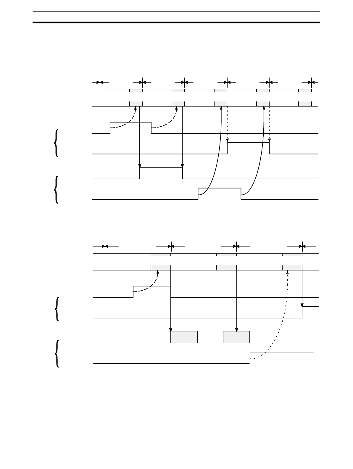
Data Transfer Input and output data is transferred during the I/O refresh cycle. This means
that PC acknowledgement of inputs from the Counter Unit (e.g., status) and
Counter Unit acknowledgement of outputs from the PC (e.g., commands) are
delayed until the next I/O refresh cycle, as shown below.
Cycle time Cycle time Cycle time Cycle time Cycle time
C200H
Counter
Unit
START and other outputs
Counting flag
and other inputs
START and other outputs
Counting flag
and other inputs
I/O
refresh cycle
I/O
refresh cycle
I/O
refresh cycle
I/O
refresh cycle
Data transfer would enter into the cycle time as shown below:
Cycle time Cycle time Cycle time
I/O
refresh cycle
I/O
refresh cycle
I/O
refresh cycle
I/O
refresh cycle
Data transfer
C200H
Transfer completed flag
Internal processing
Counter
Unit
Transfer completed flag
Data Transfer in Remote I/O
Systems
Data transfer acknowledged. Data transfer executed.
Note: The transfer completed flag reverses status (ON to OFF
or OFF to ON) each time a transfer is completed.
When the Counter Unit is mounted on a Rack containing a Remote I/O Slave
Unit, a delay will occur due to data transfer between the Remote I/O Master
Unit and the Remote I/O Slave Unit. See the C200H Programming Manual
for details.
31
Page 46

Page 47

SECTION 4
Data Allocation and Operating Modes
This section describes the various operating modes in detail. Each mode is described by data allocation, timing charts,
commands, flags, and examples. Data formats are explained.
4-1 Data Configuration and Allocation 34. . . . . . . . . . . . . . . . . . . . . . . . . . . . . . . . . . . . . . . . . . .
4-2-1 Data Allocation 36. . . . . . . . . . . . . . . . . . . . . . . . . . . . . . . . . . . . . . . . . . . . . . . . . . .
4-2-2 DM Area Settings 39. . . . . . . . . . . . . . . . . . . . . . . . . . . . . . . . . . . . . . . . . . . . . . . . .
4-2-3 IR Area Settings 40. . . . . . . . . . . . . . . . . . . . . . . . . . . . . . . . . . . . . . . . . . . . . . . . . . .
4-2-4 Timing Chart 46. . . . . . . . . . . . . . . . . . . . . . . . . . . . . . . . . . . . . . . . . . . . . . . . . . . . .
4-2-5 Application Examples 47. . . . . . . . . . . . . . . . . . . . . . . . . . . . . . . . . . . . . . . . . . . . . .
4-3 Preset Mode 52. . . . . . . . . . . . . . . . . . . . . . . . . . . . . . . . . . . . . . . . . . . . . . . . . . . . . . . . . . . . .
4-3-1 Data Allocation 52. . . . . . . . . . . . . . . . . . . . . . . . . . . . . . . . . . . . . . . . . . . . . . . . . . .
4-3-2 DM Area Settings 55. . . . . . . . . . . . . . . . . . . . . . . . . . . . . . . . . . . . . . . . . . . . . . . . .
4-3-3 IR Area Settings 56. . . . . . . . . . . . . . . . . . . . . . . . . . . . . . . . . . . . . . . . . . . . . . . . . . .
4-3-4 Timing Chart 60. . . . . . . . . . . . . . . . . . . . . . . . . . . . . . . . . . . . . . . . . . . . . . . . . . . . .
4-3-5 Application Example 61. . . . . . . . . . . . . . . . . . . . . . . . . . . . . . . . . . . . . . . . . . . . . . .
4-4 Gate, Latch, and Sampling Modes 63. . . . . . . . . . . . . . . . . . . . . . . . . . . . . . . . . . . . . . . . . . . .
4-4-1 Data Allocation 64. . . . . . . . . . . . . . . . . . . . . . . . . . . . . . . . . . . . . . . . . . . . . . . . . . .
4-4-2 DM Area Settings 65. . . . . . . . . . . . . . . . . . . . . . . . . . . . . . . . . . . . . . . . . . . . . . . . .
4-4-3 IR Area Settings 65. . . . . . . . . . . . . . . . . . . . . . . . . . . . . . . . . . . . . . . . . . . . . . . . . . .
4-4-4 Timing Charts 66. . . . . . . . . . . . . . . . . . . . . . . . . . . . . . . . . . . . . . . . . . . . . . . . . . . .
4-4-5 Application Examples 70. . . . . . . . . . . . . . . . . . . . . . . . . . . . . . . . . . . . . . . . . . . . . .
33
Page 48

Data Configuration and Allocation Section 4-1
4-1 Data Configuration and Allocation
IR words 100 through 199 are allocated as I/O refresh areas. Each Counter Unit
is allocated 10 consecutive words (although not all modes use all 10 words). The
first IR word for each Counter Unit, designated in this manual as n, can be computed from the unit numbers as follows:
n = 100 + 10 x unit number.
IR words are refreshed during the PC’s I/O refresh cycle. Note that input and out-
put designations are in reference to the PC, e.g., command bits are outputs, status bits are inputs.
Each Counter Unit is also allocated 100 consecutive words as a parameter area
(although not all modes use all 100 words). These words are in the DM area and
run from DM 1000 through DM 1999. The first DM word for each Counter Unit, m,
can also be computed from the unit number:
m = 1000 + 100 x unit number.
All DM area data for the Counter Unit is transferred to it whenever power is
turned ON or the Counter Unit is reset.
34
Page 49

Data Configuration and Allocation Section 4-1
These allocations are shown below for all unit numbers. Details of allocations
within these words are given under the operating modes to which they apply. A
quick overview of word and bit allocations is available in Appendix C IR Area Al-
locations and Appendix D DM Area Coding Sheets.
C200H PC Counter Unit
DM area
Unit #0
DM 1000 through 1099
DM 1100 through 1199Unit #1
DM 1200 through 1299Unit #2
DM 1300 through 1399Unit #3
DM 1400 through 1499Unit #4
DM 1500 through 1599Unit #5
DM 1600 through 1699Unit #6
DM 1700 through 1799Unit #7
DM 1800 through 1899Unit #8
DM 1900 through 1999Unit #9
Data is automatically transferred to the
Counter Unit when
power is turned or
when its restart flag
in the AR area is
turned ON.
Parameter area
Word m
∫
Word m+99
Data is transferred to the Counter Unit
when the TRANSFER DATA command
bit of the IR area si turned ON after setting the TRANSFER DATA command to
the specified data area.
Specified Data Area
(DM, fixed DM, I/O, LR, HR, or AR)
IR area
Data transfer
Data is transferred
when TRANSFER
DATA is set.
100 through 109Unit #0
110 through 119Unit #1
120 through 129Unit #2
130 through 139Unit #3
140 through 149Unit #4
150 through 159Unit #5
160 through 169Unit #6
170 through 179Unit #7
180 through 189Unit #8
190 through 199Unit #9
Data is transferred to the
Counter Unit each
I/O refresh.
Word n to n+4
Word n+4 to n+9
I/O Area
Output data area
Input data area
35
Page 50

Linear and Circular Modes Section 4-2
Data Format Data is allocated by either bit or by word, though it is often input and output
by decimal digit, i.e., four bits (BCD), or by hexadecimal digit. Counter values, upper and lower limits of ranges, and some other data are held in two
adjacent words, sometimes with a sign digit, in the following format.
Highest word Lowest word
sign x 106x 105x 104x 103x 102x 101x 10
0
1
+
–
Note that the rightmost word is always the lowest word, i.e., if the two words were
m+10 and m+11, the rightmost word would be m+10; the leftmost, m+11. Furthermore, the rightmost digit in each word begins in the lowest bits, i.e., the digits
4
and x 100 above would be held in, bits 00 through 03 of their respective
x 10
words. Even when only one word or part of a word is required to hold data, e.g.,
the error code or error location, the rightmost digit is also always held in the lower
bits. Although decimal notation is generally used for data in this manual, data is
handled in the system as binary-coded decimal (BCD) unless otherwise noted.
Note that this data is generally input as decimal, whereas hexadecimal data is
input as hexadecimal. The number of digits given for certain data refers to the
decimal digits, e.g., “7 digits with sign” indicates that the lowest word and right-
most 12 bits of the highest word are allocated to the 7-digit decimal value; the
leftmost four bits are allocated to the sign digit.
4-2 Linear and Circular Modes
In both linear and circular modes counter values are incremented and decremented according to any of the three types of input pulses. All functional aspect
and data allocations for these two modes are the same, except that in linear
mode, counter values range linearly between –8,388,608 and 8,388,607, while
in circular mode, counter values range from 0 to a preset maximum value (used
only in circular mode), with the maximum value and 0 being adjacent to each
other in sequence. That is, decrementing below 0 results in the current counter
value going to the maximum value; incrementing past the maximum value results in the current counter value going to zero.
Both modes provide 16 outputs, all of which can be output internally (i.e., to the
PC) and eight of which can be output externally (i.e., without passing through the
PC) as well as internally. These outputs are sometimes referred to by number
and sometimes as either internal inputs and external inputs. The term internal
outputs refers to all outputs sent to the PC; external outputs, to all outputs set to
the external connector.
Both modes provide 16 ranges for counter values during which the outputs can
be set to turn ON. These ranges can be enabled or disabled during operations.
Data transfer from the PC data area is also available in both modes to change
either range settings or the current counter value.
Although control input IN1 is supposed by both modes, control input IN2 is not
used.
Note Stop counter operation before changing the present value to 0 or resetting
the Counter Unit in the ring mode. If either of these is performed without
stopping counter operation, the maximum value preset operation will not be
performed correctly.
0
4-2-1 Data Allocation
The commands, parameters, flags, and other information in the following tables
are described in detail in 4-2-2 DM Area Settings and 4-2-3 IR Area Settings.
36
Page 51

Linear and Circular Modes Section 4-2
DM Area The DM area contains user parameters that are to be set into the Counter
Unit, including the operating mode and output range limits. The first DM word
for each Counter Unit is indicated by m and equals 1,000 plus 100 times the
unit number.
Word Bit Function
m 07 through 00 Set to 0.
11 through 08 Operating mode (Here, either 1: linear or 2: circular)
15 through 12 Set to 0.
m + 1 15 through 00 Effective range bits (bit numbers correspond to range numbers)
m + 2
m + 3 15 through 00 6 digits (Bits 15 to 04 not used.)
m + 4
m + 9
m + 10 15 through 00 Lower limit for range #0, 7 digits with sign digit
m + 11 15 through 00
m + 12 15 through 00 Upper limit for range #0, 7 digits with sign digit
m + 13 15 through 00
m + 14 15 through 00 Output pattern for range #0 (bit numbers correspond to output numbers)
m + 15
m + 19
m + 20
m + 24
m + 25
m + 29
m + 30
m + 34
m + 35
m + 39
m + 40
m + 44
m + 45
m + 49
m + 50
m + 54
m + 55
m + 59
m + 60
m + 64
m + 65
m + 69
m + 70
m + 74
m + 75
m + 79
m + 80
m + 84
m + 85
m + 89
m + 89
m + 99
15 through 00 Maximum counter value (for circular mode only)
Not used.
Lower limit, upper limit, and output pattern for range #1 (Format same as
that for range #0.)
Lower limit, upper limit, and output pattern for range #2 (Format same as
that for range #0.)
Lower limit, upper limit, and output pattern for range #3 (Format same as
that for range #0.)
Lower limit, upper limit, and output pattern for range #4 (Format same as
that for range #0.)
Lower limit, upper limit, and output pattern for range #5 (Format same as
that for range #0.)
Lower limit, upper limit, and output pattern for range #6 (Format same as
that for range #0.)
Lower limit, upper limit, and output pattern for range #7 (Format same as
that for range #0.)
Lower limit, upper limit, and output pattern for range #8 (Format same as
that for range #0.)
Lower limit, upper limit, and output pattern for range #9 (Format same as
that for range #0.)
Lower limit, upper limit, and output pattern for range #10 (Format same as
that for range #0.)
Lower limit, upper limit, and output pattern for range #11 (Format same as
that for range #0.)
Lower limit, upper limit, and output pattern for range #12 (Format same as
that for range #0.)
Lower limit, upper limit, and output pattern for range #13 (Format same as
that for range #0.)
Lower limit, upper limit, and output pattern for range #14 (Format same as
that for range #0.)
Lower limit, upper limit, and output pattern for range #15 (Format same as
that for range #0.)
Not used.
37
Page 52

Linear and Circular Modes Section 4-2
IR Area The IR area contains commands and status information. Inputs and outputs
are given in reference to the PC, i.e., output data is sent from the PC to the
Counter Unit; input data, from the Counter Unit to the PC. The first IR word
for each Counter Unit is indicated by n and equals 100 plus 10 times the unit
number.
Outputs
Word Bit Function
00
START command
01
TRANSFER DATA command
02
ENABLE OUTPUT command
03
Not used.
04
CHANGE RANGES command
05
READ ERROR command
06
RESET COUNTER command
07
n
n+1
n+2
n+3
ENABLE FORCED OUTPUT command
08
Output #0 force bit
09
Output #1 force bit
10
Output #2 force bit
11
Output #3 force bit
12
Output #4 force bit
13
Output #5 force bit
14
Output #6 force bit
15
Output #7 force bit
00
Range #0 enable bit
01
Range #1 enable bit
02
Range #2 enable bit
03
Range #3 enable bit
04
Range #4 enable bit
05
Range #5 enable bit
06
Range #6 enable bit
07
Range #7 enable bit
08
Range #8 enable bit
09
Range #9 enable bit
10
Range #10 enable bit
11
Range #11 enable bit
12
Range #12 enable bit
13
Range #13 enable bit
14
Range #14 enable bit
15
Range #15 enable bit
TRANSFER DATA beginning word
15
−00
number, 4 digits
TRANSFER DATA data area, 0 to 4
03−00
Not used. (Set to 0.)
07
−04
Number of transfers, 1 to 3
15
−08
Inputs
Word Bit Function
Counting flag
00
Z flag
01
IN1 flag
02
IN2 flag
03
n+4
n+5
n+6
n+7
n+8
n+9
Transfer completed flag
04
Error flag
05
Count overflow flag
06
Reset flag
07
Not used
08
Error location
07−00
Error code
15
−08
Current counter value, 7 digits with sign
−00
15
(–8,388,608 to +8,388,607)
15
−00
Range #0 flag
00
Range #1 flag
01
Range #2 flag
02
Range #3 flag
03
Range #4 flag
04
Range #5 flag
05
Range #6 flag
06
Range #7 flag
07
Range #8 flag
08
Range #9 flag
09
Range #10 flag
10
Range #11 flag
11
Range #12 flag
12
Range #13 flag
13
Range #14 flag
14
Range #15 flag
15
Output #0 flag (external output possible)
00
Output #1 flag (external output possible)
01
Output #2 flag (external output possible)
02
Output #3 flag (external output possible)
03
Output #4 flag (external output possible)
04
Output #5 flag (external output possible)
05
Output #6 flag (external output possible)
06
Output #7 flag (external output possible)
07
Output #8 flag (internal output only)
08
09
Output #9 flag (internal output only)
10
Output #10 flag (internal output only)
11
Output #11 flag (internal output only)
12
Output #12 flag (internal output only)
13
Output #13 flag (internal output only)
14
Output #14 flag (internal output only)
15
Output #15 flag (internal output only)
38
Page 53

Linear and Circular Modes Section 4-2
4-2-2 DM Area Settings
Operating Mode DM word m, bits 11 through 08
The operating mode is set with the mode selector on the front panel. Refer to 1-4
Operating Modes for an overview of available modes.
Effective Range Bits DM word m+1
Bit numbers correspond to range numbers, i.e., but 0 corresponds to range #0;
bit 1, to range #1, etc. Range data is allocated to words m+10 through m+89.
Turn ON (set to 1) the bits for all ranges that are to be effective. These bits are
effective immediately after the power supply is turned ON or the Counter Unit is
restarted. The effective ranges can also be changed using CHANGE RANGES.
Refer to 4-3-3 IR Area Settings for details.
Maximum Counter Value
(Circular Mode Only)
Range Settings Words m+10 through m+89
Lower Limit Words m+10 and m+11 (Range #0)
Upper Limit Words m+12 and m+13 (Range #0)
DM word m+2 and m+3
Set to between 0 and 65,535.
The counter value will return to zero when incremented past this value and return to this value when decremented below zero.
Each of the 16 ranges is allocated 5 consecutive words for its lower limit, upper
limit, and output pattern. Refer to 4-3-1 Data Allocation for the specific words for
each range; the following allocations are for range #0. In circular mode, a range
will span zero if the lower limit is greater than the upper limit. Ranges may overlap, in which case all outputs specified for each are set. Set all data for unused
ranges to zeros.
The lower limit must be within the limits of the counter value, i.e., between 0 and
the maximum counter value in circular mode and between –8,388,608 and
8,388,607 in linear mode. Bits 15 through 12 of DM word m+11 (leftmost digit in
higher word) is the sign digit (not used in circular mode).
The upper limit must also be within the limits of the counter value, i.e., between 0
and the maximum counter value in circular mode and between –8,388,608 and
8,388,607 in linear mode. Bits 15 through 12 of DM word m+13 (leftmost digit in
higher word) is the sign digit (not used in circular mode).
Output Pattern DM word m+14 (Range #0)
Each bit corresponds to the output of the same number . Each output whose bit is
ON will be turned ON (set to 1) when the counter value is within range. An output
may not be activated, however, if the range is too narrow in comparison to the
frequency of the pulse input. All outputs are sent to the IR area word n+9. Outputs #0 through #7 are also sent to outputs 0 through 7 of the external connector
when bit 02 of word n is ON.
39
Page 54

Linear and Circular Modes Section 4-2
4-2-3 IR Area Settings
The IR area contains commands used to operate the Counter Unit and flags
used to monitor its operation. Both of these are used in programming the desired
counter operations.
START Command Word n, bit 00
Counting starts on rising edge of the START command bit and stops on the falling edge. The current counter value and output pattern immediately before stopping are retained. An exception to this, however, is when the output force bits are
used (see below).
ENABLE OUTPUT
Command
ENABLE FORCED OUTPUT
Command
Output Force Bits Word n, bits 15 through 08
1, 2, 3... 1. Make sure START is OFF.
Range Enable Bits Word n+1
Word n, bit 02
Set this bit to enable external output of outputs #0 through #7. The status of the
outputs are indicated by LEDs 0 though 7 when the outputs are enabled. Word
n+9 status is output regardless of the status of ENABLE OUTPUT.
Word n, bit 07
Setting this command bit enables usage of the output force bits in word n, bits 08
through 15.
Output force bits can be set to turn ON outputs #0 through #7, thereby permitting
wiring checks. Both ENABLE OUTPUT and ENABLE FORCED OUTPUT must
be ON to use the output force bits. The following procedure is used.
2. Set ENABLE OUTPUT.
3. Make sure all output force bits are OFF.
4. Set ENABLE FORCED OUTPUT.
5. Set the required output force bits.
Refer to 4-2-1 Data Allocation for the specific bit allocations.
Range enable bits are turned ON to enable and turned OFF to disable outputs
within the specified range. The number of the bit in word n+1 is the same as the
number of the range it enables. The ranges that are currently effective are indicated in D M word m+1. The settings of the currently ef fective bits will be changed
to those specified by the range enable bits when CHANGE RANGES is set.
CHANGE RANGES
Command
RESET COUNTER
Command
TRANSFER DATA
Command
40
Word n, bit 04
Set this command bit to change the effective ranges designated in DM word m+1
to correspond to the settings of the range enable bits.
CHANGE RANGES is effective during counter operation.
Word n, bit 06
RESET COUNTER is effective when the internal reset bit is designated with
back panel DIP switch settings (refer to 2-1 Switch Settings). RESET COUNT-
ER can be combined with input Z and control input IN1 or resetting is possible
using only input Z and/or control input IN1. Refer to 3-3 Counter Reset Condi-
tions for details. Resetting returns the counter value to 0 and turns OFF all outputs.
Word n, bit 01
Page 55

Linear and Circular Modes Section 4-2
TRANSFER DATA can be set to change output ranges or, if the first word being
transferred contains FF, it can be set to preset or change the current counter value. Data in the proper format must be prepared in consecutive words in the PC
through the PC program or the Programming Console. The parameters described below are required to transfer data. These are followed by explanations
of the data format used to prepare data in the PC data area and application examples of TRANSFER DATA for transferring range parameters and counter value. Data transfer is initiated on the rising edge of TRANSFER DAT A and is completed at the next I/O refresh. Completion can be confirmed with the transfer
completed flag, bit 04 of word n+4. Transfer should be executed only when the
Counter Unit is not counting. Execution during counting may cause incorrect
outputs.
TRANSFER DATA
Beginning Word Number
Word n+2
Indicates the first PC word from which data is to be transferred.
TRANSFER DATA Area Word n+3, bits 03 through 00
Set to between 0 and 4.
Specifies the PC data area from which data is to be transferred.
Specifications are as follows:
Setting Data area
0
1
2
3
4
DM
IR
LR
HR
AR
Note Use only the following words in the DM and IR areas: DM 0000 to DM 1999
and IR 000 to IR 235. Although the C200HS provides larger areas, if any
words not within the specified ranges are used, an error will occur and an
error code of 34 will be output.
Number of Transfers Word n+3, bits 15 through 08
Set to between 1 and 3.
When changing range parameters, data for up to three ranges can be trans-
ferred at th e same time. When transferring the counter value, only one value can
be transferred at a time.
PC Data Format Six consecutive words are used as the source of a data transfer. These
words must all be in the same data area. If data is transferred for more than
one range, the six words for each following transfer must continue consecutively on from the last word for the first transfer. Bits 07 through 00 of the first
PC word actually designate either the range number for which data is to be
transferred or, if the bits contain FF, they specify that a counter value is to be
transferred.
If range parameters are being transferred, the remaining five words contain the
lower limit, upper limit, and output pattern for the specified range in the same
format that this data is contained in the DM area. If, for example, range #0 parameters were being transferred, the second and third PC words would replace
parameters in DM words m+10 and m+11, i.e., the lower limit for range #0.
If a counter value is being transferred, the second and third PC words contain the
counter value in the same format that it is held in words n+6 and n+7, and the last
three words are ignored. More efficient use of PC words is possible, however,
when preparing more than one counter value for transfer . To do this, input FF into
41
Page 56

Linear and Circular Modes Section 4-2
the first and then every third word and input the counter values into the two words
after each word containing FF. The last counter value must be followed by three
unused words to satisfy the requirement for six words for the last counter value.
This setup is shown on the next page for three counter values, with the first PC
word indicated by k. Words k, k+3, and k+6 can then be designated individually
to set the counter value as required.
PC Word Contents
k FF
k+1 and k+2 Counter value 1
k+3 FF
k+4 and k+5 Counter value 2
k+6 FF
k+7 and k+8 Counter value 3
k+9 through k+11 Ignored
Application Example 1:
Transferring Range
Parameters
Procedure
1, 2, 3... 1. The range parameters are input into the DM area in a section not nor-
The following example shows use of TRANSFER DATA to transfer the upper
limit, lower limit, and output pattern for three ranges. The system configuration consists of a Counter Unit (unit #0) on a C200H PC and an Input Unit
allocated word 00. The Input Unit is connected to two switches: SW1, which
is programmed to START (00000), and SW2, which is programmed to
TRANSFER DATA (00001).
mally used by Special I/O Units, starting at DM word 1900 and running
through DM word 1905. Parameters for a second range are input starting at DM word 1906 and run through DM word 1911. A third range is
input into DM words 1912 through 1917.
2. The beginning word for transfer, the data area, and the number of transfers is set through the program, which is written to move the beginning
word, 1900, into IR word 102 and the number of words and data area,
03 for bits 15 through 08 and 00 for bits 07 through 00, into IR word 103.
42
Page 57

Linear and Circular Modes Section 4-2
Program
25315
MOV (21)
First Cycle Flag
(SW2)
00001
(SW1)
00000
#0000
030
03000 10000
(START/STOP)
10404
(Transfer completed flag)
DIFU (13) 03000
MOV (21)
MOV (21)
DIFU (13) 03001
DIFD (14) 03002
#1900
102
#0300
103
10001
TRANSFER DATA SWITCH
Word 102: Beginning
word
Word 103: Number of
words and data area
TRANSFER DATA
03000
03001 03002 03003
00000 00001 03003
(SW1) (SW2)
Application Example 2:
Transferring the Counter
Value
03003
10000
10002
10006
START
OUTPUT ENABLE
RESET COUNTER
The following example shows use of TRANSFER DATA to transfer the counter value. The system configuration consists of a Counter Unit (unit #1) on a
C200H PC and three Input Units allocated words 00, 03, and 04. One Input
Unit is connected to two switches: SW1, which is programmed to START
(00000), and SW2, which is programmed to TRANSFER DATA (00001).
Each of the other Input Units is connected to a rotary switch: the switch connected to the Input Unit allocated word 03 is used to input the rightmost four
43
Page 58

Linear and Circular Modes Section 4-2
digits of the counter value, the switch connected to the Input Unit allocated
word 04 is used to input the sign digit and the leftmost four digits of the
counter value.
Procedure
1, 2, 3... 1. The desired counter value is input with the rotary switches as I/O words
3 and 4.
2. The beginning word for transfer, the data area, and the number of transfers is set through the program, which is written to move the beginning
word, 0002, into IR word 112 and the number of transfers and data area,
01 for bits 15 through 08 and 01 for bits 07 through 00, into IR word 113.
The program is also used to input ”FF” into the first word to indicate
transfer of a counter value.
Program
25315
MOV (21)
First Cycle Flag
(SW2)
00001
(SW1)
00000
DIFU (13) 03000
#0000
030
TRANSFER DATA SWITCH
03000 10000
(START/STOP)
11404
(Transfer completed flag)
03000
03001 03002 03003
MOV (21)
MOV (21)
MOV (21)
DIFU (13) 03001
DIFD (14) 03002
#00FF
002
#0002
112
#0101
113
11001
03003
Word 002: Data for beginning
transfer word to indicate
counter value.
Word 112: Beginning
word
Word 113: Number of
transfers and data area
TRANSFER DATA
00000 00001 03003
(SW1) (SW2)
Counting Flag Word n+4, bit 00
The counting flag is ON whenever the Counter Unit is counting. The RUN indicator will also be lit.
44
11000
11002
START
OUTPUT ENABLE
Page 59

Linear and Circular Modes Section 4-2
Z Flag Word n+4, bit 01
The Z flag indicates the status of input Z. When the flag is ON, the input is high;
when the flag is OFF, the input is low. This flag can be accessed during counting.
Note The Z flag may not turn ON if the Z phase pulse width is less than or equal to
the C200H/C200HS cycle time +3 ms.
IN1 Flag Word n+4, bit 02
The IN1 flag indicates the status of control input IN1. When the flag is ON, the
input is high; when the flag is OFF, the input is low. This flag can be accessed
during counting.
IN2 Flag Word n+4, bit 03
The IN2 flag indicates the status of control input IN2. When the flag is ON, the
input is high; when the flag is OFF, the input is low. This flag can be accessed
during counting.
Transfer Completed Flag Word n+4, bit 04
The transfer completed flag is inverted following completion of TRANSFER
DATA.
Error Flag Word n+4, bit 05
The error flag is turned ON whenever an error has occurred. Information on the
type and location of the error is available in IR word n+5 upon execution of READ
ERROR.
READ ERROR Command Word n, bit 05
READ ERROR can be set to access information on the error whenever the error
flag is ON. Error information is output to IR word n+5. If more then one error has
occurred, information on other errors can be output to IR word n+5 by again setting READ ERROR. The next error will be output each time this bit is turned ON.
Error Location Word n+5, bit 07 through 00
The error location gives the rightmost two digits of the DM address, i.e., the word
number, where the data causing the error is stored.
Error Code Word n+5, bit 15 through 08
Error codes indicate the nature of the error and are given in Appendix A Error
Code List.
Count Overflow Flag Word n+4, bit 06
The count overflow flag is turned ON when the counter value is greater than
8,388,607 or less than –8,388,608. This flag turns OFF when the next operation
is started.
Reset Flag Word n+4, bit 07
The reset flag turns ON for one PC cycle time after the Counter Unit is reset.
Current Counter Value Word n+6 and n+7
The current counter value is accessible in words n+6 and n+7 as 6 BCD digits
with a sign digit.
Range Flags Word n+8
The number of each bit in IR word n+8 corresponds to a range number. A range
flag is ON whenever the current counter value is within the specified range.
45
Page 60

Linear and Circular Modes Section 4-2
Output Flags Word n+9
The number of each bit in IR word n+9 corresponds to an output number. An output flag is ON whenever the specified output is ON. Output flags are turned ON
regardless of the status of ENABLE OUTPUT.
4-2-4 Timing Chart
The following chart shows timing relationships between the command bits (input
bits) and output bits in linear and circular mode.
Start
Word n,
bit 00
Counting flag
Word n + 4,
bit 00
Internal
outputs
Word n + 9
External
outputs
Outputs to
connector
terminals
ENABLE
OUTPUT
Word n,
bit 02
ENABLE
FORCED
OUTPUT
Word n,
bit 07
1
1
0
1
0
1
0
1
0
1
0
1
0
3
abbab
22
4
4 46
5
5
babbbaa
2
a: Normal outputs
b: Forced outputs
46
1, 2, 3... 1. START is effective on the rising edge.
2. External outputs are prohibited when ENABLE OUTPUT is OFF.
3. The Counter Units stops counting on the falling edge of START. Status
of internal and external outputs are retained.
4. The status of the output force bits is output when ENABLE FORCED
OUTPUT is ON. All outputs are reset when ENABLE FORCED OUTPUT goes OFF.
5. Setting START during counting returns all outputs to normal status, i.e.,
makes ENABLE FORCED OUTPUT ineffective. The status of output
force bits is then restored when STOP goes OFF.
6. ENABLE FORCED OUTPUT is ineffective while START is ON.
Page 61

Linear and Circular Modes Section 4-2
4-2-5 Application Examples
Linear Operating Mode: Controlling Conveyor Processing System Configuration
An encoder adapter is required
if the C200H-CT002 is used with
an open-collector encoder.
Encoder adapter
Motor
Process indicators
Transfer
hand
Output Unit C200H-OC224
Outputs 0 through 3
Station 2 Station 1
Counter Unit
C200H PC
Control input IN1Inputs A and B
Photoelectric
switch
Work piece
Conveyor
Encoder
Operation This example system detects the position of the work piece on the conveyor
by means of the pulse input from the encoder and processes the work piece
at the required positions.
1, 2, 3... 1. The photoelectric switch detects that the work piece is loaded on the
conveyor belt from a transfer conveyor, and the counter value is reset.
2. The counter value is used to control processing at each station.
3. The PC controls the motor operation and drives the transfer hand.
Switch Settings In this example, the unit number selector and the mode selector are both set
to 1. Pins 6 and 7 are turned ON on the back panel DIP switch to designate
offset phase inputs with no input multiplier and to make control input IN1 effective on its rising edge. All other pins on the DIP switch are turned OFF.
Wiring
1, 2, 3... 1. Connect the output from the photoelectric switch to control input IN1.
2. Connect encoder outputs to the inputs A and B.
3. Connect outputs 0 through 3 to the process indicators.
4. Connect the Output Unit to the motor and the transfer hand.
47
Page 62

Linear and Circular Modes Section 4-2
DM Area Settings
DM 1100
DM 1101
DM 1110
DM 1111
DM 1112
DM 1113
DM 1114
DM 1115
DM 1116
DM 1117
DM 1118
DM 1119
DM 1120
DM 1121
DM 1122
DM 1123
DM 1124
DM 1125
DM 1126
DM 1127
DM 1128
DM 1129
1
000
F
000
1
000
0000
2
1
000
2
2
00
5
0000
9
00
9
86
0
00
00
0000
1
5
00
0000
9
1
5
2
5
8
3
00
0000
2
000
00
0000
4
1
0
0000
7
0
8
3
8
Sets the mode to 1 (linear).
Enables ranges #0, #1, #2, and #3.
Range #0 (work piece at station 1)
Lower limit: 1000; upper limit: 1200
Output pattern specifies that output #0 be turned
ON when the counter value is within range #0
Range #1 (work piece at station 2)
Lower limit: 2500; upper limit: 2900
Output pattern specifies that outputs #1 and #8
be turned ON when the counter value is within
range #1
Range #2 (work piece at transfer point)
Lower limit: 5000; upper limit: 9500
Output pattern specifies that outputs #2 and #9
be turned ON when the counter value is within
range #2.
Range #3 (work piece passed through transfer
point)
Lower limit: 9501; upper limit: 8,388,607
Output pattern specifies that outputs #3 and
#10 be turned ON when the counter
value is within range #3.
48
Page 63

Linear and Circular Modes Section 4-2
Program
Start switch
11909 11908
11909 11908
11909 11908
11909 11908
11000
11002
Station 1
processing
Station 2
processing
Controlling
the transfer
hand
Completion
of one cycle
START and ENABLE OUTPUT are ON while
the start switch is ON.
Processing is performed at station 1 when the current counter value is within range #0.
Processing is performed at station 2 when the current counter value is within range #1.
Transfer hand is operated when the current counter value is
within range #2.
Completion process for one cycle is carried out when the
current counter value is within range #3
Internal outputs 11908 and 11909 are used to control position-dependent processing. Process indicators are turned ON and OFF directly through outputs #0
through #3. Internal outputs are turned ON/OFF through ranges #0 through #3.
These outputs indicate the position of the work piece, and required processing is
carried out accordingly.
Range flags can also be used for programming, as shown below.
Start switch
11000
11002
11800
Range #0 flag
11801
Range #1 flag
11802
Range #2 flag
11803
Range #3 flag
Station 1
processing
Station 2
processing
Controlling
the transfer
hand
Completion
of one cycle
49
Page 64

Linear and Circular Modes Section 4-2
Circular Operating Mode: Functioning as Mechanical Cam Switches System Configuration
Counter Unit
Encoder adapter
C200H PC
Outputs #1, #6, and #7
An encoder adapter is required
if the C200H-CT002 is used
Inputs A, B, and Z
Encoder
with an open-collector encoder.
Motor
Operation This example system uses the encoder to detect control timing for devices
linked to a shaft driven by a motor. The system controls outputs according to
shaft rotation.
Switch Settings In this example, the unit number selector is set to 1 and the mode selector is
set to 2. Pins 2, 4, 6, and 8 are turned ON on the back panel DIP switch to
designate offset phase inputs with a x 4 input multiplier and to enable resetting on the rising edge of input Z or RESET COUNTER, whichever is set last
(both must be ON to reset the Counter Unit). All other pins are turned OFF.
Wiring
1, 2, 3... 1. Connect encoder outputs to inputs A, B, and Z.
2. Connect outputs #1, #6, and #7 to controllers for devices linked to the
shaft.
50
Page 65

Linear and Circular Modes Section 4-2
DM Area Settings
2
DM 1100
DM 1101
DM 1102
DM 1103
DM 1110
DM 1111
DM 1112
DM 1113
DM 1114
DM 1115
DM 1116
DM 1117
DM 1118
DM 1119
DM 1120
DM 1121
DM 1122
DM 1123
DM 1124
000
7
000
499
9
000
0
1
000
0000
1
0
10
0000
008
3
4
2
0
0
04
0
0000
1
3
00
0C
0
00
0000
00
0000
2
006
00
0000
Sets the mode to 1 (linear).
Enables ranges #0, #1, #2, and #3.
Sets the maximum counter value to 4,999.
(The counter values change as follows : 0,
1,...4998, 4999, 0, 1,...)
Range #0 (work piece at station 1)
Lower limit: 1000; upper limit: 1010
Output pattern specifies that output #7 be turned
ON when the counter value is within range #0
Range #1 (work piece at station 2)
Lower limit: 4300; upper limit: 200 (0 is spanned)
Output pattern specifies that outputs #1 and #6
be turned ON when the counter value is within
range #1
Range #2 (work piece at transfer point)
Lower limit: 600; upper limit: 3100
Output pattern specifies that outputs #6 and #7
be turned ON when the counter value is within
range #2.
Program
Start switch
Reset switch
11006
START and ENABLE OUTPUT
11000
are ON while the start switch is
ON.
11002
11401
Input Z
The Counter Unit is reset on
the rising edge of the input Z
11006
immediately after the counter
reset switch is pressed.
Outputs #1, #6, and #7 are directly output from the Counter Unit.
51
Page 66

Preset Mode Section 4-3
4-3 Preset Mode
In preset mode counter values are decremented (or incremented) according to
any of the three types of input pulses. When the start signal is set, the counter
value begins from a specified, preset value (maximum: 8,388,607). Up to 20
counter values can be preset. These presets can be updated from the PC six at a
time by using TRANSFER DATA.
Eight outputs are available that can be output to the PC and/or externally, i.e.,
directly to an external device. The first output (#0) turns ON when counting is
started and turns OFF at a specified counter value. The next two outputs (#1 and
#2) turn ON and OFF at specified counter values. The last four outputs (#4
through #7, output #3 is not used in preset mode) turn ON for either a specified
length of time or indefinitely following the countdown. The counter values at
which outputs turn ON and/or OFF cannot be changed during operation.
Although control input IN1 is supported as a reset input, control input IN2 and
input Z are not used.
Note that, because the counter is designed to count down in preset mode, the
encoder input should be set accordingly.
The START command (word n, bit 00) is used to start and stop (i.e., as the start
signal) the Counter Unit when pin 4 on the back-panel DIP switch is turned OFF.
Control input IN2 is used to start and stop the Counter Unit when pin 4 is ON.
4-3-1 Data Allocation
DM Area The DM area contains the user-input parameters that are to be set into the
Counter Unit, including the operating mode and ON/OFF counter value. The
first DM word for each Counter Unit is indicated by m and equals 1,000 plus
100 times the unit number.
Word Bit Function
m 07 through 00 Set to 0.
11 through 08 Operating mode (Here, 3: preset)
15 through 12 Set to 0.
m+1 15 through 00 OFF counter value for output #0, 7 digits
m+2 11 through 00
15 through 12 Set to 0.
m+3 15 through 00 ON counter value for output #1, 7 digits
m+4 11 through 00
15 through 12 Set to 0.
m+5 15 through 00 OFF counter value for output #1, 7 digits
m+6 11 through 00
15 through 12 Set to 0.
m+7 15 through 00 ON counter value for output #2, 7 digits
m+8 11 through 00
15 through 12 Set to 0.
m+9 15 through 00 OFF counter value for output #2, 7 digits
m+10 11 through 00
15 through 12 Set to 0.
m+11 15 through 00 ON time for outputs #4 through #7, 4 digits (unit: 0.01 s)
Output will remain on until next the start signal if FFFF is
input.
m+12
m+13
m+14 15 through 00 Preset #0, 6 digits
Not used.
52
Page 67

Preset Mode Section 4-3
Word FunctionBit
m+15 11 through 00
15 through 12 Output pattern #0 (for preset #0);
Bit 12: output #4
Bit 13: output #5
Bit 14: output #6
Bit 15: output #7
Word Function
m+16
m+17
m+18
m+19
m+20
m+21
m+22
m+23
m+24
m+25
m+26
m+27
m+28
m+29
m+30
m+31
m+32
m+33
m+34
m+35
Preset #1 and output pattern #1
Preset #2 and output pattern #2
Preset #3 and output pattern #3
Preset #4 and output pattern #4
Preset #5 and output pattern #5
Preset #6 and output pattern #6
Preset #7 and output pattern #7
Preset #8 and output pattern #8
Preset #9 and output pattern #9
Preset #10 and output pattern #10
Word Function
m+36
m+37
m+38
m+39
m+40
m+41
m+42
m+43
m+44
m+45
m+46
m+47
m+48
m+49
m+50
m+51
m+52
m+53
m+54 to
m+99
Preset #11 and output pattern #11
Preset #12 and output pattern #12
Preset #13 and output pattern #13
Preset #14 and output pattern #14
Preset #15 and output pattern #15
Preset #16 and output pattern #16
Preset #17 and output pattern #17
Preset #18 and output pattern #18
Preset #19 and output pattern #19
Not used.
IR Area The IR area contains commands and status information. Inputs and outputs
are given in reference to the PC, i.e., output data is sent from the PC to the
Counter Unit; input data, from the Counter Unit to the PC. The first IR word
for each Counter Unit is indicated by n and equals 100 plus 10 times the unit
number.
53
Page 68

Preset Mode Section 4-3
Outputs
Word Bit Function
n 00 START command (The START command is effective only
when pin 4 on the back-panel DIP switch is turned OFF. If pin
4 is ON, control input IN2 is used to start and stop the
Counter Unit.)
01 TRANSFER DATA command
02 ENABLE OUTPUT command
03 Not used.
04 CHANGE PRESET command
05 READ ERROR command
06 RESET COUNTER command
07 ENABLE FORCED OUTPUT command
08 Output #0 force bit
09 Output #1 force bit
10 Output #2 force bit
11 Output #3 force bit
12 Output #4 force bit
13 Output #5 force bit
14 Output #6 force bit
15 Output #7 force bit
n+1
n+2
n+3
07−04
15−08
15−00
03−00
07−04
15−08
Not used.
Preset number, 2 digits, between 00 and 19
TRANSFER DATA beginning word number, 4 digits
TRANSFER DATA data area, 0 through 4
Not used. (Set to 0.)
Number of transfers, 1 through 3
54
Page 69

Preset Mode Section 4-3
Inputs
Word Bit Function
n+4 00 Counting flag
01 Not used.
02 IN1 flag
03 Not used.
04 Transfer completed flag.
05 Error flag
06 Count overflow flag
07 Reset flag
08 Output #0 flag (external output possible)
09 Output #1 flag (external output possible)
10 Output #2 flag (external output possible)
11 Output #3 flag (external output possible)
12 Output #4 flag (external output possible)
13 Output #5 flag (external output possible)
14 Output #6 flag (external output possible)
15 Output #7 flag (external output possible)
n+5
n+6
n+7
n+8
n+9 Not used.
07−00
15−08
15−00
15−00
07−00
15−08
Error location
Error code
Current counter value, 6 digits with sign (sign digit always 0,
i.e., “+”)(0 to 8,388,6077)
Not used.
Current present counter number.
4-3-2 DM Area Settings
Operating Mode DM word m, bits 11 through 08
The operating mode is set with the mode selector on the front panel. Refer to 1-4
Operating Modes for an overview of available modes.
Presets DM words m+14 through m+53
Two words are used to hold each preset counter value from #0 though #19. A
counter value between 1 and 8,388,607 must be input for each preset used. The
number of the currently effective preset is set in the IR area. Clear all unused
presets to 0 t o avoid error messages. W ords m+54 through m+99 do not need to
be cleared.
Output Patterns Each preset contains an output pattern that designates which outputs are to
be turned ON after countdown. All outputs whose bits are ON are output
upon completion of the countdown when the relevant preset counter value is
used. The output pattern is held in bits 12 through 15 of the higher of the two
words used for each preset. Bits correspond to outputs as follows:
Bit 12: output 4 Bit 13: output 5
Bit 14: output 6 Bit 15: output 7
55
Page 70

Preset Mode Section 4-3
ON/OFF Counter Values
ON Time
Counter preset value
Counter value
Output #0
Output #1
Output #2
DM words m+1 through m+11
Outputs #0 though #2 turn ON and OFF according to the counter values set in
DM words m+1 through m+10. The only exception is that output #0 turns ON at
the beginning of the countdown. The diagram below illustrates this situation.
Each of the counter values must be set between 0 and 8,388,607.
The ON time sets the length of time that outputs #4 through #7 remain ON after
completion of the countdown when they are designated in the relevant output
pattern. The setting value must either be between 0 and 99.99 (decimal not input) or it must be ”FFFF”, in which case the designated outputs will remain ON
until the start signal is turned ON again.
ON
OFF
ON
OFF
ON
OFF
ON Counter Value
ON Counter Value
OFF Counter Value
OFF Counter Value
OFF Counter Value
Output #4
Output #5
Output #6
Output #7
ON
OFF
ON
OFF
ON
OFF
ON
OFF
4-3-3 IR Area Settings
The IR area contains commands used to operate the Counter Unit and flags
used to monitor its operation. Both of those are used in programming the desired
counter operations.
START Command Word n, bit 00
The countdown begins on the rising edge of the START command bit according
to parameters from DM area. Note that the countdown will begin with preset #0
unless CHANGE PRESET is ON to designate the number of another preset.
The START command is ef fective only when pin 4 on the back-panel DIP switch
is turned OFF. If pin 4 is ON, control input IN2 is used to start and stop the Counter Unit.
ON
time
ENABLE OUTPUT
Command
56
Word n, bit 02
Page 71

Preset Mode Section 4-3
Set this bit to enable external output of outputs #0 though #7. The status of the
outputs is shown on indicators 0 though 7 when outputs are enabled. Word n+9
status is output regardless of the condition of ENABLE OUTPUT.
ENABLE FORCED OUTPUT
Command
Output Force Bits Word n, bits 15 through 08
1, 2, 3... 1. Make sure the start signal is OFF.
CHANGE PRESET Word n, bit 04
Preset Number Word n+1, bits 15 through 08
Word n, bit 07
Setting this command bit enables usage of the output force bits in word n (bits 08
through 15).
Output force bits can be set to turn ON outputs #0 through #7, thereby permitting
wiring checks. Both the ENABLE OUTPUT command bit and the ENABLE
FORCED OUTPUT command bit must be ON to use the output force bits. The
following procedure is used.
2. Set ENABLE OUTPUT.
3. Make sure all output force bits are OFF.
4. Set ENABLE FORCED OUTPUT.
5. Set the required output force bits.
Refer to 4-3-1 Data Allocation for the specific bit allocations.
CHANGE PRESET is set to designate any preset other than #0. If CHANGE
PRESET is OFF when the start signal is set, the countdown will begin from the
value designated by preset #0, regardless of the contents of the preset designated by the preset number.
The preset number is set to designate a preset counter value other then preset
#0. The number set in bits 15 through 08 is effective only when CHANGE PRESET is turned ON before the start signal is turned ON.
PRESET COUNTER
Command
TRANSFER DATA
Command
TRANSFER DATA
Beginning Word Number
TRANSFER DATA Area Word n+3, bits 03 through 00
Word n, bit 06
RESET COUNTER is effective when the internal reset bit is designated with
back panel DIP switch settings (Refer to 2-1 Switch Settings). RESET COUNTER can be combined with control input IN1 or resetting is possible using only
control input IN1. Refer to 3-3 Counter Reset Conditions for details. Resetting
returns the counter value to 0 and turns OFF all outputs.
Word n, bit 01
TRANSFER DAT A can be set to transfer up to 6 preset counter values to replace
any of presets #0 through #19. The new presets can then be used for countdown. Data in the proper format must be prepared in consecutive words in the
PC through the PC program or the Programming Console. The parameters described below are required to transfer data. These are followed by explanations
of the data format used to prepare data in the PC data area. Data transfer is initiated on the rising edge of TRANSFER DATA and is completed at the next I/O
refresh. Completion can be confirmed with the transfer completed flag, bit 04 of
word n+4. Transfer should be executed only when the Counter Unit is not counting. Execution during counting may cause incorrect outputs.
Word n+2
Indicates the first PC word from which data is to be transferred.
57
Page 72

Preset Mode Section 4-3
Set to between 0 and 4.
Indicates the PC data area from which data is to be transferred. Indications are
as follows:
Setting Data area
0 DM
1 I/O
2 LR
3 HR
4 AR
Note Use only the following words in the DM and IR areas: DM 0000 to DM 1999
and IR 000 to IR 235. Although the C200HS provides larger areas, if any
words not within the specified ranges are used, an error will occur and an
error code of 34 will be output.
Number of Transfers Word n+3, bits 15–08
Set to between 1 and 6.
Counter values can be transferred for up to 6 presets at the same time. To trans-
fer more the 6, TRANSFER DATA must be executed a second time with dif ferent
parameters.
PC Data Format Three consecutive words are used as the source of data transfer for each
preset that is being transferred. These words must all be in the same data
area. If data is transferred for more than one preset, the three words for each
following transfer must continue consecutively on from the last word for the
first transfer. The first word designates the number of the preset whose value
is contained in the following two words. The last two words contain the preset
counter value and output pattern in the same format as that used in DM for
the normal presets. The numbers of the presets being transferred need not
be consecutive.
Counting Flag Word n+4, bit 00
The counting flag is ON whenever the Counter Unit is counting. This flag will remain ON from when the start signal resets the counter to the preset value until
the current counter value reaches 0. Even if external outputs #4 to #7 remain ON
after the current counter value reaches 0, the counting flag will be OFF. The RUN
indicator will be lit when the counting flag is ON.
IN1 Flag Word n+4, bit 02
The IN1 flag indicates the status of control input IN1. When the flag is ON, the
input is high; when the flag is OFF, the input is low. This flag can be accessed
during counting.
Transfer Completed Flag Word n+4, bit 04
The transfer completed flag is inverted following completion of TRANSFER
DATA.
Error Flag Word n+4, bit 05
The error flag is turned ON whenever an error has occurred. Information on the
type and location of the error is available in IR word n+5 upon execution of READ
ERROR.
READ ERROR Command Word n, bit 05
READ ERROR can be set to access information on the error whenever the error
flag is ON. Error information is output to IR word n+5. If more than one error has
58
Page 73

Preset Mode Section 4-3
occurred, information on other errors can be output to IR word n+5 by again setting READ ERROR.
Error Location Word n+5, bit 07 through 00
The error location gives the rightmost two digits of the DM address, i.e., the bit
number, where the data causing the error is stored.
Error Code Word n+5, bit 15 through 08
Error codes indicate the nature of the error and are given in Appendix A Error
Code List.
Count Overflow Flag Word n+4, bit 06
The count overflow flag is turned ON when the counter value is incremented
passed 8,388,607. This flag turns OFF when the next counting operation is
started.
Reset Flag Word n+4, bit 07
The reset flag turns ON for one PC cycle time after the Counter Unit is reset.
Current Counter Value Word n+6 and n+7
The current counter value is accessible in words n+6 and n+7 as 6 BCD digits
with a sign digit. In preset mode, the sign digit is always 0 (+).
Output Flags Word n+4 bits, 15 through 08
Output flag bits are ON whenever the corresponding output is ON. Output flags
turn ON regardless of the status of ENABLE OUTPUT (word n, bit 02). Refer to
4-3-1 Data Allocation for specific flag bits.
59
Page 74

Preset Mode Section 4-3
4-3-4 Timing Chart
The following chart shows timing relationships between the command bits (input
bits) and output bits in preset mode when the counter is reset during the countdown.
Preset counter
value
Counter value
5
START (word
n, bit 00) or
Control Input
IN2*
Counting flag
Word n + 4,
bit 00
RESET
COUNTER
Word n, bit 06
Internal
outputs
word n + 9
External
outputs
Word n + 9
External outputs
Outputs to connector
terminals
ENABLE
OUTPUT
Word n,
bit 02
1
0
1
0
1
0
1
0
1
0
1
0
1
a
a b
22
bbab
5
babba
2
ENABLE
FORCED
OUTPUT
Word n,
bit 07
RUN
indicator
60
Lit
Not lit
1
0
4
4
6
a: Normal outputs
b: Forced outputs
4 4
*Pin 4 on the back-panel DIP switch determines
which start signal is used. ON: IN2; OFF: START,
1, 2, 3... 1. The start signal is effective on its rising edge.
2. External outputs are not possible while ENABLE OUTPUT is OFF. The
bit does not affect internal outputs.
3. The counter value and outputs are reset when RESET COUNTER is
set.
Page 75

Preset Mode Section 4-3
4. Forced outputs are possible only when the counting flag is OFF.
5. Normal operation is returned to when the start signal is set during forced
output.
6. Forced outputs becomes inoperative during normal operation.
7. When RESET COUNTER is set during a forced output, the external out
put is momentarily turned OFF, then restored to the status designated
by the relevant force bit.
4-3-5 Application Example
Measuring and Cutting Rod System Configuration
Counter Unit
C200H PC
Encoder adapter
Outputs #0 through #2, and #4
Motor ON
High/low
speed
Brake
Output #0
Output #1
Output #2
Output #4
Cutter
Bobbin
An encoder adapter is required
if the C200H-CT002 is used
with an open-collector encoder.
Encoder
Inputs A and B
Motor Controller
Output
Motor
Operation A specific length wire rod is fed in and cut using the following controlling pro-
cedure.
1, 2, 3... 1. The motor is started at a low speed and the brake is turned OFF.
2. The motor speed is increased.
3. The motor speed is decreased just before the designated position.
4. The motor is stopped, taking the distance the motor moves by inertia
into consideration.
5. The brake is turned ON immediately before the designated position.
6. The cutter is activated at the designated position.
61
Page 76

Preset Mode Section 4-3
Counter preset value
Current counter value
ON
Motor drive (Output #0)
High/Low speed (Output #1)
Brake (Output #2)
Cutter (Output #4)
OFF
High
speed
Low
speed
OFF
ON
ON
OFF
B
A
C
E
T
Switch Settings In this example, the unit number switch is set to 1 and the mode switch is set
to 3. Pins 3 and 8 are turned ON on the back-panel DIP switch to designate
offset phase inputs with a x2 input multiplier and to enable RESET COUNTER. All other pins on the DIP switch are turned OFF.
Setting example
Parameter
Present counter value
A
B
C
D
E
T
Setting (ms)
10,000
100
150
200
0
50
500
Wiring
DM Area Settings
1, 2, 3... 1. Connect encoder outputs to inputs A and B.
2. Connect outputs #0, #1, and #2 to the motor controller inputs as follows:
#0: motor start switch; #1: high/low speed switch; #2: brake sig-
nal.
3. Connect output #4 to the input terminal of the cutter driver.
0
DM 1100
DM 1101
DM 1102
DM 1103
DM 1104
DM 1105
DM 1106
DM 1107
DM 1108
DM 1109
DM 1110
DM 1111
DM 1112
DM 1113
DM 1114
DM 1115 1 001
300
0010
0
0
00
0510
000
2
0
0
0
0
05
0
0050
–
–
00
00
0
00
0000
00
0000
0
000
––
––––
Sets mode no. 3.
A = 100
B = 150
C = 200
D = 0
E = 50
T = 500 ms
Preset = 10000
Output #4 only
62
Page 77

Gate, Latch, and Sampling Modes Section 4-4
Program
RESET COUNTER
11006
Counter and outputs reset.
25315
(ON for one cycle)
25313 (usually ON)
START
Output #4
03001
MOV (21)
#0000
111
11004
11002
11000
DIFD (14) 03000
1100003000
03001
Preset number set (here, to
00). Programming within the
dotted line can be omitted if the
preset number is 00.
ENABLE OUTPUT turned ON.
START
Completion of cutter operation detected (OFF).
Outputs indicates completion
of cutting.
4-4 Gate, Latch, and Sampling Modes
In gate, latch, and sampling modes counter values are incremented and decremented while the count signal is ON and according to any of the three types of
input pulses. All three modes permit counting between –8,388,608 and
8,388,607. All modes but cumulative gate mode use control input IN1 as the
count (start) signal. The cumulative gate mode uses control input IN1 as the reset signal and control input IN2 as the count (start) signal; latch mode uses control input IN2 as the latch signal. None of these modes support external outputs.
Control inputs can be designated to originate in IR bits.
63
Page 78

Gate, Latch, and Sampling Modes Section 4-4
4-4-1 Data Allocation
DM Area The DM area contains the user-input parameters that are to be set into the
Counter Unit. The first DM word for each Counter Unit is indicated by m and
equals 1,000 plus 100 times the unit number.
Word Bit Function
m
m+1
m+2
through
m+99
07−00
11−08
15−12
03−00
07−04
11−08
15−12
Set to 0.
Operating mode (Here, 4: gate; 5: latch; or 6: sampling)
Set to 0.
Control origin
0000: External (connector input)
0001: Internal (IR area)
Set to 0.
Gate mode type (gate mode only)
0000: Normal
0001: Cumulative
Set to 0.
Not used.
IR Area The IR area contains commands and status information. Inputs and outputs
are given in reference to the PC, i.e., output data is sent from the PC to the
Counter Unit; input data, from the Counter Unit to the PC. The first IR word
for each Counter Unit is indicated by n and equals 100 plus 10 times the unit
number.
Outputs
Inputs
Word Bit Function
n 00 Not used.
01 SET TIME command (sampling mode only)
02 Not used.
03 Internal IN1
04 Internal IN2.
05 READ ERROR command
15–06 Not used.
n+1 15–00 Sampling time, 4 digits in ms (sampling mode only)
n+2
n+9
Word Bit Function
n+4 00 Counting flag.
01 Not used.
02 IN1 flag
03 IN2 flag
04 Not used.
05 Error flag
06 Count overflow flag.
15−07
n+5
07−00
15−08
Not used.
Not used.
Error location
Error code
64
Page 79

Gate, Latch, and Sampling Modes Section 4-4
Word FunctionBit
n+6
n+7
n+8
n+9
Note 1. The RUN indicator will be lit whenever the counting flag (word n+4, bit 00)
is ON.
2. The external control inputs IN1 and IN2 must be ON for at least as long
as the PC’s cycle time to ensure that they can be accurately read from the
PC.
15−00
15−00
Current counter value, 6 digits with sign (–8,388,608 to
8,388,607)
Not used
4-4-2 DM Area Settings
Operating Mode DM word m, bits 11 through 08
The operating mode is set with the mode switch on the front panel. Refer to 1-4
Operating Modes for an overview of available modes.
Control Origin DM word m+1, bits 03 through 10
Control inputs (start, reset, and latch) can be designated as originating from the
connector (control inputs IN1 and IN2) or from the IR area (internal IN1 and IN2).
Designations are as follows:
0: External (connector input)
1: Internal (IR area)
Gate Mode Type
(Gate Mode Only)
DM word m+1, bits 11 through 08
The gate mode type determines the use of control inputs IN1 and IN2. Refer to
1-4 Operating Modes for details. Designations are as follows:
0000: Normal
0001: Cumulative
4-4-3 IR Area Settings
SET TIME Command
(Sampling Mode Only)
Sampling Time
(Sampling Mode Only)
Control Inputs Internal IN1
or Control Input IN1
Word n, bit 01
SET TIME is turned ON to use the sampling time held in word n+1. The new sampling time is effective on the rising edge of SET TIME, unless the counting flag in
ON, in which case the new sampling time is effective after completion of the current counting operation.
Word n+1
Set to between 0010 and 9999 in ms.
The sampling time designates the time that pulses will be counted following con-
trol input IN1.
Word n, bit 03 or external connector
Internal IN2 or
Control Input IN2
Word n, bit 04 or external connector
The setting of the control origin, DM word m+1 bits 03 through 00, determines
whether external signals or IR bits are used as the start, latch, and gate signals.
In cumulative gate mode (CT002 only), IN1 is the reset signal and IN2 the count
signal. Pulses are counted while IN2 is ON. In normal gate mode, IN1 is the
count signal and pulses are counted while it is ON.
65
Page 80

Gate, Latch, and Sampling Modes Section 4-4
In sampling mode, IN1 is the count signal.
In latch mode, IN1 is the count signal and IN2 the latch signal.
Error Flag Word n+4, bit 05
The error flag is turned ON whenever an error has occurred. Information on the
type and location of the error is available in IR word n+5 upon execution of READ
ERROR.
READ ERROR Command Word n, bit 05
READ ERROR can be set to access information on the error whenever the error
flag is ON. Error information is output to IR word n+5. If more than one error has
occurred, information on other errors can be output to IR word n+5 by again setting READ ERROR.
Error Location Word n+5, bit 07 through 00
The error location gives the rightmost two digits of the DM address, i.e., the bit
number, where the data causing the error is stored.
Error Code Word n+5, bit 15 through 08
Error codes indicate the nature of the error and are given in Appendix A Error
Code List.
Counting Flag Word n+4, bit 00
The counting flag is ON whenever the Counter Unit is counting.
IN1 Flag Word n+4, bit 02
The IN1 flag indicates the status of control input IN1. When the flag is ON, the
input is high; when the flag is OFF, the input is low. This flag can be accessed
during counting.
IN2 Flag Word n+4, bit 03
The IN2 flag indicates the status of control input IN2. When the flag is ON, the
input is high; when the flag is OFF, the input is low. This flag can be accessed
during counting.
Count Overflow Flag Word n+4, bit 06
The count overflow flag is turned ON when the counter value is incremented
passed 8,388,607. This flag turns OFF when the next operation is started.
Current Counter Value Word n+6 and n+7
Between –8,388,608 and 8,388,607
The current counter value is accessible in words n+6 and n+7 as 6 BCD digits
with a sign digit.
4-4-4 Timing Charts
The following four charts show the relationship between the input and output bits
in the two types of gate mode, the latch mode, and the sampling mode.
66
Page 81

ÉÉ
ÉÉ
Gate, Latch, and Sampling Modes Section 4-4
Normal Gate Mode
Control input IN1 (start/stop)
External or internal (word n, bit 03)
Current counter value (words n+7 and n+6)
Counting flag (word n+4, bit 00)
1
0
1
0
1, 2, 3... 1. Counting starts from 0 on rising edge of IN1.
2. Counting stops on falling edge of IN1. The counter value at that time is
retained until the next IN1 signal. No external outputs are supported by
the gate mode.
Cumulative Gate Mode (C200H-CT002 Only)
1212
Control input IN1 (reset)
External or internal
(word n, bit 03)
Control input IN2
(count pulse)
External or internal
(word n, bit 04)
Current counter value
(Words n+7 and n+6)
Counting flag
Word n+4, bit 00
1
0
1
0
1
0
1, 2, 3... 1. The current counter value is reset to zero on the leading edge of IN1.
2. Counting continues from the last current counter value on rising edge of
IN2.
3. Counting stops on falling edge of IN2. The counter value at that time is
retained until the next IN1 signal. No outputs are supported by the gate
mode.
67
Page 82

Gate, Latch, and Sampling Modes Section 4-4
Latch Mode
Control input IN1 (start)
External or internal
(word, bit 03)
1
1
0
4
Control input IN2 (latch
signal)
External or internal
(word n, bit 04)
Internal (actual) counter value
Current counter value
(words n+7 and n+6)
Counting flag
(word n + 4, bit 00)
1, 2, 3... 1. Counting starts from 0 on the rising edge of IN1.
1
2
0
1
0
3
2. The current counter value is latched (frozen) on the rising edge of IN2
(latch signal) and latched value is maintained until the next IN2 or IN1
signal.
3. The internal counter value continues to be incremented and decrem-
ented without being affected by the latch signal.
4. Both the internal current counter values are reset to 0 on the next IN1
signal. No outputs are supported by the latch mode.
68
Page 83

Gate, Latch, and Sampling Modes Section 4-4
Sampling Mode
Control input IN1 (start)
External or internal
(word n, bit 03)
Sampling time
(word n+1)
SET TIME
(word n, bit 1)
Counting flag
(word n+4, bit 00)
Current counter value
(words n+7 and n+6)
23
1
0
T1 T2
13
1
0
1
0
T1 T2
Sampling time
Word n + 1
1, 2, 3... 1. The sampling time is set from word n+1 before starting.
2. Counting starts from 0 on the rising edge of IN1. After expiration of the
sampling time, the count stops and the counter value is retained until
the next IN1 signal.
3. When SET DATA is turned ON while the counting flag is ON, the new
sampling time is set after completion of the counting operation and used
for the next counting operation. No external outputs are supported by
the sampling mode.
Note Set up the system so that control input IN1 turns ON after setting the sam-
pling time has been completed. The following is an example for internal control input 1.
Sampling time
Setting of the
sampling time
Internal control
input 1
Counting flag
ON
OFF
ON
OFF
ON
OFF
Scan
T
Scan
Scan
T
Sampling time
Current count value
69
Page 84

Gate, Latch, and Sampling Modes Section 4-4
4-4-5 Application Examples
Gate Mode: Measuring Product Length System Configuration
Counter Unit
Photoelectric switch for
detecting product
Product
Control Input IN1
Inputs A and B
Encoder adapter
An encoder adapter
is required if the
C200H-CT002 is
used with an opencollector encoder.
Encoder
C200H PC
Operation This example system counts encoder inputs while the photoelectric switch is
ON to measure the lengths of products on a conveyor. The PC uses the resulting length measurements to determine if product lengths are within standards.
Switch Settings In this example, the unit number selector is set to and 1 and the mode selec-
tor is set to 4.
All pins are turned OFF on the back panel DIP switch to designate offset phase
inputs with no input multiplier.
Wiring
1, 2, 3... 1. Connect encoder outputs to inputs A and B.
2. Connect the photoelectric switch output to control input IN1.
DM Area Settings
DM 1100 0 4 0 0
Sets the mode to 4 (gate).
Designates use of control IN1
0000DM 1101
from the connector (not the internal IN1) and normal gate mode
(not cumulative).
70
Page 85

Gate, Latch, and Sampling Modes Section 4-4
Program
11400
25313
03000
11400
25313
03000
11400
Counting flag
CY flag
25504
CY flag
25504
DIFD (14) 03000
Normally ON
Normally ON
CLC (41)
SUBL (55)
DM 0000
DM 0004
KEEP
S
00000
CLC (41)
SUBL (55)
DM 0002
DM 0004
S
KEEP
00002
116
Compares counter value to
minimum value
Output when length
is shorter than the
standard.
R
116
Compares counter value to
maximum value.
Output when length
is longer than the
standard.
R
Comparison Data
DM 0000
DM 0001
DM 0002
DM 0003
DM 0004
DM 0005
Min.
Max.
Results
1140000000 00002
00000 ON
00001 ON
00002 ON
Output when length
00001
is within standards.
Resulting Outputs
Too short
Length
acceptable
Too long
71
Page 86

Gate, Latch, and Sampling Modes Section 4-4
Latch Mode: Monitoring Quantity at a Processing Station System Configuration
An encoder adapter is required
if the C200H-CT002 is used
with an open-collector encoder
Control switch
(control input IN1)
Latch switch
(Control input IN2)
Encoder adapter
Photoelectric switch for
detecting discharged
workpieces (decrement, input B)
Flow Flow
Photoelectric switch for
detecting fed workpieces (increment, input A)
Processing station
Operation This example system monitors the number of work pieces in the processing
station and displays the currently latched number on a seven-segment indicator.
Transistor Output Unit
C200H-OD211
C200H PC
Indicator
Output data
Strobe 0
Transistor Output Unit
11–8
Strobe signal
Sign, 10
7–4
6
10
3–0
, 104, 102, 100 data
101, 10
Sign 10610510410310210110
01234567
5
, 103, 101, data
0
103, 10
2
105, 10
4
107, 10
6
0
101, 10
0
72
Strobe 1
Strobe 2
Strobe 3
PC cycle time
Page 87

Gate, Latch, and Sampling Modes Section 4-4
Switch Settings In this example, the unit number selector is set to 1 and the mode selector is
set to 5. All pins except number 1 are turned OFF on the back panel DIP
switch to designate increment/decrement inputs.
Wiring
1, 2, 3... 1. Connect the photoelectric switch outputs to input A (increment) and the
input B (decrement).
2. Connect the count switch to control input IN1.
3. Connect the latch switch to control input IN2.
DM Area Settings
DM 1100
DM 110100500
00
Sets the mode to 5 (latch).
0
Designates use of control input IN1 from the
connector (not the internal IN1).
73
Page 88

Gate, Latch, and Sampling Modes Section 4-4
Program
25315
03000
03001
03002
03003
(ON for one
cycle.)
MOV (21)
#1111
030
ANDW (34)
116
#00FF
001
MOVD (83)
116
#0012
001
ANDW (34)
117
#00FF
001
Initializes strobe data.
Outputs 10
Outputs 10
Outputs 10
1
and 100 when strobe 0 = ”1”
3
and 102 when strobe 1 = ”1”
5
and 104 when strobe 2 = ”1”
25313
03015
03015
25313
Normally
On
Normally
On
MOVD (83)
117
#0012
001
MOVD (83)
030
#0200
001
STC (40)
CLC (41)
ROL (27)
030
7
Outputs 10
Strobe signal output
Rotating the strobe data counterclockwise
and 106 when strobe 3 = ”1”
74
Page 89

Gate, Latch, and Sampling Modes Section 4-4
Sampling Mode Example 1: Weighing Objects System Configuration
Counter Unit
Control input IN1
W
C200H PC
Encoder
Encoder adapter
Inputs A and B
Proximity switch for
count signal
An encoder adapter is required
if the C200H-CT002 is used with
an open-collector encoder.
Operation In this example system, encoder pulses are counted for a fixed period after
placing an object onto a scale. The weight of the object is measured only after all vibration has stopped.
Switch Settings In this example, the unit number selector is set to 1 and the mode selector is
set to 6. All pins except pins number 2 and 3 are turned OFF on the back
panel DIP switch to designate offset phase inputs with a x4 input multiplier.
Wiring
1, 2, 3... 1. 1Connect the incremental encoder outputs to the inputs A and B.
2. Connect the proximity switch output to control input IN1.
DM Area Settings
DM 1100
DM 110100600
00
Sets the mode to 6 (sampling).
0
Designates use of control input IN1 from the
connector (not the internal IN1).
75
Page 90

Gate, Latch, and Sampling Modes Section 4-4
Program
25315 (ON for one cycle.)
11400 Counting flag
03000
MOV (21)
#3000
111
11001
DIFD (14) 03000
MOV (21)
116
DM 0000
MOV (21)
117
DM 0001
Sets the sampling time to 3 s.
SET TIME
Detects the completion of weighing
(OFF during counting).
The current counter value is stored
in DM 0000 and DM 0001 when
the weighing is completed.
Sampling Mode Example 2: Measuring Speed System Configuration
Input A
An encoder adapter is required
if the CT002 is used with an
open-collector encoder.
Encoder (single)
Resolution: 200 pulses/revolution
Motor
Counter Unit
Encoder
adapter
C200H PC
Operation This example system counts, for a specific interval, pulses from an incremen-
tal encoder that is directly connected to a rotating shaft. The PC then converts the pulse count into a shaft speed (rpm). Here, the speed in rpm would
76
Page 91

Gate, Latch, and Sampling Modes Section 4-4
be the number of pulses per second times 60 divided by the number of
pulses per shaft rotation (i.e., 200), or 0.3 times the pulse count per second.
Switch Settings In this examples, the unit number selector is set to 1 and the mode selector
is set to 6. All pins except pins 1 and 2 are turned OFF on the back panel
DIP switch to designate pulse and direction inputs.
Wiring
1, 2, 3... 1. Connect the incremental encoder output to the inputs A.
2. Do not connect any output to input B, and set the counter to increment.
DM Area Settings
DM 1100
DM 110100600
00
Sets the mode to 6 (sampling).
1
Designates use of internal IN1 from the
PC (not control input IN1).
77
Page 92

Gate, Latch, and Sampling Modes Section 4-4
Program
25313 Normally ON.
MOV (21)
#1000
111
1101
MOV (21)
#0003
DM 0000
MOV (21)
#0000
DM 0001
Sets the sampling time to 1,000 ms.
Inputs 0000 and 0003 to
DM 0000 and DM 0001, respectively.
TIM001
TIM000
11400
MOV (21)
#0010
DM 0002
MOV (21)
#0000
DM 0003
TIM
000
TIM
001
11003
MULL (56)
DM 0000
116
DM 0004
DIVL (57)
DM 0004
DM 0002
DM 0004
Inputs 0000 and 0010 to
DM 0002 and DM 0003, respectively.
Turn the internal IN1 signal ON and
OFF every 3 seconds.
Multiplies the counter value by 0.3
when the counting flag turns OFF
and stores the results in DM 0004
and DM 0005.
78
Page 93

SECTION 5
Error Processing
This section presents possible errors and solutions and describes how to handle errors from the PC. The AR area Error
and Restart Flags are described.
5-1 Error Indications 80. . . . . . . . . . . . . . . . . . . . . . . . . . . . . . . . . . . . . . . . . . . . . . . . . . . . . . . . . .
5-2 Troubleshooting from the PC 80. . . . . . . . . . . . . . . . . . . . . . . . . . . . . . . . . . . . . . . . . . . . . . . .
79
Page 94

Troubleshooting from the PC Section 5-2
5-1 Error Indications
When an error occurs, the ERROR indicator will light and the error flag will turn
ON. Error information is then output to IR word n+5 when READ ERROR is set.
READ ERROR can be set as many times as necessary to access further error
information. (Information for up to 30 errors will be saved in the system.)
Error information in IR word n+5 consists of the error location, which indicates
the last two digits of the DM address where the error originates, and the error
code, which classifies the error (Refer to Appendix A Error Code List). The error
location is held in bits 07 through 00; the error, in bits 15 through 08.
If the counter value overflows, the ERROR indicator will light and the counter
overflow flag will turn ON. The error flag will not turn ON for counter overflows,
and error information will not be output to IR word n+5.
If an error occurs, correct the cause of the error and clear all PC error flags. Error
information and the Counter Unit error flag will be cleared after all errors are read
out with READ ERROR.
5-2 Troubleshooting from the PC
Errors in the Counter Unit can be monitored from the PC. The Counter Unit is
monitored as a Special I/O Unit, and as such is treated the same as a Position
Control Unit or any other Special I/O Unit.
Error List for Special I/O Units
Error Possible cause and status Correction
Waiting for Special I/O Unit
startup.
•Special I/O Unit has a hardware
malfunction.
•PC will not begin operation.
Too many Special I/O Units.
•Same unit number has been
assigned to more than one Special
I/O Unit.
•PC will not begin operation.
•SR bit 25415 is ON.
Error in Special I/O Unit.
•Refreshing was not normally
executed between CPU and the
Special I/O Unit.
•Only the malfunctioning Unit will
stop operation.
•SR bit 25415 is ON.
•Replace the Special
I/O Unit with a new Unit. (The malfunctioning Unit
displays only $s when I/O table is read.)
•Set unit numbers so that each
is used only once (Unit numbers can be accessed
by reading I/O table.)
•Obtain the malfunctioning Unit number by
reading AR bits 0000 to 0009, remove the cause
of the error, and then restart by turning OFF, ON,
then back off the appropriate restart flag (AR bits
0100 to 0109). If the Counter Unit does not
recover normal operation after restarting, replace
it with a new one.
80
Page 95

Troubleshooting from the PC Section 5-2
AR Area Error and Restart Flags for Special I/O Units
Error Flags The following error flags will turn ON when the same unit number is assigned
to more than one Special I/O Unit, or when the refreshing operation between
the PC and the Special I/O Unit is not normally executed.
Bit Unit number
AR 000 0
AR 001 1
AR 002 2
AR 003 3
AR 004 4
AR 005 5
AR 006 6
AR 007 7
AR 008 8
AR 009 9
Restart Flags The following restart flags are turned ON and OFF to restart Special I/O
Units. It is not necessary to turn OFF Counter Unit power when its restart flag
is used.
Bit Unit number
AR 0100 0
AR 0101 1
AR 0102 2
AR 0103 3
AR 0104 4
AR 0105 5
AR 0106 6
AR 0107 7
AR 0108 8
AR 0109 9
81
Page 96

Page 97

Appendix A
Error Codes
Code Error type Meaning
11 Numeric
12 Counting range
14 Inconsistent data
15 Parameter error
32 Counter preset
33 Transfer range no./transfer preset no.
34 Beginning word no. The beginning word number for TRANSFER DATA is not acceptable.
35 Data area
36 Number of transfers
Data is not BCD or data is 0.
Data is less than –8,388,608 or greater than
8,388,607. (Circular mode: data is less than 0 or greater than 65,535.)
The mode setting on the front panel and the operating mode set in DM
area are inconsistent, or upper and lower settings for ranges are
reversed.
Error in parameters other than those covered under codes 11, 12, and
14, above.
The counter preset number is not between 00 and 19.
The range number for TRANSFER DATA is not between 00 and 15
transfer preset no. or the preset number for TRANSFER DATA is not
between 00 and 19.
The data area number for TRANSFER DATA is not acceptable.
The number of transfers exceeds the specified maximum or is set to 0.
83
Page 98

Page 99

Appendix B
Specifications
Item Specification
Number of axes One per Counter Unit
Operating modes Any of the following six:
Linear mode Circular mode
Preset mode Gate mode
Latch mode Sampling mode
Count input signals Input A
Input B
Counting signal level
Input modes
Counting speed
Other
Input signals
External signal level
External outputs 8 total
Output level
Internal consumption 300 mA max. at 5 VDC (supplied from rack).
Weight 400 g max. (excluding connectors).
CT001-V1: 5, 12, or 24 VDC (Selected when wiring).
CT002: Same as RS-422 line driver (Am26LS31-compatible).
Offset phases
Separate up and down inputs
Pulse and direction inputs
CT001-V1: 50 kcps max.
CT002: 75 kcps max.
(Depends on encoder when using offset phase inputs. Refer to 3-2-1 Offset
phases).
Input multiplier (x2 or x4) available for offset phase inputs.
Input Z
Control input IN1
Control input IN2
CT001-V1: 5, 12, or 24 VDC (Selected when wiring).
CT002: Same as RS-422 line driver (Am26LS31-compatible).
External output power supply: 5 to 24 VDC
Switching capacity: 16 to 80 mA
Maximum Required Response Speed (Pulse Input to Output)
No. of ranges Linear mode Circular mode
1 0.74 ms 0.66 ms
8 1.17 ms 1.02 ms
16 1.40 ms 1.10 ms
Note Add the I/O refresh time (approximately 3 ms) to the values in the above table to
compute the response speed when the I/O refresh timing differs from the output
timing.
85
Page 100

Specifications Appendix B
I/O Specifications
Output Specifications (Outputs 0 through 7)
Item Specification
Switching capacity
Leak current 0.1 mA max.
Residual voltage 0.4 V max.
ON/OFF response time High-speed counting process time 0.3 ms
External power supply 5 to 24 VDC + 10% (50 mA max. at 26.4 VDC)
Switching capacity
6 mA at 4.5 VDC to 80 mA at 26.4 VDC (Refer to table below.)
Maximum: 320 mA/common
Maximum Switching Capacity: Power Supply Characteristic. The maximum switching
capacity is determined by the power supply as shown in the following diagram:
80
50
16
0 4.5 10 20.4 26.4
Switching capacity
External power supply
86
 Loading...