

Page 1
Cat. No. W120-E1-08
SYSMAC
C-series Rack PCs
Wired Remote I/O
Page 2
Wired Remote I/O
System Manual
Revised April 2003
Page 3

iv
Page 4

!
!
!
v
Notice:
OMRON products are manufactured for use according to proper procedures by a qualified operator
and only for the purposes described in this manual.
The following conventions are used to indicate and classify precautions in this manual. Always heed
the information provided with them. Failure to heed precautions can result in injury to people or damage to property.
DANGER Indicates an imminently hazardous situation which, if not avoided, will result in death or
serious injury.
WARNING Indicates a potentially hazardous situation which, if not avoided, could result in death or
serious injury.
Caution Indicates a potentially hazardous situation which, if not avoided, may result in minor or
moderate injury, or property damage.
OMRON Product References
All OMRON products are capitalized in this manual. The word “Unit” is also capitalized when it refers
to an OMRON product, regardless of whether or not it appears in the proper name of the product.
The abbreviation “Ch,” which appears in some displays and on some OMRON products, often means
“word” and is abbreviated “Wd” in documentation in this sense.
The abbreviation “PC” means Programmable Controller and is not used as an abbreviation for anything else.
Visual Aids
The following headings appear in the left column of the manual to help you locate different types of
information.
Note Indicates information of particular interest for efficient and convenient operation
of the product.
1, 2, 3... 1. Indicates lists of one sort or another, such as procedures, checklists, etc.
OMRON, 1989
All rights reserved. No part of this publication may be reproduced, stored in a retrieval system, or transmitted, in any
form, or by any means, mechanical, electronic, photocopying, recording, or otherwise, without the prior written permission of OMRON.
No patent liability is assumed with respect to the use of the information contained herein. Moreover, because OMRON is
constantly striving to improve its high-quality products, the information contained in this manual is subject to change
without notice. Every precaution has been taken in the preparation of this manual. Nevertheless, OMRON assumes no
responsibility for errors or omissions. Neither is any liability assumed for damages resulting from the use of the information contained in this publication.
Page 5

vi
Page 6

TABLE OF CONTENTS
vii
PRECAUTIONS xi. . . . . . . . . . . . . . . . . . . . . . . . . . . . . . . . .
1 Intended Audience xii. . . . . . . . . . . . . . . . . . . . . . . . . . . . . . . . . . . . . . . . . . . . . . . . . . . . . . . . . . .
2 General Precautions xii. . . . . . . . . . . . . . . . . . . . . . . . . . . . . . . . . . . . . . . . . . . . . . . . . . . . . . . . . .
3 Safety Precautions xii. . . . . . . . . . . . . . . . . . . . . . . . . . . . . . . . . . . . . . . . . . . . . . . . . . . . . . . . . . .
4 Operating Environment Precautions xiii. . . . . . . . . . . . . . . . . . . . . . . . . . . . . . . . . . . . . . . . . . . . .
5 Application Precautions xiii. . . . . . . . . . . . . . . . . . . . . . . . . . . . . . . . . . . . . . . . . . . . . . . . . . . . . .
6 EC Directives xv. . . . . . . . . . . . . . . . . . . . . . . . . . . . . . . . . . . . . . . . . . . . . . . . . . . . . . . . . . . . . .
SECTION 1
Introduction 1. . . . . . . . . . . . . . . . . . . . . . . . . . . . . . . . . . . .
1-1 Remote I/O Systems 2. . . . . . . . . . . . . . . . . . . . . . . . . . . . . . . . . . . . . . . . . . . . . . . . . . . . . .
1-2 Wired Remote I/O Systems 4. . . . . . . . . . . . . . . . . . . . . . . . . . . . . . . . . . . . . . . . . . . . . . . .
SECTION 2
System Design 7. . . . . . . . . . . . . . . . . . . . . . . . . . . . . . . . . . .
2-1 Basic System 8. . . . . . . . . . . . . . . . . . . . . . . . . . . . . . . . . . . . . . . . . . . . . . . . . . . . . . . . . . .
2-2 C200H Systems 14. . . . . . . . . . . . . . . . . . . . . . . . . . . . . . . . . . . . . . . . . . . . . . . . . . . . . . . . .
2-3 Combined Systems 16. . . . . . . . . . . . . . . . . . . . . . . . . . . . . . . . . . . . . . . . . . . . . . . . . . . . . . .
2-4 Optical Connections in Wired Systems 17. . . . . . . . . . . . . . . . . . . . . . . . . . . . . . . . . . . . . . .
2-5 Multilevel Systems 18. . . . . . . . . . . . . . . . . . . . . . . . . . . . . . . . . . . . . . . . . . . . . . . . . . . . . . .
SECTION 3
Data Exchange and Operations 21. . . . . . . . . . . . . . . . . . . .
3-1 Block Diagrams 22. . . . . . . . . . . . . . . . . . . . . . . . . . . . . . . . . . . . . . . . . . . . . . . . . . . . . . . . .
3-2 Unit Numbers and I/O Word Allocation 25. . . . . . . . . . . . . . . . . . . . . . . . . . . . . . . . . . . . . .
3-3 Setting Procedure 39. . . . . . . . . . . . . . . . . . . . . . . . . . . . . . . . . . . . . . . . . . . . . . . . . . . . . . . .
3-4 Delayed Activation of Slaves 41. . . . . . . . . . . . . . . . . . . . . . . . . . . . . . . . . . . . . . . . . . . . . . .
SECTION 4
Unit Components and Switch Settings 45. . . . . . . . . . . . . . .
4-1 Masters and Slaves 46. . . . . . . . . . . . . . . . . . . . . . . . . . . . . . . . . . . . . . . . . . . . . . . . . . . . . . .
4-2 Remote Terminal 53. . . . . . . . . . . . . . . . . . . . . . . . . . . . . . . . . . . . . . . . . . . . . . . . . . . . . . . .
SECTION 5
System Installation 55. . . . . . . . . . . . . . . . . . . . . . . . . . . . . . .
5-1 Dimensions 56. . . . . . . . . . . . . . . . . . . . . . . . . . . . . . . . . . . . . . . . . . . . . . . . . . . . . . . . . . . . .
5-2 Differentiating Units 60. . . . . . . . . . . . . . . . . . . . . . . . . . . . . . . . . . . . . . . . . . . . . . . . . . . . .
5-3 I/O Block Connections 61. . . . . . . . . . . . . . . . . . . . . . . . . . . . . . . . . . . . . . . . . . . . . . . . . . . .
5-4 Mounting and Wiring Precautions 62. . . . . . . . . . . . . . . . . . . . . . . . . . . . . . . . . . . . . . . . . . .
5-5 Wiring 64. . . . . . . . . . . . . . . . . . . . . . . . . . . . . . . . . . . . . . . . . . . . . . . . . . . . . . . . . . . . . . . . .
SECTION 6
I/O Response Times 69. . . . . . . . . . . . . . . . . . . . . . . . . . . . . .
6-1 Introduction 70. . . . . . . . . . . . . . . . . . . . . . . . . . . . . . . . . . . . . . . . . . . . . . . . . . . . . . . . . . . .
6-2 C500 Systems 70. . . . . . . . . . . . . . . . . . . . . . . . . . . . . . . . . . . . . . . . . . . . . . . . . . . . . . . . . . .
6-3 C1000H and C2000H Systems 71. . . . . . . . . . . . . . . . . . . . . . . . . . . . . . . . . . . . . . . . . . . . . .
6-4 C200H Systems 72. . . . . . . . . . . . . . . . . . . . . . . . . . . . . . . . . . . . . . . . . . . . . . . . . . . . . . . . .
Page 7

TABLE OF CONTENTS
viii
SECTION 7
Error Processing 75. . . . . . . . . . . . . . . . . . . . . . . . . . . . . . . .
7-1 Self-Diagnosis 76. . . . . . . . . . . . . . . . . . . . . . . . . . . . . . . . . . . . . . . . . . . . . . . . . . . . . . . . . .
7-2 Error Codes and Monitoring 81. . . . . . . . . . . . . . . . . . . . . . . . . . . . . . . . . . . . . . . . . . . . . . .
7-3 Locating Transmission Errors 91. . . . . . . . . . . . . . . . . . . . . . . . . . . . . . . . . . . . . . . . . . . . . .
7-4 CONTINUE and STOP Mode Operation 92. . . . . . . . . . . . . . . . . . . . . . . . . . . . . . . . . . . . . .
7-5 Recovery in STOP Mode 95. . . . . . . . . . . . . . . . . . . . . . . . . . . . . . . . . . . . . . . . . . . . . . . . . .
7-6 I/O Table Creation Problems 95. . . . . . . . . . . . . . . . . . . . . . . . . . . . . . . . . . . . . . . . . . . . . . .
7-7 Slave Unit Numbers with Multiple Terminators 95. . . . . . . . . . . . . . . . . . . . . . . . . . . . . . . .
Appendices
A Standard Models 101. . . . . . . . . . . . . . . . . . . . . . . . . . . . . . . . . . . . . . . . . . . . . . . . . . . . . . . . . . .
B Specifications 103. . . . . . . . . . . . . . . . . . . . . . . . . . . . . . . . . . . . . . . . . . . . . . . . . . . . . . . . . . . . . .
C When Using CS1-series PCs 107. . . . . . . . . . . . . . . . . . . . . . . . . . . . . . . . . . . . . . . . . . . . . . . . . .
Glossary 111. . . . . . . . . . . . . . . . . . . . . . . . . . . . . . . . . . . . . . .
Index 117. . . . . . . . . . . . . . . . . . . . . . . . . . . . . . . . . . . . . . . . . .
Revision History 121. . . . . . . . . . . . . . . . . . . . . . . . . . . . . . . . .
Page 8

ix
About this Manual:
This manual describes the means and Units necessary to construct a Wired Remote I/O System consisting of at least one Remote I/O Master Unit and one or more Remote I/O Slave Units or Remote
Terminals. (The term “Wired” refers to the links used to create the Remote I/O System, e.g., that between a Remote I/O Master Unit and a Remote I/O Slave Unit.) Remote I/O Systems reduce wiring
requirements for remote control from a PC by performing distributed control actions through execution
of a program in the memory of a single PC’s CPU. The 3G2A5-RM201 Remote I/O Master Unit can
be used with any C-series Rack PC except the C200H PC. The C200H-RM201 Remote I/O Master
Unit is used with a C200H PC. Remote I/O Slave Units, though generally used with the corresponding
Remote I/O Master Unit, can be used in “combined” system configurations.
This manual has been prepared to explain how to incorporate Wired Remote I/O Systems into C120,
C500, C200H, C1000H, and C2000H PC Systems. It provides the necessary information, such as
system configuration, settings, and I/O word allocation, for connecting Remote I/O Master Units, Remote I/O Slave Units, and I/O Units.
Before attempting to set up and operate your Remote I/O System, familiarize yourself with all relevant
parts of this manual. For more detailed descriptions of manual content, refer to the introductions for
individual sections.
Section 1 introduces Wired I/O Systems and describes their characteristics.
Section 2 describes some of the many possible system configurations and the limitations of each
type of system.
Section 3 provides names and descriptions of basic functions, internal circuits, and methods for dif-
ferentiating differentiating unit types. Settings required to operate the system and successfully communicate program actions are explained, and example system settings are provided.
Section 4 provides details on Wired Remote I/O Systems, and the main Units used to build these
Systems, included within these are mounting restrictions and wiring considerations of the systems.
Parts of the Units, switch setting, and examples of switch settings are provided.
Section 5 explains how to install Wired I/O Systems and includes information on dimensions, differences between Units, and wiring.
Section 6 offers details on response time computations.
Section 7 describes error indications and error processing. Both indicator lights and dedicated error-
related flags are provided.
Appendix A provides a list of the basic specifications and complete model numbers of products used
in Wired I/O Systems.
Appendix B provides technical specifications.
Appendix C provides information on using CS1-series PCs.
WARNING Failure to read and understand the information provided in this manual may result in
personal injury or death, damage to the product, or product failure. Please read each
section in its entirety and be sure you understand the information provided in the section
and related sections before attempting any of the procedures or operations given.
!
Page 9

xi
PRECAUTIONS
This section provides general precautions for using the Wired Remote I/O System and related devices.
The information contained in this section is important for the safe and reliable application of the Wir ed Remote I/O
System. You must read this section and understand the information contained before attempting to set up or operate
the Wired Remote I/O System.
1 Intended Audience xii. . . . . . . . . . . . . . . . . . . . . . . . . . . . . . . . . . . . . . . . . . . . . . . . . . . . . . . . . . . .
2 General Precautions xii. . . . . . . . . . . . . . . . . . . . . . . . . . . . . . . . . . . . . . . . . . . . . . . . . . . . . . . . . . .
3 Safety Precautions xii. . . . . . . . . . . . . . . . . . . . . . . . . . . . . . . . . . . . . . . . . . . . . . . . . . . . . . . . . . . .
4 Operating Environment Precautions xiii. . . . . . . . . . . . . . . . . . . . . . . . . . . . . . . . . . . . . . . . . . . . . .
5 Application Precautions xiii. . . . . . . . . . . . . . . . . . . . . . . . . . . . . . . . . . . . . . . . . . . . . . . . . . . . . . . .
6 EC Directives xv. . . . . . . . . . . . . . . . . . . . . . . . . . . . . . . . . . . . . . . . . . . . . . . . . . . . . . . . . . . . . . . .
Page 10

!
!
!
!
!
!
!
5Safety Precautions
xii
1 Intended Audience
This manual is intended for the following personnel, who must also have knowledge of electrical systems (an electrical engineer or the equivalent).
• Personnel in charge of installing FA systems.
• Personnel in charge of designing FA systems.
• Personnel in charge of managing FA systems and facilities.
2 General Precautions
The user must operate the product according to the performance specifications
described in the relevant manuals.
Before using the product under conditions which are not described in the manual
or applying the product to nuclear control systems, railroad systems, aviation
systems, vehicles, combustion systems, medical equipment, amusement machines, safety equipment, and other systems, machines, and equipment that
may have a serious influence on lives and property if used improperly, consult
your OMRON representative.
Make sure that the ratings and performance characteristics of the product are
sufficient for the systems, machines, and equipment, and be sure to provide the
systems, machines, and equipment with double safety mechanisms.
This manual provides information for programming and operating the System.
Be sure to read this manual before attempting to use the System and keep this
manual close at hand for reference during operation.
WARNING It is extremely important that the Wired Remote I/O System be used for the
specified purpose and under the specified conditions, especially in applications
that can directly or indirectly affect human life. You must consult with your
OMRON representative before applying the Wired Remote I/O System to the
above-mentioned applications.
3 Safety Precautions
WARNING Do not attempt to take any Unit apart while the power is being supplied. Doing so
may result in electric shock.
WARNING Do not touch any of the terminals or terminal blocks while the power is being
supplied. Doing so may result in electric shock.
Caution Tighten the screws on the terminal block of the AC Power Supply Unit to the
torque specified in the operation manual. The loose screws may result in burning
or malfunction.
Caution Execute online edit only after confirming that no adverse effects will be caused
by extending the cycle time. Otherwise, the input signals may not be readable.
WARNING Do not attempt to disassemble, repair , or modify any Units. Any attempt to do so
may result in malfunction, fire, or electric shock.
WARNING Provide safety measures in external circuits (i.e., not in the Programmable
Controller), including the following items, in order to ensure safety in the system
if an abnormality occurs due to malfunction of the PC or another external factor
affecting the PC operation. Not doing so may result in serious accidents.
Page 11

!
!
!
!
5Application Precautions
xiii
• Emergency stop circuits, interlock circuits, limit circuits, and similar safety
measures must be provided in external control circuits.
• The PC will turn OFF all outputs when its self-diagnosis function detects any
error or when a severe failure alarm (FALS) instruction is executed. As a countermeasure for such errors, external safety measures must be provided to ensure safety in the system.
• The PC outputs may remain ON or OFF due to deposition or burning of the
output relays or destruction of the output transistors. As a countermeasure for
such problems, external safety measures must be provided to ensure safety in
the system.
4 Operating Environment Precautions
Caution Do not operate the control system in the following locations:
• Locations subject to direct sunlight.
• Locations subject to temperatures or humidity outside the range specified in
the specifications.
• Locations subject to condensation as the result of severe changes in temperature.
• Locations subject to corrosive or flammable gases.
• Locations subject to dust (especially iron dust) or salts.
• Locations subject to exposure to water, oil, or chemicals.
• Locations subject to shock or vibration.
Caution Take appropriate and sufficient countermeasures when installing systems in the
following locations:
• Locations subject to static electricity or other forms of noise.
• Locations subject to strong electromagnetic fields.
• Locations subject to possible exposure to radioactivity.
• Locations close to power supplies.
Caution The operating environment of the Wired Remote I/O System can have a large
effect on the longevity and reliability of the system. Improper operating environments can lead to malfunction, failure, and other unforeseeable problems with
the System. Be sure that the operating environment is within the specified conditions at installation and remains within the specified conditions during the life of
the System.
5 Application Precautions
Observe the following precautions when using the Wired Remote I/O System.
WARNING Always heed these precautions. Failure to abide by the following precautions
could lead to serious or possibly fatal injury.
• Always ground the system to 100 Ω or less when installing the Units. Not connecting to a ground of 100 Ω or less may result in electric shock.
• Always turn OFF the power supply to the PC before attempting any of the following. Not turning OFF the power supply may result in malfunction or electric
shock.
• Mounting or dismounting I/O Units, CPU Units, Memory Units, or any other
Units.
Page 12

!
5Application Precautions
xiv
• Assembling the Units.
• Setting DIP switches or rotary switches.
• Connecting cables or wiring the system.
• Connecting or disconnecting the connectors.
Caution Failure to abide by the following precautions could lead to faulty operation of the
Wired Remote I/O System, or could damage the PC or PC Units. Always heed
these precautions.
• Fail-safe measures must be taken by the customer to ensure safety in the
event of incorrect, missing, or abnormal signals caused by broken signal lines,
momentary power interruptions, or other causes.
• Always use the power supply voltages specified in this manual. An incorrect
voltage may result in malfunction or burning.
• Take appropriate measures to ensure that the specified power with the rated
voltage and frequency is supplied. Be particularly careful in places where the
power supply is unstable. An incorrect power supply may result in malfunction.
• Install external breakers and take other safety measures against short-circuiting in external wiring . In su f ficient safety measures against short-circuiting may
result in burning.
• Do not apply voltages to the Input Units in excess of the rated input voltage.
Excess voltages may result in burning.
• Do not apply voltages or connect loads to the Output Units in excess of the
maximum switching capacity. Excess voltage or loads may result in burning.
• Disconnect the functional ground terminal when performing withstand voltage
tests. Not disconnecting the functional ground terminal may result in burning.
• Be sure that all the mounting screws, terminal screws, and cable connector
screws are tightened to the torque specified in this manual. Incorrect tightening torque may result in malfunction.
• Leave the label attached to the Unit when wiring. Removing the label may result in malfunction if foreign matter enters the Unit.
• Remove the label after the completion of wiring to ensure proper heat dissipation. Leaving the label attached may result in malfunction.
• Double-check all wiring and switch settings before turning ON the power supply. Incorrect wiring may result in burning.
• Mount Units only after checking terminal blocks and connectors completely.
• Be sure that the terminal blocks, Memory Units, expansion cables, and other
items with locking devices are properly locked into place. Improper locking
may result in malfunction.
• Check the user program for proper execution before actually running it on the
Unit. Not checking the program may result in an unexpected operation.
• Confirm that no adverse effect will occur in the system before attempting any of
the following. Not doing so may result in an unexpected operation.
• Changing the operating mode of the PC.
• Force-setting/force-resetting any bit in memory.
• Changing the present value of any word or any set value in memory.
• Resume operation only after transferring to the new CPU Unit the contents of
the DM Area, HR Area, and other data required for resuming operation. Not
doing so may result in an unexpected operation.
• Do not pull on the cables or bend the cables beyond their natural limit. Doing
either of these may break the cables.
• Do not place objects on top of the cables or other wiring lines. Doing so may
break the cables.
Page 13

6EC Directives
xv
• Use crimp terminals for wiring. Do not connect bare stranded wires directly to
terminals. Connection of bare stranded wires may result in burning.
• When replacing parts, be sure to confirm that the rating of a new part is correct.
Not doing so may result in malfunction or burning.
• Before touching a Unit, be sure to first touch a grounded metallic object in order
to discharge any static built-up. Not doing so may result in malfunction or damage.
6 EC Directives
Remote I/O products conform to EMS and low-voltage level directives as follows:
EMC Directives
OMRON devices that comply with EC Directives also conform to the related
EMC standards, so that they can more easily be built in to other devices or the
overall machine. The actual products have been checked for conformity to EMC
standards. Whether they conform to the standards in the system used by the
customer, however, must be checked by the customer.
EMC-related performance of the OMRON devices that comply with EC Directives will vary depending on the configuration, wiring, and other conditions of the
equipment or control panel on which the OMRON devices are installed. The customer must, therefore, perform the final check to confirm that devices and the
overall machine conform to EMC standards.
Low-voltage Level Directives
Always ensure that devices operating at voltages of 50 to 1,000 VAC and 75 to
1,500 VDC meet the necessary safety standard for the PC (EN61131-2).
DeviceNet products that comply with EC Directives must be installed as follows:
1, 2, 3... 1. Remote I/O Units are designed for installation inside control panels. All Re-
mote I/O Units must be installed within control panels.
2. Use reinforced insulation or double insulation for the DC power supplies
used for the communications power supply, internal circuit power supply,
and the I/O power supplies.
3. Remote U/O products that comply with EC Directives also conform to the
Common Emission Standard (EN50081-2). Radiated emission characteristics (10-m regulations) may vary depending on the configuration of the control panel used, other devices connected to the control panel, wiring, and
other conditions. You must therefore confirm that the overall machine or
equipment complies with EC Directives.
4. Remote I/O products that comply with EC Directives have configurations
with less than 30 m of I/O wiring, and less than 10 m of power supply wiring.
Page 14

1
SECTION 1
Introduction
This section introduces Wired I/O Systems and describes their characteristics.
1-1 Remote I/O Systems 2. . . . . . . . . . . . . . . . . . . . . . . . . . . . . . . . . . . . . . . . . . . . . . . . . . . . . . .
1-2 Wired Remote I/O Systems 4. . . . . . . . . . . . . . . . . . . . . . . . . . . . . . . . . . . . . . . . . . . . . . . . .
Page 15
2
Remote I/O Systems Section 1-1
1-1 Remote I/O Systems
Assembly lines are often extremely long, making it difficult if not impossible to
wire all I/O devices directly from CPU Racks or Expansion I/O Racks. A Remote I/O System can be used to solve this problem. In a Remote I/O System,
a Rack can be located farther from the CPU Rack than is possible with Expansion I/O Racks connected directly to the CPU Rack.
By locating a Rack farther from the CPU Rack, a Remote I/O System eliminates the time and mess in wiring (or changing wiring) to many devices that
are separated from the CPU Rack. Although all I/O points must ultimately be
wired individually, the question is one of distance: Do you want to wire dozens of terminals all the way across a factory complex or do you want to run a
single cable for most of the distance and then wire individual terminals locally?
The following diagram illustrates how a simple Remote I/O System would be
set up. Slave Racks, described below, are controlled by the CPU Unit
through the Master. The dotted circles show the devices that would be controlled through the Units on each Rack.
Processing
machine
Processing
machine
Processing
machine
Processing
machine
Sensor Sensor Sensor
CPU Rack
Master
Slave Rack
Slave
Slave Rack
Slave
Assembly line
Wiring distance could also be reduced by placing an independent CPU Rack
near every location that required control, but in doing so, each PC would
have to be programmed independently and the activities of all the PC programs would need to be coordinated, a very difficult job. Here too, a Remote
I/O System simplifies the task by allowing a single CPU Unit, and thus a single program, to integrate control of the entire process. A Remote I/O System
thus has these two advantages: Racks can be located a greater distance
from the CPU Rack and coordinating control actions is simplified because all
control is exerted by one program.
A third advantage of Remote I/O Systems is reduced noise interference. This
is the result of the single cable that replaces the otherwise numerous wires
that would be required all the way from the CPU and Expansion I/O Racks to
the I/O devices.
Page 16
3
Remote I/O Systems Section 1-1
A Remote I/O System directly involves only one PC and the program in it and
through it a large number of I/O points can be controlled a greater distance
from the PC. This is achieved by mounting a Remote I/O Master Unit to the
CPU Rack to control I/O points located possibly many kilometers away. Each
Master serves as a ‘switching point’ for controlling all of the I/O points accessed through it. These I/O points are accessed through the Master, not
controlled by it. All I/O control comes from the program in the CPU Unit.
More than one Master can be mounted to a single PC, with each Master
forming the starting point of a Remote I/O Subsystem, i.e., a Remote I/O
Subsystem includes one Master plus all of the Remote I/O Units controlled
through it.
The Remote I/O Units that can be included in each Subsystem depend on
the specifications of the Master. Masters are available either with optical or
wire specifications. Optical Remote I/O Systems transfer data through opti-
cal fiber cables to enable the greatest transmission distance and the greatest resistance to electrical noise. Wired Remote I/O Systems use wire ca-
bles which don’t offer as great a distance as Optical Subsystems, but do
greatly reduce the burden of wiring remote I/O and afford greater resistance
to noise than independently wired I/O points. Both types of Master can be
mounted to the same PC to meet specific distance and noise-resistance requirements.
Master
on Rack
Label printer
Remotely Controlled I/O Devices
Glue coater
PC
Optical and
Wired Masters
on Rack
Auto welder
Conveyer
Packing machine
Optical Subsystem
Wired Subsystem
Polisher
PC
All Remote I/O Systems consist of at least one Remote I/O Master Unit connected in series to one or more Units accessed through it. One of these Units
that is common to most Remote I/O Systems is a Remote I/O Slave Unit.
Page 17
4
Wired Remote I/O Systems Section 1-2
A Master is mounted to the CPU Rack or an Expansion I/O Rack; a Slave is
mounted to a Backplane to form what is called a Slave Rack. To a Slave
Rack is mounted the same other Units as those mounted to the CPU or Expansion I/O Rack, with only a few exceptions (e.g., Link Units other than
Slaves cannot be mounted to Slave Racks). The advantage of a Slave Rack
is that it can be located a considerable distance from the CPU Rack with the
only connection required being a cable running from the Master to the Slave.
The actual distance a Slave Rack can be removed from the Master, as well
as the other Units used to configure a Remote I/O System, depends on the
type of Remote I/O System being used. Collectively, all of the Units connected in a Remote I/O System are referred to as Remote I/O Units.
This manual describes Wired Remote I/O Systems. Optical Remote I/O Units
are described in the Optical Remote I/O System Manual (W136).
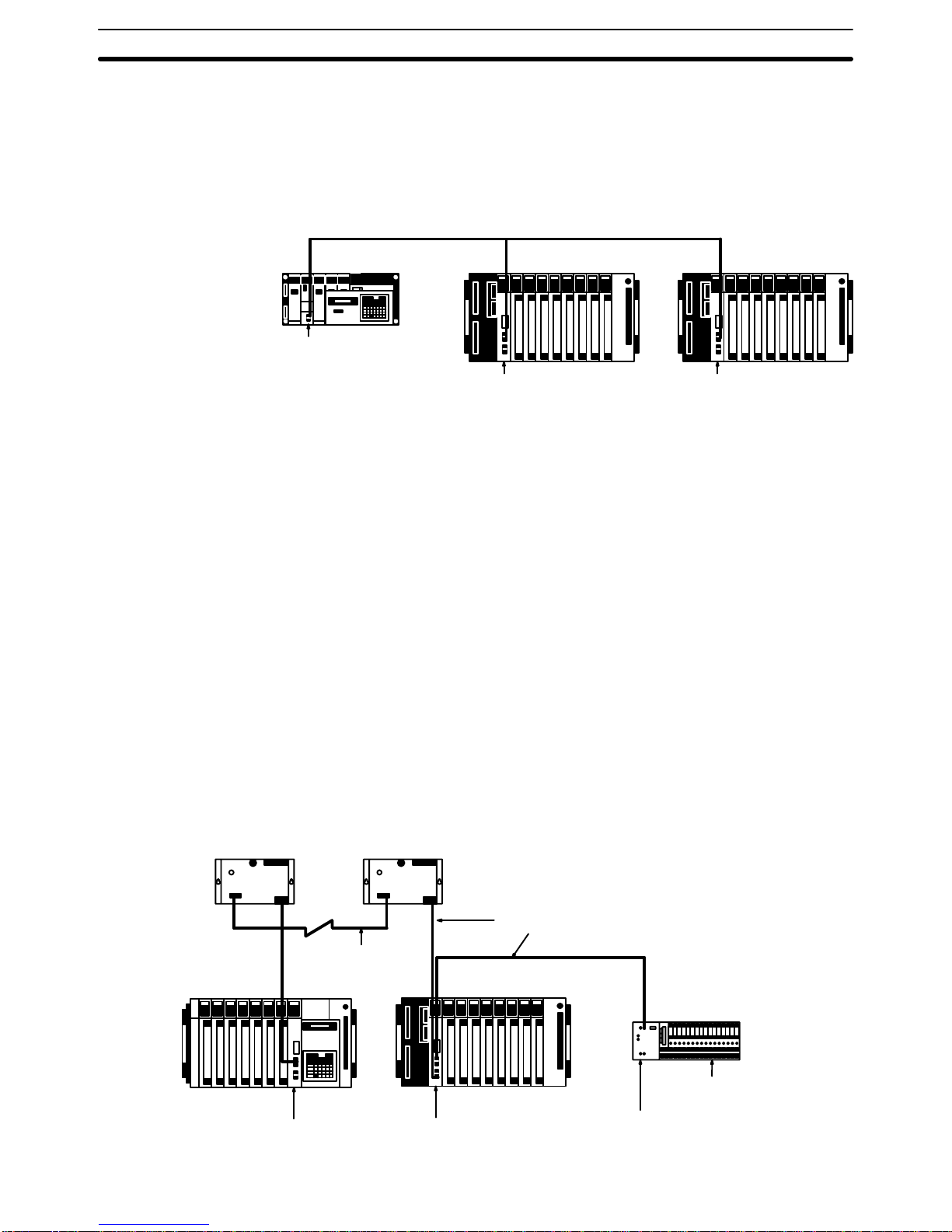
1-2 Wired Remote I/O Systems
In a Wired Remote I/O System, the Master is connected to other Remote I/O
Units through wire cable. These Remote I/O Units include Wired Masters,
Wired Slaves, and Remote Terminals. Link Adapters can also be included in
the System to enable the use of optical cable links.
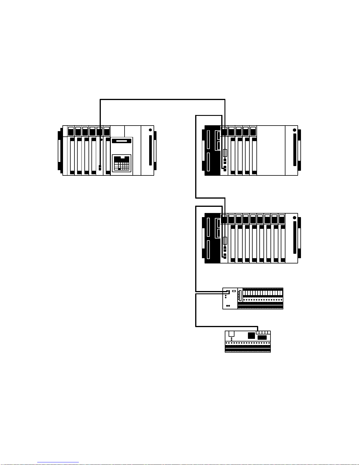
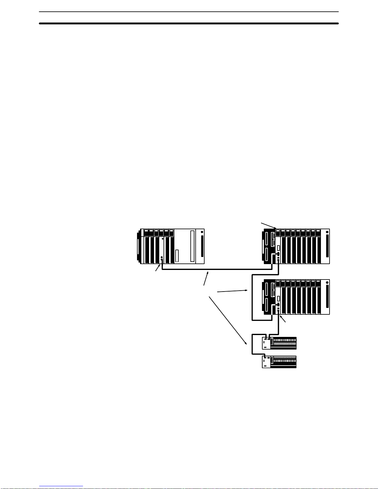
A basic Wired Remote I/O System is shown below.
C2000H CPU Rack Slave Rack
Slave Rack
Remote
Terminal
Remote
Terminal
Master
Slave
Slave
Wire cable
A Remote Terminal can be used when there is only a limited number of I/O
points required in a single location. Each Remote Terminal provides up to 16
input or output points.
There are two basic types of Remote Terminal. A G72C Remote Terminal is a
‘stand-alone’ Unit that occupies one location in the Remote I/O System. It
provides 16 fixed transistor inputs or outputs and can be used for any application suited to these.
Remote Terminals
Page 18
5
Wired Remote I/O Systems Section 1-2
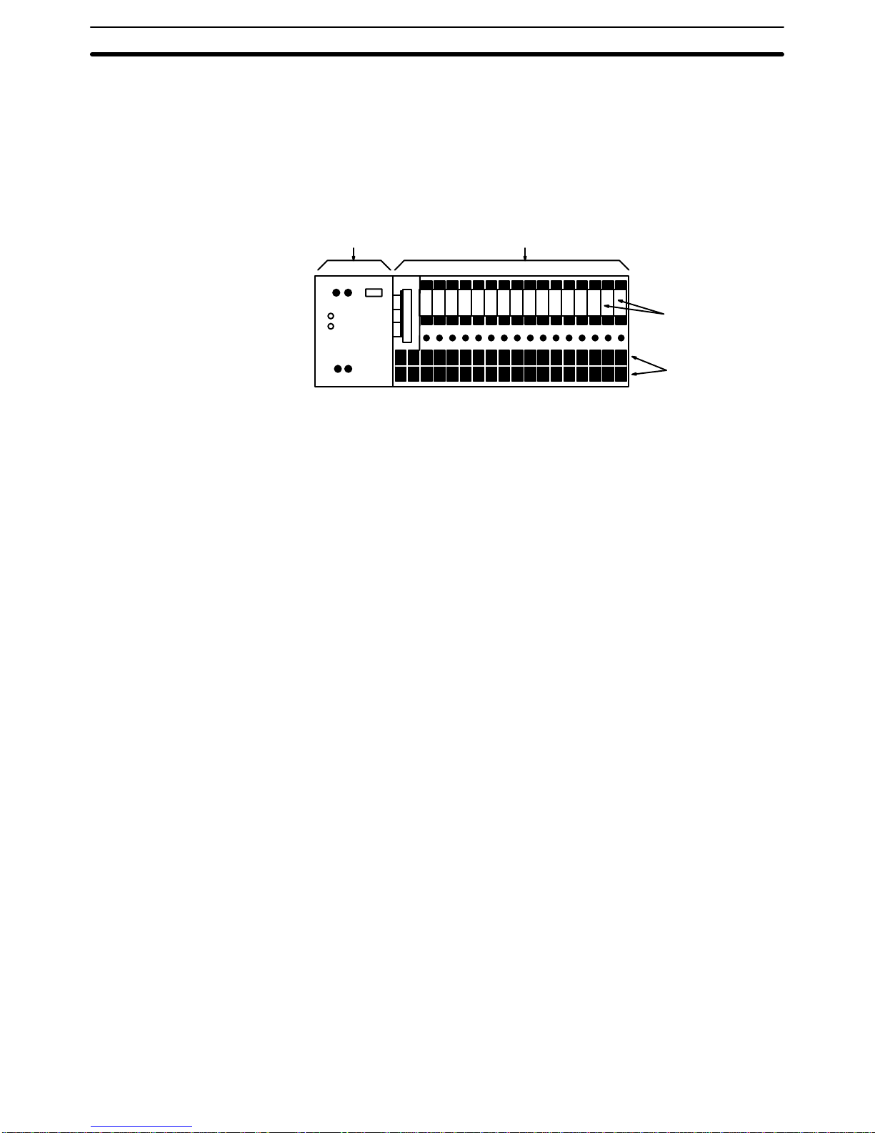
The other basic type of Remote Terminal consists of two parts: a Remote
Interface and an I/O Block. The Remote Interface functions to transmit input
or output signals between the Remote I/O System and the I/O Block. I/O
Blocks enable easy removal and replacement of individual relays, including
relays with a large switching capacity, making them ideal for controlling
large motors, heavy equipment, etc. An I/O Block is available for either 16
input points or 16 output points.
Remote Interface Input Block
Replaceable
relays
Terminals
The types of field devices that can be handled is the only functional difference between G72C Remote Terminals and Remote Interfaces connected to
I/O Blocks. There is no difference that affects the software operation of the
Remote I/O System. In the remainder of this manual, the term Remote Terminal will be used to refer collectively to both types of Remote Terminals unless
there is a reason to specify one or the other.
Converting Link Adapters can be used to create optical cable links within an
otherwise Wired System. The connections to Masters, Slaves, and Remote
Terminals are still wire cable; the optical connections are only between Link
Adapters. Refer to 2-4 Optical Connections in Wired Systems for details.
Branching Wired Remote I/O Systems through Branching Link Adapters is
not possible.
Link Adapters
Page 19

7
SECTION 2
System Design
Although there are many possible Remote I/O Systems that can be built out of Masters, Slaves and Remote Terminals,
each System is limited by the capacity of the PC and the nature of the other Units in the System. Section 2-1 describes
System configurations based on the C500-RM201 Master and C500-RT201 Slave (i.e., for C120, C500, C1000H, and
C2000H Systems), and outlines connection requirements, mounting restrictions, and System size limitations. Section 2-2
provides the same information for C200H Systems. Section 2-3 explains combining Masters and Slaves from different
Systems. Finally, Section 2-4 describes how to incorporate optical links into Wired Remote I/O Systems.
2-1 Basic System 8. . . . . . . . . . . . . . . . . . . . . . . . . . . . . . . . . . . . . . . . . . . . . . . . . . . . . . . . . . . .
2-1-1 C120 Systems 11. . . . . . . . . . . . . . . . . . . . . . . . . . . . . . . . . . . . . . . . . . . . . . . . . . . .
2-1-2 C500 Systems 12. . . . . . . . . . . . . . . . . . . . . . . . . . . . . . . . . . . . . . . . . . . . . . . . . . . .
2-1-3 C1000H and C2000H Systems 13. . . . . . . . . . . . . . . . . . . . . . . . . . . . . . . . . . . . . . .
2-2 C200H Systems 14. . . . . . . . . . . . . . . . . . . . . . . . . . . . . . . . . . . . . . . . . . . . . . . . . . . . . . . . . .
2-3 Combined Systems 16. . . . . . . . . . . . . . . . . . . . . . . . . . . . . . . . . . . . . . . . . . . . . . . . . . . . . . . .
2-4 Optical Connections in Wired Systems 17. . . . . . . . . . . . . . . . . . . . . . . . . . . . . . . . . . . . . . . .
2-5 Multilevel Systems 18. . . . . . . . . . . . . . . . . . . . . . . . . . . . . . . . . . . . . . . . . . . . . . . . . . . . . . . .
Page 20

Basic System Section 2-1
8
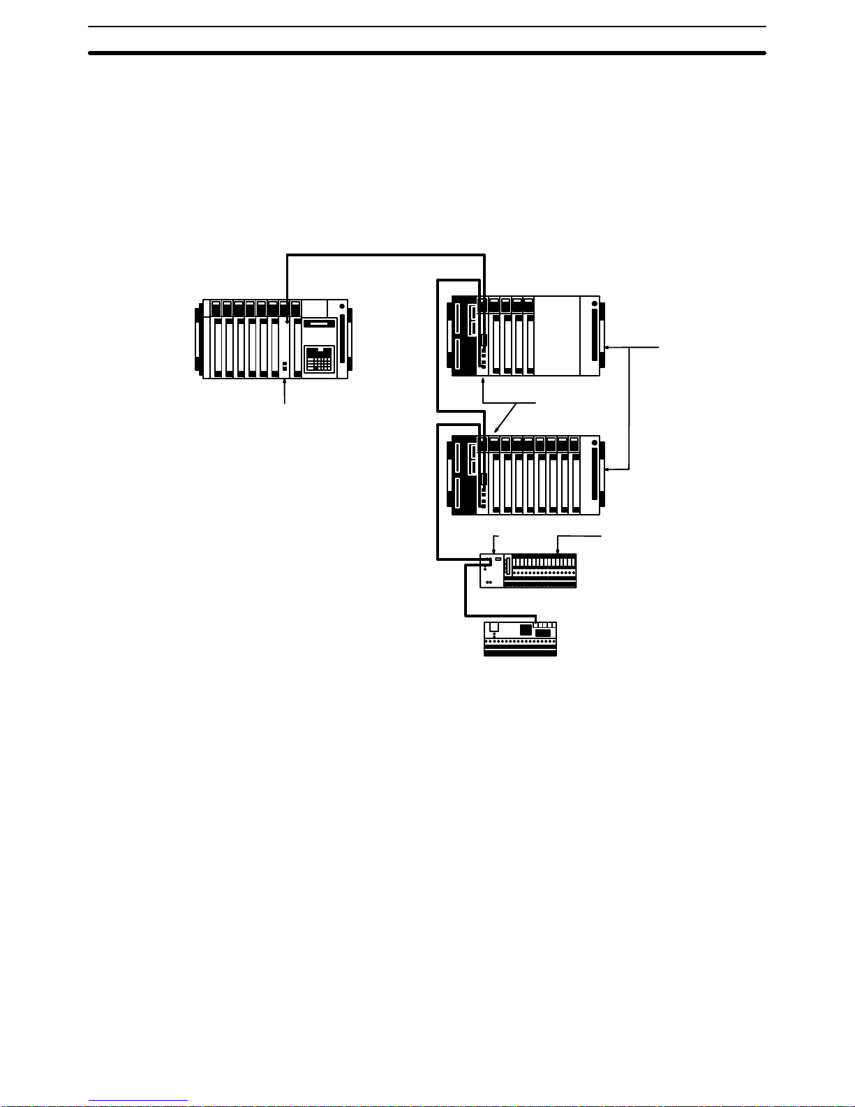
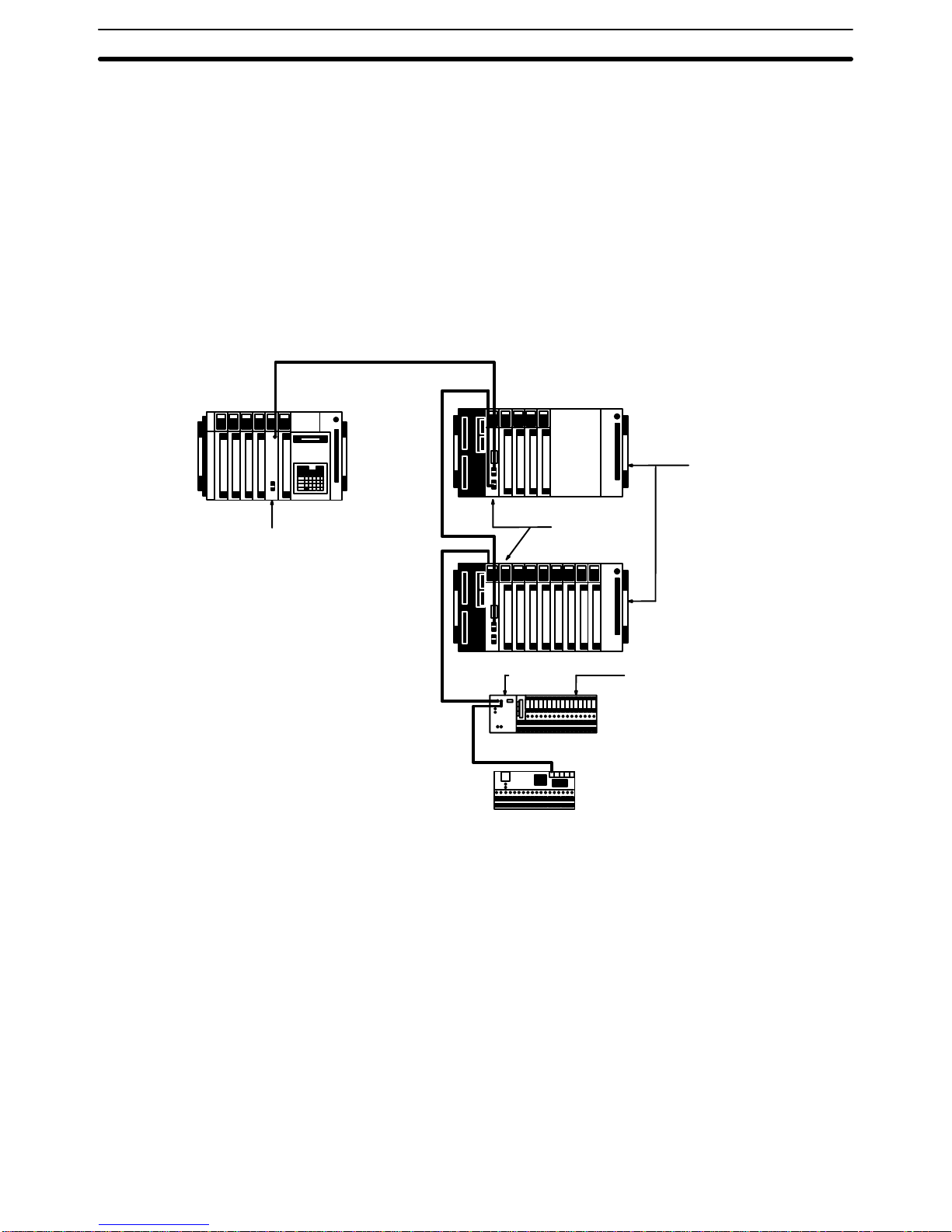
2-1 Basic System
The following figure shows a basic System configuration illustrating some
aspects of Wired Remote I/O Systems designed with the C500-RM201 Master. Refer to following subsections for specific examples and limitations.
C500(F), C1000H(F),
C2000H, CV500, CV1000,
CV2000, CVM1 CPU Rack
2-conductor cable
Slave Racks
Wired Slaves
C500-RT201
Remote Terminal
I/O Block
Remote Terminal
Wired Master
C500-RM201
At least one Master is always necessary to connect Slaves and/or Remote
Terminals. Connect each Master and all the Remote I/O Units controlled
through it in series. All Units can be combined in any fashion and connected
in any order as long as they are in series and the Master is on one end of the
line. I/O Blocks are mounted to Remote Interfaces.
Masters can be mounted to any I/O slot on the CPU or Expansion I/O Rack in
all but C120 Systems. In C120 Systems, Masters must be mounted to the I/O
Interface Unit’s position (leftmost slot) on C500 Backplanes.
Unit Connection
Mounting Remote I/O Units
Page 21
Basic System Section 2-1
9
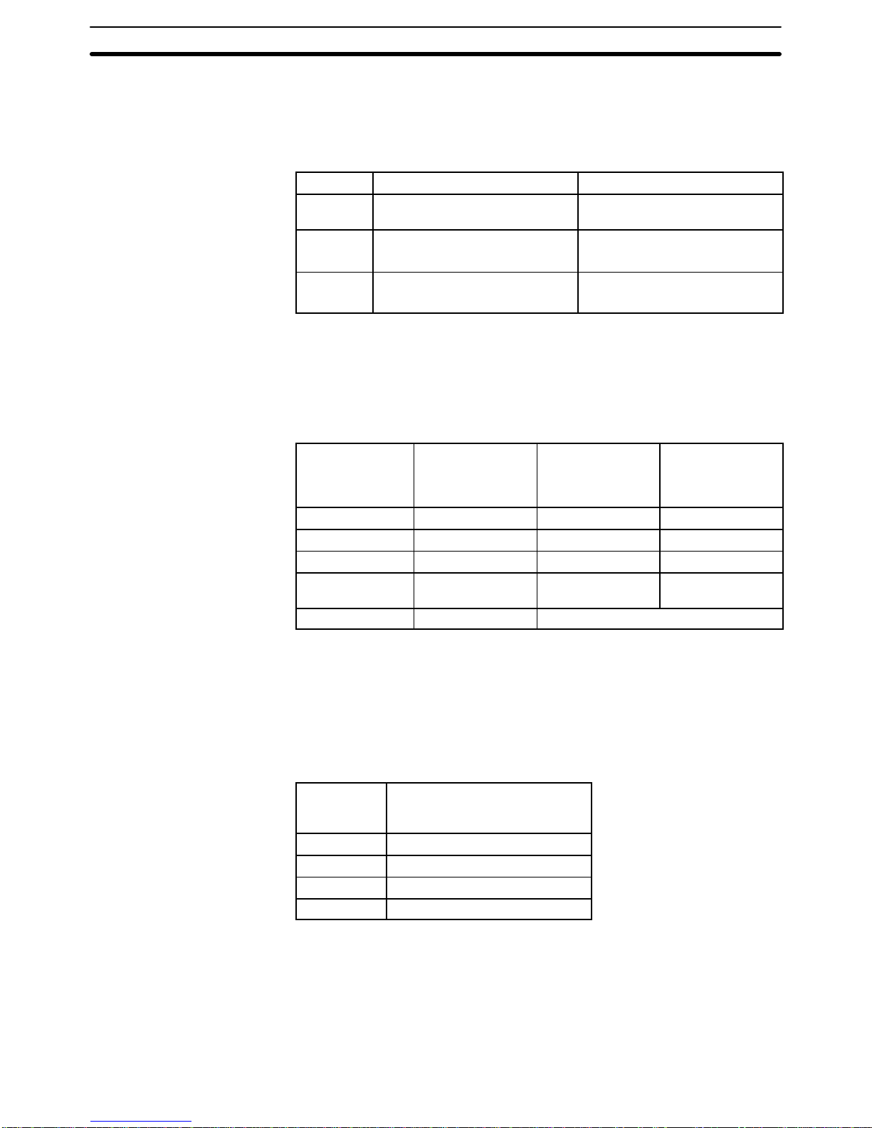
Remote Interface and I/O Blocks are used in pairs, each of which provides
16 points. The I/O Block is easily connected to the Remote Terminal by way
of a connector. G72C Remote Terminals, on the other hand, do not require a
separate I/O Block. Remote Interface and I/O Blocks are paired as follows:
I/O I/O Block Remote Terminal
AC Input G7TC-IA16 100/110 VAC or
G7TC-IA16 200/220 VAC
G71-IC16 12 VDC or G71-IC16
24 VDC
DC Input G7TC-ID16 12 VDC
G7TC-ID16 24 VDC
G71-IC16 12 VDC
G71-IC16 24 VDC
Output G7TC-OC16 12 VDC
G7TC-OC16 24 VDC
G71-OD16 12 VDC
G71-OD16 24 VDC
The number of Units in any one System is limited by the capacity of the PC.
Detailed limitations are provided in the following table. These totals include
all Optical and Wired Master Subsystems controlled by the PC.
PC C120 C500, CV500,
CVM1-CPU01-EV2
C1000H, C2000H,
CV1000, CV2000,
CVM1-CPU11-EV2
/CPU21-EV2
Masters per PC 4 4 8
Slaves per Master 2 2 8 (see note)
Slaves per PC 8 8 16 (see note)
Remote Terminals
per Master
16 32 32
Words per Master 16 (256 points) 32 (512 points)
Always set the address number of the Remote I/O Unit in order starting from
#0. The CPU Unit will determine the number of Slaves connected according
to the address number of the Remote I/O Unit, as shown in the following
table, even if only one Slave is actually connected. Therefore, if the address
number is designated from the larger number, the actual total number of Remote I/O Units that can be connected to one PC will be limited.
Largest Unit
No. Set
Number of Slaves Connected
(as Determined by the CPU
Unit)
0 or 1 2
2 or 3 4
4 or 5 6
6 or 7 8
If three Slaves connected to separate Masters mounted to the same CPU
Rack were set as Unit number 4, the PC would assume, as shown above,
that each Master had six Slaves attached, for a total of 18, or two more than
allowed in the System. An error would thus be generated, even if the three
Slaves were actually the only Slaves in the System.
Remote Terminals
Maximum Number of
Connectable Remote I/O
Units
Note
Example
Page 22

Basic System Section 2-1
10
The total number of I/O points in the System must not exceed the number of
I/O points provided by the PC to which the Master(s) is mounted or
connected.
PC Maximum Number of I/O Points
C2000H 2,048
C1000H 2,048*
C500 512
C120 256
*The total number of I/O points in a C1000H System can be up to 2,048, as
long the number of I/O points on the CPU Rack and Expansion I/O Racks
connected to the CPU Rack (i.e., not I/O points on Slave Racks) is limited to
1,024.
Total number of points for the PC
Total number of points on CPU Racks and
Expansion I/O Racks
Total number of points on Slave Racks
Total number of points on Remote Terminal
+
=
+
+
Total number of points in Optical Remote Subsystems
Total I/O Points
Page 23
Basic System Section 2-1
11
2-1-1 C120 Systems
In C120 Systems, up to four Masters can be connected to the same PC, and
up to two Slaves and 16 Remote Terminals can be connected to any one
Master. Note that a Master in a C120 System must be mounted to an I/O slot
on a C500 Expansion I/O Rack.
C120 PCs provide 256 I/O points. This means that the total number of points
used in the System must be 256 or less. If, for example, 256 points are controlled by one Master connected to a C120 PC, there cannot be any more
Masters or I/O points employed for that C120 PC.
C120 CPU Rack
C500 Expansion
I/O Rack
C500 Master
C500-RM201
C500 Slaves
C500-RT201
Slave Racks
Remote Interface
G7TC I/O Block
Remote Terminal
Page 24
Basic System Section 2-1
12
2-1-2 C500 Systems
In C500 Systems, up to four Masters can be connected to the same PC, and
up to two Slaves and 32 Remote Terminals can be connected to any one
Master.
C500 PCs provide 512 I/O points. This means that the total number of points
used in the System must be 512 or less. If, for example, 512 points are controlled by one Master connected to a C500 PC, no more Masters or I/O
points can be employed for that C500 PC.
Remote Interface
I/O Block
Remote Terminal
Slave
Racks
C500 CPU Rack
C500 Master
C500-RM201
C500 Slaves
C500-RT201
Page 25
Basic System Section 2-1
13
2-1-3 C1000H and C2000H Systems
In C1000H and C2000H Systems up to eight Masters can be connected to
the same PC. In C1000H and C2000H Systems, up to eight Slaves and 32
Remote Terminals can be connected to any one Master.
When a Remote I/O System is included, C1000H and C2000H PCs provide
2,048 I/O points. This means that the total number of points used in the System must be 2,048 or less. If, for example, 2,048 points are controlled by four
Masters on C1000H and C2000H PCs, no more Masters or I/O points can be
employed on the PCs. (The number of I/O points for the I/O Units on a
C1000H CPU Rack and Expansion I/O Racks must be kept to within
1,024.)The number of points for any one Master, must be kept to 512 or less.
Remote Interface
I/O Block
Remote Terminal
Slave Rack
C1000H
or
C2000H
CPU
Rack
C500 Master
C500-RM201
C500 Slaves
C500-RT201
Page 26

C200H Systems Section 2-2
14
2-2 C200H Systems
When constructing a Remote I/O System from C200H Masters and Slaves,
up to 2 Masters, 5 Slaves (regardless of the number of Masters), and 32 Remote Terminals can be included. Optical Masters and Slaves, if controlled by
the PC, must be included in these totals. Expansion I/O Racks can be connected to Slave Racks, however this limits the number of Slaves which the
PC can control i.e., each such Expansion I/O Rack must be counted as a
Slave Rack. The basic rules for Remote I/O Systems apply, e.g., each Master
Subsystem must be connected in series with a Master on one end and a terminator (either a Remote Terminal or Slave) on the other end.
Masters can be mounted to any slot on the C200H CPU Rack or Expansion
I/O Rack. Masters should not be mounted, however, to either of the rightmost
two slots of the CPU Rack, as this would prevent mounting devices directly to
the CPU Unit. I/O Blocks are mounted to the Remote Interface, just as in
Systems using C500-RM201 Masters (see 2-1 Basic System). Masters
cannot be mounted to Slave Racks or to Expansion I/O Racks connected to
Slave Racks
Note 1. The only Units that can be mounted to Remote I/O Slave Racks are Basic
I/O Units and Special I/O Units.
2. High-density I/O Units (Group 2) and B7A Interface Units (Group 2) cannot
be used on Remote I/O Slave Racks.
3. A Remote I/O Master Unit cannot be used if the CPU Unit is the
C200H-CPU02.
4. High-density I/O Units mounted on a Remote I/O Slave Rack can be used
only if the Remote I/O Master Unit is the C200H-RM201.
The numbers of Special I/O Units that can be mounted to any one Slave
Rack are shown in the following table. These figures assume that Units are
used only from one of the three groups.
Group A
Group B Group C Group D
High-Speed Counter Unit Multi-Point I/O Temperature Sensor
Voice Unit
Position Control Unit
(C200H-NC211, C200HWNC413)
Motion Control Unit (C200HMC221)
Position Control Unit
(C200H-NC111/112,
C200HW-NC113/213)
ASCII Unit
Analog I/O Units
--- --- ---
4 total 8 total 6 total 2 total
If Units from more than one group are used, the following equations must be
met:
3A + B + 2C + 6D ≤ 12
A + B + C + D ≤ 8
The total number of Special I/O Units that can be used on all Racks com-
bined is 10. If PC Link Units are also used in the PC System, they must also
be included in the total.
Transmission time will be decreased with the same number of Slaves if two
Masters are used rather than one. Refer to Section 6 I/O Response Times.
Mounting Locations
Special I/O Units
Transmission Time
Page 27
C200H Systems Section 2-2
15
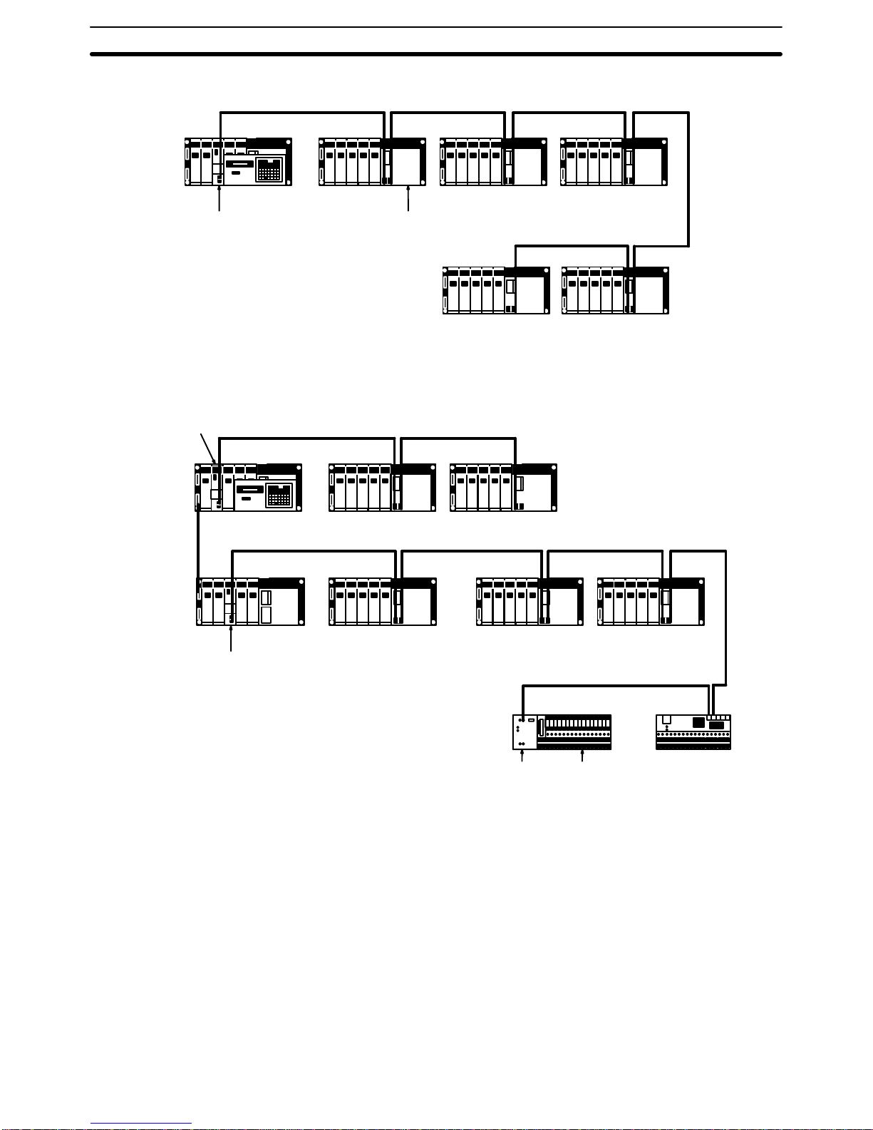
Example System 1: One Master
Slave Rack Slave Rack Slave Rack
Slave RackSlave Rack
C200H SlaveC200H Master
C200H PC
Example System 2: Two Masters
Remote Interface I/O Block
Remote Terminal
Slave Rack Slave Rack
Slave Rack
Slave Rack
C200H PC
Expansion
I/O Rack
C200H Master
C200H Master
Slave Rack
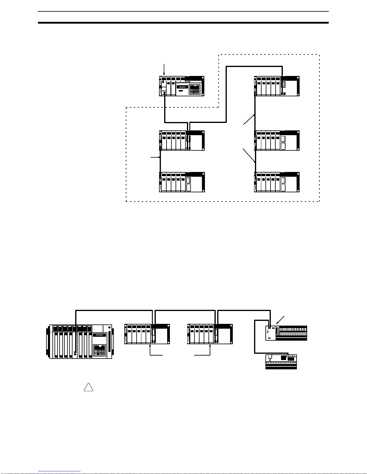
A maximum of two C200H Expansion I/O Racks can be connected to a Slave
Rack. I/O Connecting Cable (2-conductor cable) is used to connect the extra
Expansion I/O Racks.
Example System 3: Master
with Extra Expansion I/O
Racks
Page 28
Combined Systems Section 2-3
!
16
Individual sections of cable must not be longer than 2 m. Each extra Expansion I/O Rack must be counted as a ‘Slave’ when computing the number of
Slaves controlled by the PC.
I/O Connecting
Cable
I/O Connecting
Cable
Slave Rack
Slave Rack
Expansion I/O Rack
Expansion I/O Rack
Expansion I/O Rack
C200H PC
C200H Master
2-3 Combined Systems
C500 and C200H Remote I/O Units can be combined into the same System.
That is, C500 Slaves can be connected to C200H Masters; C200H Slaves, to
C500 Masters.
The maximum number of connectable Units is the same as in any Remote
I/O System based on the C500-RM201 (see 2-1 Basic System). Word
assignments will be based on the C500 PC, i.e., based on the order and
positions of I/O Units mounted, and not on fixed slot words. Special I/O Units
cannot be mounted to C200H Slave Racks controlled by a C500 Master; all
mounted Units will be assigned only one word each. The “type of Master”
switch an all C200H Slaves controlled by C500 Masters must be turned ON
to designate a Master other than the C200H Master.
C-Series
PC other
than the
C200H
C200H
Slave Rack
C200H Slave
Remote Interface
G7TC I/O
Block
Remote Terminal
C200H
Slave Rack
C500 Master
Caution When C200H Slave Racks are connected to Masters on PCs other than the
C200H/C200HS, all Output Units on these Slave Racks will be treated as having
at least 16 output points. disabling the Fuse-burnout and Alarm Detection Bits on
Units that normally provide them (e.g., C200H-OD411, C200H-OD213,
C200H-OD214, and C200H-OA221).
When using the C200H Backplane for 10 slots as a remote I/O Slave for the
CVM1/CV500/CV1000/CV2000, only the 8 slots from the left can be used; the
9th and 10th slots from the left cannot be used.
Example 1: C500 Master
and C200H Slaves
Page 29
Optical Connections in Wired Systems Section 2-4
17
When connecting C500 Slaves to C200H Masters, each C500 Slave must be
counted as 2 Slaves when figuring the total number of Slaves. This total,
which includes all optical and wired Slaves, must be no greater than 5 for any
one C200H PC. Here, Special I/O Units can be mounted to C500 Slave
Racks. Word assignments will be based on the C500 PC’s System, i.e.,
based on the order and positions of I/O Units mounted (starting at the left),
and not on fixed slot words.
C200 Master
C500 Slave
C500 Slave Rack
C200H PC
C500 Slave
C500 Slave Rack
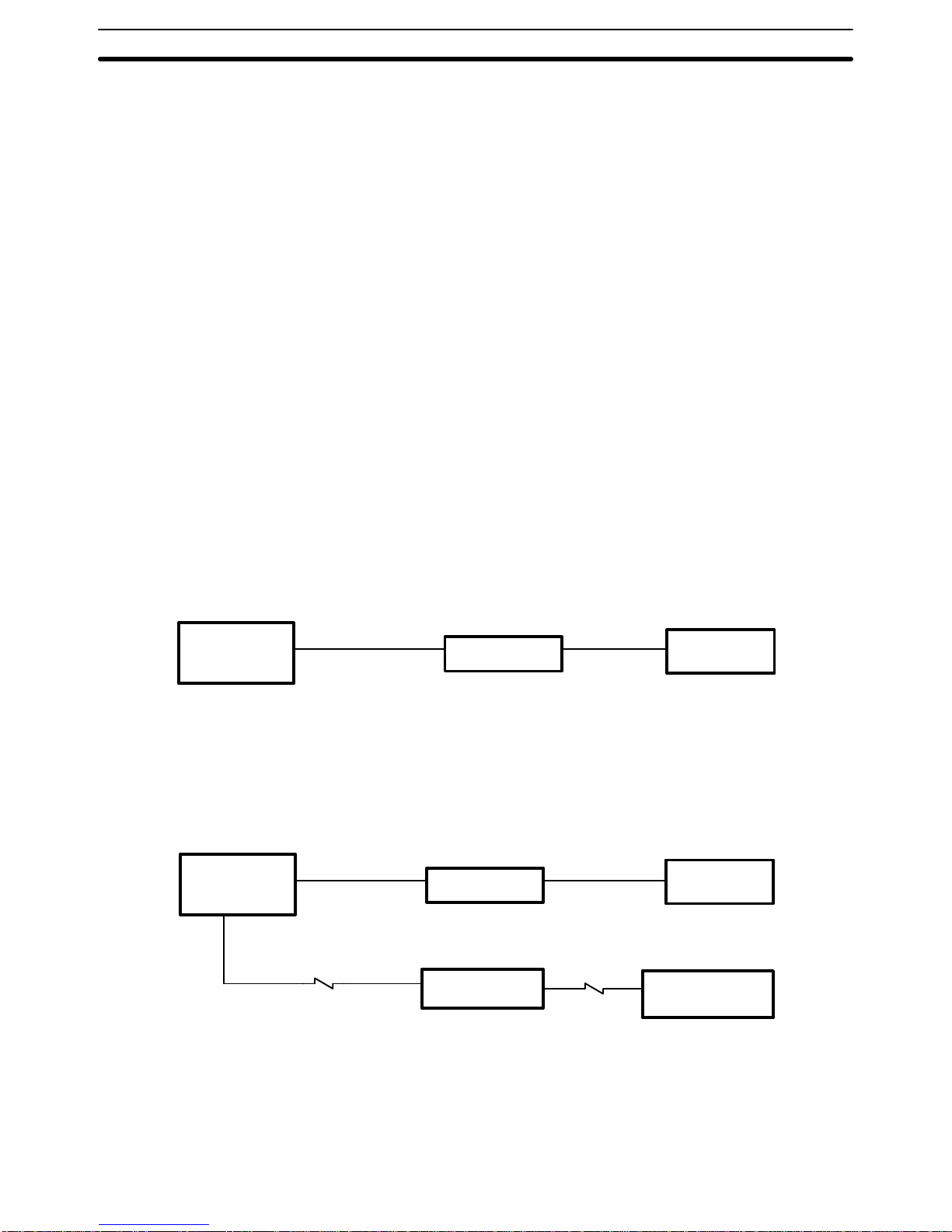
2-4 Optical Connections in Wired Systems
Two B500-AL007-P Link Adapters can be used to extend the transmission
distance and/or to prevent interference from noise by inserting an optical link
between two Remote I/O Units. The two Link Adapters convert between wire
and optical signals, transmitting over the optical link between them. The
AL007-P Link Adapter is thus always used in pairs, and always between
Wired Remote I/O Units. The entire Master Subsystem, from Master to terminator, must still be connected in series.
Up to 8 Link Adapters (4 pairs) can be used for each Master. To take full advantage of an optical link, shorten wire links as much as possible, even to the
point of placing the Link Adapter on the same control panels as the Remote
I/O Units.
Maximum cable length for any one section of optical cable is 20 m for
all-plastic optical fiber cable (APF); 200 m for plastic clad optical fiber cable
(PCF).
Refer to the Link Adapter manual for details on this and other uses of Link
Adapters.
Link Adapter
B500-AL007-P
Link Adapter
B500-AL007-P
APF/PCF
optical
cable
RS-485
cable
C500 CPU Rack
C500 Master
C500 Slave
C500 Slave Rack
RS-485 cable
Remote
Interface
Terminator
I/O Block
Example 2: C200H Master
and C500 Slaves
Page 30

Multilevel Systems Section 2-5
18
Although special characteristics of optical fibers call for care in connecting
optical devices, laying optical fiber cables basically does not differ from laying
wire cables. All OMRON PCF Cables and the 3G5A2-PF101 APF (length: 1
m) Cable come with connectors attached. Connectors for all other APF
Cables must be assembled by the customer. Note the following precautions
when handling optical fiber cables:
1. Always turn the power off to the Link Adapter when connecting or disconnecting an optical fiber cable.
2. Always hold the connect when disconnecting an optical fiber cable;
never pull on the cable.
3. APF and PCF connectors are designed to be inserted only in one direct;
do not try to force them in the wrong way.
4. Insert APF and PCF connectors until they lock into position.
5. Always place the protective caps on unused Link Adapter modules.
6. If dirty, clean connectors gently with a tissue or sanitary cotton, using
ethyl alcohol if necessary. Do not use any solvent other than ethyl alcohol.
7. Do not allow heavy objects to fall on optical cable or otherwise subject it
to excessive shock or strain.
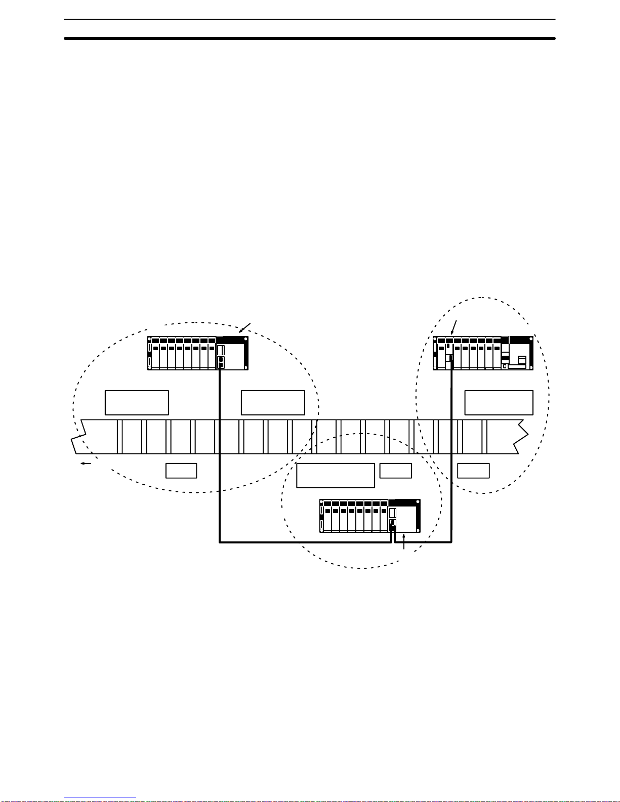
2-5 Multilevel Systems
There is no reason that a Remote I/O System must remain restricted to either
wired or optical communications. PCs support multiple Masters, some of
which can be Wired and some of which can be Optical.
Although the number of Subsystems supported by each PC is limited, each
Subsystem can be considered independently from the others as long as the
total capacity of the PC is not exceeded. It is important to note that although
both Wired and Optical Masters can be controlled by the same CPU Unit,
Optical and Wired Remote I/O Units cannot be combined in the same Subsystem, i.e., Optical Masters can be connected only to Optical Slaves, Optical I/O Units, and I/O Link Units; Wired Masters can be connected only to
Wired Slaves and Remote Terminals.
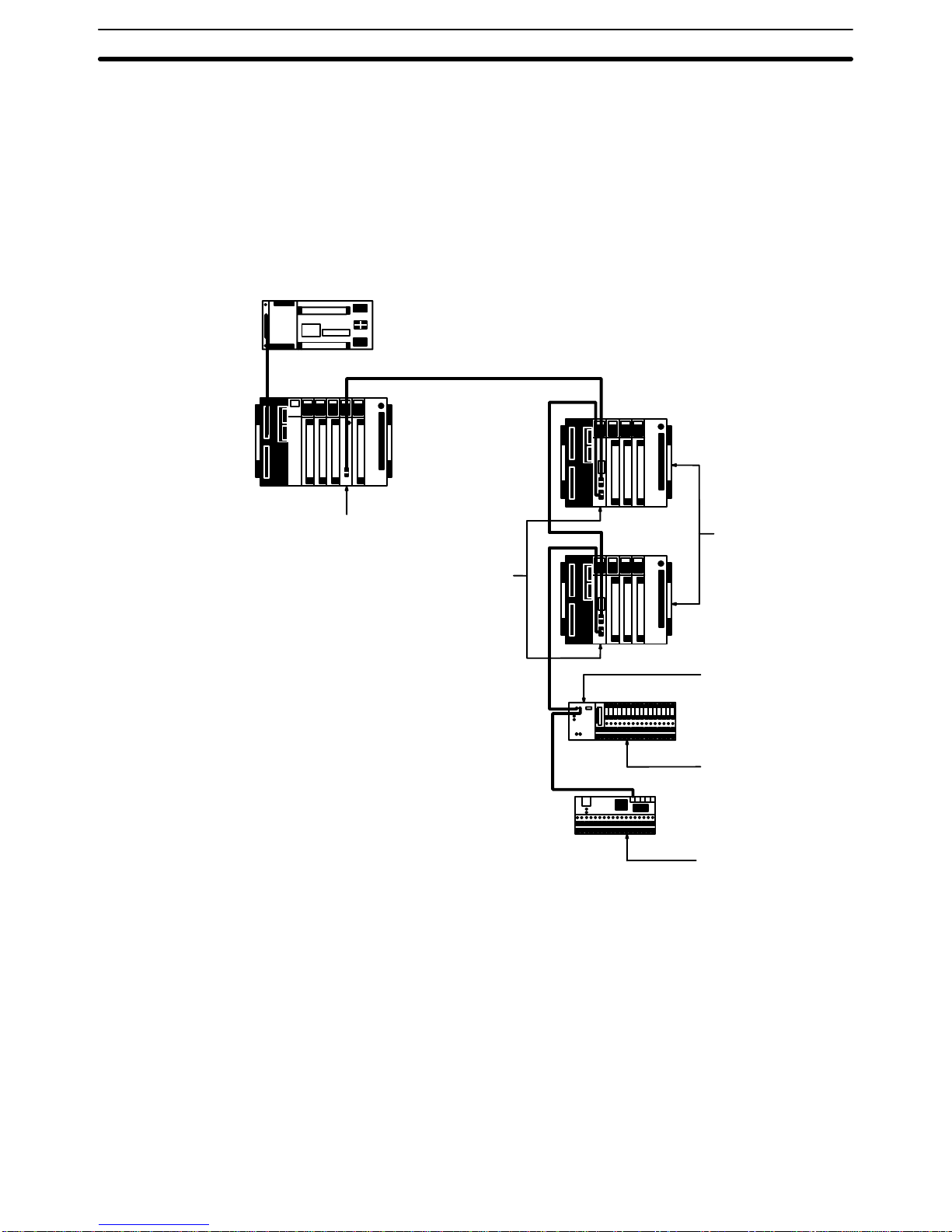
In the following example, two CPU Racks are used. The one in the upper left
corner controls two Remote I/O Subsystems, one Wired and one Optical.
The Optical System contains an I/O Link to the other CPU Rack (at the right),
which has one Remote I/O Subsystem controlled by it.
The Optical I/O Units, Slave Rack, and Expansion I/O Rack beneath the CPU
Rack at the right are controlled through the Optical Master on this CPU Rack.
Note that if there was no Master on this Rack and the Optical I/O Units and
Slave Rack were connected through the I/O Link Unit, they would become
the last Units in the Optical Remote I/O Subsystem controlled by the CPU
Unit at the upper left, and be controlled by it.
Handling Optical Fiber
Cable
1, 2, 3...
Page 31

Multilevel Systems Section 2-5
19
Another aspect of Remote I/O Systems demonstrated by this diagram is the
presence of Expansion I/O Racks, both connected to a CPU Rack and to
Slave Racks. Although normally not shown in system diagrams for Link Systems, Expansion I/O Racks can be used to increase the number of I/O Units
mountable at any one location.
C200H CPU Rack
Expansion I/O Rack
Expansion I/O Rack
Expansion I/O Rack
C200H Optical Slave Rack
Remote
Terminal
Remote
Terminal
C500 Wired Slave Rack
Optical I/O Units
C2000H
CPU Rack
C200H Wired Slave Rack
C200H Optical Slave Rack
Optical Slave
Optical
Slave
Optical Master
Wired Master
Optical cable
Wire cable
Wire cable
Wire cable
Wire cable
Wired
Slave
Optical
Master
I/O Link Unit
Wired
Slave
Optical cable
Optical cable
Optical cable
Wire cable
Wire cable
Wire cable
Wire cable
Optical cable
Page 32

21
SECTION 3
Data Exchange and Operations
PCs transmit I/O data through Masters, Slaves, and Remote Terminals according to allocated words.
Although words are not allocated to Masters and Slaves, they are allocated to all I/O Units and Remote Terminals in the
System. To enable proper word allocation, Unit numbers must be set for all Slaves and, in some Systems, word multipliers must be set for Masters. A Slave or Remote Terminal must also be set as a terminator for each Master.
Section 3-1 provides block diagrams of various Remote I/O Units. Section 3-2 provides details and examples of Unit
connections, word settings, terminator settings, word multiplier registration, and the word allocations that result from
these. The basic setting procedure for the entire System is outlined in Section 3-3. Finally, Section 3-4 provides example
program sections used to start System operation when power is turned on to a Slave, rather than to the Master as it normally is.
3-1 Block Diagrams 22. . . . . . . . . . . . . . . . . . . . . . . . . . . . . . . . . . . . . . . . . . . . . . . . . . . . . . . . . .
3-2 Unit Numbers and I/O Word Allocation 25. . . . . . . . . . . . . . . . . . . . . . . . . . . . . . . . . . . . . . .
3-2-1 C500 Masters 26. . . . . . . . . . . . . . . . . . . . . . . . . . . . . . . . . . . . . . . . . . . . . . . . . . . . .
3-2-2 C200H Masters 34. . . . . . . . . . . . . . . . . . . . . . . . . . . . . . . . . . . . . . . . . . . . . . . . . . .
3-2-3 Combined Systems 37. . . . . . . . . . . . . . . . . . . . . . . . . . . . . . . . . . . . . . . . . . . . . . . .
3-3 Setting Procedure 39. . . . . . . . . . . . . . . . . . . . . . . . . . . . . . . . . . . . . . . . . . . . . . . . . . . . . . . . .
3-4 Delayed Activation of Slaves 41. . . . . . . . . . . . . . . . . . . . . . . . . . . . . . . . . . . . . . . . . . . . . . . .
Page 33

22
Block Diagrams Section 3-1
3-1 Block Diagrams
The following block diagrams are for Units available in Wired Remote I/O
Systems.
C500 Master and Slave
PC
interface
Bus
controller
Transmission
interface
CPU
Common
RAM
C120,
C500,
C1000H,
or
C2000H
CPU Unit
System
ROM
I/O
interface
DC-DC
converter
Indicators
Switches
Master
PC I/O
interface
Transmission
interface
CPU
System
ROM
I/O
interface
DC-DC
converter
DIP
switch
Slave
Work
RAM
Relay
output
2-conductor
cable
Switches
RUN output
Indicators
RS-485
interface
RS-485
interface
Backplane
Page 34

23
Block Diagrams Section 3-1
C200H Master and Slave
RS-485
interface
Transmission
interface
DC-DC
converter
C200H
Backplane
CPU
Data
memory
Power
section
Slave
System
memory
Work
memory
I/O
interface
Indicators
RS-485
interface
Transmission
interface
DC-DC
converter
C200H,
C200HX,
C200HG,
C200HE,
or
C200HS
CPU Unit
CPU
Master
System
memory
Work
memory
I/O
interface
Indicators
Switches
C200H PC
interface
Indicators
Switches
C200H PC
interface
2conductor
cable
RUN output
Power supply
X
Page 35

24
Block Diagrams Section 3-1
Remote Interface and I/O Blocks
I/O Block
Remote Interface
Protection
circuit
Indicators
Relay interface
I/O
devices
Power supply 12 or 24 VDC
I/O
interface
Transmission
interface
CPU
System
ROM
I/O
interface
Indicators
DIP
switch
Work
RAM
Relay
output
RUN output
RS-485
interface
Switches
DC-DC
converter
Page 36

25
Unit Numbers and I/O Word Allocation Section 3-2
G72C Remote Terminal
Power supply
12 or 24 VDC
I/O
devices
I/O
interface
Transmission
interface
CPU
System
ROM
I/O
interface
Indicators
DIP
switch
Work
RAM
Relay
output
RUN output
RS-485
interface
Switches
DC-DC
converter
AL007-P Link Adapter
Code
converter
Electrical-optical
converter
To other AL-007
Link Adapter
+ –
5V
0V
Fuse
To Wired Remote I/O Unit
or Remote Terminal
AC power supply
100 to 240 VAC
LG
FG
Line and frame
grounds
3-2 Unit Numbers and I/O Word Allocation
Word allocations on Racks in Remote I/O Systems follow basically the same
pattern as the PC to which the Master is mounted, i.e., by the mounting order
of and by the number of words required for each Unit mounted for C120,
C500, C1000H, and C2000H Systems and by fixed slot words in C200H Systems.
Basic Allocation
Page 37

26
Unit Numbers and I/O Word Allocation Section 3-2
In either case, allocations start from the lowest word starting on the left side
of the CPU Rack. When a Master is reached on a Rack, allocation jumps to
the leftmost Unit mounted on the first Slave Rack connected to the Master,
and then to the second Slave Rack, etc, until the terminator is reached. Then
allocations return to the Unit following the Master and continue across the
CPU Rack and Expansion I/O Racks until all the Units on all Racks have
been allocated. Details on and examples of allocation are provided below.
Words for Units not mounted to Racks (i.e., Remote Terminals) are not determined as described above, but according to switch settings on the Units, as
described below.
There must be one terminator set for each Master, and it must be the Unit at
the opposite end of the I/O bus from the Master.The terminator may be a
Slave or a Remote Terminal. The Master checks for a terminator immediately
upon power application. If the terminator is properly set, the other Units connected to the I/O bus are acknowledged. All following operation is based on
this initial check. Therefore, if a Unit is not attached properly or if the power
to a Unit is not on when this check is performed, that Unit will be ignored during actual operation.
3-2-1 C500 Masters
Because more than one Slave can be attached to each Master, Unit number
settings are necessary to distinguish the Slaves. Unit numbers 0 through 7
can be set for C1000H and C2000H, Slaves; unit numbers 0 and 1, for all
others. The Slave assigned unit number 0 is referred to as Slave #0; the
Slave assigned unit number 1, as Slave #1, etc. The same unit number cannot be used on more than one Slave under the same Master. Setting unit
numbers other than those listed above will prevent Slave operation.
Set the Slave directly connected to a Master as Slave #0, the Slave connected to Slave #0 as Slave #1, and so on. Setting unit numbers and a terminator is necessary for every Master, even when only one Slave is connected.
Refer to Section 4 Switch Settings for details on setting procedures.
I/O Units can be mounted to Slave Racks in any location desired numbers are
automatically allocated left to right in the order the I/O Units are mounted.
A PC I/O word must be allocated for each Remote Terminal connected in the
System; words are not automatically allocated. Any word from 0 through 31
can be set in all Systems but C120 Systems, where words between 0 and 15
must be set.
In C1000H and C2000H Systems, words 0 through 127 are allocated by the
PC’s CPU Unit to enable use of up to 128 words even though actual word
settings are from 0 through 31. This is achieved by combining word settings
with word multipliers, which are explained next.
Because the C1000H and C2000H PCs can handle up to 2,048 points (or
128 words), words 32 to 127 of these PCs cannot be allocated without some
identification other than word settings. It is therefore necessary to assign
word multipliers to the Masters to which Remote Terminals are mounted and
identify the words with these multipliers as well. These numbers run from 0
through 3.
Word numbers, word settings, and word allocations are related as shown by
the following equation:
I/O word allocation = (32 words x word multiplier) + (word set on Unit)
Terminator
Setting Slave Unit Numbers
and Terminators
Setting Remote Terminal
Words
Word Multipliers in C1000H
and C2000H Systems
Page 38

27
Unit Numbers and I/O Word Allocation Section 3-2
For example, suppose word 28 is set on a Remote Terminal and word multiplier 2 is assigned to the Master of that Remote Terminal. The I/O word allocated to the Remote Terminal, viewed from the PC, is computed as follows:
32 words x 2 + 28 words = word 92
A word multiplier is not assigned to a Master to which only Slaves are con-
nected because words will be automatically allocated to the I/O Units on
these Slaves. The I/O words assigned in Remote I/O Systems must not be
the same as the I/O words allocated elsewhere.
The same word multiplier can be assigned to more than one Master as long
as the word settings for the Units connected to the Masters are different, i.e.,
as long as the allocated words differ.
Page 39

28
Unit Numbers and I/O Word Allocation Section 3-2
Set the word multipliers in a C1000H and C2000H System using the Programming Console as shown below. Before setting word multipliers, set the
mode selector to PROGRAM. Word multipliers must be assigned only to the
Masters to which Remote Terminals are connected. Displays for word multipliers are not displayed for Masters to which only Slaves are connected.
Initial clear all
Register I/O table
Continue registering word multipliers
by entering them with the WRITE key.
Automatically checks I/O table.
The CPU Unit takes about 2 s
here.
Indicates word multiplier not yet specified.
Once the word has been specified
and entered with the WRITE key,
proceed to the next master.
When a word has already been registered, it
will be displayed. Press the WRITE key to
continue without changing it, or input a new
multiplier before the WRITE key to change it.
Appears when all word multipliers have
been registered, completing the operation.
Setting Word Multipliers
Page 40

29
Unit Numbers and I/O Word Allocation Section 3-2
Meaning of Displays
Requesting input of word multiplier.
Word multiplier not yet specified.
Master number (0 to 7)
Indicates a Master
I/O slot number
Rack number
Page 41

30
Unit Numbers and I/O Word Allocation Section 3-2
I/O Word Allocation Examples
The following examples show four possible Systems and the word allocations
for them. They do not show all possible connections or the maximum number
of Units possible for each System. Refer to Section 4-1 for the maximum
number of connectable Units.
With two Slaves connected to one Master, the Slaves are set to unit numbers
0 and 1. The order does not matter. The last Unit must be set as the terminator. If only one Slave is connected, set it to unit number 0 and as the terminator. Words are automatically allocated for all I/O Units.
16 pts.
32 pts.
64 pts.
16 pts.
IR 7
IR 5 & 6
IR 1, 2, 3, & 4
IR 0
32 pts.
32 pts.
16 pts.
16 pts.
IR 18 & 19
IR 16 & 17
IR 15
IR 14
32 pts.
16 pts.
16 pts.
16 pts.
16 pts.
IR 24 & 25
IR 23
IR 22
IR 21
IR 20
Slave
Set to
Unit #0.
Slave Set
to Unit #1.
Set as terminator.
Slave
Set to Unit #0.
Set as terminator.
16 pts.
16 pts.
64 pts.
IR 13
IR 12
IR 8, 9, 10, & 11
16 pts.
32 pts.
IR 28
IR 26 & 27
Masters
CPU Rack
Expansion I/O
Rack
Slave Rack
Slave Rack
Slave Rack
Example 1: C500 with
Slaves
Page 42

31
Unit Numbers and I/O Word Allocation Section 3-2
Because the I/O Units are allocated words starting at the lower end (word
00), duplication can be avoided by starting Remote Terminal words from the
upper end, i.e., from 31 in all Systems except C120 Systems, where it is best
to start word settings backward from 15. Do not set words that are already
being used for other I/O points.
16 pts.
32 pts.
64 pts.
16 pts.
IR 7
IR 5 & 6
IR 1, 2, 3, & 4
IR 0
CPU Rack
Remote Terminal
IR 30
Remote Terminal
IR 31
Set as terminator
Master
Example 2: C500 with
Remote Terminals
Page 43

32
Unit Numbers and I/O Word Allocation Section 3-2
Here, as in Example 2, word duplication can be avoided by setting Remote
Terminal words starting from the upper end.
16 pts.
32 pts.
64 pts.
16 pts.
IR 7
IR 5 & 6
IR 1, 2, 3, & 7
IR 0
32 pts.
32 pts.
16 pts.
16 pts.
IR 12 & 13
IR 10 & 11
IR 9
IR 8
16 pts.
16 pts.
64 pts.
IR 19
IR 18
IR 14, 15, 16 & 17
Set to Unit #1.
Set as terminator.
Remote Terminal IR 30 Remote T erminal IR 31
Slave #1
Slave Rack
Slave #0
CPU Rack
Set to Unit #0
Master
Example 3: C500 with
Slaves and Remote
Terminals
Page 44

33
Unit Numbers and I/O Word Allocation Section 3-2
Duplication can be avoided here too by starting Remote Terminal words from
the upper end. (See Example 2, above, for details.)
Do not set words that are being used for other I/Os.
16 pts.
16 pts.
32 pts.
16 pts.
16 pts.
IR 5
IR 4
IR 2 & 3
IR 1
IR 0
Master
Master
Word
multiplier: 0
C500 Expansion
I/O Rack*
16 pts.
16 pts.
32 pts.
16 pts.
16 pts.
Master
C500
Expansion
I/O Rack
16 pts.
16 pts.
16 pts.
16 pts.
16 pts.
16 pts.
16 pts.
IR 19
IR 18
IR 17
IR 16
16 pts.
16 pts.
16 pts.
IR 22
IR 21
IR 20
IR 15
IR 14
IR 12 & 13
IR 11
IR 10
IR 25
IR 24
IR 23
Word
multiplier: 2
Master
16 pts.
16 pts.
16 pts.
IR 28
IR 27
IR 26
Word
multiplier: 1
Remote Terminal
Ser as terminator.
Set word: 31
Allocated word:31
Remote Terminal Remote Terminal
Set as terminator.
Set words:
31
30
Allocated
words:
95
94
Remote Terminal Remote Terminal
Set as terminator.
Set words:
31
30
Allocated
words:
63
62
32 pts.
16 pts.
16 pts.
IR 8 & 9
IR 7
IR 6
Slave
Set to Unit #0
Slave
Set to
Unit
#0.
Slave
Set to Unit #1.
Set as terminator.
*No word multiplier needed because no Remote Terminal is connected.
C1000H and C2000H CPU Rack
C500
Expansion
I/O Rack
Example 4: C1000H and
C2000H with Slaves and
Remote Terminals
Page 45

34
Unit Numbers and I/O Word Allocation Section 3-2
3-2-2 C200H Masters
I/O Units on C200H Slave Racks are allocated words according to the unit
number set on the Slave and the word assigned to the slot to which the I/O
Unit is mounted. For example, if the Slave is Unit #0, words 50 through 59
are allocated to the Slave Rack. I/O slots on the Rack would be, from left to
right, 50, 51, 52 ... 58, and 59. Slot words do not change even if an I/O Unit is
not mounted in every slot. Slot words not used on shorter Racks can be use
as work words. The following table shows the words allocated for each Slave
unit number. Note that the Slave will not operate if the same unit number is
set for more than one Slave or if a number not between 0 and 4 (inclusive) is
assigned. If an Expansion I/O Rack is connected to a C200H Slave Rack via
I/O Connecting Cable, the Expansion I/O Rack will be automatically assigned
the words for the next unit number. Such unit numbers cannot be set on any
other Slave.
Unit number Words
0 50 through 59
1 60 through 69
2 70 through 79
3 80 through 89
4 90 through 99
Remote Terminals connected to C200H Masters are allocated words 200
through 231. The actual word numbers will be 200 greater than the numbers
set on the Remote Terminals.
The last Slave, Remote Terminal in each Master Subsystem must be set as
the terminator no matter how large the Subsystem is. Without a terminator
set for each Master Subsystem, the I/O System and the PC will not operate,
and the END RS indicator on the PC will remain lit. If a Programming Console is mounted, the display will show that the CPU Unit is on standby.
C200H Masters must also be assigned unit numbers. These numbers determine response to error processing and AR area Error flags and Restart bits.
See 4-1 Remote I/O Units for unit number switch settings and 7-2 Error
Codes and Monitoring for details on error flags and restart bits.
C200H Masters must also be assigned Unit numbers. These numbers determine response to error processing and AR area error flags and restart bits.
See 4-1 Masters and Slaves for unit number switch settings and 7-2 Error
Codes and Monitoring for details on Error flags and Restart bits.
The Master to which a C200H Slave is connected must be designated on the
“type of Master” switch on each C200H Slave. See Section 4 for details on
switch settings.
I/O Unit Word Allocations
Remote Terminal Words
Terminators
Master Unit Numbers
Master Designations on
C200H Slaves
Page 46

35
Unit Numbers and I/O Word Allocation Section 3-2
This example System shows word allocations for two C200H Masters, one on
the CPU Rack and one on an Expansion I/O Rack, and four of the maximum
possible five C200H Slaves. (The unallocated I/O words may be used as
work words.)
C200H PC
IR 4
IR 3
IR 2
Set to Unit #0.
IR 0
IR 54
IR 53
IR 52
IR 51
IR 50
IR 64
IR 63
IR 62
IR 61
IR 60
IR 74
IR 73
IR 72
IR 71
IR 70
IR 84
IR 83
IR 82
IR 81
IR 80
C200H
Master
C200H Expansion I/O Rack
Slave Rack
Slave Rack
Slave Rack
Slave Rack
IR 14
IR 13
IR 12
Set to Unit #1.
IR 10
Set to Unit #0 and
“C200H Master.”
Set to Unit #1 and
“C200H Master.”
Set to Unit #2,
“C200H
Master,” and as
terminator.
Set to Unit #3,
“C200H
Master,” and as
terminator.
C200H
Master
Example 1: C200H Masters
and Slaves
Page 47

36
Unit Numbers and I/O Word Allocation Section 3-2
This example System shows word allocations for two C200H Masters, one on
the CPU Rack and one on an Expansion I/O Rack, two of the maximum possible five C200H Slaves, and two extra Expansion I/O Racks. The extra Expansion I/O Racks are counted as two more Slaves in the maximum of five
and automatically allocated word for unit numbers. (The unallocated I/O
words may be used as work words.)
C200H
Master
Slave Rack
IR 54
IR 53
IR 52
IR 51
IR 50
IR 4
IR 3
IR 2
Set to Unit #0.
IR 0
IR 64
IR 63
IR 62
IR 61
IR 60
IR 074
IR 073
IR 072
IR 071
IR 070
IR 84
IR 83
IR 82
IR 81
IR 80
IR 14
IR 13
IR 12
Set to Unit #1.
IR 10
Slave Rack
C200H
Master
C200H Expansion I/O Rack
C200H Expansion
I/O Rack
C200H Expansion
I/O Rack
I/O Connecting
Cable
Set to Unit #0 and
“C200H Master,”
and as terminator.
Automatically allocated words for
Unit #1.
Automatically allocated words for
Unit #2.
Set to Unit #2 and
“C200H Master,”
and as terminator.
C200H CPU Rack
#0
#3
Example 2: C200H Masters,
Slaves, and Extra
Expansion I/O Racks
Page 48

37
Unit Numbers and I/O Word Allocation Section 3-2
This example Systems shows word allocations for one C200H Master, and
two of the maximum possible 32 Remote Terminals. As shown, the words
actually allocated to Remote Terminals connected in C200H Master Subsystems are 200 higher than the settings. (Unallocated I/O words may be used
as work words.)
0
200
IR 4
IR 3
Set to Unit #0 or Unit #1.
IR 1
IR 0
C200H
Master
C200H CPU Rack
Remote Terminal
Word setting:
Allocated word:
Remote Terminal
Set as terminator.
31
231
Word setting:
Allocated word:
3-2-3 Combined Systems
C500 Slaves connected to C200H Masters must be counted as two Slaves in
counting the maximum possible Slaves connected to the Master. Each C500
Slave Rack is allocated the words shown in the following table. Word allocations overlap for consecutive unit numbers. Be sure that word allocations are
not duplicated. Note that unit number 4 cannot be designated. Words will be
allocated according to the C500 System, i.e., not according to slot words, but
left to right to actually mounted I/O Units. The total number of words used by
the Units mounted to a C500 Slave Rack must not exceed 20. Expansion I/O
Racks cannot be connected to C500 Slave Racks.
Unit number Allocated words
0 50 to 69
1 60 to 79
2 70 to 89
3 80 to 99
Example 3: C200H Masters
and Remote Terminals
C200H Masters and C500
Slaves
Page 49

38
Unit Numbers and I/O Word Allocation Section 3-2
The following example shows the maximum number of C500 Slaves that can
be connected to a C200H Master. Note that a C200H Slave could be connected to this System, either to another Master or in the present Master Subsystem, to bring the total number of Slaves controlled by the PC to 5 (C500
Slaves count as 2).
IR 4
IR 3
IR 2
Set to Unit #0 or Unit #1.
IR 0
C200H
Master
C200H CPU Rack
C500 Slave
C500 Slave
16 pts.
32 pts.
32 pts.
16 pts.
IR 55
No Unit mounted.
IR 53 & 54
IR 51 & 52
IR 50
64 pts.
16 pts.
16 pts.
IR 72, 73, 74, & 75
IR 71
IR 70
Set to Unit #2 and as
terminator.
Set to
Unit #0.
When C200H Slaves are attached to C500 Masters mounted on a C-Series
PC, the normal limits for the number of various Units controllable from the PC
apply (see 2-1 Basic System). Here the type of Master setting on the C200H
Slaves must designate a Master other than C200H. Word allocations will be
according to the C500 System, i.e., not according to slot words, but left to
right to actually mounted I/O Units. Special I/O Units cannot be mounted to
C200H Slave Racks connected to a C500 Master.
Example
C500 Masters and C200H
Slaves
Page 50

!
39
Setting Procedure Section 3-3
Restrictions placed on Systems combining C500 Masters and C200H Slaves
depend on the PC to which the Master(s) is mounted. Refer to 2-1 Basic Sys-
tem for details.
16 pts.
16 pts.
16 pts.
16 pts.
32 pts.
64 pts.
16 pts.
IR 20
IR 19
IR 8
IR 7
IR 5 & 6
IR 1, 2, 3, & 4
IR 0
IR 13
IR 12
IR 11
IR 10
IR 9
IR 18
IR 17
IR 16
IR 15
IR 14
C500 Master
C1000H PC
C200H Slave
C200H Slave
Set to Unit #0 and
to Master other
than C200H.
Set to Unit #1, to
Master other than
C200H, and as terminator.
Caution When C200H Slave Racks are connected to Masters on PCs other than the
C200H/C200HS, all Output Units on these Slave Racks will be treated as having
at least 16 output points. disabling the Fuse-burnout and Alarm Detection Bits on
Units that normally provide them (e.g., C200H-OD411, C200H-OD213,
C200H-OD214, and C200H-OA221).
When using the C200H Backplane for 10 slots as a remote I/O Slave for the
CVM1/CV500/CV1000/CV2000, only the 8 slots from the left can be used; the
9th and 10th slots from the left cannot be used.
3-3 Setting Procedure
Set the Units in the following order. This procedure must be carried out
whenever Masters, Slaves, or Remote Terminals are added to the System.
1. Turn off the power, set the unit numbers of the Slaves and check the last
I/O word being used by the PC. For a C1000H or C2000H System, always set Slave unit numbers in order starting from number 0. (See
Maximum Number of Connectable Units under 2-1 Basic System.)
2. Set Remote Terminal words so that no words being used by the PC are
used again. Also, do not set more than the available number of words.
Doing so will result in an I/O error.
3. Connect the 2-conductor cables starting from each Master and working
out to each Unit that will be a terminator. Be sure to connect positive to
positive, negative to negative.
C1000H Example
1, 2, 3...
Page 51

40
Setting Procedure Section 3-3
4. Set the terminator selector to the terminator setting for the last Unit for
each Master. Check to confirm that no intermediate Units have been
accidentally set as terminators.
5. Apply power to all Units except Masters in any convenient order. Apply
power to the Masters last. A terminator check will be automatically executed when power is supplied to each Master. (All Slaves and Remote
Terminals turned on after their Master will be ignored in the terminator
check and will not be involved in System communications. Refer to 3-4
Delayed Activation of Slaves for an example program that activates System operation when a Slave is turned on.)
6. After the terminator check indicator(s) on the Master(s) goes out, enter
the I/O table (see note 3) through the Programming Console and then
verify the I/O table. If a terminator is not found, CPU WAIT’G will be displayed on the Programming Console. Once the I/O table has been entered, it is not necessary to reenter it each time power is turned on, unless there is a change in it.
7. After entering the I/O table, specify the word multipliers if you are using
a C1000H and C2000H System. Word multipliers are not necessary in
other Systems.
8. Begin operation in RUN or MONITOR mode.
1. Once the I/O table has been generated, it is retained in the memory even
while power is turned off. If I/O table creation is not possible following
changes to C1000H and C2000H Systems, refer to 7-6 I/O Table Creation
Problems.
2. If the System does not operate properly after following the above proce-
dure, refer to Section 5 Error Processing.
3. Although C200H PCs will operate properly even if an I/O table is not cre-
ated, creating one is highly recommended with a Remote I/O System to
enable error messages. If an I/O table is not created, all Slaves turned on
after their Master will be ignored in operations.
4. If the Remote I/O System configuration is changed, regenerate the table.
5. Once an I/O table has been created, operations will continue with only the
Slaves to which power is being supplied, and any Slave that was originally
turned off will be added to operations whenever it is turned on.
The following flowchart illustrates the above procedure.
Turn on power to all Slaves.
Turn on power to each Master (i.e., the PC).
Terminator check performed (automatic).
Create I/O table.
Verify I/O table.
Start operation in RUN or MONITOR mode.
Note
Page 52

41
Delayed Activation of Slaves Section 3-4
The following settings are required before operating the PC System.
Unit Settings
C500 Masters CONTINUE/STOP
C500 Slaves Unit number, terminator, output HOLD/STOP
C200H Masters Unit number, CONTINUE/STOP
C200H Slaves Unit number, terminator, output HOLD/STOP, type of Master
Remote
Terminals
Word, terminator, output HOLD/STOP
3-4 Delayed Activation of Slaves
The following examples illustrate program sections that can be inserted to
start System operation when power to a Slave is turned on after its Master
has been turned on. Note, however, that the normal procedure, i.e., turning
on all Slaves before their Masters, must be followed when creating the I/O
table.
This program section is used when using ladder diagram programming for
C500 Systems, and can be inserted at the beginning of the program for normal Systems and at the beginning of the main program for high-speed Systems. When an I/O verification error occurs using this program section, the
load is cut off and FALS(06) 00 is executed until the error is cleared.
All inputs will be refreshed for this program section.
FALS(06) 00
3201
DIFU(13) 3201
3200
3200
3200
6302
6015
6110
3201
1 sec clock
(I/O verification error)
Required Settings
Example 1: Load Cutoff
(C500 PCs)
Note
Page 53

42
Delayed Activation of Slaves Section 3-4
The section of the following program between JMP and JME will not be executed until the I/O verification error is cleared (i.e., until all Slaves are turned
on). The initial and main programs will thus be executed only after all Slaves
have been turned on.
JMP(04) 01
12801
12800
12803
DIFU(13) 12802
FAL(06) 00
END(01)
Main program
JME(05) 01
12800
25310
12801
12802
25313
12801
25502
25310
12803
12803 12802
(I/O verification error)
(Normally ON)
1 sec clock
(I/O verification error)
Initialization program
Example 2: JMP/JME
Programming (C1000H and
C2000H PCs)
Page 54

43
Delayed Activation of Slaves Section 3-4
The initialization and main programs in the following ladder diagram will not
be executed until the remote I/O error and I/O verification error have been
cleared (i.e., until all Slaves have been turned on). Errors are cleared with
FAL(06) 00. The type of programming in this example is only effective after
an I/O table has been created.
04900
JMP(04) 01
12801
04900
DIFU(13) 04902
FAL(06) 00
END(01)
JME(05) 01
12800
04900
25313
TIM 000
(I/O verification error)
(Normally ON)
JMP(04) 02
25315
(Normally ON)
JMP(04) 03
25312
(Normally ON)
25310
04902
JME(05) 03
04900
JME(05) 03
#0100
TIM 000
04900
25313
Main program
Initialization program
Example 4: JMP/JME
Programming (C200H PCs)
Page 55

45
SECTION 4
Unit Components and Switch Settings
Subsections 4-1 through 4-2 provide the names and functions of the indicators, switches, and selectors of Masters,
Slaves, and Remote Terminals.
4-1 Masters and Slaves 46. . . . . . . . . . . . . . . . . . . . . . . . . . . . . . . . . . . . . . . . . . . . . . . . . . . . . . . .
4-1-1 C500 Master 46. . . . . . . . . . . . . . . . . . . . . . . . . . . . . . . . . . . . . . . . . . . . . . . . . . . . . .
4-1-2 C500 Slave 48. . . . . . . . . . . . . . . . . . . . . . . . . . . . . . . . . . . . . . . . . . . . . . . . . . . . . . .
4-1-3 C200H Master 50. . . . . . . . . . . . . . . . . . . . . . . . . . . . . . . . . . . . . . . . . . . . . . . . . . . .
4-1-4 C200H Slaves 51. . . . . . . . . . . . . . . . . . . . . . . . . . . . . . . . . . . . . . . . . . . . . . . . . . . .
4-2 Remote Terminal 53. . . . . . . . . . . . . . . . . . . . . . . . . . . . . . . . . . . . . . . . . . . . . . . . . . . . . . . . .
Page 56

Masters and Slaves Section 4-1
46
4-1 Masters and Slaves
4-1-1 C500 Master
Indicators
Test switch
Transmission
terminals
Mounting Screw
Used to mount Master
to Rack
I/O bus connector
Used to connect Master
to Rack
CONTINUE/STOP switch
Mounting screw
Used to mount Master to
Expansion I/O Rack
Indicators
TR/ERR Flashes during normal transmission.
Lights for transmission errors.
Goes out for CPU Unit errors (via watchdog timer moni-
toring) or when waiting for I/O table registration.
TEST OK Lights for normal endings to transmission line tests exe-
cuted via TEST switch.
Remains unlit for errors found in transmission line tests
executed via TEST switch.
END RS CHK Lit until terminator is found.
Flashes if more than one terminator is found. Refer to 7-7
Slave Unit Numbers with Multiple Terminator.
Goes out if one and only one terminator is found.
LINE ERR Lights for transmission line errors.
Remains unlit while transmission line remains normal.
Page 57

Masters and Slaves Section 4-1
47
Switches
TEST Pressed to test the transmission line when the PC is in PROGRAM mode. Test
is repeatedly performed while button is held down. This switch is also pressed
to clear transmission errors.
CONTINUE/STOP Used to select whether or not transmission is to be STOP continued for trans-
mission errors or I/O bus errors at Slaves.
STOP
CONTINUE
This switch is used to set either CONTINUE or STOP mode to designate response to transmission errors. When a transmission error occurs, data transmission to Slaves will continue in CONTINUE mode and stop in STOP mode.
Transmission errors for Masters include BCC errors, no-Slave-response errors, and transmission line check errors.
CONTINUE Communications with Slaves continued for transmission er-
rors. Normal operation continued after error cleared.
STOP Communications with Slaves discontinued for transmission
errors. Refer to Section 5 Error Processing for recovery proce-
dure.
CONTINUE/STOP Switch
Page 58

Masters and Slaves Section 4-1
48
4-1-2 C500 Slave
Switch Cover
Transmission
terminals
RUN Output
ON while PC is in RUN or
MONITOR mode and no
transmission error exists;
otherwise, OFF.
Mounting screw
Used to mount Slave
to Backplane.
Slave connector
Used to connect Slave
to Backplane.
Mounting screw
Used to mount slave to
Backplane.
Indicators
Indicators
TR/ERR Flashes during normal transmission.
Lights when on standby or for transmission errors.
Goes out for CPU Unit errors (via watchdog timer monitoring).
ERR Lights for I/O bus errors at Slave or when PC detects discrepancy
in inputs and outputs connected to Slave.
Remains unlit during normal Slave I/O operation.
Page 59

Masters and Slaves Section 4-1
49
Remove the switch cover to access the DIP switch and terminator switch. Set
these as shown on the following. Setting the terminator switch to ON sets the
termination resistance.
ON
OFF
ON (up):
OFF (down):
Terminator
All other Slaves
Terminator Switch
Page 60

Masters and Slaves Section 4-1
50
Pins 1 to 3: Unit Number
Unit no. Pin settings
Pin 1 Pin 2
Pin 3
0 OFF OFF OFF
1 ON OFF OFF
2 OFF ON OFF
3 ON ON OFF
4 OFF OFF ON
5 ON OFF ON
6 OFF ON ON
7 ON ON ON
Unit numbers 0 through 7 are used in C1000H and C2000H Systems. Use
numbers 0 and 2 or numbers 1 and 3 for C500 Slaves attached to a C200H
Master (to prevent overlapping word assignments). All other PC Systems use
only unit numbers 0 and 1.
Pin 4: Output HOLD/STOP Mode
OFF: STOP mode All output words set to OFF for transmission errors.
ON: HOLD mode All output words retain status transmission errors.
Transmission errors for Slaves include errors in data from the Master and
no-data errors. Note that HOLD mode is not effective for all errors detected
by the CPU Unit.
4-1-3 C200H Master
Indicators
Unit number switch
Transmission line terminals
Note
Page 61

Masters and Slaves Section 4-1
51
Indicators
LINE ERROR Lights for transmission line errors. Remains unlit while transmission line remains normal.
XMT/RCT Setting of 0 or 1 on unit number switch Flashes when any of the Slaves or Remote Terminals in
the Master Subsystem are transmitting normally. Goes
out if all Slaves and Remote Terminals are abnormal or
for errors occurring in the CPU Unit refresh cycle.
Setting of 2 or 3 on unit number switch Goes out if an error occurs in any Slave or Remote Termi-
nal transmitting data or for errors occurring in the CPU Unit
refresh cycle. All transmissions will be stopped when this
indicator goes out.
ERROR Lights if an error occurs in any Slave or Remote Terminal transmitting data or for errors occurring in the
refresh cycle. Remains unlit as long as all Slaves and Remote Terminals transmitting data are normal.
END RS Lights at the beginning of operation until a terminator is detected. Flashes if more than one terminator
is found. Refer to 7-7 Slave Unit Numbers with Multiple Terminator.
Switches and Selectors
Unit Number
(“Machine No.”)
Set to 0 or 2 to set Unit #0; 1 or 3 to set Unit #1. If 0 or 1 is used, transmission will continue even if a
transmission error occurs. If 2 or 3 is used, transmission to all Slaves will be interrupted if a transmission error occurs.
The only setting necessary for C200H Masters is the unit number. Power to
the PC must be turned off when setting Master unit numbers. The unit number determines AR area Error flags and Restart bits (see 7-2 Error Codes
and Monitoring).
4-1-4 C200H Slaves
Two models of C200H Slave are available: C200H-RT201 and
C200H-RT202. They differ only in the power supply. The C200H-RT201 is
switchable between 100/110 VAC and 200/220 VAC; the C200H-RT202 uses
24 VDC. Indicators and switches are the same for both. The RT201 is shown
below.
Transmission
terminals
Switch cover
Remove to access DIP
switch and terminator selector.
Power supply
fuse
Power supply terminals
Page 62

Masters and Slaves Section 4-1
52
C200H Slaves indicators function together to show the status of the System.
The RUN indicator is controlled by the mode setting on the CPU Unit.
XMT/RCV ERROR1 ERROR2 RUN Status Meaning
not lit not lit not lit not lit System not started or pow-
er off.
Master is still testing System or power off.
Power has not yet been turned on.
flash not lit not lit --- Normal transmission Normal transmissions are occurring be-
tween Slave and Master.
--- lit --- not lit Transmission error Error has occurred in transmissions with
Master.
--- lit lit not lit I/O bus error Error has occurred in I/O bus connecting
Slaves to I/O Units.
flash flash lit --- I/O verification error An I/O Unit configuration of Slave Rack
has changed.
flash lit lit not lit I/O setting error An I/O Unit designation on the Slave Rack
is wrong.
flash lit flash --- Expansion I/O Rack miss-
ing.
An Expansion I/O Rack connected to the
Slave Rack with I/O Connecting Cable
cannot be confirmed by the PC.
The DIP switch and terminator selectors are accessed by removing the
switch cover on the front of the Slave. Use a regular screwdriver to open the
cover if necessary. Always be sure that the PC and Slave power are turned
off before setting the switches.
Terminator Selector
Terminator
(Termination resistance ON)
Not terminator
(Termination resistance OFF)
Terminator Setting
DIP Switch
Pins 1 through 3: Unit Number
Unit number* Pin 1 2 3
0 OFF OFF OFF
1 OFF OFF ON
2 OFF ON OFF
3 OFF ON ON
4 ON OFF OFF
5 ON OFF ON
6 ON ON OFF
7 ON ON ON
*Unit numbers 0 and 1 can be set for C120 and C500 Systems; unit numbers
0 through 4 for C200H Systems; and 0 through 7 for C1000H and C2000H
Systems.
Indicators
C200H Slave Switches
Page 63

Remote Terminal Section 4-2
53
Pin 4: Type of Master
ON Master other than C200H
OFF C200H Master
Pin 5: Output HOLD/STOP Mode
ON HOLD mode, i.e, all output words retain status in for transmission errors.
OFF STOP mode, i.e., all output words set to OFF for transmission errors.
Pin 6:
Pin 6 should always be set to OFF.
4-2 Remote Terminal
The procedure for setting the switches in the Remote Interface is exactly the
same as in the Remote Terminals. Only a Remote Interface is shown below.
+–
I/O Block
connector
DIN Rail hook
RUN output – ON while PC is in RUN or MONITOR
mode and no transmission error exists; otherwise, OFF
Indicators
Switch cover
Transmission line terminals
Indicators
POWER Lit when power is supplied and Remote Terminal is operational.Not lit for power irregularities.
TR/ERROR Flashes during normal transmission. Lights when on standby or for transmission errors. Goes out for
CPU Unit errors (via watchdog timer monitoring).
Page 64

Remote Terminal Section 4-2
54
Remove the switch cover to access the DIP switch and terminator switch. Set
these as shown below. The switch cover is in a slightly different position on
G72C Remote Terminals.
+–
Pins 1 to 6
ON (right): Terminator
OFF (left):
All others
Word numbers are computed as binary numbers with pins 1 through 5 representing the one’s place though the 16’s place. For example, turning on all five
pins would set word 31, i.e., 2
0
+ 21 + 22 + 23 + 24 = 1 + 2 + 4 + 8 + 16 = 31.
Pin 5 must be set OFF for all Remote Terminals, in C120 Systems, i.e., the
highest word that can be set is 15.
The word actually allocated to a Remote Terminal depends on the PC that
controls it and is computed as shown in the following table.
PC Allocated word
C120 and C500 Same as switch setting
C1000H and C2000H 32 x word multiplier of Master + switch setting
C200H Switch setting + 200
Pin 6: Output HOLD/STOP Mode
OFF: STOP mode All output words set to OFF for transmission errors.
ON: HOLD mode All output words retain status for transmission errors.
Transmission errors for Remote Terminals are the same as those for Slaves.
Switches
Pins 1 to 5: Word Setting
Page 65

55
SECTION 5
System Installation
This section explains how to install Wired I/O Systems and includes information on dimensions, differences between
some of the Units, and wiring.
5-1 Dimensions 56. . . . . . . . . . . . . . . . . . . . . . . . . . . . . . . . . . . . . . . . . . . . . . . . . . . . . . . . . . . . . .
5-1-1 Masters and Slaves 56. . . . . . . . . . . . . . . . . . . . . . . . . . . . . . . . . . . . . . . . . . . . . . . . .
5-1-2 Remote Interface (Unit: mm) 58. . . . . . . . . . . . . . . . . . . . . . . . . . . . . . . . . . . . . . . . .
5-1-3 I/O Blocks 59. . . . . . . . . . . . . . . . . . . . . . . . . . . . . . . . . . . . . . . . . . . . . . . . . . . . . . .
5-1-4 G72C Remote Terminals (Unit: mm) 59. . . . . . . . . . . . . . . . . . . . . . . . . . . . . . . . . .
5-1-5 Link Adapters 60. . . . . . . . . . . . . . . . . . . . . . . . . . . . . . . . . . . . . . . . . . . . . . . . . . . .
5-2 Differentiating Units 60. . . . . . . . . . . . . . . . . . . . . . . . . . . . . . . . . . . . . . . . . . . . . . . . . . . . . .
5-3 I/O Block Connections 61. . . . . . . . . . . . . . . . . . . . . . . . . . . . . . . . . . . . . . . . . . . . . . . . . . . . .
5-4 Mounting and Wiring Precautions 62. . . . . . . . . . . . . . . . . . . . . . . . . . . . . . . . . . . . . . . . . . . .
5-5 Wiring 64. . . . . . . . . . . . . . . . . . . . . . . . . . . . . . . . . . . . . . . . . . . . . . . . . . . . . . . . . . . . . . . . . .
Page 66

56
5-1 Dimensions
5-1-1 Masters and Slaves
C500 Master (Unit: mm)
250
117
110
93
34.5
C500 Slave (Unit: mm)
250
100
93
34.5
Dimensions Section 5-1
Page 67

57
C200H Master (Unit: mm)
117
100.5
130
35
Rack
C200H Slave (Unit: mm)
112
117
Rack
138
130
C200H Racks provide either 3, 5, 8, or 10 slots and are used to mount the
C200H PC (CPU Racks), Slaves and other Units (Slave Racks), or other
Units without a Slave (Expansion I/O Racks). The appearance and parts of
the Rack are shown below. Rack and Slave model numbers are as follows
:
C200H Slaves 100 to 120/200 to 240 VAC
(switchable)
C200H-RT201
24 VDC C200H-RT202
Racks 3 slots C200H-BC031-V2
5 slots C200H-BC051-V2
8 slots C200H-BC081-V2
10 slots C200H-BC101-V2
C200H Racks
Dimensions Section 5-1
Page 68

58
Dimensions for mounting holes in the following diagram have 0.2 mm tolerances.
130
118
117
135
145
M4 screw
A
B
Rack Lengths A B
C200H-BC031-V2 246 260
C200H-BC051-V2 316 340
C200H-BC081-V2 421 435
C200H-BC101-V2 491 505
5-1-2 Remote Interface (Unit: mm)
35.3
85
63.5
C200H Rack (Unit: mm)
Dimensions Section 5-1
Page 69

59
5-1-3 I/O Blocks
Input Block (Unit: mm)
85
26
182
34
8
21
32.5
35.3
68
Output Block (Unit: mm)
85
182
8
21
32.5
35.3
68
5-1-4 G72C Remote Terminals (Unit: mm)
85
75
182
170
M4 screws
M3.5 screws
810
35.3
35
45
Dimensions Section 5-1
Page 70

60
5-1-5 Link Adapters
10
135
130
43
150
165
4.5
7
Mounting hole
dimensions
63
140
Use thick cables (1.25 mm2 min.) to prevent against voltage drops.
M4 self-rising terminals screws are used for the terminal block. When wiring
to the terminal block, use crimp terminals for M4 screws. Do not connect
stranded wires directly to the terminal block.
Tighten the screws on the terminal block to a torque of 1.2 N S m.
5-2 Differentiating Units
Nameplate, LED, and relay case colors are used to differentiate between Input and Output Blocks and between AC and DC Input Blocks as shown in the
following table.
--- Nameplate LEDs Relay Case
Input Blocks (DC) Red Green Green
(AC) Red Red Red
Output Block (DC) Yellow Green Clear
I/O Block nameplates are color matched with PC I/O Units.
LED positions and relay orientation also differ between Input and Output
Blocks and can be used to differentiate between them. Relays are also positioned to assist in following signal flow.
Power Supply Wiring
Precautions
Differentiating Units Section 5-2
Page 71

61
5-3 I/O Block Connections
Input Block
0C01C12C23C34C45C56C67C78C89C910
C1011C1112C1213C1314C1415C15
Remote Interface
connector
Nameplate (red)
Power terminal
Unused terminal Input terminals
DIN Rail hooks
LEDs
(green for DC Terminals,
red for AC Terminals)
Relay hooks
I/O slim relays
Internal Connections
1
2
3
4
5
6
7
8
11
12
13
14
15
16
17
18
C1 1
9
19
10
20
C0 0 C2 2 C3 3 C4 4 C5 5 C6 6 C7 7 C8 8 C9 9 C1010 C1111 C1212 C1313 C1414 C1515
+–
G7TC-ID16 (for DC input)
Input relays
G7T-1122S
C1 1C0 0 C2 2 C3 3 C4 4 C5 5 C6 6 C7 7 C8 8 C9 9 C1010 C1111 C1212 C1313 C1414 C1515
1
2
3
4
5
6
7
8
11
12
13
14
15
16
17
18
9
19
10
20
+–
Input relays
G7T-1122S
G7TC-IA16 (for AC input)
I/O Block Connections Section 5-3
Page 72

62
Output Block
0C01C12C23C34C45C56C67C78C89C910
C1011C1112C1213C1314C1415C15
LEDs
(green)
I/O slim
relays
Relay hooks
DIN Rail hooks
Output terminals
Unused terminal
Power terminals
Nameplate (yellow)
Remote
Terminal connector
Internal Connections
1
2
3
4
5
6
7
8
11
12
13
14
15
16
17
18
C0 0 C1 1 C2 2 C3 3 C4 4 C5 5 C6 6 C7 7 C8 8 C9 9 C1010 C1111 C1212 C1313 C1414 C1515
9
19
10
20
+–
G7TC-OC16
Output relays
G7T-112S
5-4 Mounting and Wiring Precautions
Remote Interface and I/O Blocks are generally mounted to DIN Rail using
two End Plates (model number PFP-M). Four short bars are provided for
common points. Output capacity limits the number of common point to four.
For outputs, do not connect the same terminal to more than one other
terminal. Input terminals can be connected to more than one other terminal
as necessary.
Press firmly on the front of relays until the hooks are completely engaged.
Improper engagement can cause errors or overheating.
Unlabeled terminals have no electrical connections; use them for repeater
terminals.
Mounting Remote Interface
and I/O Blocks
Mounting and Wiring Precautions Section 5-4
Page 73

63
C500 Remote I/O Units
C500 Slave
C500 Expansion
I/O Rack
A Master and a Slave cannot be mounted to the same Rack
C500 Slave
C500 Master
A CPU Rack cannot be connected directly to a Slave Rack; i.e., any Slave
Rack containing a Slave must be connected through the Slave. An Expansion I/O Rack cannot be connected to a Slave Rack.
CPU Rack
Slave Rack
C500 Slave
Expansion
I/O Rack
C200H Remote I/O Units
1. Do not mount the C200H Master to either of the rightmost two slots on
the CPU Rack. Doing so will prevent mounting devices directly to the
CPU Unit.
2. Do not mount the C200H Master to a Slave Rack or to an Expansion I/O
Rack connected to a Slave Rack.
3. Slaves must be connected directly to the Master or another Slave. Do
not connect the Slave Rack with I/O Connecting Cable.
4. Special I/O Units cannot be used on C200H Slave Rack connected to
any Master other than a C200H Master.
1, 2, 3...
Mounting and Wiring Precautions Section 5-4
Page 74

64
5-5 Wiring
Transmission Lines
Masters, Slaves and Remote Interfaces are connected using 2-conductor
cable in the manner shown below.
Master Slave Slave
Terminator switch OFF Terminator switch OFF
Remote Interface
I/O Block
Terminator switch ON
1. All 2-conductor cable used for connections must be 0.75 mm VCTF (vinyl cabtire fiber cable).
2. Connect positive to positive, negative to negative.
3. Do not wire a Master directly to more than one other Unit; i.e., start wiring at each Master and continue in order through the last Unit at the
other end of each line.
4. Set the last Unit as the terminator.
5. Do not branch the wiring at a Slave; i.e., wire a Slave in series to a
maximum of two other Units, one before it and one following it.
6. The total cable length must be 200 meters or less from each Master to
its terminator.
7. Do not run transmission lines parallel to or in the vicinity of high-voltage
or high-current lines. (Running transmission lines with normal I/O lines
or normal power lines presents no problem.)
8. RS-485 interfaces are used for transmission lines, as shown below.
+–
+
–
120Ω
+
–
+
–
+
–
120
Ω
–
+
Transmission
terminals
Master
Slave (Terminator switch ON)
Slave (Terminator switch OFF)
1, 2, 3...
Wiring Section 5-5
Page 75

!
65
C200H Slaves use a 2-piece connector. When attaching this connector, press
down firmly until you hear it lock into place, and then confirm that the lock
lever is in place. The connectors are wired as shown below.
C200H-RT201
+
+
–
AC input
Voltage switch
Shorted: 100V
Open: 200V
LG
GR
24 VDC output
0.3 A
RUN output
Power supplied at either 100 to 120 VDC
or 200 to 240 VDC
Use enclosed device to short for 100-V
power supply. When using 200-V power
supply, verify that circuit is open.
Connect to independent ground to prevent shock.
Connect to independent ground to reduce
noise interference and prevent shock.
Use to power DC Input Units. Use a separate power supply if exceeding 3.0 A. If
3.0 A is exceeded, PC may detect error
and stop operation.
ON in RUN mode. Use for accessing signals from PC in RUN mode.
Fuse
*
* The LG and GR terminals are
connected internally.
7.3
M3.5
3 max.
Terminals
Use thick cables (1.25 mm
2
min.) to prevent against voltage drops.
M3.5 self-rising terminals screws are used for the terminal block. When wiring to the terminal block, use round crimp terminals with the M3.5 screws. Do
not connect stranded wires directly to the terminal block.
Caution Tighten the screws on the terminal block of the AC Power Supply Unit to a torque
of 0.8 N S m. Loose screws may result in short-circuiting, malfunction, or burning.
C200H Slave Connectors
AC Power Supply Wiring
Precautions
Wiring Section 5-5
Page 76

66
C200H-RT202
+
–
LG
GR
24 VDC
RUN output
Connect to independent ground to
prevent shock.
Connect to independent ground to reduce
noise interference and prevent shock.
ON while the system is operating.
Use a 24-VDC power supply.
NC
NC
NC
NC
Fuse
*
* The LG and GR terminals are
connected internally.
7.3
M3.5
3 max.
Terminals
Use thick cables (1.25 mm
2
min.) to prevent against voltage drops.
M3.5 self-rising terminals screws are used for the terminal block. When wiring to the terminal block, use crimp terminals for M3.5 screws. Do not connect stranded wires directly to the terminal block.
Tighten the screws on the terminal block to a torque of 0.8 N S m.
Power Supply Wiring
Precautions
Wiring Section 5-5
Page 77

67
Wiring I/O Blocks
Wire I/O Blocks according to the following diagrams. Wire to either one
power supply or several power supplies according to Unit specifications.
Input Blocks
0C01C12C23C34C45C56C67C78C89C910
C1011C1112C1213C1314C1415C15
+
–
24 VDC or 12 VDC
12 VDC,
24 VDC,
100 VAC or
200 VAC
Output Blocks
0C01C12C23C34C45C56C67C78C89C910
C1011C1112C1213C1314C1415C15
+
–
24 VDC or 12 VDC
AC or DC
L0L
1
L
3
L
2
L4L5L6L7L8L9L10L11L12L13L14L
15
Both Output and Input Blocks must be provided with an external power supply. (They do not contain built-in power supplies.) For Output Blocks, the relay drive power supply must be connected to the positive and negative terminals. On the load side (points 0 through 15), power supplies must be provided to drive the loads. For Input Blocks, power must be connected to the
positive and negative terminals, and the relay drive power supply must be
provided to individual input points (points 0 through 15).
Use the connecting cable to supply power from each I/O Block power terminal to its Remote Interface. Do not supply power to the I/O Block until it has
been connected to its Remote Interface.
Power Supply
Wiring Section 5-5
Page 78

68
G72C Remote Terminals
The following examples show various wiring possibilities for G72C Remote
Terminals.
A0 A1 A2
B0 B1 B2
+–+
– – –
– – –
OUT
Three-wire
A0 A1 A2
B0 B1 B2
+–+
– – –
– – –
IN
Two-wire
Output –+–Output+
Sensor 1 Sensor 2
Output –+–Output+
Sensor 1 Sensor 2
When connecting outputs to logic external circuits, the external circuits must
be designed to be compatible with the output specifications of the Output Terminal (pull-up resistance: 4.3 kΩ; residual voltage: 1.2 V).
A0 A1 A2
B0 B1 B2
Load 1 Load 2
+–+
– – –
– – –
OUT
Normal Loads
A0 A1 A2
B0 B1 B2
+–+
– – –
– – –
OUT
Logic Circuits
Input Terminals
Output Terminals
Wiring Section 5-5
Page 79

69
SECTION 6
I/O Response Times
This section provide details on response time computations for different Wired I/O Systems.
6-1 Introduction 70. . . . . . . . . . . . . . . . . . . . . . . . . . . . . . . . . . . . . . . . . . . . . . . . . . . . . . . . . . . . .
6-2 C500 Systems 70. . . . . . . . . . . . . . . . . . . . . . . . . . . . . . . . . . . . . . . . . . . . . . . . . . . . . . . . . . . .
6-3 C1000H and C2000H Systems 71. . . . . . . . . . . . . . . . . . . . . . . . . . . . . . . . . . . . . . . . . . . . . . .
6-4 C200H Systems 72. . . . . . . . . . . . . . . . . . . . . . . . . . . . . . . . . . . . . . . . . . . . . . . . . . . . . . . . . .
Page 80

!
70
C500 Systems Section 6-2
6-1 Introduction
The time required to produce a programmed output to an input within a Remote I/O System varies with the scan time of the PC, the transmission time of
the Remote I/O System, and the timing of the input.
The processing that determines and the methods for calculating maximum
and minimum response times from input to output are provided in this subsection. Calculations assume that both the input and the output are located
on Slave Racks in a Remote I/O System.
Although more precise equations are possible if required, equations used for
the following calculations do not consider fractions of a scan.
In looking at the following timing charts, it is important to remember the sequence processing occurs during the PC scan, particular that inputs will not
produce programmed-actions until the program has been execution.
Input Output
Caution Noise may increase I/O delays.
6-2 C500 Systems
With C500 Remote I/O Systems, both the scan time of the PC and the transmission time required by the Remote I/O System need to be considered in
computing the I/O response times.
The remote I/O transmission time is computed as follows:
T
RM = Total Slave transmission time for one Master
= ΣT
RT + TTT
TRT = Transmission time for each Slave
= 1.4 ms + (0.2 ms x n)
Where n = number of I/O words on the Slave Rack
T
TT = Remote Terminal transmission time
= 0.2 ms x m
Where m = number of Remote Terminals
The minimum response time occurs when all signals are processed as soon
as they are received, meaning only one scan is required to execute the program before the output is made.
Time = Input ON delay + scan time + (T
RT or TTT) + output ON delay
The maximum response time occurs when the input just misses both the first
remote I/O transmission and the program execution portion of the scan,
meaning that processing must wait for the next transmission and then the
next scan.
Time = Input ON delay + (scan time x 2) + (T
RM x 2) + (TRT or TTT) + output
ON delay
Remote I/O Transmission
Times
Minimum I/O Response
Times
Maximum I/O Response
Times
Page 81

71
C1000H and C2000H Systems Section 6-3
Calculations would be as shown below for input and output ON delays of
10 ms and a scan time of 20 ms. This example uses only one Slave Rack
connected to a Master and four words allocated on the Slave Rack. Because
there is only one Slave, T
RM and TRT are the same.
TRT = 1.4 + (0.2 x 4) = 2.2 ms
T
RM = 2.2 ms
Minimum I/O Response Time
Time = 10 ms + 20 ms + 2.2 ms + 10 ms
= 42.2 ms
Maximum I/O Response Time
Time = 10 ms + (20 ms x 2) + (2.2 ms x 2) + 2.2 ms + 10 ms
= 66.6 ms
The above computations assume that there is no remote I/O error (including
power interruptions). If an error occurs for a Slave, the response time would
be increased by 20 ms for each Slave connected to the same Master as the
Slave where the error occurred. If an error occurs for a Remote Terminal, the
overall delay time would be increased by 5 ms for each Remote Terminal
connected to the same Master as the Remote Terminal where the error occurred.
6-3 C1000H and C2000H Systems
With C1000H and C2000H Remote I/O Systems, both the scan time of the
PC and the transmission time required by the Remote I/O System need to be
considered in computing the I/O response times.
The remote I/O transmission time is computed as follows:
T
RM = Total Slave transmission time for one Master
= ΣT
RT + TTT
TRT = Transmission time for each Slave
= 1.4 ms + (0.2 ms x n)
Where n = number of I/O words on the Slave Rack
T
TT = Remote Terminal transmission time
= 0.2 ms x m
Where m = number of Remote Terminals
The minimum response time occurs when all signals are processed as soon
as they are received. Because remote I/O processing is handled in parallel
with program execution, two scans are required so that the program is executed.
Time = Input ON delay + (scan time x 2) + (T
RT or TTT) + output ON delay
The maximum response time occurs when the input just misses both the first
remote I/O transmission and the program execution portion of the scan,
meaning that processing must wait for the next transmission and then the
next (i.e., the third) scan.
Time = Input ON delay + (scan time x 3) + (T
RM x 2) + (TRT or TTT) + output
ON delay
Example Computations
Transmission Time for
Remote I/O Errors
Remote I/O Transmission
Times
Minimum I/O Response
Times
Maximum I/O Response
Times
Page 82

72
C200H Systems Section 6-4
Calculations would be as shown below for input and output ON delays of
10 ms and a scan time of 20 ms. This example uses a C1000H system with
only one Slave Rack connected to a Master and four words allocated on the
Slave Rack. Because there is only one Slave, T
RM and TRT are the same.
T
RT = 1.4 + (0.2 x 4) = 2.2 ms
T
RM = 2.2 ms
Minimum I/O Response Time
Time = 10 ms + 20 ms x 2 + 2.2 ms + 10 ms
= 62.2 ms
Maximum I/O Response Time
Time = 10 ms + (20 ms x 3) + (2.2 ms x 2) + 2.2 ms + 10 ms
= 86.6 ms
The above computations assume that there is no remote I/O error (including
power interruptions). If an error occurs for a Slave, the response time would
be increased by 20 ms for each Slave connected to the same Master as the
Slave where the error occurred. If an error occurs for a Remote Terminal, the
overall delay time would be increased by 5 ms for each Remote Terminal
connected to the same Master as the Remote Terminal where the error occurred.
6-4 C200H Systems
With C200H Remote I/O Systems, only the scan time of the PC needs to be
considered in computing the I/O response times as long as the remote I/O
transmission time is negligible and smaller than the scan time. The scan
time, however, is increased by the presence of the Remote I/O System
The scan time for Remote I/O Systems is increased by the following amount
for each Master (approx.):
1.3 ms + 100 µs x (number of 8-pt. Units controlled through the Master +
(number of 16-pt. Units controlled through Master x 2)) + α
Where,
α = 200 µs x number of words used by Special I/O Units
A more detailed explanation of scan time operation and calculations is avail-
able in the C200H PC Operation Manuals.
The minimum response time occurs when all signals are processed as soon
as they are received. Here, three scans are required so that the program is
executed.
Time = Input ON delay + scan time x 3 + output ON delay
The maximum response time occurs when the input just misses the program
execution portion of the scan, meaning that processing must wait for the next
transmission and then the next (i.e., the fourth) scan.
Time = Input ON delay + scan time x 4 + output ON delay
Example Computations
Transmission Time for
Remote I/O Errors
Scan Time
Minimum I/O Response
Times
Maximum I/O Response
Times
Page 83

73
C200H Systems Section 6-4
Calculations would be as shown below for input and output ON delays of 10
ms and a scan time of 20 ms. This example uses only one Slave Rack connected to a Master and four words allocated on the Slave Rack.
Minimum I/O Response Time
Time = 10 ms + 20 ms x 3 + 10 ms
= 80 ms
Maximum I/O Response Time
Time = 10 ms + 20 ms x 4 + 10 ms
= 100 ms
Example Computations
Page 84

75
SECTION 7
Error Processing
This section covers functions, procedures, and operational differences that are relevant when errors occur in your system.
The table of Section 7-1 provides easy reference to indicator functions, error causes, and appropriate corrective measures.
Section 7-2 shows how to monitor errors through SR words and the Programming Console. The procedures used to locate
transmission errors are outlined in Section 7-3, while Section 7-4 provides two tables that illustrate operational differ-
ences when errors occur in CONTINUE and STOP modes. Finally, Section 7-5 gives three possible methods to achieve
system recovery for errors in STOP mode.
7-1 Self-Diagnosis 76. . . . . . . . . . . . . . . . . . . . . . . . . . . . . . . . . . . . . . . . . . . . . . . . . . . . . . . . . . .
7-2 Error Codes and Monitoring 81. . . . . . . . . . . . . . . . . . . . . . . . . . . . . . . . . . . . . . . . . . . . . . . .
7-3 Locating Transmission Errors 91. . . . . . . . . . . . . . . . . . . . . . . . . . . . . . . . . . . . . . . . . . . . . . .
7-4 CONTINUE and STOP Mode Operation 92. . . . . . . . . . . . . . . . . . . . . . . . . . . . . . . . . . . . . . .
7-5 Recovery in STOP Mode 95. . . . . . . . . . . . . . . . . . . . . . . . . . . . . . . . . . . . . . . . . . . . . . . . . . .
7-6 I/O Table Creation Problems 95. . . . . . . . . . . . . . . . . . . . . . . . . . . . . . . . . . . . . . . . . . . . . . . .
7-7 Slave Unit Numbers with Multiple Terminators 95. . . . . . . . . . . . . . . . . . . . . . . . . . . . . . . . .
7-7-1 Applicable Products 95. . . . . . . . . . . . . . . . . . . . . . . . . . . . . . . . . . . . . . . . . . . . . . . .
7-7-2 Notification Method for Multiple Terminators 96. . . . . . . . . . . . . . . . . . . . . . . . . . .
Page 85

76
Self-Diagnosis Section 7-1
7-1 Self-Diagnosis
C-series systems have self-diagnostic features to aid in the event of error.
These features are divided into hardware diagnosis and system diagnosis. In
either case, the error message or FAL number is read through the Programming Console. Some errors are also monitored by SR bits and can be programmed to indicate errors through external alarms. The SR bits can also be
programmed to stop PC operation in the event of specific errors.
Error Processing Charts are provided on the following pages. In these charts,
“–––” indicates that the status of that LED is not relevant under the given
conditions. If operation is not possible for LED indications other than those
given, connect one Slave, then two Slaves, etc., checking operations after
connecting each Slave until the error is discovered. All LED indications listed
are for Units with errors.
Page 86

77
Self-Diagnosis Section 7-1
Error Before Operation: C500 Masters and Slaves
Programming
Console LEDs
LEDs on Master LEDs on
Slave
Remote
Terminal LEDs
Cause Correction
TR/
ERR
TESTOKEND
RS
CHK
LINE
ERR
TR/
ERR
ERR POWER TR/
ERR
CPU WAITING flash not lit lit not lit lit not lit lit lit Terminator not set. Set farthest Unit
from Master as
terminator.
Transmission line
broken or wired
incorrectly.
Correct
transmission line
Slave and Remote
Terminal points
exceed 512.
Reduce total
number of points.
not lit not lit Power not
supplied to
terminator Slave.
Supply power to
Slave.
lit not lit not lit not
lit
Power not
supplied to
terminator Remote
Terminal.
Supply power to
Remote Terminal.
flash not lit flash not lit lit not lit lit lit Multiple
terminators set.
Refer to 7-7 Slave
Unit Numbers with
Multiple Terminators.
Set only one
terminator for
each Master.
lit not lit not
lit
lit lit not lit lit lit Transmission line
shorted.
Correct
transmission line.
CPU WAITING
or
REMOTE I/O
ERR
flash
/lit
not lit --- not lit lit not lit lit lit Same unit number
or word set twice
on Slaves.
Correct settings
so same word is
not allocated
twice.
lit not lit --- not lit lit lit lit lit Slave I/O bus
error.
Check Slave, I/O
Units on Slave,
and Slave’s Rack.
REMOTE I/O
ERR
or
VER ERR
not
lit
not lit not
lit
not lit lit not lit lit lit CPU Unit error in
Master.
Replace Master.
I/O VER ERR not
lit
not lit not
lit
not lit lit not lit lit lit I/O table not
written or I/O table
inconsistency.
(LEDs will go out
after TR/ERR LED
on Master flashes
and terminator
LEDs are lit for
several seconds.)
Check I/O table on
Programming
Console and
correct if
necessary. If I/O
table verifies,
check all Slaves
not set as
terminators.
Page 87

78
Self-Diagnosis Section 7-1
Non-fatal Errors
Programming
Console LEDs
LEDs on Master LEDs on
Slave
Remote
Terminal LEDs
Cause Correction
TR/
ERR
TESTOKEND
RS
CHK
LINE
ERR
TR/
ERR
ERR POWER TR/
ERR
REMOTE I/O
ERR
lit not lit lit not
lit
lit not lit lit lit Transmission line
broken.
Correct
transmission line.
lit not lit not
lit
not
lit
not
lit
not lit not lit/lit not
lit
CPU Unit error in
Slave or Remote
Terminal.
Replace Slave or
Remote Terminal.
lit not lit --- not
lit
lit lit lit lit Master or Slave
I/O bus error.
Check Slave I/O
units on Slave and
Rack.
not
lit
not lit not
lit
not
lit
lit not lit lit lit CPU Unit error in
Master.
Replace Master.
lit not lit --- lit lit not lit lit lit Transmission line
shorted.
Correct
transmission line.
lit --- --- not
lit
not
lit
not lit --- --- Power not
supplied to Slave.
Supply power to
Slave.
lit --- --- not
lit
--- --- not lit not
lit
Power not
supplied to
Remote Terminal.
Supply power to
Remote.
I/O VER ERR flash not lit not
lit
not lit flash not lit lit --- I/O Unit added to
or removed from
Master, Slave, or
Remote Terminal.
Check I/O table on
Programming
Console and
correct if
necessary. If I/O
table is Ok,
correct I/O
configuration.
flash
/not
lit
not lit --- not
lit
lit litt lit lit Remote Terminal
using same word
as PC. Same
Slave unit number
or same Remote
Terminal word
number set twice.
Fatal Errors
Programming
Console LEDs
LEDs on Master LEDs on
Slave
Remote
Terminal LEDs
Cause Correction
TR/
ERR
TESTOKEND
RS
CHK
LINE
ERR
TR/
ERR
ERR POWER TR/
ERR
I/O SET ERR flash
/lit
not lit --- not
lit
lit lit lit lit Input and Output
specifications are
incorrect for I/O
Units on Slave
Racks or for
Remote
Terminals.
Check I/O table on
Programming
Console and
correct if
necessary. If I/O
table is OK,
correct I/O Unit
configuration.
Page 88

79
Self-Diagnosis Section 7-1
C200H Remote I/O Systems
Item Program-
C200H Master LEDs C200H Slave LEDs Cause Correction
ming
Console
Display
XMT/
RCV
Error ENDRSLINE
ERR
XMT/
RCV
Error1Error2RUN
Prior to
system
operation
Master
not
detected
not lit not lit not lit not lit
--- --- --- ---
CPU Unit doesn’t
detect the Master.
Master not mount
properly or CPU
Unit error.
Check mounting of Master;
turn power back ON. If error
cannot be cleared replace
Master.
CPU
Waiting
or
Remote
I/O errors
not lit not lit lit not lit
--- --- --- ---
Slave power OFF
or I/O bus line
broken. Terminator not set.
Turn on power to the Slaves
and connected Units. Check
transmission cables. Set the
Unit farthest removed from
Master as the terminator.
not lit lit lit not lit
---
lit lit not lit Slave I/O bus
error.
Replace faulty unit.
not lit
--- --- ---
not lit Transmission
error in I/O bus.
Check transmission cables.
lit
--- --- ---
not lit Transmission line
shorted
Check transmission cables.
not lit flash
--- ---
not lit System
configuration
incorrect.
Check unit numbers of I/O
Units. Confirm that the
same word number or unit
number is not allocated
twice. Check to see if the
maximum number of words
is not exceeded.
not lit not lit flash not lit
--- --- ---
not lit Two or more
terminators have
been designated.
Refer to 7-7
Slave Unit
Numbers with
Multiple
Terminators.
Make sure only 1 Unit has
been set as the terminator.
Too many
I/O points
not lit lit not lit not lit not lit
--- ---
not lit Same word
multiplier used for
more than one
Master.
Check word multipliers and
correct any that are
redundant
flash not lit not lit lit flash
--- ---
not lit Same unit
number assigned
more than once.
Check AR 02 through AR
06 for the redundant unit
numbers and correct them.
Page 89

80
Self-Diagnosis Section 7-1
Item Program-
C200H Master LEDs C200H Slave LEDs Cause Correction
ming Con-
sole Display
XMT/
RCV
Error ENDRSLINE
ERR
XMT/
RCV
Error1Error2RUN
Remote
I/O
System
operation
failure
Slave not
confirmed
flash not
lit
not
lit
not
lit
not lit not
lit
not
lit
not
lit
Slave not verified. Check Slave Units and
turn power back ON.
Then, turn CPU Unit power supply back ON or restart Master.
Expansion
I/O Rack not
confirmed
flash lit flash --- Expansion I/O
Unit connected
via I/O connecting
cable not
recognized by
CPU Unit.
Check I/O Connecting
Cable connections. Check
Expansion I/O Rack
words and the system
configuration. If an I/O
table is being used,
reference it on the
Programming Console,
and restore the system
configuration or recreate
the I/O table.
Remote
I/O error
(after
starting
system)
Remote I/O
System
operation
failure
flash/
lit
lit not
lit
not
lit
not lit not
lit
not
lit
not
lit
I/O bus line break
or CPU Unit error.
Check optical fiber cable.
If the cause is removed,
recovery will be automatic.
Otherwise replace unit.
Transmission error
not lit lit not
lit
not
lit
I/O bus
transmission line
break or error.
I/O bus error flash lit lit not
lit
Slave I/O bus error.
Check all Slaves and
Slave Racks. Replace
faulty units.
I/O
verification
error
flash flash lit --- I/O Unit on Slave
Rack removed or
added.
Reference the I/O table on
the Programming Console, and reset I/O or recreate the I/O table.
I/O setting
error
flash lit lit not
lit
Input and Output
Units reversed on
Slave Rack.
Reference the I/O on the
Programming Console,
and restore the I/O Unit
word allocations
Transmission error
lit not lit lit not
lit
not
lit
Transmission line
shorted.
Check transmission
cables.
I/O verification errors and I/O setting errors occur when an I/O table is used
or when the power supply to a Slave is turned off and I/O Unit settings are
changed during CPU Unit operation.
Note
Page 90

81
Error Codes and Monitoring Section 7-2
7-2 Error Codes and Monitoring
The following show how it is possible to monitor errors using SR words.
C120 Systems
15 14 13 12 11 10 9 8 7 6 5 4 3 2 1 0
Bit no.
Word 59
Error Location Bits 8 to 15
Indicates the
Master by mounting location.
B0 is the leftmost
Master on the
Rack.
B0 to B3
Refers to the
Remote Terminal
word number.
Definition
00 to 31
Bits 4 to 7 Definition
Indicates a failure
in the Master.
Indicates a failure
in Slave #0.
Indicates a failure
in Slave #1.
8Master or Slave
0
Remote Terminal
1
0, 1
Indicates a failure
in the Remote
Terminal.
Remote I/O Error flag
OO
Error Check bit
The Error Check bit can be turned ON and OFF to read errors when they
have occurred in more than one Unit.
The Remote I/O Error flag indicates that an error has occurred in one of the
Remote Units. This flag also turns ON for errors in optical Remote I/O Subsystems.
Page 91

82
Error Codes and Monitoring Section 7-2
C1000H and C2000H Systems
Bit no.
Word 251
Error Location Bits 8 to 15
The codes (Remote
Nos.) on the right are
assigned to Masters on
CPU or Expansion I/O
Rack from the least
significant word.
B0 to B7
Indicates word
no. of Remote
Terminal
Definition
00 to 31
Bits 4 to 7 Definition
Indicates a failure
in Slaves #0 to #7.
Indicates a failure
in Master.
Master or Slave
Remote Terminal
8
Remote I/O Error flag
OO
Error Check bit
0 to 7
0, 1 Multiplier 0
2, 3 Multiplier 1
4, 5 Multiplier 2
6, 7 Multiplier 3
15 14 13 12 11 10 9 8 7 6 5 4 3 2 1 0
The Error Check bit can be turned ON and OFF to read errors when they
have occurred in more than one Unit.
The Remote I/O Error flag indicates that an error has occurred in one of the
Remote Units.
The number of the word that is actually allocated to a Remote Terminal is
calculated using this formula:
Word no. = (Word no. listed in the above table) +
(Word Multiplier listed in the above table) x 32
C200H Systems
Bit no.
Error Check bit
Error Location Bits 8 to 15
Indicates B + the
unit number of the
Master.
B0 to B1
Indicates words
no. set on Remote
Terminal.
Definition
00 to 31
Bits 4 to 7 Definition
Indicates the unit
number of the Slave.
Master or Slave
Remote Terminal 0 or 1
Either indicate the
Remote Terminal.
OO
0 to 4
Word 251
Remote I/O Error flag.
15 14 13 12 11 10 9 8 7 6 5 4 3 2 1 0
Note
Page 92

83
Error Codes and Monitoring Section 7-2
The Error Check bit can be turned ON and OFF to read errors when they
have occurred in more than one Unit. The Remote I/O Error flag indicates
that an error has occurred in a Remote I/O Slave Unit or Remote Terminal.
When a remote I/O error has occurred, bit 25312 also turns ON.
Whenever an error listed in the C200H table under 7-1 Self-Diagnosis oc-
curs, error information can be accessed in the following SR and AR bits and
words.
Word/bit Information
AR 0014/0015 Unit number of Master with error.
AR 02 Unit number of Slave with error at beginning
of operations
AR 03 to AR 06 Word number of Remote Terminal with error
at beginning of operations.
SR 251 Unit number or word number of unit with error
after beginning of operations.
Error flags and Restart bits for Masters are listed below. Restart bits can be
turned ON and then OFF to restart a Master after first removing the cause of
the error. Error flags are ON when an error has occurred.
Bit Function
AR 0014 Master #1 Error flag
AR 0015 Master #0 Error flag
AR 0114 Master #1 Restart bit
AR 0115 Master #0 Restart bit
The following bits can be used for error processing and debugging when establishing a new system.
The following Error flags will be turned on when the same unit number has
been set for two different Slaves.
Bit Function
AR 0200 Unit #0 Error flag
AR 0201 Unit #1 Error flag
AR 0202 Unit #2 Error flag
AR 0203 Unit #3 Error flag
AR 0204 Unit #4 Error flag
Error Codes and SR/AR
Bits
Master Error Flags and
Restart Bits
Unit Number and Word
Error Information Before
Operation
Slaves
Page 93

84
Error Codes and Monitoring Section 7-2
The following error flags (both bits) will be turned on when the same word
has been allocated for two different Remote Terminals.
Bit Function
AR 0300/0301 Error flags for Terminal set to word 0
AR 0302/0303 Error flags for Terminal set to word 1
AR 0304/0305 Error flags for Terminal set to word 2
AR 0306/0307 Error flags for Terminal set to word 3
AR 0308/0309 Error flags for Terminal set to word 4
AR 0310/0311 Error flags for Terminal set to word 5
AR 0312/0313 Error flags for Terminal set to word 6
AR 0314/0315 Error flags for Terminal set to word 7
AR 0400/0401 Error flags for Terminal set to word 8
AR 0402/0403 Error flags for Terminal set to word 9
AR 0404/0405 Error flags for Terminal set to word 10
AR 0406/0407 Error flags for Terminal set to word 11
AR 0408/0409 Error flags for Terminal set to word 12
AR 0410/0411 Error flags for Terminal set to word 13
AR 0412/0413 Error flags for Terminal set to word 14
AR 0414/0415 Error flags for Terminal set to word 15
AR 0500/0501 Error flags for Terminal set to word 16
AR 0502/0503 Error flags for Terminal set to word 17
AR 0504/0505 Error flags for Terminal set to word 18
AR 0506/0507 Error flags for Terminal set to word 19
AR 0508/0509 Error flags for Terminal set to word 20
AR 0510/0511 Error flags for Terminal set to word 21
AR 0512/0513 Error flags for Terminal set to word 22
AR 0514/0515 Error flags for Terminal set to word 23
AR 0600/0601 Error flags for Terminal set to word 24
AR 0602/0603 Error flags for Terminal set to word 25
AR 0604/0605 Error flags for Terminal set to word 26
AR 0606/0607 Error flags for Terminal set to word 27
AR 0608/0609 Error flags for Terminal set to word 28
AR 0610/0611 Error flags for Terminal set to word 29
AR 0612/0613 Error flags for Terminal set to word 30
AR 0614/0615 Error flags for Terminal set to word 31
Remote Terminals
Page 94

85
Error Codes and Monitoring Section 7-2
Using the following system, let’s assume an error has occurred in word 28
and that word 28 has been allocated to a Remote Terminal.
16 pts.
32 pts.
64 pts.
16 pts.
IR 7
IR 5 & 6
IR 1, 2, 3, & 4
IR 0
32 pts.
32 pts.
16 pts.
16 pts.
IR 12 & 13
IR 10 & 11
IR 9
IR 8
Slave
#0
Master
CPU Rack
Remote Terminals
IR 28 set.
16 pts.
16 pts.
64 pts.
IR 19
IR 18
IR 14,
15, 16, &
17
Slave #1
IR 31 set.
Word 59 shows the following data.
Bit no.
Word 59
OOO1 OOOOO OO1O1 OO
2808
15 14 13 12 11 10 9 8 7 6 5 4 3 2 1 0
Monitoring word 59 with the Programming Console reveals the following
data.
Indicates a remote I/O error.
Indicates Remote Terminal word 28.
Locating Errors: C120 and
C500 Systems
Page 95

86
Error Codes and Monitoring Section 7-2
To check for other errors, monitor 5900 and force-set the system. This
causes the next error word to be displayed.
Incremented one by the Error Check flag.
Indicates Remote Terminal word 31.
To read the next error, reset the Error Check bit, then set it again. If the leftmost Master has an error, the following is displayed. Errors in the Slaves
cannot be read if there is an error in the Master.
Master number
This is an example program to stop PC operation if an error occurs in the
Remote Terminal allocated word 31. Operation can be restarted by first removing the cause of the error, then setting and resetting the Error Check bit
until the contents of word 59 goes to 0000, and finally clearing the error via
the Programming Console.
MOV(21)
59
DM 000
END(01)
ANDW(34)
#FFF0
DM 000
DM 000
FALS(07)
01
5903
6306
5900
CMP(20)
DM 000
#3100
Remote I/O Error flag turns
ON when there is an error.
The first step is thus to move
IR 59 to DM 000.
The next error is read and
its word number displayed.
If there is not another error,
all 0s will be displayed.
Bits 0 to 3 are masked.
Data from DM 000 is
compared with #3100.
If data matches, there is an
error in the Unit allocated
word 31 and the CPU Unit
stops.
Page 96

87
Error Codes and Monitoring Section 7-2
Using the following System, let’s assume an error has occurred in word 62,
that this word has been allocated to a Remote Terminal (word 30 in the Subsystem of the Master with a word multiplier of 1), and the Master is set in
CONTINUE mode.
Remote Terminal
16 pts.
16 pts.
32 pts.
16 pts.
16 pts.
IR 5
IR 4
IR 2 & 3
IR 1
IR 0
16 pts.
16 pts.
16 pts.
IR 12
IR 11
IR 10
32 pts.
16 pts.
16 pts.
IR 8 & 9
IR 7
IR 6
Slave
Master
Word
multiplier
0
C500 or
C2000
Expansion I/O
Rack
C1000H and C2000H CPU Rack
Remote Terminals
Set word: 30
Allocated word: 62
Set word: 31
Allocated word: 63
Set word: 31
Allocated word: 31
Word multiplier 1
Word 251 shows the following data.
Bit no.
IR 251
OOO1 OOOOO 11OO1 OO
3028
15 14 13 12 11 10 9 8 7 6 5 4 3 2 1 0
Monitoring word 251 with the Programming Console produces the following
display.
Indicates a remote I/O error.
Indicates word setting of 30 (allocated word 62) with word multiplier at 1.
Locating Errors: C1000H
and C2000H Systems
Page 97

88
Error Codes and Monitoring Section 7-2
To check for other errors, monitor 25100 and force-set the system. This
causes the next error word to be displayed.
Incremented one by the Error Check flag.
Indicates word setting of 31 (allocated
word 63) with word multiplier at 1.
To read the next error, reset the Error Check bit and then set it. If the leftmost
Master has an error, the following is displayed. Errors in the Slaves cannot
be read if there is an error in the Master.
Master number
This is an example program to stop PC operation if an error occurs in the
Remote Terminal allocated word 62 (word 30 under Master with word multiplier of 1). Operation can be restarted by first removing the cause of the error, then setting and resetting the Error Check bit until the contents of IR 251
goes to 0000, and finally clearing the error via the Programming Console.
MOV(21)
251
DM 0000
END(01)
ANDW(34)
#FFF0
DM 0000
DM 0000
FALS(07)
01
25103
25506
25100
CMP(20)
DM 0000
#3020
Remote I/O Error flag turns
ON when there is an error.
The first step is thus to move
IR 251 to DM 0000.
The next error is read and
its word number displayed.
If there is not another error,
all 0s will be displayed.
Bits 0 to 3 are masked.
Data from DM 0000 is
compared with #3020.
If data matches, there is an
error in the Unit allocated
word 62 and the CPU Unit
stops.
Page 98

89
Error Codes and Monitoring Section 7-2
Using the following system, let’s assume errors have occurred in words 230
and 231 (word settings 30 and 31) and that words 230 and 231 have been
allocated to Remote Terminals.
Remote Terminal
IR 7
IR 6
IR 5
IR 4
Master #0
IR 2
IR 1
Word setting: 0
Allocation: 200
Master #1
IR 13
IR 12
IR 11
IR 10
Slave #0
IR 54
IR 53
IR 52
IR 5
IR 50
Expansion
I/O Rack
Remote Terminal
Word setting: 30
Allocation: 230
Remote Terminal
Word setting: 31
Allocation: 231
C200H PC
Slave Rack
I/O
connecting
cable
Word 251 contains the following data.
Bit no.
IR 251
OOO1 OOOOO 01OO1 OO
3008
15 14 13 12 11 10 9 8 7 6 5 4 3 2 1 0
Monitoring word 59 with the Programming Console produces the following
display.
Indicates Remote I/O error.
Indicates word setting of 30 (allocated word 230).
Indicates Master #0.
Locating Errors: C200H
Systems
Page 99

90
Error Codes and Monitoring Section 7-2
To check for other errors, monitor 25100 and force-set the system. This
causes the next error word to be displayed.
Incremented one by the Error Check flag.
Indicates word setting of 31 (allocated word 231).
Indicates Master #1.
To read the next error, reset the Error Check bit, then set it again. If Slave #1
connected to Master #1 has as error, the following display will appear.
Indicates Slave number.
Indicates Master number.
This is an example program to stop PC operation if an error occurs in the
Remote Terminal allocated word 230. Operation can be restarted by first removing the cause of the error, then setting and resetting the Error Check bit
until the contents of word 251 goes to 0000 and then clearing the error via
the Programming Console.
MOV(21)
251
DM 0000
END(01)
ANDW(34)
#FFF0
DM 0000
DM 0000
FALS(07)
01
25103
25506
25100
CMP(20)
DM 0000
#3000
Remote I/O Error flag turns
ON when there is an error.
The first step is thus to move
IR 251 to DM 0000.
The next error is read and
its word number displayed.
If there is not another error,
all 0s will be displayed.
Bits 0 to 3 are masked.
Data from DM 0000 is
compared with #3000.
If data matches, there is an
error in the Unit allocated
word 230 and the CPU Unit
stops.
Page 100

91
Locating Transmission Errors Section 7-3
7-3 Locating Transmission Errors
The TR/ERR indicator may indicate an error before the END RS CHK indicator goes off. If it does, the line may be disconnected or wired incorrectly, or
the power to one of the Units in the line may be off. To locate the problem,
set the Unit just before the end as the terminator, disconnect the cable to the
last Unit, and test the System again. Continue moving the terminator up one
Unit at a time until the Master is able to acknowledge a terminator. This will
let you know what section of the line the problem is in. Check the power supply and data transmission line connections for that section and test the System again.
The problem is here.
Terminator check
successful with this
Unit as terminator.
Terminator check
not successful with
this Unit as terminator.
Original terminator
Slaves or Remote Terminals
Check the TR/ERR indicator of each Unit in the line to determine where the
error has occurred. The problem can then be corrected by repairing the
transmission line between the last Unit with the TR/ERR indicator flashing,
indicating normal transmission, and the first Unit with the TR/ERR indicator
lit, indicating an error.
Slaves or Remote Terminals
The problem is here.
TR/ERR indicator
flashing.
TR/ERR indicator
flashing.
TR/ERR indicator
flashing.
TR/ERR indicator
lit.
Before Terminator
Acknowledgement
After Terminator
Acknowledgement
 Loading...